EP2775962B1 - Direct connect flush system - Google Patents
Direct connect flush systemDownload PDFInfo
- Publication number
- EP2775962B1 EP2775962B1EP12791612.0AEP12791612AEP2775962B1EP 2775962 B1EP2775962 B1EP 2775962B1EP 12791612 AEP12791612 AEP 12791612AEP 2775962 B1EP2775962 B1EP 2775962B1
- Authority
- EP
- European Patent Office
- Prior art keywords
- handle housing
- proximal
- medical device
- flush port
- distal
- Prior art date
- Legal status (The legal status is an assumption and is not a legal conclusion. Google has not performed a legal analysis and makes no representation as to the accuracy of the status listed.)
- Active
Links
Images


Classifications
- A—HUMAN NECESSITIES
- A61—MEDICAL OR VETERINARY SCIENCE; HYGIENE
- A61M—DEVICES FOR INTRODUCING MEDIA INTO, OR ONTO, THE BODY; DEVICES FOR TRANSDUCING BODY MEDIA OR FOR TAKING MEDIA FROM THE BODY; DEVICES FOR PRODUCING OR ENDING SLEEP OR STUPOR
- A61M25/00—Catheters; Hollow probes
- A61M25/0067—Catheters; Hollow probes characterised by the distal end, e.g. tips
- A61M25/0074—Dynamic characteristics of the catheter tip, e.g. openable, closable, expandable or deformable
- A—HUMAN NECESSITIES
- A61—MEDICAL OR VETERINARY SCIENCE; HYGIENE
- A61B—DIAGNOSIS; SURGERY; IDENTIFICATION
- A61B17/00—Surgical instruments, devices or methods
- A—HUMAN NECESSITIES
- A61—MEDICAL OR VETERINARY SCIENCE; HYGIENE
- A61F—FILTERS IMPLANTABLE INTO BLOOD VESSELS; PROSTHESES; DEVICES PROVIDING PATENCY TO, OR PREVENTING COLLAPSING OF, TUBULAR STRUCTURES OF THE BODY, e.g. STENTS; ORTHOPAEDIC, NURSING OR CONTRACEPTIVE DEVICES; FOMENTATION; TREATMENT OR PROTECTION OF EYES OR EARS; BANDAGES, DRESSINGS OR ABSORBENT PADS; FIRST-AID KITS
- A61F2/00—Filters implantable into blood vessels; Prostheses, i.e. artificial substitutes or replacements for parts of the body; Appliances for connecting them with the body; Devices providing patency to, or preventing collapsing of, tubular structures of the body, e.g. stents
- A61F2/02—Prostheses implantable into the body
- A61F2/24—Heart valves ; Vascular valves, e.g. venous valves; Heart implants, e.g. passive devices for improving the function of the native valve or the heart muscle; Transmyocardial revascularisation [TMR] devices; Valves implantable in the body
- A61F2/2427—Devices for manipulating or deploying heart valves during implantation
- A61F2/2436—Deployment by retracting a sheath
- A—HUMAN NECESSITIES
- A61—MEDICAL OR VETERINARY SCIENCE; HYGIENE
- A61F—FILTERS IMPLANTABLE INTO BLOOD VESSELS; PROSTHESES; DEVICES PROVIDING PATENCY TO, OR PREVENTING COLLAPSING OF, TUBULAR STRUCTURES OF THE BODY, e.g. STENTS; ORTHOPAEDIC, NURSING OR CONTRACEPTIVE DEVICES; FOMENTATION; TREATMENT OR PROTECTION OF EYES OR EARS; BANDAGES, DRESSINGS OR ABSORBENT PADS; FIRST-AID KITS
- A61F2/00—Filters implantable into blood vessels; Prostheses, i.e. artificial substitutes or replacements for parts of the body; Appliances for connecting them with the body; Devices providing patency to, or preventing collapsing of, tubular structures of the body, e.g. stents
- A61F2/95—Instruments specially adapted for placement or removal of stents or stent-grafts
- A61F2/9517—Instruments specially adapted for placement or removal of stents or stent-grafts handle assemblies therefor
- A—HUMAN NECESSITIES
- A61—MEDICAL OR VETERINARY SCIENCE; HYGIENE
- A61M—DEVICES FOR INTRODUCING MEDIA INTO, OR ONTO, THE BODY; DEVICES FOR TRANSDUCING BODY MEDIA OR FOR TAKING MEDIA FROM THE BODY; DEVICES FOR PRODUCING OR ENDING SLEEP OR STUPOR
- A61M25/00—Catheters; Hollow probes
- A61M25/01—Introducing, guiding, advancing, emplacing or holding catheters
- A61M25/0102—Insertion or introduction using an inner stiffening member, e.g. stylet or push-rod
- A—HUMAN NECESSITIES
- A61—MEDICAL OR VETERINARY SCIENCE; HYGIENE
- A61F—FILTERS IMPLANTABLE INTO BLOOD VESSELS; PROSTHESES; DEVICES PROVIDING PATENCY TO, OR PREVENTING COLLAPSING OF, TUBULAR STRUCTURES OF THE BODY, e.g. STENTS; ORTHOPAEDIC, NURSING OR CONTRACEPTIVE DEVICES; FOMENTATION; TREATMENT OR PROTECTION OF EYES OR EARS; BANDAGES, DRESSINGS OR ABSORBENT PADS; FIRST-AID KITS
- A61F2/00—Filters implantable into blood vessels; Prostheses, i.e. artificial substitutes or replacements for parts of the body; Appliances for connecting them with the body; Devices providing patency to, or preventing collapsing of, tubular structures of the body, e.g. stents
- A61F2/02—Prostheses implantable into the body
- A61F2/24—Heart valves ; Vascular valves, e.g. venous valves; Heart implants, e.g. passive devices for improving the function of the native valve or the heart muscle; Transmyocardial revascularisation [TMR] devices; Valves implantable in the body
- A61F2/2427—Devices for manipulating or deploying heart valves during implantation
- A61F2/2439—Expansion controlled by filaments
- A—HUMAN NECESSITIES
- A61—MEDICAL OR VETERINARY SCIENCE; HYGIENE
- A61F—FILTERS IMPLANTABLE INTO BLOOD VESSELS; PROSTHESES; DEVICES PROVIDING PATENCY TO, OR PREVENTING COLLAPSING OF, TUBULAR STRUCTURES OF THE BODY, e.g. STENTS; ORTHOPAEDIC, NURSING OR CONTRACEPTIVE DEVICES; FOMENTATION; TREATMENT OR PROTECTION OF EYES OR EARS; BANDAGES, DRESSINGS OR ABSORBENT PADS; FIRST-AID KITS
- A61F2/00—Filters implantable into blood vessels; Prostheses, i.e. artificial substitutes or replacements for parts of the body; Appliances for connecting them with the body; Devices providing patency to, or preventing collapsing of, tubular structures of the body, e.g. stents
- A61F2/95—Instruments specially adapted for placement or removal of stents or stent-grafts
- A61F2/962—Instruments specially adapted for placement or removal of stents or stent-grafts having an outer sleeve
- A61F2/966—Instruments specially adapted for placement or removal of stents or stent-grafts having an outer sleeve with relative longitudinal movement between outer sleeve and prosthesis, e.g. using a push rod
- A61F2002/9665—Instruments specially adapted for placement or removal of stents or stent-grafts having an outer sleeve with relative longitudinal movement between outer sleeve and prosthesis, e.g. using a push rod with additional retaining means
- A—HUMAN NECESSITIES
- A61—MEDICAL OR VETERINARY SCIENCE; HYGIENE
- A61M—DEVICES FOR INTRODUCING MEDIA INTO, OR ONTO, THE BODY; DEVICES FOR TRANSDUCING BODY MEDIA OR FOR TAKING MEDIA FROM THE BODY; DEVICES FOR PRODUCING OR ENDING SLEEP OR STUPOR
- A61M25/00—Catheters; Hollow probes
- A61M2025/0019—Cleaning catheters or the like, e.g. for reuse of the device, for avoiding replacement
Definitions
- US 2010/280495 A1discloses medical devices and delivery systems for delivering medical devices to a target location within a subject.
- US 2009/182405 A1discloses systems and methods for deploying implantable devices within the body.
- US 7 553 322 B2describes a connector which comprises the male portion of a Luer connector.
- US 2005/080476 A1discloses medical device delivery systems.
- US 2010/049313 A1discloses a heart valve delivery apparatus for delivery of a prosthetic heart valve to a native valve site via the human vasculature.
- the present inventionpertains to a medical device as set forth in the claims.
- the medical devicecomprises a handle housing having an interior space therein, wherein the handle housing includes a side wall defining the interior space, a proximal aperture extending through the side wall to the interior space, and a distal aperture extending through the side wall to the interior space, an elongate outer sheath having a lumen therein extending distally from the distal end of the handle housing, an elongate inner member extending distally through the distal end of the handle housing within the lumen of the elongate outer sheath, a proximal flush port disposed within the interior space and in fluid communication with the elongate inner member, and a distal flush port disposed within the interior space and in fluid communication with the lumen of the elongate outer sheath, the medical device further comprises a diverter and a support body fixedly attached to a proximal end of the diverter, the diverter and the support body are fixed in position relative to
- Some relatively common medical conditionsmay include or be the result of inefficiency, ineffectiveness, or complete failure of one or more of the valves within the heart.
- failure of the aortic valvecan have a serious effect on a human and could lead to serious health condition and/or death if not dealt with.
- Treatment of defective heart valvesposes other challenges in that the treatment often requires the repair or outright replacement of the defective valve.
- Such therapiesmay be highly invasive to the patient.
- medical devicesthat may be used for delivering a medical device to a portion of the cardiovascular system in order to diagnose, treat, and/or repair the system.
- At least some of the medical devices disclosed hereinmay be used to deliver and implant a replacement heart valve (e.g., a replacement aortic valve).
- the devices disclosed hereinmay deliver the replacement heart valve percutaneously and, thus, may be much less invasive to the patient.
- the devices disclosed hereinmay also provide a number of additional desirable features and benefits as described in more detail below.
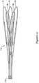
- FIG. 1is a side view of an example medical device system 10. It should be noted that some features of system 10 are either not shown, or are shown schematically, in Figure 1 for simplicity. Additional details regarding some of the components of system 10 are provided in other figures in greater detail.
- System 10may be used to deliver and/or deploy a variety of medical devices to a number of locations within the anatomy.
- system 10is a replacement heart valve delivery system (e.g., a replacement aortic valve delivery system) that can be used for percutaneous delivery of a replacement heart valve. This, however, is not intended to be limiting as system 10 may also be used for other interventions including mitral valve replacement, valve repair, valvuloplasty, and the like, or other similar interventions.
- System 10may generally be described as a catheter system that includes an outer sheath or catheter 12 and an inner catheter or tube 14 (a portion of which is shown in Figure 1 in phantom line) extending at least partially through outer sheath 12.
- a medical device implant 16may be coupled to inner catheter 14 and disposed within outer sheath 12 during delivery of implant 16.
- a handle 18may be disposed at the proximal end of outer sheath 12 and inner catheter 14. In general, handle 18 may be configured to manipulate the position of outer sheath 12 relative to inner catheter 14 as well as aid in the deployment of implant 16.
- system 10may be advanced percutaneously through the vasculature to a position adjacent to an area of interest.
- system 10may be advanced through the vasculature to a position adjacent to a defective aortic valve.
- implant 16may be generally disposed in an elongated and low profile "delivery" configuration within outer sheath 12. Once positioned, outer sheath 12 may be retracted to expose implant 16.
- Implant 16may be actuated in order to expand implant into a generally shortened and larger profile "deployed" configuration suitable for implantation within the anatomy.
- system 10can be removed from the vasculature, leaving implant 16 in place to function as, for example, a suitable replacement for the native aortic valve.
- implant 16may be deployed within the native valve (e.g., the native valve is left in place and not excised). Alternatively, the native valve may be removed and implant 16 may be deployed in its place as a replacement.
- Figures 2-13illustrate some of the components of system 10.
- Figure 2is a cross-sectional side view of outer sheath 12.
- outer sheath 12has a proximal portion 20 and a distal portion 22.
- Distal portion 22may have a slightly enlarged or flared inner diameter, which may provide additional space for holding implant 16 therein.
- the inner diameter of outer sheath 12 along proximal portion 20may be in the range of about 0.254 to 1.27 cm (0.10 to 0.50 inches), or about 0.508 to 1.016 cm (0.20 to 0.40 inches), or about 0.508 to 0.762 cm (0.20 to 0.30 inches), or about 0.56388 ⁇ 0.0508 cm (0.222 ⁇ 0.002 inches).
- the inner diameter of outer sheath 12 along distal portion 22may be in the range of about 0.254 to 1.27 cm (0.10 to 0.50 inches), or about 0.508 to 1.016 cm (0.20 to 0.40 inches), or about 0.508 to 0.762 cm (0.20 to 0.30 inches), or about 0.579 to 0.5842 cm (0.228 to 0.230 inches).
- distal tip 24At the distal end of distal portion 22 may be a distal tip 24, which may be flared or otherwise have a funnel-like shape.
- the funnel-like shapeincreases the outer diameter (and inner diameter) of outer sheath 12 at distal tip 24 and may aid in the sheathing and/or re-sheathing of implant 16 into outer sheath 12.
- outer sheath 12may have a generally constant outer diameter.
- outer sheath 12may have an outer diameter in the range of about 0.254 to 1.27 cm (0.10 to 0.50 inches), or about 0.508 to 1.016 cm (0.20 to 0.40 inches), or about 0.508 to 0.762 cm (0.20 to 0.30 inches), or about 0.6858 cm (0.270 inches). These are just examples.
- outer sheath 12may also have a length that is appropriate for reaching the intended area of interest within the anatomy.
- outer sheath 12may have a length in the range of about 30 to 200 cm, or about 60 to 150 cm, or about 100 to 120 cm, or about 108 ⁇ 0.20 cm.
- Outer sheath 12may also be curved.
- a distal section of outer sheath 12may be curved.
- the radius of the curve(measured from the center of outer sheath 12) may be in the range of about 2 to 6 cm (20 to 60 mm), or about 3 to 4 cm (30 to 40 mm), or about 3.675 cm (36.75 mm). Again, these dimensions are examples and are not intended to be limiting.
- Outer sheath 12may be formed from a singular monolithic tube or unitary member. Alternatively, outer sheath 12 may include a plurality of layers or portions. One or more of these layers may include a reinforcing structure such as a braid, coil, mesh, combinations thereof, or the like.
- Figure 3illustrates one example of a multilayer structure for outer sheath 12.
- outer sheath 12may include an inner liner or layer 26.
- An intermediate or tier layer 28may be disposed on inner liner 26.
- a reinforcement 30may be disposed on intermediate layer 28.
- a topcoat or outer layer 32may be disposed on reinforcement 30.
- an outer coating 34(e.g., a lubricious coating, a hydrophilic coating, a hydrophobic coating, etc.) may be disposed along portions or all of topcoat 32.
- outer sheath 12including embodiments including two or more layers that may be different from those shown in Figure 3 , embodiments without a reinforcement, and the like, or other suitable configurations.
- inner liner 26may include a polymeric material such as fluorinated ethylene propylene (FEP) and may have a thickness in the range of about 0.00254 to 0.0127 cm (0.001 to 0.005 inches) or about 0.00762 ⁇ 0.00254 (0.003 ⁇ 0.001 inches)
- intermediate layer 28may include a polymer material such as polyether block amide (e.g., PEBAX 6333) and may have a thickness in the range of about 0.00254 to 0.0127 cm (0.001 to 0.005 inches) or about 0.00508 ⁇ 0.00254 (0.002 ⁇ 0.001 inches)
- outer coating 34may include a polymer material such as polyether block amide (e.g., PEBAX 7233) and may have a thickness in the range of about 0.00254 to 0.0254 cm (0.001 to 0.01 inches).
- outer coating 34may vary in thickness. For example, along proximal portion 20 outer coating 34 may have greater thickness, such as about 0.0127 to about 0.0508 cm or about 0.02159 cm (0.005 to 0.02 inches or about 0.0085 inches), than along distal portion 22 and/or distal tip 24, which may be about 0.0127 to about 0.0508 cm or about 0.01651 cm (e.g., about 0.005 to 0.02 inches or about 0.0065 inches). These are just examples as other suitable materials may be used.
- distal tip 24may also vary.
- inner liner 26i.e., a 2.5 mm section thereof
- outer sheath 12e.g., around reinforcement 30 and topcoat 32
- a ring member(not shown) made from a suitable material such as a 55D polyether block amide (e.g., 55D PEBAX) may be disposed over inner liner 26 and heat bonded to form distal tip 24. This may form the funnel-like shape of distal tip 24.
- Reinforcement 30may also vary in form.
- reinforcement 30may take the form of a braid, coil, mesh, or the like.
- reinforcement 30may include a metallic braid (e.g., stainless steel).
- reinforcement 30may also include additional structures such as one or more longitudinally-extending strands.
- reinforcement 30may include a pair of longitudinally-extending aramid and/or para aramid strands (for example, KEVLAR®) disposed on opposite sides of the braid. These strands may or may not be woven into portions or all of the braid.
- FIG. 4is a side view of the inner catheter 14.
- a distal end region of inner catheter 14may include a step in outer diameter 40 that defines a decreased outer diameter section 42.
- decreased outer diameter section 42may have an outer diameter in the range of about 0.127 to 0.635 cm (0.05 to 0.25 inches), or about 0.254 to 0.508 cm (0.10 to 0.20 inches), or about 0.38608 ⁇ 0.00762 (0.152 ⁇ 0.003 inches) as opposed to the remainder of inner catheter 14 where the outer diameter may be in the range of about 0.127 to 0.762 cm (0.05 to 0.30 inches), or about 0.254 to 0.635 cm (0.10 to 0.25 inches), or about 0.508 ⁇ 0.0254 cm (0.20 ⁇ 0.01 inches).
- Decreased outer diameter section 42may define a region where other components of system 10 may be attached. Some additional details regarding these components can be found herein.
- inner catheter 14may take the form of an extruded polymer tube. Other forms are also contemplated including other polymer tubes, metallic tubes, reinforced tubes, or the like including other suitable materials such as those disclosed herein.
- inner catheter 14is a singular monolithic or unitary member. In other embodiments, inner catheter 14 may include a plurality of portions or segments that are coupled together. The total length of inner catheter may be in the range of about 60 to 150 cm, or about 80 to 120 cm, or about 100 to 115 cm, or about 112 ⁇ 0.02 cm.
- inner catheter 14may also be curved, for example adjacent to the distal end thereof.
- inner catheter 14may have one or more sections with a differing hardness/stiffness (e.g., differing shore durometer).
- inner cathetermay have a proximal region 44a and an intermediate region 44b.
- Proximal region 44amay include a generally stiff polymeric material such as a 72D polyether block amide (e.g., 72D PEBAX) and may have a length in the range of about 60 to 150 cm, or about 80 to 120 cm, or about 100 to 115 cm, or about 109.5 ⁇ 0.02 cm.
- Intermediate region 44bmay include a 40D polyether block amide (e.g., 40D PEBAX) and may have a length in the range of about 5 to 25 mm, or about 10 to 20 mm, or about 15 ⁇ 0.01 mm.
- Decreased outer diameter section 42may also differ from regions 44a/44b and, in some embodiments, may include a 72D polyether block amide (e.g., 72D PEBAX) and may have a length in the range of about 0.5 to 2 cm (5 to 20 mm), or about 0.8 to 1.5 cm (8 to 15 mm), or about 1 ⁇ 0.001 cm (10 ⁇ 0.01 mm). These are just examples.
- Inner catheter 14may include one or more lumens.
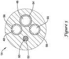
- Figure 5which is a cross-sectional view of inner catheter 14 adjacent to proximal end portion 36
- inner catheter 14may include a first lumen 46, a second lumen 48, a third lumen 50, and a fourth lumen 52.
- lumens 46/48/50/52extend along the entire length of inner catheter 14.
- Other embodimentsare contemplated, however, where one or more of lumens 46/48/50/52 extend along only a portion of the length of inner catheter 14.
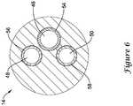
- fourth lumen 52may stop just short of the distal end of inner catheter 14 and/or be filled in at its distal end to effectively end fourth lumen 52 proximal of the distal end of inner catheter 14, as illustrated in Figure 6 by the absence of fourth lumen 52 adjacent to the distal end of inner catheter 14.
- first lumen 46Disposed within first lumen 46 may be push-pull rods 84 (not shown in Figure 5 , seen in other figures including Figure 7 ), which are used to expand and/or elongate implant 16 as explained in more detail herein.
- first lumen 46may be lined with a low friction liner 54 (e.g., a FEP liner).
- second lumen 48Disposed within second lumen 48 may be a pin release mandrel 92 (not shown in Figure 5 , seen in other figures including Figure 7 ), which is also explained in more detail herein.
- second lumen 48may be lined with a hypotube liner 56.
- Third lumen 50may be a guidewire lumen and this lumen may also be lined with a hypotube liner 58.
- Fourth lumen 52may be used to house a non-stretch wire 60.
- the form of non-stretch wire 60may vary.
- non-stretch wire 60may take the form of a stainless steel braid.
- the non-stretch wire 60may optionally include a pair of longitudinally-extending aramid and/or para aramid strands (for example, KEVLAR®) disposed on opposite sides of the braid.
- non-stretch wire 60may be embedded within fourth lumen 52.
- non-stretch wire 60may extend to a position adjacent to distal end portion 38 but not fully to the distal end of inner catheter 14 as illustrated in Figure 6 by the absence of fourth lumen 52 adjacent to the distal end of inner catheter 14.
- a short distal segment of fourth lumen 52may be filled in with polymer material adjacent to the distal end of inner catheter 14.
- Inner catheter 14may also include a guidewire extension tube 62 that extends distally from distal end portion 38.
- a nose cone 64is attached to guidewire extension tube 62.
- Nose cone 64generally is designed to have an atraumatic shape.
- Nose cone 64may also include a ridge or ledge 66 that is configured to abut the distal tip 24 of outer sheath 12 during delivery of implant 16.
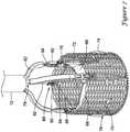
- FIG. 7illustrates some of the additional components of system 10 and implant 16.
- implant 16includes a plurality of valve leaflets 68 (e.g., bovine pericardial) which are secured to a cylindrical braid 70 at a post or commissure post 72, for example at the commissure portions of the leaflets 68.
- implant 16includes three leaflets 68 secured to braid 70 with three posts 72.
- Leaflets 68may also be secured to the base or "distal end" of braid 70.
- the posts 72in turn, may be secured to braid 70 (e.g., along the interior of braid 70) with sutures or other suitable mechanisms.
- buckles 76Positioned adjacent to (e.g., longitudinally spaced from and aligned with) posts 72 are a plurality of buckles 76, which may also be sutured to braid 70 (e.g., along the interior of braid 70).
- one buckle 76is attached to braid 70 adjacent to each of the three posts 72.
- braid 70has a total of three buckles 76 and three posts 72 attached thereto.
- a seal 74(shown in cross-section) may be disposed about braid 70 and, as the name suggests, may help to seal implant 16 within a target implant site or area of interest.
- Coupler 78may generally include a cylindrical base (not shown) that is attached to inner catheter 14 (e.g., disposed about and attached to reduced outer diameter section 42). Projecting distally from the base are three fingers that are each configured to engage with implant 16 at posts 72 and buckles 76. A collar 80 may further assist in holding together these structures.
- a guide 82may be disposed over each of the fingers and may serve to keep the fingers of coupler 78 associated with push-pull rods 84 extending adjacent to coupler 78.
- a pin release assembly 86may be a linking structure that keeps posts 72, buckles 76, and push-pull rods 84 associated with one another.
- Pin release assembly 86includes a plurality of individual pins 88 that may be joined together via a coiled connection 90 and held to a pin release mandrel 92 with a ferrule 94.
- implant 16is secured at the distal end of inner catheter 14 by virtue of the association of the fingers of coupler 78 being coupled with a projecting proximal end of buckles 76 (and being held in place with collar 80 disposed over the connection) and by virtue of pins 88 securing together push-pull rods 84 and posts 72.
- outer sheath 12may be withdrawn (e.g., moved proximally relative to inner catheter 14) to expose implant 16.
- push-pull rods 84can be used to expand and "lock" implant 16 in the expanded or deployed configuration by proximally retracting push-pull rods 84 to pull posts 72 into engagement with buckles 76.
- pins 88can be removed, thereby uncoupling push-pull rods 84 from posts 72, which allows implant 16 to be released from system 10 and deployed in the anatomy.
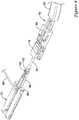
- FIGs 8-11illustrate the locking system utilized with system 10.
- push-pull rod 84extends through guide 82 adjacent to the fingers of coupler 78, through collar 80, through buckle 76, and into a hollow t-shaped bar portion 96 of post 72.
- the distal end of push-pull rod 84may include an opening or aperture (not shown) that can be aligned with an opening 98 of t-shaped bar portion 96.
- pin 88When so aligned, pin 88 can be looped through opening 98 and the opening of push-pull rod 84. This secures push-pull rod 84 to post 72 and forms a configuration of these structures that can be utilized during delivery of implant 16.
- the proximal end of post 72 and the distal end of buckle 76are longitudinally separated and, accordingly, implant 16 is in an elongated and generally low-profile configuration suitable for delivery.
- a cliniciancan proximally retract push-pull rod 84, thereby moving the proximal ends of posts 72 toward the distal ends of buckles 76 in order to expand implant 16.
- push-pull rod 84can be retracted sufficiently far enough to lock post 72 with buckle 76 so as to lock implant in an expanded configuration suitable for implantation within the anatomy.
- Figure 9illustrates push-pull rod 84 proximally retracted. In doing so, post 72 is brought into contact with buckle 76. More particularly, a raised, generally transversely-oriented ridge 100 on t-shaped bar portion 96 may be pulled proximally past buckle 76 so that post 72 is secured and held in place by buckle 76.
- push-pull rods 84distally to "unlock" implant 16, thereby allowing for repositioning and/or retraction.
- pins 88may be pulled (e.g., removed from openings 98 and the openings in push-pull rods 84) to uncouple push-pull rods 84 from posts 72 as shown in Figure 10 . Further retraction of push-pull rods 84 causes a longitudinally-oriented ridge 102 on push-pull rods 84 to engage collar 80 and causes collar 80 to slide proximally along the fingers of coupler 78.
- a forked end 104 of the fingerswhich has a groove 106 formed therein, is exposed and can be uncoupled from a rail 108, which has a projection 110 formed thereon that is configured to mate with groove 106, as shown in Figure 11 .
- system 10can be removed from the anatomy, leaving behind the expanded and deployed implant 16.
- Figures 12-13illustrate another component that may be included with system 10.
- Figure 12is a side view of a portion of a sheathing aid 112.
- sheathing aid 112includes a base 114 and a group of petals including a set of three longer petals 116 and a pair of shorter petals 118.
- a group of petals 116/118may be positioned between each of the fingers of coupler 78.
- the coupler 78may have a total of three fingers
- sheathing aid 112may have a total of fifteen petals (e.g., three groups that each include three "long" petals 116 and two "short” petals 118, with each group being positioned between adjacent pairs of fingers of coupler 78).
- Base 114may be secured to inner catheter 14 adjacent to coupler 78 (e.g., underneath coupler 78 and between coupler 78 and inner catheter 14).
- Sheathing aid 112may be used to aid in the sheathing of implant 16 into outer sheath 12.
- sheathing aid 112may aid in the initial sheathing of implant 16 (e.g., removing implant 16 from a packaging container such as a bottle and pulling implant 16 into outer sheath 12) and in re-sheathing implant 16 during repositioning and/or retraction of implant 16 within the area of interest.
- Sheathingmay be accomplished via the arrangement and positioning of the various petals 116/118.
- Figure 13illustrates the longer petals 116 woven in and out of braid 70, and the shorter petals 118 disposed along the exterior of braid 70 acting as a funnel for sheathing.
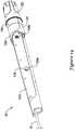
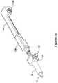
- Figure 14is a side view of handle 18.
- handle 18includes a handle housing 120.
- a rotatable control knob 122may be disposed about handle housing 120 (e.g., at a proximal end of handle housing 120) and may be used to move one or more of the components of system 10 (e.g., outer sheath 12, push-pull rods 84, etc.).
- a rotatable collar 156may be disposed about the handle housing 120.
- control knob 122may be disposed about a proximal portion of collar 156.
- a slidable door 124may also be disposed about handle housing 120.
- Door 124may translate distally to expose a distal portion of rotatable collar 156 (not shown in Figure 14 , can be seen in other figures including Figures 19-20 ) positioned generally under door 124.
- Collar 156may be rotated to move one or more components of system 10 (e.g., push-pull rods 84, pin release mandrel 92, etc.).
- Handle 18may also include one or more apertures 129a/129b and/or flush ports 126/128 that can be used to flush system 10.
- distal flush port 126 and proximal flush port 128are disposed within the handle housing 120 and may generally face laterally relative to a longitudinal axis of the handle housing 120 so as to be accessible from the exterior of the handle housing 120 through distal aperture 129a and proximal aperture 129b, respectively.
- Some components of system 10 related to the flush ports 126/128may be seen in greater detail in Figures 23-25 .
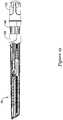
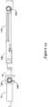
- Figure 15is a side view of handle 18 with a portion of handle housing 120 removed, exposing at least some of the interior components. It should be noted that some components within handle 18 are not shown in Figures 15-20 for clarity.
- handle housing 120includes a side wall defining an interior space of the handle housing 120. In some embodiments, the side wall substantially surrounds the interior space.
- outer sheath 12 and inner catheter 14may extend through a distal end of the handle housing 120.
- the proximal flush port 128 and the distal flush port 126may be disposed within the interior space.
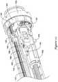
- Outer sheath 12may be attached (e.g., fixedly attached) to an axially movable sheath adapter 130, as seen in Figures 15 and 23-25 .
- Sheath adapter 130is attached to a sheath carriage 132, which may be threaded onto a lead screw 134. Sheath carriage 132 may move axially within the handle housing 120 in response to rotation of the control knob 122.
- Distal flush port 126may be disposed on sheath adapter 130. As such, distal flush port 126 may be axially and/or longitudinally movable within the interior space of the handle housing 120 when the control knob 122 is rotated.
- distal flush port 126is in fluid communication with the interior or lumen of outer sheath 12, so as to provide access to the interior or lumen of outer sheath 12 (e.g., access to space between inner catheter 14 and outer sheath 12) so that a clinician can flush fluid through the lumen of outer sheath 12 to remove any unwanted materials (e.g., air, fluid, contaminants, etc.) therein prior to use of system 10.
- any unwanted materialse.g., air, fluid, contaminants, etc.
- distal flush port 126has a luer type connector (e.g., a one-way luer connector) that allows a flushing device such as a syringe with a corresponding connector to be attached thereto for flushing.
- the flushing devicee.g., a syringe
- the flushing devicecan be directly connected to the distal flush port 126 through distal aperture 129a. That is, a flushing device may be connected to the distal flush port 126 without the aid or presence of other intervening elements or structure such as tubing or adapters, and the like.
- a direct connectionmay reduce opportunity for leaks or interference of connecting elements with other components within handle 18 during operation, as well as streamline overall assembly of the medical device system 10.
- Inner catheter 14may extend through and proximally from sheath adapter 130.
- a proximal end of inner catheter 14is attached (e.g., fixedly attached) to an interior body or diverter 136.
- a proximal end of diverter 136is attached (e.g., fixedly attached) to a distal end of a support body 140.
- the diverter 136 and support body 140are fixed in position relative to the handle housing 120. Accordingly, inner catheter 14 may be fixed in position relative to the handle housing 120.
- diverter 136 and/or support body 140may have one or more passageways or lumens formed therein.
- push-pull rods 84 and/or pin release mandrel 92may extend through respective passageways.
- the proximal ends of push-pull rods 84 and/or pin release mandrel 92may each be attached to a shaft or hypotube (e.g., solid in cross-section, tubular, etc.), and each of the shafts may extend through the one or more passageways.
- first shaft or hypotube 142 and a second shaft or hypotube 144may extend through the passageways in diverter 136 and/or support body 140, and in some embodiments, the first shaft or hypotube 142 extends through a first passageway and the second shaft or hypotube 144 extends through a second passageway that is separate or distinct from the first passageway.
- first shaft 142is attached (e.g., fixedly attached) to pin release mandrel 92.
- second shaft 144is attached (e.g., fixedly attached) to push-pull rods 84. It should be noted that at in least some embodiments of system 10, three push-pull rods 84 are utilized.
- the three push-pull rods 84come together (e.g., brought into contact with one another or otherwise brought into relatively close proximity with one another) adjacent to the distal end of inner catheter 14 and enter first lumen 46.
- push-pull rods 84may be attached to one another.
- push-pull rods 84may be welded together about 10.16 cm (about 4.00 inches) from their distal ends.
- push-pull rods 84may be welded together proximate their proximal ends in addition to or instead of the distal weld. Proximally thereafter, push-pull rods 84 may extend to second shaft 144.
- a hypotube(e.g., hypotube liner 58 disposed along guidewire lumen 52) may extend through diverter 136 within a passageway therein and then be "diverted” around a portion of diverter 136 and support body 140, and ultimately be extended to a position at the proximal end of handle 18 so as to provide a user access to guidewire lumen 52.
- Support body 140has a plurality of lumens 141 (e.g. two, or more, lumens) extending longitudinally therethrough, as shown in Figure 25 .
- Proximal flush port 128is disposed on or attached (e.g., fixedly attached) to the support body 140, and is in fluid communication with the inner catheter 14.
- the proximal flush port 128is in fluid communication with the lumens 141 of support body 140.
- the lumens 141 of support body 140are fluidly connected to diverter 136 and/or inner catheter 14.
- Proximal flush port 128may be used to flush the lumens 141 of inner catheter 14 and, for example, may function similarly to distal flush port 126 described above.
- fluid introduced into the proximal flush port 128may pass through the inner catheter 14 and discharge from a distal end thereof.
- Fluid introduced into the distal flush port 126may similarly pass through the lumen of outer sheath 12 (e.g., within the space between the inner catheter 14 and the outer sheath 12) and discharge from a distal end thereof.
- fluid introduced into one of the outer sheath 12 and the inner catheter 14does not enter an interior or lumen of the other (e.g., fluid introduced into the inner catheter 14 does not enter the lumen of outer sheath 12) upon discharge from the respective distal end.
- Proximal flush port 128may be attached to support body 140, and distal flush port may be attached to sheath adapter 130 using one or more of a number of various fastening or attachment means.
- flush ports 126/128may be held within the sheath adapter 130 and/or support body 140 by pins extending across a flange formed on the flush ports 126/128.
- flush ports 126/128may be threaded and screwed into place within the sheath adapter 130 and/or support body 140.
- flush ports 126/128may be attached to sheath adapter 130 and/or support body 140 via a snap-fit, press-fit, or interference fit.
- an adhesivemay be added to seal the connections against leaks.
- an O-ring or other compression sealmay be utilized between adjoining components.
- first shaft 142may be secured to a slider 146 and second shaft 144 may be secured to a force limiter body 150.
- the connections between the various componentsmay include a number of different types of connections including mechanical bonding (e.g., pinning, threading, interference fit, etc.), adhesive bonding, thermal bonding, etc.
- Slider 146may be slidable relative to force limiter body 150. In some embodiments, slider 146 may be selectively locked to force limiter body 150, thereby preventing relative movement between the slider 146 and the force limiter body 150.
- Force limiter body 150may be secured to a push-pull rod carriage 152, which may be threaded onto lead screw 134. Thus, movement of lead screw 134 can cause movement of push-pull rod carriage 152 and force limiter body 150 and thus, push-pull rods 84 (via second shaft 144).
- force limiter body 150forms or defines a stop point that provides tactile feedback (e.g., resistance to further rotation of control knob 122) to the user indicating that push-pull rods 84 have been retracted proximally a sufficient distance to lock posts 72 with buckles 76.
- tactile feedbacke.g., resistance to further rotation of control knob 122
- a chock 148may be positioned adjacent to slider 146 to selectively lock slider 146 to force limiter body 150. In order to allow pin release mandrel 92 to be proximally retracted to pull pins 88, chock 148 can be rotated or otherwise moved to a secondary position or configuration.
- chock 148no longer forms a barrier to further movement of, for example, slider 146 and pin release mandrel 92. Accordingly, with chock 148 no longer acting as an impediment, slider 146 and pin release mandrel 92 can be proximally retracted to facilitate deployment of implant 16 by allowing pins 88 to be pulled.
- Handle 18also includes a rotatable ring 155 with internal teeth that are configured to engage with teeth on a gear 157 coupled to lead screw 134.
- Ring 155is coupled to control knob 122 so that rotation of control knob 122 results in analogous motion of ring 155 and thus lead screw 134.
- Handle 18is generally configured for coordinated movement of multiple structures of system 10.
- handle 18is configured to allow a user to move outer sheath 12 (e.g., relative to inner catheter 14), move push-pull rods 84, and move pin release mandrel 92.
- handle 18is configured so that the appropriate structure can be moved at the appropriate time during the intervention so that implant 16 can be delivered in an efficient manner.
- Some examples of how the coordinated movement of system 10 may occur within handle 18may be similar to those disclosed in U.S. Patent Application Pub. No. US 2010/0280495 .
- handle 18may include a lost motion barrel 158.
- Lost motion barrel 158is configured to engage carriages 132/152 and/or screws associated with carriages 132/152 at different times during the intervention to stop motion (e.g., create "lost motion" of the appropriate carriage).
- Figures 16-19illustrate some of the coordinated motion achieved by handle 18. It should be noted that some elements of system 10 are not shown in Figures 16-20 for clarity.
- Figure 16illustrates a first position or state for handle 18 where outer sheath 12 is extended distally relative to inner catheter 14 (and handle 18) so as to fully sheath (e.g., contain) implant 16. While in this position, sheath carriage 132 is positioned adjacent to the distal end of handle 18.
- a rod screw 152a associated with push-pull rod carriage 152is extended distally from push-pull rod carriage 152 and positioned within lost motion barrel 158.
- lead screw 134Upon rotation of control knob 122 (e.g., in the clockwise direction), lead screw 134 begins to rotate. Rotation of lead screw 134 causes sheath carriage 132 to move along lead screw 134 in the proximal direction, resulting in proximal movement of outer sheath 12 (e.g., "unsheathing" implant 16). This initial rotation of lead screw 134 also causes rod screw 152a to rotate.
- rod screw 152amay be engaged with a helical thread disposed along the interior of lost motion barrel 158.
- rod screw 152ais spaced from push-pull rod carriage 152, it does not exert a force onto push-pull rod carriage 152.
- initial motion of control knob 122does not result in movement of push-pull rod carriage 152 and, instead, only results in translation of sheath carriage 132 and rotation (and translation) of rod screw 152a.
- rod screw 152a(e.g., the knob formed therein) reaches an essentially linear thread or pathway formed at the end of lost motion barrel 158.
- the linear threadallows rod screw 152a to translate along lead screw 134 to a position where rod screw 152a contacts (e.g., is threaded within and abuts) push-pull rod carriage 152. In doing so, rod screw 152a can contact and move proximally push-pull carriage 152. Accordingly, further rotation of lead screw 134 not only causes sheath carriage 132 to move proximally but also causes push-pull rod carriage 152 to move proximally as shown in Figure 17 .
- a sheath carriage screw 132a of sheath carriage 132enters lost motion barrel 158 as shown in Figure 18 .
- Thismay occur in a manner similar to how rod screw 152a threads and unthreads with the helical thread formed along lost motion barrel 158.
- sheath carriage screw 132amay follow an essentially linear thread or pathway formed along or adjacent to lost motion barrel 158.
- sheath carriage screw 132ae.g., a knob or projection formed thereon
- sheath carriage screw 132amay shift into engagement with the helical thread within lost motion barrel 158 and rotate.
- This rotation"unthreads" sheath carriage screw 132a from sheath carriage 132. Accordingly, additional rotation of lead screw 134 results in continued proximal movement of push-pull rod carriage 152 while motion of sheath carriage 132 ceases.
- lead screw 134has a plurality of portions, for example a first portion 134a and a second portion 134b, with a differing pitch to its thread. This may allow carriages 132/152 to travel at different rates along lead screw 134.
- the pitch of lead screw 134 along which sheath carriage 132 translatesmay be generally more spaced or slanted than at positions adjacent to push-pull rod carriage 152.
- the coordinated movement of carriages 132/152also may be configured so that sheath carriage 132 translates along lead screw 134 at a greater rate than push-pull rod carriage 152.
- Other configurationsare contemplated where the above-mentioned configuration is reversed as well as further configurations where the pitch of lead screw 134 is essentially constant or includes a number of different pitch regions.
- door 124may be slid distally along a collar 156 (which is positioned on handle 18) as shown in Figure 19 .
- Push-pull rod carriage 152may also include a radially-extending proximal flag member 164.
- flag member 164may be designed as a feature that can prevent collar 156 from being rotated earlier than desired (and, thus, prevent pins 88 from being pulled earlier than desired).
- flag member 164may be positioned within and follow a groove (not shown) along the interior of collar 156.
- flag member 164While positioned within the groove, flag member 164 essentially forms a physical barrier that prevents collar 156 from rotating relative to handle housing 120.
- push-pull rod carriage 152is translated proximally to the back of handle housing 120 (e.g., when push-pull rods 84 are proximally retracted so as to lock posts 72 with buckles 76)
- flag member 164exits the groove in collar 156. Accordingly, flag member 164 no longer impedes rotation of collar 156 and, as such, collar 156 can now be rotated to pull pins 88.
- Collar 156via ring 154, is associated with a gear 160 engaged with a secondary screw 162. Notches at a proximal end of collar 156 engage protrusions on ring 154 such that rotation of collar 156 causes corresponding rotation of ring 154 and thus secondary screw 162.
- chock 148The initial rotation of collar 156 is sufficient to rotate chock 148 (e.g., via a mechanical interaction between collar 156 and chock 148 that causes chock 148 to shift) from a first configuration where slider 146 (and, thus, pin release mandrel 92) is selectively locked to force limiter body 150, to a secondary configuration, which permits slider 146 to translate along secondary screw 162 as secondary screw 162 rotates, to proximally retract and pull pins 88 (e.g., via pin release mandrel 92).
- chock 148 in the first configurationengages a ridge 168 along a top portion of force limiter body 150 which forms a physical barrier that prevents proximal translation of slider 146 relative to force limiter body 150.
- slider 146can translate proximally within a groove 166 disposed in the top portion of force limiter body 150 (e.g., as seen in Figure 22 ), as collar 156 is rotated about the handle housing 120 to pull the pins 88 from the openings 98 and the openings in the distal ends of the push-pull rods 84. Once pins 88 have been removed, push-pull rods 84 may be withdrawn from implant 16, thereby deploying the implant at the target site (area of interest).
- control knob 122may be rotated to move the sheath carriage 132 distally within the handle housing 120, thereby moving outer sheath 12 distally relative to inner catheter 14 and three-finger coupler 78 so as to cover or re-sheath the elements of system 10 disposed at the distal end. System 10 may then be removed from the patient's anatomy.
- the materials that can be used for the various components of system 10 (and/or other systems disclosed herein) and the various tubular members disclosed hereinmay include those commonly associated with medical devices.
- outer sheath 12 and/or inner catheter 14are commonly associated with medical devices.
- thisis not intended to limit the devices and methods described herein, as the discussion may be applied to other similar tubular members and/or components of tubular members or devices disclosed herein.
- Outer sheath 12 and/or inner catheter 14may be made from a metal, metal alloy, polymer (some examples of which are disclosed below), a metal-polymer composite, ceramics, combinations thereof, and the like, or other suitable material.
- suitable metals and metal alloysinclude stainless steel, such as 304V, 304L, and 316LV stainless steel; mild steel; nickel-titanium alloy such as linear-elastic and/or super-elastic nitinol; other nickel alloys such as nickel-chromium-molybdenum alloys (e.g., UNS: N06625 such as INCONEL® 625, UNS: N06022 such as HASTELLOY® C-22®, UNS: N10276 such as HASTELLOY® C276®, other HASTELLOY® alloys, and the like), nickel-copper alloys (e.g., UNS: N04400 such as MONEL® 400, NICKELVAC® 400, NICORROS® 400
- Linear elastic and/or non-super-elastic nitinolmay be distinguished from super elastic nitinol in that the linear elastic and/or non-super-elastic nitinol does not display a substantial "superelastic plateau” or “flag region” in its stress/strain curve like super elastic nitinol does.
- linear elastic and/or non-super-elastic nitinolas recoverable strain increases, the stress continues to increase in a substantially linear, or a somewhat, but not necessarily entirely linear relationship until plastic deformation begins or at least in a relationship that is more linear that the super elastic plateau and/or flag region that may be seen with super elastic nitinol.
- linear elastic and/or non-super-elastic nitinolmay also be termed "substantially" linear elastic and/or non-super-elastic nitinol.
- linear elastic and/or non-super-elastic nitinolmay also be distinguishable from super elastic nitinol in that linear elastic and/or non-super-elastic nitinol may accept up to about 2-5% strain while remaining substantially elastic (e.g., before plastically deforming) whereas super elastic nitinol may accept up to about 8% strain before plastically deforming. Both of these materials can be distinguished from other linear elastic materials such as stainless steel (that can also can be distinguished based on its composition), which may accept only about 0.2 to 0.44 percent strain before plastically deforming.
- the linear elastic and/or non-super-elastic nickel-titanium alloyis an alloy that does not show any martensite/austenite phase changes that are detectable by differential scanning calorimetry (DSC) and dynamic metal thermal analysis (DMTA) analysis over a large temperature range.
- DSCdifferential scanning calorimetry
- DMTAdynamic metal thermal analysis
- the mechanical bending properties of such materialmay therefore be generally inert to the effect of temperature over this very broad range of temperature.
- the mechanical bending properties of the linear elastic and/or non-super-elastic nickel-titanium alloy at ambient or room temperatureare substantially the same as the mechanical properties at body temperature, for example, in that they do not display a super-elastic plateau and/or flag region.
- the linear elastic and/or non-super-elastic nickel-titanium alloymaintains its linear elastic and/or non-super-elastic characteristics and/or properties.
- the linear elastic and/or non-super-elastic nickel-titanium alloymay be in the range of about 50 to about 60 weight percent nickel, with the remainder being essentially titanium. In some embodiments, the composition is in the range of about 54 to about 57 weight percent nickel.
- a suitable nickel-titanium alloyis FHP-NT alloy commercially available from Furukawa Techno Material Co. of Kanagawa, Japan. Some examples of nickel titanium alloys are disclosed in U.S. Patent Nos. 5,238,004 and 6,508,803 . Other suitable materials may include ULTANIUMTM (available from Neo-Metrics) and GUM METALTM (available from Toyota).
- a superelastic alloyfor example a superelastic nitinol can be used to achieve desired properties.
- portions or all of outer sheath 12 and inner catheter 14may also be doped with, made of, or otherwise include a radiopaque material.
- Radiopaque materialsare understood to be materials capable of producing a relatively bright image on a fluoroscopy screen or another imaging technique during a medical procedure. This relatively bright image aids the user of system 10 in determining its location.
- Some examples of radiopaque materialscan include, but are not limited to, gold, platinum, palladium, tantalum, tungsten alloy, polymer material loaded with a radiopaque filler, and the like. Additionally, other radiopaque marker bands and/or coils may also be incorporated into the design of system 10 to achieve the same result.
- outer sheath 12 and inner catheter 14, or portions thereofmay be made of a material that does not substantially distort the image and create substantial artifacts (i.e., gaps in the image). Certain ferromagnetic materials, for example, may not be suitable because they may create artifacts in an MRI image. Outer sheath 12 and inner catheter 14, or portions thereof, may also be made from a material that the MRI machine can image.
- MRIMagnetic Resonance Imaging
- Some materials that exhibit these characteristicsinclude, for example, tungsten, cobalt-chromium-molybdenum alloys (e.g., UNS: R30003 such as ELGILOY®, PHYNOX®, and the like), nickel-cobalt-chromium-molybdenum alloys (e.g., UNS: R30035 such as MP35-N® and the like), nitinol, and the like, and others.
- cobalt-chromium-molybdenum alloyse.g., UNS: R30003 such as ELGILOY®, PHYNOX®, and the like
- nickel-cobalt-chromium-molybdenum alloyse.g., UNS: R30035 such as MP35-N® and the like
- nitinoland the like, and others.
- a sheath or coveringmay be disposed over portions or all of outer sheath 12 and inner catheter 14 that may define a generally smooth outer surface for system 10. In other embodiments, however, such a sheath or covering may be absent from a portion of all of system 10, such that outer sheath 12 and inner catheter 14 may form an outer surface.
- the sheathmay be made from a polymer or other suitable material.
- suitable polymersmay include polytetrafluoroethylene (PTFE), ethylene tetrafluoroethylene (ETFE), fluorinated ethylene propylene (FEP), polyoxymethylene (POM, for example, DELRIN® available from DuPont), polyether block ester, polyurethane (for example, Polyurethane 85A), polypropylene (PP), polyvinylchloride (PVC), polyether-ester (for example, ARNITEL® available from DSM Engineering Plastics), ether or ester based copolymers (for example, butylene/poly(alkylene ether) phthalate and/or other polyester elastomers such as HYTREL® available from DuPont), polyamide (for example, DURETHAN® available from Bayer or CRISTAMID® available from Elf Atochem), elastomeric polyamides, block polyamide/ethers, polyether block amide (PEBA, for example available under the trade name PEBAX®), ethylene vinyl acetate
- the exterior surface of the system 10may be sandblasted, beadblasted, sodium bicarbonate-blasted, electropolished, etc.
- a coatingfor example a lubricious, a hydrophilic, a protective, or other type of coating may be applied over portions or all of the sheath, or in embodiments without a sheath over portion of outer sheath 12 and inner catheter 14, or other portions of system 10.
- the sheathmay comprise a lubricious, hydrophilic, protective, or other type of coating.
- Hydrophobic coatingssuch as fluoropolymers provide a dry lubricity which improves device handling and device exchanges.
- Lubricious coatingsimprove steerability and improve lesion crossing capability.
- Suitable lubricious polymersare well known in the art and may include silicone and the like, hydrophilic polymers such as high-density polyethylene (HDPE), polytetrafluoroethylene (PTFE), polyarylene oxides, polyvinylpyrolidones, polyvinylalcohols, hydroxy alkyl cellulosics, algins, saccharides, caprolactones, and the like, and mixtures and combinations thereof.
- HDPEhigh-density polyethylene
- PTFEpolytetrafluoroethylene
- polyarylene oxidespolyvinylpyrolidones
- polyvinylalcoholspolyvinylalcohols
- hydroxy alkyl cellulosicsalgins
- Hydrophilic polymersmay be blended among themselves or with formulated amounts of water insoluble compounds (including some polymers) to yield coatings with suitable lubricity, bonding, and solubility.
- Some other examples of such coatings and materials and methods used to create such coatingscan be found in U.S. Patent Nos. 6,139,510 and 5,772,609 .
- the coating and/or sheathmay be formed, for example, by coating, extrusion, co-extrusion, interrupted layer co-extrusion (ILC), or fusing several segments end-to-end.
- the layermay have a uniform stiffness or a gradual reduction in stiffness from the proximal end to the distal end thereof. The gradual reduction in stiffness may be continuous as by ILC or may be stepped as by fusing together separate extruded tubular segments.
- the outer layermay be impregnated with a radiopaque filler material to facilitate radiographic visualization.
Landscapes
- Health & Medical Sciences (AREA)
- Life Sciences & Earth Sciences (AREA)
- Biomedical Technology (AREA)
- Engineering & Computer Science (AREA)
- Cardiology (AREA)
- Veterinary Medicine (AREA)
- General Health & Medical Sciences (AREA)
- Heart & Thoracic Surgery (AREA)
- Public Health (AREA)
- Animal Behavior & Ethology (AREA)
- Oral & Maxillofacial Surgery (AREA)
- Transplantation (AREA)
- Vascular Medicine (AREA)
- Surgery (AREA)
- Pulmonology (AREA)
- Biophysics (AREA)
- Anesthesiology (AREA)
- Hematology (AREA)
- Nuclear Medicine, Radiotherapy & Molecular Imaging (AREA)
- Medical Informatics (AREA)
- Molecular Biology (AREA)
- Media Introduction/Drainage Providing Device (AREA)
- Prostheses (AREA)
- Surgical Instruments (AREA)
- Endoscopes (AREA)
Description
- Medical devices typically used for cardiovascular system treatments may involve complex and invasive therapies resulting is significant discomfort, pain, and long recovery times for patients. Recently, less invasive, percutaneous treatments have been developed. There is an ongoing need for improved, less invasive cardiovascular treatments.
US 2010/280495 A1 discloses medical devices and delivery systems for delivering medical devices to a target location within a subject.US 2009/182405 A1 discloses systems and methods for deploying implantable devices within the body.US 7 553 322 B2 describes a connector which comprises the male portion of a Luer connector.US 2005/080476 A1 discloses medical device delivery systems.US 2010/049313 A1 discloses a heart valve delivery apparatus for delivery of a prosthetic heart valve to a native valve site via the human vasculature. - The present invention pertains to a medical device as set forth in the claims. The medical device comprises a handle housing having an interior space therein, wherein the handle housing includes a side wall defining the interior space, a proximal aperture extending through the side wall to the interior space, and a distal aperture extending through the side wall to the interior space, an elongate outer sheath having a lumen therein extending distally from the distal end of the handle housing, an elongate inner member extending distally through the distal end of the handle housing within the lumen of the elongate outer sheath, a proximal flush port disposed within the interior space and in fluid communication with the elongate inner member, and a distal flush port disposed within the interior space and in fluid communication with the lumen of the elongate outer sheath, the medical device further comprises a diverter and a support body fixedly attached to a proximal end of the diverter, the diverter and the support body are fixed in position relative to the handle housing, the proximal flush port is attached to the support body, the support body includes two or more lumens extending longitudinally therethrough, the proximal flush port is in fluid communication with the two or more lumens of the support body, the elongated inner member includes several lumens extending longitudinally through the elongated inner member, and at least two of the lumens of the elongated inner member are in fluid communication with the proximal flush port.
- The invention may be more completely understood in consideration of the following detailed description of various embodiments of the invention in connection with the accompanying drawings, in which:
Figure 1 is side view of an example medical device system;Figure 2 is a cross-sectional side view of an example outer sheath;Figure 3 is a transverse cross-sectional view taken through line 3-3 inFigure 2 ;Figure 4 is a side view of an example inner catheter;Figure 5 is a cross-sectional view taken through line 5-5 inFigure 4 ;Figure 6 is a cross-sectional view taken through line 6-6 inFigure 4 ;Figure 7 is a perspective view of a portion of an example implant associated with the example medical device system;Figures 8-11 are perspective views that illustrate an example mechanism for locking an implant;Figure 12 is a side view of a portion of an example sheathing aid;Figure 13 is an enlarged plan view illustrating engagement of the example sheathing aid with an example implant;Figure 14 is a side view of an example handle;Figure 15 is a cut away view illustrating some of the interior components of the example handle;Figures 16-18 illustrate an example of coordinated movement of handle components within the example handle;Figures 19-20 illustrate the rotation of a collar on the example handle;Figures 21-22 illustrate some of the components within the example handle during rotation of the collar; andFigures 23-25 are partial perspective views schematically illustrating some of the components within the example handle.- For the following defined terms, these definitions shall be applied, unless a different definition is given in the claims or elsewhere in this specification.
- All numeric values are herein assumed to be modified by the term "about," whether or not explicitly indicated. The term "about" generally refers to a range of numbers that one of skill in the art would consider equivalent to the recited value (i.e., having the same function or result). In many instances, the term "about" may include numbers that are rounded to the nearest significant figure.
- The recitation of numerical ranges by endpoints includes all numbers within that range (e.g. 1 to 5 includes 1, 1.5, 2, 2.75, 3, 3.80, 4, and 5).
- As used in this specification and the appended claims, the singular forms "a", "an", and "the" include plural referents unless the content clearly dictates otherwise. As used in this specification and the appended claims, the term "or" is generally employed in its sense including "and/or" unless the content clearly dictates otherwise.
- The following detailed description should be read with reference to the drawings in which similar elements in different drawings are numbered the same. The drawings, which are not necessarily to scale, depict illustrative embodiments.
- Diseases and/or medical conditions that impact the cardiovascular system are prevalent in the United States and throughout the world. Traditionally, treatment of the cardiovascular system was often conducted by directly accessing the impacted part of the system. For example, treatment of a blockage in one or more of the coronary arteries was traditionally treated using coronary artery bypass surgery. As can be readily appreciated, such therapies are rather invasive to the patient and require significant recovery times and/or treatments. More recently, less invasive therapies have been developed, for example, where a blocked coronary artery could be accessed and treated via a percutaneous catheter (e.g., angioplasty). Such therapies have gained wide acceptance among patients and clinicians.
- Some relatively common medical conditions may include or be the result of inefficiency, ineffectiveness, or complete failure of one or more of the valves within the heart. For example, failure of the aortic valve can have a serious effect on a human and could lead to serious health condition and/or death if not dealt with. Treatment of defective heart valves poses other challenges in that the treatment often requires the repair or outright replacement of the defective valve. Such therapies may be highly invasive to the patient. Disclosed herein are medical devices that may be used for delivering a medical device to a portion of the cardiovascular system in order to diagnose, treat, and/or repair the system. At least some of the medical devices disclosed herein may be used to deliver and implant a replacement heart valve (e.g., a replacement aortic valve). In addition, the devices disclosed herein may deliver the replacement heart valve percutaneously and, thus, may be much less invasive to the patient. The devices disclosed herein may also provide a number of additional desirable features and benefits as described in more detail below.
Figure 1 is a side view of an examplemedical device system 10. It should be noted that some features ofsystem 10 are either not shown, or are shown schematically, inFigure 1 for simplicity. Additional details regarding some of the components ofsystem 10 are provided in other figures in greater detail.System 10 may be used to deliver and/or deploy a variety of medical devices to a number of locations within the anatomy. In at least some embodiments,system 10 is a replacement heart valve delivery system (e.g., a replacement aortic valve delivery system) that can be used for percutaneous delivery of a replacement heart valve. This, however, is not intended to be limiting assystem 10 may also be used for other interventions including mitral valve replacement, valve repair, valvuloplasty, and the like, or other similar interventions.System 10 may generally be described as a catheter system that includes an outer sheath orcatheter 12 and an inner catheter or tube 14 (a portion of which is shown inFigure 1 in phantom line) extending at least partially throughouter sheath 12. Amedical device implant 16 may be coupled toinner catheter 14 and disposed withinouter sheath 12 during delivery ofimplant 16. Ahandle 18 may be disposed at the proximal end ofouter sheath 12 andinner catheter 14. In general,handle 18 may be configured to manipulate the position ofouter sheath 12 relative toinner catheter 14 as well as aid in the deployment ofimplant 16.- In use,
system 10 may be advanced percutaneously through the vasculature to a position adjacent to an area of interest. For example,system 10 may be advanced through the vasculature to a position adjacent to a defective aortic valve. During delivery,implant 16 may be generally disposed in an elongated and low profile "delivery" configuration withinouter sheath 12. Once positioned,outer sheath 12 may be retracted to exposeimplant 16.Implant 16 may be actuated in order to expand implant into a generally shortened and larger profile "deployed" configuration suitable for implantation within the anatomy. Whenimplant 16 is suitably deployed within the anatomy,system 10 can be removed from the vasculature, leavingimplant 16 in place to function as, for example, a suitable replacement for the native aortic valve. In at least some interventions,implant 16 may be deployed within the native valve (e.g., the native valve is left in place and not excised). Alternatively, the native valve may be removed andimplant 16 may be deployed in its place as a replacement. Figures 2-13 (as well as other figures) illustrate some of the components ofsystem 10. For example,Figure 2 is a cross-sectional side view ofouter sheath 12. Here it can be seen thatouter sheath 12 has aproximal portion 20 and adistal portion 22.Distal portion 22 may have a slightly enlarged or flared inner diameter, which may provide additional space for holdingimplant 16 therein. For example, the inner diameter ofouter sheath 12 alongproximal portion 20 may be in the range of about 0.254 to 1.27 cm (0.10 to 0.50 inches), or about 0.508 to 1.016 cm (0.20 to 0.40 inches), or about 0.508 to 0.762 cm (0.20 to 0.30 inches), or about 0.56388 ± 0.0508 cm (0.222 ± 0.002 inches). The inner diameter ofouter sheath 12 alongdistal portion 22 may be in the range of about 0.254 to 1.27 cm (0.10 to 0.50 inches), or about 0.508 to 1.016 cm (0.20 to 0.40 inches), or about 0.508 to 0.762 cm (0.20 to 0.30 inches), or about 0.579 to 0.5842 cm (0.228 to 0.230 inches). At the distal end ofdistal portion 22 may be adistal tip 24, which may be flared or otherwise have a funnel-like shape. The funnel-like shape increases the outer diameter (and inner diameter) ofouter sheath 12 atdistal tip 24 and may aid in the sheathing and/or re-sheathing ofimplant 16 intoouter sheath 12. Other than atdistal tip 24,outer sheath 12 may have a generally constant outer diameter. For example,outer sheath 12 may have an outer diameter in the range of about 0.254 to 1.27 cm (0.10 to 0.50 inches), or about 0.508 to 1.016 cm (0.20 to 0.40 inches), or about 0.508 to 0.762 cm (0.20 to 0.30 inches), or about 0.6858 cm (0.270 inches). These are just examples. Other embodiments are contemplated that have differing dimensions (including those appropriate for differently sized patients including children) and/or arrangements for the outer diameter and/or inner diameter ofouter sheath 12. These contemplated embodiments include outer sheaths with flared or otherwise variable outer diameters, embodiments with constant inner diameters, combinations thereof, and the like.Outer sheath 12 may also have a length that is appropriate for reaching the intended area of interest within the anatomy. For example,outer sheath 12 may have a length in the range of about 30 to 200 cm, or about 60 to 150 cm, or about 100 to 120 cm, or about 108 ± 0.20 cm.Outer sheath 12 may also be curved. For example, a distal section ofouter sheath 12 may be curved. In one example, the radius of the curve (measured from the center of outer sheath 12) may be in the range of about 2 to 6 cm (20 to 60 mm), or about 3 to 4 cm (30 to 40 mm), or about 3.675 cm (36.75 mm). Again, these dimensions are examples and are not intended to be limiting.Outer sheath 12 may be formed from a singular monolithic tube or unitary member. Alternatively,outer sheath 12 may include a plurality of layers or portions. One or more of these layers may include a reinforcing structure such as a braid, coil, mesh, combinations thereof, or the like.Figure 3 illustrates one example of a multilayer structure forouter sheath 12. For example,outer sheath 12 may include an inner liner orlayer 26. An intermediate ortier layer 28 may be disposed oninner liner 26. Areinforcement 30 may be disposed onintermediate layer 28. A topcoat orouter layer 32 may be disposed onreinforcement 30. Finally, an outer coating 34 (e.g., a lubricious coating, a hydrophilic coating, a hydrophobic coating, etc.) may be disposed along portions or all oftopcoat 32. These are just examples. Several alternative structural configurations are contemplated forouter sheath 12 including embodiments including two or more layers that may be different from those shown inFigure 3 , embodiments without a reinforcement, and the like, or other suitable configurations.- The dimensions and materials utilized for the various layers of
outer sheath 12 may also vary. For example,inner liner 26 may include a polymeric material such as fluorinated ethylene propylene (FEP) and may have a thickness in the range of about 0.00254 to 0.0127 cm (0.001 to 0.005 inches) or about 0.00762 ± 0.00254 (0.003 ± 0.001 inches),intermediate layer 28 may include a polymer material such as polyether block amide (e.g., PEBAX 6333) and may have a thickness in the range of about 0.00254 to 0.0127 cm (0.001 to 0.005 inches) or about 0.00508 ± 0.00254 (0.002 ± 0.001 inches),outer coating 34 may include a polymer material such as polyether block amide (e.g., PEBAX 7233) and may have a thickness in the range of about 0.00254 to 0.0254 cm (0.001 to 0.01 inches). In some embodiments,outer coating 34 may vary in thickness. For example, alongproximal portion 20outer coating 34 may have greater thickness, such as about 0.0127 to about 0.0508 cm or about 0.02159 cm (0.005 to 0.02 inches or about 0.0085 inches), than alongdistal portion 22 and/ordistal tip 24, which may be about 0.0127 to about 0.0508 cm or about 0.01651 cm (e.g., about 0.005 to 0.02 inches or about 0.0065 inches). These are just examples as other suitable materials may be used. - The form of
distal tip 24 may also vary. For example, in at least some embodiments, inner liner 26 (i.e., a 2.5 mm section thereof) may be extended up and around the distal end of outer sheath 12 (e.g., aroundreinforcement 30 and topcoat 32). A ring member (not shown) made from a suitable material such as a 55D polyether block amide (e.g., 55D PEBAX) may be disposed overinner liner 26 and heat bonded to formdistal tip 24. This may form the funnel-like shape ofdistal tip 24. Reinforcement 30 may also vary in form. In at least some embodiments,reinforcement 30 may take the form of a braid, coil, mesh, or the like. For example, in some embodiments,reinforcement 30 may include a metallic braid (e.g., stainless steel). In some of these embodiments,reinforcement 30 may also include additional structures such as one or more longitudinally-extending strands. For example,reinforcement 30 may include a pair of longitudinally-extending aramid and/or para aramid strands (for example, KEVLAR®) disposed on opposite sides of the braid. These strands may or may not be woven into portions or all of the braid.Figure 4 is a side view of theinner catheter 14. A distal end region ofinner catheter 14 may include a step inouter diameter 40 that defines a decreasedouter diameter section 42. For example, decreasedouter diameter section 42 may have an outer diameter in the range of about 0.127 to 0.635 cm (0.05 to 0.25 inches), or about 0.254 to 0.508 cm (0.10 to 0.20 inches), or about 0.38608 ± 0.00762 (0.152 ± 0.003 inches) as opposed to the remainder ofinner catheter 14 where the outer diameter may be in the range of about 0.127 to 0.762 cm (0.05 to 0.30 inches), or about 0.254 to 0.635 cm (0.10 to 0.25 inches), or about 0.508 ± 0.0254 cm (0.20 ± 0.01 inches). Decreasedouter diameter section 42 may define a region where other components ofsystem 10 may be attached. Some additional details regarding these components can be found herein.- In general,
inner catheter 14 may take the form of an extruded polymer tube. Other forms are also contemplated including other polymer tubes, metallic tubes, reinforced tubes, or the like including other suitable materials such as those disclosed herein. In some embodiments,inner catheter 14 is a singular monolithic or unitary member. In other embodiments,inner catheter 14 may include a plurality of portions or segments that are coupled together. The total length of inner catheter may be in the range of about 60 to 150 cm, or about 80 to 120 cm, or about 100 to 115 cm, or about 112 ± 0.02 cm. Just likeouter sheath 12,inner catheter 14 may also be curved, for example adjacent to the distal end thereof. In some embodiments,inner catheter 14 may have one or more sections with a differing hardness/stiffness (e.g., differing shore durometer). For example, inner catheter may have aproximal region 44a and anintermediate region 44b.Proximal region 44a may include a generally stiff polymeric material such as a 72D polyether block amide (e.g., 72D PEBAX) and may have a length in the range of about 60 to 150 cm, or about 80 to 120 cm, or about 100 to 115 cm, or about 109.5 ± 0.02 cm.Intermediate region 44b may include a 40D polyether block amide (e.g., 40D PEBAX) and may have a length in the range of about 5 to 25 mm, or about 10 to 20 mm, or about 15 ± 0.01 mm. Decreasedouter diameter section 42 may also differ fromregions 44a/44b and, in some embodiments, may include a 72D polyether block amide (e.g., 72D PEBAX) and may have a length in the range of about 0.5 to 2 cm (5 to 20 mm), or about 0.8 to 1.5 cm (8 to 15 mm), or about 1 ± 0.001 cm (10 ± 0.01 mm). These are just examples. Inner catheter 14 may include one or more lumens. For example,Figure 5 (which is a cross-sectional view ofinner catheter 14 adjacent to proximal end portion 36) illustrates thatinner catheter 14 may include afirst lumen 46, asecond lumen 48, athird lumen 50, and afourth lumen 52. In general,lumens 46/48/50/52 extend along the entire length ofinner catheter 14. Other embodiments are contemplated, however, where one or more oflumens 46/48/50/52 extend along only a portion of the length ofinner catheter 14. For example,fourth lumen 52 may stop just short of the distal end ofinner catheter 14 and/or be filled in at its distal end to effectively endfourth lumen 52 proximal of the distal end ofinner catheter 14, as illustrated inFigure 6 by the absence offourth lumen 52 adjacent to the distal end ofinner catheter 14.- Disposed within
first lumen 46 may be push-pull rods 84 (not shown inFigure 5 , seen in other figures includingFigure 7 ), which are used to expand and/orelongate implant 16 as explained in more detail herein. In at least some embodiments,first lumen 46 may be lined with a low friction liner 54 (e.g., a FEP liner). Disposed withinsecond lumen 48 may be a pin release mandrel 92 (not shown inFigure 5 , seen in other figures includingFigure 7 ), which is also explained in more detail herein. In at least some embodiments,second lumen 48 may be lined with ahypotube liner 56.Third lumen 50 may be a guidewire lumen and this lumen may also be lined with ahypotube liner 58. Fourth lumen 52 may be used to house anon-stretch wire 60. The form ofnon-stretch wire 60 may vary. In some embodiments,non-stretch wire 60 may take the form of a stainless steel braid. Thenon-stretch wire 60 may optionally include a pair of longitudinally-extending aramid and/or para aramid strands (for example, KEVLAR®) disposed on opposite sides of the braid. In general, rather than being "disposed within"fourth lumen 52,non-stretch wire 60 may be embedded withinfourth lumen 52. In addition,non-stretch wire 60 may extend to a position adjacent todistal end portion 38 but not fully to the distal end ofinner catheter 14 as illustrated inFigure 6 by the absence offourth lumen 52 adjacent to the distal end ofinner catheter 14. For example, a short distal segment offourth lumen 52 may be filled in with polymer material adjacent to the distal end ofinner catheter 14.Inner catheter 14 may also include aguidewire extension tube 62 that extends distally fromdistal end portion 38. Anose cone 64 is attached toguidewire extension tube 62.Nose cone 64 generally is designed to have an atraumatic shape.Nose cone 64 may also include a ridge orledge 66 that is configured to abut thedistal tip 24 ofouter sheath 12 during delivery ofimplant 16.Figure 7 illustrates some of the additional components ofsystem 10 andimplant 16. For example, here it can be seen thatimplant 16 includes a plurality of valve leaflets 68 (e.g., bovine pericardial) which are secured to acylindrical braid 70 at a post orcommissure post 72, for example at the commissure portions of theleaflets 68. In this example,implant 16 includes threeleaflets 68 secured to braid 70 with threeposts 72.Leaflets 68 may also be secured to the base or "distal end" ofbraid 70. Theposts 72, in turn, may be secured to braid 70 (e.g., along the interior of braid 70) with sutures or other suitable mechanisms. Positioned adjacent to (e.g., longitudinally spaced from and aligned with) posts 72 are a plurality ofbuckles 76, which may also be sutured to braid 70 (e.g., along the interior of braid 70). In this example, onebuckle 76 is attached to braid 70 adjacent to each of the threeposts 72. Accordingly,braid 70 has a total of threebuckles 76 and threeposts 72 attached thereto. Other embodiments are contemplated where fewer ormore buckles 76 andposts 72 may be utilized. A seal 74 (shown in cross-section) may be disposed aboutbraid 70 and, as the name suggests, may help to sealimplant 16 within a target implant site or area of interest.- Attachment between
implant 16 and inner catheter 14 (and/or outer sheath 12) may be effected through the use of a threefinger coupler 78.Coupler 78 may generally include a cylindrical base (not shown) that is attached to inner catheter 14 (e.g., disposed about and attached to reduced outer diameter section 42). Projecting distally from the base are three fingers that are each configured to engage withimplant 16 atposts 72 and buckles 76. Acollar 80 may further assist in holding together these structures. Aguide 82 may be disposed over each of the fingers and may serve to keep the fingers ofcoupler 78 associated with push-pull rods 84 extending adjacent tocoupler 78. Finally, apin release assembly 86 may be a linking structure that keepsposts 72, buckles 76, and push-pull rods 84 associated with one another.Pin release assembly 86 includes a plurality ofindividual pins 88 that may be joined together via acoiled connection 90 and held to apin release mandrel 92 with aferrule 94. - During delivery,
implant 16 is secured at the distal end ofinner catheter 14 by virtue of the association of the fingers ofcoupler 78 being coupled with a projecting proximal end of buckles 76 (and being held in place withcollar 80 disposed over the connection) and by virtue ofpins 88 securing together push-pull rods 84 and posts 72. Whenimplant 16 is advanced within the anatomy to the desired location,outer sheath 12 may be withdrawn (e.g., moved proximally relative to inner catheter 14) to exposeimplant 16. Then, push-pull rods 84 can be used to expand and "lock"implant 16 in the expanded or deployed configuration by proximally retracting push-pull rods 84 to pullposts 72 into engagement withbuckles 76. Finally, pins 88 can be removed, thereby uncoupling push-pull rods 84 fromposts 72, which allowsimplant 16 to be released fromsystem 10 and deployed in the anatomy. Figures 8-11 illustrate the locking system utilized withsystem 10. For simplicity purposes, only one of the three fingers of thecoupler 78, only one of the three push-pull rods 84, and only one of theposts 72 of theexample system 10 are shown (andimplant 16 is not shown). As seen inFigure 8 , push-pull rod 84 extends throughguide 82 adjacent to the fingers ofcoupler 78, throughcollar 80, throughbuckle 76, and into a hollow t-shapedbar portion 96 ofpost 72. The distal end of push-pull rod 84 may include an opening or aperture (not shown) that can be aligned with anopening 98 of t-shapedbar portion 96. When so aligned, pin 88 can be looped throughopening 98 and the opening of push-pull rod 84. This secures push-pull rod 84 to post 72 and forms a configuration of these structures that can be utilized during delivery ofimplant 16. As can be appreciated, the proximal end ofpost 72 and the distal end ofbuckle 76 are longitudinally separated and, accordingly,implant 16 is in an elongated and generally low-profile configuration suitable for delivery.- When
implant 16 reaches the intended target site within the anatomy, a clinician can proximally retract push-pull rod 84, thereby moving the proximal ends ofposts 72 toward the distal ends ofbuckles 76 in order to expandimplant 16. Ultimately, push-pull rod 84 can be retracted sufficiently far enough to lockpost 72 withbuckle 76 so as to lock implant in an expanded configuration suitable for implantation within the anatomy.Figure 9 illustrates push-pull rod 84 proximally retracted. In doing so, post 72 is brought into contact withbuckle 76. More particularly, a raised, generally transversely-orientedridge 100 on t-shapedbar portion 96 may be pulled proximally pastbuckle 76 so thatpost 72 is secured and held in place bybuckle 76. At this point, it is possible to urge push-pull rods 84 distally to "unlock"implant 16, thereby allowing for repositioning and/or retraction. Alternatively, if a clinician is satisfied with the positioning and/or locking of implant 16 (e.g., after visualization ofimplant 16 via a suitable imaging technique), pins 88 may be pulled (e.g., removed fromopenings 98 and the openings in push-pull rods 84) to uncouple push-pull rods 84 fromposts 72 as shown inFigure 10 . Further retraction of push-pull rods 84 causes a longitudinally-orientedridge 102 on push-pull rods 84 to engagecollar 80 and causescollar 80 to slide proximally along the fingers ofcoupler 78. In doing so, a forkedend 104 of the fingers, which has a groove 106 formed therein, is exposed and can be uncoupled from arail 108, which has aprojection 110 formed thereon that is configured to mate with groove 106, as shown inFigure 11 . Thereafter,system 10 can be removed from the anatomy, leaving behind the expanded and deployedimplant 16. Figures 12-13 illustrate another component that may be included withsystem 10. For example,Figure 12 is a side view of a portion of asheathing aid 112. Here it can be seen thatsheathing aid 112 includes abase 114 and a group of petals including a set of threelonger petals 116 and a pair ofshorter petals 118. In use, a group ofpetals 116/118 may be positioned between each of the fingers ofcoupler 78. Because thecoupler 78 may have a total of three fingers,sheathing aid 112 may have a total of fifteen petals (e.g., three groups that each include three "long"petals 116 and two "short"petals 118, with each group being positioned between adjacent pairs of fingers of coupler 78).Base 114 may be secured toinner catheter 14 adjacent to coupler 78 (e.g., underneathcoupler 78 and betweencoupler 78 and inner catheter 14).Sheathing aid 112, as the name suggests, may be used to aid in the sheathing ofimplant 16 intoouter sheath 12. In addition,sheathing aid 112 may aid in the initial sheathing of implant 16 (e.g., removingimplant 16 from a packaging container such as a bottle and pullingimplant 16 into outer sheath 12) and inre-sheathing implant 16 during repositioning and/or retraction ofimplant 16 within the area of interest. Sheathing may be accomplished via the arrangement and positioning of thevarious petals 116/118. For example,Figure 13 illustrates thelonger petals 116 woven in and out ofbraid 70, and theshorter petals 118 disposed along the exterior ofbraid 70 acting as a funnel for sheathing.Figure 14 is a side view ofhandle 18. Here it can be seen that handle 18 includes ahandle housing 120. Arotatable control knob 122 may be disposed about handle housing 120 (e.g., at a proximal end of handle housing 120) and may be used to move one or more of the components of system 10 (e.g.,outer sheath 12, push-pull rods 84, etc.). Arotatable collar 156 may be disposed about thehandle housing 120. In some embodiments,control knob 122 may be disposed about a proximal portion ofcollar 156. Aslidable door 124 may also be disposed abouthandle housing 120.Door 124 may translate distally to expose a distal portion of rotatable collar 156 (not shown inFigure 14 , can be seen in other figures includingFigures 19-20 ) positioned generally underdoor 124.Collar 156 may be rotated to move one or more components of system 10 (e.g., push-pull rods 84,pin release mandrel 92, etc.).Handle 18 may also include one ormore apertures 129a/129b and/orflush ports 126/128 that can be used to flushsystem 10. In some embodiments, distalflush port 126 and proximalflush port 128 are disposed within thehandle housing 120 and may generally face laterally relative to a longitudinal axis of thehandle housing 120 so as to be accessible from the exterior of thehandle housing 120 throughdistal aperture 129a andproximal aperture 129b, respectively. Some components ofsystem 10 related to theflush ports 126/128 may be seen in greater detail inFigures 23-25 .Figure 15 is a side view ofhandle 18 with a portion ofhandle housing 120 removed, exposing at least some of the interior components. It should be noted that some components withinhandle 18 are not shown inFigures 15-20 for clarity. InFigure 15 , it can be seen that handlehousing 120 includes a side wall defining an interior space of thehandle housing 120. In some embodiments, the side wall substantially surrounds the interior space. In some embodiments,outer sheath 12 andinner catheter 14 may extend through a distal end of thehandle housing 120. In some embodiments, the proximalflush port 128 and the distalflush port 126 may be disposed within the interior space.Outer sheath 12 may be attached (e.g., fixedly attached) to an axiallymovable sheath adapter 130, as seen inFigures 15 and23-25 .Sheath adapter 130 is attached to asheath carriage 132, which may be threaded onto alead screw 134.Sheath carriage 132 may move axially within thehandle housing 120 in response to rotation of thecontrol knob 122. Distalflush port 126 may be disposed onsheath adapter 130. As such, distalflush port 126 may be axially and/or longitudinally movable within the interior space of thehandle housing 120 when thecontrol knob 122 is rotated. In general, distalflush port 126 is in fluid communication with the interior or lumen ofouter sheath 12, so as to provide access to the interior or lumen of outer sheath 12 (e.g., access to space betweeninner catheter 14 and outer sheath 12) so that a clinician can flush fluid through the lumen ofouter sheath 12 to remove any unwanted materials (e.g., air, fluid, contaminants, etc.) therein prior to use ofsystem 10.- In at least some embodiments, distal
flush port 126 has a luer type connector (e.g., a one-way luer connector) that allows a flushing device such as a syringe with a corresponding connector to be attached thereto for flushing. In some embodiments, the flushing device (e.g., a syringe) can be directly connected to the distalflush port 126 throughdistal aperture 129a. That is, a flushing device may be connected to the distalflush port 126 without the aid or presence of other intervening elements or structure such as tubing or adapters, and the like. A direct connection may reduce opportunity for leaks or interference of connecting elements with other components withinhandle 18 during operation, as well as streamline overall assembly of themedical device system 10. Inner catheter 14 may extend through and proximally fromsheath adapter 130. A proximal end ofinner catheter 14 is attached (e.g., fixedly attached) to an interior body ordiverter 136. A proximal end ofdiverter 136 is attached (e.g., fixedly attached) to a distal end of asupport body 140. Thediverter 136 andsupport body 140 are fixed in position relative to thehandle housing 120. Accordingly,inner catheter 14 may be fixed in position relative to thehandle housing 120.- In general,
diverter 136 and/orsupport body 140 may have one or more passageways or lumens formed therein. In some embodiments, push-pull rods 84 and/orpin release mandrel 92 may extend through respective passageways. Alternatively, the proximal ends of push-pull rods 84 and/orpin release mandrel 92 may each be attached to a shaft or hypotube (e.g., solid in cross-section, tubular, etc.), and each of the shafts may extend through the one or more passageways. For example, a first shaft or hypotube 142 and a second shaft orhypotube 144 may extend through the passageways indiverter 136 and/orsupport body 140, and in some embodiments, the first shaft orhypotube 142 extends through a first passageway and the second shaft orhypotube 144 extends through a second passageway that is separate or distinct from the first passageway. In at least some embodiments,first shaft 142 is attached (e.g., fixedly attached) to pinrelease mandrel 92. In at least some embodiments,second shaft 144 is attached (e.g., fixedly attached) to push-pull rods 84. It should be noted that at in least some embodiments ofsystem 10, three push-pull rods 84 are utilized. In these embodiments, the three push-pull rods 84 come together (e.g., brought into contact with one another or otherwise brought into relatively close proximity with one another) adjacent to the distal end ofinner catheter 14 and enterfirst lumen 46. At one or more positions along their length, push-pull rods 84 may be attached to one another. For example, in some embodiments, push-pull rods 84 may be welded together about 10.16 cm (about 4.00 inches) from their distal ends. In some embodiments, push-pull rods 84 may be welded together proximate their proximal ends in addition to or instead of the distal weld. Proximally thereafter, push-pull rods 84 may extend tosecond shaft 144. - A hypotube (e.g.,
hypotube liner 58 disposed along guidewire lumen 52) may extend throughdiverter 136 within a passageway therein and then be "diverted" around a portion ofdiverter 136 andsupport body 140, and ultimately be extended to a position at the proximal end ofhandle 18 so as to provide a user access toguidewire lumen 52.Support body 140 has a plurality of lumens 141 (e.g. two, or more, lumens) extending longitudinally therethrough, as shown inFigure 25 . Proximalflush port 128 is disposed on or attached (e.g., fixedly attached) to thesupport body 140, and is in fluid communication with theinner catheter 14. The proximalflush port 128 is in fluid communication with thelumens 141 ofsupport body 140. In some embodiments, thelumens 141 ofsupport body 140 are fluidly connected todiverter 136 and/orinner catheter 14. Proximalflush port 128 may be used to flush thelumens 141 ofinner catheter 14 and, for example, may function similarly to distalflush port 126 described above. - In some embodiments, fluid introduced into the proximal
flush port 128 may pass through theinner catheter 14 and discharge from a distal end thereof. Fluid introduced into the distalflush port 126 may similarly pass through the lumen of outer sheath 12 (e.g., within the space between theinner catheter 14 and the outer sheath 12) and discharge from a distal end thereof. In general, fluid introduced into one of theouter sheath 12 and theinner catheter 14 does not enter an interior or lumen of the other (e.g., fluid introduced into theinner catheter 14 does not enter the lumen of outer sheath 12) upon discharge from the respective distal end. - Proximal
flush port 128 may be attached to supportbody 140, and distal flush port may be attached tosheath adapter 130 using one or more of a number of various fastening or attachment means. For example,flush ports 126/128 may be held within thesheath adapter 130 and/orsupport body 140 by pins extending across a flange formed on theflush ports 126/128. In some embodiments,flush ports 126/128 may be threaded and screwed into place within thesheath adapter 130 and/orsupport body 140. In some embodiments,flush ports 126/128 may be attached tosheath adapter 130 and/orsupport body 140 via a snap-fit, press-fit, or interference fit. In some embodiments, an adhesive may be added to seal the connections against leaks. In some embodiments, an O-ring or other compression seal may be utilized between adjoining components. - At their respective proximal ends,
first shaft 142 may be secured to aslider 146 andsecond shaft 144 may be secured to aforce limiter body 150. The connections between the various components may include a number of different types of connections including mechanical bonding (e.g., pinning, threading, interference fit, etc.), adhesive bonding, thermal bonding, etc.Slider 146 may be slidable relative to forcelimiter body 150. In some embodiments,slider 146 may be selectively locked to forcelimiter body 150, thereby preventing relative movement between theslider 146 and theforce limiter body 150.Force limiter body 150 may be secured to a push-pull rod carriage 152, which may be threaded ontolead screw 134. Thus, movement oflead screw 134 can cause movement of push-pull rod carriage 152 andforce limiter body 150 and thus, push-pull rods 84 (via second shaft 144). Some additional details regarding this motion can be found herein. - In general,
force limiter body 150 forms or defines a stop point that provides tactile feedback (e.g., resistance to further rotation of control knob 122) to the user indicating that push-pull rods 84 have been retracted proximally a sufficient distance to lockposts 72 withbuckles 76. To verify proper locking, a clinician may use an appropriate visualization technique to visualize proper locking (e.g., the relative positioning of theposts 72 and the buckles 76). Achock 148 may be positioned adjacent toslider 146 to selectively lockslider 146 to forcelimiter body 150. In order to allowpin release mandrel 92 to be proximally retracted to pullpins 88, chock 148 can be rotated or otherwise moved to a secondary position or configuration. When in this configuration, chock 148 no longer forms a barrier to further movement of, for example,slider 146 andpin release mandrel 92. Accordingly, withchock 148 no longer acting as an impediment,slider 146 andpin release mandrel 92 can be proximally retracted to facilitate deployment ofimplant 16 by allowingpins 88 to be pulled. Handle 18 also includes arotatable ring 155 with internal teeth that are configured to engage with teeth on agear 157 coupled to leadscrew 134.Ring 155 is coupled to controlknob 122 so that rotation ofcontrol knob 122 results in analogous motion ofring 155 and thuslead screw 134.Handle 18 is generally configured for coordinated movement of multiple structures ofsystem 10. For example, handle 18 is configured to allow a user to move outer sheath 12 (e.g., relative to inner catheter 14), move push-pull rods 84, and movepin release mandrel 92. Moreover, handle 18 is configured so that the appropriate structure can be moved at the appropriate time during the intervention so thatimplant 16 can be delivered in an efficient manner. Some examples of how the coordinated movement ofsystem 10 may occur withinhandle 18 may be similar to those disclosed in U.S. Patent Application Pub. No.US 2010/0280495 .- To help facilitate the coordinated movement, handle 18 may include a lost
motion barrel 158.Lost motion barrel 158 is configured to engagecarriages 132/152 and/or screws associated withcarriages 132/152 at different times during the intervention to stop motion (e.g., create "lost motion" of the appropriate carriage).Figures 16-19 illustrate some of the coordinated motion achieved byhandle 18. It should be noted that some elements ofsystem 10 are not shown inFigures 16-20 for clarity. For example,Figure 16 illustrates a first position or state forhandle 18 whereouter sheath 12 is extended distally relative to inner catheter 14 (and handle 18) so as to fully sheath (e.g., contain)implant 16. While in this position,sheath carriage 132 is positioned adjacent to the distal end ofhandle 18. In addition, arod screw 152a associated with push-pull rod carriage 152 is extended distally from push-pull rod carriage 152 and positioned within lostmotion barrel 158. Upon rotation of control knob 122 (e.g., in the clockwise direction),lead screw 134 begins to rotate. Rotation oflead screw 134 causessheath carriage 132 to move alonglead screw 134 in the proximal direction, resulting in proximal movement of outer sheath 12 (e.g., "unsheathing" implant 16). This initial rotation oflead screw 134 also causesrod screw 152a to rotate. This may be because, for example, a knob or projection (not shown) onrod screw 152a may be engaged with a helical thread disposed along the interior of lostmotion barrel 158. However, becauserod screw 152a is spaced from push-pull rod carriage 152, it does not exert a force onto push-pull rod carriage 152. Thus, initial motion ofcontrol knob 122 does not result in movement of push-pull rod carriage 152 and, instead, only results in translation ofsheath carriage 132 and rotation (and translation) ofrod screw 152a. - Eventually,
rod screw 152a (e.g., the knob formed therein) reaches an essentially linear thread or pathway formed at the end of lostmotion barrel 158. The linear thread allowsrod screw 152a to translate alonglead screw 134 to a position whererod screw 152a contacts (e.g., is threaded within and abuts) push-pull rod carriage 152. In doing so,rod screw 152a can contact and move proximally push-pull carriage 152. Accordingly, further rotation oflead screw 134 not only causessheath carriage 132 to move proximally but also causes push-pull rod carriage 152 to move proximally as shown inFigure 17 . - When
sheath carriage 132 reaches lostmotion barrel 158, asheath carriage screw 132a ofsheath carriage 132 enters lostmotion barrel 158 as shown inFigure 18 . This may occur in a manner similar to howrod screw 152a threads and unthreads with the helical thread formed along lostmotion barrel 158. For example, whilesheath carriage 132 is translating,sheath carriage screw 132a may follow an essentially linear thread or pathway formed along or adjacent to lostmotion barrel 158. Upon reaching lostmotion barrel 158,sheath carriage screw 132a (e.g., a knob or projection formed thereon) may shift into engagement with the helical thread within lostmotion barrel 158 and rotate. This rotation "unthreads"sheath carriage screw 132a fromsheath carriage 132. Accordingly, additional rotation oflead screw 134 results in continued proximal movement of push-pull rod carriage 152 while motion ofsheath carriage 132 ceases. - In at least some embodiments,
lead screw 134 has a plurality of portions, for example afirst portion 134a and asecond portion 134b, with a differing pitch to its thread. This may allowcarriages 132/152 to travel at different rates alonglead screw 134. For example, the pitch oflead screw 134 along whichsheath carriage 132 translates may be generally more spaced or slanted than at positions adjacent to push-pull rod carriage 152. Accordingly, the coordinated movement ofcarriages 132/152 also may be configured so thatsheath carriage 132 translates alonglead screw 134 at a greater rate than push-pull rod carriage 152. Other configurations are contemplated where the above-mentioned configuration is reversed as well as further configurations where the pitch oflead screw 134 is essentially constant or includes a number of different pitch regions. - Sufficient proximal retraction of push-
pull rod carriage 152, for example as shown inFigure 18 , may result in push-pull rods 84 being sufficiently retracted so thatposts 72 can engage and lock withbuckles 76. When the clinician is satisfied that locking is complete (e.g., after verification via an appropriate visualization technique), the clinician may proximally retractpin release mandrel 92 in order to pullpins 88 fromopenings 98 and openings in push-pull rods 84 to releaseimplant 16. - To initiate release of
pins 88,door 124 may be slid distally along a collar 156 (which is positioned on handle 18) as shown inFigure 19 . Whendoor 124 is sufficiently advanced,door 124 andcollar 156, together, can be rotated as shown inFigure 20 . Push-pull rod carriage 152 may also include a radially-extendingproximal flag member 164. In general,flag member 164 may be designed as a feature that can preventcollar 156 from being rotated earlier than desired (and, thus, preventpins 88 from being pulled earlier than desired). For example,flag member 164 may be positioned within and follow a groove (not shown) along the interior ofcollar 156. While positioned within the groove,flag member 164 essentially forms a physical barrier that preventscollar 156 from rotating relative to handlehousing 120. When push-pull rod carriage 152 is translated proximally to the back of handle housing 120 (e.g., when push-pull rods 84 are proximally retracted so as to lockposts 72 with buckles 76),flag member 164 exits the groove incollar 156. Accordingly,flag member 164 no longer impedes rotation ofcollar 156 and, as such,collar 156 can now be rotated to pull pins 88. Collar 156, viaring 154, is associated with agear 160 engaged with asecondary screw 162. Notches at a proximal end ofcollar 156 engage protrusions onring 154 such that rotation ofcollar 156 causes corresponding rotation ofring 154 and thussecondary screw 162. The initial rotation ofcollar 156 is sufficient to rotate chock 148 (e.g., via a mechanical interaction betweencollar 156 and chock 148 that causes chock 148 to shift) from a first configuration where slider 146 (and, thus, pin release mandrel 92) is selectively locked to forcelimiter body 150, to a secondary configuration, which permitsslider 146 to translate alongsecondary screw 162 assecondary screw 162 rotates, to proximally retract and pull pins 88 (e.g., via pin release mandrel 92). As seen inFigure 21 ,chock 148 in the first configuration engages aridge 168 along a top portion offorce limiter body 150 which forms a physical barrier that prevents proximal translation ofslider 146 relative to forcelimiter body 150. Whencollar 156 is rotated to shiftchock 148 into the secondary configuration,slider 146 can translate proximally within agroove 166 disposed in the top portion of force limiter body 150 (e.g., as seen inFigure 22 ), ascollar 156 is rotated about thehandle housing 120 to pull thepins 88 from theopenings 98 and the openings in the distal ends of the push-pull rods 84. Once pins 88 have been removed, push-pull rods 84 may be withdrawn fromimplant 16, thereby deploying the implant at the target site (area of interest).- Following deployment of the
implant 16, thecontrol knob 122 may be rotated to move thesheath carriage 132 distally within thehandle housing 120, thereby movingouter sheath 12 distally relative toinner catheter 14 and three-finger coupler 78 so as to cover or re-sheath the elements ofsystem 10 disposed at the distal end.System 10 may then be removed from the patient's anatomy. - The materials that can be used for the various components of system 10 (and/or other systems disclosed herein) and the various tubular members disclosed herein may include those commonly associated with medical devices. For simplicity purposes, the following discussion makes reference to
outer sheath 12 and/orinner catheter 14. However, this is not intended to limit the devices and methods described herein, as the discussion may be applied to other similar tubular members and/or components of tubular members or devices disclosed herein. Outer sheath 12 and/orinner catheter 14 may be made from a metal, metal alloy, polymer (some examples of which are disclosed below), a metal-polymer composite, ceramics, combinations thereof, and the like, or other suitable material. Some examples of suitable metals and metal alloys include stainless steel, such as 304V, 304L, and 316LV stainless steel; mild steel; nickel-titanium alloy such as linear-elastic and/or super-elastic nitinol; other nickel alloys such as nickel-chromium-molybdenum alloys (e.g., UNS: N06625 such as INCONEL® 625, UNS: N06022 such as HASTELLOY® C-22®, UNS: N10276 such as HASTELLOY® C276®, other HASTELLOY® alloys, and the like), nickel-copper alloys (e.g., UNS: N04400 such as MONEL® 400, NICKELVAC® 400, NICORROS® 400, and the like), nickel-cobalt-chromium-molybdenum alloys (e.g., UNS: R30035 such as MP35-N® and the like), nickel-molybdenum alloys (e.g., UNS: N10665 such as HASTELLOY® ALLOY B2®), other nickel-chromium alloys, other nickel-molybdenum alloys, other nickel-cobalt alloys, other nickel-iron alloys, other nickel-copper alloys, other nickel-tungsten or tungsten alloys, and the like; cobalt-chromium alloys; cobalt-chromium-molybdenum alloys (e.g., UNS: R30003 such as ELGILOY®, PHYNOX®, and the like); platinum enriched stainless steel; titanium; combinations thereof; and the like; or any other suitable material.- As alluded to herein, within the family of commercially available nickel-titanium or nitinol alloys, is a category designated "linear elastic" or "non-super-elastic" which, although may be similar in chemistry to conventional shape memory and super elastic varieties, may exhibit distinct and useful mechanical properties. Linear elastic and/or non-super-elastic nitinol may be distinguished from super elastic nitinol in that the linear elastic and/or non-super-elastic nitinol does not display a substantial "superelastic plateau" or "flag region" in its stress/strain curve like super elastic nitinol does. Instead, in the linear elastic and/or non-super-elastic nitinol, as recoverable strain increases, the stress continues to increase in a substantially linear, or a somewhat, but not necessarily entirely linear relationship until plastic deformation begins or at least in a relationship that is more linear that the super elastic plateau and/or flag region that may be seen with super elastic nitinol. Thus, for the purposes of this disclosure linear elastic and/or non-super-elastic nitinol may also be termed "substantially" linear elastic and/or non-super-elastic nitinol.
- In some cases, linear elastic and/or non-super-elastic nitinol may also be distinguishable from super elastic nitinol in that linear elastic and/or non-super-elastic nitinol may accept up to about 2-5% strain while remaining substantially elastic (e.g., before plastically deforming) whereas super elastic nitinol may accept up to about 8% strain before plastically deforming. Both of these materials can be distinguished from other linear elastic materials such as stainless steel (that can also can be distinguished based on its composition), which may accept only about 0.2 to 0.44 percent strain before plastically deforming.
- In some embodiments, the linear elastic and/or non-super-elastic nickel-titanium alloy is an alloy that does not show any martensite/austenite phase changes that are detectable by differential scanning calorimetry (DSC) and dynamic metal thermal analysis (DMTA) analysis over a large temperature range. For example, in some embodiments, there may be no martensite/austenite phase changes detectable by DSC and DMTA analysis in the range of about -60 degrees Celsius (°C) to about 120 °C in the linear elastic and/or non-super-elastic nickel-titanium alloy. The mechanical bending properties of such material may therefore be generally inert to the effect of temperature over this very broad range of temperature. In some embodiments, the mechanical bending properties of the linear elastic and/or non-super-elastic nickel-titanium alloy at ambient or room temperature are substantially the same as the mechanical properties at body temperature, for example, in that they do not display a super-elastic plateau and/or flag region. In other words, across a broad temperature range, the linear elastic and/or non-super-elastic nickel-titanium alloy maintains its linear elastic and/or non-super-elastic characteristics and/or properties.
- In some embodiments, the linear elastic and/or non-super-elastic nickel-titanium alloy may be in the range of about 50 to about 60 weight percent nickel, with the remainder being essentially titanium. In some embodiments, the composition is in the range of about 54 to about 57 weight percent nickel. One example of a suitable nickel-titanium alloy is FHP-NT alloy commercially available from Furukawa Techno Material Co. of Kanagawa, Japan. Some examples of nickel titanium alloys are disclosed in
U.S. Patent Nos. 5,238,004 and6,508,803 . Other suitable materials may include ULTANIUM™ (available from Neo-Metrics) and GUM METAL™ (available from Toyota). In some other embodiments, a superelastic alloy, for example a superelastic nitinol can be used to achieve desired properties. - In at least some embodiments, portions or all of
outer sheath 12 andinner catheter 14 may also be doped with, made of, or otherwise include a radiopaque material. Radiopaque materials are understood to be materials capable of producing a relatively bright image on a fluoroscopy screen or another imaging technique during a medical procedure. This relatively bright image aids the user ofsystem 10 in determining its location. Some examples of radiopaque materials can include, but are not limited to, gold, platinum, palladium, tantalum, tungsten alloy, polymer material loaded with a radiopaque filler, and the like. Additionally, other radiopaque marker bands and/or coils may also be incorporated into the design ofsystem 10 to achieve the same result. - In some embodiments, a degree of Magnetic Resonance Imaging (MRI) compatibility is imparted into
system 10. For example,outer sheath 12 andinner catheter 14, or portions thereof, may be made of a material that does not substantially distort the image and create substantial artifacts (i.e., gaps in the image). Certain ferromagnetic materials, for example, may not be suitable because they may create artifacts in an MRI image.Outer sheath 12 andinner catheter 14, or portions thereof, may also be made from a material that the MRI machine can image. Some materials that exhibit these characteristics include, for example, tungsten, cobalt-chromium-molybdenum alloys (e.g., UNS: R30003 such as ELGILOY®, PHYNOX®, and the like), nickel-cobalt-chromium-molybdenum alloys (e.g., UNS: R30035 such as MP35-N® and the like), nitinol, and the like, and others. - A sheath or covering (not shown) may be disposed over portions or all of
outer sheath 12 andinner catheter 14 that may define a generally smooth outer surface forsystem 10. In other embodiments, however, such a sheath or covering may be absent from a portion of all ofsystem 10, such thatouter sheath 12 andinner catheter 14 may form an outer surface. The sheath may be made from a polymer or other suitable material. Some examples of suitable polymers may include polytetrafluoroethylene (PTFE), ethylene tetrafluoroethylene (ETFE), fluorinated ethylene propylene (FEP), polyoxymethylene (POM, for example, DELRIN® available from DuPont), polyether block ester, polyurethane (for example, Polyurethane 85A), polypropylene (PP), polyvinylchloride (PVC), polyether-ester (for example, ARNITEL® available from DSM Engineering Plastics), ether or ester based copolymers (for example, butylene/poly(alkylene ether) phthalate and/or other polyester elastomers such as HYTREL® available from DuPont), polyamide (for example, DURETHAN® available from Bayer or CRISTAMID® available from Elf Atochem), elastomeric polyamides, block polyamide/ethers, polyether block amide (PEBA, for example available under the trade name PEBAX®), ethylene vinyl acetate copolymers (EVA), silicones, polyethylene (PE), Marlex high-density polyethylene, Marlex low-density polyethylene, linear low density polyethylene (for example REXELL®), polyester, polybutylene terephthalate (PBT), polyethylene terephthalate (PET), polytrimethylene terephthalate, polyethylene naphthalate (PEN), polyetheretherketone (PEEK), polyimide (PI), polyetherimide (PEI), polyphenylene sulfide (PPS), polyphenylene oxide (PPO), poly paraphenylene terephthalamide (for example, KEVLAR®), polysulfone, nylon, nylon-12 (such as GRILAMID® available from EMS American Grilon), perfluoro(propyl vinyl ether) (PFA), ethylene vinyl alcohol, polyolefin, polystyrene, epoxy, polyvinylidene chloride (PVdC), poly(styrene-b-isobutylene-b-styrene) (for example, SIBS and/or SIBS 50A), polycarbonates, ionomers, biocompatible polymers, other suitable materials, or mixtures, combinations, copolymers thereof, polymer/metal composites, and the like. In some embodiments the sheath can be blended with a liquid crystal polymer (LCP). For example, the mixture can contain up to about 6 percent LCP. - In some embodiments, the exterior surface of the system 10 (including, for example, the exterior surface of
outer sheath 12 and inner catheter 14) may be sandblasted, beadblasted, sodium bicarbonate-blasted, electropolished, etc. In these as well as in some other embodiments, a coating, for example a lubricious, a hydrophilic, a protective, or other type of coating may be applied over portions or all of the sheath, or in embodiments without a sheath over portion ofouter sheath 12 andinner catheter 14, or other portions ofsystem 10. Alternatively, the sheath may comprise a lubricious, hydrophilic, protective, or other type of coating. Hydrophobic coatings such as fluoropolymers provide a dry lubricity which improves device handling and device exchanges. Lubricious coatings improve steerability and improve lesion crossing capability. Suitable lubricious polymers are well known in the art and may include silicone and the like, hydrophilic polymers such as high-density polyethylene (HDPE), polytetrafluoroethylene (PTFE), polyarylene oxides, polyvinylpyrolidones, polyvinylalcohols, hydroxy alkyl cellulosics, algins, saccharides, caprolactones, and the like, and mixtures and combinations thereof. Hydrophilic polymers may be blended among themselves or with formulated amounts of water insoluble compounds (including some polymers) to yield coatings with suitable lubricity, bonding, and solubility. Some other examples of such coatings and materials and methods used to create such coatings can be found inU.S. Patent Nos. 6,139,510 and5,772,609 . - The coating and/or sheath may be formed, for example, by coating, extrusion, co-extrusion, interrupted layer co-extrusion (ILC), or fusing several segments end-to-end. The layer may have a uniform stiffness or a gradual reduction in stiffness from the proximal end to the distal end thereof. The gradual reduction in stiffness may be continuous as by ILC or may be stepped as by fusing together separate extruded tubular segments. The outer layer may be impregnated with a radiopaque filler material to facilitate radiographic visualization.
Claims (15)
- A medical device, comprising:a handle housing (18) having a proximal end, a distal end, a longitudinal axis extending from the proximal end to the distal end, and an interior space therein;wherein the handle housing (18) includes a side wall defining the interior space and extending from the proximal end to the distal end, a proximal aperture (129b) extending through the side wall of the handle housing (18) to the interior space, and a distal aperture (129a) extending through the side wall of the handle housing (18) to the interior space;an elongated outer sheath (12) having a lumen therein extending distally from the distal end of the handle housing (18);an elongated inner member extending distally through the distal end of the handle housing (18) within the lumen of the elongated outer sheath (12);a proximal flush port (128) disposed within the interior space and in fluid communication with the elongated inner member; anda distal flush port (126) disposed within the interior space and in fluid communication with the lumen of the elongated outer sheath (12),characterized in thatthe medical device further comprises a diverter (136) and a support body (140) fixedly attached to a proximal end of the diverter (136);wherein the diverter (136) and the support body (140) are fixed in position relative to the handle housing (18);wherein the proximal flush port (128) is attached to the support body (140),wherein the support body (140) includes two or more lumens (141) extending longitudinally therethrough,wherein the proximal flush port (128) is in fluid communication with the two or more lumens of the support body (140),wherein the elongated inner member includes several lumens (46, 48, 50, 52) extending longitudinally through the elongated inner member,wherein at least two of the lumens (46, 48, 50, 52) of the elongated inner member are in fluid communication with the proximal flush port (128).
- The medical device of claim 1, further comprising a sheath adapter (130) disposed within and axially movable within the interior space;
wherein the distal flush port (126) is attached to the sheath adapter (130). - The medical device of claim 2, wherein the elongated outer sheath (12) is fixed to and extends distally from the sheath adapter (130), and/or wherein 10 the elongated inner member extends distally through the sheath adapter (130) and into the lumen of the elongated outer sheath (12).
- The medical device of claim 1, wherein the distal flush port (126) is configured to be directly accessible from an exterior of the handle housing (18) through the distal aperture (129a).
- The medical device of claim 1, wherein the proximal flush port (128) is configured to be directly accessible from an exterior of the handle housing (18) through the proximal aperture (129b).
- The medical device of claim 1, wherein the elongated inner member is fixed in position relative to the handle housing (18).
- The medical device of claim 1, wherein the elongated outer sheath (12) is axially movable relative to the handle housing (18).
- The medical device of claim 1, wherein the elongated inner member includes at least three lumens extending longitudinally through the elongated inner member.
- The medical device of claim 1, wherein the elongated inner member is fixed to and extends distally from the diverter (136).
- The medical device of claim 1, wherein the elongated inner member includes at least three lumens extending longitudinally through the elongated inner member;
wherein at least two of the at least three lumens of the elongated inner member are in fluid communication with the proximal flush port (128). - The medical device of claim 1, wherein the proximal flush port (128) is fixedly disposed within the interior space and in fluid communication with the elongated inner member;
the distal flush port (126) is movably disposed within the interior space and in fluid communication with the lumen of the elongated outer sheath (12);
the medical device further comprising:a control knob (122) at the proximal end of the handle housing (18);wherein rotating the control knob (122) relative to the handle housing (18) moves the distal flush port (126) longitudinally within the interior space. - The medical device of claim 11, wherein the elongated outer sheath (12) is fixed in position relative to the distal flush port (126), and/or wherein the elongated inner member is fixed in position relative to the proximal flush port (128).
- The medical device of claim 11, wherein fluid introduced into the proximal flush port (128) passes through the elongated inner member and does not enter the lumen of the elongated outer sheath (12).
- The medical device of claim 11, wherein fluid introduced into the distal flush port (126) passes through the lumen of the elongated outer sheath (12) and does not enter the elongated inner member.
- The medical device of claim 1,
wherein the handle housing (18) includes a side wall having laterally facing proximal and distal apertures (129b, 129a) extending therethrough;
wherein a laterally-facing proximal flush port (128) is fixedly disposed within the handle housing (18) and in fluid communication with the elongated inner member;
wherein a laterally-facing distal flush port (126) is movably disposed within the handle housing (18) and in fluid communication with the lumen of the elongated outer sheath (12);
the medical device further comprising:a control knob (122) disposed about the proximal end of the handle housing (18);wherein rotating the control knob (122) about the handle housing (18) moves the distal flush port (126) relative to the handle housing (18) in a direction parallel to the longitudinal axis.
Priority Applications (1)
| Application Number | Priority Date | Filing Date | Title |
|---|---|---|---|
| EP17209221.5AEP3335672B1 (en) | 2011-11-10 | 2012-11-06 | Direct connect flush system |
Applications Claiming Priority (3)
| Application Number | Priority Date | Filing Date | Title |
|---|---|---|---|
| US201161558095P | 2011-11-10 | 2011-11-10 | |
| US13/668,372US9131926B2 (en) | 2011-11-10 | 2012-11-05 | Direct connect flush system |
| PCT/US2012/063647WO2013070569A1 (en) | 2011-11-10 | 2012-11-06 | Direct connect flush system |
Related Child Applications (1)
| Application Number | Title | Priority Date | Filing Date |
|---|---|---|---|
| EP17209221.5ADivisionEP3335672B1 (en) | 2011-11-10 | 2012-11-06 | Direct connect flush system |
Publications (2)
| Publication Number | Publication Date |
|---|---|
| EP2775962A1 EP2775962A1 (en) | 2014-09-17 |
| EP2775962B1true EP2775962B1 (en) | 2018-01-10 |
Family
ID=48281308
Family Applications (2)
| Application Number | Title | Priority Date | Filing Date |
|---|---|---|---|
| EP12791612.0AActiveEP2775962B1 (en) | 2011-11-10 | 2012-11-06 | Direct connect flush system |
| EP17209221.5AActiveEP3335672B1 (en) | 2011-11-10 | 2012-11-06 | Direct connect flush system |
Family Applications After (1)
| Application Number | Title | Priority Date | Filing Date |
|---|---|---|---|
| EP17209221.5AActiveEP3335672B1 (en) | 2011-11-10 | 2012-11-06 | Direct connect flush system |
Country Status (6)
| Country | Link |
|---|---|
| US (2) | US9131926B2 (en) |
| EP (2) | EP2775962B1 (en) |
| JP (1) | JP2014533173A (en) |
| CN (1) | CN103974675B (en) |
| CA (1) | CA2855194C (en) |
| WO (1) | WO2013070569A1 (en) |
Cited By (15)
| Publication number | Priority date | Publication date | Assignee | Title |
|---|---|---|---|---|
| US10856984B2 (en) | 2017-08-25 | 2020-12-08 | Neovasc Tiara Inc. | Sequentially deployed transcatheter mitral valve prosthesis |
| US10940001B2 (en) | 2012-05-30 | 2021-03-09 | Neovasc Tiara Inc. | Methods and apparatus for loading a prosthesis onto a delivery system |
| US11311376B2 (en) | 2019-06-20 | 2022-04-26 | Neovase Tiara Inc. | Low profile prosthetic mitral valve |
| US11357622B2 (en) | 2016-01-29 | 2022-06-14 | Neovase Tiara Inc. | Prosthetic valve for avoiding obstruction of outflow |
| US11389291B2 (en) | 2013-04-04 | 2022-07-19 | Neovase Tiara Inc. | Methods and apparatus for delivering a prosthetic valve to a beating heart |
| US11413139B2 (en) | 2011-11-23 | 2022-08-16 | Neovasc Tiara Inc. | Sequentially deployed transcatheter mitral valve prosthesis |
| US11419720B2 (en) | 2010-05-05 | 2022-08-23 | Neovasc Tiara Inc. | Transcatheter mitral valve prosthesis |
| US11464631B2 (en) | 2016-11-21 | 2022-10-11 | Neovasc Tiara Inc. | Methods and systems for rapid retraction of a transcatheter heart valve delivery system |
| US11491006B2 (en) | 2019-04-10 | 2022-11-08 | Neovasc Tiara Inc. | Prosthetic valve with natural blood flow |
| US11497602B2 (en) | 2012-02-14 | 2022-11-15 | Neovasc Tiara Inc. | Methods and apparatus for engaging a valve prosthesis with tissue |
| US11602429B2 (en) | 2019-04-01 | 2023-03-14 | Neovasc Tiara Inc. | Controllably deployable prosthetic valve |
| US11737872B2 (en) | 2018-11-08 | 2023-08-29 | Neovasc Tiara Inc. | Ventricular deployment of a transcatheter mitral valve prosthesis |
| US11779742B2 (en) | 2019-05-20 | 2023-10-10 | Neovasc Tiara Inc. | Introducer with hemostasis mechanism |
| US11998447B2 (en) | 2019-03-08 | 2024-06-04 | Neovasc Tiara Inc. | Retrievable prosthesis delivery system |
| US12109111B2 (en) | 2015-12-15 | 2024-10-08 | Neovasc Tiara Inc. | Transseptal delivery system |
Families Citing this family (42)
| Publication number | Priority date | Publication date | Assignee | Title |
|---|---|---|---|---|
| DE102005003632A1 (en) | 2005-01-20 | 2006-08-17 | Fraunhofer-Gesellschaft zur Förderung der angewandten Forschung e.V. | Catheter for the transvascular implantation of heart valve prostheses |
| US7896915B2 (en) | 2007-04-13 | 2011-03-01 | Jenavalve Technology, Inc. | Medical device for treating a heart valve insufficiency |
| US9044318B2 (en) | 2008-02-26 | 2015-06-02 | Jenavalve Technology Gmbh | Stent for the positioning and anchoring of a valvular prosthesis |
| BR112012021347A2 (en) | 2008-02-26 | 2019-09-24 | Jenavalve Tecnology Inc | stent for positioning and anchoring a valve prosthesis at an implantation site in a patient's heart |
| EP3238661B1 (en)* | 2008-10-10 | 2019-05-22 | Boston Scientific Scimed, Inc. | Medical devices and delivery systems for delivering medical devices |
| US10856978B2 (en) | 2010-05-20 | 2020-12-08 | Jenavalve Technology, Inc. | Catheter system |
| WO2011147849A1 (en) | 2010-05-25 | 2011-12-01 | Jenavalve Technology Inc. | Prosthetic heart valve and transcatheter delivered endoprosthesis comprising a prosthetic heart valve and a stent |
| US9131926B2 (en)* | 2011-11-10 | 2015-09-15 | Boston Scientific Scimed, Inc. | Direct connect flush system |
| EP2779958B1 (en)* | 2011-11-15 | 2020-12-23 | Boston Scientific Scimed, Inc. | Medical device with one or more sheathing transition members |
| US8951243B2 (en)* | 2011-12-03 | 2015-02-10 | Boston Scientific Scimed, Inc. | Medical device handle |
| US9510945B2 (en)* | 2011-12-20 | 2016-12-06 | Boston Scientific Scimed Inc. | Medical device handle |
| US9681951B2 (en) | 2013-03-14 | 2017-06-20 | Edwards Lifesciences Cardiaq Llc | Prosthesis with outer skirt and anchors |
| CN104173121B (en)* | 2013-05-27 | 2016-05-25 | 上海微创心通医疗科技有限公司 | For delivery of electric handle and the induction system of implant |
| CN105491978A (en) | 2013-08-30 | 2016-04-13 | 耶拿阀门科技股份有限公司 | Radially collapsible frame for a prosthetic valve and method for manufacturing such a frame |
| US10201265B2 (en) | 2013-09-06 | 2019-02-12 | Covidien Lp | Microwave ablation catheter, handle, and system |
| AU2014317930B2 (en) | 2013-09-06 | 2018-11-08 | Covidien Lp | Microwave ablation catheter, handle, and system |
| US9943408B2 (en) | 2014-01-08 | 2018-04-17 | St. Jude Medical, Cardiology Division, Inc. | Basket delivery system |
| US10925611B2 (en)* | 2015-01-20 | 2021-02-23 | Neurogami Medical, Inc. | Packaging for surgical implant |
| US10426617B2 (en)* | 2015-03-06 | 2019-10-01 | Boston Scientific Scimed, Inc. | Low profile valve locking mechanism and commissure assembly |
| EP3270825B1 (en) | 2015-03-20 | 2020-04-22 | JenaValve Technology, Inc. | Heart valve prosthesis delivery system |
| US10709555B2 (en) | 2015-05-01 | 2020-07-14 | Jenavalve Technology, Inc. | Device and method with reduced pacemaker rate in heart valve replacement |
| US10603195B1 (en) | 2015-05-20 | 2020-03-31 | Paul Sherburne | Radial expansion and contraction features of medical devices |
| EP3679895A1 (en)* | 2015-07-02 | 2020-07-15 | Boston Scientific Scimed, Inc. | Adjustable nosecone |
| WO2017004377A1 (en)* | 2015-07-02 | 2017-01-05 | Boston Scientific Scimed, Inc. | Adjustable nosecone |
| US10610394B2 (en) | 2015-08-11 | 2020-04-07 | Mokita Medical Gmbh | Systems and methods for using perfluorocarbons to remove gases from medical devices |
| US10278847B2 (en) | 2015-08-11 | 2019-05-07 | Mokita Medical Gmbh I.Gr. | Systems and methods for removing air from medical devices |
| US10779940B2 (en) | 2015-09-03 | 2020-09-22 | Boston Scientific Scimed, Inc. | Medical device handle |
| US10583005B2 (en)* | 2016-05-13 | 2020-03-10 | Boston Scientific Scimed, Inc. | Medical device handle |
| WO2017195125A1 (en) | 2016-05-13 | 2017-11-16 | Jenavalve Technology, Inc. | Heart valve prosthesis delivery system and method for delivery of heart valve prosthesis with introducer sheath and loading system |
| US10814128B2 (en) | 2016-11-21 | 2020-10-27 | Covidien Lp | Electroporation catheter |
| WO2018138658A1 (en) | 2017-01-27 | 2018-08-02 | Jenavalve Technology, Inc. | Heart valve mimicry |
| EP3372199A1 (en)* | 2017-03-08 | 2018-09-12 | Epygon | Delivery system for transcatheter prosthetic heart valves |
| CN117481869A (en) | 2018-01-25 | 2024-02-02 | 爱德华兹生命科学公司 | Delivery system for assisting in recapture and repositioning of replacement valves after deployment |
| US11241310B2 (en)* | 2018-06-13 | 2022-02-08 | Boston Scientific Scimed, Inc. | Replacement heart valve delivery device |
| CN109010976A (en)* | 2018-09-06 | 2018-12-18 | 陈绍稀 | Bypass operation of coronary artery previous anastomotic flusher |
| EP4084744A4 (en) | 2019-12-30 | 2024-01-17 | Intact Vascular, Inc. | Deployment handle for delivery of implants |
| US12127939B2 (en)* | 2020-04-30 | 2024-10-29 | Cephea Valve Technologies, Inc. | Catheter lumen lubricant |
| CA3198962A1 (en)* | 2020-10-19 | 2022-04-28 | Angiomed Gmbh & Co. Medizintechnik Kg | System for deploying an implant |
| EP4360597A4 (en)* | 2021-06-24 | 2025-07-02 | Venus Medtech Hangzhou Inc | Pre-assembled delivery system for interventional instrument, pre-assembled delivery assembly and loading procedure |
| CN114376770B (en)* | 2022-03-24 | 2022-08-02 | 上海纽脉医疗科技股份有限公司 | Delivery system for implanting an artificial prosthesis in a patient |
| CN114767334A (en)* | 2022-03-24 | 2022-07-22 | 上海纽脉医疗科技股份有限公司 | Heart valve release mechanism, release catheter and artificial heart valve delivery system |
| WO2024102411A1 (en) | 2022-11-09 | 2024-05-16 | Jenavalve Technology, Inc. | Catheter system for sequential deployment of an expandable implant |
Family Cites Families (463)
| Publication number | Priority date | Publication date | Assignee | Title |
|---|---|---|---|---|
| US3334629A (en) | 1964-11-09 | 1967-08-08 | Bertram D Cohn | Occlusive device for inferior vena cava |
| GB1127325A (en) | 1965-08-23 | 1968-09-18 | Henry Berry | Improved instrument for inserting artificial heart valves |
| US3540431A (en) | 1968-04-04 | 1970-11-17 | Kazi Mobin Uddin | Collapsible filter for fluid flowing in closed passageway |
| US3671979A (en) | 1969-09-23 | 1972-06-27 | Univ Utah | Catheter mounted artificial heart valve for implanting in close proximity to a defective natural heart valve |
| US3628535A (en) | 1969-11-12 | 1971-12-21 | Nibot Corp | Surgical instrument for implanting a prosthetic heart valve or the like |
| US3642004A (en) | 1970-01-05 | 1972-02-15 | Life Support Equipment Corp | Urethral valve |
| US3657744A (en) | 1970-05-08 | 1972-04-25 | Univ Minnesota | Method for fixing prosthetic implants in a living body |
| US3868956A (en) | 1972-06-05 | 1975-03-04 | Ralph J Alfidi | Vessel implantable appliance and method of implanting it |
| US3839741A (en) | 1972-11-17 | 1974-10-08 | J Haller | Heart valve and retaining means therefor |
| US3795246A (en) | 1973-01-26 | 1974-03-05 | Bard Inc C R | Venocclusion device |
| US3874388A (en) | 1973-02-12 | 1975-04-01 | Ochsner Med Found Alton | Shunt defect closure system |
| US4291420A (en) | 1973-11-09 | 1981-09-29 | Medac Gesellschaft Fur Klinische Spezialpraparate Mbh | Artificial heart valve |
| CA1069652A (en) | 1976-01-09 | 1980-01-15 | Alain F. Carpentier | Supported bioprosthetic heart valve with compliant orifice ring |
| US4056854A (en) | 1976-09-28 | 1977-11-08 | The United States Of America As Represented By The Department Of Health, Education And Welfare | Aortic heart valve catheter |
| US4233690A (en) | 1978-05-19 | 1980-11-18 | Carbomedics, Inc. | Prosthetic device couplings |
| US4326306A (en) | 1980-12-16 | 1982-04-27 | Lynell Medical Technology, Inc. | Intraocular lens and manipulating tool therefor |
| US4501030A (en) | 1981-08-17 | 1985-02-26 | American Hospital Supply Corporation | Method of leaflet attachment for prosthetic heart valves |
| US4865600A (en) | 1981-08-25 | 1989-09-12 | Baxter International Inc. | Mitral valve holder |
| US4425908A (en) | 1981-10-22 | 1984-01-17 | Beth Israel Hospital | Blood clot filter |
| US4423809A (en) | 1982-02-05 | 1984-01-03 | Staar Surgical Company, Inc. | Packaging system for intraocular lens structures |
| FR2523810B1 (en) | 1982-03-23 | 1988-11-25 | Carpentier Alain | ORGANIC GRAFT FABRIC AND PROCESS FOR ITS PREPARATION |
| SE445884B (en) | 1982-04-30 | 1986-07-28 | Medinvent Sa | DEVICE FOR IMPLANTATION OF A RODFORM PROTECTION |
| DE3230858C2 (en) | 1982-08-19 | 1985-01-24 | Ahmadi, Ali, Dr. med., 7809 Denzlingen | Ring prosthesis |
| US4834755A (en) | 1983-04-04 | 1989-05-30 | Pfizer Hospital Products Group, Inc. | Triaxially-braided fabric prosthesis |
| US4610688A (en) | 1983-04-04 | 1986-09-09 | Pfizer Hospital Products Group, Inc. | Triaxially-braided fabric prosthesis |
| US4665906A (en) | 1983-10-14 | 1987-05-19 | Raychem Corporation | Medical devices incorporating sim alloy elements |
| US5693083A (en) | 1983-12-09 | 1997-12-02 | Endovascular Technologies, Inc. | Thoracic graft and delivery catheter |
| US4617932A (en) | 1984-04-25 | 1986-10-21 | Elliot Kornberg | Device and method for performing an intraluminal abdominal aortic aneurysm repair |
| US4580568A (en) | 1984-10-01 | 1986-04-08 | Cook, Incorporated | Percutaneous endovascular stent and method for insertion thereof |
| US4662885A (en) | 1985-09-03 | 1987-05-05 | Becton, Dickinson And Company | Percutaneously deliverable intravascular filter prosthesis |
| GB2181057B (en) | 1985-10-23 | 1989-09-27 | Blagoveshchensk G Med Inst | Prosthetic valve holder |
| US4733665C2 (en) | 1985-11-07 | 2002-01-29 | Expandable Grafts Partnership | Expandable intraluminal graft and method and apparatus for implanting an expandable intraluminal graft |
| US4710192A (en) | 1985-12-30 | 1987-12-01 | Liotta Domingo S | Diaphragm and method for occlusion of the descending thoracic aorta |
| EP0375775B1 (en) | 1986-11-29 | 1994-08-31 | Terumo Kabushiki Kaisha | Catheter equipped with balloon |
| US4872874A (en) | 1987-05-29 | 1989-10-10 | Taheri Syde A | Method and apparatus for transarterial aortic graft insertion and implantation |
| US4796629A (en) | 1987-06-03 | 1989-01-10 | Joseph Grayzel | Stiffened dilation balloon catheter device |
| US4755181A (en) | 1987-10-08 | 1988-07-05 | Matrix Medica, Inc. | Anti-suture looping device for prosthetic heart valves |
| US4819751A (en) | 1987-10-16 | 1989-04-11 | Baxter Travenol Laboratories, Inc. | Valvuloplasty catheter and method |
| US4909252A (en) | 1988-05-26 | 1990-03-20 | The Regents Of The Univ. Of California | Perfusion balloon catheter |
| US4917102A (en) | 1988-09-14 | 1990-04-17 | Advanced Cardiovascular Systems, Inc. | Guidewire assembly with steerable adjustable tip |
| US4950227A (en) | 1988-11-07 | 1990-08-21 | Boston Scientific Corporation | Stent delivery system |
| US4856516A (en) | 1989-01-09 | 1989-08-15 | Cordis Corporation | Endovascular stent apparatus and method |
| US4994077A (en) | 1989-04-21 | 1991-02-19 | Dobben Richard L | Artificial heart valve for implantation in a blood vessel |
| US4986830A (en) | 1989-09-22 | 1991-01-22 | Schneider (U.S.A.) Inc. | Valvuloplasty catheter with balloon which remains stable during inflation |
| US5002559A (en) | 1989-11-30 | 1991-03-26 | Numed | PTCA catheter |
| US5238004A (en) | 1990-04-10 | 1993-08-24 | Boston Scientific Corporation | High elongation linear elastic guidewire |
| US5411552A (en) | 1990-05-18 | 1995-05-02 | Andersen; Henning R. | Valve prothesis for implantation in the body and a catheter for implanting such valve prothesis |
| US5064435A (en) | 1990-06-28 | 1991-11-12 | Schneider (Usa) Inc. | Self-expanding prosthesis having stable axial length |
| US5197979A (en) | 1990-09-07 | 1993-03-30 | Baxter International Inc. | Stentless heart valve and holder |
| US5161547A (en) | 1990-11-28 | 1992-11-10 | Numed, Inc. | Method of forming an intravascular radially expandable stent |
| US5217483A (en) | 1990-11-28 | 1993-06-08 | Numed, Inc. | Intravascular radially expandable stent |
| US5397351A (en) | 1991-05-13 | 1995-03-14 | Pavcnik; Dusan | Prosthetic valve for percutaneous insertion |
| US5350398A (en) | 1991-05-13 | 1994-09-27 | Dusan Pavcnik | Self-expanding filter for percutaneous insertion |
| IT1245750B (en) | 1991-05-24 | 1994-10-14 | Sorin Biomedica Emodialisi S R | CARDIAC VALVE PROSTHESIS, PARTICULARLY FOR REPLACING THE AORTIC VALVE |
| US5209741A (en) | 1991-07-08 | 1993-05-11 | Endomedix Corporation | Surgical access device having variable post-insertion cross-sectional geometry |
| US5769812A (en) | 1991-07-16 | 1998-06-23 | Heartport, Inc. | System for cardiac procedures |
| US5571215A (en) | 1993-02-22 | 1996-11-05 | Heartport, Inc. | Devices and methods for intracardiac procedures |
| US5370685A (en) | 1991-07-16 | 1994-12-06 | Stanford Surgical Technologies, Inc. | Endovascular aortic valve replacement |
| US5258042A (en) | 1991-12-16 | 1993-11-02 | Henry Ford Health System | Intravascular hydrogel implant |
| US5507767A (en) | 1992-01-15 | 1996-04-16 | Cook Incorporated | Spiral stent |
| EP0552579B1 (en) | 1992-01-22 | 1996-01-03 | Guy-Henri Muller | Prosthetic implants for plastic surgery |
| US5489297A (en) | 1992-01-27 | 1996-02-06 | Duran; Carlos M. G. | Bioprosthetic heart valve with absorbable stent |
| US5163953A (en) | 1992-02-10 | 1992-11-17 | Vince Dennis J | Toroidal artificial heart valve stent |
| EP0639958A1 (en) | 1992-05-08 | 1995-03-01 | Schneider (Usa) Inc. | Esophageal stent and delivery tool |
| US5332402A (en) | 1992-05-12 | 1994-07-26 | Teitelbaum George P | Percutaneously-inserted cardiac valve |
| FI944263L (en) | 1993-01-14 | 1994-10-28 | Meadox Medicals Inc | Prosthesis |
| US5431676A (en) | 1993-03-05 | 1995-07-11 | Innerdyne Medical, Inc. | Trocar system having expandable port |
| US5772609A (en) | 1993-05-11 | 1998-06-30 | Target Therapeutics, Inc. | Guidewire with variable flexibility due to polymeric coatings |
| US5480423A (en) | 1993-05-20 | 1996-01-02 | Boston Scientific Corporation | Prosthesis delivery |
| GB9312666D0 (en) | 1993-06-18 | 1993-08-04 | Vesely Ivan | Bioprostetic heart valve |
| US5415633A (en) | 1993-07-28 | 1995-05-16 | Active Control Experts, Inc. | Remotely steered catheterization device |
| US5443495A (en) | 1993-09-17 | 1995-08-22 | Scimed Lifesystems Inc. | Polymerization angioplasty balloon implant device |
| US5782824A (en)* | 1993-09-20 | 1998-07-21 | Abela Laser Systems, Inc. | Cardiac catheter anchoring |
| KR970004845Y1 (en) | 1993-09-27 | 1997-05-21 | 주식회사 수호메디테크 | Endoscopic expansion medical equipment |
| US5389106A (en) | 1993-10-29 | 1995-02-14 | Numed, Inc. | Impermeable expandable intravascular stent |
| US5713950A (en) | 1993-11-01 | 1998-02-03 | Cox; James L. | Method of replacing heart valves using flexible tubes |
| US5480424A (en) | 1993-11-01 | 1996-01-02 | Cox; James L. | Heart valve replacement using flexible tubes |
| ES2135520T3 (en) | 1993-11-04 | 1999-11-01 | Bard Inc C R | NON-MIGRANT VASCULAR PROSTHESIS. |
| RU2089131C1 (en) | 1993-12-28 | 1997-09-10 | Сергей Апполонович Пульнев | Stent-expander |
| US5476506A (en) | 1994-02-08 | 1995-12-19 | Ethicon, Inc. | Bi-directional crimped graft |
| US5549663A (en) | 1994-03-09 | 1996-08-27 | Cordis Corporation | Endoprosthesis having graft member and exposed welded end junctions, method and procedure |
| US5476510A (en) | 1994-04-21 | 1995-12-19 | Medtronic, Inc. | Holder for heart valve |
| DE4415359C2 (en) | 1994-05-02 | 1997-10-23 | Aesculap Ag | Surgical tubular shaft instrument |
| US6139510A (en) | 1994-05-11 | 2000-10-31 | Target Therapeutics Inc. | Super elastic alloy guidewire |
| US5765418A (en) | 1994-05-16 | 1998-06-16 | Medtronic, Inc. | Method for making an implantable medical device from a refractory metal |
| US5824041A (en) | 1994-06-08 | 1998-10-20 | Medtronic, Inc. | Apparatus and methods for placement and repositioning of intraluminal prostheses |
| ES2340142T3 (en) | 1994-07-08 | 2010-05-31 | Ev3 Inc. | SYSTEM TO CARRY OUT AN INTRAVASCULAR PROCEDURE. |
| US5554185A (en) | 1994-07-18 | 1996-09-10 | Block; Peter C. | Inflatable prosthetic cardiovascular valve for percutaneous transluminal implantation of same |
| US5545133A (en) | 1994-09-16 | 1996-08-13 | Scimed Life Systems, Inc. | Balloon catheter with improved pressure source |
| US5674277A (en) | 1994-12-23 | 1997-10-07 | Willy Rusch Ag | Stent for placement in a body tube |
| BE1009085A3 (en) | 1995-02-10 | 1996-11-05 | De Fays Robert Dr | Intra-aortic prosthesis and surgical instruments for the introduction, implementation and fixing in the aortic prosthesis. |
| US5575818A (en) | 1995-02-14 | 1996-11-19 | Corvita Corporation | Endovascular stent with locking ring |
| AU719980B2 (en) | 1995-02-22 | 2000-05-18 | Menlo Care, Inc. | Covered expanding mesh stent |
| EP0819013B1 (en) | 1995-03-30 | 2004-06-23 | Heartport, Inc. | System for performing endovascular procedures |
| US5667523A (en) | 1995-04-28 | 1997-09-16 | Impra, Inc. | Dual supported intraluminal graft |
| US5824064A (en) | 1995-05-05 | 1998-10-20 | Taheri; Syde A. | Technique for aortic valve replacement with simultaneous aortic arch graft insertion and apparatus therefor |
| US5534007A (en) | 1995-05-18 | 1996-07-09 | Scimed Life Systems, Inc. | Stent deployment catheter with collapsible sheath |
| US5807405A (en) | 1995-09-11 | 1998-09-15 | St. Jude Medical, Inc. | Apparatus for attachment of heart valve holder to heart valve prosthesis |
| US5735842A (en) | 1995-09-11 | 1998-04-07 | St. Jude Medical, Inc. | Low profile manipulators for heart valve prostheses |
| US6287336B1 (en) | 1995-10-16 | 2001-09-11 | Medtronic, Inc. | Variable flexibility stent |
| US5861028A (en) | 1996-09-09 | 1999-01-19 | Shelhigh Inc | Natural tissue heart valve and stent prosthesis and method for making the same |
| ATE290832T1 (en) | 1996-01-05 | 2005-04-15 | Medtronic Inc | EXPANDABLE ENDOLUMINAL PROSTHESES |
| US5843158A (en) | 1996-01-05 | 1998-12-01 | Medtronic, Inc. | Limited expansion endoluminal prostheses and methods for their use |
| EP1011889B1 (en) | 1996-01-30 | 2002-10-30 | Medtronic, Inc. | Articles for and methods of making stents |
| JPH09215753A (en) | 1996-02-08 | 1997-08-19 | Schneider Usa Inc | Self-expanding stent made of titanium alloy |
| US5716370A (en) | 1996-02-23 | 1998-02-10 | Williamson, Iv; Warren | Means for replacing a heart valve in a minimally invasive manner |
| US6402780B2 (en) | 1996-02-23 | 2002-06-11 | Cardiovascular Technologies, L.L.C. | Means and method of replacing a heart valve in a minimally invasive manner |
| US5695498A (en) | 1996-02-28 | 1997-12-09 | Numed, Inc. | Stent implantation system |
| US6258083B1 (en)* | 1996-03-29 | 2001-07-10 | Eclipse Surgical Technologies, Inc. | Viewing surgical scope for minimally invasive procedures |
| US5720391A (en) | 1996-03-29 | 1998-02-24 | St. Jude Medical, Inc. | Packaging and holder for heart valve prosthesis |
| US5891191A (en) | 1996-04-30 | 1999-04-06 | Schneider (Usa) Inc | Cobalt-chromium-molybdenum alloy stent and stent-graft |
| US5885228A (en) | 1996-05-08 | 1999-03-23 | Heartport, Inc. | Valve sizer and method of use |
| AU3122197A (en) | 1996-05-14 | 1997-12-05 | Embol-X, Inc. | Aortic occluder with associated filter and methods of use during cardiac surgery |
| EP0808614B1 (en) | 1996-05-23 | 2003-02-26 | Samsung Electronics Co., Ltd. | Flexible self-expandable stent and method for making the same |
| US7238197B2 (en) | 2000-05-30 | 2007-07-03 | Devax, Inc. | Endoprosthesis deployment system for treating vascular bifurcations |
| US5855601A (en) | 1996-06-21 | 1999-01-05 | The Trustees Of Columbia University In The City Of New York | Artificial heart valve and method and device for implanting the same |
| US5662671A (en) | 1996-07-17 | 1997-09-02 | Embol-X, Inc. | Atherectomy device having trapping and excising means for removal of plaque from the aorta and other arteries |
| US6764509B2 (en) | 1996-09-06 | 2004-07-20 | Carbomedics Inc. | Prosthetic heart valve with surface modification |
| US6702851B1 (en) | 1996-09-06 | 2004-03-09 | Joseph A. Chinn | Prosthetic heart valve with surface modification |
| US5800531A (en) | 1996-09-30 | 1998-09-01 | Baxter International Inc. | Bioprosthetic heart valve implantation device |
| US6022370A (en) | 1996-10-01 | 2000-02-08 | Numed, Inc. | Expandable stent |
| NL1004827C2 (en) | 1996-12-18 | 1998-06-19 | Surgical Innovations Vof | Device for regulating blood circulation. |
| EP0850607A1 (en) | 1996-12-31 | 1998-07-01 | Cordis Corporation | Valve prosthesis for implantation in body channels |
| US6241757B1 (en) | 1997-02-04 | 2001-06-05 | Solco Surgical Instrument Co., Ltd. | Stent for expanding body's lumen |
| US7384411B1 (en) | 1997-02-19 | 2008-06-10 | Condado Medical Devices Corporation | Multi-purpose catheters, catheter systems, and radiation treatment |
| US6152946A (en) | 1998-03-05 | 2000-11-28 | Scimed Life Systems, Inc. | Distal protection device and method |
| US5830229A (en) | 1997-03-07 | 1998-11-03 | Micro Therapeutics Inc. | Hoop stent |
| US6416510B1 (en) | 1997-03-13 | 2002-07-09 | Biocardia, Inc. | Drug delivery catheters that attach to tissue and methods for their use |
| US5817126A (en) | 1997-03-17 | 1998-10-06 | Surface Genesis, Inc. | Compound stent |
| US5824053A (en) | 1997-03-18 | 1998-10-20 | Endotex Interventional Systems, Inc. | Helical mesh endoprosthesis and methods of use |
| US5824055A (en) | 1997-03-25 | 1998-10-20 | Endotex Interventional Systems, Inc. | Stent graft delivery system and methods of use |
| US5868783A (en) | 1997-04-16 | 1999-02-09 | Numed, Inc. | Intravascular stent with limited axial shrinkage |
| US5860966A (en) | 1997-04-16 | 1999-01-19 | Numed, Inc. | Method of securing a stent on a balloon catheter |
| EP1011532B1 (en) | 1997-04-23 | 2014-05-07 | Ethicon Endo-Surgery, Inc. | Bifurcated stent and distal protection system |
| US5957949A (en) | 1997-05-01 | 1999-09-28 | World Medical Manufacturing Corp. | Percutaneous placement valve stent |
| US6245102B1 (en) | 1997-05-07 | 2001-06-12 | Iowa-India Investments Company Ltd. | Stent, stent graft and stent valve |
| US5855597A (en) | 1997-05-07 | 1999-01-05 | Iowa-India Investments Co. Limited | Stent valve and stent graft for percutaneous surgery |
| US6162245A (en) | 1997-05-07 | 2000-12-19 | Iowa-India Investments Company Limited | Stent valve and stent graft |
| US6676682B1 (en) | 1997-05-08 | 2004-01-13 | Scimed Life Systems, Inc. | Percutaneous catheter and guidewire having filter and medical device deployment capabilities |
| US5911734A (en) | 1997-05-08 | 1999-06-15 | Embol-X, Inc. | Percutaneous catheter and guidewire having filter and medical device deployment capabilities |
| US6258120B1 (en) | 1997-12-23 | 2001-07-10 | Embol-X, Inc. | Implantable cerebral protection device and methods of use |
| JP3645399B2 (en) | 1997-06-09 | 2005-05-11 | 住友金属工業株式会社 | Endovascular stent |
| WO1998057599A2 (en) | 1997-06-17 | 1998-12-23 | Sante Camilli | Implantable valve for blood vessels |
| US5861024A (en) | 1997-06-20 | 1999-01-19 | Cardiac Assist Devices, Inc | Electrophysiology catheter and remote actuator therefor |
| US6340367B1 (en) | 1997-08-01 | 2002-01-22 | Boston Scientific Scimed, Inc. | Radiopaque markers and methods of using the same |
| US5984957A (en) | 1997-08-12 | 1999-11-16 | Schneider (Usa) Inc | Radially expanded prostheses with axial diameter control |
| US5954766A (en) | 1997-09-16 | 1999-09-21 | Zadno-Azizi; Gholam-Reza | Body fluid flow control device |
| US5984959A (en) | 1997-09-19 | 1999-11-16 | United States Surgical | Heart valve replacement tools and procedures |
| JPH11221229A (en)* | 1997-09-24 | 1999-08-17 | Eclipse Surgical Technol Inc | Catheter |
| US5925063A (en) | 1997-09-26 | 1999-07-20 | Khosravi; Farhad | Coiled sheet valve, filter or occlusive device and methods of use |
| US6361545B1 (en) | 1997-09-26 | 2002-03-26 | Cardeon Corporation | Perfusion filter catheter |
| US6071308A (en) | 1997-10-01 | 2000-06-06 | Boston Scientific Corporation | Flexible metal wire stent |
| EP1028670B1 (en) | 1997-11-07 | 2008-01-02 | Salviac Limited | An embolic protection device |
| DE69824042T2 (en) | 1997-12-15 | 2005-06-16 | Domnick Hunter Limited | FILTER SYSTEM |
| JP2002508209A (en) | 1997-12-15 | 2002-03-19 | プロリフィックス メディカル, インコーポレイテッド | Vascular stent for reduction of restenosis |
| US6695864B2 (en) | 1997-12-15 | 2004-02-24 | Cardeon Corporation | Method and apparatus for cerebral embolic protection |
| US6530952B2 (en) | 1997-12-29 | 2003-03-11 | The Cleveland Clinic Foundation | Bioprosthetic cardiovascular valve system |
| US5944738A (en) | 1998-02-06 | 1999-08-31 | Aga Medical Corporation | Percutaneous catheter directed constricting occlusion device |
| WO1999039648A1 (en) | 1998-02-10 | 1999-08-12 | Dubrul William R | Entrapping apparatus and method for use |
| JP2003522550A (en) | 1998-02-10 | 2003-07-29 | アーテミス・メディカル・インコーポレイテッド | Occlusion, fixation, tensioning, and diverting devices and methods of use |
| US6280467B1 (en) | 1998-02-26 | 2001-08-28 | World Medical Manufacturing Corporation | Delivery system for deployment and endovascular assembly of a multi-stage stented graft |
| US5938697A (en) | 1998-03-04 | 1999-08-17 | Scimed Life Systems, Inc. | Stent having variable properties |
| US6776791B1 (en) | 1998-04-01 | 2004-08-17 | Endovascular Technologies, Inc. | Stent and method and device for packing of same |
| US6450989B2 (en) | 1998-04-27 | 2002-09-17 | Artemis Medical, Inc. | Dilating and support apparatus with disease inhibitors and methods for use |
| US6319241B1 (en) | 1998-04-30 | 2001-11-20 | Medtronic, Inc. | Techniques for positioning therapy delivery elements within a spinal cord or a brain |
| JP4583597B2 (en) | 1998-05-05 | 2010-11-17 | ボストン サイエンティフィック リミテッド | Smooth end stent |
| US6093203A (en) | 1998-05-13 | 2000-07-25 | Uflacker; Renan | Stent or graft support structure for treating bifurcated vessels having different diameter portions and methods of use and implantation |
| US7452371B2 (en) | 1999-06-02 | 2008-11-18 | Cook Incorporated | Implantable vascular device |
| EP1087727B1 (en) | 1998-06-02 | 2004-11-10 | Cook Incorporated | Multiple-sided intraluminal medical device |
| US6630001B2 (en) | 1998-06-24 | 2003-10-07 | International Heart Institute Of Montana Foundation | Compliant dehyrated tissue for implantation and process of making the same |
| WO2000002615A1 (en) | 1998-07-10 | 2000-01-20 | Shin Ishimaru | Stent (or stent graft) indwelling device |
| US6159239A (en) | 1998-08-14 | 2000-12-12 | Prodesco, Inc. | Woven stent/graft structure |
| US6179860B1 (en) | 1998-08-19 | 2001-01-30 | Artemis Medical, Inc. | Target tissue localization device and method |
| US6312461B1 (en) | 1998-08-21 | 2001-11-06 | John D. Unsworth | Shape memory tubular stent |
| US6358276B1 (en) | 1998-09-30 | 2002-03-19 | Impra, Inc. | Fluid containing endoluminal stent |
| US6051014A (en) | 1998-10-13 | 2000-04-18 | Embol-X, Inc. | Percutaneous filtration catheter for valve repair surgery and methods of use |
| US6475239B1 (en) | 1998-10-13 | 2002-11-05 | Sulzer Carbomedics Inc. | Method for making polymer heart valves with leaflets having uncut free edges |
| US6254612B1 (en) | 1998-10-22 | 2001-07-03 | Cordis Neurovascular, Inc. | Hydraulic stent deployment system |
| WO2000027462A1 (en) | 1998-11-06 | 2000-05-18 | The Furukawa Electric Co., Ltd. | NiTi-TYPE MEDICAL GUIDE WIRE AND METHOD OF PRODUCING THE SAME |
| US6214036B1 (en) | 1998-11-09 | 2001-04-10 | Cordis Corporation | Stent which is easily recaptured and repositioned within the body |
| US6336937B1 (en) | 1998-12-09 | 2002-01-08 | Gore Enterprise Holdings, Inc. | Multi-stage expandable stent-graft |
| US6896690B1 (en) | 2000-01-27 | 2005-05-24 | Viacor, Inc. | Cardiac valve procedure methods and devices |
| ATE465693T1 (en) | 1999-01-27 | 2010-05-15 | Medtronic Inc | DEVICE FOR HEART VALVE PROCEDURES |
| US7018401B1 (en) | 1999-02-01 | 2006-03-28 | Board Of Regents, The University Of Texas System | Woven intravascular devices and methods for making the same and apparatus for delivery of the same |
| EP1576937B1 (en) | 1999-02-01 | 2012-10-31 | Board Of Regents, The University Of Texas System | Woven intravascular devices and methods for making the same and apparatus for delvery of the same |
| CA2360168C (en) | 1999-02-01 | 2008-10-14 | Hideki Hyodoh | Woven bifurcated and trifurcated stents and methods for making the same |
| ATE311833T1 (en) | 1999-02-01 | 2005-12-15 | Univ Texas | WOVEN INTRAVASCULAR DEVICE AND METHOD FOR MAKING |
| DE19904975A1 (en) | 1999-02-06 | 2000-09-14 | Impella Cardiotech Ag | Device for intravascular heart valve surgery |
| US6425916B1 (en) | 1999-02-10 | 2002-07-30 | Michi E. Garrison | Methods and devices for implanting cardiac valves |
| US20020138094A1 (en) | 1999-02-12 | 2002-09-26 | Thomas Borillo | Vascular filter system |
| US6171327B1 (en) | 1999-02-24 | 2001-01-09 | Scimed Life Systems, Inc. | Intravascular filter and method |
| US6905743B1 (en) | 1999-02-25 | 2005-06-14 | Boston Scientific Scimed, Inc. | Dimensionally stable balloons |
| US6743196B2 (en) | 1999-03-01 | 2004-06-01 | Coaxia, Inc. | Partial aortic occlusion devices and methods for cerebral perfusion augmentation |
| US6231551B1 (en) | 1999-03-01 | 2001-05-15 | Coaxia, Inc. | Partial aortic occlusion devices and methods for cerebral perfusion augmentation |
| IL128938A0 (en) | 1999-03-11 | 2000-02-17 | Mind Guard Ltd | Implantable stroke treating device |
| US6673089B1 (en) | 1999-03-11 | 2004-01-06 | Mindguard Ltd. | Implantable stroke treating device |
| US6319281B1 (en) | 1999-03-22 | 2001-11-20 | Kumar R. Patel | Artificial venous valve and sizing catheter |
| US6309417B1 (en) | 1999-05-12 | 2001-10-30 | Paul A. Spence | Heart valve and apparatus for replacement thereof |
| AU4713200A (en) | 1999-05-12 | 2000-11-21 | Mark Ortiz | Heart valve and apparatus for replacement thereof, blood vessel leak detector and temporary pacemaker lead |
| US6858034B1 (en) | 1999-05-20 | 2005-02-22 | Scimed Life Systems, Inc. | Stent delivery system for prevention of kinking, and method of loading and using same |
| US6790229B1 (en) | 1999-05-25 | 2004-09-14 | Eric Berreklouw | Fixing device, in particular for fixing to vascular wall tissue |
| JP3755862B2 (en) | 1999-05-26 | 2006-03-15 | キヤノン株式会社 | Synchronized position control apparatus and method |
| EP1057460A1 (en) | 1999-06-01 | 2000-12-06 | Numed, Inc. | Replacement valve assembly and method of implanting same |
| EP1057459A1 (en) | 1999-06-01 | 2000-12-06 | Numed, Inc. | Radially expandable stent |
| AU6000200A (en) | 1999-07-16 | 2001-02-05 | Biocompatibles Limited | Braided stent |
| US6179859B1 (en) | 1999-07-16 | 2001-01-30 | Baff Llc | Emboli filtration system and methods of use |
| US6371970B1 (en) | 1999-07-30 | 2002-04-16 | Incept Llc | Vascular filter having articulation region and methods of use in the ascending aorta |
| US6142987A (en) | 1999-08-03 | 2000-11-07 | Scimed Life Systems, Inc. | Guided filter with support wire and methods of use |
| US6235044B1 (en) | 1999-08-04 | 2001-05-22 | Scimed Life Systems, Inc. | Percutaneous catheter and guidewire for filtering during ablation of mycardial or vascular tissue |
| US6168579B1 (en) | 1999-08-04 | 2001-01-02 | Scimed Life Systems, Inc. | Filter flush system and methods of use |
| US6187016B1 (en) | 1999-09-14 | 2001-02-13 | Daniel G. Hedges | Stent retrieval device |
| US6829497B2 (en) | 1999-09-21 | 2004-12-07 | Jamil Mogul | Steerable diagnostic catheters |
| US6371983B1 (en) | 1999-10-04 | 2002-04-16 | Ernest Lane | Bioprosthetic heart valve |
| FR2799364B1 (en) | 1999-10-12 | 2001-11-23 | Jacques Seguin | MINIMALLY INVASIVE CANCELING DEVICE |
| US6383171B1 (en) | 1999-10-12 | 2002-05-07 | Allan Will | Methods and devices for protecting a passageway in a body when advancing devices through the passageway |
| US6352708B1 (en) | 1999-10-14 | 2002-03-05 | The International Heart Institute Of Montana Foundation | Solution and method for treating autologous tissue for implant operation |
| AU1084101A (en) | 1999-10-14 | 2001-04-23 | United Stenting, Inc. | Stents with multilayered struts |
| US6440164B1 (en) | 1999-10-21 | 2002-08-27 | Scimed Life Systems, Inc. | Implantable prosthetic valve |
| US6585758B1 (en) | 1999-11-16 | 2003-07-01 | Scimed Life Systems, Inc. | Multi-section filamentary endoluminal stent |
| US7018406B2 (en) | 1999-11-17 | 2006-03-28 | Corevalve Sa | Prosthetic valve for transluminal delivery |
| FR2800984B1 (en) | 1999-11-17 | 2001-12-14 | Jacques Seguin | DEVICE FOR REPLACING A HEART VALVE PERCUTANEOUSLY |
| FR2815844B1 (en) | 2000-10-31 | 2003-01-17 | Jacques Seguin | TUBULAR SUPPORT FOR THE PERCUTANEOUS POSITIONING OF A REPLACEMENT HEART VALVE |
| US6379383B1 (en) | 1999-11-19 | 2002-04-30 | Advanced Bio Prosthetic Surfaces, Ltd. | Endoluminal device exhibiting improved endothelialization and method of manufacture thereof |
| US7195641B2 (en) | 1999-11-19 | 2007-03-27 | Advanced Bio Prosthetic Surfaces, Ltd. | Valvular prostheses having metal or pseudometallic construction and methods of manufacture |
| US6849085B2 (en) | 1999-11-19 | 2005-02-01 | Advanced Bio Prosthetic Surfaces, Ltd. | Self-supporting laminated films, structural materials and medical devices manufactured therefrom and method of making same |
| US6458153B1 (en) | 1999-12-31 | 2002-10-01 | Abps Venture One, Ltd. | Endoluminal cardiac and venous valve prostheses and methods of manufacture and delivery thereof |
| BR0107897A (en) | 2000-01-27 | 2002-11-05 | 3F Therapeutics Inc | Prosthetic heart valve without stent, semi-lunar heart valve without stent, process for producing a prosthetic tubular heart valve without stent, process for making a prosthetic heart valve, and, process for producing a prosthetic valve |
| US6872226B2 (en) | 2001-01-29 | 2005-03-29 | 3F Therapeutics, Inc. | Method of cutting material for use in implantable medical device |
| US6622604B1 (en) | 2000-01-31 | 2003-09-23 | Scimed Life Systems, Inc. | Process for manufacturing a braided bifurcated stent |
| MXPA02007426A (en) | 2000-01-31 | 2003-10-14 | Cook Biotech Inc | Stent valves and uses of same. |
| US6398807B1 (en) | 2000-01-31 | 2002-06-04 | Scimed Life Systems, Inc. | Braided branching stent, method for treating a lumen therewith, and process for manufacture therefor |
| US6652571B1 (en) | 2000-01-31 | 2003-11-25 | Scimed Life Systems, Inc. | Braided, branched, implantable device and processes for manufacture thereof |
| US6821297B2 (en) | 2000-02-02 | 2004-11-23 | Robert V. Snyders | Artificial heart valve, implantation instrument and method therefor |
| US20050267560A1 (en) | 2000-02-03 | 2005-12-01 | Cook Incorporated | Implantable bioabsorbable valve support frame |
| US6540768B1 (en) | 2000-02-09 | 2003-04-01 | Cordis Corporation | Vascular filter system |
| US6344044B1 (en) | 2000-02-11 | 2002-02-05 | Edwards Lifesciences Corp. | Apparatus and methods for delivery of intraluminal prosthesis |
| DE10010074B4 (en) | 2000-02-28 | 2005-04-14 | Fraunhofer-Gesellschaft zur Förderung der angewandten Forschung e.V. | Device for fastening and anchoring heart valve prostheses |
| DE10010073B4 (en) | 2000-02-28 | 2005-12-22 | Fraunhofer-Gesellschaft zur Förderung der angewandten Forschung e.V. | Anchoring for implantable heart valve prostheses |
| US6485502B2 (en) | 2000-03-10 | 2002-11-26 | T. Anthony Don Michael | Vascular embolism prevention device employing filters |
| US6695865B2 (en) | 2000-03-20 | 2004-02-24 | Advanced Bio Prosthetic Surfaces, Ltd. | Embolic protection device |
| US6468303B1 (en) | 2000-03-27 | 2002-10-22 | Aga Medical Corporation | Retrievable self expanding shunt |
| US6454799B1 (en) | 2000-04-06 | 2002-09-24 | Edwards Lifesciences Corporation | Minimally-invasive heart valves and methods of use |
| GB2369575A (en) | 2000-04-20 | 2002-06-05 | Salviac Ltd | An embolic protection system |
| AU6120001A (en) | 2000-05-04 | 2001-11-12 | Univ Oregon Health Sciences | Endovascular stent graft |
| IL136213A0 (en) | 2000-05-17 | 2001-05-20 | Xtent Medical Inc | Selectively expandable and releasable stent |
| US6676698B2 (en) | 2000-06-26 | 2004-01-13 | Rex Medicol, L.P. | Vascular device with valve for approximating vessel wall |
| US6527800B1 (en) | 2000-06-26 | 2003-03-04 | Rex Medical, L.P. | Vascular device and method for valve leaflet apposition |
| US6572643B1 (en)* | 2000-07-19 | 2003-06-03 | Vascular Architects, Inc. | Endoprosthesis delivery catheter assembly and method |
| US6942680B2 (en) | 2000-07-24 | 2005-09-13 | Jeffrey Grayzel | Stiffened balloon catheter for dilatation and stenting |
| US6773454B2 (en) | 2000-08-02 | 2004-08-10 | Michael H. Wholey | Tapered endovascular stent graft and method of treating abdominal aortic aneurysms and distal iliac aneurysms |
| US9078660B2 (en) | 2000-08-09 | 2015-07-14 | Cardiokinetix, Inc. | Devices and methods for delivering an endocardial device |
| US6572652B2 (en) | 2000-08-29 | 2003-06-03 | Venpro Corporation | Method and devices for decreasing elevated pulmonary venous pressure |
| US7510572B2 (en) | 2000-09-12 | 2009-03-31 | Shlomo Gabbay | Implantation system for delivery of a heart valve prosthesis |
| US6543610B1 (en) | 2000-09-12 | 2003-04-08 | Alok Nigam | System for packaging and handling an implant and method of use |
| US6893459B1 (en) | 2000-09-20 | 2005-05-17 | Ample Medical, Inc. | Heart valve annulus device and method of using same |
| US6602288B1 (en) | 2000-10-05 | 2003-08-05 | Edwards Lifesciences Corporation | Minimally-invasive annuloplasty repair segment delivery template, system and method of use |
| WO2002032496A1 (en) | 2000-10-18 | 2002-04-25 | Nmt Medical, Inc. | Over-the-wire interlock attachment/detachment mechanism |
| WO2002064012A2 (en) | 2000-11-07 | 2002-08-22 | Artemis Medical, Inc. | Target tissue localization assembly and method |
| US6482228B1 (en) | 2000-11-14 | 2002-11-19 | Troy R. Norred | Percutaneous aortic valve replacement |
| US6843802B1 (en) | 2000-11-16 | 2005-01-18 | Cordis Corporation | Delivery apparatus for a self expanding retractable stent |
| US6974476B2 (en) | 2003-05-05 | 2005-12-13 | Rex Medical, L.P. | Percutaneous aortic valve |
| JP4328093B2 (en) | 2000-11-21 | 2009-09-09 | レックス メディカル リミテッド パートナーシップ | Percutaneous aortic valve |
| EP1347794A2 (en) | 2000-11-27 | 2003-10-01 | Medtronic, Inc. | Stents and methods for preparing stents from wires having hydrogel coating layers thereon |
| US6953332B1 (en) | 2000-11-28 | 2005-10-11 | St. Jude Medical, Inc. | Mandrel for use in forming valved prostheses having polymer leaflets by dip coating |
| US6663588B2 (en) | 2000-11-29 | 2003-12-16 | C.R. Bard, Inc. | Active counterforce handle for use in bidirectional deflectable tip instruments |
| US6494909B2 (en) | 2000-12-01 | 2002-12-17 | Prodesco, Inc. | Endovascular valve |
| US6471708B2 (en) | 2000-12-21 | 2002-10-29 | Bausch & Lomb Incorporated | Intraocular lens and additive packaging system |
| US20020120328A1 (en) | 2000-12-21 | 2002-08-29 | Pathak Chandrashekhar Prabhakar | Mechanical heart valve packaged in a liquid |
| US6610077B1 (en) | 2001-01-23 | 2003-08-26 | Endovascular Technologies, Inc. | Expandable emboli filter and thrombectomy device |
| US6623518B2 (en) | 2001-02-26 | 2003-09-23 | Ev3 Peripheral, Inc. | Implant delivery system with interlock |
| US20020123755A1 (en) | 2001-03-01 | 2002-09-05 | Scimed Life Systems, Inc. | Embolic protection filter delivery sheath |
| US6562058B2 (en) | 2001-03-02 | 2003-05-13 | Jacques Seguin | Intravascular filter system |
| US6503272B2 (en) | 2001-03-21 | 2003-01-07 | Cordis Corporation | Stent-based venous valves |
| US7556646B2 (en) | 2001-09-13 | 2009-07-07 | Edwards Lifesciences Corporation | Methods and apparatuses for deploying minimally-invasive heart valves |
| US7374571B2 (en) | 2001-03-23 | 2008-05-20 | Edwards Lifesciences Corporation | Rolled minimally-invasive heart valves and methods of manufacture |
| US6733525B2 (en) | 2001-03-23 | 2004-05-11 | Edwards Lifesciences Corporation | Rolled minimally-invasive heart valves and methods of use |
| US6911036B2 (en) | 2001-04-03 | 2005-06-28 | Medtronic Vascular, Inc. | Guidewire apparatus for temporary distal embolic protection |
| US6676692B2 (en) | 2001-04-27 | 2004-01-13 | Intek Technology L.L.C. | Apparatus for delivering, repositioning and/or retrieving self-expanding stents |
| DE60222545T2 (en) | 2001-04-27 | 2008-06-12 | C.R. Bard, Inc. | HANDLEBAR DESIGN FOR A MEDICAL CATHETER |
| GB0114939D0 (en) | 2001-06-19 | 2001-08-08 | Angiomed Ag | Luer connector portion |
| DE10121210B4 (en) | 2001-04-30 | 2005-11-17 | Universitätsklinikum Freiburg | Anchoring element for the intraluminal anchoring of a heart valve replacement and method for its production |
| US7374560B2 (en) | 2001-05-01 | 2008-05-20 | St. Jude Medical, Cardiology Division, Inc. | Emboli protection devices and related methods of use |
| US6716238B2 (en) | 2001-05-10 | 2004-04-06 | Scimed Life Systems, Inc. | Stent with detachable tethers and method of using same |
| US6682558B2 (en) | 2001-05-10 | 2004-01-27 | 3F Therapeutics, Inc. | Delivery system for a stentless valve bioprosthesis |
| US6663663B2 (en) | 2001-05-14 | 2003-12-16 | M.I. Tech Co., Ltd. | Stent |
| US6936067B2 (en) | 2001-05-17 | 2005-08-30 | St. Jude Medical Inc. | Prosthetic heart valve with slit stent |
| US6821291B2 (en) | 2001-06-01 | 2004-11-23 | Ams Research Corporation | Retrievable stent and method of use thereof |
| KR100393548B1 (en) | 2001-06-05 | 2003-08-02 | 주식회사 엠아이텍 | Stent |
| DE60115104T2 (en) | 2001-06-08 | 2006-08-03 | Rex Medical, L.P. | VASCULAR FLAP DEVICE FOR APPROACHING THE VESSEL WALL |
| US6818013B2 (en) | 2001-06-14 | 2004-11-16 | Cordis Corporation | Intravascular stent device |
| GB0114918D0 (en) | 2001-06-19 | 2001-08-08 | Vortex Innovation Ltd | Devices for repairing aneurysms |
| FR2826863B1 (en) | 2001-07-04 | 2003-09-26 | Jacques Seguin | ASSEMBLY FOR PLACING A PROSTHETIC VALVE IN A BODY CONDUIT |
| FR2828091B1 (en) | 2001-07-31 | 2003-11-21 | Seguin Jacques | ASSEMBLY ALLOWING THE PLACEMENT OF A PROTHETIC VALVE IN A BODY DUCT |
| FR2828263B1 (en) | 2001-08-03 | 2007-05-11 | Philipp Bonhoeffer | DEVICE FOR IMPLANTATION OF AN IMPLANT AND METHOD FOR IMPLANTATION OF THE DEVICE |
| US6896002B2 (en) | 2001-08-21 | 2005-05-24 | Scimed Life Systems, Inc | Pressure transducer protection valve |
| US7097658B2 (en) | 2001-08-22 | 2006-08-29 | Hasan Semih Oktay | Flexible MEMS actuated controlled expansion stent |
| US20030229390A1 (en) | 2001-09-17 | 2003-12-11 | Control Delivery Systems, Inc. | On-stent delivery of pyrimidines and purine analogs |
| US6616682B2 (en) | 2001-09-19 | 2003-09-09 | Jomed Gmbh | Methods and apparatus for distal protection during a medical procedure |
| US7172572B2 (en) | 2001-10-04 | 2007-02-06 | Boston Scientific Scimed, Inc. | Manifold system for a medical device |
| US6976974B2 (en) | 2002-10-23 | 2005-12-20 | Scimed Life Systems, Inc. | Rotary manifold syringe |
| US6790237B2 (en) | 2001-10-09 | 2004-09-14 | Scimed Life Systems, Inc. | Medical stent with a valve and related methods of manufacturing |
| US6893460B2 (en) | 2001-10-11 | 2005-05-17 | Percutaneous Valve Technologies Inc. | Implantable prosthetic valve |
| US7144363B2 (en) | 2001-10-16 | 2006-12-05 | Extensia Medical, Inc. | Systems for heart treatment |
| US6712843B2 (en) | 2001-11-20 | 2004-03-30 | Scimed Life Systems, Inc | Stent with differential lengthening/shortening members |
| US6890340B2 (en) | 2001-11-29 | 2005-05-10 | Medtronic Vascular, Inc. | Apparatus for temporary intraluminal protection |
| US7294146B2 (en) | 2001-12-03 | 2007-11-13 | Xtent, Inc. | Apparatus and methods for delivery of variable length stents |
| US7041139B2 (en) | 2001-12-11 | 2006-05-09 | Boston Scientific Scimed, Inc. | Ureteral stents and related methods |
| US6676668B2 (en) | 2001-12-12 | 2004-01-13 | C.R. Baed | Articulating stone basket |
| US7189258B2 (en) | 2002-01-02 | 2007-03-13 | Medtronic, Inc. | Heart valve system |
| US8308797B2 (en) | 2002-01-04 | 2012-11-13 | Colibri Heart Valve, LLC | Percutaneously implantable replacement heart valve device and method of making same |
| US20030130729A1 (en) | 2002-01-04 | 2003-07-10 | David Paniagua | Percutaneously implantable replacement heart valve device and method of making same |
| US6723116B2 (en) | 2002-01-14 | 2004-04-20 | Syde A. Taheri | Exclusion of ascending/descending aorta and/or aortic arch aneurysm |
| US6730377B2 (en) | 2002-01-23 | 2004-05-04 | Scimed Life Systems, Inc. | Balloons made from liquid crystal polymer blends |
| US6689144B2 (en) | 2002-02-08 | 2004-02-10 | Scimed Life Systems, Inc. | Rapid exchange catheter and methods for delivery of vaso-occlusive devices |
| US6974464B2 (en) | 2002-02-28 | 2005-12-13 | 3F Therapeutics, Inc. | Supportless atrioventricular heart valve and minimally invasive delivery systems thereof |
| DE60315425T2 (en) | 2002-03-05 | 2008-06-26 | Salviac Ltd. | SYSTEM FOR PROTECTION FROM EMBOLICS |
| US20030176884A1 (en) | 2002-03-12 | 2003-09-18 | Marwane Berrada | Everted filter device |
| US7033336B2 (en)* | 2002-03-29 | 2006-04-25 | Gore Enterprise Holdings, Inc. | Proximal catheter assembly having a relief valve |
| US20030187495A1 (en) | 2002-04-01 | 2003-10-02 | Cully Edward H. | Endoluminal devices, embolic filters, methods of manufacture and use |
| US6752828B2 (en) | 2002-04-03 | 2004-06-22 | Scimed Life Systems, Inc. | Artificial valve |
| US20030199971A1 (en) | 2002-04-23 | 2003-10-23 | Numed, Inc. | Biological replacement valve assembly |
| US8721713B2 (en) | 2002-04-23 | 2014-05-13 | Medtronic, Inc. | System for implanting a replacement valve |
| US8070769B2 (en) | 2002-05-06 | 2011-12-06 | Boston Scientific Scimed, Inc. | Inverted embolic protection filter |
| US7141064B2 (en) | 2002-05-08 | 2006-11-28 | Edwards Lifesciences Corporation | Compressed tissue for heart valve leaflets |
| US7351256B2 (en) | 2002-05-10 | 2008-04-01 | Cordis Corporation | Frame based unidirectional flow prosthetic implant |
| US20030225445A1 (en) | 2002-05-14 | 2003-12-04 | Derus Patricia M. | Surgical stent delivery devices and methods |
| US7585309B2 (en) | 2002-05-16 | 2009-09-08 | Boston Scientific Scimed, Inc. | Aortic filter |
| US20040117004A1 (en) | 2002-05-16 | 2004-06-17 | Osborne Thomas A. | Stent and method of forming a stent with integral barbs |
| US7717934B2 (en) | 2002-06-14 | 2010-05-18 | Ev3 Inc. | Rapid exchange catheters usable with embolic protection devices |
| EP1388328A1 (en) | 2002-08-07 | 2004-02-11 | Abbott Laboratories Vascular Enterprises Limited | Apparatus for delivering and deployment of an expandable stent within a blood vessel |
| US6969395B2 (en) | 2002-08-07 | 2005-11-29 | Boston Scientific Scimed, Inc. | Electroactive polymer actuated medical devices |
| DE20321838U1 (en) | 2002-08-13 | 2011-02-10 | JenaValve Technology Inc., Wilmington | Device for anchoring and aligning heart valve prostheses |
| US6863668B2 (en) | 2002-08-16 | 2005-03-08 | Edwards Lifesciences Corporation | Articulation mechanism for medical devices |
| US7041132B2 (en) | 2002-08-16 | 2006-05-09 | 3F Therapeutics, Inc, | Percutaneously delivered heart valve and delivery means thereof |
| US7335218B2 (en) | 2002-08-28 | 2008-02-26 | Heart Leaflet Technologies, Inc. | Delivery device for leaflet valve |
| EP1531762B1 (en) | 2002-08-29 | 2010-04-14 | St. Jude Medical, Cardiology Division, Inc. | Implantable devices for controlling the internal circumference of an anatomic orifice or lumen |
| KR100442330B1 (en) | 2002-09-03 | 2004-07-30 | 주식회사 엠아이텍 | Stent and manufacturing method the same |
| US6875231B2 (en) | 2002-09-11 | 2005-04-05 | 3F Therapeutics, Inc. | Percutaneously deliverable heart valve |
| US7137184B2 (en) | 2002-09-20 | 2006-11-21 | Edwards Lifesciences Corporation | Continuous heart valve support frame and method of manufacture |
| CO5500017A1 (en) | 2002-09-23 | 2005-03-31 | 3F Therapeutics Inc | MITRAL PROTESTIC VALVE |
| AU2003285943B2 (en) | 2002-10-24 | 2008-08-21 | Boston Scientific Limited | Venous valve apparatus and method |
| US7481823B2 (en) | 2002-10-25 | 2009-01-27 | Boston Scientific Scimed, Inc. | Multiple membrane embolic protection filter |
| US6814746B2 (en) | 2002-11-01 | 2004-11-09 | Ev3 Peripheral, Inc. | Implant delivery system with marker interlock |
| ES2325249T3 (en) | 2002-11-08 | 2009-08-31 | Jacques Seguin | ENDOVASCULAR PROTESIS FOR A FORK. |
| AU2003287638A1 (en) | 2002-11-13 | 2004-06-03 | Rosengart, Todd, K. | Apparatus and method for cutting a heart valve |
| US7141061B2 (en) | 2002-11-14 | 2006-11-28 | Synecor, Llc | Photocurable endoprosthesis system |
| US7527636B2 (en) | 2002-11-14 | 2009-05-05 | Medtronic Vascular, Inc | Intraluminal guidewire with hydraulically collapsible self-expanding protection device |
| US20040098022A1 (en) | 2002-11-14 | 2004-05-20 | Barone David D. | Intraluminal catheter with hydraulically collapsible self-expanding protection device |
| US7485143B2 (en) | 2002-11-15 | 2009-02-03 | Abbott Cardiovascular Systems Inc. | Apparatuses and methods for heart valve repair |
| US7001425B2 (en) | 2002-11-15 | 2006-02-21 | Scimed Life Systems, Inc. | Braided stent method for its manufacture |
| FR2847155B1 (en) | 2002-11-20 | 2005-08-05 | Younes Boudjemline | METHOD FOR MANUFACTURING A MEDICAL IMPLANT WITH ADJUSTED STRUCTURE AND IMPLANT OBTAINED THEREBY |
| AU2003283792A1 (en) | 2002-11-29 | 2004-06-23 | Mindguard Ltd. | Braided intraluminal device for stroke prevention |
| US7025791B2 (en) | 2002-12-02 | 2006-04-11 | Gi Dynamics, Inc. | Bariatric sleeve |
| US7678068B2 (en) | 2002-12-02 | 2010-03-16 | Gi Dynamics, Inc. | Atraumatic delivery devices |
| US6984242B2 (en) | 2002-12-20 | 2006-01-10 | Gore Enterprise Holdings, Inc. | Implantable medical device assembly |
| US6945957B2 (en) | 2002-12-30 | 2005-09-20 | Scimed Life Systems, Inc. | Valve treatment catheter and methods |
| US20040138694A1 (en) | 2003-01-15 | 2004-07-15 | Scimed Life Systems, Inc. | Intravascular filtering membrane and method of making an embolic protection filter device |
| US7753945B2 (en) | 2003-01-17 | 2010-07-13 | Gore Enterprise Holdings, Inc. | Deployment system for an endoluminal device |
| EP1589902A1 (en) | 2003-01-27 | 2005-11-02 | Medtronic Vascular Connaught | Improved packaging for stent delivery systems |
| US7740644B2 (en) | 2003-02-24 | 2010-06-22 | Boston Scientific Scimed, Inc. | Embolic protection filtering device that can be adapted to be advanced over a guidewire |
| WO2004078065A2 (en) | 2003-03-03 | 2004-09-16 | Sinus Rhythm Technologies, Inc. | Electrical conduction block implant device |
| US7399315B2 (en) | 2003-03-18 | 2008-07-15 | Edwards Lifescience Corporation | Minimally-invasive heart valve with cusp positioners |
| WO2004082536A1 (en) | 2003-03-20 | 2004-09-30 | Aortech International Plc | Valve |
| US7591832B2 (en) | 2003-04-24 | 2009-09-22 | Medtronic, Inc. | Expandable guide sheath and apparatus with distal protection and methods for use |
| US6969396B2 (en) | 2003-05-07 | 2005-11-29 | Scimed Life Systems, Inc. | Filter membrane with increased surface area |
| US7235093B2 (en) | 2003-05-20 | 2007-06-26 | Boston Scientific Scimed, Inc. | Mechanism to improve stent securement |
| US7625364B2 (en) | 2003-05-27 | 2009-12-01 | Cardia, Inc. | Flexible center connection for occlusion device |
| DE602004029159D1 (en) | 2003-05-28 | 2010-10-28 | Cook Inc | |
| BRPI0412362A (en) | 2003-07-08 | 2006-09-05 | Ventor Technologies Ltd | prosthetic implant devices particularly for transarterial transport in the treatment of aortic stenoses and implantation methods for such devices |
| US7201772B2 (en) | 2003-07-08 | 2007-04-10 | Ventor Technologies, Ltd. | Fluid flow prosthetic device |
| US7744620B2 (en) | 2003-07-18 | 2010-06-29 | Intervalve, Inc. | Valvuloplasty catheter |
| US7621948B2 (en) | 2003-07-21 | 2009-11-24 | The Trustees Of The University Of Pennsylvania | Percutaneous heart valve |
| WO2005023358A1 (en) | 2003-09-03 | 2005-03-17 | Acumen Medical, Inc. | Expandable sheath for delivering instruments and agents into a body lumen |
| US8535344B2 (en) | 2003-09-12 | 2013-09-17 | Rubicon Medical, Inc. | Methods, systems, and devices for providing embolic protection and removing embolic material |
| US20050075719A1 (en) | 2003-10-06 | 2005-04-07 | Bjarne Bergheim | Minimally invasive valve replacement system |
| US7967829B2 (en) | 2003-10-09 | 2011-06-28 | Boston Scientific Scimed, Inc. | Medical device delivery system |
| WO2005037338A1 (en) | 2003-10-14 | 2005-04-28 | Cook Incorporated | Hydrophilic coated medical device |
| US7666219B2 (en) | 2003-10-15 | 2010-02-23 | Cook Incorporated | Prosthesis deployment system retention device |
| US7175654B2 (en) | 2003-10-16 | 2007-02-13 | Cordis Corporation | Stent design having stent segments which uncouple upon deployment |
| US7419498B2 (en) | 2003-10-21 | 2008-09-02 | Nmt Medical, Inc. | Quick release knot attachment system |
| US7347869B2 (en) | 2003-10-31 | 2008-03-25 | Cordis Corporation | Implantable valvular prosthesis |
| US7070616B2 (en) | 2003-10-31 | 2006-07-04 | Cordis Corporation | Implantable valvular prosthesis |
| US6972025B2 (en) | 2003-11-18 | 2005-12-06 | Scimed Life Systems, Inc. | Intravascular filter with bioabsorbable centering element |
| US20050137694A1 (en) | 2003-12-23 | 2005-06-23 | Haug Ulrich R. | Methods and apparatus for endovascularly replacing a patient's heart valve |
| US7381219B2 (en) | 2003-12-23 | 2008-06-03 | Sadra Medical, Inc. | Low profile heart valve and delivery system |
| US8343213B2 (en) | 2003-12-23 | 2013-01-01 | Sadra Medical, Inc. | Leaflet engagement elements and methods for use thereof |
| US20050137696A1 (en) | 2003-12-23 | 2005-06-23 | Sadra Medical | Apparatus and methods for protecting against embolization during endovascular heart valve replacement |
| US8287584B2 (en) | 2005-11-14 | 2012-10-16 | Sadra Medical, Inc. | Medical implant deployment tool |
| US7748389B2 (en) | 2003-12-23 | 2010-07-06 | Sadra Medical, Inc. | Leaflet engagement elements and methods for use thereof |
| US20050137687A1 (en) | 2003-12-23 | 2005-06-23 | Sadra Medical | Heart valve anchor and method |
| US7824443B2 (en) | 2003-12-23 | 2010-11-02 | Sadra Medical, Inc. | Medical implant delivery and deployment tool |
| US8840663B2 (en) | 2003-12-23 | 2014-09-23 | Sadra Medical, Inc. | Repositionable heart valve method |
| US8828078B2 (en) | 2003-12-23 | 2014-09-09 | Sadra Medical, Inc. | Methods and apparatus for endovascular heart valve replacement comprising tissue grasping elements |
| US9005273B2 (en) | 2003-12-23 | 2015-04-14 | Sadra Medical, Inc. | Assessing the location and performance of replacement heart valves |
| US8182528B2 (en) | 2003-12-23 | 2012-05-22 | Sadra Medical, Inc. | Locking heart valve anchor |
| US7959666B2 (en) | 2003-12-23 | 2011-06-14 | Sadra Medical, Inc. | Methods and apparatus for endovascularly replacing a heart valve |
| US8603160B2 (en) | 2003-12-23 | 2013-12-10 | Sadra Medical, Inc. | Method of using a retrievable heart valve anchor with a sheath |
| US20050137686A1 (en) | 2003-12-23 | 2005-06-23 | Sadra Medical, A Delaware Corporation | Externally expandable heart valve anchor and method |
| US20050137691A1 (en) | 2003-12-23 | 2005-06-23 | Sadra Medical | Two piece heart valve and anchor |
| US7780725B2 (en) | 2004-06-16 | 2010-08-24 | Sadra Medical, Inc. | Everting heart valve |
| US7445631B2 (en) | 2003-12-23 | 2008-11-04 | Sadra Medical, Inc. | Methods and apparatus for endovascularly replacing a patient's heart valve |
| US7329279B2 (en) | 2003-12-23 | 2008-02-12 | Sadra Medical, Inc. | Methods and apparatus for endovascularly replacing a patient's heart valve |
| US9526609B2 (en) | 2003-12-23 | 2016-12-27 | Boston Scientific Scimed, Inc. | Methods and apparatus for endovascularly replacing a patient's heart valve |
| US7824442B2 (en) | 2003-12-23 | 2010-11-02 | Sadra Medical, Inc. | Methods and apparatus for endovascularly replacing a heart valve |
| US8579962B2 (en) | 2003-12-23 | 2013-11-12 | Sadra Medical, Inc. | Methods and apparatus for performing valvuloplasty |
| EP2529699B1 (en) | 2003-12-23 | 2014-01-29 | Sadra Medical, Inc. | Repositionable heart valve |
| US7468070B2 (en) | 2004-01-23 | 2008-12-23 | Boston Scientific Scimed, Inc. | Stent delivery catheter |
| US7311730B2 (en) | 2004-02-13 | 2007-12-25 | Shlomo Gabbay | Support apparatus and heart valve prosthesis for sutureless implantation |
| CA2813136A1 (en) | 2004-02-27 | 2005-09-15 | Aortx, Inc. | Prosthetic heart valve delivery systems and methods |
| ITTO20040135A1 (en) | 2004-03-03 | 2004-06-03 | Sorin Biomedica Cardio Spa | CARDIAC VALVE PROSTHESIS |
| JP2007535342A (en) | 2004-03-11 | 2007-12-06 | パーキュテイニアス カルディオバスキュラー ソリューションズ ピー・ティー・ワイ リミテッド | Percutaneous prosthetic heart valve |
| WO2005099623A1 (en) | 2004-04-08 | 2005-10-27 | Cook Incorporated | Implantable medical device with optimized shape |
| ATE367132T1 (en) | 2004-05-25 | 2007-08-15 | Cook William Europ | STENT AND STENT REMOVING DEVICE |
| US7122020B2 (en) | 2004-06-25 | 2006-10-17 | Mogul Enterprises, Inc. | Linkage steering mechanism for deflectable catheters |
| US7462191B2 (en) | 2004-06-30 | 2008-12-09 | Edwards Lifesciences Pvt, Inc. | Device and method for assisting in the implantation of a prosthetic valve |
| US7276078B2 (en) | 2004-06-30 | 2007-10-02 | Edwards Lifesciences Pvt | Paravalvular leak detection, sealing, and prevention |
| US8500785B2 (en) | 2004-07-13 | 2013-08-06 | Boston Scientific Scimed, Inc. | Catheter |
| US20060089637A1 (en)* | 2004-10-14 | 2006-04-27 | Werneth Randell L | Ablation catheter |
| US20060161249A1 (en) | 2004-11-22 | 2006-07-20 | Fidel Realyvasquez | Ring-shaped valve prosthesis attachment device |
| WO2008098255A2 (en)* | 2007-02-09 | 2008-08-14 | Taheri Laduca Llc | Apparatus and method for deploying an implantable device within the body |
| US20060195183A1 (en) | 2005-02-18 | 2006-08-31 | The Cleveland Clinic Foundation | Apparatus and methods for replacing a cardiac valve |
| US7722666B2 (en) | 2005-04-15 | 2010-05-25 | Boston Scientific Scimed, Inc. | Valve apparatus, system and method |
| CN101991478B (en) | 2005-05-27 | 2013-04-24 | 心叶科技公司 | Stentless support structure |
| US20060287668A1 (en) | 2005-06-16 | 2006-12-21 | Fawzi Natalie V | Apparatus and methods for intravascular embolic protection |
| US8968379B2 (en) | 2005-09-02 | 2015-03-03 | Medtronic Vascular, Inc. | Stent delivery system with multiple evenly spaced pullwires |
| US7712606B2 (en) | 2005-09-13 | 2010-05-11 | Sadra Medical, Inc. | Two-part package for medical implant |
| US20080188928A1 (en) | 2005-09-16 | 2008-08-07 | Amr Salahieh | Medical device delivery sheath |
| DE102005052628B4 (en) | 2005-11-04 | 2014-06-05 | Jenavalve Technology Inc. | Self-expanding, flexible wire mesh with integrated valvular prosthesis for the transvascular heart valve replacement and a system with such a device and a delivery catheter |
| EP1988851A2 (en) | 2006-02-14 | 2008-11-12 | Sadra Medical, Inc. | Systems and methods for delivering a medical implant |
| EP1991168B1 (en) | 2006-02-16 | 2016-01-27 | Transcatheter Technologies GmbH | Minimally invasive heart valve replacement |
| JP2009535128A (en) | 2006-04-29 | 2009-10-01 | アーバー・サージカル・テクノロジーズ・インコーポレイテッド | Multi-part prosthetic heart valve assembly and apparatus and method for delivering the same |
| CN101662999B (en) | 2006-09-28 | 2016-01-20 | 心叶科技公司 | Delivery tools for percutaneous delivery of prostheses |
| US7753949B2 (en) | 2007-02-23 | 2010-07-13 | The Trustees Of The University Of Pennsylvania | Valve prosthesis systems and methods |
| US8070802B2 (en) | 2007-02-23 | 2011-12-06 | The Trustees Of The University Of Pennsylvania | Mitral valve system |
| JP5248606B2 (en) | 2007-06-26 | 2013-07-31 | セント ジュード メディカル インコーポレイテッド | Device for implanting a collapsible / expandable prosthetic heart valve |
| US20090171456A1 (en) | 2007-12-28 | 2009-07-02 | Kveen Graig L | Percutaneous heart valve, system, and method |
| WO2009091509A1 (en) | 2008-01-16 | 2009-07-23 | St. Jude Medical, Inc. | Delivery and retrieval systems for collapsible/expandable prosthetic heart valves |
| US8052607B2 (en) | 2008-04-22 | 2011-11-08 | St. Jude Medical, Atrial Fibrillation Division, Inc. | Ultrasound imaging catheter with pivoting head |
| US8652202B2 (en) | 2008-08-22 | 2014-02-18 | Edwards Lifesciences Corporation | Prosthetic heart valve and delivery apparatus |
| EP3238661B1 (en) | 2008-10-10 | 2019-05-22 | Boston Scientific Scimed, Inc. | Medical devices and delivery systems for delivering medical devices |
| US20100125324A1 (en)* | 2008-11-14 | 2010-05-20 | Medtronic Vascular, Inc. | Catheter Inner Member |
| WO2010075055A2 (en) | 2008-12-15 | 2010-07-01 | Cardiokinetix, Inc. | Devices and methods for delivering an endocardial device |
| US8366767B2 (en) | 2009-03-30 | 2013-02-05 | Causper Medical Inc. | Methods and devices for transapical delivery of a sutureless valve prosthesis |
| US8439970B2 (en) | 2009-07-14 | 2013-05-14 | Edwards Lifesciences Corporation | Transapical delivery system for heart valves |
| BR112012010321B8 (en) | 2009-11-02 | 2021-06-22 | Symetis Sa | replacement valve for use on a human body |
| US8715300B2 (en)* | 2009-12-05 | 2014-05-06 | Integrated Sensing Systems, Inc. | Delivery system, method, and anchor for medical implant placement |
| CN102821676B (en)* | 2010-01-29 | 2016-09-07 | C·R·巴德股份有限公司 | sacrificial catheter |
| US8475523B2 (en) | 2010-02-17 | 2013-07-02 | Medtronic, Inc. | Distal tip assembly for a heart valve delivery catheter |
| US8926693B2 (en) | 2010-02-17 | 2015-01-06 | Medtronic, Inc. | Heart valve delivery catheter with safety button |
| US8518106B2 (en) | 2010-02-17 | 2013-08-27 | Medtronic, Inc. | Catheter assembly with valve crimping accessories |
| US9414914B2 (en) | 2010-02-24 | 2016-08-16 | Medtronic Ventor Technologies Ltd. | Catheter assembly with valve crimping accessories |
| US8579963B2 (en) | 2010-04-13 | 2013-11-12 | Medtronic, Inc. | Transcatheter prosthetic heart valve delivery device with stability tube and method |
| US8740976B2 (en) | 2010-04-21 | 2014-06-03 | Medtronic, Inc. | Transcatheter prosthetic heart valve delivery system with flush report |
| US8579964B2 (en)* | 2010-05-05 | 2013-11-12 | Neovasc Inc. | Transcatheter mitral valve prosthesis |
| US9603708B2 (en) | 2010-05-19 | 2017-03-28 | Dfm, Llc | Low crossing profile delivery catheter for cardiovascular prosthetic implant |
| US9387077B2 (en) | 2010-05-27 | 2016-07-12 | Medtronic Vascular Galway | Catheter assembly with prosthesis crimping and prosthesis retaining accessories |
| US8584849B2 (en) | 2010-10-28 | 2013-11-19 | Medtronic Ventor Technologies Ltd. | Tray for loading a medical device |
| US9155619B2 (en) | 2011-02-25 | 2015-10-13 | Edwards Lifesciences Corporation | Prosthetic heart valve delivery apparatus |
| US9144494B2 (en) | 2011-05-12 | 2015-09-29 | Medtronic, Inc. | Delivery catheter system with micro and macro movement control |
| US9486604B2 (en) | 2011-05-12 | 2016-11-08 | Medtronic, Inc. | Packaging and preparation tray for a delivery system |
| US9131926B2 (en)* | 2011-11-10 | 2015-09-15 | Boston Scientific Scimed, Inc. | Direct connect flush system |
| US20140135745A1 (en)* | 2011-12-15 | 2014-05-15 | Imricor Medical Systems, Inc. | Mri compatible handle and steerable sheath |
| US20140194969A1 (en)* | 2013-01-09 | 2014-07-10 | Josh Headley | Hydraulically actuated handle assembly for medical device deployment system |
- 2012
- 2012-11-05USUS13/668,372patent/US9131926B2/enactiveActive
- 2012-11-06CNCN201280060924.XApatent/CN103974675B/ennot_activeExpired - Fee Related
- 2012-11-06EPEP12791612.0Apatent/EP2775962B1/enactiveActive
- 2012-11-06JPJP2014541147Apatent/JP2014533173A/enactivePending
- 2012-11-06CACA2855194Apatent/CA2855194C/ennot_activeExpired - Fee Related
- 2012-11-06WOPCT/US2012/063647patent/WO2013070569A1/enactiveApplication Filing
- 2012-11-06EPEP17209221.5Apatent/EP3335672B1/enactiveActive
- 2015
- 2015-08-24USUS14/833,856patent/US9555219B2/enactiveActive
Cited By (24)
| Publication number | Priority date | Publication date | Assignee | Title |
|---|---|---|---|---|
| US11419720B2 (en) | 2010-05-05 | 2022-08-23 | Neovasc Tiara Inc. | Transcatheter mitral valve prosthesis |
| US11413139B2 (en) | 2011-11-23 | 2022-08-16 | Neovasc Tiara Inc. | Sequentially deployed transcatheter mitral valve prosthesis |
| US12053369B2 (en) | 2011-11-23 | 2024-08-06 | Neovasc Tiara Inc. | Sequentially deployed transcatheter mitral valve prosthesis |
| US12138159B2 (en) | 2012-02-14 | 2024-11-12 | Neovasc Tiara Inc. | Methods and apparatus for engaging a valve prosthesis with tissue |
| US11497602B2 (en) | 2012-02-14 | 2022-11-15 | Neovasc Tiara Inc. | Methods and apparatus for engaging a valve prosthesis with tissue |
| US11617650B2 (en) | 2012-05-30 | 2023-04-04 | Neovasc Tiara Inc. | Methods and apparatus for loading a prosthesis onto a delivery system |
| US11389294B2 (en) | 2012-05-30 | 2022-07-19 | Neovasc Tiara Inc. | Methods and apparatus for loading a prosthesis onto a delivery system |
| US10940001B2 (en) | 2012-05-30 | 2021-03-09 | Neovasc Tiara Inc. | Methods and apparatus for loading a prosthesis onto a delivery system |
| US11389291B2 (en) | 2013-04-04 | 2022-07-19 | Neovase Tiara Inc. | Methods and apparatus for delivering a prosthetic valve to a beating heart |
| US12109111B2 (en) | 2015-12-15 | 2024-10-08 | Neovasc Tiara Inc. | Transseptal delivery system |
| US12193932B2 (en) | 2016-01-29 | 2025-01-14 | Neovasc Tiara Inc. | Prosthetic valve for avoiding obstruction of outflow |
| US11357622B2 (en) | 2016-01-29 | 2022-06-14 | Neovase Tiara Inc. | Prosthetic valve for avoiding obstruction of outflow |
| US11464631B2 (en) | 2016-11-21 | 2022-10-11 | Neovasc Tiara Inc. | Methods and systems for rapid retraction of a transcatheter heart valve delivery system |
| US12201524B2 (en) | 2016-11-21 | 2025-01-21 | Neovasc Tiara Inc. | Methods and systems for rapid retraction of a transcatheter heart valve delivery system |
| US10856984B2 (en) | 2017-08-25 | 2020-12-08 | Neovasc Tiara Inc. | Sequentially deployed transcatheter mitral valve prosthesis |
| US11793640B2 (en) | 2017-08-25 | 2023-10-24 | Neovasc Tiara Inc. | Sequentially deployed transcatheter mitral valve prosthesis |
| US11737872B2 (en) | 2018-11-08 | 2023-08-29 | Neovasc Tiara Inc. | Ventricular deployment of a transcatheter mitral valve prosthesis |
| US11998447B2 (en) | 2019-03-08 | 2024-06-04 | Neovasc Tiara Inc. | Retrievable prosthesis delivery system |
| US11602429B2 (en) | 2019-04-01 | 2023-03-14 | Neovasc Tiara Inc. | Controllably deployable prosthetic valve |
| US12036117B2 (en) | 2019-04-10 | 2024-07-16 | Neovasc Tiara Inc. | Prosthetic valve with natural blood flow |
| US11491006B2 (en) | 2019-04-10 | 2022-11-08 | Neovasc Tiara Inc. | Prosthetic valve with natural blood flow |
| US11779742B2 (en) | 2019-05-20 | 2023-10-10 | Neovasc Tiara Inc. | Introducer with hemostasis mechanism |
| US11311376B2 (en) | 2019-06-20 | 2022-04-26 | Neovase Tiara Inc. | Low profile prosthetic mitral valve |
| US11931254B2 (en) | 2019-06-20 | 2024-03-19 | Neovasc Tiara Inc. | Low profile prosthetic mitral valve |
Also Published As
| Publication number | Publication date |
|---|---|
| CA2855194C (en) | 2019-02-26 |
| EP2775962A1 (en) | 2014-09-17 |
| CN103974675B (en) | 2016-12-07 |
| US20150359997A1 (en) | 2015-12-17 |
| US9555219B2 (en) | 2017-01-31 |
| EP3335672B1 (en) | 2025-01-08 |
| JP2014533173A (en) | 2014-12-11 |
| EP3335672A2 (en) | 2018-06-20 |
| US20130123757A1 (en) | 2013-05-16 |
| WO2013070569A1 (en) | 2013-05-16 |
| CA2855194A1 (en) | 2013-05-16 |
| CN103974675A (en) | 2014-08-06 |
| US9131926B2 (en) | 2015-09-15 |
| EP3335672A3 (en) | 2018-09-19 |
Similar Documents
| Publication | Publication Date | Title |
|---|---|---|
| EP2775962B1 (en) | Direct connect flush system | |
| US10478300B2 (en) | Bond between components of a medical device | |
| US9370421B2 (en) | Medical device handle | |
| EP2779945B1 (en) | Medical device with keyed locking structures | |
| EP3454784B1 (en) | Implant release system | |
| EP2793709B1 (en) | Medical device handle | |
| EP2779958B1 (en) | Medical device with one or more sheathing transition members | |
| EP2793749B1 (en) | Medical device delivery systems | |
| US20130123912A1 (en) | Medical device with nosecone and nosecone tube extension |
Legal Events
| Date | Code | Title | Description |
|---|---|---|---|
| PUAI | Public reference made under article 153(3) epc to a published international application that has entered the european phase | Free format text:ORIGINAL CODE: 0009012 | |
| 17P | Request for examination filed | Effective date:20140522 | |
| AK | Designated contracting states | Kind code of ref document:A1 Designated state(s):AL AT BE BG CH CY CZ DE DK EE ES FI FR GB GR HR HU IE IS IT LI LT LU LV MC MK MT NL NO PL PT RO RS SE SI SK SM TR | |
| RIN1 | Information on inventor provided before grant (corrected) | Inventor name:GAMARRA, RANDY S. Inventor name:PAUL, DAVID J. Inventor name:INO, TAKASHI Inventor name:CRISOSTOMO, CRISSLY V. Inventor name:SUTTON, BENJAMIN | |
| DAX | Request for extension of the european patent (deleted) | ||
| STAA | Information on the status of an ep patent application or granted ep patent | Free format text:STATUS: EXAMINATION IS IN PROGRESS | |
| 17Q | First examination report despatched | Effective date:20170222 | |
| GRAP | Despatch of communication of intention to grant a patent | Free format text:ORIGINAL CODE: EPIDOSNIGR1 | |
| STAA | Information on the status of an ep patent application or granted ep patent | Free format text:STATUS: GRANT OF PATENT IS INTENDED | |
| INTG | Intention to grant announced | Effective date:20170725 | |
| GRAS | Grant fee paid | Free format text:ORIGINAL CODE: EPIDOSNIGR3 | |
| GRAA | (expected) grant | Free format text:ORIGINAL CODE: 0009210 | |
| STAA | Information on the status of an ep patent application or granted ep patent | Free format text:STATUS: THE PATENT HAS BEEN GRANTED | |
| AK | Designated contracting states | Kind code of ref document:B1 Designated state(s):AL AT BE BG CH CY CZ DE DK EE ES FI FR GB GR HR HU IE IS IT LI LT LU LV MC MK MT NL NO PL PT RO RS SE SI SK SM TR | |
| REG | Reference to a national code | Ref country code:CH Ref legal event code:EP Ref country code:AT Ref legal event code:REF Ref document number:961578 Country of ref document:AT Kind code of ref document:T Effective date:20180115 | |
| REG | Reference to a national code | Ref country code:IE Ref legal event code:FG4D | |
| REG | Reference to a national code | Ref country code:DE Ref legal event code:R096 Ref document number:602012041855 Country of ref document:DE | |
| REG | Reference to a national code | Ref country code:NL Ref legal event code:FP | |
| REG | Reference to a national code | Ref country code:AT Ref legal event code:MK05 Ref document number:961578 Country of ref document:AT Kind code of ref document:T Effective date:20180110 | |
| PG25 | Lapsed in a contracting state [announced via postgrant information from national office to epo] | Ref country code:FI Free format text:LAPSE BECAUSE OF FAILURE TO SUBMIT A TRANSLATION OF THE DESCRIPTION OR TO PAY THE FEE WITHIN THE PRESCRIBED TIME-LIMIT Effective date:20180110 Ref country code:CY Free format text:LAPSE BECAUSE OF FAILURE TO SUBMIT A TRANSLATION OF THE DESCRIPTION OR TO PAY THE FEE WITHIN THE PRESCRIBED TIME-LIMIT Effective date:20180110 Ref country code:HR Free format text:LAPSE BECAUSE OF FAILURE TO SUBMIT A TRANSLATION OF THE DESCRIPTION OR TO PAY THE FEE WITHIN THE PRESCRIBED TIME-LIMIT Effective date:20180110 Ref country code:LT Free format text:LAPSE BECAUSE OF FAILURE TO SUBMIT A TRANSLATION OF THE DESCRIPTION OR TO PAY THE FEE WITHIN THE PRESCRIBED TIME-LIMIT Effective date:20180110 Ref country code:ES Free format text:LAPSE BECAUSE OF FAILURE TO SUBMIT A TRANSLATION OF THE DESCRIPTION OR TO PAY THE FEE WITHIN THE PRESCRIBED TIME-LIMIT Effective date:20180110 Ref country code:NO Free format text:LAPSE BECAUSE OF FAILURE TO SUBMIT A TRANSLATION OF THE DESCRIPTION OR TO PAY THE FEE WITHIN THE PRESCRIBED TIME-LIMIT Effective date:20180410 | |
| PG25 | Lapsed in a contracting state [announced via postgrant information from national office to epo] | Ref country code:BG Free format text:LAPSE BECAUSE OF FAILURE TO SUBMIT A TRANSLATION OF THE DESCRIPTION OR TO PAY THE FEE WITHIN THE PRESCRIBED TIME-LIMIT Effective date:20180410 Ref country code:AT Free format text:LAPSE BECAUSE OF FAILURE TO SUBMIT A TRANSLATION OF THE DESCRIPTION OR TO PAY THE FEE WITHIN THE PRESCRIBED TIME-LIMIT Effective date:20180110 Ref country code:RS Free format text:LAPSE BECAUSE OF FAILURE TO SUBMIT A TRANSLATION OF THE DESCRIPTION OR TO PAY THE FEE WITHIN THE PRESCRIBED TIME-LIMIT Effective date:20180110 Ref country code:PL Free format text:LAPSE BECAUSE OF FAILURE TO SUBMIT A TRANSLATION OF THE DESCRIPTION OR TO PAY THE FEE WITHIN THE PRESCRIBED TIME-LIMIT Effective date:20180110 Ref country code:IS Free format text:LAPSE BECAUSE OF FAILURE TO SUBMIT A TRANSLATION OF THE DESCRIPTION OR TO PAY THE FEE WITHIN THE PRESCRIBED TIME-LIMIT Effective date:20180510 Ref country code:GR Free format text:LAPSE BECAUSE OF FAILURE TO SUBMIT A TRANSLATION OF THE DESCRIPTION OR TO PAY THE FEE WITHIN THE PRESCRIBED TIME-LIMIT Effective date:20180411 Ref country code:SE Free format text:LAPSE BECAUSE OF FAILURE TO SUBMIT A TRANSLATION OF THE DESCRIPTION OR TO PAY THE FEE WITHIN THE PRESCRIBED TIME-LIMIT Effective date:20180110 Ref country code:LV Free format text:LAPSE BECAUSE OF FAILURE TO SUBMIT A TRANSLATION OF THE DESCRIPTION OR TO PAY THE FEE WITHIN THE PRESCRIBED TIME-LIMIT Effective date:20180110 | |
| REG | Reference to a national code | Ref country code:FR Ref legal event code:PLFP Year of fee payment:7 Ref country code:DE Ref legal event code:R097 Ref document number:602012041855 Country of ref document:DE | |
| PG25 | Lapsed in a contracting state [announced via postgrant information from national office to epo] | Ref country code:EE Free format text:LAPSE BECAUSE OF FAILURE TO SUBMIT A TRANSLATION OF THE DESCRIPTION OR TO PAY THE FEE WITHIN THE PRESCRIBED TIME-LIMIT Effective date:20180110 Ref country code:RO Free format text:LAPSE BECAUSE OF FAILURE TO SUBMIT A TRANSLATION OF THE DESCRIPTION OR TO PAY THE FEE WITHIN THE PRESCRIBED TIME-LIMIT Effective date:20180110 Ref country code:AL Free format text:LAPSE BECAUSE OF FAILURE TO SUBMIT A TRANSLATION OF THE DESCRIPTION OR TO PAY THE FEE WITHIN THE PRESCRIBED TIME-LIMIT Effective date:20180110 Ref country code:IT Free format text:LAPSE BECAUSE OF FAILURE TO SUBMIT A TRANSLATION OF THE DESCRIPTION OR TO PAY THE FEE WITHIN THE PRESCRIBED TIME-LIMIT Effective date:20180110 | |
| PLBE | No opposition filed within time limit | Free format text:ORIGINAL CODE: 0009261 | |
| STAA | Information on the status of an ep patent application or granted ep patent | Free format text:STATUS: NO OPPOSITION FILED WITHIN TIME LIMIT | |
| PG25 | Lapsed in a contracting state [announced via postgrant information from national office to epo] | Ref country code:DK Free format text:LAPSE BECAUSE OF FAILURE TO SUBMIT A TRANSLATION OF THE DESCRIPTION OR TO PAY THE FEE WITHIN THE PRESCRIBED TIME-LIMIT Effective date:20180110 Ref country code:SM Free format text:LAPSE BECAUSE OF FAILURE TO SUBMIT A TRANSLATION OF THE DESCRIPTION OR TO PAY THE FEE WITHIN THE PRESCRIBED TIME-LIMIT Effective date:20180110 Ref country code:SK Free format text:LAPSE BECAUSE OF FAILURE TO SUBMIT A TRANSLATION OF THE DESCRIPTION OR TO PAY THE FEE WITHIN THE PRESCRIBED TIME-LIMIT Effective date:20180110 Ref country code:CZ Free format text:LAPSE BECAUSE OF FAILURE TO SUBMIT A TRANSLATION OF THE DESCRIPTION OR TO PAY THE FEE WITHIN THE PRESCRIBED TIME-LIMIT Effective date:20180110 | |
| 26N | No opposition filed | Effective date:20181011 | |
| PG25 | Lapsed in a contracting state [announced via postgrant information from national office to epo] | Ref country code:SI Free format text:LAPSE BECAUSE OF FAILURE TO SUBMIT A TRANSLATION OF THE DESCRIPTION OR TO PAY THE FEE WITHIN THE PRESCRIBED TIME-LIMIT Effective date:20180110 | |
| REG | Reference to a national code | Ref country code:CH Ref legal event code:PL | |
| PG25 | Lapsed in a contracting state [announced via postgrant information from national office to epo] | Ref country code:LU Free format text:LAPSE BECAUSE OF NON-PAYMENT OF DUE FEES Effective date:20181106 Ref country code:MC Free format text:LAPSE BECAUSE OF FAILURE TO SUBMIT A TRANSLATION OF THE DESCRIPTION OR TO PAY THE FEE WITHIN THE PRESCRIBED TIME-LIMIT Effective date:20180110 | |
| REG | Reference to a national code | Ref country code:BE Ref legal event code:MM Effective date:20181130 | |
| PG25 | Lapsed in a contracting state [announced via postgrant information from national office to epo] | Ref country code:LI Free format text:LAPSE BECAUSE OF NON-PAYMENT OF DUE FEES Effective date:20181130 Ref country code:CH Free format text:LAPSE BECAUSE OF NON-PAYMENT OF DUE FEES Effective date:20181130 | |
| PG25 | Lapsed in a contracting state [announced via postgrant information from national office to epo] | Ref country code:BE Free format text:LAPSE BECAUSE OF NON-PAYMENT OF DUE FEES Effective date:20181130 | |
| PG25 | Lapsed in a contracting state [announced via postgrant information from national office to epo] | Ref country code:MT Free format text:LAPSE BECAUSE OF NON-PAYMENT OF DUE FEES Effective date:20181106 | |
| PG25 | Lapsed in a contracting state [announced via postgrant information from national office to epo] | Ref country code:TR Free format text:LAPSE BECAUSE OF FAILURE TO SUBMIT A TRANSLATION OF THE DESCRIPTION OR TO PAY THE FEE WITHIN THE PRESCRIBED TIME-LIMIT Effective date:20180110 | |
| PG25 | Lapsed in a contracting state [announced via postgrant information from national office to epo] | Ref country code:PT Free format text:LAPSE BECAUSE OF FAILURE TO SUBMIT A TRANSLATION OF THE DESCRIPTION OR TO PAY THE FEE WITHIN THE PRESCRIBED TIME-LIMIT Effective date:20180110 | |
| PG25 | Lapsed in a contracting state [announced via postgrant information from national office to epo] | Ref country code:HU Free format text:LAPSE BECAUSE OF FAILURE TO SUBMIT A TRANSLATION OF THE DESCRIPTION OR TO PAY THE FEE WITHIN THE PRESCRIBED TIME-LIMIT; INVALID AB INITIO Effective date:20121106 Ref country code:MK Free format text:LAPSE BECAUSE OF NON-PAYMENT OF DUE FEES Effective date:20180110 | |
| PGFP | Annual fee paid to national office [announced via postgrant information from national office to epo] | Ref country code:FR Payment date:20201013 Year of fee payment:9 Ref country code:GB Payment date:20201028 Year of fee payment:9 | |
| PGFP | Annual fee paid to national office [announced via postgrant information from national office to epo] | Ref country code:NL Payment date:20211014 Year of fee payment:10 | |
| PGFP | Annual fee paid to national office [announced via postgrant information from national office to epo] | Ref country code:IE Payment date:20211012 Year of fee payment:10 | |
| GBPC | Gb: european patent ceased through non-payment of renewal fee | Effective date:20211106 | |
| PG25 | Lapsed in a contracting state [announced via postgrant information from national office to epo] | Ref country code:GB Free format text:LAPSE BECAUSE OF NON-PAYMENT OF DUE FEES Effective date:20211106 | |
| PG25 | Lapsed in a contracting state [announced via postgrant information from national office to epo] | Ref country code:FR Free format text:LAPSE BECAUSE OF NON-PAYMENT OF DUE FEES Effective date:20211130 | |
| REG | Reference to a national code | Ref country code:NL Ref legal event code:MM Effective date:20221201 | |
| PG25 | Lapsed in a contracting state [announced via postgrant information from national office to epo] | Ref country code:NL Free format text:LAPSE BECAUSE OF NON-PAYMENT OF DUE FEES Effective date:20221201 | |
| PG25 | Lapsed in a contracting state [announced via postgrant information from national office to epo] | Ref country code:IE Free format text:LAPSE BECAUSE OF NON-PAYMENT OF DUE FEES Effective date:20221106 | |
| PGFP | Annual fee paid to national office [announced via postgrant information from national office to epo] | Ref country code:DE Payment date:20241022 Year of fee payment:13 |