EP2775958B1 - Universal endovascular grafts - Google Patents
Universal endovascular graftsDownload PDFInfo
- Publication number
- EP2775958B1 EP2775958B1EP12847983.9AEP12847983AEP2775958B1EP 2775958 B1EP2775958 B1EP 2775958B1EP 12847983 AEP12847983 AEP 12847983AEP 2775958 B1EP2775958 B1EP 2775958B1
- Authority
- EP
- European Patent Office
- Prior art keywords
- endograft
- universal
- cannulation
- fenestrated
- artery
- Prior art date
- Legal status (The legal status is an assumption and is not a legal conclusion. Google has not performed a legal analysis and makes no representation as to the accuracy of the status listed.)
- Active
Links
- 210000002254renal arteryAnatomy0.000description39
- 210000001367arteryAnatomy0.000description32
- 210000001363mesenteric artery superiorAnatomy0.000description24
- 238000000034methodMethods0.000description21
- 239000002184metalSubstances0.000description19
- 210000000709aortaAnatomy0.000description17
- 239000004744fabricSubstances0.000description17
- 210000002376aorta thoracicAnatomy0.000description15
- 206010002329AneurysmDiseases0.000description11
- 241000237509Patinopecten sp.Species0.000description9
- 230000017531blood circulationEffects0.000description9
- 235000020637scallopNutrition0.000description9
- 210000000702aorta abdominalAnatomy0.000description8
- 230000009278visceral effectEffects0.000description8
- 208000007474aortic aneurysmDiseases0.000description5
- 238000004891communicationMethods0.000description5
- 238000010276constructionMethods0.000description5
- 210000003090iliac arteryAnatomy0.000description5
- 238000013459approachMethods0.000description4
- 210000004204blood vesselAnatomy0.000description4
- 210000001105femoral arteryAnatomy0.000description4
- 239000000463materialSubstances0.000description4
- 208000002223abdominal aortic aneurysmDiseases0.000description3
- 230000009286beneficial effectEffects0.000description3
- 238000002513implantationMethods0.000description3
- 238000004321preservationMethods0.000description3
- 210000000115thoracic cavityAnatomy0.000description3
- 210000005166vasculatureAnatomy0.000description3
- 206010057521Peripheral artery aneurysmDiseases0.000description2
- 210000001715carotid arteryAnatomy0.000description2
- 210000002434celiac arteryAnatomy0.000description2
- 238000013461designMethods0.000description2
- 238000002224dissectionMethods0.000description2
- 229920000295expanded polytetrafluoroethylenePolymers0.000description2
- 239000012528membraneSubstances0.000description2
- 210000003975mesenteric arteryAnatomy0.000description2
- 238000012986modificationMethods0.000description2
- 230000004048modificationEffects0.000description2
- 230000007170pathologyEffects0.000description2
- 229920000728polyesterPolymers0.000description2
- 229920001343polytetrafluoroethylenePolymers0.000description2
- 239000004810polytetrafluoroethyleneSubstances0.000description2
- 210000003462veinAnatomy0.000description2
- 229920004934Dacron®Polymers0.000description1
- 208000001750EndoleakDiseases0.000description1
- 208000008952Iliac AneurysmDiseases0.000description1
- 208000031481Pathologic ConstrictionDiseases0.000description1
- 206010038366Renal aneurysmDiseases0.000description1
- 201000008982Thoracic Aortic AneurysmDiseases0.000description1
- 230000003187abdominal effectEffects0.000description1
- 230000004308accommodationEffects0.000description1
- 230000006978adaptationEffects0.000description1
- 210000003484anatomyAnatomy0.000description1
- 210000002168brachiocephalic trunkAnatomy0.000description1
- 230000006835compressionEffects0.000description1
- 238000007906compressionMethods0.000description1
- 230000006378damageEffects0.000description1
- 238000011156evaluationMethods0.000description1
- 210000003414extremityAnatomy0.000description1
- 239000012530fluidSubstances0.000description1
- 239000003292glueSubstances0.000description1
- 210000002767hepatic arteryAnatomy0.000description1
- 230000002440hepatic effectEffects0.000description1
- 238000010348incorporationMethods0.000description1
- 230000001788irregularEffects0.000description1
- 238000004519manufacturing processMethods0.000description1
- 238000005259measurementMethods0.000description1
- 210000003739neckAnatomy0.000description1
- HLXZNVUGXRDIFK-UHFFFAOYSA-Nnickel titaniumChemical compound[Ti].[Ti].[Ti].[Ti].[Ti].[Ti].[Ti].[Ti].[Ti].[Ti].[Ti].[Ni].[Ni].[Ni].[Ni].[Ni].[Ni].[Ni].[Ni].[Ni].[Ni].[Ni].[Ni].[Ni].[Ni]HLXZNVUGXRDIFK-UHFFFAOYSA-N0.000description1
- 229910001000nickel titaniumInorganic materials0.000description1
- 210000000056organAnatomy0.000description1
- 239000005020polyethylene terephthalateSubstances0.000description1
- -1polytetrafluoroethylenePolymers0.000description1
- 230000002787reinforcementEffects0.000description1
- 230000003014reinforcing effectEffects0.000description1
- 229910001220stainless steelInorganic materials0.000description1
- 239000010935stainless steelSubstances0.000description1
- 230000036262stenosisEffects0.000description1
- 208000037804stenosisDiseases0.000description1
- 210000003270subclavian arteryAnatomy0.000description1
- 238000001356surgical procedureMethods0.000description1
- 230000001225therapeutic effectEffects0.000description1
- 210000001364upper extremityAnatomy0.000description1
- 238000011144upstream manufacturingMethods0.000description1
- 238000007631vascular surgeryMethods0.000description1
Images


Classifications
- A—HUMAN NECESSITIES
- A61—MEDICAL OR VETERINARY SCIENCE; HYGIENE
- A61F—FILTERS IMPLANTABLE INTO BLOOD VESSELS; PROSTHESES; DEVICES PROVIDING PATENCY TO, OR PREVENTING COLLAPSING OF, TUBULAR STRUCTURES OF THE BODY, e.g. STENTS; ORTHOPAEDIC, NURSING OR CONTRACEPTIVE DEVICES; FOMENTATION; TREATMENT OR PROTECTION OF EYES OR EARS; BANDAGES, DRESSINGS OR ABSORBENT PADS; FIRST-AID KITS
- A61F2/00—Filters implantable into blood vessels; Prostheses, i.e. artificial substitutes or replacements for parts of the body; Appliances for connecting them with the body; Devices providing patency to, or preventing collapsing of, tubular structures of the body, e.g. stents
- A61F2/02—Prostheses implantable into the body
- A61F2/04—Hollow or tubular parts of organs, e.g. bladders, tracheae, bronchi or bile ducts
- A61F2/06—Blood vessels
- A—HUMAN NECESSITIES
- A61—MEDICAL OR VETERINARY SCIENCE; HYGIENE
- A61F—FILTERS IMPLANTABLE INTO BLOOD VESSELS; PROSTHESES; DEVICES PROVIDING PATENCY TO, OR PREVENTING COLLAPSING OF, TUBULAR STRUCTURES OF THE BODY, e.g. STENTS; ORTHOPAEDIC, NURSING OR CONTRACEPTIVE DEVICES; FOMENTATION; TREATMENT OR PROTECTION OF EYES OR EARS; BANDAGES, DRESSINGS OR ABSORBENT PADS; FIRST-AID KITS
- A61F2/00—Filters implantable into blood vessels; Prostheses, i.e. artificial substitutes or replacements for parts of the body; Appliances for connecting them with the body; Devices providing patency to, or preventing collapsing of, tubular structures of the body, e.g. stents
- A61F2/82—Devices providing patency to, or preventing collapsing of, tubular structures of the body, e.g. stents
- A61F2/856—Single tubular stent with a side portal passage
- A—HUMAN NECESSITIES
- A61—MEDICAL OR VETERINARY SCIENCE; HYGIENE
- A61F—FILTERS IMPLANTABLE INTO BLOOD VESSELS; PROSTHESES; DEVICES PROVIDING PATENCY TO, OR PREVENTING COLLAPSING OF, TUBULAR STRUCTURES OF THE BODY, e.g. STENTS; ORTHOPAEDIC, NURSING OR CONTRACEPTIVE DEVICES; FOMENTATION; TREATMENT OR PROTECTION OF EYES OR EARS; BANDAGES, DRESSINGS OR ABSORBENT PADS; FIRST-AID KITS
- A61F2/00—Filters implantable into blood vessels; Prostheses, i.e. artificial substitutes or replacements for parts of the body; Appliances for connecting them with the body; Devices providing patency to, or preventing collapsing of, tubular structures of the body, e.g. stents
- A61F2/02—Prostheses implantable into the body
- A61F2/04—Hollow or tubular parts of organs, e.g. bladders, tracheae, bronchi or bile ducts
- A61F2/06—Blood vessels
- A61F2/07—Stent-grafts
- A—HUMAN NECESSITIES
- A61—MEDICAL OR VETERINARY SCIENCE; HYGIENE
- A61F—FILTERS IMPLANTABLE INTO BLOOD VESSELS; PROSTHESES; DEVICES PROVIDING PATENCY TO, OR PREVENTING COLLAPSING OF, TUBULAR STRUCTURES OF THE BODY, e.g. STENTS; ORTHOPAEDIC, NURSING OR CONTRACEPTIVE DEVICES; FOMENTATION; TREATMENT OR PROTECTION OF EYES OR EARS; BANDAGES, DRESSINGS OR ABSORBENT PADS; FIRST-AID KITS
- A61F2/00—Filters implantable into blood vessels; Prostheses, i.e. artificial substitutes or replacements for parts of the body; Appliances for connecting them with the body; Devices providing patency to, or preventing collapsing of, tubular structures of the body, e.g. stents
- A61F2/02—Prostheses implantable into the body
- A61F2/04—Hollow or tubular parts of organs, e.g. bladders, tracheae, bronchi or bile ducts
- A61F2/06—Blood vessels
- A61F2/064—Blood vessels with special features to facilitate anastomotic coupling
- A—HUMAN NECESSITIES
- A61—MEDICAL OR VETERINARY SCIENCE; HYGIENE
- A61F—FILTERS IMPLANTABLE INTO BLOOD VESSELS; PROSTHESES; DEVICES PROVIDING PATENCY TO, OR PREVENTING COLLAPSING OF, TUBULAR STRUCTURES OF THE BODY, e.g. STENTS; ORTHOPAEDIC, NURSING OR CONTRACEPTIVE DEVICES; FOMENTATION; TREATMENT OR PROTECTION OF EYES OR EARS; BANDAGES, DRESSINGS OR ABSORBENT PADS; FIRST-AID KITS
- A61F2/00—Filters implantable into blood vessels; Prostheses, i.e. artificial substitutes or replacements for parts of the body; Appliances for connecting them with the body; Devices providing patency to, or preventing collapsing of, tubular structures of the body, e.g. stents
- A61F2/02—Prostheses implantable into the body
- A61F2/04—Hollow or tubular parts of organs, e.g. bladders, tracheae, bronchi or bile ducts
- A61F2/06—Blood vessels
- A61F2002/061—Blood vessels provided with means for allowing access to secondary lumens
- A—HUMAN NECESSITIES
- A61—MEDICAL OR VETERINARY SCIENCE; HYGIENE
- A61F—FILTERS IMPLANTABLE INTO BLOOD VESSELS; PROSTHESES; DEVICES PROVIDING PATENCY TO, OR PREVENTING COLLAPSING OF, TUBULAR STRUCTURES OF THE BODY, e.g. STENTS; ORTHOPAEDIC, NURSING OR CONTRACEPTIVE DEVICES; FOMENTATION; TREATMENT OR PROTECTION OF EYES OR EARS; BANDAGES, DRESSINGS OR ABSORBENT PADS; FIRST-AID KITS
- A61F2/00—Filters implantable into blood vessels; Prostheses, i.e. artificial substitutes or replacements for parts of the body; Appliances for connecting them with the body; Devices providing patency to, or preventing collapsing of, tubular structures of the body, e.g. stents
- A61F2/02—Prostheses implantable into the body
- A61F2/04—Hollow or tubular parts of organs, e.g. bladders, tracheae, bronchi or bile ducts
- A61F2/06—Blood vessels
- A61F2002/065—Y-shaped blood vessels
- A61F2002/067—Y-shaped blood vessels modular
- A—HUMAN NECESSITIES
- A61—MEDICAL OR VETERINARY SCIENCE; HYGIENE
- A61F—FILTERS IMPLANTABLE INTO BLOOD VESSELS; PROSTHESES; DEVICES PROVIDING PATENCY TO, OR PREVENTING COLLAPSING OF, TUBULAR STRUCTURES OF THE BODY, e.g. STENTS; ORTHOPAEDIC, NURSING OR CONTRACEPTIVE DEVICES; FOMENTATION; TREATMENT OR PROTECTION OF EYES OR EARS; BANDAGES, DRESSINGS OR ABSORBENT PADS; FIRST-AID KITS
- A61F2250/00—Special features of prostheses classified in groups A61F2/00 - A61F2/26 or A61F2/82 or A61F9/00 or A61F11/00 or subgroups thereof
- A61F2250/0014—Special features of prostheses classified in groups A61F2/00 - A61F2/26 or A61F2/82 or A61F9/00 or A61F11/00 or subgroups thereof having different values of a given property or geometrical feature, e.g. mechanical property or material property, at different locations within the same prosthesis
- A61F2250/0039—Special features of prostheses classified in groups A61F2/00 - A61F2/26 or A61F2/82 or A61F9/00 or A61F11/00 or subgroups thereof having different values of a given property or geometrical feature, e.g. mechanical property or material property, at different locations within the same prosthesis differing in diameter
Definitions
- the present inventionrelates generally to endovascular grafts ("endografts") for evaluation and repair of damaged or aneurismal blood vessels. More particularly, it relates to universal branched endografts for repair of blood vessels with branches, methods for repairing blood vessels and for making connection with one or more branches.
- Endograftsare artificial grafts typically composed of metal and fabric that are placed inside the arteries or veins to treat aneurysms, dissections, stenosis or injuries. Endografts cover the diseased segments of the vessels, and typically the ends of endografts are positions against non-diseased portions. Placement of endografts typically is done from a remote site, usually the common femoral artery.
- the damaged or defected portion of the vessel being treatedmay include branches.
- branchesFor example, in the case of the abdominal aorta, there are at least three branch vessels, including the celiac, mesenteric, and renal arteries, leading to various other organs.
- the damaged portion of the vesselincludes one or more of these branch vessels, some accommodation must be made to ensure that the endograft does not block or hinder blood flow through the branch vessel.
- Attempts to maintain blood flow to branch vesselshave included providing one or more fenestrations or holes in the side wall of the endograft.
- Other attemptshave included providing an endograft in which the branch vessel portion of the vessel is spanned by wires or the like.
- this treatmentinvolves aligning the fenestrations with the branch vessels, which may extend approximately at right angles on both sides from the aorta.
- the vasculatureis not symmetric.
- physiological forcesmay cause a previously placed branch vessel endograft to shift causing the position of the fenestration to offset from the branch.
- the diseased vasculaturemay extend into the branch vessel itself.
- Branch vessel endograftscan form a connection to primary endografts through fenestrations to complete the prosthesis.
- some aneurysmsextend into the branch vessels in both the thoracic and abdominal aorta. Deploying prostheses with prosthetic branches into these vessels may help prevent expansion and/or rupture of these aneurysms.
- US2005/0010277A1discloses a modular stent-graft for endovascular repair of aortic arch aneurysms and dissections.
- endografts in the aortaare related to short or angulated landing zones.
- endograftsneed to have fenestrations or branches similar to those used in short proximal necks (landing zones).
- fenestrations or branchesare needed, custom-made devices are constructed that take into account distances and angles indicated in aortic images of a patient. Custom made devices have been constructed until now with good results, but such devices are expensive and take a relatively long time to manufacture. Further, the custom nature of the device adds complexity to the procedure of implantation, due to, among other reasons, inconsistent designs.
- an endograftit would be beneficial for an endograft to have structures connecting the lumen of the endograft to the fenestration and the branch artery ostium; thus facilitating cannulation of the branch arteries and a continuation of procedures without extra incisions or unnecessary arterial approaches. Accordingly, there is need to address these issues.
- the universal fenestrated endograftrelates to an endograft with orifices or fenestrations to facilitate connection between an endograft placed in an artery or vessel and branches of other arteries and vessels.
- fenestrationsare located within the walls of an endograft.
- the endograftmay additional comprise cannulation members engaged to said fenestrations.
- Cannulation membersgenerally comprise an external orifice, a cavity, a tubular segment, and an internal orifice.
- the external orificemay further comprise an inner and outer rim.
- the internal orifice of the cannulation memberfrom the lumen of the universal fenestrated endograft. This direct connection from the lumen of the universal fenestrated endograft to the branch artery facilitates efficient treatment of branch arteries without the need of extra incision or arterial approaches other than femoral access.
- the deviceAs the external orifice of the described universal fenestrated endograft has dimensions that accommodate most arterial or venous branch morphology, the device is called a universal fenestrated endograft.
- the external orifice of the cannulation membermay be wide enough to accommodate anatomical variations of the aortic arch, as well as areas of the visceral arteries in the abdominal aorta.
- openings or fenestrationsmay cover all of the variations of the site of the extensions of the branches of the vessels.
- the tubular segment of the cannulation membermay connect to the proximal lumen of the branch vessel through an endograft interposed between them.
- the inner orifice of the cannulation membermay have a flared end to facilitate cannulation.
- fenestrations and the corresponding cannulation membermay be constructed as a part of the main universal fenestrated endograft wherein the cannulation member is independent or shares segments between the cannulation member and the endograft.
- Catheters and other instrumentationmay be introduced in the tubular segment of the cannulation member reaching the cavity of the cannulation member and the fenestration. Ostia of the branch vessels may be cannulated and connection with a tubular endograft is established between the tubular segment of the cannulation member and the trunk of the branch vessel, for example, the initial about 1.5 to 2 cm of the vessel.
- proceduresmay be performed from different chambers constructed within the tubular segment of the cannulation member to the different vessel branches.
- independent cannulation membersmay be constructed wherein each cannulation member uses the same universal fenestration to access the different vessel branches.
- walls of the cannulation membermay be a part of the endograft, constitute a braided cannulation member attached to the edge of the fenestration, or make up a malleable cannulation member attached to the edge of the fenestration, wherein, in this latter case, a balloon of very low profile is placed inside the cannulation member and the cannulation member is compressed and collapsed over the balloon.
- guiding elementsfor example, guide wires or fabric threads, are used to guide catheters inside the cannulation member. Wires and threads may be attached outside the fenestration, pass the fenestration and come out through an orifice of the valve of the introducer sheath.
- segments of the aorta or iliac arteries in which universal fenestrated endograft could be usedinclude: an aortic arch; visceral segment of the abdominal aorta; and iliac bifurcation in cases of iliac aneurysms.
- a universal fenestrated endografthaving a body extended along a longitudinal axis, the body being expandable and having a first end, a second end, a first wall, a second wall, and an interior passage or lumen there between when expanded.
- the bodymay include openings in communication with the passage at the first and second ends, the openings being substantially transverse to the longitudinal axis.
- the bodymay include one or more lateral fenestrations in communication with the lumen at the first or second end.
- the bodymay have a necked portion between the ends and may further have a cannulation member contained therein.
- the bodyincluding the cannulation member, has a braided construction.
- the bodymay comprise a scallop for receiving a branch artery, for example, the superior mesenteric artery.
- a scallopmay be used to prevent coverage of the superior mesenteric artery when a universal fenestrated endograft is used to connect the renal arteries.
- a method for repairing a patient's blood vesselIn the method a universal fenestrated endograft is obtained, as described herein and implanted to affect a therapeutic result.
- a universal branched endograft devicecomprises a tubular body with a main lumen and four branch lumens, with a large branch extending from the body.
- the large branchmay be in fluid communication with the main lumen.
- the four branch lumensmay be positioned about a circumference of the tubular body, and each configured to connect to a tubular endograft.
- each branch lumencan include a tubular extension configured for connecting to a target branch artery.
- the large branchcan be configured to connect with a distal aorta or an iliac artery.
- each lumenincludes a stent-like frame.
- the tubular bodyis at least about 6 cm in length.
- the universal branched devicemay be obtained and implanted within a patient to treat a thoraco-abdominal aneurysm.
- a guiding elementis fed from a femoral cut down to the thoracic aorta.
- the universal branched endograft with aortic extensionscan be put into place via the guiding element, and the universal branched endograft is cannulated to a superior mesenteric artery (SMA), celiac axis and renal arteries.
- SMAsuperior mesenteric artery
- the present inventiontakes the form of an endovascular graft ("endograft”) for use in the common catheter-based minimally-invasive surgical techniques, for example, in the examination and repair of the thoracic or abdominal aorta.
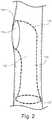
- FIG. 1shows an example of the universal fenestrated endograft 100.
- the universal fenestrated endograft 100is generally tubular in shape with body 101 extended along a longitudinal axis 102, the body being expandable and having a first end 103, a second end 104, a first wall 105, a second wall 106, and an interior passage or lumen 107 there between.
- the bodymay include openings 108 and 109 in communication with the passage at the first and second ends respectively, the openings being substantially transverse to the longitudinal axis.
- the bodymay include one or more lateral fenestrations 110 and 111 in communication with the lumen.
- the bodymay have a necked portion between the ends and may furthermore have a cannulation member 112 contained therein as shown in FIG. 3 .
- the universal fenestrated endograft 100may also be made in a bifurcated configuration, similar to that shown in FIGS. 16A-B .
- the universal fenestrated endograft 100may be made of polyester, polytetrafluoroethylene (PTFE) or any other suitable fabric.
- PTFEpolytetrafluoroethylene
- the universal fenestrated endograft 100may be reinforced or unreinforced and stented or nonstented.
- the universal fenestrated endograft 100may have one or more fenestrations or openings (reference numbers 110 and 111 in FIG. 1 ) preferably assuming a substantially circular or oval shape largely depending on the branches to be treated.
- a fenestrationmay comprise of an orifice or opening in the wall of the universal fenestrated endograft. Because the external orifices of the described fenestrated endograft have dimensions that accommodate most arterial or venous branch morphology including variable distances, angles and profiles of one or more vessels, the device is called universal fenestrated endograft.
- the renal arteriesmay branch from the aorta at the same level or at different levels.
- some arteries extending from the aortamay be directed more anteriorly while others more posteriorly.
- the presently described endograftsare designed to accommodate such variants.
- said external orificemay be wide enough to accommodate anatomical variations of the aortic arch, as well as areas of the visceral arteries in the abdominal aorta. Diameter may of the opening may vary according to the area treated, for example, larger in the aortic arch and smaller in the juxta-renal area.
- the universal fenestrationsare between about 3 and about 7 cm in diameter depending on, for example, anatomical variations and the specific target branch vessel or vessels. In a preferred embodiment, the universal fenestrations are about 5 cm in diameter. In another preferred embodiment, the universal fenestrations are about 4 cm in diameter.
- fenestrations of the described universal fenestrated endograftdo not open directly into the lumen of the universal fenestrated endograft, rather they are engaged to one or more cannulation members 112 positioned inside the lumen of the universal fenestrated endograft.
- the cannulation membermay comprise an external orifice 113, a rim 114, a cavity 115, a tubular segment 116, and an internal orifice 117.
- the external orifice 113may be of the same or different dimension to the fenestration to which it is engaged.
- the external orificeis between about 3 and about 7 cm in diameter depending on, for example, anatomical variations and the specific target branch vessel or vessels.
- the external orificeis about 5 cm in diameter.
- the external orificeis about 4 cm in diameter.
- the external orifice 113may be substantially circular or substantially oval shaped.
- the external orifice 113 and fenestrationmay be circular and smaller in diameter for the renal, celiac and superior mesenteric artery targets (e.g. 3 cm) and more oval shaped and larger for the supra-aortic vessels (e.g., 7 cm).
- the cannulation membermay take any shape; however in some embodiments, the cannulation member is substantially funnel shaped, tubular shaped and/or cylindrical shaped depending on the components.
- tubular segment 116is substantially tubular shaped.
- the orientation of the cannulation member 112 inside the universal fenestrated endograftmay be vary depending on factors, such as for example, anatomical variations in the patient blood flow preservation needs, etc.
- the longitudinal axis through the tubular segment of the cannulation membermay be directed substantially parallel to (in either direction), oblique to, or at a 90° angle to the longitudinal axis of the body of the main universal fenestrated endograft.
- cannulation members 112may be either caudally and/or cranially directed.
- the cannulation members 112a and 112bare obliquely angled to facilitate blood flow.
- the cannulation membermay be engaged to the side of the universal fenestrated endograft. As shown in FIG. 9 , the cannulation member may share one of its an entire walls with the universal fenestrated endograft, may share part of one of its walls with the universal fenestrated endograft, or may have walls that are independent of the universal fenestrated endograft and engaged at one or more attachment point 118, 119, 120.
- the tubular segment 116 of the cannulation membermay be any dimension as long as it can accommodate the instrumentation necessary for the procedure being performed, for example catheters and/or guiding elements.
- the tubular segment 116is between about 15 mm to about 20 mm in length and between about 6 mm to about 8 mm in diameter.
- the tubular segment 116should be 6 mm in diameter if the procedural target is for the renal arteries, celiac axis and superior mesenteric arteries.
- the tubular segment 116may be larger e.g. 8 mm in diameter.
- the tubular segment 116 of the cannulation member 112may be used to bridge the lumen 107 of the universal fenestrated endograft with a branch vessel 121, as is illustrated in FIG. 5 .
- the cannulation memberis of proper dimension to allow a working catheter 122 to engage the ostium 123 of a branch vessel 124, introduce a guiding element 125, measure the distance between the tubular segment of the cannulation member ( FIG. 6 ) and an initial length of a branch artery past the ostium, and place an secondary endograft (reference number 126 in FIG. 5 ) connecting the tubular segment of the cannulation member to the proximal end of the branch.
- the initial length of the branch artery past the ostium to be measuredis at between about 1.5 and 2 cm.
- implantation proceduresare similar in many aspects but may differ in various aspects.
- the proceduremay be used to treat a juxta-renal aneurysm.
- a universal fenestrated endograft with universal fenestrations for renal arteries and with an anterior scallop for the superior mesenteric arteryis placed in the aorta, oriented by anterior radio-opaque marks and deployed at the optimal level to accommodate and receive the superior mesenteric artery ostium. Radio-opaque marks may also be placed at the ends and at the level of the external orifice.
- the universal fenestrationmay be positioned to receive the renal branches.
- a self expandable endograftmay be released from the sheath releasing the partially constricting wire.
- the partially constricting wiremay be kept in position to achieve accurate positioning of the endograft.
- the internal orifice of the tubular segment of the cannulation memberis directed caudally and the internal orifice is flared to facilitate cannulation.
- a catheter with an appropriate shapeis introduced in the cannulation member through the internal orifice from below and the renal artery ostium is engaged and the artery is cannulated.
- a guiding elementis introduced in the renal artery and a marked catheter used to measure the distance between the tubular segment of the cannulation member and 2 cm inside the renal artery.
- a secondary endograftis chosen and deployed to the site to function as a bridge between the cannulation member's tubular segment and the trunk of the renal artery as shown in FIG. 5 .
- Balloon-expandable or self-expandable endograftsmay be used as shown in FIG. 12 . After measuring the length of the tubular endograft needed to bridge the endograft and the branch, the endograft is advanced into the branch and released, the endograft is molded with a balloon and a final arteriogram performed.
- the described universal fenestrated endograftsmay be used in any vessel.
- the aortait may be applied to evaluate and/or treatjuxtarenal aneurysms, abdominal aortic aneurysms, thoraco-abdominal aneurysms, aneurysms of the iliac arteries, and aneurysms of the aortic-arch.
- a fenestration of the universal fenestrated endograftmay be wide enough to cover or receive several arteries, such as the celiac axis, the superior mesenteric arteries and one or more renal arteries. Furthermore, the shape and construction of the cannulation member may be adjusted according to the number, profile, etc. of the arteries are being treated.
- the described universal fenestrated endograftsmay comprise one or more cannulation members that further comprise one or more chambers within the tubular segments of the cannulation members.
- the tubular segment of the cannulation membermay comprise multiple chambers extending longitudinally through the tubular segment to the internal orifice.
- two chambers 127 and 128may be constructed in the cannulation member 112 for cannulation of the specific branch artery target.
- the internal orifices of cannulation membersmay be directed caudally (as depicted in FIG. 3 ) or cranially (as depicted in FIG. 18 ).
- the cannulation membermay be braided or may comprise a zigzag construction to facilitate constriction of the universal fenestrated endograft with the cannulation member and delivery to a target vessel area and also to maintain integrity of form, shape, and profile once delivered to the target and expanded.
- a cannulation member 112may comprise a metal component which may be a continuation of the metal in the main universal fenestrated endograft as shown in FIGS. 10A and 10B .
- the cannulation membermay be braided, attached to the edge of the fenestration and constricted for delivery (as shown in FIGS.
- a metal component used in this mannermay comprise a skeleton, frame, or lattice that substantially forms the shape of the cannulation member 112.
- the metal componentmay be covered by, for example, Dacron, ePTFE, or the like.
- the external orifice 113may also contain the metal component. In this manner, the external orifice's shape may be substantially preserved allowing instrumentation to progress through with little concern of collapse.
- the cannulation membermay further comprise a flared internal orifice 117 located at the end of the tubular segment as shown in FIG. 2 .
- the cannulation member 112may additionally comprise a guiding element 125 attached to the cannulation member 112, for example, at the rim of the external orifice or universal fenestration. Referring to FIG.13A-B , the guiding member 125 may extend through the external orifice 113, into the cavity 115 of the cannulation member, through the tubular segment 116, and out the internal orifice 117.
- the guiding element 129may then follow inside the introducing sheath 129 and leaving from the valve 130 of the sheath or from an orifice made in the valve (as shown in FIG. 13B ).
- the guiding element 125may be a thread or a guiding element.
- the cannulation membermay contain a balloon exiting from the internal orifice of the cannulation member in the valve of the sheath.
- the universal fenestrated endograft 100will be suitable for passage of guiding elements, balloons, or other endovascular means of manipulation. It may also serve as a scaffold for the placement of devices meant to access tributaries and/or provide a conduit to them. It may serve as a scaffold for other endovascular graft materials or prostheses to perform roles of reinforcement or provide further competence of graft sections between intervening tributaries.
- the universal fenestrated endograft 100may be introduced over a catheter into an abdominal aortic aneurysm in a patient's aorta, for example.
- the universal fenestrated endograft 100is preferably fixed in a normal part of aorta proximal to the section to be repaired or excluded.
- fixationmay be in the lower thoracic aorta for all abdominal pathology and proximal to the innominate artery for the thoracic pathology, although fixation can be placed at any normal diameter aorta with suitable mural morphology for the fixation technique.
- the proximal or upstream end of the universal fenestrated endograft 100may be placed proximal or superior to any or all of the renal, hepatic and mesenteric arteries when appropriate.
- the universal fenestrated endograft and the cannulation membermay be self-expanding or it may be balloon expandable, or a combination of the two techniques may be used.
- FIGS. 3A-Bvarious embodiments are shown comprising a main universal fenestrated endograft 100 comprising a cannulating member 112.
- the cannulating member 112 shown within the universal fenestrated endograft 100 illustrated in FIG. 3Acomprises a external orifice 113, which in this embodiment is the same size as the universal fenestration, a rim 114, a cavity 115, a tubular segment 116, and an internal orifice 117.
- Internal orifice 117may be straight, tapered orflared as shown in the embodiment depicted in FIG. 2 and FIG. 3A .
- the internal orifice 117is flared to facilitate entry of instruments such as catheters into the cannulating member facilitating entry into and through the branch vessels.
- FIG. 3Bshows a cannulation member 112 with a guiding element 125 extending from the external orifice 113 and through cavity 115, tubular segment 116 and out internal orifice 117.
- FIG. 3Bshows an embodiment of cannulation member 112 in an expanded and collapsed or constricted state.
- the cannulation member 112 shown in FIGS. 3A-B and FIGS. 11A-Bis of a braided construction facilitating constriction of the cannulation member.
- FIG. 4a cranial segment of an embodiment of the universal fenestrated endograft of the present invention is shown.
- an external orifice 113 of a cannulation member 112is positioned within a first wall 105 of the main universal fenestrated endograft 100.
- external orifice 113is sufficiently large to accommodate connectivity with renal artery 132 at various positions and angles of approach.
- FIG. 4also shows a cannulation member 112 with cavity 115 and internal orifice 117 opening into the lumen of main universal fenestrated endograft 100.
- renal artery 121is connected via secondary endograft 126 to universal fenestrated endograft 100 positioned within the lumen of aorta.
- Secondary endograft 126has been positioned using cannulation member 112 such that it extends from renal artery through external orifice 113 into cavity 115 and down tubular segment 116.
- the renal arteryis depicted for illustration purposes as separate and disconnected from the endograft 100, but it will be recognized by those of ordinary skill in the art that the renal artery during actual procedural conditions is connected to the aorta and the endograft 100.
- FIG. 6an example of the method used to place secondary endograft 126 illustrated in FIG. 5 is shown.
- a catheter 122 and guiding element 125is inserted into the flared internal orifice 117 of cannulation member 112 and extends through tubular segment 116, external orifice 113, and renal artery ostium 123.
- the markings on catheter 122are used to measure the distance between tubular segment 116 and trunk of the renal artery branch. This measurement is used to guide deposit of the secondary endograft bridge shown in FIG. 5 .
- the renal arteryis depicted for illustration purposes as separate and disconnected from the endograft 100, but it will be recognized by those of ordinary skill in the art that the renal artery during actual procedural conditions is connected to the aorta and the endograft 100.
- the renal arteryis connected to endograft 100 once the secondary endograft 126 is deployed between the tubular segment and the initial segment of the branch artery.
- FIG. 7an upper segment of a universal fenestrated endograft is shown.
- a main universal fenestrated endograft 100comprises a scallop 133 which is a larger fenestration within endograft 100 for connection with superior mesenteric artery.
- the endograft 100is shown with two cannulation members 112a and 112b for connection with left and right renal arteries.
- FIG. 3also shows an aortic aneurism under repair.
- FIG. 1illustrates an example of a main universal fenestrated endograft in partially constricted form and released/expanded form. The partially constricted endograft allows changes in orientation facilitating cannulation of the branches.
- FIG. 8shows a universal fenestrated endograft 100 comprising three independent cannulation members 112a, 112b, 112c extending from a single universal fenestration or orifice 134.
- the three independent cannulation memberspair up with the superior mesenteric artery (SMA), the celiac axis (CA) and the right renal artery.
- SMAsuperior mesenteric artery
- CAceliac axis
- the embodiment illustrated in FIG. 8shows three secondary endografts 126a, 126b, 126c that have been deposited to bridge with the SMA, CA, and right renal artery using the specific cannulation member for each artery.
- FIGS. 9A-Bshows two embodiments of the cannulation member and how it engages to the universal fenestrated endograft 100.
- the cannulation member 112shares walls with the main endograft and, in the other embodiment, the cannulation member walls are independent of the walls of the main endograft except that the cannulation member may be attached at to the main endograft at attachments point 118, 119, 120.
- the attachment pointmay be at the edge of the universal fenestration.
- FIG. 10illustrates that the universal fenestrated endograft and the cannulation member may be a one piece construction wherein the cannulation member forms a part of the main body of the universal fenestrated endograft.
- fenestrated endograftsmay comprise cannulation members that are braided as shown in FIG. 11A-B and FIG. 2B to facilitate constriction or compression and delivery of the universal fenestrated endograft to the target site.
- FIG. 11shows a braided cannulation member design in compressed ( FIG. 11A ) and expanded ( FIG. 11B ) form.
- the fenestrated endograftsmay comprise cannulation members that are malleable, such that they may fit securely over an object of various sizes and profiles.
- FIG. 12shows a malleable cannulation member covering a balloon.
- the malleable cannulation membermay be compressed ( FIG. 12A ) or expanded ( FIG. 12B ) depending on the needs, size, or profile of the object.
- a malleable cannulation memberis initially compressed for deployment, and once the universal fenestrated endograft is expanded, a balloon is inflated and the cannulation member expanded.
- FIG. 14shows an embodiment depicting the universal fenestrated endograft positioned within the aortic arch.
- external orifice 113is large enough and positioned to accommodate two or more supra-aortic branches.
- the external orifice 113receives two supra-aortic branches, specifically the innominate 135 and left carotid 136 arteries.
- cannulation member 112is constructed with two chambers, 127 and 128 respectively, one for receipt of a secondary endograft 126a for an innominate arterial bridge and the other for receipt of a secondary endograft 126b for a left carotid artery bridge.
- the two chambers 127 and 128are positioned in the tubular segment 116 of cannulation member 112.
- FIG. 15shows an embodiment of the present invention depicting a universal fenestrated endograft connected with supra-aortic trunks.
- the embodiment illustrated in FIG. 15is similar to the FIG. 14 except that the subclavian artery 137 has been plugged to occlude blood flow.
- the universal fenestrated endograft of the present inventioncan be modified to cover it as well.
- FIG. 16shows an embodiment depicting a universal fenestrated endograft 100 to common iliac artery aneurysms.
- the universal fenestrated endograft 100is bifurcated and positioned in the iliac arteries.
- the main endograft in this examplecomprises a long limb 138 extending to the external iliac artery 139 and a short tubular segment 140 with a big cannulation member 112 with a flared internal orifice 117 directed toward the hypogastric artery 141.
- FIG. 16also shows a secondary endograft 126 connecting the tubular segment 140 of the cannulation member 112 with the hypogastric artery 141.
- FIGS. 17A-Bshow an embodiment of the universal fenestrated endograft for the aortic arch with preservation of the flow of the innominate and left carotid trunks.
- the cannulation membersare obliquely angled to facilitate blood flow.
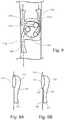
- FIGS. 18A-Bshow an embodiment depicting a universal fenestrated endograft for the juxta-renal artery.
- the main universal fenestrated endograft 100comprises an external orifice 113 which is designed to accommodate renal arteries extending from the abdominal aorta, a cannulation member 112 with a tubular segment 116, and an internal orifice 117.
- a scallop 134for entry of the superior mesenteric artery and connection to the lumen of the main universal fenestrated endograft 100.
- the cannulation members 112a and 112bare directed cranially for top entry.
- FIGS. 19A-Bshow an embodiment depicting a universal fenestrated endograft for the juxta-renal artery with three cannulation members for the celiac trunk, superior mesenteric and renal arteries.
- a universal branched endograft deviceincludes a main tubular body/cylinder.
- the main tubular body/cylinderis about 6 cm in length.
- the main tubular body/cylindermay have a variable diameter.
- a second cylinder/lumenmay be placed inside the main cylinder.
- the second cylinder/lumenis about 15 cm in length and about 18 mm in diameter.
- Inside the main cylinderthere may be one or more smaller branch lumens/cylinders following the same longitudinal axis as the main cylinder.
- the branch lumens/cylindersare the same diameter. In a preferred embodiment, however, the branch lumens/cylinders are of different diameters.
- a universal branched endograftcomprising four branch lumens/cylinders, two are 6 mm in diameter and the remaining two are 8 mm in diameter.
- the four small cylindersare placed radially along the circumference of the main cylinder of the 15 cm long cylinder.
- diameters of the branchesare made standard as well as lengths, with the diameter of the main cylinder being a selectable variable for use in particular anatomy.
- a proximal segmenthas no independent wall and shares the outer wall of the main and short cylinders or, in alternative embodiments, just has a fabric wall.
- the outer walls of the short segments together with the inner wall of the main endograftcreate a channel for the aortic extension.
- an inner surface of the short and 15 cm long cylindershave the metal stent-like skeleton.
- An endograftcouples to the skeleton, and is locked into place.
- the metal and fabricare kept together with sutures or different glues.
- a membranecan be used to put together the metal and the fabric.
- the wallis solely fabric and has two metallic rings at the ends to maintain patency.
- the wall of the cylinderscan be, in general, a combination of fabric and metal to make up the standard wall of an endograft.
- the metalcan be nitinol, nobaltchromium or stainless steel or any suitable material having similar characteristics.
- Metal barbscan be part of the metal skeleton and protrude outside the main cylinder. Radio-opaque marks can be placed anteriorly and on the left lower quadrant for orientation.
- cylinderscan be placed inside the main cylinder and the interstices filled with compressible texturized fabric.
- the fabriccan be made of polyester or ePTFE. But generally, any membrane or fabric-like biocompatible, non-absorbable material can be used. Alternatively, no interstices may be created and all or some walls may be shared among the cylinders.
- the different cylinderscan be independent of one another or they can share walls with adjacent cylinder(s). In the case of independent walls, spaces among the different components can be filled with soft and compressible fabric, which seal the interstices.
- the four small cylindersare joined and are attached along the periphery of the main cylinder cavity.
- the remaining volume of the cavityafter attaching the joined four cylinders, constitutes the cavity of the 15 cm long cylinder which in the initial 6 cm of length share walls with the inner main cylinder and the outer surface of the joined four small cylinders. Accordingly, the upper part of the 15 cm long cylinder uses the outer wall of the small and main cylinders. At the caudal edge of the main endograft, the cavity continues with the wall of the 15 cm long cylinder that extends cylindrically for the remaining 9 cm.
- walls of the small cylindersare solely constructed of fabric, however, with the incorporation of a row of metal at both ends of the cylinders to keep the cavity open.
- the 15 cm long cylinderis configured as 9 cm of the main cylinder, with its wall being solely fabric for the initial 6 cm and fabric with metal in the following 9 cm.
- the upper part of the 15 cm long cylindershares a wall in the initial 4 cm and in the last 2 cm has its own fabric wall.
- the proximal 6 cm long segmentcan have an irregular shape which is the volume of the cavity of the main cylinder minus the area occupied by the short cylinders.
- the proximal cavity of the 15 cm long cylindercontinues with the now circular section tube with metal reinforcing the fabric.
- the small cylindersare kept open with a stent-like metal skeleton.
- Metal in the small cylinders in the form of "zigs"are located in the inner surface of the tube in order to interact with the metal skeleton of the connecting tube endograft which lies outside.
- Zigs of the small cylinder and connecting endograft (tube)match with each other and lock the connection between them.
- Eventually small cylindersare fabricated with fabric alone and two rings are applied at the ends to keep them open.
- the diameter of the universal branched endograftmay be selected by adding 15% of the diameter of the normal aorta above the aneurysm.
- Implanting procedures of the universal branched endograftsmay generally comprise the following steps. Implantation of the universal branched endograft may be performed from the common femoral artery percutaneously or through a cut down. The delivery system containing the universal branched endograft is advanced over a guiding element to reach the area of deployment proximal to the target, e.g. aneurysm. Anterior radio-opaque marks or other technique may assist to orient the device properly, and after checking the right orientation, the universal branched endograft is deployed. Once deployed to the desired position, the channels may be cannulated and the branches cannulated one by one. A catheter and guiding element may locate the lumen of the visceral branches.
- each secondary endograftmay be deployed and molded with a balloon.
- the initial 15 mm of the target branchis covered by the secondary endograft.
- Initial placement of the universal endograftmay be carried out from the femoral artery. Cannulation of the channels and branches may be carried out from the upper extremities.
- a guiding elementis inserted from the femoral artery to the thoracic aortic lumen using the wire as a guide.
- a sheath containing the endograftis advanced up to the desired position and deployed using radio-opaque marks as references.
- the branchesare cannulated from above and catheters introduced into the visceral branches.
- secondary endograftsare deployed bridging the universal branched endograft and the aortic branches.
- each small cylindermay be cannulated and extended via a tube endograft inside the visceral branches.
- the medially located small cylindersmay be used to extend into the celiac axis and the superior mesenteric arteries.
- the lateral small cylindersmay be used to extend into both renal arteries.
- the main cylindermay be fixed to the aortic wall by friction and by active fixation defined by barbs, which are part of the metallic component of the endograft.
- a non-compliant balloonmay be used to insure good apposition of the connecting endografts and the short cylinders and the visceral arteries. Additional bare stents can be used to secure apposition of the segments connected.
- a final arteriogrammay be performed to rule out any endoleaks.
- the universal branched endografthas four endograft extensions 142a, 142b, 142c, 142d from four adjacent cylinders (not shown).
- the four endograft extensionsare to the left renal, celiac, superior mesenteric, and right renal arteries respectively.
- FIG. 21an embodiment of the universal branched endograft of the present invention is shown.
- the four adjacent cylinders 143a, 143b, 143c, and 143dare shown within the main tubular body/cylinder 144 and placed radially along the circumference of the main cylinder.
- a second cylinder/lumen 145is shown extending from the main cylinder.
Landscapes
- Health & Medical Sciences (AREA)
- Engineering & Computer Science (AREA)
- Biomedical Technology (AREA)
- Heart & Thoracic Surgery (AREA)
- Public Health (AREA)
- Transplantation (AREA)
- Cardiology (AREA)
- Veterinary Medicine (AREA)
- Oral & Maxillofacial Surgery (AREA)
- Vascular Medicine (AREA)
- Life Sciences & Earth Sciences (AREA)
- Animal Behavior & Ethology (AREA)
- General Health & Medical Sciences (AREA)
- Gastroenterology & Hepatology (AREA)
- Pulmonology (AREA)
- Prostheses (AREA)
- Media Introduction/Drainage Providing Device (AREA)
Description
- The present invention relates generally to endovascular grafts ("endografts") for evaluation and repair of damaged or aneurismal blood vessels. More particularly, it relates to universal branched endografts for repair of blood vessels with branches, methods for repairing blood vessels and for making connection with one or more branches.
- Endografts are artificial grafts typically composed of metal and fabric that are placed inside the arteries or veins to treat aneurysms, dissections, stenosis or injuries. Endografts cover the diseased segments of the vessels, and typically the ends of endografts are positions against non-diseased portions. Placement of endografts typically is done from a remote site, usually the common femoral artery.
- Since the first English publication of a study describing the clinical application of an endograft to treat an aneurysm (Annals of Vascular Surgery 1991; 5:491), endografting has expanded worldwide. In 2010, approximately 107,000 endografts were applied for aortic aneurysms globally.
- In many cases, the damaged or defected portion of the vessel being treated may include branches. For example, in the case of the abdominal aorta, there are at least three branch vessels, including the celiac, mesenteric, and renal arteries, leading to various other organs. Thus, when the damaged portion of the vessel includes one or more of these branch vessels, some accommodation must be made to ensure that the endograft does not block or hinder blood flow through the branch vessel.
- Attempts to maintain blood flow to branch vessels have included providing one or more fenestrations or holes in the side wall of the endograft. Other attempts have included providing an endograft in which the branch vessel portion of the vessel is spanned by wires or the like. Generally, this treatment involves aligning the fenestrations with the branch vessels, which may extend approximately at right angles on both sides from the aorta.
- In many cases, the vasculature is not symmetric. In addition, even with symmetrical vasculature, physiological forces may cause a previously placed branch vessel endograft to shift causing the position of the fenestration to offset from the branch. In other instances, the diseased vasculature may extend into the branch vessel itself.
- When treating a vessel with an endograft, it is sometimes beneficial to deploy a secondary endograft extending from the primary endograft to a side branch vessel so that the blood flow into the branch vessel is not impeded. Branch vessel endografts can form a connection to primary endografts through fenestrations to complete the prosthesis. Furthermore, some aneurysms extend into the branch vessels in both the thoracic and abdominal aorta. Deploying prostheses with prosthetic branches into these vessels may help prevent expansion and/or rupture of these aneurysms.
US2005/0010277A1 discloses a modular stent-graft for endovascular repair of aortic arch aneurysms and dissections.- Limitations for the use of endografts in the aorta are related to short or angulated landing zones. When visceral or supra-aortic branches split off from an aneurysm, endografts need to have fenestrations or branches similar to those used in short proximal necks (landing zones). When fenestrations or branches are needed, custom-made devices are constructed that take into account distances and angles indicated in aortic images of a patient. Custom made devices have been constructed until now with good results, but such devices are expensive and take a relatively long time to manufacture. Further, the custom nature of the device adds complexity to the procedure of implantation, due to, among other reasons, inconsistent designs. Additionally, it is frequently difficult to accurately and precisely guide the instrumentation needed to cannulate the branch to the branch ostium. Thus, it would be beneficial for an endograft to have structures connecting the lumen of the endograft to the fenestration and the branch artery ostium; thus facilitating cannulation of the branch arteries and a continuation of procedures without extra incisions or unnecessary arterial approaches. Accordingly, there is need to address these issues.
- Insofar as the terms "invention" and/or "embodiment" are used in the following, and/or features are presented as being optional, this should be interpreted in such a way that the only protection sought is that of the invention as claimed.
- In order to facilitate the procedure and provide an "off the shelf" device, the following endografts were developed. The universal endografts described could be used for all, or most, of the patients with similar conditions.
- There is now described theuniversal fenestrated endograft relates to an endograft with orifices or fenestrations to facilitate connection between an endograft placed in an artery or vessel and branches of other arteries and vessels. In one embodiment, fenestrations are located within the walls of an endograft. In another embodiment, the endograft may additional comprise cannulation members engaged to said fenestrations. Cannulation members generally comprise an external orifice, a cavity, a tubular segment, and an internal orifice. The external orifice may further comprise an inner and outer rim. In one embodiment, the internal orifice of the cannulation member from the lumen of the universal fenestrated endograft. This direct connection from the lumen of the universal fenestrated endograft to the branch artery facilitates efficient treatment of branch arteries without the need of extra incision or arterial approaches other than femoral access.
- As the external orifice of the described universal fenestrated endograft has dimensions that accommodate most arterial or venous branch morphology, the device is called a universal fenestrated endograft. For example, in one embodiment, the external orifice of the cannulation member may be wide enough to accommodate anatomical variations of the aortic arch, as well as areas of the visceral arteries in the abdominal aorta.
- In one embodiment of the described universal fenestrated endograft, openings or fenestrations may cover all of the variations of the site of the extensions of the branches of the vessels. The tubular segment of the cannulation member may connect to the proximal lumen of the branch vessel through an endograft interposed between them. Furthermore, the inner orifice of the cannulation member may have a flared end to facilitate cannulation.
- In another embodiment of the universal fenestrated endograft, , fenestrations and the corresponding cannulation member may be constructed as a part of the main universal fenestrated endograft wherein the cannulation member is independent or shares segments between the cannulation member and the endograft.
- Catheters and other instrumentation may be introduced in the tubular segment of the cannulation member reaching the cavity of the cannulation member and the fenestration. Ostia of the branch vessels may be cannulated and connection with a tubular endograft is established between the tubular segment of the cannulation member and the trunk of the branch vessel, for example, the initial about 1.5 to 2 cm of the vessel.
- In another aspect of the described universal fenestrated endograft, when the cannulation member accommodates multiple branches, in one embodiment, procedures may be performed from different chambers constructed within the tubular segment of the cannulation member to the different vessel branches. In another embodiment, independent cannulation members may be constructed wherein each cannulation member uses the same universal fenestration to access the different vessel branches.
- In another aspect of the described universal fenestrated endograft walls of the cannulation member may be a part of the endograft, constitute a braided cannulation member attached to the edge of the fenestration, or make up a malleable cannulation member attached to the edge of the fenestration, wherein, in this latter case, a balloon of very low profile is placed inside the cannulation member and the cannulation member is compressed and collapsed over the balloon.
- In another aspect of the described universal fenestrated endograft, guiding elements, for example, guide wires or fabric threads, are used to guide catheters inside the cannulation member. Wires and threads may be attached outside the fenestration, pass the fenestration and come out through an orifice of the valve of the introducer sheath.
- In another aspect of the described universal fenestrated endograft, segments of the aorta or iliac arteries in which universal fenestrated endograft could be used include: an aortic arch; visceral segment of the abdominal aorta; and iliac bifurcation in cases of iliac aneurysms.
- Another embodiment describes a universal fenestrated endograft having a body extended along a longitudinal axis, the body being expandable and having a first end, a second end, a first wall, a second wall, and an interior passage or lumen there between when expanded. The body may include openings in communication with the passage at the first and second ends, the openings being substantially transverse to the longitudinal axis. The body may include one or more lateral fenestrations in communication with the lumen at the first or second end. The body may have a necked portion between the ends and may further have a cannulation member contained therein.
- In one embodiment, the body, including the cannulation member, has a braided construction.
- In another embodiment, the body may comprise a scallop for receiving a branch artery, for example, the superior mesenteric artery. For example, a scallop may be used to prevent coverage of the superior mesenteric artery when a universal fenestrated endograft is used to connect the renal arteries.
- There is also described, a method for repairing a patient's blood vessel. In the method a universal fenestrated endograft is obtained, as described herein and implanted to affect a therapeutic result.
- Referring now to theuniversal branched endograft of the present invention, in one embodiment of the invention a universal branched endograft device comprises a tubular body with a main lumen and four branch lumens, with a large branch extending from the body. The large branch may be in fluid communication with the main lumen. The four branch lumens may be positioned about a circumference of the tubular body, and each configured to connect to a tubular endograft.
- In one aspect of the first embodiment of the universal branched endograft, each branch lumen can include a tubular extension configured for connecting to a target branch artery.
- In another aspect of the embodiment of the universal branched endograft, the large branch can be configured to connect with a distal aorta or an iliac artery.
- In another aspect of the embodiment of the universal branched endograft, each lumen includes a stent-like frame.
- In another aspect of the embodiment of the universal branched endograft, the tubular body is at least about 6 cm in length.
- There is also described, a method for using the universal branched device. In the method, the universal branched device may be obtained and implanted within a patient to treat a thoraco-abdominal aneurysm.
- In one aspect of the described method, a guiding element is fed from a femoral cut down to the thoracic aorta. The universal branched endograft with aortic extensions can be put into place via the guiding element, and the universal branched endograft is cannulated to a superior mesenteric artery (SMA), celiac axis and renal arteries.
- There will now be described with reference to the accompanying drawings universal fenestrated endografts and embodiment[s] of the invention, namely universal brached endografts, in which:
FIG. 1A-C shows a universal fenestrated endograft (constricted and expanded) with two lateral universal fenestrations and a scallop at the first end of the endograft to prevent coverage of a branch artery.FIG. 1C shows an exterior view of a lateral fenestration covering four branch vessel positions.FIG. 2 shows an embodiment of a cannulation member and its components.FIGS. 3A-B shows various embodiments, including a universal fenestrated endograft with two cannulation members engaged to a lateral universal fenestration.FIG. 1B shows a braided cannulation member in an expanded and constricted state.FIG. 4 shows a cranial segment of a universal fenestrated endograft depicting a scallop for the superior mesenteric artery and a cannulation member for renal artery coverage.FIG. 5 shows a cannulation member with an endograft bridge to the renal artery.FIG. 6 shows a cannulation member, renal artery, and a catheter and guiding element cannulating the branch artery.FIG. 7 shows an upper segment of the universal fenestrated endograft with two lateral cannulation members covering the renal arteries and a scallop for the superior mesenteric artery. Also shown is an aortic aneurysm.FIG. 8 shows universal fenestrated endograft with three independent cannulation members sharing a single external orifice and fenestration covering three branch vessels, the superior mesenteric artery (SMA), the celiac axis (CA) and the right renal artery.FIGS. 9A-B illustrates embodiments of how the cannulation member may engage the universal fenestrated endograft.FIG. 8A shows a cannulation member sharing walls with the main endograft.FIG. 8B shows a cannulation member that engages the wall at specific attachment points, for example the edge of the fenestration or external orifice.FIGS. 10A-B shows a one piece cannulation member and main body.FIGS. 11A-B shows a braided cannulation member in constricted (FIG. 10A ) and expanded (FIG. 10B ) form.FIGS. 12A-B shows a malleable cannulation member comprising a balloon with balloon contracted (FIG. 9A ) and expanded (FIG. 9B ).FIGS. 13A-B shows a guiding element engaged to the outside of the universal fenestrated endograft, entering through a lateral fenestration into a cannulation member, into the lumen of the endograft and exiting from an orifice of the valve of the sheath.FIGS. 14-15 show embodiments of a universal fenestrated endograft applied in an aortic arch.FIGS. 16A-B shows another application of the universal fenestrated endograft to common iliac artery aneurysms.FIGS. 17A-B show different views of a universal fenestrated endograft for the aortic arch with preservation of the flow of the innominate and left carotid trunks.FIGS. 18A-B show different views of a universal fenestrated endograft for the juxta-renal aorta artery.FIGS. 19A-B show different views a universal fenestrated endograft for the juxta-renal aorta artery with cylinders for the celiac trunk, superior mesenteric and renal arteries.FIGS. 20 shows an embodiment of a universal branched endograft of the present invention with four endograft extensions to the left renal, celiac, superior mesenteric, and right renal arterial branches.FIGS. 21A-C shows an embodiment of the universal branched endograft of the present invention.- Further scope of applicability of the present invention will become apparent from the detailed description given herein. However, it should be understood that the detailed description and examples provided herein, while indicating embodiments of the invention, are given by way of illustration only, since various changes and modifications within the spirit and scope of the invention will become apparent to those skilled in the art.
- The present invention takes the form of an endovascular graft ("endograft") for use in the common catheter-based minimally-invasive surgical techniques, for example, in the examination and repair of the thoracic or abdominal aorta.
- There is now described the universal fenestrated endograft,
FIG. 1 shows an example of the universalfenestrated endograft 100. The universalfenestrated endograft 100 is generally tubular in shape withbody 101 extended along alongitudinal axis 102, the body being expandable and having afirst end 103, asecond end 104, afirst wall 105, asecond wall 106, and an interior passage orlumen 107 there between. The body may includeopenings lateral fenestrations cannulation member 112 contained therein as shown inFIG. 3 . If desired, the universalfenestrated endograft 100 may also be made in a bifurcated configuration, similar to that shown inFIGS. 16A-B . The universalfenestrated endograft 100 may be made of polyester, polytetrafluoroethylene (PTFE) or any other suitable fabric. The universalfenestrated endograft 100 may be reinforced or unreinforced and stented or nonstented. - As discussed above, the universal
fenestrated endograft 100 may have one or more fenestrations or openings (reference numbers FIG. 1 ) preferably assuming a substantially circular or oval shape largely depending on the branches to be treated. A fenestration may comprise of an orifice or opening in the wall of the universal fenestrated endograft. Because the external orifices of the described fenestrated endograft have dimensions that accommodate most arterial or venous branch morphology including variable distances, angles and profiles of one or more vessels, the device is called universal fenestrated endograft. For example, the renal arteries may branch from the aorta at the same level or at different levels. Similarly, some arteries extending from the aorta may be directed more anteriorly while others more posteriorly. The presently described endografts are designed to accommodate such variants. For example, in one embodiment, said external orifice may be wide enough to accommodate anatomical variations of the aortic arch, as well as areas of the visceral arteries in the abdominal aorta. Diameter may of the opening may vary according to the area treated, for example, larger in the aortic arch and smaller in the juxta-renal area. In one embodiment, the universal fenestrations are between about 3 and about 7 cm in diameter depending on, for example, anatomical variations and the specific target branch vessel or vessels. In a preferred embodiment, the universal fenestrations are about 5 cm in diameter. In another preferred embodiment, the universal fenestrations are about 4 cm in diameter. - Referring to
FIG. 3A , in some embodiments, fenestrations of the described universal fenestrated endograft do not open directly into the lumen of the universal fenestrated endograft, rather they are engaged to one ormore cannulation members 112 positioned inside the lumen of the universal fenestrated endograft. Referring now toFIG. 2 , the cannulation member may comprise anexternal orifice 113, arim 114, acavity 115, atubular segment 116, and aninternal orifice 117. Theexternal orifice 113 may be of the same or different dimension to the fenestration to which it is engaged. For example, in one embodiment, the external orifice is between about 3 and about 7 cm in diameter depending on, for example, anatomical variations and the specific target branch vessel or vessels. In a preferred embodiment, the external orifice is about 5 cm in diameter. In another preferred embodiment, the external orifice is about 4 cm in diameter. In some embodiments, theexternal orifice 113 may be substantially circular or substantially oval shaped. As an example, theexternal orifice 113 and fenestration may be circular and smaller in diameter for the renal, celiac and superior mesenteric artery targets (e.g. 3 cm) and more oval shaped and larger for the supra-aortic vessels (e.g., 7 cm). - The cannulation member may take any shape; however in some embodiments, the cannulation member is substantially funnel shaped, tubular shaped and/or cylindrical shaped depending on the components. For example, in some embodiments,
tubular segment 116 is substantially tubular shaped. The orientation of thecannulation member 112 inside the universal fenestrated endograft may be vary depending on factors, such as for example, anatomical variations in the patient blood flow preservation needs, etc. For example, the longitudinal axis through the tubular segment of the cannulation member may be directed substantially parallel to (in either direction), oblique to, or at a 90° angle to the longitudinal axis of the body of the main universal fenestrated endograft. In some embodiments,cannulation members 112 may be either caudally and/or cranially directed. - For example, in procedures involving the aortic arch and carotid/innominate target branches, it may be beneficial to position
external orifice 113 andcannulation member 112 in general such to prevent retrograde blood flow caused by extreme angles of approach. Thus, in the embodiment illustrated inFIG.17A-B , thecannulation members - As described above, the cannulation member may be engaged to the side of the universal fenestrated endograft. As shown in
FIG. 9 , the cannulation member may share one of its an entire walls with the universal fenestrated endograft, may share part of one of its walls with the universal fenestrated endograft, or may have walls that are independent of the universal fenestrated endograft and engaged at one ormore attachment point - The
tubular segment 116 of the cannulation member may be any dimension as long as it can accommodate the instrumentation necessary for the procedure being performed, for example catheters and/or guiding elements. For example, in some embodiments, thetubular segment 116 is between about 15 mm to about 20 mm in length and between about 6 mm to about 8 mm in diameter. For example, in one embodiment, thetubular segment 116 should be 6 mm in diameter if the procedural target is for the renal arteries, celiac axis and superior mesenteric arteries. For the larger supra-aortic branches, thetubular segment 116 may be larger e.g. 8 mm in diameter. - The
tubular segment 116 of thecannulation member 112 may be used to bridge thelumen 107 of the universal fenestrated endograft with abranch vessel 121, as is illustrated inFIG. 5 . Referring now toFIG. 6 , in one embodiment, the cannulation member is of proper dimension to allow a workingcatheter 122 to engage theostium 123 of abranch vessel 124, introduce a guidingelement 125, measure the distance between the tubular segment of the cannulation member (FIG. 6 ) and an initial length of a branch artery past the ostium, and place an secondary endograft (reference number 126 inFIG. 5 ) connecting the tubular segment of the cannulation member to the proximal end of the branch. In some embodiments, the initial length of the branch artery past the ostium to be measured is at between about 1.5 and 2 cm. - In some embodiments, implantation procedures are similar in many aspects but may differ in various aspects. For example, the procedure may be used to treat a juxta-renal aneurysm. For example, a universal fenestrated endograft with universal fenestrations for renal arteries and with an anterior scallop for the superior mesenteric artery (as shown in
FIG. 7 ) is placed in the aorta, oriented by anterior radio-opaque marks and deployed at the optimal level to accommodate and receive the superior mesenteric artery ostium. Radio-opaque marks may also be placed at the ends and at the level of the external orifice. The universal fenestration may be positioned to receive the renal branches. At this point, a self expandable endograft may be released from the sheath releasing the partially constricting wire. Alternatively the partially constricting wire may be kept in position to achieve accurate positioning of the endograft. The internal orifice of the tubular segment of the cannulation member is directed caudally and the internal orifice is flared to facilitate cannulation. A catheter with an appropriate shape is introduced in the cannulation member through the internal orifice from below and the renal artery ostium is engaged and the artery is cannulated. A guiding element is introduced in the renal artery and a marked catheter used to measure the distance between the tubular segment of the cannulation member and 2 cm inside the renal artery. A secondary endograft is chosen and deployed to the site to function as a bridge between the cannulation member's tubular segment and the trunk of the renal artery as shown inFIG. 5 . Balloon-expandable or self-expandable endografts may be used as shown inFIG. 12 . After measuring the length of the tubular endograft needed to bridge the endograft and the branch, the endograft is advanced into the branch and released, the endograft is molded with a balloon and a final arteriogram performed. - The described universal fenestrated endografts may be used in any vessel. For example, in the case of the aorta, it may be applied to evaluate and/or treatjuxtarenal aneurysms, abdominal aortic aneurysms, thoraco-abdominal aneurysms, aneurysms of the iliac arteries, and aneurysms of the aortic-arch.
- As described above, a fenestration of the universal fenestrated endograft may be wide enough to cover or receive several arteries, such as the celiac axis, the superior mesenteric arteries and one or more renal arteries. Furthermore, the shape and construction of the cannulation member may be adjusted according to the number, profile, etc. of the arteries are being treated.
- The described universal fenestrated endografts may comprise one or more cannulation members that further comprise one or more chambers within the tubular segments of the cannulation members. In one embodiment, the tubular segment of the cannulation member may comprise multiple chambers extending longitudinally through the tubular segment to the internal orifice. For example, as shown in
FIGS. 14 and15 , if two branch arteries are covered, twochambers cannulation member 112 for cannulation of the specific branch artery target. As described previously, the internal orifices of cannulation members may be directed caudally (as depicted inFIG. 3 ) or cranially (as depicted inFIG. 18 ). - In some embodiments, (for example, as shown in
FIG. 3B ), the cannulation member may be braided or may comprise a zigzag construction to facilitate constriction of the universal fenestrated endograft with the cannulation member and delivery to a target vessel area and also to maintain integrity of form, shape, and profile once delivered to the target and expanded. In some embodiments, acannulation member 112 may comprise a metal component which may be a continuation of the metal in the main universal fenestrated endograft as shown inFIGS. 10A and 10B . The cannulation member may be braided, attached to the edge of the fenestration and constricted for delivery (as shown inFIGS. 3 and11 ) and/or may be malleable and constricted over a low profile balloon (as shown inFIG. 12 ). A metal component used in this manner may comprise a skeleton, frame, or lattice that substantially forms the shape of thecannulation member 112. The metal component may be covered by, for example, Dacron, ePTFE, or the like. It will be recognized that theexternal orifice 113 may also contain the metal component. In this manner, the external orifice's shape may be substantially preserved allowing instrumentation to progress through with little concern of collapse. - In some embodiments, the cannulation member may further comprise a flared
internal orifice 117 located at the end of the tubular segment as shown inFIG. 2 . As shown inFIGS. 3B and13A , thecannulation member 112 may additionally comprise a guidingelement 125 attached to thecannulation member 112, for example, at the rim of the external orifice or universal fenestration. Referring toFIG.13A-B , the guidingmember 125 may extend through theexternal orifice 113, into thecavity 115 of the cannulation member, through thetubular segment 116, and out theinternal orifice 117. The guidingelement 129 may then follow inside the introducingsheath 129 and leaving from thevalve 130 of the sheath or from an orifice made in the valve (as shown inFIG. 13B ). In one embodiment, the guidingelement 125 may be a thread or a guiding element. In similar manner, the cannulation member may contain a balloon exiting from the internal orifice of the cannulation member in the valve of the sheath. - The universal
fenestrated endograft 100 will be suitable for passage of guiding elements, balloons, or other endovascular means of manipulation. It may also serve as a scaffold for the placement of devices meant to access tributaries and/or provide a conduit to them. It may serve as a scaffold for other endovascular graft materials or prostheses to perform roles of reinforcement or provide further competence of graft sections between intervening tributaries. - The universal
fenestrated endograft 100 may be introduced over a catheter into an abdominal aortic aneurysm in a patient's aorta, for example. The universalfenestrated endograft 100 is preferably fixed in a normal part of aorta proximal to the section to be repaired or excluded. For example, fixation may be in the lower thoracic aorta for all abdominal pathology and proximal to the innominate artery for the thoracic pathology, although fixation can be placed at any normal diameter aorta with suitable mural morphology for the fixation technique. The proximal or upstream end of the universalfenestrated endograft 100 may be placed proximal or superior to any or all of the renal, hepatic and mesenteric arteries when appropriate. - The universal fenestrated endograft and the cannulation member may be self-expanding or it may be balloon expandable, or a combination of the two techniques may be used.
- Referring now to
FIGS. 3A-B , various embodiments are shown comprising a main universalfenestrated endograft 100 comprising a cannulatingmember 112. The cannulatingmember 112 shown within the universalfenestrated endograft 100 illustrated inFIG. 3A comprises aexternal orifice 113, which in this embodiment is the same size as the universal fenestration, arim 114, acavity 115, atubular segment 116, and aninternal orifice 117.Internal orifice 117 may be straight, tapered orflared as shown in the embodiment depicted inFIG. 2 andFIG. 3A . Preferably, theinternal orifice 117 is flared to facilitate entry of instruments such as catheters into the cannulating member facilitating entry into and through the branch vessels. - The embodiment shown in
FIG. 3B shows acannulation member 112 with a guidingelement 125 extending from theexternal orifice 113 and throughcavity 115,tubular segment 116 and outinternal orifice 117.FIG. 3B shows an embodiment ofcannulation member 112 in an expanded and collapsed or constricted state. Thecannulation member 112 shown inFIGS. 3A-B andFIGS. 11A-B is of a braided construction facilitating constriction of the cannulation member. - Referring now to
FIG. 4 , a cranial segment of an embodiment of the universal fenestrated endograft of the present invention is shown. Depicted inFIG. 4 is ascallop 131 for the superior mesenteric artery (SMA), as well as a rightrenal artery 132 in various positions withostia 133 a, b, c, d exposed to view. In this example, anexternal orifice 113 of acannulation member 112 is positioned within afirst wall 105 of the main universalfenestrated endograft 100. Here,external orifice 113 is sufficiently large to accommodate connectivity withrenal artery 132 at various positions and angles of approach.FIG. 4 also shows acannulation member 112 withcavity 115 andinternal orifice 117 opening into the lumen of main universalfenestrated endograft 100. - Referring now to
FIG. 5 , an embodiment illustrating acannulation member 112 connection to therenal artery 121 is shown. In this embodiment,renal artery 121 is connected viasecondary endograft 126 to universalfenestrated endograft 100 positioned within the lumen of aorta.Secondary endograft 126 has been positioned usingcannulation member 112 such that it extends from renal artery throughexternal orifice 113 intocavity 115 and downtubular segment 116. In this Figure the renal artery is depicted for illustration purposes as separate and disconnected from theendograft 100, but it will be recognized by those of ordinary skill in the art that the renal artery during actual procedural conditions is connected to the aorta and theendograft 100. - Referring now to
FIG. 6 , an example of the method used to placesecondary endograft 126 illustrated inFIG. 5 is shown. In this Figure, acatheter 122 and guidingelement 125 is inserted into the flaredinternal orifice 117 ofcannulation member 112 and extends throughtubular segment 116,external orifice 113, andrenal artery ostium 123. The markings oncatheter 122 are used to measure the distance betweentubular segment 116 and trunk of the renal artery branch. This measurement is used to guide deposit of the secondary endograft bridge shown inFIG. 5 . In this Figure the renal artery is depicted for illustration purposes as separate and disconnected from theendograft 100, but it will be recognized by those of ordinary skill in the art that the renal artery during actual procedural conditions is connected to the aorta and theendograft 100. The renal artery is connected to endograft 100 once thesecondary endograft 126 is deployed between the tubular segment and the initial segment of the branch artery. - Referring now to
FIG. 7 an upper segment of a universal fenestrated endograft is shown. In this embodiment, the intersection of the abdominal aorta, the superior mesenteric artery, and the left and right renal arteries is illustrated. A main universalfenestrated endograft 100 comprises ascallop 133 which is a larger fenestration withinendograft 100 for connection with superior mesenteric artery. Theendograft 100 is shown with twocannulation members FIG. 3 also shows an aortic aneurism under repair. - Fenestrated endografts are commonly inserted and positioned within a vessel in a constricted form. Once adjusted to proper position, the ends of the endograft are released in sequential order and attached to the walls of the vessel.
FIG. 1 illustrates an example of a main universal fenestrated endograft in partially constricted form and released/expanded form. The partially constricted endograft allows changes in orientation facilitating cannulation of the branches. FIG. 8 shows a universalfenestrated endograft 100 comprising threeindependent cannulation members orifice 134. In this embodiment, the three independent cannulation members pair up with the superior mesenteric artery (SMA), the celiac axis (CA) and the right renal artery. The embodiment illustrated inFIG. 8 shows threesecondary endografts FIGS. 9A-B shows two embodiments of the cannulation member and how it engages to the universalfenestrated endograft 100. In one embodiment, thecannulation member 112 shares walls with the main endograft and, in the other embodiment, the cannulation member walls are independent of the walls of the main endograft except that the cannulation member may be attached at to the main endograft atattachments point FIG. 10 illustrates that the universal fenestrated endograft and the cannulation member may be a one piece construction wherein the cannulation member forms a part of the main body of the universal fenestrated endograft.- In another embodiment of the present invention, fenestrated endografts may comprise cannulation members that are braided as shown in
FIG. 11A-B andFIG. 2B to facilitate constriction or compression and delivery of the universal fenestrated endograft to the target site.FIG. 11 shows a braided cannulation member design in compressed (FIG. 11A ) and expanded (FIG. 11B ) form. - In another described embodiment, the fenestrated endografts may comprise cannulation members that are malleable, such that they may fit securely over an object of various sizes and profiles. For example,
FIG. 12 shows a malleable cannulation member covering a balloon. The malleable cannulation member may be compressed (FIG. 12A ) or expanded (FIG. 12B ) depending on the needs, size, or profile of the object. In one embodiment, a malleable cannulation member is initially compressed for deployment, and once the universal fenestrated endograft is expanded, a balloon is inflated and the cannulation member expanded. FIG. 14 shows an embodiment depicting the universal fenestrated endograft positioned within the aortic arch. In this embodiment,external orifice 113 is large enough and positioned to accommodate two or more supra-aortic branches. For example, inFIG. 14 , theexternal orifice 113 receives two supra-aortic branches, specifically the innominate 135 and left carotid 136 arteries. In this embodiment,cannulation member 112 is constructed with two chambers, 127 and 128 respectively, one for receipt of asecondary endograft 126a for an innominate arterial bridge and the other for receipt of asecondary endograft 126b for a left carotid artery bridge. In this embodiment, the twochambers tubular segment 116 ofcannulation member 112.FIG. 15 shows an embodiment of the present invention depicting a universal fenestrated endograft connected with supra-aortic trunks. The embodiment illustrated inFIG. 15 is similar to theFIG. 14 except that thesubclavian artery 137 has been plugged to occlude blood flow. Alternatively, if the subclavian blood flow needs to be preserved, the universal fenestrated endograft of the present invention can be modified to cover it as well.FIG. 16 shows an embodiment depicting a universalfenestrated endograft 100 to common iliac artery aneurysms. In this embodiment, the universalfenestrated endograft 100 is bifurcated and positioned in the iliac arteries. The main endograft in this example comprises along limb 138 extending to the externaliliac artery 139 and ashort tubular segment 140 with abig cannulation member 112 with a flaredinternal orifice 117 directed toward thehypogastric artery 141.FIG. 16 also shows asecondary endograft 126 connecting thetubular segment 140 of thecannulation member 112 with thehypogastric artery 141.FIGS. 17A-B show an embodiment of the universal fenestrated endograft for the aortic arch with preservation of the flow of the innominate and left carotid trunks. In this embodiment, there are twoindependent cannulation members FIGS. 18A-B show an embodiment depicting a universal fenestrated endograft for the juxta-renal artery. In this embodiment, the main universalfenestrated endograft 100 comprises anexternal orifice 113 which is designed to accommodate renal arteries extending from the abdominal aorta, acannulation member 112 with atubular segment 116, and aninternal orifice 117. Also, shown in this embodiment is ascallop 134 for entry of the superior mesenteric artery and connection to the lumen of the main universalfenestrated endograft 100. In this embodiment, thecannulation members FIGS. 19A-B show an embodiment depicting a universal fenestrated endograft for the juxta-renal artery with three cannulation members for the celiac trunk, superior mesenteric and renal arteries.- The present invention relates to universal branched endografts. In some embodiments, a universal branched endograft device includes a main tubular body/cylinder. In one embodiment, the main tubular body/cylinder is about 6 cm in length. The main tubular body/cylinder may have a variable diameter. A second cylinder/lumen may be placed inside the main cylinder. In one embodiment, the second cylinder/lumen is about 15 cm in length and about 18 mm in diameter. Inside the main cylinder there may be one or more smaller branch lumens/cylinders following the same longitudinal axis as the main cylinder. In one embodiment, the branch lumens/cylinders are the same diameter. In a preferred embodiment, however, the branch lumens/cylinders are of different diameters. For example, in one embodiment of a universal branched endograft comprising four branch lumens/cylinders, two are 6 mm in diameter and the remaining two are 8 mm in diameter. The four small cylinders are placed radially along the circumference of the main cylinder of the 15 cm long cylinder.
- In some embodiments, diameters of the branches are made standard as well as lengths, with the diameter of the main cylinder being a selectable variable for use in particular anatomy.
- In some embodiments, a proximal segment has no independent wall and shares the outer wall of the main and short cylinders or, in alternative embodiments, just has a fabric wall. In such embodiments, the outer walls of the short segments together with the inner wall of the main endograft create a channel for the aortic extension.
- In some embodiments, an inner surface of the short and 15 cm long cylinders have the metal stent-like skeleton. An endograft couples to the skeleton, and is locked into place. The metal and fabric are kept together with sutures or different glues. A membrane can be used to put together the metal and the fabric. In an alternative embodiment of the short cylinder, the wall is solely fabric and has two metallic rings at the ends to maintain patency.
- The wall of the cylinders can be, in general, a combination of fabric and metal to make up the standard wall of an endograft. The metal can be nitinol, nobaltchromium or stainless steel or any suitable material having similar characteristics. Metal barbs can be part of the metal skeleton and protrude outside the main cylinder. Radio-opaque marks can be placed anteriorly and on the left lower quadrant for orientation.
- In some embodiments, cylinders can be placed inside the main cylinder and the interstices filled with compressible texturized fabric. The fabric can be made of polyester or ePTFE. But generally, any membrane or fabric-like biocompatible, non-absorbable material can be used. Alternatively, no interstices may be created and all or some walls may be shared among the cylinders.
- As mentioned above, some embodiments, the different cylinders can be independent of one another or they can share walls with adjacent cylinder(s). In the case of independent walls, spaces among the different components can be filled with soft and compressible fabric, which seal the interstices. Alternatively, the four small cylinders are joined and are attached along the periphery of the main cylinder cavity. The remaining volume of the cavity, after attaching the joined four cylinders, constitutes the cavity of the 15 cm long cylinder which in the initial 6 cm of length share walls with the inner main cylinder and the outer surface of the joined four small cylinders. Accordingly, the upper part of the 15 cm long cylinder uses the outer wall of the small and main cylinders. At the caudal edge of the main endograft, the cavity continues with the wall of the 15 cm long cylinder that extends cylindrically for the remaining 9 cm.
- In some embodiments, walls of the small cylinders are solely constructed of fabric, however, with the incorporation of a row of metal at both ends of the cylinders to keep the cavity open.
- In some embodiments, the 15 cm long cylinder is configured as 9 cm of the main cylinder, with its wall being solely fabric for the initial 6 cm and fabric with metal in the following 9 cm. Alternatively, the upper part of the 15 cm long cylinder shares a wall in the initial 4 cm and in the last 2 cm has its own fabric wall. The proximal 6 cm long segment can have an irregular shape which is the volume of the cavity of the main cylinder minus the area occupied by the short cylinders. The proximal cavity of the 15 cm long cylinder continues with the now circular section tube with metal reinforcing the fabric.
- The small cylinders are kept open with a stent-like metal skeleton. Metal in the small cylinders in the form of "zigs" are located in the inner surface of the tube in order to interact with the metal skeleton of the connecting tube endograft which lies outside. Zigs of the small cylinder and connecting endograft (tube) match with each other and lock the connection between them. Eventually small cylinders are fabricated with fabric alone and two rings are applied at the ends to keep them open.
- In some embodiments, the diameter of the universal branched endograft may be selected by adding 15% of the diameter of the normal aorta above the aneurysm.
- Implanting procedures of the universal branched endografts may generally comprise the following steps. Implantation of the universal branched endograft may be performed from the common femoral artery percutaneously or through a cut down. The delivery system containing the universal branched endograft is advanced over a guiding element to reach the area of deployment proximal to the target, e.g. aneurysm. Anterior radio-opaque marks or other technique may assist to orient the device properly, and after checking the right orientation, the universal branched endograft is deployed. Once deployed to the desired position, the channels may be cannulated and the branches cannulated one by one. A catheter and guiding element may locate the lumen of the visceral branches. Distance is calculated using marked catheters or other technique and an appropriate secondary endograft selected according to factors such as the distance and diameter of the target branches. Guided by guiding element, each secondary endograft may be deployed and molded with a balloon. In one embodiment, the initial 15 mm of the target branch is covered by the secondary endograft. Initial placement of the universal endograft may be carried out from the femoral artery. Cannulation of the channels and branches may be carried out from the upper extremities.
- For example, in one embodiment, a guiding element is inserted from the femoral artery to the thoracic aortic lumen using the wire as a guide. A sheath containing the endograft is advanced up to the desired position and deployed using radio-opaque marks as references. Once deployed, the branches are cannulated from above and catheters introduced into the visceral branches. Guided by guiding elements, secondary endografts are deployed bridging the universal branched endograft and the aortic branches.
- In some embodiments, each small cylinder may be cannulated and extended via a tube endograft inside the visceral branches. The medially located small cylinders may be used to extend into the celiac axis and the superior mesenteric arteries. The lateral small cylinders may be used to extend into both renal arteries.
- In some embodiments, the main cylinder may be fixed to the aortic wall by friction and by active fixation defined by barbs, which are part of the metallic component of the endograft.
- In some embodiments, a non-compliant balloon may be used to insure good apposition of the connecting endografts and the short cylinders and the visceral arteries. Additional bare stents can be used to secure apposition of the segments connected.
- In some embodiments, a final arteriogram may be performed to rule out any endoleaks.
- Referring now to
FIG. 20 , an embodiment of the universal branched endograft of the present invention is shown. In this embodiment, the universal branched endograft has fourendograft extensions - Referring now to
FIG. 21 , an embodiment of the universal branched endograft of the present invention is shown. The fouradjacent cylinders cylinder 144 and placed radially along the circumference of the main cylinder. A second cylinder/lumen 145 is shown extending from the main cylinder. - While the present invention has been described herein with respect to the exemplary embodiments and the best mode for practicing the invention, it will be apparent to one of ordinary skill in the art that many modifications, improvements and subcombinations of the various embodiments, adaptations and variations can be made to the invention. For example, although specific examples havebeen described for treatment of thoracic and abdominal aortic aneurysms, the apparatus and methods described herein are also applicable to other vessels of the body, including other arteries, veins and other body passages. It should be recognized by persons of ordinary skill that features of the universal fenestrated endografts described herein may be combined with features of the universal branched endografts described herein and vice versa. For example, the universal endografts of the present invention may share various material, dimensional, and structural components. Furthermore, fenestrated endografts may be branched and vice versa.
Claims (4)
- An endovascular graft comprising:a tubular body (144) defining a primary lumen andcharacterized by a cylinder within and extending from the tubular body, the cylinder and the tubular body together defining a plurality of lumens (143a, 143b, 143c, 143d) positioned about a circumference of the tubular body.
- The endovascular graft of claim1, further including a tubular extension (142a, 142b, 142c, 142d) from within at least one of the plurality of lumens (143a, 143b, 143c, 143d).
- The endovascular graft of claim 1, wherein at least a portion of the lumens includes at least one stent.
- The endovascular graft of claim1, wherein the tubular body is at least about 6 cm in length.
Priority Applications (1)
| Application Number | Priority Date | Filing Date | Title |
|---|---|---|---|
| EP16189498.5AEP3135249B1 (en) | 2011-11-11 | 2012-11-12 | Universal endovascular grafts |
Applications Claiming Priority (3)
| Application Number | Priority Date | Filing Date | Title |
|---|---|---|---|
| US201161559016P | 2011-11-11 | 2011-11-11 | |
| US201161559021P | 2011-11-11 | 2011-11-11 | |
| PCT/US2012/064612WO2013071222A1 (en) | 2011-11-11 | 2012-11-12 | Universal endovascular grafts |
Related Child Applications (2)
| Application Number | Title | Priority Date | Filing Date |
|---|---|---|---|
| EP16189498.5ADivisionEP3135249B1 (en) | 2011-11-11 | 2012-11-12 | Universal endovascular grafts |
| EP16189498.5ADivision-IntoEP3135249B1 (en) | 2011-11-11 | 2012-11-12 | Universal endovascular grafts |
Publications (3)
| Publication Number | Publication Date |
|---|---|
| EP2775958A1 EP2775958A1 (en) | 2014-09-17 |
| EP2775958A4 EP2775958A4 (en) | 2015-12-09 |
| EP2775958B1true EP2775958B1 (en) | 2017-01-04 |
Family
ID=48290653
Family Applications (2)
| Application Number | Title | Priority Date | Filing Date |
|---|---|---|---|
| EP12847983.9AActiveEP2775958B1 (en) | 2011-11-11 | 2012-11-12 | Universal endovascular grafts |
| EP16189498.5AActiveEP3135249B1 (en) | 2011-11-11 | 2012-11-12 | Universal endovascular grafts |
Family Applications After (1)
| Application Number | Title | Priority Date | Filing Date |
|---|---|---|---|
| EP16189498.5AActiveEP3135249B1 (en) | 2011-11-11 | 2012-11-12 | Universal endovascular grafts |
Country Status (7)
| Country | Link |
|---|---|
| US (2) | US11446167B2 (en) |
| EP (2) | EP2775958B1 (en) |
| JP (2) | JP6227542B2 (en) |
| CN (2) | CN106333765B (en) |
| BR (1) | BR112014011353A2 (en) |
| ES (2) | ES2619030T3 (en) |
| WO (1) | WO2013071222A1 (en) |
Cited By (1)
| Publication number | Priority date | Publication date | Assignee | Title |
|---|---|---|---|---|
| US10888414B2 (en) | 2019-03-20 | 2021-01-12 | inQB8 Medical Technologies, LLC | Aortic dissection implant |
Families Citing this family (27)
| Publication number | Priority date | Publication date | Assignee | Title |
|---|---|---|---|---|
| US7763063B2 (en) | 2003-09-03 | 2010-07-27 | Bolton Medical, Inc. | Self-aligning stent graft delivery system, kit, and method |
| US20080264102A1 (en) | 2004-02-23 | 2008-10-30 | Bolton Medical, Inc. | Sheath Capture Device for Stent Graft Delivery System and Method for Operating Same |
| US11596537B2 (en) | 2003-09-03 | 2023-03-07 | Bolton Medical, Inc. | Delivery system and method for self-centering a proximal end of a stent graft |
| US9198786B2 (en) | 2003-09-03 | 2015-12-01 | Bolton Medical, Inc. | Lumen repair device with capture structure |
| US8292943B2 (en) | 2003-09-03 | 2012-10-23 | Bolton Medical, Inc. | Stent graft with longitudinal support member |
| US11259945B2 (en) | 2003-09-03 | 2022-03-01 | Bolton Medical, Inc. | Dual capture device for stent graft delivery system and method for capturing a stent graft |
| US20070198078A1 (en) | 2003-09-03 | 2007-08-23 | Bolton Medical, Inc. | Delivery system and method for self-centering a Proximal end of a stent graft |
| US8500792B2 (en) | 2003-09-03 | 2013-08-06 | Bolton Medical, Inc. | Dual capture device for stent graft delivery system and method for capturing a stent graft |
| CN102076281B (en) | 2008-06-30 | 2014-11-05 | 波顿医疗公司 | Systems and methods for abdominal aortic aneurysm |
| EP3284447B1 (en) | 2009-03-13 | 2020-05-20 | Bolton Medical Inc. | System for deploying an endoluminal prosthesis at a surgical site |
| JP6227542B2 (en) | 2011-11-11 | 2017-11-08 | ボルトン メディカル インコーポレイテッド | Universal endovascular graft |
| CN106420107B (en) | 2011-11-16 | 2019-02-05 | 波顿医疗公司 | The device and method of reparation for aortic branch blood vessel |
| EP2846743B1 (en) | 2012-04-12 | 2016-12-14 | Bolton Medical Inc. | Vascular prosthetic delivery device |
| US9439751B2 (en) | 2013-03-15 | 2016-09-13 | Bolton Medical, Inc. | Hemostasis valve and delivery systems |
| WO2015109375A1 (en)* | 2014-01-23 | 2015-07-30 | Biokyra Pesquisa E Desenvolvimento Ltda. | Endoprosthesis for endovascular treatment of thoracic-abdominal aortic aneurysms or dissections and endoprosthesis for endovascular treatment of abdominal aortic aneurysms or dissections which compromise the iliac arteries |
| JP6363292B2 (en)* | 2014-09-10 | 2018-07-25 | ザ クリーブランド クリニック ファウンデーションThe Cleveland ClinicFoundation | Frame structure |
| BR112017005790A2 (en)* | 2014-09-23 | 2018-01-30 | Bolton Medical Inc | vascular repair devices and methods of use |
| US10368977B2 (en)* | 2015-12-29 | 2019-08-06 | Cook Medical Technologies Llc | Endograft with at least two branch portions |
| ES2830748T3 (en) | 2016-04-05 | 2021-06-04 | Bolton Medical Inc | Stent grafting with internal tunnels and fenestrations |
| ES2905193T3 (en) | 2016-05-25 | 2022-04-07 | Bolton Medical Inc | Stent grafts for the treatment of aneurysms |
| US10772719B2 (en)* | 2017-02-14 | 2020-09-15 | Cook Medical Technologies Llc | Method of making a contoured internal limb for a prosthesis and prosthesis with a contoured internal limb |
| EP3691569A1 (en) | 2017-10-07 | 2020-08-12 | The Cleveland Clinic Foundation | Endovascular grafts and methods for extended aortic repair |
| WO2020023513A1 (en)* | 2018-07-24 | 2020-01-30 | W. L. Gore & Associates, Inc. | Flow reduction stent-graft |
| US11324582B2 (en)* | 2019-09-27 | 2022-05-10 | Medtronic Vascular, Inc. | Docking graft for placement of parallel distally extending grafts assembly and method |
| RU2725552C1 (en)* | 2019-12-30 | 2020-07-02 | Заза Александрович Кавтеладзе | Kit for preventing distal embolism during endovascular interventions (versions) and a method of preventing distal embolism accompanying endovascular interventions using said kit (versions) |
| EP4585192A3 (en) | 2020-06-24 | 2025-10-15 | Bolton Medical, Inc. | Anti-backspin component for vascular prosthesis delivery device |
| CN114305681A (en)* | 2022-01-25 | 2022-04-12 | 复旦大学附属中山医院 | A kind of aortic stent graft rotation angle measurement tool |
Family Cites Families (173)
| Publication number | Priority date | Publication date | Assignee | Title |
|---|---|---|---|---|
| US4501263A (en) | 1982-03-31 | 1985-02-26 | Harbuck Stanley C | Method for reducing hypertension of a liver |
| US5190546A (en) | 1983-10-14 | 1993-03-02 | Raychem Corporation | Medical devices incorporating SIM alloy elements |
| US5549860A (en)* | 1989-10-18 | 1996-08-27 | Polymedica Industries, Inc. | Method of forming a vascular prosthesis |
| US5123917A (en) | 1990-04-27 | 1992-06-23 | Lee Peter Y | Expandable intraluminal vascular graft |
| US5231989A (en) | 1991-02-15 | 1993-08-03 | Raychem Corporation | Steerable cannula |
| US5855598A (en) | 1993-10-21 | 1999-01-05 | Corvita Corporation | Expandable supportive branched endoluminal grafts |
| DE9319267U1 (en)* | 1993-12-15 | 1994-02-24 | Günther, Rudolf W., Prof. Dr., 52074 Aachen | Aortic endoprosthesis |
| US5507769A (en) | 1994-10-18 | 1996-04-16 | Stentco, Inc. | Method and apparatus for forming an endoluminal bifurcated graft |
| US5575817A (en) | 1994-08-19 | 1996-11-19 | Martin; Eric C. | Aorto femoral bifurcation graft and method of implantation |
| US5683449A (en) | 1995-02-24 | 1997-11-04 | Marcade; Jean Paul | Modular bifurcated intraluminal grafts and methods for delivering and assembling same |
| US5709713A (en) | 1995-03-31 | 1998-01-20 | Cardiovascular Concepts, Inc. | Radially expansible vascular prosthesis having reversible and other locking structures |
| US6576009B2 (en)* | 1995-12-01 | 2003-06-10 | Medtronic Ave, Inc. | Bifurcated intraluminal prostheses construction and methods |
| US5843160A (en)* | 1996-04-01 | 1998-12-01 | Rhodes; Valentine J. | Prostheses for aneurysmal and/or occlusive disease at a bifurcation in a vessel, duct, or lumen |
| US6325819B1 (en)* | 1996-08-19 | 2001-12-04 | Cook Incorporated | Endovascular prosthetic device, an endovascular graft prothesis with such a device, and a method for repairing an abdominal aortic aneurysm |
| US6325826B1 (en) | 1998-01-14 | 2001-12-04 | Advanced Stent Technologies, Inc. | Extendible stent apparatus |
| EP1723931B1 (en) | 1996-11-04 | 2012-01-04 | Advanced Stent Technologies, Inc. | Extendible stent apparatus and method for deploying the same |
| AUPO700897A0 (en) | 1997-05-26 | 1997-06-19 | William A Cook Australia Pty Ltd | A method and means of deploying a graft |
| US5906641A (en)* | 1997-05-27 | 1999-05-25 | Schneider (Usa) Inc | Bifurcated stent graft |
| US6187033B1 (en)* | 1997-09-04 | 2001-02-13 | Meadox Medicals, Inc. | Aortic arch prosthetic graft |
| US6306164B1 (en)* | 1997-09-05 | 2001-10-23 | C. R. Bard, Inc. | Short body endoprosthesis |
| US5984955A (en) | 1997-09-11 | 1999-11-16 | Wisselink; Willem | System and method for endoluminal grafting of bifurcated or branched vessels |
| US5928181A (en)* | 1997-11-21 | 1999-07-27 | Advanced International Technologies, Inc. | Cardiac bypass catheter system and method of use |
| US5910144A (en) | 1998-01-09 | 1999-06-08 | Endovascular Technologies, Inc. | Prosthesis gripping system and method |
| US6395018B1 (en) | 1998-02-09 | 2002-05-28 | Wilfrido R. Castaneda | Endovascular graft and process for bridging a defect in a main vessel near one of more branch vessels |
| US6171334B1 (en) | 1998-06-17 | 2001-01-09 | Advanced Cardiovascular Systems, Inc. | Expandable stent and method of use |
| US6059824A (en) | 1998-12-23 | 2000-05-09 | Taheri; Syde A. | Mated main and collateral stent and method for treatment of arterial disease |
| GB2365356A (en) | 1999-05-07 | 2002-02-20 | Salviac Ltd | An embolic protection device |
| US6585756B1 (en) | 1999-05-14 | 2003-07-01 | Ernst P. Strecker | Implantable lumen prosthesis |
| US6344056B1 (en) | 1999-12-29 | 2002-02-05 | Edwards Lifesciences Corp. | Vascular grafts for bridging a vessel side branch |
| US6325823B1 (en) | 1999-10-29 | 2001-12-04 | Revasc Corporation | Endovascular prosthesis accommodating torsional and longitudinal displacements and methods of use |
| US20120089220A1 (en)* | 2000-02-18 | 2012-04-12 | E.V.R. Endovascular Researches S.A. | Microcatheter |
| US6814752B1 (en) | 2000-03-03 | 2004-11-09 | Endovascular Technologies, Inc. | Modular grafting system and method |
| US8092511B2 (en)* | 2000-03-03 | 2012-01-10 | Endovascular Technologies, Inc. | Modular stent-graft for endovascular repair of aortic arch aneurysms and dissections |
| US6773454B2 (en) | 2000-08-02 | 2004-08-10 | Michael H. Wholey | Tapered endovascular stent graft and method of treating abdominal aortic aneurysms and distal iliac aneurysms |
| US6595963B1 (en)* | 2000-09-07 | 2003-07-22 | Coaxia, Inc. | Aortic shunt for selective cerebral perfusion in stroke and cardiac arrest |
| WO2002038085A1 (en) | 2000-11-13 | 2002-05-16 | Kensey Kenneth R | Device and method for reducing blood pressure |
| US6645242B1 (en)* | 2000-12-11 | 2003-11-11 | Stephen F. Quinn | Bifurcated side-access intravascular stent graft |
| US8870946B1 (en)* | 2000-12-11 | 2014-10-28 | W.L. Gore & Associates, Inc. | Method of deploying a bifurcated side-access intravascular stent graft |
| US6770090B2 (en)* | 2001-12-07 | 2004-08-03 | Scimed Life Systems, Inc. | Anatomically curved graft for implantation at the aortic arch |
| US7014653B2 (en)* | 2001-12-20 | 2006-03-21 | Cleveland Clinic Foundation | Furcated endovascular prosthesis |
| US20030130725A1 (en) | 2002-01-08 | 2003-07-10 | Depalma Donald F. | Sealing prosthesis |
| US6723116B2 (en) | 2002-01-14 | 2004-04-20 | Syde A. Taheri | Exclusion of ascending/descending aorta and/or aortic arch aneurysm |
| US6830984B2 (en) | 2002-02-15 | 2004-12-14 | Lsi Logic Corporation | Thick traces from multiple damascene layers |
| EP1487380B1 (en) | 2002-03-25 | 2008-02-27 | Cook Incorporated | Branched vessel prothesis |
| US7131991B2 (en) | 2002-04-24 | 2006-11-07 | Medtronic Vascular, Inc. | Endoluminal prosthetic assembly and extension method |
| US6676699B2 (en) | 2002-04-26 | 2004-01-13 | Medtronic Ave, Inc | Stent graft with integrated valve device and method |
| US7550004B2 (en) | 2002-08-20 | 2009-06-23 | Cook Biotech Incorporated | Endoluminal device with extracellular matrix material and methods |
| DK1545396T3 (en) | 2002-08-23 | 2009-03-02 | Cook William A Australia | composite prosthesis |
| US7731744B1 (en) | 2002-10-25 | 2010-06-08 | Advanced Cariovascular Systems, Inc. | Intravascular stent for treating vulnerable plaque and method of use |
| US9125733B2 (en)* | 2003-01-14 | 2015-09-08 | The Cleveland Clinic Foundation | Branched vessel endoluminal device |
| JP4566988B2 (en) | 2003-04-02 | 2010-10-20 | ボストン サイエンティフィック リミテッド | Separable and recoverable stent assembly |
| EP1608293B1 (en) | 2003-04-03 | 2015-06-03 | Cook Medical Technologies LLC | Deployment system for a branched stent graft |
| US7438721B2 (en) | 2003-04-25 | 2008-10-21 | Medtronic Vascular, Inc. | Universal modular stent graft assembly to accommodate flow to collateral branches |
| US20040230289A1 (en) | 2003-05-15 | 2004-11-18 | Scimed Life Systems, Inc. | Sealable attachment of endovascular stent to graft |
| US7763063B2 (en) | 2003-09-03 | 2010-07-27 | Bolton Medical, Inc. | Self-aligning stent graft delivery system, kit, and method |
| US11259945B2 (en) | 2003-09-03 | 2022-03-01 | Bolton Medical, Inc. | Dual capture device for stent graft delivery system and method for capturing a stent graft |
| US20080264102A1 (en) | 2004-02-23 | 2008-10-30 | Bolton Medical, Inc. | Sheath Capture Device for Stent Graft Delivery System and Method for Operating Same |
| US8500792B2 (en) | 2003-09-03 | 2013-08-06 | Bolton Medical, Inc. | Dual capture device for stent graft delivery system and method for capturing a stent graft |
| US8292943B2 (en) | 2003-09-03 | 2012-10-23 | Bolton Medical, Inc. | Stent graft with longitudinal support member |
| US20070198078A1 (en) | 2003-09-03 | 2007-08-23 | Bolton Medical, Inc. | Delivery system and method for self-centering a Proximal end of a stent graft |
| US9198786B2 (en) | 2003-09-03 | 2015-12-01 | Bolton Medical, Inc. | Lumen repair device with capture structure |
| US20050059923A1 (en) | 2003-09-17 | 2005-03-17 | Ricardo Gamboa | Fenestration with intrinsic means of selective closure incorporated to a tubular body and used in interventional cardiovascular procedures |
| ATE392865T1 (en) | 2003-10-10 | 2008-05-15 | Cook William A Australia | STENT IMPLANTS WITH WINDOWS |
| US20050096725A1 (en) | 2003-10-29 | 2005-05-05 | Pomeranz Mark L. | Expandable stent having removable slat members |
| US7144421B2 (en)* | 2003-11-06 | 2006-12-05 | Carpenter Judith T | Endovascular prosthesis, system and method |
| KR100611155B1 (en)* | 2003-11-27 | 2006-08-09 | 삼성에스디아이 주식회사 | Organic electroluminescent display and manufacturing method thereof |
| JP4464972B2 (en) | 2003-12-17 | 2010-05-19 | クック・インコーポレイテッド | Interconnected leg extensions for endoluminal prostheses |
| US8048140B2 (en) | 2004-03-31 | 2011-11-01 | Cook Medical Technologies Llc | Fenestrated intraluminal stent system |
| CA2573922C (en) | 2004-06-15 | 2012-12-11 | Cook Incorporated | Stent graft with internal tube |
| AU2005286843B2 (en) | 2004-09-21 | 2011-07-14 | Cook Incorporated | Side branch stent graft |
| US9597209B2 (en) | 2005-02-17 | 2017-03-21 | Khoury Medical Devices, Llc | Vascular endograft |
| US7828837B2 (en)* | 2005-02-17 | 2010-11-09 | Khoury Medical Devices, LLC. | Vascular endograft |
| WO2006113501A1 (en)* | 2005-04-13 | 2006-10-26 | The Cleveland Clinic Foundation | Endoluminal prosthesis |
| EP1922029B1 (en) | 2005-08-18 | 2014-11-19 | Cook Medical Technologies LLC | Assembly of stent grafts |
| US7955374B2 (en) | 2005-09-02 | 2011-06-07 | Medtronic Vascular, Inc. | Modular branch vessel stent-graft assembly |
| US20070106368A1 (en) | 2005-11-07 | 2007-05-10 | Carlos Vonderwalde | Graft-stent assembly |
| US20070168013A1 (en)* | 2006-01-19 | 2007-07-19 | Myles Douglas | Vascular graft and deployment system |
| EP1983933B1 (en) | 2006-02-13 | 2013-01-23 | William A. Cook Australia Pty. Ltd. | Side branch stent graft construction |
| US7641646B2 (en) | 2006-02-15 | 2010-01-05 | Wilson-Cook Medical Inc. | Catheter aperture with attachable structure |
| US20070225750A1 (en)* | 2006-03-10 | 2007-09-27 | Brooke Ren | Embolic protection systems |
| US20070250151A1 (en) | 2006-04-24 | 2007-10-25 | Scimed Life Systems, Inc. | Endovascular aortic repair delivery system with anchor |
| AU2007258592B2 (en) | 2006-06-06 | 2012-10-25 | Cook Incorporated | Stent with a crush-resistant zone |
| ATE448754T1 (en) | 2006-08-18 | 2009-12-15 | Cook William A Australia | STENT IMPLANT |
| WO2008057569A1 (en)* | 2006-11-07 | 2008-05-15 | William A. Cook Australia Pty. Ltd. | Stent graft for treatment of an emergency rupture of a vessel |
| US20080114444A1 (en) | 2006-11-09 | 2008-05-15 | Chun Ho Yu | Modular stent graft and delivery system |
| EP2444031B1 (en)* | 2007-01-19 | 2015-07-15 | Medtronic, Inc. | Stent delivery device |
| US8273115B2 (en) | 2007-04-24 | 2012-09-25 | W. L. Gore & Associates, Inc. | Side branched endoluminal prostheses and methods of delivery thereof |
| WO2009020653A1 (en)* | 2007-08-08 | 2009-02-12 | Cleveland Clinic Foundation | Branched stent graft system |
| EP2210248B1 (en) | 2007-11-13 | 2016-04-20 | Cook Medical Technologies LLC | Intraluminal bypass prosthesis |
| US8728145B2 (en) | 2008-12-11 | 2014-05-20 | Cook Medical Technologies Llc | Low profile non-symmetrical stents and stent-grafts |
| US8992593B2 (en) | 2007-12-26 | 2015-03-31 | Cook Medical Technologies Llc | Apparatus and methods for deployment of a modular stent-graft system |
| US8574284B2 (en) | 2007-12-26 | 2013-11-05 | Cook Medical Technologies Llc | Low profile non-symmetrical bare alignment stents with graft |
| US9226813B2 (en)* | 2007-12-26 | 2016-01-05 | Cook Medical Technologies Llc | Low profile non-symmetrical stent |
| US20090264988A1 (en)* | 2008-04-18 | 2009-10-22 | Medtronic Vascular, Inc. | Stent Graft Delivery System Including Support for Fenestration in Situ and a Mechanism for Modeling |
| CN201230914Y (en) | 2008-05-12 | 2009-05-06 | 先健科技(深圳)有限公司 | Aortic arch bracket type blood vessel |
| CN102076281B (en) | 2008-06-30 | 2014-11-05 | 波顿医疗公司 | Systems and methods for abdominal aortic aneurysm |
| EP2349085B1 (en)* | 2008-08-26 | 2018-01-03 | Cook Medical Technologies LLC | Thoracic aorta stent graft with access region |
| JP5531016B2 (en)* | 2008-08-27 | 2014-06-25 | ザ クリーヴランド クリニック ファウンデーション | Stent graft fixation coupling |
| EP3284447B1 (en) | 2009-03-13 | 2020-05-20 | Bolton Medical Inc. | System for deploying an endoluminal prosthesis at a surgical site |
| US8672993B2 (en) | 2009-03-26 | 2014-03-18 | Cook Medical Technologies Llc | Pararenal stent graft |
| US20110054587A1 (en) | 2009-04-28 | 2011-03-03 | Endologix, Inc. | Apparatus and method of placement of a graft or graft system |
| CN101601618A (en) | 2009-07-15 | 2009-12-16 | 郭伟 | A kind of aortic blood pipe holder |
| US8474120B2 (en) | 2009-10-09 | 2013-07-02 | W. L. Gore & Associates, Inc. | Bifurcated highly conformable medical device branch access |
| EP3034036B1 (en) | 2009-10-13 | 2019-09-11 | Cook Medical Technologies LLC | Paraplegia prevention stent graft |
| US9095456B2 (en) | 2009-10-13 | 2015-08-04 | Cook Medical Technologies Llc | Paraplegia prevention stent graft |
| EP2493429A1 (en) | 2009-10-27 | 2012-09-05 | Bolton Medical Inc. | Endovascular grafts and methods of use |
| CA2780048A1 (en) | 2009-11-04 | 2011-05-12 | Endospan Ltd. | Treatment of a main body lumen in the vicinity of a branching body lumen |
| CN102740807B (en)* | 2009-11-30 | 2015-11-25 | 恩多斯潘有限公司 | Multi-component stent-graft system for implantation into vessels with multiple branches |
| AU2011215968B2 (en) | 2010-02-09 | 2013-08-01 | Cook Medical Technologies Llc | Thoracic aorta stent graft |
| AU2010201067B1 (en) | 2010-03-19 | 2011-06-09 | Cook Incorporated | Thoracic stent graft |
| US8333800B2 (en) | 2010-04-29 | 2012-12-18 | Medtronic Vascular, Inc. | Mobile external coupling with internal sealing cuff for branch vessel connection |
| US8337546B2 (en) | 2010-04-29 | 2012-12-25 | Medtronic Vascular, Inc. | Mobile external coupling for branch vessel connection |
| US8292951B2 (en)* | 2010-04-29 | 2012-10-23 | Medtronic Vascular, Inc. | Tethered pop up branch structure stent graft and method |
| US9101455B2 (en) | 2010-08-13 | 2015-08-11 | Cook Medical Technologies Llc | Preloaded wire for endoluminal device |
| CA2748206C (en) | 2010-08-21 | 2015-06-23 | Blayne A. Roeder | Prosthesis having pivoting fenestration |
| US8870939B2 (en) | 2010-08-21 | 2014-10-28 | Cook Medical Technologies Llc | Prosthesis having pivoting fenestration |
| US8771336B2 (en)* | 2010-08-21 | 2014-07-08 | Cook Medical Technologies Llc | Endoluminal prosthesis comprising a valve replacement and at least one fenestration |
| GB2485762B (en) | 2010-11-12 | 2012-12-05 | Cook Medical Technologies Llc | Introducer assembly and dilator tip therefor |
| US8753386B2 (en) | 2010-11-15 | 2014-06-17 | W. L. Gore & Associates, Inc. | Stent-graft having facing side branch portals |
| AU2010254599B1 (en) | 2010-12-15 | 2011-02-17 | Cook Incorporated | Hybrid Type A dissection device |
| CN102641164B (en) | 2011-02-16 | 2015-08-26 | 舒畅 | Branch type aortic stent vascular system |
| US9839542B2 (en) | 2011-04-19 | 2017-12-12 | Medtronic Ardian Luxembourg S.A.R.L. | Mobile external coupling for branch vessel connection |
| CN102379757B (en) | 2011-04-27 | 2014-04-09 | 郭伟 | Stent-type blood vessel for intracavity treatment of complex abdominal aortic aneurysm |
| EP3583916B1 (en) | 2011-04-28 | 2023-12-06 | Cook Medical Technologies LLC | Apparatus for facilitating deployment of an endoluminal prosthesis |
| US8945205B2 (en) | 2011-04-28 | 2015-02-03 | The Cleveland Clinic Foundation | Branch vessel prostheses |
| US9314328B2 (en)* | 2011-08-16 | 2016-04-19 | W. L. Gore & Associates, Inc. | Branched stent graft device and deployment |
| US9662196B2 (en)* | 2011-09-27 | 2017-05-30 | Cook Medical Technologies Llc | Endoluminal prosthesis with steerable branch |
| JP6227542B2 (en) | 2011-11-11 | 2017-11-08 | ボルトン メディカル インコーポレイテッド | Universal endovascular graft |
| CN102488575A (en) | 2011-11-11 | 2012-06-13 | 许尚栋 | Aortic windowing stent |
| CN106420107B (en) | 2011-11-16 | 2019-02-05 | 波顿医疗公司 | The device and method of reparation for aortic branch blood vessel |
| CN103945793B (en) | 2011-12-06 | 2016-05-04 | 俄奥梯科创新有限公司 | For device and the using method thereof of repairing in aorta lumen |
| GB2499377B (en) | 2012-02-01 | 2014-04-30 | Cook Medical Technologies Llc | Implantable medical device |
| EP2846743B1 (en) | 2012-04-12 | 2016-12-14 | Bolton Medical Inc. | Vascular prosthetic delivery device |
| US9381101B2 (en) | 2012-04-23 | 2016-07-05 | The Charlotte-Mecklenburg Hospital Authority | Hybrid graft for therapy of aortic pathology and associated method |
| US9233015B2 (en) | 2012-06-15 | 2016-01-12 | Trivascular, Inc. | Endovascular delivery system with an improved radiopaque marker scheme |
| CA2881535A1 (en) | 2012-08-10 | 2014-02-13 | Altura Medical, Inc. | Stent delivery systems and associated methods |
| CN102973303B (en)* | 2012-12-21 | 2015-02-04 | 陈宏伟 | Aortic-arch covered stent-graft vessel |
| US9259335B2 (en) | 2013-03-15 | 2016-02-16 | Covidien Lp | Stent |
| US9439751B2 (en) | 2013-03-15 | 2016-09-13 | Bolton Medical, Inc. | Hemostasis valve and delivery systems |
| EP3146993B1 (en) | 2013-03-15 | 2018-06-06 | Bolton Medical, Inc. | Hemostasis valve and delivery systems |
| US20140277347A1 (en) | 2013-03-15 | 2014-09-18 | W. L. Gore & Associates, Inc. | Endoprosthetic device comprising a support channel capapble of receiving a branch endoprosthetic device |
| US9089414B2 (en) | 2013-03-22 | 2015-07-28 | Edwards Lifesciences Corporation | Device and method for increasing flow through the left atrial appendage |
| CA2909779A1 (en) | 2013-04-16 | 2014-10-23 | Manish Mehta | Endovascular docking apparatus and method |
| WO2015109375A1 (en) | 2014-01-23 | 2015-07-30 | Biokyra Pesquisa E Desenvolvimento Ltda. | Endoprosthesis for endovascular treatment of thoracic-abdominal aortic aneurysms or dissections and endoprosthesis for endovascular treatment of abdominal aortic aneurysms or dissections which compromise the iliac arteries |
| US9980832B2 (en) | 2014-01-28 | 2018-05-29 | Sanford Health | Pararenal and thoracic arch stent graft and methods for use |
| US8998971B1 (en) | 2014-01-28 | 2015-04-07 | Sanford Health | Pararenal stent graft and methods for use |
| CN203841852U (en) | 2014-02-21 | 2014-09-24 | 许尚栋 | Windowed branched covered stent |
| CN103876860B (en) | 2014-04-14 | 2016-04-06 | 中国人民解放军第三军医大学第三附属医院 | With the aorta tectorial membrane stent of chimney support supporting pipeline |
| CN105213076A (en) | 2014-06-12 | 2016-01-06 | 微创心脉医疗科技(上海)有限公司 | A kind of artificial tumor neck and preparation method thereof |
| BR112017005790A2 (en) | 2014-09-23 | 2018-01-30 | Bolton Medical Inc | vascular repair devices and methods of use |
| CN104287871B (en) | 2014-10-24 | 2017-03-22 | 黄连军 | Aortic dissection aneurysm covered stent |
| CN104367400B (en) | 2014-11-13 | 2017-02-15 | 中国人民解放军第二军医大学 | Stent graft |
| US9931231B2 (en) | 2014-12-29 | 2018-04-03 | Cook Medical Technologies Llc | Support structures for prostheses with branching portions |
| CN104546221B (en) | 2014-12-30 | 2017-01-11 | 胡锡祥 | Aorta abdominalis covered stent |
| US20160184078A1 (en) | 2014-12-31 | 2016-06-30 | Cordis Corporation | Sectional Inserts for Trunk Section in Endoprosthesis for Aortic Aneurysm |
| US20160184077A1 (en) | 2014-12-31 | 2016-06-30 | Cordis Corporation | Circular Sectional Inserts For Insertion with a Trunk Section in Endoprosthesis for Aortic Aneurysm |
| CN105030373A (en) | 2015-09-07 | 2015-11-11 | 湖南埃普特医疗器械有限公司 | Aorta covered stent |
| ES2830748T3 (en) | 2016-04-05 | 2021-06-04 | Bolton Medical Inc | Stent grafting with internal tunnels and fenestrations |
| CN109069282A (en) | 2016-04-05 | 2018-12-21 | 波顿医疗公司 | Delivery system and application method with guide and distal sheath |
| US20170325977A1 (en) | 2016-05-16 | 2017-11-16 | Yale University | Endovascular Graft Defining Internal Lumens |
| ES2905193T3 (en) | 2016-05-25 | 2022-04-07 | Bolton Medical Inc | Stent grafts for the treatment of aneurysms |
| EP3903732B1 (en) | 2016-06-13 | 2025-07-30 | Bolton Medical, Inc. | Devices for reinforcing fenestrations in prosthetic implants |
| AU2017306141A1 (en) | 2016-08-02 | 2019-03-07 | Aortica Corporation | Systems, devices, and methods for coupling a prosthetic implant to a fenestrated body |
| US20180206972A1 (en) | 2016-08-10 | 2018-07-26 | Bolton Medical, Inc. | Graft prosthesis coupler, modular system, and methods of use |
| WO2018156848A1 (en) | 2017-02-24 | 2018-08-30 | Bolton Medical, Inc. | Vascular prosthesis with crimped adapter and methods of use |
| WO2018156850A1 (en) | 2017-02-24 | 2018-08-30 | Bolton Medical, Inc. | Stent graft with fenestration lock |
| ES2954897T3 (en) | 2017-02-24 | 2023-11-27 | Bolton Medical Inc | Constrained Wrap Stent Graft Delivery System |
| WO2018156854A1 (en) | 2017-02-24 | 2018-08-30 | Bolton Medical, Inc. | Radially adjustable stent graft delivery system |
| EP3534837A1 (en) | 2017-02-24 | 2019-09-11 | Bolton Medical, Inc. | Constrainable stent graft, delivery system and methods of use |
| WO2018156847A1 (en) | 2017-02-24 | 2018-08-30 | Bolton Medical, Inc. | Delivery system and method to radially constrict a stent graft |
| ES2863978T3 (en) | 2017-02-24 | 2021-10-13 | Bolton Medical Inc | System for radially constricting a stent graft |
| EP3932373B1 (en) | 2017-02-24 | 2022-12-21 | Bolton Medical, Inc. | Delivery system for radially constricting a stent graft |
| WO2018156851A1 (en) | 2017-02-24 | 2018-08-30 | Bolton Medical, Inc. | Vascular prosthesis with moveable fenestration |
- 2012
- 2012-11-12JPJP2014541364Apatent/JP6227542B2/enactiveActive
- 2012-11-12CNCN201610844368.5Apatent/CN106333765B/enactiveActive
- 2012-11-12WOPCT/US2012/064612patent/WO2013071222A1/enactiveApplication Filing
- 2012-11-12BRBR112014011353Apatent/BR112014011353A2/ennot_activeApplication Discontinuation
- 2012-11-12CNCN201280064352.2Apatent/CN104023673B/enactiveActive
- 2012-11-12ESES12847983.9Tpatent/ES2619030T3/enactiveActive
- 2012-11-12ESES16189498.5Tpatent/ES2675177T3/enactiveActive
- 2012-11-12EPEP12847983.9Apatent/EP2775958B1/enactiveActive
- 2012-11-12EPEP16189498.5Apatent/EP3135249B1/enactiveActive
- 2014
- 2014-05-08USUS14/272,818patent/US11446167B2/enactiveActive
- 2017
- 2017-10-11JPJP2017197679Apatent/JP6559203B2/enactiveActive
- 2022
- 2022-08-31USUS17/900,355patent/US12127956B2/enactiveActive
Non-Patent Citations (1)
| Title |
|---|
| None* |
Cited By (1)
| Publication number | Priority date | Publication date | Assignee | Title |
|---|---|---|---|---|
| US10888414B2 (en) | 2019-03-20 | 2021-01-12 | inQB8 Medical Technologies, LLC | Aortic dissection implant |
Also Published As
| Publication number | Publication date |
|---|---|
| ES2675177T3 (en) | 2018-07-09 |
| US20230102994A1 (en) | 2023-03-30 |
| CN106333765B (en) | 2019-10-11 |
| US11446167B2 (en) | 2022-09-20 |
| JP6559203B2 (en) | 2019-08-14 |
| EP2775958A4 (en) | 2015-12-09 |
| EP3135249A1 (en) | 2017-03-01 |
| EP2775958A1 (en) | 2014-09-17 |
| WO2013071222A1 (en) | 2013-05-16 |
| EP3135249B1 (en) | 2018-04-18 |
| ES2619030T3 (en) | 2017-06-22 |
| BR112014011353A2 (en) | 2017-06-06 |
| JP6227542B2 (en) | 2017-11-08 |
| US20140243952A1 (en) | 2014-08-28 |
| CN104023673B (en) | 2017-07-28 |
| US12127956B2 (en) | 2024-10-29 |
| CN106333765A (en) | 2017-01-18 |
| JP2018023807A (en) | 2018-02-15 |
| JP2014533180A (en) | 2014-12-11 |
| CN104023673A (en) | 2014-09-03 |
Similar Documents
| Publication | Publication Date | Title |
|---|---|---|
| US12127956B2 (en) | Universal endovascular grafts | |
| US9974674B2 (en) | Branch vessel prothesis with positional indicator system and method | |
| EP1517651B1 (en) | Thoracic aortic aneurysm stent graft | |
| CN205729571U (en) | Ink vessel transfusing implant | |
| US6652567B1 (en) | Fenestrated endovascular graft | |
| EP2875796B1 (en) | Stent graft assembly for treating branched vessel | |
| US20130204343A1 (en) | Endovascular system with circumferentially-overlapping stent-grafts | |
| CN103932820B (en) | Endoluminal prosthesis with modular branches and method of deployment thereof | |
| US9005267B2 (en) | Rotational alignment wire system for an endovascular delivery system | |
| RU2764567C1 (en) | System of a stent graft for treating aneurysms and aortic dissection and method for treating an aneurysm and aortic dissection using said system | |
| US20250143901A1 (en) | Hybrid endoprosthesis system | |
| WO2025101628A1 (en) | Hybrid endoprosthesis system |
Legal Events
| Date | Code | Title | Description |
|---|---|---|---|
| PUAI | Public reference made under article 153(3) epc to a published international application that has entered the european phase | Free format text:ORIGINAL CODE: 0009012 | |
| 17P | Request for examination filed | Effective date:20140602 | |
| AK | Designated contracting states | Kind code of ref document:A1 Designated state(s):AL AT BE BG CH CY CZ DE DK EE ES FI FR GB GR HR HU IE IS IT LI LT LU LV MC MK MT NL NO PL PT RO RS SE SI SK SM TR | |
| RAP1 | Party data changed (applicant data changed or rights of an application transferred) | Owner name:BOLTON MEDICAL INC. | |
| RIN1 | Information on inventor provided before grant (corrected) | Inventor name:PARODI JUAN | |
| DAX | Request for extension of the european patent (deleted) | ||
| RA4 | Supplementary search report drawn up and despatched (corrected) | Effective date:20151109 | |
| RIC1 | Information provided on ipc code assigned before grant | Ipc:A61F 2/06 20130101AFI20151103BHEP Ipc:A61F 2/07 20130101ALI20151103BHEP | |
| RAP1 | Party data changed (applicant data changed or rights of an application transferred) | Owner name:BOLTON MEDICAL, INC. | |
| RIN1 | Information on inventor provided before grant (corrected) | Inventor name:PARODI, JUAN CARLOS | |
| GRAP | Despatch of communication of intention to grant a patent | Free format text:ORIGINAL CODE: EPIDOSNIGR1 | |
| RIC1 | Information provided on ipc code assigned before grant | Ipc:A61F 2/07 20130101ALI20160629BHEP Ipc:A61F 2/856 20130101ALI20160629BHEP Ipc:A61F 2/06 20060101AFI20160629BHEP | |
| INTG | Intention to grant announced | Effective date:20160720 | |
| GRAS | Grant fee paid | Free format text:ORIGINAL CODE: EPIDOSNIGR3 | |
| GRAA | (expected) grant | Free format text:ORIGINAL CODE: 0009210 | |
| AK | Designated contracting states | Kind code of ref document:B1 Designated state(s):AL AT BE BG CH CY CZ DE DK EE ES FI FR GB GR HR HU IE IS IT LI LT LU LV MC MK MT NL NO PL PT RO RS SE SI SK SM TR | |
| REG | Reference to a national code | Ref country code:GB Ref legal event code:FG4D | |
| REG | Reference to a national code | Ref country code:CH Ref legal event code:EP | |
| REG | Reference to a national code | Ref country code:AT Ref legal event code:REF Ref document number:858481 Country of ref document:AT Kind code of ref document:T Effective date:20170115 | |
| REG | Reference to a national code | Ref country code:IE Ref legal event code:FG4D | |
| REG | Reference to a national code | Ref country code:DE Ref legal event code:R096 Ref document number:602012027550 Country of ref document:DE | |
| REG | Reference to a national code | Ref country code:LT Ref legal event code:MG4D Ref country code:NL Ref legal event code:MP Effective date:20170104 | |
| REG | Reference to a national code | Ref country code:AT Ref legal event code:MK05 Ref document number:858481 Country of ref document:AT Kind code of ref document:T Effective date:20170104 | |
| REG | Reference to a national code | Ref country code:ES Ref legal event code:FG2A Ref document number:2619030 Country of ref document:ES Kind code of ref document:T3 Effective date:20170622 | |
| PG25 | Lapsed in a contracting state [announced via postgrant information from national office to epo] | Ref country code:NL Free format text:LAPSE BECAUSE OF FAILURE TO SUBMIT A TRANSLATION OF THE DESCRIPTION OR TO PAY THE FEE WITHIN THE PRESCRIBED TIME-LIMIT Effective date:20170104 | |
| PG25 | Lapsed in a contracting state [announced via postgrant information from national office to epo] | Ref country code:GR Free format text:LAPSE BECAUSE OF FAILURE TO SUBMIT A TRANSLATION OF THE DESCRIPTION OR TO PAY THE FEE WITHIN THE PRESCRIBED TIME-LIMIT Effective date:20170405 Ref country code:LT Free format text:LAPSE BECAUSE OF FAILURE TO SUBMIT A TRANSLATION OF THE DESCRIPTION OR TO PAY THE FEE WITHIN THE PRESCRIBED TIME-LIMIT Effective date:20170104 Ref country code:HR Free format text:LAPSE BECAUSE OF FAILURE TO SUBMIT A TRANSLATION OF THE DESCRIPTION OR TO PAY THE FEE WITHIN THE PRESCRIBED TIME-LIMIT Effective date:20170104 Ref country code:IS Free format text:LAPSE BECAUSE OF FAILURE TO SUBMIT A TRANSLATION OF THE DESCRIPTION OR TO PAY THE FEE WITHIN THE PRESCRIBED TIME-LIMIT Effective date:20170504 Ref country code:FI Free format text:LAPSE BECAUSE OF FAILURE TO SUBMIT A TRANSLATION OF THE DESCRIPTION OR TO PAY THE FEE WITHIN THE PRESCRIBED TIME-LIMIT Effective date:20170104 Ref country code:NO Free format text:LAPSE BECAUSE OF FAILURE TO SUBMIT A TRANSLATION OF THE DESCRIPTION OR TO PAY THE FEE WITHIN THE PRESCRIBED TIME-LIMIT Effective date:20170404 | |
| PG25 | Lapsed in a contracting state [announced via postgrant information from national office to epo] | Ref country code:SE Free format text:LAPSE BECAUSE OF FAILURE TO SUBMIT A TRANSLATION OF THE DESCRIPTION OR TO PAY THE FEE WITHIN THE PRESCRIBED TIME-LIMIT Effective date:20170104 Ref country code:RS Free format text:LAPSE BECAUSE OF FAILURE TO SUBMIT A TRANSLATION OF THE DESCRIPTION OR TO PAY THE FEE WITHIN THE PRESCRIBED TIME-LIMIT Effective date:20170104 Ref country code:PT Free format text:LAPSE BECAUSE OF FAILURE TO SUBMIT A TRANSLATION OF THE DESCRIPTION OR TO PAY THE FEE WITHIN THE PRESCRIBED TIME-LIMIT Effective date:20170504 Ref country code:PL Free format text:LAPSE BECAUSE OF FAILURE TO SUBMIT A TRANSLATION OF THE DESCRIPTION OR TO PAY THE FEE WITHIN THE PRESCRIBED TIME-LIMIT Effective date:20170104 Ref country code:BG Free format text:LAPSE BECAUSE OF FAILURE TO SUBMIT A TRANSLATION OF THE DESCRIPTION OR TO PAY THE FEE WITHIN THE PRESCRIBED TIME-LIMIT Effective date:20170404 Ref country code:LV Free format text:LAPSE BECAUSE OF FAILURE TO SUBMIT A TRANSLATION OF THE DESCRIPTION OR TO PAY THE FEE WITHIN THE PRESCRIBED TIME-LIMIT Effective date:20170104 Ref country code:AT Free format text:LAPSE BECAUSE OF FAILURE TO SUBMIT A TRANSLATION OF THE DESCRIPTION OR TO PAY THE FEE WITHIN THE PRESCRIBED TIME-LIMIT Effective date:20170104 | |
| REG | Reference to a national code | Ref country code:DE Ref legal event code:R097 Ref document number:602012027550 Country of ref document:DE | |
| PG25 | Lapsed in a contracting state [announced via postgrant information from national office to epo] | Ref country code:CZ Free format text:LAPSE BECAUSE OF FAILURE TO SUBMIT A TRANSLATION OF THE DESCRIPTION OR TO PAY THE FEE WITHIN THE PRESCRIBED TIME-LIMIT Effective date:20170104 Ref country code:SK Free format text:LAPSE BECAUSE OF FAILURE TO SUBMIT A TRANSLATION OF THE DESCRIPTION OR TO PAY THE FEE WITHIN THE PRESCRIBED TIME-LIMIT Effective date:20170104 Ref country code:RO Free format text:LAPSE BECAUSE OF FAILURE TO SUBMIT A TRANSLATION OF THE DESCRIPTION OR TO PAY THE FEE WITHIN THE PRESCRIBED TIME-LIMIT Effective date:20170104 Ref country code:EE Free format text:LAPSE BECAUSE OF FAILURE TO SUBMIT A TRANSLATION OF THE DESCRIPTION OR TO PAY THE FEE WITHIN THE PRESCRIBED TIME-LIMIT Effective date:20170104 | |
| PLBE | No opposition filed within time limit | Free format text:ORIGINAL CODE: 0009261 | |
| STAA | Information on the status of an ep patent application or granted ep patent | Free format text:STATUS: NO OPPOSITION FILED WITHIN TIME LIMIT | |
| REG | Reference to a national code | Ref country code:FR Ref legal event code:PLFP Year of fee payment:6 | |
| PG25 | Lapsed in a contracting state [announced via postgrant information from national office to epo] | Ref country code:SM Free format text:LAPSE BECAUSE OF FAILURE TO SUBMIT A TRANSLATION OF THE DESCRIPTION OR TO PAY THE FEE WITHIN THE PRESCRIBED TIME-LIMIT Effective date:20170104 Ref country code:DK Free format text:LAPSE BECAUSE OF FAILURE TO SUBMIT A TRANSLATION OF THE DESCRIPTION OR TO PAY THE FEE WITHIN THE PRESCRIBED TIME-LIMIT Effective date:20170104 | |
| 26N | No opposition filed | Effective date:20171005 | |
| PG25 | Lapsed in a contracting state [announced via postgrant information from national office to epo] | Ref country code:SI Free format text:LAPSE BECAUSE OF FAILURE TO SUBMIT A TRANSLATION OF THE DESCRIPTION OR TO PAY THE FEE WITHIN THE PRESCRIBED TIME-LIMIT Effective date:20170104 | |
| PG25 | Lapsed in a contracting state [announced via postgrant information from national office to epo] | Ref country code:MC Free format text:LAPSE BECAUSE OF FAILURE TO SUBMIT A TRANSLATION OF THE DESCRIPTION OR TO PAY THE FEE WITHIN THE PRESCRIBED TIME-LIMIT Effective date:20170104 | |
| PG25 | Lapsed in a contracting state [announced via postgrant information from national office to epo] | Ref country code:CH Free format text:LAPSE BECAUSE OF NON-PAYMENT OF DUE FEES Effective date:20171130 Ref country code:LI Free format text:LAPSE BECAUSE OF NON-PAYMENT OF DUE FEES Effective date:20171130 | |
| PG25 | Lapsed in a contracting state [announced via postgrant information from national office to epo] | Ref country code:LU Free format text:LAPSE BECAUSE OF NON-PAYMENT OF DUE FEES Effective date:20171112 | |
| REG | Reference to a national code | Ref country code:BE Ref legal event code:MM Effective date:20171130 | |
| PG25 | Lapsed in a contracting state [announced via postgrant information from national office to epo] | Ref country code:MT Free format text:LAPSE BECAUSE OF NON-PAYMENT OF DUE FEES Effective date:20171112 | |
| REG | Reference to a national code | Ref country code:FR Ref legal event code:PLFP Year of fee payment:7 | |
| PG25 | Lapsed in a contracting state [announced via postgrant information from national office to epo] | Ref country code:BE Free format text:LAPSE BECAUSE OF NON-PAYMENT OF DUE FEES Effective date:20171130 | |
| PG25 | Lapsed in a contracting state [announced via postgrant information from national office to epo] | Ref country code:HU Free format text:LAPSE BECAUSE OF FAILURE TO SUBMIT A TRANSLATION OF THE DESCRIPTION OR TO PAY THE FEE WITHIN THE PRESCRIBED TIME-LIMIT; INVALID AB INITIO Effective date:20121112 | |
| PG25 | Lapsed in a contracting state [announced via postgrant information from national office to epo] | Ref country code:CY Free format text:LAPSE BECAUSE OF NON-PAYMENT OF DUE FEES Effective date:20170104 | |
| PG25 | Lapsed in a contracting state [announced via postgrant information from national office to epo] | Ref country code:MK Free format text:LAPSE BECAUSE OF FAILURE TO SUBMIT A TRANSLATION OF THE DESCRIPTION OR TO PAY THE FEE WITHIN THE PRESCRIBED TIME-LIMIT Effective date:20170104 | |
| PG25 | Lapsed in a contracting state [announced via postgrant information from national office to epo] | Ref country code:TR Free format text:LAPSE BECAUSE OF FAILURE TO SUBMIT A TRANSLATION OF THE DESCRIPTION OR TO PAY THE FEE WITHIN THE PRESCRIBED TIME-LIMIT Effective date:20170104 | |
| PG25 | Lapsed in a contracting state [announced via postgrant information from national office to epo] | Ref country code:AL Free format text:LAPSE BECAUSE OF FAILURE TO SUBMIT A TRANSLATION OF THE DESCRIPTION OR TO PAY THE FEE WITHIN THE PRESCRIBED TIME-LIMIT Effective date:20170104 | |
| REG | Reference to a national code | Ref country code:DE Ref legal event code:R082 Ref document number:602012027550 Country of ref document:DE | |
| P01 | Opt-out of the competence of the unified patent court (upc) registered | Effective date:20230526 | |
| PGFP | Annual fee paid to national office [announced via postgrant information from national office to epo] | Ref country code:IE Payment date:20240910 Year of fee payment:13 | |
| PGFP | Annual fee paid to national office [announced via postgrant information from national office to epo] | Ref country code:GB Payment date:20240919 Year of fee payment:13 | |
| PGFP | Annual fee paid to national office [announced via postgrant information from national office to epo] | Ref country code:FR Payment date:20240909 Year of fee payment:13 | |
| PGFP | Annual fee paid to national office [announced via postgrant information from national office to epo] | Ref country code:DE Payment date:20240925 Year of fee payment:13 | |
| PGFP | Annual fee paid to national office [announced via postgrant information from national office to epo] | Ref country code:IT Payment date:20241010 Year of fee payment:13 Ref country code:ES Payment date:20241212 Year of fee payment:13 |