EP2774576B1 - Holder for an intra-oral scanner - Google Patents
Holder for an intra-oral scannerDownload PDFInfo
- Publication number
- EP2774576B1 EP2774576B1EP14450009.7AEP14450009AEP2774576B1EP 2774576 B1EP2774576 B1EP 2774576B1EP 14450009 AEP14450009 AEP 14450009AEP 2774576 B1EP2774576 B1EP 2774576B1
- Authority
- EP
- European Patent Office
- Prior art keywords
- mounting according
- region
- base body
- mounting
- scanner
- Prior art date
- Legal status (The legal status is an assumption and is not a legal conclusion. Google has not performed a legal analysis and makes no representation as to the accuracy of the status listed.)
- Active
Links
- 238000010438heat treatmentMethods0.000claimsdescription18
- 230000005540biological transmissionEffects0.000claimsdescription3
- 230000004308accommodationEffects0.000claims3
- 230000001939inductive effectEffects0.000claims1
- 238000005259measurementMethods0.000claims1
- 230000033001locomotionEffects0.000description4
- 238000012937correctionMethods0.000description2
- 239000011521glassSubstances0.000description2
- 239000000853adhesiveSubstances0.000description1
- 230000001070adhesive effectEffects0.000description1
- 238000003705background correctionMethods0.000description1
- 230000036760body temperatureEffects0.000description1
- 230000001419dependent effectEffects0.000description1
- 238000000151depositionMethods0.000description1
- 238000001514detection methodMethods0.000description1
- 239000003814drugSubstances0.000description1
- 238000003384imaging methodMethods0.000description1
- 239000000463materialSubstances0.000description1
- 230000007246mechanismEffects0.000description1
- 238000013021overheatingMethods0.000description1
- 229920001296polysiloxanePolymers0.000description1
- 230000005855radiationEffects0.000description1
- 239000000758substrateSubstances0.000description1
- 230000000007visual effectEffects0.000description1
Images


Classifications
- A—HUMAN NECESSITIES
- A61—MEDICAL OR VETERINARY SCIENCE; HYGIENE
- A61C—DENTISTRY; APPARATUS OR METHODS FOR ORAL OR DENTAL HYGIENE
- A61C9/00—Impression cups, i.e. impression trays; Impression methods
- A61C9/004—Means or methods for taking digitized impressions
- A61C9/0046—Data acquisition means or methods
- A—HUMAN NECESSITIES
- A61—MEDICAL OR VETERINARY SCIENCE; HYGIENE
- A61B—DIAGNOSIS; SURGERY; IDENTIFICATION
- A61B50/00—Containers, covers, furniture or holders specially adapted for surgical or diagnostic appliances or instruments, e.g. sterile covers
- A61B50/20—Holders specially adapted for surgical or diagnostic appliances or instruments
- A—HUMAN NECESSITIES
- A61—MEDICAL OR VETERINARY SCIENCE; HYGIENE
- A61C—DENTISTRY; APPARATUS OR METHODS FOR ORAL OR DENTAL HYGIENE
- A61C9/00—Impression cups, i.e. impression trays; Impression methods
- A61C9/004—Means or methods for taking digitized impressions
- A—HUMAN NECESSITIES
- A61—MEDICAL OR VETERINARY SCIENCE; HYGIENE
- A61B—DIAGNOSIS; SURGERY; IDENTIFICATION
- A61B2560/00—Constructional details of operational features of apparatus; Accessories for medical measuring apparatus
- A61B2560/04—Constructional details of apparatus
- A61B2560/0456—Apparatus provided with a docking unit
- A—HUMAN NECESSITIES
- A61—MEDICAL OR VETERINARY SCIENCE; HYGIENE
- A61G—TRANSPORT, PERSONAL CONVEYANCES, OR ACCOMMODATION SPECIALLY ADAPTED FOR PATIENTS OR DISABLED PERSONS; OPERATING TABLES OR CHAIRS; CHAIRS FOR DENTISTRY; FUNERAL DEVICES
- A61G15/00—Operating chairs; Dental chairs; Accessories specially adapted therefor, e.g. work stands
- A61G15/14—Dental work stands; Accessories therefor
- A61G15/16—Storage, holding or carrying means for dental handpieces or the like
Definitions
- the inventionrelates to a holder with a base body in conjunction with a handpiece of an intraoral scanner, which has a head portion.
- Intraoral scannersare increasingly being used in dental medicine because they have many advantages over the conventional detection of the tooth structure of patients. Imprints that are uncomfortable for the patient are eliminated and radiation-based imaging methods such as X-rays can be partially avoided.
- the disadvantageis often the considerable space requirements, since many systems are available as integral devices in which computer, screen and handpiece form a unit.
- the scanneris run on a rollable cart to the treatment chair.
- Other systemscan be operated with conventional computers. In such cases, the visual output of the scans will be from the normal computer display.
- the necessary handpiececan then be connected to the computer via a USB port, for example.
- a problemarises with all systems when the scanner is not used.
- a large cartis generally impractical and the usual storage options attached to a treatment chair are generally not suitable for intraoral scanners, as these generally differ in shape from the usual treatment devices.
- the object of the inventionis therefore to provide an optionally retrofittable and particularly comfortable for the user holder for an intraoral scanner.
- a holder of the type mentionedwhich is at least partially positively received by a receiving region of the base body, in which the head area and an inner side with at least two Holding areas, which are arranged substantially opposite each other, is characterized.
- the intraoral scanner with its head areacan be easily and quickly hung or placed in the holder.
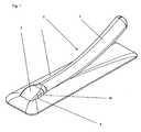
- the Fig. 1shows an isometric view of a first embodiment of the holder according to the invention with a scanner 2.
- a base body 1 of the holdertakes the scanner 2 in the region of the scanner head 3 and partly in the region of the scanner grip 4 in a receiving area 5.
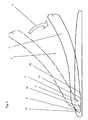
- the Fig. 2shows a schematic longitudinal section through the embodiment of Fig. 1 ,
- a dot-dash scanner border 6shows the beginning of a take place in the direction of an arrow 7 storage movement. This can be done easily and intuitively. There are no complicated locking mechanisms required which would make handling less comfortable for the user.
- the Fig. 2further shows the contour of an inner side 8 of the receiving area 5.
- Thishas two mutually substantially opposite holding portions 10, 11.
- the rear holding portion 10takes on the weight of the scanner 2 and pulls upwards laterally, such as Fig. 1 shows.
- the front holding portion 11counteracts a tilting movement.
- the scanner head 3can preferably be easily clamped. So the weight of the scanner handle 4 can be better absorbed.
- the holding areas 10, 11have a non-slip material, such as silicone, or consist thereof.
- a work area 12 of the scanner 2 with, for example, a scanner glasscomes to lie on a base area 13 of the inside 8 of the receiving area 5 and is zugeornet this.
- This base 13may according to the invention have various further advantageous technical features.
- the scanner glasswhich is usually located in the working area 13 of an intraoral scanner, can be preheated, for example, over a heated base area 13, which prevents subsequent fogging of the pane when using the scanner 2.
- a heating element 14( Fig. 5 to 8 ) be provided.
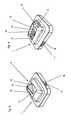
- FIG. 3 and FIG. 4show a first and a second isometric view of a second embodiment of a main body 1 of the holder.
- the receiving area 5is not recessed in the main body 1 as in the first embodiment, but rises above it.
- the receiving area 5in this preferred embodiment essentially only accommodates the scanner head 3.
- the holding areas 10, 11form in this embodiment with the boundary areas 15, 16 a border of the receiving area 5.
- a calibration element 19has a calibration pattern 21 (FIG. Fig. 5 ), which can be used for calibrations of the scanner. These may be, for example, flat-field corrections or also corrections of thermal distortions of the optics of the scanner.
- the known calibration pattern 21is recorded. Distortions of the pattern can be detected in a computer and corrected by calculation.
- Different calibration elements 19can preferably be brought into the basic body for this, since different calibration patterns 21 can be advantageous for different calibrations.
- the holdercan completely darken the working or measuring range of the scanner in order to avoid interference during calibration.
- the calibrationcan also take place without a pattern.
- the known distance between the scanner head and the calibration elementis measured and the measured and the real value compared to each other. Corresponding to the deviation then corrections or calibrations can be made.
- the calibration elementis inclined at a known angle to the working area. Thus, several known distances for calibrations are available, and the calibration can be done even more accurately.
- the angle or the position of the calibration element to the work area, or the base areafor example via a switch or lever, adjustable.
- Thismay optionally be combined with an adjusting device for the heating element; For example, it is possible first to calibrate and then to move the heating element to the working area in order to heat it.
- the patterncan also be projected by the scanner itself onto the surface of the calibration element. Then the pattern does not have to be permanently attached to the calibration element.
- the calibration elementin one development of the invention, it is alternatively or additionally also possible for the calibration element to be an object with a known, possibly more complex, uneven surface structure.
- the objectcan optionally also move, for example rotate.
- the main bodyis then designed correspondingly larger to accommodate the object and possible drives and brackets for moving the object.
- the Fig. 5shows a schematic view of the second embodiment of 3 and 4 with a scanner 2 from above. It can be seen below the working area 12 of the scanner head 3, the calibration element 19 with the calibration pattern 21.
- the heating element and the calibrationare made in one piece, for example, by a printed with a calibration heater, are also conceivable.
- feet 22Under the main body 1 you can see feet 22. These can serve as a base for the base body 1 or non-positively or cohesively, for example via suction cups or adhesive bonds, with a substrate, for example the Dental chair or a table surface to be connected.
- the Fig. 6shows a longitudinal section through the Fig. 5 , The position of the calibration element 19 and of the heating element 14 in the base body 1 can be seen.
- the working region 12 assigned to the base region 13lies above the calibration element 19. In this embodiment, a distance is provided between the calibration element 19 and the working region 12.
- Embodiments in which the work area 12 and the calibration pattern 21 are not spaced apartare also conceivable.
- the Fig. 7shows a first section along the line VII-VII in Fig. 6 ,
- the calibration element 19can also take on other tasks and for example establish a wireless data connection to the scanner and optionally read data that were previously detected by the scanner.
- a means for data transmissionoptionally also via a galvanic connection, be arranged separately in the main body.
- the Fig. 8shows a second section along the line VIII-VIII in Fig. 6 , One recognizes the heating element 14 in the recess 18 in the main body. 1
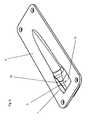
- the Fig. 9shows an isometric view of a third embodiment of the holder.
- the base body 1is not arranged on a surface, as described in the preceding embodiments of the invention, but is embedded in a surface, for example, of a table or treatment chair, and has a mounting plate 9.
- the receiving area 5is sunk in the surface.
- the Fig. 10shows a view of the third embodiment from above.
- heating or calibration elementscan also be accommodated in this embodiment be. An exchange could then be made from above before the scanner 2 is deposited.
- the Fig. 11shows a section along the line XI-XI in Fig. 10 , It can be seen how the holding area 11 opposite the holding area 10 is arranged substantially open in a V-shape to the base area 13.
- the particularly long in this embodiment, rear portion 23 of the receiving area 5can be used in a development of the invention for other functions of the holder.
- a chargercan be arranged, which is used inductively or via a galvanic connection for charging a battery in the scanner 2.
- a wireless scannercould exchange data and calibrate while it is being stored in the holder.
- the scanner headcan be preheated for a subsequent treatment and the scanner can be charged at the same time.
- a switchmay be provided on the main body. This is switched in a preferred embodiment of the invention when inserting or removing the scanner. Heating, charging, etc. are so energized only when a scanner is actually in the holder. This saves energy and prevents possible damage, for example, by overheating of the holder or the heating element before.
- a sensor for the temperature of the outside of the scannercan additionally be provided. This can display its information, for example via a display on the holder or transmit it to a computer connected to the scanner and / or the holder. In a special application of the holder and the temperature of the heating element can be controlled based on the sensor information. This can be useful, for example, if the scanner is to be used in animal dentistry, since the Temperature of the work area of the body temperature of each species can be adjusted.
Landscapes
- Health & Medical Sciences (AREA)
- Life Sciences & Earth Sciences (AREA)
- Veterinary Medicine (AREA)
- Animal Behavior & Ethology (AREA)
- General Health & Medical Sciences (AREA)
- Public Health (AREA)
- Dentistry (AREA)
- Oral & Maxillofacial Surgery (AREA)
- Epidemiology (AREA)
- Surgery (AREA)
- Nuclear Medicine, Radiotherapy & Molecular Imaging (AREA)
- Engineering & Computer Science (AREA)
- Biomedical Technology (AREA)
- Heart & Thoracic Surgery (AREA)
- Medical Informatics (AREA)
- Molecular Biology (AREA)
- Dental Tools And Instruments Or Auxiliary Dental Instruments (AREA)
- Apparatus For Radiation Diagnosis (AREA)
Description
Translated fromGermanDie Erfindung betrifft eine Halterung mit einem Grundkörper in Verbindung mit einem Handstück eines Intraoralscanners, welches einen Kopfbereich aufweist.The invention relates to a holder with a base body in conjunction with a handpiece of an intraoral scanner, which has a head portion.
Intraoralscanner finden in der Dentalmedizin zunehmend Verwendung, da sie viele Vorteile gegenüber der herkömmlichen Erfassung der Zahnstruktur von Patienten haben. Abdrücke, die für den Patienten unangenehm sind, entfallen und strahlungsbasierte Aufnahmemethoden wie das Röntgen können zum Teil vermieden werden. Nachteilig ist allerdings der häufig erhebliche Platzbedarf, da viele Systeme als integrale Geräte erhältlich sind, bei denen Computer, Bildschirm und Handstück eine Einheit bilden. Bei diesen Ausführungsformen wird der Scanner auf einem rollbaren Wagen zum Behandlungsstuhl gefahren. Andere Systeme können mit herkömmlichen Rechnern betrieben werden. In solchen Fällen erfolgt die visuelle Ausgabe der Scans über das normale Computerdisplay. Das jedenfalls notwendige Handstück kann dann beispielsweise über einen USB-Port an den Computer angeschlossen werden. Manchmal befinden sich hierfür eigene Schnittstellen am Behandlungsstuhl. Besonders fortschrittliche Systeme verfügen über die Möglichkeit einer drahtlosen Datenübertragung und können so besonders komfortabel genutzt werden. Ein Problem stellt sich bei allen Systemen dann, wenn der Scanner nicht genutzt wird. Ein großer Wagen ist generell unpraktisch und die üblichen, an einem Behandlungsstuhl angebrachten, Aufbewahrungsmöglichkeiten sind in der Regel nicht für Intraoralscanner geeignet, da diese sich in ihrer Form in der Regel von den sonst üblichen Behandlungsgeräten unterscheiden.Intraoral scanners are increasingly being used in dental medicine because they have many advantages over the conventional detection of the tooth structure of patients. Imprints that are uncomfortable for the patient are eliminated and radiation-based imaging methods such as X-rays can be partially avoided. However, the disadvantage is often the considerable space requirements, since many systems are available as integral devices in which computer, screen and handpiece form a unit. In these embodiments, the scanner is run on a rollable cart to the treatment chair. Other systems can be operated with conventional computers. In such cases, the visual output of the scans will be from the normal computer display. The necessary handpiece can then be connected to the computer via a USB port, for example. Sometimes there are separate interfaces to the treatment chair. Particularly advanced systems have the option of wireless data transmission and can therefore be used in a particularly convenient way. A problem arises with all systems when the scanner is not used. A large cart is generally impractical and the usual storage options attached to a treatment chair are generally not suitable for intraoral scanners, as these generally differ in shape from the usual treatment devices.
Aufgabe der Erfindung ist es daher, eine gegebenenfalls nachrüstbare und für den Nutzer besonders komfortable Halterung für einen Intraoralscanner zur Verfügung zu stellen.The object of the invention is therefore to provide an optionally retrofittable and particularly comfortable for the user holder for an intraoral scanner.
Gelöst wird diese Aufgabe durch eine Halterung der eingangs genannten Art, die durch einen Aufnahmebereich des Grundkörpers, in welchem der Kopfbereich wenigsten teilweise formschlüssig aufnehmbar ist und der eine Innenseite mit wenigstens zwei Haltebereichen aufweist, die einander im Wesentlichen gegenüber liegend angeordnet sind, gekennzeichnet ist.This object is achieved by a holder of the type mentioned, which is at least partially positively received by a receiving region of the base body, in which the head area and an inner side with at least two Holding areas, which are arranged substantially opposite each other, is characterized.
So kann der Intraoralscanner mit seinem Kopfbereich einfach und schnell in die Halterung gehängt bzw. gelegt werden.Thus, the intraoral scanner with its head area can be easily and quickly hung or placed in the holder.
Weitere bevorzugte und vorteilhafte Ausführungsformen der Erfindung sind Gegenstand der Unteransprüche.Further preferred and advantageous embodiments of the invention are the subject of the dependent claims.
Weitere Einzelheiten und Merkmale der Erfindung sowie Vorteile derselben ergeben sich aus der nachstehenden Beschreibung bevorzugter Ausführungsformen der Erfindung unter Bezugnahme auf die in den Zeichnungen beispielhaft dargestellten Ausführungsformen. Es zeigt:
- Fig. 1
- eine isometrische Ansicht einer ersten Ausführungsform der erfindungsgemäßen Halterung mit einem Scanner,
- Fig. 2
- eine schematisierte Seitenansicht der Ausführungsform von
Fig. 1 , - Fig. 3
- eine erste isometrische Ansicht einer zweiten Ausführungsform der Halterung,
- Fig. 4
- eine zweite isometrische Ansicht der zweiten Ausführungsform,
- Fig. 5
- eine Ansicht der zweiten Ausführungsform mit einem Scanner von oben,
- Fig. 6
- einen Längsschnitt durch die Ausführungsform von
Fig. 5 , - Fig. 7
- einen ersten Schnitt durch die Ausführungsform von
Fig. 5 und 6 , - Fig. 8
- einen zweiten Schnitt durch die Ausführungsform von
Fig. 5 und 6 , - Fig. 9
- eine isometrische Ansicht einer dritten Ausführungsform der Halterung,
- Fig. 10
- eine Ansicht der dritten Ausführungsform von oben und
- Fig. 11
- einen Schnitt durch die
Fig. 10 .
- Fig. 1
- an isometric view of a first embodiment of the holder according to the invention with a scanner,
- Fig. 2
- a schematic side view of the embodiment of
Fig. 1 . - Fig. 3
- a first isometric view of a second embodiment of the holder,
- Fig. 4
- a second isometric view of the second embodiment,
- Fig. 5
- a view of the second embodiment with a scanner from above,
- Fig. 6
- a longitudinal section through the embodiment of
Fig. 5 . - Fig. 7
- a first section through the embodiment of
FIGS. 5 and 6 . - Fig. 8
- a second section through the embodiment of
FIGS. 5 and 6 . - Fig. 9
- an isometric view of a third embodiment of the holder,
- Fig. 10
- a view of the third embodiment from above and
- Fig. 11
- a cut through the
Fig. 10 ,
Die
Die
Die
Die
Weiters erkennt man an einer Seite des Grundkörpers 1 Ausnehmungen 17, 18, die zur Seite des Grundkörpers hin offen sind. In diesen Ausnehmungen 17, 18 können beispielsweise Heizelemente 14 oder Kalibrierelemente 19 (
Gemäß einer alternativen oder zusätzlichen Ausführungsform der Erfindung kann das Kalibrieren auch ohne ein Muster erfolgen. Dabei wird der bekannte Abstand zwischen dem Scannerkopf und dem Kalibrierelement vermessen und der gemessene und der reale Wert miteinander verglichen. Entsprechend der Abweichung können dann Korrekturen bzw. Kalibrierungen vorgenommen werden. In einer Weiterbildung der Erfindung, die auch bei Kalibrierelementen mit Kalibriermuster Anwendung finden kann, ist das Kalibrierelement um einen bekannten Winkel zum Arbeitsbereich geneigt. So stehen mehrere bekannte Abstände für Kalibrierungen zur Verfügung, und das Kalibrieren kann noch genauer erfolgen. In einer weiteren Weiterbildung ist der Winkel bzw. die Position des Kalibrierelementes zum Arbeitsbereich, bzw. der Grundfläche, beispielsweise über einen Schalter oder Hebel, verstellbar. Dies kann gegebenfalls mit einer Verstelleinrichtung für das Heizelement kombiniert werden; so kann beispielsweise zunächst kalibriert werden und dann das Heizelement an den Arbeitsbereich geschoben werden, um diesen zu wärmen. Das Muster kann auch vom Scanner selbst auf die Oberfläche des Kalibrierelementes projiziert werden. Dann muss das Muster nicht dauerhaft auf dem Kalibrierelement angebracht sein.According to an alternative or additional embodiment of the invention, the calibration can also take place without a pattern. The known distance between the scanner head and the calibration element is measured and the measured and the real value compared to each other. Corresponding to the deviation then corrections or calibrations can be made. In a further development of the invention, which can also be used for calibration elements with calibration patterns, the calibration element is inclined at a known angle to the working area. Thus, several known distances for calibrations are available, and the calibration can be done even more accurately. In a further development, the angle or the position of the calibration element to the work area, or the base area, for example via a switch or lever, adjustable. This may optionally be combined with an adjusting device for the heating element; For example, it is possible first to calibrate and then to move the heating element to the working area in order to heat it. The pattern can also be projected by the scanner itself onto the surface of the calibration element. Then the pattern does not have to be permanently attached to the calibration element.
In einer Weiterbildung der Erfindung ist es alternativ oder zusätzlich auch möglich, dass das Kalibrierelement ein Objekt mit einer bekannten, gegebenenfalls komplexeren, unebenen Oberflächenstruktur ist. Das Objekt kann sich optional auch bewegen, beispielsweise drehen. Der Grundkörper gestaltet sich dann entsprechend größer um das Objekt und mögliche Antriebe und Halterungen zum Bewegen des Objektes aufzunehmen.In one development of the invention, it is alternatively or additionally also possible for the calibration element to be an object with a known, possibly more complex, uneven surface structure. The object can optionally also move, for example rotate. The main body is then designed correspondingly larger to accommodate the object and possible drives and brackets for moving the object.
Die
Die
Die
Die
Die
Die
Die
Ein drahtloser Scanner könnte so zum Beispiel während der Ablage in der Halterung Daten austauschen und sich kalibrieren. Außerdem kann der Scannerkopf für eine folgende Behandlung vorgewärmt und der Scanner gleichzeitig geladen werden. Um eine oder mehrere dieser Funktionen in Gang zu setzten, kann ein Schalter am Grundkörper vorgesehen sein. Dieser wird in einer bevorzugten Weiterbildung der Erfindung beim Einsetzen bzw. Herausnehmen des Scanners geschaltet. Heizung, Ladefunktion usw. werden also erst dann bestromt, wenn sich auch tatsächlich ein Scanner in der Halterung befindet. Dies spart Energie und beugt möglichen Beschädigungen, beispielweise durch ein Überhitzen der Halterung bzw. des Heizelementes, vor.For example, a wireless scanner could exchange data and calibrate while it is being stored in the holder. In addition, the scanner head can be preheated for a subsequent treatment and the scanner can be charged at the same time. To set one or more of these functions in motion, a switch may be provided on the main body. This is switched in a preferred embodiment of the invention when inserting or removing the scanner. Heating, charging, etc. are so energized only when a scanner is actually in the holder. This saves energy and prevents possible damage, for example, by overheating of the holder or the heating element before.
In einer Weiterbildung der Erfindung kann zusätzlich auch ein Sensor für die Temperatur der Außenseite des Scanner vorgesehen sein. Dieser kann seine Informationen beispielsweise über ein Display an der Halterung anzeigen oder auch an einen mit dem Scanner und/oder der Halterung verbunden Rechner übermitteln. In einer speziellen Anwendung der Halterung kann auch die Temperatur des Heizelementes aufgrund der Sensorinformationen geregelt werden. Dies kann beispielsweise dann sinnvoll sein, wenn der Scanner in der Tierzahnheilkunde eingesetzt werden soll, da die Temperatur des Arbeitsbereiches der Körpertemperatur der jeweiligen Tierart angepasst werden kann.In a development of the invention, a sensor for the temperature of the outside of the scanner can additionally be provided. This can display its information, for example via a display on the holder or transmit it to a computer connected to the scanner and / or the holder. In a special application of the holder and the temperature of the heating element can be controlled based on the sensor information. This can be useful, for example, if the scanner is to be used in animal dentistry, since the Temperature of the work area of the body temperature of each species can be adjusted.
Claims (23)
- Mounting having a base body in conjunction with a handpiece of an intraoral scanner, which has a head region (3),characterized by a accommodation region (5) of the base body (1), in which the head region (3) can be accommodated at in an least partially form-fitting manner, and which has an inner surface (8) having at least two holding regions (10, 11) arranged essentially opposite to one another.
- Mounting according to claim 1,characterized in that the inner surface (8) has a base region (13), which is assigned to a working region (12) of the head region (3).
- Mounting according to claim 2,characterized in that at least one holding region (11) is a U-shaped or V-shaped mounting, which is open to the accommodation region (5).
- Mounting according to any one of claims 1 to 3,characterized in that the inner surface (8) has at least one, preferably two, bordering regions (15, 16) for the accommodation region (5).
- Mounting according to claim 4,characterized in that the bordering region (15, 16) is adjacent to the base region (13).
- Mounting according to claim 4 or 5,characterized in that the bordering region (15, 16) contains at least partial holding regions (10, 11).
- Mounting according to any one of claims 1 to 6,characterized in that the base region (13) has a heatable electric or electronic heating element (14).
- Mounting according to any one of claims 1 to 7,characterized in that the base body (1) has an inductive charging device.
- Mounting according to any one of claims 1 to 7,characterized in that the base body (1) has galvanic contacts of a charging device.
- Mounting according to any one of claims 2 to 9,characterized in that the base region (13) has a calibration pattern (21).
- Mounting according to claim 10,characterized in that the heating element (14) has the calibration pattern (21).
- Mounting according to claim 10,characterized in that the heating element (14) and the calibration pattern (21) are arranged side by side.
- Mounting according to any one of claims 10 to 12,characterized in that the base body (1) has a recess (17, 18), in which a heating element (14) or a calibration element (19) can be accommodated.
- Mounting according to claim 13,characterized in that the calibration element (19) has a calibration pattern (21).
- Mounting according to claim 13 or 14,characterized in that the position(s) of the heating element (14) and/or of the calibration element (19) is/are adjustable by means of a switch or a lever.
- Mounting according to any one of claims 13 to 15,characterized in that the recess (17, 18) is open toward an exterior side of the base body (1).
- Mounting according to any one of claims 7 to 16,characterized in that the base body (1) has at least one switch with which the heating element (14) and/or the charging device can be turned on.
- Mounting according to any one of claims 1 to 17,characterized in that the base body (1) has a contact switch, whose switch position is controlled by the presence or absence of the scanner or the scanner head, respectively.
- Mounting according to claim 18,characterized in that the contact switch switches the heating element (14) and/or the charging device on or off, respectively.
- Mounting according to any one of claims 1 to 19,characterized in that the base body (1) has a means for data transmission between the base body (1) and the handpiece.
- Mounting according to any one of claims 1 to 20,characterized in that the base body (1) completely covers a measurement range of the handpiece.
- Mounting according to any one of claims 1 to 21,characterized in that the mounting has a temperature sensor.
- Mounting according to claim 22,characterized in that the mounting has a display, in particular a display screen, for a value determined by the temperature sensor.
Applications Claiming Priority (1)
| Application Number | Priority Date | Filing Date | Title |
|---|---|---|---|
| ATGM77/2013UAT13546U1 (en) | 2013-03-08 | 2013-03-08 | Holder for an intraoral scanner |
Publications (3)
| Publication Number | Publication Date |
|---|---|
| EP2774576A2 EP2774576A2 (en) | 2014-09-10 |
| EP2774576A3 EP2774576A3 (en) | 2014-12-24 |
| EP2774576B1true EP2774576B1 (en) | 2016-01-13 |
Family
ID=50238018
Family Applications (1)
| Application Number | Title | Priority Date | Filing Date |
|---|---|---|---|
| EP14450009.7AActiveEP2774576B1 (en) | 2013-03-08 | 2014-03-06 | Holder for an intra-oral scanner |
Country Status (4)
| Country | Link |
|---|---|
| US (1) | US20140255868A1 (en) |
| EP (1) | EP2774576B1 (en) |
| AT (1) | AT13546U1 (en) |
| ES (1) | ES2565509T3 (en) |
Families Citing this family (8)
| Publication number | Priority date | Publication date | Assignee | Title |
|---|---|---|---|---|
| EP3067010B1 (en) | 2015-03-07 | 2017-05-31 | a.tron3d GmbH | Holder for an intra-oral scanner |
| TWI626920B (en)* | 2016-11-09 | 2018-06-21 | 佳世達科技股份有限公司 | Defogging device |
| EP3375405A1 (en)* | 2017-03-17 | 2018-09-19 | a.tron3d GmbH | Device for operating an intraoral scanner |
| KR101941001B1 (en)* | 2017-05-17 | 2019-01-22 | 주식회사 바텍 | Calibration Cradle For Intra-Oral Scanner And Intra-Oral Scanner System Comprising The Same |
| US10835352B2 (en)* | 2018-03-19 | 2020-11-17 | 3D Imaging and Simulation Corp. Americas | Intraoral scanner and computing system for capturing images and generating three-dimensional models |
| KR102620826B1 (en)* | 2021-07-15 | 2024-01-04 | 오스템임플란트 주식회사 | System for oral scanner |
| CN119451644A (en)* | 2022-06-09 | 2025-02-14 | 3 形状股份有限公司 | Support unit for intraoral scanning device |
| KR20240165063A (en)* | 2023-05-15 | 2024-11-22 | 가톨릭대학교 산학협력단 | Cover for dental scanner |
Family Cites Families (19)
| Publication number | Priority date | Publication date | Assignee | Title |
|---|---|---|---|---|
| US3883716A (en)* | 1971-03-08 | 1975-05-13 | William S Fortune | Temperature controlled soldering instrument |
| DE3538545A1 (en)* | 1985-10-30 | 1987-05-07 | Braun Ag | WIRELESS CURRENT BAR WITH A SEPARATE HEATING STATION |
| US5880826A (en)* | 1997-07-01 | 1999-03-09 | L J Laboratories, L.L.C. | Apparatus and method for measuring optical characteristics of teeth |
| DE20007821U1 (en)* | 2000-05-04 | 2001-06-13 | Furtwängler, Bernhard, 10829 Berlin | Modeling device |
| JPWO2002065937A1 (en)* | 2001-02-21 | 2004-06-17 | デンタルシステムズ株式会社 | Light irradiation device |
| US7112812B2 (en)* | 2001-12-28 | 2006-09-26 | Applied Materials, Inc. | Optical measurement apparatus |
| US6761561B2 (en)* | 2002-06-07 | 2004-07-13 | Schick Technologies | Wireless dental camera |
| US7015423B2 (en)* | 2003-05-19 | 2006-03-21 | Joshua Friedman | Heating device for dental material |
| US20060229502A1 (en)* | 2003-06-03 | 2006-10-12 | Bayer Healthcare Llc | Portable medical diagnostic apparatus |
| US20060199146A1 (en)* | 2005-03-01 | 2006-09-07 | Schick Technologies | Method of transferring power and data via an inductive link |
| US20060294586A1 (en)* | 2005-06-28 | 2006-12-28 | Upton John D | Security locking apparatus and method for portable computer |
| US7181927B2 (en)* | 2005-07-01 | 2007-02-27 | Alsius Corporation | Primary heat exchanger for patient temperature control |
| JP5358400B2 (en)* | 2008-11-12 | 2013-12-04 | 株式会社モリタ製作所 | Dental instrument holder, dental care tray table and dental care unit |
| DE202009008270U1 (en)* | 2009-06-10 | 2010-11-04 | Kollewe, Thomas | Device for tempering a test liquid |
| EP2339382A1 (en)* | 2009-12-22 | 2011-06-29 | 3M Innovative Properties Company | A light guide for a dental light device and a method of making the light guide |
| TWM384018U (en)* | 2010-03-12 | 2010-07-11 | Winharbor Technology Co Ltd | Wireless rechargeable thermit pad |
| WO2011163541A1 (en)* | 2010-06-24 | 2011-12-29 | Avery Dennison Corporation | Hand-held portable printer |
| DE102011012419A1 (en)* | 2011-02-22 | 2012-08-23 | Karl Storz Gmbh & Co. Kg | Device for temporarily holding an object |
| US20120330555A1 (en)* | 2011-06-21 | 2012-12-27 | Gadlight, Inc. | Analyte Testing System with Docking Station for Data Management |
- 2013
- 2013-03-08ATATGM77/2013Upatent/AT13546U1/ennot_activeIP Right Cessation
- 2014
- 2014-03-06EPEP14450009.7Apatent/EP2774576B1/enactiveActive
- 2014-03-06ESES14450009.7Tpatent/ES2565509T3/enactiveActive
- 2014-03-07USUS14/200,844patent/US20140255868A1/ennot_activeAbandoned
Also Published As
| Publication number | Publication date |
|---|---|
| AT13546U1 (en) | 2014-03-15 |
| ES2565509T3 (en) | 2016-04-05 |
| EP2774576A2 (en) | 2014-09-10 |
| US20140255868A1 (en) | 2014-09-11 |
| EP2774576A3 (en) | 2014-12-24 |
Similar Documents
| Publication | Publication Date | Title |
|---|---|---|
| EP2774576B1 (en) | Holder for an intra-oral scanner | |
| USD979787S1 (en) | Diagnostic apparatus for medical or laboratory purposes | |
| USD628294S1 (en) | Scanner for X-ray tomography diagnosis apparatus with a nuclear medical diagnostic imaging apparatus | |
| DE3036217C2 (en) | Remote-controlled medical device | |
| USD914230S1 (en) | Medical apparatus | |
| DE102006038067B4 (en) | Medical device | |
| DE2844650A1 (en) | BREAD ROESTER | |
| EP1905358A2 (en) | Patient positioning device of a panoramic dental x-ray apparatus | |
| DE202009002897U1 (en) | Patient table for radiology | |
| DE202013001908U1 (en) | Ray imaging apparatus | |
| DE202005021580U1 (en) | Thermotherapy device | |
| DE102018109977A1 (en) | Medical treatment device as well as attachment | |
| DE3330813C2 (en) | Device for making nail corrections | |
| EP0413036A1 (en) | Device to heat, warm or keep warm, especially for scorching salamanders in particular | |
| EP3062687B1 (en) | Elastic sensor for measuring vital parameters in the auditory canal | |
| DE102011015974A1 (en) | Cooking device with a crucible, a lid and a cooking appliance control and method for controlling a cooking process | |
| EP3067010B1 (en) | Holder for an intra-oral scanner | |
| WO2016124650A1 (en) | Dental light curing device | |
| DE102007031920B3 (en) | Examination table with a transfer device and use of a transfer device with an examination table | |
| CN210541854U (en) | Tumor anesthesia branch of academic or vocational study is with firm mechanism of monitor | |
| DE10062127C2 (en) | Heat therapy device with sliding mattress base | |
| DE202015104506U1 (en) | Apparatus for treating tissue of a cervix | |
| AT516002B1 (en) | Method for creating a digital denture model | |
| DE202014000927U1 (en) | compression unit | |
| BE1030929B1 (en) | Method for calibrating a dirty infrared sensor, method for measuring a temperature with a dirty infrared sensor and kitchen appliance |
Legal Events
| Date | Code | Title | Description |
|---|---|---|---|
| PUAI | Public reference made under article 153(3) epc to a published international application that has entered the european phase | Free format text:ORIGINAL CODE: 0009012 | |
| 17P | Request for examination filed | Effective date:20140306 | |
| AK | Designated contracting states | Kind code of ref document:A2 Designated state(s):AL AT BE BG CH CY CZ DE DK EE ES FI FR GB GR HR HU IE IS IT LI LT LU LV MC MK MT NL NO PL PT RO RS SE SI SK SM TR | |
| AX | Request for extension of the european patent | Extension state:BA ME | |
| PUAL | Search report despatched | Free format text:ORIGINAL CODE: 0009013 | |
| AK | Designated contracting states | Kind code of ref document:A3 Designated state(s):AL AT BE BG CH CY CZ DE DK EE ES FI FR GB GR HR HU IE IS IT LI LT LU LV MC MK MT NL NO PL PT RO RS SE SI SK SM TR | |
| AX | Request for extension of the european patent | Extension state:BA ME | |
| RIC1 | Information provided on ipc code assigned before grant | Ipc:A61C 9/00 20060101AFI20141119BHEP Ipc:A61G 15/16 20060101ALI20141119BHEP | |
| R17P | Request for examination filed (corrected) | Effective date:20150323 | |
| RAX | Requested extension states of the european patent have changed | Extension state:ME Payment date:20150323 Extension state:BA Payment date:20150323 | |
| RBV | Designated contracting states (corrected) | Designated state(s):AL AT BE BG CH CY CZ DE DK EE ES FI FR GB GR HR HU IE IS IT LI LT LU LV MC MK MT NL NO PL PT RO RS SE SI SK SM TR | |
| GRAP | Despatch of communication of intention to grant a patent | Free format text:ORIGINAL CODE: EPIDOSNIGR1 | |
| INTG | Intention to grant announced | Effective date:20150608 | |
| GRAS | Grant fee paid | Free format text:ORIGINAL CODE: EPIDOSNIGR3 | |
| GRAP | Despatch of communication of intention to grant a patent | Free format text:ORIGINAL CODE: EPIDOSNIGR1 | |
| INTG | Intention to grant announced | Effective date:20151102 | |
| GRAA | (expected) grant | Free format text:ORIGINAL CODE: 0009210 | |
| AK | Designated contracting states | Kind code of ref document:B1 Designated state(s):AL AT BE BG CH CY CZ DE DK EE ES FI FR GB GR HR HU IE IS IT LI LT LU LV MC MK MT NL NO PL PT RO RS SE SI SK SM TR | |
| AX | Request for extension of the european patent | Extension state:BA ME | |
| REG | Reference to a national code | Ref country code:GB Ref legal event code:FG4D Free format text:NOT ENGLISH | |
| REG | Reference to a national code | Ref country code:CH Ref legal event code:EP | |
| REG | Reference to a national code | Ref country code:IE Ref legal event code:FG4D Free format text:LANGUAGE OF EP DOCUMENT: GERMAN | |
| REG | Reference to a national code | Ref country code:AT Ref legal event code:REF Ref document number:769982 Country of ref document:AT Kind code of ref document:T Effective date:20160215 | |
| REG | Reference to a national code | Ref country code:DE Ref legal event code:R096 Ref document number:502014000293 Country of ref document:DE | |
| REG | Reference to a national code | Ref country code:ES Ref legal event code:FG2A Ref document number:2565509 Country of ref document:ES Kind code of ref document:T3 Effective date:20160405 | |
| REG | Reference to a national code | Ref country code:LT Ref legal event code:MG4D | |
| REG | Reference to a national code | Ref country code:NL Ref legal event code:MP Effective date:20160113 | |
| REG | Reference to a national code | Ref country code:FR Ref legal event code:PLFP Year of fee payment:3 | |
| PG25 | Lapsed in a contracting state [announced via postgrant information from national office to epo] | Ref country code:NL Free format text:LAPSE BECAUSE OF FAILURE TO SUBMIT A TRANSLATION OF THE DESCRIPTION OR TO PAY THE FEE WITHIN THE PRESCRIBED TIME-LIMIT Effective date:20160113 | |
| PG25 | Lapsed in a contracting state [announced via postgrant information from national office to epo] | Ref country code:GR Free format text:LAPSE BECAUSE OF FAILURE TO SUBMIT A TRANSLATION OF THE DESCRIPTION OR TO PAY THE FEE WITHIN THE PRESCRIBED TIME-LIMIT Effective date:20160414 Ref country code:HR Free format text:LAPSE BECAUSE OF FAILURE TO SUBMIT A TRANSLATION OF THE DESCRIPTION OR TO PAY THE FEE WITHIN THE PRESCRIBED TIME-LIMIT Effective date:20160113 Ref country code:FI Free format text:LAPSE BECAUSE OF FAILURE TO SUBMIT A TRANSLATION OF THE DESCRIPTION OR TO PAY THE FEE WITHIN THE PRESCRIBED TIME-LIMIT Effective date:20160113 Ref country code:NO Free format text:LAPSE BECAUSE OF FAILURE TO SUBMIT A TRANSLATION OF THE DESCRIPTION OR TO PAY THE FEE WITHIN THE PRESCRIBED TIME-LIMIT Effective date:20160413 | |
| PG25 | Lapsed in a contracting state [announced via postgrant information from national office to epo] | Ref country code:LT Free format text:LAPSE BECAUSE OF FAILURE TO SUBMIT A TRANSLATION OF THE DESCRIPTION OR TO PAY THE FEE WITHIN THE PRESCRIBED TIME-LIMIT Effective date:20160113 Ref country code:BE Free format text:LAPSE BECAUSE OF NON-PAYMENT OF DUE FEES Effective date:20160331 Ref country code:LV Free format text:LAPSE BECAUSE OF FAILURE TO SUBMIT A TRANSLATION OF THE DESCRIPTION OR TO PAY THE FEE WITHIN THE PRESCRIBED TIME-LIMIT Effective date:20160113 Ref country code:PT Free format text:LAPSE BECAUSE OF FAILURE TO SUBMIT A TRANSLATION OF THE DESCRIPTION OR TO PAY THE FEE WITHIN THE PRESCRIBED TIME-LIMIT Effective date:20160513 Ref country code:SE Free format text:LAPSE BECAUSE OF FAILURE TO SUBMIT A TRANSLATION OF THE DESCRIPTION OR TO PAY THE FEE WITHIN THE PRESCRIBED TIME-LIMIT Effective date:20160113 Ref country code:PL Free format text:LAPSE BECAUSE OF FAILURE TO SUBMIT A TRANSLATION OF THE DESCRIPTION OR TO PAY THE FEE WITHIN THE PRESCRIBED TIME-LIMIT Effective date:20160113 Ref country code:IS Free format text:LAPSE BECAUSE OF FAILURE TO SUBMIT A TRANSLATION OF THE DESCRIPTION OR TO PAY THE FEE WITHIN THE PRESCRIBED TIME-LIMIT Effective date:20160513 Ref country code:RS Free format text:LAPSE BECAUSE OF FAILURE TO SUBMIT A TRANSLATION OF THE DESCRIPTION OR TO PAY THE FEE WITHIN THE PRESCRIBED TIME-LIMIT Effective date:20160113 | |
| REG | Reference to a national code | Ref country code:DE Ref legal event code:R097 Ref document number:502014000293 Country of ref document:DE | |
| PG25 | Lapsed in a contracting state [announced via postgrant information from national office to epo] | Ref country code:DK Free format text:LAPSE BECAUSE OF FAILURE TO SUBMIT A TRANSLATION OF THE DESCRIPTION OR TO PAY THE FEE WITHIN THE PRESCRIBED TIME-LIMIT Effective date:20160113 Ref country code:LU Free format text:LAPSE BECAUSE OF FAILURE TO SUBMIT A TRANSLATION OF THE DESCRIPTION OR TO PAY THE FEE WITHIN THE PRESCRIBED TIME-LIMIT Effective date:20160306 Ref country code:EE Free format text:LAPSE BECAUSE OF FAILURE TO SUBMIT A TRANSLATION OF THE DESCRIPTION OR TO PAY THE FEE WITHIN THE PRESCRIBED TIME-LIMIT Effective date:20160113 Ref country code:MC Free format text:LAPSE BECAUSE OF FAILURE TO SUBMIT A TRANSLATION OF THE DESCRIPTION OR TO PAY THE FEE WITHIN THE PRESCRIBED TIME-LIMIT Effective date:20160113 | |
| PLBE | No opposition filed within time limit | Free format text:ORIGINAL CODE: 0009261 | |
| STAA | Information on the status of an ep patent application or granted ep patent | Free format text:STATUS: NO OPPOSITION FILED WITHIN TIME LIMIT | |
| PG25 | Lapsed in a contracting state [announced via postgrant information from national office to epo] | Ref country code:RO Free format text:LAPSE BECAUSE OF FAILURE TO SUBMIT A TRANSLATION OF THE DESCRIPTION OR TO PAY THE FEE WITHIN THE PRESCRIBED TIME-LIMIT Effective date:20160113 Ref country code:SM Free format text:LAPSE BECAUSE OF FAILURE TO SUBMIT A TRANSLATION OF THE DESCRIPTION OR TO PAY THE FEE WITHIN THE PRESCRIBED TIME-LIMIT Effective date:20160113 Ref country code:CZ Free format text:LAPSE BECAUSE OF FAILURE TO SUBMIT A TRANSLATION OF THE DESCRIPTION OR TO PAY THE FEE WITHIN THE PRESCRIBED TIME-LIMIT Effective date:20160113 Ref country code:SK Free format text:LAPSE BECAUSE OF FAILURE TO SUBMIT A TRANSLATION OF THE DESCRIPTION OR TO PAY THE FEE WITHIN THE PRESCRIBED TIME-LIMIT Effective date:20160113 | |
| 26N | No opposition filed | Effective date:20161014 | |
| REG | Reference to a national code | Ref country code:IE Ref legal event code:MM4A | |
| PG25 | Lapsed in a contracting state [announced via postgrant information from national office to epo] | Ref country code:IE Free format text:LAPSE BECAUSE OF NON-PAYMENT OF DUE FEES Effective date:20160306 | |
| PG25 | Lapsed in a contracting state [announced via postgrant information from national office to epo] | Ref country code:SI Free format text:LAPSE BECAUSE OF FAILURE TO SUBMIT A TRANSLATION OF THE DESCRIPTION OR TO PAY THE FEE WITHIN THE PRESCRIBED TIME-LIMIT Effective date:20160113 Ref country code:BG Free format text:LAPSE BECAUSE OF FAILURE TO SUBMIT A TRANSLATION OF THE DESCRIPTION OR TO PAY THE FEE WITHIN THE PRESCRIBED TIME-LIMIT Effective date:20160413 | |
| REG | Reference to a national code | Ref country code:FR Ref legal event code:PLFP Year of fee payment:4 | |
| PGFP | Annual fee paid to national office [announced via postgrant information from national office to epo] | Ref country code:ES Payment date:20170202 Year of fee payment:4 | |
| PG25 | Lapsed in a contracting state [announced via postgrant information from national office to epo] | Ref country code:MT Free format text:LAPSE BECAUSE OF FAILURE TO SUBMIT A TRANSLATION OF THE DESCRIPTION OR TO PAY THE FEE WITHIN THE PRESCRIBED TIME-LIMIT Effective date:20160113 | |
| REG | Reference to a national code | Ref country code:CH Ref legal event code:PL | |
| PG25 | Lapsed in a contracting state [announced via postgrant information from national office to epo] | Ref country code:LI Free format text:LAPSE BECAUSE OF NON-PAYMENT OF DUE FEES Effective date:20170331 Ref country code:CH Free format text:LAPSE BECAUSE OF NON-PAYMENT OF DUE FEES Effective date:20170331 | |
| REG | Reference to a national code | Ref country code:FR Ref legal event code:PLFP Year of fee payment:5 | |
| PG25 | Lapsed in a contracting state [announced via postgrant information from national office to epo] | Ref country code:HU Free format text:LAPSE BECAUSE OF FAILURE TO SUBMIT A TRANSLATION OF THE DESCRIPTION OR TO PAY THE FEE WITHIN THE PRESCRIBED TIME-LIMIT; INVALID AB INITIO Effective date:20140306 | |
| PG25 | Lapsed in a contracting state [announced via postgrant information from national office to epo] | Ref country code:MK Free format text:LAPSE BECAUSE OF FAILURE TO SUBMIT A TRANSLATION OF THE DESCRIPTION OR TO PAY THE FEE WITHIN THE PRESCRIBED TIME-LIMIT Effective date:20160113 Ref country code:TR Free format text:LAPSE BECAUSE OF FAILURE TO SUBMIT A TRANSLATION OF THE DESCRIPTION OR TO PAY THE FEE WITHIN THE PRESCRIBED TIME-LIMIT Effective date:20160113 Ref country code:CY Free format text:LAPSE BECAUSE OF FAILURE TO SUBMIT A TRANSLATION OF THE DESCRIPTION OR TO PAY THE FEE WITHIN THE PRESCRIBED TIME-LIMIT Effective date:20160113 | |
| PG25 | Lapsed in a contracting state [announced via postgrant information from national office to epo] | Ref country code:AL Free format text:LAPSE BECAUSE OF FAILURE TO SUBMIT A TRANSLATION OF THE DESCRIPTION OR TO PAY THE FEE WITHIN THE PRESCRIBED TIME-LIMIT Effective date:20160113 | |
| PGFP | Annual fee paid to national office [announced via postgrant information from national office to epo] | Ref country code:GB Payment date:20190306 Year of fee payment:6 Ref country code:IT Payment date:20190301 Year of fee payment:6 | |
| PGFP | Annual fee paid to national office [announced via postgrant information from national office to epo] | Ref country code:AT Payment date:20190327 Year of fee payment:6 | |
| REG | Reference to a national code | Ref country code:ES Ref legal event code:FD2A Effective date:20190830 | |
| PG25 | Lapsed in a contracting state [announced via postgrant information from national office to epo] | Ref country code:ES Free format text:LAPSE BECAUSE OF NON-PAYMENT OF DUE FEES Effective date:20180307 | |
| REG | Reference to a national code | Ref country code:AT Ref legal event code:MM01 Ref document number:769982 Country of ref document:AT Kind code of ref document:T Effective date:20200306 | |
| PG25 | Lapsed in a contracting state [announced via postgrant information from national office to epo] | Ref country code:AT Free format text:LAPSE BECAUSE OF NON-PAYMENT OF DUE FEES Effective date:20200306 Ref country code:FR Free format text:LAPSE BECAUSE OF NON-PAYMENT OF DUE FEES Effective date:20200331 | |
| PGRI | Patent reinstated in contracting state [announced from national office to epo] | Ref country code:FR Effective date:20201218 | |
| GBPC | Gb: european patent ceased through non-payment of renewal fee | Effective date:20200306 | |
| PG25 | Lapsed in a contracting state [announced via postgrant information from national office to epo] | Ref country code:GB Free format text:LAPSE BECAUSE OF NON-PAYMENT OF DUE FEES Effective date:20200306 | |
| PG25 | Lapsed in a contracting state [announced via postgrant information from national office to epo] | Ref country code:IT Free format text:LAPSE BECAUSE OF NON-PAYMENT OF DUE FEES Effective date:20200306 | |
| PGFP | Annual fee paid to national office [announced via postgrant information from national office to epo] | Ref country code:FR Payment date:20220322 Year of fee payment:9 | |
| PGFP | Annual fee paid to national office [announced via postgrant information from national office to epo] | Ref country code:DE Payment date:20220525 Year of fee payment:9 | |
| REG | Reference to a national code | Ref country code:DE Ref legal event code:R119 Ref document number:502014000293 Country of ref document:DE | |
| PG25 | Lapsed in a contracting state [announced via postgrant information from national office to epo] | Ref country code:FR Free format text:LAPSE BECAUSE OF NON-PAYMENT OF DUE FEES Effective date:20230331 Ref country code:DE Free format text:LAPSE BECAUSE OF NON-PAYMENT OF DUE FEES Effective date:20231003 |