EP2774294B1 - Search space determination - Google Patents
Search space determinationDownload PDFInfo
- Publication number
- EP2774294B1 EP2774294B1EP12844776.0AEP12844776AEP2774294B1EP 2774294 B1EP2774294 B1EP 2774294B1EP 12844776 AEP12844776 AEP 12844776AEP 2774294 B1EP2774294 B1EP 2774294B1
- Authority
- EP
- European Patent Office
- Prior art keywords
- pdcch
- vrb
- vrbs
- search space
- dci
- Prior art date
- Legal status (The legal status is an assumption and is not a legal conclusion. Google has not performed a legal analysis and makes no representation as to the accuracy of the status listed.)
- Not-in-force
Links
- 238000004220aggregationMethods0.000claimsdescription90
- 230000002776aggregationEffects0.000claimsdescription90
- 230000005540biological transmissionEffects0.000claimsdescription29
- 238000004891communicationMethods0.000claimsdescription25
- 238000000034methodMethods0.000claimsdescription14
- 101150071746Pbsn geneProteins0.000claims1
- 238000013461designMethods0.000description16
- 238000003860storageMethods0.000description10
- 238000010586diagramMethods0.000description8
- 238000009826distributionMethods0.000description5
- 230000008901benefitEffects0.000description3
- 230000007774longtermEffects0.000description3
- 230000002093peripheral effectEffects0.000description3
- 230000006978adaptationEffects0.000description2
- 230000001419dependent effectEffects0.000description2
- 230000003993interactionEffects0.000description2
- 238000004519manufacturing processMethods0.000description2
- 238000013507mappingMethods0.000description2
- 230000011664signalingEffects0.000description2
- 238000013459approachMethods0.000description1
- 230000007613environmental effectEffects0.000description1
- VJYFKVYYMZPMAB-UHFFFAOYSA-NethoprophosChemical compoundCCCSP(=O)(OCC)SCCCVJYFKVYYMZPMAB-UHFFFAOYSA-N0.000description1
- 230000001788irregularEffects0.000description1
- 239000004973liquid crystal related substanceSubstances0.000description1
- 239000000463materialSubstances0.000description1
- 238000005457optimizationMethods0.000description1
- 230000002085persistent effectEffects0.000description1
- 239000000126substanceSubstances0.000description1
- 230000002123temporal effectEffects0.000description1
Images


Classifications
- H—ELECTRICITY
- H04—ELECTRIC COMMUNICATION TECHNIQUE
- H04L—TRANSMISSION OF DIGITAL INFORMATION, e.g. TELEGRAPHIC COMMUNICATION
- H04L1/00—Arrangements for detecting or preventing errors in the information received
- H04L1/12—Arrangements for detecting or preventing errors in the information received by using return channel
- H04L1/16—Arrangements for detecting or preventing errors in the information received by using return channel in which the return channel carries supervisory signals, e.g. repetition request signals
- H04L1/18—Automatic repetition systems, e.g. Van Duuren systems
- H—ELECTRICITY
- H04—ELECTRIC COMMUNICATION TECHNIQUE
- H04B—TRANSMISSION
- H04B7/00—Radio transmission systems, i.e. using radiation field
- H04B7/02—Diversity systems; Multi-antenna system, i.e. transmission or reception using multiple antennas
- H04B7/022—Site diversity; Macro-diversity
- H04B7/024—Co-operative use of antennas of several sites, e.g. in co-ordinated multipoint or co-operative multiple-input multiple-output [MIMO] systems
- H—ELECTRICITY
- H04—ELECTRIC COMMUNICATION TECHNIQUE
- H04L—TRANSMISSION OF DIGITAL INFORMATION, e.g. TELEGRAPHIC COMMUNICATION
- H04L5/00—Arrangements affording multiple use of the transmission path
- H04L5/14—Two-way operation using the same type of signal, i.e. duplex
- H—ELECTRICITY
- H04—ELECTRIC COMMUNICATION TECHNIQUE
- H04B—TRANSMISSION
- H04B7/00—Radio transmission systems, i.e. using radiation field
- H04B7/02—Diversity systems; Multi-antenna system, i.e. transmission or reception using multiple antennas
- H04B7/04—Diversity systems; Multi-antenna system, i.e. transmission or reception using multiple antennas using two or more spaced independent antennas
- H04B7/0404—Diversity systems; Multi-antenna system, i.e. transmission or reception using multiple antennas using two or more spaced independent antennas the mobile station comprising multiple antennas, e.g. to provide uplink diversity
- H—ELECTRICITY
- H04—ELECTRIC COMMUNICATION TECHNIQUE
- H04B—TRANSMISSION
- H04B7/00—Radio transmission systems, i.e. using radiation field
- H04B7/02—Diversity systems; Multi-antenna system, i.e. transmission or reception using multiple antennas
- H04B7/04—Diversity systems; Multi-antenna system, i.e. transmission or reception using multiple antennas using two or more spaced independent antennas
- H04B7/0413—MIMO systems
- H04B7/0456—Selection of precoding matrices or codebooks, e.g. using matrices antenna weighting
- H—ELECTRICITY
- H04—ELECTRIC COMMUNICATION TECHNIQUE
- H04B—TRANSMISSION
- H04B7/00—Radio transmission systems, i.e. using radiation field
- H04B7/02—Diversity systems; Multi-antenna system, i.e. transmission or reception using multiple antennas
- H04B7/04—Diversity systems; Multi-antenna system, i.e. transmission or reception using multiple antennas using two or more spaced independent antennas
- H04B7/06—Diversity systems; Multi-antenna system, i.e. transmission or reception using multiple antennas using two or more spaced independent antennas at the transmitting station
- H04B7/0613—Diversity systems; Multi-antenna system, i.e. transmission or reception using multiple antennas using two or more spaced independent antennas at the transmitting station using simultaneous transmission
- H04B7/0615—Diversity systems; Multi-antenna system, i.e. transmission or reception using multiple antennas using two or more spaced independent antennas at the transmitting station using simultaneous transmission of weighted versions of same signal
- H04B7/0619—Diversity systems; Multi-antenna system, i.e. transmission or reception using multiple antennas using two or more spaced independent antennas at the transmitting station using simultaneous transmission of weighted versions of same signal using feedback from receiving side
- H04B7/0621—Feedback content
- H04B7/0626—Channel coefficients, e.g. channel state information [CSI]
- H—ELECTRICITY
- H04—ELECTRIC COMMUNICATION TECHNIQUE
- H04J—MULTIPLEX COMMUNICATION
- H04J11/00—Orthogonal multiplex systems, e.g. using WALSH codes
- H—ELECTRICITY
- H04—ELECTRIC COMMUNICATION TECHNIQUE
- H04L—TRANSMISSION OF DIGITAL INFORMATION, e.g. TELEGRAPHIC COMMUNICATION
- H04L1/00—Arrangements for detecting or preventing errors in the information received
- H04L1/004—Arrangements for detecting or preventing errors in the information received by using forward error control
- H04L1/0056—Systems characterized by the type of code used
- H04L1/007—Unequal error protection
- H—ELECTRICITY
- H04—ELECTRIC COMMUNICATION TECHNIQUE
- H04L—TRANSMISSION OF DIGITAL INFORMATION, e.g. TELEGRAPHIC COMMUNICATION
- H04L1/00—Arrangements for detecting or preventing errors in the information received
- H04L1/004—Arrangements for detecting or preventing errors in the information received by using forward error control
- H04L1/0076—Distributed coding, e.g. network coding, involving channel coding
- H04L1/0077—Cooperative coding
- H—ELECTRICITY
- H04—ELECTRIC COMMUNICATION TECHNIQUE
- H04L—TRANSMISSION OF DIGITAL INFORMATION, e.g. TELEGRAPHIC COMMUNICATION
- H04L1/00—Arrangements for detecting or preventing errors in the information received
- H04L1/12—Arrangements for detecting or preventing errors in the information received by using return channel
- H04L1/16—Arrangements for detecting or preventing errors in the information received by using return channel in which the return channel carries supervisory signals, e.g. repetition request signals
- H04L1/18—Automatic repetition systems, e.g. Van Duuren systems
- H04L1/1812—Hybrid protocols; Hybrid automatic repeat request [HARQ]
- H—ELECTRICITY
- H04—ELECTRIC COMMUNICATION TECHNIQUE
- H04L—TRANSMISSION OF DIGITAL INFORMATION, e.g. TELEGRAPHIC COMMUNICATION
- H04L1/00—Arrangements for detecting or preventing errors in the information received
- H04L1/12—Arrangements for detecting or preventing errors in the information received by using return channel
- H04L1/16—Arrangements for detecting or preventing errors in the information received by using return channel in which the return channel carries supervisory signals, e.g. repetition request signals
- H04L1/18—Automatic repetition systems, e.g. Van Duuren systems
- H04L1/1829—Arrangements specially adapted for the receiver end
- H04L1/1854—Scheduling and prioritising arrangements
- H—ELECTRICITY
- H04—ELECTRIC COMMUNICATION TECHNIQUE
- H04L—TRANSMISSION OF DIGITAL INFORMATION, e.g. TELEGRAPHIC COMMUNICATION
- H04L1/00—Arrangements for detecting or preventing errors in the information received
- H04L1/12—Arrangements for detecting or preventing errors in the information received by using return channel
- H04L1/16—Arrangements for detecting or preventing errors in the information received by using return channel in which the return channel carries supervisory signals, e.g. repetition request signals
- H04L1/18—Automatic repetition systems, e.g. Van Duuren systems
- H04L1/1829—Arrangements specially adapted for the receiver end
- H04L1/1861—Physical mapping arrangements
- H—ELECTRICITY
- H04—ELECTRIC COMMUNICATION TECHNIQUE
- H04L—TRANSMISSION OF DIGITAL INFORMATION, e.g. TELEGRAPHIC COMMUNICATION
- H04L27/00—Modulated-carrier systems
- H04L27/26—Systems using multi-frequency codes
- H—ELECTRICITY
- H04—ELECTRIC COMMUNICATION TECHNIQUE
- H04L—TRANSMISSION OF DIGITAL INFORMATION, e.g. TELEGRAPHIC COMMUNICATION
- H04L27/00—Modulated-carrier systems
- H04L27/26—Systems using multi-frequency codes
- H04L27/2601—Multicarrier modulation systems
- H04L27/2647—Arrangements specific to the receiver only
- H04L27/2655—Synchronisation arrangements
- H04L27/2662—Symbol synchronisation
- H—ELECTRICITY
- H04—ELECTRIC COMMUNICATION TECHNIQUE
- H04L—TRANSMISSION OF DIGITAL INFORMATION, e.g. TELEGRAPHIC COMMUNICATION
- H04L27/00—Modulated-carrier systems
- H04L27/26—Systems using multi-frequency codes
- H04L27/2601—Multicarrier modulation systems
- H04L27/2647—Arrangements specific to the receiver only
- H04L27/2655—Synchronisation arrangements
- H04L27/2668—Details of algorithms
- H04L27/2673—Details of algorithms characterised by synchronisation parameters
- H04L27/2675—Pilot or known symbols
- H—ELECTRICITY
- H04—ELECTRIC COMMUNICATION TECHNIQUE
- H04L—TRANSMISSION OF DIGITAL INFORMATION, e.g. TELEGRAPHIC COMMUNICATION
- H04L5/00—Arrangements affording multiple use of the transmission path
- H04L5/003—Arrangements for allocating sub-channels of the transmission path
- H04L5/0032—Distributed allocation, i.e. involving a plurality of allocating devices, each making partial allocation
- H04L5/0035—Resource allocation in a cooperative multipoint environment
- H—ELECTRICITY
- H04—ELECTRIC COMMUNICATION TECHNIQUE
- H04L—TRANSMISSION OF DIGITAL INFORMATION, e.g. TELEGRAPHIC COMMUNICATION
- H04L5/00—Arrangements affording multiple use of the transmission path
- H04L5/003—Arrangements for allocating sub-channels of the transmission path
- H04L5/0053—Allocation of signalling, i.e. of overhead other than pilot signals
- H04L5/0055—Physical resource allocation for ACK/NACK
- H—ELECTRICITY
- H04—ELECTRIC COMMUNICATION TECHNIQUE
- H04L—TRANSMISSION OF DIGITAL INFORMATION, e.g. TELEGRAPHIC COMMUNICATION
- H04L5/00—Arrangements affording multiple use of the transmission path
- H04L5/003—Arrangements for allocating sub-channels of the transmission path
- H04L5/0078—Timing of allocation
- H—ELECTRICITY
- H04—ELECTRIC COMMUNICATION TECHNIQUE
- H04L—TRANSMISSION OF DIGITAL INFORMATION, e.g. TELEGRAPHIC COMMUNICATION
- H04L5/00—Arrangements affording multiple use of the transmission path
- H04L5/22—Arrangements affording multiple use of the transmission path using time-division multiplexing
- H—ELECTRICITY
- H04—ELECTRIC COMMUNICATION TECHNIQUE
- H04W—WIRELESS COMMUNICATION NETWORKS
- H04W16/00—Network planning, e.g. coverage or traffic planning tools; Network deployment, e.g. resource partitioning or cells structures
- H04W16/24—Cell structures
- H04W16/28—Cell structures using beam steering
- H—ELECTRICITY
- H04—ELECTRIC COMMUNICATION TECHNIQUE
- H04W—WIRELESS COMMUNICATION NETWORKS
- H04W24/00—Supervisory, monitoring or testing arrangements
- H04W24/02—Arrangements for optimising operational condition
- H—ELECTRICITY
- H04—ELECTRIC COMMUNICATION TECHNIQUE
- H04W—WIRELESS COMMUNICATION NETWORKS
- H04W24/00—Supervisory, monitoring or testing arrangements
- H04W24/08—Testing, supervising or monitoring using real traffic
- H—ELECTRICITY
- H04—ELECTRIC COMMUNICATION TECHNIQUE
- H04W—WIRELESS COMMUNICATION NETWORKS
- H04W28/00—Network traffic management; Network resource management
- H04W28/02—Traffic management, e.g. flow control or congestion control
- H04W28/04—Error control
- H—ELECTRICITY
- H04—ELECTRIC COMMUNICATION TECHNIQUE
- H04W—WIRELESS COMMUNICATION NETWORKS
- H04W4/00—Services specially adapted for wireless communication networks; Facilities therefor
- H04W4/06—Selective distribution of broadcast services, e.g. multimedia broadcast multicast service [MBMS]; Services to user groups; One-way selective calling services
- H—ELECTRICITY
- H04—ELECTRIC COMMUNICATION TECHNIQUE
- H04W—WIRELESS COMMUNICATION NETWORKS
- H04W4/00—Services specially adapted for wireless communication networks; Facilities therefor
- H04W4/70—Services for machine-to-machine communication [M2M] or machine type communication [MTC]
- H—ELECTRICITY
- H04—ELECTRIC COMMUNICATION TECHNIQUE
- H04W—WIRELESS COMMUNICATION NETWORKS
- H04W52/00—Power management, e.g. Transmission Power Control [TPC] or power classes
- H04W52/02—Power saving arrangements
- H04W52/0203—Power saving arrangements in the radio access network or backbone network of wireless communication networks
- H04W52/0206—Power saving arrangements in the radio access network or backbone network of wireless communication networks in access points, e.g. base stations
- H—ELECTRICITY
- H04—ELECTRIC COMMUNICATION TECHNIQUE
- H04W—WIRELESS COMMUNICATION NETWORKS
- H04W52/00—Power management, e.g. Transmission Power Control [TPC] or power classes
- H04W52/04—Transmission power control [TPC]
- H04W52/06—TPC algorithms
- H04W52/14—Separate analysis of uplink or downlink
- H04W52/146—Uplink power control
- H—ELECTRICITY
- H04—ELECTRIC COMMUNICATION TECHNIQUE
- H04W—WIRELESS COMMUNICATION NETWORKS
- H04W52/00—Power management, e.g. Transmission Power Control [TPC] or power classes
- H04W52/04—Transmission power control [TPC]
- H04W52/18—TPC being performed according to specific parameters
- H04W52/24—TPC being performed according to specific parameters using SIR [Signal to Interference Ratio] or other wireless path parameters
- H04W52/242—TPC being performed according to specific parameters using SIR [Signal to Interference Ratio] or other wireless path parameters taking into account path loss
- H—ELECTRICITY
- H04—ELECTRIC COMMUNICATION TECHNIQUE
- H04W—WIRELESS COMMUNICATION NETWORKS
- H04W56/00—Synchronisation arrangements
- H04W56/001—Synchronization between nodes
- H04W56/0015—Synchronization between nodes one node acting as a reference for the others
- H—ELECTRICITY
- H04—ELECTRIC COMMUNICATION TECHNIQUE
- H04W—WIRELESS COMMUNICATION NETWORKS
- H04W68/00—User notification, e.g. alerting and paging, for incoming communication, change of service or the like
- H04W68/02—Arrangements for increasing efficiency of notification or paging channel
- H—ELECTRICITY
- H04—ELECTRIC COMMUNICATION TECHNIQUE
- H04W—WIRELESS COMMUNICATION NETWORKS
- H04W72/00—Local resource management
- H04W72/04—Wireless resource allocation
- H04W72/044—Wireless resource allocation based on the type of the allocated resource
- H04W72/0446—Resources in time domain, e.g. slots or frames
- H—ELECTRICITY
- H04—ELECTRIC COMMUNICATION TECHNIQUE
- H04W—WIRELESS COMMUNICATION NETWORKS
- H04W72/00—Local resource management
- H04W72/20—Control channels or signalling for resource management
- H04W72/21—Control channels or signalling for resource management in the uplink direction of a wireless link, i.e. towards the network
- H—ELECTRICITY
- H04—ELECTRIC COMMUNICATION TECHNIQUE
- H04W—WIRELESS COMMUNICATION NETWORKS
- H04W72/00—Local resource management
- H04W72/20—Control channels or signalling for resource management
- H04W72/23—Control channels or signalling for resource management in the downlink direction of a wireless link, i.e. towards a terminal
- H—ELECTRICITY
- H04—ELECTRIC COMMUNICATION TECHNIQUE
- H04W—WIRELESS COMMUNICATION NETWORKS
- H04W72/00—Local resource management
- H04W72/50—Allocation or scheduling criteria for wireless resources
- H04W72/54—Allocation or scheduling criteria for wireless resources based on quality criteria
- H04W72/542—Allocation or scheduling criteria for wireless resources based on quality criteria using measured or perceived quality
- H—ELECTRICITY
- H04—ELECTRIC COMMUNICATION TECHNIQUE
- H04W—WIRELESS COMMUNICATION NETWORKS
- H04W76/00—Connection management
- H04W76/10—Connection setup
- H04W76/11—Allocation or use of connection identifiers
- H—ELECTRICITY
- H04—ELECTRIC COMMUNICATION TECHNIQUE
- H04W—WIRELESS COMMUNICATION NETWORKS
- H04W76/00—Connection management
- H04W76/40—Connection management for selective distribution or broadcast
- H—ELECTRICITY
- H04—ELECTRIC COMMUNICATION TECHNIQUE
- H04J—MULTIPLEX COMMUNICATION
- H04J3/00—Time-division multiplex systems
- H04J3/02—Details
- H04J3/12—Arrangements providing for calling or supervisory signals
- H—ELECTRICITY
- H04—ELECTRIC COMMUNICATION TECHNIQUE
- H04L—TRANSMISSION OF DIGITAL INFORMATION, e.g. TELEGRAPHIC COMMUNICATION
- H04L1/00—Arrangements for detecting or preventing errors in the information received
- H04L1/0001—Systems modifying transmission characteristics according to link quality, e.g. power backoff
- H04L1/0023—Systems modifying transmission characteristics according to link quality, e.g. power backoff characterised by the signalling
- H04L1/0026—Transmission of channel quality indication
- H—ELECTRICITY
- H04—ELECTRIC COMMUNICATION TECHNIQUE
- H04L—TRANSMISSION OF DIGITAL INFORMATION, e.g. TELEGRAPHIC COMMUNICATION
- H04L27/00—Modulated-carrier systems
- H04L27/26—Systems using multi-frequency codes
- H04L27/2601—Multicarrier modulation systems
- H04L27/2626—Arrangements specific to the transmitter only
- H04L27/2646—Arrangements specific to the transmitter only using feedback from receiver for adjusting OFDM transmission parameters, e.g. transmission timing or guard interval length
- H—ELECTRICITY
- H04—ELECTRIC COMMUNICATION TECHNIQUE
- H04W—WIRELESS COMMUNICATION NETWORKS
- H04W52/00—Power management, e.g. Transmission Power Control [TPC] or power classes
- H04W52/04—Transmission power control [TPC]
- H04W52/18—TPC being performed according to specific parameters
- H04W52/24—TPC being performed according to specific parameters using SIR [Signal to Interference Ratio] or other wireless path parameters
- H04W52/243—TPC being performed according to specific parameters using SIR [Signal to Interference Ratio] or other wireless path parameters taking into account interferences
- H04W52/244—Interferences in heterogeneous networks, e.g. among macro and femto or pico cells or other sector / system interference [OSI]
- H—ELECTRICITY
- H04—ELECTRIC COMMUNICATION TECHNIQUE
- H04W—WIRELESS COMMUNICATION NETWORKS
- H04W52/00—Power management, e.g. Transmission Power Control [TPC] or power classes
- H04W52/04—Transmission power control [TPC]
- H04W52/30—Transmission power control [TPC] using constraints in the total amount of available transmission power
- H04W52/34—TPC management, i.e. sharing limited amount of power among users or channels or data types, e.g. cell loading
- H—ELECTRICITY
- H04—ELECTRIC COMMUNICATION TECHNIQUE
- H04W—WIRELESS COMMUNICATION NETWORKS
- H04W72/00—Local resource management
- H04W72/02—Selection of wireless resources by user or terminal
- H—ELECTRICITY
- H04—ELECTRIC COMMUNICATION TECHNIQUE
- H04W—WIRELESS COMMUNICATION NETWORKS
- H04W72/00—Local resource management
- H04W72/12—Wireless traffic scheduling
- H—ELECTRICITY
- H04—ELECTRIC COMMUNICATION TECHNIQUE
- H04W—WIRELESS COMMUNICATION NETWORKS
- H04W84/00—Network topologies
- H04W84/02—Hierarchically pre-organised networks, e.g. paging networks, cellular networks, WLAN [Wireless Local Area Network] or WLL [Wireless Local Loop]
- H04W84/10—Small scale networks; Flat hierarchical networks
- H04W84/14—WLL [Wireless Local Loop]; RLL [Radio Local Loop]
- H—ELECTRICITY
- H04—ELECTRIC COMMUNICATION TECHNIQUE
- H04W—WIRELESS COMMUNICATION NETWORKS
- H04W88/00—Devices specially adapted for wireless communication networks, e.g. terminals, base stations or access point devices
- H04W88/02—Terminal devices
- H—ELECTRICITY
- H04—ELECTRIC COMMUNICATION TECHNIQUE
- H04W—WIRELESS COMMUNICATION NETWORKS
- H04W88/00—Devices specially adapted for wireless communication networks, e.g. terminals, base stations or access point devices
- H04W88/08—Access point devices
- Y—GENERAL TAGGING OF NEW TECHNOLOGICAL DEVELOPMENTS; GENERAL TAGGING OF CROSS-SECTIONAL TECHNOLOGIES SPANNING OVER SEVERAL SECTIONS OF THE IPC; TECHNICAL SUBJECTS COVERED BY FORMER USPC CROSS-REFERENCE ART COLLECTIONS [XRACs] AND DIGESTS
- Y02—TECHNOLOGIES OR APPLICATIONS FOR MITIGATION OR ADAPTATION AGAINST CLIMATE CHANGE
- Y02D—CLIMATE CHANGE MITIGATION TECHNOLOGIES IN INFORMATION AND COMMUNICATION TECHNOLOGIES [ICT], I.E. INFORMATION AND COMMUNICATION TECHNOLOGIES AIMING AT THE REDUCTION OF THEIR OWN ENERGY USE
- Y02D30/00—Reducing energy consumption in communication networks
- Y02D30/70—Reducing energy consumption in communication networks in wireless communication networks
Definitions
- Embodiments of the present inventionrelate generally to the field of communications, and more particularly, to search space determination in wireless communication, networks.
- 3rd Generation Partnership Project's (3GPP) long term evolution-advanced (LTE-A) wireless communication standardmay be modified to add support for multi-user multiple-input multiple-output (MU-MIMO) systems.
- base stationsmay be able to schedule more mobile devices, e.g., user equipment (UE), into each LTE-A subframe during MU-MIMO operations.
- Scheduling more UEsmay decrease physical downlink control channel (PDCCH) resources available for downlink scheduling.
- PDCCHphysical downlink control channel
- Releases 8, 9, and 10 of PDCCH design in LTE-Amay limit the maximum PDCCH size to 3 orthogonal frequency domain multiplexing (OFDM) symbols.
- OFDMorthogonal frequency domain multiplexing
- an OFDM symbol limit of 3in combination with enablement of MU-MIMO operation, may limit the frequency and scheduling gains that may be available through MU-MIMO operation.
- NEC GROUP" DL control channel enhancements for Rel-11", 3GPP DRAFT; R1-112135, 3RD GENERATION PARTNERSHIP PROJECT (3GPP), MOBILE COMPETENCE CENTRE ; 650, ROUTE DES LUCIOLES ; F-06921 SOPHIA-ANTIPOLIS CEDEX ; FRANCE, (20110816), vol. RAN WG1, no. Athens, Greece relates to design considerations for E-PDCCH .
- Illustrative embodiments of the present disclosureinclude, but arc not limited to, methods, systems, and apparatuses for search space determination in a wireless communication network.
- the phrase "in one embodiment”is used repeatedly. The phrase generally does not refer to the same embodiment; however, it may.
- the terms "comprising,” “having,” and “including”are synonymous, unless the context dictates otherwise.
- the phrase “A/B”means “A or B”.
- the phrase “A and/or B”means “(A), (B), or (A and B)”.
- the phrase “at least one of A, B and C”means "(A), (B), (C),.(A and B), (A and C), (B and C) Or (A, B and C)".
- the phrase “(A) B”means "(B) or (A B)", that is, A is optional.
- modulemay refer to, be part of, or include an Application Specific Integrated Circuit (ASIC), an electronic circuit, a processor (shared, dedicated, or group) and/or memory (shared, dedicated, or group) that execute one or more software or firmware programs, a combinational logic circuit, and/or other suitable components that provide the described functionality.
- ASICApplication Specific Integrated Circuit
- processorshared, dedicated, or group
- memoryshared, dedicated, or group
- FIG. 1schematically illustrates a wireless communication network 100 in accordance with various embodiments.
- Wireless communication network 100may be an access network of a 3rd Generation Partnership Project (3GPP) long-term evolution (LTE) network such as evolved universal mobile telecommunication system (UMTS) terrestrial radio access network (E-UTRAN).
- the network 100may include a base station, e.g., enhanced node base station (eNB) 104, configured to wirelessly communicate with a mobile device or terminal, e.g., user equipment (UE) 108. While embodiments of the present invention arc described with reference to an LTE network, some embodiments may be used with other types of wireless access networks.
- 3GPP3rd Generation Partnership Project
- LTElong-term evolution
- UMTSevolved universal mobile telecommunication system
- E-UTRANterrestrial radio access network
- the network 100may include a base station, e.g., enhanced node base station (eNB) 104, configured to wirelessly communicate with a mobile device or terminal, e.g
- eNB 104may be configured to overcome the gain limitations associated with using PDCCH to schedule communications with UE 108, e.g., with MU-MIMO operations.
- eNB 104may be configured to increase the number of UEs 108 that may be scheduled during LTE wireless communications by expanding downlink control information (DCI) transmissions into physical downlink shared channel (PDSCH) space, which historically may not have been used for such purpose.
- DCIdownlink control information
- PDSCHphysical downlink shared channel
- eNB 104may be configured to determine, define, and/or allocate search space candidates (i.e., potential bearers of DCI) by defining a control space in PDSCH space. This new control space may be included within an enhanced-physical downlink control channel (E-PDCCH), at least because E-PDCCH operation may expand and enhance the capability of PDCCH operation.
- E-PDCCHenhanced-physical downlink control channel
- E-PDCCHmay be associated with PDSCH such that E-PDCCH operations consume a portion of PDSCH resource blocks.
- resource blocks that were allocated to PDSCH in prior 3GPP LTE releasesmay be removed from the definition of PDSCH and be allocated to E-PDSCH, as resource blocks that are independent of PDSCH.
- E-PDCCHmay be defined to consume some of the resource blocks allocated to PDCCH and some of the resource blocks allocated to PDSCH such that PDCCH, E-PDCCH, and PDSCH are concurrently allocated some of the same resource blocks.
- eNB 104may include a receiver module 112, a transmitter module 116, and a processor module 120. eNB 104 may use receiver module 112 to receive signals from UE 108 eNB 104 may use transmitter module 116 to transmit signals to UE 108. Receiver module 112 and transmitter module 116 may receive and transmit signals using one or more antennas 124. Processor module 120 may be coupled to receiver module 112 to receive information from UE 108 and may be coupled to transmitter module 116 to transmit information to UE 108.
- Processor module 120may include a communication module 128.
- Processor module 120may be configured to initiate and maintain communications with UE 108 via communication module 128.
- Communication module 128may include a mapper module 130 configured to map a number of virtual resource blocks (VRBs) associated with a particular search space design to a number of physical resource blocks (PRBs) allocated for the search space.
- Communication module 128may be configured to transmit signals to UE 108 through one or more of a PDSCH, PDCCH, and E-PDCCH.
- E-PDCCHmay be introduced in the PDSCH region, using physical resource block (PRB)-based (instead of control channel element (CCE)-based) multiplexing.
- E-PDCCHmay be used to increase the PDCCH capacity and bolster enhanced inter-cell interference coordination (eICIC) support in heterogeneous network (hetnet) scenarios.
- eICICenhanced inter-cell interference coordination
- the inability to perform ICIC on legacy PDCCH systemsmay be due to PDCCH interleaving.
- PDCCH CCEs that are used for the transmission of DCI formatsmay be distributed over the whole bandwidth (BW) of the channel in an irregular fashion, and may make ICIC difficult to perform.
- E-PDCCH in the PDSCH regionmay be PRB-based and therefore extend the benefit supporting frequency-domain ICIC.
- E-PDCCHmay be implemented by defining and/or allocating the search space for UE 104.
- Processor module 120may also include an encoder module 132.
- Encoder module 132may be configured as an encoder and may define various parameters of the search space.
- a search spacemay be the set of resources to be tracked by UE 108 during. PDCCH blind decoding.
- Search space designmay be one of many aspects of E-PDCCH operation.
- Relay-PDCCH(R-PDCCH) was introduced in release 10 of 3GPP LTE-A and may provide an established basis from which E-PDCCH may be implemented in release 11 of 3GPP LTE-A.
- E-PDCCHmay provide significant gain advantages over R-PDCCH. For example, both frequency diversity gain and frequency scheduling gain may be utilized in E-PDCCH operations concurrently.
- E-PDCCHmay enable UE 108 to fully exploit channel dependent E-PDCCH scheduling gain, which may be useful for smaller aggregation levels (e.g., aggregation levels 1 and 2).
- the aggregation levelmay be defined as the number of CCEs aggregated to transmit one DCI format.
- embodiments of E-PDCCH search space designsare described.
- One advantage of the hereinafter described embodimentsmay be that the search space may be spread across all potential assigned physical resource blocks (PRBs) for E-PDCCH configured by eNB 104 and may enable more UEs to be scheduled over already existing resources.
- PRBsphysical resource blocks
- one set of virtual resource blocks (VRBs) for backhaul control informationmay have been semi-statically configured by higher layers on a Relay-Node (RN) specific basis.
- Release 8 search space methodologywas reused for the R-PDCCH design of LTE release 10. However, few, if any, optimization considerations of utilizing frequency scheduling gain for R-PDCCH were included in release 10. To enable frequency scheduling gain in low aggregation levels, herein described techniques may be used to spread search space candidates across the allocated VRBs.
- processor module 148may be coupled to receiver module 136 and transmitter module 140 and be configured to decode and encode information transmitted in signals communicated between the UE 108 and the eNB 104.
- Processor modulemay include a communication module 152 and a decoder module 156.
- Processor module 148may be configured to use communication module 152 to receive data and/or control information from eNB 104 via any one or more of PDCCH, PDSCH, and E-PDCCH.
- Decoder module 156may be coupled to communications module 152 and be configured to decode downlink control information (DCI) carried by a number of VRBs.
- the VRBsmay be allocated as.search space candidates of the E-PDCCH.
- decoder module 126may be configured to skip over the one or more VRB gaps that may be positioned between adjacent ones of the search space candidates and check the search space candidates defined by the search space as pertinent to UE 108. By skipping over gaps of VRBs, decoder module 156 may enable UE 108 to reduce computing cycles and reduce power consumption.
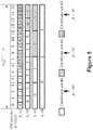
- Figures 2A and 2Billustrate a search space design that determines a set of search space candidates of E-PDCCH based on an aggregation level of DCI and based on predetermined spacing between adjacent search space candidates, according to various embodiments.
- FIG. 2A and 2Bshows a search space design that may be used by encoder module 132 for encoding DCI, in various embodiments.
- N VRB E ⁇ PDCCHis the total number of VRBs available as E-PDCCH resources for a specific UE.
- M( ⁇ )is the number of search space candidates to monitor in the given set of E-PDCCH resources.
- the parameter ⁇ ⁇ , N VRB E ⁇ PDCCHis the VRB gap between two continuous search space candidates at aggregation level ⁇ within N VRB E ⁇ PDCCH VRBs configured and/or allocated by eNB 104.
- eNB 104may encode DCI into one or more VRBs within evenly distributed search space candidates for aggregation level 1 and 2 according to Equation 1, so that frequency scheduling gain may be achieved by eNB 104 scheduling.
- Encoder module 132 of eNB 104may use Equation 1 to select one or more VRBs. ⁇ VRB E ⁇ PDCCH ⁇ k , from a set of E-PDCCH resources, N VRB , Base E ⁇ PDCCH , so eNB 104 may encode DCI onto selected ones of VRBs of the available resources. eNB 104 may then map the encoded VRBs with a mapper module 130, to PRBs for transmission to UE 108.
- the VRB gap between each continuous or adjacent search space candidateshown as one or more grey boxes enclosed by a dark-lined box) for aggregation level 1 is 2 VRBs, for aggregation level 2 is 1 VRB, for aggregation level 4 is 4 VRBs. and for aggregation level 8 is 0 VRBs.
- eNB 104may use Equation 1 to determine into which VRBs, ⁇ VRB E ⁇ PDCCH ⁇ k , of the set of VRBs, N VRB , Base E ⁇ PDCCH , DCI will be encoded. For example, according to Equation 1, eNB 104 may determine that for aggregation level 1, DCI may be encoded into VRBs with index numbers 0, 3, 6, 9, 12, and/or 15, according to one embodiment. eNB 104 may determine that for aggregation level 2, DCI may be encoded into VRBs with index numbers 0, 1, 3, 4, 6, 7, 9, 10, 12, 13, 15, and 16, according to one embodiment. Other aggregation levels are shown in Figure 2A .
- eNB 104may concurrently transmit DCI of one or more aggregation levels to enable communication between eNB 104 and UE 108.
- eNB 104may vary the aggregation level of DCI transmissions based on a power level used for the transmissions. For example, while transmitting at higher power levels, eNB 104 may transmit DCI of aggregation levels 1 and 2, in embodiments. eNB 104 may transmit DCI of aggregation levels 4 and 8 while transmitting at lower power levels, in other embodiments.
- eNB 104may determine search space candidates of Figure 2B based on Equation 1.
- Base E ⁇ PDCCH16
- M( ⁇ )is the number of search space candidates to monitor in the given search space for a particular aggregation level ⁇ .
- eNB 104may not use Equation 2 while N VRB E ⁇ PDCCH > 16 to determine the gaps between search space candidates and instead may evenly distribute the candidates between the VRBs allocated to the search space based on a maximum distance each search space candidate may be positioned away from other search space candidates within the VRB resources, N VRB E ⁇ PDCCH :
- eNB 104may determine that for aggregation level 1, DCI may be encoded into VRBs with index numbers 0, 4, 8, 12, 16, and 20, according to one embodiment. eNB 104 may determine that for aggregation level 2, DCI may be encoded into VRBs with index numbers 0, 1, 4, 5, 8, 9, 12, 13, 16, 17, 20, and 21, according to one embodiment.
- Example distributions of search candidates in E-PDCCH resources, N VRB E ⁇ PDCCH , for aggregation levels 4 and 8are shown in Figure 2B .
- the VRB gap between each continuous or adjacent search space candidatesshown as one or more grey boxes).for aggregation level 1 is 1 VRB, for aggregation level 2 is 0 VRBs, for aggregation level 4 is 4 VRBs, and for aggregation level 8 is 0 VRBs.
- Example distributions of E-PDCCH candidates in search space resources, N VRB , Base E ⁇ PDCCH , for aggregation levels 4 and 8are shown in Figure 3A .
- eNB 104may use Equation 2 to determine that VRB gaps, ⁇ ⁇ N VRB E ⁇ PDCCH , may be ⁇ 2,1,8,4 ⁇ for respective aggregation levels ⁇ 1,2,4,8 ⁇ , according to one embodiment.
- eNB 104may use Equation 1 to determine into which VRBs, ⁇ VRB E ⁇ PDCCH ⁇ k , of the set of VRBs, N VRB E ⁇ PDCCH , DCI will be encoded. For example; according to Equation 1, eNB 104 may determine that for aggregation level 1, DCI may be encoded into VRBs with index numbers 0, 3, 6, 9, 12, and 15, according to one embodiment. eNB 104 may determine that for aggregation level 2, DCI may be encoded into VRBs with index numbers 0, 1, 3, 4, 6, 7, 9, 10, 12, 13, 15, any 16, according to one embodiment. Search space candidates for other aggregation levels are shown in Figure 3B .
- FIG. 4Ashows a search space design that eNB 104 may define in accordance with an equation that is different than Equation 1.
- ⁇ VRB E ⁇ PDCCH ⁇ kmay still represent an index number of the VRB into which DCI may be encoded.
- ⁇⁇ N VRB E ⁇ PDCCH M ⁇ ⁇ ⁇ N VRB E ⁇ PDCCH and M( ⁇ ) may be the same as discussed above.
- eNB 104may use Equation 3 to determine the VRB index numbers into which DCI may be encoded, as shown in Figure 4A .
- Equation 3eNB 104 may determine that for aggregation level 1, DCI may be encoded into VRBs with index numbers 0, 2, 4, 6, 8, 10, according to one embodiment.
- eNB 104may determine that for aggregation level 2, DCI may be encoded into VRBs with index numbers 0-11, According to one embodiment.
- Example distributions of search space candidates in E-PDCCH resources, N VRB E ⁇ PDCCH , for aggregation levels 4 and 8are shown in Figure 4A .
- eNB 104may use Equation 3 to determine the VRB index numbers into which DCI may be encoded, as sHown in Figure 4B .
- Equation 3eNB 104 may determine that for aggregation level 1, DCI may be encoded into VRBs with index numbers 0, 4,.8, 12, 16, and 20, according to one embodiment.
- eNB 104may determine that for aggregation level 2, DCI may be encoded into VRBs with index numbers 0, 1, 4, 5, 8, 9, 12, 13, 16, 17, 20, 21, according to one embodiment.
- Example distributions of E-PDCCH candidates in E-PDCCH resources, N VRB E ⁇ PDCCH , for aggregation levels 4 and 8are shown in Figure 4B .
- Figure 5shows a search space design that eNB 104 may define by using an equation other than Equations 1 and 3.
- eNB 104may provide information to UE 108 that indicates where a search space candidate set will begin and how many VRBs the search space candidate set will occupy.
- eNB 104may provide a 2-bit candidate identifier, such as ⁇ ( ⁇ ), to UE 108 via message authentication code (MAC) or radio resource control (RRC) signaling.
- MACmessage authentication code
- RRCradio resource control
- the other parameters of Equation 4may have the same meaning as above.
- Figure 6shows flow diagram of a method of operating eNB 104, according to embodiments.
- Block 602may include determining a set of search space candidates of an E-PDCCH based on an aggregation level of DCI, a number of VRBs of the E-PDCCH, and a candidate set identifier, the set of search space candidates to be potential bearers of DCI.
- encoder module 132may perform the determining.
- Block 604may include selecting one or more VRBs from the set of search space candidates.
- Block 606may include encoding DCI onto ones of the number of VRBs associated with the set of search space candidates.
- Block 608may include mapping the number of VRBs of the E-PDCCH to physical resource blocks (PRBs) for transmission to a user equipment in a downlink frame.
- PRBsphysical resource blocks
- Figure 7shows a flow diagram of a method of operating eNB 104, according to embodiments.
- Block 702may include determining a set of search space candidates of an E-PDCCH based on an aggregation level of DCI, a number of VRBs of the E-PDCCH, and a candidate set identifier, the set of search space candidates to be potential bearers of DCI.
- Block 704may include selecting one or more VRBs from the set of search space candidates.
- Block 706may include encoding DCI onto a subset of the number of VRBs associated with the set of search space candidates.
- encodingmay include distributing the subset with equal predetermined spacing between the number of VRBs.
- Block 708may include mapping the number of VRBs of the E-PDCCH to physical resource blocks (PRBs) for transmission to a user equipment in a downlink frame.
- PRBsphysical resource blocks
- FIG. 8illustrates, for one embodiment, an example system 800 comprising one or more processor(s) 804, system control logic 808 coupled with at least one of the processor(s) 804, system memory 812 coupled with system control logic 808, non-volatile memory (NVM)/storage 816 coupled with system control logic 808, and a network interface 820 coupled with system control logic 808.
- processor(s) 804system control logic 808 coupled with at least one of the processor(s) 804, system memory 812 coupled with system control logic 808, non-volatile memory (NVM)/storage 816 coupled with system control logic 808, and a network interface 820 coupled with system control logic 808.
- NVMnon-volatile memory
- Processor(s) 804may include one or more single-core or multi-core processors. Processor(s) 804 may include any combination of general-purpose processors and dedicated processors (e.g., graphics processors, application processors, baseband processors, etc.). In an embodiment in which the system 800 implements UE 108, processors(s) 804 may include processor module 148 and be configured to identify and decode search space candidates of the embodiments of Figures 2-5 in accordance with various embodiments. In an embodiment in which the system 800 implements eNB 104, processor(s) 804 may include processor module 120 and be configured to identify and encode DCI into search space candidates of the embodiments of Figures 2-5 in accordance with various embodiments.
- processors(s) 804may include processor module 120 and be configured to identify and encode DCI into search space candidates of the embodiments of Figures 2-5 in accordance with various embodiments.
- System control logic 808may include any suitable interface controllers to provide for any suitable interface to at least one of the processor(s) 804 and/or to any suitable device or component in communication with system control logic 808.
- System control logic 808 for one embodimentmay include one or more memory controller(s) to provide an interface to system memory 81-2.
- System memory 812may be used to load and store data and/or instructions, for example, for system 800.
- System memory 812 for one embodimentmay include any suitable volatile memory, such as suitable dynamic random access memory (DRAM), for example.
- DRAMdynamic random access memory
- NVM/storage 816may include one or more tangible, non-transitory computer-readable media used to store.data and/or instructions, for example.
- NVM/storage 816may include any suitable non-volatile memory, such as flash memory, for example, and/or may include any suitable non-volatile storage device(s), such as one or more hard disk drive(s) (HDD(s)), one or more compact disk (CD) drive(s), and/or one or more digital versatile disk (DVD) drive(s), for example.
- HDDhard disk drive
- CDcompact disk
- DVDdigital versatile disk
- the NVM/storage 816may include a storage resource physically part of a device on which the system 800 is installed or it may be accessible by, but not necessarily a part of, the device.
- the NVM/storage 816may be accessed over a network via the networks interface 820.
- System memory 812 and NVM/storage 816may respectively include, in particular, temporal and persistent copies of instructions 824.
- Instructions 824may include instructions that when executed by at least one of the processor(s) 804 result in the system 800 implementing a one of the search space designs of Figures 2-5 and/or the methods of Figure 6-7 , described herein.
- instructions 824, or hardware, firmware, and/or software components thereofmay additionally/alternatively be located in the system control logic 808, the network interface 820, and/or the processor(s) 804.
- Network interface 820may have a transceiver 822 to provide a radio interface for system 800 to communicate over one or more network(s) and/or with any other suitable device.
- the transceiver 822may be implement receiver module 112 and/or transmitter module 116.
- the transceiver 822may be integrated with other components of system 800.
- the transceiver 822may include a processor of the processor(s) 804, memory of the system memory 812, and NVM/Storage of NVM/Storage 816.
- Network interface 820may include, any suitable hardware and/or firmware.
- Network interface 820may include a plurality of antennas to provide a multiple input, multiple output radio interface.
- Network interface 820for one embodiment may include, for example, a network adapter, a wireless network adapter, a telephone modem, and/or a wireless modem.
- At least one of the processor(s) 804may be packaged together with logic for one or more controller(s) of system control logic 808.
- at least one of the processor(s) 804may be packaged together with logic for one or more controllers of system control logic 808 to form a System in Package (SiP).
- SiPSystem in Package
- at least one of the processor(s) 804may be integrated on the same die with logic for one or more controller(s) of system control logic 808.
- at least one of the processor(s) 804may be integrated on the same die with logic for or more controller(s) of system control logic 808 to form a System on Chip (SoC).
- SoCSystem on Chip
- the system 800may further include input/output (I/O) devices 832.
- the I/O devices 832may include user interfaces designed to enable user interaction with the system 800, peripheral component interfaces designed to enable peripheral component interaction with the system 800, and/or sensors designed to determine environmental conditions and/or location information related to the system 800.
- the user interfacescould include, but are not limited to, a display (e.g., a liquid crystal display, a touch screen display, etc.), a speaker, a microphone, one or more cameras (e.g., a still camera and/or a video camera), a flashlight (e.g., a light emitting diode flash), and a keyboard.
- a displaye.g., a liquid crystal display, a touch screen display, etc.
- a speakere.g., a microphone
- one or more camerase.g., a still camera and/or a video camera
- a flashlighte.g., a light emitting diode flash
- the peripheral component interfacesmay include, but are not limited to, a non-volatile memory port, an audio jack, and a power supply interface.
- the sensorsmay include, but are not limited to, a gyro sensor, an accelerometer, a proximity sensor, an ambient light sensor, and a positioning unit.
- the positioning unitmay also be part of, or interact with, the network interface 820 to communicate with components of a positioning network, e.g., a global positioning system (GPS) satellite.
- GPSglobal positioning system
- system 800may be a mobile computing device such as, but not limited to, a laptop computing device, a tablet computing device, a-netbook, a smartphone, etc. In various embodiments, system 800 may have more or less components, and/or different architectures.
- an apparatusmay include an encoder configured to determine a set of search space candidates of an enhanced - physical downlink control channel (E-PDCCH) based on an aggregation level of downlink control information (DCI), predetermined spacing between adjacent search space candidates, and a number of virtual resource blocks (VRBs) of the E-PDCCH, the set of search space candidates to be potential bearers of DCI.
- the encodermay be configured to select one or more VRBs from the set of search space candidates, and encode DCI onto the selected VRBs.
- the apparatusmay also include a mapper configured to map the VRBs of the E-PDCCH to physical resource blocks (PRBs) for transmissions to a user equipment in a downlink frame.
- PRBsphysical resource blocks
- the apparatusmay include an eNodeB.
- the PRBsmay include a number of resource blocks from a physical downlink shared channel (PDSCH) associated with the E-PDCCH.
- PDSCHphysical downlink shared channel
- the PDSCHmay be defined by release 10 of 3rd Generation Partnership Project's (3GPP) long term evolution advanced (LTE-A) communication standard.
- 3GPP3rd Generation Partnership Project's
- LTE-Along term evolution advanced
- the predetermined spacing between the selected VRBsmay be based on an even distribution of the selected VRBs between the number of VRBs of the E-PDCCH.
- the encodermay be further configured to determine the predetermined spacing between the selected VRBs based on the aggregation level of the DCI.
- the aggregation levelmay be one of multiple DCI aggregation levels including a first, second, third, and fourth DCI aggregation level.
- the encodermay be configured to select one or more VRB from the adjacent search space candidates associated with the aggregations level.
- the encodermay be configured to select one or more VRBs from the set of search space candidates to ensure a lowest index of VRBs for each E-PDCCH, transmission is a multiple of 2.
- ⁇may be one of multiple aggregation levels.
- ⁇ VRB E ⁇ PDCCH ⁇ kmay be an index number of one of the number of VRBs for E-PDCCH transmission associated with the aggregation level ⁇ at a subframe k.
- N VRB , Base E ⁇ PDCCHmay be a baseline number of VRBs, and the encoder may be further configured to insert additional predetermined spacing between the selected VRBs based on a difference between the number of VRBs N RB E ⁇ PDCCH and the baseline number N VRB , Base E ⁇ PDCCH , if the number of VRBs N VRB E ⁇ PDCCH is greater than N VRB , Base E ⁇ PDCCH .
- ⁇may be one of multiple aggregation levels.
- ⁇ VRB E ⁇ PDCCH ⁇ kmay be an index number of one of the number of VRBs for E-PDCCH transmission associated with the one of the multiple aggregation levels ⁇ at subframe k , wherein.
- ⁇may be one of multiple aggregation levels.
- ⁇ VRB E ⁇ PDCCH ⁇ kmay be an index number of one of the number of VRBs for E-PDCCH transmission associated with the one of the multiple aggregation levels ⁇ at a subframe k .
- N VRB E ⁇ PDCCHmay be the number of the VRBs allocated for E-PDCCH, transmission.
- m0, ..., M( ⁇ )-1.
- ⁇may be one of multiple aggregation levels.
- ⁇ VRB E ⁇ PDCCH ⁇ kmay be an index number of one of the number of VRBs to receive DCI associated with the one of the multiple aggregation levels A at a subframe k.
- ⁇is the aggregation level of DCI.
- ⁇ VRB E ⁇ PDCCH ⁇ kmay be an index number of one of the number of VRBs for E-PDCCH transmission associated with the aggregation level A at subframe k.
- ⁇ ( ⁇ )may be the candidate set identifier.
- a base stationmay include an antenna, and any of the disclosed example embodiments of an apparatus.
- an article of manufacture having one or more computer readable mediamay include a number of instructions which, when executed by one or more processors, may cause an apparatus to determine a set of search space candidates of an enhanced-physical downlink control channel (E-PDGCH) based on an aggregation level of downlink control information (DCI), number of virtual resource blocks (VRBs) of the E-PDCCH, and a candidate set identifier, the set of search space candidates to be potential bearers of DCI.
- the instructionsmay cause the apparatus to select one or more VRBs from the set of search space candidates, and encode DCI onto ones of the number of VRBs associated with the set of search space candidates.
- the instructionsmay cause the apparatus to map the number of VRBs of the E-PDCCH to physical resource blocks (PRBs) for transmission to a user equipment in a downlink frame.
- PRBsphysical resource blocks
- the apparatusmay include an eNodeB.
- the instructionsmay cause an encoder module of the apparatus to determine the set of search space candidates, select the one or more VRBs, and encode the DCI.
- the instructionsmay cause the one or more processors to distribute the subset with equal predetermined spacing between the number of VRBs.
- a base stationmay include an antenna, and a computing system configured to execute instructions of an article of manufacture disclosed in other embodiments.
- an apparatusmay include a communications module configured to receive one or more downlink transmissions from a base station via an enhanced-physical downlink control channel (E-PDCCH).
- the apparatusmay include a decoder module coupled to the communications module and configured to identify a set of search space candidates based on aggregation levels of downlink control information (DCI) and a number of virtual resource blocks (VRBs) of the E-PDCCH, and configured to blindly decode the set of search space candidates to retrieve the DCI.
- DCIdownlink control information
- VRBsvirtual resource blocks
- the decoder modulemay be further configured to determine a number of gaps of VRBs between adjacent ones of the search space candidates based on the aggregation levels and the number of VRBs.
- the search space candidatesmay have been equally spaced among the number of VRBs in a first and a second of the aggregations levels.
- one of the decoder module or the communications modulemay determine which of the aggregation levels of DCI to decode based on a strength of a received communication signal from an eNodeB.
Landscapes
- Engineering & Computer Science (AREA)
- Signal Processing (AREA)
- Computer Networks & Wireless Communication (AREA)
- Quality & Reliability (AREA)
- Multimedia (AREA)
- Mobile Radio Communication Systems (AREA)
- General Factory Administration (AREA)
- Information Retrieval, Db Structures And Fs Structures Therefor (AREA)
- Multi-Process Working Machines And Systems (AREA)
Description
- Embodiments of the present invention relate generally to the field of communications, and more particularly, to search space determination in wireless communication, networks.
- 3rd Generation Partnership Project's (3GPP) long term evolution-advanced (LTE-A) wireless communication standard may be modified to add support for multi-user multiple-input multiple-output (MU-MIMO) systems. As a result, base stations may be able to schedule more mobile devices, e.g., user equipment (UE), into each LTE-A subframe during MU-MIMO operations. Scheduling more UEs may decrease physical downlink control channel (PDCCH) resources available for downlink scheduling.
Releases - NEC GROUP, "DL control channel enhancements for Rel-11", 3GPP DRAFT; R1-112135, 3RD GENERATION PARTNERSHIP PROJECT (3GPP), MOBILE COMPETENCE CENTRE ; 650, ROUTE DES LUCIOLES ; F-06921 SOPHIA-ANTIPOLIS CEDEX ; FRANCE, (20110816), vol. RAN WG1, no. Athens, Greece relates to design considerations for E-PDCCH.
- Embodiments of the invention are illustrated by way of example, and not by way of limitation, in the figures of the accompanying drawings in which like reference numerals refer to similar elements;
Figure.1 schematically-illustrates a wireless communication network in accordance with various embodiments.Figures 2A-2B illustrate diagrams of search space candidate allocation in accordance with various embodiments.Figures 3A-3B illustrate diagrams of search space candidate allocation in accordance with various embodiments.Figures 4A-4B illustrate diagrams of search space candidate allocation in accordance with various embodiments.Figure 5 illustrates a diagram of a search space candidate allocation in accordance with various embodiments.Figure 6 illustrates a flow diagram of a method of operating a base station in accordance with various embodiments.Figure 7 illustrates a flow diagram of a method of operating a base station in accordance with various embodiments.Figure 8 schematically depicts an example system in accordance with various embodiments.- Illustrative embodiments of the present disclosure include, but arc not limited to, methods, systems, and apparatuses for search space determination in a wireless communication network.
- Various aspects of the illustrative embodiments will be described using terms commonly employed by those skilled in the art to convey the substance of their work to others skilled in the art. However, it will be apparent to those skilled in the art that some alternate embodiments may be practiced using with portions of the described aspects. For purposes of explanation, specific numbers, materials, and configurations are set forth in order to provide a thorough understanding of the illustrative embodiments. However, it will be apparent to one skilled in the art that alternate embodiments may be practiced without the specific details. In other instances, well-known features are omitted or simplified in order to not obscure the illustrative embodiments.
- Further, various operations will be described as multiple discrete operations, in turn, in a manner that is most helpful in understanding the illustrative embodiments; however, the order of description should not be construed as to imply that these operations are necessarily order dependent. In particular, these operations need not be performed in the order of presentation.
- The phrase "in one embodiment" is used repeatedly. The phrase generally does not refer to the same embodiment; however, it may. The terms "comprising," "having," and "including" are synonymous, unless the context dictates otherwise. The phrase "A/B" means "A or B". The phrase "A and/or B" means "(A), (B), or (A and B)". The phrase "at least one of A, B and C" means "(A), (B), (C),.(A and B), (A and C), (B and C) Or (A, B and C)". The phrase "(A) B" means "(B) or (A B)", that is, A is optional.
- Although specific embodiments have been illustrated and described herein, it will be appreciated by those of ordinary skill in the art that a wide variety of alternate and/or equivalent implementations may be substituted for the specific embodiments shown and described, without departing from the scope of the embodiments of the present disclosure. This application is intended to cover any adaptations or variations of the embodiments discussed herein.
- As used herein, the term "module" may refer to, be part of, or include an Application Specific Integrated Circuit (ASIC), an electronic circuit, a processor (shared, dedicated, or group) and/or memory (shared, dedicated, or group) that execute one or more software or firmware programs, a combinational logic circuit, and/or other suitable components that provide the described functionality.
Figure 1 schematically illustrates awireless communication network 100 in accordance with various embodiments. Wireless communication network 100 (hereinafter "network 100") may be an access network of a 3rd Generation Partnership Project (3GPP) long-term evolution (LTE) network such as evolved universal mobile telecommunication system (UMTS) terrestrial radio access network (E-UTRAN). Thenetwork 100 may include a base station, e.g., enhanced node base station (eNB) 104, configured to wirelessly communicate with a mobile device or terminal, e.g., user equipment (UE) 108. While embodiments of the present invention arc described with reference to an LTE network, some embodiments may be used with other types of wireless access networks.- eNB 104 may be configured to overcome the gain limitations associated with using PDCCH to schedule communications with UE 108, e.g., with MU-MIMO operations. In embodiments, eNB 104 may be configured to increase the number of UEs 108 that may be scheduled during LTE wireless communications by expanding downlink control information (DCI) transmissions into physical downlink shared channel (PDSCH) space, which historically may not have been used for such purpose. In particular, eNB 104 may be configured to determine, define, and/or allocate search space candidates (i.e., potential bearers of DCI) by defining a control space in PDSCH space. This new control space may be included within an enhanced-physical downlink control channel (E-PDCCH), at least because E-PDCCH operation may expand and enhance the capability of PDCCH operation.
- In embodiments, E-PDCCH may be associated with PDSCH such that E-PDCCH operations consume a portion of PDSCH resource blocks. In other embodiments, resource blocks that were allocated to PDSCH in prior 3GPP LTE releases may be removed from the definition of PDSCH and be allocated to E-PDSCH, as resource blocks that are independent of PDSCH. ln embodiments, E-PDCCH may be defined to consume some of the resource blocks allocated to PDCCH and some of the resource blocks allocated to PDSCH such that PDCCH, E-PDCCH, and PDSCH are concurrently allocated some of the same resource blocks.
- eNB 104 may include a
receiver module 112, atransmitter module 116, and aprocessor module 120. eNB 104 may usereceiver module 112 to receive signals from UE 108 eNB 104 may usetransmitter module 116 to transmit signals to UE 108.Receiver module 112 andtransmitter module 116 may receive and transmit signals using one ormore antennas 124.Processor module 120 may be coupled toreceiver module 112 to receive information from UE 108 and may be coupled totransmitter module 116 to transmit information to UE 108. Processor module 120 may include a communication module 128.Processor module 120 may be configured to initiate and maintain communications with UE 108 via communication module 128. Communication module 128 may include amapper module 130 configured to map a number of virtual resource blocks (VRBs) associated with a particular search space design to a number of physical resource blocks (PRBs) allocated for the search space. Communication module 128 may be configured to transmit signals to UE 108 through one or more of a PDSCH, PDCCH, and E-PDCCH.- E-PDCCH may be introduced in the PDSCH region, using physical resource block (PRB)-based (instead of control channel element (CCE)-based) multiplexing. E-PDCCH may be used to increase the PDCCH capacity and bolster enhanced inter-cell interference coordination (eICIC) support in heterogeneous network (hetnet) scenarios. The inability to perform ICIC on legacy PDCCH systems may be due to PDCCH interleaving. In other words, PDCCH CCEs that are used for the transmission of DCI formats may be distributed over the whole bandwidth (BW) of the channel in an irregular fashion, and may make ICIC difficult to perform. By contrast, E-PDCCH in the PDSCH region may be PRB-based and therefore extend the benefit supporting frequency-domain ICIC. As will be discussed in more detail below, in embodiments, E-PDCCH may be implemented by defining and/or allocating the search space for
UE 104. Processor module 120 may also include anencoder module 132.Encoder module 132 may be configured as an encoder and may define various parameters of the search space. A search space may be the set of resources to be tracked byUE 108 during. PDCCH blind decoding. Search space design may be one of many aspects of E-PDCCH operation. Relay-PDCCH (R-PDCCH) was introduced inrelease 10 of 3GPP LTE-A and may provide an established basis from which E-PDCCH may be implemented inrelease 11 of 3GPP LTE-A. However, E-PDCCH may provide significant gain advantages over R-PDCCH. For example, both frequency diversity gain and frequency scheduling gain may be utilized in E-PDCCH operations concurrently. As another example, E-PDCCH may enableUE 108 to fully exploit channel dependent E-PDCCH scheduling gain, which may be useful for smaller aggregation levels (e.g.,aggregation levels 1 and 2). As used herein, the aggregation level may be defined as the number of CCEs aggregated to transmit one DCI format. In subsequent figures, embodiments of E-PDCCH search space designs are described. One advantage of the hereinafter described embodiments may be that the search space may be spread across all potential assigned physical resource blocks (PRBs) for E-PDCCH configured byeNB 104 and may enable more UEs to be scheduled over already existing resources.- In
LTE release 10, one set of virtual resource blocks (VRBs) for backhaul control information may have been semi-statically configured by higher layers on a Relay-Node (RN) specific basis.Release 8 search space methodology was reused for the R-PDCCH design ofLTE release 10. However, few, if any, optimization considerations of utilizing frequency scheduling gain for R-PDCCH were included inrelease 10. To enable frequency scheduling gain in low aggregation levels, herein described techniques may be used to spread search space candidates across the allocated VRBs. - In the
UE 108,processor module 148 may be coupled toreceiver module 136 andtransmitter module 140 and be configured to decode and encode information transmitted in signals communicated between theUE 108 and theeNB 104. Processor module may include acommunication module 152 and adecoder module 156.Processor module 148 may be configured to usecommunication module 152 to receive data and/or control information fromeNB 104 via any one or more of PDCCH, PDSCH, and E-PDCCH.Decoder module 156 may be coupled tocommunications module 152 and be configured to decode downlink control information (DCI) carried by a number of VRBs. The VRBs may be allocated as.search space candidates of the E-PDCCH. Additionally, decoder module 126 may be configured to skip over the one or more VRB gaps that may be positioned between adjacent ones of the search space candidates and check the search space candidates defined by the search space as pertinent toUE 108. By skipping over gaps of VRBs,decoder module 156 may enableUE 108 to reduce computing cycles and reduce power consumption. Figures 2A and 2B illustrate a search space design that determines a set of search space candidates of E-PDCCH based on an aggregation level of DCI and based on predetermined spacing between adjacent search space candidates, according to various embodiments.Figures 2A and 2B shows a search space design that may be used byencoder module 132 for encoding DCI, in various embodiments. The UE-specific search space
eNB 104 for potential DCI transmission are given by:
- In
Equation 1,


eNB 104. In embodiments,

- According to embodiments of the disclosure,
eNB 104 may encode DCI into one or more VRBs within evenly distributed search space candidates foraggregation level Equation 1, so that frequency scheduling gain may be achieved byeNB 104 scheduling. Encoder module 132 ofeNB 104 may useEquation 1 to select one or more VRBs.

eNB 104 may encode DCI onto selected ones of VRBs of the available resources.eNB 104 may then map the encoded VRBs with amapper module 130, to PRBs for transmission toUE 108.eNB 104 may determine the search space candidates ofFigure 2A based onEquation 1. For the search space design ofFigure 2A ,eNB 104 may determine that 6 search space candidates may be distributed in each ofaggregation levels eNB 104 may determine that 2 search space candidates may be distributed in each ofaggregation levels eNB 104 may determine that 16 VRBs are allocated as a baseline number of VRBs,
eNB 104 may determine the baseline gaps between search space candidates to be:

aggregation level 1 is 2 VRBs, foraggregation level 2 is 1 VRB, foraggregation level 4 is 4 VRBs. and foraggregation level 8 is 0 VRBs.eNB 104 may useEquation 1 to determine into which VRBs,

Equation 1,eNB 104 may determine that foraggregation level 1, DCI may be encoded into VRBs withindex numbers eNB 104 may determine that foraggregation level 2, DCI may be encoded into VRBs withindex numbers Figure 2A .eNB 104 may concurrently transmit DCI of one or more aggregation levels to enable communication betweeneNB 104 andUE 108.eNB 104 may vary the aggregation level of DCI transmissions based on a power level used for the transmissions. For example, while transmitting at higher power levels,eNB 104 may transmit DCI ofaggregation levels eNB 104 may transmit DCI ofaggregation levels eNB 104 may determine search space candidates ofFigure 2B based onEquation 1. With reference toFigure 2B , for E-PDCCH having a set of resources, e.g.


Equation 2, the baseline VRB gaps,
Figure 2A , i.e,
Figure 2A , i.e.,
- According to another embodiment,
eNB 104 may not useEquation 2 while

- According to one embodiment, for 24 E-PDCCH resources, i.e.,

eNB 104 may determine the gaps between each of the continuous search space candidates to be
eNB 104 may useEquation 1 to determine into which VRBs,

Equation 1,eNB 104 may determine that foraggregation level 1, DCI may be encoded into VRBs withindex numbers eNB 104 may determine that foraggregation level 2, DCI may be encoded into VRBs withindex numbers 
aggregation levels Figure 2B . Figure 3A shows a search space design in whicheNB 104 determines, based onEquation 1, determines the VRB baseline gaps to be

aggregation level 1 is 1 VRB, foraggregation level 2 is 0 VRBs, foraggregation level 4 is 4 VRBs, and foraggregation level 8 is 0 VRBs.eNB 104 may useEquation 1 to determine into which VRBs,

Equation 1,eNB 104 may determine that foraggregation level 1, DCI may be encoded into VRBs withindex numbers eNB 104 may determine that foraggregation level 2, DCI may be encoded into VRBs with index numbers 0-11, according to one embodiment. Example distributions of E-PDCCH candidates in search space resources,
aggregation levels Figure 3A .Figure 3B shows another search space design that may be based onEquation 1 in the event thateNB 104 configures 24 VRBs for E-PDCCH transmission, i.e.,

eNB 104 according toEquation 2, as discussed above.- For the search space design show in
Figure 3B ,eNB 104 may useEquation 2 to determine that VRB gaps,
eNB 104 may useEquation 1 to determine into which VRBs,

Equation 1,eNB 104 may determine that foraggregation level 1, DCI may be encoded into VRBs withindex numbers eNB 104 may determine that foraggregation level 2, DCI may be encoded into VRBs withindex numbers Figure 3B .Figure 4A shows a search space design thateNB 104 may define in accordance with an equation that is different thanEquation 1. According to various embodiments,eNB 104 may distribute search space candidates evenly withinaggregation levels 
Equation 3,

Figure 4A shows that if
eNB 104 may determine the gaps between adjacent search space candidates to be at least {1,0,4,0} for corresponding aggregation levels {1,2,4,8}, according to one embodiment.eNB 104 may useEquation 3 to determine the VRB index numbers into which DCI may be encoded, as shown inFigure 4A . For example, according toEquation 3,eNB 104 may determine that foraggregation level 1, DCI may be encoded into VRBs withindex numbers eNB 104 may determine that foraggregation level 2, DCI may be encoded into VRBs with index numbers 0-11, According to one embodiment. Example distributions of search space candidates in E-PDCCH resources,
aggregation levels Figure 4A .Figure 4B shows a search space design thateNB 104 may define by usingEquation 3, if
Figure 4A shows that if
eNB 104 may determine the gaps between adjacent search space candidates to be {3,2,8,4} for corresponding aggregation levels {1,2,4,8}, according to one embodiment.eNB 104 may useEquation 3 to determine the VRB index numbers into which DCI may be encoded, as sHown inFigure 4B . For example, according toEquation 3,eNB 104 may determine that foraggregation level 1, DCI may be encoded into VRBs withindex numbers eNB 104 may determine that foraggregation level 2, DCI may be encoded into VRBs withindex numbers 
aggregation levels Figure 4B .Figure 5 shows a search space design thateNB 104 may define by using an equation other thanEquations eNB 104 may provide information toUE 108 that indicates where a search space candidate set will begin and how many VRBs the search space candidate set will occupy.eNB 104 may provide a 2-bit candidate identifier, such as β(Λ), toUE 108 via message authentication code (MAC) or radio resource control (RRC) signaling.eNB 104 may determine search space candidate allocations according to:
candidate set 0, "01" for acandidate set 1, and "10" for acandidate set 2. More or less bits may be used by theeNB 104 to indicate more or less search space candidate sets than are shown inFigure 5 . The other parameters ofEquation 4 may have the same meaning as above.- The above-described techniques expand the capability of PDCCH by using E-PDCCH to schedule DCI for UEs, in various embodiments. Such an approach may enable
eNB 104 to exercise frequency selective scheduling to increase frequency selection gains and frequency diversity gains, according to various embodiments. Figure 6 shows flow diagram of a method of operatingeNB 104, according to embodiments.Block 602 may include determining a set of search space candidates of an E-PDCCH based on an aggregation level of DCI, a number of VRBs of the E-PDCCH, and a candidate set identifier, the set of search space candidates to be potential bearers of DCI. In embodiments,encoder module 132 may perform the determining. In other embodiments, determining the set of search space candidates may be based on


Block 604 may include selecting one or more VRBs from the set of search space candidates.Block 606 may include encoding DCI onto ones of the number of VRBs associated with the set of search space candidates.Block 608 may include mapping the number of VRBs of the E-PDCCH to physical resource blocks (PRBs) for transmission to a user equipment in a downlink frame.Figure 7 shows a flow diagram of a method of operatingeNB 104, according to embodiments.Block 702 may include determining a set of search space candidates of an E-PDCCH based on an aggregation level of DCI, a number of VRBs of the E-PDCCH, and a candidate set identifier, the set of search space candidates to be potential bearers of DCI.Block 704 may include selecting one or more VRBs from the set of search space candidates.Block 706 may include encoding DCI onto a subset of the number of VRBs associated with the set of search space candidates. In embodiments, encoding may include distributing the subset with equal predetermined spacing between the number of VRBs.Block 708 may include mapping the number of VRBs of the E-PDCCH to physical resource blocks (PRBs) for transmission to a user equipment in a downlink frame.eNB 104 andUE 108 described herein may be implemented into a system using any suitable hardware and/or software to configure as desired.Figure 8 illustrates, for one embodiment, anexample system 800 comprising one or more processor(s) 804,system control logic 808 coupled with at least one of the processor(s) 804,system memory 812 coupled withsystem control logic 808, non-volatile memory (NVM)/storage 816 coupled withsystem control logic 808, and anetwork interface 820 coupled withsystem control logic 808.- Processor(s) 804 may include one or more single-core or multi-core processors. Processor(s) 804 may include any combination of general-purpose processors and dedicated processors (e.g., graphics processors, application processors, baseband processors, etc.). In an embodiment in which the
system 800implements UE 108, processors(s) 804 may includeprocessor module 148 and be configured to identify and decode search space candidates of the embodiments ofFigures 2-5 in accordance with various embodiments. In an embodiment in which thesystem 800 implementseNB 104, processor(s) 804 may includeprocessor module 120 and be configured to identify and encode DCI into search space candidates of the embodiments ofFigures 2-5 in accordance with various embodiments. System control logic 808 for one embodiment may include any suitable interface controllers to provide for any suitable interface to at least one of the processor(s) 804 and/or to any suitable device or component in communication withsystem control logic 808.System control logic 808 for one embodiment may include one or more memory controller(s) to provide an interface to system memory 81-2.System memory 812 may be used to load and store data and/or instructions, for example, forsystem 800.System memory 812 for one embodiment may include any suitable volatile memory, such as suitable dynamic random access memory (DRAM), for example.- NVM/
storage 816 may include one or more tangible, non-transitory computer-readable media used to store.data and/or instructions, for example. NVM/storage 816 may include any suitable non-volatile memory, such as flash memory, for example, and/or may include any suitable non-volatile storage device(s), such as one or more hard disk drive(s) (HDD(s)), one or more compact disk (CD) drive(s), and/or one or more digital versatile disk (DVD) drive(s), for example. - The NVM/
storage 816 may include a storage resource physically part of a device on which thesystem 800 is installed or it may be accessible by, but not necessarily a part of, the device. For example, the NVM/storage 816 may be accessed over a network via thenetworks interface 820. System memory 812 and NVM/storage 816 may respectively include, in particular, temporal and persistent copies ofinstructions 824.Instructions 824 may include instructions that when executed by at least one of the processor(s) 804 result in thesystem 800 implementing a one of the search space designs ofFigures 2-5 and/or the methods ofFigure 6-7 , described herein. In some embodiments,instructions 824, or hardware, firmware, and/or software components thereof, may additionally/alternatively be located in thesystem control logic 808, thenetwork interface 820, and/or the processor(s) 804.Network interface 820 may have atransceiver 822 to provide a radio interface forsystem 800 to communicate over one or more network(s) and/or with any other suitable device. Thetransceiver 822 may be implementreceiver module 112 and/ortransmitter module 116. In various embodiments, thetransceiver 822 may be integrated with other components ofsystem 800. For example, thetransceiver 822 may include a processor of the processor(s) 804, memory of thesystem memory 812, and NVM/Storage of NVM/Storage 816.Network interface 820 may include, any suitable hardware and/or firmware.Network interface 820 may include a plurality of antennas to provide a multiple input, multiple output radio interface.Network interface 820 for one embodiment may include, for example, a network adapter, a wireless network adapter, a telephone modem, and/or a wireless modem.- For one embodiment, at least one of the processor(s) 804 may be packaged together with logic for one or more controller(s) of
system control logic 808. For one embodiment, at least one of the processor(s) 804 may be packaged together with logic for one or more controllers ofsystem control logic 808 to form a System in Package (SiP). For one embodiment, at least one of the processor(s) 804 may be integrated on the same die with logic for one or more controller(s) ofsystem control logic 808. For one embodiment, at least one of the processor(s) 804 may be integrated on the same die with logic for or more controller(s) ofsystem control logic 808 to form a System on Chip (SoC). - The
system 800 may further include input/output (I/O)devices 832. The I/O devices 832 may include user interfaces designed to enable user interaction with thesystem 800, peripheral component interfaces designed to enable peripheral component interaction with thesystem 800, and/or sensors designed to determine environmental conditions and/or location information related to thesystem 800. - In various embodiments, the user interfaces could include, but are not limited to, a display (e.g., a liquid crystal display, a touch screen display, etc.), a speaker, a microphone, one or more cameras (e.g., a still camera and/or a video camera), a flashlight (e.g., a light emitting diode flash), and a keyboard.
- In various embodiments, the peripheral component interfaces may include, but are not limited to, a non-volatile memory port, an audio jack, and a power supply interface.
- In various embodiments, the sensors may include, but are not limited to, a gyro sensor, an accelerometer, a proximity sensor, an ambient light sensor, and a positioning unit. The positioning unit may also be part of, or interact with, the
network interface 820 to communicate with components of a positioning network, e.g., a global positioning system (GPS) satellite. - In various embodiments, the
system 800 may be a mobile computing device such as, but not limited to, a laptop computing device, a tablet computing device, a-netbook, a smartphone, etc. In various embodiments,system 800 may have more or less components, and/or different architectures. - According to various example embodiments, an apparatus may include an encoder configured to determine a set of search space candidates of an enhanced - physical downlink control channel (E-PDCCH) based on an aggregation level of downlink control information (DCI), predetermined spacing between adjacent search space candidates, and a number of virtual resource blocks (VRBs) of the E-PDCCH, the set of search space candidates to be potential bearers of DCI. The encoder may be configured to select one or more VRBs from the set of search space candidates, and encode DCI onto the selected VRBs. The apparatus may also include a mapper configured to map the VRBs of the E-PDCCH to physical resource blocks (PRBs) for transmissions to a user equipment in a downlink frame.
- In embodiments, the apparatus may include an eNodeB.
- In embodiments, the PRBs may include a number of resource blocks from a physical downlink shared channel (PDSCH) associated with the E-PDCCH.
- In embodiments, the PDSCH may be defined by
release 10 of 3rd Generation Partnership Project's (3GPP) long term evolution advanced (LTE-A) communication standard. - In embodiments, the predetermined spacing between the selected VRBs may be based on an even distribution of the selected VRBs between the number of VRBs of the E-PDCCH.
- In embodiments, the encoder may be further configured to determine the predetermined spacing between the selected VRBs based on the aggregation level of the DCI.
- In embodiments, the aggregation level may be one of multiple DCI aggregation levels including a first, second, third, and fourth DCI aggregation level.
- In embodiments, the encoder may be configured to select one or more VRB from the adjacent search space candidates associated with the aggregations level.
- In embodiments, the encoder may be configured to select one or more VRBs from the set of search space candidates to ensure a lowest index of VRBs for each E-PDCCH, transmission is a multiple of 2.
- In embodiments, the encoder may be configured to select one or more VRBs from the.set of search space candidates to be potential bearers of DCI to ensure the lowest index of VRBs for each E-PDCCH transmission is a multiple of 2 based based on:


- In embodiments,


- In embodiments, the encoder may be configured to select one or more VRBs from the set of search space candidates to be potential bearers of DCI based on:


- In embodiments, the encoder may be configured to select one or more VRBs from the set of search space candidates to be potential bearers of DCI based on:


- In embodiments, the encoder may be configured to select one or more VRBs from the set of search space candidates based on:


- In embodiments, the encoder may be configured to select one or more VRBs from the set of search space candidates based on:


- According to various example embodiments, a base station may include an antenna, and any of the disclosed example embodiments of an apparatus.
- According to various example embodiments, an article of manufacture having one or more computer readable media may include a number of instructions which, when executed by one or more processors, may cause an apparatus to determine a set of search space candidates of an enhanced-physical downlink control channel (E-PDGCH) based on an aggregation level of downlink control information (DCI), number of virtual resource blocks (VRBs) of the E-PDCCH, and a candidate set identifier, the set of search space candidates to be potential bearers of DCI. The instructions may cause the apparatus to select one or more VRBs from the set of search space candidates, and encode DCI onto ones of the number of VRBs associated with the set of search space candidates. The instructions may cause the apparatus to map the number of VRBs of the E-PDCCH to physical resource blocks (PRBs) for transmission to a user equipment in a downlink frame.
- In embodiments, the apparatus may include an eNodeB.
- In embodiments; the instructions may cause an encoder module of the apparatus to determine the set of search space candidates, select the one or more VRBs, and encode the DCI.
- In embodiments, the instructions may cause the one or more processors to distribute the subset with equal predetermined spacing between the number of VRBs.
- According to various example embodiments, a base station may include an antenna, and a computing system configured to execute instructions of an article of manufacture disclosed in other embodiments.
- According to various example embodiments, an apparatus may include a communications module configured to receive one or more downlink transmissions from a base station via an enhanced-physical downlink control channel (E-PDCCH). The apparatus may include a decoder module coupled to the communications module and configured to identify a set of search space candidates based on aggregation levels of downlink control information (DCI) and a number of virtual resource blocks (VRBs) of the E-PDCCH, and configured to blindly decode the set of search space candidates to retrieve the DCI.
- In embodiments, the decoder module may be further configured to determine a number of gaps of VRBs between adjacent ones of the search space candidates based on the aggregation levels and the number of VRBs.
- In embodiments, the search space candidates may have been equally spaced among the number of VRBs in a first and a second of the aggregations levels.
- In embodiments, one of the decoder module or the communications module may determine which of the aggregation levels of DCI to decode based on a strength of a received communication signal from an eNodeB.
- Although certain embodiments have been illustrated and described herein for purposes of description, a wide variety of alternate and/or equivalent embodiments or implementations calculated to achieve, the same purposes may be substituted for the embodiments shown and described without departing from the scope of the present disclosure. This application is intended to cover any adaptations or variations of the embodiments discussed herein.


Claims (6)
- An apparatus (104) comprising:an encoder (132) configured to:determine a set of search space candidates of an enhanced - physical downlink control channel , E-PDCCH, based on an aggregation level of downlink control information, DCI, predetermined spacing between adjacent search space candidates, and a number of virtual resource blocks, VRBs, of the E-PDCCH, the set of search space candidates to be potential bearers of DCI;select one or more VRBs from the set of search space candidates; andencode DCI onto the selected VRBs; anda mapper (130) configured to map the VRBs of the E-PDCCH to physical resource blocks, PBRs, for transmission to a user equipment (108) in a downlink frame, whereinthe encoder (132) is configured to select one or more VRBs from the set of search space candidates to be potential bearers of DCI to ensure the lowest index of VRBs for each E-PDCCH transmission is a multiple of 2 based on:


- The apparatus (104) of claim 1, wherein the apparatus (104) includes an eNodeB.
- The apparatus (104) of claim 1 or claim 2, wherein the PRBs include a number of resource blocks from a physical downlink shared channel, PDSCH, associated with the E-PDCCH,.
- A computer-implemented method, the method comprising:receiving one or more downlink transmissions from a base station via an enhanced physical downlink control channel, E-PDCCH; identifying a set of search space candidates based on aggregation levels of downlink control information, DCI, a number of virtual resource blocks, VRBSs, of the E-PDCCH; andblindly decoding the set of search space candidates to retrieve the DCI, whereinidentifying the set of search space candidates is based on:


- The computer-implemented method of claim 4, further comprising:determining which of the aggregation levels of DCI to decode based on a strength of a received communication signal from an eNodeB.
- One or more non-transitory computer system-readable media comprising computer system-executable instructions, wherein the instructions, in response to execution by a computer system, cause the computer system to perform the computer-implemented method of claim 4 or claim 5.


Applications Claiming Priority (2)
| Application Number | Priority Date | Filing Date | Title |
|---|---|---|---|
| US201161556109P | 2011-11-04 | 2011-11-04 | |
| PCT/US2012/031039WO2013066386A1 (en) | 2011-11-04 | 2012-03-28 | Search space determination |
Publications (3)
| Publication Number | Publication Date |
|---|---|
| EP2774294A1 EP2774294A1 (en) | 2014-09-10 |
| EP2774294A4 EP2774294A4 (en) | 2015-08-05 |
| EP2774294B1true EP2774294B1 (en) | 2017-10-04 |
Family
ID=86763531
Family Applications (1)
| Application Number | Title | Priority Date | Filing Date |
|---|---|---|---|
| EP12844776.0ANot-in-forceEP2774294B1 (en) | 2011-11-04 | 2012-03-28 | Search space determination |
Country Status (9)
| Country | Link |
|---|---|
| US (1) | US8755348B2 (en) |
| EP (1) | EP2774294B1 (en) |
| JP (1) | JP5885854B2 (en) |
| KR (1) | KR101599058B1 (en) |
| CN (1) | CN103907301B (en) |
| BR (2) | BR112014010606A2 (en) |
| IN (1) | IN2014CN03084A (en) |
| RU (1) | RU2573393C2 (en) |
| WO (1) | WO2013066386A1 (en) |
Cited By (1)
| Publication number | Priority date | Publication date | Assignee | Title |
|---|---|---|---|---|
| US10616895B2 (en) | 2015-06-16 | 2020-04-07 | Huawei Technologies Co., Ltd. | Resource scheduling method, apparatus, and device |
Families Citing this family (47)
| Publication number | Priority date | Publication date | Assignee | Title |
|---|---|---|---|---|
| DK2919545T3 (en) | 2011-02-11 | 2016-12-05 | Interdigital Patent Holdings Inc | Device and method for an improved control channel (E-PDCCH). |
| KR102067060B1 (en)* | 2011-06-29 | 2020-02-11 | 엘지전자 주식회사 | Method and apparatus for transmitting control information in wireless communication system |
| US8582527B2 (en) | 2011-07-01 | 2013-11-12 | Ofinno Technologies, Llc | Hybrid automatic repeat request in multicarrier systems |
| EP2564611B1 (en) | 2011-07-01 | 2015-02-18 | Ofinno Technologies, LLC | Synchronization signal and control messages in multicarrier OFDM |
| US8369280B2 (en) | 2011-07-01 | 2013-02-05 | Ofinno Techologies, LLC | Control channels in multicarrier OFDM transmission |
| US8842637B2 (en) | 2011-12-04 | 2014-09-23 | Ofinno Technologies, Llc | Carrier information transmission to wireless devices |
| KR102402907B1 (en) | 2012-01-27 | 2022-05-30 | 인터디지탈 패튼 홀딩스, 인크 | Systems and/or methods for providing epdcch in a multiple carrier based and/or quasi-collated network |
| US9054843B2 (en)* | 2012-01-30 | 2015-06-09 | Nokia Solutions And Networks Oy | Search space arrangement for control channel |
| PL2826192T3 (en) | 2012-03-16 | 2018-01-31 | Nokia Solutions & Networks Oy | Blind decoding |
| CN103327591A (en) | 2012-03-21 | 2013-09-25 | 北京三星通信技术研究有限公司 | Power control method of SRS |
| US9497756B2 (en) | 2012-03-25 | 2016-11-15 | Comcast Cable Communications, Llc | Base station radio resource management |
| KR102129794B1 (en)* | 2012-04-01 | 2020-07-03 | 엘지전자 주식회사 | Method of tranceiving downlink control channel in wireless communication system and appratus thereof |
| US9949265B2 (en) | 2012-05-04 | 2018-04-17 | Comcast Cable Communications, Llc | Control channel in a wireless communication system |
| WO2013188444A1 (en)* | 2012-06-12 | 2013-12-19 | Interdigital Patent Holdings, Inc. | Method and apparatus for controlling uplink multiple-input multiple-output (mimo) transmissions |
| US9191943B2 (en) | 2012-09-13 | 2015-11-17 | Kt Corporation | Reception and configuration of downlink control channel |
| CN103684673B (en)* | 2012-09-24 | 2018-11-16 | 中兴通讯股份有限公司 | A kind of method and apparatus for detecting control signaling and realizing control signaling detection |
| CN103813459A (en)* | 2012-11-05 | 2014-05-21 | 上海贝尔股份有限公司 | Method and device for determining search space of E-PDCCH (Enhanced Physical Downlink Control Channel) of UE (User Equipment) |
| US10218461B2 (en)* | 2013-10-31 | 2019-02-26 | Panasonic Intellectual Property Corporation Of America | Wireless communication method, eNodeB, and user equipment |
| US9642159B1 (en)* | 2014-07-11 | 2017-05-02 | Sprint Spectrum L.P. | Use of indication in downlink control information messaging to signal presence of additional downlink control information messaging |
| US9992670B2 (en)* | 2014-08-12 | 2018-06-05 | Vodafone Ip Licensing Limited | Machine-to-machine cellular communication security |
| US9572149B1 (en) | 2014-09-03 | 2017-02-14 | Sprint Spectrum L.P. | Use of assigned PDSCH resource to assign PDSCH resource of subsequent TTI |
| US10820314B2 (en) | 2014-12-12 | 2020-10-27 | Qualcomm Incorporated | Traffic advertisement in neighbor aware network (NAN) data path |
| US9949236B2 (en)* | 2014-12-12 | 2018-04-17 | Qualcomm Incorporated | Traffic advertisement in neighbor aware network (NAN) data path |
| US10827484B2 (en) | 2014-12-12 | 2020-11-03 | Qualcomm Incorporated | Traffic advertisement in neighbor aware network (NAN) data path |
| KR102316775B1 (en) | 2015-04-02 | 2021-10-26 | 삼성전자 주식회사 | Method and apparatus for reduction of transmission time interval in wirelss cellular communication system |
| CN113765630B (en) | 2015-04-02 | 2024-02-27 | 三星电子株式会社 | Terminal and base station in wireless communication system and method for performing the same |
| TWI661735B (en)* | 2016-04-05 | 2019-06-01 | 新力股份有限公司 | Terminal device, infrastructure equipment, methods and integrated circuitry |
| US10582406B2 (en)* | 2016-04-20 | 2020-03-03 | Telefonaktiebolaget Lm Ericsson (Publ) | Self-contained scheduled mobility measurement signals |
| US10476650B2 (en) | 2016-08-19 | 2019-11-12 | Qualcomm Incorporated | Control channel with flexible numerology |
| US11523376B2 (en) | 2017-01-05 | 2022-12-06 | Huawei Technologies Co., Ltd. | Method for downlink control channel design |
| WO2018131842A1 (en)* | 2017-01-12 | 2018-07-19 | 엘지전자(주) | Method for transmitting and receiving downlink control information in wireless communication system and device for same |
| BR112019014919A2 (en) | 2017-01-20 | 2020-05-19 | Guangdong Oppo Mobile Telecommunications Corp Ltd | method for reporting available resources for pdsch, method for determining available resources for pdsch, base station and user equipment |
| CN114844608A (en) | 2017-02-17 | 2022-08-02 | 华为技术有限公司 | Multi-transmission node transmission method and communication device |
| US10028210B1 (en) | 2017-03-23 | 2018-07-17 | At&T Intellectual Property I, L.P. | Encoding and decoding data for group common control channels |
| KR102338507B1 (en)* | 2017-08-04 | 2021-12-13 | 삼성전자 주식회사 | Method and apparatus for transmitting and receving downlink control information in wirelss communication system |
| CN109392151B (en)* | 2017-08-11 | 2023-04-18 | 维沃移动通信有限公司 | Method, device and system for determining PDCCH search space |
| CN109995467B (en)* | 2018-01-03 | 2020-09-01 | 电信科学技术研究院 | A resource mapping method, apparatus, and device |
| CN108600541B (en)* | 2018-04-24 | 2020-10-16 | Oppo广东移动通信有限公司 | Drop detection method and related device |
| US11252748B2 (en) | 2018-05-07 | 2022-02-15 | Qualcomm Incorporated | System information for access and backhaul |
| PT3796735T (en) | 2018-05-15 | 2023-10-23 | Ntt Docomo Inc | USER DEVICE, BASE STATION APPARATUS AND METHOD EXECUTED BY A USER DEVICE |
| RU2764228C1 (en)* | 2018-07-13 | 2022-01-14 | Нтт Докомо, Инк. | User terminal and base station |
| CN112544115B (en)* | 2018-08-10 | 2022-07-26 | 华为技术有限公司 | Data scheduling method and communication device |
| KR20200031446A (en)* | 2018-09-14 | 2020-03-24 | 삼성전자주식회사 | Method and apparatus for monitoring physical downlink control channel in wireless communication system |
| US10448342B1 (en)* | 2018-10-19 | 2019-10-15 | Motorola Mobility Llc | Aggregate transmit power limiting on uncoordinated multiple transmitter device |
| CN111225388B (en)* | 2018-11-23 | 2022-03-29 | 大唐移动通信设备有限公司 | Carrier aggregation cell set optimization method and device |
| CN113439480B (en) | 2019-01-11 | 2022-11-04 | Lg 电子株式会社 | Method and apparatus for transmitting and receiving signals in a wireless communication system |
| US11758514B2 (en)* | 2019-12-20 | 2023-09-12 | Qualcomm Incorporated | Physical downlink control channel candidates related to physical downlink control channel repetitions |
Family Cites Families (9)
| Publication number | Priority date | Publication date | Assignee | Title |
|---|---|---|---|---|
| HUE047122T2 (en)* | 2006-11-01 | 2020-04-28 | Qualcomm Inc | Method and apparatus for cell search in an orthogonal wireless communication system |
| KR101104965B1 (en)* | 2008-12-19 | 2012-01-12 | 한국전자통신연구원 | Scheduling Method and Device in Base Station Considering Downlink Control Channel Resource |
| EP4221043A3 (en)* | 2009-09-28 | 2023-08-16 | Samsung Electronics Co., Ltd. | Extending physical downlink control channels |
| KR101761624B1 (en)* | 2010-01-26 | 2017-08-04 | 엘지전자 주식회사 | Method for processing a downlink signal by a relay in a wireless communication system, and an apparatus therefor |
| US20110267948A1 (en)* | 2010-05-03 | 2011-11-03 | Koc Ali T | Techniques for communicating and managing congestion in a wireless network |
| DK2919545T3 (en)* | 2011-02-11 | 2016-12-05 | Interdigital Patent Holdings Inc | Device and method for an improved control channel (E-PDCCH). |
| US8537862B2 (en)* | 2011-06-30 | 2013-09-17 | Blackberry Limited | Transmit downlink control information with higher order modulation |
| US20130058285A1 (en)* | 2011-09-02 | 2013-03-07 | Renesas Mobile Corporation | Spatial hashing for enhanced control channel search spaces |
| US9084238B2 (en)* | 2011-09-12 | 2015-07-14 | Blackberry Limited | Searching space and operation for enhanced PDCCH in LTE systems |
- 2012
- 2012-03-28EPEP12844776.0Apatent/EP2774294B1/ennot_activeNot-in-force
- 2012-03-28BRBR112014010606Apatent/BR112014010606A2/ennot_activeIP Right Cessation
- 2012-03-28USUS13/810,890patent/US8755348B2/ennot_activeExpired - Fee Related
- 2012-03-28JPJP2014539921Apatent/JP5885854B2/ennot_activeExpired - Fee Related
- 2012-03-28RURU2014117686/07Apatent/RU2573393C2/ennot_activeIP Right Cessation
- 2012-03-28CNCN201280054291.1Apatent/CN103907301B/ennot_activeExpired - Fee Related
- 2012-03-28KRKR1020147011908Apatent/KR101599058B1/ennot_activeExpired - Fee Related
- 2012-03-28ININ3084CHN2014patent/IN2014CN03084A/enunknown
- 2012-03-28BRBR112014010784Apatent/BR112014010784A2/ennot_activeIP Right Cessation
- 2012-03-28WOPCT/US2012/031039patent/WO2013066386A1/enactiveApplication Filing
Non-Patent Citations (1)
| Title |
|---|
| None* |
Cited By (4)
| Publication number | Priority date | Publication date | Assignee | Title |
|---|---|---|---|---|
| US10616895B2 (en) | 2015-06-16 | 2020-04-07 | Huawei Technologies Co., Ltd. | Resource scheduling method, apparatus, and device |
| US10645697B2 (en) | 2015-06-16 | 2020-05-05 | Huawei Technologies Co., Ltd. | Resource scheduling method, apparatus, and device |
| US10939435B2 (en) | 2015-06-16 | 2021-03-02 | Huawei Technologies Co., Ltd. | Resource scheduling method, apparatus, and device |
| US11425716B2 (en) | 2015-06-16 | 2022-08-23 | Huawei Technologies Co., Ltd. | Resource scheduling method, apparatus, and device |
Also Published As
| Publication number | Publication date |
|---|---|
| CN103907301B (en) | 2017-09-12 |
| IN2014CN03084A (en) | 2015-07-03 |
| BR112014010606A2 (en) | 2017-04-25 |
| RU2014117686A (en) | 2015-11-10 |
| JP2014533034A (en) | 2014-12-08 |
| EP2774294A4 (en) | 2015-08-05 |
| RU2573393C2 (en) | 2016-01-20 |
| KR20140084110A (en) | 2014-07-04 |
| CN103907301A (en) | 2014-07-02 |
| BR112014010784A2 (en) | 2018-06-19 |
| US20130163551A1 (en) | 2013-06-27 |
| JP5885854B2 (en) | 2016-03-16 |
| KR101599058B1 (en) | 2016-03-02 |
| WO2013066386A1 (en) | 2013-05-10 |
| US8755348B2 (en) | 2014-06-17 |
| EP2774294A1 (en) | 2014-09-10 |
Similar Documents
| Publication | Publication Date | Title |
|---|---|---|
| EP2774294B1 (en) | Search space determination | |
| US9054843B2 (en) | Search space arrangement for control channel | |
| US9143984B2 (en) | Mapping of enhanced physical downlink control channels in a wireless communication network | |
| CN104012011B (en) | Signaling for configuration of downlink coordinated multi-point communication | |
| CN108055062B (en) | Transmission point indication in coordinated multipoint system | |
| CN103959872B (en) | The mapping method and device of the search space of down control channel | |
| EP3373479A1 (en) | Signaling for downlink coordinated multipoint in a wireless communication system | |
| US10342003B2 (en) | Device and method and program for performing radio communication | |
| CN105391517B (en) | The reception of control channel and sending method and device | |
| CN105871429B (en) | Method, apparatus and computer readable medium for transmission point indication in coordinated multipoint system | |
| HK1249286B (en) | Transmission point indication in coordinated multi-point system | |
| HK1228118A (en) | Signaling for downlink coordinated multipoint in a wireless communication system | |
| HK1228118A1 (en) | Signaling for downlink coordinated multipoint in a wireless communication system | |
| HK1191790A (en) | Signaling for downlink coordinated multipoint in a wireless communication system | |
| HK1191790B (en) | Signaling for downlink coordinated multipoint in a wireless communication system | |
| HK1188896A (en) | Signaling for downlink coordinated multipoint in a wireless communication system | |
| HK1188896B (en) | Signaling for downlink coordinated multipoint in a wireless communication system |
Legal Events
| Date | Code | Title | Description |
|---|---|---|---|
| PUAI | Public reference made under article 153(3) epc to a published international application that has entered the european phase | Free format text:ORIGINAL CODE: 0009012 | |
| 17P | Request for examination filed | Effective date:20140502 | |
| AK | Designated contracting states | Kind code of ref document:A1 Designated state(s):AL AT BE BG CH CY CZ DE DK EE ES FI FR GB GR HR HU IE IS IT LI LT LU LV MC MK MT NL NO PL PT RO RS SE SI SK SM TR | |
| DAX | Request for extension of the european patent (deleted) | ||
| RA4 | Supplementary search report drawn up and despatched (corrected) | Effective date:20150703 | |
| RIC1 | Information provided on ipc code assigned before grant | Ipc:H04L 5/00 20060101ALI20150629BHEP Ipc:H04B 7/26 20060101ALI20150629BHEP Ipc:H04W 72/04 20090101ALI20150629BHEP Ipc:H04J 11/00 20060101AFI20150629BHEP | |
| 17Q | First examination report despatched | Effective date:20160601 | |
| GRAP | Despatch of communication of intention to grant a patent | Free format text:ORIGINAL CODE: EPIDOSNIGR1 | |
| INTG | Intention to grant announced | Effective date:20170531 | |
| GRAA | (expected) grant | Free format text:ORIGINAL CODE: 0009210 | |
| GRAS | Grant fee paid | Free format text:ORIGINAL CODE: EPIDOSNIGR3 | |
| AK | Designated contracting states | Kind code of ref document:B1 Designated state(s):AL AT BE BG CH CY CZ DE DK EE ES FI FR GB GR HR HU IE IS IT LI LT LU LV MC MK MT NL NO PL PT RO RS SE SI SK SM TR | |
| REG | Reference to a national code | Ref country code:GB Ref legal event code:FG4D | |
| REG | Reference to a national code | Ref country code:CH Ref legal event code:EP | |
| REG | Reference to a national code | Ref country code:AT Ref legal event code:REF Ref document number:934948 Country of ref document:AT Kind code of ref document:T Effective date:20171015 | |
| REG | Reference to a national code | Ref country code:IE Ref legal event code:FG4D | |
| REG | Reference to a national code | Ref country code:DE Ref legal event code:R096 Ref document number:602012038238 Country of ref document:DE | |
| REG | Reference to a national code | Ref country code:NL Ref legal event code:MP Effective date:20171004 | |
| REG | Reference to a national code | Ref country code:LT Ref legal event code:MG4D | |
| REG | Reference to a national code | Ref country code:FR Ref legal event code:PLFP Year of fee payment:7 | |
| REG | Reference to a national code | Ref country code:AT Ref legal event code:MK05 Ref document number:934948 Country of ref document:AT Kind code of ref document:T Effective date:20171004 | |
| PG25 | Lapsed in a contracting state [announced via postgrant information from national office to epo] | Ref country code:NL Free format text:LAPSE BECAUSE OF FAILURE TO SUBMIT A TRANSLATION OF THE DESCRIPTION OR TO PAY THE FEE WITHIN THE PRESCRIBED TIME-LIMIT Effective date:20171004 | |
| PG25 | Lapsed in a contracting state [announced via postgrant information from national office to epo] | Ref country code:NO Free format text:LAPSE BECAUSE OF FAILURE TO SUBMIT A TRANSLATION OF THE DESCRIPTION OR TO PAY THE FEE WITHIN THE PRESCRIBED TIME-LIMIT Effective date:20180104 Ref country code:LT Free format text:LAPSE BECAUSE OF FAILURE TO SUBMIT A TRANSLATION OF THE DESCRIPTION OR TO PAY THE FEE WITHIN THE PRESCRIBED TIME-LIMIT Effective date:20171004 Ref country code:ES Free format text:LAPSE BECAUSE OF FAILURE TO SUBMIT A TRANSLATION OF THE DESCRIPTION OR TO PAY THE FEE WITHIN THE PRESCRIBED TIME-LIMIT Effective date:20171004 Ref country code:SE Free format text:LAPSE BECAUSE OF FAILURE TO SUBMIT A TRANSLATION OF THE DESCRIPTION OR TO PAY THE FEE WITHIN THE PRESCRIBED TIME-LIMIT Effective date:20171004 Ref country code:FI Free format text:LAPSE BECAUSE OF FAILURE TO SUBMIT A TRANSLATION OF THE DESCRIPTION OR TO PAY THE FEE WITHIN THE PRESCRIBED TIME-LIMIT Effective date:20171004 | |
| PGFP | Annual fee paid to national office [announced via postgrant information from national office to epo] | Ref country code:CH Payment date:20180314 Year of fee payment:7 Ref country code:DE Payment date:20180313 Year of fee payment:7 Ref country code:GB Payment date:20180329 Year of fee payment:7 | |
| PG25 | Lapsed in a contracting state [announced via postgrant information from national office to epo] | Ref country code:HR Free format text:LAPSE BECAUSE OF FAILURE TO SUBMIT A TRANSLATION OF THE DESCRIPTION OR TO PAY THE FEE WITHIN THE PRESCRIBED TIME-LIMIT Effective date:20171004 Ref country code:GR Free format text:LAPSE BECAUSE OF FAILURE TO SUBMIT A TRANSLATION OF THE DESCRIPTION OR TO PAY THE FEE WITHIN THE PRESCRIBED TIME-LIMIT Effective date:20180105 Ref country code:RS Free format text:LAPSE BECAUSE OF FAILURE TO SUBMIT A TRANSLATION OF THE DESCRIPTION OR TO PAY THE FEE WITHIN THE PRESCRIBED TIME-LIMIT Effective date:20171004 Ref country code:AT Free format text:LAPSE BECAUSE OF FAILURE TO SUBMIT A TRANSLATION OF THE DESCRIPTION OR TO PAY THE FEE WITHIN THE PRESCRIBED TIME-LIMIT Effective date:20171004 Ref country code:IS Free format text:LAPSE BECAUSE OF FAILURE TO SUBMIT A TRANSLATION OF THE DESCRIPTION OR TO PAY THE FEE WITHIN THE PRESCRIBED TIME-LIMIT Effective date:20180204 Ref country code:BG Free format text:LAPSE BECAUSE OF FAILURE TO SUBMIT A TRANSLATION OF THE DESCRIPTION OR TO PAY THE FEE WITHIN THE PRESCRIBED TIME-LIMIT Effective date:20180104 Ref country code:LV Free format text:LAPSE BECAUSE OF FAILURE TO SUBMIT A TRANSLATION OF THE DESCRIPTION OR TO PAY THE FEE WITHIN THE PRESCRIBED TIME-LIMIT Effective date:20171004 | |
| PGFP | Annual fee paid to national office [announced via postgrant information from national office to epo] | Ref country code:BE Payment date:20180223 Year of fee payment:7 Ref country code:FR Payment date:20180227 Year of fee payment:7 Ref country code:IE Payment date:20180312 Year of fee payment:7 | |
| REG | Reference to a national code | Ref country code:DE Ref legal event code:R097 Ref document number:602012038238 Country of ref document:DE | |
| PG25 | Lapsed in a contracting state [announced via postgrant information from national office to epo] | Ref country code:EE Free format text:LAPSE BECAUSE OF FAILURE TO SUBMIT A TRANSLATION OF THE DESCRIPTION OR TO PAY THE FEE WITHIN THE PRESCRIBED TIME-LIMIT Effective date:20171004 Ref country code:DK Free format text:LAPSE BECAUSE OF FAILURE TO SUBMIT A TRANSLATION OF THE DESCRIPTION OR TO PAY THE FEE WITHIN THE PRESCRIBED TIME-LIMIT Effective date:20171004 Ref country code:CZ Free format text:LAPSE BECAUSE OF FAILURE TO SUBMIT A TRANSLATION OF THE DESCRIPTION OR TO PAY THE FEE WITHIN THE PRESCRIBED TIME-LIMIT Effective date:20171004 Ref country code:SK Free format text:LAPSE BECAUSE OF FAILURE TO SUBMIT A TRANSLATION OF THE DESCRIPTION OR TO PAY THE FEE WITHIN THE PRESCRIBED TIME-LIMIT Effective date:20171004 | |
| PLBE | No opposition filed within time limit | Free format text:ORIGINAL CODE: 0009261 | |
| STAA | Information on the status of an ep patent application or granted ep patent | Free format text:STATUS: NO OPPOSITION FILED WITHIN TIME LIMIT | |
| PG25 | Lapsed in a contracting state [announced via postgrant information from national office to epo] | Ref country code:SM Free format text:LAPSE BECAUSE OF FAILURE TO SUBMIT A TRANSLATION OF THE DESCRIPTION OR TO PAY THE FEE WITHIN THE PRESCRIBED TIME-LIMIT Effective date:20171004 Ref country code:IT Free format text:LAPSE BECAUSE OF FAILURE TO SUBMIT A TRANSLATION OF THE DESCRIPTION OR TO PAY THE FEE WITHIN THE PRESCRIBED TIME-LIMIT Effective date:20171004 Ref country code:RO Free format text:LAPSE BECAUSE OF FAILURE TO SUBMIT A TRANSLATION OF THE DESCRIPTION OR TO PAY THE FEE WITHIN THE PRESCRIBED TIME-LIMIT Effective date:20171004 Ref country code:PL Free format text:LAPSE BECAUSE OF FAILURE TO SUBMIT A TRANSLATION OF THE DESCRIPTION OR TO PAY THE FEE WITHIN THE PRESCRIBED TIME-LIMIT Effective date:20171004 | |
| 26N | No opposition filed | Effective date:20180705 | |
| PG25 | Lapsed in a contracting state [announced via postgrant information from national office to epo] | Ref country code:MC Free format text:LAPSE BECAUSE OF FAILURE TO SUBMIT A TRANSLATION OF THE DESCRIPTION OR TO PAY THE FEE WITHIN THE PRESCRIBED TIME-LIMIT Effective date:20171004 Ref country code:SI Free format text:LAPSE BECAUSE OF FAILURE TO SUBMIT A TRANSLATION OF THE DESCRIPTION OR TO PAY THE FEE WITHIN THE PRESCRIBED TIME-LIMIT Effective date:20171004 | |
| PG25 | Lapsed in a contracting state [announced via postgrant information from national office to epo] | Ref country code:LU Free format text:LAPSE BECAUSE OF NON-PAYMENT OF DUE FEES Effective date:20180328 | |
| REG | Reference to a national code | Ref country code:DE Ref legal event code:R119 Ref document number:602012038238 Country of ref document:DE | |
| REG | Reference to a national code | Ref country code:CH Ref legal event code:PL | |
| GBPC | Gb: european patent ceased through non-payment of renewal fee | Effective date:20190328 | |
| REG | Reference to a national code | Ref country code:BE Ref legal event code:MM Effective date:20190331 | |
| PG25 | Lapsed in a contracting state [announced via postgrant information from national office to epo] | Ref country code:LI Free format text:LAPSE BECAUSE OF NON-PAYMENT OF DUE FEES Effective date:20190331 Ref country code:IE Free format text:LAPSE BECAUSE OF NON-PAYMENT OF DUE FEES Effective date:20190328 Ref country code:DE Free format text:LAPSE BECAUSE OF NON-PAYMENT OF DUE FEES Effective date:20191001 Ref country code:GB Free format text:LAPSE BECAUSE OF NON-PAYMENT OF DUE FEES Effective date:20190328 Ref country code:MT Free format text:LAPSE BECAUSE OF NON-PAYMENT OF DUE FEES Effective date:20180328 Ref country code:CH Free format text:LAPSE BECAUSE OF NON-PAYMENT OF DUE FEES Effective date:20190331 | |
| PG25 | Lapsed in a contracting state [announced via postgrant information from national office to epo] | Ref country code:FR Free format text:LAPSE BECAUSE OF NON-PAYMENT OF DUE FEES Effective date:20190331 Ref country code:BE Free format text:LAPSE BECAUSE OF NON-PAYMENT OF DUE FEES Effective date:20190331 | |
| PG25 | Lapsed in a contracting state [announced via postgrant information from national office to epo] | Ref country code:TR Free format text:LAPSE BECAUSE OF FAILURE TO SUBMIT A TRANSLATION OF THE DESCRIPTION OR TO PAY THE FEE WITHIN THE PRESCRIBED TIME-LIMIT Effective date:20171004 | |
| PG25 | Lapsed in a contracting state [announced via postgrant information from national office to epo] | Ref country code:HU Free format text:LAPSE BECAUSE OF FAILURE TO SUBMIT A TRANSLATION OF THE DESCRIPTION OR TO PAY THE FEE WITHIN THE PRESCRIBED TIME-LIMIT; INVALID AB INITIO Effective date:20120328 Ref country code:PT Free format text:LAPSE BECAUSE OF FAILURE TO SUBMIT A TRANSLATION OF THE DESCRIPTION OR TO PAY THE FEE WITHIN THE PRESCRIBED TIME-LIMIT Effective date:20171004 | |
| PG25 | Lapsed in a contracting state [announced via postgrant information from national office to epo] | Ref country code:MK Free format text:LAPSE BECAUSE OF NON-PAYMENT OF DUE FEES Effective date:20171004 Ref country code:CY Free format text:LAPSE BECAUSE OF FAILURE TO SUBMIT A TRANSLATION OF THE DESCRIPTION OR TO PAY THE FEE WITHIN THE PRESCRIBED TIME-LIMIT Effective date:20171004 | |
| PG25 | Lapsed in a contracting state [announced via postgrant information from national office to epo] | Ref country code:AL Free format text:LAPSE BECAUSE OF FAILURE TO SUBMIT A TRANSLATION OF THE DESCRIPTION OR TO PAY THE FEE WITHIN THE PRESCRIBED TIME-LIMIT Effective date:20171004 |