EP2773576B1 - Cigarette package comprising a hinged lid - Google Patents
Cigarette package comprising a hinged lidDownload PDFInfo
- Publication number
- EP2773576B1 EP2773576B1EP12787359.4AEP12787359AEP2773576B1EP 2773576 B1EP2773576 B1EP 2773576B1EP 12787359 AEP12787359 AEP 12787359AEP 2773576 B1EP2773576 B1EP 2773576B1
- Authority
- EP
- European Patent Office
- Prior art keywords
- lid
- pack
- holes
- region
- fold lines
- Prior art date
- Legal status (The legal status is an assumption and is not a legal conclusion. Google has not performed a legal analysis and makes no representation as to the accuracy of the status listed.)
- Not-in-force
Links
Images


Classifications
- B—PERFORMING OPERATIONS; TRANSPORTING
- B65—CONVEYING; PACKING; STORING; HANDLING THIN OR FILAMENTARY MATERIAL
- B65D—CONTAINERS FOR STORAGE OR TRANSPORT OF ARTICLES OR MATERIALS, e.g. BAGS, BARRELS, BOTTLES, BOXES, CANS, CARTONS, CRATES, DRUMS, JARS, TANKS, HOPPERS, FORWARDING CONTAINERS; ACCESSORIES, CLOSURES, OR FITTINGS THEREFOR; PACKAGING ELEMENTS; PACKAGES
- B65D5/00—Rigid or semi-rigid containers of polygonal cross-section, e.g. boxes, cartons or trays, formed by folding or erecting one or more blanks made of paper
- B65D5/42—Details of containers or of foldable or erectable container blanks
- B65D5/4208—Means facilitating suspending, lifting, handling, or the like of containers
- B—PERFORMING OPERATIONS; TRANSPORTING
- B65—CONVEYING; PACKING; STORING; HANDLING THIN OR FILAMENTARY MATERIAL
- B65D—CONTAINERS FOR STORAGE OR TRANSPORT OF ARTICLES OR MATERIALS, e.g. BAGS, BARRELS, BOTTLES, BOXES, CANS, CARTONS, CRATES, DRUMS, JARS, TANKS, HOPPERS, FORWARDING CONTAINERS; ACCESSORIES, CLOSURES, OR FITTINGS THEREFOR; PACKAGING ELEMENTS; PACKAGES
- B65D85/00—Containers, packaging elements or packages, specially adapted for particular articles or materials
- B65D85/07—Containers, packaging elements or packages, specially adapted for particular articles or materials for compressible or flexible articles
- B65D85/08—Containers, packaging elements or packages, specially adapted for particular articles or materials for compressible or flexible articles rod-shaped or tubular
- B65D85/10—Containers, packaging elements or packages, specially adapted for particular articles or materials for compressible or flexible articles rod-shaped or tubular for cigarettes
- B—PERFORMING OPERATIONS; TRANSPORTING
- B65—CONVEYING; PACKING; STORING; HANDLING THIN OR FILAMENTARY MATERIAL
- B65D—CONTAINERS FOR STORAGE OR TRANSPORT OF ARTICLES OR MATERIALS, e.g. BAGS, BARRELS, BOTTLES, BOXES, CANS, CARTONS, CRATES, DRUMS, JARS, TANKS, HOPPERS, FORWARDING CONTAINERS; ACCESSORIES, CLOSURES, OR FITTINGS THEREFOR; PACKAGING ELEMENTS; PACKAGES
- B65D5/00—Rigid or semi-rigid containers of polygonal cross-section, e.g. boxes, cartons or trays, formed by folding or erecting one or more blanks made of paper
- B65D5/42—Details of containers or of foldable or erectable container blanks
- B65D5/4266—Folding lines, score lines, crease lines
- B—PERFORMING OPERATIONS; TRANSPORTING
- B65—CONVEYING; PACKING; STORING; HANDLING THIN OR FILAMENTARY MATERIAL
- B65D—CONTAINERS FOR STORAGE OR TRANSPORT OF ARTICLES OR MATERIALS, e.g. BAGS, BARRELS, BOTTLES, BOXES, CANS, CARTONS, CRATES, DRUMS, JARS, TANKS, HOPPERS, FORWARDING CONTAINERS; ACCESSORIES, CLOSURES, OR FITTINGS THEREFOR; PACKAGING ELEMENTS; PACKAGES
- B65D85/00—Containers, packaging elements or packages, specially adapted for particular articles or materials
- B65D85/07—Containers, packaging elements or packages, specially adapted for particular articles or materials for compressible or flexible articles
- B65D85/08—Containers, packaging elements or packages, specially adapted for particular articles or materials for compressible or flexible articles rod-shaped or tubular
- B65D85/10—Containers, packaging elements or packages, specially adapted for particular articles or materials for compressible or flexible articles rod-shaped or tubular for cigarettes
- B65D85/1036—Containers formed by erecting a rigid or semi-rigid blank
- B65D85/1045—Containers formed by erecting a rigid or semi-rigid blank having a cap-like lid hinged to an edge
- B65D85/1048—Containers formed by erecting a rigid or semi-rigid blank having a cap-like lid hinged to an edge characterized by the shape of the container
- B65D85/10484—Containers formed by erecting a rigid or semi-rigid blank having a cap-like lid hinged to an edge characterized by the shape of the container having rounded corners
- B—PERFORMING OPERATIONS; TRANSPORTING
- B65—CONVEYING; PACKING; STORING; HANDLING THIN OR FILAMENTARY MATERIAL
- B65D—CONTAINERS FOR STORAGE OR TRANSPORT OF ARTICLES OR MATERIALS, e.g. BAGS, BARRELS, BOTTLES, BOXES, CANS, CARTONS, CRATES, DRUMS, JARS, TANKS, HOPPERS, FORWARDING CONTAINERS; ACCESSORIES, CLOSURES, OR FITTINGS THEREFOR; PACKAGING ELEMENTS; PACKAGES
- B65D2519/00—Pallets or like platforms, with or without side walls, for supporting loads to be lifted or lowered
- B65D2519/00004—Details relating to pallets
- B65D2519/00736—Details
- B65D2519/0081—Elements or devices for locating articles
Definitions
- the inventionrelates to a cigarette pack in the embodiment as a folding box with the further features of the preamble of claim 1.
- Cigarette packs of the aforementioned type of thin cardboardare usually formed with continuous, rectangular in cross-section edges.
- a plastic package according to WO 2010/014489 A1Embodiment of Fig. 12 , Upright and transverse, bottom edges of a box part formed as a separate part of the overall package are provided with lenticular cutouts. These have the purpose of improving the foldability of the packaging material (plastic or other dimensionally stable materials) in order to produce the angular edges.
- the problem underlying the inventionis to improve the handling of standard designed folding boxes made of thin cardboard.
- the package according to the invention with the features of claim 1is formed.
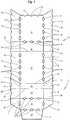
- Packages of this typeconsist of a box part 10 and a lid 11. These main parts of the pack are made of a one-piece blank ( Fig. 1 ) educated. Furthermore, the folding box on a presently formed from a separate blank collar 12. The entirety of such packages includes a preferably block-shaped package contents, namely a group of cigarettes enveloped by an inner blank 48 of tinfoil, paper or the like. This unit forms a block-shaped cigarette block 49. Furthermore, the finished package can be surrounded by an outer cut of foil (not shown).
- the blankcomprises by default by longitudinal fold lines 13 and transverse fold lines 14 limited folding flaps or packing walls.
- the box part 10are areas of the blank for a box front wall 15, an adjoining bottom wall 16, a box rear wall 17 and box front wall 15 attached (outer) box side flaps 18 and inner box connected to the box rear wall 17 Box side tabs 19 assigned. The latter are provided adjacent to the bottom wall 16 with bottom corner tabs 20.
- the side flaps 18, 19each form box side walls 21 together.
- the bottom corner flaps 20are folded so that they rest against the inside of the bottom wall 16.
- the lid 11is formed, namely consists of the lid front wall 22, end wall 23 and lid rear wall 24. The latter is connected via a transverse line joint 25 with the box rear wall 17. Laterally on the lid front wall 22 (outer) lid side tabs 26 are attached. These include inner lid side tabs 27 in the region of the lid rear wall 24. At the - trapezoidal - lid side tabs 27 of the lid rear wall 24 end corner flaps 28 are arranged. Furthermore, the lid 11 includes a lid inner tab 29. This is in the finished package folded against the inside of the lid front wall 22 and connected thereto. The lid side tabs 26, 27 are in the finished package together and are connected by gluing. It thus creates the lid side walls 30th
- the packages which are typical in the structure, in the present case collapsible boxes,are provided in the region of upright or transversely directed packing edges and / or in the region of selected surfaces of the packing walls with special functional structures which convey positive sensations to the consumer when holding and / or operating the pack.
- the invention in the embodiment of Fig. 1 to Fig. 4 in the region of selected Lijnsfaltlinien 13 and / or Querfaltlinien 14 holes 31are attached, which at the same time as the production of the blank ( Fig. 1 ) are produced by punching.
- the holes 31here have a special shape, namely are formed substantially elliptical with tapered, rounded end portions, so that a total of approximately lenticular holes 31 are formed, which are arranged centrally of the fold lines 13, 14.
- a series of a plurality of holes 31is arranged, preferably at equal distances from one another.
- An embodiment in which the sections of the longitudinal fold lines 13 assigned to the front side of the carton part 10 have, for example, four holes 31is advantageous.
- the folded edges of the box rear wall 17 associated regions of the fold lines 13have, for example, five holes 31 due to greater length.
- the transverse fold line 14 on the front side of the bottom wall 16is provided with a plurality of, for example, three holes 31.
- a hole 31In the area of the cover 11 are holes 31 in the front fold lines 13, in this case a hole 31.
- three holes 31are provided.
- Rear transverse fold lines 14 of the bottom wall 16 and the end wall 23 and the longitudinal fold line 13 of the lid rear wall 24remain without holes.
- the holes 31form corresponding recesses or a wavy contour in the region of the upright (in cross-section at right angles) packing edges.
- the double-layer formation of the box side walls 21 and the lid side walls 30becomes thereby takes into account that the folding tabs 18, 19, 27, 28 have recesses or edge recesses 32 which complement each other in the folding position or correspond with holes 31 in the region of associated (rear) folding edges, so that the structure with depressions of the package edges also forms on the rear side.
- the trough-shaped depressions due to the holes 31are on the inside partially covered by the cigarette block 49, partly by the collar 12.
- a special featureis the design of the lid 11 in the front area.
- the transverse edge 14 between the lid front wall 22 and end wall 23is provided with preferably three, distributed to the longitudinal center plane recesses provided due to corresponding holes 31.
- front side packing edges 13 of the lid 11is one, preferably approximately centrally disposed recess due to a hole 31 provided. Thereby, the lid 11 can be effectively detected when opening in this area.
- the transverse edge 14 between the lid front wall 22 and lid inner tabs 29 - in the present case provided with three evenly spaced holes 31 -forms a lid-closing edge 33 due to the folded position of the lid inner flap 29, the closed lid 11 a box closing edge 34 as upper Limitation of the box front wall 15 opposite.
- Lid-closing edge 33 and box closing edge 34form by interaction of holes 31 and edge recesses 32 has a special structure.
- the holes 31 of the lid 11 in the region of the lid closing edge 33lead due to the folded position to the formation of rounded, marginal punched out.
- the box closing edge 34is presently also provided with three edge recesses 32 which are aligned with the holes 31 of the lid closing edge 33.
- the openings 35are arranged in a special formation, namely a star-like.
- a central, central opening 35is preferably formed with a larger diameter (3 mm to 8 mm, in particular 5 mm or 6 mm) than a plurality of preferably smaller openings 36 (2 mm to 5 mm, in particular 3) arranged along radial (imaginary) lines mm).
- the openings 35, 36 in the particular formationform a decorative enhancement of the package, in particular when, as shown, the openings 35, 36 are covered on the inside by the collar 12 enlarged in the region of a front wall, the collar 12 or its front wall being colored can be specially designed.
- the holes 35, 36form a structure field 50 due to their arrangement and size, which facilitates the gripping and holding of the package, in particular when opening and closing the lid 11.
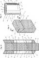
- the embodiment according to FIGS. 7 to 9is concerned with a three-dimensional structure of packing walls, in this case the lid front wall 22.
- Thisis provided with a number of preferably formed smaller holes, namely pin holes 37.
- pin holes 37are in the Packungswandung arranged so that in the area of the holes 37, an outwardly directed material deformation is formed, namely a bulge or the needle hole 37 surrounding, projecting edge 38.
- the pinholes 37are here arranged in parallel transverse rows with a total trapezoidal shape of the formation, the also serves as a functional structure field 50.
- This structural panel 50is preferably located approximately in the center of the lid front wall 22 as a handle panel with significantly increased friction for manually grasping the lid 11 in the region of the lid front wall 22.
- the lid inner tab 29can cover the needle holes 37 inside (partially).
- the uniform, grid-like deformations 39, 40are significant, for example with a depth of deformation (in the region of the mold edges 40) of about 1/10 mm to 5/10 mm, preferably in the order of 2/10 mm to 3/10 mm. Also, the size of the fields (scales) is preferably limited to dimensions (edge lengths) of 2 mm to 5 mm in each direction for functional reasons.
- all the walls of the packageare provided with the small-keyed structure (scale imprinting) except for inner box side flaps 19 and inner lid side flaps 27. These are each provided with adhesive for connection to the outer side flaps 18, 26 Furthermore, the bottom corner tabs 20 and the top corner tabs 28 are free of imprints.
- the lid inner tab 29is provided with a (flake) embossing, which corresponds to the shape of the lid front wall 22 when the lid inner flap 29 is folded.
- the collar 12is also formed with a flat (scale) embossment that is otherwise suitable for the package.
- FIGS. 13 to 15A special feature with regard to the applied structure is shown in the exemplary embodiment FIGS. 13 to 15 , Selected surfaces or walls of the folding box, in this case the lid front wall 22 is provided with projections or elevations, present in the form of individual, relatively small knobs 41, which consist of a separate material and applied to the relevant surface of the package and associated with this.
- the knobs 41form a structure field 50, which in the present case extends over the entire cover front wall 22.
- the knobs 41may be made of plastic, wherein the material is applied in a flowable or moldable state, preferably in the manufacture of the blank ( Fig. 13 ). By curing the material, the dimensionally stable, associated with the packing wall knobs 41. These may preferably consist of a hot melt glue, that is, a substance which is moldable at higher temperatures and at the usual ambient temperature during use of the pack is fixed.
- the knobs 41have a round or dome-like structure and are preferably arranged in transverse rows, in any case in a narrow structure on the surface of the lid front wall 22 (or other packing wall).
- FIG. 16shows an alternative to the above embodiment.
- a packing wall -presently an area of the lid front wall 22 facing the end wall 23 of the lid 11, in this case outside the lid inner flap 29 - has, as a structure field 50, preferably rounded depressions 42 formed by embossing the material of the blank.
- An originally formable substanceis filled into these depressions thus created, which preferably terminates flush with the outside of the lid front wall 22 and thus forms a filling 43 of the depressions 42.
- the material of the fillings 43has an increased coefficient of friction, consists in particular of plastic or hotmelt substance.
- the embossments or depressions 42 and their filling 43are preferably used in the production of the blank (FIG. Fig. 13 ) produced.
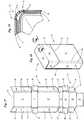
- a design example of a folding boxis shown with specially designed packing edges. It is a so-called round-edge packing, in which upright packing edges are formed as round edges 44, preferably with the cross-sectional shape of a quarter circle.
- the cut( Fig. 17 ) contains in the region of the round edges 44 no single fold lines produced by embossing, but a group of punctiform embossments, which are formed to an embossing strip 45 corresponding to the dimension of the circular edge 44.
- Each embossing strip 45consists of a plurality of small, point-shaped elevations, which - analogous to the embodiment of Fig. 9 - Are formed as sting holes 46.
- Corresponding needle-shaped toolsare - preferably in the manufacture of the blank according to Fig. 17 - Effective on the inside of the blank, so that through holes 46 arise with tapered ridges 47 on the outside of the pack.
- embossing strips 45 thus formedare arranged in the region of all rounded packing edges 44, here also in the region of the lid 11. This structure, preferably exclusively in the area of the curves, gives the consumer a secure feeling when holding the package. Even with smooth surfaces of the pack, moreover, this can be kept without increased pressure.
- the embodiments described abovecan, if appropriate, be used together in packages.
- the design of the lid front wall 22 in the embodiment according to FIGS. 7 to 9 or in the execution according to FIGS. 13 to 16can be advantageous in packs according to Fig. 5, Fig. 6 or according to Fig. 17 to Fig. 19 be used.
- Full-surface structures accordingly 10 to FIG. 12can be used for individual selected packing walls.
- the special training of the round edges 44 in 17 to 19can be used analogously for octagonal or beveled packs.
- all shown and described structures for other (cigarette) packsmay find application, especially in packages of the type shell and slide, cup packs or so-called cap boxes.
Landscapes
- Engineering & Computer Science (AREA)
- Mechanical Engineering (AREA)
- Packaging Of Annular Or Rod-Shaped Articles, Wearing Apparel, Cassettes, Or The Like (AREA)
- Cartons (AREA)
Description
Translated fromGermanDie Erfindung betrifft eine Zigarettenpackung in der Ausführung als Klappschachtel mit den weiteren Merkmalen des Oberbegriffs des Anspruchs 1.The invention relates to a cigarette pack in the embodiment as a folding box with the further features of the preamble of claim 1.
Zigarettenpackungen des vorgenannten Typs aus dünnem Karton sind üblicherweise mit durchgehenden, im Querschnitt rechtwinkligen Kanten ausgebildet. Bei einer aus Kunststoff bestehenden Packung gemäß
Die der Erfindung zugrundeliegende Aufgabe besteht darin, die Handhabung von standardmäßig ausgebildeten Klappschachteln aus dünnem Karton zu verbessern.The problem underlying the invention is to improve the handling of standard designed folding boxes made of thin cardboard.
Zur Lösung dieser Aufgabe ist die erfindungsgemäße Packung mit den Merkmalen des Patentanspruchs 1 ausgebildet.To solve this problem, the package according to the invention with the features of claim 1 is formed.
Durch die gemäß Anspruch 1 ausgebildeten Packungskanten kann die Packung leichter von Hand erfasst werden. Weiterhin ist durch die gezielte Anordnung von Ausnehmungen bzw. Löchern im Bereich des Deckels das Öffnen und Schließen der Packung erleichtert. Weitere Einzelheiten und Merkmale der erfindungsgemäßen Packung werden nachfolgend anhand der Zeichnungen näher erläutert, wobei die erfindungsgemäße Packung in
- Fig. 1
- einen ausgebreiteten Zuschnitt für eine Packung des Typs Klappschachtel,
- Fig. 2
- eine aus einem Zuschnitt gemäß
Fig. 1 gefertigte erfindungsgemäße Klappschachtel in perspektivischer Frontansicht, - Fig. 3
- die Packung gemäß
Fig. 2 in perspektivischer Rückansicht, - Fig. 4
- die Packung gemäß
Fig. 2, Fig. 3 bei geöffnetem Deckel, ebenfalls in perspektivischer Darstellung, - Fig.5
- einen ausgebreiteten Zuschnitt für eine Klappschachtel einer anderen Ausführung,
- Fig. 6
- eine Packung aus einem Zuschnitt gemäß
Fig. 5 in perspektivischer Darstellung, - Fig. 7
- einen Zuschnitt für eine andere Ausführung einer Klappschachtel,
- Fig. 8
- eine Packung aus einem Zuschnitt der
Fig. 7 in perspektivischer Darstellung, - Fig. 9
- einen Teilschnitt in vertikaler Schnittebene IX-IX der
Fig. 8 in vergrößertem Maßstab, - Fig. 10
- einen weiteren Zuschnitt für eine Klappschachtel,
- Fig. 11
- eine Packung aus einem Zuschnitt gemäß
Fig. 10 in perspektivischer Darstellung, - Fig. 12
- einen vertikalen Teilschnitt XII-XII der Packung gemäß
Fig. 11 in vergrößertem Maßstab, - Fig. 13
- einen Zuschnitt für eine weitere Ausführung einer Klappschachtel,
- Fig. 14
- eine fertige Packung aus einem Zuschnitt gemäß
Fig. 13 in perspektivischer Darstellung, - Fig. 15
- einen vertikalen Teilschnitt XV-XV der Packung gemäß
Fig. 14 in vergrößertem Maßstab, - Fig. 16
- eine Darstellung analog
Fig. 15 für ein weiteres Ausführungsbeispiel, - Fig. 17
- einen Zuschnitt für eine Rundkanten-Packung,
- Fig. 18
- eine Packung aus einem Zuschnitt gemäß
Fig. 17 in perspektivischer Darstellung, - Fig. 19
- einen horizontalen Teil-Querschnitt XIX-XIV der
Fig. 18 in vergrößertem Maßstab.
- Fig. 1
- an unfolded blank for a pack of the folding box type,
- Fig. 2
- one from a blank according to
Fig. 1 fabricated folding box according to the invention in a perspective front view, - Fig. 3
- the pack according to
Fig. 2 in perspective rear view, - Fig. 4
- the pack according to
Fig. 2, Fig. 3 with lid open, also in perspective view, - Figure 5
- a spread blank for a folding box of another embodiment,
- Fig. 6
- a pack from a blank according to
Fig. 5 in perspective, - Fig. 7
- a blank for another embodiment of a folding box,
- Fig. 8
- a pack from a blank of
Fig. 7 in perspective, - Fig. 9
- a partial section in the vertical sectional plane IX-IX of
Fig. 8 on an enlarged scale, - Fig. 10
- another blank for a folding box,
- Fig. 11
- a pack from a blank according to
Fig. 10 in perspective, - Fig. 12
- a vertical partial section XII-XII of the package according to
Fig. 11 on an enlarged scale, - Fig. 13
- a blank for a further embodiment of a folding box,
- Fig. 14
- a finished package from a blank according to
Fig. 13 in perspective, - Fig. 15
- a vertical partial section XV-XV of the package according to
Fig. 14 on an enlarged scale, - Fig. 16
- a representation analog
Fig. 15 for a further embodiment, - Fig. 17
- a blank for a round edge pack,
- Fig. 18
- a pack from a blank according to
Fig. 17 in perspective, - Fig. 19
- a horizontal part-section XIX-XIV of
Fig. 18 on an enlarged scale.
Die besonderen Ausführungsbeispiele von (Zigaretten-)Packungen in den Zeichnungen beziehen sich auf Klappschachteln aus (dünnem) Karton mit einem im Wesentlichen standardmäßigen Aufbau.The particular embodiments of (cigarette) packages in the drawings refer to folding boxes of (thin) cardboard of a substantially standard construction.
Packungen dieses Typs bestehen aus einem Schachtelteil 10 und einem Deckel 11. Diese Hauptteile der Packung sind aus einem einstückigen Zuschnitt (
Der Zuschnitt umfasst standardmäßig durch Längsfaltlinien 13 und Querfaltlinien 14 begrenzte Faltlappen bzw. Packungswände. Dem Schachtelteil 10 sind Bereiche des Zuschnitts für eine Schachtel-Vorderwand 15, eine an diese anschließende Bodenwand 16, eine Schachtel-Rückwand 17 und an der Schachtel-Vorderwand 15 angebrachte (äußere) Schachtel-Seitenlappen 18 sowie mit der Schachtel-Rückwand 17 verbundene innere Schachtel-Seitenlappen 19 zugeordnet. Letztere sind benachbart zur Bodenwand 16 mit Boden-Ecklappen 20 versehen. Bei der fertigen Packung bilden die Seitenlappen 18, 19 jeweils gemeinsam Schachtel-Seitenwände 21. Die Boden-Ecklappen 20 sind so gefaltet, dass sie an der Innenseite der Bodenwand 16 anliegen.The blank comprises by default by
In analoger Weise ist der Deckel 11 ausgebildet, besteht nämlich aus Deckel-Vorderwand 22, Stirnwand 23 und Deckel-Rückwand 24. Letztere ist über ein quergerichtetes Liniengelenk 25 mit der Schachtel-Rückwand 17 verbunden. Seitlich an der Deckel-Vorderwand 22 sind (äußere) Deckel-Seitenlappen 26 angebracht. Hierzu gehören innere Deckel-Seitenlappen 27 im Bereich der Deckel-Rückwand 24. An den - trapezförmigen - Deckel-Seitenlappen 27 der Deckel-Rückwand 24 sind Stirn-Ecklappen 28 angeordnet. Des Weiteren gehört zum Deckel 11 ein Deckel-Innenlappen 29. Dieser ist bei der fertigen Packung gegen die Innenseite der Deckel-Vorderwand 22 gefaltet und mit dieser verbunden. Die Deckel-Seitenlappen 26, 27 liegen bei der fertigen Packung aneinander und sind durch Klebung verbunden. Es entstehen so die Deckel-Seitenwände 30.In an analogous manner, the
Die im Aufbau typischen Packungen, vorliegend Klappschachteln, sind im Bereich von aufrechten bzw. quergerichteten Packungskanten und/oder im Bereich ausgewählter Flächen der Packungswände mit besonderen funktionalen Strukturen versehen, die dem Verbraucher beim Halten und/oder Bedienen der Packung positive Empfindungen vermitteln. Erfindungsgemäß sind bei dem Ausführungsbeispiel der
Bei der fertiggefalteten Packung bilden die Löcher 31 entsprechende Vertiefungen bzw. eine wellenförmige Kontur im Bereich der aufrechten (im Querschnitt rechtwinkligen) Packungskanten. Die doppellagige Ausbildung der Schachtel-Seitenwände 21 und der Deckel-Seitenwände 30 wird dadurch berücksichtigt, dass die Faltlappen 18, 19, 27, 28 Vertiefungen bzw. Randausnehmungen 32 aufweisen, die in Faltstellung einander ergänzen bzw. mit Löchern 31 im Bereich zugeordneter (rückseitiger) Faltkanten korrespondieren, so dass auch rückseitig die Struktur mit Vertiefungen der Packungskanten entsteht. Die muldenförmigen Vertiefungen aufgrund der Löcher 31 sind innenseitig zum Teil durch den Zigarettenblock 49, zum Teil durch den Kragen 12 abgedeckt.In the finished folded pack, the
Im Bereich der Frontseite der Packung sind lediglich die vorderen Querfaltlinien 14 bzw. die daraus gebildeten Faltkanten mit einer durch die Löcher 31 geschaffenen Struktur versehen. Es können die rückseitigen Querkanten in gleicher Weise ausgebildet sein.In the area of the front side of the pack, only the front
Eine Besonderheit ist die Gestaltung des Deckels 11 im Bereich der Frontseite. Die Querkante 14 zwischen Deckel-Vorderwand 22 und Stirnwand 23 ist mit vorzugsweise drei, zur Längsmittelebene verteilt angeordneten Ausnehmungen versehen aufgrund entsprechender Löcher 31. Im Bereich der aufrechten, frontseitigen Packungskanten 13 des Deckels 11 ist jeweils eine, vorzugsweise etwa mittig angeordnete Ausnehmung aufgrund eines Lochs 31 vorgesehen. Dadurch kann der Deckel 11 beim Öffnen in diesem Bereich wirksam erfasst werden.A special feature is the design of the
Die Querkante 14 zwischen Deckel-Vorderwand 22 und Deckel-Innenlappen 29 - vorliegend mit drei gleichmäßig verteilten Löchern 31 versehen - bildet aufgrund der Faltstellung des Deckel-Innenlappens 29 eine Deckel-Schließkante 33, die bei geschlossenem Deckel 11 einer Schachtel-Schließkante 34 als obere Begrenzung der Schachtel-Vorderwand 15 gegenüberliegt. Deckel-Schließkante 33 und Schachtel-Schließkante 34 bilden durch Zusammenwirken von Löchern 31 und Randausnehmungen 32 eine besondere Struktur. Die Löcher 31 des Deckels 11 im Bereich der Deckel-Schließkante 33 führen aufgrund der Faltstellung zur Bildung von gerundeten, randseitigen Ausstanzungen. Die Schachtel-Schließkante 34 ist vorliegend ebenfalls mit drei Randausnehmungen 32 versehen, die auf die Löcher 31 der Deckel-Schließkante 33 ausgerichtet sind. In Schließstellung des Deckels 11 entstehen freie Ausnehmungen bzw. Löcher, die durch die Deckel-Schließkante 33 einerseits und die Schachtel-Schließkante 34 andererseits begrenzt sind. Innenseitig sind diese Ausnehmungen bzw. Löcher durch den Kragen 12, nämlich durch eine in üblicher Weise ausgebildete Kragen-Vorderwand begrenzt bzw. verdeckt. Dieser Effekt ergibt sich auch im Bereich der frontseitigen, aufrechten Packungskanten 13 durch vom Kragen gebildeten aufrechten Kragen-Kanten. Weitere, jedoch nicht erfindungsgemäße Packungsstrukturen werden nachfolgend anhand der
Die Öffnungen 35 sind in einer besonderen Formation angeordnet, nämlich sternartig. Eine mittlere, zentrale Öffnung 35 ist vorzugsweise mit größerem Durchmesser (3 mm bis 8 mm, insbesondere 5 mm oder 6 mm) ausgebildet als eine Mehrzahl von entlang radialer (gedachter) Linien angeordneter vorzugsweise kleinerer Öffnungen 36 (2 mm bis 5 mm, insbesondere 3 mm). Die Öffnungen 35, 36 in der besonderen Formation bilden eine dekorative Aufwertung der Packung, insbesondere, wenn, wie gezeigt, die Öffnungen 35, 36 innenseitig durch den im Bereich einer Vorderwand vergrößerten Kragen 12 abgedeckt sind, wobei der Kragen 12 bzw. dessen Vorderwand farblich besonders gestaltet sein kann. Die Löcher 35, 36 bilden aufgrund ihrer Anordnung und Größe ein Strukturfeld 50, das das Erfassen und Halten der Packung erleichtert, insbesondere beim Öffnen und Schließen des Deckels 11.The
Das Ausführungsbeispiel gemäß
Bei dem Ausführungsbeispiel gemäß
Bei diesem Ausführungsbeispiel sind alle Wandungen bzw. Flächen der Packung mit der kleingerasterten Struktur (Schuppenprägung) versehen, mit Ausnahme von innenliegenden Schachtel-Seitenlappen 19 und innenliegenden Deckel-Seitenlappen 27. Diese sind jeweils mit Kleber versehen zur Verbindung mit den äußeren Seitenlappen 18, 26. Weiterhin sind die Boden-Ecklappen 20 und die Deckel-Ecklappen 28 frei von Prägungen. Hingegen ist der Deckel-Innenlappen 29 mit einer (Schuppen-)Prägung versehen, die bei gefaltetem Deckel-Innenlappen 29 mit der Formgebung der Deckel-Vorderwand 22 korrespondiert.In this embodiment, all the walls of the package are provided with the small-keyed structure (scale imprinting) except for inner box side flaps 19 and inner lid side flaps 27. These are each provided with adhesive for connection to the outer side flaps 18, 26 Furthermore, the
Vorliegend ist auch der Kragen 12 mit einer zu der Packung im Übrigen passenden flächigen (Schuppen-)Prägung ausgebildet.In the present case, the
Eine Besonderheit hinsichtlich der applizierten Struktur zeigt das Ausführungsbeispiel gemäß
Die Noppen 41 können aus Kunststoff bestehen, wobei das Material in fließfähigem bzw. formbarem Zustand aufgebracht wird, vorzugsweise bei der Fertigung des Zuschnitts (
In
Die vorstehend beschriebenen Ausführungsbeispiele können, soweit sinnvoll, bei Packungen gemeinsam verwendet werden. Die Gestaltung der Deckel-Vorderwand 22 in der Ausführung gemäß
Claims (2)
- A cigarette packet in the embodiment of a hinge-lid pack type made of thin cardboard or similar packaging material, having a pack part (10), a lid (11) pivotably connected thereto, and a collar (12) arranged in the pack part, wherein walls of the pack part (10) and of the lid (11) have indentations formed by punchings,characterized by the following features:a) the cigarette packet is formed from a common blank for pack part (10) and lid (11), wherein the blank has holes (31) which are applied by means of punching in the region of selected longitudinal fold lines (13) and/or of cross fold lines (14), such that trough-shaped indentations corresponding to the form of the holes (31) are formed in the region of the fold lines (13, 14) of upright or transversely-directed pack edges formed as a result of right-angled folding,b) mutually overlapping fold tabs (18, 19; 27, 28) for the formation of double-layer side walls, that is to say pack side walls (21) and lid side walls (30), have marginal indentations, namely edge recesses (32), which correspond to holes in the region of associated fold lines,c) a lid front wall (22) forms a lid closing edge (33) by means of a lid inner tab (29) being folded against the inner side of the lid front wall (22),d) arranged in the region of the lid closing edge (33) is a plurality of holes (31) formed by punching which form recesses in the region of the lid closing edge (33) when the lid inner tab (29) is folded,e) a pack closing edge (34) of a pack front wall (15), which lies opposite the lid closing edge (33) when the lid (11) is closed, is provided with open edge recesses (32) formed by punchings,f) the recesses of the lid closing edge (33) and the edge recesses (32) of the pack closing edge (34) opposite thereto form common openings when the lid (11) is closed.
- The packet as claimed in Claim 1,characterized in that all front-side longitudinal fold lines (13) and cross fold lines (14) as well as rear-side longitudinal fold lines (13) are provided with holes (31) in the region of the pack part (10).
Priority Applications (1)
| Application Number | Priority Date | Filing Date | Title |
|---|---|---|---|
| PL12787359TPL2773576T3 (en) | 2011-11-01 | 2012-10-25 | Cigarette package comprising a hinged lid |
Applications Claiming Priority (2)
| Application Number | Priority Date | Filing Date | Title |
|---|---|---|---|
| DE102011117302ADE102011117302A1 (en) | 2011-11-01 | 2011-11-01 | Pack, in particular cigarette pack |
| PCT/EP2012/004452WO2013064224A1 (en) | 2011-11-01 | 2012-10-25 | Package, in particular a cigarette package, with punching or embossing |
Publications (2)
| Publication Number | Publication Date |
|---|---|
| EP2773576A1 EP2773576A1 (en) | 2014-09-10 |
| EP2773576B1true EP2773576B1 (en) | 2017-05-31 |
Family
ID=47189866
Family Applications (1)
| Application Number | Title | Priority Date | Filing Date |
|---|---|---|---|
| EP12787359.4ANot-in-forceEP2773576B1 (en) | 2011-11-01 | 2012-10-25 | Cigarette package comprising a hinged lid |
Country Status (8)
| Country | Link |
|---|---|
| EP (1) | EP2773576B1 (en) |
| JP (1) | JP2014532594A (en) |
| CN (1) | CN103974884A (en) |
| DE (1) | DE102011117302A1 (en) |
| IN (1) | IN2014CN04059A (en) |
| PL (1) | PL2773576T3 (en) |
| RU (1) | RU2607969C2 (en) |
| WO (1) | WO2013064224A1 (en) |
Families Citing this family (3)
| Publication number | Priority date | Publication date | Assignee | Title |
|---|---|---|---|---|
| DE202013100595U1 (en)* | 2013-02-08 | 2013-02-19 | Mayr-Melnhof Karton Ag | Blank and resulting three-dimensional structure |
| EP3240738B1 (en)* | 2014-12-31 | 2020-04-22 | Philip Morris Products S.a.s. | Container with hidden feature |
| JPWO2022102012A1 (en)* | 2020-11-11 | 2022-05-19 |
Family Cites Families (36)
| Publication number | Priority date | Publication date | Assignee | Title |
|---|---|---|---|---|
| US288870A (en)* | 1883-11-20 | schmidt | ||
| DE1293077U (en)* | ||||
| DE658385C (en)* | 1938-03-30 | Martin Brinkmann Akt Ges | Packet of cigarettes | |
| GB288870A (en)* | 1927-07-27 | 1928-04-19 | William Vincent Waite | Improvements in and relating to cartons for holding cigarettes, maches and the like |
| GB630723A (en)* | 1947-05-22 | 1949-10-19 | Cissie Mabel Nicholls | Improvements in cartons, boxes, or like containers |
| BE512469A (en)* | 1951-06-28 | |||
| US2751135A (en)* | 1953-05-27 | 1956-06-19 | Kessler Milton | Frictionally engaged slide box |
| JPS6396335U (en)* | 1986-12-12 | 1988-06-22 | ||
| DE3727489A1 (en)* | 1987-08-18 | 1989-03-02 | Focke & Co | FOLDING BOX FOR CIGARETTES |
| JPH02300532A (en)* | 1989-05-15 | 1990-12-12 | Nissin Kogyo Kk | Friction pad and its manufacturing method |
| JPH068220U (en)* | 1992-07-10 | 1994-02-01 | 花王株式会社 | carton |
| DE19519505A1 (en) | 1995-05-31 | 1996-12-05 | Focke & Co | Hinged box for cigarettes |
| JPH1072028A (en)* | 1996-08-29 | 1998-03-17 | Toppan Printing Co Ltd | Blank sheet for square tubular liquid paper container |
| DE19726324A1 (en) | 1997-06-20 | 1998-12-24 | Focke & Co | Method and device for manufacturing hinged boxes |
| US5924627A (en)* | 1997-08-07 | 1999-07-20 | Philip Morris Incorporated | Packaging blank and container made therefrom |
| ES2201409T3 (en)* | 1998-03-02 | 2004-03-16 | Philip Morris Products S.A. | PACK FOR SMOKING ITEMS .. |
| GB9818357D0 (en)* | 1998-08-21 | 1998-10-14 | Rothmans International Ltd | Pack for smoking articles |
| DE19858786A1 (en)* | 1998-12-10 | 2000-06-15 | Focke & Co | Hinged box for cigarettes |
| TR200101662T2 (en)* | 1998-12-10 | 2001-10-22 | Focke & Co. (Gmbh & Co.) | Folding lid box for cigarette. |
| JP2003276725A (en)* | 2002-03-20 | 2003-10-02 | Dainippon Printing Co Ltd | Paper container |
| DE10219464A1 (en)* | 2002-04-30 | 2003-11-13 | Focke & Co | cigarette pack |
| DE10239681A1 (en)* | 2002-08-26 | 2004-03-11 | Focke Gmbh & Co. Kg | Packet for cigarettes comprises an inner blank having a printed or embossed marking which is found in the region of an opening in the packaging wall and is visible from the outside |
| DE10251743A1 (en)* | 2002-11-05 | 2004-05-13 | Focke Gmbh & Co. Kg | Flip pack especially for cigarettes has longitudinal and transverse edges constructed by forming of packing material as outwards orientated protrusion, round in cross section, or as inwards orientated recess, round in cross section |
| DE20311970U1 (en)* | 2003-07-31 | 2004-02-19 | Henkel Kgaa | Package made from folded cardboard cut-out for pourable goods has at least one wall area with outwardly embossed, three-dimensional surface |
| JP2006304718A (en)* | 2005-04-28 | 2006-11-09 | Banpresto Co Ltd | Cover body of cigarette case |
| US7717261B2 (en)* | 2005-06-10 | 2010-05-18 | Philip Morris Usa Inc. | Hinge lid aroma pack |
| AT503396B1 (en)* | 2006-03-16 | 2008-05-15 | Friedrich Kerber | PROCESS FOR PREPARING A RECESSIBLE COATING |
| RU2384500C1 (en)* | 2006-05-30 | 2010-03-20 | Джапан Тобакко Инк. | Pack for rod-like tobacco goods and stock for this pack |
| US20100059395A1 (en)* | 2008-05-02 | 2010-03-11 | John England | Pack for Smoking Articles |
| GB0808047D0 (en)* | 2008-05-02 | 2008-06-11 | British American Tobacco Co | A pack for smoking articles |
| JP5077563B2 (en)* | 2008-06-06 | 2012-11-21 | 凸版印刷株式会社 | Hinge lid type package |
| WO2010014489A1 (en)* | 2008-08-01 | 2010-02-04 | Meadwestvaco Corporation | Auto-open lid for a multi -product package |
| WO2010017891A1 (en)* | 2008-08-11 | 2010-02-18 | Philip Morris Products S.A. | Container with tactile surface |
| US8607974B2 (en)* | 2008-12-22 | 2013-12-17 | British America Tobacco (Holdings) Limited | Pack for smoking articles |
| EP2325093B1 (en)* | 2009-11-20 | 2012-06-20 | Imperial Tobacco Limited | Package for tobacco-related articles |
| DE102010027140A1 (en)* | 2010-07-14 | 2012-01-19 | British American Tobacco (Germany) Gmbh | Cigarette pack with partially bevelled edges |
- 2011
- 2011-11-01DEDE102011117302Apatent/DE102011117302A1/ennot_activeWithdrawn
- 2012
- 2012-10-25EPEP12787359.4Apatent/EP2773576B1/ennot_activeNot-in-force
- 2012-10-25PLPL12787359Tpatent/PL2773576T3/enunknown
- 2012-10-25WOPCT/EP2012/004452patent/WO2013064224A1/enactiveApplication Filing
- 2012-10-25ININ4059CHN2014patent/IN2014CN04059A/enunknown
- 2012-10-25RURU2014122025Apatent/RU2607969C2/enactive
- 2012-10-25JPJP2014539254Apatent/JP2014532594A/enactivePending
- 2012-10-25CNCN201280060787.XApatent/CN103974884A/enactivePending
Also Published As
| Publication number | Publication date |
|---|---|
| CN103974884A (en) | 2014-08-06 |
| JP2014532594A (en) | 2014-12-08 |
| RU2014122025A (en) | 2015-12-10 |
| IN2014CN04059A (en) | 2015-09-04 |
| DE102011117302A1 (en) | 2013-05-02 |
| RU2607969C2 (en) | 2017-01-11 |
| WO2013064224A1 (en) | 2013-05-10 |
| EP2773576A1 (en) | 2014-09-10 |
| PL2773576T3 (en) | 2017-11-30 |
Similar Documents
| Publication | Publication Date | Title |
|---|---|---|
| EP2029446B1 (en) | Flip-top packet for cigarettes | |
| EP0837012B1 (en) | Hinged-lid cigarette box | |
| EP0745541B1 (en) | Hinged-lid box for cigarettes | |
| EP3284699B1 (en) | Cigarette package | |
| DE3124118C2 (en) | ||
| EP2310300B1 (en) | (cigarette) pack and process and device for producing it | |
| EP3066032B1 (en) | Cigarette pack | |
| EP2593382B1 (en) | Soft pack for cigarettes | |
| EP3003884B1 (en) | Cigarette pack | |
| EP0835827A2 (en) | Parallellepipediccigarette package and its blank | |
| EP3197787B1 (en) | Hinge-lid pack for cigarettes | |
| DE102008013173A1 (en) | Folding box for cigarettes | |
| DE102016012300A1 (en) | Cigarette pack and method and apparatus for making the same | |
| WO2004041677A1 (en) | Hinge-lid packet for cigarettes | |
| EP2773576B1 (en) | Cigarette package comprising a hinged lid | |
| DE69300056T2 (en) | Cigarette packaging with more than one opening option. | |
| DE2844444C2 (en) | Packaging, in particular cuboid cigarette packs, and processes for producing blanks for this packaging | |
| EP2445813B1 (en) | Hinge-lid box for cigarettes | |
| DE60100130T2 (en) | Automated packaging case | |
| DE69200626T2 (en) | Packaging, in particular for bundles of products from the tobacco industry, cutting and manufacturing processes for this packaging. | |
| WO2010034378A1 (en) | Unitary package for cigarettes | |
| DE60219636T2 (en) | FOOD CONTAINERS | |
| DE4236447A1 (en) | Paper-based profile body and method for producing the same | |
| WO2006119947A1 (en) | Cigarette pack and method for the production thereof | |
| EP2064134B1 (en) | Hinge-lid box for cigarettes and blank for hinge-lid boxes |
Legal Events
| Date | Code | Title | Description |
|---|---|---|---|
| PUAI | Public reference made under article 153(3) epc to a published international application that has entered the european phase | Free format text:ORIGINAL CODE: 0009012 | |
| 17P | Request for examination filed | Effective date:20140602 | |
| AK | Designated contracting states | Kind code of ref document:A1 Designated state(s):AL AT BE BG CH CY CZ DE DK EE ES FI FR GB GR HR HU IE IS IT LI LT LU LV MC MK MT NL NO PL PT RO RS SE SI SK SM TR | |
| DAX | Request for extension of the european patent (deleted) | ||
| 17Q | First examination report despatched | Effective date:20151106 | |
| GRAP | Despatch of communication of intention to grant a patent | Free format text:ORIGINAL CODE: EPIDOSNIGR1 | |
| INTG | Intention to grant announced | Effective date:20161223 | |
| GRAS | Grant fee paid | Free format text:ORIGINAL CODE: EPIDOSNIGR3 | |
| GRAA | (expected) grant | Free format text:ORIGINAL CODE: 0009210 | |
| AK | Designated contracting states | Kind code of ref document:B1 Designated state(s):AL AT BE BG CH CY CZ DE DK EE ES FI FR GB GR HR HU IE IS IT LI LT LU LV MC MK MT NL NO PL PT RO RS SE SI SK SM TR | |
| REG | Reference to a national code | Ref country code:CH Ref legal event code:EP Ref country code:GB Ref legal event code:FG4D Free format text:NOT ENGLISH | |
| REG | Reference to a national code | Ref country code:AT Ref legal event code:REF Ref document number:897235 Country of ref document:AT Kind code of ref document:T Effective date:20170615 | |
| REG | Reference to a national code | Ref country code:IE Ref legal event code:FG4D Free format text:LANGUAGE OF EP DOCUMENT: GERMAN | |
| REG | Reference to a national code | Ref country code:DE Ref legal event code:R096 Ref document number:502012010457 Country of ref document:DE | |
| REG | Reference to a national code | Ref country code:NL Ref legal event code:MP Effective date:20170531 | |
| REG | Reference to a national code | Ref country code:LT Ref legal event code:MG4D | |
| PG25 | Lapsed in a contracting state [announced via postgrant information from national office to epo] | Ref country code:ES Free format text:LAPSE BECAUSE OF FAILURE TO SUBMIT A TRANSLATION OF THE DESCRIPTION OR TO PAY THE FEE WITHIN THE PRESCRIBED TIME-LIMIT Effective date:20170531 Ref country code:LT Free format text:LAPSE BECAUSE OF FAILURE TO SUBMIT A TRANSLATION OF THE DESCRIPTION OR TO PAY THE FEE WITHIN THE PRESCRIBED TIME-LIMIT Effective date:20170531 Ref country code:NO Free format text:LAPSE BECAUSE OF FAILURE TO SUBMIT A TRANSLATION OF THE DESCRIPTION OR TO PAY THE FEE WITHIN THE PRESCRIBED TIME-LIMIT Effective date:20170831 Ref country code:HR Free format text:LAPSE BECAUSE OF FAILURE TO SUBMIT A TRANSLATION OF THE DESCRIPTION OR TO PAY THE FEE WITHIN THE PRESCRIBED TIME-LIMIT Effective date:20170531 Ref country code:GR Free format text:LAPSE BECAUSE OF FAILURE TO SUBMIT A TRANSLATION OF THE DESCRIPTION OR TO PAY THE FEE WITHIN THE PRESCRIBED TIME-LIMIT Effective date:20170901 Ref country code:FI Free format text:LAPSE BECAUSE OF FAILURE TO SUBMIT A TRANSLATION OF THE DESCRIPTION OR TO PAY THE FEE WITHIN THE PRESCRIBED TIME-LIMIT Effective date:20170531 | |
| PG25 | Lapsed in a contracting state [announced via postgrant information from national office to epo] | Ref country code:IS Free format text:LAPSE BECAUSE OF FAILURE TO SUBMIT A TRANSLATION OF THE DESCRIPTION OR TO PAY THE FEE WITHIN THE PRESCRIBED TIME-LIMIT Effective date:20170930 Ref country code:SE Free format text:LAPSE BECAUSE OF FAILURE TO SUBMIT A TRANSLATION OF THE DESCRIPTION OR TO PAY THE FEE WITHIN THE PRESCRIBED TIME-LIMIT Effective date:20170531 Ref country code:BG Free format text:LAPSE BECAUSE OF FAILURE TO SUBMIT A TRANSLATION OF THE DESCRIPTION OR TO PAY THE FEE WITHIN THE PRESCRIBED TIME-LIMIT Effective date:20170831 Ref country code:LV Free format text:LAPSE BECAUSE OF FAILURE TO SUBMIT A TRANSLATION OF THE DESCRIPTION OR TO PAY THE FEE WITHIN THE PRESCRIBED TIME-LIMIT Effective date:20170531 Ref country code:RS Free format text:LAPSE BECAUSE OF FAILURE TO SUBMIT A TRANSLATION OF THE DESCRIPTION OR TO PAY THE FEE WITHIN THE PRESCRIBED TIME-LIMIT Effective date:20170531 Ref country code:NL Free format text:LAPSE BECAUSE OF FAILURE TO SUBMIT A TRANSLATION OF THE DESCRIPTION OR TO PAY THE FEE WITHIN THE PRESCRIBED TIME-LIMIT Effective date:20170531 | |
| PG25 | Lapsed in a contracting state [announced via postgrant information from national office to epo] | Ref country code:CZ Free format text:LAPSE BECAUSE OF FAILURE TO SUBMIT A TRANSLATION OF THE DESCRIPTION OR TO PAY THE FEE WITHIN THE PRESCRIBED TIME-LIMIT Effective date:20170531 Ref country code:SK Free format text:LAPSE BECAUSE OF FAILURE TO SUBMIT A TRANSLATION OF THE DESCRIPTION OR TO PAY THE FEE WITHIN THE PRESCRIBED TIME-LIMIT Effective date:20170531 Ref country code:RO Free format text:LAPSE BECAUSE OF FAILURE TO SUBMIT A TRANSLATION OF THE DESCRIPTION OR TO PAY THE FEE WITHIN THE PRESCRIBED TIME-LIMIT Effective date:20170531 Ref country code:EE Free format text:LAPSE BECAUSE OF FAILURE TO SUBMIT A TRANSLATION OF THE DESCRIPTION OR TO PAY THE FEE WITHIN THE PRESCRIBED TIME-LIMIT Effective date:20170531 Ref country code:DK Free format text:LAPSE BECAUSE OF FAILURE TO SUBMIT A TRANSLATION OF THE DESCRIPTION OR TO PAY THE FEE WITHIN THE PRESCRIBED TIME-LIMIT Effective date:20170531 | |
| PG25 | Lapsed in a contracting state [announced via postgrant information from national office to epo] | Ref country code:SM Free format text:LAPSE BECAUSE OF FAILURE TO SUBMIT A TRANSLATION OF THE DESCRIPTION OR TO PAY THE FEE WITHIN THE PRESCRIBED TIME-LIMIT Effective date:20170531 | |
| REG | Reference to a national code | Ref country code:DE Ref legal event code:R097 Ref document number:502012010457 Country of ref document:DE | |
| PLBE | No opposition filed within time limit | Free format text:ORIGINAL CODE: 0009261 | |
| STAA | Information on the status of an ep patent application or granted ep patent | Free format text:STATUS: NO OPPOSITION FILED WITHIN TIME LIMIT | |
| 26N | No opposition filed | Effective date:20180301 | |
| PG25 | Lapsed in a contracting state [announced via postgrant information from national office to epo] | Ref country code:SI Free format text:LAPSE BECAUSE OF FAILURE TO SUBMIT A TRANSLATION OF THE DESCRIPTION OR TO PAY THE FEE WITHIN THE PRESCRIBED TIME-LIMIT Effective date:20170531 Ref country code:MC Free format text:LAPSE BECAUSE OF FAILURE TO SUBMIT A TRANSLATION OF THE DESCRIPTION OR TO PAY THE FEE WITHIN THE PRESCRIBED TIME-LIMIT Effective date:20170531 | |
| REG | Reference to a national code | Ref country code:CH Ref legal event code:PL | |
| GBPC | Gb: european patent ceased through non-payment of renewal fee | Effective date:20171025 | |
| REG | Reference to a national code | Ref country code:IE Ref legal event code:MM4A | |
| REG | Reference to a national code | Ref country code:FR Ref legal event code:ST Effective date:20180629 | |
| PG25 | Lapsed in a contracting state [announced via postgrant information from national office to epo] | Ref country code:LU Free format text:LAPSE BECAUSE OF NON-PAYMENT OF DUE FEES Effective date:20171025 Ref country code:LI Free format text:LAPSE BECAUSE OF NON-PAYMENT OF DUE FEES Effective date:20171031 Ref country code:GB Free format text:LAPSE BECAUSE OF NON-PAYMENT OF DUE FEES Effective date:20171025 Ref country code:CH Free format text:LAPSE BECAUSE OF NON-PAYMENT OF DUE FEES Effective date:20171031 | |
| REG | Reference to a national code | Ref country code:BE Ref legal event code:MM Effective date:20171031 | |
| PG25 | Lapsed in a contracting state [announced via postgrant information from national office to epo] | Ref country code:FR Free format text:LAPSE BECAUSE OF NON-PAYMENT OF DUE FEES Effective date:20171031 Ref country code:BE Free format text:LAPSE BECAUSE OF NON-PAYMENT OF DUE FEES Effective date:20171031 | |
| PG25 | Lapsed in a contracting state [announced via postgrant information from national office to epo] | Ref country code:MT Free format text:LAPSE BECAUSE OF FAILURE TO SUBMIT A TRANSLATION OF THE DESCRIPTION OR TO PAY THE FEE WITHIN THE PRESCRIBED TIME-LIMIT Effective date:20170531 | |
| PG25 | Lapsed in a contracting state [announced via postgrant information from national office to epo] | Ref country code:IE Free format text:LAPSE BECAUSE OF NON-PAYMENT OF DUE FEES Effective date:20171025 | |
| REG | Reference to a national code | Ref country code:AT Ref legal event code:MM01 Ref document number:897235 Country of ref document:AT Kind code of ref document:T Effective date:20171025 | |
| PG25 | Lapsed in a contracting state [announced via postgrant information from national office to epo] | Ref country code:AT Free format text:LAPSE BECAUSE OF NON-PAYMENT OF DUE FEES Effective date:20171025 | |
| PG25 | Lapsed in a contracting state [announced via postgrant information from national office to epo] | Ref country code:HU Free format text:LAPSE BECAUSE OF FAILURE TO SUBMIT A TRANSLATION OF THE DESCRIPTION OR TO PAY THE FEE WITHIN THE PRESCRIBED TIME-LIMIT; INVALID AB INITIO Effective date:20121025 | |
| PG25 | Lapsed in a contracting state [announced via postgrant information from national office to epo] | Ref country code:CY Free format text:LAPSE BECAUSE OF NON-PAYMENT OF DUE FEES Effective date:20170531 | |
| PG25 | Lapsed in a contracting state [announced via postgrant information from national office to epo] | Ref country code:MK Free format text:LAPSE BECAUSE OF FAILURE TO SUBMIT A TRANSLATION OF THE DESCRIPTION OR TO PAY THE FEE WITHIN THE PRESCRIBED TIME-LIMIT Effective date:20170531 | |
| PG25 | Lapsed in a contracting state [announced via postgrant information from national office to epo] | Ref country code:TR Free format text:LAPSE BECAUSE OF FAILURE TO SUBMIT A TRANSLATION OF THE DESCRIPTION OR TO PAY THE FEE WITHIN THE PRESCRIBED TIME-LIMIT Effective date:20170531 | |
| PG25 | Lapsed in a contracting state [announced via postgrant information from national office to epo] | Ref country code:PT Free format text:LAPSE BECAUSE OF FAILURE TO SUBMIT A TRANSLATION OF THE DESCRIPTION OR TO PAY THE FEE WITHIN THE PRESCRIBED TIME-LIMIT Effective date:20170531 | |
| PG25 | Lapsed in a contracting state [announced via postgrant information from national office to epo] | Ref country code:AL Free format text:LAPSE BECAUSE OF FAILURE TO SUBMIT A TRANSLATION OF THE DESCRIPTION OR TO PAY THE FEE WITHIN THE PRESCRIBED TIME-LIMIT Effective date:20170531 | |
| PGFP | Annual fee paid to national office [announced via postgrant information from national office to epo] | Ref country code:PL Payment date:20210917 Year of fee payment:10 | |
| PGFP | Annual fee paid to national office [announced via postgrant information from national office to epo] | Ref country code:DE Payment date:20210929 Year of fee payment:10 | |
| PGFP | Annual fee paid to national office [announced via postgrant information from national office to epo] | Ref country code:IT Payment date:20220927 Year of fee payment:11 | |
| REG | Reference to a national code | Ref country code:DE Ref legal event code:R119 Ref document number:502012010457 Country of ref document:DE | |
| P01 | Opt-out of the competence of the unified patent court (upc) registered | Effective date:20230517 | |
| PG25 | Lapsed in a contracting state [announced via postgrant information from national office to epo] | Ref country code:DE Free format text:LAPSE BECAUSE OF NON-PAYMENT OF DUE FEES Effective date:20230503 | |
| PG25 | Lapsed in a contracting state [announced via postgrant information from national office to epo] | Ref country code:PL Free format text:LAPSE BECAUSE OF NON-PAYMENT OF DUE FEES Effective date:20221025 | |
| PG25 | Lapsed in a contracting state [announced via postgrant information from national office to epo] | Ref country code:IT Free format text:LAPSE BECAUSE OF NON-PAYMENT OF DUE FEES Effective date:20231025 | |
| PG25 | Lapsed in a contracting state [announced via postgrant information from national office to epo] | Ref country code:IT Free format text:LAPSE BECAUSE OF NON-PAYMENT OF DUE FEES Effective date:20231025 |