EP2772213A1 - Surgical instrument end effector articulation drive with pinion and opposing racks - Google Patents
Surgical instrument end effector articulation drive with pinion and opposing racksDownload PDFInfo
- Publication number
- EP2772213A1 EP2772213A1EP14157346.9AEP14157346AEP2772213A1EP 2772213 A1EP2772213 A1EP 2772213A1EP 14157346 AEP14157346 AEP 14157346AEP 2772213 A1EP2772213 A1EP 2772213A1
- Authority
- EP
- European Patent Office
- Prior art keywords
- cam
- cam gear
- end effector
- lock bar
- teeth
- Prior art date
- Legal status (The legal status is an assumption and is not a legal conclusion. Google has not performed a legal analysis and makes no representation as to the accuracy of the status listed.)
- Granted
Links
- 239000012636effectorSubstances0.000titleclaimsabstractdescription140
- 230000033001locomotionEffects0.000claimsabstractdescription30
- 238000004891communicationMethods0.000claimsabstractdescription26
- 238000000034methodMethods0.000claimsdescription18
- 230000000295complement effectEffects0.000claimsdescription2
- 238000010304firingMethods0.000description62
- 230000004044responseEffects0.000description10
- 239000000463materialSubstances0.000description9
- 239000010410layerSubstances0.000description8
- 230000007246mechanismEffects0.000description7
- 238000012986modificationMethods0.000description4
- 230000004048modificationEffects0.000description4
- 210000000056organAnatomy0.000description4
- 230000005855radiationEffects0.000description4
- 230000009471actionEffects0.000description3
- 238000004140cleaningMethods0.000description3
- 230000014509gene expressionEffects0.000description3
- 238000003780insertionMethods0.000description3
- 230000037431insertionEffects0.000description3
- 230000000007visual effectEffects0.000description3
- 230000004913activationEffects0.000description2
- 238000013459approachMethods0.000description2
- 238000001356surgical procedureMethods0.000description2
- 210000000115thoracic cavityAnatomy0.000description2
- 230000007704transitionEffects0.000description2
- 238000013519translationMethods0.000description2
- 238000011282treatmentMethods0.000description2
- 238000002604ultrasonographyMethods0.000description2
- 241000894006BacteriaSpecies0.000description1
- IAYPIBMASNFSPL-UHFFFAOYSA-NEthylene oxideChemical compoundC1CO1IAYPIBMASNFSPL-UHFFFAOYSA-N0.000description1
- 239000004775TyvekSubstances0.000description1
- 229920000690TyvekPolymers0.000description1
- 210000001015abdomenAnatomy0.000description1
- 230000001154acute effectEffects0.000description1
- 230000006978adaptationEffects0.000description1
- 239000000853adhesiveSubstances0.000description1
- 230000001070adhesive effectEffects0.000description1
- 238000004873anchoringMethods0.000description1
- 238000005452bendingMethods0.000description1
- 230000008901benefitEffects0.000description1
- 230000005540biological transmissionEffects0.000description1
- 230000015572biosynthetic processEffects0.000description1
- 230000000740bleeding effectEffects0.000description1
- 210000004204blood vesselAnatomy0.000description1
- 210000001124body fluidAnatomy0.000description1
- 238000012790confirmationMethods0.000description1
- 230000008878couplingEffects0.000description1
- 238000010168coupling processMethods0.000description1
- 238000005859coupling reactionMethods0.000description1
- 239000003814drugSubstances0.000description1
- 229940079593drugDrugs0.000description1
- 238000002651drug therapyMethods0.000description1
- 230000006870functionEffects0.000description1
- 210000001035gastrointestinal tractAnatomy0.000description1
- 238000001415gene therapyMethods0.000description1
- 238000009434installationMethods0.000description1
- 230000003993interactionEffects0.000description1
- 238000002955isolationMethods0.000description1
- 210000004072lungAnatomy0.000description1
- 238000002324minimally invasive surgeryMethods0.000description1
- 230000007935neutral effectEffects0.000description1
- 230000002980postoperative effectEffects0.000description1
- 230000002265preventionEffects0.000description1
- 230000008569processEffects0.000description1
- 238000011084recoveryMethods0.000description1
- 230000035945sensitivityEffects0.000description1
- 239000002356single layerSubstances0.000description1
- 230000001954sterilising effectEffects0.000description1
- 238000004659sterilization and disinfectionMethods0.000description1
- 230000001360synchronised effectEffects0.000description1
- 230000001225therapeutic effectEffects0.000description1
- 210000001835visceraAnatomy0.000description1
- 230000003245working effectEffects0.000description1
- 210000000707wristAnatomy0.000description1
Images


Classifications
- A—HUMAN NECESSITIES
- A61—MEDICAL OR VETERINARY SCIENCE; HYGIENE
- A61B—DIAGNOSIS; SURGERY; IDENTIFICATION
- A61B17/00—Surgical instruments, devices or methods
- A61B17/068—Surgical staplers, e.g. containing multiple staples or clamps
- A61B17/072—Surgical staplers, e.g. containing multiple staples or clamps for applying a row of staples in a single action, e.g. the staples being applied simultaneously
- A61B17/07207—Surgical staplers, e.g. containing multiple staples or clamps for applying a row of staples in a single action, e.g. the staples being applied simultaneously the staples being applied sequentially
- A—HUMAN NECESSITIES
- A61—MEDICAL OR VETERINARY SCIENCE; HYGIENE
- A61B—DIAGNOSIS; SURGERY; IDENTIFICATION
- A61B17/00—Surgical instruments, devices or methods
- A61B17/00234—Surgical instruments, devices or methods for minimally invasive surgery
- A61B2017/00292—Surgical instruments, devices or methods for minimally invasive surgery mounted on or guided by flexible, e.g. catheter-like, means
- A61B2017/003—Steerable
- A61B2017/00318—Steering mechanisms
- A—HUMAN NECESSITIES
- A61—MEDICAL OR VETERINARY SCIENCE; HYGIENE
- A61B—DIAGNOSIS; SURGERY; IDENTIFICATION
- A61B17/00—Surgical instruments, devices or methods
- A61B2017/00367—Details of actuation of instruments, e.g. relations between pushing buttons, or the like, and activation of the tool, working tip, or the like
- A61B2017/00389—Button or wheel for performing multiple functions, e.g. rotation of shaft and end effector
- A—HUMAN NECESSITIES
- A61—MEDICAL OR VETERINARY SCIENCE; HYGIENE
- A61B—DIAGNOSIS; SURGERY; IDENTIFICATION
- A61B17/00—Surgical instruments, devices or methods
- A61B17/28—Surgical forceps
- A61B17/29—Forceps for use in minimally invasive surgery
- A61B2017/2926—Details of heads or jaws
- A61B2017/2927—Details of heads or jaws the angular position of the head being adjustable with respect to the shaft
- A—HUMAN NECESSITIES
- A61—MEDICAL OR VETERINARY SCIENCE; HYGIENE
- A61B—DIAGNOSIS; SURGERY; IDENTIFICATION
- A61B17/00—Surgical instruments, devices or methods
- A61B17/28—Surgical forceps
- A61B17/29—Forceps for use in minimally invasive surgery
- A61B2017/2946—Locking means
Definitions
- endoscopic surgical instrumentsmay be preferred over traditional open surgical devices since a smaller incision may reduce the post-operative recovery time and complications. Consequently, some endoscopic surgical instruments may be suitable for placement of a distal end effector at a desired surgical site through the cannula of a trocar. These distal end effectors may engage tissue in a number of ways to achieve a diagnostic or therapeutic effect (e.g., endocutter, grasper, cutter, stapler, clip applier, access device, drug/gene therapy delivery device, and energy delivery device using ultrasound, RF, laser, etc.). Endoscopic surgical instruments may include a shaft between the end effector and a handle portion, which is manipulated by the clinician.
- Such a shaftmay enable insertion to a desired depth and rotation about the longitudinal axis of the shaft, thereby facilitating positioning of the end effector within the patient. Positioning of an end effector may be further facilitated through inclusion of one or more articulation joints or features, enabling the end effector to be selectively articulated or otherwise deflected relative to the longitudinal axis of the shaft.
- endoscopic surgical instrumentsinclude surgical staplers. Some such staplers are operable to clamp down on layers of tissue, cut through the clamped layers of tissue, and drive staples through the layers of tissue to substantially seal the severed layers of tissue together near the severed ends of the tissue layers.
- surgical staplersare disclosed in U.S. Pat. No. 4,805,823 , entitled “Pocket Configuration for Internal Organ Staplers,” issued February 21, 1989; U.S. Pat. No. 5,415,334 , entitled “Surgical Stapler and Staple Cartridge,” issued May 16, 1995; U.S. Pat. No. 5,465,895 , entitled “Surgical Stapler Instrument,” issued November 14, 1995; U.S. Pat. No.
- surgical staplers referred to aboveare described as being used in endoscopic procedures, it should be understood that such surgical staplers may also be used in open procedures and/or other non-endoscopic procedures.
- a surgical staplermay be inserted through a thoracotomy and thereby between a patient's ribs to reach one or more organs in a thoracic surgical procedure that does not use a trocar as a conduit for the stapler.
- Such proceduresmay include the use of the stapler to sever and close a vessel leading to a lung. For instance, the vessels leading to an organ may be severed and closed by a stapler before removal of the organ from the thoracic cavity.
- surgical staplersmay be used in various other settings and procedures.
- FIGS. 1-7depict an exemplary surgical stapling and severing instrument (10) that is sized for insertion, in a nonarticulated state as depicted in FIG. 1 , through a trocar cannula to a surgical site in a patient for performing a surgical procedure.
- a trocarmay be inserted in a patient's abdomen, between two of the patient's ribs, or elsewhere.
- instrument (10)is used without a trocar.
- instrument (10)may be inserted directly through a thoracotomy or other type of incision.
- Instrument (10) of the present exampleincludes a handle portion (20) connected to a shaft (22).
- Shaft (22)distally terminates in an articulation joint (11), which is further coupled with an end effector (12).
- end effector (12)is distal with respect to the more proximal handle portion (20).
- spatial termssuch as “vertical” and “horizontal” are used herein with respect to the drawings. However, surgical instruments are used in many orientations and positions, and these terms are not intended to be limiting and absolute.
- shaft (22)is constructed in accordance with at least some of the teachings of U.S. Pat. App. No. [Attorney Docket Number END7181USNP.0599180], entitled “Surgical Instrument with Multi-Diameter Shaft,” filed on even date herewith, the disclosure of which is incorporated by reference herein.
- Other suitable configurations for shaft (22)will be apparent to those of ordinary skill in the art in view of the teachings herein.
- articulation joint (11)may be remotely articulated, as depicted in phantom in FIG. 1 , by an articulation control (13), such that end effector (12) may be deflected from the longitudinal axis (LA) of shaft (22) at a desired angle ( ⁇ ). End effector (12) may thereby reach behind an organ or approach tissue from a desired angle or for other reasons.
- articulation joint (11)enables deflection of end effector (12) along a single plane.
- articulation joint (11)enables deflection of end effector along more than one plane.
- Articulation joint (11) and articulation control (13)may be configured in accordance with the teachings of any of the numerous references that are cited herein.
- articulation joint (11) and/or articulation control (13)may have any other suitable configuration.
- articulation control (13)may instead be configured as a knob that rotates about an axis that is perpendicular to the longitudinal axis (LA) of shaft (22).
- Articulation joint (11)may also be constructed and operable in accordance with at least some of the teachings of U.S. Pat. App. No. [Attorney Docket Number END7181USNP.0599180], the disclosure of which is incorporated by reference herein.
- Other suitable forms that articulation joint (11) and articulation control (13) may takewill be apparent to those of ordinary skill in the art in view of the teachings herein.
- End effector (12) of the present exampleincludes a lower jaw (16) and a pivotable anvil (18).
- lower jaw (16)is constructed in accordance with at least some of the teachings of U.S. Pat. App. No. [Attorney Docket Number END7182USNP.0599227], entitled “Installation Features for Surgical Instrument End Effector Cartridge,” filed on even date herewith, the disclosure of which is incorporated by reference herein.
- Anvil (18)may be constructed in accordance with at least some of the teachings of U.S. Pat. App. No.
- Handle portion (20)includes a pistol grip (24) and a closure trigger (26).
- Closure trigger (26)is pivotable toward pistol grip (24) to cause clamping, or closing, of the anvil (18) toward lower jaw (16) of end effector (12).
- Such closing of anvil (18)is provided through a closure tube (32) and a closure ring (33), which both longitudinally translate relative to handle portion (20) in response to pivoting of closure trigger (26) relative to pistol grip (24).
- Closure tube (32)extends along the length of shaft (22); and closure ring (33) is positioned distal to articulation joint (11).
- Articulation joint (11)is operable to communicate/transmit longitudinal movement from closure tube (32) to closure ring (33).
- Handle portion (20)also includes a firing trigger (28).
- An elongate member (136)(shown in FIG. 11 ) longitudinally extends through shaft (22) and communicates a longitudinal firing motion from handle portion (20) to a firing beam (14) in response to actuation of firing trigger (28).
- This distal translation of firing beam (14)causes the stapling and severing of clamped tissue in end effector (12), as will be described in greater detail below. Thereafter, triggers (26, 28) may be released to release the tissue from end effector (12).
- FIGS. 3-6depict end effector (12) employing an E-beam form of firing beam (14) to perform a number of functions.
- Firing beam (14)may take any other suitable form, including but not limited to non-E-beam forms.
- firing beam (14)includes a transversely oriented upper pin (38), a firing beam cap (44), a transversely oriented middle pin (46), and a distally presented cutting edge (48).
- Upper pin (38)is positioned and translatable within a longitudinal anvil slot (42) of anvil (18).
- Firing beam cap (44)slidably engages a lower surface of lower jaw (16) by having firing beam (14) extend through lower jaw slot (45) (shown in FIG. 4B ) that is formed through lower jaw (16).
- Middle pin (46)slidingly engages a top surface of lower jaw (16), cooperating with firing beam cap (44). Thereby, firing beam (14) affirmatively spaces end effector (12) during firing.
- firing beam (14)may lack upper pin (38), middle pin (46) and/or firing beam cap (44).
- instrument (10)may simply rely on closure ring (33) or some other feature to pivot anvil (18) to a closed position and hold anvil (18) in the closed position while firing beam (14) advances to the distal position.
- firing beam (14) and/or associated lockout featuresmay be constructed and operable in accordance with at least some of the teachings of U.S. Pat. App. No. [Attorney Docket Number END7175USNP.0599231], entitled “Lockout Feature for Movable Cutting Member of Surgical Instrument,” filed on even date herewith, the disclosure of which is incorporated by reference herein.
- Other suitable forms that firing beam (14) may takewill be apparent to those of ordinary skill in the art in view of the teachings herein.
- FIG. 3shows firing beam (14) of the present example proximally positioned and anvil (18) pivoted to an open position, allowing an unspent staple cartridge (37) to be removably installed into a channel of lower jaw (16).
- staple cartridge (37) of this exampleincludes a cartridge body (70), which presents an upper deck (72) and is coupled with a lower cartridge tray (74).
- a vertical slot (49)is formed through part of staple cartridge (37).
- three rows of staple apertures (51)are formed through upper deck (72) on one side of vertical slot (49), with another set of three rows of staple apertures (51) being formed through upper deck (72) on the other side of vertical slot (49).
- a wedge sled (41) and a plurality of staple drivers (43)are captured between cartridge body (70) and tray (74), with wedge sled (41) being located proximal to staple drivers (43).
- Wedge sled (41)is movable longitudinally within staple cartridge (37); while staple drivers (43) are movable vertically within staple cartridge (37).
- Staples (47)are also positioned within cartridge body (70), above corresponding staple drivers (43).
- each staple (47)is driven vertically within cartridge body (70) by a staple driver (43) to drive staple (47) out through an associated staple aperture (51).
- wedge sled (41)presents inclined cam surfaces that urge staple drivers (43) upwardly as wedge sled (41) is driven distally through staple cartridge (37).
- staple cartridge (37)is constructed and operable in accordance with at least some of the teachings of U.S. Pat. App. No. [Attorney Docket Number END7176USNP.0599177], the disclosure of which is incorporated by reference herein.
- staple cartridge (37)may be constructed and operable in accordance with at least some of the teachings of U.S. Pat. App. No. [Attorney Docket Number END7182USNP.0599227], the disclosure of which is incorporated by reference herein.
- Other suitable forms that staple cartridge (37) may takewill be apparent to those of ordinary skill in the art in view of the teachings herein.
- firing beam (14)is then advanced in engagement with anvil (18) by having upper pin (38) enter longitudinal anvil slot (42).
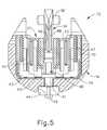
- a pusher block (80)(shown in FIG. 5 ) is located at the distal end of firing beam (14), and is configured to engage wedge sled (41) such that wedge sled (41) is pushed distally by pusher block (80) as firing beam (14) is advanced distally through staple cartridge (37) when firing trigger (28) is actuated.
- FIGS. 4A-4Bdepicts firing beam (14) fully distally translated after completing severing and stapling of tissue.
- staple forming pockets (53)are intentionally omitted from the view in FIGS. 4A-4B ; but staple forming pockets (53) are shown in FIG. 3 . It should also be understood that anvil (18) is intentionally omitted from the view in FIG. 5 .
- FIG. 7shows end effector (12) having been actuated through a single stroke through tissue (90).
- cutting edge (48)(obscured in FIG. 7 ) has cut through tissue (90), while staple drivers (43) have driven three alternating rows of staples (47) through the tissue (90) on each side of the cut line produced by cutting edge (48).
- Staples (47)are all oriented substantially parallel to the cut line in this example, though it should be understood that staples (47) may be positioned at any suitable orientations.
- end effector (12)is withdrawn from the trocar after the first stroke is complete, spent staple cartridge (37) is replaced with a new staple cartridge, and end effector (12) is then again inserted through the trocar to reach the stapling site for further cutting and stapling. This process may be repeated until the desired amount of cuts and staples (47) have been provided.
- Anvil (18)may need to be closed to facilitate insertion and withdrawal through the trocar; and anvil (18) may need to be opened to facilitate replacement of staple cartridge (37).
- cutting edge (48)may sever tissue substantially contemporaneously with staples (47) being driven through tissue during each actuation stroke.
- cutting edge (48)just slightly lags behind driving of staples (47), such that a staple (47) is driven through the tissue just before cutting edge (48) passes through the same region of tissue, though it should be understood that this order may be reversed or that cutting edge (48) may be directly synchronized with adjacent staples.
- FIG. 7shows end effector (12) being actuated in two layers (92, 94) of tissue (90), it should be understood that end effector (12) may be actuated through a single layer of tissue (90) or more than two layers (92, 94) of tissue.
- FIG. 7shows end effector (12) being actuated in two substantially flat, apposed planar layers (92, 94) of tissue, it should be understood that end effector (12) may also be actuated across a tubular structure such as a blood vessel, a section of the gastrointestinal tract, etc.
- FIG. 7should therefore not be viewed as demonstrating any limitation on the contemplated uses for end effector (12).
- instrument (10)may be used will be apparent to those of ordinary skill in the art in view of the teachings herein.
- instrument (10)may be configured and operable in accordance with any of the teachings of U.S. Pat. No. 4,805,823 ; U.S. Pat. No. 5,415,334 ; U.S. Pat. No. 5,465,895 ; U.S. Pat. No. 5,597,107 ; U.S. Pat. No. 5,632,432 ; U.S. Pat. No. 5,673,840 ; U.S. Pat. No. 5,704,534 ; U.S. Pat. No. 5,814,055 ; U.S. Pat. No. 6,978,921 ; U.S. Pat. No. 7,000,818 ; U.S. Pat. No. 7,143,923 ; U.S.
- instrument (10)provides motorized control of firing beam (14).
- FIGS. 8-11show exemplary components that may be used to provide motorized control of firing beam (14).
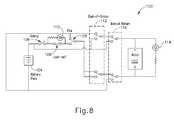
- FIG. 8shows an exemplary control circuit (100) that may be used to power an electric motor (102) with electric power from a battery pack (104) (also shown in FIGS. 1-2 ).
- Electric motor (102)is operable to translate firing beam (14) longitudinally as will be described in greater detail below. It should be understood that the entire control circuit (100), including motor (102) and battery pack (104), may be housed within handle portion (20).
- FIG. 8shows firing trigger (28) as an open switch, though it should be understood that this switch is closed when firing trigger (28) is actuated.
- Circuit (100) of this examplealso includes a safety switch (106) that must be closed in order to complete circuit (100), though it should be understood that safety switch (106) is merely optional. Safety switch (106) may be closed by actuating a separate button, slider, or other feature on handle portion (20).
- Circuit (100) of the present examplealso includes a lockout switch (108), which is configured to be closed by default but is automatically opened in response to a lockout condition.
- a lockout conditionmay include one or more of the following: the absence of a cartridge (37) in lower jaw (16), the presence of a spent (e.g., previously fired) cartridge (37) in lower jaw (16), an insufficiently closed anvil (18), a determination that instrument (10) has been fired too many times, and/or any other suitable conditions.
- a lockout conditionmay include one or more of the following: the absence of a cartridge (37) in lower jaw (16), the presence of a spent (e.g., previously fired) cartridge (37) in lower jaw (16), an insufficiently closed anvil (18), a determination that instrument (10) has been fired too many times, and/or any other suitable conditions.
- lockout switch (108)is opened and thus motor (102) is inoperable when lockout switch (108) is opened.
- a lockout indicator (110)e.g., an LED, etc.
- lockout switch (108), lockout indicator (110), and associated components/functionalitymay be configured in accordance with at least some of the teachings of U.S. Patent No. 7,644,848 , entitled “Electronic Lockouts and Surgical Instrument Including Same,” issued January 12, 2010, the disclosure of which is incorporated by reference herein.
- an end-of-stroke switch (112)is automatically switched to a closed position, reversing the polarity of the voltage applied to motor (102). This reverses the direction of rotation of motor (102), it being understood that the operator will have released firing trigger (28) at this stage of operation.
- current flows through a reverse direction indicator (114)e.g., an LED, etc. to provide a visual indication to the operator that motor (102) rotation has been reversed.
- end-of-stroke switch (112)may be automatically switched to a closed position when firing beam (14) reaches a distal-most position will be apparent to those of ordinary skill in the art in view of the teachings herein.
- reverse direction indicator (114)may take will be apparent to those of ordinary skill in the art in view of the teachings herein.
- Handle portion (20) of the present examplealso includes a manual return switch (116), which is also shown in circuit (100).
- Manual return switch (116)is configured to act as a "bailout” feature, enabling the operator to quickly begin retracting firing beam (14) proximally during a firing stroke.
- manual return switch (116)may be manually actuated when firing beam (14) has only been partially advanced distally.
- Manual return switch (116)may provide functionality similar to end-of-stroke switch (112), reversing the polarity of the voltage applied to motor (102) to thereby reverse the direction of rotation of motor (102). Again, this reversal may be visually indicated through reverse direction indicator (114).
- one or more of switches (28, 106, 108, 112, 116)are in the form of microswitches.
- Other suitable formswill be apparent to those of ordinary skill in the art in view of the teachings herein.
- at least part of circuit (100)may be configured in accordance with at least some of the teachings of U.S. Pat. No. 8,210,411 , entitled “Motor-Driven Surgical Instrument,” issued July 3, 2012, the disclosure of which is incorporated by reference herein.
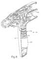
- FIGS. 9-11show various mechanical components that may be used to provide motorized translation of firing beam (14).
- motor (102)housed in pistol grip (24) of handle portion (20).
- battery pack (104)shown in FIGS. 1-2
- Motor (102)has a drive shaft (120) that is coupled with a gear assembly (122).
- Gear assembly (122)has an external casing (not shown) and is operable to drive an upper gear (126), which is shown in FIG. 10 .
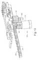
- Upper gear (126)meshes with a pinion (128), which is rotatably supported by a pin (129) secured in handle portion (20). It should therefore be understood that activation of motor (102) will ultimately rotate pinion (128) within handle portion (20).
- a translating rack (130)includes teeth (132) that mesh with pinion (128), such that rack (130) translates longitudinally when pinion (128) rotates.
- rack (130)is coupled with an elongate member (136), which extends through shaft (22) and includes a distal end (138) that couples with the proximal end of firing beam (14).
- Elongate member (136)translates within shaft (22), such that elongate member (136) communicates longitudinal motion of rack (130) to firing beam (14). It should therefore be understood that activation of motor (102) will ultimately translate firing beam (14) within end effector (12).
- motor (102)may drive firing beam (14) distally to sever tissue (90) and drive staples (47) into tissue (90).
- a switch actuation arm (134)extends laterally from rack (130), and is positioned to engage end-of-stroke switch (112) when firing beam (14) reaches a distal-most position (e.g., after tissue (90) has been severed and staples (47) have been driven into tissue (90)).
- this engagement of end-of-stroke switch (112)automatically reverses motor (102) to return firing beam (14) from the distal-most position to the proximal position, enabling anvil (18) to be pivoted away from lower jaw (16) to release tissue (90).
- anvil (18)pivots about an axis that is defined by a pin (or similar feature) that slides along an elongate slot or channel as anvil (18) moves toward lower jaw (16).
- the pivot axistranslates along the path defined by the slot or channel while anvil (18) simultaneously pivots about that axis.
- the pivot axismay slide along the slot/channel first, with anvil (18) then pivoting about the pivot axis after the pivot axis has slid a certain distance along the slot/channel.
- pivotal movementis encompassed within terms such as “pivot,” “pivots,” “pivotal,” “pivotable,” “pivoting,” and the like.
- some versionsmay provide pivotal movement of anvil (18) about an axis that remains fixed and does not translate within a slot or channel, etc.
- the features operable to drive firing beam (14)may be configured in accordance with at least some of the teachings of U.S. Pub. No. 2012/0239012 , the disclosure of which is incorporated by reference herein; and/or in accordance with at least some of the teachings of U.S. Pub. No. 2012/0239012 , the disclosure of which is also incorporated by reference herein.
- Other suitable components, features, and configurations for providing motorization of firing beam (14)will be apparent to those of ordinary skill in the art in view of the teachings herein. It should also be understood that some other versions may provide manual driving of firing beam (14), such that a motor may be omitted.
- firing beam (14)may be actuated in accordance with at least some of the teachings of any other patent/publication reference cited herein.
- instrument (10)As a user urges instrument (10) into a surgical region, it may be desirable to approach the tissue to be clamped, stapled, or cut, from a particular angle. For instance, once end effector (12) of instrument (10) is inserted through a trocar, thoracotomy, or other passageway for entering a surgical area, the tissue that the user wishes to target may be positioned out of reach or at an askew angle in relation to end effector (12) that is aligned with shaft (22). Thus, it may be desirable for portions of instrument (10), such as end effector (12), to articulate such that the user can position anvil (18) and lower jaw (16) of end effector (12) to squarely or perpendicularly clamp against a vessel or other tissue.
- portions of instrument (10)such as end effector (12)
- articulating end effector (12) to squarely position end effector (12) against tissuemay promote full seating and clamping of the tissue prior to cutting and stapling tissue.
- end effector (12)may be selectively locked in a straight or articulated position such that a constant manual bias by the user is not necessary to prevent end effector (12) from pivoting or bending at articulation joint (11). It may also be desirable to automatically lock upon articulation, without requiring actuations of a separate articulation locking feature.
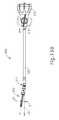
- FIG. 12depicts an exemplary alternative shaft assembly (200) that may be readily incorporated with instrument (10) of FIG. 1 .
- Shaft assembly (200)provides articulation and selective locking of articulation angles, as will be described in greater detail below.
- Shaft assembly (200) of the present examplecomprises a rotation control (213), and articulation knob (214), and an end effector (212).
- Rotation control (213)may be rotatably coupled with handle portion (20) of FIG. 1 or any other suitable component (e.g., robotic control interface, etc.).
- Rotation control (213)is operable to rotate shaft assembly (200) (including articulation knob (214) and end effector (212)) about the longitudinal axis (LA) defined by shaft assembly (200), relative to handle portion (20) (or relative whatever else rotation control (213) is rotatably coupled with). This may be useful in positioning end effector (212) at a desired angular orientation about the longitudinal axis (LA).
- Articulation knob (214)is partially contained within an articulation knob casing (215). Casing (215) leads to an elongate shaft (232). Shaft assembly (200) also comprises an end effector (212) positioned distally in relation to shaft (232). End effector (212) includes an articulation joint (211) which allows end effector (212) to articulate laterally as will be described in further detail below. End effector (212) is substantially identical to end effector (12) of FIG. 1 except as otherwise described below.
- FIGS. 13A-Bshow shaft assembly (200) and an exemplary movement of end effector (212) in response to turning of articulation knob (214).
- FIG. 13Ashows articulation knob (214) in a first position where articulation knob (214) and end effector (212) are both generally aligned along the longitudinal axis (LA) of shaft assembly (200). The user may then manually rotate articulation knob (214) clockwise as seen in FIG. 13B to a second position.
- end effector (212)pivots or bends at articulation joint (211) as seen in FIG. 13B to an articulation angle ( ⁇ ).
- end effector (212)articulates generally in the direction of the rotation of articulation knob (214), though it will be understood that end effector (212) may be configured to bend in the opposite direction of the rotation of articulation knob (214).
- end effector (212)laterally pivots clockwise as shown in FIG. 13B but could be configured in some versions to pivot counter clockwise.
- FIG. 13Bshows end effector (212) laterally pivoting clockwise slightly. It will be understood that articulation knob (214) may be rotated further to cause end effector (212) to laterally articulate further at articulation joint (211) to any suitable angle ( ⁇ ).
- end effector (212)may pivot until an approximately 90° angle is formed across articulation joint (211).
- end effector (212)may be operable to pivot even further such that end effector (212) forms an acute angle in relation to shaft (232).
- Other suitable variations of end effector (212) pivotingwill be apparent to one of ordinary skill in the art in view of the teachings herein.
- articulation knob (214)may define the same angle with the longidunal axis (LA) as the articulation angle ( ⁇ ) defined between end effector (212) and the longidunal axis (LA).
- Such complementary anglingmay provide the operator with visual feedback exterior to the patient, indicating the articulation angle ( ⁇ ) of end effector (212).
- articulation knob (214)may be rotated in the counter clockwise direction to cause end effector (212) to articulate in a counter clockwise manner.
- the usercan simply rotate articulation knob (214) of varying degrees in the direction that the user wishes end effector (212) to articulate to cause varying degrees of articulation of end effector (212).
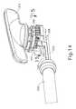
- FIG. 14shows articulation knob (214) with casing (215) removed to better show the inner workings of articulation knob (214).
- Articulation knob (214)is in communication with an articulation pinion (250).
- Articulation pinion (250)is in communication with a first rack (252) and a second rack (256).
- First rack (252)is in communication with a first arm (242) through a first intermediate block (254), whereas second rack (256) is in communication with a second arm (240) through a second intermediate block (256).
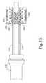
- Articulation knob (214)is unitarily coupled to articulation pinion (250). As a result, when the user turns articulation knob (214), articulation pinion (250) rotates together with articulation knob (214). As articulation pinion (250) rotates, articulation pinion (250) translates first rack (252) and second rack (256) accordingly in opposing directions. For instance, as seen in FIG. 15 , articulation pinion (250) is in communication with first rack (252) and second rack (256) such that if articulation pinion (250) rotates clockwise, first rack (252) retracts proximally away from end effector (212) whereas second rack (256) advances distally toward end effector.
- first rack (252)advances distally toward end effector (212) and second rack (256) retracts proximally away from end effector (212).
- first arm (242)advances and retracts in a similar fashion.
- second rack (256)advances and retracts, second arm (240) also advances and retracts with second rack (256).
- rotating articulation knob (214)which is connected to articulation pinion (250), causes first arm (242) and second arm (240) to move back and forth with first rack (252) and second rack (256). Movement of first arm (242) and second arm (240) is operable to cause movement of other components in end effector (212), which will be discussed in further detail below.
- FIG. 16shows a larger view of end effector (212), including anvil (218).
- First arm (242) and second arm (240)are in communication with a first cam gear (230).
- first cam gear (230)As a result, advancing and retracting first arm (242) and second arm (240) causes first cam gear (230) to rotate, which will be described in further detail below.
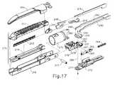
- FIG. 17shows an exploded view of end effector (212) and articulation joint (211).
- End effector (212)comprises an anvil (218), a lower jaw (216), and a staple cartridge (275).
- Cartridge (275)comprises staple drivers (243), a cartridge body (237), a tray (274), and wedge sled (241). It will be appreciated that anvil (218), lower jaw (216), tray (274), cartridge body (237), and wedge sled (241) are substantially similar to anvil (18) lower jaw (16), tray (74), cartridge (37), and wedge sled (41) shown in FIG. 6 .
- tray (274)is removably received in lower jaw (216); and tray (274), cartridge body (237), and staple drivers (243) snap together to form staple cartridge (275).
- the proximal portions of anvil (218) and lower jaw (216)fit within jaw sleeve (270), which is in communication with articulation joint (211).
- Anvil (218)is operable to close against cartridge body (237) in response to distal advancement of jaw sleeve (270), such that anvil (218) and cartridge body (237) can clamp tissue, which may then be stapled and cut.
- wedge sled (241)is driven distally, which urges staple drivers (243) upwardly, which drives staples (not shown, but would otherwise be positioned above staple drivers (243)) through tissue and against anvil (218), anchoring the staples in tissue.
- Sled (241) in the illustrated versionis driven by a knife (248), which is secured to and driven by a firing beam (219). As firing beam (219) advances, knife (248) cuts tissue while driving sled (241).
- End effector (212) of the present examplefurther comprises resilient a lockout feature (249) that is operable to cooperate with cam holding body (276) to selectively restrict advancement of knife (248) in the absence of an unfired cartridge (275) being loaded in lower jaw (216).
- lockout feature (249) and associated componentsmay be configured and operable in accordance with at least some of the teachings of U.S. Pat. App. No. [Attorney Docket Number END7175USNP], entitled “Lockout Feature for Movable Cutting Member of Surgical Instrument,” filed on even date herewith, the disclosure of which is incorporated by reference herein.
- Articulation joint (211)comprises several components that will be discussed in further detail below.
- articulation joint (211)comprises first cam gear (230), second cam gear (231), cam holding body (276), a channel pin (217), joint base (272), a lock bar (262), and a spring (264).
- First arm (242)distally terminates in to a first hook (244), while second arm (240) distally terminates in a second hook (246).
- Hooks (244, 246)are in communication with cam openings (260) of first cam gear (230).
- first cam gear (230)rotates counter clockwise.
- first cam gear (230)rotates clockwise.
- First cam gear (230)is stacked on a second cam gear (231).
- Second cam gear (231) and cam holding pin (279)are unitary features of cam holding body (276).
- second cam gear (231)may be separately constructed and fixedly coupled with cam holding body (276), such that as second cam gear (231) rotates, cam holding body (276) rotates.
- First cam gear (230)is rotationally coupled with cam holding pin (279), which is coaxially aligned with base opening (277) of joint base (272) along a pivot axis (280).
- first cam gear (230)is rotatable about pivot axis (280), relative to second cam gear (231) and cam holding body (276).
- Lock bar (262)is in selective communication with first cam gear (230) and second cam gear (231), which will be described further below. Lock bar (262) is further in communication with spring (264), which distally biases lock bar (262).
- Joint base (272)is shaped to provide a seat and/or channel for lock bar (262) to advance. Lock bar (262) further includes a pair of bosses (287) operable to engage joint base (272) to restrict distal motion of lock bar (262).
- actuating articulation knob (214)is operable to cause opposing advancement and retraction of arms (242, 240). It will be understood that this motion of arms (242, 240) is operable to rotate first cam gear (230) about cam holding pin (279). As a result of rotating first cam gear (230), second cam gear (231) rotates with cam holding body (276). Thus, articulation joint (211) articulates, thereby pivoting end effector (212) at articulation joint (211).
- cam holding pin (279) and base opening (274)define a pivot axis (280), which is generally perpendicular to the longitudinal axis (LA).
- End effector (212)pivots about pivot axis (280) in response to the rotation of first cam gear (230), which drives second cam gear (231) as will be discussed below.
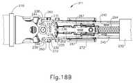
- FIGS. 18A-Eillustrate the details of rotating first cam gear (230) to drive the articulation of end effector (212).
- FIG. 18Ashows articulation joint (211) in a first position.
- Lock bar (262)is distally biased to engage second cam gear (231).
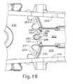
- the distal end of lock bar (262)comprises a lock tooth (236) that fits between first cam teeth (233) and second cam teeth (235) and abuts second cam gear (231), which can be seen in further detail in FIG. 19 .
- lock tooth (236)acts as a positive lock and thus maintains the rotational position of second cam gear (231).
- lock bar (262)maintains the angular position of end effector (212) about pivot axis (280), thereby maintaining any articulation angle ( ⁇ ).
- First cam gear (230)comprises a pair of cam wings (238, 239), and cam holding body (276) comprises a pair of bosses (271, 273).
- Bosses (271, 273)are unitary features of second cam gear (231) such that as bosses (271, 273) rotate, second cam gear (231) also rotates. It will be appreciated that in the first position of FIG. 18A , cam wings (238, 239) and bosses (271, 273) define a small gap (261) therebetween. As a result, cam wings (238, 239) and bosses (271, 273) are not in contact. The interaction involving contact between cam wings (238, 239) and bosses (271, 273) will be described in further detail below with reference to FIGS. 18B-E .
- the usermay guide shaft assembly (200) through a passageway (e.g. trocar, thoracotomy, etc.) to reach the surgical area with end effector (212) in a straightened position as shown in FIG. 18A .
- a passagewaye.g. trocar, thoracotomy, etc.
- FIG. 19shows an enlarged view of lock tooth (236) in the position shown in FIG. 18A .
- lock tooth (236)has generally straight parallel sides (286) that are operable to fit between first cam teeth (233) and second cam teeth (235).
- the distal end of lock tooth (236)has a rounded tip (285) with angled sides (281) leading to parallel sides (286).
- Each tooth (235) of second cam teeth (235)comprises generally straight parallel sides (283) and angled sides (284).
- Parallel sides (283)are operable to engage parallel sides (286) of lock tooth (236) to prevent lock tooth (236) from riding along second cam teeth (235) without assistance from first cam gear (230).
- This engagement between at least one side (283) and at least one side (286)also prevents cam holding body (276) from rotating about pivot axis (280), thereby preventing end effector (212) from pivoting at articulation joint (211).
- first cam gear (230)rotates as shown in FIGS. 18B-C and as will be described in greater detail below, a rounded triangular tooth (233) of first cam gear (230) will cam against angled sides (281), and will thereby drive lock bar (262) proximally in response to first cam (230) rotating.
- tooth (233)may have a variety of different shapes other than triangular.
- Lock tooth (236)moves proximally sufficiently such that angled sides (281) of lock tooth (236) can then eventually engage and ride along angled sides (284) of second cam teeth (235) as first cam gear (230) continues to rotate and as second cam gear (231) rotates. This provides further camming action to drive lock bar (262) proximally.
- lock tooth (236)traverses angled sides (284) of second cam teeth (235), then lock tooth (236) returns distally to a position between the next pair of first cam teeth (233) and second cam teeth (235) similar to the positioning shown in FIG. 19 .
- advancing lock tooth (236) between one set of first cam teeth (233) and second cam teeth (235) to an adjacent set of first cam teeth (233) and second cam teeth (235)may be considered one articulation increment.
- lock tooth (236)strikes second cam gear (231) between second cam teeth (235). It will be understood that lock tooth (236) need not necessarily extend far enough to strike second cam gear (231).
- lock tooth (236)may only extend distally such that parallel sides (283) prevent lock tooth (236) from riding along second cam gear (231) without assistance from first cam teeth (233).
- bosses (287)engage joint base (272) to prevent further distal motion of lock bar (262).
- FIG. 18Bshows a second position for articulation joint (211) to move to in response to turning articulation knob (214) shown in FIG. 14 .
- the userhas turned articulation knob (214) counter clockwise, which rotates articulation pinion (250) counter clockwise as well.
- articulation pinion (250)rotates counter clockwise, first rack (252) moves distally and second rack (256) moves proximally in relation to end effector (212). Accordingly, first arm (242) and second arm (240) as shown in FIG.
- first arm (242)advances toward effector (212) and second arm (240) retracts away from end effector (212).
- distal portions of first arm (242) and second arm (240) of the illustrated versionare not positioned parallel in relation to each other. Instead, first arm (242) and second arm (240) are obliquely angled in relation to each other, though it will be understood that first arm (242) and second arm (240) could be positioned parallel to each other.
- First cam teeth (233)have a rounded triangular shape that urges lock bar (262) proximally away from end effector (212) through a camming action as a result of first cam teeth (233) engaging angled sides (281). Again, teeth (233) may have a variety of different shapes other than triangular.
- Spring (264)compresses to accommodate proximal motion of lock bar (262). As a result, rounded tip (285) moves proximally sufficient to traverse parallel sides (283).
- cam wings (238, 239)rotate counter clockwise with first cam gear (230).
- cam wing (239)removes gap (261) between boss (273) and engages boss (273).
- cam wing (238)moves rotationally away from boss (271).
- first cam gear (230) and lock bar (262)have moved in response to the movement of arms (242, 240) during the transition from the configuration shown in FIG. 18A to the configuration shown in FIG. 18B
- second cam gear (231) and accordingly end effector (212)have not yet moved.
- end effector (212)remains in a straight orientation at this stage.
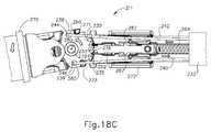
- FIG. 18Cshows a third position of articulation joint (211). It will be understood that the user continues to rotate articulation knob (214) in an effort to articulate end effector (212). Arms (242, 240) continue to move such that first arm (242) moves distally and second arm (240) moves proximally. Movement of arms (242, 240) continues to rotate first cam gear (230), which causes cam wing (239) to rotationally move further thereby urging boss (273) to rotationally move as well. Since boss (273) is unitary with second cam gear (231), second cam gear (231) begins to rotate.
- Second cam gear (231)rotates until tip (288) of second cam gear (231) engages rounded tip (285).
- Second cam teeth (235)have parallel sides (283) such that angled edges (281) of lock tooth (236) can engage angled sides (284) only after first cam teeth (233) urges lock tooth (236) proximally such that rounded tip (285) traverses parallel sides (283).
- lock tooth (236)Prior to riding along first cam teeth (233), lock tooth (236) is generally unable to ride along second cam teeth (235) due to parallel sides (283) engaging parallel sides (286). It will further be appreciated that as lock tooth (236) rides along angled sides (284), lock tooth (236) disengages first cam teeth (233). As also seen in FIG. 18C , lock bar (262) and lock tooth (236) have moved to a proximal most position with just second cam teeth tip (288) being in contact with lock tooth (236). Also as a result of rotation of second cam gear (231), cam holding body (276) and accordingly, sleeve (270), which leads to end effector (212), articulates in a counter clockwise direction.
- FIG. 18Dshows a fourth position for articulation region (211).
- Arms (242, 240)continue to move such that first arm (242) moves distally further and second arm (240) moves proximally further. Movement of arms (242, 240) continues to rotate first cam gear (230), which causes cam wing (239) to push boss (273) rotationally further.
- Lock tooth (236)continues to ride along second cam teeth (235) until the distal bias caused by spring (264) urges lock bar (262) into the position shown in FIG. 18D . It will be appreciated that when lock bar (262) snaps into the position shown in FIG.
- an audible click or snapmay be heard or felt.
- the userreceives audible and/or tactile confirmation that lock tooth (236) has moved from between one set of cam teeth (233, 235) to another or otherwise has rotated by a single articulation increment.
- first cam gear (230)stops rotating and lock tooth (236) fits between cam teeth (233, 235).
- Sleeve (270) and accordingly end effector (212)stop articulating.
- a positive lockhas formed because any rotational motion of second cam gear (231) urged by transverse forces on end effector (212) would result in parallel sides (286) engaging parallel sides (283) and stopping any further rotation of second cam gear (231), which locks the articulation of end effector (212).
- the transition from the configuration shown in FIG. 18A to the configuration shown in FIG. 18Drepresents articulation through one articulation increment, or increment of articulation motion, in which the distance is defined generally by the spaces between second cam teeth (235)
- end effector (212)has articulated thereby providing the user with a shaft assembly (200) with an articulated end effector (212). It will be appreciated that the user may wish to use shaft assembly (200) in the position shown in FIG. 18D or may wish to pivot end effector (212) further by one or more additional articulation increments. In the event that the user does not rotate articulation knob (214) further, the locking of lock tooth (236) between first cam teeth (233) and second cam teeth (235) prevents end effector (212) from pivoting to return to a straight position.
- end effector (212)has been articulated to a desired angle ( ⁇ )
- the usermay actuate firing beam (213) to drive knife (248) to cut and drive staples through tissue.
- knife (248) and firing beam (213)may be in communication through, for instance, a bendable beam such that firing beam (213) can advance through any degree of pivot of articulation joint (211).
- FIG. 18Eshows a fifth position for articulation joint (211) in the event that the user wishes to pivot end effector (212) further.
- usercontinues to rotate articulation knob (214).
- arms (242, 240)continue to move such that first arm (242) moves distally further and second arm (240) moves proximally further.
- Movement of arms (242, 240)continues to rotate first cam gear (230), which causes cam wing (239) to push boss (273) rotationally.
- First cam gear (230) and second cam gear (231)move similarly as shown in FIGS. 18B-D , which causes end effector (212) to articulate further as well as lock in a more articulated position.
- end effector (212)may pivot as far as the user desires. Furthermore, the user may rotate articulation knob (214) in the opposite direction to cause arms (242, 240) and cam gears (230, 231) to move in the opposite direction, thereby causing end effector (212) to articulate in an opposite direction.
- first cam gear (230)is operable to unlock articulation joint (211) and pivot end effector (212) at articulation joint (211) about pivot axis (280), by transferring motion from arms (242, 240) to first cam gear (230).
- second cam gear (231) and lock bar (262)cooperate to lock articulation joint (211), to thereby lock the angle ( ⁇ ) of end effector (212) relative to the longitudinal axis (LA) of shaft assembly (200).
- 2012/0132450entitled “Shiftable Drive Interface for Robotically-Controlled Surgical Tool,” published May 31, 2012, the disclosure of which is incorporated by reference herein;
- U.S. Pub. No. 2012/0199633entitled “Surgical Stapling Instruments with Cam-Driven Staple Deployment Arrangements,” published August 9, 2012, the disclosure of which is incorporated by reference herein;
- U.S. Pub. No. 2012/0199631entitled “Robotically-Controlled Motorized Surgical End Effector System with Rotary Actuated Closure Systems Having Variable Actuation Speeds,” published August 9, 2012, the disclosure of which is incorporated by reference herein;
- 2012/0138660entitled “Robotically-Controlled Cable-Based Surgical End Effectors,” published June 7, 2012, the disclosure of which is incorporated by reference herein; and/or U.S. Pub. No. 2012/0205421 , entitled “Robotically-Controlled Surgical End Effector System with Rotary Actuated Closure Systems,” published August 16, 2012, the disclosure of which is incorporated by reference herein.
- Versions of the devices described abovemay be designed to be disposed of after a single use, or they can be designed to be used multiple times. Versions may, in either or both cases, be reconditioned for reuse after at least one use. Reconditioning may include any combination of the steps of disassembly of the device, followed by cleaning or replacement of particular pieces, and subsequent reassembly. In particular, some versions of the device may be disassembled, and any number of the particular pieces or parts of the device may be selectively replaced or removed in any combination. Upon cleaning and/or replacement of particular parts, some versions of the device may be reassembled for subsequent use either at a reconditioning facility, or by a user immediately prior to a procedure.
- reconditioning of a devicemay utilize a variety of techniques for disassembly, cleaning/replacement, and reassembly. Use of such techniques, and the resulting reconditioned device, are all within the scope of the present application.
- versions described hereinmay be sterilized before and/or after a procedure.
- the deviceis placed in a closed and sealed container, such as a plastic or TYVEK bag.
- the container and devicemay then be placed in a field of radiation that can penetrate the container, such as gamma radiation, x-rays, or high-energy electrons.
- the radiationmay kill bacteria on the device and in the container.
- the sterilized devicemay then be stored in the sterile container for later use.
- a devicemay also be sterilized using any other technique known in the art, including but not limited to beta or gamma radiation, ethylene oxide, or steam.
Landscapes
- Health & Medical Sciences (AREA)
- Life Sciences & Earth Sciences (AREA)
- Surgery (AREA)
- Heart & Thoracic Surgery (AREA)
- Engineering & Computer Science (AREA)
- Biomedical Technology (AREA)
- Nuclear Medicine, Radiotherapy & Molecular Imaging (AREA)
- Medical Informatics (AREA)
- Molecular Biology (AREA)
- Animal Behavior & Ethology (AREA)
- General Health & Medical Sciences (AREA)
- Public Health (AREA)
- Veterinary Medicine (AREA)
- Surgical Instruments (AREA)
- Transmission Devices (AREA)
Abstract
Description
- In some settings, endoscopic surgical instruments may be preferred over traditional open surgical devices since a smaller incision may reduce the post-operative recovery time and complications. Consequently, some endoscopic surgical instruments may be suitable for placement of a distal end effector at a desired surgical site through the cannula of a trocar. These distal end effectors may engage tissue in a number of ways to achieve a diagnostic or therapeutic effect (e.g., endocutter, grasper, cutter, stapler, clip applier, access device, drug/gene therapy delivery device, and energy delivery device using ultrasound, RF, laser, etc.). Endoscopic surgical instruments may include a shaft between the end effector and a handle portion, which is manipulated by the clinician. Such a shaft may enable insertion to a desired depth and rotation about the longitudinal axis of the shaft, thereby facilitating positioning of the end effector within the patient. Positioning of an end effector may be further facilitated through inclusion of one or more articulation joints or features, enabling the end effector to be selectively articulated or otherwise deflected relative to the longitudinal axis of the shaft.
- Examples of endoscopic surgical instruments include surgical staplers. Some such staplers are operable to clamp down on layers of tissue, cut through the clamped layers of tissue, and drive staples through the layers of tissue to substantially seal the severed layers of tissue together near the severed ends of the tissue layers. Merely exemplary surgical staplers are disclosed in
U.S. Pat. No. 4,805,823 , entitled "Pocket Configuration for Internal Organ Staplers," issued February 21, 1989;U.S. Pat. No. 5,415,334 , entitled "Surgical Stapler and Staple Cartridge," issued May 16, 1995;U.S. Pat. No. 5,465,895 , entitled "Surgical Stapler Instrument," issued November 14, 1995;U.S. Pat. No. 5,597,107 , entitled "Surgical Stapler Instrument," issued January 28, 1997;U.S. Pat. No. 5,632,432 , entitled "Surgical Instrument," issued May 27, 1997;U.S. Pat. No. 5,673,840 , entitled "Surgical Instrument," issued October 7, 1997;U.S. Pat. No. 5,704,534 , entitled "Articulation Assembly for Surgical Instruments," issued January 6, 1998;U.S. Pat. No. 5,814,055 , entitled "Surgical Clamping Mechanism," issued September 29, 1998;U.S. Pat. No. 6,978,921 , entitled "Surgical Stapling Instrument Incorporating an E-Beam Firing Mechanism," issued December 27, 2005;U.S. Pat. No. 7,000,818 , entitled "Surgical Stapling Instrument Having Separate Distinct Closing and Firing Systems," issued February 21, 2006;U.S. Pat. No. 7,143,923 , entitled "Surgical Stapling Instrument Having a Firing Lockout for an Unclosed Anvil," issued December 5, 2006;U.S. Pat. No. 7,303,108 , entitled "Surgical Stapling Instrument Incorporating a Multi-Stroke Firing Mechanism with a Flexible Rack," issued December 4, 2007;U.S. Pat. No. 7,367,485 , entitled "Surgical Stapling Instrument Incorporating a Multistroke Firing Mechanism Having a Rotary Transmission," issued May 6, 2008;U.S. Pat. No. 7,380,695 , entitled "Surgical Stapling Instrument Having a Single Lockout Mechanism for Prevention of Firing," issued June 3, 2008;U.S. Pat. No. 7,380,696 , entitled "Articulating Surgical Stapling Instrument Incorporating a Two-Piece E-Beam Firing Mechanism," issued June 3, 2008;U.S. Pat. No. 7,404,508 , entitled "Surgical Stapling and Cutting Device," issued July 29, 2008;U.S. Pat. No. 7,434,715 , entitled "Surgical Stapling Instrument Having Multistroke Firing with Opening Lockout," issued October 14, 2008;U.S. Pat. No. 7,721,930 , entitled "Disposable Cartridge with Adhesive for Use with a Stapling Device," issued May 25, 2010;U.S. Pub. No. 2010/0264193 , entitled "Surgical Stapling Instrument with An Articulatable End Effector," published October 21, 2010; andU.S. Pub. No. 2012/0239012 , entitled "Motor-Driven Surgical Cutting Instrument with Electric Actuator Directional Control Assembly," published September 20, 2012. The disclosure of each of the above-cited U.S. Patents and U.S. Patent Publications is incorporated by reference herein. - While the surgical staplers referred to above are described as being used in endoscopic procedures, it should be understood that such surgical staplers may also be used in open procedures and/or other non-endoscopic procedures. By way of example only, a surgical stapler may be inserted through a thoracotomy and thereby between a patient's ribs to reach one or more organs in a thoracic surgical procedure that does not use a trocar as a conduit for the stapler. Such procedures may include the use of the stapler to sever and close a vessel leading to a lung. For instance, the vessels leading to an organ may be severed and closed by a stapler before removal of the organ from the thoracic cavity. Of course, surgical staplers may be used in various other settings and procedures.
- While various kinds of surgical stapling instruments and associated components have been made and used, it is believed that no one prior to the inventor(s) has made or used the invention described in the appended claims.
- The accompanying drawings, which are incorporated in and constitute a part of this specification, illustrate embodiments of the invention, and, together with the general description of the invention given above, and the detailed description of the embodiments given below, serve to explain the principles of the present invention.
FIG. 1 depicts a perspective view of an exemplary articulating surgical stapling instrument;FIG. 2 depicts a side elevational view of the instrument ofFIG. 1 ;FIG. 3 depicts a perspective view of an opened end effector of the instrument ofFIG. 1 ;FIG. 4A depicts a side cross-sectional view of the end effector ofFIG. 3 , taken along line 4-4 ofFIG. 3 , with the firing beam in a proximal position;FIG. 4B depicts a side cross-sectional view of the end effector ofFIG. 3 , taken along line 4-4 ofFIG. 3 , with the firing beam in a distal position;FIG. 5 depicts an end cross-sectional view of the end effector ofFIG. 3 , taken along line 5-5 ofFIG. 3 ;FIG. 6 depicts an exploded perspective view of the end effector ofFIG. 3 ;FIG. 7 depicts a perspective view of the end effector ofFIG. 3 , positioned at tissue and having been actuated once in the tissue;FIG. 8 depicts a schematic view of an exemplary control circuit for use in the instrument ofFIG. 1 ;FIG. 9 depicts a perspective view of the handle assembly of the instrument ofFIG. 1 , with a housing half removed;FIG. 10 depicts a perspective view of drive assembly components from the handle assembly ofFIG. 9 ;FIG. 11 depicts a perspective view of an elongate member from the drive assembly ofFIG. 10 ;FIG. 12 depicts a top, perspective view of an exemplary alternative shaft assembly that may be incorporated into the instrument ofFIG. 1 ;FIG. 13A depicts a top, plan view of the shaft assembly ofFIG. 12 with the end effector in a first position;FIG. 13B depicts a top, plan view of the shaft assembly ofFIG. 12 with the end effector in a second articulated position;FIG. 14 depicts a perspective view of the proximal end of the shaft assembly ofFIG. 12 showing the articulation knob and internal kinematic components;FIG. 15 depicts a top cross sectional view of the proximal end of the shaft assembly ofFIG. 12 taken along the line 15-15 ofFIG. 14 ;FIG. 16 depicts a top, plan view of the shaft assembly ofFIG. 12 in a neutral position;FIG. 17 depicts a perspective, exploded view of the end effector and the articulation joint of the shaft assembly ofFIG. 12 ;FIG. 18A depicts a top, partially internal view of the articulation joint of the shaft assembly ofFIG. 12 in a first position;FIG. 18B depicts a top, partially internal view of the articulation joint of the shaft assembly ofFIG. 12 with the first and second arms rotating a first cam gear;FIG. 18C depicts a top, partially internal view of the articulation joint of the shaft assembly ofFIG. 12 with the first and second arms rotating a second cam gear and the first cam gear further;FIG. 18D depicts a top, partially internal view of the articulation joint of the shaft assembly ofFIG. 12 with a lock bar resiliently positioning a lock tooth between teeth of the first cam gear and the second cam gear;FIG. 18E depicts a top, partially internal view of the articulation joint of the shaft assembly ofFIG. 12 with the first and second arms rotating the first cam gear yet even further; andFIG. 19 depicts a plan, enlarged view of the interface of the cam gears and the lock bar of the shaft assembly ofFIG. 12 .- The drawings are not intended to be limiting in any way, and it is contemplated that various embodiments of the invention may be carried out in a variety of other ways, including those not necessarily depicted in the drawings. The accompanying drawings incorporated in and forming a part of the specification illustrate several aspects of the present invention, and together with the description serve to explain the principles of the invention; it being understood, however, that this invention is not limited to the precise arrangements shown.
- The following description of certain examples of the invention should not be used to limit the scope of the present invention. Other examples, features, aspects, embodiments, and advantages of the invention will become apparent to those skilled in the art from the following description, which is by way of illustration, one of the best modes contemplated for carrying out the invention. As will be realized, the invention is capable of other different and obvious aspects, all without departing from the invention. Accordingly, the drawings and descriptions should be regarded as illustrative in nature and not restrictive.
FIGS. 1-7 depict an exemplary surgical stapling and severing instrument (10) that is sized for insertion, in a nonarticulated state as depicted inFIG. 1 , through a trocar cannula to a surgical site in a patient for performing a surgical procedure. By way of example only, such a trocar may be inserted in a patient's abdomen, between two of the patient's ribs, or elsewhere. In some settings, instrument (10) is used without a trocar. For instance, instrument (10) may be inserted directly through a thoracotomy or other type of incision. Instrument (10) of the present example includes a handle portion (20) connected to a shaft (22). Shaft (22) distally terminates in an articulation joint (11), which is further coupled with an end effector (12). It should be understood that terms such as "proximal" and "distal" are used herein with reference to a clinician gripping handle portion (20) of instrument (10). Thus, end effector (12) is distal with respect to the more proximal handle portion (20). It will be further appreciated that for convenience and clarity, spatial terms such as "vertical" and "horizontal" are used herein with respect to the drawings. However, surgical instruments are used in many orientations and positions, and these terms are not intended to be limiting and absolute.- In some versions, shaft (22) is constructed in accordance with at least some of the teachings of U.S. Pat. App. No. [Attorney Docket Number END7181USNP.0599180], entitled "Surgical Instrument with Multi-Diameter Shaft," filed on even date herewith, the disclosure of which is incorporated by reference herein. Other suitable configurations for shaft (22) will be apparent to those of ordinary skill in the art in view of the teachings herein.
- Once articulation joint (11) and end effector (12) are inserted through the cannula passageway of a trocar, articulation joint (11) may be remotely articulated, as depicted in phantom in
FIG. 1 , by an articulation control (13), such that end effector (12) may be deflected from the longitudinal axis (LA) of shaft (22) at a desired angle (α). End effector (12) may thereby reach behind an organ or approach tissue from a desired angle or for other reasons. In some versions, articulation joint (11) enables deflection of end effector (12) along a single plane. In some other versions, articulation joint (11) enables deflection of end effector along more than one plane. Articulation joint (11) and articulation control (13) may be configured in accordance with the teachings of any of the numerous references that are cited herein. Alternatively, articulation joint (11) and/or articulation control (13) may have any other suitable configuration. By way of example only, articulation control (13) may instead be configured as a knob that rotates about an axis that is perpendicular to the longitudinal axis (LA) of shaft (22). - Various exemplary alternative components, configurations, and operabilities of articulation joint (11) and articulation control (13) are described in greater detail below. Articulation joint (11) may also be constructed and operable in accordance with at least some of the teachings of U.S. Pat. App. No. [Attorney Docket Number END7181USNP.0599180], the disclosure of which is incorporated by reference herein. Other suitable forms that articulation joint (11) and articulation control (13) may take will be apparent to those of ordinary skill in the art in view of the teachings herein.
- End effector (12) of the present example includes a lower jaw (16) and a pivotable anvil (18). In some versions, lower jaw (16) is constructed in accordance with at least some of the teachings of U.S. Pat. App. No. [Attorney Docket Number END7182USNP.0599227], entitled "Installation Features for Surgical Instrument End Effector Cartridge," filed on even date herewith, the disclosure of which is incorporated by reference herein. Anvil (18) may be constructed in accordance with at least some of the teachings of U.S. Pat. App. No. [Attorney Docket Number END7176USNP.0599177], entitled "Integrated Tissue Positioning and Jaw Alignment Features for Surgical Stapler," filed on even date herewith, the disclosure of which is incorporated by reference herein; at least some of the teachings of U.S. Pat. App. No. [Attorney Docket Number END7177USNP.0599225], entitled "Jaw Closure Feature for End Effector of Surgical Instrument," filed on even date herewith, the disclosure of which is incorporated by reference herein; and/or at least some of the teachings of U.S. Pat. App. No. [Attorney Docket Number END7180USNP.0599175], entitled "Staple Forming Features for Surgical Stapling Instrument," filed on even date herewith, the disclosure of which is incorporated by reference herein. Other suitable forms that lower jaw (16) and anvil (18) may take will be apparent to those of ordinary skill in the art in view of the teachings herein.
- Handle portion (20) includes a pistol grip (24) and a closure trigger (26). Closure trigger (26) is pivotable toward pistol grip (24) to cause clamping, or closing, of the anvil (18) toward lower jaw (16) of end effector (12). Such closing of anvil (18) is provided through a closure tube (32) and a closure ring (33), which both longitudinally translate relative to handle portion (20) in response to pivoting of closure trigger (26) relative to pistol grip (24). Closure tube (32) extends along the length of shaft (22); and closure ring (33) is positioned distal to articulation joint (11). Articulation joint (11) is operable to communicate/transmit longitudinal movement from closure tube (32) to closure ring (33).
- Handle portion (20) also includes a firing trigger (28). An elongate member (136) (shown in
FIG. 11 ) longitudinally extends through shaft (22) and communicates a longitudinal firing motion from handle portion (20) to a firing beam (14) in response to actuation of firing trigger (28). This distal translation of firing beam (14) causes the stapling and severing of clamped tissue in end effector (12), as will be described in greater detail below. Thereafter, triggers (26, 28) may be released to release the tissue from end effector (12). FIGS. 3-6 depict end effector (12) employing an E-beam form of firing beam (14) to perform a number of functions. It should be understood that an E-beam form is just a merely illustrative example. Firing beam (14) may take any other suitable form, including but not limited to non-E-beam forms. As best seen inFIGS. 4A-4B , firing beam (14) includes a transversely oriented upper pin (38), a firing beam cap (44), a transversely oriented middle pin (46), and a distally presented cutting edge (48). Upper pin (38) is positioned and translatable within a longitudinal anvil slot (42) of anvil (18). Firing beam cap (44) slidably engages a lower surface of lower jaw (16) by having firing beam (14) extend through lower jaw slot (45) (shown inFIG. 4B ) that is formed through lower jaw (16). Middle pin (46) slidingly engages a top surface of lower jaw (16), cooperating with firing beam cap (44). Thereby, firing beam (14) affirmatively spaces end effector (12) during firing.- Some non-E-beam forms of firing beam (14) may lack upper pin (38), middle pin (46) and/or firing beam cap (44). Some such versions of instrument (10) may simply rely on closure ring (33) or some other feature to pivot anvil (18) to a closed position and hold anvil (18) in the closed position while firing beam (14) advances to the distal position. By way of example only, firing beam (14) and/or associated lockout features may be constructed and operable in accordance with at least some of the teachings of U.S. Pat. App. No. [Attorney Docket Number END7175USNP.0599231], entitled "Lockout Feature for Movable Cutting Member of Surgical Instrument," filed on even date herewith, the disclosure of which is incorporated by reference herein. Other suitable forms that firing beam (14) may take will be apparent to those of ordinary skill in the art in view of the teachings herein.
FIG. 3 shows firing beam (14) of the present example proximally positioned and anvil (18) pivoted to an open position, allowing an unspent staple cartridge (37) to be removably installed into a channel of lower jaw (16). As best seen inFIGS. 5-6 , staple cartridge (37) of this example includes a cartridge body (70), which presents an upper deck (72) and is coupled with a lower cartridge tray (74). As best seen inFIG. 3 , a vertical slot (49) is formed through part of staple cartridge (37). As also best seen inFIG. 3 , three rows of staple apertures (51) are formed through upper deck (72) on one side of vertical slot (49), with another set of three rows of staple apertures (51) being formed through upper deck (72) on the other side of vertical slot (49). Of course, any other suitable number of staple rows (e.g., two rows, four rows, any other number) may be provided. Referring back toFIGS. 4A-6 , a wedge sled (41) and a plurality of staple drivers (43) are captured between cartridge body (70) and tray (74), with wedge sled (41) being located proximal to staple drivers (43). Wedge sled (41) is movable longitudinally within staple cartridge (37); while staple drivers (43) are movable vertically within staple cartridge (37). Staples (47) are also positioned within cartridge body (70), above corresponding staple drivers (43). In particular, each staple (47) is driven vertically within cartridge body (70) by a staple driver (43) to drive staple (47) out through an associated staple aperture (51). As best seen inFIGS. 4A-4B and6 , wedge sled (41) presents inclined cam surfaces that urge staple drivers (43) upwardly as wedge sled (41) is driven distally through staple cartridge (37).- In some versions, staple cartridge (37) is constructed and operable in accordance with at least some of the teachings of U.S. Pat. App. No. [Attorney Docket Number END7176USNP.0599177], the disclosure of which is incorporated by reference herein. In addition or in the alternative, staple cartridge (37) may be constructed and operable in accordance with at least some of the teachings of U.S. Pat. App. No. [Attorney Docket Number END7182USNP.0599227], the disclosure of which is incorporated by reference herein. Other suitable forms that staple cartridge (37) may take will be apparent to those of ordinary skill in the art in view of the teachings herein.
- With end effector (12) closed as depicted in
FIGS. 4A-4B by distally advancing closure tube (32) and closure ring (33), firing beam (14) is then advanced in engagement with anvil (18) by having upper pin (38) enter longitudinal anvil slot (42). A pusher block (80) (shown inFIG. 5 ) is located at the distal end of firing beam (14), and is configured to engage wedge sled (41) such that wedge sled (41) is pushed distally by pusher block (80) as firing beam (14) is advanced distally through staple cartridge (37) when firing trigger (28) is actuated. During such firing, cutting edge (48) of firing beam (14) enters vertical slot (49) of staple cartridge (37), severing tissue clamped between staple cartridge (37) and anvil (18). As shown inFIGS. 4A-4B , middle pin (46) and pusher block (80) together actuate staple cartridge (37) by entering into vertical slot (49) within staple cartridge (37), driving wedge sled (41) into upward camming contact with staple drivers (43) that in turn drive staples (47) out through staple apertures (51) and into forming contact with staple forming pockets (53) (shown inFIG. 3 ) on the inner surface of anvil (18).FIG. 4B depicts firing beam (14) fully distally translated after completing severing and stapling of tissue. It should be understood that staple forming pockets (53) are intentionally omitted from the view inFIGS. 4A-4B ; but staple forming pockets (53) are shown inFIG. 3 . It should also be understood that anvil (18) is intentionally omitted from the view inFIG. 5 . FIG. 7 shows end effector (12) having been actuated through a single stroke through tissue (90). As shown, cutting edge (48) (obscured inFIG. 7 ) has cut through tissue (90), while staple drivers (43) have driven three alternating rows of staples (47) through the tissue (90) on each side of the cut line produced by cutting edge (48). Staples (47) are all oriented substantially parallel to the cut line in this example, though it should be understood that staples (47) may be positioned at any suitable orientations. In the present example, end effector (12) is withdrawn from the trocar after the first stroke is complete, spent staple cartridge (37) is replaced with a new staple cartridge, and end effector (12) is then again inserted through the trocar to reach the stapling site for further cutting and stapling. This process may be repeated until the desired amount of cuts and staples (47) have been provided. Anvil (18) may need to be closed to facilitate insertion and withdrawal through the trocar; and anvil (18) may need to be opened to facilitate replacement of staple cartridge (37).- It should be understood that cutting edge (48) may sever tissue substantially contemporaneously with staples (47) being driven through tissue during each actuation stroke. In the present example, cutting edge (48) just slightly lags behind driving of staples (47), such that a staple (47) is driven through the tissue just before cutting edge (48) passes through the same region of tissue, though it should be understood that this order may be reversed or that cutting edge (48) may be directly synchronized with adjacent staples. While
FIG. 7 shows end effector (12) being actuated in two layers (92, 94) of tissue (90), it should be understood that end effector (12) may be actuated through a single layer of tissue (90) or more than two layers (92, 94) of tissue. It should also be understood that the formation and positioning of staples (47) adjacent to the cut line produced by cutting edge (48) may substantially seal the tissue at the cut line, thereby reducing or preventing bleeding and/or leaking of other bodily fluids at the cut line. Furthermore, whileFIG. 7 shows end effector (12) being actuated in two substantially flat, apposed planar layers (92, 94) of tissue, it should be understood that end effector (12) may also be actuated across a tubular structure such as a blood vessel, a section of the gastrointestinal tract, etc.FIG. 7 should therefore not be viewed as demonstrating any limitation on the contemplated uses for end effector (12). Various suitable settings and procedures in which instrument (10) may be used will be apparent to those of ordinary skill in the art in view of the teachings herein. - It should be understood that instrument (10) may be configured and operable in accordance with any of the teachings of
U.S. Pat. No. 4,805,823 ;U.S. Pat. No. 5,415,334 ;U.S. Pat. No. 5,465,895 ;U.S. Pat. No. 5,597,107 ;U.S. Pat. No. 5,632,432 ;U.S. Pat. No. 5,673,840 ;U.S. Pat. No. 5,704,534 ;U.S. Pat. No. 5,814,055 ;U.S. Pat. No. 6,978,921 ;U.S. Pat. No. 7,000,818 ;U.S. Pat. No. 7,143,923 ;U.S. Pat. No. 7,303,108 ;U.S. Pat. No. 7,367,485 ;U.S. Pat. No. 7,380,695 ;U.S. Pat. No. 7,380,696 ;U.S. Pat. No. 7,404,508 ;U.S. Pat. No. 7,434,715 ;U.S. Pat. No. 7,721,930 ;U.S. Pub. No. 2010/0264193 ; and/or2012/0239012 . As noted above, the disclosures of each of those patents and publications are incorporated by reference herein. Additional exemplary modifications that may be provided for instrument (10) will be described in greater detail below. Various suitable ways in which the below teachings may be incorporated into instrument (10) will be apparent to those of ordinary skill in the art. Similarly, various suitable ways in which the below teachings may be combined with various teachings of the patents/publications cited herein will be apparent to those of ordinary skill in the art. It should also be understood that the below teachings are not limited to instrument (10) or devices taught in the patents cited herein. The below teachings may be readily applied to various other kinds of instruments, including instruments that would not be classified as surgical staplers. Various other suitable devices and settings in which the below teachings may be applied will be apparent to those of ordinary skill in the art in view of the teachings herein. - In the present example, instrument (10) provides motorized control of firing beam (14).
FIGS. 8-11 show exemplary components that may be used to provide motorized control of firing beam (14). In particular,FIG. 8 shows an exemplary control circuit (100) that may be used to power an electric motor (102) with electric power from a battery pack (104) (also shown inFIGS. 1-2 ). Electric motor (102) is operable to translate firing beam (14) longitudinally as will be described in greater detail below. It should be understood that the entire control circuit (100), including motor (102) and battery pack (104), may be housed within handle portion (20).FIG. 8 shows firing trigger (28) as an open switch, though it should be understood that this switch is closed when firing trigger (28) is actuated. Circuit (100) of this example also includes a safety switch (106) that must be closed in order to complete circuit (100), though it should be understood that safety switch (106) is merely optional. Safety switch (106) may be closed by actuating a separate button, slider, or other feature on handle portion (20). - Circuit (100) of the present example also includes a lockout switch (108), which is configured to be closed by default but is automatically opened in response to a lockout condition. By way of example only, a lockout condition may include one or more of the following: the absence of a cartridge (37) in lower jaw (16), the presence of a spent (e.g., previously fired) cartridge (37) in lower jaw (16), an insufficiently closed anvil (18), a determination that instrument (10) has been fired too many times, and/or any other suitable conditions. Various sensors, algorithms, and other features that may be used to detect lockout conditions will be apparent to those of ordinary skill in the art in view of the teachings herein. Similarly, other suitable kinds of lockout conditions will be apparent to those of ordinary skill in the art in view of the teachings herein. It should be understood that circuit (100) is opened and thus motor (102) is inoperable when lockout switch (108) is opened. A lockout indicator (110) (e.g., an LED, etc.) is operable to provide a visual indication of the status of lockout switch (108). By way of example only, lockout switch (108), lockout indicator (110), and associated components/functionality may be configured in accordance with at least some of the teachings of
U.S. Patent No. 7,644,848 , entitled "Electronic Lockouts and Surgical Instrument Including Same," issued January 12, 2010, the disclosure of which is incorporated by reference herein. - Once firing beam (14) reaches a distal-most position (e.g., at the end of a cutting stroke), an end-of-stroke switch (112) is automatically switched to a closed position, reversing the polarity of the voltage applied to motor (102). This reverses the direction of rotation of motor (102), it being understood that the operator will have released firing trigger (28) at this stage of operation. In this operational state, current flows through a reverse direction indicator (114) (e.g., an LED, etc.) to provide a visual indication to the operator that motor (102) rotation has been reversed. Various suitable ways in which end-of-stroke switch (112) may be automatically switched to a closed position when firing beam (14) reaches a distal-most position will be apparent to those of ordinary skill in the art in view of the teachings herein. Similarly, various suitable forms that reverse direction indicator (114) may take will be apparent to those of ordinary skill in the art in view of the teachings herein.
- Handle portion (20) of the present example also includes a manual return switch (116), which is also shown in circuit (100). Manual return switch (116) is configured to act as a "bailout" feature, enabling the operator to quickly begin retracting firing beam (14) proximally during a firing stroke. In other words, manual return switch (116) may be manually actuated when firing beam (14) has only been partially advanced distally. Manual return switch (116) may provide functionality similar to end-of-stroke switch (112), reversing the polarity of the voltage applied to motor (102) to thereby reverse the direction of rotation of motor (102). Again, this reversal may be visually indicated through reverse direction indicator (114).
- In some versions, one or more of switches (28, 106, 108, 112, 116) are in the form of microswitches. Other suitable forms will be apparent to those of ordinary skill in the art in view of the teachings herein. In addition to or in lieu of the foregoing, at least part of circuit (100) may be configured in accordance with at least some of the teachings of
U.S. Pat. No. 8,210,411 , entitled "Motor-Driven Surgical Instrument," issued July 3, 2012, the disclosure of which is incorporated by reference herein. FIGS. 9-11 show various mechanical components that may be used to provide motorized translation of firing beam (14). In particular,FIG. 9 shows motor (102) housed in pistol grip (24) of handle portion (20). It should be understood that battery pack (104) (shown inFIGS. 1-2 ) may also be located in pistol grip (24) (e.g., below motor (102)) and/or elsewhere within handle portion (20). Motor (102) has a drive shaft (120) that is coupled with a gear assembly (122). Gear assembly (122) has an external casing (not shown) and is operable to drive an upper gear (126), which is shown inFIG. 10 . Upper gear (126) meshes with a pinion (128), which is rotatably supported by a pin (129) secured in handle portion (20). It should therefore be understood that activation of motor (102) will ultimately rotate pinion (128) within handle portion (20).- As also shown in
FIGS. 9-10 , a translating rack (130) includes teeth (132) that mesh with pinion (128), such that rack (130) translates longitudinally when pinion (128) rotates. As shown inFIG. 11 , rack (130) is coupled with an elongate member (136), which extends through shaft (22) and includes a distal end (138) that couples with the proximal end of firing beam (14). Elongate member (136) translates within shaft (22), such that elongate member (136) communicates longitudinal motion of rack (130) to firing beam (14). It should therefore be understood that activation of motor (102) will ultimately translate firing beam (14) within end effector (12). In particular, motor (102) may drive firing beam (14) distally to sever tissue (90) and drive staples (47) into tissue (90). A switch actuation arm (134) extends laterally from rack (130), and is positioned to engage end-of-stroke switch (112) when firing beam (14) reaches a distal-most position (e.g., after tissue (90) has been severed and staples (47) have been driven into tissue (90)). As noted above, this engagement of end-of-stroke switch (112) automatically reverses motor (102) to return firing beam (14) from the distal-most position to the proximal position, enabling anvil (18) to be pivoted away from lower jaw (16) to release tissue (90). - Use of the term "pivot" (and similar terms with "pivot" as a base) should not be read as necessarily requiring pivotal movement about a fixed axis. In some versions, anvil (18) pivots about an axis that is defined by a pin (or similar feature) that slides along an elongate slot or channel as anvil (18) moves toward lower jaw (16). In such versions, the pivot axis translates along the path defined by the slot or channel while anvil (18) simultaneously pivots about that axis. In addition or in the alternative, the pivot axis may slide along the slot/channel first, with anvil (18) then pivoting about the pivot axis after the pivot axis has slid a certain distance along the slot/channel. It should be understood that such sliding/translating pivotal movement is encompassed within terms such as "pivot," "pivots," "pivotal," "pivotable," "pivoting," and the like. Of course, some versions may provide pivotal movement of anvil (18) about an axis that remains fixed and does not translate within a slot or channel, etc.
- In addition to or in lieu of the foregoing, the features operable to drive firing beam (14) may be configured in accordance with at least some of the teachings of
U.S. Pub. No. 2012/0239012 , the disclosure of which is incorporated by reference herein; and/or in accordance with at least some of the teachings ofU.S. Pub. No. 2012/0239012 , the disclosure of which is also incorporated by reference herein. Other suitable components, features, and configurations for providing motorization of firing beam (14) will be apparent to those of ordinary skill in the art in view of the teachings herein. It should also be understood that some other versions may provide manual driving of firing beam (14), such that a motor may be omitted. By way of example only, firing beam (14) may be actuated in accordance with at least some of the teachings of any other patent/publication reference cited herein. - It will be appreciated that as a user urges instrument (10) into a surgical region, it may be desirable to approach the tissue to be clamped, stapled, or cut, from a particular angle. For instance, once end effector (12) of instrument (10) is inserted through a trocar, thoracotomy, or other passageway for entering a surgical area, the tissue that the user wishes to target may be positioned out of reach or at an askew angle in relation to end effector (12) that is aligned with shaft (22). Thus, it may be desirable for portions of instrument (10), such as end effector (12), to articulate such that the user can position anvil (18) and lower jaw (16) of end effector (12) to squarely or perpendicularly clamp against a vessel or other tissue. It will further be understood that articulating end effector (12) to squarely position end effector (12) against tissue may promote full seating and clamping of the tissue prior to cutting and stapling tissue. In addition to articulating, it may be desirable for end effector (12) to be selectively locked in a straight or articulated position such that a constant manual bias by the user is not necessary to prevent end effector (12) from pivoting or bending at articulation joint (11). It may also be desirable to automatically lock upon articulation, without requiring actuations of a separate articulation locking feature.
FIG. 12 depicts an exemplary alternative shaft assembly (200) that may be readily incorporated with instrument (10) ofFIG. 1 . Shaft assembly (200) provides articulation and selective locking of articulation angles, as will be described in greater detail below. Shaft assembly (200) of the present example comprises a rotation control (213), and articulation knob (214), and an end effector (212). Rotation control (213) may be rotatably coupled with handle portion (20) ofFIG. 1 or any other suitable component (e.g., robotic control interface, etc.). Rotation control (213) is operable to rotate shaft assembly (200) (including articulation knob (214) and end effector (212)) about the longitudinal axis (LA) defined by shaft assembly (200), relative to handle portion (20) (or relative whatever else rotation control (213) is rotatably coupled with). This may be useful in positioning end effector (212) at a desired angular orientation about the longitudinal axis (LA).- Articulation knob (214) is partially contained within an articulation knob casing (215). Casing (215) leads to an elongate shaft (232). Shaft assembly (200) also comprises an end effector (212) positioned distally in relation to shaft (232). End effector (212) includes an articulation joint (211) which allows end effector (212) to articulate laterally as will be described in further detail below. End effector (212) is substantially identical to end effector (12) of
FIG. 1 except as otherwise described below. FIGS. 13A-B show shaft assembly (200) and an exemplary movement of end effector (212) in response to turning of articulation knob (214).FIG. 13A shows articulation knob (214) in a first position where articulation knob (214) and end effector (212) are both generally aligned along the longitudinal axis (LA) of shaft assembly (200). The user may then manually rotate articulation knob (214) clockwise as seen inFIG. 13B to a second position. In response to the rotation of articulation knob (214), end effector (212) pivots or bends at articulation joint (211) as seen inFIG. 13B to an articulation angle (α). In the illustrated version, end effector (212) articulates generally in the direction of the rotation of articulation knob (214), though it will be understood that end effector (212) may be configured to bend in the opposite direction of the rotation of articulation knob (214). In other words, when articulation knob (214) is rotated clockwise, end effector (212) laterally pivots clockwise as shown inFIG. 13B but could be configured in some versions to pivot counter clockwise.FIG. 13B shows end effector (212) laterally pivoting clockwise slightly. It will be understood that articulation knob (214) may be rotated further to cause end effector (212) to laterally articulate further at articulation joint (211) to any suitable angle (α). For instance, end effector (212) may pivot until an approximately 90° angle is formed across articulation joint (211). In some versions, end effector (212) may be operable to pivot even further such that end effector (212) forms an acute angle in relation to shaft (232). Other suitable variations of end effector (212) pivoting will be apparent to one of ordinary skill in the art in view of the teachings herein. It should also be understood that articulation knob (214) may define the same angle with the longidunal axis (LA) as the articulation angle (α) defined between end effector (212) and the longidunal axis (LA). Such complementary angling may provide the operator with visual feedback exterior to the patient, indicating the articulation angle (α) of end effector (212).- The mechanics of the articulation of end effector (212) will be discussed in further detail below. It will be appreciated that articulation knob (214) may be rotated in the counter clockwise direction to cause end effector (212) to articulate in a counter clockwise manner. Thus, depending on the desired direction and/or amount of articulation of end effector (212), the user can simply rotate articulation knob (214) of varying degrees in the direction that the user wishes end effector (212) to articulate to cause varying degrees of articulation of end effector (212).
FIG. 14 shows articulation knob (214) with casing (215) removed to better show the inner workings of articulation knob (214). Articulation knob (214) is in communication with an articulation pinion (250). Articulation pinion (250) is in communication with a first rack (252) and a second rack (256). First rack (252) is in communication with a first arm (242) through a first intermediate block (254), whereas second rack (256) is in communication with a second arm (240) through a second intermediate block (256).- Articulation knob (214) is unitarily coupled to articulation pinion (250). As a result, when the user turns articulation knob (214), articulation pinion (250) rotates together with articulation knob (214). As articulation pinion (250) rotates, articulation pinion (250) translates first rack (252) and second rack (256) accordingly in opposing directions. For instance, as seen in
FIG. 15 , articulation pinion (250) is in communication with first rack (252) and second rack (256) such that if articulation pinion (250) rotates clockwise, first rack (252) retracts proximally away from end effector (212) whereas second rack (256) advances distally toward end effector. Furthermore, when articulation pinion (250) rotates counter-clockwise, first rack (252) advances distally toward end effector (212) and second rack (256) retracts proximally away from end effector (212). As first rack (252) advances and retracts, first arm (242) advances and retracts in a similar fashion. Similarly, as second rack (256) advances and retracts, second arm (240) also advances and retracts with second rack (256). Thus, rotating articulation knob (214), which is connected to articulation pinion (250), causes first arm (242) and second arm (240) to move back and forth with first rack (252) and second rack (256). Movement of first arm (242) and second arm (240) is operable to cause movement of other components in end effector (212), which will be discussed in further detail below. FIG. 16 shows a larger view of end effector (212), including anvil (218). First arm (242) and second arm (240) are in communication with a first cam gear (230). As a result, advancing and retracting first arm (242) and second arm (240) causes first cam gear (230) to rotate, which will be described in further detail below.FIG. 17 shows an exploded view of end effector (212) and articulation joint (211). End effector (212) comprises an anvil (218), a lower jaw (216), and a staple cartridge (275). Cartridge (275) comprises staple drivers (243), a cartridge body (237), a tray (274), and wedge sled (241). It will be appreciated that anvil (218), lower jaw (216), tray (274), cartridge body (237), and wedge sled (241) are substantially similar to anvil (18) lower jaw (16), tray (74), cartridge (37), and wedge sled (41) shown inFIG. 6 . Generally, tray (274) is removably received in lower jaw (216); and tray (274), cartridge body (237), and staple drivers (243) snap together to form staple cartridge (275). The proximal portions of anvil (218) and lower jaw (216) fit within jaw sleeve (270), which is in communication with articulation joint (211). Anvil (218) is operable to close against cartridge body (237) in response to distal advancement of jaw sleeve (270), such that anvil (218) and cartridge body (237) can clamp tissue, which may then be stapled and cut. In particular, after clamping tissue, wedge sled (241) is driven distally, which urges staple drivers (243) upwardly, which drives staples (not shown, but would otherwise be positioned above staple drivers (243)) through tissue and against anvil (218), anchoring the staples in tissue. Sled (241) in the illustrated version is driven by a knife (248), which is secured to and driven by a firing beam (219). As firing beam (219) advances, knife (248) cuts tissue while driving sled (241).- End effector (212) of the present example further comprises resilient a lockout feature (249) that is operable to cooperate with cam holding body (276) to selectively restrict advancement of knife (248) in the absence of an unfired cartridge (275) being loaded in lower jaw (216). By way of example only, lockout feature (249) and associated components may be configured and operable in accordance with at least some of the teachings of U.S. Pat. App. No. [Attorney Docket Number END7175USNP], entitled "Lockout Feature for Movable Cutting Member of Surgical Instrument," filed on even date herewith, the disclosure of which is incorporated by reference herein.
- Articulation joint (211) comprises several components that will be discussed in further detail below. Generally speaking, articulation joint (211) comprises first cam gear (230), second cam gear (231), cam holding body (276), a channel pin (217), joint base (272), a lock bar (262), and a spring (264).
- First arm (242) distally terminates in to a first hook (244), while second arm (240) distally terminates in a second hook (246). Hooks (244, 246) are in communication with cam openings (260) of first cam gear (230). As a result, when first arm (242) advances toward end effector (212) and second arm (240) retracts, first cam gear (230) rotates counter clockwise. When first arm (242) instead retracts and second arm (240) advances toward end effector (212), first cam gear (230) rotates clockwise. Thus, as arms (242, 240) push and pull on cam openings (260) via hooks (244, 246), first cam gear (230) rotates accordingly as just described.
- First cam gear (230) is stacked on a second cam gear (231). Second cam gear (231) and cam holding pin (279) are unitary features of cam holding body (276). In some versions, second cam gear (231) may be separately constructed and fixedly coupled with cam holding body (276), such that as second cam gear (231) rotates, cam holding body (276) rotates. First cam gear (230) is rotationally coupled with cam holding pin (279), which is coaxially aligned with base opening (277) of joint base (272) along a pivot axis (280). Thus, first cam gear (230) is rotatable about pivot axis (280), relative to second cam gear (231) and cam holding body (276). Lock bar (262) is in selective communication with first cam gear (230) and second cam gear (231), which will be described further below. Lock bar (262) is further in communication with spring (264), which distally biases lock bar (262). Joint base (272) is shaped to provide a seat and/or channel for lock bar (262) to advance. Lock bar (262) further includes a pair of bosses (287) operable to engage joint base (272) to restrict distal motion of lock bar (262).
- As discussed above, actuating articulation knob (214) is operable to cause opposing advancement and retraction of arms (242, 240). It will be understood that this motion of arms (242, 240) is operable to rotate first cam gear (230) about cam holding pin (279). As a result of rotating first cam gear (230), second cam gear (231) rotates with cam holding body (276). Thus, articulation joint (211) articulates, thereby pivoting end effector (212) at articulation joint (211). In particular, cam holding pin (279) and base opening (274) define a pivot axis (280), which is generally perpendicular to the longitudinal axis (LA). End effector (212) pivots about pivot axis (280) in response to the rotation of first cam gear (230), which drives second cam gear (231) as will be discussed below.
FIGS. 18A-E illustrate the details of rotating first cam gear (230) to drive the articulation of end effector (212). FIG. 18A shows articulation joint (211) in a first position. Lock bar (262) is distally biased to engage second cam gear (231). In particular, the distal end of lock bar (262) comprises a lock tooth (236) that fits between first cam teeth (233) and second cam teeth (235) and abuts second cam gear (231), which can be seen in further detail inFIG. 19 . As a result of the distal bias provided by spring (264), lock tooth (236) acts as a positive lock and thus maintains the rotational position of second cam gear (231). By maintaining the rotational position of second cam gear (231), lock bar (262) maintains the angular position of end effector (212) about pivot axis (280), thereby maintaining any articulation angle (α). First cam gear (230) comprises a pair of cam wings (238, 239), and cam holding body (276) comprises a pair of bosses (271, 273). Bosses (271, 273) are unitary features of second cam gear (231) such that as bosses (271, 273) rotate, second cam gear (231) also rotates. It will be appreciated that in the first position ofFIG. 18A , cam wings (238, 239) and bosses (271, 273) define a small gap (261) therebetween. As a result, cam wings (238, 239) and bosses (271, 273) are not in contact. The interaction involving contact between cam wings (238, 239) and bosses (271, 273) will be described in further detail below with reference toFIGS. 18B-E . During a surgical operation, the user may guide shaft assembly (200) through a passageway (e.g. trocar, thoracotomy, etc.) to reach the surgical area with end effector (212) in a straightened position as shown inFIG. 18A .FIG. 19 shows an enlarged view of lock tooth (236) in the position shown inFIG. 18A . As can be seen in the illustrated version, lock tooth (236) has generally straight parallel sides (286) that are operable to fit between first cam teeth (233) and second cam teeth (235). The distal end of lock tooth (236) has a rounded tip (285) with angled sides (281) leading to parallel sides (286). Each tooth (235) of second cam teeth (235) comprises generally straight parallel sides (283) and angled sides (284). Parallel sides (283) are operable to engage parallel sides (286) of lock tooth (236) to prevent lock tooth (236) from riding along second cam teeth (235) without assistance from first cam gear (230). This engagement between at least one side (283) and at least one side (286) also prevents cam holding body (276) from rotating about pivot axis (280), thereby preventing end effector (212) from pivoting at articulation joint (211).- Once first cam gear (230) rotates as shown in
FIGS. 18B-C and as will be described in greater detail below, a rounded triangular tooth (233) of first cam gear (230) will cam against angled sides (281), and will thereby drive lock bar (262) proximally in response to first cam (230) rotating. It should be understood that tooth (233) may have a variety of different shapes other than triangular. Lock tooth (236) moves proximally sufficiently such that angled sides (281) of lock tooth (236) can then eventually engage and ride along angled sides (284) of second cam teeth (235) as first cam gear (230) continues to rotate and as second cam gear (231) rotates. This provides further camming action to drive lock bar (262) proximally. Once lock tooth (236) traverses angled sides (284) of second cam teeth (235), then lock tooth (236) returns distally to a position between the next pair of first cam teeth (233) and second cam teeth (235) similar to the positioning shown inFIG. 19 . For illustrative purposes, advancing lock tooth (236) between one set of first cam teeth (233) and second cam teeth (235) to an adjacent set of first cam teeth (233) and second cam teeth (235) may be considered one articulation increment. As lock tooth (236) distally advances, lock tooth (236) strikes second cam gear (231) between second cam teeth (235). It will be understood that lock tooth (236) need not necessarily extend far enough to strike second cam gear (231). For instance, lock tooth (236) may only extend distally such that parallel sides (283) prevent lock tooth (236) from riding along second cam gear (231) without assistance from first cam teeth (233). In the illustrated version, bosses (287) engage joint base (272) to prevent further distal motion of lock bar (262). - As noted above, the operator may wish to pivot end effector (212) at articulation joint (211) to better position end effector (212) in relation to targeted tissue.
FIG. 18B shows a second position for articulation joint (211) to move to in response to turning articulation knob (214) shown inFIG. 14 . In the illustrated version, the user has turned articulation knob (214) counter clockwise, which rotates articulation pinion (250) counter clockwise as well. As articulation pinion (250) rotates counter clockwise, first rack (252) moves distally and second rack (256) moves proximally in relation to end effector (212). Accordingly, first arm (242) and second arm (240) as shown inFIG. 18B move such that first arm (242) advances toward effector (212) and second arm (240) retracts away from end effector (212). It will be appreciated that the distal portions of first arm (242) and second arm (240) of the illustrated version are not positioned parallel in relation to each other. Instead, first arm (242) and second arm (240) are obliquely angled in relation to each other, though it will be understood that first arm (242) and second arm (240) could be positioned parallel to each other. - Movement of arms (242, 240) as seen in
FIG. 18B causes first cam gear (230) to rotate counter clockwise about pivot axis (280). As first cam gear (230) rotates, two actions occur in a generally simultaneous manner. First cam teeth (233) have a rounded triangular shape that urges lock bar (262) proximally away from end effector (212) through a camming action as a result of first cam teeth (233) engaging angled sides (281). Again, teeth (233) may have a variety of different shapes other than triangular. Spring (264) compresses to accommodate proximal motion of lock bar (262). As a result, rounded tip (285) moves proximally sufficient to traverse parallel sides (283). Additionally, cam wings (238, 239) rotate counter clockwise with first cam gear (230). As a result of the rotation, cam wing (239) removes gap (261) between boss (273) and engages boss (273). Meanwhile, cam wing (238) moves rotationally away from boss (271). It will be understood that while first cam gear (230) and lock bar (262) have moved in response to the movement of arms (242, 240) during the transition from the configuration shown inFIG. 18A to the configuration shown inFIG. 18B , second cam gear (231) and accordingly end effector (212) have not yet moved. Thus, end effector (212) remains in a straight orientation at this stage. FIG. 18C shows a third position of articulation joint (211). It will be understood that the user continues to rotate articulation knob (214) in an effort to articulate end effector (212). Arms (242, 240) continue to move such that first arm (242) moves distally and second arm (240) moves proximally. Movement of arms (242, 240) continues to rotate first cam gear (230), which causes cam wing (239) to rotationally move further thereby urging boss (273) to rotationally move as well. Since boss (273) is unitary with second cam gear (231), second cam gear (231) begins to rotate. As second cam gear rotates (231), lock bar (262) moves further proximally as a result of angled sides (284) camming against angled sides (281) of lock tooth (236). Thus, lock tooth (236) rides along second cam teeth (235). Second cam gear (231) rotates until tip (288) of second cam gear (231) engages rounded tip (285). Second cam teeth (235) have parallel sides (283) such that angled edges (281) of lock tooth (236) can engage angled sides (284) only after first cam teeth (233) urges lock tooth (236) proximally such that rounded tip (285) traverses parallel sides (283). Prior to riding along first cam teeth (233), lock tooth (236) is generally unable to ride along second cam teeth (235) due to parallel sides (283) engaging parallel sides (286). It will further be appreciated that as lock tooth (236) rides along angled sides (284), lock tooth (236) disengages first cam teeth (233). As also seen inFIG. 18C , lock bar (262) and lock tooth (236) have moved to a proximal most position with just second cam teeth tip (288) being in contact with lock tooth (236). Also as a result of rotation of second cam gear (231), cam holding body (276) and accordingly, sleeve (270), which leads to end effector (212), articulates in a counter clockwise direction.FIG. 18D shows a fourth position for articulation region (211). Once again, it will be understood that user is continuing to rotate articulation knob (214) in an effort to cause further articulation of end effector (212). Arms (242, 240) continue to move such that first arm (242) moves distally further and second arm (240) moves proximally further. Movement of arms (242, 240) continues to rotate first cam gear (230), which causes cam wing (239) to push boss (273) rotationally further. Lock tooth (236) continues to ride along second cam teeth (235) until the distal bias caused by spring (264) urges lock bar (262) into the position shown inFIG. 18D . It will be appreciated that when lock bar (262) snaps into the position shown inFIG. 18D , an audible click or snap may be heard or felt. As a result, the user receives audible and/or tactile confirmation that lock tooth (236) has moved from between one set of cam teeth (233, 235) to another or otherwise has rotated by a single articulation increment. When in the position shown inFIG. 18D , first cam gear (230) stops rotating and lock tooth (236) fits between cam teeth (233, 235). Sleeve (270) and accordingly end effector (212) stop articulating. A positive lock has formed because any rotational motion of second cam gear (231) urged by transverse forces on end effector (212) would result in parallel sides (286) engaging parallel sides (283) and stopping any further rotation of second cam gear (231), which locks the articulation of end effector (212). It should be understood that the transition from the configuration shown inFIG. 18A to the configuration shown inFIG. 18D represents articulation through one articulation increment, or increment of articulation motion, in which the distance is defined generally by the spaces between second cam teeth (235)- It will be understood that in the position shown in
FIG. 18D , end effector (212) has articulated thereby providing the user with a shaft assembly (200) with an articulated end effector (212). It will be appreciated that the user may wish to use shaft assembly (200) in the position shown inFIG. 18D or may wish to pivot end effector (212) further by one or more additional articulation increments. In the event that the user does not rotate articulation knob (214) further, the locking of lock tooth (236) between first cam teeth (233) and second cam teeth (235) prevents end effector (212) from pivoting to return to a straight position. Once end effector (212) has been articulated to a desired angle (α), it will be understood that the user may actuate firing beam (213) to drive knife (248) to cut and drive staples through tissue. For instance, knife (248) and firing beam (213) may be in communication through, for instance, a bendable beam such that firing beam (213) can advance through any degree of pivot of articulation joint (211). FIG. 18E shows a fifth position for articulation joint (211) in the event that the user wishes to pivot end effector (212) further. Once again, it will be understood that user continues to rotate articulation knob (214). As a result, arms (242, 240) continue to move such that first arm (242) moves distally further and second arm (240) moves proximally further. Movement of arms (242, 240) continues to rotate first cam gear (230), which causes cam wing (239) to push boss (273) rotationally. First cam gear (230) and second cam gear (231) move similarly as shown inFIGS. 18B-D , which causes end effector (212) to articulate further as well as lock in a more articulated position. It will be understood that the user may continue to rotate articulation knob (214) to cause end effector (212) to pivot as far as the user desires. Furthermore, the user may rotate articulation knob (214) in the opposite direction to cause arms (242, 240) and cam gears (230, 231) to move in the opposite direction, thereby causing end effector (212) to articulate in an opposite direction.- As seen in the exemplary actuation shown in
FIGS. 18A-18E , first cam gear (230) is operable to unlock articulation joint (211) and pivot end effector (212) at articulation joint (211) about pivot axis (280), by transferring motion from arms (242, 240) to first cam gear (230). In addition, second cam gear (231) and lock bar (262) cooperate to lock articulation joint (211), to thereby lock the angle (α) of end effector (212) relative to the longitudinal axis (LA) of shaft assembly (200). - It should be understood that any one or more of the teachings, expressions, embodiments, examples, etc. described herein may be combined with any one or more of the other teachings, expressions, embodiments, examples, etc. that are described herein. The above-described teachings, expressions, embodiments, examples, etc. should therefore not be viewed in isolation relative to each other. Various suitable ways in which the teachings herein may be combined will be readily apparent to those of ordinary skill in the art in view of the teachings herein. Such modifications and variations are intended to be included within the scope of the claims.
- It should be appreciated that any patent, publication, or other disclosure material, in whole or in part, that is said to be incorporated by reference herein is incorporated herein only to the extent that the incorporated material does not conflict with existing definitions, statements, or other disclosure material set forth in this disclosure. As such, and to the extent necessary, the disclosure as explicitly set forth herein supersedes any conflicting material incorporated herein by reference. Any material, or portion thereof, that is said to be incorporated by reference herein, but which conflicts with existing definitions, statements, or other disclosure material set forth herein will only be incorporated to the extent that no conflict arises between that incorporated material and the existing disclosure material.
- Versions of the devices described above may have application in conventional medical treatments and procedures conducted by a medical professional, as well as application in robotic-assisted medical treatments and procedures. By way of example only, various teachings herein may be readily incorporated into a robotic surgical system such as the DAVINCI™ system by Intuitive Surgical, Inc., of Sunnyvale, California. Similarly, those of ordinary skill in the art will recognize that various teachings herein may be readily combined with various teachings of any of the following:
U.S. Pat. No. 5,792,135 , entitled "Articulated Surgical Instrument For Performing Minimally Invasive Surgery With Enhanced Dexterity and Sensitivity," issued August 11, 1998, the disclosure of which is incorporated by reference herein;U.S. Pat. No. 5,817,084 , entitled "Remote Center Positioning Device with Flexible Drive," issued October 6, 1998, the disclosure of which is incorporated by reference herein;U.S. Pat. No. 5,878,193 , entitled "Automated Endoscope System for Optimal Positioning," issued March 2, 1999, the disclosure of which is incorporated by reference herein;U.S. Pat. No. 6,231,565 , entitled "Robotic Arm DLUS for Performing Surgical Tasks," issued May 15, 2001, the disclosure of which is incorporated by reference herein;U.S. Pat. No. 6,783,524 , entitled "Robotic Surgical Tool with Ultrasound Cauterizing and Cutting Instrument," issued August 31, 2004, the disclosure of which is incorporated by reference herein;U.S. Pat. No. 6,364,888 , entitled "Alignment of Master and Slave in a Minimally Invasive Surgical Apparatus," issued April 2, 2002, the disclosure of which is incorporated by reference herein;U.S. Pat. No. 7,524,320 , entitled "Mechanical Actuator Interface System for Robotic Surgical Tools," issued April 28, 2009, the disclosure of which is incorporated by reference herein;U.S. Pat. No. 7,691,098 , entitled "Platform Link Wrist Mechanism," issued April 6, 2010, the disclosure of which is incorporated by reference herein;U.S. Pat. No. 7,806,891 , entitled "Repositioning and Reorientation of Master/Slave Relationship in Minimally Invasive Telesurgery," issued October 5, 2010, the disclosure of which is incorporated by reference herein;U.S. Pub. No. 2013/0012957 , entitled "Automated End Effector Component Reloading System for Use with a Robotic System, published January 10, 2013, the disclosure of which is incorporated by reference herein;U.S. Pub. No. 2012/0199630 , entitled "Robotically-Controlled Surgical Instrument with Force-Feedback Capabilities," published August 9, 2012, the disclosure of which is incorporated by reference herein;U.S. Pub. No. 2012/0132450 , entitled "Shiftable Drive Interface for Robotically-Controlled Surgical Tool," published May 31, 2012, the disclosure of which is incorporated by reference herein;U.S. Pub. No. 2012/0199633 , entitled "Surgical Stapling Instruments with Cam-Driven Staple Deployment Arrangements," published August 9, 2012, the disclosure of which is incorporated by reference herein;U.S. Pub. No. 2012/0199631 , entitled "Robotically-Controlled Motorized Surgical End Effector System with Rotary Actuated Closure Systems Having Variable Actuation Speeds," published August 9, 2012, the disclosure of which is incorporated by reference herein;U.S. Pub. No. 2012/0199632 , entitled "Robotically-Controlled Surgical Instrument with Selectively Articulatable End Effector," published August 9, 2012, the disclosure of which is incorporated by reference herein;U.S. Pub. No. 2012/0203247 , entitled "Robotically-Controlled Surgical End Effector System," published August 9, 2012, the disclosure of which is incorporated by reference herein;U.S. Pub. No. 2012/0211546 , entitled "Drive Interface for Operably Coupling a Manipulatable Surgical Tool to a Robot," published August 23, 2012;U.S. Pub. No. 2012/0138660 , entitled "Robotically-Controlled Cable-Based Surgical End Effectors," published June 7, 2012, the disclosure of which is incorporated by reference herein; and/orU.S. Pub. No. 2012/0205421 , entitled "Robotically-Controlled Surgical End Effector System with Rotary Actuated Closure Systems," published August 16, 2012, the disclosure of which is incorporated by reference herein. - Versions of the devices described above may be designed to be disposed of after a single use, or they can be designed to be used multiple times. Versions may, in either or both cases, be reconditioned for reuse after at least one use. Reconditioning may include any combination of the steps of disassembly of the device, followed by cleaning or replacement of particular pieces, and subsequent reassembly. In particular, some versions of the device may be disassembled, and any number of the particular pieces or parts of the device may be selectively replaced or removed in any combination. Upon cleaning and/or replacement of particular parts, some versions of the device may be reassembled for subsequent use either at a reconditioning facility, or by a user immediately prior to a procedure. Those skilled in the art will appreciate that reconditioning of a device may utilize a variety of techniques for disassembly, cleaning/replacement, and reassembly. Use of such techniques, and the resulting reconditioned device, are all within the scope of the present application.
- By way of example only, versions described herein may be sterilized before and/or after a procedure. In one sterilization technique, the device is placed in a closed and sealed container, such as a plastic or TYVEK bag. The container and device may then be placed in a field of radiation that can penetrate the container, such as gamma radiation, x-rays, or high-energy electrons. The radiation may kill bacteria on the device and in the container. The sterilized device may then be stored in the sterile container for later use. A device may also be sterilized using any other technique known in the art, including but not limited to beta or gamma radiation, ethylene oxide, or steam.
- Having shown and described various embodiments of the present invention, further adaptations of the methods and systems described herein may be accomplished by appropriate modifications by one of ordinary skill in the art without departing from the scope of the present invention. Several of such potential modifications have been mentioned, and others will be apparent to those skilled in the art. For instance, the examples, embodiments, geometries, materials, dimensions, ratios, steps, and the like discussed above are illustrative and are not required. Accordingly, the scope of the present invention should be considered in terms of the following claims and is understood not to be limited to the details of structure and operation shown and described in the specification and drawings.
Claims (20)
- An apparatus, comprising:(a) a body; and(b) a shaft assembly in communication with the body; wherein the shaft assembly comprises:(i) an end effector having an articulation joint;(ii) a first cam gear rotatably positioned within the shaft assembly,(iii) a second cam gear in communication with the end effector at the articulation joint, and(iv) a lock bar distally biased to lock against the second cam gear, wherein the first cam gear is rotatable through a first range of motion to unlock the lock bar relative to the second cam gear, wherein the first cam gear is rotatable through a second range of motion to rotate the end effector at the articulation joint.
- The apparatus of claim 1, wherein the first cam gear comprises a plurality of cam wings configured to urge rotation of the second cam gear.
- The apparatus of claim 2, wherein the second cam gear comprises a plurality of bosses configured to engage the plurality of cam wings.
- The apparatus of claim 1, further comprising an articulation knob in communication with a first arm and a second arm, wherein the first arm and the second arm are in opposing communication with the first cam gear, wherein the articulation knob is configured to rotate to effectuate opposing motion of the first arm and the second arm.
- The apparatus of claim 1, wherein the lock bar comprises a lock tooth, wherein the second cam gear comprises second cam teeth, wherein the lock bar is shaped to complement the shape of the second cam teeth.
- The apparatus of claim 5, wherein the second cam teeth comprise straight walls.
- The apparatus of claim 5, wherein the first cam gear comprises first cam teeth, wherein the first cam teeth have a rounded shape.
- The apparatus of claim 5, wherein the first cam gear comprises first cam teeth, wherein the second cam gear comprises second cam teeth, wherein the lock tooth is positionable between the first cam teeth and the second cam teeth.
- The apparatus of claim 8, wherein the lock tooth is configured to snap into a position between the first cam teeth and the second cam teeth, wherein the lock tooth is operable to produce an audible click when the lock tooth snaps into the position between the first cam teeth and the second cam teeth.
- The apparatus of claim 8, wherein the lock tooth is configured to snap into a position between the first cam teeth and the second cam teeth, wherein the lock tooth is operable to produce a tactile feedback click when the lock tooth snaps into the position between the first cam teeth and the second cam teeth.
- The apparatus of claim 1, wherein the first cam gear comprises cam wings, wherein the second cam gear comprises bosses, wherein the cam wings and the bosses are positionable such that a gap is maintained between the cam wings and the bosses.
- The apparatus of claim 1, wherein the first cam gear and the second cam gear are coaxially aligned with a pivot axis, wherein the pivot axis is perpendicular to the end effector.
- The apparatus of claim 1, wherein the second cam gear comprises second cam teeth having parallel sides, wherein the lock bar comprises a lock tooth having parallel sides, wherein the parallel sides of the lock tooth are configured to engage the parallel sides of the second cam teeth to thereby prevent rotation of the second cam gear.
- The apparatus of claim 1, wherein the lock bar comprises at least one laterally extending boss configured to prevent the distal movement of the lock bar beyond a predetermined point.
- The apparatus of claim 1, further comprising a spring in communication with the lock bar, wherein the spring is operable to distally bias the lock bar.
- An apparatus comprising:(a) a body; and(b) a shaft assembly in communication with the body; wherein the shaft assembly comprises:(i) an end effector positioned at a distal end of the shaft assembly,(ii) an articulation joint positioned at a proximal end of the end effector,(iii) a first cam gear positioned at the distal end of the shaft assembly, wherein the first cam gear is configured to rotate,(iv) a second cam gear in communication with the end effector through the articulation joint, wherein the second cam gear is operable to drive articulation of the end effector at the articulation joint, and(v) a lock bar in selective communication with the first cam gear and the second cam gear, wherein the lock bar is movable between a distal position and a proximal position, wherein the lock bar is configured to impede the rotation of the second cam gear when the lock bar is in the distal position, wherein the lock bar is configured to allow rotation of the second cam gear when the lock bar is in the proximal position, wherein the first cam gear is configured to drive the lock bar from the distal position to the proximal position through rotation of the first cam gear.
- The apparatus of claim 16, wherein the lock bar comprises a lock tooth configured to impede the rotational motion of the second cam gear.
- The apparatus of claim 16, wherein the first cam gear comprises first cam teeth, wherein the first cam teeth have a shape configured to allow the lock bar to ride along the first cam teeth through a camming motion.
- The apparatus of claim 16, wherein the lock bar is configured to produce an audible click when the lock bar is in selective communication with the second cam gear.
- A method of articulating an end effector using a shaft assembly comprising a first cam gear, a second cam gear, a first arm, a second arm, and a lock bar, wherein the second cam gear is in communication with the first cam gear, wherein the first arm and the second arm are in communication with the cam gear, wherein the lock bar is in selective communication with the first cam gear and the second cam gear, wherein the second cam gear is in pivotal communication with the end effector, the method comprising:(a) actuating the first arm and the second arm to rotate the first cam gear;(b) rotating the first cam gear;(c) moving the lock bar in the proximal direction such that the lock bar rides along the first cam gear and the second cam gear in a sequential manner;(d) rotating the second cam gear thereby articulating the end effector; and(e) moving the lock bar in the distal direction.
Priority Applications (1)
| Application Number | Priority Date | Filing Date | Title |
|---|---|---|---|
| PL14157346TPL2772213T3 (en) | 2013-02-28 | 2014-02-28 | Surgical instrument end effector articulation drive with pinion and opposing racks |
Applications Claiming Priority (1)
| Application Number | Priority Date | Filing Date | Title |
|---|---|---|---|
| US13/780,067US9186142B2 (en) | 2013-02-28 | 2013-02-28 | Surgical instrument end effector articulation drive with pinion and opposing racks |
Publications (2)
| Publication Number | Publication Date |
|---|---|
| EP2772213A1true EP2772213A1 (en) | 2014-09-03 |
| EP2772213B1 EP2772213B1 (en) | 2016-11-16 |
Family
ID=50230905
Family Applications (1)
| Application Number | Title | Priority Date | Filing Date |
|---|---|---|---|
| EP14157346.9AActiveEP2772213B1 (en) | 2013-02-28 | 2014-02-28 | Surgical instrument end effector articulation drive with pinion and opposing racks |
Country Status (10)
| Country | Link |
|---|---|
| US (2) | US9186142B2 (en) |
| EP (1) | EP2772213B1 (en) |
| JP (1) | JP6316852B2 (en) |
| CN (1) | CN105025825B (en) |
| BR (1) | BR112015020714B1 (en) |
| CA (1) | CA2902480C (en) |
| MX (1) | MX360792B (en) |
| PL (1) | PL2772213T3 (en) |
| RU (1) | RU2659019C2 (en) |
| WO (1) | WO2014133771A1 (en) |
Cited By (4)
| Publication number | Priority date | Publication date | Assignee | Title |
|---|---|---|---|---|
| WO2015199945A3 (en)* | 2014-06-25 | 2016-03-24 | Ethicon Endo-Surgery, Inc. | Pivotable articulation joint unlocking feature for surgical stapler |
| US9693774B2 (en) | 2014-06-25 | 2017-07-04 | Ethicon Llc | Pivotable articulation joint unlocking feature for surgical stapler |
| EP3222222A4 (en)* | 2015-01-19 | 2018-01-17 | Shanghai Yisi Medical Technology Co., Ltd. | Turning control mechanism and surgical instrument having turning control mechanism |
| EP3222221A4 (en)* | 2015-01-19 | 2018-01-17 | Shanghai Yisi Medical Technology Co., Ltd. | Surgical instrument and turning control mechanism thereof |
Families Citing this family (660)
| Publication number | Priority date | Publication date | Assignee | Title |
|---|---|---|---|---|
| US20070084897A1 (en) | 2003-05-20 | 2007-04-19 | Shelton Frederick E Iv | Articulating surgical stapling instrument incorporating a two-piece e-beam firing mechanism |
| US9060770B2 (en) | 2003-05-20 | 2015-06-23 | Ethicon Endo-Surgery, Inc. | Robotically-driven surgical instrument with E-beam driver |
| US9072535B2 (en) | 2011-05-27 | 2015-07-07 | Ethicon Endo-Surgery, Inc. | Surgical stapling instruments with rotatable staple deployment arrangements |
| US11890012B2 (en) | 2004-07-28 | 2024-02-06 | Cilag Gmbh International | Staple cartridge comprising cartridge body and attached support |
| US8215531B2 (en) | 2004-07-28 | 2012-07-10 | Ethicon Endo-Surgery, Inc. | Surgical stapling instrument having a medical substance dispenser |
| US11998198B2 (en) | 2004-07-28 | 2024-06-04 | Cilag Gmbh International | Surgical stapling instrument incorporating a two-piece E-beam firing mechanism |
| US7669746B2 (en) | 2005-08-31 | 2010-03-02 | Ethicon Endo-Surgery, Inc. | Staple cartridges for forming staples having differing formed staple heights |
| US7934630B2 (en) | 2005-08-31 | 2011-05-03 | Ethicon Endo-Surgery, Inc. | Staple cartridges for forming staples having differing formed staple heights |
| US11246590B2 (en) | 2005-08-31 | 2022-02-15 | Cilag Gmbh International | Staple cartridge including staple drivers having different unfired heights |
| US11484312B2 (en) | 2005-08-31 | 2022-11-01 | Cilag Gmbh International | Staple cartridge comprising a staple driver arrangement |
| US10159482B2 (en) | 2005-08-31 | 2018-12-25 | Ethicon Llc | Fastener cartridge assembly comprising a fixed anvil and different staple heights |
| US9237891B2 (en) | 2005-08-31 | 2016-01-19 | Ethicon Endo-Surgery, Inc. | Robotically-controlled surgical stapling devices that produce formed staples having different lengths |
| US20070106317A1 (en) | 2005-11-09 | 2007-05-10 | Shelton Frederick E Iv | Hydraulically and electrically actuated articulation joints for surgical instruments |
| US8186555B2 (en) | 2006-01-31 | 2012-05-29 | Ethicon Endo-Surgery, Inc. | Motor-driven surgical cutting and fastening instrument with mechanical closure system |
| US7753904B2 (en) | 2006-01-31 | 2010-07-13 | Ethicon Endo-Surgery, Inc. | Endoscopic surgical instrument with a handle that can articulate with respect to the shaft |
| US7845537B2 (en) | 2006-01-31 | 2010-12-07 | Ethicon Endo-Surgery, Inc. | Surgical instrument having recording capabilities |
| US8820603B2 (en) | 2006-01-31 | 2014-09-02 | Ethicon Endo-Surgery, Inc. | Accessing data stored in a memory of a surgical instrument |
| US20120292367A1 (en) | 2006-01-31 | 2012-11-22 | Ethicon Endo-Surgery, Inc. | Robotically-controlled end effector |
| US20110295295A1 (en) | 2006-01-31 | 2011-12-01 | Ethicon Endo-Surgery, Inc. | Robotically-controlled surgical instrument having recording capabilities |
| US11793518B2 (en) | 2006-01-31 | 2023-10-24 | Cilag Gmbh International | Powered surgical instruments with firing system lockout arrangements |
| US11224427B2 (en) | 2006-01-31 | 2022-01-18 | Cilag Gmbh International | Surgical stapling system including a console and retraction assembly |
| US8708213B2 (en) | 2006-01-31 | 2014-04-29 | Ethicon Endo-Surgery, Inc. | Surgical instrument having a feedback system |
| US20110024477A1 (en) | 2009-02-06 | 2011-02-03 | Hall Steven G | Driven Surgical Stapler Improvements |
| US11278279B2 (en) | 2006-01-31 | 2022-03-22 | Cilag Gmbh International | Surgical instrument assembly |
| US8992422B2 (en) | 2006-03-23 | 2015-03-31 | Ethicon Endo-Surgery, Inc. | Robotically-controlled endoscopic accessory channel |
| US8322455B2 (en) | 2006-06-27 | 2012-12-04 | Ethicon Endo-Surgery, Inc. | Manually driven surgical cutting and fastening instrument |
| US10568652B2 (en) | 2006-09-29 | 2020-02-25 | Ethicon Llc | Surgical staples having attached drivers of different heights and stapling instruments for deploying the same |
| US7506791B2 (en) | 2006-09-29 | 2009-03-24 | Ethicon Endo-Surgery, Inc. | Surgical stapling instrument with mechanical mechanism for limiting maximum tissue compression |
| US11980366B2 (en) | 2006-10-03 | 2024-05-14 | Cilag Gmbh International | Surgical instrument |
| US8684253B2 (en) | 2007-01-10 | 2014-04-01 | Ethicon Endo-Surgery, Inc. | Surgical instrument with wireless communication between a control unit of a robotic system and remote sensor |
| US8652120B2 (en) | 2007-01-10 | 2014-02-18 | Ethicon Endo-Surgery, Inc. | Surgical instrument with wireless communication between control unit and sensor transponders |
| US8632535B2 (en) | 2007-01-10 | 2014-01-21 | Ethicon Endo-Surgery, Inc. | Interlock and surgical instrument including same |
| US11291441B2 (en) | 2007-01-10 | 2022-04-05 | Cilag Gmbh International | Surgical instrument with wireless communication between control unit and remote sensor |
| US20080169333A1 (en) | 2007-01-11 | 2008-07-17 | Shelton Frederick E | Surgical stapler end effector with tapered distal end |
| US11039836B2 (en) | 2007-01-11 | 2021-06-22 | Cilag Gmbh International | Staple cartridge for use with a surgical stapling instrument |
| US7673782B2 (en) | 2007-03-15 | 2010-03-09 | Ethicon Endo-Surgery, Inc. | Surgical stapling instrument having a releasable buttress material |
| US8893946B2 (en) | 2007-03-28 | 2014-11-25 | Ethicon Endo-Surgery, Inc. | Laparoscopic tissue thickness and clamp load measuring devices |
| US11564682B2 (en) | 2007-06-04 | 2023-01-31 | Cilag Gmbh International | Surgical stapler device |
| US8931682B2 (en) | 2007-06-04 | 2015-01-13 | Ethicon Endo-Surgery, Inc. | Robotically-controlled shaft based rotary drive systems for surgical instruments |
| US7753245B2 (en) | 2007-06-22 | 2010-07-13 | Ethicon Endo-Surgery, Inc. | Surgical stapling instruments |
| US11849941B2 (en) | 2007-06-29 | 2023-12-26 | Cilag Gmbh International | Staple cartridge having staple cavities extending at a transverse angle relative to a longitudinal cartridge axis |
| US8758391B2 (en) | 2008-02-14 | 2014-06-24 | Ethicon Endo-Surgery, Inc. | Interchangeable tools for surgical instruments |
| US7866527B2 (en) | 2008-02-14 | 2011-01-11 | Ethicon Endo-Surgery, Inc. | Surgical stapling apparatus with interlockable firing system |
| JP5410110B2 (en) | 2008-02-14 | 2014-02-05 | エシコン・エンド−サージェリィ・インコーポレイテッド | Surgical cutting / fixing instrument with RF electrode |
| US7819298B2 (en) | 2008-02-14 | 2010-10-26 | Ethicon Endo-Surgery, Inc. | Surgical stapling apparatus with control features operable with one hand |
| US8573465B2 (en) | 2008-02-14 | 2013-11-05 | Ethicon Endo-Surgery, Inc. | Robotically-controlled surgical end effector system with rotary actuated closure systems |
| US11986183B2 (en) | 2008-02-14 | 2024-05-21 | Cilag Gmbh International | Surgical cutting and fastening instrument comprising a plurality of sensors to measure an electrical parameter |
| US9179912B2 (en) | 2008-02-14 | 2015-11-10 | Ethicon Endo-Surgery, Inc. | Robotically-controlled motorized surgical cutting and fastening instrument |
| US8636736B2 (en) | 2008-02-14 | 2014-01-28 | Ethicon Endo-Surgery, Inc. | Motorized surgical cutting and fastening instrument |
| US9585657B2 (en) | 2008-02-15 | 2017-03-07 | Ethicon Endo-Surgery, Llc | Actuator for releasing a layer of material from a surgical end effector |
| US11272927B2 (en) | 2008-02-15 | 2022-03-15 | Cilag Gmbh International | Layer arrangements for surgical staple cartridges |
| US9005230B2 (en) | 2008-09-23 | 2015-04-14 | Ethicon Endo-Surgery, Inc. | Motorized surgical instrument |
| US9386983B2 (en) | 2008-09-23 | 2016-07-12 | Ethicon Endo-Surgery, Llc | Robotically-controlled motorized surgical instrument |
| US11648005B2 (en) | 2008-09-23 | 2023-05-16 | Cilag Gmbh International | Robotically-controlled motorized surgical instrument with an end effector |
| US8210411B2 (en) | 2008-09-23 | 2012-07-03 | Ethicon Endo-Surgery, Inc. | Motor-driven surgical cutting instrument |
| US8608045B2 (en) | 2008-10-10 | 2013-12-17 | Ethicon Endo-Sugery, Inc. | Powered surgical cutting and stapling apparatus with manually retractable firing system |
| US8517239B2 (en) | 2009-02-05 | 2013-08-27 | Ethicon Endo-Surgery, Inc. | Surgical stapling instrument comprising a magnetic element driver |
| RU2525225C2 (en) | 2009-02-06 | 2014-08-10 | Этикон Эндо-Серджери, Инк. | Improvement of drive surgical suturing instrument |
| US8444036B2 (en) | 2009-02-06 | 2013-05-21 | Ethicon Endo-Surgery, Inc. | Motor driven surgical fastener device with mechanisms for adjusting a tissue gap within the end effector |
| US8220688B2 (en) | 2009-12-24 | 2012-07-17 | Ethicon Endo-Surgery, Inc. | Motor-driven surgical cutting instrument with electric actuator directional control assembly |
| US8851354B2 (en) | 2009-12-24 | 2014-10-07 | Ethicon Endo-Surgery, Inc. | Surgical cutting instrument that analyzes tissue thickness |
| US8783543B2 (en) | 2010-07-30 | 2014-07-22 | Ethicon Endo-Surgery, Inc. | Tissue acquisition arrangements and methods for surgical stapling devices |
| US11298125B2 (en) | 2010-09-30 | 2022-04-12 | Cilag Gmbh International | Tissue stapler having a thickness compensator |
| US11925354B2 (en) | 2010-09-30 | 2024-03-12 | Cilag Gmbh International | Staple cartridge comprising staples positioned within a compressible portion thereof |
| US9386988B2 (en) | 2010-09-30 | 2016-07-12 | Ethicon End-Surgery, LLC | Retainer assembly including a tissue thickness compensator |
| US9364233B2 (en) | 2010-09-30 | 2016-06-14 | Ethicon Endo-Surgery, Llc | Tissue thickness compensators for circular surgical staplers |
| US9629814B2 (en) | 2010-09-30 | 2017-04-25 | Ethicon Endo-Surgery, Llc | Tissue thickness compensator configured to redistribute compressive forces |
| US9016542B2 (en) | 2010-09-30 | 2015-04-28 | Ethicon Endo-Surgery, Inc. | Staple cartridge comprising compressible distortion resistant components |
| US9232941B2 (en) | 2010-09-30 | 2016-01-12 | Ethicon Endo-Surgery, Inc. | Tissue thickness compensator comprising a reservoir |
| US9788834B2 (en) | 2010-09-30 | 2017-10-17 | Ethicon Llc | Layer comprising deployable attachment members |
| US9351730B2 (en) | 2011-04-29 | 2016-05-31 | Ethicon Endo-Surgery, Llc | Tissue thickness compensator comprising channels |
| US10945731B2 (en) | 2010-09-30 | 2021-03-16 | Ethicon Llc | Tissue thickness compensator comprising controlled release and expansion |
| US12213666B2 (en) | 2010-09-30 | 2025-02-04 | Cilag Gmbh International | Tissue thickness compensator comprising layers |
| US11812965B2 (en) | 2010-09-30 | 2023-11-14 | Cilag Gmbh International | Layer of material for a surgical end effector |
| US8695866B2 (en) | 2010-10-01 | 2014-04-15 | Ethicon Endo-Surgery, Inc. | Surgical instrument having a power control circuit |
| AU2012250197B2 (en) | 2011-04-29 | 2017-08-10 | Ethicon Endo-Surgery, Inc. | Staple cartridge comprising staples positioned within a compressible portion thereof |
| US11207064B2 (en) | 2011-05-27 | 2021-12-28 | Cilag Gmbh International | Automated end effector component reloading system for use with a robotic system |
| US9044230B2 (en) | 2012-02-13 | 2015-06-02 | Ethicon Endo-Surgery, Inc. | Surgical cutting and fastening instrument with apparatus for determining cartridge and firing motion status |
| BR112014024098B1 (en) | 2012-03-28 | 2021-05-25 | Ethicon Endo-Surgery, Inc. | staple cartridge |
| MX358135B (en) | 2012-03-28 | 2018-08-06 | Ethicon Endo Surgery Inc | Tissue thickness compensator comprising a plurality of layers. |
| JP6224070B2 (en) | 2012-03-28 | 2017-11-01 | エシコン・エンド−サージェリィ・インコーポレイテッドEthicon Endo−Surgery,Inc. | Retainer assembly including tissue thickness compensator |
| US9101358B2 (en) | 2012-06-15 | 2015-08-11 | Ethicon Endo-Surgery, Inc. | Articulatable surgical instrument comprising a firing drive |
| JP6290201B2 (en) | 2012-06-28 | 2018-03-07 | エシコン・エンド−サージェリィ・インコーポレイテッドEthicon Endo−Surgery,Inc. | Lockout for empty clip cartridge |
| US9408606B2 (en) | 2012-06-28 | 2016-08-09 | Ethicon Endo-Surgery, Llc | Robotically powered surgical device with manually-actuatable reversing system |
| US20140005718A1 (en) | 2012-06-28 | 2014-01-02 | Ethicon Endo-Surgery, Inc. | Multi-functional powered surgical device with external dissection features |
| US9282974B2 (en) | 2012-06-28 | 2016-03-15 | Ethicon Endo-Surgery, Llc | Empty clip cartridge lockout |
| US12383267B2 (en) | 2012-06-28 | 2025-08-12 | Cilag Gmbh International | Robotically powered surgical device with manually-actuatable reversing system |
| US11278284B2 (en) | 2012-06-28 | 2022-03-22 | Cilag Gmbh International | Rotary drive arrangements for surgical instruments |
| US9289256B2 (en) | 2012-06-28 | 2016-03-22 | Ethicon Endo-Surgery, Llc | Surgical end effectors having angled tissue-contacting surfaces |
| BR112014032776B1 (en) | 2012-06-28 | 2021-09-08 | Ethicon Endo-Surgery, Inc | SURGICAL INSTRUMENT SYSTEM AND SURGICAL KIT FOR USE WITH A SURGICAL INSTRUMENT SYSTEM |
| US20140001231A1 (en) | 2012-06-28 | 2014-01-02 | Ethicon Endo-Surgery, Inc. | Firing system lockout arrangements for surgical instruments |
| US9717497B2 (en) | 2013-02-28 | 2017-08-01 | Ethicon Llc | Lockout feature for movable cutting member of surgical instrument |
| US9517065B2 (en) | 2013-02-28 | 2016-12-13 | Ethicon Endo-Surgery, Llc | Integrated tissue positioning and jaw alignment features for surgical stapler |
| US9795379B2 (en)* | 2013-02-28 | 2017-10-24 | Ethicon Llc | Surgical instrument with multi-diameter shaft |
| US9186142B2 (en)* | 2013-02-28 | 2015-11-17 | Ethicon Endo-Surgery, Inc. | Surgical instrument end effector articulation drive with pinion and opposing racks |
| BR112015021082B1 (en) | 2013-03-01 | 2022-05-10 | Ethicon Endo-Surgery, Inc | surgical instrument |
| RU2672520C2 (en) | 2013-03-01 | 2018-11-15 | Этикон Эндо-Серджери, Инк. | Hingedly turnable surgical instruments with conducting ways for signal transfer |
| US9808244B2 (en) | 2013-03-14 | 2017-11-07 | Ethicon Llc | Sensor arrangements for absolute positioning system for surgical instruments |
| US9629629B2 (en) | 2013-03-14 | 2017-04-25 | Ethicon Endo-Surgey, LLC | Control systems for surgical instruments |
| US9775610B2 (en)* | 2013-04-09 | 2017-10-03 | Covidien Lp | Apparatus for endoscopic procedures |
| US9700318B2 (en)* | 2013-04-09 | 2017-07-11 | Covidien Lp | Apparatus for endoscopic procedures |
| US9826976B2 (en) | 2013-04-16 | 2017-11-28 | Ethicon Llc | Motor driven surgical instruments with lockable dual drive shafts |
| BR112015026109B1 (en) | 2013-04-16 | 2022-02-22 | Ethicon Endo-Surgery, Inc | surgical instrument |
| MX369362B (en) | 2013-08-23 | 2019-11-06 | Ethicon Endo Surgery Llc | Firing member retraction devices for powered surgical instruments. |
| US9775609B2 (en) | 2013-08-23 | 2017-10-03 | Ethicon Llc | Tamper proof circuit for surgical instrument battery pack |
| US9962161B2 (en) | 2014-02-12 | 2018-05-08 | Ethicon Llc | Deliverable surgical instrument |
| JP6462004B2 (en) | 2014-02-24 | 2019-01-30 | エシコン エルエルシー | Fastening system with launcher lockout |
| US10004497B2 (en) | 2014-03-26 | 2018-06-26 | Ethicon Llc | Interface systems for use with surgical instruments |
| US12232723B2 (en) | 2014-03-26 | 2025-02-25 | Cilag Gmbh International | Systems and methods for controlling a segmented circuit |
| BR112016021943B1 (en) | 2014-03-26 | 2022-06-14 | Ethicon Endo-Surgery, Llc | SURGICAL INSTRUMENT FOR USE BY AN OPERATOR IN A SURGICAL PROCEDURE |
| US20150272580A1 (en) | 2014-03-26 | 2015-10-01 | Ethicon Endo-Surgery, Inc. | Verification of number of battery exchanges/procedure count |
| US10013049B2 (en) | 2014-03-26 | 2018-07-03 | Ethicon Llc | Power management through sleep options of segmented circuit and wake up control |
| US20150297225A1 (en) | 2014-04-16 | 2015-10-22 | Ethicon Endo-Surgery, Inc. | Fastener cartridges including extensions having different configurations |
| US10470768B2 (en) | 2014-04-16 | 2019-11-12 | Ethicon Llc | Fastener cartridge including a layer attached thereto |
| CN106456176B (en) | 2014-04-16 | 2019-06-28 | 伊西康内外科有限责任公司 | Fastener Cartridge Including Extensions With Different Configurations |
| US10327764B2 (en) | 2014-09-26 | 2019-06-25 | Ethicon Llc | Method for creating a flexible staple line |
| BR112016023825B1 (en) | 2014-04-16 | 2022-08-02 | Ethicon Endo-Surgery, Llc | STAPLE CARTRIDGE FOR USE WITH A SURGICAL STAPLER AND STAPLE CARTRIDGE FOR USE WITH A SURGICAL INSTRUMENT |
| CN106456159B (en) | 2014-04-16 | 2019-03-08 | 伊西康内外科有限责任公司 | Fastener Cartridge Assembly and Nail Retainer Cover Arrangement |
| JP6625569B2 (en)* | 2014-06-25 | 2019-12-25 | エシコン エルエルシーEthicon LLC | Unlock feature of pivotable articulating joint for surgical stapler |
| BR112016030332B1 (en) | 2014-06-25 | 2022-11-01 | Ethicon Endo-Surgery, Llc | LOCKING DEVICE FOR SURGICAL STAPLER |
| US10456132B2 (en) | 2014-06-25 | 2019-10-29 | Ethicon Llc | Jaw opening feature for surgical stapler |
| US10335147B2 (en) | 2014-06-25 | 2019-07-02 | Ethicon Llc | Method of using lockout features for surgical stapler cartridge |
| BR112017004361B1 (en) | 2014-09-05 | 2023-04-11 | Ethicon Llc | ELECTRONIC SYSTEM FOR A SURGICAL INSTRUMENT |
| US10135242B2 (en) | 2014-09-05 | 2018-11-20 | Ethicon Llc | Smart cartridge wake up operation and data retention |
| USD798686S1 (en)* | 2014-09-05 | 2017-10-03 | Mohammed Ali Barakat | Ergonomical trigger handle |
| US11311294B2 (en) | 2014-09-05 | 2022-04-26 | Cilag Gmbh International | Powered medical device including measurement of closure state of jaws |
| US10105142B2 (en) | 2014-09-18 | 2018-10-23 | Ethicon Llc | Surgical stapler with plurality of cutting elements |
| CN107427300B (en) | 2014-09-26 | 2020-12-04 | 伊西康有限责任公司 | Surgical suture buttresses and auxiliary materials |
| US11523821B2 (en) | 2014-09-26 | 2022-12-13 | Cilag Gmbh International | Method for creating a flexible staple line |
| US10076325B2 (en) | 2014-10-13 | 2018-09-18 | Ethicon Llc | Surgical stapling apparatus comprising a tissue stop |
| EP3010080B1 (en) | 2014-10-15 | 2022-02-23 | Ethicon Endo-Surgery, Inc. | Surgical instrument battery pack with voltage polling |
| US9974539B2 (en) | 2014-10-15 | 2018-05-22 | Ethicon Llc | Surgical instrument battery pack with voltage polling |
| US9924944B2 (en) | 2014-10-16 | 2018-03-27 | Ethicon Llc | Staple cartridge comprising an adjunct material |
| US11141153B2 (en) | 2014-10-29 | 2021-10-12 | Cilag Gmbh International | Staple cartridges comprising driver arrangements |
| US10517594B2 (en) | 2014-10-29 | 2019-12-31 | Ethicon Llc | Cartridge assemblies for surgical staplers |
| US9844376B2 (en) | 2014-11-06 | 2017-12-19 | Ethicon Llc | Staple cartridge comprising a releasable adjunct material |
| US10736636B2 (en) | 2014-12-10 | 2020-08-11 | Ethicon Llc | Articulatable surgical instrument system |
| US9987000B2 (en) | 2014-12-18 | 2018-06-05 | Ethicon Llc | Surgical instrument assembly comprising a flexible articulation system |
| US9844375B2 (en) | 2014-12-18 | 2017-12-19 | Ethicon Llc | Drive arrangements for articulatable surgical instruments |
| US10117649B2 (en)* | 2014-12-18 | 2018-11-06 | Ethicon Llc | Surgical instrument assembly comprising a lockable articulation system |
| US9844374B2 (en) | 2014-12-18 | 2017-12-19 | Ethicon Llc | Surgical instrument systems comprising an articulatable end effector and means for adjusting the firing stroke of a firing member |
| US10085748B2 (en) | 2014-12-18 | 2018-10-02 | Ethicon Llc | Locking arrangements for detachable shaft assemblies with articulatable surgical end effectors |
| US9943309B2 (en) | 2014-12-18 | 2018-04-17 | Ethicon Llc | Surgical instruments with articulatable end effectors and movable firing beam support arrangements |
| MX389118B (en) | 2014-12-18 | 2025-03-20 | Ethicon Llc | SURGICAL INSTRUMENT WITH AN ANVIL THAT CAN BE SELECTIVELY MOVED ON A DISCRETE, NON-MOBILE AXIS RELATIVE TO A STAPLE CARTRIDGE. |
| US10188385B2 (en) | 2014-12-18 | 2019-01-29 | Ethicon Llc | Surgical instrument system comprising lockable systems |
| US11154301B2 (en) | 2015-02-27 | 2021-10-26 | Cilag Gmbh International | Modular stapling assembly |
| US10159483B2 (en) | 2015-02-27 | 2018-12-25 | Ethicon Llc | Surgical apparatus configured to track an end-of-life parameter |
| US10180463B2 (en) | 2015-02-27 | 2019-01-15 | Ethicon Llc | Surgical apparatus configured to assess whether a performance parameter of the surgical apparatus is within an acceptable performance band |
| US9993248B2 (en) | 2015-03-06 | 2018-06-12 | Ethicon Endo-Surgery, Llc | Smart sensors with local signal processing |
| US10687806B2 (en) | 2015-03-06 | 2020-06-23 | Ethicon Llc | Adaptive tissue compression techniques to adjust closure rates for multiple tissue types |
| US9808246B2 (en) | 2015-03-06 | 2017-11-07 | Ethicon Endo-Surgery, Llc | Method of operating a powered surgical instrument |
| US9924961B2 (en) | 2015-03-06 | 2018-03-27 | Ethicon Endo-Surgery, Llc | Interactive feedback system for powered surgical instruments |
| US10441279B2 (en) | 2015-03-06 | 2019-10-15 | Ethicon Llc | Multiple level thresholds to modify operation of powered surgical instruments |
| US10548504B2 (en) | 2015-03-06 | 2020-02-04 | Ethicon Llc | Overlaid multi sensor radio frequency (RF) electrode system to measure tissue compression |
| JP2020121162A (en) | 2015-03-06 | 2020-08-13 | エシコン エルエルシーEthicon LLC | Time dependent evaluation of sensor data to determine stability element, creep element and viscoelastic element of measurement |
| US10245033B2 (en) | 2015-03-06 | 2019-04-02 | Ethicon Llc | Surgical instrument comprising a lockable battery housing |
| US9901342B2 (en) | 2015-03-06 | 2018-02-27 | Ethicon Endo-Surgery, Llc | Signal and power communication system positioned on a rotatable shaft |
| US10617412B2 (en) | 2015-03-06 | 2020-04-14 | Ethicon Llc | System for detecting the mis-insertion of a staple cartridge into a surgical stapler |
| US10478187B2 (en) | 2015-03-25 | 2019-11-19 | Ethicon Llc | Biologically derived extracellular matrix with infused viscous absorbable copolymer for releasably attaching a staple buttress to a surgical stapler |
| US10172617B2 (en) | 2015-03-25 | 2019-01-08 | Ethicon Llc | Malleable bioabsorbable polymer adhesive for releasably attaching a staple buttress to a surgical stapler |
| US10548593B2 (en) | 2015-03-25 | 2020-02-04 | Ethicon Llc | Flowable bioabsorbable polymer adhesive for releasably attaching a staple buttress to a surgical stapler |
| US10172618B2 (en) | 2015-03-25 | 2019-01-08 | Ethicon Llc | Low glass transition temperature bioabsorbable polymer adhesive for releasably attaching a staple buttress to a surgical stapler |
| US10136891B2 (en) | 2015-03-25 | 2018-11-27 | Ethicon Llc | Naturally derived bioabsorbable polymer gel adhesive for releasably attaching a staple buttress to a surgical stapler |
| US10863984B2 (en) | 2015-03-25 | 2020-12-15 | Ethicon Llc | Low inherent viscosity bioabsorbable polymer adhesive for releasably attaching a staple buttress to a surgical stapler |
| US10349939B2 (en) | 2015-03-25 | 2019-07-16 | Ethicon Llc | Method of applying a buttress to a surgical stapler |
| US10568621B2 (en) | 2015-03-25 | 2020-02-25 | Ethicon Llc | Surgical staple buttress with integral adhesive for releasably attaching to a surgical stapler |
| US10433844B2 (en) | 2015-03-31 | 2019-10-08 | Ethicon Llc | Surgical instrument with selectively disengageable threaded drive systems |
| WO2016164824A1 (en) | 2015-04-09 | 2016-10-13 | Auris Surgical Robotics, Inc. | Surgical system with configurable rail-mounted mechanical arms |
| JP6862364B2 (en)* | 2015-06-18 | 2021-04-21 | エシコン エルエルシーEthicon LLC | Push / pull joint motion drive system for joint motion surgical instruments |
| CN107771060B (en) | 2015-06-18 | 2021-06-04 | 伊西康有限责任公司 | Dual-articulation drive system structure for articulating surgical instruments |
| US10154841B2 (en)* | 2015-06-18 | 2018-12-18 | Ethicon Llc | Surgical stapling instruments with lockout arrangements for preventing firing system actuation when a cartridge is spent or missing |
| US10201348B2 (en) | 2015-07-28 | 2019-02-12 | Ethicon Llc | Surgical stapler cartridge with compression features at staple driver edges |
| US10314580B2 (en) | 2015-07-28 | 2019-06-11 | Ethicon Llc | Surgical staple cartridge with compression feature at knife slot |
| US10194912B2 (en) | 2015-07-28 | 2019-02-05 | Ethicon Llc | Surgical staple cartridge with outer edge compression features |
| US10835249B2 (en) | 2015-08-17 | 2020-11-17 | Ethicon Llc | Implantable layers for a surgical instrument |
| US10342542B2 (en) | 2015-08-24 | 2019-07-09 | Ethicon Llc | Surgical stapler buttress applicator with end effector actuated release mechanism |
| US10639039B2 (en) | 2015-08-24 | 2020-05-05 | Ethicon Llc | Surgical stapler buttress applicator with multi-zone platform for pressure focused release |
| US11039832B2 (en) | 2015-08-24 | 2021-06-22 | Cilag Gmbh International | Surgical stapler buttress applicator with spent staple cartridge lockout |
| US10342532B2 (en) | 2015-08-24 | 2019-07-09 | Ethicon Llc | Surgical stapler buttress applicator with multi-point actuated release mechanism |
| US10349940B2 (en) | 2015-08-24 | 2019-07-16 | Ethicon Llc | Surgical stapler buttress applicator with state indicator |
| US10166023B2 (en) | 2015-08-24 | 2019-01-01 | Ethicon Llc | Method of applying a buttress to a surgical stapler end effector |
| US10238386B2 (en) | 2015-09-23 | 2019-03-26 | Ethicon Llc | Surgical stapler having motor control based on an electrical parameter related to a motor current |
| US10105139B2 (en) | 2015-09-23 | 2018-10-23 | Ethicon Llc | Surgical stapler having downstream current-based motor control |
| US10363036B2 (en) | 2015-09-23 | 2019-07-30 | Ethicon Llc | Surgical stapler having force-based motor control |
| US10327769B2 (en) | 2015-09-23 | 2019-06-25 | Ethicon Llc | Surgical stapler having motor control based on a drive system component |
| US10299878B2 (en) | 2015-09-25 | 2019-05-28 | Ethicon Llc | Implantable adjunct systems for determining adjunct skew |
| US10314578B2 (en) | 2015-09-29 | 2019-06-11 | Ethicon Llc | Battery drain circuit for surgical instrument |
| US10182813B2 (en) | 2015-09-29 | 2019-01-22 | Ethicon Llc | Surgical stapling instrument with shaft release, powered firing, and powered articulation |
| US10433846B2 (en) | 2015-09-30 | 2019-10-08 | Ethicon Llc | Compressible adjunct with crossing spacer fibers |
| US10478188B2 (en) | 2015-09-30 | 2019-11-19 | Ethicon Llc | Implantable layer comprising a constricted configuration |
| US10980539B2 (en) | 2015-09-30 | 2021-04-20 | Ethicon Llc | Implantable adjunct comprising bonded layers |
| US11890015B2 (en) | 2015-09-30 | 2024-02-06 | Cilag Gmbh International | Compressible adjunct with crossing spacer fibers |
| US10342535B2 (en) | 2015-10-15 | 2019-07-09 | Ethicon Llc | Method of applying staples to liver and other organs |
| US20170105727A1 (en) | 2015-10-15 | 2017-04-20 | Ethicon Endo-Surgery, Llc | Surgical stapler with progressively driven asymmetric alternating staple drivers |
| US10952730B2 (en) | 2015-10-15 | 2021-03-23 | Ethicon Llc | End effector for surgical stapler with varying curve and taper |
| US11141159B2 (en) | 2015-10-15 | 2021-10-12 | Cilag Gmbh International | Surgical stapler end effector with multi-staple driver crossing center line |
| US10265069B2 (en) | 2015-10-15 | 2019-04-23 | Ethicon Llc | Surgical staple cartridge with varying staple crown width along a curve |
| US10499917B2 (en) | 2015-10-15 | 2019-12-10 | Ethicon Llc | Surgical stapler end effector with knife position indicators |
| US10226251B2 (en) | 2015-10-15 | 2019-03-12 | Ethicon Llc | Surgical staple actuating sled with actuation stroke having minimized distance relative to distal staple |
| US10265073B2 (en) | 2015-10-15 | 2019-04-23 | Ethicon Llc | Surgical stapler with terminal staple orientation crossing center line |
| CN105434002B (en)* | 2015-10-16 | 2017-11-17 | 逸思(苏州)医疗科技有限公司 | The surgical instruments that a kind of actuator can curve |
| US10238388B2 (en) | 2015-10-29 | 2019-03-26 | Ethicon Llc | Surgical stapler buttress assembly with humidity tolerant adhesive |
| US10441286B2 (en) | 2015-10-29 | 2019-10-15 | Ethicon Llc | Multi-layer surgical stapler buttress assembly |
| US10433839B2 (en) | 2015-10-29 | 2019-10-08 | Ethicon Llc | Surgical stapler buttress assembly with gel adhesive retainer |
| US10357248B2 (en) | 2015-10-29 | 2019-07-23 | Ethicon Llc | Extensible buttress assembly for surgical stapler |
| US10251649B2 (en) | 2015-10-29 | 2019-04-09 | Ethicon Llc | Surgical stapler buttress applicator with data communication |
| US10314588B2 (en) | 2015-10-29 | 2019-06-11 | Ethicon Llc | Fluid penetrable buttress assembly for a surgical stapler |
| US10499918B2 (en) | 2015-10-29 | 2019-12-10 | Ethicon Llc | Surgical stapler buttress assembly with features to interact with movable end effector components |
| US10517592B2 (en) | 2015-10-29 | 2019-12-31 | Ethicon Llc | Surgical stapler buttress assembly with adhesion to wet end effector |
| US10085745B2 (en) | 2015-10-29 | 2018-10-02 | Ethicon Llc | Extensible buttress assembly for surgical stapler |
| US10292704B2 (en) | 2015-12-30 | 2019-05-21 | Ethicon Llc | Mechanisms for compensating for battery pack failure in powered surgical instruments |
| US10265068B2 (en) | 2015-12-30 | 2019-04-23 | Ethicon Llc | Surgical instruments with separable motors and motor control circuits |
| US10368865B2 (en) | 2015-12-30 | 2019-08-06 | Ethicon Llc | Mechanisms for compensating for drivetrain failure in powered surgical instruments |
| US10413291B2 (en) | 2016-02-09 | 2019-09-17 | Ethicon Llc | Surgical instrument articulation mechanism with slotted secondary constraint |
| US11213293B2 (en) | 2016-02-09 | 2022-01-04 | Cilag Gmbh International | Articulatable surgical instruments with single articulation link arrangements |
| BR112018016098B1 (en) | 2016-02-09 | 2023-02-23 | Ethicon Llc | SURGICAL INSTRUMENT |
| US10448948B2 (en) | 2016-02-12 | 2019-10-22 | Ethicon Llc | Mechanisms for compensating for drivetrain failure in powered surgical instruments |
| US10258331B2 (en) | 2016-02-12 | 2019-04-16 | Ethicon Llc | Mechanisms for compensating for drivetrain failure in powered surgical instruments |
| US11224426B2 (en) | 2016-02-12 | 2022-01-18 | Cilag Gmbh International | Mechanisms for compensating for drivetrain failure in powered surgical instruments |
| US10617413B2 (en) | 2016-04-01 | 2020-04-14 | Ethicon Llc | Closure system arrangements for surgical cutting and stapling devices with separate and distinct firing shafts |
| JP6942720B2 (en)* | 2016-04-01 | 2021-09-29 | エシコン エルエルシーEthicon LLC | Replaceable surgical tool assembly with surgical end effectors that can selectively rotate around the shaft axis |
| US10413297B2 (en) | 2016-04-01 | 2019-09-17 | Ethicon Llc | Surgical stapling system configured to apply annular rows of staples having different heights |
| US10743850B2 (en)* | 2016-04-04 | 2020-08-18 | Ethicon Llc | Surgical instrument with locking articulation drive wheel |
| KR102388183B1 (en)* | 2016-04-12 | 2022-04-19 | 어플라이드 메디컬 리소시스 코포레이션 | Reload Shaft Assembly for Surgical Stapler |
| US11607239B2 (en) | 2016-04-15 | 2023-03-21 | Cilag Gmbh International | Systems and methods for controlling a surgical stapling and cutting instrument |
| US10426467B2 (en) | 2016-04-15 | 2019-10-01 | Ethicon Llc | Surgical instrument with detection sensors |
| US10405859B2 (en) | 2016-04-15 | 2019-09-10 | Ethicon Llc | Surgical instrument with adjustable stop/start control during a firing motion |
| US10828028B2 (en) | 2016-04-15 | 2020-11-10 | Ethicon Llc | Surgical instrument with multiple program responses during a firing motion |
| US10335145B2 (en) | 2016-04-15 | 2019-07-02 | Ethicon Llc | Modular surgical instrument with configurable operating mode |
| US10456137B2 (en) | 2016-04-15 | 2019-10-29 | Ethicon Llc | Staple formation detection mechanisms |
| US10492783B2 (en) | 2016-04-15 | 2019-12-03 | Ethicon, Llc | Surgical instrument with improved stop/start control during a firing motion |
| US10357247B2 (en) | 2016-04-15 | 2019-07-23 | Ethicon Llc | Surgical instrument with multiple program responses during a firing motion |
| US11179150B2 (en) | 2016-04-15 | 2021-11-23 | Cilag Gmbh International | Systems and methods for controlling a surgical stapling and cutting instrument |
| US11317917B2 (en) | 2016-04-18 | 2022-05-03 | Cilag Gmbh International | Surgical stapling system comprising a lockable firing assembly |
| US20170296173A1 (en) | 2016-04-18 | 2017-10-19 | Ethicon Endo-Surgery, Llc | Method for operating a surgical instrument |
| US10363037B2 (en) | 2016-04-18 | 2019-07-30 | Ethicon Llc | Surgical instrument system comprising a magnetic lockout |
| US10653420B2 (en) | 2016-04-20 | 2020-05-19 | Ethicon Llc | Compliant compensation features for end effector of surgical stapling instrument |
| US10258337B2 (en) | 2016-04-20 | 2019-04-16 | Ethicon Llc | Surgical staple cartridge with severed tissue edge adjunct |
| US10285700B2 (en) | 2016-04-20 | 2019-05-14 | Ethicon Llc | Surgical staple cartridge with hydraulic staple deployment |
| US10363032B2 (en) | 2016-04-20 | 2019-07-30 | Ethicon Llc | Surgical stapler with hydraulic deck control |
| US10499912B2 (en) | 2016-07-13 | 2019-12-10 | Ethicon Llc | Apparatus for hydraulic assisted fracture of liver parenchyma |
| US10500000B2 (en) | 2016-08-16 | 2019-12-10 | Ethicon Llc | Surgical tool with manual control of end effector jaws |
| ES2984481T3 (en)* | 2016-11-10 | 2024-10-29 | Reach Surgical Inc | Surgical instrument with interlocking function |
| US10542981B2 (en) | 2016-11-14 | 2020-01-28 | Ethicon Llc | Atraumatic stapling head features for circular surgical stapler |
| US11134942B2 (en) | 2016-12-21 | 2021-10-05 | Cilag Gmbh International | Surgical stapling instruments and staple-forming anvils |
| US11090048B2 (en) | 2016-12-21 | 2021-08-17 | Cilag Gmbh International | Method for resetting a fuse of a surgical instrument shaft |
| US10542982B2 (en) | 2016-12-21 | 2020-01-28 | Ethicon Llc | Shaft assembly comprising first and second articulation lockouts |
| JP7210453B2 (en)* | 2016-12-21 | 2023-01-23 | エシコン エルエルシー | Shaft assembly with first and second articulation lockouts |
| JP7010957B2 (en) | 2016-12-21 | 2022-01-26 | エシコン エルエルシー | Shaft assembly with lockout |
| US10695055B2 (en) | 2016-12-21 | 2020-06-30 | Ethicon Llc | Firing assembly comprising a lockout |
| US10758229B2 (en) | 2016-12-21 | 2020-09-01 | Ethicon Llc | Surgical instrument comprising improved jaw control |
| US10898186B2 (en) | 2016-12-21 | 2021-01-26 | Ethicon Llc | Staple forming pocket arrangements comprising primary sidewalls and pocket sidewalls |
| MX2019007295A (en) | 2016-12-21 | 2019-10-15 | Ethicon Llc | Surgical instrument system comprising an end effector lockout and a firing assembly lockout. |
| CN110087565A (en) | 2016-12-21 | 2019-08-02 | 爱惜康有限责任公司 | Surgical stapling system |
| US10485543B2 (en) | 2016-12-21 | 2019-11-26 | Ethicon Llc | Anvil having a knife slot width |
| US10426471B2 (en) | 2016-12-21 | 2019-10-01 | Ethicon Llc | Surgical instrument with multiple failure response modes |
| US10582928B2 (en) | 2016-12-21 | 2020-03-10 | Ethicon Llc | Articulation lock arrangements for locking an end effector in an articulated position in response to actuation of a jaw closure system |
| US20180168625A1 (en) | 2016-12-21 | 2018-06-21 | Ethicon Endo-Surgery, Llc | Surgical stapling instruments with smart staple cartridges |
| US20180168615A1 (en) | 2016-12-21 | 2018-06-21 | Ethicon Endo-Surgery, Llc | Method of deforming staples from two different types of staple cartridges with the same surgical stapling instrument |
| JP2020501815A (en) | 2016-12-21 | 2020-01-23 | エシコン エルエルシーEthicon LLC | Surgical stapling system |
| US10973516B2 (en) | 2016-12-21 | 2021-04-13 | Ethicon Llc | Surgical end effectors and adaptable firing members therefor |
| US10568625B2 (en) | 2016-12-21 | 2020-02-25 | Ethicon Llc | Staple cartridges and arrangements of staples and staple cavities therein |
| JP6983893B2 (en) | 2016-12-21 | 2021-12-17 | エシコン エルエルシーEthicon LLC | Lockout configuration for surgical end effectors and replaceable tool assemblies |
| US10813638B2 (en) | 2016-12-21 | 2020-10-27 | Ethicon Llc | Surgical end effectors with expandable tissue stop arrangements |
| US10980536B2 (en) | 2016-12-21 | 2021-04-20 | Ethicon Llc | No-cartridge and spent cartridge lockout arrangements for surgical staplers |
| JP7010956B2 (en) | 2016-12-21 | 2022-01-26 | エシコン エルエルシー | How to staple tissue |
| US11419606B2 (en) | 2016-12-21 | 2022-08-23 | Cilag Gmbh International | Shaft assembly comprising a clutch configured to adapt the output of a rotary firing member to two different systems |
| US10485544B2 (en)* | 2017-02-17 | 2019-11-26 | Ethicon Llc | End effector having extension features for mating with adjuncts |
| US10828031B2 (en) | 2017-02-17 | 2020-11-10 | Ethicon Llc | Surgical stapler with elastically deformable tip |
| US11272930B2 (en) | 2017-02-17 | 2022-03-15 | Cilag Gmbh International | Method of surgical stapling with end effector component having a curved tip |
| US11103244B2 (en) | 2017-02-17 | 2021-08-31 | Cilag Gmbh International | Surgical stapling end effector jaw with tip deflecting toward other jaw |
| US10806451B2 (en) | 2017-02-17 | 2020-10-20 | Ethicon Llc | Surgical stapler with cooperating distal tip features on anvil and staple cartridge |
| US10758231B2 (en) | 2017-02-17 | 2020-09-01 | Ethicon Llc | Surgical stapler with bent anvil tip, angled staple cartridge tip, and tissue gripping features |
| US10729434B2 (en) | 2017-02-17 | 2020-08-04 | Ethicon Llc | Surgical stapler with insertable distal anvil tip |
| US11564687B2 (en) | 2017-02-17 | 2023-01-31 | Cilag Gmbh International | Method of surgical stapling with end effector component having a curved tip |
| US11564684B2 (en) | 2017-02-17 | 2023-01-31 | Cilag Gmbh International | Surgical stapling end effector component with tip having varying bend angle |
| US10716564B2 (en) | 2017-02-17 | 2020-07-21 | Ethicon Llc | Stapling adjunct attachment |
| US11633239B2 (en) | 2017-03-21 | 2023-04-25 | Intuitive Surgical Operations, Inc. | Locking system for medical device drive system |
| US10881396B2 (en) | 2017-06-20 | 2021-01-05 | Ethicon Llc | Surgical instrument with variable duration trigger arrangement |
| US10624633B2 (en) | 2017-06-20 | 2020-04-21 | Ethicon Llc | Systems and methods for controlling motor velocity of a surgical stapling and cutting instrument |
| USD890784S1 (en) | 2017-06-20 | 2020-07-21 | Ethicon Llc | Display panel with changeable graphical user interface |
| US10646220B2 (en) | 2017-06-20 | 2020-05-12 | Ethicon Llc | Systems and methods for controlling displacement member velocity for a surgical instrument |
| US10368864B2 (en) | 2017-06-20 | 2019-08-06 | Ethicon Llc | Systems and methods for controlling displaying motor velocity for a surgical instrument |
| US10980537B2 (en) | 2017-06-20 | 2021-04-20 | Ethicon Llc | Closed loop feedback control of motor velocity of a surgical stapling and cutting instrument based on measured time over a specified number of shaft rotations |
| US10779820B2 (en) | 2017-06-20 | 2020-09-22 | Ethicon Llc | Systems and methods for controlling motor speed according to user input for a surgical instrument |
| US11382638B2 (en) | 2017-06-20 | 2022-07-12 | Cilag Gmbh International | Closed loop feedback control of motor velocity of a surgical stapling and cutting instrument based on measured time over a specified displacement distance |
| US10881399B2 (en) | 2017-06-20 | 2021-01-05 | Ethicon Llc | Techniques for adaptive control of motor velocity of a surgical stapling and cutting instrument |
| US10813639B2 (en) | 2017-06-20 | 2020-10-27 | Ethicon Llc | Closed loop feedback control of motor velocity of a surgical stapling and cutting instrument based on system conditions |
| US10390841B2 (en) | 2017-06-20 | 2019-08-27 | Ethicon Llc | Control of motor velocity of a surgical stapling and cutting instrument based on angle of articulation |
| US11653914B2 (en) | 2017-06-20 | 2023-05-23 | Cilag Gmbh International | Systems and methods for controlling motor velocity of a surgical stapling and cutting instrument according to articulation angle of end effector |
| US11517325B2 (en) | 2017-06-20 | 2022-12-06 | Cilag Gmbh International | Closed loop feedback control of motor velocity of a surgical stapling and cutting instrument based on measured displacement distance traveled over a specified time interval |
| USD879809S1 (en) | 2017-06-20 | 2020-03-31 | Ethicon Llc | Display panel with changeable graphical user interface |
| US10888321B2 (en) | 2017-06-20 | 2021-01-12 | Ethicon Llc | Systems and methods for controlling velocity of a displacement member of a surgical stapling and cutting instrument |
| US10307170B2 (en) | 2017-06-20 | 2019-06-04 | Ethicon Llc | Method for closed loop control of motor velocity of a surgical stapling and cutting instrument |
| US11071554B2 (en) | 2017-06-20 | 2021-07-27 | Cilag Gmbh International | Closed loop feedback control of motor velocity of a surgical stapling and cutting instrument based on magnitude of velocity error measurements |
| USD879808S1 (en) | 2017-06-20 | 2020-03-31 | Ethicon Llc | Display panel with graphical user interface |
| US10327767B2 (en) | 2017-06-20 | 2019-06-25 | Ethicon Llc | Control of motor velocity of a surgical stapling and cutting instrument based on angle of articulation |
| US11090046B2 (en) | 2017-06-20 | 2021-08-17 | Cilag Gmbh International | Systems and methods for controlling displacement member motion of a surgical stapling and cutting instrument |
| US10987103B2 (en) | 2017-06-27 | 2021-04-27 | Ethicon Llc | Powered surgical instrument with latching feature preventing removal of battery pack |
| US10888324B2 (en) | 2017-06-27 | 2021-01-12 | Ethicon Llc | Powered surgical instrument with independent selectively applied rotary and linear drivetrains |
| US11090049B2 (en) | 2017-06-27 | 2021-08-17 | Cilag Gmbh International | Staple forming pocket arrangements |
| US10856869B2 (en) | 2017-06-27 | 2020-12-08 | Ethicon Llc | Surgical anvil arrangements |
| US10639018B2 (en) | 2017-06-27 | 2020-05-05 | Ethicon Llc | Battery pack with integrated circuit providing sleep mode to battery pack and associated surgical instrument |
| US10993716B2 (en) | 2017-06-27 | 2021-05-04 | Ethicon Llc | Surgical anvil arrangements |
| US10163309B1 (en) | 2017-06-27 | 2018-12-25 | Ethicon Llc | Surgical instrument with integrated and independently powered displays |
| US10090616B1 (en) | 2017-06-27 | 2018-10-02 | Ethicon Llc | Surgical instrument handle assembly with feature to clean electrical contacts at modular shaft interface |
| US11071548B2 (en) | 2017-06-27 | 2021-07-27 | Cilag Gmbh International | Powered circular stapler with reciprocating drive member to provide independent stapling and cutting of tissue |
| US11324503B2 (en) | 2017-06-27 | 2022-05-10 | Cilag Gmbh International | Surgical firing member arrangements |
| US10772629B2 (en) | 2017-06-27 | 2020-09-15 | Ethicon Llc | Surgical anvil arrangements |
| US10835218B2 (en) | 2017-06-27 | 2020-11-17 | Ethicon Llc | Apparatus and method to determine end of life of battery powered surgical instrument |
| US10511065B2 (en) | 2017-06-27 | 2019-12-17 | Ethicon Llc | Battery powered surgical instrument with dual power utilization circuits for dual modes |
| US10667812B2 (en) | 2017-06-27 | 2020-06-02 | Ethicon Llc | Modular powered electrical connection for surgical instrument with features to prevent electrical discharge |
| US10828029B2 (en) | 2017-06-27 | 2020-11-10 | Ethicon Llc | Surgical stapler with independently actuated drivers to provide varying staple heights |
| US11266405B2 (en) | 2017-06-27 | 2022-03-08 | Cilag Gmbh International | Surgical anvil manufacturing methods |
| USD869655S1 (en) | 2017-06-28 | 2019-12-10 | Ethicon Llc | Surgical fastener cartridge |
| US10716614B2 (en) | 2017-06-28 | 2020-07-21 | Ethicon Llc | Surgical shaft assemblies with slip ring assemblies with increased contact pressure |
| US10765427B2 (en) | 2017-06-28 | 2020-09-08 | Ethicon Llc | Method for articulating a surgical instrument |
| US11259805B2 (en) | 2017-06-28 | 2022-03-01 | Cilag Gmbh International | Surgical instrument comprising firing member supports |
| US10211586B2 (en) | 2017-06-28 | 2019-02-19 | Ethicon Llc | Surgical shaft assemblies with watertight housings |
| US11564686B2 (en) | 2017-06-28 | 2023-01-31 | Cilag Gmbh International | Surgical shaft assemblies with flexible interfaces |
| USD851762S1 (en) | 2017-06-28 | 2019-06-18 | Ethicon Llc | Anvil |
| USD854151S1 (en) | 2017-06-28 | 2019-07-16 | Ethicon Llc | Surgical instrument shaft |
| US11246592B2 (en) | 2017-06-28 | 2022-02-15 | Cilag Gmbh International | Surgical instrument comprising an articulation system lockable to a frame |
| CN110831511B (en)* | 2017-06-28 | 2023-04-28 | 爱惜康有限责任公司 | Surgical instrument including shaft with housing arrangement |
| US10758232B2 (en) | 2017-06-28 | 2020-09-01 | Ethicon Llc | Surgical instrument with positive jaw opening features |
| USD906355S1 (en) | 2017-06-28 | 2020-12-29 | Ethicon Llc | Display screen or portion thereof with a graphical user interface for a surgical instrument |
| US11484310B2 (en) | 2017-06-28 | 2022-11-01 | Cilag Gmbh International | Surgical instrument comprising a shaft including a closure tube profile |
| EP3420947B1 (en)* | 2017-06-28 | 2022-05-25 | Cilag GmbH International | Surgical instrument comprising selectively actuatable rotatable couplers |
| US10903685B2 (en) | 2017-06-28 | 2021-01-26 | Ethicon Llc | Surgical shaft assemblies with slip ring assemblies forming capacitive channels |
| US10258418B2 (en) | 2017-06-29 | 2019-04-16 | Ethicon Llc | System for controlling articulation forces |
| US10932772B2 (en) | 2017-06-29 | 2021-03-02 | Ethicon Llc | Methods for closed loop velocity control for robotic surgical instrument |
| US10398434B2 (en) | 2017-06-29 | 2019-09-03 | Ethicon Llc | Closed loop velocity control of closure member for robotic surgical instrument |
| US10898183B2 (en) | 2017-06-29 | 2021-01-26 | Ethicon Llc | Robotic surgical instrument with closed loop feedback techniques for advancement of closure member during firing |
| US11007022B2 (en) | 2017-06-29 | 2021-05-18 | Ethicon Llc | Closed loop velocity control techniques based on sensed tissue parameters for robotic surgical instrument |
| US11304695B2 (en) | 2017-08-03 | 2022-04-19 | Cilag Gmbh International | Surgical system shaft interconnection |
| US11471155B2 (en) | 2017-08-03 | 2022-10-18 | Cilag Gmbh International | Surgical system bailout |
| US11974742B2 (en)* | 2017-08-03 | 2024-05-07 | Cilag Gmbh International | Surgical system comprising an articulation bailout |
| US11944300B2 (en) | 2017-08-03 | 2024-04-02 | Cilag Gmbh International | Method for operating a surgical system bailout |
| US10796471B2 (en) | 2017-09-29 | 2020-10-06 | Ethicon Llc | Systems and methods of displaying a knife position for a surgical instrument |
| USD917500S1 (en) | 2017-09-29 | 2021-04-27 | Ethicon Llc | Display screen or portion thereof with graphical user interface |
| USD907648S1 (en) | 2017-09-29 | 2021-01-12 | Ethicon Llc | Display screen or portion thereof with animated graphical user interface |
| US10765429B2 (en) | 2017-09-29 | 2020-09-08 | Ethicon Llc | Systems and methods for providing alerts according to the operational state of a surgical instrument |
| US10729501B2 (en) | 2017-09-29 | 2020-08-04 | Ethicon Llc | Systems and methods for language selection of a surgical instrument |
| US11399829B2 (en) | 2017-09-29 | 2022-08-02 | Cilag Gmbh International | Systems and methods of initiating a power shutdown mode for a surgical instrument |
| USD907647S1 (en) | 2017-09-29 | 2021-01-12 | Ethicon Llc | Display screen or portion thereof with animated graphical user interface |
| US10743872B2 (en) | 2017-09-29 | 2020-08-18 | Ethicon Llc | System and methods for controlling a display of a surgical instrument |
| US10993759B2 (en) | 2017-10-20 | 2021-05-04 | Ethicon, Inc. | Hypothermic linear surgical staplers and methods of use |
| US11090075B2 (en) | 2017-10-30 | 2021-08-17 | Cilag Gmbh International | Articulation features for surgical end effector |
| US11134944B2 (en) | 2017-10-30 | 2021-10-05 | Cilag Gmbh International | Surgical stapler knife motion controls |
| US10779903B2 (en) | 2017-10-31 | 2020-09-22 | Ethicon Llc | Positive shaft rotation lock activated by jaw closure |
| US10842490B2 (en) | 2017-10-31 | 2020-11-24 | Ethicon Llc | Cartridge body design with force reduction based on firing completion |
| US10743875B2 (en) | 2017-12-15 | 2020-08-18 | Ethicon Llc | Surgical end effectors with jaw stiffener arrangements configured to permit monitoring of firing member |
| US10687813B2 (en) | 2017-12-15 | 2020-06-23 | Ethicon Llc | Adapters with firing stroke sensing arrangements for use in connection with electromechanical surgical instruments |
| US10869666B2 (en) | 2017-12-15 | 2020-12-22 | Ethicon Llc | Adapters with control systems for controlling multiple motors of an electromechanical surgical instrument |
| US11071543B2 (en) | 2017-12-15 | 2021-07-27 | Cilag Gmbh International | Surgical end effectors with clamping assemblies configured to increase jaw aperture ranges |
| US11006955B2 (en) | 2017-12-15 | 2021-05-18 | Ethicon Llc | End effectors with positive jaw opening features for use with adapters for electromechanical surgical instruments |
| US10779826B2 (en) | 2017-12-15 | 2020-09-22 | Ethicon Llc | Methods of operating surgical end effectors |
| US11197670B2 (en) | 2017-12-15 | 2021-12-14 | Cilag Gmbh International | Surgical end effectors with pivotal jaws configured to touch at their respective distal ends when fully closed |
| US10743874B2 (en) | 2017-12-15 | 2020-08-18 | Ethicon Llc | Sealed adapters for use with electromechanical surgical instruments |
| US10828033B2 (en) | 2017-12-15 | 2020-11-10 | Ethicon Llc | Handheld electromechanical surgical instruments with improved motor control arrangements for positioning components of an adapter coupled thereto |
| US10779825B2 (en) | 2017-12-15 | 2020-09-22 | Ethicon Llc | Adapters with end effector position sensing and control arrangements for use in connection with electromechanical surgical instruments |
| US10966718B2 (en) | 2017-12-15 | 2021-04-06 | Ethicon Llc | Dynamic clamping assemblies with improved wear characteristics for use in connection with electromechanical surgical instruments |
| US11033267B2 (en) | 2017-12-15 | 2021-06-15 | Ethicon Llc | Systems and methods of controlling a clamping member firing rate of a surgical instrument |
| US10729509B2 (en) | 2017-12-19 | 2020-08-04 | Ethicon Llc | Surgical instrument comprising closure and firing locking mechanism |
| US11045270B2 (en) | 2017-12-19 | 2021-06-29 | Cilag Gmbh International | Robotic attachment comprising exterior drive actuator |
| USD910847S1 (en) | 2017-12-19 | 2021-02-16 | Ethicon Llc | Surgical instrument assembly |
| US11020112B2 (en)* | 2017-12-19 | 2021-06-01 | Ethicon Llc | Surgical tools configured for interchangeable use with different controller interfaces |
| US10716565B2 (en) | 2017-12-19 | 2020-07-21 | Ethicon Llc | Surgical instruments with dual articulation drivers |
| US10835330B2 (en) | 2017-12-19 | 2020-11-17 | Ethicon Llc | Method for determining the position of a rotatable jaw of a surgical instrument attachment assembly |
| US11129680B2 (en) | 2017-12-21 | 2021-09-28 | Cilag Gmbh International | Surgical instrument comprising a projector |
| US11179151B2 (en) | 2017-12-21 | 2021-11-23 | Cilag Gmbh International | Surgical instrument comprising a display |
| US11076853B2 (en) | 2017-12-21 | 2021-08-03 | Cilag Gmbh International | Systems and methods of displaying a knife position during transection for a surgical instrument |
| US11311290B2 (en) | 2017-12-21 | 2022-04-26 | Cilag Gmbh International | Surgical instrument comprising an end effector dampener |
| US12336705B2 (en) | 2017-12-21 | 2025-06-24 | Cilag Gmbh International | Continuous use self-propelled stapling instrument |
| US10945732B2 (en)* | 2018-01-17 | 2021-03-16 | Covidien Lp | Surgical stapler with self-returning assembly |
| KR102264368B1 (en) | 2018-01-17 | 2021-06-17 | 아우리스 헬스, 인코포레이티드 | Surgical platform with adjustable arm support |
| US10631860B2 (en) | 2018-03-23 | 2020-04-28 | Ethicon Llc | Surgical instrument with electrical contact under membrane |
| US10799257B2 (en) | 2018-03-23 | 2020-10-13 | Ethicon Llc | Seal for surgical instrument |
| US10639038B2 (en) | 2018-03-23 | 2020-05-05 | Ethicon Llc | Staple cartridge with short circuit prevention features |
| US10779828B2 (en) | 2018-03-23 | 2020-09-22 | Ethicon Llc | Surgical instrument with capacitive electrical interface |
| US10842517B2 (en) | 2018-03-23 | 2020-11-24 | Ethicon Llc | Surgical instrument with compressible electrical connector |
| US10631861B2 (en) | 2018-03-23 | 2020-04-28 | Ethicon Llc | Slip ring assembly for surgical instrument |
| US11026681B2 (en) | 2018-03-23 | 2021-06-08 | Cilag Gmbh International | Surgical instrument with recessed contacts and electrically insulating barriers |
| US10849614B2 (en) | 2018-05-18 | 2020-12-01 | Ethicon Llc | Articulation control features for suturing instrument |
| WO2020005370A1 (en)* | 2018-06-27 | 2020-01-02 | Auris Health, Inc. | Systems and techniques for providing multiple perspectives during medical procedures |
| CN112702959B (en) | 2018-07-16 | 2024-06-11 | 爱惜康有限责任公司 | Surgical stapling end effector jaw having a distal end deflected toward another jaw |
| US11160550B2 (en) | 2018-07-16 | 2021-11-02 | Cilag Gmbh International | Surgical stapling end effector component with articulation and asymmetric deformable tip |
| US10786252B2 (en) | 2018-07-16 | 2020-09-29 | Ethicon Llc | Surgical stapling end effector component with deformable tip having void |
| US10912558B2 (en) | 2018-07-16 | 2021-02-09 | Ethicon Llc | Surgical stapling end effector component with deformable tip having thick distal end |
| US10912561B2 (en) | 2018-07-16 | 2021-02-09 | Ethicon Llc | Buttress applier cartridge for surgical stapler having end effector with deflectable curved tip |
| JP7387708B2 (en) | 2018-07-16 | 2023-11-28 | エシコン エルエルシー | Device comprising an end effector having a disposed tip |
| US11179154B2 (en) | 2018-07-16 | 2021-11-23 | Cilag Gmbh International | Surgical stapling end effector component with deformable tip skewing in multiple planes |
| US10973515B2 (en) | 2018-07-16 | 2021-04-13 | Ethicon Llc | Permanent attachment means for curved tip of component of surgical stapling instrument |
| JP7494162B2 (en) | 2018-07-16 | 2024-06-03 | エシコン エルエルシー | Surgical stapling end effector components having tips with various bend angles - Patents.com |
| USD914878S1 (en) | 2018-08-20 | 2021-03-30 | Ethicon Llc | Surgical instrument anvil |
| US10912559B2 (en) | 2018-08-20 | 2021-02-09 | Ethicon Llc | Reinforced deformable anvil tip for surgical stapler anvil |
| US10856870B2 (en) | 2018-08-20 | 2020-12-08 | Ethicon Llc | Switching arrangements for motor powered articulatable surgical instruments |
| US20200054321A1 (en) | 2018-08-20 | 2020-02-20 | Ethicon Llc | Surgical instruments with progressive jaw closure arrangements |
| US11045192B2 (en) | 2018-08-20 | 2021-06-29 | Cilag Gmbh International | Fabricating techniques for surgical stapler anvils |
| US11039834B2 (en) | 2018-08-20 | 2021-06-22 | Cilag Gmbh International | Surgical stapler anvils with staple directing protrusions and tissue stability features |
| US10842492B2 (en) | 2018-08-20 | 2020-11-24 | Ethicon Llc | Powered articulatable surgical instruments with clutching and locking arrangements for linking an articulation drive system to a firing drive system |
| US11324501B2 (en) | 2018-08-20 | 2022-05-10 | Cilag Gmbh International | Surgical stapling devices with improved closure members |
| US11207065B2 (en) | 2018-08-20 | 2021-12-28 | Cilag Gmbh International | Method for fabricating surgical stapler anvils |
| US11291440B2 (en) | 2018-08-20 | 2022-04-05 | Cilag Gmbh International | Method for operating a powered articulatable surgical instrument |
| US11083458B2 (en) | 2018-08-20 | 2021-08-10 | Cilag Gmbh International | Powered surgical instruments with clutching arrangements to convert linear drive motions to rotary drive motions |
| US10779821B2 (en) | 2018-08-20 | 2020-09-22 | Ethicon Llc | Surgical stapler anvils with tissue stop features configured to avoid tissue pinch |
| US11253256B2 (en) | 2018-08-20 | 2022-02-22 | Cilag Gmbh International | Articulatable motor powered surgical instruments with dedicated articulation motor arrangements |
| JP7427654B2 (en) | 2018-09-17 | 2024-02-05 | オーリス ヘルス インコーポレイテッド | Systems and methods for performing associated medical procedures |
| CN112804959B (en) | 2018-09-28 | 2025-01-28 | 奥瑞斯健康公司 | Robotic systems and methods for accompanying endoscopic and percutaneous medical procedures |
| CN111134751A (en)* | 2018-11-02 | 2020-05-12 | 上海逸思医疗科技有限公司 | A surgical instrument with a bendable actuator |
| US11254009B2 (en) | 2018-12-20 | 2022-02-22 | Auris Health, Inc. | Systems and methods for robotic arm alignment and docking |
| USD903115S1 (en) | 2018-12-28 | 2020-11-24 | Ethicon Llc | Applicator for a surgical stapler buttress |
| US20200205822A1 (en) | 2018-12-28 | 2020-07-02 | Ethicon Llc | Surgical stapler buttress with tissue in-growth promotion |
| US11202628B2 (en) | 2018-12-28 | 2021-12-21 | Cilag Gmbh International | Surgical stapler with tissue engagement features around tissue containment pin |
| USD932621S1 (en) | 2018-12-28 | 2021-10-05 | Cilag Gmbh International | Buttress assembly for a surgical stapler |
| US11272935B2 (en) | 2018-12-28 | 2022-03-15 | Cilag Gmbh International | Curved tip surgical stapler buttress assembly applicator with opening feature for curved tip alignment |
| US11701109B2 (en) | 2018-12-28 | 2023-07-18 | Cilag Gmbh International | Surgical stapler with sloped staple deck for varying tissue compression |
| US11033269B2 (en) | 2018-12-28 | 2021-06-15 | Cilag Gmbh International | Method of applying buttresses to surgically cut and stapled sites |
| US11116505B2 (en) | 2018-12-28 | 2021-09-14 | Cilag Gmbh International | Applicator for surgical stapler buttress |
| US11103243B2 (en) | 2018-12-28 | 2021-08-31 | Cilag Gmbh International | Curved tip surgical stapler buttress assembly applicator with compression layer pocket feature |
| US11432817B2 (en) | 2018-12-28 | 2022-09-06 | Cilag Gmbh International | Packaging for surgical stapler buttress |
| USD926317S1 (en) | 2018-12-28 | 2021-07-27 | Cilag Gmbh International | Surgical stapler deck with tissue engagement cleat features |
| US11166725B2 (en) | 2018-12-28 | 2021-11-09 | Cilag Gmbh International | Configuration of buttress for surgical stapler |
| USD922576S1 (en) | 2018-12-28 | 2021-06-15 | Cilag Gmbh International | Applicator tray for a buttress applicator for a surgical stapler |
| US10905424B2 (en) | 2018-12-28 | 2021-02-02 | Ethicon Llc | Curved tip surgical stapler buttress assembly applicator with proximal alignment features |
| USD926318S1 (en) | 2018-12-28 | 2021-07-27 | Cilag Gmbh International | Surgical stapler deck with tissue engagement recess features |
| US11166724B2 (en) | 2018-12-28 | 2021-11-09 | Cilag Gmbh International | Adhesive distribution on buttress for surgical stapler |
| USD901686S1 (en) | 2018-12-28 | 2020-11-10 | Ethicon Llc | Applicator for surgical stapler buttress |
| USD933220S1 (en) | 2018-12-28 | 2021-10-12 | Cilag Gmbh International | Buttress assembly for a surgical stapler |
| US11607217B2 (en) | 2018-12-31 | 2023-03-21 | Cilag Gmbh International | Surgical stapler shaft formed of segments of different materials |
| US11051809B2 (en) | 2018-12-31 | 2021-07-06 | Cilag Gmbh International | Cartridge receiving jaw for surgical stapler and associated method of manufacture with MIM |
| US11259804B2 (en) | 2018-12-31 | 2022-03-01 | Cilag Gmbh International | Frame for surgical stapler and associated method of manufacture with stamping |
| US11141777B2 (en) | 2018-12-31 | 2021-10-12 | Cilag Gmbh International | Multi-piece jaw assembly for surgical clip applier |
| US11103245B2 (en) | 2018-12-31 | 2021-08-31 | Cilag Gmbh International | Knife for surgical stapler and associated method of manufacture with MIM and hip |
| US11134941B2 (en)* | 2018-12-31 | 2021-10-05 | Cilag Gmbh International | Cartridge receiving jaw for surgical stapler and associated method of manufacture with stamping |
| US11291450B2 (en) | 2018-12-31 | 2022-04-05 | Cilag Gmbh International | Anvil for circular surgical stapler and associated method of manufacture with MIM |
| US11439391B2 (en) | 2019-01-30 | 2022-09-13 | Cilag Gmbh International | Surgical stapler with toggling distal tip |
| US11304697B2 (en) | 2019-01-30 | 2022-04-19 | Cilag Gmbh International | Surgical stapler with deflectable distal tip |
| US11317912B2 (en) | 2019-01-30 | 2022-05-03 | Cilag Gmbh International | Surgical stapler with rotatable distal tip |
| US11857277B2 (en) | 2019-02-08 | 2024-01-02 | Auris Health, Inc. | Robotically controlled clot manipulation and removal |
| US11696761B2 (en) | 2019-03-25 | 2023-07-11 | Cilag Gmbh International | Firing drive arrangements for surgical systems |
| US11147553B2 (en) | 2019-03-25 | 2021-10-19 | Cilag Gmbh International | Firing drive arrangements for surgical systems |
| US11147551B2 (en) | 2019-03-25 | 2021-10-19 | Cilag Gmbh International | Firing drive arrangements for surgical systems |
| US11172929B2 (en) | 2019-03-25 | 2021-11-16 | Cilag Gmbh International | Articulation drive arrangements for surgical systems |
| EP3952779A4 (en) | 2019-04-08 | 2023-01-18 | Auris Health, Inc. | SYSTEMS, PROCESSES AND WORKFLOW FOR CONCURRENT PROCEEDINGS |
| USD938029S1 (en) | 2019-04-26 | 2021-12-07 | Cilag Gmbh International | Staple retainer for surgical stapler cartridge |
| US11266403B2 (en) | 2019-04-26 | 2022-03-08 | Cilag Gmbh International | Tissue cutting washer for right angle surgical stapler |
| US11324504B2 (en) | 2019-04-26 | 2022-05-10 | Cilag Gmbh International | Cartridge based lockout mechanism for right angle surgical stapler |
| US11166721B2 (en) | 2019-04-26 | 2021-11-09 | Cilag Gmbh International | Staple retainer for surgical stapler cartridge |
| US11202629B2 (en) | 2019-04-26 | 2021-12-21 | Cilag Gmbh International | Clamping based lockout mechanism for right angle surgical stapler |
| US11903581B2 (en) | 2019-04-30 | 2024-02-20 | Cilag Gmbh International | Methods for stapling tissue using a surgical instrument |
| US11426251B2 (en) | 2019-04-30 | 2022-08-30 | Cilag Gmbh International | Articulation directional lights on a surgical instrument |
| US11452528B2 (en) | 2019-04-30 | 2022-09-27 | Cilag Gmbh International | Articulation actuators for a surgical instrument |
| US11253254B2 (en) | 2019-04-30 | 2022-02-22 | Cilag Gmbh International | Shaft rotation actuator on a surgical instrument |
| US11648009B2 (en) | 2019-04-30 | 2023-05-16 | Cilag Gmbh International | Rotatable jaw tip for a surgical instrument |
| US11432816B2 (en) | 2019-04-30 | 2022-09-06 | Cilag Gmbh International | Articulation pin for a surgical instrument |
| US11471157B2 (en) | 2019-04-30 | 2022-10-18 | Cilag Gmbh International | Articulation control mapping for a surgical instrument |
| US20200375596A1 (en) | 2019-05-28 | 2020-12-03 | Ethicon Llc | Nozzle Fluid Ingress Prevention Features for Surgical Stapler |
| US12023119B2 (en) | 2019-06-26 | 2024-07-02 | Auris Health, Inc. | Systems and methods for robotic arm alignment and docking |
| US11478241B2 (en) | 2019-06-28 | 2022-10-25 | Cilag Gmbh International | Staple cartridge including projections |
| US11246678B2 (en) | 2019-06-28 | 2022-02-15 | Cilag Gmbh International | Surgical stapling system having a frangible RFID tag |
| US11224497B2 (en) | 2019-06-28 | 2022-01-18 | Cilag Gmbh International | Surgical systems with multiple RFID tags |
| US11660163B2 (en) | 2019-06-28 | 2023-05-30 | Cilag Gmbh International | Surgical system with RFID tags for updating motor assembly parameters |
| US11464601B2 (en) | 2019-06-28 | 2022-10-11 | Cilag Gmbh International | Surgical instrument comprising an RFID system for tracking a movable component |
| US11376098B2 (en) | 2019-06-28 | 2022-07-05 | Cilag Gmbh International | Surgical instrument system comprising an RFID system |
| US11853835B2 (en) | 2019-06-28 | 2023-12-26 | Cilag Gmbh International | RFID identification systems for surgical instruments |
| US11298132B2 (en) | 2019-06-28 | 2022-04-12 | Cilag GmbH Inlernational | Staple cartridge including a honeycomb extension |
| US11426167B2 (en) | 2019-06-28 | 2022-08-30 | Cilag Gmbh International | Mechanisms for proper anvil attachment surgical stapling head assembly |
| US11298127B2 (en) | 2019-06-28 | 2022-04-12 | Cilag GmbH Interational | Surgical stapling system having a lockout mechanism for an incompatible cartridge |
| US11627959B2 (en) | 2019-06-28 | 2023-04-18 | Cilag Gmbh International | Surgical instruments including manual and powered system lockouts |
| US11497492B2 (en)* | 2019-06-28 | 2022-11-15 | Cilag Gmbh International | Surgical instrument including an articulation lock |
| US12004740B2 (en) | 2019-06-28 | 2024-06-11 | Cilag Gmbh International | Surgical stapling system having an information decryption protocol |
| US11219455B2 (en) | 2019-06-28 | 2022-01-11 | Cilag Gmbh International | Surgical instrument including a lockout key |
| US11399837B2 (en) | 2019-06-28 | 2022-08-02 | Cilag Gmbh International | Mechanisms for motor control adjustments of a motorized surgical instrument |
| US11241235B2 (en) | 2019-06-28 | 2022-02-08 | Cilag Gmbh International | Method of using multiple RFID chips with a surgical assembly |
| US11051807B2 (en) | 2019-06-28 | 2021-07-06 | Cilag Gmbh International | Packaging assembly including a particulate trap |
| US11771419B2 (en) | 2019-06-28 | 2023-10-03 | Cilag Gmbh International | Packaging for a replaceable component of a surgical stapling system |
| US11523822B2 (en) | 2019-06-28 | 2022-12-13 | Cilag Gmbh International | Battery pack including a circuit interrupter |
| US11291451B2 (en) | 2019-06-28 | 2022-04-05 | Cilag Gmbh International | Surgical instrument with battery compatibility verification functionality |
| US11361176B2 (en) | 2019-06-28 | 2022-06-14 | Cilag Gmbh International | Surgical RFID assemblies for compatibility detection |
| US11259803B2 (en) | 2019-06-28 | 2022-03-01 | Cilag Gmbh International | Surgical stapling system having an information encryption protocol |
| US11553971B2 (en) | 2019-06-28 | 2023-01-17 | Cilag Gmbh International | Surgical RFID assemblies for display and communication |
| US11684434B2 (en) | 2019-06-28 | 2023-06-27 | Cilag Gmbh International | Surgical RFID assemblies for instrument operational setting control |
| US11638587B2 (en) | 2019-06-28 | 2023-05-02 | Cilag Gmbh International | RFID identification systems for surgical instruments |
| CN114375182A (en) | 2019-09-10 | 2022-04-19 | 奥瑞斯健康公司 | System and method for kinematic optimization using shared robot degrees of freedom |
| WO2021059100A1 (en) | 2019-09-26 | 2021-04-01 | Auris Health, Inc. | Systems and methods for collision avoidance using object models |
| US10959792B1 (en) | 2019-09-26 | 2021-03-30 | Auris Health, Inc. | Systems and methods for collision detection and avoidance |
| US11304696B2 (en) | 2019-12-19 | 2022-04-19 | Cilag Gmbh International | Surgical instrument comprising a powered articulation system |
| US11701111B2 (en) | 2019-12-19 | 2023-07-18 | Cilag Gmbh International | Method for operating a surgical stapling instrument |
| US11576672B2 (en) | 2019-12-19 | 2023-02-14 | Cilag Gmbh International | Surgical instrument comprising a closure system including a closure member and an opening member driven by a drive screw |
| US11931033B2 (en) | 2019-12-19 | 2024-03-19 | Cilag Gmbh International | Staple cartridge comprising a latch lockout |
| US11291447B2 (en) | 2019-12-19 | 2022-04-05 | Cilag Gmbh International | Stapling instrument comprising independent jaw closing and staple firing systems |
| US11844520B2 (en) | 2019-12-19 | 2023-12-19 | Cilag Gmbh International | Staple cartridge comprising driver retention members |
| US11559304B2 (en) | 2019-12-19 | 2023-01-24 | Cilag Gmbh International | Surgical instrument comprising a rapid closure mechanism |
| US11607219B2 (en) | 2019-12-19 | 2023-03-21 | Cilag Gmbh International | Staple cartridge comprising a detachable tissue cutting knife |
| US11446029B2 (en) | 2019-12-19 | 2022-09-20 | Cilag Gmbh International | Staple cartridge comprising projections extending from a curved deck surface |
| US11464512B2 (en) | 2019-12-19 | 2022-10-11 | Cilag Gmbh International | Staple cartridge comprising a curved deck surface |
| US11529137B2 (en) | 2019-12-19 | 2022-12-20 | Cilag Gmbh International | Staple cartridge comprising driver retention members |
| US11529139B2 (en) | 2019-12-19 | 2022-12-20 | Cilag Gmbh International | Motor driven surgical instrument |
| US11504122B2 (en) | 2019-12-19 | 2022-11-22 | Cilag Gmbh International | Surgical instrument comprising a nested firing member |
| US11911032B2 (en) | 2019-12-19 | 2024-02-27 | Cilag Gmbh International | Staple cartridge comprising a seating cam |
| US12035913B2 (en) | 2019-12-19 | 2024-07-16 | Cilag Gmbh International | Staple cartridge comprising a deployable knife |
| US11234698B2 (en) | 2019-12-19 | 2022-02-01 | Cilag Gmbh International | Stapling system comprising a clamp lockout and a firing lockout |
| WO2021137108A1 (en) | 2019-12-31 | 2021-07-08 | Auris Health, Inc. | Alignment interfaces for percutaneous access |
| EP4084721B1 (en) | 2019-12-31 | 2025-10-01 | Auris Health, Inc. | Anatomical feature identification and targeting |
| WO2021137109A1 (en) | 2019-12-31 | 2021-07-08 | Auris Health, Inc. | Alignment techniques for percutaneous access |
| CN111248961B (en)* | 2020-01-17 | 2020-12-08 | 盈甲医疗器械制造(上海)有限公司 | Manual rotation and electric bending switching device and electric anastomat thereof |
| US11737663B2 (en) | 2020-03-30 | 2023-08-29 | Auris Health, Inc. | Target anatomical feature localization |
| US12370002B2 (en) | 2020-03-30 | 2025-07-29 | Auris Health, Inc. | Workspace optimization for robotic surgery |
| USD975851S1 (en) | 2020-06-02 | 2023-01-17 | Cilag Gmbh International | Staple cartridge |
| USD974560S1 (en) | 2020-06-02 | 2023-01-03 | Cilag Gmbh International | Staple cartridge |
| USD967421S1 (en) | 2020-06-02 | 2022-10-18 | Cilag Gmbh International | Staple cartridge |
| USD966512S1 (en) | 2020-06-02 | 2022-10-11 | Cilag Gmbh International | Staple cartridge |
| USD975850S1 (en) | 2020-06-02 | 2023-01-17 | Cilag Gmbh International | Staple cartridge |
| USD975278S1 (en) | 2020-06-02 | 2023-01-10 | Cilag Gmbh International | Staple cartridge |
| USD976401S1 (en) | 2020-06-02 | 2023-01-24 | Cilag Gmbh International | Staple cartridge |
| US11672559B2 (en) | 2020-06-17 | 2023-06-13 | Cilag Gmbh International | Surgical stapler with cartridge pan retention features |
| CN115802975A (en) | 2020-06-29 | 2023-03-14 | 奥瑞斯健康公司 | System and method for detecting contact between a connecting rod and an external object |
| US11357586B2 (en) | 2020-06-30 | 2022-06-14 | Auris Health, Inc. | Systems and methods for saturated robotic movement |
| US11497494B2 (en) | 2020-06-30 | 2022-11-15 | Cilag Gmbh International | Surgical stapler cartridge retainer with ejector feature |
| CN115734765A (en) | 2020-06-30 | 2023-03-03 | 奥瑞斯健康公司 | Robotic medical system with crash proximity indicator |
| US12193662B2 (en) | 2020-07-16 | 2025-01-14 | Cilag Gmbh International | Firing circuit and control algorithm for surgical stapler |
| US11871925B2 (en) | 2020-07-28 | 2024-01-16 | Cilag Gmbh International | Surgical instruments with dual spherical articulation joint arrangements |
| US11452523B2 (en) | 2020-09-16 | 2022-09-27 | Cilag Gmbh International | Apparatus and method to apply buttresses separately to jaws of end effector of surgical stapler |
| US11413040B2 (en) | 2020-09-16 | 2022-08-16 | Cilag Gmbh International | Apparatus and method to apply buttress to end effector of surgical stapler with authentication |
| US11419605B2 (en) | 2020-09-16 | 2022-08-23 | Cilag Gmbh International | Apparatus and method to close end effector of surgical stapler onto buttress |
| US11559306B2 (en) | 2020-09-16 | 2023-01-24 | Cilag Gmbh International | Apparatus and method to detect full seating of buttress applicator in end effector of surgical stapler |
| US11766261B2 (en) | 2020-09-16 | 2023-09-26 | Cilag Gmbh International | Apparatus and method to apply buttress to end effector of surgical stapler via fixed base |
| US11564683B2 (en) | 2020-09-16 | 2023-01-31 | Cilag Gmbh International | Apparatus and method to apply buttress to end effector of surgical stapler via driven member |
| US11660093B2 (en) | 2020-09-16 | 2023-05-30 | Cilag Gmbh International | Method of applying buttress to end effector of surgical stapler |
| USD980425S1 (en) | 2020-10-29 | 2023-03-07 | Cilag Gmbh International | Surgical instrument assembly |
| US11931025B2 (en) | 2020-10-29 | 2024-03-19 | Cilag Gmbh International | Surgical instrument comprising a releasable closure drive lock |
| US11717289B2 (en) | 2020-10-29 | 2023-08-08 | Cilag Gmbh International | Surgical instrument comprising an indicator which indicates that an articulation drive is actuatable |
| US11779330B2 (en) | 2020-10-29 | 2023-10-10 | Cilag Gmbh International | Surgical instrument comprising a jaw alignment system |
| USD1013170S1 (en) | 2020-10-29 | 2024-01-30 | Cilag Gmbh International | Surgical instrument assembly |
| US11452526B2 (en) | 2020-10-29 | 2022-09-27 | Cilag Gmbh International | Surgical instrument comprising a staged voltage regulation start-up system |
| US12053175B2 (en) | 2020-10-29 | 2024-08-06 | Cilag Gmbh International | Surgical instrument comprising a stowed closure actuator stop |
| US11896217B2 (en) | 2020-10-29 | 2024-02-13 | Cilag Gmbh International | Surgical instrument comprising an articulation lock |
| US11617577B2 (en) | 2020-10-29 | 2023-04-04 | Cilag Gmbh International | Surgical instrument comprising a sensor configured to sense whether an articulation drive of the surgical instrument is actuatable |
| US11844518B2 (en) | 2020-10-29 | 2023-12-19 | Cilag Gmbh International | Method for operating a surgical instrument |
| US11534259B2 (en) | 2020-10-29 | 2022-12-27 | Cilag Gmbh International | Surgical instrument comprising an articulation indicator |
| US11517390B2 (en) | 2020-10-29 | 2022-12-06 | Cilag Gmbh International | Surgical instrument comprising a limited travel switch |
| US12064112B2 (en) | 2020-11-04 | 2024-08-20 | Cilag Gmbh International | Surgical stapler end effector sled having cartridge biasing feature |
| USD1072250S1 (en) | 2020-11-04 | 2025-04-22 | Cilag Gmbh International | Surgical stapler end effector sled |
| US11701112B2 (en) | 2020-11-04 | 2023-07-18 | Cilag Gmbh International | Surgical stapler end effector sled having staple driver support feature |
| US11540826B2 (en) | 2020-11-04 | 2023-01-03 | Cilag Gmbh International | Surgical stapler end effector sled having cartridge wall support feature |
| US11832814B2 (en) | 2020-11-04 | 2023-12-05 | Cilag Gmbh International | Surgical stapler end effector sled having tapered distal end |
| USD1084333S1 (en) | 2020-11-04 | 2025-07-15 | Cilag Gmbh International | Surgical stapler end effector sled |
| US11553912B2 (en) | 2020-11-04 | 2023-01-17 | Cilag Gmbh International | Surgical stapler end effector sled having multiple surface finishes |
| US11744581B2 (en) | 2020-12-02 | 2023-09-05 | Cilag Gmbh International | Powered surgical instruments with multi-phase tissue treatment |
| US11627960B2 (en) | 2020-12-02 | 2023-04-18 | Cilag Gmbh International | Powered surgical instruments with smart reload with separately attachable exteriorly mounted wiring connections |
| US11737751B2 (en) | 2020-12-02 | 2023-08-29 | Cilag Gmbh International | Devices and methods of managing energy dissipated within sterile barriers of surgical instrument housings |
| US11849943B2 (en) | 2020-12-02 | 2023-12-26 | Cilag Gmbh International | Surgical instrument with cartridge release mechanisms |
| US11653915B2 (en) | 2020-12-02 | 2023-05-23 | Cilag Gmbh International | Surgical instruments with sled location detection and adjustment features |
| US11890010B2 (en) | 2020-12-02 | 2024-02-06 | Cllag GmbH International | Dual-sided reinforced reload for surgical instruments |
| US11678882B2 (en) | 2020-12-02 | 2023-06-20 | Cilag Gmbh International | Surgical instruments with interactive features to remedy incidental sled movements |
| US11944296B2 (en) | 2020-12-02 | 2024-04-02 | Cilag Gmbh International | Powered surgical instruments with external connectors |
| US11653920B2 (en) | 2020-12-02 | 2023-05-23 | Cilag Gmbh International | Powered surgical instruments with communication interfaces through sterile barrier |
| US11744583B2 (en) | 2021-02-26 | 2023-09-05 | Cilag Gmbh International | Distal communication array to tune frequency of RF systems |
| US12108951B2 (en) | 2021-02-26 | 2024-10-08 | Cilag Gmbh International | Staple cartridge comprising a sensing array and a temperature control system |
| US11950777B2 (en) | 2021-02-26 | 2024-04-09 | Cilag Gmbh International | Staple cartridge comprising an information access control system |
| US11701113B2 (en) | 2021-02-26 | 2023-07-18 | Cilag Gmbh International | Stapling instrument comprising a separate power antenna and a data transfer antenna |
| US11980362B2 (en) | 2021-02-26 | 2024-05-14 | Cilag Gmbh International | Surgical instrument system comprising a power transfer coil |
| US12324580B2 (en) | 2021-02-26 | 2025-06-10 | Cilag Gmbh International | Method of powering and communicating with a staple cartridge |
| US11749877B2 (en) | 2021-02-26 | 2023-09-05 | Cilag Gmbh International | Stapling instrument comprising a signal antenna |
| US11730473B2 (en) | 2021-02-26 | 2023-08-22 | Cilag Gmbh International | Monitoring of manufacturing life-cycle |
| US11696757B2 (en) | 2021-02-26 | 2023-07-11 | Cilag Gmbh International | Monitoring of internal systems to detect and track cartridge motion status |
| US11950779B2 (en) | 2021-02-26 | 2024-04-09 | Cilag Gmbh International | Method of powering and communicating with a staple cartridge |
| US11793514B2 (en) | 2021-02-26 | 2023-10-24 | Cilag Gmbh International | Staple cartridge comprising sensor array which may be embedded in cartridge body |
| US11751869B2 (en) | 2021-02-26 | 2023-09-12 | Cilag Gmbh International | Monitoring of multiple sensors over time to detect moving characteristics of tissue |
| US11723657B2 (en) | 2021-02-26 | 2023-08-15 | Cilag Gmbh International | Adjustable communication based on available bandwidth and power capacity |
| US11812964B2 (en) | 2021-02-26 | 2023-11-14 | Cilag Gmbh International | Staple cartridge comprising a power management circuit |
| US11925349B2 (en) | 2021-02-26 | 2024-03-12 | Cilag Gmbh International | Adjustment to transfer parameters to improve available power |
| US11737749B2 (en) | 2021-03-22 | 2023-08-29 | Cilag Gmbh International | Surgical stapling instrument comprising a retraction system |
| US11826012B2 (en) | 2021-03-22 | 2023-11-28 | Cilag Gmbh International | Stapling instrument comprising a pulsed motor-driven firing rack |
| US11717291B2 (en) | 2021-03-22 | 2023-08-08 | Cilag Gmbh International | Staple cartridge comprising staples configured to apply different tissue compression |
| US11759202B2 (en) | 2021-03-22 | 2023-09-19 | Cilag Gmbh International | Staple cartridge comprising an implantable layer |
| US11806011B2 (en) | 2021-03-22 | 2023-11-07 | Cilag Gmbh International | Stapling instrument comprising tissue compression systems |
| US11826042B2 (en) | 2021-03-22 | 2023-11-28 | Cilag Gmbh International | Surgical instrument comprising a firing drive including a selectable leverage mechanism |
| US11723658B2 (en) | 2021-03-22 | 2023-08-15 | Cilag Gmbh International | Staple cartridge comprising a firing lockout |
| US12102323B2 (en) | 2021-03-24 | 2024-10-01 | Cilag Gmbh International | Rotary-driven surgical stapling assembly comprising a floatable component |
| US11903582B2 (en) | 2021-03-24 | 2024-02-20 | Cilag Gmbh International | Leveraging surfaces for cartridge installation |
| US11786239B2 (en) | 2021-03-24 | 2023-10-17 | Cilag Gmbh International | Surgical instrument articulation joint arrangements comprising multiple moving linkage features |
| US11786243B2 (en) | 2021-03-24 | 2023-10-17 | Cilag Gmbh International | Firing members having flexible portions for adapting to a load during a surgical firing stroke |
| US11896218B2 (en) | 2021-03-24 | 2024-02-13 | Cilag Gmbh International | Method of using a powered stapling device |
| US11849944B2 (en) | 2021-03-24 | 2023-12-26 | Cilag Gmbh International | Drivers for fastener cartridge assemblies having rotary drive screws |
| US11744603B2 (en) | 2021-03-24 | 2023-09-05 | Cilag Gmbh International | Multi-axis pivot joints for surgical instruments and methods for manufacturing same |
| US11857183B2 (en) | 2021-03-24 | 2024-01-02 | Cilag Gmbh International | Stapling assembly components having metal substrates and plastic bodies |
| US11832816B2 (en) | 2021-03-24 | 2023-12-05 | Cilag Gmbh International | Surgical stapling assembly comprising nonplanar staples and planar staples |
| US11793516B2 (en) | 2021-03-24 | 2023-10-24 | Cilag Gmbh International | Surgical staple cartridge comprising longitudinal support beam |
| US11896219B2 (en) | 2021-03-24 | 2024-02-13 | Cilag Gmbh International | Mating features between drivers and underside of a cartridge deck |
| US11849945B2 (en) | 2021-03-24 | 2023-12-26 | Cilag Gmbh International | Rotary-driven surgical stapling assembly comprising eccentrically driven firing member |
| US11944336B2 (en) | 2021-03-24 | 2024-04-02 | Cilag Gmbh International | Joint arrangements for multi-planar alignment and support of operational drive shafts in articulatable surgical instruments |
| US12279840B2 (en) | 2021-04-30 | 2025-04-22 | Cilag Gmbh International | Selectable jaw closure of a robotic surgical system |
| US11607218B2 (en) | 2021-04-30 | 2023-03-21 | Cilag Gmbh International | Translatable barrel cam of a robotic surgical system |
| US11937892B2 (en) | 2021-04-30 | 2024-03-26 | Cilag Gmbh International | Variable jaw closure of a robotic surgical system |
| CN113208678A (en)* | 2021-05-27 | 2021-08-06 | 天津瑞奇外科器械股份有限公司 | Surgical instrument and operation method thereof |
| US11826047B2 (en) | 2021-05-28 | 2023-11-28 | Cilag Gmbh International | Stapling instrument comprising jaw mounts |
| US11944340B2 (en) | 2021-06-11 | 2024-04-02 | Cilag Gmbh International | Suction and irrigation valve and method of priming same in a robotic surgical system |
| CN113243955B (en)* | 2021-06-18 | 2022-05-03 | 苏州优脉瑞医疗科技有限公司 | Anastomat capable of accurately positioning angle of nail bin |
| US12171428B2 (en) | 2021-08-16 | 2024-12-24 | Cilag Gmbh International | Firing member tracking feature for surgical stapler |
| US11957336B2 (en) | 2021-08-16 | 2024-04-16 | Cilag Gmbh International | Proximally located firing lockout mechanism for surgical stapler |
| US11986182B2 (en) | 2021-08-16 | 2024-05-21 | Cilag Gmbh International | Multi-position restraining member for sled movement |
| US12011164B2 (en) | 2021-08-16 | 2024-06-18 | Cilag Gmbh International | Cartridge-based firing lockout mechanism for surgical stapler |
| US12213668B2 (en) | 2021-08-16 | 2025-02-04 | Cilag Gmbh International | Firing system features for surgical stapler |
| US12089842B2 (en) | 2021-08-16 | 2024-09-17 | Cilag Gmbh International | Firing bailout system for powered surgical stapler |
| US12102321B2 (en) | 2021-08-16 | 2024-10-01 | Cilag Gmbh International | Methods of operating a robotic surgical stapler |
| US20230052307A1 (en) | 2021-08-16 | 2023-02-16 | Cilag Gmbh International | Deflectable firing member for surgical stapler |
| US11779332B2 (en) | 2021-08-16 | 2023-10-10 | Cilag Gmbh International | Powered surgical stapler having independently operable closure and firing systems |
| US12029508B2 (en) | 2021-08-16 | 2024-07-09 | Cilag Gmbh International | Adjustable power transmission mechanism for powered surgical stapler |
| US11992210B2 (en) | 2021-08-16 | 2024-05-28 | Cilag Gmbh International | Multiple-sensor firing lockout mechanism for powered surgical stapler |
| US11992209B2 (en) | 2021-08-16 | 2024-05-28 | Cilag Gmbh International | Multi-threshold motor control algorithm for powered surgical stapler |
| US11944297B2 (en) | 2021-08-16 | 2024-04-02 | Cilag Gmbh International | Variable response motor control algorithm for powered surgical stapler |
| US11857190B2 (en) | 2021-08-31 | 2024-01-02 | Cilag Gmbh International | Surgical stapler buttress with variable length feature |
| US12004744B2 (en) | 2021-09-27 | 2024-06-11 | Cilag Gmbh International | Staple and staple-forming pocket arrangements for surgical staplers |
| US20230107231A1 (en) | 2021-09-27 | 2023-04-06 | Cilag Gmbh International | Overlapping staple pattern for surgical stapler |
| US11980363B2 (en) | 2021-10-18 | 2024-05-14 | Cilag Gmbh International | Row-to-row staple array variations |
| US11877745B2 (en) | 2021-10-18 | 2024-01-23 | Cilag Gmbh International | Surgical stapling assembly having longitudinally-repeating staple leg clusters |
| US11957337B2 (en) | 2021-10-18 | 2024-04-16 | Cilag Gmbh International | Surgical stapling assembly with offset ramped drive surfaces |
| US12239317B2 (en) | 2021-10-18 | 2025-03-04 | Cilag Gmbh International | Anvil comprising an arrangement of forming pockets proximal to tissue stop |
| US11992218B2 (en) | 2021-10-18 | 2024-05-28 | Cilag Gmbh International | Metal injection molded anvil for circular surgical stapler |
| US12089841B2 (en) | 2021-10-28 | 2024-09-17 | Cilag CmbH International | Staple cartridge identification systems |
| US12432790B2 (en) | 2021-10-28 | 2025-09-30 | Cilag Gmbh International | Method and device for transmitting UART communications over a security short range wireless communication |
| US11937816B2 (en) | 2021-10-28 | 2024-03-26 | Cilag Gmbh International | Electrical lead arrangements for surgical instruments |
| US11998204B2 (en) | 2021-10-29 | 2024-06-04 | Cilag Gmbh International | Compressible adjunct for surgical stapler |
| US11950781B2 (en) | 2021-10-29 | 2024-04-09 | Cilag Gmbh International | Discrete adjunct attachment features for surgical stapler |
| US12268386B2 (en) | 2021-10-29 | 2025-04-08 | Cilag Gmbh International | Displaceable adjunct attachment features for surgical stapler |
| CN114224414A (en)* | 2022-01-25 | 2022-03-25 | 天津瑞奇外科器械股份有限公司 | a surgical instrument |
| US12268388B2 (en) | 2022-03-15 | 2025-04-08 | Cilag Gmbh International | Surgical stapler cartridge with integrated RFID feature |
| US11931029B2 (en) | 2022-03-23 | 2024-03-19 | Cilag Gmbh International | Firing limit feature for powered surgical stapler |
| US12082811B2 (en) | 2022-03-24 | 2024-09-10 | Cilag Gmbh International | Surgical stapler anvil jaw with variable firing member slot |
| US12349933B2 (en) | 2022-03-25 | 2025-07-08 | Cilag Gmbh International | Tissue cushion adjunct for surgical stapler end effector |
| US12114882B2 (en) | 2022-03-25 | 2024-10-15 | Cilag Gmbh International | Surgical stapler features for stapling variable thickness tissue |
| US12161331B2 (en) | 2022-03-25 | 2024-12-10 | Cilag Gmbh International | Thermally formed tissue cushion adjunct for surgical stapler end effector |
| US12082834B2 (en) | 2022-03-25 | 2024-09-10 | Cilag Gmbh International | Tissue cushion adjunct with staple leg support features for surgical stapler end effector |
| US12295577B2 (en) | 2022-03-25 | 2025-05-13 | Cilag Gmbh International | Tissue cushion adjuncts for surgical stapler end effector |
| WO2023187646A1 (en) | 2022-03-29 | 2023-10-05 | Cilag Gmbh International | Surgical stapler cartridge with 3d printable features |
| EP4351437A1 (en) | 2022-03-29 | 2024-04-17 | Cilag GmbH International | Surgical stapler cartridge with support features |
| US12274437B2 (en) | 2022-03-29 | 2025-04-15 | Cilag Gmbh International | Surgical stapler cartridge with 3D printable features |
| US12178433B2 (en) | 2022-03-31 | 2024-12-31 | Cilag Gmbh International | Buttress applicator system for surgical stapler |
| US20240115259A1 (en) | 2022-10-06 | 2024-04-11 | Cilag Gmbh International | Surgical stapler with discretely positionable distal tip |
| WO2024075052A1 (en) | 2022-10-06 | 2024-04-11 | Cilag Gmbh International | Surgical stapler with discretely positionable distal tip |
| US11896327B1 (en) | 2022-12-28 | 2024-02-13 | Cilag Gmbh International | Tissue sensing circuit for surgical instrument |
| WO2024173228A1 (en)* | 2023-02-13 | 2024-08-22 | Endosound, Inc. | Devices, systems, and methods for guiding an endoscope instrument and selectively moving an attachable ultrasound assembly |
| WO2024218631A1 (en) | 2023-04-17 | 2024-10-24 | Cilag Gmbh International | Surgical stapler anvil having staple forming pockets with laterally varying orientations |
| US12414771B2 (en) | 2023-04-17 | 2025-09-16 | Cilag Gmbh International | Surgical stapler anvil having staple forming pockets with laterally varying orientations |
| WO2024241196A1 (en) | 2023-05-19 | 2024-11-28 | Cilag Gmbh International | Surgical stapler cartridge having raised surface to promote buttress adhesion |
| EP4558056A1 (en) | 2023-05-19 | 2025-05-28 | Cilag GmbH International | Incompatible staple cartridge use prevention features for surgical stapler |
| US12426880B2 (en) | 2023-05-19 | 2025-09-30 | Cilag Gmbh International | Surgical stapler cartridge having intermediate raised tissue engagement protrusions |
| WO2024241198A1 (en) | 2023-05-19 | 2024-11-28 | Cilag Gmbh International | Surgical stapler cartridge having intermediate raised tissue engagement protrusions |
| US12390220B2 (en) | 2023-05-19 | 2025-08-19 | Cilag Gmbh International | Surgical stapler cartridge having raised surface to promote buttress adhesion |
| WO2024241199A1 (en) | 2023-05-19 | 2024-11-28 | Cilag Gmbh International | Surgical stapler cartridge having tissue engagement protrusions with enlarged engagement surface |
| WO2024241197A1 (en) | 2023-05-19 | 2024-11-28 | Cilag Gmbh International | Surgical stapler cartridge having cartridge retention features |
| US12324583B2 (en) | 2023-05-19 | 2025-06-10 | Cilag Gmbh International | Incompatible staple cartridge use prevention features for surgical stapler |
| US12285170B2 (en) | 2023-05-19 | 2025-04-29 | Cilag Gmbh International | Surgical stapler cartridge having cartridge retention features |
| WO2025002304A1 (en)* | 2023-06-30 | 2025-01-02 | 江苏风和医疗器材股份有限公司 | Surgical instrument |
| US20250288292A1 (en) | 2024-03-18 | 2025-09-18 | Cilag Gmbh International | Indirect end of cutline detection on an endocutter which eliminates need for tool characterization for completion thereof |
| US12383274B1 (en) | 2024-04-12 | 2025-08-12 | Cilag Gmbh International | Shaft deflection detection system for a surgical instrument |
| US12402880B1 (en) | 2024-04-12 | 2025-09-02 | Cilag Gmbh International | Dummy cartridge with load cells for measuring tissue thickness and indicating cartridge selection |
| US12383269B1 (en) | 2024-04-12 | 2025-08-12 | Cilag Gmbh International | Continuous track of tissue gap for cambering adjustment and accurate tissue measurement |
Citations (42)
| Publication number | Priority date | Publication date | Assignee | Title |
|---|---|---|---|---|
| US4805823A (en) | 1988-03-18 | 1989-02-21 | Ethicon, Inc. | Pocket configuration for internal organ staplers |
| US5415334A (en) | 1993-05-05 | 1995-05-16 | Ethicon Endo-Surgery | Surgical stapler and staple cartridge |
| US5465895A (en) | 1994-02-03 | 1995-11-14 | Ethicon Endo-Surgery, Inc. | Surgical stapler instrument |
| US5597107A (en) | 1994-02-03 | 1997-01-28 | Ethicon Endo-Surgery, Inc. | Surgical stapler instrument |
| US5632432A (en) | 1994-12-19 | 1997-05-27 | Ethicon Endo-Surgery, Inc. | Surgical instrument |
| US5704534A (en) | 1994-12-19 | 1998-01-06 | Ethicon Endo-Surgery, Inc. | Articulation assembly for surgical instruments |
| US5792135A (en) | 1996-05-20 | 1998-08-11 | Intuitive Surgical, Inc. | Articulated surgical instrument for performing minimally invasive surgery with enhanced dexterity and sensitivity |
| US5814055A (en) | 1995-09-19 | 1998-09-29 | Ethicon Endo-Surgery, Inc. | Surgical clamping mechanism |
| US5817084A (en) | 1993-05-14 | 1998-10-06 | Sri International | Remote center positioning device with flexible drive |
| US5878193A (en) | 1992-08-10 | 1999-03-02 | Computer Motion, Inc. | Automated endoscope system for optimal positioning |
| US6231565B1 (en) | 1997-06-18 | 2001-05-15 | United States Surgical Corporation | Robotic arm DLUs for performing surgical tasks |
| US6364888B1 (en) | 1996-09-09 | 2002-04-02 | Intuitive Surgical, Inc. | Alignment of master and slave in a minimally invasive surgical apparatus |
| US6783524B2 (en) | 2001-04-19 | 2004-08-31 | Intuitive Surgical, Inc. | Robotic surgical tool with ultrasound cauterizing and cutting instrument |
| US6978921B2 (en) | 2003-05-20 | 2005-12-27 | Ethicon Endo-Surgery, Inc. | Surgical stapling instrument incorporating an E-beam firing mechanism |
| US7143923B2 (en) | 2003-05-20 | 2006-12-05 | Ethicon Endo-Surgery, Inc. | Surgical stapling instrument having a firing lockout for an unclosed anvil |
| EP1749485A1 (en)* | 2005-08-01 | 2007-02-07 | Ethicon Endo-Surgery, Inc. | Surgical instrument with an articulating shaft locking mechanism |
| US7303108B2 (en) | 2003-09-29 | 2007-12-04 | Ethicon Endo-Surgery, Inc. | Surgical stapling instrument incorporating a multi-stroke firing mechanism with a flexible rack |
| EP1915953A1 (en)* | 2006-10-06 | 2008-04-30 | Tyco Healthcare Group, LP | Surgical instrument including a locking assembly |
| US7367485B2 (en) | 2004-06-30 | 2008-05-06 | Ethicon Endo-Surgery, Inc. | Surgical stapling instrument incorporating a multistroke firing mechanism having a rotary transmission |
| US7380696B2 (en) | 2003-05-20 | 2008-06-03 | Ethicon Endo-Surgery, Inc. | Articulating surgical stapling instrument incorporating a two-piece E-beam firing mechanism |
| US7380695B2 (en) | 2003-05-20 | 2008-06-03 | Ethicon Endo-Surgery, Inc. | Surgical stapling instrument having a single lockout mechanism for prevention of firing |
| US7404508B2 (en) | 2005-07-26 | 2008-07-29 | Ethicon Endo-Surgery, Inc. | Surgical stapling and cutting device |
| US7434715B2 (en) | 2003-09-29 | 2008-10-14 | Ethicon Endo-Surgery, Inc. | Surgical stapling instrument having multistroke firing with opening lockout |
| EP2042107A1 (en)* | 2007-09-28 | 2009-04-01 | Tyco Healthcare Group LP | Articulation mechanism for surgical instrument |
| US7524320B2 (en) | 1998-12-08 | 2009-04-28 | Intuitive Surgical, Inc. | Mechanical actuator interface system for robotic surgical tools |
| US7644848B2 (en) | 2006-01-31 | 2010-01-12 | Ethicon Endo-Surgery, Inc. | Electronic lockouts and surgical instrument including same |
| US7691098B2 (en) | 2001-06-29 | 2010-04-06 | Intuitive Surgical, Inc. | Platform link wrist mechanism |
| US7721930B2 (en) | 2006-11-10 | 2010-05-25 | Thicon Endo-Surgery, Inc. | Disposable cartridge with adhesive for use with a stapling device |
| US7806891B2 (en) | 1998-11-20 | 2010-10-05 | Intuitive Surgical Operations, Inc. | Repositioning and reorientation of master/slave relationship in minimally invasive telesurgery |
| US20100264193A1 (en) | 2007-06-22 | 2010-10-21 | Ethicon Endo-Surgery, Inc. | Surgical stapling instrument with an articulatable end effector |
| US20120132450A1 (en) | 2007-06-04 | 2012-05-31 | Ethicon Endo-Surgery, Inc | Shiftable drive interface for robotically-controlled surgical tool |
| US20120138660A1 (en) | 2005-08-31 | 2012-06-07 | Ethicon Endo-Surgery, Inc. | Robotically-controlled cable-based surgical end effectors |
| US8210411B2 (en) | 2008-09-23 | 2012-07-03 | Ethicon Endo-Surgery, Inc. | Motor-driven surgical cutting instrument |
| US20120199633A1 (en) | 2008-02-14 | 2012-08-09 | Ethicon Endo-Surgery, Inc. | Surgical stapling instruments with cam-driven staple deployment arrangements |
| US20120199631A1 (en) | 2008-09-23 | 2012-08-09 | Ethicon Endo-Surgery, Inc. | Robotically-controlled motorized surgical end effector system with rotary actuated closure systems having variable actuation speeds |
| US20120199632A1 (en) | 2006-03-23 | 2012-08-09 | Ethicon Endo-Surgery, Inc. | Robotically-controlled surgical instrument with selectively articulatable end effector |
| US20120203247A1 (en) | 2003-05-20 | 2012-08-09 | Ethicon Endo-Surgery, Inc. | Robotically-controlled surgical end effector system |
| US20120199630A1 (en) | 2006-01-31 | 2012-08-09 | Ethicon Endo-Surgery, Inc. | Robotically-controlled surgical instrument with force-feedback capabilities |
| US20120205421A1 (en) | 2008-02-14 | 2012-08-16 | Ethicon Endo-Surgery, Inc. | Robotically-controlled surgical end effector system with rotary actuated closure systems |
| US20120211546A1 (en) | 2007-01-10 | 2012-08-23 | Ethicon Endo-Surgery, Inc. | Drive interface for operably coupling a manipulatable surgical tool to a robot |
| US20120239012A1 (en) | 2009-12-24 | 2012-09-20 | Ethicon Endo-Surgery, Inc. | Motor-driven surgical cutting instrument with electric actuator directional control assembly |
| US20130012957A1 (en) | 2006-01-31 | 2013-01-10 | Ethicon Endo-Surgery, Inc. | Automated end effector component reloading system for use with a robotic system |
Family Cites Families (21)
| Publication number | Priority date | Publication date | Assignee | Title |
|---|---|---|---|---|
| US5307976A (en) | 1991-10-18 | 1994-05-03 | Ethicon, Inc. | Linear stapling mechanism with cutting means |
| US5662667A (en) | 1995-09-19 | 1997-09-02 | Ethicon Endo-Surgery, Inc. | Surgical clamping mechanism |
| RU2161450C1 (en)* | 1999-07-22 | 2001-01-10 | Каншин Николай Николаевич | Surgical suturing device |
| US7044352B2 (en) | 2003-05-20 | 2006-05-16 | Ethicon Endo-Surgery, Inc. | Surgical stapling instrument having a single lockout mechanism for prevention of firing |
| US9072535B2 (en)* | 2011-05-27 | 2015-07-07 | Ethicon Endo-Surgery, Inc. | Surgical stapling instruments with rotatable staple deployment arrangements |
| US7559450B2 (en) | 2005-02-18 | 2009-07-14 | Ethicon Endo-Surgery, Inc. | Surgical instrument incorporating a fluid transfer controlled articulation mechanism |
| US20120292367A1 (en)* | 2006-01-31 | 2012-11-22 | Ethicon Endo-Surgery, Inc. | Robotically-controlled end effector |
| US7490749B2 (en) | 2007-03-28 | 2009-02-17 | Ethicon Endo-Surgery, Inc. | Surgical stapling and cutting instrument with manually retractable firing member |
| US7798386B2 (en) | 2007-05-30 | 2010-09-21 | Ethicon Endo-Surgery, Inc. | Surgical instrument articulation joint cover |
| US7549564B2 (en) | 2007-06-22 | 2009-06-23 | Ethicon Endo-Surgery, Inc. | Surgical stapling instrument with an articulating end effector |
| US7753245B2 (en) | 2007-06-22 | 2010-07-13 | Ethicon Endo-Surgery, Inc. | Surgical stapling instruments |
| US7658311B2 (en) | 2007-06-22 | 2010-02-09 | Ethicon Endo-Surgery, Inc. | Surgical stapling instrument with a geared return mechanism |
| US8006365B2 (en)* | 2008-01-30 | 2011-08-30 | Easylap Ltd. | Device and method for applying rotary tacks |
| US8517239B2 (en)* | 2009-02-05 | 2013-08-27 | Ethicon Endo-Surgery, Inc. | Surgical stapling instrument comprising a magnetic element driver |
| US9795379B2 (en) | 2013-02-28 | 2017-10-24 | Ethicon Llc | Surgical instrument with multi-diameter shaft |
| US9186142B2 (en)* | 2013-02-28 | 2015-11-17 | Ethicon Endo-Surgery, Inc. | Surgical instrument end effector articulation drive with pinion and opposing racks |
| US9517065B2 (en) | 2013-02-28 | 2016-12-13 | Ethicon Endo-Surgery, Llc | Integrated tissue positioning and jaw alignment features for surgical stapler |
| US9717497B2 (en) | 2013-02-28 | 2017-08-01 | Ethicon Llc | Lockout feature for movable cutting member of surgical instrument |
| US9839421B2 (en) | 2013-02-28 | 2017-12-12 | Ethicon Llc | Jaw closure feature for end effector of surgical instrument |
| US10092292B2 (en) | 2013-02-28 | 2018-10-09 | Ethicon Llc | Staple forming features for surgical stapling instrument |
| US9808248B2 (en) | 2013-02-28 | 2017-11-07 | Ethicon Llc | Installation features for surgical instrument end effector cartridge |
- 2013
- 2013-02-28USUS13/780,067patent/US9186142B2/enactiveActive
- 2014
- 2014-02-13CNCN201480011026.4Apatent/CN105025825B/enactiveActive
- 2014-02-13RURU2015141012Apatent/RU2659019C2/ennot_activeIP Right Cessation
- 2014-02-13BRBR112015020714-6Apatent/BR112015020714B1/enactiveIP Right Grant
- 2014-02-13WOPCT/US2014/016200patent/WO2014133771A1/enactiveApplication Filing
- 2014-02-13MXMX2015011212Apatent/MX360792B/enactiveIP Right Grant
- 2014-02-13CACA2902480Apatent/CA2902480C/enactiveActive
- 2014-02-13JPJP2015560198Apatent/JP6316852B2/enactiveActive
- 2014-02-28EPEP14157346.9Apatent/EP2772213B1/enactiveActive
- 2014-02-28PLPL14157346Tpatent/PL2772213T3/enunknown
- 2015
- 2015-10-09USUS14/879,301patent/US9622747B2/enactiveActive
Patent Citations (45)
| Publication number | Priority date | Publication date | Assignee | Title |
|---|---|---|---|---|
| US4805823A (en) | 1988-03-18 | 1989-02-21 | Ethicon, Inc. | Pocket configuration for internal organ staplers |
| US5878193A (en) | 1992-08-10 | 1999-03-02 | Computer Motion, Inc. | Automated endoscope system for optimal positioning |
| US5415334A (en) | 1993-05-05 | 1995-05-16 | Ethicon Endo-Surgery | Surgical stapler and staple cartridge |
| US5817084A (en) | 1993-05-14 | 1998-10-06 | Sri International | Remote center positioning device with flexible drive |
| US5465895A (en) | 1994-02-03 | 1995-11-14 | Ethicon Endo-Surgery, Inc. | Surgical stapler instrument |
| US5597107A (en) | 1994-02-03 | 1997-01-28 | Ethicon Endo-Surgery, Inc. | Surgical stapler instrument |
| US5632432A (en) | 1994-12-19 | 1997-05-27 | Ethicon Endo-Surgery, Inc. | Surgical instrument |
| US5673841A (en)* | 1994-12-19 | 1997-10-07 | Ethicon Endo-Surgery, Inc. | Surgical instrument |
| US5673840A (en) | 1994-12-19 | 1997-10-07 | Ethicon Endo-Surgery, Inc. | Surgical instrument |
| US5704534A (en) | 1994-12-19 | 1998-01-06 | Ethicon Endo-Surgery, Inc. | Articulation assembly for surgical instruments |
| US5814055A (en) | 1995-09-19 | 1998-09-29 | Ethicon Endo-Surgery, Inc. | Surgical clamping mechanism |
| US5792135A (en) | 1996-05-20 | 1998-08-11 | Intuitive Surgical, Inc. | Articulated surgical instrument for performing minimally invasive surgery with enhanced dexterity and sensitivity |
| US6364888B1 (en) | 1996-09-09 | 2002-04-02 | Intuitive Surgical, Inc. | Alignment of master and slave in a minimally invasive surgical apparatus |
| US6231565B1 (en) | 1997-06-18 | 2001-05-15 | United States Surgical Corporation | Robotic arm DLUs for performing surgical tasks |
| US7806891B2 (en) | 1998-11-20 | 2010-10-05 | Intuitive Surgical Operations, Inc. | Repositioning and reorientation of master/slave relationship in minimally invasive telesurgery |
| US7524320B2 (en) | 1998-12-08 | 2009-04-28 | Intuitive Surgical, Inc. | Mechanical actuator interface system for robotic surgical tools |
| US6783524B2 (en) | 2001-04-19 | 2004-08-31 | Intuitive Surgical, Inc. | Robotic surgical tool with ultrasound cauterizing and cutting instrument |
| US7691098B2 (en) | 2001-06-29 | 2010-04-06 | Intuitive Surgical, Inc. | Platform link wrist mechanism |
| US7380696B2 (en) | 2003-05-20 | 2008-06-03 | Ethicon Endo-Surgery, Inc. | Articulating surgical stapling instrument incorporating a two-piece E-beam firing mechanism |
| US7143923B2 (en) | 2003-05-20 | 2006-12-05 | Ethicon Endo-Surgery, Inc. | Surgical stapling instrument having a firing lockout for an unclosed anvil |
| US20120203247A1 (en) | 2003-05-20 | 2012-08-09 | Ethicon Endo-Surgery, Inc. | Robotically-controlled surgical end effector system |
| US6978921B2 (en) | 2003-05-20 | 2005-12-27 | Ethicon Endo-Surgery, Inc. | Surgical stapling instrument incorporating an E-beam firing mechanism |
| US7000818B2 (en) | 2003-05-20 | 2006-02-21 | Ethicon, Endo-Surger, Inc. | Surgical stapling instrument having separate distinct closing and firing systems |
| US7380695B2 (en) | 2003-05-20 | 2008-06-03 | Ethicon Endo-Surgery, Inc. | Surgical stapling instrument having a single lockout mechanism for prevention of firing |
| US7434715B2 (en) | 2003-09-29 | 2008-10-14 | Ethicon Endo-Surgery, Inc. | Surgical stapling instrument having multistroke firing with opening lockout |
| US7303108B2 (en) | 2003-09-29 | 2007-12-04 | Ethicon Endo-Surgery, Inc. | Surgical stapling instrument incorporating a multi-stroke firing mechanism with a flexible rack |
| US7367485B2 (en) | 2004-06-30 | 2008-05-06 | Ethicon Endo-Surgery, Inc. | Surgical stapling instrument incorporating a multistroke firing mechanism having a rotary transmission |
| US7404508B2 (en) | 2005-07-26 | 2008-07-29 | Ethicon Endo-Surgery, Inc. | Surgical stapling and cutting device |
| EP1749485A1 (en)* | 2005-08-01 | 2007-02-07 | Ethicon Endo-Surgery, Inc. | Surgical instrument with an articulating shaft locking mechanism |
| US20120138660A1 (en) | 2005-08-31 | 2012-06-07 | Ethicon Endo-Surgery, Inc. | Robotically-controlled cable-based surgical end effectors |
| US20130012957A1 (en) | 2006-01-31 | 2013-01-10 | Ethicon Endo-Surgery, Inc. | Automated end effector component reloading system for use with a robotic system |
| US7644848B2 (en) | 2006-01-31 | 2010-01-12 | Ethicon Endo-Surgery, Inc. | Electronic lockouts and surgical instrument including same |
| US20120199630A1 (en) | 2006-01-31 | 2012-08-09 | Ethicon Endo-Surgery, Inc. | Robotically-controlled surgical instrument with force-feedback capabilities |
| US20120199632A1 (en) | 2006-03-23 | 2012-08-09 | Ethicon Endo-Surgery, Inc. | Robotically-controlled surgical instrument with selectively articulatable end effector |
| EP1915953A1 (en)* | 2006-10-06 | 2008-04-30 | Tyco Healthcare Group, LP | Surgical instrument including a locking assembly |
| US7721930B2 (en) | 2006-11-10 | 2010-05-25 | Thicon Endo-Surgery, Inc. | Disposable cartridge with adhesive for use with a stapling device |
| US20120211546A1 (en) | 2007-01-10 | 2012-08-23 | Ethicon Endo-Surgery, Inc. | Drive interface for operably coupling a manipulatable surgical tool to a robot |
| US20120132450A1 (en) | 2007-06-04 | 2012-05-31 | Ethicon Endo-Surgery, Inc | Shiftable drive interface for robotically-controlled surgical tool |
| US20100264193A1 (en) | 2007-06-22 | 2010-10-21 | Ethicon Endo-Surgery, Inc. | Surgical stapling instrument with an articulatable end effector |
| EP2042107A1 (en)* | 2007-09-28 | 2009-04-01 | Tyco Healthcare Group LP | Articulation mechanism for surgical instrument |
| US20120199633A1 (en) | 2008-02-14 | 2012-08-09 | Ethicon Endo-Surgery, Inc. | Surgical stapling instruments with cam-driven staple deployment arrangements |
| US20120205421A1 (en) | 2008-02-14 | 2012-08-16 | Ethicon Endo-Surgery, Inc. | Robotically-controlled surgical end effector system with rotary actuated closure systems |
| US20120199631A1 (en) | 2008-09-23 | 2012-08-09 | Ethicon Endo-Surgery, Inc. | Robotically-controlled motorized surgical end effector system with rotary actuated closure systems having variable actuation speeds |
| US8210411B2 (en) | 2008-09-23 | 2012-07-03 | Ethicon Endo-Surgery, Inc. | Motor-driven surgical cutting instrument |
| US20120239012A1 (en) | 2009-12-24 | 2012-09-20 | Ethicon Endo-Surgery, Inc. | Motor-driven surgical cutting instrument with electric actuator directional control assembly |
Cited By (5)
| Publication number | Priority date | Publication date | Assignee | Title |
|---|---|---|---|---|
| WO2015199945A3 (en)* | 2014-06-25 | 2016-03-24 | Ethicon Endo-Surgery, Inc. | Pivotable articulation joint unlocking feature for surgical stapler |
| US9693774B2 (en) | 2014-06-25 | 2017-07-04 | Ethicon Llc | Pivotable articulation joint unlocking feature for surgical stapler |
| US11234696B2 (en) | 2014-06-25 | 2022-02-01 | Cilag Gmbh International | Articulation drive features for surgical stapler |
| EP3222222A4 (en)* | 2015-01-19 | 2018-01-17 | Shanghai Yisi Medical Technology Co., Ltd. | Turning control mechanism and surgical instrument having turning control mechanism |
| EP3222221A4 (en)* | 2015-01-19 | 2018-01-17 | Shanghai Yisi Medical Technology Co., Ltd. | Surgical instrument and turning control mechanism thereof |
Also Published As
| Publication number | Publication date |
|---|---|
| US9186142B2 (en) | 2015-11-17 |
| CA2902480C (en) | 2021-02-02 |
| RU2659019C2 (en) | 2018-06-26 |
| CN105025825A (en) | 2015-11-04 |
| BR112015020714B1 (en) | 2021-12-28 |
| RU2015141012A (en) | 2017-03-31 |
| MX2015011212A (en) | 2016-05-18 |
| EP2772213B1 (en) | 2016-11-16 |
| CN105025825B (en) | 2018-02-02 |
| BR112015020714A2 (en) | 2017-07-18 |
| MX360792B (en) | 2018-11-15 |
| WO2014133771A1 (en) | 2014-09-04 |
| PL2772213T3 (en) | 2017-05-31 |
| CA2902480A1 (en) | 2014-09-04 |
| JP2016508413A (en) | 2016-03-22 |
| US20160030043A1 (en) | 2016-02-04 |
| JP6316852B2 (en) | 2018-04-25 |
| US20140243801A1 (en) | 2014-08-28 |
| US9622747B2 (en) | 2017-04-18 |
Similar Documents
| Publication | Publication Date | Title |
|---|---|---|
| US11751870B2 (en) | Articulation drive features for surgical stapler | |
| US9622747B2 (en) | Surgical instrument end effector articulation drive with pinion and opposing racks | |
| US9913645B2 (en) | Lockout feature for movable cutting member of surgical instrument | |
| EP2959844B1 (en) | Pivotable articulation joint unlocking feature for surgical stapler | |
| US9999423B2 (en) | Translatable articulation joint unlocking feature for surgical stapler | |
| CA2902307C (en) | Installation features for surgical instrument end effector cartridge | |
| EP3178420B1 (en) | Surgical instrument with articulation lock having a detenting binary spring |
Legal Events
| Date | Code | Title | Description |
|---|---|---|---|
| PUAI | Public reference made under article 153(3) epc to a published international application that has entered the european phase | Free format text:ORIGINAL CODE: 0009012 | |
| 17P | Request for examination filed | Effective date:20140228 | |
| AK | Designated contracting states | Kind code of ref document:A1 Designated state(s):AL AT BE BG CH CY CZ DE DK EE ES FI FR GB GR HR HU IE IS IT LI LT LU LV MC MK MT NL NO PL PT RO RS SE SI SK SM TR | |
| AX | Request for extension of the european patent | Extension state:BA ME | |
| R17P | Request for examination filed (corrected) | Effective date:20150303 | |
| RBV | Designated contracting states (corrected) | Designated state(s):AL AT BE BG CH CY CZ DE DK EE ES FI FR GB GR HR HU IE IS IT LI LT LU LV MC MK MT NL NO PL PT RO RS SE SI SK SM TR | |
| 17Q | First examination report despatched | Effective date:20150814 | |
| REG | Reference to a national code | Ref country code:DE Ref legal event code:R079 Ref document number:602014004810 Country of ref document:DE Free format text:PREVIOUS MAIN CLASS: A61B0017290000 Ipc:A61B0017072000 | |
| GRAJ | Information related to disapproval of communication of intention to grant by the applicant or resumption of examination proceedings by the epo deleted | Free format text:ORIGINAL CODE: EPIDOSDIGR1 | |
| GRAP | Despatch of communication of intention to grant a patent | Free format text:ORIGINAL CODE: EPIDOSNIGR1 | |
| RIC1 | Information provided on ipc code assigned before grant | Ipc:A61B 17/072 20060101AFI20160504BHEP | |
| INTG | Intention to grant announced | Effective date:20160527 | |
| RIN1 | Information on inventor provided before grant (corrected) | Inventor name:GAGLE, JEFFREY C. Inventor name:FANELLI, NICHOLAS | |
| RAP1 | Party data changed (applicant data changed or rights of an application transferred) | Owner name:ETHICON ENDO-SURGERY, LLC | |
| GRAS | Grant fee paid | Free format text:ORIGINAL CODE: EPIDOSNIGR3 | |
| GRAA | (expected) grant | Free format text:ORIGINAL CODE: 0009210 | |
| AK | Designated contracting states | Kind code of ref document:B1 Designated state(s):AL AT BE BG CH CY CZ DE DK EE ES FI FR GB GR HR HU IE IS IT LI LT LU LV MC MK MT NL NO PL PT RO RS SE SI SK SM TR | |
| REG | Reference to a national code | Ref country code:GB Ref legal event code:FG4D | |
| REG | Reference to a national code | Ref country code:CH Ref legal event code:EP | |
| REG | Reference to a national code | Ref country code:IE Ref legal event code:FG4D | |
| REG | Reference to a national code | Ref country code:AT Ref legal event code:REF Ref document number:845125 Country of ref document:AT Kind code of ref document:T Effective date:20161215 | |
| REG | Reference to a national code | Ref country code:DE Ref legal event code:R096 Ref document number:602014004810 Country of ref document:DE | |
| REG | Reference to a national code | Ref country code:FR Ref legal event code:PLFP Year of fee payment:4 | |
| PG25 | Lapsed in a contracting state [announced via postgrant information from national office to epo] | Ref country code:LV Free format text:LAPSE BECAUSE OF FAILURE TO SUBMIT A TRANSLATION OF THE DESCRIPTION OR TO PAY THE FEE WITHIN THE PRESCRIBED TIME-LIMIT Effective date:20161116 | |
| REG | Reference to a national code | Ref country code:NL Ref legal event code:MP Effective date:20161116 | |
| REG | Reference to a national code | Ref country code:LT Ref legal event code:MG4D | |
| REG | Reference to a national code | Ref country code:AT Ref legal event code:MK05 Ref document number:845125 Country of ref document:AT Kind code of ref document:T Effective date:20161116 | |
| PG25 | Lapsed in a contracting state [announced via postgrant information from national office to epo] | Ref country code:NO Free format text:LAPSE BECAUSE OF FAILURE TO SUBMIT A TRANSLATION OF THE DESCRIPTION OR TO PAY THE FEE WITHIN THE PRESCRIBED TIME-LIMIT Effective date:20170216 Ref country code:SE Free format text:LAPSE BECAUSE OF FAILURE TO SUBMIT A TRANSLATION OF THE DESCRIPTION OR TO PAY THE FEE WITHIN THE PRESCRIBED TIME-LIMIT Effective date:20161116 Ref country code:GR Free format text:LAPSE BECAUSE OF FAILURE TO SUBMIT A TRANSLATION OF THE DESCRIPTION OR TO PAY THE FEE WITHIN THE PRESCRIBED TIME-LIMIT Effective date:20170217 Ref country code:NL Free format text:LAPSE BECAUSE OF FAILURE TO SUBMIT A TRANSLATION OF THE DESCRIPTION OR TO PAY THE FEE WITHIN THE PRESCRIBED TIME-LIMIT Effective date:20161116 Ref country code:LT Free format text:LAPSE BECAUSE OF FAILURE TO SUBMIT A TRANSLATION OF THE DESCRIPTION OR TO PAY THE FEE WITHIN THE PRESCRIBED TIME-LIMIT Effective date:20161116 | |
| PG25 | Lapsed in a contracting state [announced via postgrant information from national office to epo] | Ref country code:ES Free format text:LAPSE BECAUSE OF FAILURE TO SUBMIT A TRANSLATION OF THE DESCRIPTION OR TO PAY THE FEE WITHIN THE PRESCRIBED TIME-LIMIT Effective date:20161116 Ref country code:RS Free format text:LAPSE BECAUSE OF FAILURE TO SUBMIT A TRANSLATION OF THE DESCRIPTION OR TO PAY THE FEE WITHIN THE PRESCRIBED TIME-LIMIT Effective date:20161116 Ref country code:BE Free format text:LAPSE BECAUSE OF NON-PAYMENT OF DUE FEES Effective date:20170228 Ref country code:PT Free format text:LAPSE BECAUSE OF FAILURE TO SUBMIT A TRANSLATION OF THE DESCRIPTION OR TO PAY THE FEE WITHIN THE PRESCRIBED TIME-LIMIT Effective date:20170316 Ref country code:AT Free format text:LAPSE BECAUSE OF FAILURE TO SUBMIT A TRANSLATION OF THE DESCRIPTION OR TO PAY THE FEE WITHIN THE PRESCRIBED TIME-LIMIT Effective date:20161116 Ref country code:HR Free format text:LAPSE BECAUSE OF FAILURE TO SUBMIT A TRANSLATION OF THE DESCRIPTION OR TO PAY THE FEE WITHIN THE PRESCRIBED TIME-LIMIT Effective date:20161116 Ref country code:FI Free format text:LAPSE BECAUSE OF FAILURE TO SUBMIT A TRANSLATION OF THE DESCRIPTION OR TO PAY THE FEE WITHIN THE PRESCRIBED TIME-LIMIT Effective date:20161116 | |
| PG25 | Lapsed in a contracting state [announced via postgrant information from national office to epo] | Ref country code:DK Free format text:LAPSE BECAUSE OF FAILURE TO SUBMIT A TRANSLATION OF THE DESCRIPTION OR TO PAY THE FEE WITHIN THE PRESCRIBED TIME-LIMIT Effective date:20161116 Ref country code:EE Free format text:LAPSE BECAUSE OF FAILURE TO SUBMIT A TRANSLATION OF THE DESCRIPTION OR TO PAY THE FEE WITHIN THE PRESCRIBED TIME-LIMIT Effective date:20161116 Ref country code:RO Free format text:LAPSE BECAUSE OF FAILURE TO SUBMIT A TRANSLATION OF THE DESCRIPTION OR TO PAY THE FEE WITHIN THE PRESCRIBED TIME-LIMIT Effective date:20161116 Ref country code:CZ Free format text:LAPSE BECAUSE OF FAILURE TO SUBMIT A TRANSLATION OF THE DESCRIPTION OR TO PAY THE FEE WITHIN THE PRESCRIBED TIME-LIMIT Effective date:20161116 Ref country code:SK Free format text:LAPSE BECAUSE OF FAILURE TO SUBMIT A TRANSLATION OF THE DESCRIPTION OR TO PAY THE FEE WITHIN THE PRESCRIBED TIME-LIMIT Effective date:20161116 | |
| REG | Reference to a national code | Ref country code:DE Ref legal event code:R097 Ref document number:602014004810 Country of ref document:DE | |
| PG25 | Lapsed in a contracting state [announced via postgrant information from national office to epo] | Ref country code:BE Free format text:LAPSE BECAUSE OF FAILURE TO SUBMIT A TRANSLATION OF THE DESCRIPTION OR TO PAY THE FEE WITHIN THE PRESCRIBED TIME-LIMIT Effective date:20161116 Ref country code:BG Free format text:LAPSE BECAUSE OF FAILURE TO SUBMIT A TRANSLATION OF THE DESCRIPTION OR TO PAY THE FEE WITHIN THE PRESCRIBED TIME-LIMIT Effective date:20170216 Ref country code:SM Free format text:LAPSE BECAUSE OF FAILURE TO SUBMIT A TRANSLATION OF THE DESCRIPTION OR TO PAY THE FEE WITHIN THE PRESCRIBED TIME-LIMIT Effective date:20161116 | |
| PLBE | No opposition filed within time limit | Free format text:ORIGINAL CODE: 0009261 | |
| STAA | Information on the status of an ep patent application or granted ep patent | Free format text:STATUS: NO OPPOSITION FILED WITHIN TIME LIMIT | |
| PG25 | Lapsed in a contracting state [announced via postgrant information from national office to epo] | Ref country code:MC Free format text:LAPSE BECAUSE OF FAILURE TO SUBMIT A TRANSLATION OF THE DESCRIPTION OR TO PAY THE FEE WITHIN THE PRESCRIBED TIME-LIMIT Effective date:20161116 | |
| REG | Reference to a national code | Ref country code:CH Ref legal event code:PL | |
| 26N | No opposition filed | Effective date:20170817 | |
| PG25 | Lapsed in a contracting state [announced via postgrant information from national office to epo] | Ref country code:CH Free format text:LAPSE BECAUSE OF NON-PAYMENT OF DUE FEES Effective date:20170228 Ref country code:LI Free format text:LAPSE BECAUSE OF NON-PAYMENT OF DUE FEES Effective date:20170228 | |
| REG | Reference to a national code | Ref country code:IE Ref legal event code:MM4A | |
| PG25 | Lapsed in a contracting state [announced via postgrant information from national office to epo] | Ref country code:SI Free format text:LAPSE BECAUSE OF FAILURE TO SUBMIT A TRANSLATION OF THE DESCRIPTION OR TO PAY THE FEE WITHIN THE PRESCRIBED TIME-LIMIT Effective date:20161116 | |
| PG25 | Lapsed in a contracting state [announced via postgrant information from national office to epo] | Ref country code:LU Free format text:LAPSE BECAUSE OF NON-PAYMENT OF DUE FEES Effective date:20170228 | |
| REG | Reference to a national code | Ref country code:FR Ref legal event code:PLFP Year of fee payment:5 | |
| PG25 | Lapsed in a contracting state [announced via postgrant information from national office to epo] | Ref country code:IE Free format text:LAPSE BECAUSE OF NON-PAYMENT OF DUE FEES Effective date:20170228 | |
| PG25 | Lapsed in a contracting state [announced via postgrant information from national office to epo] | Ref country code:MT Free format text:LAPSE BECAUSE OF NON-PAYMENT OF DUE FEES Effective date:20170228 | |
| PG25 | Lapsed in a contracting state [announced via postgrant information from national office to epo] | Ref country code:HU Free format text:LAPSE BECAUSE OF FAILURE TO SUBMIT A TRANSLATION OF THE DESCRIPTION OR TO PAY THE FEE WITHIN THE PRESCRIBED TIME-LIMIT; INVALID AB INITIO Effective date:20140228 | |
| PG25 | Lapsed in a contracting state [announced via postgrant information from national office to epo] | Ref country code:CY Free format text:LAPSE BECAUSE OF NON-PAYMENT OF DUE FEES Effective date:20161116 | |
| PG25 | Lapsed in a contracting state [announced via postgrant information from national office to epo] | Ref country code:MK Free format text:LAPSE BECAUSE OF FAILURE TO SUBMIT A TRANSLATION OF THE DESCRIPTION OR TO PAY THE FEE WITHIN THE PRESCRIBED TIME-LIMIT Effective date:20161116 | |
| PG25 | Lapsed in a contracting state [announced via postgrant information from national office to epo] | Ref country code:TR Free format text:LAPSE BECAUSE OF FAILURE TO SUBMIT A TRANSLATION OF THE DESCRIPTION OR TO PAY THE FEE WITHIN THE PRESCRIBED TIME-LIMIT Effective date:20161116 | |
| PG25 | Lapsed in a contracting state [announced via postgrant information from national office to epo] | Ref country code:AL Free format text:LAPSE BECAUSE OF FAILURE TO SUBMIT A TRANSLATION OF THE DESCRIPTION OR TO PAY THE FEE WITHIN THE PRESCRIBED TIME-LIMIT Effective date:20161116 Ref country code:IS Free format text:LAPSE BECAUSE OF FAILURE TO SUBMIT A TRANSLATION OF THE DESCRIPTION OR TO PAY THE FEE WITHIN THE PRESCRIBED TIME-LIMIT Effective date:20170316 | |
| PGFP | Annual fee paid to national office [announced via postgrant information from national office to epo] | Ref country code:PL Payment date:20220118 Year of fee payment:9 | |
| PG25 | Lapsed in a contracting state [announced via postgrant information from national office to epo] | Ref country code:PL Free format text:LAPSE BECAUSE OF NON-PAYMENT OF DUE FEES Effective date:20230228 | |
| PG25 | Lapsed in a contracting state [announced via postgrant information from national office to epo] | Ref country code:PL Free format text:LAPSE BECAUSE OF NON-PAYMENT OF DUE FEES Effective date:20230228 | |
| PGFP | Annual fee paid to national office [announced via postgrant information from national office to epo] | Ref country code:FR Payment date:20241231 Year of fee payment:12 | |
| PGFP | Annual fee paid to national office [announced via postgrant information from national office to epo] | Ref country code:DE Payment date:20241231 Year of fee payment:12 | |
| PGFP | Annual fee paid to national office [announced via postgrant information from national office to epo] | Ref country code:IT Payment date:20250110 Year of fee payment:12 Ref country code:GB Payment date:20250102 Year of fee payment:12 |