EP2769143B1 - Illumination device with multi-colored light beam - Google Patents
Illumination device with multi-colored light beamDownload PDFInfo
- Publication number
- EP2769143B1 EP2769143B1EP12844393.4AEP12844393AEP2769143B1EP 2769143 B1EP2769143 B1EP 2769143B1EP 12844393 AEP12844393 AEP 12844393AEP 2769143 B1EP2769143 B1EP 2769143B1
- Authority
- EP
- European Patent Office
- Prior art keywords
- light
- light sources
- group
- zoom optics
- zoom
- Prior art date
- Legal status (The legal status is an assumption and is not a legal conclusion. Google has not performed a legal analysis and makes no representation as to the accuracy of the status listed.)
- Active
Links
- 238000005286illuminationMethods0.000titleclaimsdescription63
- 230000003287optical effectEffects0.000claimsdescription43
- 238000000034methodMethods0.000claimsdescription9
- 230000001276controlling effectEffects0.000description20
- 230000000694effectsEffects0.000description17
- 230000002093peripheral effectEffects0.000description8
- 239000003086colorantSubstances0.000description7
- 238000004891communicationMethods0.000description6
- 230000001795light effectEffects0.000description6
- 230000001105regulatory effectEffects0.000description4
- YAHNWSSFXMVPOU-UHFFFAOYSA-N2,3',4,4',5'-PentachlorobiphenylChemical compoundClC1=CC(Cl)=CC=C1C1=CC(Cl)=C(Cl)C(Cl)=C1YAHNWSSFXMVPOU-UHFFFAOYSA-N0.000description3
- 238000010586diagramMethods0.000description3
- 230000006870functionEffects0.000description3
- 150000001875compoundsChemical class0.000description2
- 238000000295emission spectrumMethods0.000description2
- 238000009434installationMethods0.000description2
- YGDPIDTZOQGPAX-UHFFFAOYSA-N1,2,3,4,5-pentachloro-6-(2,3,4,6-tetrachlorophenyl)benzeneChemical compoundClC1=C(Cl)C(Cl)=CC(Cl)=C1C1=C(Cl)C(Cl)=C(Cl)C(Cl)=C1ClYGDPIDTZOQGPAX-UHFFFAOYSA-N0.000description1
- ZDDZPDTVCZLFFC-UHFFFAOYSA-N1,2,4,5-tetrachloro-3-(4-chlorophenyl)benzeneChemical compoundC1=CC(Cl)=CC=C1C1=C(Cl)C(Cl)=CC(Cl)=C1ClZDDZPDTVCZLFFC-UHFFFAOYSA-N0.000description1
- 240000005528Arctium lappaSpecies0.000description1
- 239000000654additiveSubstances0.000description1
- 230000000996additive effectEffects0.000description1
- 238000001816coolingMethods0.000description1
- 230000001419dependent effectEffects0.000description1
- 238000009792diffusion processMethods0.000description1
- 238000005265energy consumptionMethods0.000description1
- 239000011521glassSubstances0.000description1
- 229910052736halogenInorganic materials0.000description1
- 150000002367halogensChemical class0.000description1
- 239000011159matrix materialSubstances0.000description1
- 230000036651moodEffects0.000description1
- 239000002245particleSubstances0.000description1
- 229920000642polymerPolymers0.000description1
- 239000000779smokeSubstances0.000description1
Images


Classifications
- F—MECHANICAL ENGINEERING; LIGHTING; HEATING; WEAPONS; BLASTING
- F21—LIGHTING
- F21V—FUNCTIONAL FEATURES OR DETAILS OF LIGHTING DEVICES OR SYSTEMS THEREOF; STRUCTURAL COMBINATIONS OF LIGHTING DEVICES WITH OTHER ARTICLES, NOT OTHERWISE PROVIDED FOR
- F21V14/00—Controlling the distribution of the light emitted by adjustment of elements
- F21V14/06—Controlling the distribution of the light emitted by adjustment of elements by movement of refractors
- F—MECHANICAL ENGINEERING; LIGHTING; HEATING; WEAPONS; BLASTING
- F21—LIGHTING
- F21V—FUNCTIONAL FEATURES OR DETAILS OF LIGHTING DEVICES OR SYSTEMS THEREOF; STRUCTURAL COMBINATIONS OF LIGHTING DEVICES WITH OTHER ARTICLES, NOT OTHERWISE PROVIDED FOR
- F21V17/00—Fastening of component parts of lighting devices, e.g. shades, globes, refractors, reflectors, filters, screens, grids or protective cages
- F21V17/02—Fastening of component parts of lighting devices, e.g. shades, globes, refractors, reflectors, filters, screens, grids or protective cages with provision for adjustment
- F—MECHANICAL ENGINEERING; LIGHTING; HEATING; WEAPONS; BLASTING
- F21—LIGHTING
- F21V—FUNCTIONAL FEATURES OR DETAILS OF LIGHTING DEVICES OR SYSTEMS THEREOF; STRUCTURAL COMBINATIONS OF LIGHTING DEVICES WITH OTHER ARTICLES, NOT OTHERWISE PROVIDED FOR
- F21V21/00—Supporting, suspending, or attaching arrangements for lighting devices; Hand grips
- F21V21/14—Adjustable mountings
- F21V21/30—Pivoted housings or frames
- F—MECHANICAL ENGINEERING; LIGHTING; HEATING; WEAPONS; BLASTING
- F21—LIGHTING
- F21V—FUNCTIONAL FEATURES OR DETAILS OF LIGHTING DEVICES OR SYSTEMS THEREOF; STRUCTURAL COMBINATIONS OF LIGHTING DEVICES WITH OTHER ARTICLES, NOT OTHERWISE PROVIDED FOR
- F21V29/00—Protecting lighting devices from thermal damage; Cooling or heating arrangements specially adapted for lighting devices or systems
- F21V29/50—Cooling arrangements
- F—MECHANICAL ENGINEERING; LIGHTING; HEATING; WEAPONS; BLASTING
- F21—LIGHTING
- F21V—FUNCTIONAL FEATURES OR DETAILS OF LIGHTING DEVICES OR SYSTEMS THEREOF; STRUCTURAL COMBINATIONS OF LIGHTING DEVICES WITH OTHER ARTICLES, NOT OTHERWISE PROVIDED FOR
- F21V5/00—Refractors for light sources
- F21V5/007—Array of lenses or refractors for a cluster of light sources, e.g. for arrangement of multiple light sources in one plane
- F—MECHANICAL ENGINEERING; LIGHTING; HEATING; WEAPONS; BLASTING
- F21—LIGHTING
- F21V—FUNCTIONAL FEATURES OR DETAILS OF LIGHTING DEVICES OR SYSTEMS THEREOF; STRUCTURAL COMBINATIONS OF LIGHTING DEVICES WITH OTHER ARTICLES, NOT OTHERWISE PROVIDED FOR
- F21V5/00—Refractors for light sources
- F21V5/008—Combination of two or more successive refractors along an optical axis
- F—MECHANICAL ENGINEERING; LIGHTING; HEATING; WEAPONS; BLASTING
- F21—LIGHTING
- F21W—INDEXING SCHEME ASSOCIATED WITH SUBCLASSES F21K, F21L, F21S and F21V, RELATING TO USES OR APPLICATIONS OF LIGHTING DEVICES OR SYSTEMS
- F21W2131/00—Use or application of lighting devices or systems not provided for in codes F21W2102/00-F21W2121/00
- F21W2131/40—Lighting for industrial, commercial, recreational or military use
- F21W2131/406—Lighting for industrial, commercial, recreational or military use for theatres, stages or film studios
- F—MECHANICAL ENGINEERING; LIGHTING; HEATING; WEAPONS; BLASTING
- F21—LIGHTING
- F21Y—INDEXING SCHEME ASSOCIATED WITH SUBCLASSES F21K, F21L, F21S and F21V, RELATING TO THE FORM OR THE KIND OF THE LIGHT SOURCES OR OF THE COLOUR OF THE LIGHT EMITTED
- F21Y2105/00—Planar light sources
- F21Y2105/10—Planar light sources comprising a two-dimensional array of point-like light-generating elements
- F—MECHANICAL ENGINEERING; LIGHTING; HEATING; WEAPONS; BLASTING
- F21—LIGHTING
- F21Y—INDEXING SCHEME ASSOCIATED WITH SUBCLASSES F21K, F21L, F21S and F21V, RELATING TO THE FORM OR THE KIND OF THE LIGHT SOURCES OR OF THE COLOUR OF THE LIGHT EMITTED
- F21Y2113/00—Combination of light sources
- F21Y2113/10—Combination of light sources of different colours
- F21Y2113/13—Combination of light sources of different colours comprising an assembly of point-like light sources
- F—MECHANICAL ENGINEERING; LIGHTING; HEATING; WEAPONS; BLASTING
- F21—LIGHTING
- F21Y—INDEXING SCHEME ASSOCIATED WITH SUBCLASSES F21K, F21L, F21S and F21V, RELATING TO THE FORM OR THE KIND OF THE LIGHT SOURCES OR OF THE COLOUR OF THE LIGHT EMITTED
- F21Y2115/00—Light-generating elements of semiconductor light sources
- F21Y2115/10—Light-emitting diodes [LED]
Definitions
- the present inventionrelates to an illumination device comprising a number of light sources and a number of optical means arranged in a housing.
- the number of optical meanscollect light from at least one of the light sources and convert the collected into a number of light beams and the light beams are emitted from said housing.
- entertainment light fixturescreate a light beam having a beam width and a divergence and can for instance be wash/flood fixtures creating a relatively wide light beam with a uniform light distribution or it can be profile fixtures adapted to project image onto a target surface.
- LEDsLight emitting diodes
- LEDsare, due to their relatively low energy consumption or high efficiency, long lifetime, and capability of electronic dimming, becoming more and more used in connection with lighting applications.
- LEDsare used in lighting applications for general illumination such as wash/flood lights illuminating a wide area or for generating wide light beams e.g. for the entertainment industry and/or architectural installations.
- general illuminationsuch as wash/flood lights illuminating a wide area or for generating wide light beams e.g. for the entertainment industry and/or architectural installations.
- Further LEDsare also being integrated into projecting systems where an image is created and projected towards a target surface, for instance like in the products MAC 350 EntourTM or Exterior 400 Image ProjectorTM also provided by the applicant, Martin Professional A
- WO 2006/113745discloses a lighting apparatus comprises a light panel having a panel frame, and a plurality of LEDs or other light elements secured to the panel frame. Lenses and/or filters are adjusted in distance from the light elements, by for example moving the lenses/filters into different slot positions of the frame, to alter characteristics of the emitted light. Focal lenses, diffusion lenses, and color filters may be used individually or in combination.
- a compound lensincludes lens elements having different focusing characteristics arranged in a pattern can be arranged in front of the LEDs and movement of the compound lens results in synchronously movement of the different lens elements in respect to the LED. AS a consequence the focal or spread of the light changed by the different lens elements will change simultaneously. Through groupwise control of the intensity of the light elements, the different characteristics are emphasized or de-emphasized.
- WO 2007/049176discloses a plurality of light emitting diode dies (LED) with associated secondary optics, which produce different light distribution patterns, are combined to produce an efficient light source having a desired illumination pattern.
- a first LEDmay include a lens that produces a light distribution pattern with a maximum intensity at the center while a second LED may use a lens that produces a light distribution pattern with a maximum intensity that surrounds the maximum intensity of the pattern produced by the first LED.
- the light from the LEDscan then be combined to produce a desired illumination pattern.
- Additional LEDs and lenses, e.g., having different light distribution patternsmay be used if desired.
- a variable current drivermay be used to vary the amount of current to the different LEDs, such that the combined illumination pattern may be varied as desired.
- WO 2010/084187discloses a spotlight comprising light emitting diode modules wherein each LED module comprises at least two light emitting diodes with different light emission spectra and a light mixer, wherein each light mixer is arranged at one side of the light mixer in cooperation with an assigned LED module and each light mixer is configured to mix the different light emission spectra of the at least two LEDs of the assigned LED module to form a light beam, and wherein exit surfaces at the other side of the light mixers are arranged next to each other in a matrix with its light beams of the light mixers form a common light beam and a focusing optics for focusing the common light beam.
- Midair effectsare created by creating a well-defined light beam which is partially scattered by haze or smoke particle in the air whereby the audience can see the light beam in the air.
- the midair light beamsare often created in the head of a moving head light fixture where the head is rotatable connected to a yoke which is rotatable connected to a base and the light beam can as a consequence be moved around in the air.
- midair light effectsare created by profile moving heads comprising projecting systems as these created a bright well defined light beam or by a hybrid of a projecting and a wash system often called beam systems.
- beam systemstypically has focusing properties like a projecting system, however the focusing in beam systems is not as sharp as dedicated projecting systems and the beams systems creates a more narrow light beam compared to wash lights.
- the MAC 250 BeamTM or the MAC 2000 BeamTM provided by Martin Professional A/Swhich is cable of providing such light beams and many of these can create light beams with variable beam diverges and/or collimated light beams having variable beam diameter's.
- the light beamcan be split into multiple numbers of light beams by incorporating prisms having a number of facets into the optical system or by incorporating gobos having a number of smaller apertures. As a consequence the multiple light beams are substantially identical.
- Beam systemsare based on traditional light sources as discharge lamps as midair effect requires very bright light beams having relatively narrow beam properties and LEDs have not previously by used when creating beam systems. Yet another fact is that light designers and producers continuously try to create and use new and interesting light effects in the light shows.
- US 2011/235326 A1discloses an illumination device according to the preamble of claim 1.
- the object of the present inventionis to solve the above described limitations related to prior art and provide a beam system which can create new and interesting midair effects which are independent of a viewer's position. This is achieved by an illumination device and method as described in the independent claims.
- the dependent claimsdescribe possible embodiments of the present invention. The advantages and benefits of the present invention are described in the detailed description of the invention.
- the present inventionis described in view of a moving head lighting fixture including a number of LEDs that generate a light beam, however the person skilled in the art realizes that the present invention relates to illumination devices using any kind of light source such as discharge lamps, OLEDs, plasma sources, halogen sources, fluorescent light sources, etc. and/or combinations thereof. It is to be understood that the illustrated embodiments are simplified and illustrate the principles of the present invention rather than showing an exact embodiment. The skilled person will thus understand that the present invention can be embodied in many different ways and also comprise further components in addition to the shown components.
- FIG. 1 a-1 billustrate an illumination device according to prior art, where fig. 1 a is a perspective view and fig 1 b is an exploded view.
- the illumination deviceis a moving head lighting fixture 101 comprising a base 103, a yoke 105 rotatable connected to the base and a head rotatable connected 107 to the yoke.
- the headcomprises a number of light sources and a number of light collecting means 109 arranged in the head housing 111.
- the light collecting meanscollect light from at the light sources and convert the collected light into a number of source light beams 113 (only one illustrated), and which are emitted from the housing.
- the head housing 107is a "bucket" shaped head housing 111 wherein a display 115 (visible from the rear side of the head), main PCB 117 (Printed Circuit Board), a fan 119, a heat sink 121, a LED PCB 123, and a lens assembly are stacked.
- the LED PCB 123comprises a number LEDs 124 and the lens assembly comprises a lens holder 125 and a lens array where the lenses constitute the light collecting means 109.
- Each light collecting meansis adapted to collect light form each LED and convert the collected light into a light source beam 113.
- the headis rotatable connected to the yoke by two tilt bearings 127, which are supported by the yoke 105.
- a tilt motor 129is adapted to rotate the head through a tilt belt 131 connected to one of the tilt bearings 127.
- the yokecomprises two interlocked yoke shell parts 132 which are mounted to a yoke frame 134 whereon the tilt bearings, tilt motor, pan motor and pan bearing are arranged.
- the LED PCB 123comprises a number of LEDs emitting light and which in cooperation with the light collecting means 109 in the lens array generate a number of light source beams.
- the main PCBcomprises controlling circuits and driving circuits (not shown) for controlling the LEDs as known in the art of illumination devices.
- the main PCBcomprises further a number of switches (not shown) which extend through a number of holes in the head housing 111. The switches and display act as a user interface allowing a user to communicate with the moving head lighting fixture.
- the yokeare connected to a pan bearing 133 rotatable connected to the base 103.
- a pan motor 135is adapted to rotate the yoke through a pan belt 137 connected to the pan bearing 133.
- the basecomprises 5-Pin XLR male 139 and female 141 connectors for DMX signals as known in the art of entertainment lighting; input 143 and output power 145 connectors, power supply PCB's (not shown) and fan (not shown). The fan forces air into the base through vent holes 147.
- This prior art illumination deviceuses multiple LEDs to replace a single light source as known prior the introduction of the LED component as a widely used light source.
- Such illumination devicechanges its visible appearance as the multiple light sources are now exposed to the viewer and the light emits from a larger area. If the light luminaries are a color mixing version with single color LEDs, then all LED colors used are visible. However some customers dislike the look of multiple light dots. Instead a more uniform, even light exit is requested, to avoid the cheap looking "funfair" look with an extreme amount of light sources.
- the light beamsmerges into one common light beam a distance from the light collecting means. When it comes to midair effects such illumination device can only well-defined light beams having the same color. It is noted the some prior art illumination systems like the one in fig.
- LED based illumination devicesare designed to have a large divergence and are thus primarily used for illuminating larger areas of e.g. a stage.
- the illuminating device illustrated in fig. 1 a and 1 bis just one example of a prior art illumination derive and the skilled person realize that a large number of different embodiments provided by a large number of manufactures exits.
- Figures 2a-dillustrate a simplified embodiment of the illumination device 201 according to the present invention.
- Fig. 2aillustrate a top view
- fig. 2b ,2c, 2dillustrate a cross sectional view along line A-A in respectively a first setting, second setting and third setting.
- the illumination device 201comprises a number of light sources arranged in a first group of light sources 203 (illustrated as white quadrangles) and in a second group of light sources 205 (illustrated as black quadrangles).
- the light sourcesare LEDs mounted on a PCB 207 (printed circuit board) and the two groups of light sources can be controlled individually and independently of by a controller (not shown) as known in the art of lighting.
- the illumination devicealso can be adapted to divide each group of light sources into a number of sub-groups which also can be controlled individually and that it is also possible to control each single light source individually.
- First and second optical means 209 and 211are respectively arranged above the first group light sources and the second group of light sources.
- the first optical means 209is adapted to collect light from the first group of light sources and convert the collected light into a number of first light beams where the outer perimeter of the first light beams are indicated by dashed lines 213.
- the second optical means 211is adapted to collect light from the second group of light sources and convert the collected light into a number of second light beams where the outer perimeter of the second light beams are indicated by solid lines 215.
- the mentioned componentsare arranged in a housing 210 and the first and second light beams are emitted from the housing.
- the first and second optical meanscan be embodied as any optical component capable of collecting light from the light sources and convert the light into light beams and can for instance be optical lenses, light mixers, TIR lenses etc.
- first optical meanscomprises first zoom optics 209 capable of changing the divergence and/or beam width of the first light beams 213 and the second optical means comprises second zoom optics 211 capable of changing the divergence and/or the beam width of the second light beams 215.
- the controlling meansis adapted to control the first zoom optics and the second zoom optics independently.
- the first and second zoom opticsare embodied as a number a plano-convex lenses embodied in two transparent plates.
- the first and second zoom opticsare respectively connected to a first 217 and second 219 actuator, where the first actuator is adapted to move the first zoom optics in relation to the first group 203 of light sources and where the second actuator is adapted to move the second zoom optics in relation the second group 205 of light sources.
- the controlling meanscan control the actuators as known in the art of entertainment lightning. This setup makes it possible to control the zoom level of the first and second light beams independently of and at the same time control the light created by the first and second groups of light sources. The consequence is that a new and interesting midair light effect can be created as a multiple color light beam is provided where the divergence and/or beam width of the different colored light beam parts can be varied dynamically and in relation to each other.
- the intensity and/or color of the first light beam 213can be controlled by the controlling means and the divergence and/or beam width of the first light beams can be controlled by the controller by moving the first zoom optics.
- the intensity and/or color of the second light beams 215can be controlled by the controlling means and the divergence and/or second light beams width can be controlled by the second zoom optics.
- the skilled personrealizes that many mid-air effect can be created by such illumination device and realizes also the interesting color patterns can be created on a surfaces when the light beams are projected onto such surface.
- the first and second light beamswill hit different areas on the surface and their mutual relationship can be changed by controlling the first and second zoom optics.
- the skilled personrealize also that the first and second light beams may overlap in some zones and that an observer will observe these zones as a combination of the color of the first light beam and the color of the second light beam as known in the art of color mixing. For instance in the case that the first light beam is green and that the second light beam is red and they are run at approximately the same intensity (as observed by a human) then a human observer would see the overlapping zones as yellow.
- the person skilled in opticswill also be able to define the optics such that the amount of overlapping zoned are minimized for instance by designing the first and second optical means such that the first and second light are substantially aligned adjacent to each other in the entire zooming range.
- the top view in fig. 2aillustrates that at least one of the light sources of the second group is arrange between at least two of the light sources of the first group.
- the light sources of the first group of light sourcesare arranged in a ring surrounding the second group of light sources. This provides a substantially symmetric multicolored light beam where the divergence and/or beam width of the central and the peripheral part can be changed independently of each other.
- the light beamwill have the same looked from all sides which is useful when the illumination device is embodied in a head of a moving head light fixture like the one described in fig. 1 a and 1 b, as the moving head can make the multiple colored light beam movie in many directions in the air.
- fig. 2b, fig. 2c and fig. 2dillustrate three different settings of the illumination device creating different multiple colored light beams.
- the first and second groups of light sourcesare instructed to provide light of different colors and the intensity of the light provided by the second light sources are higher than the intensity of the light provide by the first group of light sources.
- the first 209 and second 211 zoom opticsare arranged at the same distance from the light sources by the first and second actuators. In this setting the first and second light sources will have the same divergence and the common light beam will appear as a light beam having another color at its center part.
- the second zoom optics 211has been moved by the second actuator and the second light beams 215 are substantial parallel.
- the center part of the common light beamis thus regulated independently of the peripheral part and the center part of the common light beam is thus dynamic changed in relation the peripheral part of the common light beam.
- the first zoom opticshas been moved to the same zoom level as the second zoom optics and the consequence is that a substantial parallel light beam with a parallel center of different color is created.
- the settings illustrated in fig. 2b-2donly illustrates three settings and that there are many settings and that the settings can be change dynamical whereby an unlimited number of new and interesting midair effects can be created.
- Figures 3a-cillustrate a simplified embodiment of another embodiment of an illumination device 301 according to the present invention.
- Fig. 3aillustrate a top view and fig. 3b and fig. 3c illustrate a cross sectional view along line B-B in respectively a first setting and second setting. Only the differences between the illumination device 301 and the illumination device 201 in fig. 2a-d have been described and substantially identical components have been labeled with identical reference numbers as used in fig. 2a-d and will not be described in this part.
- the first optical meanscomprises first light collecting means 303 adapted to collect light from the first group of light sources 203 and to convert the collected light into the first light beams and where the first zoom optics 209 receives the first light beams from the first light collecting means 303.
- the second optical meanscomprises second light collecting means 305 adapted to collect light from the second group of light sources 205 and to convert the collected light into the second light beams and where the second zoom optics 211 receives the first light beams from the second light collecting means 305.
- the first 303 and second 305 light collecting meanscan be embodied as any optical component capable of collecting light from the light sources and convert the light into light beams and can for instance be optical lenses, light mixers, TIR lenses etc.
- the first 303 and second 305 light collecting meanscan collect much of the light for the light sources and form a number of light beams which can be adjusted by the first and second zoom optics.
- the light collecting meanscan be embodied as light mixers capable of mixing the light form the different dies into a homogenized light beam.
- the first actuatorsis capable of moving the first zoom optics in relation to the first light collecting 303 means and the second actuators is capable of moving the second zoom optics in relation to the second light collecting means 305.
- the center light sourcesconstitute a third group 307 of light sources, which by the controlling means can be controlled independently of the other groups of light sources.
- Third light collecting means 309 and third zoom optics 311are capable creating a third light beam illustrated by dotted lines 313.
- a third actuator 315can move the third zoom optics whereby the divergence of the third light beam 313 can be changed.
- the common light beam created by the illumination devicecan have three colors which can be adjusted in many ways as described above. It is to be understood that the light sources can be arranged in any number of groups and the corresponding zoom optics can be individual controlled by the controller. The skilled person will thus be able to construct a large number of illumination devices falling within the scope of the claims.
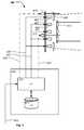
- Fig. 4illustrates a block diagram of an illumination device 401 according to present invention.
- the illumination device 401comprises a number of light sources arranged in first group of light sources 403 (white) and in a second group of light sources 405 (black) and first and second optical means.
- the first optical meanscomprises first light collectors 407 and first zoom optical means 409 and the second optical means comprises second light collectors 411 and second zoom optical means 413.
- the first groups of light sourcesare arranged as a ring around the second group of light sources.
- Each of the first and second groups of light sourcesare embodies as a multi-die LEDs comprising a number of dies emitting different color, e.g.
- the light collectorsare embodied as light mixers mixing the light from each multi-die LED into a homogeneous light beam.
- the light mixerscan for instance be embodied as any light mixer known in the art for instance polygonal or circular light rods, conical light mixers or as described in the Danish patent application DK PA 2010 70580 titled "OPTICAL LIGHT MIXER PROVIDING A HOMOGENIZED AND UNNIFORM LIGHT BEAM" filed the 23.
- the first zoom opticsis embodied as a transparent ring with a number of lenses and are connected to a first actuator 415.
- the second zoom opticsis embodied as a transparent disc with a number of lenses and is connected to a second actuator 417.
- the illumination devicecomprises further a control unit 419 comprising a processor 421 and a memory 423.
- the light collecting meansare positioned in the first position above the first group of light sources.
- the processoracts as controlling means and is adapted to control the first group of light sources 403 and the second group of light sources 405 respectively through communication means 425 (in solid lines) and 427 (in dotted lines).
- the processing meanscan thus control one of the groups of light sources without controlling the other group of light sources.
- the controlling meanscan for instance be adapted to control the color and/or intensity of the light sources and can be based on any type of communication signals known in the art of lightning e.g. PWM, AM, FM, binary signals etc.
- the first 403 and second 405 group of light sourcescan thus be controlled individually and independently and can thus be treated as two individually and independently groups of light sources. It is to be understood that the individually light sources of each groups can be controlled by the same control signal, supplied with individual control signals and/or grouped in sub-groups where each subgroup receive the same control signal.
- the communication means 425 and 427are illustrated as tree connections divided into the individual light source, however the skilled person will be able to construct many embodiments of the communication means, for instance the group of light sources may be coupled in series or in parallel. Alternatively both groups of light sources can be connected to the same data bus and controlled by the controller through a data bus using addressing.
- controlling meansis adapted to control the first 415 actuator and the second 417 actuator respectively through communication means 429 (in dashed-dotted line) and 431 (in dashed-dotted-dotted) by sending instructions to the first and second actuators. These instructions can instruct the first and/or second actuator to move the first and/or second zoom optics whereby the divergence of the first and second light beams can be changed.
- the illumination deviceis thus capable of creating many new and exciting mid-air effects and can also provide interesting light effects on a surface where on the light beam are projected.
- the controlling meanscan be adapted to control the first zoom optics based on a first zoom level parameter.
- the first zoom level parameteris indicative of the zoom level of the first light source beams and can for instance be stored in the memory or determined based other parameters.
- the first zoom level parametercan also be received through an input signal 433 as described below.
- Similar the controlling meanscan be adapted to control the second zoom optics based on a second zoom level parameter.
- the second zoom level parameteris indicative of the zoom level of the second light source beams and can for instance be stored in the memory or determined based other parameters.
- the second zoom level parametercan also be received through an input signal 433 as described below.
- controlling meansare adapted to activate the first and second actuators based on the first and second zoom parameters whereby the first zoom optics and second zoom optics ere moved in relation the first and second light collectors.
- controlling meanscan be adapted to control the second zoom optical means based on the first zoom level parameter of whereby the second light beams can be adapted to have substantially the same beam divergence and/or width as the first light beams in this way beam divergence and/or width of the first and second light beams will be regulated identically.
- controlling meanscan be adapted to control the first group of light sources based on a first color parameter and to control the second group of light sources based on a second color parameter.
- the first color parametercan for instance be indicative of the color that the first group light sources shall generate, for instance RGB values, color coordinates in color maps etc.
- Similar the second color parametercan be indicative of the color that the second group light sources shall generate, for instance RGB values, color coordinates in color maps etc.
- the controlling meanscan be adapted to control the second group of light sources based on the first color parameter of whereby the second group of light sources can be adapted generate substantial the same color as the color generated by the first group of light sources the light beams will in this way have the same color and appear as one common light beam and the illumination device can thus be used as a prior art illumination device.
- a color schemesuch that the color of the second array is adjusted such that the color of the second group of light sources is different but esthetic matches each other according to a predetermined color scheme. Similar the first group of light sources can be controlled based on the second color parameter.
- the controlling meansis adapted to control the first group of light sources, the second group of light sources, the first zoom optical means (through the first actuator) and second zoom optical means (through the second actuator) based on an input signal 433 indicative of a number of controlling parameters as known in the art of entertainment lighting.
- the input signal 433can be any signal capable of communication of parameters and can for instance be based on one of the following protocols USITT DMX 512, USITT DMX 512 1990, USITT DMX 512-A, DMX-512-A including RDM as covered by ANSI E1.11 and ANSI E1.20 standards or Wireless DMX.
- ACNdesignates Architecture for Control Networks; ANSI E1.17 - 2006).
- the input signalcan for instance be indicative of the first zoom level parameter; second zoom level parameter; the first color parameter and/or the second color parameter.
- a number of predefined effect functionscan also be stored in the memory and for instance comprise a number of instructions on how the zoom level of the first and second zoom optical means are regulated in relation to each other.
- These predefined effect functionscan for instance be executed and combined as described in the Danish patent applications DK PA 2011 00665 and DK PA 2011 00666 respectively titled “METHOD OF PRIORTIZING EFFECT FUNCTIONS IN AN ILLUMINATION DEVICE” and METHOD OF SYNCHRONIZING EFFECT FUNCTIONS IN AN ILLUMINATION DEVICE. Both applications filed by the applicant the 2nd of September 2011. Or alternatively as described in the PCT patent application PCT/DK2012/050326 titled “PRIORTIZING AND SYNCHRONIZING EFFECT FUNCTIONS” filed the 31 st of August 2012 by the applicant.
- the illumination devicecan also be integrated with an illumination device as described in the patent application, PCT/2011/ 050110 ( WO 2011/131197 ) titled “LED LIGHT FIXTURE WITH BACKGROUND LIGHTING” filed 5 th of April 5. 2011 by the applicant.
- an additional group of background light sourcescan be adapted to illuminate diffusing means in areas between the light beams.
- the background light sourcescan provide background light between the light beams through a number of light guides as described in the patent application PCT/2011/050112 ( WO 2011/131199 ) titled “LED LIGHT FIXTURE WITH BACKGROUND LIGHT EFFECTS” filed by the applicant the 5 th of April 5. 2011.
- the background light sourcescan constitute pixels in a background display as described in the patent application PCT/2011/050120 ( WO 2011/131200 ) titled "LED LIGHT FIXTURE WITH BACKGROUND DISPLAY EFFECTS" filed by the applicant the 12 th of April 5. 2011.
- the light sources of the first and secondcan be different and the optical properties of the first and second optic means also can be different and that the person skilled in the art of optics can is choosing and/or these components according to specified requirements.
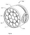
- Figures 5a and 5billustrate another embodiment of the illumination device 501 according to the present invention.
- Fig. 5aillustrates a perspective view
- fig. 5billustrates an exploded view.
- the illumination devicecomprises a light source module 535, a zoom module 537 and a cooling module 539.
- the three modulesare arranged in a housing comprising a first housing shell 541 a and a second housing shell 541 b, however the skilled person realize that the housing can be constructed in many different alternative ways can comprise any number of shells.
- the housingis formed as a head suitable to be rotatable connected to a yoke of a moving head light fixture as known in the art of moving head light fixtures and for instance as described in fig. 1a-b .
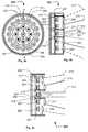
- the light source module 535is shown in fig. 6 and comprises a first group of light sources and second group of light sources mounted on a PCB 507.
- the two groups of light sourcescan be controlled individually and independently by a controller (not shown) as known in the art of lighting.
- the first group of light sourcescomprises 12 LEDs 503 arranged in a ring surrounding the second group of light sources, which comprises 7 LEDs 505.
- the LEDsare multi die LEDs each comprising a plurality of LED dies emitting different colors, whereby each LED can provide a large number of colors due to additive color mixing.
- First light collecting means 504are adapted to collect light from the first group of light sources 503 and to convert the collected light into the first light beams.
- second light collecting means 506are adapted to collect light from the second group of light sources 505 and to convert the collected light into the second light beams.
- center light collecting meanshave been exploded and illustrated that light collecting means is embodied as a light mixer which is supported by a light collecting means support 508.
- first and second groups of LEDsare embodied using same kind of multi die LEDs and the light collecting means are also of the same. However it is noticed that different kind of LED and light collector can be provided in other embodiments.
- the light collecting means and light collecting meansare adapted to extend through a light guide plate 510, which receives light from a number of background light sources embodied as a number of backgrounds LED 512 arrange at the peripheral surface of the PCT 507.
- the light guide plate 501is adapted to receive light from the background LEDs and guide the light from the background LEDs and to the areas between the light collecting means. Hereby the areas between the light collecting means are illuminated.
- the light guide plate 510functions thus as a background lighting as described in patent applications WO 2011/131197 and WO 2011/131199 .
- the zoom module 537comprises first zoom optics 509 and second zoom optics 511.
- the first zoom optics 509receive the first light beams from the first light collecting means 504 and can be moved by a first actuator 517 whereby the divergence of the first light beams can be changed.
- the second zoom optics 511receive the second light beams from the second light collecting means 506 and can be moved by a second actuator 519, whereby the divergence of the second light beams can be changed.
- the first and second zoom opticsare embodied as a number of optical lenses respectively supported by a first 543 and a second 545 lens holder, where the first lens holder 543 and second 545 lens holder respectively are connected to and movable by the first actuator 517 and the second actuator 519.
- the first and second zoom optical meanseach also can be embodied as a transparent bodies (for instance molded in polymer or glass) wherein the lens properties are formed.
- Fig. 7a -7dillustrate the illumination device of fig. 5a , 5b and 6 in four different settings, where outer perimeters of the first light beams are indicated by dashed lines 513 and the outer perimeters of the second light beams are indicated by solid lines 515.
- the first 509 and second 511 zoom opticsare arranged closest to and at the same distance from the light collecting means 504 and 506 s by the first 517 and second 519 actuators.
- the first and second light sourceswill have the same divergence and provide the widest light beam. If the first and second groups of light sources are instructed to provide light of different colors the common light beam will appear as a light beam having another color at its center part. However it is also possible to drive the first and second group of light sources at the same color whereby the light beam will appear as a one color light beam.
- the second zoom optics 511has been moved away from the light collectors by the second actuator and the second light beams are in the narrowest position.
- the center part of the common light beamis thus regulated independently of the peripheral part and the center part of the common light beam is thus dynamic changed in relation the peripheral part of the common light beam.
- the optical properties of the first and second zoom opticsare substantial identical, which makes it possible to control the first and second light beam approximately the same zoom range.
- the optical properties of the first and second zoom opticsmay be different in other embodiments.
Landscapes
- Engineering & Computer Science (AREA)
- General Engineering & Computer Science (AREA)
- Non-Portable Lighting Devices Or Systems Thereof (AREA)
- Circuit Arrangement For Electric Light Sources In General (AREA)
Description
- The present invention relates to an illumination device comprising a number of light sources and a number of optical means arranged in a housing. The number of optical means collect light from at least one of the light sources and convert the collected into a number of light beams and the light beams are emitted from said housing.
- In order to create various light effects and mood lighting in connection with concerts, live shows, TV shows, sport events or as a part on architectural installation, light fixtures creating various effects are getting more and more used in the entertainment industry. Typically entertainment light fixtures create a light beam having a beam width and a divergence and can for instance be wash/flood fixtures creating a relatively wide light beam with a uniform light distribution or it can be profile fixtures adapted to project image onto a target surface.
- Light emitting diodes (LED) are, due to their relatively low energy consumption or high efficiency, long lifetime, and capability of electronic dimming, becoming more and more used in connection with lighting applications. LEDs are used in lighting applications for general illumination such as wash/flood lights illuminating a wide area or for generating wide light beams e.g. for the entertainment industry and/or architectural installations. For instance like in products like MAC101™, MAC301™, MAC40™, MAC Aura™, Stagebar2™, Easypix™, Extube™, Tripix™, Exterior 400™ series provided by the applicant, Martin Professional A/S. Further LEDs are also being integrated into projecting systems where an image is created and projected towards a target surface, for instance like in the products MAC 350 Entour™ or Exterior 400 Image Projector™ also provided by the applicant, Martin Professional A/S.
WO 2006/113745 discloses a lighting apparatus comprises a light panel having a panel frame, and a plurality of LEDs or other light elements secured to the panel frame. Lenses and/or filters are adjusted in distance from the light elements, by for example moving the lenses/filters into different slot positions of the frame, to alter characteristics of the emitted light. Focal lenses, diffusion lenses, and color filters may be used individually or in combination. A compound lens includes lens elements having different focusing characteristics arranged in a pattern can be arranged in front of the LEDs and movement of the compound lens results in synchronously movement of the different lens elements in respect to the LED. AS a consequence the focal or spread of the light changed by the different lens elements will change simultaneously. Through groupwise control of the intensity of the light elements, the different characteristics are emphasized or de-emphasized.WO 2007/049176 discloses a plurality of light emitting diode dies (LED) with associated secondary optics, which produce different light distribution patterns, are combined to produce an efficient light source having a desired illumination pattern. By way of example, a first LED may include a lens that produces a light distribution pattern with a maximum intensity at the center while a second LED may use a lens that produces a light distribution pattern with a maximum intensity that surrounds the maximum intensity of the pattern produced by the first LED. The light from the LEDs can then be combined to produce a desired illumination pattern. Additional LEDs and lenses, e.g., having different light distribution patterns may be used if desired. Moreover, a variable current driver may be used to vary the amount of current to the different LEDs, such that the combined illumination pattern may be varied as desired.WO 2010/084187 discloses a spotlight comprising light emitting diode modules wherein each LED module comprises at least two light emitting diodes with different light emission spectra and a light mixer, wherein each light mixer is arranged at one side of the light mixer in cooperation with an assigned LED module and each light mixer is configured to mix the different light emission spectra of the at least two LEDs of the assigned LED module to form a light beam, and wherein exit surfaces at the other side of the light mixers are arranged next to each other in a matrix with its light beams of the light mixers form a common light beam and a focusing optics for focusing the common light beam.- It is common to incorporate midair light effects into light shows. Midair effects are created by creating a well-defined light beam which is partially scattered by haze or smoke particle in the air whereby the audience can see the light beam in the air. The midair light beams are often created in the head of a moving head light fixture where the head is rotatable connected to a yoke which is rotatable connected to a base and the light beam can as a consequence be moved around in the air. Typically midair light effects are created by profile moving heads comprising projecting systems as these created a bright well defined light beam or by a hybrid of a projecting and a wash system often called beam systems. Typically beam systems has focusing properties like a projecting system, however the focusing in beam systems is not as sharp as dedicated projecting systems and the beams systems creates a more narrow light beam compared to wash lights. There is today a number of different products (e.g. The MAC 250 Beam™ or the MAC 2000 Beam™ provided by Martin Professional A/S) which is cable of providing such light beams and many of these can create light beams with variable beam diverges and/or collimated light beams having variable beam diameter's. In beam systems, the light beam can be split into multiple numbers of light beams by incorporating prisms having a number of facets into the optical system or by incorporating gobos having a number of smaller apertures. As a consequence the multiple light beams are substantially identical. Further Beam systems are based on traditional light sources as discharge lamps as midair effect requires very bright light beams having relatively narrow beam properties and LEDs have not previously by used when creating beam systems. Yet another fact is that light designers and producers continuously try to create and use new and interesting light effects in the light shows.
US 2011/235326 A1 discloses an illumination device according to the preamble ofclaim 1.- The object of the present invention is to solve the above described limitations related to prior art and provide a beam system which can create new and interesting midair effects which are independent of a viewer's position. This is achieved by an illumination device and method as described in the independent claims. The dependent claims describe possible embodiments of the present invention. The advantages and benefits of the present invention are described in the detailed description of the invention.
Fig. 1 a and 1 b illustrate an example of a moving head lighting fixture according to prior art;fig. 2a- 2d illustrate an embodiment of an illumination device according to the present invention;fig. 3a - 3d illustrate another embodiment of an illumination device according to the present invention;fig. 4 illustrates a block diagram of a illumination device according to the present invention;fig. 5a and5b illustrate another embodiment of an illumination device according to the present invention;fig. 6 illustrates an embodiment of the LED and light collecting means of the illumination device infig. 5a and5b ;fig. 7a-7d illustrate different settings of the illumination device offig. 5a and5b .- The present invention is described in view of a moving head lighting fixture including a number of LEDs that generate a light beam, however the person skilled in the art realizes that the present invention relates to illumination devices using any kind of light source such as discharge lamps, OLEDs, plasma sources, halogen sources, fluorescent light sources, etc. and/or combinations thereof. It is to be understood that the illustrated embodiments are simplified and illustrate the principles of the present invention rather than showing an exact embodiment. The skilled person will thus understand that the present invention can be embodied in many different ways and also comprise further components in addition to the shown components.
Figure 1 a-1 b illustrate an illumination device according to prior art, wherefig. 1 a is a perspective view andfig 1 b is an exploded view. The illumination device is a movinghead lighting fixture 101 comprising abase 103, ayoke 105 rotatable connected to the base and a head rotatable connected 107 to the yoke.- In the illustrated embodiment, the head comprises a number of light sources and a number of light collecting means 109 arranged in the
head housing 111. The light collecting means collect light from at the light sources and convert the collected light into a number of source light beams 113 (only one illustrated), and which are emitted from the housing. - In the illustrated embodiment the
head housing 107 is a "bucket" shapedhead housing 111 wherein a display 115 (visible from the rear side of the head), main PCB 117 (Printed Circuit Board), afan 119, aheat sink 121, aLED PCB 123, and a lens assembly are stacked. TheLED PCB 123 comprises anumber LEDs 124 and the lens assembly comprises alens holder 125 and a lens array where the lenses constitute the light collecting means 109. Each light collecting means is adapted to collect light form each LED and convert the collected light into alight source beam 113. The head is rotatable connected to the yoke by twotilt bearings 127, which are supported by theyoke 105. Atilt motor 129 is adapted to rotate the head through atilt belt 131 connected to one of thetilt bearings 127. The yoke comprises two interlockedyoke shell parts 132 which are mounted to ayoke frame 134 whereon the tilt bearings, tilt motor, pan motor and pan bearing are arranged. TheLED PCB 123 comprises a number of LEDs emitting light and which in cooperation with the light collecting means 109 in the lens array generate a number of light source beams. The main PCB comprises controlling circuits and driving circuits (not shown) for controlling the LEDs as known in the art of illumination devices. The main PCB comprises further a number of switches (not shown) which extend through a number of holes in thehead housing 111. The switches and display act as a user interface allowing a user to communicate with the moving head lighting fixture. - The yoke are connected to a pan bearing 133 rotatable connected to the
base 103. Apan motor 135 is adapted to rotate the yoke through apan belt 137 connected to thepan bearing 133. The base comprises 5-Pin XLR male 139 and female 141 connectors for DMX signals as known in the art of entertainment lighting;input 143 andoutput power 145 connectors, power supply PCB's (not shown) and fan (not shown). The fan forces air into the base through vent holes 147. - This prior art illumination device uses multiple LEDs to replace a single light source as known prior the introduction of the LED component as a widely used light source. However such illumination device changes its visible appearance as the multiple light sources are now exposed to the viewer and the light emits from a larger area. If the light luminaries are a color mixing version with single color LEDs, then all LED colors used are visible. However some customers dislike the look of multiple light dots. Instead a more uniform, even light exit is requested, to avoid the cheap looking "funfair" look with an extreme amount of light sources. The light beams merges into one common light beam a distance from the light collecting means. When it comes to midair effects such illumination device can only well-defined light beams having the same color. It is noted the some prior art illumination systems like the one in
fig. 1 a and 1 b can comprise a zooming system enabling the user to adjust the divergence of the light beam. However LED based illumination devices are designed to have a large divergence and are thus primarily used for illuminating larger areas of e.g. a stage. The illuminating device illustrated infig. 1 a and 1 b is just one example of a prior art illumination derive and the skilled person realize that a large number of different embodiments provided by a large number of manufactures exits. Figures 2a-d illustrate a simplified embodiment of theillumination device 201 according to the present invention.Fig. 2a illustrate a top view andfig. 2b ,2c, 2d illustrate a cross sectional view along line A-A in respectively a first setting, second setting and third setting.- The
illumination device 201 comprises a number of light sources arranged in a first group of light sources 203 (illustrated as white quadrangles) and in a second group of light sources 205 (illustrated as black quadrangles). In this embodiment the light sources are LEDs mounted on a PCB 207 (printed circuit board) and the two groups of light sources can be controlled individually and independently of by a controller (not shown) as known in the art of lighting. The skilled person realizes that the illumination device also can be adapted to divide each group of light sources into a number of sub-groups which also can be controlled individually and that it is also possible to control each single light source individually. First and secondoptical means
The firstoptical means 209 is adapted to collect light from the first group of light sources and convert the collected light into a number of first light beams where the outer perimeter of the first light beams are indicated by dashedlines 213. The second optical means 211 is adapted to collect light from the second group of light sources and convert the collected light into a number of second light beams where the outer perimeter of the second light beams are indicated bysolid lines 215. The mentioned components are arranged in ahousing 210 and the first and second light beams are emitted from the housing. The first and second optical means can be embodied as any optical component capable of collecting light from the light sources and convert the light into light beams and can for instance be optical lenses, light mixers, TIR lenses etc. - Further the first optical means comprises
first zoom optics 209 capable of changing the divergence and/or beam width of the first light beams 213 and the second optical means comprisessecond zoom optics 211 capable of changing the divergence and/or the beam width of the second light beams 215. The controlling means is adapted to control the first zoom optics and the second zoom optics independently. In the illustrated embodiment the first and second zoom optics are embodied as a number a plano-convex lenses embodied in two transparent plates. The first and second zoom optics are respectively connected to a first 217 and second 219 actuator, where the first actuator is adapted to move the first zoom optics in relation to thefirst group 203 of light sources and where the second actuator is adapted to move the second zoom optics in relation thesecond group 205 of light sources. The controlling means can control the actuators as known in the art of entertainment lightning. This setup makes it possible to control the zoom level of the first and second light beams independently of and at the same time control the light created by the first and second groups of light sources. The consequence is that a new and interesting midair light effect can be created as a multiple color light beam is provided where the divergence and/or beam width of the different colored light beam parts can be varied dynamically and in relation to each other. This is achieved as the intensity and/or color of thefirst light beam 213 can be controlled by the controlling means and the divergence and/or beam width of the first light beams can be controlled by the controller by moving the first zoom optics. At the same time the intensity and/or color of the secondlight beams 215 can be controlled by the controlling means and the divergence and/or second light beams width can be controlled by the second zoom optics. - The skilled person realizes that many mid-air effect can be created by such illumination device and realizes also the interesting color patterns can be created on a surfaces when the light beams are projected onto such surface. The first and second light beams will hit different areas on the surface and their mutual relationship can be changed by controlling the first and second zoom optics. The skilled person realize also that the first and second light beams may overlap in some zones and that an observer will observe these zones as a combination of the color of the first light beam and the color of the second light beam as known in the art of color mixing. For instance in the case that the first light beam is green and that the second light beam is red and they are run at approximately the same intensity (as observed by a human) then a human observer would see the overlapping zones as yellow. This can be used to divide the common light beam into further zones having a mixed color. If desired, it is also possible to minimize the appearance of mixed areas/sections by driving one of the light beams at a higher intensity than the other as the most intense light beam now will be the dominating and the less intense light beam will only be observed in nonoverlapping zones. The person skilled in optics will also be able to define the optics such that the amount of overlapping zoned are minimized for instance by designing the first and second optical means such that the first and second light are substantially aligned adjacent to each other in the entire zooming range.
- The top view in
fig. 2a illustrates that at least one of the light sources of the second group is arrange between at least two of the light sources of the first group. This makes it possible to provide the central part the light beam with a different color than the surrounding part and where the divergence and/or beam width of the central part can be varied in relation to the surrounding part of the light beam. In fact the light sources of the first group of light sources are arranged in a ring surrounding the second group of light sources. This provides a substantially symmetric multicolored light beam where the divergence and/or beam width of the central and the peripheral part can be changed independently of each other. The light beam will have the same looked from all sides which is useful when the illumination device is embodied in a head of a moving head light fixture like the one described infig. 1 a and 1 b, as the moving head can make the multiple colored light beam movie in many directions in the air. - For instance
fig. 2b, fig. 2c and fig. 2d illustrate three different settings of the illumination device creating different multiple colored light beams. Infig. 2b the first and second groups of light sources are instructed to provide light of different colors and the intensity of the light provided by the second light sources are higher than the intensity of the light provide by the first group of light sources. Further the first 209 and second 211 zoom optics are arranged at the same distance from the light sources by the first and second actuators. In this setting the first and second light sources will have the same divergence and the common light beam will appear as a light beam having another color at its center part. Infig. 2c thesecond zoom optics 211 has been moved by the second actuator and the secondlight beams 215 are substantial parallel. The center part of the common light beam is thus regulated independently of the peripheral part and the center part of the common light beam is thus dynamic changed in relation the peripheral part of the common light beam. Infig. 2d the first zoom optics has been moved to the same zoom level as the second zoom optics and the consequence is that a substantial parallel light beam with a parallel center of different color is created. It is noted that the settings illustrated infig. 2b-2d only illustrates three settings and that there are many settings and that the settings can be change dynamical whereby an unlimited number of new and interesting midair effects can be created. Figures 3a-c illustrate a simplified embodiment of another embodiment of anillumination device 301 according to the present invention.Fig. 3a illustrate a top view andfig. 3b and fig. 3c illustrate a cross sectional view along line B-B in respectively a first setting and second setting. Only the differences between theillumination device 301 and theillumination device 201 infig. 2a-d have been described and substantially identical components have been labeled with identical reference numbers as used infig. 2a-d and will not be described in this part.- In this embodiment the first optical means comprises first light collecting means 303 adapted to collect light from the first group of
light sources 203 and to convert the collected light into the first light beams and where thefirst zoom optics 209 receives the first light beams from the first light collecting means 303. Similarly the second optical means comprises second light collecting means 305 adapted to collect light from the second group oflight sources 205 and to convert the collected light into the second light beams and where thesecond zoom optics 211 receives the first light beams from the second light collecting means 305. The first 303 and second 305 light collecting means can be embodied as any optical component capable of collecting light from the light sources and convert the light into light beams and can for instance be optical lenses, light mixers, TIR lenses etc. The first 303 and second 305 light collecting means can collect much of the light for the light sources and form a number of light beams which can be adjusted by the first and second zoom optics. In the case that the light sources are multiple die LEDs having dies emitting different colors, the light collecting means can be embodied as light mixers capable of mixing the light form the different dies into a homogenized light beam. The first actuators is capable of moving the first zoom optics in relation to the first light collecting 303 means and the second actuators is capable of moving the second zoom optics in relation to the second light collecting means 305. - Further in this embodiment the center light sources constitute a
third group 307 of light sources, which by the controlling means can be controlled independently of the other groups of light sources. Third light collecting means 309 andthird zoom optics 311 are capable creating a third light beam illustrated bydotted lines 313. Athird actuator 315 can move the third zoom optics whereby the divergence of the thirdlight beam 313 can be changed.
As shown infig. 3b and 3c the common light beam created by the illumination device can have three colors which can be adjusted in many ways as described above. It is to be understood that the light sources can be arranged in any number of groups and the corresponding zoom optics can be individual controlled by the controller. The skilled person will thus be able to construct a large number of illumination devices falling within the scope of the claims. Fig. 4 illustrates a block diagram of anillumination device 401 according to present invention. As described above theillumination device 401 comprises a number of light sources arranged in first group of light sources 403 (white) and in a second group of light sources 405 (black) and first and second optical means. The first optical means comprisesfirst light collectors 407 and first zoom optical means 409 and the second optical means comprises secondlight collectors 411 and second zoom optical means 413. Like the illumination devices illustrated infig. 2a-d and fig 3a-c the first groups of light sources are arranged as a ring around the second group of light sources. Each of the first and second groups of light sources are embodies as a multi-die LEDs comprising a number of dies emitting different color, e.g. a red die emitting red light, a blue light emitting blue light, a green die emitting green light and a white die emitting white light, however the skilled person realize that many combinations of such multi-die LED can be used. The light collectors are embodied as light mixers mixing the light from each multi-die LED into a homogeneous light beam. The light mixers can for instance be embodied as any light mixer known in the art for instance polygonal or circular light rods, conical light mixers or as described in the Danish patent application DK PA2010 70580 PCT/DK2011/050450 WO 2012/083957 . Both applications have been filed by the applicant. The first zoom optics is embodied as a transparent ring with a number of lenses and are connected to afirst actuator 415. The second zoom optics is embodied as a transparent disc with a number of lenses and is connected to asecond actuator 417.- The illumination device comprises further a
control unit 419 comprising aprocessor 421 and amemory 423. In the block diagram the light collecting means are positioned in the first position above the first group of light sources. The processor acts as controlling means and is adapted to control the first group oflight sources 403 and the second group oflight sources 405 respectively through communication means 425 (in solid lines) and 427 (in dotted lines). The processing means can thus control one of the groups of light sources without controlling the other group of light sources. The controlling means can for instance be adapted to control the color and/or intensity of the light sources and can be based on any type of communication signals known in the art of lightning e.g. PWM, AM, FM, binary signals etc. The first 403 and second 405 group of light sources can thus be controlled individually and independently and can thus be treated as two individually and independently groups of light sources. It is to be understood that the individually light sources of each groups can be controlled by the same control signal, supplied with individual control signals and/or grouped in sub-groups where each subgroup receive the same control signal. The communication means 425 and 427 are illustrated as tree connections divided into the individual light source, however the skilled person will be able to construct many embodiments of the communication means, for instance the group of light sources may be coupled in series or in parallel. Alternatively both groups of light sources can be connected to the same data bus and controlled by the controller through a data bus using addressing. Further the controlling means is adapted to control the first 415 actuator and the second 417 actuator respectively through communication means 429 (in dashed-dotted line) and 431 (in dashed-dotted-dotted) by sending instructions to the first and second actuators. These instructions can instruct the first and/or second actuator to move the first and/or second zoom optics whereby the divergence of the first and second light beams can be changed. As described above the illumination device is thus capable of creating many new and exciting mid-air effects and can also provide interesting light effects on a surface where on the light beam are projected. - The controlling means can be adapted to control the first zoom optics based on a first zoom level parameter. The first zoom level parameter is indicative of the zoom level of the first light source beams and can for instance be stored in the memory or determined based other parameters. The first zoom level parameter can also be received through an
input signal 433 as described below. Similar the controlling means can be adapted to control the second zoom optics based on a second zoom level parameter. The second zoom level parameter is indicative of the zoom level of the second light source beams and can for instance be stored in the memory or determined based other parameters. The second zoom level parameter can also be received through aninput signal 433 as described below. In the illustrated embodiment the controlling means are adapted to activate the first and second actuators based on the first and second zoom parameters whereby the first zoom optics and second zoom optics ere moved in relation the first and second light collectors. Alternatively the controlling means can be adapted to control the second zoom optical means based on the first zoom level parameter of whereby the second light beams can be adapted to have substantially the same beam divergence and/or width as the first light beams in this way beam divergence and/or width of the first and second light beams will be regulated identically. However it is also possible to integrate a zoom scheme such that the zoom level of the second light beams is adjusted according the zoom level of the first light beams, but such that the zoom level of the second light beams is offset of the zoom level of the first light beams . Similar the first zoom optics can be controlled based on the second zoom parameter. - Further the controlling means can be adapted to control the first group of light sources based on a first color parameter and to control the second group of light sources based on a second color parameter. The first color parameter can for instance be indicative of the color that the first group light sources shall generate, for instance RGB values, color coordinates in color maps etc. Similar the second color parameter can be indicative of the color that the second group light sources shall generate, for instance RGB values, color coordinates in color maps etc. Alternatively the controlling means can be adapted to control the second group of light sources based on the first color parameter of whereby the second group of light sources can be adapted generate substantial the same color as the color generated by the first group of light sources the light beams will in this way have the same color and appear as one common light beam and the illumination device can thus be used as a prior art illumination device. However it is also possible to integrate a color scheme such that the color of the second array is adjusted such that the color of the second group of light sources is different but esthetic matches each other according to a predetermined color scheme. Similar the first group of light sources can be controlled based on the second color parameter.
- In one embodiment the controlling means is adapted to control the first group of light sources, the second group of light sources, the first zoom optical means (through the first actuator) and second zoom optical means (through the second actuator) based on an
input signal 433 indicative of a number of controlling parameters as known in the art of entertainment lighting. Theinput signal 433 can be any signal capable of communication of parameters and can for instance be based on one of the followingprotocols USITT DMX 512,USITT DMX 512 1990, USITT DMX 512-A, DMX-512-A including RDM as covered by ANSI E1.11 and ANSI E1.20 standards or Wireless DMX. ACN designates Architecture for Control Networks; ANSI E1.17 - 2006). The input signal can for instance be indicative of the first zoom level parameter; second zoom level parameter; the first color parameter and/or the second color parameter. - A number of predefined effect functions can also be stored in the memory and for instance comprise a number of instructions on how the zoom level of the first and second zoom optical means are regulated in relation to each other. These predefined effect functions can for instance be executed and combined as described in the Danish patent applications DK PA
2011 00665 2011 00666 PCT/DK2012/050326 - The illumination device according to the present invention can also be integrated with an illumination device as described in the patent application,
PCT/2011/ 050110 (WO 2011/131197 ) titled "LED LIGHT FIXTURE WITH BACKGROUND LIGHTING" filed 5th of April 5. 2011 by the applicant. In such embodiment an additional group of background light sources can be adapted to illuminate diffusing means in areas between the light beams. The background light sources can provide background light between the light beams through a number of light guides as described in the patent applicationPCT/2011/050112 (WO 2011/131199 ) titled "LED LIGHT FIXTURE WITH BACKGROUND LIGHT EFFECTS" filed by the applicant the 5th of April 5. 2011. Alternatively the background light sources can constitute pixels in a background display as described in the patent applicationPCT/2011/050120 (WO 2011/131200 ) titled "LED LIGHT FIXTURE WITH BACKGROUND DISPLAY EFFECTS" filed by the applicant the 12th of April 5. 2011. - It is noted that the light sources of the first and second can be different and the optical properties of the first and second optic means also can be different and that the person skilled in the art of optics can is choosing and/or these components according to specified requirements.
Figures 5a and5b illustrate another embodiment of theillumination device 501 according to the present invention.Fig. 5a illustrates a perspective view andfig. 5b illustrates an exploded view.- In this embodiment the illumination device comprises a
light source module 535, azoom module 537 and acooling module 539. The three modules are arranged in a housing comprising afirst housing shell 541 a and asecond housing shell 541 b, however the skilled person realize that the housing can be constructed in many different alternative ways can comprise any number of shells. In the illustrated embodiment the housing is formed as a head suitable to be rotatable connected to a yoke of a moving head light fixture as known in the art of moving head light fixtures and for instance as described infig. 1a-b . - The
light source module 535 is shown infig. 6 and comprises a first group of light sources and second group of light sources mounted on aPCB 507. The two groups of light sources can be controlled individually and independently by a controller (not shown) as known in the art of lighting. In this embodiment the first group of light sources comprises 12LEDs 503 arranged in a ring surrounding the second group of light sources, which comprises 7LEDs 505. However it is noted that any number of light sources can be provided. The LEDs are multi die LEDs each comprising a plurality of LED dies emitting different colors, whereby each LED can provide a large number of colors due to additive color mixing. - First light collecting means 504 are adapted to collect light from the first group of
light sources 503 and to convert the collected light into the first light beams. Similarly second light collecting means 506 are adapted to collect light from the second group oflight sources 505 and to convert the collected light into the second light beams. For instance for illustrative purpose the center light collecting means have been exploded and illustrated that light collecting means is embodied as a light mixer which is supported by a light collecting meanssupport 508. In the illustrated embodiment the first and second groups of LEDs are embodied using same kind of multi die LEDs and the light collecting means are also of the same. However it is noticed that different kind of LED and light collector can be provided in other embodiments. - The light collecting means and light collecting means are adapted to extend through a
light guide plate 510, which receives light from a number of background light sources embodied as a number of backgrounds LED 512 arrange at the peripheral surface of thePCT 507. Thelight guide plate 501 is adapted to receive light from the background LEDs and guide the light from the background LEDs and to the areas between the light collecting means. Hereby the areas between the light collecting means are illuminated. Thelight guide plate 510 functions thus as a background lighting as described in patent applicationsWO 2011/131197 andWO 2011/131199 . - Returning to
fig. 5a and5b thezoom module 537 comprisesfirst zoom optics 509 andsecond zoom optics 511. Thefirst zoom optics 509 receive the first light beams from the first light collecting means 504 and can be moved by afirst actuator 517 whereby the divergence of the first light beams can be changed. Similar, thesecond zoom optics 511 receive the second light beams from the second light collecting means 506 and can be moved by asecond actuator 519, whereby the divergence of the second light beams can be changed. - In the illustrated embodiment the first and second zoom optics are embodied as a number of optical lenses respectively supported by a first 543 and a second 545 lens holder, where the
first lens holder 543 and second 545 lens holder respectively are connected to and movable by thefirst actuator 517 and thesecond actuator 519. It is noticed the first and second zoom optical means each also can be embodied as a transparent bodies (for instance molded in polymer or glass) wherein the lens properties are formed. Fig. 7a -7d illustrate the illumination device offig. 5a ,5b and6 in four different settings, where outer perimeters of the first light beams are indicated by dashedlines 513 and the outer perimeters of the second light beams are indicated bysolid lines 515.- In
fig. 7a the first 509 and second 511 zoom optics are arranged closest to and at the same distance from the light collecting means 504 and 506 s by the first 517 and second 519 actuators. In this setting the first and second light sources will have the same divergence and provide the widest light beam. If the first and second groups of light sources are instructed to provide light of different colors the common light beam will appear as a light beam having another color at its center part. However it is also possible to drive the first and second group of light sources at the same color whereby the light beam will appear as a one color light beam. - In
fig. 7b thesecond zoom optics 511 has been moved away from the light collectors by the second actuator and the second light beams are in the narrowest position. The center part of the common light beam is thus regulated independently of the peripheral part and the center part of the common light beam is thus dynamic changed in relation the peripheral part of the common light beam. - In
fig. 7c the first zoom optics has been moved to the same zoom level as the second zoom optics and the consequence is that the common light beam is in it's narrowest position. - In
fig. 7d thesecond zoom optics 511 has been moved back towards the light collectors by the second actuator and the second light beams are in the widest position, whereas the peripheral part of the light beam are in the narrowest positions. This provides the effect that the center part eventually due to the fact that it has a larger divergence would extend the peripheral part a distance away from the illumination device. - It is noted that the settings illustrated in
fig. 7a-7d only illustrates four outer settings and that there are many intermediate settings and that the settings can be change dynamical whereby an unlimited number of new and interesting midair effects can be created. - In the embodiment illustrated in
fig. 5-7 the optical properties of the first and second zoom optics are substantial identical, which makes it possible to control the first and second light beam approximately the same zoom range. However it is understood that the optical properties of the first and second zoom optics may be different in other embodiments.
Claims (15)
- An illumination device (201, 301, 401, 501) comprising:• a number of light sources arranged in at least a first group of light sources (203, 403, 503) and in a second group of light sources (205, 405, 505);• first optical means adapted to convert light from said first group of light sources into a number of first light beams (213), said first optical means comprises first zoom optics (209, 409, 509) capable of changing the divergence and/or beam width of said first light beams;• second optical means adapted to convert light from said second group of light sources into a number of second light beams (215), said second optical means comprises second zoom optics (211, 413, 511) capable of changing the divergence and/or the beam width of said second light beams;• controlling (419) means adapted to control said first zoom optics and said second zoom optics independently;characterized in that said controlling means (419) is adapted to control said first group of light sources and said second group of light sources independently of each other and at least one of said light sources of said second group is arranged between at least two of said light sources of said first group and where said light sources of said first group of light sources and said first zoom optics are arranged in a ring surrounding said second group of light sources and said second zoom optics.
- An illumination device according to claim 1characterized in that said first zoom optics is movable in relation to said first group of light sources andin that said second zoom optics is movable in relation to said second group of light sources, andin that said first zoom optics and said second zoom optics can be moved independently.
- An illumination device according to claims 1-2characterized in that a first actuator (217, 415, 517) is adapted to move said first zoom optics in relation to said first group of light sources and where a second actuator (209, 417, 519) is adapted to move said second zoom optics in relation the second group of light sources.
- An illumination device according to claims 1-3characterized in that at least one of:• said first optical means comprises first light collecting means (303, 403, 504) adapted to collect light from said first group of light sources and convert said collected light into said number of first light beams and where said first zoom optics receives said first light beams from said first light collecting means;
or• said second optical means comprises second light collecting means (305, 405, 506) adapted to collect light from said second group of light sources and convert said collected light into said number of second light beams and where said second zoom optics receives said second light beams from said second light collecting means. - An illumination device according to claim 4characterized in that said first zoom optics is movable in relation to said first light collecting means and said second zoom optics is movable in relation to said second light collecting means, andin that said first zoom optics and said second zoom optics can be moved independently.
- An illumination device according to claims 1-5characterized in that said controlling means is adapted to control at least one of:• said first zoom optics based on a first zoom level parameter• said second zoom optics based on a second zoom level parameter.• said first group of light sources based on a first color parameter;• said second group of light sources based on a second color parameter.
- An illumination device according to claims 1-6characterized in that said controlling means is adapted to control said first zoom optics and said second zoom optics based on a zoom level parameter and such that the zoom level of the second light beams is offset of the zoom level of the first light beams.
- An illumination device according to claims 1-7characterized in that at least one of said first zoom optics or said second zoom optics is embodied as a transparent body wherein the lens properties of said zoom optics are formed.
- An illumination device according to claims 1-8characterized in that said first zoom optics is embodied a transparent ring with a number of lenses andin that said second zoom optics is embodied a transparent disc with a number of lenses.
- An illumination device according to claims 1-7characterized in that said first zoom optics comprises a number of optical lenses (509) supported by a first lens holder (543) and said second zoom optics comprises number of optical lenses (511) supported by a second lens holder (545), where said first lens holder is connected to a first actuator (517) and said second lens holder is connected to a second actuator (519), where said first actuator is adapted to move said first zoom optics in relation to said first group of light sources and where said second actuator is adapted to move said second zoom optics in relation the second group of light sources.
- An illumination device according to claims 1-10characterized in that the optical properties of said first zoom optics and said second zoom optics are different.
- A method of controlling an illumination device, said illumination device comprises:• a number of light sources arranged in at least a first group of light sources and in a second group of light sources;• first optical means adapted to convert light from said first group of light sources into a number of first light beams;• second optical means adapted to convert light from said second group of light sources into a number of second light beams;said method comprises the steps of:• controlling the beam divergence and/or width of said first light beams using first zoom optics;• controlling the beam divergence and/or width of said second light beams using second zoom optics;• controlling said first zoom optics and said second zoom optics independently of each other;characterized in that said method comprises the step of:• controlling said first group of light sources and said second group of light sources independently;• arranging at least one of the light source of said second group between at least two of said light sources of said first group and arranging said light sources of said first group and said first zoom optics in a ring surrounding said light sources of said second group and said second zoom optics.
- A method according to claim 12characterized in that at least one of:• said step of controlling the beam divergence and/or width of said first light beams comprises the step of moving said first zoom optics in relation to said first light sources;
or• said step of controlling the beam divergence and/or width of said second light beams comprises the step of moving said second zoom optics in relation to said first light sources;wherein said step of moving said first zoom optics in relation to said first light sources and said step of moving said second zoom optics in relation to said second light sources can be performed independently. - A method according to claims 12-13characterized in that at least one of:• said step of controlling the beam divergence and/or width of said first light beams is based on a first zoom level parameter; or• said step of controlling the beam divergence and/or width of said second light beams is based on a second zoom level parameter.
- A method according to claims 12-14characterized in comprising at least one of the steps of:• controlling said first group of light sources based on a first color parameter;
or• controlling said second group of light sources based on a second color parameter.
Applications Claiming Priority (2)
| Application Number | Priority Date | Filing Date | Title |
|---|---|---|---|
| DKPA201170579 | 2011-10-23 | ||
| PCT/DK2012/050388WO2013060329A1 (en) | 2011-10-23 | 2012-10-19 | Illumination device with multi-colored light beam |
Publications (3)
| Publication Number | Publication Date |
|---|---|
| EP2769143A1 EP2769143A1 (en) | 2014-08-27 |
| EP2769143A4 EP2769143A4 (en) | 2015-05-06 |
| EP2769143B1true EP2769143B1 (en) | 2016-09-21 |
Family
ID=48167139
Family Applications (1)
| Application Number | Title | Priority Date | Filing Date |
|---|---|---|---|
| EP12844393.4AActiveEP2769143B1 (en) | 2011-10-23 | 2012-10-19 | Illumination device with multi-colored light beam |
Country Status (6)
| Country | Link |
|---|---|
| US (1) | US9562672B2 (en) |
| EP (1) | EP2769143B1 (en) |
| CN (2) | CN110345414A (en) |
| DE (1) | DE202012013045U1 (en) |
| DK (2) | DK177878B1 (en) |
| WO (1) | WO2013060329A1 (en) |
Families Citing this family (78)
| Publication number | Priority date | Publication date | Assignee | Title |
|---|---|---|---|---|
| US10210793B2 (en) | 2008-03-11 | 2019-02-19 | Robe Lighting S.R.O. | Array of LED array luminaires |
| EP2718619B8 (en)* | 2011-06-10 | 2017-06-28 | Martin Professional ApS | Mechanichal color mixing device |
| US9500340B2 (en)* | 2011-10-25 | 2016-11-22 | A-Dec, Inc. | Dental light using LEDs |
| DK2920511T3 (en)* | 2012-11-14 | 2020-07-27 | Coelux Srl | ARTIFICIAL LIGHTING DEVICE FOR GENERATING NATURAL LIGHT |
| TW201504565A (en)* | 2013-04-26 | 2015-02-01 | 萬恒國際有限公司 | Long distance high intensity led light with adjustable focus |
| US9303846B2 (en) | 2013-05-31 | 2016-04-05 | GE Lighting Solutions, LLC | Directional lamp with adjustable beam spread |
| ITMI20131386A1 (en)* | 2013-08-12 | 2015-02-13 | Clay Paky Spa | STAGE PROJECTOR |
| ITMI20131385A1 (en)* | 2013-08-12 | 2015-02-13 | Clay Paky Spa | SPOTLIGHT HEADLAMP, IN PARTICULAR SPOTLIGHT WITH MULTISORGENT STAGE |
| US9374854B2 (en)* | 2013-09-20 | 2016-06-21 | Osram Sylvania Inc. | Lighting techniques utilizing solid-state lamps with electronically adjustable light beam distribution |
| US10015868B2 (en)* | 2014-11-03 | 2018-07-03 | Osram Sylvania Inc. | Solid-state lamps with electronically adjustable light beam distribution |
| WO2015049704A1 (en)* | 2013-10-02 | 2015-04-09 | D.T.S. Illuminazione S.R.L. | Floodlight |
| CN105637289B (en)* | 2013-10-05 | 2019-11-26 | 哈曼专业丹麦公司 | Lighting device with rotation zoom lens |
| US9752748B2 (en) | 2013-12-05 | 2017-09-05 | Martin Professional Aps | Projecting light fixture with a plurality of lenslets packed in an optimized dense circular pattern |
| DK2881650T3 (en) | 2013-12-05 | 2017-06-06 | Martin Professional Aps | Light collector with a plurality of bundled micro lenses with different optical power |
| EP2881653B1 (en)* | 2013-12-05 | 2017-11-01 | Martin Professional ApS | Illumination device with different distances between light sources and lenslets |
| US10400966B2 (en)* | 2013-12-31 | 2019-09-03 | Gemmy Industries Corp. | Decorative lights and related methods |
| US20150192274A1 (en)* | 2014-01-06 | 2015-07-09 | Frantisek Kubis | Led array beam control luminaires |
| US9249964B2 (en)* | 2014-01-08 | 2016-02-02 | Zweibruder Optoelectronics Gmbh & Co. Kg | Multi-purpose illumination device |
| USD742060S1 (en)* | 2014-03-06 | 2015-10-27 | Martin Professional Aps | Lighting base |
| US10408402B2 (en) | 2014-03-10 | 2019-09-10 | Robe Lighting S.R.O. | Optical system for a LED luminaire |
| WO2015138481A2 (en) | 2014-03-10 | 2015-09-17 | Robe Lighting, Inc. | Resonance movement dampening system for an automated luminaire |
| DE202014102004U1 (en)* | 2014-04-29 | 2015-07-31 | Zumtobel Lighting Gmbh | Arrangement for emitting light for room lighting |
| USD744156S1 (en)* | 2014-06-25 | 2015-11-24 | Martin Professional Aps | Light lens |
| DE202014103178U1 (en)* | 2014-07-10 | 2015-10-13 | BÄ*RO GmbH & Co. KG | Luminaire, in particular downlight and / or spotlight luminaire with a light source |
| EP2995852B1 (en)* | 2014-09-04 | 2019-03-13 | Harman Professional Denmark ApS | Projecting light fixture with dymamic illumination of beam shaping object |
| CN110274200B (en) | 2014-10-01 | 2021-09-03 | 罗布照明公司 | Collimation and homogenization system for LED lighting device |
| CN104329635A (en)* | 2014-10-30 | 2015-02-04 | 广州市珠江灯光科技有限公司 | Moving type optical device and use method thereof |
| CN104359073B (en)* | 2014-10-30 | 2016-10-05 | 广州市珠江灯光科技有限公司 | Multi-direction campaign-styled Optical devices and using method thereof |
| CN104315382A (en)* | 2014-10-30 | 2015-01-28 | 广州市珠江灯光科技有限公司 | Combined optical device |
| CN204345517U (en)* | 2015-01-12 | 2015-05-20 | 广州市明道灯光科技有限公司 | A kind of composite stage lamp system simultaneously comprising LED light bundle and Color |
| KR102261956B1 (en)* | 2015-02-05 | 2021-06-24 | 엘지이노텍 주식회사 | Light emitting module and light unit havig thereof |
| US20170074489A1 (en)* | 2015-03-16 | 2017-03-16 | Pavel Jurik | System and method for controlling light output in a led luminaire |
| FR3034270A1 (en)* | 2015-03-27 | 2016-09-30 | Orange | COMBINED OPTICAL LIGHTING AND COMMUNICATION DEVICE |
| CA2983039C (en)* | 2015-05-01 | 2023-09-26 | Hubbell Incorporated | Wirelessly controlled lighting device |
| CN104819414A (en)* | 2015-05-13 | 2015-08-05 | 广州市浩洋电子有限公司 | Stage lamp for lighting at multiple angles |
| US10139073B2 (en)* | 2015-07-23 | 2018-11-27 | Quadratec, Inc. | Light emitting diode (LED) light bar |
| JP2017045951A (en)* | 2015-08-28 | 2017-03-02 | パナソニックIpマネジメント株式会社 | LED module and lighting fixture including the same |
| US9699865B2 (en) | 2015-09-03 | 2017-07-04 | Milwaukee Electric Tool Corporation | Spotlight and method of controlling thereof |
| DE202016008588U1 (en)* | 2015-10-23 | 2018-07-18 | Opple Lighting Co. Ltd. | Lens combination and this comprehensive lighting device |
| DE102016203862A1 (en)* | 2016-03-09 | 2017-09-14 | H4X E.U. | Luminaire and method for illuminating a predetermined area |
| EP3433535B1 (en)* | 2016-03-23 | 2019-12-04 | Robe Lighting s.r.o. | System and method for controlling light output in a led luminaire |
| CN105716033B (en)* | 2016-03-31 | 2019-11-12 | 广州市浩洋电子股份有限公司 | A kind of more lamp cap stage lightings |
| FR3049685B1 (en) | 2016-04-04 | 2020-05-08 | Ayrton | PROJECTOR COMPRISING A SUPPORT AND AT LEAST ONE LIGHT MODULE FOR PRODUCING A LIGHT BEAM AND A LIGHT DEVICE COMPRISING SAID PROJECTOR |
| FR3049688B1 (en)* | 2016-04-04 | 2020-01-03 | Ayrton | PROJECTOR SUITABLE FOR A LIGHT DEVICE COMPRISING AT LEAST ONE LIGHT MODULE WITH AN ADJUSTABLE POSITION AND A LIGHT DEVICE COMPRISING SAID PROJECTOR |
| DE102016120256A1 (en)* | 2016-10-24 | 2018-04-26 | Ledvance Gmbh | LIGHTING DEVICE WITH VARIABLE LIGHT DISTRIBUTION |
| EP3545228B1 (en)* | 2016-11-24 | 2021-10-13 | Harman Professional Denmark ApS | Moving head light fixture with illuminating spherical shaped head and yoke |
| FR3059500A1 (en)* | 2016-11-29 | 2018-06-01 | Orange | LIGHTING AND OPTICAL COMMUNICATION DEVICE COMBINED WITH VISUALIZATION OF THE FIELD OF COMMUNICATION |
| EP3361149B1 (en)* | 2017-02-10 | 2020-07-08 | Harman Professional Denmark ApS | Method of reducing sound from light fixture with stepper motors |
| ES2964013T3 (en) | 2017-03-05 | 2024-04-03 | Skyx Platforms Corp | Intelligent modular quick connect device for electrical accessories |
| JP7341057B2 (en) | 2017-07-13 | 2023-09-08 | ソニーグループ株式会社 | Light emitting devices, display devices and lighting devices |
| US10415967B2 (en)* | 2017-10-16 | 2019-09-17 | Electronic Theatre Controls, Inc. | System and method for determining a position of a light fixture |
| CN108506749B (en)* | 2018-05-04 | 2019-09-17 | 广州市浩洋电子股份有限公司 | A kind of optical system and the illuminator using this optical system |
| US10495802B2 (en) | 2018-05-30 | 2019-12-03 | Robe Lighting S.R.O. | Light pipes for LED array luminaire |
| DE102018115419A1 (en)* | 2018-06-27 | 2020-01-02 | Arnold & Richter Cine Technik Gmbh & Co. Betriebs Kg | Adjustable support structure for a headlight and headlights |
| USD951511S1 (en)* | 2018-10-29 | 2022-05-10 | Event Concept Limited | Lamp |
| USD943794S1 (en)* | 2018-10-29 | 2022-02-15 | Event Concept Limited | Lamp |
| JP6911065B2 (en)* | 2019-01-23 | 2021-07-28 | 本田技研工業株式会社 | Position light integrated winker device |
| KR102786992B1 (en) | 2019-02-20 | 2025-03-27 | 에스케이와이엑스 플랫폼 코포레이션 | Cross release attachment quick connect device |
| USD957722S1 (en) | 2019-03-29 | 2022-07-12 | Technomate Manufactory Limited | Lens for flashlights |
| US10914434B2 (en) | 2019-03-29 | 2021-02-09 | Technomate Manufactory Limited | Flashlight apparatus and battery cartridge for the flashlight apparatus |
| USD959729S1 (en) | 2019-03-29 | 2022-08-02 | Technomate Manufactory Limited | Lens for flashlights |
| USD955033S1 (en) | 2019-03-29 | 2022-06-14 | Technomate Manufactory Limited | Lens apparatus for use with flashlights |
| US11378241B1 (en)* | 2019-04-18 | 2022-07-05 | Signify Holding B.V. | Illumination device, lighting system and method of operating the illumination device |
| US11029001B2 (en)* | 2019-08-21 | 2021-06-08 | RAB Lighting Inc. | Apparatuses and methods for changing lighting fixture dimensions |
| CN111076134A (en)* | 2019-12-27 | 2020-04-28 | 赛尔富电子有限公司 | Rotary light source lamp |
| KR20220161324A (en) | 2020-02-28 | 2022-12-06 | 에스케이와이엑스 플랫폼 코포레이션 | Recessed Smart Quick Connect Device |
| DE102020109190A1 (en) | 2020-04-02 | 2021-10-07 | Arnold & Richter Cine Technik Gmbh & Co. Betriebs Kg | Headlight system, headlight, optical component therefor and method for determining a spatial light distribution of the same |
| CN111355119A (en)* | 2020-04-03 | 2020-06-30 | 合肥全色光显科技有限公司 | Convergence integrated laser device |
| USD972755S1 (en) | 2020-09-15 | 2022-12-13 | Technomate Manufactory Limited | Flashlight |
| USD970073S1 (en) | 2020-09-15 | 2022-11-15 | Technomate Manufactory Limited | Flashlight |
| CN112728455A (en)* | 2020-12-31 | 2021-04-30 | 河北谊安奥美医疗设备有限公司 | Multi-focus-surface operation shadowless lamp capable of adjusting light spots |
| JP2024504998A (en)* | 2021-01-25 | 2024-02-02 | スカイエックス プラットフォームズ コーポレーション | lighting quick cutting device |
| EP4430340A1 (en)* | 2021-11-08 | 2024-09-18 | Clay Paky S.R.L. | Light fixture and method for operating said light fixture |
| US20230277273A1 (en)* | 2021-12-29 | 2023-09-07 | Hawkeye Surgical Lighting Inc. | Surgical eyewear lighting systems and methods |
| CN217235495U (en)* | 2022-04-11 | 2022-08-19 | 赛万特科技有限责任公司 | Lighting device |
| CN116428551B (en)* | 2023-04-17 | 2024-01-23 | 深圳市永明亮光电科技有限公司 | Light-changing structure and wall washing lamp |
| CN220731525U (en)* | 2023-08-04 | 2024-04-05 | 李文杰 | LED module |
| US12181144B2 (en) | 2024-01-30 | 2024-12-31 | Robe Lighting S.R.O. | Removable lens system for a luminaire |
Family Cites Families (24)
| Publication number | Priority date | Publication date | Assignee | Title |
|---|---|---|---|---|
| JP3839236B2 (en)* | 2000-09-18 | 2006-11-01 | 株式会社小糸製作所 | Vehicle lighting |
| JP2002151928A (en)* | 2000-11-08 | 2002-05-24 | Toshiba Corp | Antennas and electronic devices incorporating antennas |
| US7331681B2 (en) | 2001-09-07 | 2008-02-19 | Litepanels Llc | Lighting apparatus with adjustable lenses or filters |
| US6773139B2 (en)* | 2001-09-17 | 2004-08-10 | Gelcore Llp | Variable optics spot module |
| EP1764552B1 (en) | 2001-09-17 | 2009-04-15 | Lumination LLC | Variable optics spot module |
| DE102005036275A1 (en) | 2005-08-02 | 2007-02-08 | Berchtold Holding Gmbh | surgical light |
| US7461948B2 (en) | 2005-10-25 | 2008-12-09 | Philips Lumileds Lighting Company, Llc | Multiple light emitting diodes with different secondary optics |
| TWI263006B (en)* | 2005-10-28 | 2006-10-01 | Chun-Ming Chen | Luminous apparatus |
| CN2911406Y (en)* | 2006-01-09 | 2007-06-13 | 李明玉 | Music and digital program control color-changing light dance generating device |
| CN2926787Y (en)* | 2006-06-07 | 2007-07-25 | 广州市雅江光电设备有限公司 | Stage light |
| ITPS20060016U1 (en)* | 2006-10-03 | 2008-04-04 | Sgm Technology For Lighting Spa | LED PROJECTOR STRUCTURE |
| CN201180949Y (en) | 2008-02-25 | 2009-01-14 | 蒋伟楷 | Multi-light source computer stage light |
| EP2211089A1 (en) | 2009-01-26 | 2010-07-28 | GLP German Light Products GmbH | Apparatus and method for outputting a mixed-colored light beam |
| US8376591B2 (en)* | 2009-03-31 | 2013-02-19 | Robe Lighting S.R.O. | Lens slide for an automated luminaire |
| CN102792209A (en)* | 2009-09-11 | 2012-11-21 | 罗布照明有限公司 | An improved beam shaper |
| DE102009050805B4 (en)* | 2009-10-27 | 2012-12-06 | Osram Ag | Light, camera or camcorder with selbiger |
| CN102095122B (en)* | 2009-12-11 | 2013-04-24 | 鸿富锦精密工业(深圳)有限公司 | Desk lamp |
| EP3018404A1 (en) | 2010-03-22 | 2016-05-11 | Robe Lighting, Inc | Lens system for an led luminaire |
| TWI451042B (en)* | 2010-03-26 | 2014-09-01 | Nat Applied Res Laboratories | Control device and method for 3-d light field |
| DK177579B1 (en) | 2010-04-23 | 2013-10-28 | Martin Professional As | Led light fixture with background lighting |
| US9326347B2 (en) | 2010-04-23 | 2016-04-26 | Martin Professional Aps | Light fixture with background display using diffuse pixels between nondiffuse light sources |
| US8496354B2 (en)* | 2010-11-24 | 2013-07-30 | Robe Lighting S.R.O. | Beam control system for an LED luminaire |
| CN103270437B (en) | 2010-12-23 | 2020-08-07 | 哈曼专业丹麦公司 | Optical light mixer providing a homogeneous and uniform light beam |
| US9532422B2 (en) | 2011-09-02 | 2016-12-27 | Martin Professional As | Method of prioritizing and synchronizing effect functions in an illumination device |
- 2012
- 2012-10-19WOPCT/DK2012/050388patent/WO2013060329A1/enactiveApplication Filing
- 2012-10-19CNCN201910623672.0Apatent/CN110345414A/enactivePending
- 2012-10-19CNCN201280051941.7Apatent/CN103890485A/enactivePending
- 2012-10-19USUS14/353,457patent/US9562672B2/enactiveActive
- 2012-10-19DEDE202012013045.5Upatent/DE202012013045U1/ennot_activeExpired - Lifetime
- 2012-10-19EPEP12844393.4Apatent/EP2769143B1/enactiveActive
- 2014
- 2014-04-14DKDK201470211Apatent/DK177878B1/enactive
- 2014-05-22DKDKBA201400085Upatent/DK201400085Y3/ennot_activeIP Right Cessation
Also Published As
| Publication number | Publication date |
|---|---|
| DK177878B1 (en) | 2014-11-03 |
| EP2769143A1 (en) | 2014-08-27 |
| WO2013060329A1 (en) | 2013-05-02 |
| US9562672B2 (en) | 2017-02-07 |
| DE202012013045U1 (en) | 2014-09-09 |
| CN103890485A (en) | 2014-06-25 |
| DK201400085Y3 (en) | 2014-07-25 |
| DK201470211A (en) | 2014-04-14 |
| EP2769143A4 (en) | 2015-05-06 |
| CN110345414A (en) | 2019-10-18 |
| US20140301071A1 (en) | 2014-10-09 |
| DK201400085U1 (en) | 2014-06-13 |
Similar Documents
| Publication | Publication Date | Title |
|---|---|---|
| EP2769143B1 (en) | Illumination device with multi-colored light beam | |
| US9995463B2 (en) | Illumination device with spinning zoom lens | |
| EP2561272B1 (en) | Led light fixture with background lighting using controlled inbetween diffused light group | |
| US9326347B2 (en) | Light fixture with background display using diffuse pixels between nondiffuse light sources | |
| EP2561273B1 (en) | Moving head light fixture with protruding diffuser cover and mulitiple light sources | |
| EP2958406B1 (en) | Method of prioritizing and synchronizing effect functions in an illumination device | |
| US9829174B2 (en) | Illumination device with uniform light beams |
Legal Events
| Date | Code | Title | Description |
|---|---|---|---|
| PUAI | Public reference made under article 153(3) epc to a published international application that has entered the european phase | Free format text:ORIGINAL CODE: 0009012 | |
| 17P | Request for examination filed | Effective date:20140403 | |
| AK | Designated contracting states | Kind code of ref document:A1 Designated state(s):AL AT BE BG CH CY CZ DE DK EE ES FI FR GB GR HR HU IE IS IT LI LT LU LV MC MK MT NL NO PL PT RO RS SE SI SK SM TR | |
| DAX | Request for extension of the european patent (deleted) | ||
| RA4 | Supplementary search report drawn up and despatched (corrected) | Effective date:20150408 | |
| RIC1 | Information provided on ipc code assigned before grant | Ipc:F21V 29/00 20150101ALN20150331BHEP Ipc:F21V 21/30 20060101ALN20150331BHEP Ipc:F21V 5/00 20150101ALI20150331BHEP Ipc:F21V 17/02 20060101ALN20150331BHEP Ipc:F21Y 105/00 20060101ALN20150331BHEP Ipc:F21V 14/06 20060101AFI20150331BHEP Ipc:F21Y 101/02 20060101ALN20150331BHEP Ipc:F21Y 113/00 20060101ALN20150331BHEP Ipc:F21W 131/406 20060101ALN20150331BHEP | |
| GRAP | Despatch of communication of intention to grant a patent | Free format text:ORIGINAL CODE: EPIDOSNIGR1 | |
| RIC1 | Information provided on ipc code assigned before grant | Ipc:F21V 17/02 20060101ALN20160526BHEP Ipc:F21V 29/00 20150101ALN20160526BHEP Ipc:F21V 5/00 20150101ALI20160526BHEP Ipc:F21V 14/06 20060101AFI20160526BHEP Ipc:F21W 131/406 20060101ALN20160526BHEP Ipc:F21V 21/30 20060101ALN20160526BHEP Ipc:F21Y 115/10 20160101ALN20160526BHEP Ipc:F21Y 105/00 20160101ALN20160526BHEP Ipc:F21Y 113/00 20160101ALN20160526BHEP | |
| INTG | Intention to grant announced | Effective date:20160614 | |
| GRAS | Grant fee paid | Free format text:ORIGINAL CODE: EPIDOSNIGR3 | |
| GRAA | (expected) grant | Free format text:ORIGINAL CODE: 0009210 | |
| AK | Designated contracting states | Kind code of ref document:B1 Designated state(s):AL AT BE BG CH CY CZ DE DK EE ES FI FR GB GR HR HU IE IS IT LI LT LU LV MC MK MT NL NO PL PT RO RS SE SI SK SM TR | |
| REG | Reference to a national code | Ref country code:GB Ref legal event code:FG4D | |
| REG | Reference to a national code | Ref country code:CH Ref legal event code:EP | |
| REG | Reference to a national code | Ref country code:AT Ref legal event code:REF Ref document number:831352 Country of ref document:AT Kind code of ref document:T Effective date:20161015 | |
| REG | Reference to a national code | Ref country code:IE Ref legal event code:FG4D | |
| REG | Reference to a national code | Ref country code:DE Ref legal event code:R096 Ref document number:602012023387 Country of ref document:DE | |
| RAP2 | Party data changed (patent owner data changed or rights of a patent transferred) | Owner name:MARTIN PROFESSIONAL APS | |
| REG | Reference to a national code | Ref country code:FR Ref legal event code:PLFP Year of fee payment:5 | |
| REG | Reference to a national code | Ref country code:LT Ref legal event code:MG4D Ref country code:NL Ref legal event code:MP Effective date:20160921 | |
| PG25 | Lapsed in a contracting state [announced via postgrant information from national office to epo] | Ref country code:RS Free format text:LAPSE BECAUSE OF FAILURE TO SUBMIT A TRANSLATION OF THE DESCRIPTION OR TO PAY THE FEE WITHIN THE PRESCRIBED TIME-LIMIT Effective date:20160921 Ref country code:FI Free format text:LAPSE BECAUSE OF FAILURE TO SUBMIT A TRANSLATION OF THE DESCRIPTION OR TO PAY THE FEE WITHIN THE PRESCRIBED TIME-LIMIT Effective date:20160921 Ref country code:NO Free format text:LAPSE BECAUSE OF FAILURE TO SUBMIT A TRANSLATION OF THE DESCRIPTION OR TO PAY THE FEE WITHIN THE PRESCRIBED TIME-LIMIT Effective date:20161221 Ref country code:LT Free format text:LAPSE BECAUSE OF FAILURE TO SUBMIT A TRANSLATION OF THE DESCRIPTION OR TO PAY THE FEE WITHIN THE PRESCRIBED TIME-LIMIT Effective date:20160921 Ref country code:HR Free format text:LAPSE BECAUSE OF FAILURE TO SUBMIT A TRANSLATION OF THE DESCRIPTION OR TO PAY THE FEE WITHIN THE PRESCRIBED TIME-LIMIT Effective date:20160921 | |
| PGFP | Annual fee paid to national office [announced via postgrant information from national office to epo] | Ref country code:DK Payment date:20161227 Year of fee payment:5 | |
| REG | Reference to a national code | Ref country code:AT Ref legal event code:MK05 Ref document number:831352 Country of ref document:AT Kind code of ref document:T Effective date:20160921 | |
| PG25 | Lapsed in a contracting state [announced via postgrant information from national office to epo] | Ref country code:SE Free format text:LAPSE BECAUSE OF FAILURE TO SUBMIT A TRANSLATION OF THE DESCRIPTION OR TO PAY THE FEE WITHIN THE PRESCRIBED TIME-LIMIT Effective date:20160921 Ref country code:LV Free format text:LAPSE BECAUSE OF FAILURE TO SUBMIT A TRANSLATION OF THE DESCRIPTION OR TO PAY THE FEE WITHIN THE PRESCRIBED TIME-LIMIT Effective date:20160921 Ref country code:GR Free format text:LAPSE BECAUSE OF FAILURE TO SUBMIT A TRANSLATION OF THE DESCRIPTION OR TO PAY THE FEE WITHIN THE PRESCRIBED TIME-LIMIT Effective date:20161222 Ref country code:NL Free format text:LAPSE BECAUSE OF FAILURE TO SUBMIT A TRANSLATION OF THE DESCRIPTION OR TO PAY THE FEE WITHIN THE PRESCRIBED TIME-LIMIT Effective date:20160921 Ref country code:BE Free format text:LAPSE BECAUSE OF NON-PAYMENT OF DUE FEES Effective date:20161031 | |
| PG25 | Lapsed in a contracting state [announced via postgrant information from national office to epo] | Ref country code:EE Free format text:LAPSE BECAUSE OF FAILURE TO SUBMIT A TRANSLATION OF THE DESCRIPTION OR TO PAY THE FEE WITHIN THE PRESCRIBED TIME-LIMIT Effective date:20160921 Ref country code:RO Free format text:LAPSE BECAUSE OF FAILURE TO SUBMIT A TRANSLATION OF THE DESCRIPTION OR TO PAY THE FEE WITHIN THE PRESCRIBED TIME-LIMIT Effective date:20160921 | |
| PG25 | Lapsed in a contracting state [announced via postgrant information from national office to epo] | Ref country code:AT Free format text:LAPSE BECAUSE OF FAILURE TO SUBMIT A TRANSLATION OF THE DESCRIPTION OR TO PAY THE FEE WITHIN THE PRESCRIBED TIME-LIMIT Effective date:20160921 Ref country code:IS Free format text:LAPSE BECAUSE OF FAILURE TO SUBMIT A TRANSLATION OF THE DESCRIPTION OR TO PAY THE FEE WITHIN THE PRESCRIBED TIME-LIMIT Effective date:20170121 Ref country code:PL Free format text:LAPSE BECAUSE OF FAILURE TO SUBMIT A TRANSLATION OF THE DESCRIPTION OR TO PAY THE FEE WITHIN THE PRESCRIBED TIME-LIMIT Effective date:20160921 Ref country code:PT Free format text:LAPSE BECAUSE OF FAILURE TO SUBMIT A TRANSLATION OF THE DESCRIPTION OR TO PAY THE FEE WITHIN THE PRESCRIBED TIME-LIMIT Effective date:20170123 Ref country code:BG Free format text:LAPSE BECAUSE OF FAILURE TO SUBMIT A TRANSLATION OF THE DESCRIPTION OR TO PAY THE FEE WITHIN THE PRESCRIBED TIME-LIMIT Effective date:20161221 Ref country code:SM Free format text:LAPSE BECAUSE OF FAILURE TO SUBMIT A TRANSLATION OF THE DESCRIPTION OR TO PAY THE FEE WITHIN THE PRESCRIBED TIME-LIMIT Effective date:20160921 Ref country code:BE Free format text:LAPSE BECAUSE OF FAILURE TO SUBMIT A TRANSLATION OF THE DESCRIPTION OR TO PAY THE FEE WITHIN THE PRESCRIBED TIME-LIMIT Effective date:20160921 Ref country code:ES Free format text:LAPSE BECAUSE OF FAILURE TO SUBMIT A TRANSLATION OF THE DESCRIPTION OR TO PAY THE FEE WITHIN THE PRESCRIBED TIME-LIMIT Effective date:20160921 Ref country code:SK Free format text:LAPSE BECAUSE OF FAILURE TO SUBMIT A TRANSLATION OF THE DESCRIPTION OR TO PAY THE FEE WITHIN THE PRESCRIBED TIME-LIMIT Effective date:20160921 | |
| REG | Reference to a national code | Ref country code:CH Ref legal event code:PL | |
| REG | Reference to a national code | Ref country code:DE Ref legal event code:R097 Ref document number:602012023387 Country of ref document:DE | |
| REG | Reference to a national code | Ref country code:IE Ref legal event code:MM4A | |
| PLBE | No opposition filed within time limit | Free format text:ORIGINAL CODE: 0009261 | |
| STAA | Information on the status of an ep patent application or granted ep patent | Free format text:STATUS: NO OPPOSITION FILED WITHIN TIME LIMIT | |
| PG25 | Lapsed in a contracting state [announced via postgrant information from national office to epo] | Ref country code:CH Free format text:LAPSE BECAUSE OF NON-PAYMENT OF DUE FEES Effective date:20161031 Ref country code:DK Free format text:LAPSE BECAUSE OF FAILURE TO SUBMIT A TRANSLATION OF THE DESCRIPTION OR TO PAY THE FEE WITHIN THE PRESCRIBED TIME-LIMIT Effective date:20160921 Ref country code:LI Free format text:LAPSE BECAUSE OF NON-PAYMENT OF DUE FEES Effective date:20161031 | |
| 26N | No opposition filed | Effective date:20170622 | |
| PG25 | Lapsed in a contracting state [announced via postgrant information from national office to epo] | Ref country code:LU Free format text:LAPSE BECAUSE OF NON-PAYMENT OF DUE FEES Effective date:20161019 | |
| REG | Reference to a national code | Ref country code:FR Ref legal event code:PLFP Year of fee payment:6 | |
| PG25 | Lapsed in a contracting state [announced via postgrant information from national office to epo] | Ref country code:IE Free format text:LAPSE BECAUSE OF NON-PAYMENT OF DUE FEES Effective date:20161019 Ref country code:SI Free format text:LAPSE BECAUSE OF FAILURE TO SUBMIT A TRANSLATION OF THE DESCRIPTION OR TO PAY THE FEE WITHIN THE PRESCRIBED TIME-LIMIT Effective date:20160921 | |
| PG25 | Lapsed in a contracting state [announced via postgrant information from national office to epo] | Ref country code:HU Free format text:LAPSE BECAUSE OF FAILURE TO SUBMIT A TRANSLATION OF THE DESCRIPTION OR TO PAY THE FEE WITHIN THE PRESCRIBED TIME-LIMIT; INVALID AB INITIO Effective date:20121019 | |
| PG25 | Lapsed in a contracting state [announced via postgrant information from national office to epo] | Ref country code:MT Free format text:LAPSE BECAUSE OF NON-PAYMENT OF DUE FEES Effective date:20161031 Ref country code:MC Free format text:LAPSE BECAUSE OF FAILURE TO SUBMIT A TRANSLATION OF THE DESCRIPTION OR TO PAY THE FEE WITHIN THE PRESCRIBED TIME-LIMIT Effective date:20160921 Ref country code:MK Free format text:LAPSE BECAUSE OF FAILURE TO SUBMIT A TRANSLATION OF THE DESCRIPTION OR TO PAY THE FEE WITHIN THE PRESCRIBED TIME-LIMIT Effective date:20160921 Ref country code:CY Free format text:LAPSE BECAUSE OF FAILURE TO SUBMIT A TRANSLATION OF THE DESCRIPTION OR TO PAY THE FEE WITHIN THE PRESCRIBED TIME-LIMIT Effective date:20160921 | |
| REG | Reference to a national code | Ref country code:DE Ref legal event code:R081 Ref document number:602012023387 Country of ref document:DE Owner name:HARMAN PROFESSIONAL DENMARK APS, DK Free format text:FORMER OWNER: MARTIN PROFESSIONAL A/S, AARHUS, DK | |
| REG | Reference to a national code | Ref country code:FR Ref legal event code:PLFP Year of fee payment:7 | |
| PG25 | Lapsed in a contracting state [announced via postgrant information from national office to epo] | Ref country code:AL Free format text:LAPSE BECAUSE OF FAILURE TO SUBMIT A TRANSLATION OF THE DESCRIPTION OR TO PAY THE FEE WITHIN THE PRESCRIBED TIME-LIMIT Effective date:20160921 Ref country code:TR Free format text:LAPSE BECAUSE OF FAILURE TO SUBMIT A TRANSLATION OF THE DESCRIPTION OR TO PAY THE FEE WITHIN THE PRESCRIBED TIME-LIMIT Effective date:20160921 | |
| P01 | Opt-out of the competence of the unified patent court (upc) registered | Effective date:20230527 | |
| PGFP | Annual fee paid to national office [announced via postgrant information from national office to epo] | Ref country code:GB Payment date:20240919 Year of fee payment:13 | |
| PGFP | Annual fee paid to national office [announced via postgrant information from national office to epo] | Ref country code:FR Payment date:20240919 Year of fee payment:13 | |
| PGFP | Annual fee paid to national office [announced via postgrant information from national office to epo] | Ref country code:CZ Payment date:20240924 Year of fee payment:13 | |
| PGFP | Annual fee paid to national office [announced via postgrant information from national office to epo] | Ref country code:IT Payment date:20240919 Year of fee payment:13 | |
| PGFP | Annual fee paid to national office [announced via postgrant information from national office to epo] | Ref country code:DE Payment date:20240919 Year of fee payment:13 |