EP2768272B1 - Methods and apparatuses for device to device communication - Google Patents
Methods and apparatuses for device to device communicationDownload PDFInfo
- Publication number
- EP2768272B1 EP2768272B1EP14152831.5AEP14152831AEP2768272B1EP 2768272 B1EP2768272 B1EP 2768272B1EP 14152831 AEP14152831 AEP 14152831AEP 2768272 B1EP2768272 B1EP 2768272B1
- Authority
- EP
- European Patent Office
- Prior art keywords
- terminal
- core network
- prose
- direct connection
- communication
- Prior art date
- Legal status (The legal status is an assumption and is not a legal conclusion. Google has not performed a legal analysis and makes no representation as to the accuracy of the status listed.)
- Active
Links
Images


Classifications
- H—ELECTRICITY
- H04—ELECTRIC COMMUNICATION TECHNIQUE
- H04W—WIRELESS COMMUNICATION NETWORKS
- H04W8/00—Network data management
- H04W8/005—Discovery of network devices, e.g. terminals
- H—ELECTRICITY
- H04—ELECTRIC COMMUNICATION TECHNIQUE
- H04W—WIRELESS COMMUNICATION NETWORKS
- H04W76/00—Connection management
- H04W76/10—Connection setup
- H04W76/14—Direct-mode setup
- H—ELECTRICITY
- H04—ELECTRIC COMMUNICATION TECHNIQUE
- H04W—WIRELESS COMMUNICATION NETWORKS
- H04W8/00—Network data management
- H04W8/26—Network addressing or numbering for mobility support
Definitions
- At least of some embodiments of the present disclosurerelate to a wireless cellular communication system-based device-to-device (D2D) communication.
- D2Ddevice-to-device
- D2D communicationrefers to a communication mode between a pair of user equipments (UEs) that enables a UE to directly communicate and exchange data with a neighboring UE without the help of a cellular network, and each UE for D2D communication (hereinafter referred to as "D2D UE") broadcasts the UE's own information in order to inform other UEs of information on itself.
- a UE's own information used to inform other UEs of information on itselfmay include, for example, the identifier (ID) of the UE or the ID of UE's user (hereinafter referred to as "proximity service ID", "ProSe ID", or “D2D ID").
- IDthe identifier
- ProSe IDthe ID of UE's user
- D2D IDthe identifier
- a UEacquires information on counterpart UEs through expressions received from neighboring UEs, and attempts to perform D2D communication when discovering a counterpart UE of interest from this information.
- Communication providerstry to make a profit by providing D2D communication by using their underused licensed spectra or using unallocated radio resources in cellular networks and the like. Thus, they are seeking a way to provide D2D communication and control D2D services, based on a cellular network.
- HUAWEI ET AL"Architecture Consideration for Proximity Services with infrastructure", 3GPP DRAFT; S2-130122, 3RD GENERATION PARTNERSHIP PROJECT (3GPP), MOBILE COMPETENCE CENTRE ; 650, ROUTE DES LUCIOLES ; F-06921 SOPHIA-ANTIPOLIS CEDEX; FRANCE, vol. SA WG2, no. Prague, Czech Republic; 20130128 - 20130201 22 January 2013 (2013-01-22 ), discloses considerations on system architecture enhancement for providing proximity services with infrastructure support.
- D2Ddevice-to-device
- D2Ddevice-to-device
- D2Ddevice-to-device
- a method of supporting device-to-device (D2D) communication by a communication entityincluding: receiving a direct connection request message, requesting a connection with a second user equipment (UE), from a first UE; sending a paging message to the second UE; forwarding the direct connection request message to the second UE after the second UE is in a connected state; receiving a direct connection accept message from the second UE in response to the direct connection request message; and forwarding the direct connection accept message to the first UE.
- D2Ddevice-to-device
- D2D communicationcan be efficiently performed.
- FIGURES 1 through 6discussed below, and the various embodiments used to describe the principles of the present disclosure in this patent document are by way of illustration only and should not be construed in any way to limit the scope of the disclosure. Those skilled in the art will understand that the principles of the present disclosure may be implemented in any suitably arranged system or device.
- embodiments of the present disclosurewill be described in detail with reference to the accompanying drawings. In the following description of the present disclosure, a detailed description of known functions and configurations incorporated herein will be omitted when it may make the subject matter of the present disclosure rather unclear.
- EPCevolved packet core
- LTELong Term Evolution
- embodiments of the present disclosuremay also be applied to wireless data communication networks other than the LTE network.
- At least some embodiments of the present disclosurerelate to a method and apparatus in which a user equipment (hereinafter referred to as "UE") discovers another counterpart UE located in a short range, establishes a data connection with the counterpart UE by paging the counterpart UE in order to perform D2D communication with the counterpart UE, and then performs D2D communication with the counterpart UE. Further, at least some embodiments of the present disclosure relate to a method and apparatus in which a UE configures the UE's own expression that the UE broadcasts in order to find a counterpart UE through a cellular network.
- UEuser equipment
- At least some embodiments of the present disclosurerelate to a method and apparatus in which when a UE attempts to page a counterpart UE through a cellular network or establish a data connection to a counterpart UE in order to perform D2D communication with the counterpart UE, the UE controls authorization including whether D2D communication is possible. Further, at least some embodiments of the present disclosure relate to a method and apparatus in which a UE forwards the UE's ID used in D2D communication (proximity service ID, ProSe ID, or D2D ID) to a cellular network.
- proximity service IDProSe ID
- D2D IDUE's ID used in D2D communication
- EPC network-based D2D communicationa method of performing EPC network-based D2D communication will be described in detail.
- an EPC networkwill be mainly described by way of example, any other type of core of a cellular-based network may replace the EPC.
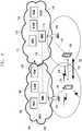
- FIG. 1illustrates an example of an architecture for EPC network-based D2D communication.
- Evolved packet core 1 (EPC 1) 103includes a home subscriber server (HSS) 105, a serving gateway (S-GW) 106, a packet data network gateway (PDN-GW; P-GW) 107, and a mobility management entity (MME) 104.
- UE 1 101is connected to the EPC 1 103 via evolved node B 1 (eNB1) 102.
- EPC2 114includes an HSS 111, an S-GW 112, a P-GW 113, and an MME 110.
- UE2 109is connected to the EPC2 114 via eNB2 109.
- the two MMEs 104, 110may be connected to each other 116, or the two EPC 103, 104 may share one MME with each other.
- the UE1 101 and the UE2 108are connected to the EPC1 103 and the EPC2 114 respectively. Both the UE1 101 and the UE2 108 can perform D2D communication. Each UE broadcasts an expression corresponding to itself over a discovery channel in order to allow neighboring UEs to receive (listen to) the expression. In this scenario, the UE1 101 broadcasts the UE's own expression 118.
- the UE2 108Upon receiving the broadcasted expression 118, the UE2 108 detects the ProSe ID (or other IDs) of the UE1 101 through the received expression 118.
- the UE2 108desires D2D communication with the UE1 101, the UE2 108 performs an operation for finding the UE1 101 in a cellular network.
- the UE2 108forwards information on the UE1 101, such as the ProSe ID, to the EPC2 114 via the eNB2 109 to thereby scan the UE1 101.
- Such a scan requestmay be forwarded to the EPC1 103 via the EPC2 114.
- the EPC1 103detects the ID of the UE1 101 in the EPC1 103.
- the EPC1 103informs the UE1 101 via the eNB1 102 that the D2D communication request is received from the UE2 108.
- the UE1 101accepts the D2D communication request, a notification of this acceptance is in turn forwarded to the UE2 108, and thus a data connection context and the like between the UE 1 101 and the UE2 108 are established.
- the UE2 108performs D2D RRC configuration with the UE1 101, and then performs D2D communication with the UE1 101.
- FIG. 2illustrates a structure of an expression according to an embodiment of the present disclosure.
- a UEmay generate and broadcast an expression, which has a structure as shown in FIG. 2 , over a discovery channel in order to receive permission for D2D communication and perform D2D communication.
- the expressionincludes an identification information field 201, an EPC information field 202, and a user preference field 203.
- a UEmay generate a ProSeID-containing identification information field 201 with a value that is produced using a ProSe ID allocated thereto, an authorization key (Auth key) received when obtaining authorization to use a D2D communication service, information open to other UEs (the public), and the like.
- the UEmay further generate an EPC information field 202 including information regarding an EPC network accessed by the UE and a user preference field 203 including information on preferences or situations of the UE's user.
- the expressionmay be configured to include the above fields 201, 202, 203.
- the identification information field 201may be generated using a hash function.
- a UE receiving the expressionmay generate identification information for ProSe IDs in the UE's friend list by using a hash function in the same manner.
- a ProSe ID corresponding to the same identification information as the received identification informationis the ProSe ID of a counterpart UE that has sent the expression received by the UE.
- the EPC information field 202 including information regarding an EPC network accessed by the UEmay include the ID of a group or network equipment accessed by the UE.
- the EPC information field 202may include an ECGI (E-UTRAN Cell Global Identifier), a TAI (Tracking Area Identity), a GUMMEI (Globally Unique MME Identity), or at least one or all of them.
- the EPC information field 202may include only a part of one of the above IDs.
- the EPC information field 202may include only a PLMN ID (Public Land Mobile Network Identifier).
- the EPC information field 202may also include the ID of the UE, allocated from an EPC network accessed by the UE, instead of the ID of a group or network equipment accessed by the UE.
- the EPC information field 202may include an ECGI and a CRNTI (Cell-Radio Network Temporary Identifier).
- the EPC information field 202may include at least one of an S-TMSI (SAE Temporary Mobile Subscriber Identity), a GUTI (Globally Unique Temporary UE Identity), and an IMSI (International Mobile Subscriber Identity).
- the EPC information field 202may include only a part of one of the above IDs.
- the EPC information field 202 including information regarding an EPC network accessed by the UE and the user preference field 203 including information on the UE's usermay be encrypted using an encryption key shared through an authorization procedure and the like.
- the authorization procedurewill be described below in detail in connection with step 356 in FIG. 3a or step 456 in FIG. 4a .
- the EPC information field 202 including information regarding an EPC network accessed by the UEincludes the ID of the UE, allocated from the EPC network accessed by the UE, a different method may be used for security.
- the part corresponding to the ID of the UE, excluding the ID of a group or network equipment accessed by the UE, for example, the M-TMSI part excluding the GUMMEI part in a GUTImay be encrypted or may be formed to include an authorization code.
- an encryption key(e.g., NAS security key, etc.), which is shared between the UE and the EPC network in order to allow the UE to access the EPC network, may be used.
- an encryption keye.g., NAS security key, etc.
- security or integrity for the contents included in the EPC information field 202can be checked.
- a descriptionwill be given of a procedure in which a UE accesses an EPC network to obtain authorization for a D2D communication service, generates an expression as described in the above embodiment of the present disclosure, detects the ProSe ID of a counterpart UE by making reference to the expression received from the counterpart UE, and acquires the cellular network ID of the counterpart UE, corresponding to the ProSe ID, to paging the counterpart UE and establish a data connection with the counterpart UE through the cellular network.
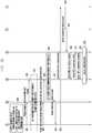
- FIGs. 3a and 3billustrate a D2D communication procedure according to an embodiment of the present disclosure.
- FIGs 3a and 3bwill be collectively referred to as “ FIG. 3 ".
- the embodiment of FIG. 3relates to a case where the EPC information field 202 of an expression includes the ID of a group or network equipment.
- UE1 320 and UE2 330access EPC1 300 and EPC2 350 respectively, obtain ProSe authorization, and generate an expression, so the following description will be given in conjunction with the procedure performed by the UE2 330.
- the UE2 330sends an attach request message to the EPC2 network 350 via the eNB2 340.
- the attach request messageincludes a ProSe capability indication indicating that the UE 330 supports D2D communication.
- step 353authorization for the UE2 330 is performed based on subscription information that the MME of the EPC2 350 receives from the HSS.
- the MMEmay receive ProSe_ID2 (the D2D ID of the UE2 330) together to store and manage mapping information between the UE ID in the EPC2 350 (EPC2 ID) and the ProSe_ID2.
- the mapping informationmay also be stored and managed by network equipment other than the MME. A method will be described below, in which the MME and the like acquires the mapping information in the EPC 2 network.
- step 354the EPC2 350 sends an attach accept message to the UE2 330.
- the attach accept messageincludes a ProSe permission notification indicating the result of performing the authorization for D2D communication, based on the subscription information.
- the UE2 330Upon receiving the attach accept message, in step 355, the UE2 330 sends an attach complete message to the EPC2 350.
- the network entry procedure of the UE2 330is completed by step 355.
- the UE2 330may perform configuration for D2D communication or authorization for a D2D communication service.
- the UE2 330generates an expression, as described above in the embodiment of FIG. 2 .
- the UE2 330may receive an Auth key that can be used when the UE2 330 generates an expression, and may also receive an encryption key for use in encrypting a part of the expression or an upper encryption key for generating the encryption key.
- step 351the UE1 320 enters the EPC1 network 300.
- Step 351corresponds to steps 352 to 356, so a detailed description thereof will be omitted here.
- step 357the UE1 320 generates an expression by using the UE's D2D ID, that is, ProSe_ID1, EPC information (EPC info_UE1), and the like.
- step 359the UE1 320 starts to broadcast the generated expression.
- the UE2 330receives the expression broadcasted by the UE1 320 to acquire the ProSe_ID1 from the received expression. That is, the UE2 330 may identify that the D2D ID of the transmitter UE of the corresponding expression is the ProSe_ID1. The UE2 330 acquires the ID of equipment accessed by the corresponding UE 320 in the EPC1 300, for example, a GUMMEI, from the received expression, and determines to perform D2D communication with the UE using the ProSe_ID1.
- the UE2 330does not yet know the EPC ID of the UE using the ProSe_ID1.
- the UE2 330sends a direct connection setup request message to the EPC2 350 via the eNB2 340 in order to establish a D2D connection with the ProSe_ID1 user.
- the direct connection setup request messagemay include information acquired by the UE2 330, that is, the ProSe_ID1 and EPC info_UE1. Further, the direct connection setup request message may also include the ProSe ID2 and the EPC info_UE2 of the UE2 330.
- the MME of the EPC2 350may check whether D2D communication between the ProSe_ID1 UE and the ProSe_ID2 UE existing in the UE's network is possible, based on service agreements between providers or other conditions.
- the EPC2 350forwards the direct connection setup request message to the EPC1 300 according to the EPC info_UE1.
- the EPC1 300detects the UE ID in the EPC1 300, that is, the EPC1 ID, mapped to the ProSe_ID1, by using the ProSE_ID1 and the EPC info_UE1 included in the forwarded direct connection setup request message.
- this scan stepmay be performed by the MME of the EPC1 300.
- the EPC1 300may check whether the corresponding UE, that is, the UE1 320, is able to perform D2D communication.
- step 365the MME of the EPC1 300 sends a paging request message to the eNB1 310.
- step 366the eNB1 310 sends a paging message to the UE1 320.
- step 367the UE1 320 performs a procedure for switching to an EMM-connected mode.
- the EPC1 300forwards the received direct connection setup request message to the UE1 320 in the EMM-connected mode via the eNB1 310.
- step 368the EPC1 300 sends an S1-AP message, which notifies the eNB1 310 that the direct connection setup is requested, to the eNB1 310, and upon receiving the S1-AP message, the eNB1 310 prepares resource allocation information and the like for the direct connection setup.
- the S1-AP message and the RRC reconfiguration message in steps 368 and 369may include the direct connection setup request message.
- the EPC1 300may also forward a message including information on the ProSe_ID2 and the EPC info_UE2, separately generated by the MME, to the UE1 320, instead of the direct connection setup request message.
- the UE1 320Upon receiving the direct connection setup request message, in step 370, the UE1 320 accepts the D2D communication request from the ProSe_ID2 UE. Accordingly, in step 371 and 372, the UE1 320 sends a message accepting the D2D communication request, that is, a direct connection setup accept message, to the EPC1 300 via the eNB1 310.
- the eNB1 310may use an S1-AP message in step 372 and procedures in steps 373 and 374 to forward the prepared resource allocation information and the like for the direct connection setup to the eNB2 340 accessed by the counterpart UE2 330.
- the eNB1 340may directly forward the prepared resource allocation information and the like for the direct connection setup to the counterpart eNB2 340.
- step 373the EPC 1 300 forwards the direct connection setup accept message to the EPC2 350.
- steps 374 and 375the EPC2 350 forwards the direct connection setup accept message to the UE2 330.
- step 374the EPC2 350 sends an S1-AP message, which notifies the eNB2 340 that the direct connection setup is accepted, to the eNB2 340, and the S1-AP message includes the resource allocation information and the like for the direct connection setup.
- the S1-AP message and the RRC reconfiguration message in steps 374 and 375may include the direct connection setup accept message.
- a direct connection radio bearer(D2D radio bearer) is set up using resources allocated by the eNB1 310 and the eNB2 340.
- the UE2 330directly sends a direct RRC connection request message to the UE1 320 in order to establish an RRC (Radio Resource Control) connection with the UE1 320.
- the UE1 320sends a direct RRC connection setup message to the UE2 330.
- the UE2 330sends a direct RRC connection complete message to the UE1 320.
- a radio beareris established.
- the UE1 320 and the UE2 330perform D2D communication through the established radio bearer.
- FIGs. 4a and 4billustrate a D2D communication procedure according to another embodiment of the present disclosure.
- FIGs 4a and 4bwill be collectively referred to as “ FIG. 4 ".
- the embodiment of FIG. 4relates to a case where the EPC information field 202 of an expression includes the ID of an UE, allocated from an EPC.
- UE1 420 and UE2 430access EPC1 400 and EPC2 450 respectively, obtain ProSe authorization, and generate an expression, so the following description will be given in conjunction with the procedure performed by the UE2 430.
- the UE2 430sends an attach request message to the EPC2 network 450 via the eNB2 440.
- the attach request messageincludes a ProSe capability indication indicating that the UE 430 supports D2D communication.
- step 453authorization for the UE2 430 is performed based on subscription information that the MME of the EPC2 450 receives from the HSS.
- the MMEmay receive ProSe_ID2 (the D2D ID of the UE2 430) together to store and manage mapping information between the UE ID in the EPC2 450 (EPC2 ID) and the ProSe_ID2.
- the mapping informationmay also be stored and managed by network equipment other than the MME. A method will be described below, in which the MME and the like acquires the mapping information in the EPC 2 network.
- step 454the EPC2 450 sends an attach accept message to the UE2 430.
- the attach accept messageincludes a ProSe permission notification indicating the result of performing the authorization for D2D communication, based on the subscription information.
- the UE2 430Upon receiving the attach accept message, in step 455, the UE2 430 sends an attach complete message to the EPC2 450.
- the network entry procedure of the UE2 430is completed by step 455.
- the UE2 430may perform configuration for D2D communication or authorization for a D2D communication service.
- the UE2 430generates an expression, as described above in the embodiment of FIG. 2 .
- the UE2 430may receive an Auth key that can be used when the UE2 430 generates an expression, and may also receive an encryption key for use in encrypting a part of the expression or an upper encryption key for generating the encryption key.
- step 451the UE1 420 enters the EPC1 network 400.
- Step 451corresponds to steps 452 to 456, so a detailed description thereof will be omitted here.
- step 457the UE1 420 generates an expression by using the UE's D2D ID, that is, ProSe_ID1, EPC info_UE1, and the like.
- step 459the UE1 420 starts to broadcast the generated expression.
- the UE2 430receives the expression broadcasted by the UE1 420 to acquire the ProSe_ID1 from the received expression. That is, the UE2 430 may identify that the D2D ID of the transmitter UE of the corresponding expression is the ProSe_ID1.
- the UE2 430acquires the ID of the corresponding UE 420 (EPC ID_UE1), allocated form the EPC1 400, for example, a GUTI, from the received expression, and determines to perform D2D communication with the UE using the ProSe_ID1.
- the UE2 430sends a direct connection setup request message to the EPC2 450 via the eNB2 440 in order to establish a D2D connection with the UE using the ProSe_ID1.
- the direct connection setup request messagemay include information acquired by the UE2 430, that is, the ProSe_ID1 and EPC ID_UE1, and may further include the UE's own ProSe ID2 and EPC ID_UE2.
- the MME of the EPC2 450may check whether D2D communication between the ProSe_ID1 UE and the ProSe_ID2 UE existing in MME's network is possible, based on service agreements between providers or other conditions.
- the EPC2 450forwards the direct connection setup request message to the EPC1 400 according to the EPC ID_UE1.
- the EPC1 400may also check whether the corresponding UE, that is, the UE1 420, is able to perform D2D communication, by using the EPC ID_UE1 included in the forwarded direct connection setup request message.
- step 465the MME of the EPC1 400 sends a paging request message to the eNB1 410.
- step 466the eNB1 410 sends a paging message to the UE1 420.
- step 467the UE1 420 performs a procedure 467 for switching to an EMM-connected mode.
- the EPC1 400forwards the received direct connection setup request message to the UE1 420 in the EMM-connected mode via the eNB1 410.
- step 468the EPC1 400 sends an S1-AP message, which notifies the eNB1 410 that the direct connection setup is requested, to the eNB1 410, and upon receiving the S1-AP message, the eNB1 410 prepares resource allocation information and the like for the direct connection setup.
- the S1-AP message and the RRC reconfiguration message in steps 468 and 469may include the direct connection setup request message.
- the EPC1 400may also forward a message including information on the ProSe_ID2 and the EPC ID_UE2, separately generated by the MME, to the UE1 420, instead of the direct connection setup request message.
- the UE1 420accepts the D2D communication request from the ProSe_ID2 UE.
- the UE1 420sends a message accepting the D2D communication request, that is, a direct connection setup accept message, to the EPC1 400 via the eNB1 410.
- the eNB1 410may use an S1-AP message in step 472 and procedures in steps 473 and 474 to forward the prepared resource allocation information and the like for the direct connection setup to the eNB2 440 accessed by the counterpart UE2 430.
- the eNB1 440may directly forward the prepared resource allocation information and the like for the direct connection setup to the counterpart eNB2 440.
- step 473the EPC 1 400 forwards the direct connection setup accept message to the EPC2 450.
- step 474the EPC2 450 sends an S1-AP message, which notifies the eNB2 440 that the direct connection setup is accepted, to the eNB2 440, and the S1-AP message includes the resource allocation information and the like for the direct connection setup.
- the S1-AP message and the RRC reconfiguration message in steps 474 and 475may include the direct connection setup request message.
- the EPC2 450forwards the direct connection setup accept message to the UE2 430.
- the EPC2 450sends an S1-AP message, which notifies the eNB2 440 that the direct connection setup is accepted, to the eNB2 440, and the S1-AP message includes the resource allocation information and the like for the direct connection setup.
- the S1-AP message and the RRC reconfiguration message in steps 474 and 475may include the direct connection setup accept message.
- a direct connection radio bearer(D2D radio bearer) is set up using resources allocated by the eNB1 410 and the eNB2 440.
- the UE2 430directly sends a direct RRC connection request message to the UE1 420 in order to establish an RRC (Radio Resource Control) connection with the UE1 420.
- the UE1 420sends a direct RRC connection setup message to the UE2 430.
- the UE2 430sends a direct RRC connection complete message to the UE1 420.
- a radio beareris established.
- the UE1 420 and the UE2 430perform D2D communication through the established radio bearer.
- a procedurewill be discussed in detail, in which a ProSe ID is transmitted to the EPC equipment (e.g., MME) of an EPC network, which is in charge of mapping between the ProSe ID and an ID allocated from the EPC network (EPC ID).
- EPC equipmente.g., MME
- EPC IDan ID allocated from the EPC network
- the ProSe ID informationmay be transferred to the MME while the MME sends updated location information to the HSS and receives subscription information for a UE from the HSS in the process of network entry of the UE, as described above in step 353 of FIG. 3 and step 453 of FIG. 4 .
- a ProSe IDmay be transmitted in such a manner that the HSS allocates the ProSe ID pre-stored therein to the EPC equipment in charge of the mapping, for example, the MME.
- FIG. 5illustrates a ProSe ID forwarding procedure according to an embodiment of the present disclosure.
- the eNB 510is located between the UE 500 and the EPC 520.
- the EPC 520may include, for example, an MME, an S-GW, a P-GW, an HSS, and the like.
- the UE 500accesses the EPC network.
- ProSe configuration and ProSe authorizationare performed.
- the UE 500acquires a ProSe ID.
- the UE 500sends a separate NAS (Network Access Stratum) message, that is, a ProSeID registration request message, to the EPC 520.
- the ProSeID registration request messageincludes the acquired ProSe ID.
- the EPC 520sends a ProSeID registration complete message to the UE 500 in response to the ProSeID registration request message.
- the ProSeID registration complete messageincludes the ProSe ID.
- the EPC 520forwards the received ProSe ID to the EPC equipment (e.g., MME) in charge of mapping between the ProSe ID and the ID allocated to the UE 500 from the EPC 520, and the EPC equipment stores the mapping relation between the forwarded ProSe ID and the ID allocated to the UE 500 from the EPC 520. That is, the EPC equipment correlates the ProSe ID and the ID (EPC ID) allocated to the UE 500 from the EPC 520, and stores the correlated ProSe ID and EPC ID.
- EPC equipmente.g., MME
- FIG. 6illustrates a ProSe ID forwarding procedure according to another embodiment of the present disclosure.
- the eNB 610is located between the UE 600 and the EPC 620.
- the EPC 620may include, for example, an MME, an S-GW, a P-GW, an HSS, and the like.
- the UE 600sends an attach request message to the EPC 620.
- the attach request messageincludes a ProSe capability indication.
- the EPC 620sends an attach accept message to the UE 600 in response to the attach request message.
- the UE 600determines if the UE 600 has an effective ProSe_ID.
- the UE 600sends an attach complete message to the EPC 620.
- the UE 600If the UE 600 already possesses an effective ProSe_ID, then the UE 600 sends an attach complete message including the effective ProSe_ID possessed by the UE 600.
- the ProSe_IDis forwarded to the EPC equipment (e.g., MME) of the EPC 620, which is in charge of mapping the ProSe_ID and the ID allocated to the EPC network (EPC ID).
- the EPC equipmentstores the mapping relation between the forwarded ProSe ID and the EPC ID. That is, the EPC equipment correlates the ProSe ID and the ID (EPC ID) allocated to the UE 500 from the EPC 520, and stores the correlated ProSe ID and EPC ID.
- Apparatuses used in embodiments of the present disclosuremay include a communication module and a controller respectively.
- the communication module of each UE, eNB, and entity of an EPCtransmits and receives signals in order to perform operations according to any one of the above embodiments of the present disclosure.
- the controller of each UE, eNB, and entity of an EPCcontrols each apparatus to be operated according to any one of the above embodiments of the present disclosure.
Landscapes
- Engineering & Computer Science (AREA)
- Computer Networks & Wireless Communication (AREA)
- Signal Processing (AREA)
- Databases & Information Systems (AREA)
- Mobile Radio Communication Systems (AREA)
Description
- At least of some embodiments of the present disclosure relate to a wireless cellular communication system-based device-to-device (D2D) communication.
- D2D communication refers to a communication mode between a pair of user equipments (UEs) that enables a UE to directly communicate and exchange data with a neighboring UE without the help of a cellular network, and each UE for D2D communication (hereinafter referred to as "D2D UE") broadcasts the UE's own information in order to inform other UEs of information on itself. A UE's own information used to inform other UEs of information on itself may include, for example, the identifier (ID) of the UE or the ID of UE's user (hereinafter referred to as "proximity service ID", "ProSe ID", or "D2D ID"). In addition, a UE acquires information on counterpart UEs through expressions received from neighboring UEs, and attempts to perform D2D communication when discovering a counterpart UE of interest from this information.
- Communication providers try to make a profit by providing D2D communication by using their underused licensed spectra or using unallocated radio resources in cellular networks and the like. Thus, they are seeking a way to provide D2D communication and control D2D services, based on a cellular network.
- Therefore, there is a need for a way to detect an ID, allocated in a cellular network (e.g., GUTI (Globally Unique Temporary UE Identity), from the ID of a UE or the ID of a UE's user (e.g., ProSe ID), used in D2D communication, in order to control paging and the like of the corresponding UE in the cellular network.
- HUAWEI ET AL: "Architecture Consideration for Proximity Services with infrastructure", 3GPP DRAFT; S2-130122, 3RD GENERATION PARTNERSHIP PROJECT (3GPP), MOBILE COMPETENCE CENTRE ; 650, ROUTE DES LUCIOLES ; F-06921 SOPHIA-ANTIPOLIS CEDEX; FRANCE, vol. SA WG2, no. Prague, Czech Republic; 20130128 - 20130201 22 January 2013 (2013-01-22), discloses considerations on system architecture enhancement for providing proximity services with infrastructure support.
- Any occurrence of the term "embodiment" in the description has to be considered as an "aspect of the invention", the invention being defined in the appended independent claims.
- To address the above-discussed deficiencies, it is a primary object to provide a device-to-device (D2D) communication apparatus and method capable of efficiently performing D2D communication.
- According to an embodiment of the present disclosure, there is provided a method of performing a device-to-device (D2D) communication by a user equipment (UE), the method including: acquiring a proximity service identifier (ProSe ID) of the UE or the UE's user, which is used in the D2D communication; generating an expression by using the ProSe ID; broadcasting the generated expression; receiving a direct D2D connection request message from another UE over a core network; sending a direct connection accept message in response to the direct D2D connection request message; and performing the D2D communication with another UE.
- According to an embodiment of the present disclosure, there is provided a method of performing a device-to-device (D2D) communication by a user equipment (UE), the method including: receiving an expression broadcasted by another UE; acquiring a proximity service identifier (ProSe ID) of another UE or another UE's user; sending a direct D2D connection request message to another UE over a core network; receiving a direct connection accept message in response to the direct D2D connection request message; and performing the D2D communication with another UE by using the ProSe ID.
- According to an embodiment of the present disclosure, there is provided a method of supporting device-to-device (D2D) communication by a communication entity, the method including: receiving a direct connection request message, requesting a connection with a second user equipment (UE), from a first UE; sending a paging message to the second UE; forwarding the direct connection request message to the second UE after the second UE is in a connected state; receiving a direct connection accept message from the second UE in response to the direct connection request message; and forwarding the direct connection accept message to the first UE.
- According to at least some embodiments of the present disclosure, D2D communication can be efficiently performed.
- Before undertaking the DETAILED DESCRIPTION below, it may be advantageous to set forth definitions of certain words and phrases used throughout this patent document: the terms "include" and "comprise," as well as derivatives thereof, mean inclusion without limitation; the term "or," is inclusive, meaning and/or; the phrases "associated with" and "associated therewith," as well as derivatives thereof, may mean to include, be included within, interconnect with, contain, be contained within, connect to or with, couple to or with, be communicable with, cooperate with, interleave, juxtapose, be proximate to, be bound to or with, have, have a property of, or the like; and the term "controller" means any device, system or part thereof that controls at least one operation, such a device may be implemented in hardware, firmware or software, or some combination of at least two of the same. It should be noted that the functionality associated with any particular controller may be centralized or distributed, whether locally or remotely. Definitions for certain words and phrases are provided throughout this patent document, those of ordinary skill in the art should understand that in many, if not most instances, such definitions apply to prior, as well as future uses of such defined words and phrases.
- For a more complete understanding of the present disclosure and its advantages, reference is now made to the following description taken in conjunction with the accompanying drawings, in which like reference numerals represent like parts:
FIG. 1 illustrates an example of an architecture for EPC network-based D2D communication;FIG. 2 illustrates a structure of an expression according to an embodiment of the present disclosure;FIGs. 3a and3b are flow diagrams illustrating a D2D communication procedure according to an embodiment of the present disclosure;FIGs. 4a and4b are flow diagrams illustrating a D2D communication procedure according to another embodiment of the present disclosure;FIG. 5 is a flow diagram illustrating a ProSe ID forwarding procedure according to an embodiment of the present disclosure; andFIG. 6 is a flow diagram illustrating a ProSe ID forwarding procedure according to another embodiment of the present disclosure.FIGURES 1 through 6 , discussed below, and the various embodiments used to describe the principles of the present disclosure in this patent document are by way of illustration only and should not be construed in any way to limit the scope of the disclosure. Those skilled in the art will understand that the principles of the present disclosure may be implemented in any suitably arranged system or device. Hereinafter, embodiments of the present disclosure will be described in detail with reference to the accompanying drawings. In the following description of the present disclosure, a detailed description of known functions and configurations incorporated herein will be omitted when it may make the subject matter of the present disclosure rather unclear. Further, although an evolved packet core (EPC) network, that is, an LTE network, is described herein as an example of a cellular network, embodiments of the present disclosure may also be applied to wireless data communication networks other than the LTE network.- At least some embodiments of the present disclosure relate to a method and apparatus in which a user equipment (hereinafter referred to as "UE") discovers another counterpart UE located in a short range, establishes a data connection with the counterpart UE by paging the counterpart UE in order to perform D2D communication with the counterpart UE, and then performs D2D communication with the counterpart UE. Further, at least some embodiments of the present disclosure relate to a method and apparatus in which a UE configures the UE's own expression that the UE broadcasts in order to find a counterpart UE through a cellular network. Further, at least some embodiments of the present disclosure relate to a method and apparatus in which when a UE attempts to page a counterpart UE through a cellular network or establish a data connection to a counterpart UE in order to perform D2D communication with the counterpart UE, the UE controls authorization including whether D2D communication is possible. Further, at least some embodiments of the present disclosure relate to a method and apparatus in which a UE forwards the UE's ID used in D2D communication (proximity service ID, ProSe ID, or D2D ID) to a cellular network.
- In the following embodiments of the present disclosure, a method of performing EPC network-based D2D communication will be described in detail. In an embodiment of the present disclosure, although an EPC network will be mainly described by way of example, any other type of core of a cellular-based network may replace the EPC.
FIG. 1 illustrates an example of an architecture for EPC network-based D2D communication. Evolved packet core 1 (EPC 1) 103 includes a home subscriber server (HSS) 105, a serving gateway (S-GW) 106, a packet data network gateway (PDN-GW; P-GW) 107, and a mobility management entity (MME) 104. UE 1 101 is connected to theEPC 1 103 via evolved node B 1 (eNB1) 102.EPC2 114 includes anHSS 111, an S-GW 112, a P-GW 113, and anMME 110. UE2 109 is connected to theEPC2 114 via eNB2 109. The twoMMEs EPC - The UE1 101 and the UE2 108 are connected to the
EPC1 103 and theEPC2 114 respectively. Both the UE1 101 and the UE2 108 can perform D2D communication. Each UE broadcasts an expression corresponding to itself over a discovery channel in order to allow neighboring UEs to receive (listen to) the expression. In this scenario, the UE1 101 broadcasts the UE'sown expression 118. - Upon receiving the
broadcasted expression 118, theUE2 108 detects the ProSe ID (or other IDs) of the UE1 101 through thereceived expression 118. When theUE2 108 desires D2D communication with theUE1 101, the UE2 108 performs an operation for finding theUE1 101 in a cellular network. As an example, the UE2 108 forwards information on the UE1 101, such as the ProSe ID, to theEPC2 114 via theeNB2 109 to thereby scan the UE1 101. Such a scan request may be forwarded to theEPC1 103 via theEPC2 114. TheEPC1 103 detects the ID of the UE1 101 in theEPC1 103. TheEPC1 103 informs the UE1 101 via the eNB1 102 that the D2D communication request is received from theUE2 108. When the UE1 101 accepts the D2D communication request, a notification of this acceptance is in turn forwarded to theUE2 108, and thus a data connection context and the like between the UE 1 101 and the UE2 108 are established. Based on this, theUE2 108 performs D2D RRC configuration with theUE1 101, and then performs D2D communication with theUE1 101. FIG. 2 illustrates a structure of an expression according to an embodiment of the present disclosure.- According to an embodiment of the present disclosure, a UE may generate and broadcast an expression, which has a structure as shown in
FIG. 2 , over a discovery channel in order to receive permission for D2D communication and perform D2D communication. - Referring to
FIG. 2 , the expression includes anidentification information field 201, anEPC information field 202, and auser preference field 203. - A UE may generate a ProSeID-containing
identification information field 201 with a value that is produced using a ProSe ID allocated thereto, an authorization key (Auth key) received when obtaining authorization to use a D2D communication service, information open to other UEs (the public), and the like. The UE may further generate anEPC information field 202 including information regarding an EPC network accessed by the UE and auser preference field 203 including information on preferences or situations of the UE's user. The expression may be configured to include theabove fields identification information field 201 may be generated using a hash function. In such a case, a UE receiving the expression may generate identification information for ProSe IDs in the UE's friend list by using a hash function in the same manner. A ProSe ID corresponding to the same identification information as the received identification information is the ProSe ID of a counterpart UE that has sent the expression received by the UE. - The
EPC information field 202 including information regarding an EPC network accessed by the UE may include the ID of a group or network equipment accessed by the UE. As an example, theEPC information field 202 may include an ECGI (E-UTRAN Cell Global Identifier), a TAI (Tracking Area Identity), a GUMMEI (Globally Unique MME Identity), or at least one or all of them. Alternatively, theEPC information field 202 may include only a part of one of the above IDs. As an example, theEPC information field 202 may include only a PLMN ID (Public Land Mobile Network Identifier). - However, the
EPC information field 202 may also include the ID of the UE, allocated from an EPC network accessed by the UE, instead of the ID of a group or network equipment accessed by the UE. As an example, theEPC information field 202 may include an ECGI and a CRNTI (Cell-Radio Network Temporary Identifier). Alternatively, theEPC information field 202 may include at least one of an S-TMSI (SAE Temporary Mobile Subscriber Identity), a GUTI (Globally Unique Temporary UE Identity), and an IMSI (International Mobile Subscriber Identity). Alternatively, theEPC information field 202 may include only a part of one of the above IDs. - For the purpose of security, the
EPC information field 202 including information regarding an EPC network accessed by the UE and theuser preference field 203 including information on the UE's user may be encrypted using an encryption key shared through an authorization procedure and the like. The authorization procedure will be described below in detail in connection withstep 356 inFIG. 3a or step 456 inFIG. 4a . - Further, when the
EPC information field 202 including information regarding an EPC network accessed by the UE includes the ID of the UE, allocated from the EPC network accessed by the UE, a different method may be used for security. In theEPC information field 202 including information regarding an EPC network accessed by the UE, the part corresponding to the ID of the UE, excluding the ID of a group or network equipment accessed by the UE, for example, the M-TMSI part excluding the GUMMEI part in a GUTI, may be encrypted or may be formed to include an authorization code. For the encryption procedure or to generate the authorization code, an encryption key (e.g., NAS security key, etc.), which is shared between the UE and the EPC network in order to allow the UE to access the EPC network, may be used. By using the encrypted information or the authorization key, security or integrity for the contents included in theEPC information field 202 can be checked. - As another embodiment of the present disclosure, a description will be given of a procedure in which a UE accesses an EPC network to obtain authorization for a D2D communication service, generates an expression as described in the above embodiment of the present disclosure, detects the ProSe ID of a counterpart UE by making reference to the expression received from the counterpart UE, and acquires the cellular network ID of the counterpart UE, corresponding to the ProSe ID, to paging the counterpart UE and establish a data connection with the counterpart UE through the cellular network.
FIGs. 3a and3b illustrate a D2D communication procedure according to an embodiment of the present disclosure. Hereinafter,FIGs 3a and3b will be collectively referred to as "FIG. 3 ". The embodiment ofFIG. 3 relates to a case where theEPC information field 202 of an expression includes the ID of a group or network equipment.- Referring to
FIGs. 3a and3b , through the same procedure,UE1 320 andUE2 330access EPC1 300 andEPC2 350 respectively, obtain ProSe authorization, and generate an expression, so the following description will be given in conjunction with the procedure performed by theUE2 330. - In
step 352, in order to access theEPC2 350, theUE2 330 sends an attach request message to theEPC2 network 350 via theeNB2 340. The attach request message includes a ProSe capability indication indicating that theUE 330 supports D2D communication. - In
step 353, authorization for theUE2 330 is performed based on subscription information that the MME of theEPC2 350 receives from the HSS. In this step, the MME may receive ProSe_ID2 (the D2D ID of the UE2 330) together to store and manage mapping information between the UE ID in the EPC2 350 (EPC2 ID) and the ProSe_ID2. Of course, the mapping information may also be stored and managed by network equipment other than the MME. A method will be described below, in which the MME and the like acquires the mapping information in the EPC 2 network. - When the authorization in
step 353 is successful, instep 354, theEPC2 350 sends an attach accept message to theUE2 330. The attach accept message includes a ProSe permission notification indicating the result of performing the authorization for D2D communication, based on the subscription information. Upon receiving the attach accept message, instep 355, theUE2 330 sends an attach complete message to theEPC2 350. The network entry procedure of theUE2 330 is completed bystep 355. Instep 356, theUE2 330 may perform configuration for D2D communication or authorization for a D2D communication service. - Further, in
step 358, theUE2 330 generates an expression, as described above in the embodiment ofFIG. 2 . In the process of the authorization for a D2D communication service, theUE2 330 may receive an Auth key that can be used when theUE2 330 generates an expression, and may also receive an encryption key for use in encrypting a part of the expression or an upper encryption key for generating the encryption key. - In
step 351, theUE1 320 enters theEPC1 network 300. Step 351 corresponds tosteps 352 to 356, so a detailed description thereof will be omitted here. - In
step 357, theUE1 320 generates an expression by using the UE's D2D ID, that is, ProSe_ID1, EPC information (EPC info_UE1), and the like. Instep 359, theUE1 320 starts to broadcast the generated expression. - In
step 360, theUE2 330 receives the expression broadcasted by theUE1 320 to acquire the ProSe_ID1 from the received expression. That is, theUE2 330 may identify that the D2D ID of the transmitter UE of the corresponding expression is the ProSe_ID1. TheUE2 330 acquires the ID of equipment accessed by the correspondingUE 320 in theEPC1 300, for example, a GUMMEI, from the received expression, and determines to perform D2D communication with the UE using the ProSe_ID1. - The
UE2 330 does not yet know the EPC ID of the UE using the ProSe_ID1. Thus, instep 361, theUE2 330 sends a direct connection setup request message to theEPC2 350 via theeNB2 340 in order to establish a D2D connection with the ProSe_ID1 user. The direct connection setup request message may include information acquired by theUE2 330, that is, the ProSe_ID1 and EPC info_UE1. Further, the direct connection setup request message may also include the ProSe ID2 and the EPC info_UE2 of theUE2 330. Instep 362, using the EPC info_UE1, the MME of theEPC2 350 may check whether D2D communication between the ProSe_ID1 UE and the ProSe_ID2 UE existing in the UE's network is possible, based on service agreements between providers or other conditions. - When it is determined that D2D communication is possible, in
step 363, theEPC2 350 forwards the direct connection setup request message to theEPC1 300 according to the EPC info_UE1. Instep 364, theEPC1 300 detects the UE ID in theEPC1 300, that is, the EPC1 ID, mapped to the ProSe_ID1, by using the ProSE_ID1 and the EPC info_UE1 included in the forwarded direct connection setup request message. As an example, this scan step may be performed by the MME of theEPC1 300. - Further, based on the EPC1 ID corresponding to the acquired ProSe_ID1, the
EPC1 300 may check whether the corresponding UE, that is, theUE1 320, is able to perform D2D communication. - When it is checked that the
UE1 320 is in an EMM-idle mode, instep 365, the MME of theEPC1 300 sends a paging request message to theeNB1 310. Instep 366, theeNB1 310 sends a paging message to theUE1 320. Subsequently, instep 367, theUE1 320 performs a procedure for switching to an EMM-connected mode. - Next, in
steps EPC1 300 forwards the received direct connection setup request message to theUE1 320 in the EMM-connected mode via theeNB1 310. - In
step 368, theEPC1 300 sends an S1-AP message, which notifies theeNB1 310 that the direct connection setup is requested, to theeNB1 310, and upon receiving the S1-AP message, theeNB1 310 prepares resource allocation information and the like for the direct connection setup. The S1-AP message and the RRC reconfiguration message insteps - The
EPC1 300 may also forward a message including information on the ProSe_ID2 and the EPC info_UE2, separately generated by the MME, to theUE1 320, instead of the direct connection setup request message. Upon receiving the direct connection setup request message, instep 370, theUE1 320 accepts the D2D communication request from the ProSe_ID2 UE. Accordingly, instep UE1 320 sends a message accepting the D2D communication request, that is, a direct connection setup accept message, to theEPC1 300 via theeNB1 310. - Upon receiving an RRC reconfiguration message in
step 371, theeNB1 310 may use an S1-AP message instep 372 and procedures insteps eNB2 340 accessed by thecounterpart UE2 330. Alternatively, according to a modified embodiment of the present disclosure, theeNB1 340 may directly forward the prepared resource allocation information and the like for the direct connection setup to thecounterpart eNB2 340. - In
step 373, theEPC 1 300 forwards the direct connection setup accept message to theEPC2 350. Insteps EPC2 350 forwards the direct connection setup accept message to theUE2 330. - In
step 374, theEPC2 350 sends an S1-AP message, which notifies theeNB2 340 that the direct connection setup is accepted, to theeNB2 340, and the S1-AP message includes the resource allocation information and the like for the direct connection setup. - The S1-AP message and the RRC reconfiguration message in
steps - Subsequently, a direct connection radio bearer (D2D radio bearer) is set up using resources allocated by the
eNB1 310 and theeNB2 340. As an example, instep 376, theUE2 330 directly sends a direct RRC connection request message to theUE1 320 in order to establish an RRC (Radio Resource Control) connection with theUE1 320. Instep 377, theUE1 320 sends a direct RRC connection setup message to theUE2 330. Instep 378, theUE2 330 sends a direct RRC connection complete message to theUE1 320. Accordingly, a radio bearer is established. Instep 379, theUE1 320 and theUE2 330 perform D2D communication through the established radio bearer. FIGs. 4a and4b illustrate a D2D communication procedure according to another embodiment of the present disclosure. Hereinafter,FIGs 4a and4b will be collectively referred to as "FIG. 4 ". In particular, the embodiment ofFIG. 4 relates to a case where theEPC information field 202 of an expression includes the ID of an UE, allocated from an EPC.- Referring to
FIGs. 4a and4b , through the same procedure,UE1 420 andUE2 430access EPC1 400 andEPC2 450 respectively, obtain ProSe authorization, and generate an expression, so the following description will be given in conjunction with the procedure performed by theUE2 430. - In
step 452, in order to access theEPC2 450, theUE2 430 sends an attach request message to theEPC2 network 450 via theeNB2 440. The attach request message includes a ProSe capability indication indicating that theUE 430 supports D2D communication. - In
step 453, authorization for theUE2 430 is performed based on subscription information that the MME of theEPC2 450 receives from the HSS. In this step, the MME may receive ProSe_ID2 (the D2D ID of the UE2 430) together to store and manage mapping information between the UE ID in the EPC2 450 (EPC2 ID) and the ProSe_ID2. Of course, the mapping information may also be stored and managed by network equipment other than the MME. A method will be described below, in which the MME and the like acquires the mapping information in the EPC 2 network. - When the authorization in
step 453 is successful, instep 454, theEPC2 450 sends an attach accept message to theUE2 430. The attach accept message includes a ProSe permission notification indicating the result of performing the authorization for D2D communication, based on the subscription information. Upon receiving the attach accept message, instep 455, theUE2 430 sends an attach complete message to theEPC2 450. The network entry procedure of theUE2 430 is completed bystep 455. Instep 456, theUE2 430 may perform configuration for D2D communication or authorization for a D2D communication service. - Further, in
step 458, theUE2 430 generates an expression, as described above in the embodiment ofFIG. 2 . In the process of the authorization for a D2D communication service, theUE2 430 may receive an Auth key that can be used when theUE2 430 generates an expression, and may also receive an encryption key for use in encrypting a part of the expression or an upper encryption key for generating the encryption key. - In
step 451, theUE1 420 enters theEPC1 network 400. Step 451 corresponds tosteps 452 to 456, so a detailed description thereof will be omitted here. - In
step 457, theUE1 420 generates an expression by using the UE's D2D ID, that is, ProSe_ID1, EPC info_UE1, and the like. Instep 459, theUE1 420 starts to broadcast the generated expression. - In
step 460, theUE2 430 receives the expression broadcasted by theUE1 420 to acquire the ProSe_ID1 from the received expression. That is, theUE2 430 may identify that the D2D ID of the transmitter UE of the corresponding expression is the ProSe_ID1. TheUE2 430 acquires the ID of the corresponding UE 420 (EPC ID_UE1), allocated form theEPC1 400, for example, a GUTI, from the received expression, and determines to perform D2D communication with the UE using the ProSe_ID1. - In
step 461, theUE2 430 sends a direct connection setup request message to theEPC2 450 via theeNB2 440 in order to establish a D2D connection with the UE using the ProSe_ID1. The direct connection setup request message may include information acquired by theUE2 430, that is, the ProSe_ID1 and EPC ID_UE1, and may further include the UE's own ProSe ID2 and EPC ID_UE2. Instep 462, using the EPC ID_UE1, the MME of theEPC2 450 may check whether D2D communication between the ProSe_ID1 UE and the ProSe_ID2 UE existing in MME's network is possible, based on service agreements between providers or other conditions. - When it is determined that D2D communication is possible, in
step 463, theEPC2 450 forwards the direct connection setup request message to theEPC1 400 according to the EPC ID_UE1. Instep 464, theEPC1 400 may also check whether the corresponding UE, that is, theUE1 420, is able to perform D2D communication, by using the EPC ID_UE1 included in the forwarded direct connection setup request message. - When it is checked that the
UE1 420 is in an EMM-idle mode, instep 465, the MME of theEPC1 400 sends a paging request message to theeNB1 410. Instep 466, theeNB1 410 sends a paging message to theUE1 420. Instep 467, theUE1 420 performs aprocedure 467 for switching to an EMM-connected mode. - Subsequently, in
steps EPC1 400 forwards the received direct connection setup request message to theUE1 420 in the EMM-connected mode via theeNB1 410. - In
step 468, theEPC1 400 sends an S1-AP message, which notifies theeNB1 410 that the direct connection setup is requested, to theeNB1 410, and upon receiving the S1-AP message, theeNB1 410 prepares resource allocation information and the like for the direct connection setup. The S1-AP message and the RRC reconfiguration message insteps - The
EPC1 400 may also forward a message including information on the ProSe_ID2 and the EPC ID_UE2, separately generated by the MME, to theUE1 420, instead of the direct connection setup request message. Upon receiving the direct connection setup request message, instep 470, theUE1 420 accepts the D2D communication request from the ProSe_ID2 UE. Accordingly, instep UE1 420 sends a message accepting the D2D communication request, that is, a direct connection setup accept message, to theEPC1 400 via theeNB1 410. - Upon receiving an RRC reconfiguration message in
step 471, theeNB1 410 may use an S1-AP message instep 472 and procedures insteps eNB2 440 accessed by thecounterpart UE2 430. Alternatively, according to a modified embodiment of the present disclosure, upon receiving the RRC reconfiguration message instep 471, theeNB1 440 may directly forward the prepared resource allocation information and the like for the direct connection setup to thecounterpart eNB2 440. - In
step 473, theEPC 1 400 forwards the direct connection setup accept message to theEPC2 450. Instep 474, theEPC2 450 sends an S1-AP message, which notifies theeNB2 440 that the direct connection setup is accepted, to theeNB2 440, and the S1-AP message includes the resource allocation information and the like for the direct connection setup. - The S1-AP message and the RRC reconfiguration message in
steps - In
steps EPC2 450 forwards the direct connection setup accept message to theUE2 430. Instep 474, theEPC2 450 sends an S1-AP message, which notifies theeNB2 440 that the direct connection setup is accepted, to theeNB2 440, and the S1-AP message includes the resource allocation information and the like for the direct connection setup. - The S1-AP message and the RRC reconfiguration message in
steps - Subsequently, a direct connection radio bearer (D2D radio bearer) is set up using resources allocated by the
eNB1 410 and theeNB2 440. As an example, instep 476, theUE2 430 directly sends a direct RRC connection request message to theUE1 420 in order to establish an RRC (Radio Resource Control) connection with theUE1 420. In step 477, theUE1 420 sends a direct RRC connection setup message to theUE2 430. Instep 478, theUE2 430 sends a direct RRC connection complete message to theUE1 420. Accordingly, a radio bearer is established. Instep 479, theUE1 420 and theUE2 430 perform D2D communication through the established radio bearer. - Hereinafter, as another embodiment of the present disclosure, a procedure will be discussed in detail, in which a ProSe ID is transmitted to the EPC equipment (e.g., MME) of an EPC network, which is in charge of mapping between the ProSe ID and an ID allocated from the EPC network (EPC ID).
- The ProSe ID information may be transferred to the MME while the MME sends updated location information to the HSS and receives subscription information for a UE from the HSS in the process of network entry of the UE, as described above in
step 353 ofFIG. 3 and step 453 ofFIG. 4 . In such a case, a ProSe ID may be transmitted in such a manner that the HSS allocates the ProSe ID pre-stored therein to the EPC equipment in charge of the mapping, for example, the MME. FIG. 5 illustrates a ProSe ID forwarding procedure according to an embodiment of the present disclosure.- Referring to
FIG. 5 , theeNB 510 is located between theUE 500 and theEPC 520. TheEPC 520 may include, for example, an MME, an S-GW, a P-GW, an HSS, and the like. Instep 521, theUE 500 accesses the EPC network. Instep 522, ProSe configuration and ProSe authorization are performed. In the process of this, theUE 500 acquires a ProSe ID. Instep 523, theUE 500 sends a separate NAS (Network Access Stratum) message, that is, a ProSeID registration request message, to theEPC 520. The ProSeID registration request message includes the acquired ProSe ID. Instep 524, theEPC 520 sends a ProSeID registration complete message to theUE 500 in response to the ProSeID registration request message. The ProSeID registration complete message includes the ProSe ID. TheEPC 520 forwards the received ProSe ID to the EPC equipment (e.g., MME) in charge of mapping between the ProSe ID and the ID allocated to theUE 500 from theEPC 520, and the EPC equipment stores the mapping relation between the forwarded ProSe ID and the ID allocated to theUE 500 from theEPC 520. That is, the EPC equipment correlates the ProSe ID and the ID (EPC ID) allocated to theUE 500 from theEPC 520, and stores the correlated ProSe ID and EPC ID. FIG. 6 illustrates a ProSe ID forwarding procedure according to another embodiment of the present disclosure.- Referring to
FIG. 6 , theeNB 610 is located between theUE 600 and theEPC 620. TheEPC 620 may include, for example, an MME, an S-GW, a P-GW, an HSS, and the like. Instep 621, theUE 600 sends an attach request message to theEPC 620. The attach request message includes a ProSe capability indication. Instep 622, theEPC 620 sends an attach accept message to theUE 600 in response to the attach request message. In step 632, theUE 600 determines if theUE 600 has an effective ProSe_ID. Instep 624, theUE 600 sends an attach complete message to theEPC 620. If theUE 600 already possesses an effective ProSe_ID, then theUE 600 sends an attach complete message including the effective ProSe_ID possessed by theUE 600. The ProSe_ID is forwarded to the EPC equipment (e.g., MME) of theEPC 620, which is in charge of mapping the ProSe_ID and the ID allocated to the EPC network (EPC ID). Instep 625, the EPC equipment stores the mapping relation between the forwarded ProSe ID and the EPC ID. That is, the EPC equipment correlates the ProSe ID and the ID (EPC ID) allocated to theUE 500 from theEPC 520, and stores the correlated ProSe ID and EPC ID. - Apparatuses used in embodiments of the present disclosure, that is, UEs, eNBs, and constituent entities of EPCs, for example, MMEs, s-GWs, P-GWs, and HSSs, may include a communication module and a controller respectively. The communication module of each UE, eNB, and entity of an EPC transmits and receives signals in order to perform operations according to any one of the above embodiments of the present disclosure. The controller of each UE, eNB, and entity of an EPC controls each apparatus to be operated according to any one of the above embodiments of the present disclosure.
- Although the present disclosure has been described with an exemplary embodiment, various changes and modifications may be suggested to one skilled in the art. It is intended that the present disclosure encompass such changes and modifications as fall within the scope of the appended claims.
Claims (15)
- A method of performing a device-to-device, D2D, communication by a terminal, the method comprising:acquiring a proximity service identifier, ProSe ID, of the terminal, which is used in the D2D communication, from a first core network of the terminal (S351);generating an expression message including the ProSe ID of the terminal and an ID of the first core network (S357);broadcasting the generated expression message to at least one other terminal in a second core network;receiving from the first core network a direct connection request message from the at least one other terminal via the second core network, the direct connection request message including the ProSe ID of the terminal and the ID of the first core network (S363∼S369);transmitting a direct connection accept message to the at least one other terminal via the first core network in response to the direct connection request message (S371∼S372); andperforming the D2D communication with the at least one other terminal.
- The method of claim 1, wherein the expression includes an ID allocated to the terminal from the first core network.
- The method of claim 1 or 2, wherein the ID of the first core network stores a mapping relation between the ProSe ID of the terminal and the ID allocated to the terminal from the first core network.
- A method of performing a device-to-device, D2D, communication by a terminal, the method comprising:receiving an expression message broadcasted by at least one other terminal (S359);acquiring a proximity service identifier, ProSe ID, of the at least one other terminal and an ID of a first core network of the at least one other terminal from the expression message (S360);transmitting, to the at least one other terminal, a direct connection request message via a second core network of the terminal including the ProSe ID of the at least one other terminal and the ID of the first core network (S361∼S363);receiving, from the at least one other terminal and via the second core network, a direct connection accept message in response to the direct connection request message (S371∼S374); andperforming the D2D communication with the at least one other terminal using the ProSe ID of the at least one other terminal (S379).
- The method of claim 4, wherein the expression message includes an ID allocated to the at least one other terminal from the first core network.
- The method of claim 4 or 5, wherein the ID of the first core network stores a mapping relation between the ProSe ID of the at least one other terminal and the ID allocated to the at least one other terminal from the first core network.
- A method of supporting device-to-device, D2D, communication by a communication entity in a first core network, the method comprising:receiving, from a first terminal, a direct connection request message including a proximity service identifier, ProSe ID, of a second terminal, a ProSe ID of the first terminal and a ID of a second core network of the second terminal for requesting a connection with the second terminal (S361∼S363);transmitting, to the second terminal via a second core network of the second terminal, a paging message using the Prose ID of the second terminal and the identifier of the core network (S364∼366);forwarding, to the second terminal, via the second core network, the direct connection request message after the second terminal is in a connected state (S368∼S369);receiving, from the second terminal, via the second core network a direct connection accept message in response to the direct connection request message; (S371∼S372) andforwarding, to the first terminal, the direct connection accept message (S373∼S374).
- A terminal for performing a device-to-device, D2D, communication, the terminal comprising:a transmitter configured to transmit a signal to at least one other terminal;a receiver configured to receive a signal from at least one other terminal; anda controller configured to acquire a proximity service identifier, ProSe ID, of the terminal, which is used in the D2D communication, from a first core network of the terminal, to generate an expression message including the ProSe ID of the terminal and an ID of the first core network, to broadcast the generated expression message to at least one other terminal, to receive a direct connection request message from the at least one other terminal via a second core network of the second terminal, the request message including the ProSe ID of the terminal and the ID of the first core network, to transmit a direct connection accept message to the at least one other terminal via the first core network in response to the direct connection request message, and to perform the D2D communication with the at least one other terminal.
- The terminal of claim 8, wherein the expression includes an ID allocated to the terminal from the first core network.
- The terminal of claim 8 or 9, wherein the ID of the first core network stores a mapping relation between the ProSe ID of the terminal and the ID allocated to the terminal from the first core network.
- A terminal of performing a device-to-device, D2D, communication, the terminal comprising:a transmitter configured to transmit a signal to at least one other terminal;a receiver configured to receive a signal from at least one other terminal;a controller configured to control receive an expression message broadcasted by at least one other terminal, to acquire a proximity service identifier, ProSe ID, of the at least one other terminal and an ID of a first core network of the at least one other terminal from the expression message, and to transmit a direct connection request message to the at least one other terminal via a second core network of the terminal, the direct connection request message including the ProSe ID of the at least one other terminal and the ID of the first core network, to receive a direct connection accept message in response to the direct connection request message from the at least one other terminal, via the first core network and to perform the D2D communication with the at least one other terminal using the ProSe ID of the at least one other terminal.
- The terminal claim 11, wherein the expression message includes an ID allocated to the at least one other terminal from the first core network.
- The terminal of claim 11 or 12, wherein the ID of the first core network stores a mapping relation between the ProSe ID of the at least one other terminal and the ID allocated to the at least one other terminal from the first core network.
- A communication entity for to be used in a first core network, the communication entity supporting device-to-device, D2D, communication, the communication entity comprising:a transmitter configured to transmit a signal to at least one terminal;a receiver configured to receive a signal from at least one terminal;a controller configured to receive, from a first terminal, a direct connection request message including a proximity service identifier, ProSe ID, of a second terminal, a ProSe ID of the first terminal and a ID of a second core network of the second terminal for requesting a connection with the second terminal, to transmit, to the second terminal, via the second core network a paging message including the Prose ID of the second terminal and the ID of the second core network, to forward, to the second terminal, via the second core network the direct connection request message after the second terminal is in a connected state, to receive, from the second terminal, via the second core network a direct connection accept message in response to the direct connection request message, and to forward, to the first terminal, the direct connection accept message.
- The communication entity of claim 14, wherein the controller is configured to allocate an ID to the first terminal for inclusion in an expression message.
Applications Claiming Priority (2)
| Application Number | Priority Date | Filing Date | Title |
|---|---|---|---|
| KR20130009353 | 2013-01-28 | ||
| KR1020130083119AKR102112610B1 (en) | 2013-01-28 | 2013-07-15 | Method and apparatus for device to device communication |
Publications (2)
| Publication Number | Publication Date |
|---|---|
| EP2768272A1 EP2768272A1 (en) | 2014-08-20 |
| EP2768272B1true EP2768272B1 (en) | 2017-03-22 |
Family
ID=50031149
Family Applications (1)
| Application Number | Title | Priority Date | Filing Date |
|---|---|---|---|
| EP14152831.5AActiveEP2768272B1 (en) | 2013-01-28 | 2014-01-28 | Methods and apparatuses for device to device communication |
Country Status (3)
| Country | Link |
|---|---|
| US (1) | US9713182B2 (en) |
| EP (1) | EP2768272B1 (en) |
| WO (1) | WO2014116083A1 (en) |
Families Citing this family (23)
| Publication number | Priority date | Publication date | Assignee | Title |
|---|---|---|---|---|
| KR102046111B1 (en) | 2013-03-29 | 2019-11-18 | 삼성전자주식회사 | Method and apparatus for device-to-device communication |
| DE112013007452B3 (en)* | 2013-04-02 | 2020-10-15 | Avago Technologies International Sales Pte. Ltd. | Method and device for determining devices and application users |
| US9497682B2 (en)* | 2013-06-07 | 2016-11-15 | Intel Corporation | Central processing unit and methods for supporting coordinated multipoint transmission in an LTE network |
| CN106464703B (en)* | 2014-05-09 | 2019-11-26 | 索尼公司 | Communication system, cellular communication network node and related method |
| KR102176921B1 (en) | 2014-05-16 | 2020-11-11 | 삼성전자 주식회사 | Method and apparatus for service continuity to mobile |
| CN105472740A (en)* | 2014-08-21 | 2016-04-06 | 中兴通讯股份有限公司 | Device-to-device (D2D) information notification method, user terminal and base station |
| WO2016045132A1 (en)* | 2014-09-28 | 2016-03-31 | 华为技术有限公司 | Authorization verification method for ue, proximity service functional entity, server and system |
| CN113038617B (en) | 2014-10-20 | 2022-10-11 | IPCom两合公司 | Resource controller for resource management in telecommunication networks |
| KR102312670B1 (en) | 2014-10-30 | 2021-10-15 | 삼성전자주식회사 | Method of performing device to device communication between user equipments |
| WO2016074136A1 (en)* | 2014-11-10 | 2016-05-19 | 华为技术有限公司 | Proximity-based service parsing method, apparatus and device |
| CN105828413B (en) | 2015-01-09 | 2020-11-10 | 中兴通讯股份有限公司 | Safety method, terminal and system for D2D mode B discovery |
| US11356834B2 (en) | 2015-01-21 | 2022-06-07 | Samsung Electronics Co., Ltd. | System and method of D2D discovery message transmission |
| EP3266260B1 (en) | 2015-03-04 | 2021-04-21 | IPCom GmbH & Co. KG | Selection of communication partners using frequency shift information |
| US9591685B2 (en)* | 2015-07-21 | 2017-03-07 | Qualcomm Incorporated | Efficient application synchronization using out-of-band device-to-device communication |
| US11196776B2 (en)* | 2015-08-26 | 2021-12-07 | Telefonaktiebolaget Lm Ericsson (Publ) | Method and device for lawful interception for proximity services |
| CN107241678B (en)* | 2016-03-28 | 2019-08-06 | 电信科学技术研究院 | A kind of method and apparatus carrying out communication configuration |
| US10757559B2 (en)* | 2016-05-05 | 2020-08-25 | Telefonaktiebolaget Lm Ericsson (Publ) | Detection sequence for D2D communication |
| EP3445087B1 (en)* | 2016-06-22 | 2022-05-18 | Huawei Technologies Co., Ltd. | Method and device for changing communication path |
| KR102569150B1 (en)* | 2016-11-03 | 2023-08-22 | 삼성전자주식회사 | Apparatus and method for providing v2p service based on proximity-based service direct communication |
| US11330562B2 (en)* | 2018-11-27 | 2022-05-10 | Tencent Technology (Shenzhen) Company Limited | Method and apparatus for sidelink resource control |
| US12114305B2 (en)* | 2019-01-10 | 2024-10-08 | Lg Electronics Inc. | Method for performing uplink transmission in wireless communication system and apparatus therefor |
| WO2021009354A1 (en)* | 2019-07-17 | 2021-01-21 | Ipcom Gmbh & Co. Kg | Paging optimization based on proximity of mobile devices |
| EP3780888A1 (en)* | 2019-08-16 | 2021-02-17 | THALES DIS AIS Deutschland GmbH | Method and user equipment for selecting a core network |
Family Cites Families (8)
| Publication number | Priority date | Publication date | Assignee | Title |
|---|---|---|---|---|
| JP3671880B2 (en)* | 2001-07-18 | 2005-07-13 | ソニー株式会社 | COMMUNICATION SYSTEM AND METHOD, INFORMATION PROCESSING DEVICE AND METHOD, COMMUNICATION TERMINAL AND METHOD, EXPANSION DEVICE, AND PROGRAM |
| FR2861946B1 (en)* | 2003-11-03 | 2006-02-10 | Antoine Faucher | COMMUNICATION METHOD FROM A MOBILE EQUIPMENT |
| ATE526801T1 (en)* | 2006-01-11 | 2011-10-15 | Qualcomm Inc | COMMUNICATION METHOD AND APPARATUS FOR SENDING PRIORITY INFORMATION VIA BEACON SIGNALS |
| US8577363B2 (en)* | 2008-07-14 | 2013-11-05 | Nokia Corporation | Setup of device-to-device connection |
| US8509105B2 (en)* | 2010-06-23 | 2013-08-13 | Nokia Corporation | Method and apparatus for device-to-device network coordination |
| KR20120067459A (en) | 2010-12-16 | 2012-06-26 | 삼성전자주식회사 | Method and apparatus for authenticating per m2m device between service provider and mobile network operator |
| US8989091B2 (en) | 2011-07-15 | 2015-03-24 | Telefonaktiebolaget L M Ericsson (Publ) | Dynamic enablement of M2M services over 3GPP access networks |
| US8948107B2 (en)* | 2012-05-31 | 2015-02-03 | Alcatel Lucent | Method and apparatus for resource allocation for device-to-device communication |
- 2014
- 2014-01-28EPEP14152831.5Apatent/EP2768272B1/enactiveActive
- 2014-01-28USUS14/166,745patent/US9713182B2/enactiveActive
- 2014-01-28WOPCT/KR2014/000795patent/WO2014116083A1/ennot_activeCeased
Non-Patent Citations (1)
| Title |
|---|
| None* |
Also Published As
| Publication number | Publication date |
|---|---|
| EP2768272A1 (en) | 2014-08-20 |
| US9713182B2 (en) | 2017-07-18 |
| US20140213250A1 (en) | 2014-07-31 |
| WO2014116083A1 (en) | 2014-07-31 |
Similar Documents
| Publication | Publication Date | Title |
|---|---|---|
| EP2768272B1 (en) | Methods and apparatuses for device to device communication | |
| US11129071B2 (en) | Method and apparatus for providing congestion control for application in wireless communication system | |
| US9832807B2 (en) | Method and device for mode switching | |
| US9432960B2 (en) | Method of handling proximity service in wireless communication system | |
| KR102096895B1 (en) | A method and apparatus for initial entry in a radio communication system | |
| CN111480353B (en) | Method and apparatus for establishing a signaling connection between a remote UE and a telecommunications network | |
| US20170164332A1 (en) | Method and device for selecting relay in wireless communication system | |
| KR20190018002A (en) | Method and apparatus for performing cell-specific procedures for network slice-based NR in a wireless communication system | |
| WO2014040506A1 (en) | Terminal discovery, discovery processing method and device | |
| WO2014146474A1 (en) | Terminal registration method, terminal discovery method, terminal and device | |
| KR20110020166A (en) | A method for controlling a server in charge of a control plane and a service in a mobile communication network. | |
| US20150319595A1 (en) | Device-to-device communication setup using proximity services | |
| KR20160132756A (en) | Method for supporting ue access control | |
| CN104956763B (en) | Method and apparatus for device-to-device communication | |
| KR102233595B1 (en) | Method and device for proximity discovery among ues | |
| CN104918233A (en) | UE configuration method in proximate service | |
| CN107409437B (en) | A kind of DCN processing method of PLMN, UE and DCN service node | |
| WO2014026384A1 (en) | User equipment pairing processing method, network side device, and user equipment | |
| CN104144403B (en) | A kind of communication means and equipment, system | |
| CN104980912A (en) | Methods and devices for informing and updating ProSe (Proximity-based Services) temporary mark | |
| CN108029153A (en) | For enabling between PLMN close to the method and system of service | |
| US20250203714A1 (en) | Method, user equipment and access network node |
Legal Events
| Date | Code | Title | Description |
|---|---|---|---|
| PUAI | Public reference made under article 153(3) epc to a published international application that has entered the european phase | Free format text:ORIGINAL CODE: 0009012 | |
| 17P | Request for examination filed | Effective date:20140128 | |
| AK | Designated contracting states | Kind code of ref document:A1 Designated state(s):AL AT BE BG CH CY CZ DE DK EE ES FI FR GB GR HR HU IE IS IT LI LT LU LV MC MK MT NL NO PL PT RO RS SE SI SK SM TR | |
| AX | Request for extension of the european patent | Extension state:BA ME | |
| R17P | Request for examination filed (corrected) | Effective date:20150219 | |
| RBV | Designated contracting states (corrected) | Designated state(s):AL AT BE BG CH CY CZ DE DK EE ES FI FR GB GR HR HU IE IS IT LI LT LU LV MC MK MT NL NO PL PT RO RS SE SI SK SM TR | |
| 17Q | First examination report despatched | Effective date:20150603 | |
| GRAP | Despatch of communication of intention to grant a patent | Free format text:ORIGINAL CODE: EPIDOSNIGR1 | |
| INTG | Intention to grant announced | Effective date:20160915 | |
| GRAJ | Information related to disapproval of communication of intention to grant by the applicant or resumption of examination proceedings by the epo deleted | Free format text:ORIGINAL CODE: EPIDOSDIGR1 | |
| GRAR | Information related to intention to grant a patent recorded | Free format text:ORIGINAL CODE: EPIDOSNIGR71 | |
| GRAS | Grant fee paid | Free format text:ORIGINAL CODE: EPIDOSNIGR3 | |
| GRAA | (expected) grant | Free format text:ORIGINAL CODE: 0009210 | |
| INTC | Intention to grant announced (deleted) | ||
| AK | Designated contracting states | Kind code of ref document:B1 Designated state(s):AL AT BE BG CH CY CZ DE DK EE ES FI FR GB GR HR HU IE IS IT LI LT LU LV MC MK MT NL NO PL PT RO RS SE SI SK SM TR | |
| INTG | Intention to grant announced | Effective date:20170210 | |
| REG | Reference to a national code | Ref country code:GB Ref legal event code:FG4D | |
| REG | Reference to a national code | Ref country code:CH Ref legal event code:EP | |
| REG | Reference to a national code | Ref country code:AT Ref legal event code:REF Ref document number:878860 Country of ref document:AT Kind code of ref document:T Effective date:20170415 | |
| REG | Reference to a national code | Ref country code:IE Ref legal event code:FG4D | |
| REG | Reference to a national code | Ref country code:DE Ref legal event code:R096 Ref document number:602014007719 Country of ref document:DE | |
| REG | Reference to a national code | Ref country code:NL Ref legal event code:FP | |
| PG25 | Lapsed in a contracting state [announced via postgrant information from national office to epo] | Ref country code:LT Free format text:LAPSE BECAUSE OF FAILURE TO SUBMIT A TRANSLATION OF THE DESCRIPTION OR TO PAY THE FEE WITHIN THE PRESCRIBED TIME-LIMIT Effective date:20170322 Ref country code:HR Free format text:LAPSE BECAUSE OF FAILURE TO SUBMIT A TRANSLATION OF THE DESCRIPTION OR TO PAY THE FEE WITHIN THE PRESCRIBED TIME-LIMIT Effective date:20170322 Ref country code:GR Free format text:LAPSE BECAUSE OF FAILURE TO SUBMIT A TRANSLATION OF THE DESCRIPTION OR TO PAY THE FEE WITHIN THE PRESCRIBED TIME-LIMIT Effective date:20170623 Ref country code:FI Free format text:LAPSE BECAUSE OF FAILURE TO SUBMIT A TRANSLATION OF THE DESCRIPTION OR TO PAY THE FEE WITHIN THE PRESCRIBED TIME-LIMIT Effective date:20170322 Ref country code:NO Free format text:LAPSE BECAUSE OF FAILURE TO SUBMIT A TRANSLATION OF THE DESCRIPTION OR TO PAY THE FEE WITHIN THE PRESCRIBED TIME-LIMIT Effective date:20170622 | |
| REG | Reference to a national code | Ref country code:LT Ref legal event code:MG4D | |
| REG | Reference to a national code | Ref country code:AT Ref legal event code:MK05 Ref document number:878860 Country of ref document:AT Kind code of ref document:T Effective date:20170322 | |
| PG25 | Lapsed in a contracting state [announced via postgrant information from national office to epo] | Ref country code:RS Free format text:LAPSE BECAUSE OF FAILURE TO SUBMIT A TRANSLATION OF THE DESCRIPTION OR TO PAY THE FEE WITHIN THE PRESCRIBED TIME-LIMIT Effective date:20170322 Ref country code:SE Free format text:LAPSE BECAUSE OF FAILURE TO SUBMIT A TRANSLATION OF THE DESCRIPTION OR TO PAY THE FEE WITHIN THE PRESCRIBED TIME-LIMIT Effective date:20170322 Ref country code:LV Free format text:LAPSE BECAUSE OF FAILURE TO SUBMIT A TRANSLATION OF THE DESCRIPTION OR TO PAY THE FEE WITHIN THE PRESCRIBED TIME-LIMIT Effective date:20170322 Ref country code:BG Free format text:LAPSE BECAUSE OF FAILURE TO SUBMIT A TRANSLATION OF THE DESCRIPTION OR TO PAY THE FEE WITHIN THE PRESCRIBED TIME-LIMIT Effective date:20170622 | |
| PG25 | Lapsed in a contracting state [announced via postgrant information from national office to epo] | Ref country code:AT Free format text:LAPSE BECAUSE OF FAILURE TO SUBMIT A TRANSLATION OF THE DESCRIPTION OR TO PAY THE FEE WITHIN THE PRESCRIBED TIME-LIMIT Effective date:20170322 Ref country code:RO Free format text:LAPSE BECAUSE OF FAILURE TO SUBMIT A TRANSLATION OF THE DESCRIPTION OR TO PAY THE FEE WITHIN THE PRESCRIBED TIME-LIMIT Effective date:20170322 Ref country code:EE Free format text:LAPSE BECAUSE OF FAILURE TO SUBMIT A TRANSLATION OF THE DESCRIPTION OR TO PAY THE FEE WITHIN THE PRESCRIBED TIME-LIMIT Effective date:20170322 Ref country code:CZ Free format text:LAPSE BECAUSE OF FAILURE TO SUBMIT A TRANSLATION OF THE DESCRIPTION OR TO PAY THE FEE WITHIN THE PRESCRIBED TIME-LIMIT Effective date:20170322 Ref country code:ES Free format text:LAPSE BECAUSE OF FAILURE TO SUBMIT A TRANSLATION OF THE DESCRIPTION OR TO PAY THE FEE WITHIN THE PRESCRIBED TIME-LIMIT Effective date:20170322 Ref country code:SK Free format text:LAPSE BECAUSE OF FAILURE TO SUBMIT A TRANSLATION OF THE DESCRIPTION OR TO PAY THE FEE WITHIN THE PRESCRIBED TIME-LIMIT Effective date:20170322 | |
| REG | Reference to a national code | Ref country code:DE Ref legal event code:R079 Ref document number:602014007719 Country of ref document:DE Free format text:PREVIOUS MAIN CLASS: H04W0076020000 Ipc:H04W0076100000 | |
| PG25 | Lapsed in a contracting state [announced via postgrant information from national office to epo] | Ref country code:PL Free format text:LAPSE BECAUSE OF FAILURE TO SUBMIT A TRANSLATION OF THE DESCRIPTION OR TO PAY THE FEE WITHIN THE PRESCRIBED TIME-LIMIT Effective date:20170322 Ref country code:SM Free format text:LAPSE BECAUSE OF FAILURE TO SUBMIT A TRANSLATION OF THE DESCRIPTION OR TO PAY THE FEE WITHIN THE PRESCRIBED TIME-LIMIT Effective date:20170322 Ref country code:IS Free format text:LAPSE BECAUSE OF FAILURE TO SUBMIT A TRANSLATION OF THE DESCRIPTION OR TO PAY THE FEE WITHIN THE PRESCRIBED TIME-LIMIT Effective date:20170722 Ref country code:PT Free format text:LAPSE BECAUSE OF FAILURE TO SUBMIT A TRANSLATION OF THE DESCRIPTION OR TO PAY THE FEE WITHIN THE PRESCRIBED TIME-LIMIT Effective date:20170724 | |
| REG | Reference to a national code | Ref country code:FR Ref legal event code:PLFP Year of fee payment:5 | |
| REG | Reference to a national code | Ref country code:DE Ref legal event code:R097 Ref document number:602014007719 Country of ref document:DE | |
| PLBE | No opposition filed within time limit | Free format text:ORIGINAL CODE: 0009261 | |
| STAA | Information on the status of an ep patent application or granted ep patent | Free format text:STATUS: NO OPPOSITION FILED WITHIN TIME LIMIT | |
| PG25 | Lapsed in a contracting state [announced via postgrant information from national office to epo] | Ref country code:DK Free format text:LAPSE BECAUSE OF FAILURE TO SUBMIT A TRANSLATION OF THE DESCRIPTION OR TO PAY THE FEE WITHIN THE PRESCRIBED TIME-LIMIT Effective date:20170322 | |
| 26N | No opposition filed | Effective date:20180102 | |
| PG25 | Lapsed in a contracting state [announced via postgrant information from national office to epo] | Ref country code:IT Free format text:LAPSE BECAUSE OF FAILURE TO SUBMIT A TRANSLATION OF THE DESCRIPTION OR TO PAY THE FEE WITHIN THE PRESCRIBED TIME-LIMIT Effective date:20170322 Ref country code:SI Free format text:LAPSE BECAUSE OF FAILURE TO SUBMIT A TRANSLATION OF THE DESCRIPTION OR TO PAY THE FEE WITHIN THE PRESCRIBED TIME-LIMIT Effective date:20170322 | |
| REG | Reference to a national code | Ref country code:CH Ref legal event code:PL | |
| GBPC | Gb: european patent ceased through non-payment of renewal fee | Effective date:20180128 | |
| PG25 | Lapsed in a contracting state [announced via postgrant information from national office to epo] | Ref country code:LU Free format text:LAPSE BECAUSE OF NON-PAYMENT OF DUE FEES Effective date:20180128 | |
| REG | Reference to a national code | Ref country code:IE Ref legal event code:MM4A | |
| REG | Reference to a national code | Ref country code:BE Ref legal event code:MM Effective date:20180131 | |
| PG25 | Lapsed in a contracting state [announced via postgrant information from national office to epo] | Ref country code:CH Free format text:LAPSE BECAUSE OF NON-PAYMENT OF DUE FEES Effective date:20180131 Ref country code:LI Free format text:LAPSE BECAUSE OF NON-PAYMENT OF DUE FEES Effective date:20180131 Ref country code:BE Free format text:LAPSE BECAUSE OF NON-PAYMENT OF DUE FEES Effective date:20180131 Ref country code:GB Free format text:LAPSE BECAUSE OF NON-PAYMENT OF DUE FEES Effective date:20180128 | |
| PG25 | Lapsed in a contracting state [announced via postgrant information from national office to epo] | Ref country code:IE Free format text:LAPSE BECAUSE OF NON-PAYMENT OF DUE FEES Effective date:20180128 | |
| PGFP | Annual fee paid to national office [announced via postgrant information from national office to epo] | Ref country code:NL Payment date:20181220 Year of fee payment:6 | |
| PG25 | Lapsed in a contracting state [announced via postgrant information from national office to epo] | Ref country code:MC Free format text:LAPSE BECAUSE OF FAILURE TO SUBMIT A TRANSLATION OF THE DESCRIPTION OR TO PAY THE FEE WITHIN THE PRESCRIBED TIME-LIMIT Effective date:20170322 | |
| PG25 | Lapsed in a contracting state [announced via postgrant information from national office to epo] | Ref country code:MT Free format text:LAPSE BECAUSE OF NON-PAYMENT OF DUE FEES Effective date:20180128 | |
| PG25 | Lapsed in a contracting state [announced via postgrant information from national office to epo] | Ref country code:TR Free format text:LAPSE BECAUSE OF FAILURE TO SUBMIT A TRANSLATION OF THE DESCRIPTION OR TO PAY THE FEE WITHIN THE PRESCRIBED TIME-LIMIT Effective date:20170322 | |
| PG25 | Lapsed in a contracting state [announced via postgrant information from national office to epo] | Ref country code:HU Free format text:LAPSE BECAUSE OF FAILURE TO SUBMIT A TRANSLATION OF THE DESCRIPTION OR TO PAY THE FEE WITHIN THE PRESCRIBED TIME-LIMIT; INVALID AB INITIO Effective date:20140128 | |
| PG25 | Lapsed in a contracting state [announced via postgrant information from national office to epo] | Ref country code:MK Free format text:LAPSE BECAUSE OF NON-PAYMENT OF DUE FEES Effective date:20170322 Ref country code:CY Free format text:LAPSE BECAUSE OF FAILURE TO SUBMIT A TRANSLATION OF THE DESCRIPTION OR TO PAY THE FEE WITHIN THE PRESCRIBED TIME-LIMIT Effective date:20170322 | |
| PG25 | Lapsed in a contracting state [announced via postgrant information from national office to epo] | Ref country code:AL Free format text:LAPSE BECAUSE OF FAILURE TO SUBMIT A TRANSLATION OF THE DESCRIPTION OR TO PAY THE FEE WITHIN THE PRESCRIBED TIME-LIMIT Effective date:20170322 | |
| REG | Reference to a national code | Ref country code:NL Ref legal event code:MM Effective date:20200201 | |
| PG25 | Lapsed in a contracting state [announced via postgrant information from national office to epo] | Ref country code:NL Free format text:LAPSE BECAUSE OF NON-PAYMENT OF DUE FEES Effective date:20200201 | |
| PGFP | Annual fee paid to national office [announced via postgrant information from national office to epo] | Ref country code:FR Payment date:20211223 Year of fee payment:9 | |
| PG25 | Lapsed in a contracting state [announced via postgrant information from national office to epo] | Ref country code:FR Free format text:LAPSE BECAUSE OF NON-PAYMENT OF DUE FEES Effective date:20230131 | |
| PGFP | Annual fee paid to national office [announced via postgrant information from national office to epo] | Ref country code:DE Payment date:20241223 Year of fee payment:12 |