EP2767308B1 - Devices, and systems for non-invasive delivery of microwave therapy - Google Patents
Devices, and systems for non-invasive delivery of microwave therapyDownload PDFInfo
- Publication number
- EP2767308B1 EP2767308B1EP14157719.7AEP14157719AEP2767308B1EP 2767308 B1EP2767308 B1EP 2767308B1EP 14157719 AEP14157719 AEP 14157719AEP 2767308 B1EP2767308 B1EP 2767308B1
- Authority
- EP
- European Patent Office
- Prior art keywords
- skin
- tissue
- antenna
- treatment
- microwave
- Prior art date
- Legal status (The legal status is an assumption and is not a legal conclusion. Google has not performed a legal analysis and makes no representation as to the accuracy of the status listed.)
- Active
Links
Images


Classifications
- A—HUMAN NECESSITIES
- A61—MEDICAL OR VETERINARY SCIENCE; HYGIENE
- A61B—DIAGNOSIS; SURGERY; IDENTIFICATION
- A61B18/00—Surgical instruments, devices or methods for transferring non-mechanical forms of energy to or from the body
- A61B18/18—Surgical instruments, devices or methods for transferring non-mechanical forms of energy to or from the body by applying electromagnetic radiation, e.g. microwaves
- A61B18/1815—Surgical instruments, devices or methods for transferring non-mechanical forms of energy to or from the body by applying electromagnetic radiation, e.g. microwaves using microwaves
- A—HUMAN NECESSITIES
- A61—MEDICAL OR VETERINARY SCIENCE; HYGIENE
- A61B—DIAGNOSIS; SURGERY; IDENTIFICATION
- A61B18/00—Surgical instruments, devices or methods for transferring non-mechanical forms of energy to or from the body
- A61B18/18—Surgical instruments, devices or methods for transferring non-mechanical forms of energy to or from the body by applying electromagnetic radiation, e.g. microwaves
- A—HUMAN NECESSITIES
- A61—MEDICAL OR VETERINARY SCIENCE; HYGIENE
- A61B—DIAGNOSIS; SURGERY; IDENTIFICATION
- A61B34/00—Computer-aided surgery; Manipulators or robots specially adapted for use in surgery
- A61B34/10—Computer-aided planning, simulation or modelling of surgical operations
- A—HUMAN NECESSITIES
- A61—MEDICAL OR VETERINARY SCIENCE; HYGIENE
- A61N—ELECTROTHERAPY; MAGNETOTHERAPY; RADIATION THERAPY; ULTRASOUND THERAPY
- A61N5/00—Radiation therapy
- A61N5/02—Radiation therapy using microwaves
- A—HUMAN NECESSITIES
- A61—MEDICAL OR VETERINARY SCIENCE; HYGIENE
- A61N—ELECTROTHERAPY; MAGNETOTHERAPY; RADIATION THERAPY; ULTRASOUND THERAPY
- A61N5/00—Radiation therapy
- A61N5/02—Radiation therapy using microwaves
- A61N5/022—Apparatus adapted for a specific treatment
- A61N5/025—Warming the body, e.g. hyperthermia treatment
- A—HUMAN NECESSITIES
- A61—MEDICAL OR VETERINARY SCIENCE; HYGIENE
- A61B—DIAGNOSIS; SURGERY; IDENTIFICATION
- A61B18/00—Surgical instruments, devices or methods for transferring non-mechanical forms of energy to or from the body
- A61B2018/00005—Cooling or heating of the probe or tissue immediately surrounding the probe
- A61B2018/00011—Cooling or heating of the probe or tissue immediately surrounding the probe with fluids
- A61B2018/00017—Cooling or heating of the probe or tissue immediately surrounding the probe with fluids with gas
- A—HUMAN NECESSITIES
- A61—MEDICAL OR VETERINARY SCIENCE; HYGIENE
- A61B—DIAGNOSIS; SURGERY; IDENTIFICATION
- A61B18/00—Surgical instruments, devices or methods for transferring non-mechanical forms of energy to or from the body
- A61B2018/00005—Cooling or heating of the probe or tissue immediately surrounding the probe
- A61B2018/00011—Cooling or heating of the probe or tissue immediately surrounding the probe with fluids
- A61B2018/00023—Cooling or heating of the probe or tissue immediately surrounding the probe with fluids closed, i.e. without wound contact by the fluid
- A—HUMAN NECESSITIES
- A61—MEDICAL OR VETERINARY SCIENCE; HYGIENE
- A61B—DIAGNOSIS; SURGERY; IDENTIFICATION
- A61B18/00—Surgical instruments, devices or methods for transferring non-mechanical forms of energy to or from the body
- A61B2018/00005—Cooling or heating of the probe or tissue immediately surrounding the probe
- A61B2018/00011—Cooling or heating of the probe or tissue immediately surrounding the probe with fluids
- A61B2018/00029—Cooling or heating of the probe or tissue immediately surrounding the probe with fluids open
- A—HUMAN NECESSITIES
- A61—MEDICAL OR VETERINARY SCIENCE; HYGIENE
- A61B—DIAGNOSIS; SURGERY; IDENTIFICATION
- A61B18/00—Surgical instruments, devices or methods for transferring non-mechanical forms of energy to or from the body
- A61B2018/00005—Cooling or heating of the probe or tissue immediately surrounding the probe
- A61B2018/00041—Heating, e.g. defrosting
- A—HUMAN NECESSITIES
- A61—MEDICAL OR VETERINARY SCIENCE; HYGIENE
- A61B—DIAGNOSIS; SURGERY; IDENTIFICATION
- A61B18/00—Surgical instruments, devices or methods for transferring non-mechanical forms of energy to or from the body
- A61B2018/00315—Surgical instruments, devices or methods for transferring non-mechanical forms of energy to or from the body for treatment of particular body parts
- A61B2018/00452—Skin
- A—HUMAN NECESSITIES
- A61—MEDICAL OR VETERINARY SCIENCE; HYGIENE
- A61B—DIAGNOSIS; SURGERY; IDENTIFICATION
- A61B34/00—Computer-aided surgery; Manipulators or robots specially adapted for use in surgery
- A61B34/10—Computer-aided planning, simulation or modelling of surgical operations
- A61B2034/101—Computer-aided simulation of surgical operations
- A61B2034/102—Modelling of surgical devices, implants or prosthesis
- A61B2034/104—Modelling the effect of the tool, e.g. the effect of an implanted prosthesis or for predicting the effect of ablation or burring
- A—HUMAN NECESSITIES
- A61—MEDICAL OR VETERINARY SCIENCE; HYGIENE
- A61B—DIAGNOSIS; SURGERY; IDENTIFICATION
- A61B90/00—Instruments, implements or accessories specially adapted for surgery or diagnosis and not covered by any of the groups A61B1/00 - A61B50/00, e.g. for luxation treatment or for protecting wound edges
- A61B90/36—Image-producing devices or illumination devices not otherwise provided for
- A61B90/37—Surgical systems with images on a monitor during operation
- A—HUMAN NECESSITIES
- A61—MEDICAL OR VETERINARY SCIENCE; HYGIENE
- A61N—ELECTROTHERAPY; MAGNETOTHERAPY; RADIATION THERAPY; ULTRASOUND THERAPY
- A61N5/00—Radiation therapy
- A61N2005/002—Cooling systems
- A61N2005/007—Cooling systems for cooling the patient
Definitions
- the present applicationrelates to methods, apparatuses and systems for non-invasive delivery of microwave therapy.
- the present applicationrelates to methods, apparatuses and systems for non-invasively delivering microwave energy to the epidermal, dermal and subdermal tissue of a patient to achieve various therapeutic and/or aesthetic results.
- energy-based therapiescan be applied to tissue throughout the body to achieve numerous therapeutic and/or aesthetic results. There remains a continual need to improve on the effectiveness of these energy-based therapies and provide enhanced therapeutic results with minimal adverse side effects or discomfort.
- EP 1 346 753(Ethicon Endo Surgery Inc.) relates to a device for use on a bodily organ of a patient.
- US 2005/2888666(Endoscopic Technologies Inc) relates to devices and methods for ablation of cardiac tissue for treating cardiac arrhythmias such as atrial fibrillation.
- WO 2007/038567(Candela Corp. et al. ) relates to a treatment for subcutaneous fat and/or cellulite includes a system for delivering a beam of radiation to a subcutaneous fat region disposed relative to a dermal interface in a target region of skin.
- US 2007/038567(Anderson et al. ) relates to devices and methods which generate reduced pressures to treat biological external tissue using at least one energy source.
- WO 2006/117682discloses RF and more particularly microwave treatment devices for biological samples or tissue.
- the energy-based therapycan be delivered to various target tissues to achieve numerous therapeutic and/or aesthetic results.
- treatment, treatment effect, treating area/regionmay relate to the treatment of the target tissue and/or any target structures, wherein the treatment itself may impact the target tissue and/or target structures in one or more of the following ways: modification, deactivation, disablement, denervation, damage, electroporation, apoptosis, necrosis, coagulation, ablation, thermal alteration and destruction. More specifically, reaching a temperature in the target tissue and/or target structures therein of at least about 50°C or more in one embodiment can be used to achieve a desired treatment effect. Additionally, in one embodiment delivering thermal energy sufficient to heat the target tissue to about 60°C or more can be used to result in thermal ablation of the target tissue.
- Figure 1shows a cross-sectional view of the skin, its three primary layers, the hypodermis 100, dermis 101, and epidermis 102, and internal structures.
- One or more of the structuresmay be targeted by the methods and devices disclosed herein.
- FIG 2Ais another cross-sectional view of the skin, additionally illustrating other body structures, including an eccrine gland 106.
- eccrine glands 106are coiled tubular glands which can be found in the deep dermal 101 layers and/or the upper portion of the hypodermis 100.
- Several million glandsare generally present over the surface of the skin, particularly the palms and soles, hairless areas, and axillae. While one gland 106 may have a single duct 109 with a corresponding opening to the surface of the skin, some types of gland variations include twin glands having a common terminal excretory duct, or a single gland having a plurality of excretory ducts (not shown).
- FIG. 2Billustrates a cross-sectional view of the skin with both apocrine 107 and eccrine 106 (merocrine) sweat glands.
- eccrine sweat glands 106are long tubular extensions from the epidermis 102 which coil into a ball-shaped mass generally in the dermis 101.
- Apocrine glands 107are in, for example, the axilla, perianal and pubic areas, scrotum, labia majora and around the nipples. They lie generally in the deep dermis 101 and hypodermis 100 and their ducts 102 terminate in hair follicles.
- myoepithelial cellsbetween the secretory cells of eccrine 106 and apocrine 107 glands and their basement membrane.
- Sebaceous glands 108are pear-shaped glands which empty their oily product, sebum, into the upper portion of hair follicles. Even where several glands open into the same follicle, they are situated at the same level, in the superficial region of the dermis 101. Some sebaceous glands 108 exist independently of hair follicles, opening directly on the skin surface: the lips, the eyelid, the glans penis, the internal fold of the prepuce, the labia minora, and the nipple, for example.
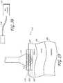
- Figure 2Cshows a cross-sectional view of the skin (as in Figure 2A ) illustrating that in certain embodiments it may be desirable to concentrate the treatment within a particular region of dermal 101 and hypodermis 100 tissue in which the target histological structures reside (e.g., "target tissue” 105) while doing minimal damage to the tissue above the target tissue 105 in the epidermis 102 and dermis 101 (e.g., "superficial non-target tissue” 103) and tissue structures within the hypodermis 100 (e.g., "deep non-target tissue” 104), as shown above to target the eccrine glands 107.
- tissue in which the target histological structures residee.g., "target tissue” 105
- tissue structures within the hypodermis 100e.g., "deep non-target tissue” 104
- the target tissue 105 regionmay begin anywhere from about 0.5 mm to about 4 mm beneath the skin's surface and end anywhere from about 1 mm to about 10 mm beneath the skin's surface in some embodiments.
- the superficial non-target tissue 103 regionmay begin at the skin surface and end anywhere from about 0.5 mm to about 4 mm beneath the skin's surface in some embodiments.
- the deep non-target tissue 104 regionmay begin anywhere from about 1 mm to about 10 mm beneath the skin's surface in some embodiments.
- microwave energycan be delivered to the eccrine 106 or apocrine 107 sweat glands to reduce sweating in a patient. Additionally, apocrine glands 107 can be treated to achieve a reduction in body odor.
- microwave therapycan be used to shrink collagen in the skin for the purposes of skin tightening, wrinkle reduction and/or body sculpting.
- microwave therapycan be used to treat hair follicles, acne, cellulite, vasculature such as varicose veins and telangiectasias, and various other structures disclosed in the application. Accordingly, the location of the target tissue 105 and non-target tissues 103, 104 may require adjustment based on the specific therapy desired.
- anatomical structures and clinical indicationsthat can be treated by the systems and methods disclosed herein are listed.
- a plurality of structures/disorderscan be treated in the same treatment session.
- Hyperhidrosisis a clinically diagnosed disorder in which there is excessive secretion of sweat from the sweat glands.
- the excessive sweatingwhich is thought to result from the over activity of the sympathetic nervous system, usually occurs in the palms, soles, and axillae.
- Palmar hyperhidrosisis a condition of excessive sweating in the hand. This condition is often exhibited in cold, wet handshakes.
- Plantar hyperhidrosisis a condition of excessive sweating in the foot. This condition may cause blisters and fungal infections.
- Axillary hyperhidrosisis a condition of excessive sweating in the armpit. Such excessive sweating is not only socially embarrassing but may even cause staining and rotting of clothes.
- the sweat glands in the bodyare comprised of the apocrine 107 and eccrine 106 glands.
- Eccrine sweat glands 106which lie superficially in the dermis layer 101 of the skin, are located all over the body so that they can secrete sweat to regulate body heat and temperature.
- Apocrine glands 107which exist within the hypodermis 100 and border on the interface between the hypodermis 100 and dermal layer 101, secrete an oily, milky, protein-rich product into the follicles. Bacterial digestion of apocrine sweat is largely responsible for osmidrosis or bromohidrosis (i.e., body odor), which can be most pronounced in the foot and underarm area.
- Antiperspirantsare aluminum based salts that mechanically block the sweat gland ducts, thereby preventing sweat from reaching the skin surface.
- Deodorantschange the pH of the skin surface, thereby minimizing the presence of smell inducing bacteria. Because the effects of both of these products are temporary and can irritate the skin in some users, these products are suboptimal solutions to cases of excessive sweating.
- Anticholinergic drugshave also been applied both topically and systemically to treat hyperhidrosis. These agents block the sympathetic stimulation of the eccrine glands 148 by inhibiting the action of acetylcholine at the nerve synapse. Use of these drugs is limited because of the systemic side effects they cause, including dry mouth, urinary retention, constipation, and visual disturbances such as mydriasis and cycloplegia. Moreover, topical anticholinergics sometimes have difficulty absorbing into the skin in sufficient quantities to affect the cholinergic nerve endings.
- botulinum type-A neurotoxine.g., BOTOXTM
- BOTOXis commonly used by dermatologists to denervate the neuroglandular junctions between the autonomic nerves and the sweat glands. With the nerve connections disabled, acetylcholine is prevented from reaching the eccrine sweat glands 106, thereby disabling a component of the hyperhidrosis patient's overactive sympathetic nervous system.
- This treatmentis not without its downsides.
- Botulinum toxinis one of the most lethal substances on earth and, consequently, injecting it in a patient's body is full of risk.
- botulinum toxinsince the apocrine sweat glands 107 are innervated by adrenergic nerves, which are not blocked by botulinum toxin, injections of botulinum toxin do not have a clinical impact on the body odor caused by the secretions from apocrine glands. Botulinum toxin treatment also requires multiple, painful injections with a needle. Furthermore, the results of this treatment last only a few months, thereby necessitating repeated costly and painful treatments.
- Wrinklesare also a very common skin condition precipitated by factors including the aging process, UV light exposure, and smoking.
- the epidermal cellsbecome thinner and less adherent to each other.
- the thinner cellsmake the skin look noticeably thinner.
- the decreased adherency of the cellsdecreases the effectiveness of the barrier function allowing moisture to be released instead of being kept in the skin, causing dryness.
- the number of epidermal cellsdecreases by approximately 10% per decade in some patients and divide more slowly as we age making the skin less able to repair itself quickly.
- the effects of aging on the dermal layer 101are significant. Not only does the dermal layer 101 thin, but also less collagen is produced, and the elastin fibers that provide elasticity wear out. These changes in the scaffolding of the skin cause the skin to wrinkle and sag. Also, over time, sebaceous glands 108 get bigger but produce less sebum, and the number of sweat glands decreases. Both of these changes lead to skin dryness.
- the rete-ridges of the dermal-epidermal junctionflatten out in the aging process, making the skin more fragile and easier to shear. This process also decreases the amount of nutrients available to the epidermis 102 by decreasing the surface area in contact with the dermis 101, also interfering with the skin's normal repair process.
- fat cellsget smaller with age. This leads to more noticeable wrinkles and sagging, as fat cells cannot "fill in” the damage from the other layers.
- Ablation of the epidermis 102can destroy older, damaged epidermal cells, bringing to the surface newer epidermal cells and stimulating collagen formation. Additionally, thermal contracture of deeper collagen fibers can induce overall skin contracture. For instance, contracture of deep dermal collagen and subcutaneous fibrous septae has been suggested as a potential mechanism of action for another thermal wrinkle treatment system marketed by Thermage, Inc. (Hayward, CA).
- Bromohidrosiscan occur, especially in the axilla and feet.
- Bromohidrosiswhich is often associated with hyperhidrosis, may occur due to one or more of the following: apocrine gland 107 dysfunction, bacterial and fungal infections, fatty acid decomposition producing a distinctive odor, ingestion of certain foods, and arsenic ingestion.
- Chromohidrosisis abnormally colored sweat due to dysfunction of the apocrine glands 107. Common sites include the face, where the color of sweat may be black, green, blue or yellow in some cases.
- Acneis a disorder of the pilosebaceous unit, which is made up of a hair follicle, sebaceous gland, and a hair. These units are found everywhere on the body except on the palms, soles, top of the feet, and the lower lip. The number of pilosebaceous units is greatest on the face, upper neck, and chest. Sebaceous glands 108 produce a substance called sebum, which is responsible for keeping the skin and hair moisturized. During adolescence, sebaceous glands 108 enlarge and produce more sebum under the influence of hormones called androgens. After about age 20, sebum production begins to decrease.
- a bacteriaknown as Propionibacterium acnes, is a normal inhabitant of the skin. It uses sebum as a nutrient for growth, and therefore increases in follicles during puberty.
- Sebum produced by the sebaceous gland 108combines with cells being sloughed off within the hair follicle and "fills up" the hair follicle. When the follicle is “full”, the sebum spreads over the skin surface giving the skin an oily appearance. When this process works correctly, the skin is moisturized and remains healthy.
- comedogenesisThe process of obstructing follicles is called comedogenesis. It causes some follicles to form a type of acne called comedones, also known as blackheads and whiteheads.
- Various medicationshave been used for the treatment of acne, including oral and topical retinoids, antibiotics, exfoliants, and surgical dermabrasion, which results in ablation of the stratum corneum layer of the epidermis. More recently, focal thermal therapy has been introduced. Heating individual sites of obstructed follicles and sebaceous glands 108 kills the bacteria within the gland, resulting in reduced inflammation.
- Celluliteis the dimpling of the skin, especially in the thigh and buttock regions. Cellulite generally affects women much more frequently than men. Although many therapies that presume cellulite is caused by an abnormality of adipose tissue have gained recent popularity, the basic pathophysiology of cellulite has not been clearly identified. Histopathologic samples have shown cellulite may be the result of irregular extrusion of adipose tissue from the hypodermis 100 into the dermis 101. Traditional therapies such as diet and exercise, and more invasive therapies such as panniculectomy or liposuction each have several disadvantages. A non-invasive way to target dermal adipose tissue without significantly affecting other structures is thus very desirable.
- Unwanted hair growthmay be caused by a number of factors including a genetic predisposition in the individual, endrocrinologic diseases such as hypertrichosis and androgen-influenced hirsuitism, as well as certain types of malignancies.
- endrocrinologic diseasessuch as hypertrichosis and androgen-influenced hirsuitism
- certain types of malignanciesIndividuals suffering from facial hirsuitism can be burdened to an extent that interferes with both social and professional activities and causes a great amount of distress. Consequently, methods and devices for treating unwanted hair and other subcutaneous histological features in a manner that effects a permanent pathological change are very desirable.
- melanin in the skinmay absorb so much light that skin ablation occurs simultaneously with hair follicle ablation.
- spider veinsare subcutaneous features. They exist as small capillary flow paths, largely lateral to the skin surface, which have been somewhat engorged by excessive pressure, producing the characteristic venous patterns visible at the skin surface. Apart from the unsightly cosmetic aspect, telangiecstasia can further have more serious medical implications. Therefore, methods and devices for treating spider veins and other subcutaneous histological features in a manner that effects a permanent pathological change to the appropriate tissues are highly desirable.
- spider veinsThe classical treatment for spider veins is sclerotherapy, wherein an injection needle is used to infuse at least a part of the vessel with a sclerotic solution that causes blood coagulation and blockage of the blood path. With time, the spider veins disappear as the blood flow finds other capillary paths. Since there can be a multitude of spider veins to be treated over a substantial area, this procedure is time-consuming, tedious, and often painful. It is also of uncertain effectiveness in any given application and requires a substantial delay before results can be observed.
- Another procedure for the treatment of shallow visible veinsinvolves the application of intense light energy for a brief interval.
- This techniqueexposes the skin surface and underlying tissue to concentrated wave energy, heating the vein structure to a level at which thermocoagulation occurs.
- these energy levelsare so high that they cause discomfort to some patients, and can also be dangerous to those in the vicinity, unless special precautions are taken.
- some patientscan be singed or burned, even though the exposure lasts only a fraction of a second.
- malignant and pre-malignant skin lesionsincluding actinic keratosis, basal cell carcinoma, squamous cell carcinoma, and melanoma, and benign skin lesions such as cysts, warts, nevi, café au lait spots, and vascular lesions would also benefit from a non-invasive localized treatment.
- skin and nail infections from bacteria, viruses, fungi, or parasitescould also benefit from a non-invasive local treatment method.
- the hypodermis layer 100is innervated by sensory nerve endings.
- a non-invasive local treatment for hyperesthesiae.g., from neurologic disorders such as, for example, multiple sclerosis and herpes zoster, would also be desirable.
- protective treatmentscan be employed to prevent damage or pain to non-target tissue.
- Surface coolingis applied to protect the epidermal layer 102 and portions of the dermal layer 101 of the skin while deeper regions of skin tissue are heated via energy delivery.
- Various types of active coolingcan be configured to provide this thermal protection to non-target tissue 103, 104.
- the delivery of therapymay also be facilitated by administering many of the treatments disclosed herein in one or more spatial configurations or skin geometries.
- treatmentcan be directed perpendicular to the skin surface, parallel to the skin plane or at some angle in between.
- the skincan be oriented in various configurations to achieve the desired energy delivery.
- energycan be delivered to the skin in a flat, planar configuration, in an elevated orientation or in a folded geometry.
- suctionis applied to the skin to achieve a particular orientation or geometry.
- Microwave therapymay also be facilitated by administering treatment over multiple stages and in a patterned arrangement. This approach can enhance the body's healing response, making for a quicker recovery with fewer complications.
- Various templatesare disclosed to assist in administering a staged and patterned treatment.
- Microwave therapymay also be facilitated by the introduction into the treatment zone or directly into the target tissues of exogenous microwave absorbers. Some substances, such as graphite, carbon black, or ferrite will preferentially absorb microwaves and increase the local thermal effect.
- the embodiments disclosed hereinrelate to the treatment of dermal and sub-dermal tissue structures via the transcutaneous delivery of energy.
- the system illustrated in Figures 3A - Bshows a device 110 having an energy applicator 111 for non-invasively delivering microwave energy 112 to the target tissue layer 105 and a microwave generator 113 for supplying the applicator 111 with microwave energy 112 via conduit 114 as shown in Figure 3B .
- the energy applicator 111comprises at least one antenna for delivering microwave energy 112 to the target tissue 105.
- the antennaswould be configured, when the device is placed against or near the patient's skin, to heat and treat the target tissue 105 and target structures within the target tissue 105.
- the treated target tissue 105could either be left in place to be resorbed by the body's immune system and wound healing response or be extracted using any number of minimally invasive techniques.
- cooling plate 115for preventing damage to superficial non-target tissue 103.
- Microwave energy 112is absorbed by the target tissue 105 by a process called dielectric heating.
- Molecules in the tissuesuch as water molecules, are electric dipoles, wherein they have a positive charge at one end and a negative charge at the other.
- the microwave energy 112induces an alternating electric field, the dipoles rotate in an attempt to align themselves with the field. This molecular rotation generates heat as the molecules hit one another and cause additional motion.
- the heatingis particularly efficient with liquid water molecules, which have a relatively high dipole moment.
- microwave heatingis particularly efficient when water molecules are present in tissue, it may be desirable to have a relatively high water content or molecule density at the target tissue or within the target structures. This high water content would result in greater microwave energy absorption and consequent heating at the point of treatment. Moreover, this phenomenon will allow the preferential heating of target tissue 105, thereby minimizing the impact to non-target tissue 103, 104.
- FIG. 4shows one embodiment of the injection of fluid 116 proximate to the base of a sweat gland and target tissue 105.
- the patientcan be induced to sweat in the area of treatment (such as by raising the ambient temperature or the temperature in the target area) in order to achieve higher water content in the target structures.
- the water dense sweat glandscan be plugged to prevent any of the water/sweat from escaping through the sweat ducts.
- Sealing the gland ductscan be achieved by using aluminum ion based topical products such as antiperspirants or any type of biocompatible polymer coating.
- the addition of external wateris not required in some embodiments.
- sweat glandsnaturally have a relatively high water content compared to surrounding tissue which can allow the sweat glands to preferentially absorb microwave energy 112.
- sweat glandsgenerally have a higher concentration of ions (e.g., a greater ionic potential) relative to surrounding tissue which also advantageously can allow for the preferential absorption of microwave energy with respect to the surrounding tissue.
- tissue of relatively low water contente.g., cellulite
- microwave energyaligning the e-field of the radiated signal to preferentially heat the low water content fat layer.
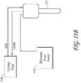
- an apparatus for treating target tissue 105 with microwave energycan be configured to include a processor (not shown), an energy generator 113 connected to the processor, and a device 117 operatively coupled to the generator.
- the device 117can further include an energy delivery applicator 111 or energy delivery element such as an antenna for delivering energy to the target tissue.
- a cable 114e.g., feedline
- the processor, the device, and/or the energy generator 113can be connected wirelessly via, for example, radio frequency signals.
- the energy generator 113is remotely located from the energy applicator 111, wherein the generator 113 can be either stationary or mobile.
- the applicator 111 and generator 113can be coupled such that they comprise a portable unit. Still alternatively, the applicator 111 and generator 113 can be combined into a single unit.
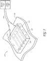
- FIG. 5is an isometric view depicting a non-invasive energy delivery device 117 comprising multiple microwave antennas 120 that are electrically connected to a microwave generator 113.
- the antennas 120are contained in a substantially planar applicator plate 121 sized for application against a target area of a patient's skin 119.
- the device 117 and the applicator plate 121 therein,can be sized and configured to substantially match the area of tissue being treated. Additionally, the applicator plate 121 may be flexible to help the device 117 conform to the contours of the patient's skin.
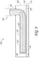
- FIG 6is a cross-sectional side view of the device 117 of Figure 5 showing the delivery of energy 112 into the skin.
- four or five microwave antennas 120are positioned parallel to each other. Fewer or greater microwave antennas 120 may be provided, for example, one, two, three, or at least four, five, six, seven, eight, nine, ten or more.
- the antenna(s) 120may be similar to that described in U.S. Patent Nos. 4,825,880 to Stauffer et al. or 6,330,479 to Stauffer .
- thermal protective measurescan be employed in conjunction with thermal treatments.
- the applicator plate 121 containing the antennas 120may be connected by a conduit 114 to the microwave generator 113, with cooling fluid passing through the conduit to and from the applicator plate 121 from a coolant circulator 118.
- the cooling fluidcreates a protected zone 103 in the epidermis 102 of the patient, so that target tissue 105 below the protected zone is treated.
- Protected zone 104 deep to target tissue 105is also illustrated.
- the amount of energy 112 delivered to the target tissue 105 and consequent extent of treatment effectcan be adjusted based on the number of antennas 120, their specific configuration and the power delivered to each antenna 120.
- a microwave energy output frequency ranging from 300 MHz to 20 GHzwould be suitable for feeding the energy delivery device with power.
- a microwave signal of anywhere from about 915 MHz to about 2450 MHzwould be preferential for yielding a treatment effect on tissue.
- a signal having a frequency ranging from about 2.5 GHz to about 10 GHzmay also be preferential.
- solid state, traveling wave tube and/or magnetron componentscan optionally be used to facilitate the delivery of microwave energy.
- the delivery of energy 112 to the target tissue 105can be facilitated by antenna 120 designs that incorporate a low-loss dielectric element that can take the form of a stand-off between the antenna 120 and tissue, and/or also a fill-material (e.g. a dielectric filled waveguide).
- a low-loss dielectric elementthat can take the form of a stand-off between the antenna 120 and tissue, and/or also a fill-material (e.g. a dielectric filled waveguide).
- microwave energycan be delivered through a low-loss dielectric material.
- a properly configured dielectric elementwill not impede the microwave energy from radiating to adjacent tissue and can be utilized as a design tool to help optimize the delivery of energy to the target tissue over the course of the treatment.
- a dielectric element that removes the antenna from direct contact with the skincan help maintain consistent energy delivery to the target tissue by ensuring a consistent load. This is achieved since the dielectric properties of the load in closest proximity to the antenna (i.e. the dielectric element) remain relatively consistent during a treatment compared to that of the skin and underlying tissue.
- a low-loss dielectrice.g., ceramic, PTFE, polyimid, etc. placed between the tissue and antenna can be utilized to maximize power transfer into the tissue.
- the dielectriccould be incorporated into the antenna itself (e.g. as a fill material), as an external component of the energy delivery device or system (e.g. as a dielectric "block" between the antenna and tissue), or as a combination of both. Further details regarding antenna designs are discussed below.
- the antennais built using a section of semi-rigid coaxial cable - with the antenna at one end and a microwave generator at the other end. The antenna is then connected to the generator with a long section of flexible microwave cable.
- the waveguide antennacan include a section of waveguide tubing with an appropriate shape or geometry depending on the desired clinical result.
- the coaxial cablefurther comprises an inner conductor shaft and outer conductor.
- an inner conductor element 123extends from the inner conductor shaft 124 and beyond the outer conductor 125. Electromagnetic energy is radiated from the antenna 122 with an omnidirectional radiation pattern 126 around the circumference of the wire 125.
- a conductive shield or sleeve 127is added to the antenna 122 to choke off unwanted current flow down the outer conductor 125 of the coaxial line, thus limiting proximally radiating electromagnetic fields.
- dipole antenna 128 configurationsas illustrated in Figure 7B , the outer conductor 125 is exposed in such a manner that electric field lines stretch from the inner conductor element 123 to the outer conductor 125.
- the antennamay optionally comprise a helical antenna 129 shown in Figure 7C , a loop antenna 130 shown in Figure 7D , or a horn antenna 131 shown in Figures 7F-G .
- These alternative antenna configurationsprovide geometric radiating patterns.
- the outer conductor 125may comprise a shaped element, such as a horn shape, to provide a directional component to the field created between the inner conductor element 123 and outer conductor 125.
- the outer conductor element 125 and/or inner conductor element 123may be bordered by, coupled to or coated by a dielectric element to optimize the energy delivery capabilities of the antenna.
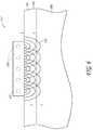
- the applicator 312comprises an antenna 132 connected to a coaxial cable 133 that is coupled to a microwave power source (not shown). As illustrated in Figure 8A , the antenna 132 further comprises an inner conductor 123 disposed within the coaxial cable 133, wherein an inner conductor element 123 extends beyond the distal end of the coaxial cable 133 to form a coiled conductor element. Also shown are cooling inlets 134 and outlets 135 demarcated by arrows.
- the coiled conductor elementprovides a relatively flat structure which can be aligned with the skin surface to deliver an even amount of energy to a plane of target tissue.
- the applicatormay optionally further comprise at its distal end a thin shield comprised of a polymer or ceramic.
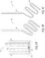
- Figures 8B and 8Crespectively illustrate additional embodiments 136, 137 of the coiled antenna configuration, wherein the coiled conductor element may comprise the entire coaxial cable 133 ( Fig. 8B ) or just the inner conductor 123 ( Figure 8C ).
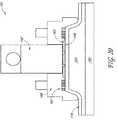
- FIG. 9depicts a cross-sectional view of slot antenna 138 comprised of coaxial cable 133 and shielding 139.
- the coaxial cable 133which is connected to a microwave generator (not shown), is comprised of an inner conductor 123 and outer conductor 125, wherein the inner conductor 123 and outer conductor 125 are coupled together with solder 140 at the distal portion 141 of the antenna 138.
- the outer conductor 125comprises a circumferential slot 142 through which the electromagnetic field of the antenna 138 radiates in an omnidirectional pattern.
- the shielding component 139is used to direct the electromagnetic field toward the treatment area, thereby minimizing loss and maximizing efficiency, and to prevent stray radiation of electromagnetic fields. Since coaxial slot antennas 138 are fed in an unbalanced configuration, and are subject to proximal current flow down the outer conductor, a proximally radiated electromagnetic field can propagate longitudinally down the coaxial antenna, and may result in an undesirable treatment effect to the superficial non-target tissue 103, 104 that sits adjacent to the antenna. To avoid this outcome, the proximal portion 143 of the antenna 138 can be bent away from the treatment area such as at 144 such that the surface currents and accompanying fields are directed away from the non-target tissue 103, 104.
- the slot antenna systemmay also include a cooling circuit 118 and cooling plate 115 as shown.
- microwave antennascan also be used with the present application, for example, waveguide, single or multiple slot antennas, printed slot antennas, patch antennas, and Vivaldi antennas.
- the microwave generator 113preferably includes a generator head, a power supply, and an isolator.
- the generator 113may be configured to have a frequency of 5.8GHz, and have an output power maximum, in some embodiments, of no more than about 300W, 200W, 100W, 75W, or less.
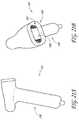
- the systemincludes a waveguide antenna 145 (as shown, for example, in Fig. 20 ).
- the antennahas a resonant frequency of 5.8GHz.
- the waveguide antenna 145preferably has a cross-sectional size configured to the desired operational frequency and field configuration of the waveguide 145.
- the lowest-order Transverse Electric (TE) modesare utilized (e.g., TE 10 ), although others are possible, such as Transverse Magnetic (TM), Transverse ElectroMagnetic (TEM), evanescent, or a hybrid mode.
- TMTransverse Magnetic
- TEMTransverse ElectroMagnetic
- evanescente.g., TE 10
- the width and height (rectangular) or diameter (circular) waveguide geometrycorrelate with the operational frequency and field configuration of the waveguide 145.
- Additional parameters, such as the fill material, the type and placement of feed, and the use of mode filteringaffect the operational frequency and field configuration of a waveguide 145.
- a transverse mode of a beam of electromagnetic radiationis a particular intensity pattern of radiation measured in a plane perpendicular (i.e. transverse) to the propagation direction of the beam. Transverse modes occur in microwaves confined to a waveguide 145.
- Transverse modesoccur because of boundary conditions imposed on the wave by the waveguide 145.
- the allowed modescan be found by solving Maxwell's equations for the boundary conditions of a given waveguide 145.
- Transverse modesare classified into different types. TE modes (Transverse Electric) have no electric field in the direction of propagation.
- TM modesTransverse Magnetic
- TEM modesTransverse ElectroMagnetic
- Hybrid modesare those which have both electric and magnetic field components in the direction of propagation.
- An evanescent fieldis a time-varying field having an amplitude that decreases monotonically as a function of transverse radial distance from the waveguide 145, but without an accompanying phase shift. The evanescent field is coupled, i.e., bound, to an electromagnetic wave or mode propagating inside the waveguide 145.
- the length of the waveguide 145can be adjusted such that the physical length of the waveguide 145 corresponds to an electrical length that is a half-wavelength multiple of the guided wavelength 145 at the desired operational frequency. This allows an efficient match from the waveguide 145 feed into the load.
- the waveguide 145can have a wide variety of cross-sectional geometries depending on the desired clinical objective and geometry of the particular anatomical area to be treated. In some embodiments, the waveguide 145 has a rectangular, circular, elliptical, or hexagonal cross-sectional geometry.
- the coaxial feedcan be placed between about 0mm to a distance equal to the guided wavelength ( ⁇ g ) with an insertion depth of 1mm to 100mm. The placement is most preferably optimized for efficient transfer of power from coaxial feed to waveguide.
- the coaxial feedhas an insertion depth of between about 5% to 95% of the depth of the waveguide 145. In some embodiments, the coaxial feed has an insertion depth of at least about 80% of the depth of the waveguide 145.
- the antenna 120can be within 0.5-5 mm of the skin (e.g., between about 1.5-2mm, such as about 1.75 mm) in some embodiments, or within several wavelengths of the skin at a given operational frequency in other embodiments. This distance may be referred to herein as the antenna standoff height. Variation of the standoff height affects the spread of the microwave radiation. With a very large standoff, a reduced energy density over a larger volume is achieved. Conversely, with little to no standoff height the energy density is generally much higher over a smaller volume. To achieve therapeutic energy density levels with a large standoff, significantly increased input power levels are necessary.
- standoff heightcauses large variation in the loading conditions for the waveguide, with reflected power levels observed by the waveguide antenna 145 changing with standoff changes.
- the standoff heightcould be about zero or even negative (e.g., the skin could be within the waveguide 145).
- dielectric filler materialshave a permittivity that is closer to that of tissue, giving the potential for lower reflection in general between the applicator/tissue interface.
- the dielectric filler materialmay be selected based on having a dielectric constant that matches well to the cooling element 115 and skin.
- a microwave antenna systeme.g., a waveguide system
- a metal, adjustable tuning stubthat can be utilized for optimal power transfer into a given tissue to further minimize reflections for a given tissue load at a specific frequency.
- This enhancementcan help account for variations in manufacturing and tolerance. Instead of having high tolerance requirements, which might be cost prohibitive, each antenna can be tuned to achieve desired functional characteristics.
- the metal tuning stubcan be secured to a wall of the antenna (e.g., the waveguide 145) by a suitable means such as adhesion, a rivet, soldering, or the like.
- the stubcan be a cylindrical member depending from the top wall transversely to the waveguide 145 path and located substantially on the longitudinal centerline of the waveguide.
- the stubcan extend to various depths in the waveguide 145 and is sized and located accurately so as to optimally match the impedance that the waveguide antenna 145 presents to the generator 113, allowing efficient power transfer.
- the tuning stubadvantageously provides a reactive impedance substantially without a resistance component.
- Waveguide applicatorscan be placed in an array configuration for simultaneous or sequential treatment of multiple sites. Additionally, the possibility exists for beneficial phased (constructive effect of in-phase fields) operation of a waveguide array (similar to the twin coaxial slot antennas), as discussed elsewhere in the application.
- the aperture of the waveguide antennacan be flared outward in a distal direction to form a horn antenna configuration. This can spread the energy dispersion more widely, as well as increase the robustness of the antenna to varying tissue loads (i.e. the antenna will match well with patient to patient variation in tissue composition).
- the wider footprint created by a flared antennaprovides the potential for an increased treatment size.
- the flarecan also advantageously increase the manufacturing tolerance for the waveguide. For example, a horn antenna with a desired frequency of 5.8GHz may have a frequency range of about 5.5 to 6GHz in some embodiments.
- an energy delivery devicecan include a cooling element 115 for providing a cooling effect to the superficial non-target tissue 103 (e.g., the epidermis 102 and portions of the dermis 101).
- the cooling element 115will establish a zone of thermal protection 103 for the superficial non-target tissue as illustrated in Figure 10A .
- the target tissue 105e.g., zone of thermal treatment 105 in Figure 10A
- the target tissue 105can be treated with minimal risk of thermal damage to non-target tissues 103, 104.
- Figure 10B aboveillustrates a time-temperature curve illustrating the skin temperature above which a burn would be expected (curve B) and below which no appreciable injury would occur (curve A). Therefore, it would be very desirable that during energy treatment the cooling system maintain the non-target skin surface temperature (which can be measured by the temperature sensing element as discussed elsewhere in the application) below curve B for a given treatment duration, as well as below curve A in some embodiments.
- the cooling element 115can further cool the superficial non-target tissue 103 to create a numbing effect.
- the cooling treatment and resulting cooling and/or numbing effectmay be applied before, during and/or after the thermal treatment.
- Protective coolingmay also be applied in an alternating fashion with the heating treatment to maximize energy delivery while minimizing adverse effects to non-target tissue 103, 104.
- the cooling element 115 of the inventionhas active cooling.
- the cooling element not according to the inventioncan be a passive heat sink that conductively cools the skin, such as a layer of static, chilled liquid (e.g., water, saline) or a solid coolant (e.g., ice, ceramic plate), a phase change liquid selected which turns into a gas, or some combination thereof (e.g., a cylinder filled with chilled water).
- the cooling element 115can also provide active cooling in the form of a spray or stream of gas or liquid, or aerosol particles for convective cooling of the epidermis 102.
- a thermo-electric cooler (TEC) or Peltier elementcan also be an effective active cooling element 115.
- an active cooling element 115can comprise a thermally conductive element with an adjacent circulating fluid to carry away heat.
- the cooling element 115can also be incorporated into the device as an internal cooling component for conductively cooling non-target tissue 103, 104.
- an energy delivery devicecan couple a cooling component 115 to the energy applicator, where the cooling component 115 can actively or passively provide conductive cooling to adjacent tissue.
- the cooling component 115may comprise a cold metal plate or block.
- the cooling component 115may comprise a thermally conductive element, wherein a chilled liquid (e.g., water, dry ice, alcohol, anti-freeze) is circulated through the element's internal structure.
- a chilled liquide.g., water, dry ice, alcohol, anti-freeze
- the dielectricitself can be a cooling component.
- the cooling component 115can be incorporated into the antenna 120 such that it is adjacent to the dielectric.
- a cooling component 115can be incorporated into an energy delivery device 146 comprising at least one microwave antenna 120, such as described above.
- fluidis used to cool adjacent skin tissue 119.
- This convective coolingcan be enhanced by a coolant circulator 118 that could optionally be integrated within, coupled to or located remotely from the energy generator 113.
- the cooling circulator 118is located remote from both the energy source 113 and energy applicator 121.
- the properties and characteristics (e.g., medium, flow rate, temperature) of the circulating fluid (gas or liquid)can be selected and modified to achieve the desired cooling effect in light of the amount and rate of energy delivered to the target tissue.
- Coolant with high ionic contentgenerally has a high conductivity, leading to microwave absorption and heating, disrupting the microwave field and altering the energy delivery to the tissue.
- Some examples of low-loss coolantinclude deionized water and/or one or more of the following: vegetable oil, such as peanut, canola, sunflower, safflower, or olive oil, distilled water and alcohol, or isopropyl alcohol.
- the coolant usedis isopropyl alcohol, which advantageously allows for liquid cooling at lower temperatures because the freezing point of isopropyl alcohol is lower than that of water. While liquid coolants have been described, gas and solid coolants are also within the scope of the invention.
- a cooling platein some embodiments, preferably includes one or more of the following functions: (1) it is thermally conductive, that is, it controls heat transfer rate between tissue and cooling fluid; (2) it is thin (e.g., less than about 1mm, 0.75mm, 0.5mm, 0.25mm, 0.20mm or less in some embodiments) relative to the wavelength of the microwave signal and has low electrical conductivity (e.g., sigma of less than about 0.5, such as less than about 0.01 in some embodiments) in order to maximize the efficiency of power transfer into the tissue/thermal conductivity, to keep the waveguide 145 close to the skin and minimize standoff height; (3) it is of adequate stiffness to eliminate bowing while conforming to the skin, thereby maintaining consistent cooling (via constant contact with skin and uniform flow geometries (4) it is made of materials that are transparent to microwave energy (e.g., non-reflective).
- a cooling platemay be made of any suitable material, for example, glass or a ceramic composite including about 96% alumina, or a pyrolytic
- the cooling plateis preferably sufficiently thin to minimize undesirable microwave reflection.
- the cooling platemay be no more than about 10mm, 9mm, 8mm, 7mm, 6mm, 5mm, 4mm, 3mm, 2mm, 1mm, 0.75mm, 0.5mm, or less in thickness.
- the interface between waveguide 145 (outer wall) and fillingin some embodiments, has minimal air gaps, such as less than about 3mm, 2mm, 1.5mm, 1mm, 0.5mm, or less to help avoid unwanted e-fields. Interface between the waveguide cooling element 115 and less housing or cooling chamber should have no air gaps.
- the flow chamber of a cooling systemincludes inlet and outlet reservoirs to achieve a consistent flow rate across the flow chamber. Reservoirs are located on either side of the flow chamber.
- the inlet reservoirallows for the accumulation of coolant such that the fluid can flow through the cooling chamber at nearly the same rate at any point in the cooling chamber. This constant flow rate allows for consistent cooling across the cooling plate, to provide a thermally conductive barrier.
- the reservoir at the outlethelps to advantageously prevent fluid backup that would inhibit flow across the flow chamber.
- the cooling circuitalso preferably includes a temperature control element to cool or heat fluid to the desired temperature, and a pump.
- the pumpmay be a conventional pump within the circuit, or alternatively a pump that functions outside of the cooling circuit, such as a roller pump.
- the flow rate of the cooling fluidmay be adjusted for any desired cooling.
- the flow ratecan be between about 100 and 1,500 ml/min, such as between about 200-600 ml/min, between about 200-400 mL/min, or about 600mL/min in certain embodiments.
- the temperature of the cooling fluid across the cooling plateis preferably between about -5°C-40°C, such as between 10°C-37°C, or about 10°C or 22°C in certain embodiments.
- the geometry and surface area of the cooling plateis preferably proportional with respect to the surface area and geometry of the body surface to be treated.
- treatmentis administered topically and/or in a minimally-invasive fashion to achieve the desired treatment effect on target tissue.
- the skinis depicted as a flat, multilayer plane of tissue, wherein treatment can be administered to target tissue in a manner that is substantially perpendicular to its planar surface.
- a treatmentmay be disclosed with respect to a particular skin geometry (e.g., perpendicular topical delivery, perpendicular percutaneous insertion, etc.), such treatment may be administered with respect to any number or variety of geometries, including those discussed below.
- a vacuum 147is used to pull and hold the skin 119, thereby elevating it for treatment.
- a vacuum-suction device 147is incorporated into an energy delivery device such that suction and energy delivery can be applied in unison.
- a tool utilizing a sterile adhesivecan effectively prop up the skin for treatment. More simply, however, a clinician can use any number of clamps, tongs or other devices to achieve and maintain skin elevation for and during treatment.
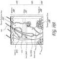
- FIG. 13shows an example of a skin fold 148.
- the skin fold 148comprises a top 149, two sides 150 (only one shown), two edges 151 (only one shown) and a zone of "sandwiched" target tissue 152 along the longitudinal length of the fold (e.g., treatment zone).
- Focusing treatment on the target tissue 152 rich region within the skin fold 133will allow for a more efficient procedure as two adjacent layers of target tissue can be treated in a single treatment. Additionally, treatment can be administered from one or more orientations (e.g., both sides of the fold), which can result in a more effective and reliable treatment. Also, since the skin is being pulled away from the body, damage to non-target structures 155 is minimized. Moreover, since the act of pinching or suctioning the skin fold 148 into position temporarily restricts blood flow to the folded tissue, there is less chance that the thermal energy delivered during treatment will be dissipated by blood flow. Additionally, the neural activity caused in the skin by the folded configuration may reduce the patient's pain sensation during treatment under the gate control theory of pain management (discussed below), which can be applicable for both vacuum lifting of the skin as well as manual "pinching" of the skin.
- the skin fold 148is treated from opposite sides by an energy delivery device comprising two energy delivery elements 154.
- the energy delivery elements 154are configured to deliver energy to the treatment zone 148 in the middle of the fold.
- the microwave energy 112can cross the outer epidermal layers 102 from each side of the skin fold and penetrate deep into the treatment zone 152.
- a dielectriccan optionally be used in this treatment.
- cooling elements 115can also be used on the skin surface to create a zone of protection 155 for non-target tissue. Additionally, the device 153 can be configured with a cooling element 115 and/or dielectric element on either side of the skin fold 148 to stabilize the fold during treatment.
- Treatmentcan be concentrated and localized at the target tissue 152 using the summation effect of two or more energy signals.
- antennassuch as the slot antennas 138 shown, can be positioned on either side (such as 139) of the skin fold 133 to deliver continuous microwave treatment from both sides of the skin fold.
- the energy waves from each antenna 138can be phased such that the wave from a first antenna 138 can harmonize with the wave from a second antenna 138 and yield a cumulative treatment effect at the zone of target tissue 152.
- the wavescan also be synchronized such that they cancel one another out in areas where treatment is not desired (i.e., non-target tissue).
- the optimal treatmentwould comprise antennas 138 configured and coordinated to deliver energy waves that are additive at the target tissue dense region but subtractive at other regions.
- FIGS 16A-Bshow perspective views of a suction system 147 comprising a housing 156, a suction chamber 157, a vacuum port (not shown) for connection to a vacuum source (not shown) and twin slot microwave antennas 138 operably connected to a power source via coaxial cables 133. Also shown are cooling flow inlet 134 and outlet 135 ports for each antenna 138.
- the vacuum sourcecan be configured for providing sufficient vacuum force to grasp and hold the skin in a folded orientation within the tissue chamber 157.
- the devicemay utilize the suction 147 for simply grasping the skin at the beginning of the procedure or holding the skin in place for some or all of the treatment. This area of lower pressure or suction within the device will help adhere the device to the skin so as to bring the target tissue into closer apposition to the antenna 138 and reduce blood flow in the target tissue, thereby enabling more efficient heating of the tissue.
- suctionhas a number of additional benefits.
- suctioncan be useful in orienting the skin in the desired geometry.
- suctioncan help grasp and retain the skin in either the folded skin or elevated configurations.
- treatment variabilitycan be minimized. Clinicians will not have to worry about maintaining consistent contact force since that will be regulated by the suction.
- suctioningmay allow for advantageous temporary occlusion of blood vessels superficial to or in the same plane as the target tissue, in embodiments where blood vessels are not preferentially targeted.
- the water content of the vesselswould thus be decreased and prevent undesirable coagulation via microwave energy.
- Thiscan also provide a heat-sink effect as microwave energy would be more efficiently directed to the target tissue rather than be directed to the non-target blood vessels.
- suctionsuch that blood remains in the vessel such that the vessel preferentially absorbs microwave energy, such as, for example, to treat telangiectasias or varicose veins.
- suctionmay help to control pain by triggering stretch and pressure receptors in the skin, thereby blocking pain signals via the gate control theory of pain management.
- the gate control theoryholds that an overabundance of nerve signals arriving at the dorsal root ganglion of the spinal cord will overwhelm the system, and mask or block the transmission of pain receptor signals to the brain. This mechanism of pain management is exploited by implantable electrical pain control units, TENS systems, the Optilase system and others.
- a suction system 147includes a vacuum pump configured with sufficient pressure for the area of tissue acquisition desired.
- the pressurecan be between about 450-700mm Hg, and about 650mm Hg in some embodiments.
- the geometry of the area covered by the chambercan be ovoid in some embodiments, or any other desired shape.
- the suction chamber 157may have a 15cm x 25cm central rectangular area with two lateral 7.5cm radius arc regions.
- the chamber depthis less than about 30mm, 25mm, 20mm, 15mm, 10mm, 7.5mm, 5mm, or less.
- the chamber wallsmay, in some embodiments, be angled out from the base of the chamber 157, e.g., between about 5-30 degrees, such as about 20 degrees.
- the depth of the suction chamber 157controls the amount that the skin is elevated when acquired and treated, which, in turn, impacts the lesion formed within the skin tissue.
- a subdermal lesionis created in the compressed tissue.
- the suction 147is released and the skin is disengaged from the chamber 157 and its compressed state, the lesion is stretched out. The result is a thinner and wider subdermal lesion.
- the suction system 147also can include one or more suction ports, e.g., two ports, each connected via a suction channel to a suction zone.
- the suction zonedefines a pattern to maximize suction area, which in turn maximizes suction force.
- the suction areaalso prevents tissue distortion.
- the portsmay be connected by a suction conduit that can split into distal branches to mate with each suction port.
- the system 147may also include a control element, such as a CPU, to control various parameters as noted above.
- the preferred treatment sequenceis (1) suction to acquire the desired tissue; (2) pre-cool the desired tissue; (3) deliver energy to the tissue; (4) post-cool the tissue; and (5) release the suction.
- Other tissue acquisition systems, devices, and methodsthat can be used with embodiments described herein are disclosed, for example, at pp. 69-71 of U.S. Provisional Application No. 61/045,937 , previously incorporated by reference in its entirety.
- Table 1is a non-limiting listing of various parameters that can be altered to control the thickness of the lesion created by the delivered energy, as well as the depth of the protection zone created by the cooling system. Ranges listed are for certain embodiments only; other ranges or values outside the listed ranges are also within the scope of the invention.
- Table 1Effect of Varying Certain Parameters Parameter Protection Zone Depth Lesion Size Range ⁇ Power Decrease Increase 20-100W, 40-70W ⁇ Frequency Decrease Decrease 5.8GHz ⁇ Coolant Temp (hotter) Decrease Increase -5C - 40C, 10-25C, 10C, 22C ⁇ Coolant flow rate Increase Decrease 100-1500 ml/min, 300-600ml/min, 600mL/min ⁇ Depth of suction chamber Decrease Decrease 1-20mm, 7.5mm ⁇ Duration of Energy delivery Decrease Increase 0.1 sec - 60 secs; 2-5 secs ⁇ Duration of pre-cooling Increase Decrease 0-60s, 0-5s ⁇ Duration of post-cooling Increase Decrease 0-60s, 0-20s
- the systemalso includes one or more temperature sensors.
- the sensorsmay be a thermocouple (TC), a thermistor, or a fiber optic sensor (which advantageously will not interact with microwave energy if lacking metal).
- the temperature sensoris a thermocouple sensor located at the interface between the skin surface and the cooling plate.
- Some embodimentsmay also optionally include a thermocouple sensor to measure the temperature of the coolant inflow and/or outflow reservoirs.
- the systemmay also include a feedback loop configured to adjust the energy delivered and/or coolant temperature, or alternatively shut off the system, for example, if a preset maximum skin or coolant temperature is identified.
- Other sensorssuch as pressure or distance sensors can be present to confirm skin contact and engagement.
- the target tissue 105is damaged to yield a treatment effect.
- non-target tissue 103, 104may also be affected in some of these treatments.
- Such treatmentsmay have complications such as pain, inflammation, infection, and scarring, which may occur both during and after treatment. Therefore, it may be beneficial to provide the patient with medications prior to, during and/or after the treatment to minimize the incidence and impact of these complications.
- the medicationswhich could be anesthetics for pain, such as lidocaine, ropivacaine, bupivacaine, tetracaine, and procaine; steroids or nonsteroidal agents for inflammation and antibiotics for infection, can be administered orally, topically, intravenously, or via local injection.
- controlled delivery of energymay be helpful in avoiding unnecessary damage to target tissue 105 (e.g., desiccation, charring, etc.) and non-target tissue 103, 104 as a result of overheating.
- a controlled delivery of energymay also result in a more consistent, predictable and efficient overall treatment. Accordingly, it may be beneficial to incorporate into the energy delivery system a controller having programmed instructions for delivering energy to tissue. Additionally, these programmed instructions may comprise an algorithm for automating the controlled delivery of energy.
- the aforementioned controllercan be incorporated into or coupled to a power generator, wherein the controller commands the power generator in accordance with a preset algorithm comprising temperature and/or power profiles.
- These profilesmay define parameters that can be used in order to achieve the desired treatment effect in the target tissue. These parameters may include, but are not limited to, power and time increments, maximum allowable temperature, and ramp rate (i.e., the rate of temperature/power increase).
- Feedback signalscomprising real-time or delayed physiological and diagnostic measurements can be used to modulate these parameters and the overall delivery of energy.
- temperature, impedance and/or reflected power at the treatment site and/or target tissue 105can be particularly useful.
- the energy controllermay have fixed coefficients or the controller coefficients may be varied depending upon the sensed tissue response to energy delivery.
- an algorithmcomprising a safety profile may be employed to limit energy delivery or to limit sensed tissue temperature. These algorithms could shut off energy delivery or modulate the energy delivery.
- the protective coolingcan be modulated based on the monitored data.
- the temperature of the target tissuecan be indirectly and noninvasively monitored by determining the temperature of a superficial non-target tissue 103, e.g., at the surface of the skin, and extrapolating from that temperature measurement the target tissue temperature. Adjustments can be made for the skin thickness of a particular patient. In some embodiments, it is desirable to maintain the superficial non-target tissue 103 temperature at less than about 45°C.
- Temperaturecan be measured using any number of sensors, including thermocouples and thermistors, wherein such sensors can be incorporated into the energy delivery element 154, the energy delivery device and/or the energy delivery system.
- a thermocouplecan be imbedded in the energy applicator, positioned adjacent to the antenna as part of the energy delivery device or located separate from the device such that the thermocouple is wired directly to the generator.
- the temperature measuredcan be that of the tissue immediately adjacent the device, the target tissue or any other tissue that may provide useful temperature measurements.
- a sensor that is incorporated into the energy delivery elementmay measure the temperature of the element itself.
- Impedancecan be measured by observing a tissue's response to electrical stimulation. This measurement is useful because it can help assess the extent of energy delivery to and through tissue. For example, energy that is directed to tissue having high impedance may have difficulty infiltrating deeper regions of tissue. This is particularly important in the case of skin tissue, as the impedance of skin can change over the course of treatment. As tissue is heated, it loses moisture and its conductivity drops and impedance increases. If the tissue is heated until it is desiccated, the resistivity of the tissue may impair energy delivery to surrounding tissue via electrical conduction. Employing impedance measurement feedback in the energy delivery system can optimize the delivery of energy to target tissue 105 while avoiding adverse consequences to both the target 105 and non-target tissue 103, 104.
- the treatmentcan be patterned such that sections of target tissue 105 are treated in the initial stage while other sections are treated in subsequent stages.
- a patientcould have the regions marked "A" treated in a first stage and the regions marked "B" treated in a second stage.
- the treatmentcould be broken down into further stages such as at least 3, 4, 5, 6, or more stages and additional regions.
- treatmentcould be administered to the same regions in multiple stages such that each region receives treatment multiple times.
- the treatment to a particular regionmay vary, such as with an increased or decreased amount of energy, or with a different treatment type.
- a staged treatmentgives the body the opportunity to heal between treatments. This is particularly important since treating or thermally damaging discrete regions of tissue over several sessions may have fewer and less severe complications compared to treating or thermally damaging a relatively large area of tissue in one session.
- a patterned treatment having small regions of treatmentmay elicit a more favorable healing response. Since healing time is related to the distance that fibroblasts must migrate from surrounding tissue, smaller treatment areas may heal much faster than larger treatment areas.
- Figures 18A-Eillustrate examples of various patterned treatments.
- a staged and patterned treatmentmay provide the opportunity to track the treatment's efficacy and provide follow-up treatments tailored to the patient's specific needs.
- the cliniciancan have follow-up sessions where sweating is mapped (e.g., iodine staining) to (1) identify the remaining areas for treatment and (2) determine the overall reduction in sweating in the underarm area.
- a staged treatmentmay allow them to discontinue treatment at a particular point.
- a patient suffering from a severe case of axillary hyperhidrosismay be satisfied with at least about 20%, 30%, 40%, 50%, 60%, 70%, 80%, 90% or more reduction in sweating and may only wish to participate in the number of treatments necessary for such reduction.
- a staged and patterned treatmentcan minimize the body's contracture response during the healing process.
- fibrosisor scarring
- fibroblastslay down a mesh of collagen to facilitate the healing of tissue.
- the treated areacontracts, thereby tightening the skin within that region.
- contracturecould potentially impair the patient's full range of arm motion.
- a treatmentcan be patterned and staged to minimize contracture and/or its impact on the patient. For example, the slender treatment areas depicted in Figure 18C would result in minimal axillary contracture and resulting impairment to range of arm motion.
- a templatecan be used to facilitate the application of a staged and/or patterned treatment.
- Figure 19illustrates a staged treatment series comprising three templates 158, 159, 160 wherein each template is configured to allow treatment to a different portion of the overall treatment area.
- the templates 158, 159, 160may be configured to engage an energy delivery device or one or more energy delivery elements (not shown) to facilitate the application of a staged and/or patterned treatment.
- the templates 158, 159, 160can be comprised of a single frame made from an appropriate material such as, for example, wood, plastic or metal with removable or adjustable pieces to reflect the desired pattern and/or stage.
- the templates 158, 159, 160may also be of one or more patterns that are drawn on the patient's skin using a temporary marker, tattoo or dye (e.g., henna) that will remain over the course of multiple staged treatments.
- a system and method for using microwave energy to thermally affect the sweat glands and surrounding tissue non-invasivelymay be useful in treating, for example, excessive sweating, or hyperhidrosis.
- the systemincludes a microwave generator, a microwave applicator, a cooling component, and a tissue acquisition component.
- the microwave applicatorincludes one or more microwave antennas that are placed against or adjacent the patient's skin and configured to deliver energy to a target layer at a designated depth of a patient's skin, specifically to the region of the dermis and hypodermis where sweat glands reside. Shielding is provided around the applicator in certain embodiments to localize the microwave energy to a targeted region of the patient's skin.
- the cooling componentincludes a ceramic cooling plate (such as made of ceramic) configured to contact the skin of a patient and protectively cool a layer of skin above the target layer, e.g., the epidermis.
- the cooling componentalso includes a coolant flow circuit chamber adjacent to the cooling plate configured to receive a cooling fluid.
- the cooling componentalso includes a temperature regulating component to cool or heat the fluid and a pump to circulate the fluid.
- the tissue acquisition componentincludes a suction chamber for elevating and receiving the skin to be treated, one or more suction ports in communication with a vacuum pump, and a thermocouple wire for measuring the temperature of the skin.
- a method of reducing sweat productioninvolves identifying an area of skin to be treated; activating the vacuum pump to acquire the skin within a suction chamber; cooling a first layer of the skin via a cooling element; delivering microwave energy to a second layer of skin containing sweat glands while the first layer of the skin is protectively cooled, the second layer deeper than the first layer relative to the skin surface; and deactivating the vacuum pump to release the skin.
- FIG 20illustrates schematically a microwave applicator system 161 for treating various skin features, according to the present invention.
- the systemincludes a waveguide antenna 145 operably connected to a coaxial cable (not shown), which is in turn connected to a microwave generator 113 (not shown).
- the microwave generator 113preferably includes a generator head, a power supply, and an isolator.
- the generator 113may be configured to have a frequency of 5.8GHz, and have an output power maximum, in some embodiments, of no more than about 300W, 200W, 100W, 75W, or less.
- the antenna 145has a frequency of 5.8GHz.
- the waveguide antenna 145preferably has a cross-sectional size configured to the desired operational frequency and field configuration of the waveguide.
- the lowest-order Transverse Electric (TE) modesare utilized (e.g., TE 10 ), although others are possible, such as Transverse Magnetic (TM), Transverse ElectroMagnetic (TEM), effervescent, or a hybrid mode.
- TMTransverse Magnetic
- TEMTransverse ElectroMagnetic
- effervescenteffervescent
- hybrid modee.g., TE 10
- the width and height (rectangular) or diameter (circular) waveguide geometrycorrelate with the operational frequency and field configuration of the waveguide 145.
- the length of the waveguide 145is preferably adjusted such that the physical length of the waveguide 145 corresponds to an electrical length that is a half-wavelength multiple of the guided wavelength at the desired operational frequency.
- the waveguide 145can have any cross-sectional geometry depending on the desired clinical objective and geometry of the particular anatomical area to be treated.
- the waveguide 145has a rectangular, circular, elliptical, or hexagonal cross-sectional geometry.
- the coaxial feed(not shown) can be placed between about 1mm to 10mm from the (inner) back wall of the waveguide 145, with an insertion depth of 1mm to 7mm.
- the placementis most preferably optimized for efficient transfer of power from coaxial feed to waveguide 145.
- the antenna 145be within 0.5-5 mm of the epidermis 102 (e.g., between about 1.5-2mm, such as about 1.75 mm). This distance may be referred to herein as the antenna standoff height 162, as shown in Figure 22A , which shows a slot antenna configuration. Variation of the standoff height 162 affects the spread of the microwave radiation. With a very large standoff height 162, a reduced energy density over a larger volume is achieved. Conversely, with little to no standoff height 162 the energy density is generally much higher over a smaller volume. To achieve therapeutic energy density levels with a large standoff height 162, significantly increased input power levels are necessary.
- the absorption pattern of the microwave energy at depth in tissuestrongly influenced by the standoff 162, directly influences the relative safety margin between target and non-target (deep) tissues.
- standoff height 162causes large variation in the loading conditions for the waveguide 145, with reflected power levels observed by the antenna changing with standoff changes.
- Distal end of the waveguide 145can be operably connected to the cooling system, which includes a cooling fluid circuit 163 at least partially superimposed on a cooling plate 166 , which preferably directly contacts the skin 119 to be treated. Underlying fat 164 and muscle layers 165 are also schematically shown.
- the cooling platehas a rectangular geometry and dimensions of 15mm x 25mm. The thickness of the flow chamber is preferably less than about 3mm, 2mm, 1.5mm, 1mm, 0.75mm, or 0.5mm.
- FIG. 20Also illustrated in Fig. 20 are one or more vacuum ports that are operably connected to a source of vacuum, as previously described.
- the applicator, cooling components, and vacuum portsare preferably all connected into a self-contained housing 168 as shown.
- FIG 21illustrates schematically the underside of the waveguide applicator system 161 of Figure 20 .
- the waveguide 145which is operably connected distally to the cooling fluid circuit running over cooling plate 166 (rectangular area as shown), and two vacuum ports 167 each lateral to the cooling plate 166. All elements are preferably contained within housing 168 to facilitate efficient energy delivery, cooling, and suction to the specific area to be treated.
- Figure 21Aillustrates a side perspective view of a microwave applicator 161 including handle 169 for a waveguide antenna system, according to one embodiment of the application.
- Figure 21Billustrates another view of the waveguide applicator handle 169 of Figure 21A , also illustrating the housing 168 (e.g., the suction chamber), vacuum port 167, and cooling plate 166.
- a microwave applicator system 170includes a slot antenna 138.
- the slot antenna 138includes a proximal portion 143, a bent portion 144, a slot 142, and a distal tip portion 141 as shown in Figure 22 .
- the diameter of the slot coaxial cable (not shown) within the slot antenna 138is preferably large enough to handle the desired microwave power, which may be no more than about 200 watts, 150 watts, 100 watts or less.
- the diameter of the slot antenna 138can also be varied to introduce changes to the radiation characteristics of the antenna.
- the slot 138 diameteris between about 0.047" to 0.500", such as between about 0.085" to 0.25", or such as about 0.085" or 0.141" in certain embodiments.
- the slot 142 widthcan be between about 0.5mm to 5mm, such as between about 1 mm to 2mm, such as about 1.5mm. In general, the slot 142 width has a strong influence on both the operational frequency as well as the "depth of resonance" (in other words, the amount of coupling into the tissue at the optimal frequency). While the slot 142 is preferably circumferential, non-circumferential slots 142 are also within the scope of the application.
- the distal antenna tip portion 141which is the portion 141 distal to the slot 142 as shown, can have a length of about 0.5mm-15mm, such as between about 1mm-10mm, such as about 8 mm.
- the length of the tip portion 141can influence the operational frequency of the antenna. For example, a longer distal tip portion 141 will result in a lower frequency.
- the slot 142 width and the length of the distal antenna tip 141 portionare primary variables that affect the relative power deposition (Specific Absorption Rate) characteristics at depth in tissue, as well as the efficiency of power transfer from the antenna into tissue at the desired frequency.
- the slot antenna 138includes a bent portion 144 between the proximal slot antenna 143 and the slot 142.
- the bent portion 144can have any appropriate angle of curvature, such as at least about 15, 30, 45, 60, 75, 90, 105, 120, 135 degrees, or more. As shown, the bent portion 144 has an angle of curvature of approximately 90 degrees.
- a bent portion 144 of a slot antenna 138can have several advantages. Slot antennas 138 which are fed by an unbalanced coaxial line, have back currents that cause back-radiated fields to travel proximally up the outer conductor of the cable back towards the power source. The bend 144 is introduced into the cable at a point before the first standing wave caused by the back fields. This ensures there are no unwanted tissue ablation areas that can occur at locations along the cable where the outer shielding of the cable is in close proximity to the tissue. The bend 144 location also affects power transfer characteristics from the antenna into tissue and ensures greater consistency across treatments.
- the antenna stand-off height 162As previously described, to obtain a desired energy density in the region of target tissue, it is preferred that the antenna be within 0.5-5 mm of the skin (e.g., between about 1.5-2mm, such as about 1.75 mm).
- Figure 22Aillustrates various dimensional parameters of a single slot antenna 138 that can be adjusted depending on the energy delivered and the skin surface area to be treated. Shown is the antenna stand-off height 162, antenna diameter 172, cooling chamber thickness 173, and shielding/body height 174. While the variables are illustrated with a single slot antenna configuration, it will be appreciated that the parameters can be adjusted for other antenna embodiments as well.
- a slot antenna system 170(as opposed to a waveguide antenna system), in some embodiments, includes a microwave shielding element 139 due to the omnidirectional nature of energy delivery of the slot antenna 138.
- Shielding elements 139can be advantageous for one or more of the following reasons: (1) shielding may increase efficiency and therefore increase overall power; (2) by preventing parts of the field from straying, the shielding may allow for greater consistency and reliability across multiple treatments; (3) shielding may choke off proximally traveling currents down the outer conductor, thereby eliminating the back-radiated fields; (4) shielding may remove the inherently omni-directional radiation characteristic of the antenna, redirecting the energy back towards the target tissue; and (5) the geometry of the shielding may be used as an additional tool to achieve an optimal power deposition characteristic in tissue, as well as allow for efficient power transfer.
- the shielding 139may be solid or mesh and may have absorptive and/or reflective shielding properties.
- graphitecan be used if absorptive shielding is desired.
- Metal shieldingsare generally reflective without being absorptive. If reflective mesh shielding is used, the pore size used is generally related to the wavelength (i.e., larger wavelength allows for larger openings). Mesh shielding advantageously allows for visualization of tissue acquisition and, accordingly, confirmation of tissue engagement by the operator.
- the shielding 139is preferably located at an optimal distance away from the slot antenna 138.
- the antenna fieldmay couple to part of the shielding 139 (usually an edge) and the coupled portion will begin to radiate at unwanted locations, creating what is known as a "hot spot" effect. Therefore, the lateral shielding 139 is kept at a distance, such as at least about 5mm, 7mm, 10mm, or more, away from the antenna 138 so as to sufficiently limit or ideally, eliminate the hot spot effect. Additionally, if some coupling exists at the shield edge, the shielding may be lifted such that it is not in direct contact with the skin, thus reducing or removing any tissue absorption in this location.
- the proximal back wall of shieldingis preferably kept at an appropriate distance from the coaxial cable so as to prevent back radiation of the field and further focus the field toward a target wavelength.
- the shieldingmay extend adjacent to and parallel with the skin surface to protect the skin. As it may be advantageous to have shielding spaced laterally at least a certain distance from the antenna, shielding portions of the skin surface may be desirable in order to create a treatment window of defined width.
- the geometry of the shielding elementcan be determined depending on the geometry of the treatment area and the desired clinical result. Some examples of shielding element geometries are, for example, cylindrical, hemispherical, and rectangular.
- cooling componentssuch as cooling fluid (not shown) and plate 115, as well as tissue acquisition components and their respective parameters may be as previously described.
- control systemmay also be as previously described, however, operation parameters can be varied without undue experimentation in order to achieve a result similar to that of the waveguide embodiments.
- FIG 23illustrates schematically the underside of the slot applicator system 170 of Figure 22 .
- Shownis the slot antenna 138, which is operably connected distally to the cooling fluid circuit running over cooling plate 115, and two vacuum ports 167 each lateral to the cooling plate 115.
- Shielding 139preferably surrounds at least a part of the housing 171 to prevent unwanted energy delivery outside the desired treatment area.
- the microwave applicator system 175includes a plurality of slot antennas 176, as illustrated schematically in Figure 24 above.
- two or more coaxial slot antennas 176operate as a phased array.
- the spacing of antennas 176, the alignment of tissue pinch 177 with the antennas 176, and the phase relationship between the inputs to the two antennas 176may be additional variables that can be altered by one skilled in the art depending on the desired clinical result.
- each antenna 176may vary depending on the spacing of the antennas 176 with respect to each other. Care must be taken not to space the antennas 176 too closely together, which can lead to large power coupling from one antenna into the other that travels back into the microwave generator (not shown).
- Antennas 176can be spaced from 0mm to 10mm away from the cooling fluid in a "side of the pinch” configuration, and can be spaced at a distance of approximately 8mm to 30mm apart from each other in an "above the pinch” configuration.
- tissue pinch acquisition with antennas 176can also be altered depending on the desired clinical result. Two configurations have been shown to lead to advantageous power deposition patterns in tissue - either alignment of the twin antennas 176 on either side of the "pinch” 177 as shown or in other embodiments, alignment of the twin antennas 176 above the "pinch” 177. In both cases the antenna pinch 177 alignment can be adjusted such that areas of high e-field can be focused in the treatment site while reducing fields in the non-target tissue.
- the antennas 176can be configured for phased operation. Driving the antennas 176 in-phase results in a focused e-field pattern, with constructive interference between the two antennas 176 occurring in the target region and destructive interference occurring in the non-target region. Such focusing, in combination with the geometry of the tissue pinch 177 configuration, leads to a higher potential for lower-frequency drive signals to be utilized than in a single-antenna system as previously described.
- the relative spatial position of the peak e-field region between the two antennas 176can be varied by introducing a phase difference between the input signals to the antennas 176 depending on the desired clinical result.
- Thisallows the treatment region to be directed to different locations with great accuracy by a process known as "beam steering.”
- the treatment regioncan be re-directed from a region laying exactly in-between the two antennas 176 (with in-phase operation), to a bifurcated treatment region that has dual treatment areas in the tissue regions that lay in closest proximity to each antenna (with anti-phase operation).
- Figure 24Aillustrates a simulation of the two antennas with an in-phase drive operation.
- Figure 24Billustrates a simulation of the two antennas in anti-phase drive (103 degree phase shift between drive signals of the first antenna and the second antenna).
- Figure 24Cillustrates a simulation of the two antennas with a 170 degree phase shift between drive signals of the first antenna and the second antenna.
- Figure 24Dillustrates a simulation of the two antennas with a 155 degree phase shift between drive signals of the first antenna and the second antenna.
- the dual slot shielding 1208is preferably present to minimize energy distribution outside of the treatment area and can be as previously described.
- the cooling chamberhas five distinct cooling faces (178a, 178b, 178c, 178d, 178e), or surfaces: one surface 178c at the top of the tissue pinch 177 (measuring about 9mm x 27mm of cooling plate surface); two surfaces 178b, 178d at the sides of the pinch extending generally vertically (measuring about 10mm x 27mm of cooling plate surface each); and two lateral surfaces 178a, 178e at the bottom of the pinch 177 extending generally horizontally (measuring about 10mm x 27mm of cooling plate surface each).
- the cooling chamberoptionally includes a thin polyamide sheet which is used to connect the ceramic cooling plates 178a-e.
- the tissue acquisition componentsmay be similar to those previously described, with the following additional considerations.
- the vacuum pumpmay have a suction pressure of about 400-700 mmHg, such as about 650 mmHg.
- the suction chambermay have any desired geometry.
- the suction chambermay have a central rectangular portion of about 10mm in height x 40 mm in length and a thickness of 9mm.
- the material of the suction chamber housingis preferably transparent or translucent to enable visual confirmation of skin engagement.
- control systemmay also be as previously described, however, operation parameters can be varied without undue experimentation in order to achieve a result similar to that of the waveguide embodiments.
- FIG 25 aboveillustrates schematically the underside of the dual slot applicator system 175 of Figure 24 .
- Shownare dual slot antennas 176, which are operably connected distally to the cooling fluid circuit running over cooling plate 178, and two vacuum ports 182 each lateral to the cooling plate 178.
- Shielding 181preferably is present around at least a part of the housing 179 to prevent unwanted energy delivery outside the desired treatment area.
- FIG. 26illustrates one example of a microwave treatment system, including a computer 183 for data collection, a microwave signal generator and amplifier 184, a vacuum pump 185 for tissue acquisition, a temperature control unit (which may be a chiller in some embodiments) and circulating pump 188.
- Figures 27A belowis a histologic cross-section of a normal porcine apocrine gland 186 (circled) that is in the dermal/hypodermal interface.
- FIG. 27Bis a histologic cross-section of a porcine sweat gland 187 (circled) one week status-post microwave therapy, illustrating gland disorganization and leukocytic infiltration related to the post-treatment inflammatory response.
- This histologydemonstrates the selective nature of the microwave application.
- This type of resultcan be achieved with several different carefully selected combinations of antenna design and energy/cooling algorithms.
- One such combinationis a 5.8GHz waveguide antenna used at 55-60W, with 3 seconds of energy application and a cooling of 22°C for both during and 20 sec after energy application. This combination has been shown to provide positive results for both animals and humans.
- the present applicationprovides a system related to treating a skin tissue of a patient comprising a microwave energy generator; a microwave antenna configured for placement proximate to the skin tissue of the patient; a cooling element configured for placement in contact with the skin tissue of the patient; and a suction element configured for elevating the skin tissue and placing the skin tissue in contact with the cooling element; wherein the microwave antenna is operatively coupled to the microwave energy generator, and wherein the microwave antenna is configured to deliver energy to the skin tissue sufficient to create a thermal effect in a target tissue within the skin tissue.
- the waveguide antennacomprises an array of waveguide antennas.
- the microwave energy generatoris configured to deliver microwave energy at a frequency of about 5.8 GHz.
- the cooling elementmay be selected from the group consisting of a solid coolant, liquid spray, gaseous spray, cooling plate, thermo-electric cooler and combinations thereof.
- the cooling elementmay comprise a thermally-conductive plate.
- the thermally-conductive platemay be substantially transparent to microwave energy.
- the cooling elementmay further comprise a flow chamber adjacent to the thermally-conductive plate, wherein the flow chamber is configured to retain a liquid coolant.
- the liquid coolantmay be configured to flow through the flow chamber, thereby cooling the thermally-conductive plate.
- the liquid coolantmay be selected from the group consisting of water, deionized water, alcohol, oil and combinations thereof.
- the liquid coolantmay comprise deionized water.
- the liquid coolantmay comprise deionized water and alcohol.
- the thermally-conductive platemay comprise a ceramic.
- the suction elementmay comprise a suction chamber configured to acquire at lease a portion of the skin tissue.
- the suction elementmay be operatively coupled to a vacuum source.
- the suction chambermay be further configured with at least one tapered wall.
- the systemfurther comprises a temperature sensor.
- the temperature sensormay comprise a thermocouple configured for monitoring the temperature of the skin tissue.
- the present applicationprovides a microwave energy delivery apparatus related to non-invasively treating a skin tissue of a patient comprising a thermally-conductive plate adjacent to the microwave antenna; and a suction chamber; wherein the thermally-conductive plate is configured to contact the skin tissue, cool the skin tissue and physically separate the skin tissue from the microwave antenna, and wherein the suction chamber is configured to at least partially acquire the skin tissue and bring the skin tissue in contact with the cooling plate.
- the microwave energy delivery apparatusmay further comprise a shield configured for containing excess energy fields.
- the shieldmay be comprised of a reflective material.
- the shieldmay be comprised of an energy absorbent material.
Landscapes
- Health & Medical Sciences (AREA)
- Life Sciences & Earth Sciences (AREA)
- Engineering & Computer Science (AREA)
- Biomedical Technology (AREA)
- Surgery (AREA)
- Veterinary Medicine (AREA)
- Nuclear Medicine, Radiotherapy & Molecular Imaging (AREA)
- Animal Behavior & Ethology (AREA)
- General Health & Medical Sciences (AREA)
- Public Health (AREA)
- Molecular Biology (AREA)
- Heart & Thoracic Surgery (AREA)
- Medical Informatics (AREA)
- Physics & Mathematics (AREA)
- Electromagnetism (AREA)
- Otolaryngology (AREA)
- Radiology & Medical Imaging (AREA)
- Pathology (AREA)
- Robotics (AREA)
- Radiation-Therapy Devices (AREA)
Description
- The present application relates to methods, apparatuses and systems for non-invasive delivery of microwave therapy. In particular, the present application relates to methods, apparatuses and systems for non-invasively delivering microwave energy to the epidermal, dermal and subdermal tissue of a patient to achieve various therapeutic and/or aesthetic results.
- It is known that energy-based therapies can be applied to tissue throughout the body to achieve numerous therapeutic and/or aesthetic results. There remains a continual need to improve on the effectiveness of these energy-based therapies and provide enhanced therapeutic results with minimal adverse side effects or discomfort.
EP 1 346 753US 2005/2888666 (Endoscopic Technologies Inc) relates to devices and methods for ablation of cardiac tissue for treating cardiac arrhythmias such as atrial fibrillation.WO 2007/038567 (Candela Corp. et al. ) relates to a treatment for subcutaneous fat and/or cellulite includes a system for delivering a beam of radiation to a subcutaneous fat region disposed relative to a dermal interface in a target region of skin.US 2007/038567 (Anderson et al. ) relates to devices and methods which generate reduced pressures to treat biological external tissue using at least one energy source.WO 2006/117682 (Reneware Medical Systems) discloses RF and more particularly microwave treatment devices for biological samples or tissue.- The invention is defined by the appended independent claim. Preferred embodiments are described in the dependent claims.
- These and other features, aspects and advantages of the various devices, systems and methods presented herein are described with reference to drawings of certain embodiments, which are intended to illustrate, but not to limit, such devices, systems, and methods. It is to be understood that the attached drawings are for the purpose of illustrating concepts of the embodiments discussed herein and may not be to scale.
Fig. 1 shows a cross-sectional view of the skin, including schematically demarcated target and non-target tissues, according to one embodiment.Fig. 2A shows another cross-sectional view of the skin including additional features of interest.Fig. 2B shows a cross-sectional view of the skin with apocrine and eccrine sweat glands.Fig. 2C shows a cross-sectional view of the skin and particular regions of the skin where treatment may be desired.Fig. 3A shows a device having an energy applicator according to one embodiment.Fig. 3B shows a microwave generator for supplying the applicator with microwave energy according to one embodiment.Fig. 4 shows a needle injecting fluid near the base of a sweat gland and target tissue according to one embodiment.Fig. 5 shows an isometric view of a non-invasive energy delivery device comprising multiple microwave antennas electrically connected to a microwave generator.Fig. 6 shows a cross-sectional side view of the non-invasive energy delivery device ofFig. 5 delivering energy into the skin.Fig. 7A shows a monopole antenna not part of the invention.Fig. 7B shows a dipole antenna not part of the invention.Fig. 7C shows a helical antenna not part of the invention.Fig. 7D shows a loop antenna not part of the invention.Fig. 7E shows an antenna not part of the invention having a shaped outer conductor.Fig. 7F-7G illustrate a horn antenna not part of the invention.Fig. 8A shows a cross-sectional view of an antenna having an inner conductor disposed within a coaxial cable according to one embodiment.Fig. 8B shows a coiled antenna having a coiled conductor element formed entirely from a coaxial cable not part of the invention.Fig. 8C shows a coiled antenna having a coiled conductor element formed from an inner conductor not part of the invention.Fig. 9 shows a cross-sectional view of a slot antenna not part of the invention.Fig. 10A shows a cross-sectional view of a target tissue having a zone of thermal treatment according to one embodiment.Fig. 10B shows a time-temperature curve illustrating the temperature at which a skin undergoing treatment would be expected to burn.Fig. 11A shows an isometric view of a non-invasive energy delivery device comprising multiple microwave antennas electrically connected to a microwave generator according to one embodiment.Fig. 11B shows a schematic view of a cooling source located remotely from an energy source and energy applicator according to one embodiment.Fig. 12 shows a side view of a vacuum pulling and holding skin according to the invention.Fig. 13 shows an example of a typical skin fold.Fig. 14 shows a skin fold being treated by an energy delivery device comprising two energy delivery elements.Fig. 15 shows a skin fold being treated by two slot antennas positioned on two sides of the skin fold.Fig. 16A shows a perspective view of a suction element.Fig. 16B shows an alternate perspective view of the suction element ofFig. 16A .Fig. 17 shows one embodiment of a representative grid indicating target treatment sites "A" and target treatment sites "B" that could be used over a skin area to identify specific areas of treatment.Figs. 18A - E show a variety of patterns illustrating specific areas of treatment and non-treatment sites that could be used over an area of skin.Fig. 19 shows three templates to be used in a staged treatment, wherein each template is configured to allow treatment to a different portion of the overall treatment area according to one embodiment.Fig. 20 shows a schematic of a microwave applicator system including waveguide antenna and tissue capture according the invention.Fig. 21 shows a schematic of an underside of a waveguide applicator system including waveguide antenna and tissue capture according to one embodiment.Fig. 21A shows a side perspective view of a microwave applicator including a handle according to one embodiment.Fig. 21B shows an alternate perspective view of the microwave applicator ofFig. 21A including a handle and housing.Fig. 22 shows a schematic of a microwave applicator system including a slot antenna.Fig. 22A shows a schematic of a microwave applicator system including a slot antenna and various adjustable dimensional parameters.Fig. 23 shows a schematic of an underside of a waveguide applicator system including slot antenna and tissue capture.Fig. 24 shows a schematic of a microwave applicator system including a plurality of slot antennas and tissue capture.Fig. 24A shows a computer generated image created by simulating two antennas having an in-phase drive operation and focused on treatment of a single area.Fig. 24B shows a computer generated image created by simulating two antennas having an in-phase drive operation with a 103 degree phase shift between drive signals of a first antenna and a second antenna.Fig. 24C shows a computer generated image created by simulating of two antennas having an in-phase drive operation with a 170 degree phase shift between drive signals of a first antenna and a second antenna.Fig. 24D shows a computer generated image created by simulating two antennas having an in-phase drive operation with a 155 degree phase shift between drive signals of a first antenna and a second antenna.Fig. 25 shows a schematic of an underside of a waveguide applicator system including a dual slot antenna and tissue capture.Fig. 26 shows a schematic of a microwave treatment system according to one embodiment.Fig. 27A shows a histological cross-section of a normal porcine apocrine gland at the dermal / hypodermal interface.Fig. 27B shows a histological cross-section of a porcine sweat gland one week after microwave therapy.- Disclosed herein are methods, apparatuses and systems for non-invasive delivery of microwave therapy.
- The energy-based therapy can be delivered to various target tissues to achieve numerous therapeutic and/or aesthetic results. The terms treatment, treatment effect, treating area/region may relate to the treatment of the target tissue and/or any target structures, wherein the treatment itself may impact the target tissue and/or target structures in one or more of the following ways: modification, deactivation, disablement, denervation, damage, electroporation, apoptosis, necrosis, coagulation, ablation, thermal alteration and destruction. More specifically, reaching a temperature in the target tissue and/or target structures therein of at least about 50°C or more in one embodiment can be used to achieve a desired treatment effect. Additionally, in one embodiment delivering thermal energy sufficient to heat the target tissue to about 60°C or more can be used to result in thermal ablation of the target tissue.
Figure 1 shows a cross-sectional view of the skin, its three primary layers, thehypodermis 100,dermis 101, andepidermis 102, and internal structures. In certain embodiments it may be desirable to concentrate the treatment within a particular region ofdermal 101 and subcutaneous 100 tissue (also referred to herein as the hypodermis) in which the target histological structures reside (e.g., "target tissue"), while doing minimal damage to the tissue above the target tissue in theepidermis 102 and dermis 101 (e.g., "superficial non-target tissue" 103) and tissue structures within the hypodermis 100 (e.g., "deep non-target tissue" 104) as illustrated inFigure 1 with the various demarcated areas in dotted lines. One or more of the structures may be targeted by the methods and devices disclosed herein.Figure 2A is another cross-sectional view of the skin, additionally illustrating other body structures, including aneccrine gland 106. As will be discussed further below,eccrine glands 106 are coiled tubular glands which can be found in the deep dermal 101 layers and/or the upper portion of thehypodermis 100. Several million glands are generally present over the surface of the skin, particularly the palms and soles, hairless areas, and axillae. While onegland 106 may have asingle duct 109 with a corresponding opening to the surface of the skin, some types of gland variations include twin glands having a common terminal excretory duct, or a single gland having a plurality of excretory ducts (not shown).Figure 2B illustrates a cross-sectional view of the skin with both apocrine 107 and eccrine 106 (merocrine) sweat glands. As will be discussed further below,eccrine sweat glands 106 are long tubular extensions from theepidermis 102 which coil into a ball-shaped mass generally in thedermis 101. Apocrine glands 107 are in, for example, the axilla, perianal and pubic areas, scrotum, labia majora and around the nipples. They lie generally in thedeep dermis 101 and hypodermis 100 and theirducts 102 terminate in hair follicles. There are myoepithelial cells between the secretory cells ofeccrine 106 and apocrine 107 glands and their basement membrane.- Sebaceous glands 108 are pear-shaped glands which empty their oily product, sebum, into the upper portion of hair follicles. Even where several glands open into the same follicle, they are situated at the same level, in the superficial region of the
dermis 101. Some sebaceous glands 108 exist independently of hair follicles, opening directly on the skin surface: the lips, the eyelid, the glans penis, the internal fold of the prepuce, the labia minora, and the nipple, for example. Figure 2C shows a cross-sectional view of the skin (as inFigure 2A ) illustrating that in certain embodiments it may be desirable to concentrate the treatment within a particular region ofdermal 101 andhypodermis 100 tissue in which the target histological structures reside (e.g., "target tissue" 105) while doing minimal damage to the tissue above thetarget tissue 105 in theepidermis 102 and dermis 101 (e.g., "superficial non-target tissue" 103) and tissue structures within the hypodermis 100 (e.g., "deep non-target tissue" 104), as shown above to target the eccrine glands 107.- Depending on the area of the body, the
target tissue 105 region may begin anywhere from about 0.5 mm to about 4 mm beneath the skin's surface and end anywhere from about 1 mm to about 10 mm beneath the skin's surface in some embodiments. Depending on the area of the body, the superficialnon-target tissue 103 region may begin at the skin surface and end anywhere from about 0.5 mm to about 4 mm beneath the skin's surface in some embodiments. Depending on the area of the body, the deepnon-target tissue 104 region may begin anywhere from about 1 mm to about 10 mm beneath the skin's surface in some embodiments. - The specific types of tissue structures that will be selected for therapy will depend on the specific therapy or therapies desired. For example, microwave energy can be delivered to the eccrine 106 or apocrine 107 sweat glands to reduce sweating in a patient. Additionally, apocrine glands 107 can be treated to achieve a reduction in body odor. In another embodiment, microwave therapy can be used to shrink collagen in the skin for the purposes of skin tightening, wrinkle reduction and/or body sculpting. In other embodiments, microwave therapy can be used to treat hair follicles, acne, cellulite, vasculature such as varicose veins and telangiectasias, and various other structures disclosed in the application. Accordingly, the location of the
target tissue 105 andnon-target tissues - Various non-limiting examples of anatomical structures and clinical indications that can be treated by the systems and methods disclosed herein are listed. In some embodiments, a plurality of structures/disorders can be treated in the same treatment session.
- Hyperhidrosis is a clinically diagnosed disorder in which there is excessive secretion of sweat from the sweat glands. The excessive sweating, which is thought to result from the over activity of the sympathetic nervous system, usually occurs in the palms, soles, and axillae. Palmar hyperhidrosis is a condition of excessive sweating in the hand. This condition is often exhibited in cold, wet handshakes. Plantar hyperhidrosis is a condition of excessive sweating in the foot. This condition may cause blisters and fungal infections. Axillary hyperhidrosis is a condition of excessive sweating in the armpit. Such excessive sweating is not only socially embarrassing but may even cause staining and rotting of clothes.
- The sweat glands in the body are comprised of the apocrine 107 and eccrine 106 glands.
Eccrine sweat glands 106, which lie superficially in thedermis layer 101 of the skin, are located all over the body so that they can secrete sweat to regulate body heat and temperature. Apocrine glands 107 , which exist within thehypodermis 100 and border on the interface between the hypodermis 100 anddermal layer 101, secrete an oily, milky, protein-rich product into the follicles. Bacterial digestion of apocrine sweat is largely responsible for osmidrosis or bromohidrosis (i.e., body odor), which can be most pronounced in the foot and underarm area. - There are various treatments used for treating hyperhidrosis. For example, chemical antiperspirants and deodorants are commonly used as a matter of personal hygiene. Antiperspirants are aluminum based salts that mechanically block the sweat gland ducts, thereby preventing sweat from reaching the skin surface. Deodorants change the pH of the skin surface, thereby minimizing the presence of smell inducing bacteria. Because the effects of both of these products are temporary and can irritate the skin in some users, these products are suboptimal solutions to cases of excessive sweating.
- In addition to antiperspirants and deodorants, other topical preparations have been used to treat hyperhidrosis. For example, glutaraldehyde and tannic acid have been used in the treatment of plantar and palmar hyperhidrosis. However, these treatments have generally lost favor because they may cause an unsightly browning of the skin.
- Anticholinergic drugs have also been applied both topically and systemically to treat hyperhidrosis. These agents block the sympathetic stimulation of the
eccrine glands 148 by inhibiting the action of acetylcholine at the nerve synapse. Use of these drugs is limited because of the systemic side effects they cause, including dry mouth, urinary retention, constipation, and visual disturbances such as mydriasis and cycloplegia. Moreover, topical anticholinergics sometimes have difficulty absorbing into the skin in sufficient quantities to affect the cholinergic nerve endings. - Some patients with hyperhidrosis have resorted to surgical treatments such as sweat gland excision and thoracic sympathectomy. For example,
U.S. Patent No. 5,190,518 to Takasu , discloses an ultrasonic surgical device for disabling and excising sweat glands. These treatments may provide for a longer duration of alleviation from hyperhidrosis. However, these treatments are rarely utilized due to their invasive nature, adverse consequences and cost. For example, surgery may cause contractures of the skin, muscle or other surrounding tissue. Sympathectomy may result in complications including infection, pneumothorax, Horner's syndrome, and compensatory hyperhidrosis of the trunk, back and thighs. - Recently, botulinum type-A neurotoxin (e.g., BOTOX™) has proved effective in treating hyperhidrosis in some patients. BOTOX is commonly used by dermatologists to denervate the neuroglandular junctions between the autonomic nerves and the sweat glands. With the nerve connections disabled, acetylcholine is prevented from reaching the
eccrine sweat glands 106, thereby disabling a component of the hyperhidrosis patient's overactive sympathetic nervous system. This treatment, however, is not without its downsides. Botulinum toxin is one of the most lethal substances on earth and, consequently, injecting it in a patient's body is full of risk. Additionally, since the apocrine sweat glands 107 are innervated by adrenergic nerves, which are not blocked by botulinum toxin, injections of botulinum toxin do not have a clinical impact on the body odor caused by the secretions from apocrine glands. Botulinum toxin treatment also requires multiple, painful injections with a needle. Furthermore, the results of this treatment last only a few months, thereby necessitating repeated costly and painful treatments. - In light of the shortcomings of the aforementioned approaches, a minimally-invasive, convenient, effective, long-lasting treatment with few side effects would be a desirable alternative for treating hyperhidrosis.
- Wrinkles are also a very common skin condition precipitated by factors including the aging process, UV light exposure, and smoking. As a person ages, the epidermal cells become thinner and less adherent to each other. The thinner cells make the skin look noticeably thinner. The decreased adherency of the cells decreases the effectiveness of the barrier function allowing moisture to be released instead of being kept in the skin, causing dryness. The number of epidermal cells decreases by approximately 10% per decade in some patients and divide more slowly as we age making the skin less able to repair itself quickly.
- The effects of aging on the
dermal layer 101 are significant. Not only does thedermal layer 101 thin, but also less collagen is produced, and the elastin fibers that provide elasticity wear out. These changes in the scaffolding of the skin cause the skin to wrinkle and sag. Also, over time, sebaceous glands 108 get bigger but produce less sebum, and the number of sweat glands decreases. Both of these changes lead to skin dryness. - The rete-ridges of the dermal-epidermal junction flatten out in the aging process, making the skin more fragile and easier to shear. This process also decreases the amount of nutrients available to the
epidermis 102 by decreasing the surface area in contact with thedermis 101, also interfering with the skin's normal repair process. - In the
subcutaneous layer 100, fat cells get smaller with age. This leads to more noticeable wrinkles and sagging, as fat cells cannot "fill in" the damage from the other layers. - Ablation of the
epidermis 102 can destroy older, damaged epidermal cells, bringing to the surface newer epidermal cells and stimulating collagen formation. Additionally, thermal contracture of deeper collagen fibers can induce overall skin contracture. For instance, contracture of deep dermal collagen and subcutaneous fibrous septae has been suggested as a potential mechanism of action for another thermal wrinkle treatment system marketed by Thermage, Inc. (Hayward, CA). - Especially malodorous sweat (bromohidrosis) can occur, especially in the axilla and feet. Bromohidrosis, which is often associated with hyperhidrosis, may occur due to one or more of the following: apocrine gland 107 dysfunction, bacterial and fungal infections, fatty acid decomposition producing a distinctive odor, ingestion of certain foods, and arsenic ingestion. Various treatments are available but are not always ideal or practical, including general cleaning of the body and frequent bathing, changing socks and under wear repeatedly, wearing light clothes, avoidance of excessive sweating, avoidance of excessive consumption of certain types of food such as proteins, garlic, and spices, aeration of the problematic area, using dusting powders particularly for the feet before dressing the socks, using soaks for the feet such as potassium permanganate 1:2000 or formaldehyde solution, and using deodorants and antibacterial antiseptic soap.
- Chromohidrosis is abnormally colored sweat due to dysfunction of the apocrine glands 107. Common sites include the face, where the color of sweat may be black, green, blue or yellow in some cases.
- Acne is a disorder of the pilosebaceous unit, which is made up of a hair follicle, sebaceous gland, and a hair. These units are found everywhere on the body except on the palms, soles, top of the feet, and the lower lip. The number of pilosebaceous units is greatest on the face, upper neck, and chest. Sebaceous glands 108 produce a substance called sebum, which is responsible for keeping the skin and hair moisturized. During adolescence, sebaceous glands 108 enlarge and produce more sebum under the influence of hormones called androgens. After about age 20, sebum production begins to decrease. A bacteria, known as Propionibacterium acnes, is a normal inhabitant of the skin. It uses sebum as a nutrient for growth, and therefore increases in follicles during puberty.
- People with acne may have more Propionibacterium acnes in their follicles than people without acne. The presence of bacteria attracts white blood cells to the follicle. These white blood cells produce an enzyme that damages the wall of the follicle, allowing the contents of the follicle to enter the dermis. This process causes an inflammatory response seen as papules (red bumps), pustules, and nodules. The bacteria also cause the formation of free fatty acids, which are irritants, increasing the inflammatory process in the follicle.
- Sebum produced by the sebaceous gland 108 combines with cells being sloughed off within the hair follicle and "fills up" the hair follicle. When the follicle is "full", the sebum spreads over the skin surface giving the skin an oily appearance. When this process works correctly, the skin is moisturized and remains healthy.
- Problems arise when the sebum is trapped in the hair follicle. For reasons that are still unclear, some hair follicles become obstructed. The sebum is produced but gets trapped on the way out, and the cells that are normally sloughed off become "sticky", plugging up the follicle. The process of obstructing follicles is called comedogenesis. It causes some follicles to form a type of acne called comedones, also known as blackheads and whiteheads.
- Various medications have been used for the treatment of acne, including oral and topical retinoids, antibiotics, exfoliants, and surgical dermabrasion, which results in ablation of the stratum corneum layer of the epidermis. More recently, focal thermal therapy has been introduced. Heating individual sites of obstructed follicles and sebaceous glands 108 kills the bacteria within the gland, resulting in reduced inflammation.
- Cellulite is the dimpling of the skin, especially in the thigh and buttock regions. Cellulite generally affects women much more frequently than men. Although many therapies that presume cellulite is caused by an abnormality of adipose tissue have gained recent popularity, the basic pathophysiology of cellulite has not been clearly identified. Histopathologic samples have shown cellulite may be the result of irregular extrusion of adipose tissue from the
hypodermis 100 into thedermis 101. Traditional therapies such as diet and exercise, and more invasive therapies such as panniculectomy or liposuction each have several disadvantages. A non-invasive way to target dermal adipose tissue without significantly affecting other structures is thus very desirable. - Unwanted hair growth may be caused by a number of factors including a genetic predisposition in the individual, endrocrinologic diseases such as hypertrichosis and androgen-influenced hirsuitism, as well as certain types of malignancies. Individuals suffering from facial hirsuitism can be burdened to an extent that interferes with both social and professional activities and causes a great amount of distress. Consequently, methods and devices for treating unwanted hair and other subcutaneous histological features in a manner that effects a permanent pathological change are very desirable.
- Traditional treatments for excessive hair growth such as depilatory solutions, waxing and electrolysis suffer from a number of drawbacks. Depilatory solutions are impermanent, requiring repeated applications that may not be appropriate for sensitive skin. Although wax epilation is a generally safe technique, it too is impermanent and requires repetitive, often painful repeat treatments. In addition, wax epilation has been reported to result in severe folliculitis, followed by permanent keloid scars. While electrolysis satisfactorily removes hair from individuals with static hair growth, this method of targeting individual hairs is both painful and time consuming. In addition, proper electrolysis techniques are demanding, requiring both accurate needle insertion and appropriate intensities and duration. As with wax epilation, if electrolysis techniques are not performed properly, folliculitis and scarring may result.
- Recently developed depilatory techniques, utilizing high intensity broad band lights, lasers or photochemical expedients, also suffer from a number of shortcomings. In most of these procedures, the skin is illuminated with light at sufficient intensity and duration to kill the follicles or the skin tissue feeding the hair. The impinging light targets the skin as well as the hair follicles, and can burn the skin, causing discomfort and the potential for scarring. Further, laser and other treatments are not necessarily permanent and may require repeated applications to effect a lasting depilation. Finally, efficacy of these light based therapies relies on a differential between the melanin in the skin and the melanin in the hair. Heat is generated to kill the hair follicles by light absorption of melanin. Thus, in patients with light hair, not enough melanin is present in the hair follicle to generate ablative heat. Conversely, in dark skinned patients, melanin in the skin may absorb so much light that skin ablation occurs simultaneously with hair follicle ablation.
- Like hair follicles, spider veins are subcutaneous features. They exist as small capillary flow paths, largely lateral to the skin surface, which have been somewhat engorged by excessive pressure, producing the characteristic venous patterns visible at the skin surface. Apart from the unsightly cosmetic aspect, telangiecstasia can further have more serious medical implications. Therefore, methods and devices for treating spider veins and other subcutaneous histological features in a manner that effects a permanent pathological change to the appropriate tissues are highly desirable.
- The classical treatment for spider veins is sclerotherapy, wherein an injection needle is used to infuse at least a part of the vessel with a sclerotic solution that causes blood coagulation and blockage of the blood path. With time, the spider veins disappear as the blood flow finds other capillary paths. Since there can be a multitude of spider veins to be treated over a substantial area, this procedure is time-consuming, tedious, and often painful. It is also of uncertain effectiveness in any given application and requires a substantial delay before results can be observed.
- Another procedure for the treatment of shallow visible veins, which is similar to techniques used in depilation, involves the application of intense light energy for a brief interval. This technique exposes the skin surface and underlying tissue to concentrated wave energy, heating the vein structure to a level at which thermocoagulation occurs. In particular, these energy levels are so high that they cause discomfort to some patients, and can also be dangerous to those in the vicinity, unless special precautions are taken. In addition, some patients can be singed or burned, even though the exposure lasts only a fraction of a second.
- Due to the serious problems that the subcutaneous abnormalities can create in individuals, there is a general need to be able to treat such features in a manner that effects beneficial pathological change without adverse side effects or discomfort. An optimal therapeutic technique should effect a permanent pathological change without requiring repeated applications to reach the desired effect. Moreover, these procedures should be non-invasive, should cover a substantial target area that is not limited to a single hair follicle or spider vein, and should make optimum use of the energy available. Finally, pathological changes should occur only in the targeted feature, and not in intervening or underlying layers.
- Numerous malignant and pre-malignant skin lesions, including actinic keratosis, basal cell carcinoma, squamous cell carcinoma, and melanoma, and benign skin lesions such as cysts, warts, nevi, café au lait spots, and vascular lesions would also benefit from a non-invasive localized treatment. Furthermore, skin and nail infections from bacteria, viruses, fungi, or parasites, could also benefit from a non-invasive local treatment method.
- The
hypodermis layer 100 is innervated by sensory nerve endings. A non-invasive local treatment for hyperesthesia, e.g., from neurologic disorders such as, for example, multiple sclerosis and herpes zoster, would also be desirable. - In combination with the thermal treatments disclosed herein, protective treatments can be employed to prevent damage or pain to non-target tissue. Surface cooling is applied to protect the
epidermal layer 102 and portions of thedermal layer 101 of the skin while deeper regions of skin tissue are heated via energy delivery. Various types of active cooling can be configured to provide this thermal protection tonon-target tissue - The delivery of therapy may also be facilitated by administering many of the treatments disclosed herein in one or more spatial configurations or skin geometries. For example, treatment can be directed perpendicular to the skin surface, parallel to the skin plane or at some angle in between. Additionally, the skin can be oriented in various configurations to achieve the desired energy delivery. For example, energy can be delivered to the skin in a flat, planar configuration, in an elevated orientation or in a folded geometry. According to the present invention suction is applied to the skin to achieve a particular orientation or geometry.
- Microwave therapy may also be facilitated by administering treatment over multiple stages and in a patterned arrangement. This approach can enhance the body's healing response, making for a quicker recovery with fewer complications. Various templates are disclosed to assist in administering a staged and patterned treatment. Microwave therapy may also be facilitated by the introduction into the treatment zone or directly into the target tissues of exogenous microwave absorbers. Some substances, such as graphite, carbon black, or ferrite will preferentially absorb microwaves and increase the local thermal effect.
- With reference to the drawings disclosed in this specification, the particulars shown are by way of example and for purposes of illustrative discussion of certain embodiments. In this regard, not all structural details may be shown in detail. Accordingly, it should be understood that the application is not limited to the details of construction and the arrangement of components set forth in the descriptions or illustrations provided herein. Additionally, it should be understood that the terminology used herein is for the purpose of description and should not be regarded as limiting.
- The embodiments disclosed herein relate to the treatment of dermal and sub-dermal tissue structures via the transcutaneous delivery of energy.
- The system illustrated in
Figures 3A - B shows adevice 110 having anenergy applicator 111 for non-invasively deliveringmicrowave energy 112 to thetarget tissue layer 105 and amicrowave generator 113 for supplying theapplicator 111 withmicrowave energy 112 viaconduit 114 as shown inFigure 3B . Theenergy applicator 111 comprises at least one antenna for deliveringmicrowave energy 112 to thetarget tissue 105. The antennas would be configured, when the device is placed against or near the patient's skin, to heat and treat thetarget tissue 105 and target structures within thetarget tissue 105. The treatedtarget tissue 105 could either be left in place to be resorbed by the body's immune system and wound healing response or be extracted using any number of minimally invasive techniques. Also illustrated is coolingplate 115 for preventing damage to superficialnon-target tissue 103. Microwave energy 112 is absorbed by thetarget tissue 105 by a process called dielectric heating. Molecules in the tissue, such as water molecules, are electric dipoles, wherein they have a positive charge at one end and a negative charge at the other. As themicrowave energy 112 induces an alternating electric field, the dipoles rotate in an attempt to align themselves with the field. This molecular rotation generates heat as the molecules hit one another and cause additional motion. The heating is particularly efficient with liquid water molecules, which have a relatively high dipole moment.- Since microwave heating is particularly efficient when water molecules are present in tissue, it may be desirable to have a relatively high water content or molecule density at the target tissue or within the target structures. This high water content would result in greater microwave energy absorption and consequent heating at the point of treatment. Moreover, this phenomenon will allow the preferential heating of
target tissue 105, thereby minimizing the impact tonon-target tissue - There are numerous ways in which water content in the
target tissue 105 can be achieved. For example, injecting a bolus of fluid 116 (e.g., water, saline, etc.) into or near thetarget tissue 105 or target structures would render such areas more susceptible to microwave treatment.Figure 4 shows one embodiment of the injection offluid 116 proximate to the base of a sweat gland andtarget tissue 105. When targeting sweat glands, the patient can be induced to sweat in the area of treatment (such as by raising the ambient temperature or the temperature in the target area) in order to achieve higher water content in the target structures. In any of these cases, the water dense sweat glands can be plugged to prevent any of the water/sweat from escaping through the sweat ducts. Sealing the gland ducts can be achieved by using aluminum ion based topical products such as antiperspirants or any type of biocompatible polymer coating. The addition of external water is not required in some embodiments. Not to be limited by a particular theory, sweat glands naturally have a relatively high water content compared to surrounding tissue which can allow the sweat glands to preferentially absorbmicrowave energy 112. Furthermore, sweat glands generally have a higher concentration of ions (e.g., a greater ionic potential) relative to surrounding tissue which also advantageously can allow for the preferential absorption of microwave energy with respect to the surrounding tissue. - One of ordinary skill in the art will also appreciate that tissue of relatively low water content (e.g., cellulite) can also be preferentially targeted by microwave energy by aligning the e-field of the radiated signal to preferentially heat the low water content fat layer.
- As shown in
Figure 5 , an apparatus for treatingtarget tissue 105 with microwave energy can be configured to include a processor (not shown), anenergy generator 113 connected to the processor, and adevice 117 operatively coupled to the generator. Thedevice 117 can further include anenergy delivery applicator 111 or energy delivery element such as an antenna for delivering energy to the target tissue. In an exemplifying embodiment, a cable 114 (e.g., feedline) electrically connects the device to anenergy generator 113. In other embodiments, the processor, the device, and/or theenergy generator 113 can be connected wirelessly via, for example, radio frequency signals. In a preferred embodiment, theenergy generator 113 is remotely located from theenergy applicator 111, wherein thegenerator 113 can be either stationary or mobile. Alternatively, theapplicator 111 andgenerator 113 can be coupled such that they comprise a portable unit. Still alternatively, theapplicator 111 andgenerator 113 can be combined into a single unit. Figure 5 is an isometric view depicting a non-invasiveenergy delivery device 117 comprisingmultiple microwave antennas 120 that are electrically connected to amicrowave generator 113. Theantennas 120 are contained in a substantiallyplanar applicator plate 121 sized for application against a target area of a patient'sskin 119. Thedevice 117 and theapplicator plate 121 therein, can be sized and configured to substantially match the area of tissue being treated. Additionally, theapplicator plate 121 may be flexible to help thedevice 117 conform to the contours of the patient's skin.Figure 6 is a cross-sectional side view of thedevice 117 ofFigure 5 showing the delivery ofenergy 112 into the skin. For such multi-antennas, it may be useful to orient theantennas 120 along the same plane in the same longitudinal direction to deliver energy in a planar fashion. As shown inFigures 5 and6 , four or fivemicrowave antennas 120 are positioned parallel to each other. Fewer orgreater microwave antennas 120 may be provided, for example, one, two, three, or at least four, five, six, seven, eight, nine, ten or more. With this planar configuration,energy 112 can be delivered to a larger area of tissue in one treatment and in a more consistent fashion. The antenna(s) 120 may be similar to that described inU.S. Patent Nos. 4,825,880 to Stauffer et al. or 6,330,479 to Stauffer .- As discussed later in this specification, thermal protective measures can be employed in conjunction with thermal treatments. As shown in
Figures 5 and6 , theapplicator plate 121 containing theantennas 120 may be connected by aconduit 114 to themicrowave generator 113, with cooling fluid passing through the conduit to and from theapplicator plate 121 from acoolant circulator 118. The cooling fluid creates a protectedzone 103 in theepidermis 102 of the patient, so thattarget tissue 105 below the protected zone is treated. Protectedzone 104 deep to targettissue 105 is also illustrated. - The amount of
energy 112 delivered to thetarget tissue 105 and consequent extent of treatment effect can be adjusted based on the number ofantennas 120, their specific configuration and the power delivered to eachantenna 120. A microwave energy output frequency ranging from 300 MHz to 20 GHz would be suitable for feeding the energy delivery device with power. A microwave signal of anywhere from about 915 MHz to about 2450 MHz would be preferential for yielding a treatment effect on tissue. Alternatively, a signal having a frequency ranging from about 2.5 GHz to about 10 GHz may also be preferential. - Additionally, solid state, traveling wave tube and/or magnetron components can optionally be used to facilitate the delivery of microwave energy.
- The delivery of
energy 112 to thetarget tissue 105 can be facilitated byantenna 120 designs that incorporate a low-loss dielectric element that can take the form of a stand-off between theantenna 120 and tissue, and/or also a fill-material (e.g. a dielectric filled waveguide). Unlike other forms of electrical energy delivery, such as radiofrequency, where energy is typically transmitted through direct electrical contact between a metal conductor and body tissue, microwave energy can be delivered through a low-loss dielectric material. A properly configured dielectric element will not impede the microwave energy from radiating to adjacent tissue and can be utilized as a design tool to help optimize the delivery of energy to the target tissue over the course of the treatment. Since the dielectric properties (permittivity and conductivity) of skin and underlying tissue can change over the course of a treatment (e.g., as temperature rises) due to loss of moisture, a dielectric element that removes the antenna from direct contact with the skin can help maintain consistent energy delivery to the target tissue by ensuring a consistent load. This is achieved since the dielectric properties of the load in closest proximity to the antenna (i.e. the dielectric element) remain relatively consistent during a treatment compared to that of the skin and underlying tissue. In addition to improving consistency, a low-loss dielectric (e.g., ceramic, PTFE, polyimid, etc.) placed between the tissue and antenna can be utilized to maximize power transfer into the tissue. The dielectric could be incorporated into the antenna itself (e.g. as a fill material), as an external component of the energy delivery device or system (e.g. as a dielectric "block" between the antenna and tissue), or as a combination of both. Further details regarding antenna designs are discussed below. - With respect to antenna design, several possible antenna designs can be implemented to achieve the energy delivery function disclosed herein. In some arrangements not part of the invention, the antenna is built using a section of semi-rigid coaxial cable - with the antenna at one end and a microwave generator at the other end. The antenna is then connected to the generator with a long section of flexible microwave cable. In certain waveguide antenna embodiments according to the invention, the waveguide antenna can include a section of waveguide tubing with an appropriate shape or geometry depending on the desired clinical result.
- The coaxial cable further comprises an inner conductor shaft and outer conductor. In configurations comprising a
monopole antenna 122, as illustrated inFigure 7A , aninner conductor element 123 extends from theinner conductor shaft 124 and beyond theouter conductor 125. Electromagnetic energy is radiated from theantenna 122 with anomnidirectional radiation pattern 126 around the circumference of thewire 125. InFigure 7E , a conductive shield orsleeve 127 is added to theantenna 122 to choke off unwanted current flow down theouter conductor 125 of the coaxial line, thus limiting proximally radiating electromagnetic fields. Indipole antenna 128 configurations, as illustrated inFigure 7B , theouter conductor 125 is exposed in such a manner that electric field lines stretch from theinner conductor element 123 to theouter conductor 125. - Depending on the performance desired of the
antenna 120, the antenna may optionally comprise ahelical antenna 129 shown inFigure 7C , aloop antenna 130 shown inFigure 7D , or ahorn antenna 131 shown inFigures 7F-G . These alternative antenna configurations provide geometric radiating patterns. For example, as illustrated inFigure 7E , theouter conductor 125 may comprise a shaped element, such as a horn shape, to provide a directional component to the field created between theinner conductor element 123 andouter conductor 125. Optionally, as shown inFigure 7G , theouter conductor element 125 and/orinner conductor element 123 may be bordered by, coupled to or coated by a dielectric element to optimize the energy delivery capabilities of the antenna. - The applicator 312 comprises an
antenna 132 connected to acoaxial cable 133 that is coupled to a microwave power source (not shown). As illustrated inFigure 8A , theantenna 132 further comprises aninner conductor 123 disposed within thecoaxial cable 133, wherein aninner conductor element 123 extends beyond the distal end of thecoaxial cable 133 to form a coiled conductor element. Also shown are coolinginlets 134 andoutlets 135 demarcated by arrows. The coiled conductor element provides a relatively flat structure which can be aligned with the skin surface to deliver an even amount of energy to a plane of target tissue. The applicator may optionally further comprise at its distal end a thin shield comprised of a polymer or ceramic.Figures 8B and 8C respectively illustrateadditional embodiments Fig. 8B ) or just the inner conductor 123 (Figure 8C ). - In addition to the antenna designs disclosed above, several other antenna designs may be employed in an apparatus for delivering microwave therapy.
Figure 9 depicts a cross-sectional view ofslot antenna 138 comprised ofcoaxial cable 133 and shielding 139. Thecoaxial cable 133, which is connected to a microwave generator (not shown), is comprised of aninner conductor 123 andouter conductor 125, wherein theinner conductor 123 andouter conductor 125 are coupled together withsolder 140 at thedistal portion 141 of theantenna 138. Theouter conductor 125 comprises acircumferential slot 142 through which the electromagnetic field of theantenna 138 radiates in an omnidirectional pattern. Theshielding component 139 is used to direct the electromagnetic field toward the treatment area, thereby minimizing loss and maximizing efficiency, and to prevent stray radiation of electromagnetic fields. Sincecoaxial slot antennas 138 are fed in an unbalanced configuration, and are subject to proximal current flow down the outer conductor, a proximally radiated electromagnetic field can propagate longitudinally down the coaxial antenna, and may result in an undesirable treatment effect to the superficialnon-target tissue proximal portion 143 of theantenna 138 can be bent away from the treatment area such as at 144 such that the surface currents and accompanying fields are directed away from thenon-target tissue antenna 138 so that they can be redirected via the shielding to the treatment area. The slot antenna system may also include acooling circuit 118 andcooling plate 115 as shown. - Various other types of microwave antennas can also be used with the present application, for example, waveguide, single or multiple slot antennas, printed slot antennas, patch antennas, and Vivaldi antennas.
- The
microwave generator 113 preferably includes a generator head, a power supply, and an isolator. Thegenerator 113 may be configured to have a frequency of 5.8GHz, and have an output power maximum, in some embodiments, of no more than about 300W, 200W, 100W, 75W, or less. - According to the invention the system includes a waveguide antenna 145 (as shown, for example, in
Fig. 20 ). The antenna has a resonant frequency of 5.8GHz. - The
waveguide antenna 145 preferably has a cross-sectional size configured to the desired operational frequency and field configuration of thewaveguide 145. According to the invention the lowest-order Transverse Electric (TE) modes are utilized (e.g., TE10), although others are possible, such as Transverse Magnetic (TM), Transverse ElectroMagnetic (TEM), evanescent, or a hybrid mode. For example, the width and height (rectangular) or diameter (circular) waveguide geometry correlate with the operational frequency and field configuration of thewaveguide 145. Additional parameters, such as the fill material, the type and placement of feed, and the use of mode filtering affect the operational frequency and field configuration of awaveguide 145. As will be appreciated by one of ordinary skill in the art, a transverse mode of a beam of electromagnetic radiation is a particular intensity pattern of radiation measured in a plane perpendicular (i.e. transverse) to the propagation direction of the beam. Transverse modes occur in microwaves confined to awaveguide 145. - Transverse modes occur because of boundary conditions imposed on the wave by the
waveguide 145. The allowed modes can be found by solving Maxwell's equations for the boundary conditions of a givenwaveguide 145. Transverse modes are classified into different types. TE modes (Transverse Electric) have no electric field in the direction of propagation. TM modes (Transverse Magnetic) have no magnetic field in the direction of propagation. TEM modes (Transverse ElectroMagnetic) have no electric or magnetic field in the direction of propagation. Hybrid modes are those which have both electric and magnetic field components in the direction of propagation. An evanescent field is a time-varying field having an amplitude that decreases monotonically as a function of transverse radial distance from thewaveguide 145, but without an accompanying phase shift. The evanescent field is coupled, i.e., bound, to an electromagnetic wave or mode propagating inside thewaveguide 145. - The length of the
waveguide 145 can be adjusted such that the physical length of thewaveguide 145 corresponds to an electrical length that is a half-wavelength multiple of the guidedwavelength 145 at the desired operational frequency. This allows an efficient match from thewaveguide 145 feed into the load. - The
waveguide 145 can have a wide variety of cross-sectional geometries depending on the desired clinical objective and geometry of the particular anatomical area to be treated. In some embodiments, thewaveguide 145 has a rectangular, circular, elliptical, or hexagonal cross-sectional geometry. - In some embodiments, the coaxial feed can be placed between about 0mm to a distance equal to the guided wavelength (λg) with an insertion depth of 1mm to 100mm. The placement is most preferably optimized for efficient transfer of power from coaxial feed to waveguide. In some embodiments, the coaxial feed has an insertion depth of between about 5% to 95% of the depth of the
waveguide 145. In some embodiments, the coaxial feed has an insertion depth of at least about 80% of the depth of thewaveguide 145. - To have the desired energy density in the region of
target tissue 105, theantenna 120 can be within 0.5-5 mm of the skin (e.g., between about 1.5-2mm, such as about 1.75 mm) in some embodiments, or within several wavelengths of the skin at a given operational frequency in other embodiments. This distance may be referred to herein as the antenna standoff height. Variation of the standoff height affects the spread of the microwave radiation. With a very large standoff, a reduced energy density over a larger volume is achieved. Conversely, with little to no standoff height the energy density is generally much higher over a smaller volume. To achieve therapeutic energy density levels with a large standoff, significantly increased input power levels are necessary. The absorption pattern of the microwave energy at depth in tissue, strongly influenced by the standoff, directly influences the relative safety margin betweentarget 175 and non-target (deep)tissues 104. Finally, standoff height causes large variation in the loading conditions for the waveguide, with reflected power levels observed by thewaveguide antenna 145 changing with standoff changes. In some embodiments, if acoded waveguide 145 is used, the standoff height could be about zero or even negative (e.g., the skin could be within the waveguide 145). - Choice of dielectric filler material allows
waveguides 145 of various cross-sectional area to be utilized and propagated at a specific desired frequency. Cutoff frequency of a fixed size waveguide can be decreased by utilizing larger dielectric constant materials. For a desired treatment size and specified frequency range of 2.4-9.2GHz, dielectric filler materials with a dielectric constant of K=2 to 30 are utilized. In some embodiments, a preferred dielectric constant is K=10. - Larger K value dielectric filler materials have a permittivity that is closer to that of tissue, giving the potential for lower reflection in general between the applicator/tissue interface. Some examples of dielectric constants include the skin (K=35-40), fat (K=5-10), muscle (K=50), or water (K=80). In embodiments involving a
cooling element 115 or other barrier, the dielectric filler material may be selected based on having a dielectric constant that matches well to thecooling element 115 and skin. - In some embodiments, a microwave antenna system, e.g., a waveguide system, includes a metal, adjustable tuning stub that can be utilized for optimal power transfer into a given tissue to further minimize reflections for a given tissue load at a specific frequency. This enhancement can help account for variations in manufacturing and tolerance. Instead of having high tolerance requirements, which might be cost prohibitive, each antenna can be tuned to achieve desired functional characteristics. In some embodiments, the metal tuning stub can be secured to a wall of the antenna (e.g., the waveguide 145) by a suitable means such as adhesion, a rivet, soldering, or the like. The stub can be a cylindrical member depending from the top wall transversely to the
waveguide 145 path and located substantially on the longitudinal centerline of the waveguide. The stub can extend to various depths in thewaveguide 145 and is sized and located accurately so as to optimally match the impedance that thewaveguide antenna 145 presents to thegenerator 113, allowing efficient power transfer. The tuning stub advantageously provides a reactive impedance substantially without a resistance component. - Waveguide applicators can be placed in an array configuration for simultaneous or sequential treatment of multiple sites. Additionally, the possibility exists for beneficial phased (constructive effect of in-phase fields) operation of a waveguide array (similar to the twin coaxial slot antennas), as discussed elsewhere in the application.
- In some embodiments, the aperture of the waveguide antenna can be flared outward in a distal direction to form a horn antenna configuration. This can spread the energy dispersion more widely, as well as increase the robustness of the antenna to varying tissue loads (i.e. the antenna will match well with patient to patient variation in tissue composition). The wider footprint created by a flared antenna provides the potential for an increased treatment size. The flare can also advantageously increase the manufacturing tolerance for the waveguide. For example, a horn antenna with a desired frequency of 5.8GHz may have a frequency range of about 5.5 to 6GHz in some embodiments.
- In thermal treatments of tissue, it may be beneficial to protect against the unnecessary and potentially deleterious thermal destruction of non-target tissue. This is particularly the case in sub-dermal treatments since excess energy delivered to the epidermal 102 and dermal 101 layers of the skin can result in pain, discomfort, drying, charring and edge effects. Moreover, drying, charring and edge effects to surrounding tissue can impair a treatment's efficacy in some cases as the impedance of desiccated tissue may be too high to allow energy to travel into deeper regions of tissue.
- To avoid thermal destruction to non-target tissue and any complications associated therewith, an energy delivery device can include a
cooling element 115 for providing a cooling effect to the superficial non-target tissue 103 (e.g., theepidermis 102 and portions of the dermis 101). By conductively and/or convectively cooling theepidermis 102 and allowing the cooling effect to penetrate into thedermis 102, thecooling element 115 will establish a zone ofthermal protection 103 for the superficial non-target tissue as illustrated inFigure 10A . With thecooling element 115 providing this zone ofprotection 103, the target tissue 105 (e.g., zone ofthermal treatment 105 inFigure 10A ) can be treated with minimal risk of thermal damage tonon-target tissues Figure 10B above illustrates a time-temperature curve illustrating the skin temperature above which a burn would be expected (curve B) and below which no appreciable injury would occur (curve A). Therefore, it would be very desirable that during energy treatment the cooling system maintain the non-target skin surface temperature (which can be measured by the temperature sensing element as discussed elsewhere in the application) below curve B for a given treatment duration, as well as below curve A in some embodiments.- To further reduce the risk of pain and/or other uncomfortable sensations associated with thermal treatment, the
cooling element 115 can further cool the superficialnon-target tissue 103 to create a numbing effect. Depending on the type of thermal treatment employed and the associated need for complementary cooling, the cooling treatment and resulting cooling and/or numbing effect may be applied before, during and/or after the thermal treatment. Protective cooling may also be applied in an alternating fashion with the heating treatment to maximize energy delivery while minimizing adverse effects tonon-target tissue - The
cooling element 115 of the invention has active cooling. The cooling element not according to the invention can be a passive heat sink that conductively cools the skin, such as a layer of static, chilled liquid (e.g., water, saline) or a solid coolant (e.g., ice, ceramic plate), a phase change liquid selected which turns into a gas, or some combination thereof (e.g., a cylinder filled with chilled water). Thecooling element 115 can also provide active cooling in the form of a spray or stream of gas or liquid, or aerosol particles for convective cooling of theepidermis 102. A thermo-electric cooler (TEC) or Peltier element can also be an effectiveactive cooling element 115. Alternatively, anactive cooling element 115 can comprise a thermally conductive element with an adjacent circulating fluid to carry away heat. - The
cooling element 115 can also be incorporated into the device as an internal cooling component for conductively coolingnon-target tissue cooling component 115 to the energy applicator, where thecooling component 115 can actively or passively provide conductive cooling to adjacent tissue. When passive cooling is provided, thecooling component 115 may comprise a cold metal plate or block. When active cooling is provided, thecooling component 115 may comprise a thermally conductive element, wherein a chilled liquid (e.g., water, dry ice, alcohol, anti-freeze) is circulated through the element's internal structure. For example, in microwave energy delivery devices that include a dielectric, the dielectric itself can be a cooling component. In another example, thecooling component 115 can be incorporated into theantenna 120 such that it is adjacent to the dielectric. - As shown in
Figure 11A , acooling component 115 can be incorporated into anenergy delivery device 146 comprising at least onemicrowave antenna 120, such as described above. In this embodiment, fluid is used to cooladjacent skin tissue 119. This convective cooling can be enhanced by acoolant circulator 118 that could optionally be integrated within, coupled to or located remotely from theenergy generator 113. As shown inFigure 11B , thecooling circulator 118 is located remote from both theenergy source 113 andenergy applicator 121. The properties and characteristics (e.g., medium, flow rate, temperature) of the circulating fluid (gas or liquid) can be selected and modified to achieve the desired cooling effect in light of the amount and rate of energy delivered to the target tissue. - Any type of chilled fluid or refrigerant may be used. In some embodiments, a system optimized for the delivery of microwave energy may avoid having ions in the coolant. Coolant with high ionic content generally has a high conductivity, leading to microwave absorption and heating, disrupting the microwave field and altering the energy delivery to the tissue. Some examples of low-loss coolant include deionized water and/or one or more of the following: vegetable oil, such as peanut, canola, sunflower, safflower, or olive oil, distilled water and alcohol, or isopropyl alcohol. In one embodiment, the coolant used is isopropyl alcohol, which advantageously allows for liquid cooling at lower temperatures because the freezing point of isopropyl alcohol is lower than that of water. While liquid coolants have been described, gas and solid coolants are also within the scope of the invention.
- A cooling plate, in some embodiments, preferably includes one or more of the following functions: (1) it is thermally conductive, that is, it controls heat transfer rate between tissue and cooling fluid; (2) it is thin (e.g., less than about 1mm, 0.75mm, 0.5mm, 0.25mm, 0.20mm or less in some embodiments) relative to the wavelength of the microwave signal and has low electrical conductivity (e.g., sigma of less than about 0.5, such as less than about 0.01 in some embodiments) in order to maximize the efficiency of power transfer into the tissue/thermal conductivity, to keep the
waveguide 145 close to the skin and minimize standoff height; (3) it is of adequate stiffness to eliminate bowing while conforming to the skin, thereby maintaining consistent cooling (via constant contact with skin and uniform flow geometries (4) it is made of materials that are transparent to microwave energy (e.g., non-reflective). A cooling plate may be made of any suitable material, for example, glass or a ceramic composite including about 96% alumina, or a pyrolytic carbon in some embodiments. - Low-loss cooling plate materials that meet permittivity range are desirable. They can be solids or non-solids (e.g., water, oil). In some embodiments, ceramics such as alumina (K=10), zirconia, silica, aluminum silicate, or magnesia may be used. In other embodiments, polymers, such as silicone rubber (K=3), or a ceramic-polymer composite such as eccostock polymer can be utilized. Although specific materials have been described, one skilled in the art will appreciate that the application is not limited to those materials listed.
- In some embodiments, the cooling plate is preferably sufficiently thin to minimize undesirable microwave reflection. For example, in some embodiments, the cooling plate may be no more than about 10mm, 9mm, 8mm, 7mm, 6mm, 5mm, 4mm, 3mm, 2mm, 1mm, 0.75mm, 0.5mm, or less in thickness.
- The interface between waveguide 145 (outer wall) and filling, in some embodiments, has minimal air gaps, such as less than about 3mm, 2mm, 1.5mm, 1mm, 0.5mm, or less to help avoid unwanted e-fields. Interface between the
waveguide cooling element 115 and less housing or cooling chamber should have no air gaps. - In some embodiments, the flow chamber of a cooling system includes inlet and outlet reservoirs to achieve a consistent flow rate across the flow chamber. Reservoirs are located on either side of the flow chamber. The inlet reservoir allows for the accumulation of coolant such that the fluid can flow through the cooling chamber at nearly the same rate at any point in the cooling chamber. This constant flow rate allows for consistent cooling across the cooling plate, to provide a thermally conductive barrier. The reservoir at the outlet helps to advantageously prevent fluid backup that would inhibit flow across the flow chamber.
- The cooling circuit also preferably includes a temperature control element to cool or heat fluid to the desired temperature, and a pump. The pump may be a conventional pump within the circuit, or alternatively a pump that functions outside of the cooling circuit, such as a roller pump.
- The flow rate of the cooling fluid may be adjusted for any desired cooling. In some embodiments, the flow rate can be between about 100 and 1,500 ml/min, such as between about 200-600 ml/min, between about 200-400 mL/min, or about 600mL/min in certain embodiments. The temperature of the cooling fluid across the cooling plate is preferably between about -5°C-40°C, such as between 10°C-37°C, or about 10°C or 22°C in certain embodiments. The geometry and surface area of the cooling plate is preferably proportional with respect to the surface area and geometry of the body surface to be treated.
- In many of the embodiments disclosed herein, treatment is administered topically and/or in a minimally-invasive fashion to achieve the desired treatment effect on target tissue. In some of these embodiments, the skin is depicted as a flat, multilayer plane of tissue, wherein treatment can be administered to target tissue in a manner that is substantially perpendicular to its planar surface. It should be understood that although a treatment may be disclosed with respect to a particular skin geometry (e.g., perpendicular topical delivery, perpendicular percutaneous insertion, etc.), such treatment may be administered with respect to any number or variety of geometries, including those discussed below.
- In energy treatments involving the delivery of microwaves, for example, there is the risk that the delivered energy may penetrate too deeply into the body and cause harm to the deep
non-target tissue 104, associated critical structures (e.g., blood vessels, lymph nodes, muscle tissue, etc.) and body organs. Therefore, it may be beneficial to elevate the target tissue comprising portion of the skin from the underlying tissue. Such elevation can be achieved through manual manipulation by the clinician or facilitated using any number of devices. Accordign to the invention, as illustrated inFigure 12 , avacuum 147 is used to pull and hold theskin 119, thereby elevating it for treatment. A vacuum-suction device 147 is incorporated into an energy delivery device such that suction and energy delivery can be applied in unison. - In another arrangement, a tool utilizing a sterile adhesive can effectively prop up the skin for treatment. More simply, however, a clinician can use any number of clamps, tongs or other devices to achieve and maintain skin elevation for and during treatment.
- In another skin geometry configuration, it may be beneficial to first pinch and fold the patient's skin prior to delivering energy to the target tissue. Following the optional administration of a local anesthetic such as lidocaine (topically or subdermally), the patient's skin can be grasped and pulled partially away such that the
epidermis 102,dermis 101 andsubcutaneous layer 100 are separated from the underlying skeletal muscle. Once separated, the skin could then be folded such that neighboring sections of the skin abut one another wherein thesubcutaneous layer 100 of one side of the fold faces thesubcutaneous layer 100 of the other side of the fold. Isolating these adjacentsubcutaneous layers 100 results in a treatment zone that is dense withtarget tissue 152 and target 152 structures.Figure 13 shows an example of askin fold 148. Theskin fold 148 comprises a top 149, two sides 150 (only one shown), two edges 151 (only one shown) and a zone of "sandwiched"target tissue 152 along the longitudinal length of the fold (e.g., treatment zone). - Focusing treatment on the
target tissue 152 rich region within theskin fold 133 will allow for a more efficient procedure as two adjacent layers of target tissue can be treated in a single treatment. Additionally, treatment can be administered from one or more orientations (e.g., both sides of the fold), which can result in a more effective and reliable treatment. Also, since the skin is being pulled away from the body, damage tonon-target structures 155 is minimized. Moreover, since the act of pinching or suctioning theskin fold 148 into position temporarily restricts blood flow to the folded tissue, there is less chance that the thermal energy delivered during treatment will be dissipated by blood flow. Additionally, the neural activity caused in the skin by the folded configuration may reduce the patient's pain sensation during treatment under the gate control theory of pain management (discussed below), which can be applicable for both vacuum lifting of the skin as well as manual "pinching" of the skin. - As illustrated in
Figure 14 , theskin fold 148 is treated from opposite sides by an energy delivery device comprising twoenergy delivery elements 154. Theenergy delivery elements 154 are configured to deliver energy to thetreatment zone 148 in the middle of the fold. In the case of energy delivery devices that comprise one ormore microwave antennas 120 connected to one ormore microwave generators 113, for example, as shown inFigure 5 above, themicrowave energy 112 can cross the outerepidermal layers 102 from each side of the skin fold and penetrate deep into thetreatment zone 152. To optimize the delivery ofmicrowave energy 112 to previously targettissue 105, a dielectric can optionally be used in this treatment. Also as shown previously and described in connection withFigure 5 , coolingelements 115 can also be used on the skin surface to create a zone ofprotection 155 for non-target tissue. Additionally, thedevice 153 can be configured with acooling element 115 and/or dielectric element on either side of theskin fold 148 to stabilize the fold during treatment. - Treatment can be concentrated and localized at the
target tissue 152 using the summation effect of two or more energy signals. As illustrated inFigure 15 , antennas such as theslot antennas 138 shown, can be positioned on either side (such as 139) of theskin fold 133 to deliver continuous microwave treatment from both sides of the skin fold. The energy waves from eachantenna 138 can be phased such that the wave from afirst antenna 138 can harmonize with the wave from asecond antenna 138 and yield a cumulative treatment effect at the zone oftarget tissue 152. The waves can also be synchronized such that they cancel one another out in areas where treatment is not desired (i.e., non-target tissue). Accordingly, the optimal treatment would compriseantennas 138 configured and coordinated to deliver energy waves that are additive at the target tissue dense region but subtractive at other regions. - As mentioned with respect to many of the embodiments discussed above, it may be desirable to create the skin fold with the assistance of suction. For example, a suction-
vacuum 147 cavity can be incorporated into any of the aforementioned devices.Figures 16A-B show perspective views of asuction system 147 comprising ahousing 156, asuction chamber 157, a vacuum port (not shown) for connection to a vacuum source (not shown) and twinslot microwave antennas 138 operably connected to a power source viacoaxial cables 133. Also shown are coolingflow inlet 134 andoutlet 135 ports for eachantenna 138. The vacuum source can be configured for providing sufficient vacuum force to grasp and hold the skin in a folded orientation within thetissue chamber 157. The device may utilize thesuction 147 for simply grasping the skin at the beginning of the procedure or holding the skin in place for some or all of the treatment. This area of lower pressure or suction within the device will help adhere the device to the skin so as to bring the target tissue into closer apposition to theantenna 138 and reduce blood flow in the target tissue, thereby enabling more efficient heating of the tissue. - The use of suction has a number of additional benefits. For example, suction can be useful in orienting the skin in the desired geometry. As shown in the treatment configurations disclosed above, suction can help grasp and retain the skin in either the folded skin or elevated configurations. Also, by using suction to bring the skin in position for treatment, treatment variability can be minimized. Clinicians will not have to worry about maintaining consistent contact force since that will be regulated by the suction.
- Furthermore, suctioning may allow for advantageous temporary occlusion of blood vessels superficial to or in the same plane as the target tissue, in embodiments where blood vessels are not preferentially targeted. By restricting flow through the vessels, the water content of the vessels would thus be decreased and prevent undesirable coagulation via microwave energy. This can also provide a heat-sink effect as microwave energy would be more efficiently directed to the target tissue rather than be directed to the non-target blood vessels.
- However, in some embodiments it may be desirable to employ suction such that blood remains in the vessel such that the vessel preferentially absorbs microwave energy, such as, for example, to treat telangiectasias or varicose veins.
- Additionally, suction may help to control pain by triggering stretch and pressure receptors in the skin, thereby blocking pain signals via the gate control theory of pain management. The gate control theory holds that an overabundance of nerve signals arriving at the dorsal root ganglion of the spinal cord will overwhelm the system, and mask or block the transmission of pain receptor signals to the brain. This mechanism of pain management is exploited by implantable electrical pain control units, TENS systems, the Optilase system and others.
- According to the invention, a
suction system 147 includes a vacuum pump configured with sufficient pressure for the area of tissue acquisition desired. The pressure can be between about 450-700mm Hg, and about 650mm Hg in some embodiments. The geometry of the area covered by the chamber can be ovoid in some embodiments, or any other desired shape. In an embodiment with a 15 cm x 25cmrectangular waveguide 145 andcooling plate 115, thesuction chamber 157 may have a 15cm x 25cm central rectangular area with two lateral 7.5cm radius arc regions. In some embodiments, the chamber depth is less than about 30mm, 25mm, 20mm, 15mm, 10mm, 7.5mm, 5mm, or less. The chamber walls may, in some embodiments, be angled out from the base of thechamber 157, e.g., between about 5-30 degrees, such as about 20 degrees. - The depth of the
suction chamber 157 controls the amount that the skin is elevated when acquired and treated, which, in turn, impacts the lesion formed within the skin tissue. When treated in its compressed and elevated state, a subdermal lesion is created in the compressed tissue. When thesuction 147 is released and the skin is disengaged from thechamber 157 and its compressed state, the lesion is stretched out. The result is a thinner and wider subdermal lesion. - The
suction system 147 also can include one or more suction ports, e.g., two ports, each connected via a suction channel to a suction zone. The suction zone defines a pattern to maximize suction area, which in turn maximizes suction force. The suction area also prevents tissue distortion. In embodiments, with a plurality of suction ports, the ports may be connected by a suction conduit that can split into distal branches to mate with each suction port. - The
system 147 may also include a control element, such as a CPU, to control various parameters as noted above. In some embodiments, the preferred treatment sequence is (1) suction to acquire the desired tissue; (2) pre-cool the desired tissue; (3) deliver energy to the tissue; (4) post-cool the tissue; and (5) release the suction. Other tissue acquisition systems, devices, and methods that can be used with embodiments described herein are disclosed, for example, at pp. 69-71 ofU.S. Provisional Application No. 61/045,937 - The following Table 1 is a non-limiting listing of various parameters that can be altered to control the thickness of the lesion created by the delivered energy, as well as the depth of the protection zone created by the cooling system. Ranges listed are for certain embodiments only; other ranges or values outside the listed ranges are also within the scope of the invention.
Table 1: Effect of Varying Certain Parameters Parameter Protection Zone Depth Lesion Size Range ↑Power Decrease Increase 20-100W, 40-70W ↑Frequency Decrease Decrease 5.8GHz ↑Coolant Temp (hotter) Decrease Increase -5C - 40C, 10-25C, 10C, 22C ↑Coolant flow rate Increase Decrease 100-1500 ml/min, 300-600ml/min, 600mL/min ↑Depth of suction chamber Decrease Decrease 1-20mm, 7.5mm ↑Duration of Energy delivery Decrease Increase 0.1 sec - 60 secs; 2-5 secs ↑Duration of pre-cooling Increase Decrease 0-60s, 0-5s ↑Duration of post-cooling Increase Decrease 0-60s, 0-20s - In some embodiments, the system also includes one or more temperature sensors. The sensors may be a thermocouple (TC), a thermistor, or a fiber optic sensor (which advantageously will not interact with microwave energy if lacking metal). In some embodiments, the temperature sensor is a thermocouple sensor located at the interface between the skin surface and the cooling plate. Some embodiments may also optionally include a thermocouple sensor to measure the temperature of the coolant inflow and/or outflow reservoirs. The system may also include a feedback loop configured to adjust the energy delivered and/or coolant temperature, or alternatively shut off the system, for example, if a preset maximum skin or coolant temperature is identified. Other sensors such as pressure or distance sensors can be present to confirm skin contact and engagement.
- In many of the treatments disclosed herein, the
target tissue 105 is damaged to yield a treatment effect. However,non-target tissue - With some of the treatments disclosed herein for delivering energy to target
tissue 105, controlled delivery of energy may be helpful in avoiding unnecessary damage to target tissue 105 (e.g., desiccation, charring, etc.) andnon-target tissue - In an embodiment employing the controlled delivery of energy, the aforementioned controller can be incorporated into or coupled to a power generator, wherein the controller commands the power generator in accordance with a preset algorithm comprising temperature and/or power profiles. These profiles may define parameters that can be used in order to achieve the desired treatment effect in the target tissue. These parameters may include, but are not limited to, power and time increments, maximum allowable temperature, and ramp rate (i.e., the rate of temperature/power increase). Feedback signals comprising real-time or delayed physiological and diagnostic measurements can be used to modulate these parameters and the overall delivery of energy. Among the measurements that can be taken, temperature, impedance and/or reflected power at the treatment site and/or
target tissue 105 can be particularly useful. These measurements may help monitor the effect that the energy delivery has at the treatment site and at the target tissue over the course of the treatment. The energy controller may have fixed coefficients or the controller coefficients may be varied depending upon the sensed tissue response to energy delivery. Additionally, an algorithm comprising a safety profile may be employed to limit energy delivery or to limit sensed tissue temperature. These algorithms could shut off energy delivery or modulate the energy delivery. Additionally, in treatments where thermal protection is employed, such as anactive cooling element 115, the protective cooling can be modulated based on the monitored data. - By considering temperature measurements in the delivery of energy, treatment can be administered to achieve the necessary treatment effect while avoiding unnecessary complications of the treatment. For example, energy delivery to target
tissue 105 can be steadily increased (i.e., ramped up) until the desired threshold temperature is reached for the target tissue, wherein the threshold temperature is that which is necessary to yield a treatment effect. By ceasing the power increase, or the delivery of energy altogether, once the threshold temperature is reached, harm to non-target tissue 103,104 resulting from additional and excessive heating can be avoided. In some embodiments, the temperature of the target tissue can be indirectly and noninvasively monitored by determining the temperature of a superficialnon-target tissue 103, e.g., at the surface of the skin, and extrapolating from that temperature measurement the target tissue temperature. Adjustments can be made for the skin thickness of a particular patient. In some embodiments, it is desirable to maintain the superficialnon-target tissue 103 temperature at less than about 45°C. - Temperature can be measured using any number of sensors, including thermocouples and thermistors, wherein such sensors can be incorporated into the
energy delivery element 154, the energy delivery device and/or the energy delivery system. For example, a thermocouple can be imbedded in the energy applicator, positioned adjacent to the antenna as part of the energy delivery device or located separate from the device such that the thermocouple is wired directly to the generator. The temperature measured can be that of the tissue immediately adjacent the device, the target tissue or any other tissue that may provide useful temperature measurements. In cases where the energy delivery element is in thermal communication with the surrounding tissue (e.g., via conduction), a sensor that is incorporated into the energy delivery element may measure the temperature of the element itself. - Impedance can be measured by observing a tissue's response to electrical stimulation. This measurement is useful because it can help assess the extent of energy delivery to and through tissue. For example, energy that is directed to tissue having high impedance may have difficulty infiltrating deeper regions of tissue. This is particularly important in the case of skin tissue, as the impedance of skin can change over the course of treatment. As tissue is heated, it loses moisture and its conductivity drops and impedance increases. If the tissue is heated until it is desiccated, the resistivity of the tissue may impair energy delivery to surrounding tissue via electrical conduction. Employing impedance measurement feedback in the energy delivery system can optimize the delivery of energy to target
tissue 105 while avoiding adverse consequences to both thetarget 105 andnon-target tissue - In many of the treatments disclosed in this specification, it may be desirable to perform the treatment in stages. Additionally, the treatment can be patterned such that sections of
target tissue 105 are treated in the initial stage while other sections are treated in subsequent stages. For example, as illustrated inFigure 17 , a patient could have the regions marked "A" treated in a first stage and the regions marked "B" treated in a second stage. Additionally, the treatment could be broken down into further stages such as at least 3, 4, 5, 6, or more stages and additional regions. Optionally, treatment could be administered to the same regions in multiple stages such that each region receives treatment multiple times. In one embodiment, in subsequent stages the treatment to a particular region may vary, such as with an increased or decreased amount of energy, or with a different treatment type. - This approach has numerous potential benefits. First, a staged treatment gives the body the opportunity to heal between treatments. This is particularly important since treating or thermally damaging discrete regions of tissue over several sessions may have fewer and less severe complications compared to treating or thermally damaging a relatively large area of tissue in one session. Secondly, a patterned treatment having small regions of treatment may elicit a more favorable healing response. Since healing time is related to the distance that fibroblasts must migrate from surrounding tissue, smaller treatment areas may heal much faster than larger treatment areas.
Figures 18A-E illustrate examples of various patterned treatments. - For the medical practitioner, a staged and patterned treatment may provide the opportunity to track the treatment's efficacy and provide follow-up treatments tailored to the patient's specific needs. For example, in the case of treatments for axillary hyperhidrosis, the clinician can have follow-up sessions where sweating is mapped (e.g., iodine staining) to (1) identify the remaining areas for treatment and (2) determine the overall reduction in sweating in the underarm area. For patients who do not necessarily desire 100% anhidrosis, a staged treatment may allow them to discontinue treatment at a particular point. For example, a patient suffering from a severe case of axillary hyperhidrosis may be satisfied with at least about 20%, 30%, 40%, 50%, 60%, 70%, 80%, 90% or more reduction in sweating and may only wish to participate in the number of treatments necessary for such reduction.
- Additionally, a staged and patterned treatment can minimize the body's contracture response during the healing process. In a process called fibrosis (or scarring), fibroblasts lay down a mesh of collagen to facilitate the healing of tissue. As the density of the scar increases, the treated area contracts, thereby tightening the skin within that region. In the case of treatments for axillary hyperhidrosis, contracture could potentially impair the patient's full range of arm motion. A treatment can be patterned and staged to minimize contracture and/or its impact on the patient. For example, the slender treatment areas depicted in
Figure 18C would result in minimal axillary contracture and resulting impairment to range of arm motion. - A template can be used to facilitate the application of a staged and/or patterned treatment.
Figure 19 illustrates a staged treatment series comprising threetemplates templates templates templates - In some embodiments, disclosed is a system and method for using microwave energy to thermally affect the sweat glands and surrounding tissue non-invasively. Such a system and method may be useful in treating, for example, excessive sweating, or hyperhidrosis. The system includes a microwave generator, a microwave applicator, a cooling component, and a tissue acquisition component.
- The microwave applicator includes one or more microwave antennas that are placed against or adjacent the patient's skin and configured to deliver energy to a target layer at a designated depth of a patient's skin, specifically to the region of the dermis and hypodermis where sweat glands reside. Shielding is provided around the applicator in certain embodiments to localize the microwave energy to a targeted region of the patient's skin.
- The cooling component includes a ceramic cooling plate (such as made of ceramic) configured to contact the skin of a patient and protectively cool a layer of skin above the target layer, e.g., the epidermis. The cooling component also includes a coolant flow circuit chamber adjacent to the cooling plate configured to receive a cooling fluid. The cooling component also includes a temperature regulating component to cool or heat the fluid and a pump to circulate the fluid.
- The tissue acquisition component includes a suction chamber for elevating and receiving the skin to be treated, one or more suction ports in communication with a vacuum pump, and a thermocouple wire for measuring the temperature of the skin.
- In some embodiments, a method of reducing sweat production involves identifying an area of skin to be treated; activating the vacuum pump to acquire the skin within a suction chamber; cooling a first layer of the skin via a cooling element; delivering microwave energy to a second layer of skin containing sweat glands while the first layer of the skin is protectively cooled, the second layer deeper than the first layer relative to the skin surface; and deactivating the vacuum pump to release the skin.
Figure 20 illustrates schematically amicrowave applicator system 161 for treating various skin features, according to the present invention. The system includes awaveguide antenna 145 operably connected to a coaxial cable (not shown), which is in turn connected to a microwave generator 113 (not shown).- The
microwave generator 113 preferably includes a generator head, a power supply, and an isolator. Thegenerator 113 may be configured to have a frequency of 5.8GHz, and have an output power maximum, in some embodiments, of no more than about 300W, 200W, 100W, 75W, or less. - The
antenna 145 has a frequency of 5.8GHz. - The
waveguide antenna 145 preferably has a cross-sectional size configured to the desired operational frequency and field configuration of the waveguide. According to the invention the lowest-order Transverse Electric (TE) modes are utilized (e.g., TE10), although others are possible, such as Transverse Magnetic (TM), Transverse ElectroMagnetic (TEM), effervescent, or a hybrid mode. For example, the width and height (rectangular) or diameter (circular) waveguide geometry correlate with the operational frequency and field configuration of thewaveguide 145. - The length of the
waveguide 145 is preferably adjusted such that the physical length of thewaveguide 145 corresponds to an electrical length that is a half-wavelength multiple of the guided wavelength at the desired operational frequency. - The
waveguide 145 can have any cross-sectional geometry depending on the desired clinical objective and geometry of the particular anatomical area to be treated. In some embodiments, thewaveguide 145 has a rectangular, circular, elliptical, or hexagonal cross-sectional geometry. - In some embodiments, the coaxial feed (not shown) can be placed between about 1mm to 10mm from the (inner) back wall of the
waveguide 145, with an insertion depth of 1mm to 7mm. The placement is most preferably optimized for efficient transfer of power from coaxial feed towaveguide 145. - To have the desired energy density in the region of target tissue, it is preferred that the
antenna 145 be within 0.5-5 mm of the epidermis 102 (e.g., between about 1.5-2mm, such as about 1.75 mm). This distance may be referred to herein as theantenna standoff height 162, as shown inFigure 22A , which shows a slot antenna configuration. Variation of thestandoff height 162 affects the spread of the microwave radiation. With a verylarge standoff height 162, a reduced energy density over a larger volume is achieved. Conversely, with little to nostandoff height 162 the energy density is generally much higher over a smaller volume. To achieve therapeutic energy density levels with alarge standoff height 162, significantly increased input power levels are necessary. The absorption pattern of the microwave energy at depth in tissue, strongly influenced by thestandoff 162, directly influences the relative safety margin between target and non-target (deep) tissues. Finally,standoff height 162 causes large variation in the loading conditions for thewaveguide 145, with reflected power levels observed by the antenna changing with standoff changes. - Distal end of the
waveguide 145 can be operably connected to the cooling system, which includes a coolingfluid circuit 163 at least partially superimposed on acooling plate 166 , which preferably directly contacts theskin 119 to be treated. Underlyingfat 164 andmuscle layers 165 are also schematically shown. In one embodiment with a rectangular waveguide, the cooling plate has a rectangular geometry and dimensions of 15mm x 25mm. The thickness of the flow chamber is preferably less than about 3mm, 2mm, 1.5mm, 1mm, 0.75mm, or 0.5mm. - Also illustrated in
Fig. 20 are one or more vacuum ports that are operably connected to a source of vacuum, as previously described. The applicator, cooling components, and vacuum ports are preferably all connected into a self-containedhousing 168 as shown. Figure 21 illustrates schematically the underside of thewaveguide applicator system 161 ofFigure 20 . Shown is thewaveguide 145, which is operably connected distally to the cooling fluid circuit running over cooling plate 166 (rectangular area as shown), and twovacuum ports 167 each lateral to thecooling plate 166. All elements are preferably contained withinhousing 168 to facilitate efficient energy delivery, cooling, and suction to the specific area to be treated.Figure 21A illustrates a side perspective view of amicrowave applicator 161 includinghandle 169 for a waveguide antenna system, according to one embodiment of the application.Figure 21B illustrates another view of the waveguide applicator handle 169 ofFigure 21A , also illustrating the housing 168 (e.g., the suction chamber),vacuum port 167, andcooling plate 166.- In some arrangements, a
microwave applicator system 170 includes aslot antenna 138. Theslot antenna 138 includes aproximal portion 143, abent portion 144, aslot 142, and adistal tip portion 141 as shown inFigure 22 . The diameter of the slot coaxial cable (not shown) within theslot antenna 138, is preferably large enough to handle the desired microwave power, which may be no more than about 200 watts, 150 watts, 100 watts or less. - The diameter of the
slot antenna 138 can also be varied to introduce changes to the radiation characteristics of the antenna. Theslot 138 diameter is between about 0.047" to 0.500", such as between about 0.085" to 0.25", or such as about 0.085" or 0.141" in certain embodiments. - The
slot 142 width can be between about 0.5mm to 5mm, such as between about 1 mm to 2mm, such as about 1.5mm. In general, theslot 142 width has a strong influence on both the operational frequency as well as the "depth of resonance" (in other words, the amount of coupling into the tissue at the optimal frequency). While theslot 142 is preferably circumferential,non-circumferential slots 142 are also within the scope of the application. - The distal
antenna tip portion 141, which is theportion 141 distal to theslot 142 as shown, can have a length of about 0.5mm-15mm, such as between about 1mm-10mm, such as about 8 mm. The length of thetip portion 141 can influence the operational frequency of the antenna. For example, a longerdistal tip portion 141 will result in a lower frequency. - The
slot 142 width and the length of thedistal antenna tip 141 portion are primary variables that affect the relative power deposition (Specific Absorption Rate) characteristics at depth in tissue, as well as the efficiency of power transfer from the antenna into tissue at the desired frequency. - The
slot antenna 138 includes abent portion 144 between theproximal slot antenna 143 and theslot 142. Thebent portion 144 can have any appropriate angle of curvature, such as at least about 15, 30, 45, 60, 75, 90, 105, 120, 135 degrees, or more. As shown, thebent portion 144 has an angle of curvature of approximately 90 degrees. Abent portion 144 of aslot antenna 138 can have several advantages.Slot antennas 138 which are fed by an unbalanced coaxial line, have back currents that cause back-radiated fields to travel proximally up the outer conductor of the cable back towards the power source. Thebend 144 is introduced into the cable at a point before the first standing wave caused by the back fields. This ensures there are no unwanted tissue ablation areas that can occur at locations along the cable where the outer shielding of the cable is in close proximity to the tissue. Thebend 144 location also affects power transfer characteristics from the antenna into tissue and ensures greater consistency across treatments. - With respect to the antenna stand-
off height 162 as previously described, to obtain a desired energy density in the region of target tissue, it is preferred that the antenna be within 0.5-5 mm of the skin (e.g., between about 1.5-2mm, such as about 1.75 mm). Figure 22A illustrates various dimensional parameters of asingle slot antenna 138 that can be adjusted depending on the energy delivered and the skin surface area to be treated. Shown is the antenna stand-off height 162,antenna diameter 172, coolingchamber thickness 173, and shielding/body height 174. While the variables are illustrated with a single slot antenna configuration, it will be appreciated that the parameters can be adjusted for other antenna embodiments as well.- As shown in the schematic drawing of
Fig. 22A , a slot antenna system 170 (as opposed to a waveguide antenna system), in some embodiments, includes amicrowave shielding element 139 due to the omnidirectional nature of energy delivery of theslot antenna 138. Shieldingelements 139 can be advantageous for one or more of the following reasons: (1) shielding may increase efficiency and therefore increase overall power; (2) by preventing parts of the field from straying, the shielding may allow for greater consistency and reliability across multiple treatments; (3) shielding may choke off proximally traveling currents down the outer conductor, thereby eliminating the back-radiated fields; (4) shielding may remove the inherently omni-directional radiation characteristic of the antenna, redirecting the energy back towards the target tissue; and (5) the geometry of the shielding may be used as an additional tool to achieve an optimal power deposition characteristic in tissue, as well as allow for efficient power transfer. - The shielding 139 may be solid or mesh and may have absorptive and/or reflective shielding properties. For example, graphite can be used if absorptive shielding is desired. Metal shieldings are generally reflective without being absorptive. If reflective mesh shielding is used, the pore size used is generally related to the wavelength (i.e., larger wavelength allows for larger openings). Mesh shielding advantageously allows for visualization of tissue acquisition and, accordingly, confirmation of tissue engagement by the operator.
- The shielding 139 is preferably located at an optimal distance away from the
slot antenna 138. When the shielding 139 is too close to theslot antenna 138, the antenna field may couple to part of the shielding 139 (usually an edge) and the coupled portion will begin to radiate at unwanted locations, creating what is known as a "hot spot" effect. Therefore, the lateral shielding 139 is kept at a distance, such as at least about 5mm, 7mm, 10mm, or more, away from theantenna 138 so as to sufficiently limit or ideally, eliminate the hot spot effect. Additionally, if some coupling exists at the shield edge, the shielding may be lifted such that it is not in direct contact with the skin, thus reducing or removing any tissue absorption in this location. The proximal back wall of shielding is preferably kept at an appropriate distance from the coaxial cable so as to prevent back radiation of the field and further focus the field toward a target wavelength. The shielding may extend adjacent to and parallel with the skin surface to protect the skin. As it may be advantageous to have shielding spaced laterally at least a certain distance from the antenna, shielding portions of the skin surface may be desirable in order to create a treatment window of defined width. The geometry of the shielding element can be determined depending on the geometry of the treatment area and the desired clinical result. Some examples of shielding element geometries are, for example, cylindrical, hemispherical, and rectangular. - The cooling components, such as cooling fluid (not shown) and
plate 115, as well as tissue acquisition components and their respective parameters may be as previously described. The control system may also be as previously described, however, operation parameters can be varied without undue experimentation in order to achieve a result similar to that of the waveguide embodiments. Figure 23 illustrates schematically the underside of theslot applicator system 170 ofFigure 22 . Shown is theslot antenna 138, which is operably connected distally to the cooling fluid circuit running overcooling plate 115, and twovacuum ports 167 each lateral to thecooling plate 115. Shielding 139 preferably surrounds at least a part of thehousing 171 to prevent unwanted energy delivery outside the desired treatment area.- In some arrangements the
microwave applicator system 175 includes a plurality ofslot antennas 176, as illustrated schematically inFigure 24 above. In such configurations, two or morecoaxial slot antennas 176 operate as a phased array. The spacing ofantennas 176, the alignment oftissue pinch 177 with theantennas 176, and the phase relationship between the inputs to the twoantennas 176 may be additional variables that can be altered by one skilled in the art depending on the desired clinical result. - The interaction between the e-fields created by each
antenna 176 may vary depending on the spacing of theantennas 176 with respect to each other. Care must be taken not to space theantennas 176 too closely together, which can lead to large power coupling from one antenna into the other that travels back into the microwave generator (not shown).Antennas 176 can be spaced from 0mm to 10mm away from the cooling fluid in a "side of the pinch" configuration, and can be spaced at a distance of approximately 8mm to 30mm apart from each other in an "above the pinch" configuration. - The relative alignment of tissue pinch acquisition with
antennas 176 can also be altered depending on the desired clinical result. Two configurations have been shown to lead to advantageous power deposition patterns in tissue - either alignment of thetwin antennas 176 on either side of the "pinch" 177 as shown or in other embodiments, alignment of thetwin antennas 176 above the "pinch" 177. In both cases theantenna pinch 177 alignment can be adjusted such that areas of high e-field can be focused in the treatment site while reducing fields in the non-target tissue. - The
antennas 176 can be configured for phased operation. Driving theantennas 176 in-phase results in a focused e-field pattern, with constructive interference between the twoantennas 176 occurring in the target region and destructive interference occurring in the non-target region. Such focusing, in combination with the geometry of thetissue pinch 177 configuration, leads to a higher potential for lower-frequency drive signals to be utilized than in a single-antenna system as previously described. - In addition to in-phase operation, the relative spatial position of the peak e-field region between the two
antennas 176 can be varied by introducing a phase difference between the input signals to theantennas 176 depending on the desired clinical result. This allows the treatment region to be directed to different locations with great accuracy by a process known as "beam steering." For example, the treatment region can be re-directed from a region laying exactly in-between the two antennas 176 (with in-phase operation), to a bifurcated treatment region that has dual treatment areas in the tissue regions that lay in closest proximity to each antenna (with anti-phase operation).Figure 24A illustrates a simulation of the two antennas with an in-phase drive operation. Figure 24B illustrates a simulation of the two antennas in anti-phase drive (103 degree phase shift between drive signals of the first antenna and the second antenna).Figure 24C illustrates a simulation of the two antennas with a 170 degree phase shift between drive signals of the first antenna and the second antenna.Figure 24D illustrates a simulation of the two antennas with a 155 degree phase shift between drive signals of the first antenna and the second antenna.- In the dual slot shielding 1208 is preferably present to minimize energy distribution outside of the treatment area and can be as previously described.
- The cooling components and parameters of a
multi-slot antenna system 175 can be similar to those described with respect to the waveguide embodiments, however there are some geometric changes. In one exemplifying arrangement, with the dual-slot antenna configuration 175 shown, the cooling chamber has five distinct cooling faces (178a, 178b, 178c, 178d, 178e), or surfaces: onesurface 178c at the top of the tissue pinch 177 (measuring about 9mm x 27mm of cooling plate surface); twosurfaces lateral surfaces pinch 177 extending generally horizontally (measuring about 10mm x 27mm of cooling plate surface each). In some embodiments, the cooling chamber optionally includes a thin polyamide sheet which is used to connect theceramic cooling plates 178a-e. - The tissue acquisition components (not shown), e.g., suction components, may be similar to those previously described, with the following additional considerations. By pinching the skin, the dermis and the hypodermis layers may, in essence, be isolated from the muscle layer. This enables the device to deliver a very controlled amount of energy to the dermis while protecting the muscle layer. The vacuum pump may have a suction pressure of about 400-700 mmHg, such as about 650 mmHg. The suction chamber may have any desired geometry. For example, the suction chamber may have a central rectangular portion of about 10mm in height x 40 mm in length and a thickness of 9mm. The material of the suction chamber housing is preferably transparent or translucent to enable visual confirmation of skin engagement.
- The control system may also be as previously described, however, operation parameters can be varied without undue experimentation in order to achieve a result similar to that of the waveguide embodiments.
Figure 25 above illustrates schematically the underside of the dualslot applicator system 175 ofFigure 24 . Shown aredual slot antennas 176, which are operably connected distally to the cooling fluid circuit running overcooling plate 178, and twovacuum ports 182 each lateral to thecooling plate 178. Shielding 181 preferably is present around at least a part of thehousing 179 to prevent unwanted energy delivery outside the desired treatment area.Figure 26 below illustrates one example of a microwave treatment system, including acomputer 183 for data collection, a microwave signal generator andamplifier 184, avacuum pump 185 for tissue acquisition, a temperature control unit (which may be a chiller in some embodiments) and circulatingpump 188.Figures 27A below is a histologic cross-section of a normal porcine apocrine gland 186 (circled) that is in the dermal/hypodermal interface.Figure 27B below is a histologic cross-section of a porcine sweat gland 187 (circled) one week status-post microwave therapy, illustrating gland disorganization and leukocytic infiltration related to the post-treatment inflammatory response. This histology demonstrates the selective nature of the microwave application. This type of result can be achieved with several different carefully selected combinations of antenna design and energy/cooling algorithms. One such combination is a 5.8GHz waveguide antenna used at 55-60W, with 3 seconds of energy application and a cooling of 22°C for both during and 20 sec after energy application. This combination has been shown to provide positive results for both animals and humans.- In one embodiment, the present application provides a system related to treating a skin tissue of a patient comprising a microwave energy generator; a microwave antenna configured for placement proximate to the skin tissue of the patient; a cooling element configured for placement in contact with the skin tissue of the patient; and a suction element configured for elevating the skin tissue and placing the skin tissue in contact with the cooling element; wherein the microwave antenna is operatively coupled to the microwave energy generator, and wherein the microwave antenna is configured to deliver energy to the skin tissue sufficient to create a thermal effect in a target tissue within the skin tissue.
- The waveguide antenna comprises an array of waveguide antennas.
- The microwave energy generator is configured to deliver microwave energy at a frequency of about 5.8 GHz.
- In some embodiments, the cooling element may be selected from the group consisting of a solid coolant, liquid spray, gaseous spray, cooling plate, thermo-electric cooler and combinations thereof.
- In some embodiments, the cooling element may comprise a thermally-conductive plate. The thermally-conductive plate may be substantially transparent to microwave energy. In one embodiment, the cooling element may further comprise a flow chamber adjacent to the thermally-conductive plate, wherein the flow chamber is configured to retain a liquid coolant. In one embodiment, the liquid coolant may be configured to flow through the flow chamber, thereby cooling the thermally-conductive plate. The liquid coolant may be selected from the group consisting of water, deionized water, alcohol, oil and combinations thereof. In one embodiment, the liquid coolant may comprise deionized water. In one embodiment, the liquid coolant may comprise deionized water and alcohol.
- In some embodiments, the thermally-conductive plate may comprise a ceramic.
- In some embodiments, the suction element may comprise a suction chamber configured to acquire at lease a portion of the skin tissue. The suction element may be operatively coupled to a vacuum source. In one embodiment, the suction chamber may be further configured with at least one tapered wall.
- In one embodiment, the system further comprises a temperature sensor. The temperature sensor may comprise a thermocouple configured for monitoring the temperature of the skin tissue.
- In one embodiment, the present application provides a microwave energy delivery apparatus related to non-invasively treating a skin tissue of a patient comprising a thermally-conductive plate adjacent to the microwave antenna; and a suction chamber; wherein the thermally-conductive plate is configured to contact the skin tissue, cool the skin tissue and physically separate the skin tissue from the microwave antenna, and wherein the suction chamber is configured to at least partially acquire the skin tissue and bring the skin tissue in contact with the cooling plate.
- In one embodiment, the microwave energy delivery apparatus may further comprise a shield configured for containing excess energy fields. In one embodiment, the shield may be comprised of a reflective material. In one embodiment, the shield may be comprised of an energy absorbent material.
- Unless the context clearly requires otherwise, throughout the description and the claims, the words "comprise," "comprising," and the like are to be construed in an inclusive sense as opposed to an exclusive or exhaustive sense; that is to say, in a sense of "including, but not limited to." Words using the singular or plural number also include the plural or singular number respectively. When the claims use the word "or" in reference to a list of two or more items, that word covers all of the following interpretations of the word: any of the items in the list, all of the items in the list, and any combination of the items in the list.
- The above detailed descriptions of embodiments of the invention are not intended to be exhaustive or to limit the invention to the precise form disclosed above. Although specific embodiments of, and examples for, the invention are described above for illustrative purposes, various equivalent modifications are possible within the scope of the appended claims.
- For example, while steps are presented in a given order, alternative embodiments may perform steps in a different order. The various embodiments described herein can also be combined to provide further embodiments.
- In general, the terms used in the following claims should not be construed to limit the invention to the specific embodiments disclosed in the specification, unless the above detailed description explicitly defines such terms.
Claims (10)
- A system for treating a skin tissue of a patient comprising:a microwave energy generator (113), the microwave energy generator (113) being configured to deliver microwave energy (112) at a frequency of about 5.8 GHz;a microwave antenna configured for placement proximate to the skin tissue, wherein the microwave antenna is operatively coupled to the microwave energy generator (113), and wherein the microwave antenna is configured to deliver energy to the skin tissue sufficient to create a thermal effect in a target tissue within a skin tissue;characterised in that the microwave antenna being a waveguide antenna comprising an array of waveguide antennas, the array of waveguide antennas being (145) configured for simultaneous or sequential treatment of multiple sections of skin tissue and to radiate electromagnetic radiation in the lowest-order Transverse Electric modes;the system furthercharacterised by comprisingan active cooling element (115) configured for placement in contact with the skin tissue;a suction element configured for elevating the skin tissue and placing the skin tissue in contact with the cooling element (115);
- The system of claim 1, wherein the cooling element (115) comprises a thermally-conductive cooling plate (115).
- The system of claim 2, wherein the thermally-conductive cooling plate (115) is substantially transparent to microwave energy.
- The system of claim 2 or 3, wherein the cooling plate (115) is configured to cool the skin tissue and physically separate the skin tissue from the microwave antenna.
- The system of any one of claims 2 to 4, the cooling element (115) further comprises a flow chamber (118) configured to retain a liquid coolant between the thermally-conductive cooling plate (115) and the microwave antenna.
- The system of any one of claims 2 to 5, wherein the thermally-conductive cooling plate (115) comprises a ceramic plate.
- The system of claim 5, wherein the liquid coolant is selected from the group consisting of water, deionized water, alcohol, oil and combinations thereof.
- The system of claim 5, wherein a distal end of the waveguide antenna is operably connected to a cooling fluid circuit (163) containing the liquid coolant.
- The system of any one of claim 1 to 8, wherein the suction element comprises a suction chamber (157) configured for elevating target tissue comprising a portion of the skin tissue from underlying tissue.
- The system of any one of claims 1 to 9, further comprising a temperature sensor comprising a thermocouple configured for monitoring the temperature of the skin tissue.
Applications Claiming Priority (5)
| Application Number | Priority Date | Filing Date | Title |
|---|---|---|---|
| US91289907P | 2007-04-19 | 2007-04-19 | |
| US1327407P | 2007-12-12 | 2007-12-12 | |
| US4593708P | 2008-04-17 | 2008-04-17 | |
| PCT/US2008/060929WO2009075904A1 (en) | 2007-04-19 | 2008-04-18 | Methods, devices, and systems for non-invasive delivery of microwave therapy |
| EP08746364.2AEP2142125B1 (en) | 2007-04-19 | 2008-04-18 | Devices, and systems for non-invasive delivery of microwave therapy |
Related Parent Applications (1)
| Application Number | Title | Priority Date | Filing Date |
|---|---|---|---|
| EP08746364.2ADivisionEP2142125B1 (en) | 2007-04-19 | 2008-04-18 | Devices, and systems for non-invasive delivery of microwave therapy |
Publications (2)
| Publication Number | Publication Date |
|---|---|
| EP2767308A1 EP2767308A1 (en) | 2014-08-20 |
| EP2767308B1true EP2767308B1 (en) | 2016-04-13 |
Family
ID=43778642
Family Applications (2)
| Application Number | Title | Priority Date | Filing Date |
|---|---|---|---|
| EP14157719.7AActiveEP2767308B1 (en) | 2007-04-19 | 2008-04-18 | Devices, and systems for non-invasive delivery of microwave therapy |
| EP08746364.2AActiveEP2142125B1 (en) | 2007-04-19 | 2008-04-18 | Devices, and systems for non-invasive delivery of microwave therapy |
Family Applications After (1)
| Application Number | Title | Priority Date | Filing Date |
|---|---|---|---|
| EP08746364.2AActiveEP2142125B1 (en) | 2007-04-19 | 2008-04-18 | Devices, and systems for non-invasive delivery of microwave therapy |
Country Status (5)
| Country | Link |
|---|---|
| US (4) | US20100114086A1 (en) |
| EP (2) | EP2767308B1 (en) |
| JP (1) | JP2010524589A (en) |
| ES (1) | ES2488565T3 (en) |
| WO (1) | WO2009075904A1 (en) |
Families Citing this family (72)
| Publication number | Priority date | Publication date | Assignee | Title |
|---|---|---|---|---|
| US6104959A (en) | 1997-07-31 | 2000-08-15 | Microwave Medical Corp. | Method and apparatus for treating subcutaneous histological features |
| US6878147B2 (en) | 2001-11-02 | 2005-04-12 | Vivant Medical, Inc. | High-strength microwave antenna assemblies |
| US8048089B2 (en) | 2005-12-30 | 2011-11-01 | Edge Systems Corporation | Apparatus and methods for treating the skin |
| WO2008131306A1 (en) | 2007-04-19 | 2008-10-30 | The Foundry, Inc. | Systems and methods for creating an effect using microwave energy to specified tissue |
| EP2767308B1 (en) | 2007-04-19 | 2016-04-13 | Miramar Labs, Inc. | Devices, and systems for non-invasive delivery of microwave therapy |
| BRPI0810066A2 (en) | 2007-04-19 | 2015-05-05 | The Foundry Inc | Systems and methods for creating an effect using microwave energy for specific tissue |
| EP3391844A1 (en) | 2007-04-19 | 2018-10-24 | Miramar Labs, Inc. | Apparatus for reducing sweat production |
| KR101826243B1 (en) | 2007-12-12 | 2018-02-06 | 미라마 랩스 인코포레이티드 | Systems, apparatus, methods and procedures for the noninvasive treatment of tissue using microwave energy |
| EP2762199B1 (en) | 2007-12-12 | 2018-03-14 | Miramar Labs, Inc. | Systems, apparatus, methods and procedures for the noninvasive treatment of tissue using microwave energy |
| KR20100129269A (en) | 2008-01-04 | 2010-12-08 | 엣지 시스템즈 코포레이션 | Skin treatment device and method |
| US9056193B2 (en) | 2008-01-29 | 2015-06-16 | Edge Systems Llc | Apparatus and method for treating the skin |
| EP2271276A4 (en) | 2008-04-17 | 2013-01-23 | Miramar Labs Inc | Systems, apparatus, methods and procedures for the noninvasive treatment of tissue using microwave energy |
| US8292881B2 (en) | 2009-05-27 | 2012-10-23 | Vivant Medical, Inc. | Narrow gauge high strength choked wet tip microwave ablation antenna |
| US8343145B2 (en)* | 2009-09-28 | 2013-01-01 | Vivant Medical, Inc. | Microwave surface ablation using conical probe |
| US8906007B2 (en)* | 2009-09-28 | 2014-12-09 | Covidien Lp | Electrosurgical devices, directional reflector assemblies coupleable thereto, and electrosurgical systems including same |
| JP5882899B2 (en)* | 2009-10-15 | 2016-03-09 | コーニンクレッカ フィリップス エヌ ヴェKoninklijke Philips N.V. | Ultrasonic power supply for ultrasonic transducer |
| US8974449B2 (en) | 2010-07-16 | 2015-03-10 | Covidien Lp | Dual antenna assembly with user-controlled phase shifting |
| US9662510B2 (en)* | 2010-07-19 | 2017-05-30 | Emblation Limited | Apparatus and method for the treatment of dermatological diseases or conditions |
| US11963716B2 (en)* | 2010-07-19 | 2024-04-23 | Emblation Limited | Apparatus and method for the treatment of dermatological diseases or conditions |
| WO2012061150A1 (en)* | 2010-10-25 | 2012-05-10 | Medtronic Ardian Luxembourg S.a.r.I. | Microwave catheter apparatuses, systems, and methods for renal neuromodulation |
| WO2012072250A1 (en)* | 2010-11-30 | 2012-06-07 | Afschin Fatemi | Apparatus for the treatment of hyperhidrosis |
| KR102006440B1 (en)* | 2011-08-01 | 2019-08-01 | 미라마 랩스 인코포레이티드 | Tissue interface module |
| US9314301B2 (en)* | 2011-08-01 | 2016-04-19 | Miramar Labs, Inc. | Applicator and tissue interface module for dermatological device |
| EP3295886B1 (en)* | 2011-08-01 | 2019-11-20 | miraDry, Inc. | Applicator and tissue interface module for dermatological device |
| US9486243B2 (en) | 2011-11-08 | 2016-11-08 | Covidien Lp | Systems and methods for treatment of premenstrual dysphoric disorders |
| US9724230B2 (en) | 2012-01-04 | 2017-08-08 | Sight Sciences, Inc. | Dry eye treatment apparatus and methods |
| US9510972B2 (en) | 2012-01-04 | 2016-12-06 | Sight Sciences, Inc. | Dry eye treatment systems |
| US10973680B2 (en) | 2012-01-04 | 2021-04-13 | Sight Sciences, Inc. | Controller for dry eye treatment systems |
| US11285040B2 (en) | 2012-01-04 | 2022-03-29 | Sight Sciences, Inc. | Combination treatment systems |
| US9468493B2 (en) | 2012-01-04 | 2016-10-18 | Covidien Lp | Apparatus, system, and method for performing surface tissue desiccation having an internal cooling system |
| US10983068B2 (en) | 2012-02-14 | 2021-04-20 | Georgia Tech Research Corp. | Systems and methods for microwave jamming of molecular recognition |
| EP2669697A3 (en)* | 2012-04-13 | 2014-02-26 | Max-Delbrück-Centrum für Molekulare Medizin | An array of radiative antenna elements enclosed in a flexible dielectric medium for combined MR imaging and RF hyperthermia |
| US9901399B2 (en)* | 2012-12-17 | 2018-02-27 | Covidien Lp | Ablation probe with tissue sensing configuration |
| US12318624B2 (en) | 2013-03-11 | 2025-06-03 | NeuroEM Therapeutics, Inc. | Brain immunoregulation through transcranial electromagnetic treatment |
| US11759650B2 (en) | 2013-03-11 | 2023-09-19 | NeuroEM Therapeutics, Inc. | Immunoregulation, brain detoxification, and cognitive protection by electromagnetic treatment |
| US11911629B2 (en) | 2013-03-11 | 2024-02-27 | NeurEM Therapeutics, Inc. | Treatment of primary and metastatic brain cancers by transcranial electromagnetic treatment |
| US10765879B2 (en) | 2013-03-11 | 2020-09-08 | NeuroEM Therapeutics, Inc. | Electromagnetic treatment of brain and body disorders |
| US11752356B2 (en) | 2013-03-11 | 2023-09-12 | NeuroEM Therapeutics, Inc. | Systems for controlling power to differently loaded antenna arrays |
| US11813472B2 (en) | 2013-03-11 | 2023-11-14 | NeuroEM Therapeutics, Inc. | Systems for sensing proper emitter array placement |
| EP3437575B1 (en) | 2013-03-15 | 2021-04-21 | Edge Systems LLC | Devices and systems for treating the skin |
| US10779885B2 (en) | 2013-07-24 | 2020-09-22 | Miradry. Inc. | Apparatus and methods for the treatment of tissue using microwave energy |
| US10188858B2 (en) | 2013-09-18 | 2019-01-29 | University Of Cincinnati | Method and device for treating a tissue with a high frequency electromagnetic field |
| EP3065823B1 (en)* | 2013-11-06 | 2020-09-09 | Terry Ward | Cellulite and fat reducing device and method utilizing optical emitters |
| US11794028B2 (en) | 2014-03-11 | 2023-10-24 | NeuroEM Therapeutics, Inc. | Transcranial electromagnetic treatment |
| EP4324414A3 (en) | 2014-12-23 | 2024-05-01 | HydraFacial LLC | Devices and methods for treating the skin using a rollerball or a wicking member |
| WO2016168435A1 (en) | 2015-04-14 | 2016-10-20 | Crysanthe, Inc. | System and method for selective treatment of skin and subcutaneous fat using a single frequency dual mode radio frequency antenna device |
| GB2541749B (en) | 2015-08-31 | 2020-12-09 | Emblation Ltd | An interference suppression apparatus and method |
| ITUA20161370A1 (en) | 2016-03-04 | 2017-09-04 | El En Spa | COAXIAL CABLE APPLICATOR, UNIT INCLUDING THE DEVICE AND METHOD |
| US11517758B2 (en) | 2016-03-04 | 2022-12-06 | El.En. S.P.A. | Delivery device with coaxial cable, apparatus comprising said device and method |
| GB2555071A (en)* | 2016-05-24 | 2018-04-25 | Bangor Univ | Skin treatment apparatus |
| US11497926B2 (en)* | 2016-08-08 | 2022-11-15 | Emblation Limited | Method and apparatus for the treatment, management and/or control of pain |
| US10255829B2 (en)* | 2016-10-10 | 2019-04-09 | Medtronic Holding Company Sàrl | In-situ training apparatus, method and system |
| AU2018242490A1 (en) | 2017-03-28 | 2019-11-14 | Emblation Limited | Stenosis treatment |
| US20190009110A1 (en)* | 2017-07-06 | 2019-01-10 | Slender Medical Ltd. | Ultrasound energy applicator |
| US11511126B2 (en) | 2017-10-16 | 2022-11-29 | Electronics And Telecommunications Research Institute | Apparatus for microwave hyperthermia |
| US11998307B2 (en) | 2018-03-22 | 2024-06-04 | Arnold Chase | Continuous blood glucose monitor |
| US10631753B2 (en)* | 2018-03-22 | 2020-04-28 | Arnold Chase | Blood glucose tracking system |
| US12263115B2 (en) | 2018-09-11 | 2025-04-01 | Sight Sciences, Inc. | Forceps treatment systems |
| CN112804960B (en) | 2018-10-04 | 2024-09-13 | 直观外科手术操作公司 | System and method for controlling a steerable device |
| US11304606B2 (en)* | 2018-11-07 | 2022-04-19 | Endra Life Sciences Inc. | Method and system for enhancing RF energy delivery during thermoacoustic imaging |
| KR102272691B1 (en)* | 2019-02-08 | 2021-07-02 | 인하대학교 산학협력단 | Transdermal drug delivery and cosmetic active patch driven by microwaves |
| GB201904645D0 (en)* | 2019-04-02 | 2019-05-15 | Emblation Ltd | Microwave treatment system |
| US11291474B2 (en) | 2020-01-06 | 2022-04-05 | Ed F. Nicolas | Skin treatment tool applicator tip |
| CN112933414B (en)* | 2021-01-27 | 2022-06-10 | 内蒙古科技大学 | An extracorporeal hyperthermia device and its extracorporeal microwave hyperthermia antenna |
| USD1065551S1 (en) | 2021-09-10 | 2025-03-04 | Hydrafacial Llc | Skin treatment device |
| USD1016615S1 (en) | 2021-09-10 | 2024-03-05 | Hydrafacial Llc | Container for a skin treatment device |
| USD1042807S1 (en) | 2021-10-11 | 2024-09-17 | Hydrafacial Llc | Skin treatment tip |
| MX2024005846A (en)* | 2021-11-15 | 2024-05-27 | Shenzhen Ulike Smart Electronics Co Ltd | Hair removal instrument. |
| EP4622708A1 (en)* | 2022-11-23 | 2025-10-01 | miraDry, Inc. | Energy-based tissue treatment and chilling |
| USD1084369S1 (en) | 2023-02-10 | 2025-07-15 | Hydrafacial Llc | Skin treatment tip |
| US20250107845A1 (en)* | 2023-09-28 | 2025-04-03 | Varian Medical Systems, Inc. | User interface for operation of ablation console and related methods |
| WO2025155443A1 (en)* | 2024-01-17 | 2025-07-24 | Accure Medical, Llc | Nail-specific fungus treament |
Citations (1)
| Publication number | Priority date | Publication date | Assignee | Title |
|---|---|---|---|---|
| US5186181A (en)* | 1990-07-27 | 1993-02-16 | Cafiero Franconi | Radio frequency thermotherapy |
Family Cites Families (523)
| Publication number | Priority date | Publication date | Assignee | Title |
|---|---|---|---|---|
| US1327407A (en) | 1917-01-11 | 1920-01-06 | Frank J Rogers | Device for the prevention of stammering |
| US2407690A (en) | 1941-05-16 | 1946-09-17 | Bell Telephone Labor Inc | Wave guide electrotherapeutic system |
| US3307553A (en)* | 1963-01-30 | 1967-03-07 | Edwin J Liebner | Apparatus for cooling irradiated skin areas |
| US3527227A (en) | 1965-09-17 | 1970-09-08 | Karl Fritz | Microwave electrodes for medical therapy |
| US3693623A (en) | 1970-12-25 | 1972-09-26 | Gregory System Inc | Photocoagulation means and method for depilation |
| US3845267A (en) | 1974-01-04 | 1974-10-29 | Gen Electric | Microwave oven with waveguide feed |
| US4069827A (en)* | 1975-08-20 | 1978-01-24 | The Burdick Corporation | Diathermy apparatus |
| US4174713A (en) | 1976-03-26 | 1979-11-20 | Mehl Thomas L | Device for permanent removal of hair |
| US4095602A (en) | 1976-09-27 | 1978-06-20 | Leveen Harry H | Multi-portal radiofrequency generator |
| US4108147A (en)* | 1976-11-01 | 1978-08-22 | The United States Of America As Represented By The Department Of Health, Education And Welfare | Direct contact microwave diathermy applicator |
| US4140130A (en)* | 1977-05-31 | 1979-02-20 | Storm Iii Frederick K | Electrode structure for radio frequency localized heating of tumor bearing tissue |
| US4190053A (en)* | 1977-06-20 | 1980-02-26 | Rca Corporation | Apparatus and method for hyperthermia treatment |
| US4228809A (en) | 1977-10-06 | 1980-10-21 | Rca Corporation | Temperature controller for a microwave heating system |
| US4190056A (en)* | 1977-10-31 | 1980-02-26 | General Medical Company | Method and means for recording sweat gland activity |
| US4197860A (en)* | 1977-11-21 | 1980-04-15 | Rca Corporation | Hyperthermia applicator |
| USD263998S (en) | 1979-03-13 | 1982-04-20 | Braun Ag | Body massage appliance |
| US4292960A (en) | 1979-04-30 | 1981-10-06 | Rca Corporation | Apparatus and method for application of radioactive and microwave energy to the body |
| USD263872S (en) | 1979-04-30 | 1982-04-13 | North American Philips Corp. | Housing for a massager/vibrator |
| US4315510A (en) | 1979-05-16 | 1982-02-16 | Cooper Medical Devices Corporation | Method of performing male sterilization |
| US4798215A (en) | 1984-03-15 | 1989-01-17 | Bsd Medical Corporation | Hyperthermia apparatus |
| US4672980A (en) | 1980-04-02 | 1987-06-16 | Bsd Medical Corporation | System and method for creating hyperthermia in tissue |
| US4375220A (en)* | 1980-05-09 | 1983-03-01 | Matvias Fredrick M | Microwave applicator with cooling mechanism for intracavitary treatment of cancer |
| US4332260A (en) | 1980-06-17 | 1982-06-01 | Bicher James I | External microwave applicator and method |
| US4378806A (en)* | 1980-08-12 | 1983-04-05 | Henley Cohn Julian L | Gapped resonant microwave apparatus for producing hyperthermia therapy of tumors |
| US4388924A (en) | 1981-05-21 | 1983-06-21 | Weissman Howard R | Method for laser depilation |
| FR2508801A1 (en) | 1981-07-01 | 1983-01-07 | Centre Nat Rech Scient | MICROWAVE APPLICATOR FOR THE CREATION OF LOCALIZED HYPERTHERMIES |
| US4397314A (en) | 1981-08-03 | 1983-08-09 | Clini-Therm Corporation | Method and apparatus for controlling and optimizing the heating pattern for a hyperthermia system |
| US4397313A (en)* | 1981-08-03 | 1983-08-09 | Clini-Therm Corporation | Multiple microwave applicator system and method for microwave hyperthermia treatment |
| US4446874A (en) | 1981-12-30 | 1984-05-08 | Clini-Therm Corporation | Microwave applicator with discoupled input coupling and frequency tuning functions |
| GB2123287B (en) | 1982-07-09 | 1986-03-05 | Anna Gunilla Sutton | Depilaton device |
| US5421819A (en) | 1992-08-12 | 1995-06-06 | Vidamed, Inc. | Medical probe device |
| US5385544A (en)* | 1992-08-12 | 1995-01-31 | Vidamed, Inc. | BPH ablation method and apparatus |
| US4708716A (en) | 1983-08-18 | 1987-11-24 | Drug Delivery Systems Inc. | Transdermal drug applicator |
| US4589424A (en) | 1983-08-22 | 1986-05-20 | Varian Associates, Inc | Microwave hyperthermia applicator with variable radiation pattern |
| US4614191A (en) | 1983-09-02 | 1986-09-30 | Perler Robert F | Skin-cooling probe |
| US4601296A (en) | 1983-10-07 | 1986-07-22 | Yeda Research And Development Co., Ltd. | Hyperthermia apparatus |
| US5507741A (en) | 1983-11-17 | 1996-04-16 | L'esperance, Jr.; Francis A. | Ophthalmic method for laser surgery of the cornea |
| HU195951B (en) | 1984-02-29 | 1988-08-29 | Richter Gedeon Vegyeszet | Process for producing amino-diaryl-sulfoxide derivatives and pharmaceutics comprising such compounds |
| US4690156A (en) | 1984-03-04 | 1987-09-01 | Tokyo Keiki Co., Ltd. | Applicator for localized hyperthermia by electromagnetic waves |
| JPS61364A (en) | 1984-04-28 | 1986-01-06 | 菊地 真 | Applicator for heat treatment method |
| US4593708A (en) | 1984-04-09 | 1986-06-10 | Clairol Incorporated | Heated bristle curling brush |
| DK312884A (en) | 1984-06-27 | 1985-12-28 | Joergen Bach Andersen | APPLICATOR |
| JPS6131172A (en) | 1984-07-24 | 1986-02-13 | 菊地 眞 | Warming apparatus for hyperthermia |
| JPS6137258A (en) | 1984-07-31 | 1986-02-22 | 菊地 真 | Heating apparatus for hyperthermia |
| US4800899A (en)* | 1984-10-22 | 1989-01-31 | Microthermia Technology, Inc. | Apparatus for destroying cells in tumors and the like |
| USD289844S (en) | 1985-02-06 | 1987-05-19 | Dart Industries Inc. | Loaf pan or the like |
| US4632128A (en) | 1985-06-17 | 1986-12-30 | Rca Corporation | Antenna apparatus for scanning hyperthermia |
| US4669475A (en) | 1985-06-28 | 1987-06-02 | Bsd Medical Corporation | Apparatus and method for hyperthermia treatment |
| US4891483A (en)* | 1985-06-29 | 1990-01-02 | Tokyo Keiki Co. Ltd. | Heating apparatus for hyperthermia |
| US4841990A (en) | 1985-06-29 | 1989-06-27 | Tokyo Keiki Co., Ltd. | Applicator for use in hyperthermia |
| JPS622953A (en) | 1985-06-29 | 1987-01-08 | 菊地 眞 | Applicator for warming medical treatment |
| US4641649A (en)* | 1985-10-30 | 1987-02-10 | Rca Corporation | Method and apparatus for high frequency catheter ablation |
| JPS62149347A (en) | 1985-12-21 | 1987-07-03 | Idemitsu Petrochem Co Ltd | Recovering method for catalyst |
| US4700716A (en) | 1986-02-27 | 1987-10-20 | Kasevich Associates, Inc. | Collinear antenna array applicator |
| JPS62149347U (en) | 1986-03-13 | 1987-09-21 | ||
| US4794930A (en) | 1986-10-03 | 1989-01-03 | Kabushiki Kaisha Toshiba | Attachment for diagnostic ultrasound probe |
| US5027829A (en)* | 1986-12-15 | 1991-07-02 | Larsen Lawrence E | Apparatus for diathermy treatment and control |
| JPS63177856A (en) | 1987-01-16 | 1988-07-22 | 株式会社東芝 | Heat treatment device |
| USD311869S (en) | 1987-06-05 | 1990-11-06 | The Decor Corporation Proprietary Limited | Bottle container |
| US4825880A (en) | 1987-06-19 | 1989-05-02 | The Regents Of The University Of California | Implantable helical coil microwave antenna |
| US5782897A (en) | 1987-06-26 | 1998-07-21 | Microwave Medical Systems, Inc. | Microwave heating apparatus for rapid tissue fixation |
| US5919218A (en) | 1987-06-26 | 1999-07-06 | Microwave Medical Systems | Cartridge for in-line microwave warming apparatus |
| US5073167A (en) | 1987-06-26 | 1991-12-17 | M/A-Com, Inc. | In-line microwave warming apparatus |
| US5143063A (en) | 1988-02-09 | 1992-09-01 | Fellner Donald G | Method of removing adipose tissue from the body |
| US4860752A (en) | 1988-02-18 | 1989-08-29 | Bsd Medical Corporation | Invasive microwave array with destructive and coherent phase |
| US4881543A (en) | 1988-06-28 | 1989-11-21 | Massachusetts Institute Of Technology | Combined microwave heating and surface cooling of the cornea |
| US5344435A (en) | 1988-07-28 | 1994-09-06 | Bsd Medical Corporation | Urethral inserted applicator prostate hyperthermia |
| FR2639238B1 (en) | 1988-11-21 | 1991-02-22 | Technomed Int Sa | APPARATUS FOR SURGICAL TREATMENT OF TISSUES BY HYPERTHERMIA, PREFERABLY THE PROSTATE, COMPRISING MEANS OF THERMAL PROTECTION COMPRISING PREFERABLY RADIOREFLECTIVE SCREEN MEANS |
| FR2693116B1 (en) | 1992-07-06 | 1995-04-28 | Technomed Int Sa | Urethral probe and apparatus for the therapeutic treatment of prostate tissue by thermotherapy. |
| US4945912A (en)* | 1988-11-25 | 1990-08-07 | Sensor Electronics, Inc. | Catheter with radiofrequency heating applicator |
| US4974587A (en) | 1988-12-22 | 1990-12-04 | Bsd Medical Corporation | Applicator array and positioning system for hyperthermia |
| USD321056S (en) | 1989-04-10 | 1991-10-22 | Chambers John M | Infrared heating unit for rain relief |
| USD322676S (en) | 1989-05-22 | 1991-12-24 | Chambers John M | Infrared heating unit |
| US5364394A (en) | 1989-12-21 | 1994-11-15 | Mehl Thomas L | Method of removing hair from the body and inhibiting future growth |
| US5101836A (en)* | 1990-02-27 | 1992-04-07 | The Board Of Trustees Of The Leland Stanford Junior University | Flexible low profile microwave array for hyperthermia of superficially located tumors |
| US5059192A (en) | 1990-04-24 | 1991-10-22 | Nardo Zaias | Method of hair depilation |
| US5409484A (en) | 1990-09-24 | 1995-04-25 | Erlich; Frederick | Cautery with smoke removal apparatus |
| JPH04150847A (en) | 1990-10-12 | 1992-05-25 | Katsuya Takasu | Armpit smell surgical apparatus and chip for operation |
| US6223076B1 (en) | 1990-11-01 | 2001-04-24 | Robert Tapper | Sweat control system |
| WO1992010932A1 (en) | 1990-12-17 | 1992-07-09 | Microwave Medical Systems, Inc. | Therapeutic probe for radiating microwave and nuclear radiation |
| US5531662A (en) | 1990-12-17 | 1996-07-02 | Microwave Medical Systems, Inc. | Dual mode microwave/ionizing probe |
| US5316000A (en) | 1991-03-05 | 1994-05-31 | Technomed International (Societe Anonyme) | Use of at least one composite piezoelectric transducer in the manufacture of an ultrasonic therapy apparatus for applying therapy, in a body zone, in particular to concretions, to tissue, or to bones, of a living being and method of ultrasonic therapy |
| US5107832A (en) | 1991-03-11 | 1992-04-28 | Raul Guibert | Universal thermotherapy applicator |
| US5190031A (en) | 1991-03-11 | 1993-03-02 | Raul Guibert | Universal thermotherapy applicator |
| JP3091253B2 (en) | 1991-04-25 | 2000-09-25 | オリンパス光学工業株式会社 | Thermal treatment equipment |
| US5272301A (en) | 1991-04-26 | 1993-12-21 | Mmtc, Inc. | Thermostatically-controlled microwave used for treatment of internal tissue of the eye |
| US5198776A (en)* | 1991-06-26 | 1993-03-30 | Microwave Medical Systems, Inc. | Microwave system for detecting gaseous emboli |
| US5441532A (en) | 1991-06-26 | 1995-08-15 | Massachusetts Institute Of Technology | Adaptive focusing and nulling hyperthermia annular and monopole phased array applicators |
| US5383917A (en)* | 1991-07-05 | 1995-01-24 | Jawahar M. Desai | Device and method for multi-phase radio-frequency ablation |
| US20010051803A1 (en) | 1991-07-05 | 2001-12-13 | Desai Jawahar M. | Device and method for multi-phase radio-frequency ablation |
| FR2680965B1 (en) | 1991-09-05 | 1993-11-12 | Gabriel Bernaz | APPARATUS AND METHOD FOR TREATING SKIN. |
| US7549424B2 (en) | 1991-10-18 | 2009-06-23 | Pro Surg, Inc. | Method and apparatus for tissue treatment with laser and electromagnetic radiation |
| US5817089A (en) | 1991-10-29 | 1998-10-06 | Thermolase Corporation | Skin treatment process using laser |
| US5425728A (en) | 1991-10-29 | 1995-06-20 | Tankovich; Nicolai I. | Hair removal device and method |
| US5226907A (en) | 1991-10-29 | 1993-07-13 | Tankovich Nikolai I | Hair removal device and method |
| USD351236S (en) | 1992-01-10 | 1994-10-04 | Metronic Electronic Gmbh | Combined heat massager and receptacle |
| US5295955A (en)* | 1992-02-14 | 1994-03-22 | Amt, Inc. | Method and apparatus for microwave aided liposuction |
| JP3329459B2 (en) | 1992-02-20 | 2002-09-30 | ヒューマンテクニク・アーベー | Device for fixing objects to the skin surface etc. by decompression action |
| US5306271A (en) | 1992-03-09 | 1994-04-26 | Izi Corporation | Radiation therapy skin markers |
| US5540681A (en) | 1992-04-10 | 1996-07-30 | Medtronic Cardiorhythm | Method and system for radiofrequency ablation of tissue |
| US5305748A (en) | 1992-06-05 | 1994-04-26 | Wilk Peter J | Medical diagnostic system and related method |
| US20010050083A1 (en) | 1992-10-28 | 2001-12-13 | Marchitto Kevin S. | Irradiation enhanced permeation and delivery |
| EP0597463A3 (en) | 1992-11-13 | 1996-11-06 | Dornier Med Systems Inc | Thermotherapiesonde. |
| US5301692A (en)* | 1992-11-16 | 1994-04-12 | Knowlton Edward W | Method for total, immediate, post-mastectomy breast reconstruction using a latissimus dorsi myocutaneous flap |
| US5431650A (en) | 1992-12-11 | 1995-07-11 | Cosmescu; Ioan | Vortex hand piece shroud for automatic smoke evacuator system for a surgical laser apparatus and method therefor |
| US5707403A (en)* | 1993-02-24 | 1998-01-13 | Star Medical Technologies, Inc. | Method for the laser treatment of subsurface blood vessels |
| US5443487A (en) | 1993-03-05 | 1995-08-22 | Guibert; Raul | Combined chemo-thermo therapy technique |
| US5405346A (en) | 1993-05-14 | 1995-04-11 | Fidus Medical Technology Corporation | Tunable microwave ablation catheter |
| US5464437A (en) | 1993-07-08 | 1995-11-07 | Urologix, Inc. | Benign prostatic hyperplasia treatment catheter with urethral cooling |
| US5571154A (en) | 1993-07-19 | 1996-11-05 | Hunan University | Microwave deep-diathermy apparatus |
| GB9315473D0 (en)* | 1993-07-27 | 1993-09-08 | Chemring Ltd | Treatment apparatus |
| USD366703S (en) | 1993-11-16 | 1996-01-30 | Fairform Mfg. Co. Ltd. | Combined massager with interchangeable massaging heads and charger |
| SE503420C2 (en)* | 1993-11-16 | 1996-06-10 | Humanteknik Ab | Absorbent unit for use in a biomedical electrode |
| US6277111B1 (en) | 1993-12-08 | 2001-08-21 | Icn Photonics Limited | Depilation |
| US5462521A (en) | 1993-12-21 | 1995-10-31 | Angeion Corporation | Fluid cooled and perfused tip for a catheter |
| US5503150A (en) | 1994-03-10 | 1996-04-02 | Westinghouse Electric Corp. | Apparatus and method for noninvasive microwave heating of tissue |
| US5507790A (en) | 1994-03-21 | 1996-04-16 | Weiss; William V. | Method of non-invasive reduction of human site-specific subcutaneous fat tissue deposits by accelerated lipolysis metabolism |
| US5989245A (en) | 1994-03-21 | 1999-11-23 | Prescott; Marvin A. | Method and apparatus for therapeutic laser treatment |
| US5584830A (en) | 1994-03-30 | 1996-12-17 | Medtronic Cardiorhythm | Method and system for radiofrequency ablation of cardiac tissue |
| JP3263275B2 (en)* | 1994-04-05 | 2002-03-04 | ザ リージェンツ オブ ザ ユニバーシティ オブ カリフォルニア | Apparatus for laser treatment of living tissue and laser treatment apparatus for flame-like nevus |
| US5979454A (en) | 1995-05-15 | 1999-11-09 | The Regents Of The University Of California | Method and apparatus for causing rapid and deep spatially selective coagulation during thermally mediated therapeutic procedures |
| US6277116B1 (en) | 1994-05-06 | 2001-08-21 | Vidaderm | Systems and methods for shrinking collagen in the dermis |
| USD368343S (en) | 1994-06-13 | 1996-03-26 | Gebhard Albert W | Multi-purpose hand-held rotary drive cleaning tool |
| US6009877A (en) | 1994-06-24 | 2000-01-04 | Edwards; Stuart D. | Method for treating a sphincter |
| US5586981A (en) | 1994-08-25 | 1996-12-24 | Xin-Hua Hu | Treatment of cutaneous vascular and pigmented lesions |
| US5549639A (en) | 1994-09-16 | 1996-08-27 | Sandia Corporation | Non-invasive hyperthermia apparatus including coaxial applicator having a non-invasive radiometric receiving antenna incorporated therein and method of use thereof |
| US5669916A (en) | 1994-09-28 | 1997-09-23 | The General Hospital Corporation | Method of hair removal |
| US5674219A (en) | 1994-10-06 | 1997-10-07 | Donaldson Company, Inc. | Electrosurgical smoke evacuator |
| US5632739A (en) | 1994-10-13 | 1997-05-27 | The General Hospital Corporation | Two-pulse, lateral tissue illuminator |
| US5575789A (en) | 1994-10-27 | 1996-11-19 | Valleylab Inc. | Energizable surgical tool safety device and method |
| US5595568A (en)* | 1995-02-01 | 1997-01-21 | The General Hospital Corporation | Permanent hair removal using optical pulses |
| US5735844A (en) | 1995-02-01 | 1998-04-07 | The General Hospital Corporation | Hair removal using optical pulses |
| US6409722B1 (en) | 1998-07-07 | 2002-06-25 | Medtronic, Inc. | Apparatus and method for creating, maintaining, and controlling a virtual electrode used for the ablation of tissue |
| US5688050A (en) | 1995-04-03 | 1997-11-18 | Mmtc, Inc. | Temperature-measuring microwave radiometer apparatus |
| US5569237A (en) | 1995-04-27 | 1996-10-29 | Beckenstein; Michael S. | Marking device for breast surgery |
| US6575969B1 (en) | 1995-05-04 | 2003-06-10 | Sherwood Services Ag | Cool-tip radiofrequency thermosurgery electrode system for tumor ablation |
| US6470216B1 (en) | 1995-05-05 | 2002-10-22 | Thermage, Inc. | Method for smoothing contour irregularities of skin surface |
| US5660836A (en) | 1995-05-05 | 1997-08-26 | Knowlton; Edward W. | Method and apparatus for controlled contraction of collagen tissue |
| US6241753B1 (en) | 1995-05-05 | 2001-06-05 | Thermage, Inc. | Method for scar collagen formation and contraction |
| US6425912B1 (en)* | 1995-05-05 | 2002-07-30 | Thermage, Inc. | Method and apparatus for modifying skin surface and soft tissue structure |
| US5755753A (en) | 1995-05-05 | 1998-05-26 | Thermage, Inc. | Method for controlled contraction of collagen tissue |
| US5683382A (en) | 1995-05-15 | 1997-11-04 | Arrow International Investment Corp. | Microwave antenna catheter |
| US5769879A (en) | 1995-06-07 | 1998-06-23 | Medical Contouring Corporation | Microwave applicator and method of operation |
| US6456865B2 (en) | 1995-06-08 | 2002-09-24 | Ilan Zadik Samson | Non-invasive medical probe |
| US5810804A (en) | 1995-08-15 | 1998-09-22 | Rita Medical Systems | Multiple antenna ablation apparatus and method with cooling element |
| US6689127B1 (en) | 1995-08-15 | 2004-02-10 | Rita Medical Systems | Multiple antenna ablation apparatus and method with multiple sensor feedback |
| US6210367B1 (en) | 1995-09-06 | 2001-04-03 | Microwave Medical Systems, Inc. | Intracorporeal microwave warming method and apparatus |
| US5690614A (en) | 1995-09-06 | 1997-11-25 | Microwave Medical Systems, Inc. | Microwave apparatus for warming low flow rate infusates |
| US5891094A (en) | 1995-09-07 | 1999-04-06 | Innerdyne, Inc. | System for direct heating of fluid solution in a hollow body organ and methods |
| US5785708A (en) | 1995-09-19 | 1998-07-28 | Lp Systems Corporation | Epilator probeholder |
| US5836999A (en) | 1995-09-28 | 1998-11-17 | Esc Medical Systems Ltd. | Method and apparatus for treating psoriasis using pulsed electromagnetic radiation |
| US5824023A (en) | 1995-10-12 | 1998-10-20 | The General Hospital Corporation | Radiation-delivery device |
| US6228078B1 (en) | 1995-11-22 | 2001-05-08 | Arthrocare Corporation | Methods for electrosurgical dermatological treatment |
| US7758537B1 (en) | 1995-11-22 | 2010-07-20 | Arthrocare Corporation | Systems and methods for electrosurgical removal of the stratum corneum |
| US5897549A (en) | 1995-11-29 | 1999-04-27 | Lumedics, Ltd. | Transformation of unwanted tissue by deep laser heating of water |
| IL118229A0 (en)* | 1996-05-12 | 1997-03-18 | Laser Ind Ltd | Apparatus and method for cutaneous treatment employing a laser |
| US5879346A (en)* | 1995-12-18 | 1999-03-09 | Esc Medical Systems, Ltd. | Hair removal by selective photothermolysis with an alexandrite laser |
| US7189230B2 (en)* | 1996-01-05 | 2007-03-13 | Thermage, Inc. | Method for treating skin and underlying tissue |
| US6413255B1 (en) | 1999-03-09 | 2002-07-02 | Thermage, Inc. | Apparatus and method for treatment of tissue |
| US7006874B2 (en)* | 1996-01-05 | 2006-02-28 | Thermage, Inc. | Treatment apparatus with electromagnetic energy delivery device and non-volatile memory |
| US20040000316A1 (en)* | 1996-01-05 | 2004-01-01 | Knowlton Edward W. | Methods for creating tissue effect utilizing electromagnetic energy and a reverse thermal gradient |
| US7267675B2 (en) | 1996-01-05 | 2007-09-11 | Thermage, Inc. | RF device with thermo-electric cooler |
| US7022121B2 (en) | 1999-03-09 | 2006-04-04 | Thermage, Inc. | Handpiece for treatment of tissue |
| US7452358B2 (en) | 1996-01-05 | 2008-11-18 | Thermage, Inc. | RF electrode assembly for handpiece |
| US6350276B1 (en)* | 1996-01-05 | 2002-02-26 | Thermage, Inc. | Tissue remodeling apparatus containing cooling fluid |
| US7115123B2 (en) | 1996-01-05 | 2006-10-03 | Thermage, Inc. | Handpiece with electrode and non-volatile memory |
| US20030212393A1 (en) | 1996-01-05 | 2003-11-13 | Knowlton Edward W. | Handpiece with RF electrode and non-volatile memory |
| US7229436B2 (en) | 1996-01-05 | 2007-06-12 | Thermage, Inc. | Method and kit for treatment of tissue |
| US7141049B2 (en) | 1999-03-09 | 2006-11-28 | Thermage, Inc. | Handpiece for treatment of tissue |
| US7473251B2 (en) | 1996-01-05 | 2009-01-06 | Thermage, Inc. | Methods for creating tissue effect utilizing electromagnetic energy and a reverse thermal gradient |
| US6682501B1 (en)* | 1996-02-23 | 2004-01-27 | Gyrus Ent, L.L.C. | Submucosal tonsillectomy apparatus and method |
| JP3872123B2 (en) | 1996-03-08 | 2007-01-24 | 伊藤超短波株式会社 | Microwave therapy device |
| US5733269A (en)* | 1996-03-15 | 1998-03-31 | Fuisz Technologies Ltd. | Method and kit for positioning transdermal delivery system |
| US5983124A (en) | 1996-04-03 | 1999-11-09 | Microwave Medical Systems, Inc. | Microwave detection of tumors, particularly breast tumors |
| US5662110A (en) | 1996-04-03 | 1997-09-02 | Microwave Medical Systems, Inc. | Microwave detection apparatus for locating cancerous tumors particularly breast tumors |
| US5742392A (en) | 1996-04-16 | 1998-04-21 | Seymour Light, Inc. | Polarized material inspection apparatus |
| US5904709A (en) | 1996-04-17 | 1999-05-18 | The United States Of America As Represented By The Administrator Of The National Aeronautics And Space Administration | Microwave treatment for cardiac arrhythmias |
| US6096029A (en)* | 1997-02-24 | 2000-08-01 | Laser Skin Toner, Inc. | Laser method for subsurface cutaneous treatment |
| US6106514A (en) | 1996-08-12 | 2000-08-22 | O'donnell, Jr.; Francis E. | Laser method for subsurface cutaneous treatment |
| GB9618051D0 (en) | 1996-08-29 | 1996-10-09 | Sls Wales Ltd | Wrinkle removal |
| US6214034B1 (en) | 1996-09-04 | 2001-04-10 | Radiancy, Inc. | Method of selective photothermolysis |
| US6306128B1 (en) | 1996-10-09 | 2001-10-23 | Laser Industries Ltd. | Cooling apparatus for cutaneous treatment employing a laser and method for operating same |
| US6480746B1 (en) | 1997-08-13 | 2002-11-12 | Surx, Inc. | Noninvasive devices, methods, and systems for shrinking of tissues |
| US6517532B1 (en) | 1997-05-15 | 2003-02-11 | Palomar Medical Technologies, Inc. | Light energy delivery head |
| US20080294152A1 (en) | 1996-12-02 | 2008-11-27 | Palomar Medical Technologies, Inc. | Cooling System For A Photocosmetic Device |
| US6653618B2 (en) | 2000-04-28 | 2003-11-25 | Palomar Medical Technologies, Inc. | Contact detecting method and apparatus for an optical radiation handpiece |
| US6015404A (en)* | 1996-12-02 | 2000-01-18 | Palomar Medical Technologies, Inc. | Laser dermatology with feedback control |
| US8182473B2 (en) | 1999-01-08 | 2012-05-22 | Palomar Medical Technologies | Cooling system for a photocosmetic device |
| US7204832B2 (en) | 1996-12-02 | 2007-04-17 | Pálomar Medical Technologies, Inc. | Cooling system for a photo cosmetic device |
| US6162211A (en) | 1996-12-05 | 2000-12-19 | Thermolase Corporation | Skin enhancement using laser light |
| GB9626512D0 (en) | 1996-12-20 | 1997-02-05 | Gyrus Medical Ltd | An improved electrosurgical generator and system |
| US5830208A (en) | 1997-01-31 | 1998-11-03 | Laserlite, Llc | Peltier cooled apparatus and methods for dermatological treatment |
| US5810801A (en) | 1997-02-05 | 1998-09-22 | Candela Corporation | Method and apparatus for treating wrinkles in skin using radiation |
| US5882329A (en) | 1997-02-12 | 1999-03-16 | Prolifix Medical, Inc. | Apparatus and method for removing stenotic material from stents |
| US5743899A (en) | 1997-03-04 | 1998-04-28 | Izi Medical Products | Method and apparatus for marking skin with ink |
| DE19710676C2 (en) | 1997-03-16 | 1999-06-02 | Aesculap Meditec Gmbh | Arrangement for photoablation |
| US5814996A (en) | 1997-04-08 | 1998-09-29 | Bowden's Automated Products, Inc. | Leakage detector having shielded contacts |
| USD411078S (en) | 1997-04-11 | 1999-06-15 | De Ster N.V. | Bowl |
| ES2226133T3 (en) | 1997-05-15 | 2005-03-16 | Palomar Medical Technologies, Inc. | DERMATOLOGICAL TREATMENT DEVICE. |
| CA2293388A1 (en) | 1997-06-17 | 1998-12-23 | Michael L. Barretti | Method and apparatus for temperature control of biologic tissue with simultaneous irradiation |
| US6104959A (en) | 1997-07-31 | 2000-08-15 | Microwave Medical Corp. | Method and apparatus for treating subcutaneous histological features |
| JP2001514921A (en) | 1997-08-13 | 2001-09-18 | サークス, インコーポレイテッド | Non-invasive devices, methods, and systems for tissue contraction |
| US6413253B1 (en) | 1997-08-16 | 2002-07-02 | Cooltouch Corporation | Subsurface heating of material |
| US6277104B1 (en) | 1997-08-25 | 2001-08-21 | Mcneil-Ppc, Inc. | Air permeable, liquid impermeable barrier structures and products made therefrom |
| WO2000053261A1 (en)* | 1999-03-08 | 2000-09-14 | Asah Medico A/S | An apparatus for tissue treatment and having a monitor for display of tissue features |
| JP3777415B2 (en) | 1997-09-01 | 2006-05-24 | アークレイ株式会社 | Measuring site positioning method and jig |
| US5928797A (en) | 1997-09-08 | 1999-07-27 | Deliquescence Holdings, Inc. | Temporary tattoo device and method |
| US6293941B1 (en) | 1997-10-06 | 2001-09-25 | Somnus Medical Technologies, Inc. | Method and apparatus for impedance measurement in a multi-channel electro-surgical generator |
| ATE328642T1 (en) | 1997-10-08 | 2006-06-15 | Gen Hospital Corp | PHOTOTHERAPEUTIC SYSTEMS |
| USD414582S (en) | 1997-11-28 | 1999-09-28 | Hyeon-Bae Hwang | Skin beauty apparatus |
| US6280441B1 (en) | 1997-12-15 | 2001-08-28 | Sherwood Services Ag | Apparatus and method for RF lesioning |
| US6325769B1 (en) | 1998-12-29 | 2001-12-04 | Collapeutics, Llc | Method and apparatus for therapeutic treatment of skin |
| US6113559A (en) | 1997-12-29 | 2000-09-05 | Klopotek; Peter J. | Method and apparatus for therapeutic treatment of skin with ultrasound |
| IL122840A (en)* | 1997-12-31 | 2002-04-21 | Radiancy Inc | Apparatus and methods for removing hair |
| DE19800416C2 (en) | 1998-01-08 | 2002-09-19 | Storz Karl Gmbh & Co Kg | Device for the treatment of body tissue, in particular soft tissue close to the surface, by means of ultrasound |
| CA2317410A1 (en) | 1998-01-14 | 1999-07-22 | Surx, Inc. | Ribbed electrodes and methods for their use |
| US6026816A (en)* | 1998-01-22 | 2000-02-22 | Candela Corporation | Method of treating sleep-disordered breathing syndromes |
| US6149644A (en) | 1998-02-17 | 2000-11-21 | Altralight, Inc. | Method and apparatus for epidermal treatment with computer controlled moving focused infrared light |
| US6080146A (en) | 1998-02-24 | 2000-06-27 | Altshuler; Gregory | Method and apparatus for hair removal |
| US6047215A (en) | 1998-03-06 | 2000-04-04 | Sonique Surgical Systems, Inc. | Method and apparatus for electromagnetically assisted liposuction |
| ES2245506T3 (en)* | 1998-03-12 | 2006-01-01 | Palomar Medical Technologies, Inc. | ELECTROMAGNETIC RADIATION APPLICATION SYSTEM ON SKIN. |
| BR9909656A (en) | 1998-03-17 | 2001-10-16 | Gary S Kochamba | Method and apparatus for stabilizing tissue |
| CA2326120C (en) | 1998-03-27 | 2015-01-13 | The General Hospital Corporation | Method and apparatus for the selective targeting of lipid-rich tissues |
| WO1999051157A1 (en) | 1998-04-07 | 1999-10-14 | The General Hospital Corporation | Apparatus and methods for removing blood vessels |
| US6024095A (en)* | 1998-04-10 | 2000-02-15 | Proteus Therapeutics, Inc. | Corneal heat and stretch method and apparatus |
| DE19817553A1 (en)* | 1998-04-15 | 1999-10-21 | Biotronik Mess & Therapieg | Ablation arrangement |
| GB9809536D0 (en) | 1998-05-06 | 1998-07-01 | Microsulis Plc | Sensor positioning |
| US6030378A (en)* | 1998-05-26 | 2000-02-29 | Stewart; Bob W. | Method of hair removal by transcutaneous application of laser light |
| US6036632A (en)* | 1998-05-28 | 2000-03-14 | Barzell-Whitmore Maroon Bells, Inc. | Sterile disposable template grid system |
| US6763836B2 (en) | 1998-06-02 | 2004-07-20 | Arthrocare Corporation | Methods for electrosurgical tendon vascularization |
| US6077294A (en) | 1998-06-11 | 2000-06-20 | Cynosure, Inc. | Method for non-invasive wrinkle removal and skin treatment |
| US6485703B1 (en) | 1998-07-31 | 2002-11-26 | The Texas A&M University System | Compositions and methods for analyte detection |
| US6322584B2 (en) | 1998-07-31 | 2001-11-27 | Surx, Inc. | Temperature sensing devices and methods to shrink tissues |
| US6139569A (en) | 1998-07-31 | 2000-10-31 | Surx, Inc. | Interspersed heating/cooling to shrink tissues for incontinence |
| GB9817078D0 (en) | 1998-08-05 | 1998-10-07 | Habib Nagy A | Device for liver surgery |
| US6443914B1 (en) | 1998-08-10 | 2002-09-03 | Lysonix, Inc. | Apparatus and method for preventing and treating cellulite |
| US6245062B1 (en) | 1998-10-23 | 2001-06-12 | Afx, Inc. | Directional reflector shield assembly for a microwave ablation instrument |
| TW558982U (en) | 1998-10-26 | 2003-10-21 | Matsushita Electric Works Ltd | Facial aesthetic treatment apparatus |
| US6451015B1 (en) | 1998-11-18 | 2002-09-17 | Sherwood Services Ag | Method and system for menu-driven two-dimensional display lesion generator |
| WO2000030592A1 (en)* | 1998-11-20 | 2000-06-02 | The General Hospital Corporation | Permanent, removable tissue markings |
| US6283956B1 (en) | 1998-11-30 | 2001-09-04 | David H. McDaniels | Reduction, elimination, or stimulation of hair growth |
| US6663659B2 (en) | 2000-01-13 | 2003-12-16 | Mcdaniel David H. | Method and apparatus for the photomodulation of living cells |
| US6936044B2 (en) | 1998-11-30 | 2005-08-30 | Light Bioscience, Llc | Method and apparatus for the stimulation of hair growth |
| US6887260B1 (en) | 1998-11-30 | 2005-05-03 | Light Bioscience, Llc | Method and apparatus for acne treatment |
| US6676655B2 (en)* | 1998-11-30 | 2004-01-13 | Light Bioscience L.L.C. | Low intensity light therapy for the manipulation of fibroblast, and fibroblast-derived mammalian cells and collagen |
| US6514242B1 (en) | 1998-12-03 | 2003-02-04 | David Vasily | Method and apparatus for laser removal of hair |
| US6330479B1 (en) | 1998-12-07 | 2001-12-11 | The Regents Of The University Of California | Microwave garment for heating and/or monitoring tissue |
| US6402739B1 (en) | 1998-12-08 | 2002-06-11 | Y-Beam Technologies, Inc. | Energy application with cooling |
| US6428532B1 (en) | 1998-12-30 | 2002-08-06 | The General Hospital Corporation | Selective tissue targeting by difference frequency of two wavelengths |
| US6183773B1 (en) | 1999-01-04 | 2001-02-06 | The General Hospital Corporation | Targeting of sebaceous follicles as a treatment of sebaceous gland disorders |
| US6113593A (en) | 1999-02-01 | 2000-09-05 | Tu; Lily Chen | Ablation apparatus having temperature and force sensing capabilities |
| US6181970B1 (en)* | 1999-02-09 | 2001-01-30 | Kai Technologies, Inc. | Microwave devices for medical hyperthermia, thermotherapy and diagnosis |
| US6097985A (en) | 1999-02-09 | 2000-08-01 | Kai Technologies, Inc. | Microwave systems for medical hyperthermia, thermotherapy and diagnosis |
| US6427089B1 (en) | 1999-02-19 | 2002-07-30 | Edward W. Knowlton | Stomach treatment apparatus and method |
| GB9904373D0 (en) | 1999-02-25 | 1999-04-21 | Microsulis Plc | Radiation applicator |
| GB9905173D0 (en) | 1999-03-05 | 1999-04-28 | Sls Biophile Limited | Wrinkle reduction |
| US20020156471A1 (en) | 1999-03-09 | 2002-10-24 | Stern Roger A. | Method for treatment of tissue |
| US6569155B1 (en) | 1999-03-15 | 2003-05-27 | Altus Medical, Inc. | Radiation delivery module and dermal tissue treatment method |
| US6383176B1 (en) | 1999-03-15 | 2002-05-07 | Altus Medical, Inc. | Hair removal device and method |
| US6235016B1 (en) | 1999-03-16 | 2001-05-22 | Bob W. Stewart | Method of reducing sebum production by application of pulsed light |
| US7107997B1 (en) | 1999-03-16 | 2006-09-19 | Jeffrey Warren Moses | Method and apparatus for increasing angiogenic, growth factor in heart muscle |
| US6161049A (en) | 1999-03-26 | 2000-12-12 | Urologix, Inc. | Thermal therapy catheter |
| US6702811B2 (en) | 1999-04-05 | 2004-03-09 | Medtronic, Inc. | Ablation catheter assembly with radially decreasing helix and method of use |
| US6162212A (en) | 1999-04-19 | 2000-12-19 | Esc Medical Systems, Ltd. | Optimal procedure for performing a hair removal |
| US6939346B2 (en) | 1999-04-21 | 2005-09-06 | Oratec Interventions, Inc. | Method and apparatus for controlling a temperature-controlled probe |
| US6325796B1 (en)* | 1999-05-04 | 2001-12-04 | Afx, Inc. | Microwave ablation instrument with insertion probe |
| US6272384B1 (en) | 1999-05-27 | 2001-08-07 | Urologix, Inc. | Microwave therapy apparatus |
| US6287302B1 (en) | 1999-06-14 | 2001-09-11 | Fidus Medical Technology Corporation | End-firing microwave ablation instrument with horn reflection device |
| WO2003053266A2 (en) | 1999-06-30 | 2003-07-03 | Thermage, Inc. | Liquid cooled rf handpiece |
| US6290699B1 (en) | 1999-07-07 | 2001-09-18 | Uab Research Foundation | Ablation tool for forming lesions in body tissue |
| USD441456S1 (en) | 1999-07-28 | 2001-05-01 | Biolight Patent Holding Ab | Skin treatment lamp |
| US6451007B1 (en) | 1999-07-29 | 2002-09-17 | Dale E. Koop | Thermal quenching of tissue |
| US20020087155A1 (en) | 1999-08-30 | 2002-07-04 | Underwood Ronald A. | Systems and methods for intradermal collagen stimulation |
| FR2798296B1 (en) | 1999-09-13 | 2002-05-31 | Centre Nat Rech Scient | ASSEMBLY FOR HEAT TREATMENT OF BIOLOGICAL TISSUES AND METHOD FOR IMPLEMENTING SAME |
| US6607520B2 (en) | 1999-09-15 | 2003-08-19 | The General Hospital Corporation | Coiled ablation catheter system |
| DE19949426C2 (en) | 1999-10-13 | 2003-03-13 | Wolf Gmbh Richard | Acoustic therapy device |
| US6410496B1 (en)* | 1999-10-29 | 2002-06-25 | The Procter & Gamble Company | Laundry devices for delivering dye transfer inhibiting benefits |
| AU1582100A (en) | 1999-12-02 | 2001-06-12 | Radiancy Inc. | Selective photothermolysis |
| US6743222B2 (en) | 1999-12-10 | 2004-06-01 | Candela Corporation | Method of treating disorders associated with sebaceous follicles |
| IL133592A0 (en)* | 1999-12-19 | 2001-04-30 | Impulse Dynamics Ltd | Fluid phase electrode lead |
| US6347251B1 (en)* | 1999-12-23 | 2002-02-12 | Tianquan Deng | Apparatus and method for microwave hyperthermia and acupuncture |
| US6387103B2 (en) | 1999-12-30 | 2002-05-14 | Aq Technologies, Inc. | Instruments and techniques for inducing neocollagenesis in skin treatments |
| US7033352B1 (en) | 2000-01-18 | 2006-04-25 | Afx, Inc. | Flexible ablation instrument |
| US6409720B1 (en) | 2000-01-19 | 2002-06-25 | Medtronic Xomed, Inc. | Methods of tongue reduction using high intensity focused ultrasound to form an ablated tissue area containing a plurality of lesions |
| US6413254B1 (en) | 2000-01-19 | 2002-07-02 | Medtronic Xomed, Inc. | Method of tongue reduction by thermal ablation using high intensity focused ultrasound |
| US6595934B1 (en) | 2000-01-19 | 2003-07-22 | Medtronic Xomed, Inc. | Methods of skin rejuvenation using high intensity focused ultrasound to form an ablated tissue area containing a plurality of lesions |
| US6692450B1 (en)* | 2000-01-19 | 2004-02-17 | Medtronic Xomed, Inc. | Focused ultrasound ablation devices having selectively actuatable ultrasound emitting elements and methods of using the same |
| US6451013B1 (en) | 2000-01-19 | 2002-09-17 | Medtronic Xomed, Inc. | Methods of tonsil reduction using high intensity focused ultrasound to form an ablated tissue area containing a plurality of lesions |
| US6361531B1 (en)* | 2000-01-21 | 2002-03-26 | Medtronic Xomed, Inc. | Focused ultrasound ablation devices having malleable handle shafts and methods of using the same |
| US6853864B2 (en)* | 2000-02-02 | 2005-02-08 | Catholic University Of America, The | Use of electromagnetic fields in cancer and other therapies |
| US6558314B1 (en) | 2000-02-11 | 2003-05-06 | Iotek, Inc. | Devices and method for manipulation of organ tissue |
| US7089054B2 (en) | 2002-10-02 | 2006-08-08 | Standen Ltd. | Apparatus and method for treating a tumor or the like |
| US7136699B2 (en) | 2002-10-02 | 2006-11-14 | Standen, Ltd. | Apparatus for destroying dividing cells |
| US7862564B2 (en)* | 2000-02-22 | 2011-01-04 | Plasmogen Inc. | Method of remodelling stretch marks |
| GB0425765D0 (en) | 2004-11-23 | 2004-12-22 | Gyrus Medical Ltd | Tissue resurfacing |
| US6629974B2 (en) | 2000-02-22 | 2003-10-07 | Gyrus Medical Limited | Tissue treatment method |
| AU2000231869A1 (en) | 2000-03-01 | 2001-09-12 | Transscan Medical Ltd. | Uniform, disposable, interface for mutli-element probe |
| US6436094B1 (en) | 2000-03-16 | 2002-08-20 | Laserscope, Inc. | Electromagnetic and laser treatment and cooling device |
| US6471696B1 (en) | 2000-04-12 | 2002-10-29 | Afx, Inc. | Microwave ablation instrument with a directional radiation pattern |
| US6725095B2 (en)* | 2000-04-13 | 2004-04-20 | Celsion Corporation | Thermotherapy method for treatment and prevention of cancer in male and female patients and cosmetic ablation of tissue |
| US6514250B1 (en)* | 2000-04-27 | 2003-02-04 | Medtronic, Inc. | Suction stabilized epicardial ablation devices |
| AU2001249874A1 (en) | 2000-04-27 | 2001-11-12 | Medtronic, Inc. | System and method for assessing transmurality of ablation lesions |
| US6558382B2 (en) | 2000-04-27 | 2003-05-06 | Medtronic, Inc. | Suction stabilized epicardial ablation devices |
| USD450926S1 (en) | 2000-07-31 | 2001-11-27 | Contico International, Llc | Storage tub |
| AU2001291260A1 (en) | 2000-08-16 | 2002-02-25 | The General Hospital Corporation D/B/A Massachusetts General Hospital | Topical aminolevulinic acid-photodynamic therapy for acne vulgaris |
| US20040073115A1 (en) | 2000-08-24 | 2004-04-15 | Timi 3 Systems, Inc. | Systems and methods for applying ultrasound energy to increase tissue perfusion and/or vasodilation without substantial deep heating of tissue |
| JP2004516869A (en) | 2000-11-03 | 2004-06-10 | バイオセルラーゼ,インク. | Systems and methods for treating tissue |
| US6475179B1 (en) | 2000-11-10 | 2002-11-05 | New England Medical Center | Tissue folding device for tissue ablation, and method thereof |
| US6821274B2 (en) | 2001-03-07 | 2004-11-23 | Gendel Ltd. | Ultrasound therapy for selective cell ablation |
| US6808532B2 (en) | 2000-12-15 | 2004-10-26 | Dan E. Andersen | Laser treatment for reducing wrinkles |
| US6626854B2 (en) | 2000-12-27 | 2003-09-30 | Insightec - Txsonics Ltd. | Systems and methods for ultrasound assisted lipolysis |
| US6645162B2 (en) | 2000-12-27 | 2003-11-11 | Insightec - Txsonics Ltd. | Systems and methods for ultrasound assisted lipolysis |
| EP1700573A3 (en)* | 2000-12-28 | 2010-12-01 | Palomar Medical Technologies, Inc. | Apparatus for therapeutic EMR treatment of the skin |
| US20020087151A1 (en) | 2000-12-29 | 2002-07-04 | Afx, Inc. | Tissue ablation apparatus with a sliding ablation instrument and method |
| US7347855B2 (en)* | 2001-10-29 | 2008-03-25 | Ultrashape Ltd. | Non-invasive ultrasonic body contouring |
| EP1362223B1 (en) | 2001-01-03 | 2008-05-21 | Ultrashape Inc. | Non-invasive ultrasonic body contouring |
| US6607498B2 (en) | 2001-01-03 | 2003-08-19 | Uitra Shape, Inc. | Method and apparatus for non-invasive body contouring by lysing adipose tissue |
| US6837848B2 (en)* | 2003-01-15 | 2005-01-04 | Medtronic, Inc. | Methods and apparatus for accessing and stabilizing an area of the heart |
| JP2002214306A (en)* | 2001-01-15 | 2002-07-31 | Hitachi Ltd | Semiconductor integrated circuit |
| US6457476B1 (en) | 2001-01-23 | 2002-10-01 | The Procter & Gamble Company | Applicator for applying liquid products to hair |
| US7422586B2 (en) | 2001-02-28 | 2008-09-09 | Angiodynamics, Inc. | Tissue surface treatment apparatus and method |
| US6888319B2 (en) | 2001-03-01 | 2005-05-03 | Palomar Medical Technologies, Inc. | Flashlamp drive circuit |
| US6861954B2 (en)* | 2001-03-30 | 2005-03-01 | Bruce H. Levin | Tracking medical products with integrated circuits |
| JP4141260B2 (en) | 2001-03-30 | 2008-08-27 | コーニンクレッカ フィリップス エレクトロニクス エヌ ヴィ | Skin treatment device with protected radiation output opening |
| US20020165529A1 (en) | 2001-04-05 | 2002-11-07 | Danek Christopher James | Method and apparatus for non-invasive energy delivery |
| CN1463188A (en) | 2001-04-20 | 2003-12-24 | 皇家菲利浦电子有限公司 | Skin treating device with protection against rediation pulse overdose |
| GB0111986D0 (en) | 2001-05-16 | 2001-07-04 | Optomed As | Cryosurgical apparatus and methods |
| US20020193851A1 (en) | 2001-06-14 | 2002-12-19 | Silverman David E. | Energy treatment apparatus for treating gastrointestinal tract and method for using same |
| BR0117084A (en) | 2001-06-27 | 2004-08-03 | Radiancy Inc | Apparatus for improving acne symptoms of a skin region |
| US6723090B2 (en) | 2001-07-02 | 2004-04-20 | Palomar Medical Technologies, Inc. | Fiber laser device for medical/cosmetic procedures |
| US20060167498A1 (en) | 2001-07-23 | 2006-07-27 | Dilorenzo Daniel J | Method, apparatus, and surgical technique for autonomic neuromodulation for the treatment of disease |
| US6939344B2 (en) | 2001-08-02 | 2005-09-06 | Syneron Medical Ltd. | Method for controlling skin temperature during thermal treatment |
| US7734355B2 (en) | 2001-08-31 | 2010-06-08 | Bio Control Medical (B.C.M.) Ltd. | Treatment of disorders by unidirectional nerve stimulation |
| JP4450622B2 (en) | 2001-09-28 | 2010-04-14 | アンジオ ダイナミクス インコーポレイテッド | Impedance-controlled tissue peeling device and method |
| US6652518B2 (en) | 2001-09-28 | 2003-11-25 | Ethicon, Inc. | Transmural ablation tool and method |
| US6585733B2 (en) | 2001-09-28 | 2003-07-01 | Ethicon, Inc. | Surgical treatment for atrial fibrillation using radiofrequency technology |
| US6878147B2 (en) | 2001-11-02 | 2005-04-12 | Vivant Medical, Inc. | High-strength microwave antenna assemblies |
| US7128739B2 (en) | 2001-11-02 | 2006-10-31 | Vivant Medical, Inc. | High-strength microwave antenna assemblies and methods of use |
| US6920883B2 (en) | 2001-11-08 | 2005-07-26 | Arthrocare Corporation | Methods and apparatus for skin treatment |
| US6916328B2 (en) | 2001-11-15 | 2005-07-12 | Expanding Concepts, L.L.C | Percutaneous cellulite removal system |
| US6648904B2 (en) | 2001-11-29 | 2003-11-18 | Palomar Medical Technologies, Inc. | Method and apparatus for controlling the temperature of a surface |
| US7329274B2 (en)* | 2001-11-29 | 2008-02-12 | Palomar Medical Technologies, Inc. | Conforming oral phototherapy applicator |
| US7591818B2 (en)* | 2001-12-04 | 2009-09-22 | Endoscopic Technologies, Inc. | Cardiac ablation devices and methods |
| US7762965B2 (en) | 2001-12-10 | 2010-07-27 | Candela Corporation | Method and apparatus for vacuum-assisted light-based treatments of the skin |
| US7762964B2 (en) | 2001-12-10 | 2010-07-27 | Candela Corporation | Method and apparatus for improving safety during exposure to a monochromatic light source |
| EP1627662B1 (en)* | 2004-06-10 | 2011-03-02 | Candela Corporation | Apparatus for vacuum-assisted light-based treatments of the skin |
| US7540869B2 (en) | 2001-12-27 | 2009-06-02 | Palomar Medical Technologies, Inc. | Method and apparatus for improved vascular related treatment |
| US7153285B2 (en) | 2002-01-17 | 2006-12-26 | Baxter International Inc. | Medical fluid heater using radiant energy |
| US6907879B2 (en) | 2002-02-04 | 2005-06-21 | Ndt | Agent delivery and aspiration device |
| CA2475901A1 (en)* | 2002-02-12 | 2003-08-21 | Oratec Interventions, Inc. | Radiofrequency arthroscopic ablation device |
| US7192427B2 (en) | 2002-02-19 | 2007-03-20 | Afx, Inc. | Apparatus and method for assessing transmurality of a tissue ablation |
| AU2003219843B2 (en) | 2002-02-20 | 2009-04-23 | Medicis Technologies Corporation | Ultrasonic treatment and imaging of adipose tissue |
| US7163536B2 (en)* | 2004-06-10 | 2007-01-16 | Baylis Medical Company Inc. | Determining connections of multiple energy sources and energy delivery devices |
| CN1652729A (en) | 2002-03-12 | 2005-08-10 | 帕洛玛医疗技术公司 | Method and device for treating hair growth |
| EP1917935B1 (en) | 2002-03-15 | 2011-01-12 | The General Hospital Corporation | Method for selective disruption of fatty tissue by controlled cooling |
| US8840608B2 (en) | 2002-03-15 | 2014-09-23 | The General Hospital Corporation | Methods and devices for selective disruption of fatty tissue by controlled cooling |
| US20030181890A1 (en) | 2002-03-22 | 2003-09-25 | Schulze Dale R. | Medical device that removably attaches to a bodily organ |
| US6662054B2 (en) | 2002-03-26 | 2003-12-09 | Syneron Medical Ltd. | Method and system for treating skin |
| US7056318B2 (en) | 2002-04-12 | 2006-06-06 | Reliant Technologies, Inc. | Temperature controlled heating device and method to heat a selected area of a biological body |
| US6887239B2 (en) | 2002-04-17 | 2005-05-03 | Sontra Medical Inc. | Preparation for transmission and reception of electrical signals |
| US20070239142A1 (en) | 2006-03-10 | 2007-10-11 | Palomar Medical Technologies, Inc. | Photocosmetic device |
| WO2004000098A2 (en) | 2002-06-19 | 2003-12-31 | Palomar Medical Technologies, Inc. | Method and apparatus for treatment of cutaneous and subcutaneous conditions |
| CA2487987C (en) | 2002-06-19 | 2010-04-13 | Palomar Medical Technologies, Inc. | Method and apparatus for photothermal treatment of tissue at depth |
| US20030234194A1 (en) | 2002-06-21 | 2003-12-25 | Clark Dan Warren | Protective shield for a patient control unit |
| JP2005530548A (en)* | 2002-06-25 | 2005-10-13 | ウルトラシェイプ インコーポレイティド | Apparatus and method effective for body aesthetics |
| US7442192B2 (en)* | 2002-07-14 | 2008-10-28 | Knowlton Edward W | Method and apparatus for surgical dissection |
| US7740600B2 (en) | 2002-08-02 | 2010-06-22 | Candela Corporation | Apparatus and method for inhibiting pain signals transmitted during a skin related medical treatment |
| US7250047B2 (en)* | 2002-08-16 | 2007-07-31 | Lumenis Ltd. | System and method for treating tissue |
| US6807446B2 (en) | 2002-09-03 | 2004-10-19 | Celsion Corporation | Monopole phased array thermotherapy applicator for deep tumor therapy |
| US6822624B2 (en) | 2002-09-10 | 2004-11-23 | Universal Avionics Systems Corporation | Display generation system |
| GB2387544B (en) | 2002-10-10 | 2004-03-17 | Microsulis Plc | Microwave applicator |
| US7021798B2 (en) | 2002-10-21 | 2006-04-04 | Efraim Tsimerman | Dental mirror |
| EP2522294A2 (en) | 2002-10-23 | 2012-11-14 | Palomar Medical Technologies, Inc. | Phototreatment device for use with coolants and topical substances |
| US6916316B2 (en) | 2002-11-08 | 2005-07-12 | Harvey H. Jay | Hair treatment method |
| US6896666B2 (en) | 2002-11-08 | 2005-05-24 | Kochamba Family Trust | Cutaneous injection delivery under suction |
| US20060264926A1 (en)* | 2002-11-08 | 2006-11-23 | Kochamba Gary S | Cutaneous stabilization by vacuum for delivery of micro-needle array |
| US6824542B2 (en) | 2002-11-08 | 2004-11-30 | Harvey H. Jay | Temporary hair removal method |
| US7377917B2 (en) | 2002-12-09 | 2008-05-27 | The Trustees Of Dartmouth College | Feedback control of thermokeratoplasty treatments |
| EP1575436A1 (en) | 2002-12-18 | 2005-09-21 | Koninklijke Philips Electronics N.V. | A device for treating human skin by means of radiation |
| US7153256B2 (en) | 2003-03-07 | 2006-12-26 | Neuronetics, Inc. | Reducing discomfort caused by electrical stimulation |
| US9149322B2 (en)* | 2003-03-31 | 2015-10-06 | Edward Wells Knowlton | Method for treatment of tissue |
| US20040206365A1 (en) | 2003-03-31 | 2004-10-21 | Knowlton Edward Wells | Method for treatment of tissue |
| ITBO20030186A1 (en)* | 2003-04-01 | 2004-10-02 | Gen Project Srl | EQUIPMENT FOR SKIN MASSAGE. |
| US7220778B2 (en) | 2003-04-15 | 2007-05-22 | The General Hospital Corporation | Methods and devices for epithelial protection during photodynamic therapy |
| US7238182B2 (en) | 2003-04-25 | 2007-07-03 | Medtronic, Inc. | Device and method for transurethral prostate treatment |
| US7744592B2 (en) | 2003-05-16 | 2010-06-29 | Waverx, Inc. | Apparatus and method for the treatment of infectious disease in keratinized tissue |
| EP1624837A4 (en) | 2003-05-16 | 2008-11-12 | Waverx Inc | Apparatus and method for the treatment of infectious disease in keratinized tissue |
| US6974415B2 (en) | 2003-05-22 | 2005-12-13 | Magnetus Llc | Electromagnetic-acoustic imaging |
| US6957108B2 (en) | 2003-06-02 | 2005-10-18 | Bsd Medical Corporation | Invasive microwave antenna array for hyperthermia and brachytherapy |
| US7074218B2 (en) | 2003-06-30 | 2006-07-11 | Ethicon, Inc. | Multi-modality ablation device |
| US20050010271A1 (en)* | 2003-07-07 | 2005-01-13 | Merchant Robert F. | Method of using radiation to treat cutaneous and sub-cutaneous conditions |
| US7725176B2 (en) | 2003-07-10 | 2010-05-25 | Schuler Eleanor L | Method and system for regulation of endocrine and exocrine glands by means of neuro-electrical coded signals |
| US7291140B2 (en) | 2003-07-18 | 2007-11-06 | Cutera, Inc. | System and method for low average power dermatologic light treatment device |
| WO2005046576A2 (en)* | 2003-08-06 | 2005-05-26 | The General Hospital Corporation | Magnetic ink tissue markings |
| US7722600B2 (en) | 2003-08-25 | 2010-05-25 | Cutera, Inc. | System and method for heating skin using light to provide tissue treatment |
| US7544204B2 (en) | 2003-10-15 | 2009-06-09 | Valam Corporation | Control of halitosis-generating and other microorganisms in the non-dental upper respiratory tract |
| DE10354025B4 (en) | 2003-11-19 | 2022-03-24 | Carl Zeiss Meditec Ag | Adapter for mechanically coupling a laser processing device to an object |
| US7613523B2 (en) | 2003-12-11 | 2009-11-03 | Apsara Medical Corporation | Aesthetic thermal sculpting of skin |
| US7857773B2 (en) | 2003-12-30 | 2010-12-28 | Medicis Technologies Corporation | Apparatus and methods for the destruction of adipose tissue |
| US20050154308A1 (en)* | 2003-12-30 | 2005-07-14 | Liposonix, Inc. | Disposable transducer seal |
| US7309335B2 (en) | 2003-12-31 | 2007-12-18 | Palomar Medical Technologies, Inc. | Dermatological treatment with visualization |
| US20050154332A1 (en) | 2004-01-12 | 2005-07-14 | Onda | Methods and systems for removing hair using focused acoustic energy |
| JP3991990B2 (en) | 2004-01-19 | 2007-10-17 | 松下電工株式会社 | Facial massager |
| JP3952021B2 (en) | 2004-01-19 | 2007-08-01 | 松下電工株式会社 | Facial massager |
| WO2005072616A2 (en) | 2004-01-20 | 2005-08-11 | Therus Corporation | Interface for use between medical instrumentation and a patient |
| EP1727592B1 (en) | 2004-03-25 | 2017-04-19 | University College Cork-National University of Ireland, Cork | Apparatus for prophylaxis or treatment of tissue |
| EP2301471A1 (en) | 2004-04-01 | 2011-03-30 | The General Hospital Corporation | Method and apparatus for dermatological treatment and tissue reshaping |
| JP2008500846A (en) | 2004-04-09 | 2008-01-17 | パロマー メディカル テクノロジーズ,インク. | Method and product for making a grid of EMR-treated isolated points in tissue and use thereof |
| USD525820S1 (en) | 2004-04-19 | 2006-08-01 | Oztiryakiler Madeni Esya Sanayi ve Ticaret Anonim Sirketi | Gastronorm basin |
| CN1976738B (en) | 2004-04-23 | 2010-09-01 | 诺沃库勒有限公司 | Treating a tumor or the like with an electric field |
| USD533943S1 (en) | 2004-04-26 | 2006-12-19 | Markwins International Corporation | Portable skin care implement |
| US20070055224A1 (en)* | 2004-04-29 | 2007-03-08 | Lee Fred T Jr | Intralumenal microwave device |
| US7842029B2 (en) | 2004-05-07 | 2010-11-30 | Aesthera | Apparatus and method having a cooling material and reduced pressure to treat biological external tissue |
| US8571648B2 (en) | 2004-05-07 | 2013-10-29 | Aesthera | Apparatus and method to apply substances to tissue |
| US20070179482A1 (en)* | 2004-05-07 | 2007-08-02 | Anderson Robert S | Apparatuses and methods to treat biological external tissue |
| US20050251117A1 (en) | 2004-05-07 | 2005-11-10 | Anderson Robert S | Apparatus and method for treating biological external tissue |
| US7241291B2 (en) | 2004-06-02 | 2007-07-10 | Syneron Medical Ltd. | Method and system for skin treatment using light energy and skin deformation |
| EP1758518A2 (en) | 2004-06-07 | 2007-03-07 | Edwards Lifesciences Corporation | Methods and devices for directionally ablating tissue |
| US8308717B2 (en) | 2004-06-21 | 2012-11-13 | Seilex Ltd | Thermal energy applicator |
| US7311674B2 (en) | 2004-06-28 | 2007-12-25 | Scimed Life Systems, Inc. | End effector assembly cap and tissue removal device and related methods |
| US20060002705A1 (en)* | 2004-06-30 | 2006-01-05 | Linda Cline | Decentralizing network management system tasks |
| US20060036300A1 (en)* | 2004-08-16 | 2006-02-16 | Syneron Medical Ltd. | Method for lypolisis |
| US7530958B2 (en) | 2004-09-24 | 2009-05-12 | Guided Therapy Systems, Inc. | Method and system for combined ultrasound treatment |
| US7530356B2 (en) | 2004-10-06 | 2009-05-12 | Guided Therapy Systems, Inc. | Method and system for noninvasive mastopexy |
| US20060111744A1 (en) | 2004-10-13 | 2006-05-25 | Guided Therapy Systems, L.L.C. | Method and system for treatment of sweat glands |
| US7758524B2 (en) | 2004-10-06 | 2010-07-20 | Guided Therapy Systems, L.L.C. | Method and system for ultra-high frequency ultrasound treatment |
| JP5094402B2 (en)* | 2004-10-06 | 2012-12-12 | ガイデッド セラピー システムズ, エル.エル.シー. | Method and system for ultrasonic tissue processing |
| US20060112698A1 (en) | 2004-12-01 | 2006-06-01 | Gaymar Industries, Inc. | Medical configuration of vortex tubes and method of use |
| JP2008522684A (en) | 2004-12-08 | 2008-07-03 | ノボ・ノルデイスク・エー/エス | Apparatus and method for assisting selection of site for skin invasive treatment |
| US7749260B2 (en) | 2004-12-10 | 2010-07-06 | Da Silva Luiz B | Devices and methods for treatment of skin conditions |
| US7568619B2 (en) | 2004-12-15 | 2009-08-04 | Alcon, Inc. | System and method for identifying and controlling ophthalmic surgical devices and components |
| EP1715810B1 (en) | 2005-01-18 | 2012-05-09 | Alma Lasers Ltd | Improved system for heating biological tissue via rf energy |
| US20060167496A1 (en) | 2005-01-26 | 2006-07-27 | Nelson Shannon D | System and method for operating an implantable medical device in a disruptive energy field |
| US7643883B2 (en)* | 2005-01-28 | 2010-01-05 | Syneron Medical Ltd. | Device and method for treating skin |
| US7234739B2 (en) | 2005-02-10 | 2007-06-26 | Washin Optical Co., Ltd. | Magnetic latch assembly |
| CN101132831A (en)* | 2005-02-18 | 2008-02-27 | 帕洛玛医疗技术公司 | Dermatological treatment device |
| US7390089B2 (en) | 2005-02-25 | 2008-06-24 | 20/10 Perfect Vision Optische Geraete Gmbh | Device and method for aligning an eye with a surgical laser |
| US7722656B1 (en) | 2005-02-25 | 2010-05-25 | Kim Robin Segal | Device and method for stimulating hair growth |
| US8157807B2 (en) | 2005-06-02 | 2012-04-17 | The Invention Science Fund I, Llc | Skin treatment including patterned light |
| US7857775B2 (en) | 2005-03-15 | 2010-12-28 | Syneron Medical Ltd. | Method for soft tissue treatment |
| US20060265034A1 (en)* | 2005-04-05 | 2006-11-23 | Ams Medical Sa | Microwave devices for treating biological samples and tissue and methods for using same |
| WO2006106436A2 (en)* | 2005-04-05 | 2006-10-12 | Renewave Medical Systems Sa | System and method using microwaves to improve ultrasound imaging |
| JP2006289098A (en) | 2005-04-12 | 2006-10-26 | Inolase 2002 Ltd | Apparatus for vacuum-assisted light-based treatment of skin |
| US7479101B2 (en)* | 2005-04-21 | 2009-01-20 | Ksm, Inc. | Method for treating an animal using a constant amplitude electromagnetic field |
| US7837694B2 (en) | 2005-04-28 | 2010-11-23 | Warsaw Orthopedic, Inc. | Method and apparatus for surgical instrument identification |
| US7799019B2 (en) | 2005-05-10 | 2010-09-21 | Vivant Medical, Inc. | Reinforced high strength microwave antenna |
| US7217265B2 (en) | 2005-05-18 | 2007-05-15 | Cooltouch Incorporated | Treatment of cellulite with mid-infrared radiation |
| US7651708B2 (en)* | 2005-07-22 | 2010-01-26 | Mars, Inc. | Method of producing an animal food product with a core and shell |
| US7290326B2 (en) | 2005-07-22 | 2007-11-06 | Dynaco Corp. | Method and apparatus for forming multi-layered circuits using liquid crystalline polymers |
| US9486274B2 (en)* | 2005-09-07 | 2016-11-08 | Ulthera, Inc. | Dissection handpiece and method for reducing the appearance of cellulite |
| US7967763B2 (en) | 2005-09-07 | 2011-06-28 | Cabochon Aesthetics, Inc. | Method for treating subcutaneous tissues |
| JP2009506873A (en)* | 2005-09-07 | 2009-02-19 | ザ ファウンドリー, インコーポレイテッド | Apparatus and method for disrupting subcutaneous structures |
| WO2007038567A1 (en)* | 2005-09-28 | 2007-04-05 | Candela Corporation | Treating cellulite |
| US20070078290A1 (en) | 2005-09-30 | 2007-04-05 | Esenaliev Rinat O | Ultrasound-based treatment methods for therapeutic treatment of skin and subcutaneous tissues |
| US20070078502A1 (en) | 2005-10-05 | 2007-04-05 | Thermage, Inc. | Method and apparatus for estimating a local impedance factor |
| US20070088408A1 (en) | 2005-10-13 | 2007-04-19 | Somnuk Amornsiripanitch | Methods of reducing dermal melanocytes |
| US8702691B2 (en) | 2005-10-19 | 2014-04-22 | Thermage, Inc. | Treatment apparatus and methods for delivering energy at multiple selectable depths in tissue |
| US7611507B2 (en) | 2005-10-24 | 2009-11-03 | Amo Development Llc | Disposable patient interface |
| US7565207B2 (en) | 2005-11-22 | 2009-07-21 | Bsd Medical Corporation | Apparatus for creating hyperthermia in tissue |
| USD533015S1 (en) | 2005-11-22 | 2006-12-05 | Alcoa Inc. | Stand-alone self-supporting disposable egg shaped baking cup |
| US7891362B2 (en)* | 2005-12-23 | 2011-02-22 | Candela Corporation | Methods for treating pigmentary and vascular abnormalities in a dermal region |
| JP3914951B1 (en) | 2006-01-19 | 2007-05-16 | 文雄 田中 | Container with pump and lid |
| US8133191B2 (en) | 2006-02-16 | 2012-03-13 | Syneron Medical Ltd. | Method and apparatus for treatment of adipose tissue |
| US7763060B2 (en) | 2006-02-22 | 2010-07-27 | Baumann Nicholas R | Patient warming drape |
| US7854754B2 (en) | 2006-02-22 | 2010-12-21 | Zeltiq Aesthetics, Inc. | Cooling device for removing heat from subcutaneous lipid-rich cells |
| US7769468B2 (en) | 2006-03-03 | 2010-08-03 | Bsd Medical Corporation | Transparent electromagnetic applicator and hyperthermia treatment method |
| USD569169S1 (en) | 2006-03-08 | 2008-05-20 | Cambro Manufacturing Company | Rectangular food pan |
| US7828734B2 (en) | 2006-03-09 | 2010-11-09 | Slender Medical Ltd. | Device for ultrasound monitored tissue treatment |
| EP2001383A4 (en) | 2006-03-17 | 2011-01-19 | Microcube Llc | Devices and methods for creating continuous lesions |
| CA2646716A1 (en) | 2006-03-22 | 2007-09-27 | Matsushita Electric Industrial Co. Ltd. | Laser perforation device and laser perforation method |
| US20070239140A1 (en) | 2006-03-22 | 2007-10-11 | Revascular Therapeutics Inc. | Controller system for crossing vascular occlusions |
| US7864129B2 (en)* | 2006-04-04 | 2011-01-04 | Namiki Seimitsu Houseki Kabushiki Kaisha | Radio frequency medical treatment device and system and usage method thereof |
| WO2007117580A2 (en) | 2006-04-06 | 2007-10-18 | Palomar Medical Technologies, Inc. | Apparatus and method for skin treatment with compression and decompression |
| USD540112S1 (en) | 2006-04-26 | 2007-04-10 | Alcoa Inc. | Football-shaped baking cup |
| KR101039758B1 (en) | 2006-04-28 | 2011-06-09 | 젤티크 애스세틱스, 인코포레이티드. | Cryoprotectants for use with therapeutic devices for improved cooling of subcutaneous lipid-rich cells |
| WO2007131112A2 (en)* | 2006-05-03 | 2007-11-15 | Indiana University Research & Technology Corporation | Methods and apparatuses for reshaping the esophagus and other body lumens |
| US7615036B2 (en) | 2006-05-11 | 2009-11-10 | Kalypto Medical, Inc. | Device and method for wound therapy |
| US20070270925A1 (en) | 2006-05-17 | 2007-11-22 | Juniper Medical, Inc. | Method and apparatus for non-invasively removing heat from subcutaneous lipid-rich cells including a coolant having a phase transition temperature |
| EP2029664A4 (en) | 2006-05-31 | 2015-09-09 | Dow Global Technologies Llc | Additives for the use of microwave energy to selectively heat thermoplastic polymer systems |
| US20080195000A1 (en) | 2006-09-06 | 2008-08-14 | Spooner Gregory J R | System and Method for Dermatological Treatment Using Ultrasound |
| US8725528B2 (en) | 2006-09-19 | 2014-05-13 | Kci Licensing, Inc. | System and method for managing history of patient and wound therapy treatment |
| US20080077201A1 (en)* | 2006-09-26 | 2008-03-27 | Juniper Medical, Inc. | Cooling devices with flexible sensors |
| US9132031B2 (en)* | 2006-09-26 | 2015-09-15 | Zeltiq Aesthetics, Inc. | Cooling device having a plurality of controllable cooling elements to provide a predetermined cooling profile |
| US8192474B2 (en)* | 2006-09-26 | 2012-06-05 | Zeltiq Aesthetics, Inc. | Tissue treatment methods |
| US8142426B2 (en) | 2006-10-16 | 2012-03-27 | Syneron Medical Ltd. | Methods and devices for treating tissue |
| US20080119830A1 (en) | 2006-10-31 | 2008-05-22 | Ramstad Paul O | Disposable tip for laser handpiece |
| WO2008063478A1 (en) | 2006-11-13 | 2008-05-29 | Lumenis, Inc. | Apparatus, tip and method for treating tissue |
| GB0624584D0 (en) | 2006-12-08 | 2007-01-17 | Medical Device Innovations Ltd | Skin treatment apparatus and method |
| US8211099B2 (en) | 2007-01-31 | 2012-07-03 | Tyco Healthcare Group Lp | Thermal feedback systems and methods of using the same |
| EP2767308B1 (en) | 2007-04-19 | 2016-04-13 | Miramar Labs, Inc. | Devices, and systems for non-invasive delivery of microwave therapy |
| WO2008131306A1 (en) | 2007-04-19 | 2008-10-30 | The Foundry, Inc. | Systems and methods for creating an effect using microwave energy to specified tissue |
| BRPI0810066A2 (en)* | 2007-04-19 | 2015-05-05 | The Foundry Inc | Systems and methods for creating an effect using microwave energy for specific tissue |
| EP3391844A1 (en) | 2007-04-19 | 2018-10-24 | Miramar Labs, Inc. | Apparatus for reducing sweat production |
| US8423152B2 (en) | 2007-05-14 | 2013-04-16 | Bsd Medical Corporation | Apparatus and method for selectively heating a deposit in fatty tissue in a body |
| US20090306646A1 (en) | 2007-05-14 | 2009-12-10 | Bsd Medical Corporation | Apparatus and method for injection enhancement of selective heating of a deposit in tissues in a body |
| USD582048S1 (en) | 2007-08-04 | 2008-12-02 | Dennis Chiu | Cold and hot beauty transmitter |
| US7740651B2 (en) | 2007-09-28 | 2010-06-22 | Candela Corporation | Vacuum assisted treatment of the skin |
| USD604855S1 (en) | 2007-10-30 | 2009-11-24 | PWB Health Ltd. | Medical device |
| JP2011505899A (en) | 2007-12-05 | 2011-03-03 | シネロン メディカル リミテッド | Disposable electromagnetic energy applicator and method of using the same |
| EP2762199B1 (en) | 2007-12-12 | 2018-03-14 | Miramar Labs, Inc. | Systems, apparatus, methods and procedures for the noninvasive treatment of tissue using microwave energy |
| KR101826243B1 (en) | 2007-12-12 | 2018-02-06 | 미라마 랩스 인코포레이티드 | Systems, apparatus, methods and procedures for the noninvasive treatment of tissue using microwave energy |
| US20090221999A1 (en) | 2008-02-29 | 2009-09-03 | Ramin Shahidi | Thermal Ablation Design and Planning Methods |
| EP2271276A4 (en) | 2008-04-17 | 2013-01-23 | Miramar Labs Inc | Systems, apparatus, methods and procedures for the noninvasive treatment of tissue using microwave energy |
| US20090299364A1 (en) | 2008-04-21 | 2009-12-03 | Medtronic, Inc. | Suction Force Ablation Device |
| US7713234B2 (en) | 2008-05-08 | 2010-05-11 | Karanzas Doreen A | Self-injection guide tablet |
| US20090306647A1 (en) | 2008-06-05 | 2009-12-10 | Greg Leyh | Dynamically controllable multi-electrode apparatus & methods |
| US8172835B2 (en) | 2008-06-05 | 2012-05-08 | Cutera, Inc. | Subcutaneous electric field distribution system and methods |
| US8192427B2 (en) | 2008-06-09 | 2012-06-05 | Tyco Healthcare Group Lp | Surface ablation process with electrode cooling methods |
| US20100010484A1 (en) | 2008-07-14 | 2010-01-14 | Primaeva Medical, Inc. | Devices and methods for percutaneous energy delivery |
| US20100016782A1 (en) | 2008-07-16 | 2010-01-21 | John Erich Oblong | Method of Regulating Hair Growth |
| USD602740S1 (en) | 2008-09-23 | 2009-10-27 | Hansgrohe Ag | Tumbler |
| JP2012506293A (en) | 2008-10-22 | 2012-03-15 | ミラマー ラブズ, インコーポレイテッド | Systems, devices, methods, and procedures for non-invasive treatment of tissue using microwave energy |
| WO2010096840A2 (en) | 2009-02-23 | 2010-08-26 | Miramar Labs, Inc. | Tissue interface system and method |
| US8939914B2 (en) | 2009-02-27 | 2015-01-27 | Thermimage, Inc. | Radiometers and related devices and methods |
| US8788060B2 (en) | 2009-07-16 | 2014-07-22 | Solta Medical, Inc. | Tissue treatment systems with high powered functional electrical stimulation and methods for reducing pain during tissue treatments |
| US8343145B2 (en) | 2009-09-28 | 2013-01-01 | Vivant Medical, Inc. | Microwave surface ablation using conical probe |
| US20110112520A1 (en) | 2009-11-11 | 2011-05-12 | Invasix Corporation | Method and device for fat treatment |
| US8394092B2 (en) | 2009-11-17 | 2013-03-12 | Vivant Medical, Inc. | Electromagnetic energy delivery devices including an energy applicator array and electrosurgical systems including same |
| US20120078141A1 (en) | 2010-09-03 | 2012-03-29 | Knowlton Edward W | Systems and methods for using reverse thermal gradient to non-invasively heat a subjacent soft tissue structure |
| US9050166B2 (en) | 2011-04-18 | 2015-06-09 | Regear Life Sciences, Inc. | Coupling method for resonant diathermy and other bio-tissue heating applicators |
| US9314301B2 (en)* | 2011-08-01 | 2016-04-19 | Miramar Labs, Inc. | Applicator and tissue interface module for dermatological device |
| US10779885B2 (en) | 2013-07-24 | 2020-09-22 | Miradry. Inc. | Apparatus and methods for the treatment of tissue using microwave energy |
| EP3182943A4 (en) | 2014-08-18 | 2018-03-21 | Miramar Labs, Inc. | Apparatus, system and method for treating fat tissue |
- 2008
- 2008-04-18EPEP14157719.7Apatent/EP2767308B1/enactiveActive
- 2008-04-18ESES08746364.2Tpatent/ES2488565T3/enactiveActive
- 2008-04-18WOPCT/US2008/060929patent/WO2009075904A1/enactiveApplication Filing
- 2008-04-18JPJP2010504299Apatent/JP2010524589A/ennot_activeWithdrawn
- 2008-04-18EPEP08746364.2Apatent/EP2142125B1/enactiveActive
- 2008-04-18USUS12/450,860patent/US20100114086A1/ennot_activeAbandoned
- 2016
- 2016-10-07USUS15/288,949patent/US10463429B2/enactiveActive
- 2019
- 2019-11-04USUS16/673,665patent/US11419678B2/enactiveActive
- 2022
- 2022-07-13USUS17/863,615patent/US12186015B2/enactiveActive
Patent Citations (1)
| Publication number | Priority date | Publication date | Assignee | Title |
|---|---|---|---|---|
| US5186181A (en)* | 1990-07-27 | 1993-02-16 | Cafiero Franconi | Radio frequency thermotherapy |
Also Published As
| Publication number | Publication date |
|---|---|
| US20100114086A1 (en) | 2010-05-06 |
| ES2488565T3 (en) | 2014-08-27 |
| EP2767308A1 (en) | 2014-08-20 |
| WO2009075904A1 (en) | 2009-06-18 |
| US20170245929A1 (en) | 2017-08-31 |
| JP2010524589A (en) | 2010-07-22 |
| US20230019979A1 (en) | 2023-01-19 |
| US20200129236A1 (en) | 2020-04-30 |
| EP2142125B1 (en) | 2014-03-05 |
| US10463429B2 (en) | 2019-11-05 |
| US12186015B2 (en) | 2025-01-07 |
| EP2142125A4 (en) | 2011-04-20 |
| EP2142125A1 (en) | 2010-01-13 |
| US11419678B2 (en) | 2022-08-23 |
Similar Documents
| Publication | Publication Date | Title |
|---|---|---|
| US12186015B2 (en) | Methods, devices, and systems for non-invasive delivery of microwave therapy | |
| US10779887B2 (en) | Systems and methods for creating an effect using microwave energy to specified tissue | |
| JP5781122B2 (en) | Method, apparatus and system for non-invasive delivery of microwave therapy | |
| WO2008131306A1 (en) | Systems and methods for creating an effect using microwave energy to specified tissue | |
| US9149331B2 (en) | Methods and apparatus for reducing sweat production | |
| US20240423710A1 (en) | Methods, devices, and systems for non-invasive delivery of microwave therapy | |
| HK1179497A (en) | Apparatus for reducing sweat production | |
| HK1207277B (en) | Systems for creating an effect using microwave energy to specified tissue |
Legal Events
| Date | Code | Title | Description |
|---|---|---|---|
| PUAI | Public reference made under article 153(3) epc to a published international application that has entered the european phase | Free format text:ORIGINAL CODE: 0009012 | |
| 17P | Request for examination filed | Effective date:20140304 | |
| AC | Divisional application: reference to earlier application | Ref document number:2142125 Country of ref document:EP Kind code of ref document:P | |
| AK | Designated contracting states | Kind code of ref document:A1 Designated state(s):AT BE BG CH CY CZ DE DK EE ES FI FR GB GR HR HU IE IS IT LI LT LU LV MC MT NL NO PL PT RO SE SI SK TR | |
| AX | Request for extension of the european patent | Extension state:AL BA MK RS | |
| R17P | Request for examination filed (corrected) | Effective date:20150205 | |
| RBV | Designated contracting states (corrected) | Designated state(s):AT BE BG CH CY CZ DE DK EE ES FI FR GB GR HR HU IE IS IT LI LT LU LV MC MT NL NO PL PT RO SE SI SK TR | |
| GRAP | Despatch of communication of intention to grant a patent | Free format text:ORIGINAL CODE: EPIDOSNIGR1 | |
| INTG | Intention to grant announced | Effective date:20151016 | |
| GRAS | Grant fee paid | Free format text:ORIGINAL CODE: EPIDOSNIGR3 | |
| GRAA | (expected) grant | Free format text:ORIGINAL CODE: 0009210 | |
| AC | Divisional application: reference to earlier application | Ref document number:2142125 Country of ref document:EP Kind code of ref document:P | |
| AK | Designated contracting states | Kind code of ref document:B1 Designated state(s):AT BE BG CH CY CZ DE DK EE ES FI FR GB GR HR HU IE IS IT LI LT LU LV MC MT NL NO PL PT RO SE SI SK TR | |
| REG | Reference to a national code | Ref country code:GB Ref legal event code:FG4D | |
| REG | Reference to a national code | Ref country code:AT Ref legal event code:REF Ref document number:789467 Country of ref document:AT Kind code of ref document:T Effective date:20160415 Ref country code:CH Ref legal event code:EP | |
| REG | Reference to a national code | Ref country code:IE Ref legal event code:FG4D | |
| REG | Reference to a national code | Ref country code:DE Ref legal event code:R096 Ref document number:602008043683 Country of ref document:DE | |
| REG | Reference to a national code | Ref country code:FR Ref legal event code:PLFP Year of fee payment:9 | |
| REG | Reference to a national code | Ref country code:NL Ref legal event code:FP | |
| REG | Reference to a national code | Ref country code:LT Ref legal event code:MG4D | |
| RAP2 | Party data changed (patent owner data changed or rights of a patent transferred) | Owner name:MIRAMAR LABS, INC. | |
| PG25 | Lapsed in a contracting state [announced via postgrant information from national office to epo] | Ref country code:BE Free format text:LAPSE BECAUSE OF NON-PAYMENT OF DUE FEES Effective date:20160430 | |
| REG | Reference to a national code | Ref country code:AT Ref legal event code:MK05 Ref document number:789467 Country of ref document:AT Kind code of ref document:T Effective date:20160413 | |
| PG25 | Lapsed in a contracting state [announced via postgrant information from national office to epo] | Ref country code:NO Free format text:LAPSE BECAUSE OF FAILURE TO SUBMIT A TRANSLATION OF THE DESCRIPTION OR TO PAY THE FEE WITHIN THE PRESCRIBED TIME-LIMIT Effective date:20160713 Ref country code:FI Free format text:LAPSE BECAUSE OF FAILURE TO SUBMIT A TRANSLATION OF THE DESCRIPTION OR TO PAY THE FEE WITHIN THE PRESCRIBED TIME-LIMIT Effective date:20160413 Ref country code:LT Free format text:LAPSE BECAUSE OF FAILURE TO SUBMIT A TRANSLATION OF THE DESCRIPTION OR TO PAY THE FEE WITHIN THE PRESCRIBED TIME-LIMIT Effective date:20160413 Ref country code:PL Free format text:LAPSE BECAUSE OF FAILURE TO SUBMIT A TRANSLATION OF THE DESCRIPTION OR TO PAY THE FEE WITHIN THE PRESCRIBED TIME-LIMIT Effective date:20160413 | |
| PG25 | Lapsed in a contracting state [announced via postgrant information from national office to epo] | Ref country code:ES Free format text:LAPSE BECAUSE OF FAILURE TO SUBMIT A TRANSLATION OF THE DESCRIPTION OR TO PAY THE FEE WITHIN THE PRESCRIBED TIME-LIMIT Effective date:20160413 Ref country code:PT Free format text:LAPSE BECAUSE OF FAILURE TO SUBMIT A TRANSLATION OF THE DESCRIPTION OR TO PAY THE FEE WITHIN THE PRESCRIBED TIME-LIMIT Effective date:20160816 Ref country code:AT Free format text:LAPSE BECAUSE OF FAILURE TO SUBMIT A TRANSLATION OF THE DESCRIPTION OR TO PAY THE FEE WITHIN THE PRESCRIBED TIME-LIMIT Effective date:20160413 Ref country code:HR Free format text:LAPSE BECAUSE OF FAILURE TO SUBMIT A TRANSLATION OF THE DESCRIPTION OR TO PAY THE FEE WITHIN THE PRESCRIBED TIME-LIMIT Effective date:20160413 Ref country code:GR Free format text:LAPSE BECAUSE OF FAILURE TO SUBMIT A TRANSLATION OF THE DESCRIPTION OR TO PAY THE FEE WITHIN THE PRESCRIBED TIME-LIMIT Effective date:20160714 Ref country code:SE Free format text:LAPSE BECAUSE OF FAILURE TO SUBMIT A TRANSLATION OF THE DESCRIPTION OR TO PAY THE FEE WITHIN THE PRESCRIBED TIME-LIMIT Effective date:20160413 Ref country code:LV Free format text:LAPSE BECAUSE OF FAILURE TO SUBMIT A TRANSLATION OF THE DESCRIPTION OR TO PAY THE FEE WITHIN THE PRESCRIBED TIME-LIMIT Effective date:20160413 | |
| REG | Reference to a national code | Ref country code:CH Ref legal event code:PL | |
| PG25 | Lapsed in a contracting state [announced via postgrant information from national office to epo] | Ref country code:IT Free format text:LAPSE BECAUSE OF FAILURE TO SUBMIT A TRANSLATION OF THE DESCRIPTION OR TO PAY THE FEE WITHIN THE PRESCRIBED TIME-LIMIT Effective date:20160413 Ref country code:BE Free format text:LAPSE BECAUSE OF FAILURE TO SUBMIT A TRANSLATION OF THE DESCRIPTION OR TO PAY THE FEE WITHIN THE PRESCRIBED TIME-LIMIT Effective date:20160413 | |
| REG | Reference to a national code | Ref country code:DE Ref legal event code:R097 Ref document number:602008043683 Country of ref document:DE | |
| REG | Reference to a national code | Ref country code:IE Ref legal event code:MM4A | |
| PG25 | Lapsed in a contracting state [announced via postgrant information from national office to epo] | Ref country code:MC Free format text:LAPSE BECAUSE OF FAILURE TO SUBMIT A TRANSLATION OF THE DESCRIPTION OR TO PAY THE FEE WITHIN THE PRESCRIBED TIME-LIMIT Effective date:20160413 Ref country code:RO Free format text:LAPSE BECAUSE OF FAILURE TO SUBMIT A TRANSLATION OF THE DESCRIPTION OR TO PAY THE FEE WITHIN THE PRESCRIBED TIME-LIMIT Effective date:20160413 Ref country code:CZ Free format text:LAPSE BECAUSE OF FAILURE TO SUBMIT A TRANSLATION OF THE DESCRIPTION OR TO PAY THE FEE WITHIN THE PRESCRIBED TIME-LIMIT Effective date:20160413 Ref country code:CH Free format text:LAPSE BECAUSE OF NON-PAYMENT OF DUE FEES Effective date:20160430 Ref country code:LI Free format text:LAPSE BECAUSE OF NON-PAYMENT OF DUE FEES Effective date:20160430 Ref country code:DK Free format text:LAPSE BECAUSE OF FAILURE TO SUBMIT A TRANSLATION OF THE DESCRIPTION OR TO PAY THE FEE WITHIN THE PRESCRIBED TIME-LIMIT Effective date:20160413 Ref country code:EE Free format text:LAPSE BECAUSE OF FAILURE TO SUBMIT A TRANSLATION OF THE DESCRIPTION OR TO PAY THE FEE WITHIN THE PRESCRIBED TIME-LIMIT Effective date:20160413 Ref country code:SK Free format text:LAPSE BECAUSE OF FAILURE TO SUBMIT A TRANSLATION OF THE DESCRIPTION OR TO PAY THE FEE WITHIN THE PRESCRIBED TIME-LIMIT Effective date:20160413 | |
| PLBE | No opposition filed within time limit | Free format text:ORIGINAL CODE: 0009261 | |
| STAA | Information on the status of an ep patent application or granted ep patent | Free format text:STATUS: NO OPPOSITION FILED WITHIN TIME LIMIT | |
| REG | Reference to a national code | Ref country code:FR Ref legal event code:PLFP Year of fee payment:10 | |
| 26N | No opposition filed | Effective date:20170116 | |
| PG25 | Lapsed in a contracting state [announced via postgrant information from national office to epo] | Ref country code:SI Free format text:LAPSE BECAUSE OF FAILURE TO SUBMIT A TRANSLATION OF THE DESCRIPTION OR TO PAY THE FEE WITHIN THE PRESCRIBED TIME-LIMIT Effective date:20160413 Ref country code:IE Free format text:LAPSE BECAUSE OF NON-PAYMENT OF DUE FEES Effective date:20160418 | |
| REG | Reference to a national code | Ref country code:FR Ref legal event code:PLFP Year of fee payment:11 | |
| PG25 | Lapsed in a contracting state [announced via postgrant information from national office to epo] | Ref country code:HU Free format text:LAPSE BECAUSE OF FAILURE TO SUBMIT A TRANSLATION OF THE DESCRIPTION OR TO PAY THE FEE WITHIN THE PRESCRIBED TIME-LIMIT; INVALID AB INITIO Effective date:20080418 | |
| PG25 | Lapsed in a contracting state [announced via postgrant information from national office to epo] | Ref country code:LU Free format text:LAPSE BECAUSE OF NON-PAYMENT OF DUE FEES Effective date:20160418 Ref country code:MT Free format text:LAPSE BECAUSE OF NON-PAYMENT OF DUE FEES Effective date:20160430 Ref country code:IS Free format text:LAPSE BECAUSE OF FAILURE TO SUBMIT A TRANSLATION OF THE DESCRIPTION OR TO PAY THE FEE WITHIN THE PRESCRIBED TIME-LIMIT Effective date:20160413 Ref country code:CY Free format text:LAPSE BECAUSE OF FAILURE TO SUBMIT A TRANSLATION OF THE DESCRIPTION OR TO PAY THE FEE WITHIN THE PRESCRIBED TIME-LIMIT Effective date:20160413 | |
| PG25 | Lapsed in a contracting state [announced via postgrant information from national office to epo] | Ref country code:BG Free format text:LAPSE BECAUSE OF FAILURE TO SUBMIT A TRANSLATION OF THE DESCRIPTION OR TO PAY THE FEE WITHIN THE PRESCRIBED TIME-LIMIT Effective date:20160413 | |
| PG25 | Lapsed in a contracting state [announced via postgrant information from national office to epo] | Ref country code:TR Free format text:LAPSE BECAUSE OF FAILURE TO SUBMIT A TRANSLATION OF THE DESCRIPTION OR TO PAY THE FEE WITHIN THE PRESCRIBED TIME-LIMIT Effective date:20160413 | |
| PGFP | Annual fee paid to national office [announced via postgrant information from national office to epo] | Ref country code:NL Payment date:20250418 Year of fee payment:18 | |
| PGFP | Annual fee paid to national office [announced via postgrant information from national office to epo] | Ref country code:DE Payment date:20250422 Year of fee payment:18 | |
| PGFP | Annual fee paid to national office [announced via postgrant information from national office to epo] | Ref country code:GB Payment date:20250423 Year of fee payment:18 | |
| PGFP | Annual fee paid to national office [announced via postgrant information from national office to epo] | Ref country code:FR Payment date:20250425 Year of fee payment:18 |