EP2767260B1 - Apparatus for controlling the internal circumference of an anatomic orifice or lumen - Google Patents
Apparatus for controlling the internal circumference of an anatomic orifice or lumenDownload PDFInfo
- Publication number
- EP2767260B1 EP2767260B1EP14167472.1AEP14167472AEP2767260B1EP 2767260 B1EP2767260 B1EP 2767260B1EP 14167472 AEP14167472 AEP 14167472AEP 2767260 B1EP2767260 B1EP 2767260B1
- Authority
- EP
- European Patent Office
- Prior art keywords
- implant
- spindle
- ring
- adjustment
- winch
- Prior art date
- Legal status (The legal status is an assumption and is not a legal conclusion. Google has not performed a legal analysis and makes no representation as to the accuracy of the status listed.)
- Active
Links
- 230000007246mechanismEffects0.000claimsdescription22
- 239000000463materialSubstances0.000claimsdescription13
- HLXZNVUGXRDIFK-UHFFFAOYSA-Nnickel titaniumChemical compound[Ti].[Ti].[Ti].[Ti].[Ti].[Ti].[Ti].[Ti].[Ti].[Ti].[Ti].[Ni].[Ni].[Ni].[Ni].[Ni].[Ni].[Ni].[Ni].[Ni].[Ni].[Ni].[Ni].[Ni].[Ni]HLXZNVUGXRDIFK-UHFFFAOYSA-N0.000claimsdescription3
- 229910001000nickel titaniumInorganic materials0.000claimsdescription3
- 238000004904shorteningMethods0.000claimsdescription2
- 239000007943implantSubstances0.000description275
- 238000000034methodMethods0.000description40
- 238000007493shaping processMethods0.000description40
- 210000001519tissueAnatomy0.000description28
- 230000008439repair processEffects0.000description26
- 210000002216heartAnatomy0.000description25
- 210000004115mitral valveAnatomy0.000description23
- 230000033001locomotionEffects0.000description20
- 230000000694effectsEffects0.000description19
- 230000014759maintenance of locationEffects0.000description17
- 230000006870functionEffects0.000description16
- 238000001356surgical procedureMethods0.000description12
- 206010027727Mitral valve incompetenceDiseases0.000description11
- 239000007787solidSubstances0.000description11
- 210000003238esophagusAnatomy0.000description10
- 238000003384imaging methodMethods0.000description10
- 210000003709heart valveAnatomy0.000description9
- 238000011065in-situ storageMethods0.000description9
- 208000016569congenital mitral valve insufficiencyDiseases0.000description8
- 208000005907mitral valve insufficiencyDiseases0.000description8
- 238000013459approachMethods0.000description7
- 210000003748coronary sinusAnatomy0.000description7
- 230000004064dysfunctionEffects0.000description7
- 210000003236esophagogastric junctionAnatomy0.000description7
- 230000007170pathologyEffects0.000description7
- 238000010992refluxMethods0.000description7
- 230000003014reinforcing effectEffects0.000description7
- 230000000747cardiac effectEffects0.000description6
- 210000002784stomachAnatomy0.000description6
- 210000001765aortic valveAnatomy0.000description5
- 230000001746atrial effectEffects0.000description5
- 230000036772blood pressureEffects0.000description5
- 238000002513implantationMethods0.000description5
- 210000000056organAnatomy0.000description5
- 238000013175transesophageal echocardiographyMethods0.000description5
- 230000002861ventricularEffects0.000description5
- 238000004873anchoringMethods0.000description4
- 238000003491arrayMethods0.000description4
- 239000011324beadSubstances0.000description4
- 238000010009beatingMethods0.000description4
- 239000008280bloodSubstances0.000description4
- 210000004369bloodAnatomy0.000description4
- 238000007675cardiac surgeryMethods0.000description4
- 230000000994depressogenic effectEffects0.000description4
- 208000021302gastroesophageal reflux diseaseDiseases0.000description4
- 238000002604ultrasonographyMethods0.000description4
- 229920004934Dacron®Polymers0.000description3
- 208000035478Interatrial communicationDiseases0.000description3
- 208000011682Mitral valve diseaseDiseases0.000description3
- 230000003466anti-cipated effectEffects0.000description3
- 208000013914atrial heart septal defectDiseases0.000description3
- 206010003664atrial septal defectDiseases0.000description3
- 230000007423decreaseEffects0.000description3
- 201000010099diseaseDiseases0.000description3
- 208000037265diseases, disorders, signs and symptomsDiseases0.000description3
- 238000006073displacement reactionMethods0.000description3
- 238000002592echocardiographyMethods0.000description3
- 230000005670electromagnetic radiationEffects0.000description3
- 238000005516engineering processMethods0.000description3
- 239000004744fabricSubstances0.000description3
- 239000000835fiberSubstances0.000description3
- 239000012530fluidSubstances0.000description3
- 238000011902gastrointestinal surgeryMethods0.000description3
- 230000000302ischemic effectEffects0.000description3
- 210000005246left atriumAnatomy0.000description3
- 230000007774longtermEffects0.000description3
- 238000002595magnetic resonance imagingMethods0.000description3
- 208000006887mitral valve stenosisDiseases0.000description3
- 230000002107myocardial effectEffects0.000description3
- 230000002093peripheral effectEffects0.000description3
- 239000005020polyethylene terephthalateSubstances0.000description3
- 230000005855radiationEffects0.000description3
- 230000000007visual effectEffects0.000description3
- 206010002091AnaesthesiaDiseases0.000description2
- 208000020128Mitral stenosisDiseases0.000description2
- 206010067171RegurgitationDiseases0.000description2
- 208000025747Rheumatic diseaseDiseases0.000description2
- 230000009471actionEffects0.000description2
- 239000000853adhesiveSubstances0.000description2
- 230000001070adhesive effectEffects0.000description2
- 230000037005anaesthesiaEffects0.000description2
- 210000000436anusAnatomy0.000description2
- 239000000969carrierSubstances0.000description2
- 239000003814drugSubstances0.000description2
- 238000002594fluoroscopyMethods0.000description2
- 230000002496gastric effectEffects0.000description2
- 230000000642iatrogenic effectEffects0.000description2
- 230000010354integrationEffects0.000description2
- 230000003993interactionEffects0.000description2
- 238000002608intravascular ultrasoundMethods0.000description2
- 210000005240left ventricleAnatomy0.000description2
- 230000013011matingEffects0.000description2
- 229910052751metalInorganic materials0.000description2
- 239000002184metalSubstances0.000description2
- 150000002739metalsChemical class0.000description2
- 238000012986modificationMethods0.000description2
- 230000004048modificationEffects0.000description2
- 238000012544monitoring processMethods0.000description2
- 235000021049nutrient contentNutrition0.000description2
- 235000015097nutrientsNutrition0.000description2
- 210000003540papillary muscleAnatomy0.000description2
- 229920001343polytetrafluoroethylenePolymers0.000description2
- 239000004810polytetrafluoroethyleneSubstances0.000description2
- 230000008569processEffects0.000description2
- 230000002787reinforcementEffects0.000description2
- 230000002441reversible effectEffects0.000description2
- 230000000552rheumatic effectEffects0.000description2
- 208000004124rheumatic heart diseaseDiseases0.000description2
- 210000005245right atriumAnatomy0.000description2
- 210000005070sphincterAnatomy0.000description2
- 210000003462veinAnatomy0.000description2
- 239000002699waste materialSubstances0.000description2
- UCTWMZQNUQWSLP-VIFPVBQESA-N(R)-adrenalineChemical compoundCNC[C@H](O)C1=CC=C(O)C(O)=C1UCTWMZQNUQWSLP-VIFPVBQESA-N0.000description1
- 229930182837(R)-adrenalineNatural products0.000description1
- 241000251468ActinopterygiiSpecies0.000description1
- 208000036764Adenocarcinoma of the esophagusDiseases0.000description1
- 208000023514Barrett esophagusDiseases0.000description1
- 208000023665Barrett oesophagusDiseases0.000description1
- 240000008100Brassica rapaSpecies0.000description1
- 208000002330Congenital Heart DefectsDiseases0.000description1
- 206010056370Congestive cardiomyopathyDiseases0.000description1
- 201000010046Dilated cardiomyopathyDiseases0.000description1
- 102000009123FibrinHuman genes0.000description1
- 108010073385FibrinProteins0.000description1
- BWGVNKXGVNDBDI-UHFFFAOYSA-NFibrin monomerChemical compoundCNC(=O)CNC(=O)CNBWGVNKXGVNDBDI-UHFFFAOYSA-N0.000description1
- 208000018522Gastrointestinal diseaseDiseases0.000description1
- 206010021639IncontinenceDiseases0.000description1
- 206010061216InfarctionDiseases0.000description1
- 241000755266Kathetostoma giganteumSpecies0.000description1
- 208000003430Mitral Valve ProlapseDiseases0.000description1
- 238000005481NMR spectroscopyMethods0.000description1
- 208000008589ObesityDiseases0.000description1
- 206010061372Streptococcal infectionDiseases0.000description1
- 208000002847Surgical WoundDiseases0.000description1
- 208000007536ThrombosisDiseases0.000description1
- 206010046814Uterine prolapseDiseases0.000description1
- 206010046940Vaginal prolapseDiseases0.000description1
- 208000033774Ventricular RemodelingDiseases0.000description1
- 230000004913activationEffects0.000description1
- 230000004075alterationEffects0.000description1
- 238000004458analytical methodMethods0.000description1
- 230000003872anastomosisEffects0.000description1
- 230000010100anticoagulationEffects0.000description1
- 208000007474aortic aneurysmDiseases0.000description1
- 206010002906aortic stenosisDiseases0.000description1
- 201000002064aortic valve insufficiencyDiseases0.000description1
- 230000001174ascending effectEffects0.000description1
- 230000003190augmentative effectEffects0.000description1
- 230000008901benefitEffects0.000description1
- 230000003115biocidal effectEffects0.000description1
- 230000005540biological transmissionEffects0.000description1
- 230000015572biosynthetic processEffects0.000description1
- 210000001124body fluidAnatomy0.000description1
- 230000002612cardiopulmonary effectEffects0.000description1
- 230000008859changeEffects0.000description1
- 230000001684chronic effectEffects0.000description1
- 239000002131composite materialSubstances0.000description1
- 208000028831congenital heart diseaseDiseases0.000description1
- 208000029078coronary artery diseaseDiseases0.000description1
- 238000013461designMethods0.000description1
- 238000011161developmentMethods0.000description1
- 230000008034disappearanceEffects0.000description1
- 229940079593drugDrugs0.000description1
- 201000006549dyspepsiaDiseases0.000description1
- 239000013013elastic materialSubstances0.000description1
- 238000001839endoscopyMethods0.000description1
- 229960005139epinephrineDrugs0.000description1
- 208000028653esophageal adenocarcinomaDiseases0.000description1
- 230000002169extracardiacEffects0.000description1
- 238000001125extrusionMethods0.000description1
- 229950003499fibrinDrugs0.000description1
- 230000004907fluxEffects0.000description1
- 230000004927fusionEffects0.000description1
- 210000003736gastrointestinal contentAnatomy0.000description1
- 238000002695general anesthesiaMethods0.000description1
- 230000012010growthEffects0.000description1
- 230000010247heart contractionEffects0.000description1
- 208000024798heartburnDiseases0.000description1
- 230000007574infarctionEffects0.000description1
- 208000015181infectious diseaseDiseases0.000description1
- 230000002458infectious effectEffects0.000description1
- 208000014674injuryDiseases0.000description1
- 238000003780insertionMethods0.000description1
- 230000037431insertionEffects0.000description1
- 208000028867ischemiaDiseases0.000description1
- 230000000366juvenile effectEffects0.000description1
- 238000002357laparoscopic surgeryMethods0.000description1
- 238000001307laser spectroscopyMethods0.000description1
- 230000003902lesionEffects0.000description1
- 230000004807localizationEffects0.000description1
- 238000002324minimally invasive surgeryMethods0.000description1
- 238000003032molecular dockingMethods0.000description1
- 238000000465mouldingMethods0.000description1
- 210000003205muscleAnatomy0.000description1
- 208000031225myocardial ischemiaDiseases0.000description1
- 235000020824obesityNutrition0.000description1
- 238000002355open surgical procedureMethods0.000description1
- 230000007310pathophysiologyEffects0.000description1
- 230000037361pathwayEffects0.000description1
- 230000000737periodic effectEffects0.000description1
- 239000004033plasticSubstances0.000description1
- 230000002980postoperative effectEffects0.000description1
- 238000004321preservationMethods0.000description1
- 210000003102pulmonary valveAnatomy0.000description1
- 210000003492pulmonary veinAnatomy0.000description1
- 238000002601radiographyMethods0.000description1
- 230000009467reductionEffects0.000description1
- 239000012858resilient materialSubstances0.000description1
- 230000000717retained effectEffects0.000description1
- 210000005241right ventricleAnatomy0.000description1
- 238000000926separation methodMethods0.000description1
- 239000012781shape memory materialSubstances0.000description1
- 230000011664signalingEffects0.000description1
- 230000003595spectral effectEffects0.000description1
- 238000010183spectrum analysisMethods0.000description1
- 238000007920subcutaneous administrationMethods0.000description1
- 239000000126substanceSubstances0.000description1
- 239000000758substrateSubstances0.000description1
- 230000004083survival effectEffects0.000description1
- 208000024891symptomDiseases0.000description1
- 229920002994synthetic fiberPolymers0.000description1
- 238000002560therapeutic procedureMethods0.000description1
- 230000008733traumaEffects0.000description1
- 210000000591tricuspid valveAnatomy0.000description1
- 230000002792vascularEffects0.000description1
- 238000012800visualizationMethods0.000description1
Images


Classifications
- A—HUMAN NECESSITIES
- A61—MEDICAL OR VETERINARY SCIENCE; HYGIENE
- A61F—FILTERS IMPLANTABLE INTO BLOOD VESSELS; PROSTHESES; DEVICES PROVIDING PATENCY TO, OR PREVENTING COLLAPSING OF, TUBULAR STRUCTURES OF THE BODY, e.g. STENTS; ORTHOPAEDIC, NURSING OR CONTRACEPTIVE DEVICES; FOMENTATION; TREATMENT OR PROTECTION OF EYES OR EARS; BANDAGES, DRESSINGS OR ABSORBENT PADS; FIRST-AID KITS
- A61F2/00—Filters implantable into blood vessels; Prostheses, i.e. artificial substitutes or replacements for parts of the body; Appliances for connecting them with the body; Devices providing patency to, or preventing collapsing of, tubular structures of the body, e.g. stents
- A61F2/02—Prostheses implantable into the body
- A61F2/24—Heart valves ; Vascular valves, e.g. venous valves; Heart implants, e.g. passive devices for improving the function of the native valve or the heart muscle; Transmyocardial revascularisation [TMR] devices; Valves implantable in the body
- A61F2/2442—Annuloplasty rings or inserts for correcting the valve shape; Implants for improving the function of a native heart valve
- A61F2/2445—Annuloplasty rings in direct contact with the valve annulus
- A—HUMAN NECESSITIES
- A61—MEDICAL OR VETERINARY SCIENCE; HYGIENE
- A61F—FILTERS IMPLANTABLE INTO BLOOD VESSELS; PROSTHESES; DEVICES PROVIDING PATENCY TO, OR PREVENTING COLLAPSING OF, TUBULAR STRUCTURES OF THE BODY, e.g. STENTS; ORTHOPAEDIC, NURSING OR CONTRACEPTIVE DEVICES; FOMENTATION; TREATMENT OR PROTECTION OF EYES OR EARS; BANDAGES, DRESSINGS OR ABSORBENT PADS; FIRST-AID KITS
- A61F2/00—Filters implantable into blood vessels; Prostheses, i.e. artificial substitutes or replacements for parts of the body; Appliances for connecting them with the body; Devices providing patency to, or preventing collapsing of, tubular structures of the body, e.g. stents
- A61F2/02—Prostheses implantable into the body
- A61F2/24—Heart valves ; Vascular valves, e.g. venous valves; Heart implants, e.g. passive devices for improving the function of the native valve or the heart muscle; Transmyocardial revascularisation [TMR] devices; Valves implantable in the body
- A61F2/2442—Annuloplasty rings or inserts for correcting the valve shape; Implants for improving the function of a native heart valve
- A61F2/2466—Delivery devices therefor
- A—HUMAN NECESSITIES
- A61—MEDICAL OR VETERINARY SCIENCE; HYGIENE
- A61F—FILTERS IMPLANTABLE INTO BLOOD VESSELS; PROSTHESES; DEVICES PROVIDING PATENCY TO, OR PREVENTING COLLAPSING OF, TUBULAR STRUCTURES OF THE BODY, e.g. STENTS; ORTHOPAEDIC, NURSING OR CONTRACEPTIVE DEVICES; FOMENTATION; TREATMENT OR PROTECTION OF EYES OR EARS; BANDAGES, DRESSINGS OR ABSORBENT PADS; FIRST-AID KITS
- A61F2/00—Filters implantable into blood vessels; Prostheses, i.e. artificial substitutes or replacements for parts of the body; Appliances for connecting them with the body; Devices providing patency to, or preventing collapsing of, tubular structures of the body, e.g. stents
- A61F2/02—Prostheses implantable into the body
- A61F2/24—Heart valves ; Vascular valves, e.g. venous valves; Heart implants, e.g. passive devices for improving the function of the native valve or the heart muscle; Transmyocardial revascularisation [TMR] devices; Valves implantable in the body
- A61F2/2472—Devices for testing
- A—HUMAN NECESSITIES
- A61—MEDICAL OR VETERINARY SCIENCE; HYGIENE
- A61B—DIAGNOSIS; SURGERY; IDENTIFICATION
- A61B17/00—Surgical instruments, devices or methods
- A61B17/12—Surgical instruments, devices or methods for ligaturing or otherwise compressing tubular parts of the body, e.g. blood vessels or umbilical cord
- A61B17/12009—Implements for ligaturing other than by clamps or clips, e.g. using a loop with a slip knot
- A61B17/12013—Implements for ligaturing other than by clamps or clips, e.g. using a loop with a slip knot for use in minimally invasive surgery, e.g. endoscopic surgery
- A—HUMAN NECESSITIES
- A61—MEDICAL OR VETERINARY SCIENCE; HYGIENE
- A61B—DIAGNOSIS; SURGERY; IDENTIFICATION
- A61B17/00—Surgical instruments, devices or methods
- A61B17/08—Wound clamps or clips, i.e. not or only partly penetrating the tissue ; Devices for bringing together the edges of a wound
- A61B17/085—Wound clamps or clips, i.e. not or only partly penetrating the tissue ; Devices for bringing together the edges of a wound with adhesive layer
- A61B2017/086—Wound clamps or clips, i.e. not or only partly penetrating the tissue ; Devices for bringing together the edges of a wound with adhesive layer having flexible threads, filaments, laces or wires, e.g. parallel threads, extending laterally from a strip, e.g. for tying to opposing threads extending from a similar strip
- A—HUMAN NECESSITIES
- A61—MEDICAL OR VETERINARY SCIENCE; HYGIENE
- A61F—FILTERS IMPLANTABLE INTO BLOOD VESSELS; PROSTHESES; DEVICES PROVIDING PATENCY TO, OR PREVENTING COLLAPSING OF, TUBULAR STRUCTURES OF THE BODY, e.g. STENTS; ORTHOPAEDIC, NURSING OR CONTRACEPTIVE DEVICES; FOMENTATION; TREATMENT OR PROTECTION OF EYES OR EARS; BANDAGES, DRESSINGS OR ABSORBENT PADS; FIRST-AID KITS
- A61F2/00—Filters implantable into blood vessels; Prostheses, i.e. artificial substitutes or replacements for parts of the body; Appliances for connecting them with the body; Devices providing patency to, or preventing collapsing of, tubular structures of the body, e.g. stents
- A61F2/02—Prostheses implantable into the body
- A61F2/24—Heart valves ; Vascular valves, e.g. venous valves; Heart implants, e.g. passive devices for improving the function of the native valve or the heart muscle; Transmyocardial revascularisation [TMR] devices; Valves implantable in the body
- A61F2/2442—Annuloplasty rings or inserts for correcting the valve shape; Implants for improving the function of a native heart valve
- A—HUMAN NECESSITIES
- A61—MEDICAL OR VETERINARY SCIENCE; HYGIENE
- A61F—FILTERS IMPLANTABLE INTO BLOOD VESSELS; PROSTHESES; DEVICES PROVIDING PATENCY TO, OR PREVENTING COLLAPSING OF, TUBULAR STRUCTURES OF THE BODY, e.g. STENTS; ORTHOPAEDIC, NURSING OR CONTRACEPTIVE DEVICES; FOMENTATION; TREATMENT OR PROTECTION OF EYES OR EARS; BANDAGES, DRESSINGS OR ABSORBENT PADS; FIRST-AID KITS
- A61F2210/00—Particular material properties of prostheses classified in groups A61F2/00 - A61F2/26 or A61F2/82 or A61F9/00 or A61F11/00 or subgroups thereof
- A61F2210/0014—Particular material properties of prostheses classified in groups A61F2/00 - A61F2/26 or A61F2/82 or A61F9/00 or A61F11/00 or subgroups thereof using shape memory or superelastic materials, e.g. nitinol
- A—HUMAN NECESSITIES
- A61—MEDICAL OR VETERINARY SCIENCE; HYGIENE
- A61F—FILTERS IMPLANTABLE INTO BLOOD VESSELS; PROSTHESES; DEVICES PROVIDING PATENCY TO, OR PREVENTING COLLAPSING OF, TUBULAR STRUCTURES OF THE BODY, e.g. STENTS; ORTHOPAEDIC, NURSING OR CONTRACEPTIVE DEVICES; FOMENTATION; TREATMENT OR PROTECTION OF EYES OR EARS; BANDAGES, DRESSINGS OR ABSORBENT PADS; FIRST-AID KITS
- A61F2220/00—Fixations or connections for prostheses classified in groups A61F2/00 - A61F2/26 or A61F2/82 or A61F9/00 or A61F11/00 or subgroups thereof
- A61F2220/0008—Fixation appliances for connecting prostheses to the body
- A61F2220/0016—Fixation appliances for connecting prostheses to the body with sharp anchoring protrusions, e.g. barbs, pins, spikes
- A—HUMAN NECESSITIES
- A61—MEDICAL OR VETERINARY SCIENCE; HYGIENE
- A61F—FILTERS IMPLANTABLE INTO BLOOD VESSELS; PROSTHESES; DEVICES PROVIDING PATENCY TO, OR PREVENTING COLLAPSING OF, TUBULAR STRUCTURES OF THE BODY, e.g. STENTS; ORTHOPAEDIC, NURSING OR CONTRACEPTIVE DEVICES; FOMENTATION; TREATMENT OR PROTECTION OF EYES OR EARS; BANDAGES, DRESSINGS OR ABSORBENT PADS; FIRST-AID KITS
- A61F2220/00—Fixations or connections for prostheses classified in groups A61F2/00 - A61F2/26 or A61F2/82 or A61F9/00 or A61F11/00 or subgroups thereof
- A61F2220/0025—Connections or couplings between prosthetic parts, e.g. between modular parts; Connecting elements
- A61F2220/0075—Connections or couplings between prosthetic parts, e.g. between modular parts; Connecting elements sutured, ligatured or stitched, retained or tied with a rope, string, thread, wire or cable
- A—HUMAN NECESSITIES
- A61—MEDICAL OR VETERINARY SCIENCE; HYGIENE
- A61F—FILTERS IMPLANTABLE INTO BLOOD VESSELS; PROSTHESES; DEVICES PROVIDING PATENCY TO, OR PREVENTING COLLAPSING OF, TUBULAR STRUCTURES OF THE BODY, e.g. STENTS; ORTHOPAEDIC, NURSING OR CONTRACEPTIVE DEVICES; FOMENTATION; TREATMENT OR PROTECTION OF EYES OR EARS; BANDAGES, DRESSINGS OR ABSORBENT PADS; FIRST-AID KITS
- A61F2230/00—Geometry of prostheses classified in groups A61F2/00 - A61F2/26 or A61F2/82 or A61F9/00 or A61F11/00 or subgroups thereof
- A61F2230/0002—Two-dimensional shapes, e.g. cross-sections
- A61F2230/0004—Rounded shapes, e.g. with rounded corners
- A61F2230/0006—Rounded shapes, e.g. with rounded corners circular
- A—HUMAN NECESSITIES
- A61—MEDICAL OR VETERINARY SCIENCE; HYGIENE
- A61F—FILTERS IMPLANTABLE INTO BLOOD VESSELS; PROSTHESES; DEVICES PROVIDING PATENCY TO, OR PREVENTING COLLAPSING OF, TUBULAR STRUCTURES OF THE BODY, e.g. STENTS; ORTHOPAEDIC, NURSING OR CONTRACEPTIVE DEVICES; FOMENTATION; TREATMENT OR PROTECTION OF EYES OR EARS; BANDAGES, DRESSINGS OR ABSORBENT PADS; FIRST-AID KITS
- A61F2230/00—Geometry of prostheses classified in groups A61F2/00 - A61F2/26 or A61F2/82 or A61F9/00 or A61F11/00 or subgroups thereof
- A61F2230/0002—Two-dimensional shapes, e.g. cross-sections
- A61F2230/0004—Rounded shapes, e.g. with rounded corners
- A61F2230/0008—Rounded shapes, e.g. with rounded corners elliptical or oval
- A—HUMAN NECESSITIES
- A61—MEDICAL OR VETERINARY SCIENCE; HYGIENE
- A61F—FILTERS IMPLANTABLE INTO BLOOD VESSELS; PROSTHESES; DEVICES PROVIDING PATENCY TO, OR PREVENTING COLLAPSING OF, TUBULAR STRUCTURES OF THE BODY, e.g. STENTS; ORTHOPAEDIC, NURSING OR CONTRACEPTIVE DEVICES; FOMENTATION; TREATMENT OR PROTECTION OF EYES OR EARS; BANDAGES, DRESSINGS OR ABSORBENT PADS; FIRST-AID KITS
- A61F2230/00—Geometry of prostheses classified in groups A61F2/00 - A61F2/26 or A61F2/82 or A61F9/00 or A61F11/00 or subgroups thereof
- A61F2230/0002—Two-dimensional shapes, e.g. cross-sections
- A61F2230/0004—Rounded shapes, e.g. with rounded corners
- A61F2230/0015—Kidney-shaped, e.g. bean-shaped
- A—HUMAN NECESSITIES
- A61—MEDICAL OR VETERINARY SCIENCE; HYGIENE
- A61F—FILTERS IMPLANTABLE INTO BLOOD VESSELS; PROSTHESES; DEVICES PROVIDING PATENCY TO, OR PREVENTING COLLAPSING OF, TUBULAR STRUCTURES OF THE BODY, e.g. STENTS; ORTHOPAEDIC, NURSING OR CONTRACEPTIVE DEVICES; FOMENTATION; TREATMENT OR PROTECTION OF EYES OR EARS; BANDAGES, DRESSINGS OR ABSORBENT PADS; FIRST-AID KITS
- A61F2230/00—Geometry of prostheses classified in groups A61F2/00 - A61F2/26 or A61F2/82 or A61F9/00 or A61F11/00 or subgroups thereof
- A61F2230/0063—Three-dimensional shapes
- A61F2230/0095—Saddle-shaped
- A—HUMAN NECESSITIES
- A61—MEDICAL OR VETERINARY SCIENCE; HYGIENE
- A61F—FILTERS IMPLANTABLE INTO BLOOD VESSELS; PROSTHESES; DEVICES PROVIDING PATENCY TO, OR PREVENTING COLLAPSING OF, TUBULAR STRUCTURES OF THE BODY, e.g. STENTS; ORTHOPAEDIC, NURSING OR CONTRACEPTIVE DEVICES; FOMENTATION; TREATMENT OR PROTECTION OF EYES OR EARS; BANDAGES, DRESSINGS OR ABSORBENT PADS; FIRST-AID KITS
- A61F2250/00—Special features of prostheses classified in groups A61F2/00 - A61F2/26 or A61F2/82 or A61F9/00 or A61F11/00 or subgroups thereof
- A61F2250/0004—Special features of prostheses classified in groups A61F2/00 - A61F2/26 or A61F2/82 or A61F9/00 or A61F11/00 or subgroups thereof adjustable
- A61F2250/001—Special features of prostheses classified in groups A61F2/00 - A61F2/26 or A61F2/82 or A61F9/00 or A61F11/00 or subgroups thereof adjustable for adjusting a diameter
- A—HUMAN NECESSITIES
- A61—MEDICAL OR VETERINARY SCIENCE; HYGIENE
- A61F—FILTERS IMPLANTABLE INTO BLOOD VESSELS; PROSTHESES; DEVICES PROVIDING PATENCY TO, OR PREVENTING COLLAPSING OF, TUBULAR STRUCTURES OF THE BODY, e.g. STENTS; ORTHOPAEDIC, NURSING OR CONTRACEPTIVE DEVICES; FOMENTATION; TREATMENT OR PROTECTION OF EYES OR EARS; BANDAGES, DRESSINGS OR ABSORBENT PADS; FIRST-AID KITS
- A61F2250/00—Special features of prostheses classified in groups A61F2/00 - A61F2/26 or A61F2/82 or A61F9/00 or A61F11/00 or subgroups thereof
- A61F2250/0058—Additional features; Implant or prostheses properties not otherwise provided for
- A61F2250/0082—Additional features; Implant or prostheses properties not otherwise provided for specially designed for children, e.g. having means for adjusting to their growth
Definitions
- the present inventionrelates generally to an annuloplasty ring used in surgical procedures and relates more specifically to an annuloplasty ring for controlling the internal circumference of an anatomic orifice or lumen.
- a dysfunction within an anatomic lumenis in the area of cardiac surgery, and specifically valvular repair. Approximately one million open heart surgical procedures are now performed annually in the United States, and twenty percent of these operations are related to cardiac valves.
- Mitral valve diseasecan be subdivided into intrinsic valve disturbances and pathology extrinsic to the mitral valve ultimately affecting valvular function. Although these subdivisions exist, many of the repair techniques and overall operative approaches are similar in the various pathologies that exist.
- Mitral valve prolapseis a fairly common condition that leads over time to valvular insufficiency.
- the plane of coaptation of the anterior and posterior leafletsis "atrialized” relative to a normal valve. This problem may readily be repaired by restoring the plane of coaptation into the ventricle.
- ischemic mitral insufficiencyThe papillary muscles within the left ventricle support the mitral valve and aid in its function.
- Papillary muscle dysfunctionwhether due to infarction or ischemia from coronary artery disease, often leads to mitral insufficiency (commonly referred to as ischemic mitral insufficiency).
- mitral insufficiencycommonly referred to as ischemic mitral insufficiency
- thisis the most rapidly growing area for valve repair. Historically, only patients with severe mitral insufficiency were repaired or replaced, but there is increasing support in the surgical literature to support valve repair in patients with moderate insufficiency that is attributable to ischemic mitral insufficiency. Early aggressive valve repair in this patient population has been shown to increase survival and improve long-term ventricular function.
- the two essential features of mitral valve repairare to fix primary valvular pathology (if present) and to support the annulus or reduce the annular dimension using a prosthesis that is commonly in the form of a ring or band.
- the problem encountered in mitral valve repairis the surgeon's inability to fully assess the effectiveness of the repair until the heart has been fully closed, and the patient is weaned off cardiopulmonary bypass. Once this has been achieved, valvular function can be assessed in the operating room using transesophageal echocardiography (TEE). If significant residual valvular insufficiency is then documented, the surgeon must re-arrest the heart, re-open the heart, and then re-repair or replace the valve. This increases overall operative, anesthesia, and bypass times, and therefore increases the overall operative risks.
- TEEtransesophageal echocardiography
- Cardiac surgeryis but one example of a setting in which adjustment of the annular dimension of an anatomic orifice in situ would be desirable.
- Another exampleis in the field of gastrointestinal surgery, where the Nissen fundoplication procedure has long been used to narrow the gastro-esophageal junction for relief of gastric reflux into the esophagus.
- a surgeonis conventionally faced with the tension between creating sufficient narrowing to achieve reflux control, but avoiding excessive narrowing that may interfere with the passage of nutrient contents from the esophagus into the stomach.
- it would be desirable to have a method and apparatus by which the extent to which the gastro-esophageal junction is narrowedcould be adjusted in situ to achieve optimal balance between these two competing interests.
- Another exemplary application anticipated by the present inventionis in the field of gastrointestinal surgery, where the aforementioned Nissen fundoplication procedure has long been used to narrow the gastro-esophageal junction for relief of gastric reflux into the esophagus.
- a surgeonis conventionally faced with the tension between creating sufficient narrowing to achieve reflux control, but avoiding excessive narrowing that may interfere with the passage of nutrient contents from the esophagus into the stomach.
- "gas bloat"may cause the inability to belch, a common complication of over-narrowing of the GE junction.
- An adjustable prosthetic implant according to the present inventioncould allow in situ adjustment in such a setting under physiologic assessment after primary surgical closure.
- Such an adjustable prosthetic implant according to the present inventioncould be placed endoscopically, percutaneously, or with an endoscope placed within a body cavity or organ, or by trans-abdominal or trans-thoracic approaches.
- such an adjustable prosthetic implant according to the present inventioncould be coupled with an adjustment means capable of being placed in the subcutaneous or other anatomic tissues within the body, such that remote adjustments could be made to the implant during physiologic function of the implant.
- This adjustment meanscan also be contained within the implant and adjusted remotely, i.e. remote control adjustment.
- Such an adjustment meansmight be capable of removal from the body, or might be retained within the body indefinitely for later adjustment.
- US2004/249453 A1describes methods and implants for controlling the internal circumference of an anatomic orifice or lumen in accordance with the preamble of claim 1.
- an implantable devicefor controlling at least one of shape and size of an internal structure or lumen.
- an implantable devicethat an adjustable member configured to adjust the dimensions of the implantable device.
- an implantable deviceconfigured to be coupled to an adjustment tool device that provides for adjustment before, during and after the organ resumes near normal to normal physiologic function.
- an object of the present inventionis to provide an implantable device for controlling at least one of shape and size of an internal structure or lumen.
- Another object of the present inventionis to provide an implantable device that an adjustable member configured to adjust the dimensions of the implantable device.
- Yet another object of the present inventionis to provide an implantable device configured to be coupled to an adjustment tool device that provides for adjustment before, during and after the organ resumes near normal to normal physiologic function.
- a further object of the present inventionis to provide an implantable device configured to coupled to an adjustment tool that can be attached and re-attached to the implantable device.
- Still another object of the present inventionis to provide an implantable device and adjustment tool that is adjustable in at least two dimensions.
- Another object of the present inventionis to provide an implantable device for an internal structure or lumen with dysfunction that is relieved by the implantable device by changing the size or shape of the internal structure or lumen.
- an implantable annuloplasty ringfor controlling at least one of shape and size of an internal structure or lumen.
- An implantable devicehas an adjustable member configured to adjust the dimensions of the implantable device.
- An adjustment toolis configured to actuate the adjustable member and provide for adjustment before, during and after the internal structure or lumen resumes near normal to normal physiologic function.
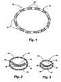
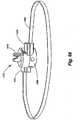
- an exemplary implant 10comprising an implant body 15 is shown in Fig. 1 .
- the implant body 10may be provided in a shape and size determined by the anatomic needs of an intended native recipient anatomic site within - a mammalian patient.
- a native recipient anatomic sitemay be, by way of illustration and not by way of limitation, a heart valve, the esophagus near the gastro-esophageal junction, the anus, or other anatomic sites within a mammalian body that are creating dysfunction that might be relieved by an implant capable of changing the size and shape of that site and maintaining a desired size and shape after surgery.
- the implantcan be used for positioning an aortic valve, a triple A device positioning, aortic stent grafting applications, aortic endograph applications, aortic triple A stent graphs, ascending aortic aneurysm repair, for stomach applications to control obesity and the like.
- the implant 10 of FIG. 1comprises a circular implant body 15 which is provided with adjustable corrugated sections 20 alternating with intervening grommet-like attachment means 25 having narrowed intermediate neck portions.
- the implant body 15may be secured to the annulus of a heart valve 30 by a fixation means such as a suture 35 secured over or through the attachment means 25.
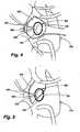
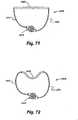
- the corrugated sections 20fold and unfold as the circumference of the implant body 15 shortens or lengthens. Adjustment of the implant 10 in situ may decrease the overall size of the heart valve 30, increasing the coaptation of the valve leaflets 40, and changing the configuration from that shown in FIG. 2 to that shown in FIG. 3 .
- FIGS. 4 and 5An additional exemplary embodiment 100 of the present invention is shown in FIGS. 4 and 5 , with an open operative cardiac incision 105 in a heart 110 shown in FIG. 4 , and closure of the cardiac incision 105 in FIG. 5 .
- the exemplary adjustable implant 100according to the present invention comprises an implant body 115 with attachment means 120 that allows fixation to the annulus of a mitral valve 125.
- the exemplary adjustable implant 100is further provided with an adjustment means 130 that is controlled boy an attached or coupled adjustment tool 135. After closure of the myocardial incision 105 in FIG.
- the adjustment tool 135remains attached or coupled to the adjustment means 130, so that the size and shape of the implant 100 may further be affected after physiologic flow through the heart 110 is resumed, but with the chest incision still open. Once the desired shape and function are achieved, the adjustment tool 135 may be disengaged from the adjustment means 130 and withdrawn from the myocardial incision 105.
- the adjustment means 130may be configured and placed to allow retention by or re-introduction of the adjustment tool 135 for adjustment following closure of the chest incision.
- the physicianmakes the open operative incision 105 in the heart 1 10, as shown in FIG. 4 , in the conventional manner.
- the implant 100mounted at the forward end of adjustment tool 135, is then advanced through the incision 105 and sutured to the annulus of the mitral valve 125.
- the adjustment tool 135is then manipulated, e.g., rotated, depending upon the design of the adjustment means 130, to cause the adjustment means to reduce the size of the implant body 115, and hence the underlying mitral valve 125 to which it is sutured, to an approximate size.
- the myocardial incision 105can now be closed, as shown in FIG. 5 , leaving the adjustment tool extending through the incision for post-operative adjustment.
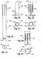
- FIGS. 6-8show an exemplary adjustment means 200 for adjusting the circumference of an annular implant such as the implant 100 previously described.
- the adjustment means 200comprises a rack and pinion system in which a first cam 205 with geared teeth 210 and an engagement coupler 215 turns on a first axel 220.
- the first cam 205engages a geared rack 225 on one or more surfaces of a first band 230.
- the first band 230passes between the first cam 205 and a second cam 235 that turns on a second axel 240 that is joined to a second band 245.
- the first and second axels 220, 240are maintained in suitable spaced-apart relation by means of a bracket 250 formed at the end of the second band 245.
- the adjustment means 200is preferably set within a hollow annular implant 100 of the type previously described, though it is possible to use the adjustment means in a stand-alone configuration wherein the first and second bands 230, 245 are opposing ends of the same continuous annular structure.
- a toolsuch as a hex wrench engages the engagement coupler 215 on the first cam 205 and rotates the first cam in a' counterclockwise direction as shown in FIG. 7 , as indicated by the arrow 255.
- Rotation of the first cam 205causes' the teeth 210 to drive the rack 225 to move the first band 230 toward the right, as indicated by the arrow 260 in FIG. 7 .
- This movement of the first bandtightens the circumference of the annular implant. If the physician inadvertently adjusts the implant too tight, reversing direction of the engagement coupler 215 will loosen the implant.
- the first and second bands 230, 245may be separate structures, or they may be opposing ends of the same continuous structure.
- the first cam 205is rotated, causing the geared teeth 210 to engage the geared rack 225, and causing the first band 239 to move with respect to the second band 245 to adjust the circumference of an implant.
- FIG. 9shows a somewhat different configuration of an exemplary engagement means 300 according to the present invention, in which there is no engagement coupler, and a bracket 350 is provided on both sides of the cams to maintain the first cam 315 and the second cam 320 in close approximation.
- the bracketis designed with close tolerances so as to press the first band 330 closely against the second band 345, thereby to hold the bands in fixed relative position by friction
- the brackets 350are fabricated from an elastic material such that the cams 315, 320 can be spread apart to insert the first band 330 between the cams, whereupon the cams are pulled back together with sufficient force to hold the bands 330, 345 in fixed relative position by friction.
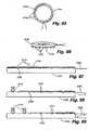
- FIG. 10shows an exemplary attachment means 400 for an implant according to the present invention.
- the attachment means 400could be used, for example, in place of the attachment means 25 of the implant 10.
- the attachment means 400takes the form of a grommet 410 comprising a wall 415 defining a lumen 420 and an attachment surface 425.
- Such an attachment meanswould be used with the implant body extending through the lumen 420 and with fixation devices such as sutures or wires either tied over or affixed through the attachment surface 425.
- FIG. 11shows another alternate embodiment of an attachment means 500 for an implant according to the present invention.
- the attachment means 500could also be used,, for example, in place of the attachment means 25 of the implant 10.
- FIG. 11shows an attachment means 500 in the form of a hollow tube or tube segment 510 comprising a wall 515 defining a lumen 520, an outer surface 525, and an attachment tab 530.
- fixation devicessuch as sutures or wires either tied or otherwise affixed over or through the attachment tab 530.
- fixation devicesmight be placed through holes 535 provided in the attachment tab 530.
- a solid attachment tab 530might be provided, and the fixation devices might be passed through the solid tab. Modifications of these attachment means may be used in conjunction with a sutureless attachment system.
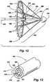
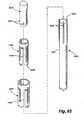
- FIGS. 12-18show another embodiment of a percutaneous annuloplasty device according to the present invention, in which an implant/delivery system array 600 includes a housing sheath 605 (not seen in FIG. 12 ), an actuating catheter 610 coaxially slidably mounted within the housing sheath 605, and a core catheter 615 coaxially slidably mounted within the actuating catheter 610.
- the core catheterhas a central lumen 616 ( FIG. 13 ).
- the actuating catheter 610 and core catheter 615may be round tubular structures, or as shown in FIG.
- either or both of the actuating and core cathetersmay be provided with one or more keyed ridges 618, 620 respectively to be received by one or more reciprocal slots 622, 624 within the inner lumen of either the housing sheath 665 or the actuating catheter 610, respectively.
- Such keyed ridges 618, 620would limit internal rotation of an inner element within an outer element, should such restriction be desirable to maintain control of the inner contents from inadvertent displacement due to undesired rotational motion during use.
- the implant/delivery system array 600includes a distal tip 625 at the forward end of the core catheter 615.
- One or more radial implant support arms 630have their distal ends 632 pivotably or bendably mounted to the core catheter 615 adjacent its distal tip 625.
- the proximal ends 634 of the radial implant support arms 630normally extend along the core catheter 615 but are capable of being displaced outward away from the core catheter.
- One or more radial support struts 636have their proximal ends 638 pivotably or bendably mounted to the distal end of the actuating catheter 610.
- the distal end 640 of each radial support strutis 636 pivotably or bendably attached to a midpoint of a corresponding radial implant support arm 630.
- the radial support struts 636force the radial implant support arms 630 upward and outward in the fashion of an umbrella frame.
- the actuating catheter 610, core catheter 615, radial support struts 636, and radial support arms 630in combination form a deployment umbrella 642.
- a prosthetic implant 645is releasably attached to the proximal ends 634 of the radial implant support arms 630.
- one or more of the radial implant support arms 630comprise touchdown sensors 648 whose proximal ends extend proximal to the implant 645. Extending through the central lumen 616 ( FIG. 13 ) of the core catheter 615 in the exemplary embodiment 600 and out lateral ports 650 ( FIG.
- release elements 660which serve to release the implant 645 from the delivery system
- adjustment elements 665which serve to adjust the implant's deployed size and effect. Because the release elements 660 and adjustment elements 665 extend through the proximal end of the core catheter 615, as seen in FIGS. 14-16 , these elements can be directly or indirectly instrumented or manipulated by the physician.
- a delivery interface 670( FIGS 12 , 16 ) is defined in this example by the interaction of the deployment umbrella 642, the release elements 660, and the implant 645.
- the release elements 660may be a suture, fiber, or wire in a continuous loop that passes through laser drilled bores in the implant 645 and in the radial implant support arms 630, and then passes through the length of the core catheter 615.
- the implant 645may be released from the delivery system at a desired time by severing the release element 660 at its proximal end, outside the patient, and then withdrawing the free end of the release element 660 through the core catheter 610.
- FIGS. 14-16show the operation of the implant/delivery system array 600, in which an umbrella-like expansion of the prosthetic implant 645 is achieved by sliding movement of the housing sheath 605, the actuating catheter 610, and the core catheter 615.
- the housing sheath 605is extended to cover the forward ends of the actuating catheter 610 and core catheter 615 for intravascular insertion of the implant/delivery system array 600.
- the housing sheath 605is retracted in the direction indicated by the arrows 662.
- FIG. 15the housing sheath 605 has been retracted to expose the forward end of the actuating catheter 610 and the collapsed deployment umbrella 642.
- FIG. 16shows the expansion of the deployment umbrella 642 produced by distal motion of the actuating catheter 610 relative to the core catheter 615.
- FIGS. 17 and 18are schematic views illustrating the radial implant support arms 630 and the radial support struts 636 of the implant/delivery system array 600.
- a radial support strut 636is pivotably attached at its proximal end 638 at a first pivotable joint 670 to the actuation catheter 610.
- the radial support strut 636is attached at its distal end 640 to a second pivotable joint 672 at an intermediate point of a corresponding radial implant support arm 630.
- the radial implant support arm 630is attached at its distal end 632 by a third pivotable joint 674 to the core catheter 620.
- FIG. 17shows the assembly in a closed state.
- FIGS. 19 and 20show further details of the touchdown sensors 648 shown previously in FIG. 12 .
- the touchdown sensor 648 of FIGS. 19 and 20includes a distal segment 680, an intermediate segment 682, and a proximal segment 684.
- the distal segment 680is spring-mounted, so that it is capable of slidable, telescoping displacement over the intermediate segment 682 to achieve a seamless junction with the proximal segment 684 upon maximal displacement.
- the springextends the proximal segment such that the sensor assumes the orientation shown in FIG. 19 .
- the implant 645FIG.
- the proximal segment 684 of the sensor 648is compressed against the distal segment 680, as shown in FIG. 20 .
- the distal segment 680 and the proximal segment 684are both constructed of, are sheathed by, or otherwise covered with a radio-opaque material.
- the intermediate segment 682is not constructed or coated with such a radio-opaque material. Therefore, when the distal segment 680 is at rest, it is fully extended from the proximal segment 684, and the gap represented by the exposed intermediate segment 682 is visible on radiographic examination.
- the touchdown sensoris said to be "activated".
- This embodimentallows radiographic monitoring of the position of the touchdown sensor 648 with respect to the degree of extension of the distal catheter segment 680.
- one or more touchdown detectors 648are employed to ascertain that the delivery system for the prosthetic device is located in the proper position to deploy the implant into the mitral annulus. As this anatomic structure cannot be directly identified on fluoroscopy or standard radiographic procedures, such precise location could be otherwise difficult. At the same time, precise localization and engagement of the mitral annulus is critical for proper implant function and safety.
- Touchdown detectors within the embodiments according to the present inventioncan have a multiplicity of forms, including the telescoping, spring-loaded, radio-opaque elements joined by a non-radio-opaque element as in the aforementioned examples.
- touchdown detectors according to the present inventionmay utilize metallic segments interposed by nonmetallic segments in a similar telescoping, spring-loaded array.
- Other embodimentsinclude a visually-evident system with telescoping, spring-loaded elements with color-coded or other visual features for procedures in which direct or endoscopic observation would be possible.
- touchdown detectorsinclude touchdown detectors provided with microswitches at their tips, such that momentary contact of sufficient pressure completes an electrical circuit and signals the activation of the touchdown detector to the operator.
- Still other touchdown detectors according to the present inventionare provided with fiberoptic pathways for compassion laser spectroscopy or other spectral analytical techniques which are capable of detecting unique tissue qualities of the tissue at the desired site for implantation.
- still other embodiments according to the present inventioninclude touchdown detectors containing electrodes or other electronic sensors capable of detecting and signaling the operator when a desired electrophysiologic, impedance, or other measurable quality of the desired tissue is detected for proper implantation.
- Such electrophysiologic touchdown detectorsmay include electrical circuits that produce visual, auditory, or other signals to the operator that the detectors are activated and that the implant is in the proper position for attachment.
- intracardiac or extracardiac imaging techniquesincluding, but not limited to, intravascular ultrasound, nuclear magnetic resonance, virtual anatomic positioning systems, or other imaging techniques may be employed to confirm proper positioning of the implant, obviating the need for the touchdown sensors as previously described.
- FIGS. 21-24show an implant 700 according to one embodiment of the present invention.
- the implant body 705is bandlike and flexible. Through much of its length, the implant body 705 is provided with a series of retention barbs 710 which are oriented to facilitate placement, retention, and removal of the device.
- the implant body 705is also provided with an adjustable section 715, which is provided in this example with a series of adjustment stops 720.
- the adjustment stops 720may be slots, holes, detents, dimples, ridges, teeth, raised elements, or other mechanical features to allow measured adjustment of the implant 700 in use. In the embodiment shown in FIGS. 21-24 , the adjustment stops 720 are engaged by a geared connector 725.
- FIG. 21is an end view, showing the implant body 705 curved on itself, with the retention barbs 710 to the exterior, and with the adjustable section 715 passing through its engagement with the geared connector 725 and curving internally within the implant body 705 to form a closed, round structure.
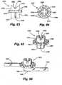
- FIG. 23shows details of an exemplary geared connector 725, in which a housing 730 is connected to the implant body 705.
- the housing 730contains and supports a mechanical worm 740 with an attached first geared head 750 which mates with a second geared head 755.
- the second geared head 755is attached to an adjustment stem 760 which is machined to receive a screwdriver-like adjustment element.
- the various embodiments according to the present inventionmay require a number of forms of adjustment elements.
- the adjustment elementis provided as a finely coiled wire with a distal tip machined to be received by a receiving slot in the adjustment stem 760 (not shown).
- the relationship between the distal tip of the adjustment element and the adjustment stem 760is mechanically similar to a screwdriver bit and screwhead, such that torsion imparted to the adjustment means by the operator will result in the turning of the adjustment stem 760 and second geared bead 755 allows motion of the first geared head 750 and worm 740, which creates motion of the adjustable implant section 715 as the worm engages with the series of adjustment tops 725. Excess length of the adjustable section 715 passes though a band slot 735 ( FIG.
- the adjustment element in this embodimentmay be designed to remain in place after the deployment umbrella has been retracted and withdrawn.
- the connection between the adjustment element's distal tip and the adjustment stem 760may be a simple friction connection, a mechanical key/slot formation, or may be magnetically or electronically maintained.
- the exemplary embodimentemploys unidirectional retention barbs 710 which are attached to the outer perimeter of the implant body 705.
- the retention barbs 710are oriented in a consistent, tangential position with respect to the implant body 705 such that rotational motion of the implant body will either engage or release the retention barbs 710 upon contact with the desired tissue at the time of deployment.
- This positioning of the retention barbs 710allows the operator to "screw in” the implant 700 by turning the implant 700 upon its axis, thus engaging the retention barbs 710 into the adjacent tissue. As shown in FIG.
- the retention barbs 710may each be further provided with a terminal book 775 at the end which would allow for smooth passage through tissue when engaging the retention barbs 710 by rotating the implant 700, without permitting the implant 700 to rotate in the opposite direction, because of the action of the terminal books 775 grasping the surrounding tissue (much like barbed fish books).
- the terminal books 775thus ensure the seating of the implant 700 into the surrounding tissue.
- FIGS. 25-27illustrate another embodiment of an implant 800 as contemplated according to the present invention.
- the implant 800includes a band 805 ( FIG. 27 ), but the retention barbs of the previous example have been eliminated in favor of an outer fabric implant sheath 810.
- the fabric sheath 810can be sutured or otherwise affixed to the anatomic tissue in a desired location.
- the circumference of the implant body 800is adjusted through a geared connector 825 similar to the geared connector of the bandlike implant array shown in FIG. 23 . More specifically, adjustment stops 820 on the band are engaged by a mechanical worm 840 with an attached first geared bead 850.
- the first geared head 850mates with a second geared head 855.
- the second geared bead 855is attached to an adjustment stem 860 which is machined to receive a screwdriver-like adjustment element.
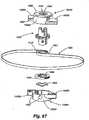
- FIG. 28illustrates an example of the method of use of an implant/delivery system array 600 for positioning an implant 645 in a patient with ischemic annular dilatation and mitral regurgitation.
- Peripheral arterial accessis obtained via conventional cutdown, arterial puncture, or other standard access techniques.
- guidewire placementis per-formed and intravascular access to the heart, 900 is obtained using fluoroscopic, ultrasound, three-dimension ultrasound, magnetic resonance, or other real-time imaging techniques.
- the guidewire, deployment device,, and implantare passed through the aortic valve in a retrograde fashion into the left ventricle 905 and then into the left atrium 910.
- the operatorretracts the housing sheath 605, thus unsheathing the collapsed deployment umbrella 642 and implant 645.
- the deployment umbrella 642is then distended by the distal motion of the actuation catheter, causing the radial support arms and struts to fully distend.
- the touchdown detectors 648are not in contact with any solid structures, and are fully extended with their radiolucent gaps visible on the imaging system. Once the deployment umbrella is distended, the entire assembly is pulled back against the area of the mitral valve 915. At least two touchdown detectors 648 are employed in a preferred embodiment according to the present invention.
- the deployment umbrellaWhen all touchdown detectors show the disappearance of their intermediate, non-opaque, intermediate segments and are thus activated, then the deployment umbrella must be in contact with the solid tissue in the region of the mitral annulus/atrial tissue, and further implant deployment and adjustment may proceed. However, if any one touchdown sensor is not activated, and a radiolucent gap persists, then the device is not properly positioned, and must be repositioned before further deployment. Thus, the touchdown sensor system may assist in the deployment and adjustment of prosthetic devices by the delivery system according to the present invention. Once properly positioned, the operator rotates the actuation catheter in a prescribed clockwise or counterclockwise manner to engage the retention barbs on the implant into the tissue in the region of the mitral annulus/atrial tissue.
- the adjustment element(s)are operated to achieve the desired degree of annular reduction.
- Real-time trans esophageal echocardiography, intravascular echocardiography, intracardiac echocardiography, or other modalities for assessing mitral functionmay then be employed to assess the physiologic effect of the repair on mitral function, and additional adjustments may be performed.
- the release elementsare activated to detach the implant from the deployment umbrella. The operator then retracts the actuation catheter and extends the housing sheath, collapsing the deployment umbrella, and covering the components for a smooth and atraumatic withdrawal of the device from the heart and vascular system.
- the adjustment elementsmay be left in position after the catheter components are withdrawn for further physiologic adjustment.
- a catheter-based adjustment elementsmay subsequently be re-inserted though a percutaneous or other route.
- Such an adjustment elementmay be steerably operable by the operator, and may be provided with magnetic, electronic, electromagnetic, or laser-guided systems to allow docking of the adjustment element with the adjustable mechanism contained within the implant.
- the adjustment mechanismmay be driven by implanted electromechanical motors or other systems, which may be remotely controlled by electronic flux or other remote transcutaneous or percutaneous methods.
- initial catheter accessis achieved through a peripheral or central vein.
- Access to the pulmonary valveis also achieved from below the valve once central venous access is achieved by traversing the right atrium, the tricuspid valve, the right ventricle, and subsequently reaching the pulmonic valve.
- catheter access to the left atriumcan be achieved from cannulation of central or peripheral veins, thereby achieving access to the right atrium.
- a standard atrial trans-septal approachmay be utilized to access the left atrium by creation of an iatrogenic atrial septal defect (ASD).
- the mitral valvemay be accessed from above the valve, as opposed to the retrograde access described in Example 1.
- the implant and a reversed deployment umbrellamay be utilized with implant placement in the atrial aspect of the mitral annulus, with the same repair technique described previously.
- the iatrogenic ASDmay then be closed using standard device methods.
- Access to the aortic valvemay also be achieved from above the aortic valve via arterial access in a similar retrograde fashion.
- gastrointestinal disorderssuch as gastroesophageal reflux disease (GERD), a condition in which the gastro-esophageal (GE) junction lacks adequate sphincter tone to prevent the reflux of stomach contents into the esophagus, causing classic heartburn or acid reflux.
- GFDgastroesophageal reflux disease
- GEgastro-esophageal
- GEgastro-esophageal
- Thisnot only results in discomfort, but may cause trauma to the lower esophagus overtime that may lead to the development of pre-cancerous lesions (Barrett's esophagus) or adenocarcinoma of the esophagus at the GE junction.
- Surgical repair of the GE junctionhas historically been achieved with the Nissen Fundoplication, an operative procedure with, generally good results.
- an adjustable implantwould obviate the need for a hospital stay and be performed in a clinic or gastroenterologist's office.
- an umbrella deployment device 600 with implant 645is passed under guidance of an endoscope 1000, through the patient's mouth, esophagus 1005, and into the stomach 1010, where the deployment device 600 is opened with expansion of the implant 645 and touchdown detectors 648 with a color-coded or otherwise visible gap.
- the touchdown detectorsare then engaged onto the stomach around the gastroesophageal junction 1015 under direct endoscopic control until all touchdown detectors 648 are visually activated.
- the implantis then attached to the stomach wail, 1020 the umbrella 642 is released and withdrawn, leaving behind the implant 645 and the adjustment elements.
- the implantis then adjusted until the desired effect is achieved, i.e., minimal acid reflux either by patient symptoms, pH monitoring of the esophagus, imaging studies, or other diagnostic means. If the patient should suffer from gas bloat, a common complication of gastroesophageal junction repair in which the repair is too tight and the patient is unable to belch, the implant can be loosened until a more desirable effect is achieved.
- the implant bodymay be straight, curved, circular, ovoid, polygonal, or some combination thereof.
- the implantmay be capable of providing a uniform or non-uniform adjustment of an orifice or lumen within the body.
- the implant bodymay further completely enclose the native recipient anatomic site, or it may be provided in an interrupted form that encloses only a portion of the native recipient anatomic site.
- the implant bodymay be a solid structure, while in yet other embodiments the- implant body may form a tubular or otherwise hollow structure.
- the bodymay further be a structure with an outer member, an inner member, and optional attachment members.
- the outer member of the implant bodymay serve as a covering for the implant; and is designed to facilitate and promote tissue ingrowth and biologic integration to the native recipient anatomic site.
- the outer member in such an embodimentmay be fabricated of a biologically compatible material, such as Dacron, PTFE, malleable metals,, other biologically compatible materials or a combination of such biologically compatible materials in a molded, woven, or non-woven configuration.
- the outer member in such an embodimentalso serves to house the inner member.
- the inner memberprovides an adjustment means that, when operated by an adjustment mechanism, is capable of altering the shape and/or size of the outer member in a defined manner.
- the adjustment meansmay be located external to or incorporated within the outer member.
- the implant bodymay consist of an adjustment means without a separate outer member covering said adjustment means.
- the adjustment meansmay include a mechanism which may be threaded or nonthreaded, and which may be engaged by the action of a screw or worm screw, a friction mechanism, a friction-detent mechanism, a toothed mechanism, a ratchet mechanism, a rack and pinion mechanism, or such other devices to permit discreet adjustment and retention of desired size a desired position, once the proper size is determined.
- the adjustment meansmay comprise a snare or purse string-like mechanism in which a suture, a band, a wire or other fiber structure, braided or non-braided, monofilament or multifilament, is capable of affecting the anatomic and/or physiologic effects of the implant device on a native anatomic recipient site upon varying tension or motion imparted to said wire or fiber structure by a surgeon or other operator.
- Such an adjustment meansmay be provided as a circular or non-circular structure in various embodiments. Changes in tension or motion may change the size and/or shape of the implant.
- the adjustment meansmay be a metallic, plastic, synthetic, natural, biologic, or any other biologically-compatible material, or combination thereof. Such adjustment means may further be fabricated by extrusion or other molding techniques, machined, or woven. Furthermore, in various embodiments of the present invention, the adjustment means may be smooth or may include slots, beads, ridges, or any other smooth or textured surface.
- the implant bodymay be provided with one or more attachment members such as grommets or openings or other attachment members to facilitate attachment of the implant to the native recipient site.
- the implant bodymay attach to or incorporate a mechanical tissue interface system that allows a sutureless mechanical means of securing the implant at the native recipient site.
- sutures or other attachment meansmay be secured around or through the implant body to affix the implant body to the native recipient site,
- mechanical means of securing the implant body to the native recipient sitemay be augmented or replaced by use of fibrin or other biologically-compatible tissue gives or similar adhesives.
- the adjustable implantmay be employed to adjustably enlarge or maintain the circumference or other dimensions of an orifice, ostium, lumen, or anastomosis in which a disease process tends to narrow or constrict such circumference or other dimensions.
- an adjustment mechanismmay be provided to interact with the adjustment means to achieve the desired alteration in the size and/or position of the adjustment means.
- Such an adjustment mechanismmay include one or more screws, worm-screw arrays rollers, gears, frictional stops, a friction-detent system, ratchets, rack and pinion arrays, micro-electromechanical systems, other mechanical or electromechanical devices or some combination thereof.
- an adjustment too]may be removably or permanently attached to the adjustment mechanism and disposed to impart motion to the adjustment mechanism and, in turn, to the adjustment means to increase or decrease the anatomic effect of the implant on the native recipient site.
- micromotor arrays with one or more micro-electromechanical motor systems with related electronic control circuitrymay be provided, as an adjustment means, and may be activated by remote control through signals convey by electromagnetic radiation or by direct circuitry though electronic conduit leads which may be either permanently or removably attached to said micromotor arrays.
- the adjustment mechanismmay be provided with a locking mechanism disposed to maintain the position of the adjustment means in a selected position upon achievement of the optimally desired anatomic and/or physiologic effect upon the native recipient site and the bodily organ to which it belongs.
- no special locking mechanismmay be necessary due to the nature of the adjustment means employed.
- the adjustment means and/or the outer member structuremay be a pliable synthetic material capable of rigidification upon exposure to electromagnetic radiation of selected wavelength, such as ultraviolet light.
- exposure to the desired electromagnetic radiationmay be achieved by external delivery of such radiation to the implant by the surgeon, or by internal delivery of such radiation within an outer implant member using fiberoptic carriers placed within said outer member and connected to an appropriate external radiation source.
- fiberoptic carriersmay be disposed for their removal in whole or in part from the outer implant member after suitable radiation exposure and hardening of said adjustment means.
- the present inventionalso provides methods of using an adjustable implant device to selectively alter the anatomic structure and/or physiologic effects of tissues forming a passageway for blood, other bodily fluids, nutrient fluids, semi-solids, or solids, or wastes within a mammalian body.
- adjustable implantsinclude, but are not limited to, open surgical placement of said adjustable implants at the native recipient site through an open surgical incision, percutaneous or intravascular placement of said implants under visual control employing fluoroscopic, ultrasound, magnetic resonance imaging, or other imaging technologies, placement of said implants through tissue structural walls, such as the coronary sinus or esophageal walls, or methods employing some combination of the above techniques.
- adjustable implantsmay be placed and affixed in position in a native recipient anatomic site by trans-atrial, trans-ventricular, trans-arterial, trans-venous (i.e., via the pulmonary veins) or other routes during beating or non-beating cardiac surgical procedures or endoscopically or percutaneously in gastrointestinal surgery.
- alternate methods for use of an adjustable implant devicemay provide for the periodic, post-implantation adjustment of the size of the anatomic structure receiving said implant device as needed to accommodate growth of the native recipient site in a juvenile patient or other changes in the physiologic needs of the recipient patient.
- Adjustment of the adjustable implants and the methods for their use as disclosed hereincontemplates the use by the surgeon or operator of diagnostic tools to provide an assessment of the nature of adjustment needed to achieve a desired effect.
- diagnostic toolsinclude, but are not limited to, transesophageal echocardiography, echocardiography, diagnostic ultrasound, intravascular ultrasound, virtual anatomic positioning systems integrated with magnetic resonance, computerized tomographic, or other imaging technologies, endoscopy, mediastinoscopy, laparoscopy, thoracoscopy, radiography, fluoroscopy, magnetic resonance imaging, computerized tomographic imaging, intravascular flow sensors, thermal sensors or imaging, remote chemical or spectral analysis, or other imaging or quantitative or qualitative analytic systems.
- the implant/delivery system of the present inventioncomprises a collapsible, compressible, or distensible prosthetic implant and a delivery interface for such a prosthetic implant that is capable of delivering the prosthetic implant to a desired anatomic recipient site in a collapsed, compressed, or non-distended state, and then allowing controlled expansion or distension and physical attachment of such a prosthetic implant by a user at the desired anatomic recipient site.
- Such a systempermits the delivery system and prosthetic implant to be introduced percutaneously through a trocar, sheath, via Seldinger technique, needle, or endoscopically through a natural bodily orifice, body cavity, or region and maneuvered by the surgeon or operator to the desired anatomic recipient site, where the delivery system and prosthetic implant may be operably expanded for deployment.
- the implant/delivery system according to the present inventionis also capable of allowing the user to further adjust the size or shape of the prosthetic implant once it has been attached to the desired anatomic recipient site.
- the delivery system according to the present inventionis then capable of detaching from its interface with the prosthetic implant and being removed from the anatomic site by the operator.
- the delivery system and prosthetic implantmay be provided in a shape and size determined by the anatomic needs of an intended native recipient anatomic site within a mammalian patient.
- a native recipient anatomic sitemay be a heart valve, the esophagus near the gastro-esophageal junction, the anus, or other anatomic sites within a mammalian body that are creating dysfunction that might be relieved by an implant capable of changing the size and shape of that site and maintaining a desired size and shape after surgery.
- the delivery systemmay be a catheter, wire, filament, rod, tube, endoscope, or other mechanism capable of reaching the desired recipient anatomic site through an incision, puncture, trocar, or through an anatomic passageway such as a vessel, orifice, or organ lumen, or trans-abdominally or trans-thoracically.
- the delivery systemmay be steerable by the operator.
- the delivery systemmay further have a delivery interface that would retain and convey a prosthetic implant to the desired recipient anatomic site.
- Such a delivery interfacemay be operably capable of distending, reshaping, or allowing the independent distension or expansion of such a prosthetic implant at the desired recipient anatomic site.
- such a delivery interfacemay provide an operable means to adjust the distended or expanded size, shape, or physiologic effect of the prosthetic implant once said implant has been attached in situ at the desired recipient anatomic site.
- such adjustmentmay be carried out during the procedure in which the implant is placed, or at a subsequent time.
- the delivery interface and the associated prosthetic implantmay be straight, curved, circular, helical, tubular, ovoid, polygonal, or some combination thereof.
- the prosthetic implantmay be a solid structure, while in yet other embodiments the prosthetic implant may form a tubular, composite, or otherwise hollow structure.
- the prosthetic implantmay further be a structure with an outer member, an inner member, and optional attachment members.
- the outer member of the prosthetic implantmay serve as a covering for the implant, and is designed to facilitate and promote tissue ingrowth and biologic integration to the native recipient anatomic site.
- the outer member in such an embodimentmay be fabricated of a biologically compatible material, such as Dacron, PTFE, malleable metals, other biologically compatible materials or a combination of such biologically compatible materials in a molded, woven, or non-woven configuration.
- the outer member in such an embodimentalso serves to house the inner member.
- the inner memberprovides an adjustment means that, when operated by an adjustment mechanism, is capable of altering the shape and/or size of the outer member in a defined manner.
- At least some portions of the adjustable inner or outer membermay be elastic to provide an element of variable, artificial muscle tone to a valve, sphincter, orifice, or lumen in settings where such variability would be functionally valuable, such as in the treatment of rectal incontinence or vaginal prolapse.
- the delivery interfacewould have an attachment means to retain and convey the prosthetic implant en route to the native anatomic recipient site and during any in situ adjustment of the prosthetic implant once it has been placed by the operator.
- Such an attachment meanswould be operably reversible to allow detachment of the prosthetic implant from the delivery interface once desired placement and adjustment of the prosthetic implant has been accomplished.
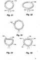
- FIGS. 31-39illustrate various embodiments of a ring in its relaxed condition.
- Figure 31illustrates a circular ring 1110 having drawstrings 1111, 1112 extending from a lower portion thereof.
- Figure 32illustrates an oval ring 130 having drawstrings 1121, 1122.
- Figure 33depicts a hexagonal ring 1130.
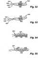
- Figure 34illustrates a ring 1140 in the shape of a partial circle 1145 with a straight leg 1146 connecting the two ends of the partial circle.
- Figure 35shows a ring 1150 comprising an arcuate portion 1154 and three -straight leg portions 1155-1157 connecting the two ends of the arc.
- Figure 36shows a curvilinear ring 1160 having a convex portion 1164 on one side and a concave portion 1166 on the other.
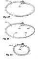
- Figure 37depicts a curvilinear ring 1170 which is concave on both sides 1174, 1176.
- Figure 38illustrates a ring 1180 which is generally circular in shape and has an opening 1184 in its upper end.
- Figure 39shows a ring comprising an arcuate portion 1194 and straight legs 1195, 1196 extending toward one another but leaving an opening 1197 therebetween.
- Figures 40 and 41show the ring 1110 cut away to show the drawstrings 1111, 1112.
- the entire ring 10is adjusted smaller.
- drawstrings 1111, 1112can be freely slidable within the ring 1110, rather than anchored, with largely the same effect).
- the ring 1110A of figures 42 and 43is only partially adjustable.
- the ends of the drawstrings 1111A, 1112Ado not meet but rather are anchored at locations 1113A, 1113B around the ring 1110A.
- the segments 1117A, 1117B through which the drawstrings extendare the sections which are most adjusted.
- the section 1118A, through which no portion of either drawstring extendsreceives relatively little adjustment.
- Figures 44-47illustrate the effect of internal reinforcement on the adjustability of a ring.
- a ring 1140has no internal reinforcement. Consequently, when the drawstrings 1141, 1142 are tensioned, the entire ring 1140 adjusts.
- the ring 1140A of figures 46 and 47has a reinforcing element 1144A extending through the straight leg 1146A of the ring.
- the reinforcing element 1144Ais a hollow tube.
- the reinforcing element 1144Acan assume other configurations, including a solid rod of suitable cross-section.
- the drawstrings 1141A, 1142Aare anchored to the ends of the reinforcing element 1144A.
- drawstringscan extend through the tube, either to be anchored at a common location inside the tube or to be freely slidable within the tube.
- the drawstringscan extend alongside the reinforcing element 1144A, either to be anchored at a common location alongside the reinforcing element or to be freely slidable alongside the reinforcing element.
- Figures 48-51illustrate the use of internal shaping members operatively associated with the drawstrings such that when the drawstrings are tensioned, the shaping members cause the ring to assume a predetermined configuration.
- a generally circular ring 1200has a plurality of wedge-shaped shaping members 1201 disposed within the ring.
- the left drawstring 1202is connected to the right-most shaping number 1201A
- the right drawstring 1203is connected to the left-most shaping number 1201B.
- the right-most shaping member 1201 A and the left-most shaping member 1201 Bare drawn toward one another. This movement of the outermost shaping members causes the wedge surfaces of each shaping number 1201 to confront the wedge surfaces of the adjacent shaping members, forcing the group of shaping members to assume the concave configuration illustrated in figure 49 .
- shaping members 1201 of the embodiment of figures 48 and 49are configured to assume a concave configuration when the drawstrings are cinched, it will be appreciated that the configuration of the shaping members may be designed such that the group forms a convex configuration, a straight line, a serpentine configuration with both convex and concave portions, or any other desired geometric shape.
- a generally circular ring 1210has two groups 1212, 1213 of wedge-shaped shaping members 1211.
- the ring 1210comprises four drawstrings, a pair of drawstrings being associated with each of the two groups 1212, 1213 of wedge-shaped shaping members 1211.
- the first drawstring 1214extends around the ring 1210 in a clockwise direction and is connected to the uppermost member 1211A of the first group 1212 of shaping members 1211.
- the second drawstring 1215extends around the ring 1210 in a counterclockwise direction and is connected to the lowermost member 1211B of the first group 1212 of shaping members 1211.
- the third drawstring 1216extends around the ring 1210 in a clockwise direction and is connected to the lowermost member 1211C of the second group 1213 of shaping members 1211, while the fourth drawstring 1217 extends around the ring in a counterclockwise direction and is connected to the uppermost member 1211 D of the second group 1213 of shaping members.
- the first group 1212 of shaping members 1211is drawn together, and the second group 1213 of shaping members is drawn together.
- the two groups 1212, 1213 of members 1211assume predetermined geometric shapes, causing the ring 1210 to assume the ovoid configuration shown in figure 51 .
- the two groups of shaping members in the embodiment of figures 50 and 51form identical geometric shapes, it will be understood that the configuration of the shaping members may be designed such that each group forms a different shape.
- the two groups of shaping members in the embodiment of figures 50 and 51form convex geometric shapes, it will be appreciated that the shaping members can be configured to assume a concave shape, a straight line, or a serpentine shape comprising both convex and concave sections, or any combination of these and other shapes.
- a ring 1220comprises a plurality of shaping members 1221 formed into two groups 1222, 1223. With the ring lying flat, the shaping members are narrower at the top than at the bottom. Thus, when the drawstrings 1224-1227 are cinched, the ring bows upward into the saddle-shaped configuration depicted in figure 53 .
- Figures 54 and 55illustrate an embodiment of a ring 1230 comprising a variety of differently configured shaping members 1231. Only some of the shaping members 1231 are shown in Figures 54 and 55 for clarity of illustration.
- the shaping members 1231are arranged in alternating groups 1232 of shaping members narrower at the top than at the bottom and groups 1233 of shaping members narrower at the bottom than at the top. Utilizing the principles previously explained, it will be seen that, by having some shaping members narrower at the top that the bottom and some shaping members narrower at the bottom than at the top, complex three-dimensional configurations can be achieved.
- the ringscan be curvilinear ( figures 31, 32 , and 36-38 ), rectilinear ( figure 33 ), or a combination of straight and curved segments ( figures 34, 35 , and 39 ).
- the ringcan be either entirely closed ( figures 31-37 ) or partially closed ( figures 38 and 39 ).
- the ringscan be fully adjustable ( figures 40, 41 , 44, and 45 ) or partially adjustable ( figures 42, 43 , 46, and 47 ).
- the ringscan be unreinforced ( figures 31-45 ) or reinforced ( figures 46 and 47 ).
- the ringscan contain shaping members that assume a specific geometric configuration in two dimensions ( figures 48-51 ) or three dimensions ( figures 52-55 ).
- FIGS. 31-55all employ drawstrings as a means for adjusting the circumference of the implants. and are not embodiments of the invention.
- a different approachis taken in the embodiment of the invention of FIGS. 56-70 , in which an adjustable implant employs a winch to take up or to let out the circumference of the ring.
- a system 1300 for adjusting the configuration of a mitral valve annulusincludes an adjustable ring 1310, a drive unit 1312, and a winch 1314 (largely hidden within the lower end of the drive unit 1312 in FIG. 56 ). Each of these components will now be discussed in more detail.
- the ring 1310is at its maximum circumference and is coupled to the winch 1314 at each end.
- the ring 1310comprises an outer layer 1320 of Dacron.
- the ring 1310is cut away to reveal an intermediate layer 1322 and a band 1324 of nitinol or other suitable flexible, nonextensible material.
- FIG. 59shows the ring 1310 in a contracted state.
- Figure 60illustrates the distal portion of a drive shaft 1330 of the drive unit 1310.
- the drive, shaft 1330is of indeterminate length but is advantageously long enough to extend to a location outside the patient, while at the same time being as short as possible to facilitate transmission of torque along the length of the shaft 1330.
- the drive shaft 1330is preferably a solid, flexible rod of circular cross-section, but it will be understood that other suitable shapes, including hollow tubes, or rods of cross-section other than circular, can be employed.
- the drive shafthas a winch-engaging member 1332 at its distal end 1334.
- the wench-engaging member 1332takes the form of a flat-blade screwdriver tip.
- other suitable tip configurationscan be used to cooperatively engage the wench 1314, including, but not limited to, a Philips head tip, a hex head tip, a wrench socket, and the like.
- Spaced proximally up the drive shaft 1330 from the distal end. 1334is a circumferential groove 1336.
- Figure 61depicts the distal portion of an inner tube 1340 of the drive unit 131 0.
- the inner tube at 1340is comprised of a flexible material.
- the inner tube 1340has a lumen 1342 slightly larger than the outer diameter of the drive shaft 1330 such that the drive shaft can rotate freely within the inner tube 1340.
- a pair of openings 1346dimensioned to clear portions of the winch 1320.
- a pair of axially-extending slots 1348are also at the distal end 1344 of the inner tube 1340, which permit the distal end 1344 of the inner tube 1340 to expand slightly.
- a plurality of inwardly projecting protrusions 1350Spaced around the periphery of the lumen, 1342 just proximal of the distal end 1344 of the inner tube 1340 are a plurality of inwardly projecting protrusions 1350. Just proximal of the proximal ends of the slots 1348 is an inwardly extending annular ring 1352 (not shown in Figure 61 ; see FIGS. 69 , 70 ).
- Figure 62shows the drive shaft 1330 disposed within the inner tube 1340-
- the distal end of the drive shaft 1330is recessed within the distal end of the inner tube 1340.
- the annular ring 1352 ( Figures 69 , 70 ) of the inner tube 1340engages the circumferential groove 1336 of the drive shaft 1330 to retain the drive shaft and inner tube in predetermined axial relation.
- the final component of the drive unit 13 10is an outer tube 1360 ( FIGS. 69 , 70 ) of a flexible, resilient material.
- the outer rube 1360has a lumen dimensioned to receive the inner tube 1340 therewithin, for a purpose which will be explained herein below.
- FIG. 63-65illustrate a spindle 1370 of the winch 1320.
- the spindle 1370has an upper end 1372, a lower end 1374, and a disk 1376 intermediate the upper and lower ends.
- the upper end 1372 of the spindle 1370comprises a drive-shaft engagement means 1378, which in the disclosed embodiment comprises a pair of transverse slots 1380 dimensioned to receive the flat-blade screwdriver tip 1332 of the drive shaft 1330 ( FIG. 60 ).
- the portions of the spindle 1370 between the slots 1380are beveled to form facets 1382 which direct the flat-blade screwdriver tip 1332 of the drive shaft into the slots.
- a generally cylindrically shaped body 1384In the disclosed embodiment the cylindrical body 1384 is hollow to save material, but it will be understood that a solid cylindrical body is also suitable. At the lower end 1374 of the spindle 1370, slots 1386 are formed to extend in a generally axial direction.
- the upper surface of the disk 1376comprises a plurality of recesses 1398, the purpose of which will be explained below.
- FIG. 66shows a section of the band 1324 of the ring 1310 received within the slots 1386 and wrapped around the cylindrical body 1384 of the spindle 1370.
- the winch 1312comprises a housing 1390 consisting of upper and lower housing halves 1390A, 1390B.
- the upper and lower housing halves 1390A, 1390Bare preferably formed with cooperating pins and holes to facilitate in aligning and mating the housing halves.
- a circular opening 1394is formed in the upper end 1392 of the upper housing half 1390A.
- a plurality of teeth 1396Surrounding the circular opening 1394 and protruding downward from the inner surface of the upper housing half 1390A are a plurality of teeth 1396.
- the edges 1397 of the upper surface 1392are beveled.
- the upper and lower housing halves 1390A, 1390Beach comprise a generally cylindrical portion 1398A, 1398B and tangentially extending sleeve portions 1400A, 1400B.
- the outer periphery of the lower housing half 1390Bhas a plurality of dimples 1402 formed therein. Seated within the lower housing half 1390B is a wave spring 1404. A washer 1406 with an annular recess 1408 formed in its upper surface sits atop the wave spring 1404. A portion of the band 1324 of the ring 1310 is received within the slots 13 86 in the lower end 1374 of the spindle 1370, and the lower end 1374 of the spindle rests within the annular recess 1408 in the upper surface of the washer 1406. Portions 1410, 1412 of the band 1324 adjacent the spindle 1370 are seated within the tangentially extending -sleeve portions 1400B of the lower housing half.
- the upper housing half 1390Ais then assembled onto the lower housing half 1390B.
- the upper end 1372 of the spindle 1370extends through the circular opening 1394 in the upper housing half 1390A such that the drive-shaft engagement means 1378 resides outside the housing 1390.
- the band 1324exits the housing 1390 through the tangentially extending sleeves 1400 such that the major portion of the band resides outside the winch housing.
- FIG. 69illustrates the engagement of the drive unit 1312 with the winch 1314.
- the winch 1314is in a self-locked state. This state is achieved by the wave spring 1404 urging the washer 1406 upward, which in turn forces the spindle 1370 upward against the top interior surface of the winch housing 1390.
- the teeth 1396extending downward from the top interior surface of the housing engage the recesses 1386 in the upper surface of the disk 1376 of the spindle 1370, preventing rotation of the spindle.
- the inner edges of the distal end 1344 of the inner tube 1340confront the beveled outer edges of the upper end 1392 of the housing 1390 and spread the distal end of the inner tube.
- the tangential sleeves 1400 ( FIG. 68 ) of the winch housing 1390are received within the openings 1346 ( FIG. 61 ) in the distal end 1344 of the inner tube 1340.
- the inwardly projecting protrusions 1350 within the distal end 1344 of the inner tubeengage the dimples 1402 in the lower outer portion of the winch housing 1390 to lock the drive unit 1312 to the winch 1314.
- the blade 1332 of the drive shaft 1330confronts the beveled facets 1382 and is directed into one of the slots 1380.
- the spindle 1370is forced downward, flattening the wave spring 1404 and disengaging the recesses 1386 in the upper surface of the disk 1376 of the spindle from the teeth 1396 on the interior upper surface of the winch housing 1390.
- the spindlecan now be turned.
- the band(not shown in FIGS. 69-70 ) wraps around the spindle 1370 as the drive shaft 1330 is turned, shortening the length of the band outside the winch housing 1390.
- the drive unit 1312is disengaged from the winch 1314.
- the outer tube 1360is advanced until it confronts the tangential sleeves 1400 ( FIG. 68 ) of the winch housing 1390.
- the outer tube 1360is then used to hold the winch 1314 and ring 13 10 in place while the inner tube 1340 is retracted.
- the protrusions 1350 within the distal end 1344 of the inner tubedisengage from the dimples 1,402 in the lower outer portion of the winch housing 1390.
- the drive shaft 1330releases its downward pressure on the spindle 1370.
- the wave spring 1404returns to its normal, uncompressed condition, biasing the spindle 1370 upward so that the teeth 1396 on the interior upper surface of the winch housing 1390 once again engage the cooperating recesses 1386 in the upper surface of the disk 1376.
- the spindle 1370is now prevented from rotating, thereby locking the winch 1314 and fixing the exposed length of the ring 1310.
- the use of the device 1300 to reconfigure a mitral valve annuluswill now be described.
- the heartis opened, and the ring 1310 is sutured around the mitral valve annulus, placing stitches through the fabric outer layer 1320 and the adjacent tissue.
- the drive unit 1312is coupled to the winch 1314, and preliminary adjustment of the ring is effected.
- the heartis now closed, and the patient is taken off bypass.
- final adjustment of the ringcan be effected via the drive unit, checking for reflux by suitable medical visualization means.
- the drive unitis uncoupled from the winch and removed without having to once again place the patient on bypass.
- FIG. 71illustrates an alternate embodiment of a winch-adjustable ring 1410 which is D-shaped.
- the ring 1410is partially adjustable and consists of a combination of straight and curved sections.
- a band 1470is split, and a straight, relatively rigid section 1455 interconnects the free ends of the band.
- the band 1470is wound around the winch 1314 and is taken up and let out in the same manner described above.
- FIG. 72illustrates another alternate embodiment of a winch-adjustable ring 1510 which is partially adjustable and which is concave on one side.
- a band 1570is split, and a curved, relatively rigid section 1555 is connected between the free ends of the band.
- the band 1570is wound around the winch 1314 and is taken up and let out in the same manner described above.
- FIG. 73illustrates a drive unit 1600 for remotely rotating the winch 1314 of the rings 1310, 1410, and 1510.
- the drive unit 1600converts axial movement of the user into rotational movement of the winch.
- the drive unit 1600includes a drive shaft 1610, an actuator button 1612, an inner cam sleeve 1614, and an outer cam sleeve 616. Each of these components will now be discussed in more detail.
- the drive shaft 1610includes an elongated shaft member 1620 having an upper end 1622 and a lower end 1624.
- a winch-engaging member 1626 in the form of a flat-head screwdriver bladeis formed at the lower end 1624 of the shaft 1620.
- At the upper end 1622 of the shaft 1620a plurality of longitudinally extending ribs 1628 are formed. In the disclosed embodiment there are four ribs 1628 spaced equidistant around the perimeter of the shaft 1620.
- the actuator button 1612has a rounded upper end 1630 and a lower end 1632. Adjacent the lower end 1632 of the actuator button, a plurality of pins project radially outward.
- the pins 1634are preferably wider at their outer ends, tapering inwardly as the pins approach the body of the actuator button 1612. In the disclosed embodiment there are four pins 1634 spaced equidistant around the periphery of the actuator button 1612.
- a plurality of downwardly extending protrusions 1636are formed on the lower end 1632 of the actuator button 1612. In the disclosed embodiment, there are eight such protrusions 1636 spaced equidistant around the perimeter of the button 1612. As can be seen in FIG. 77 , the protrusions 1636 are slightly angularly offset with respect to the pins 1634.
- FIGS. 78 and 79illustrate the inner cam sleeve 1614.
- the inner cam sleeve 1614has an upper end 1640, a lower end 1642, and a vertical bore 1644.
- the bore 1644is dimensioned to receive the upper end of the drive shaft 1610 and the lower.end of the actuator button slidably therewithin.
- a plurality of generally vertical slots 1646are formed in the wall of the sleeve 1614 and extend through the lower end 1642 of the sleeve. In the disclosed embodiment there are four such slots 1646 formed at 90* intervals around the sleeve. Also at the lower end 1642 of the sleeve 1614, a plurality of angled teeth 1648 are formed. In the disclosed embodiment, the teeth 1648 are generally vertical on the right side and slanted on the left side. There are eight such teeth 1648 in the disclosed embodiment, spaced equidistant around the perimeter of the sleeve 1614.
- FIGS. 80 and 81illustrate the outer cam sleeve 1616, which is similar in configuration to the inner cam sleeve 1614 except the teeth 1652 are angled in the opposite direction, that is, the left side of each tooth 1652 is generally vertical and the right side of each tooth 1652 is slanted.
- the bore 1654 of the outer cam sleeve 1616is dimensioned to receive the inner cam sleeve 1614 slidably therewithin.
- the outer cam sleeve 1616has a plurality of generally vertical slots 1656 formed in the wall of the sleeve at 90° intervals.
- the inner and outer cam sleeves 1614, 1616are nested and rotated relative to one another so that the vertical slots 1646, 1656 are aligned.
- the actuator button 1612is then inserted into the inner cam sleeve 1614 from the lower end 1642, with the pins 1634 of the actuator button 1612 riding within the vertical slots 1646, 1656 of the inner and outer cam sleeves 1614, 1616.
- the upper end 1622 of the drive shaft 1610is then inserted into the lower end 1642 of the inner cam sleeve 16142 with the ribs 1628 at the upper end 1622 of the shaft 1620 fitting within the vertical slots 1646, 1656 of the inner and outer cam sleeves 1614, 1616.
- FIGS. 83 and 84Operation of the drive unit 1600 will now be explained with reference to FIGS. 83 and 84 , in which the outer cam sleeve 1616 has been removed for clarity of illustration.
- the actuator button 1612is in the "up” position.
- the pins 1634 of the actuator button 1612are located within the upper portions of the vertical slots 1646 of the inner cam sleeve 1614.
- the drive shaftis in its upper or “retracted” position, with the ribs 1628 at the upper end 1622 of the shaft 1620 fitting within the vertical slots 1646 of the inner cam sleeve 1614.
- the lower end 1632 of the actuator button 1612bears against the upper end 1622 of the drive shaft 1610, forcing it downward.
- the protrusions 1636 ( FIGS. 76 and 77 ) on the lower end 1632 of the actuator button 1612bear against the upper ends of the ribs. However, since the protrusions are angularly offset, they tend to bias the ribs toward the left (as seen in FIGS. 82 and 83 ).
- the actuator button 1612is depressed sufficiently for the ribs 1628 at the upper end 1622 of the shaft 1620 to clear the lower end of the slots 1646, the ribs are biased to the left.
- the drive shaft 1610is biased upward by a spring.
- the upper ends of the ribs 1628engage the angled surface of the corresponding teeth 1648 and ride along the angled surface until confronting the vertical surface of the adjacent teeth.
- the inner cam sleeve 1614is advanced down the shaft 1610 until the teeth 1648 in the lower end of the inner cam sleeve clear the lower end of the outer cam sleeve 1616.
- the actuator button 1612is depressed and released, the ribs 1628 interact with the lower end of the inner cam sleeve 1614.
- the outer cam sleeve 1616is advanced with respect to the inner cam sleeve until the teeth 1652 clear the lower end of the inner cam sleeve 1614.
- the actuator button 1612is depressed and released, the ribs 1628 interact with the lower end of the outer cam sleeve 1616.
- the drive unit 1600makes possible the adjustment of an implant 1310, 1410, 1510 from a location spaced apart from the implant. This feature makes it possible to effect open-heart surgery to place the implant, close the heart, go "off pump,” restart the heart, and then adjust the circumference of the implant (and thereby the mitral valve annulus) while the heart is actually beating.
- an implant 1710comprises deployable anchoring clips for affixing the implant to the tissue surrounding an annulus whose circumference is desired to be adjusted.
- the implant 1710comprises a plurality of clips 1712 of nitinol or other resilient, shape memory material.
- the clipsmay be from approximately 4 mm to approximately 10 mm in length. In their retracted state as shown in FIG. 84 , the clips 1712 are straight and lie flush against (or possibly recessed within) the lower face 1714 of the implant 1710.
- each clip 1712is anchored to the underlying implant by stitching, adhesive, heat fusion, eyelets, by being woven into the implant, or by other suitable means.
- the clips 1712When released from their retracted state, the clips 1712 assume their normal configuration as shown in FIG. 85 , that is, the free ends of the clips curve into overlapping barbs.
- FIGS. 86-89illustrate the deployment of the clips 1712.
- the clips 1712are initially straight and lie flush against the underlying lower face 1714 of the implant 1710.
- a deployment suture 1720extends upward through one free end of a first clip, along the clip, and then downward through the opposite free end of the first clip and into the underlying substrate.
- the suture 1720then extends upward through the first free end of a second clip, etc., until all clips are secured to lie flush against the bottom face of the implant 1710.
- the deployment suture 1720is pulled. As the suture releases the first clip, the clip assumes its normal configuration of overlapping barbs, anchoring itself into the underlying tissue. As the suture is pulled further, the second clip is released, curling itself into overlapping barbs and anchoring itself into the underlying tissue. This procedure is continued until all clips are released and have anchored themselves into the underlying tissue.
Landscapes
- Health & Medical Sciences (AREA)
- Cardiology (AREA)
- Oral & Maxillofacial Surgery (AREA)
- Transplantation (AREA)
- Engineering & Computer Science (AREA)
- Biomedical Technology (AREA)
- Heart & Thoracic Surgery (AREA)
- Vascular Medicine (AREA)
- Life Sciences & Earth Sciences (AREA)
- Animal Behavior & Ethology (AREA)
- General Health & Medical Sciences (AREA)
- Public Health (AREA)
- Veterinary Medicine (AREA)
- Prostheses (AREA)
- Surgical Instruments (AREA)
- Media Introduction/Drainage Providing Device (AREA)
Description
- The present invention relates generally to an annuloplasty ring used in surgical procedures and relates more specifically to an annuloplasty ring for controlling the internal circumference of an anatomic orifice or lumen.
- Many anatomic structures in the mammalian body are hollow passages in which walls of tissue define a central lumen, which serves as a conduit for blood, other physiologic fluids, nutrient matter, or waste matter passing within the structure. In many physiologic settings, dysfunction may result from a structural lumen which is either too large or too small. In most such cases, dysfunction can be relieved by interventional changes in the luminal size.
- Thus in surgery, there is often a need to reduce the internal circumference of an orifice or other open anatomic structure to narrow the size of the orifice or opening to achieve a desired physiologic effect. Often, such surgical procedures require interruption in the normal physiologic flow of blood, other physiologic fluids, or other structural contents through the orifice or structure. The exact amount of the narrowing required for the desired effect often cannot be fully appreciated until physiologic flow through the orifice or structure is resumed. It would be advantageous, therefore, to have an adjustable means of achieving this narrowing effect, such that the degree of narrowing could be changed after its implantation, but after the resumption of normal flowin situ.
- One example of a dysfunction within an anatomic lumen is in the area of cardiac surgery, and specifically valvular repair. Approximately one million open heart surgical procedures are now performed annually in the United States, and twenty percent of these operations are related to cardiac valves.
- The field of cardiac surgery was previously transformed by the introduction of the pump oxygenator, which allowed open heart surgery to be performed. Valvular heart surgery was made possible by the further introduction of the mechanical ball-valve prosthesis, and many modifications and different forms of prosthetic heart valves have since been developed. However, the ideal prosthetic valve has yet to be designed, which attests to the elegant form and function of the native heart valve. As a result of the difficulties in engineering a perfect prosthetic heart valve, there has been growing interest in repairing a patient's native valve. These efforts have documented equal long-term durability to the use of mechanical prostheses, with added benefits of better ventricular performance due to preservation of the subvalvular mechanisms and obviation of the need for chronic anticoagulation. Mitral valve repair has become one of the most rapidly growing areas in adult cardiac surgery today.
- Mitral valve disease can be subdivided into intrinsic valve disturbances and pathology extrinsic to the mitral valve ultimately affecting valvular function. Although these subdivisions exist, many of the repair techniques and overall operative approaches are similar in the various pathologies that exist.
- Historically, most valvular pathology was secondary to rheumatic heart disease, a result of a streptococcal infection, most commonly affecting the mitral valve, followed by the aortic valve, and least often the pulmonic valve. The results of the infectious process are mitral stenosis and aortic stenosis, followed by mitral insufficiency and aortic insufficiency. With the advent of better antibiotic therapies, the incidence of rheumatic heart disease is on the decline, and accounts for a smaller percentage of valvular heart conditions in the developed world of the present day. Commissurotomy of rheumatic mitral stenosis was an early example of commonly practiced mitral valve repair outside of the realm of congenital heart defects. However, the repairs of rheumatic insufficient valves have not met with good results due to the underlying valve pathology and the progression of disease.
- Most mitral valve disease other than rheumatic results in valvular insufficiency that is generally amenable to repair. Chordae rupture is a common cause of mitral insufficiency, resulting in a focal area of regurgitation. Classically, one of the first successful and accepted surgical repairs was for ruptured chordae of the posterior mitral leaflet. The technical feasibility of this repair, its reproducible good results, and its long-term durability led the pioneer surgeons in the field of mitral valve repair to attempt repairs of other valve pathologies.
- Mitral valve prolapse is a fairly common condition that leads over time to valvular insufficiency. In this disease, the plane of coaptation of the anterior and posterior leaflets is "atrialized" relative to a normal valve. This problem may readily be repaired by restoring the plane of coaptation into the ventricle.
- The papillary muscles within the left ventricle support the mitral valve and aid in its function. Papillary muscle dysfunction, whether due to infarction or ischemia from coronary artery disease, often leads to mitral insufficiency (commonly referred to as ischemic mitral insufficiency). Within the scope of mitral valve disease, this is the most rapidly growing area for valve repair. Historically, only patients with severe mitral insufficiency were repaired or replaced, but there is increasing support in the surgical literature to support valve repair in patients with moderate insufficiency that is attributable to ischemic mitral insufficiency. Early aggressive valve repair in this patient population has been shown to increase survival and improve long-term ventricular function.
- In addition, in patients with dilated cardiomyopathy the etiology of mitral insufficiency is the lack of coaptation of the valve leaflets from a dilated ventricle. The resultant regurgitation is due to the lack of coaptation of the leaflets. There is a growing trend to repair these valves, thereby repairing the insufficiency and restoring ventricular geometry, thus improving overall ventricular function.
- The two essential features of mitral valve repair are to fix primary valvular pathology (if present) and to support the annulus or reduce the annular dimension using a prosthesis that is commonly in the form of a ring or band. The problem encountered in mitral valve repair is the surgeon's inability to fully assess the effectiveness of the repair until the heart has been fully closed, and the patient is weaned off cardiopulmonary bypass. Once this has been achieved, valvular function can be assessed in the operating room using transesophageal echocardiography (TEE). If significant residual valvular insufficiency is then documented, the surgeon must re-arrest the heart, re-open the heart, and then re-repair or replace the valve. This increases overall operative, anesthesia, and bypass times, and therefore increases the overall operative risks.
- If the prosthesis used to reduce the annulus is larger than the ideal size, mitral insufficiency may persist. If the prosthesis is too small, mitral stenosis may result. The need exists, therefore, for an adjustable prosthesis that would allow a surgeon to adjust the annular dimensionin situ in a beating heart under TEE guidance or other diagnostic modalities to achieve optimal valvular sufficiency and function.
- Cardiac surgery is but one example of a setting in which adjustment of the annular dimension of an anatomic orificein situ would be desirable. Another example is in the field of gastrointestinal surgery, where the Nissen fundoplication procedure has long been used to narrow the gastro-esophageal junction for relief of gastric reflux into the esophagus. In this setting, a surgeon is conventionally faced with the tension between creating sufficient narrowing to achieve reflux control, but avoiding excessive narrowing that may interfere with the passage of nutrient contents from the esophagus into the stomach. Again, it would be desirable to have a method and apparatus by which the extent to which the gastro-esophageal junction is narrowed could be adjustedin situ to achieve optimal balance between these two competing interests.
- Aside from the problem of adjusting the internal circumference of body passagesin situ, there is often a need in medicine and surgery to place a prosthetic implant at a desired recipient anatomic site. For example, existing methods proposed for percutaneous mitral repair include approaches through either the coronary sinus or percutaneous attempts to affix the anterior mitral leaflet to the posterior mitral leaflet. Significant clinical and logistical problems attend both of these existing technologies, In the case of the coronary sinus procedures, percutaneous access to the coronary sinus is technically difficult and time consuming to achieve, with procedures which may require several hours to properly access the coronary sinus. Moreover, these procedures employ incomplete annular rings, which compromise their physiologic effect. Such procedures are typically not effective for improving mitral regurgitation by more than one clinical grade. Finally, coronary sinus procedures carry the potentially disastrous risks of either fatal tears or catastrophic thrombosis of the coronary sinus.
- Similarly, percutaneous procedures which employ sutures, clips, or other devices to affix the anterior mitral leaflets to the posterior mitral leaflets also have limited reparative capabilities. Such procedures are also typically ineffective in providing a complete repair of mitral regurgitation. Furthermore, surgical experience indicates that such methods are not durable, with likely separation of the affixed valve leaflets. These procedures also fail to address the pathophysiology of the dilated mitral annulus in ischemic heart disease. As a result of the residual anatomic pathology, no ventricular remodeling or improved ventricular function is likely with these procedures.
- The need exists, therefore, for a delivery system and methods for its use that would avoid the need for open surgery in such exemplary circumstances, and allow delivery, placement, and adjustment of a prosthetic implant to reduce the diameter of such a mitral annulus in a percutaneous or other minimally invasive procedure, while still achieving clinical and physiologic results that are at least the equivalent of the yields of the best open surgical procedures for these same problems.
- The preceding cardiac applications are only examples of some applications according to the present invention. Another exemplary application anticipated by the present invention is in the field of gastrointestinal surgery, where the aforementioned Nissen fundoplication procedure has long been used to narrow the gastro-esophageal junction for relief of gastric reflux into the esophagus. In this setting, a surgeon is conventionally faced with the tension between creating sufficient narrowing to achieve reflux control, but avoiding excessive narrowing that may interfere with the passage of nutrient contents from the esophagus into the stomach. Additionally, "gas bloat" may cause the inability to belch, a common complication of over-narrowing of the GE junction. An adjustable prosthetic implant according to the present invention could allowin situ adjustment in such a setting under physiologic assessment after primary surgical closure. Such an adjustable prosthetic implant according to the present invention could be placed endoscopically, percutaneously, or with an endoscope placed within a body cavity or organ, or by trans-abdominal or trans-thoracic approaches. In addition, such an adjustable prosthetic implant according to the present invention could be coupled with an adjustment means capable of being placed in the subcutaneous or other anatomic tissues within the body, such that remote adjustments could be made to the implant during physiologic function of the implant. This adjustment means can also be contained within the implant and adjusted remotely, i.e. remote control adjustment. Such an adjustment means might be capable of removal from the body, or might be retained within the body indefinitely for later adjustment.
US2004/249453 A1 describes methods and implants for controlling the internal circumference of an anatomic orifice or lumen in accordance with the preamble ofclaim 1.- There is a need for an implantable device for controlling at least one of shape and size of an internal structure or lumen. There is a further need for an implantable device that an adjustable member configured to adjust the dimensions of the implantable device. There is still a further need for an implantable device configured to be coupled to an adjustment tool device that provides for adjustment before, during and after the organ resumes near normal to normal physiologic function. A further need exists for an implantable device configured to coupled to an adjustment tool that can be attached and re-attached to the implantable device.
- The invention relates to an annuloplasty ring and is defined by the appended claims. Only the embodiments of
figures 56-72 disclose devices according to the invention. Accordingly, an object of the present invention is to provide an implantable device for controlling at least one of shape and size of an internal structure or lumen. - Another object of the present invention is to provide an implantable device that an adjustable member configured to adjust the dimensions of the implantable device.
- Yet another object of the present invention is to provide an implantable device configured to be coupled to an adjustment tool device that provides for adjustment before, during and after the organ resumes near normal to normal physiologic function.
- A further object of the present invention is to provide an implantable device configured to coupled to an adjustment tool that can be attached and re-attached to the implantable device.
- Still another object of the present invention is to provide an implantable device and adjustment tool that is adjustable in at least two dimensions.
- Another object of the present invention is to provide an implantable device for an internal structure or lumen with dysfunction that is relieved by the implantable device by changing the size or shape of the internal structure or lumen.
- These and other objects of the present invention are achieved in, an implantable annuloplasty ring for controlling at least one of shape and size of an internal structure or lumen. An implantable device has an adjustable member configured to adjust the dimensions of the implantable device. An adjustment tool is configured to actuate the adjustable member and provide for adjustment before, during and after the internal structure or lumen resumes near normal to normal physiologic function.
FIG. 1 is a front view of a first embodiment of an implant for reducing the circumference of an anatomic orifice.FIG. 2 is a front view of the implant ofFIG. 1 secured to the annulus of a mitral valve, with the implant in an expanded position.FIG. 3 is a front view of the implant ofFIG. 1 secured to the annulus of a mitral valve, with the implant in a contracted position to reduced the size of the heart valve opening.FIG. 4 is a perspective view of a second embodiment of an implant for reducing the circumference of an anatomic orifice, inserted through an open operative cardiac incision and secured around the mitral valve.FIG. 5 is a perspective view of the implant ofFIG. 4 , showing the cardiac incision closed, an adjustment tool extending through the closed incision, and adjustment of the implant possible after the patient has been taken "off pump."FIG. 6 is a perspective view of a first embodiment of an adjustment means for adjusting the circumference of an implant for reducing the circumference of an anatomic orifice.FIG. 7 is a right side view of the adjustment means ofFIG. 6 .FIG. 8 is a left side view of the adjustment means ofFIG. 6 .FIG. 9 is a right side view of a second embodiment of an adjustment means for adjusting the circumference of an implant for reducing the circumference of an anatomic orifice.FIG. 10 is a perspective view of a first alternate embodiment of an attachment means for the implant ofFIG. 1 .FIG. 11 is a perspective view of a second alternate embodiment of an attachment means for the implant ofFIG. 1 .FIG. 12 is a perspective view of a third embodiment of an implant for reducing the circumference of an anatomic orifice.FIG. 13 is a perspective view of one end of the implant ofFIG. 12 stowing an optional keyed relationship between three coaxial cannulae to prevent relative rotation between the three components.FIG. 14 is a perspective view of the implant ofFIG. 12 showing the outer cannula extended to cover the implant.FIG. 15 is a perspective view of the implant ofFIG. 12 showing the outer cannula retracted to expose the implant.FIG. 16 is a perspective view of the implant ofFIG. 12 showing the middle cannula extended to unfold the implant.FIGS. 17 and18 are schematic views illustrating how extension of the middle cannula causes the implant to unfold, whereFiG. 17 shows the implant in the folded position, andFIG. 18 shows the implant in the unfolded position.FIG. 19 is a perspective view of the lower end of a touchdown sensor of the implant ofFIG. 12 , showing the sensor in an uncompressed condition.FIG. 20 is a perspective view of the lower end of the touchdown sensor ofFIG. 19 , showing the sensor in a compressed condition.FIG. 21 is a perspective end view of a fourth embodiment of an implant for reducing the circumference of an anatomic orifice.FIG. 22 is a side view of the implant ofFIG. 21 with the implant opened up to show its full length.FIG. 23 is a side view of the adjustment mechanism of the implant ofFIG. 21 .FIG. 24 is a close-up view of two of the retention barbs of the implant ofFIG. 21 .FIG. 25 is a front view of a fifth embodiment of an implant for reducing the circumference of an anatomic orifice, with the implant shown in its expanded configuration.FIG. 26 is a front view of the implant ofFIG. 25 , with the, implant shown in its contracted configuration.FIG. 27 is an enlarged view of the area indicated by thecircle 27 inFIG. 25 , with the outer body removed to show interior detail.FIG. 28 is a schematic view showing the implant ofFIG. 12 anatomically positioned at the mitral annulus in a heart with the implant in a fully expanded state.FIG. 29 is a schematic view showing the implant ofFIG. 12 anatomically positioned at the gastroesophageal opening with the implant in a fully expanded state.FIG. 30 is a schematic view showing the implant ofFIG. 29 implanted to reduce the circumference of the gastroesophageal opening.FIG. 31 is a plan view of a first embodiment of a drawstring implant in its normal state.FIG. 32 is a plan view of the implant ofFIG. 31 in a cinched state.FIG. 33 is a plan view of a second embodiment of a drawstring implant in its normal state.FIG. 34 is a plan view of a third embodiment of a drawstring implant in its normal state.FIG. 35 is a plan view of a fourth embodiment of a drawstring implant in its normal state.FIG. 36 is a plan view of a fifth embodiment of a drawstring implant in its normal state.FIG. 37 is a plan view of a sixth embodiment of a drawstring implant in its normal state.FIG. 38 is a plan view of a seventh embodiment of a drawstring implant in its normal state.FIG. 39 is a plan view of an eighth embodiment of a drawstring implant in its normal state.FIG. 40 is a schematic view of the drawstring implant ofFIG. 31 showing the drawstring and internal attachment locations.FIG. 41 is a schematic view of the drawstring implant ofFIG. 40 in a cinched state.FIG. 42 is a schematic view of a variation on the drawstring implant ofFIG. 31 showing the drawstring and internal attachment locations.FIG. 43 is a schematic view of the drawstring implant ofFIG. 42 in a cinched state.FIG. 44 is a schematic view of the drawstring implant ofFIG. 34 showing the drawstring and internal attachment locations.FIG. 45 is a schematic view of the drawstring implant ofFIG. 44 in a cinched state.FIG. 46 is a schematic view of a variation on the drawstring implant ofFIG. 34 showing the drawstring and internal attachment locations.FIG. 47 is a schematic view of the drawstring implant ofFIG. 46 in a cinched state.FIG. 48 is a schematic view of a first embodiment of a drawstring implant comprising internal shaping members depicting the implant in its normal state.FIG. 49 is a schematic view of the drawstring implant ofFIG. 48 depicting the implant in its cinched state.FIG. 50 is a schematic view of a second embodiment of a drawstring implant comprising internal shaping members depicting the implant in its normal state.FIG. 51 is a schematic view of the drawstring implant ofFIG. 50 depicting the implant in its cinched state.FIG. 52 is a schematic view of a third embodiment of a drawstring implant comprising internal shaping members depicting the implant in its normal state.FIG. 53 is a schematic view of the drawstring implant ofFIG. 52 depicting the implant in its cinched state.FIG. 54 is a schematic view of a fourth embodiment of a drawstring implant comprising internal shaping members depicting the implant in its normal state.FIG. 55 is a schematic view of the drawstring implant ofFIG. 54 depicting the implant in its cinched state.FIG. 56 is an isometric view of an implant and associated apparatus for adjusting the circumference of the implant from a remote location.FIG. 57 is an isometric view of the implant ofFIG. 56 .FIG. 58 is an isometric view of the implant ofFIG. 56 partially cut away to reveal interior detail.FIG. 59 is an isometric view of the implant ofFIG. 56 in a cinched condition.FIG. 60 is a partial isometric view of a drive shaft of the apparatus ofFIG. 56 for adjusting the circumference of an implant.FIG. 61 is a partial isometric view of an inner tube of the apparatus ofFIG. 56 for adjusting the circumference of an implant.FIG. 62 is a partial isometric view of the drive shaft ofFIG. 60 telescopically received within the inner tube ofFIG. 61 .FIG. 63 is a side view of a spindle of a winch of the implant ofFIG. 56 .FIG. 64 is a top view of the spindle ofFIG. 63 .FIG. 65 is an isometric view of the spindle ofFIG. 63 .FIG. 66 is an isometric view of the spindle ofFIG. 63 showing a section of a band of the implant wrapped around the spindle.FIG. 67 is an exploded isometric view of the implant ofFIG. 56 .FIG. 68 is an isometric view of the winch and band of the implant ofFIG. 56 .FIG. 69 is a side cut away view of the drive unit of the apparatus positioned to engage the winch of the implant ofFIG. 56 .FIG. 70 is a side cut away view of the drive unit and winchFIG. 69 depicting the drive unit engaged with the winch.FIG. 71 is a top view of a second embodiment of a winch-adjustable implant.FIG. 72 is a top view of a third embodiment of a winch-adjustable implant.FIG. 73 is an isometric view of an alternate embodiment of a drive unit for rotating the winch on a winch-adjustable implant.FIG. 74 is a side view of the drive shaft of the drive unit ofFIG. 73 .FIG. 75 is a bottom view of the drive shaft ofFIG. 74 .FIG. 76 is a side view of the actuator button of the drive unit ofFIG. 73 .FIG. 77 is a bottom view of the actuator button ofFIG. 76 .FIG. 78 is a side view of the inner cam sleeve of the drive unit ofFIG. 73 .FIG. 79 is a bottom view of the inner cam sleeve ofFIG. 78 .FIG. 80 is a side view of the outer cam sleeve of the drive unit ofFIG. 73 .FIG. 81 is a bottom view of the outer cam sleeve ofFIG. 80 .FIG. 82 is an exploded view of the drive unit ofFIG. 73 .FIG. 83 is a side view of the drive unit ofFIG. 73 showing the actuator button in its normal position.FIG. 84 is a side view of the drive unit ofFIG. 83 showing the actuator button in its depressed condition.FIGS. 85-89 illustrate various embodiments of the present invention with the deployment of anchoring clips for affixing the implant to the tissue.- The devices of
figures 1-55 do not fall under the scope of the invention. - Referring now to the drawings, in which like numerals indicate like elements throughout the several views, an
exemplary implant 10 comprising animplant body 15 is shown inFig. 1 . Theimplant body 10 may be provided in a shape and size determined by the anatomic needs of an intended native recipient anatomic site within - a mammalian patient. Such a native recipient anatomic site may be, by way of illustration and not by way of limitation, a heart valve, the esophagus near the gastro-esophageal junction, the anus, or other anatomic sites within a mammalian body that are creating dysfunction that might be relieved by an implant capable of changing the size and shape of that site and maintaining a desired size and shape after surgery. In various embodiments, the implant can be used for positioning an aortic valve, a triple A device positioning, aortic stent grafting applications, aortic endograph applications, aortic triple A stent graphs, ascending aortic aneurysm repair, for stomach applications to control obesity and the like. - The
implant 10 ofFIG. 1 comprises acircular implant body 15 which is provided with adjustablecorrugated sections 20 alternating with intervening grommet-like attachment means 25 having narrowed intermediate neck portions. As can be seen inFIGS. 2 and 3 , theimplant body 15 may be secured to the annulus of aheart valve 30 by a fixation means such as a suture 35 secured over or through the attachment means 25. Thecorrugated sections 20 fold and unfold as the circumference of theimplant body 15 shortens or lengthens. Adjustment of theimplant 10in situ may decrease the overall size of theheart valve 30, increasing the coaptation of thevalve leaflets 40, and changing the configuration from that shown inFIG. 2 to that shown inFIG. 3 . - An additional
exemplary embodiment 100 of the present invention is shown inFIGS. 4 and 5 , with an open operativecardiac incision 105 in aheart 110 shown inFIG. 4 , and closure of thecardiac incision 105 inFIG. 5 . As shown inFIG. 49 , the exemplaryadjustable implant 100 according to the present invention comprises animplant body 115 with attachment means 120 that allows fixation to the annulus of amitral valve 125. The exemplaryadjustable implant 100 is further provided with an adjustment means 130 that is controlled boy an attached or coupledadjustment tool 135. After closure of themyocardial incision 105 inFIG. 5 , theadjustment tool 135 remains attached or coupled to the adjustment means 130, so that the size and shape of theimplant 100 may further be affected after physiologic flow through theheart 110 is resumed, but with the chest incision still open. Once the desired shape and function are achieved, theadjustment tool 135 may be disengaged from the adjustment means 130 and withdrawn from themyocardial incision 105. In various embodiments according to the present invention, the adjustment means 130 may be configured and placed to allow retention by or re-introduction of theadjustment tool 135 for adjustment following closure of the chest incision. - To use the
implant 100 ofFIGS. 4 and 5 , the physician makes the openoperative incision 105 in theheart 1 10, as shown inFIG. 4 , in the conventional manner. Theimplant 100, mounted at the forward end ofadjustment tool 135, is then advanced through theincision 105 and sutured to the annulus of themitral valve 125. Theadjustment tool 135 is then manipulated, e.g., rotated, depending upon the design of the adjustment means 130, to cause the adjustment means to reduce the size of theimplant body 115, and hence the underlyingmitral valve 125 to which it is sutured, to an approximate size. Themyocardial incision 105 can now be closed, as shown inFIG. 5 , leaving the adjustment tool extending through the incision for post-operative adjustment. - Once the patient has been taken "off pump" and normal flow of blood through the
heart 110 has resumed, but before the chest incision has been closed, further adjustments to the size of themitral valve 125 can be made by manipulating theadjustment tool 135. FIGS. 6-8 show an exemplary adjustment means 200 for adjusting the circumference of an annular implant such as theimplant 100 previously described. The adjustment means 200 comprises a rack and pinion system in which afirst cam 205 with gearedteeth 210 and anengagement coupler 215 turns on afirst axel 220. In this example, thefirst cam 205 engages a gearedrack 225 on one or more surfaces of afirst band 230. Thefirst band 230 passes between thefirst cam 205 and asecond cam 235 that turns on asecond axel 240 that is joined to asecond band 245. As shown inFIG. 8 , the first andsecond axels bracket 250 formed at the end of thesecond band 245.- The adjustment means 200 is preferably set within a hollow
annular implant 100 of the type previously described, though it is possible to use the adjustment means in a stand-alone configuration wherein the first andsecond bands engagement coupler 215 on thefirst cam 205 and rotates the first cam in a' counterclockwise direction as shown inFIG. 7 , as indicated by the arrow 255. Rotation of thefirst cam 205 causes' theteeth 210 to drive therack 225 to move thefirst band 230 toward the right, as indicated by thearrow 260 inFIG. 7 . This movement of the first band tightens the circumference of the annular implant. If the physician inadvertently adjusts the implant too tight, reversing direction of theengagement coupler 215 will loosen the implant. - In various embodiments according to the present invention, the first and
second bands engagement coupler 215, thefirst cam 205 is rotated, causing the gearedteeth 210 to engage the gearedrack 225, and causing the first band 239 to move with respect to thesecond band 245 to adjust the circumference of an implant. FIG. 9 shows a somewhat different configuration of an exemplary engagement means 300 according to the present invention, in which there is no engagement coupler, and abracket 350 is provided on both sides of the cams to maintain the first cam 315 and thesecond cam 320 in close approximation. In one proposed embodiment, the bracket is designed with close tolerances so as to press thefirst band 330 closely against thesecond band 345, thereby to hold the bands in fixed relative position by friction, in another proposed embodiment, thebrackets 350 are fabricated from an elastic material such that thecams 315, 320 can be spread apart to insert thefirst band 330 between the cams, whereupon the cams are pulled back together with sufficient force to hold thebands cams 315, 320, the lower edge of thefirst band 330 and the upper edge of thesecond band 345 have mating frictional or mechanical surfaces, whereby thecams 315, 320 can be spread apart to permit relative movement between the bands or released to clamp the bands together in fixed relation.FIG. 10 shows an exemplary attachment means 400 for an implant according to the present invention. The attachment means 400 could be used, for example, in place of the attachment means 25 of theimplant 10. The attachment means 400 takes the form of agrommet 410 comprising awall 415 defining alumen 420 and anattachment surface 425. Such an attachment means would be used with the implant body extending through thelumen 420 and with fixation devices such as sutures or wires either tied over or affixed through theattachment surface 425.FIG. 11 shows another alternate embodiment of an attachment means 500 for an implant according to the present invention. The attachment means 500 could also be used,, for example, in place of the attachment means 25 of theimplant 10.FIG. 11 shows an attachment means 500 in the form of a hollow tube or tube segment 510 comprising a wall 515 defining alumen 520, anouter surface 525, and anattachment tab 530. Such an attachment means would be used with the implant body extending through thelumen 520 and with fixation devices such as sutures or wires either tied or otherwise affixed over or through theattachment tab 530. Such fixation devices might be placed through holes 535 provided in theattachment tab 530. Alternately asolid attachment tab 530 might be provided, and the fixation devices might be passed through the solid tab. Modifications of these attachment means may be used in conjunction with a sutureless attachment system.FIGS. 12-18 show another embodiment of a percutaneous annuloplasty device according to the present invention, in which an implant/delivery system array 600 includes a housing sheath 605 (not seen inFIG. 12 ), anactuating catheter 610 coaxially slidably mounted within thehousing sheath 605, and acore catheter 615 coaxially slidably mounted within theactuating catheter 610. The core catheter has a central lumen 616 (FIG. 13 ). Theactuating catheter 610 andcore catheter 615 may be round tubular structures, or as shown inFIG. 13 , either or both of the actuating and core catheters may be provided with one or morekeyed ridges reciprocal slots housing sheath 665 or theactuating catheter 610, respectively. Such keyedridges - The implant/
delivery system array 600 includes adistal tip 625 at the forward end of thecore catheter 615. One or more radialimplant support arms 630 have theirdistal ends 632 pivotably or bendably mounted to thecore catheter 615 adjacent itsdistal tip 625. The proximal ends 634 of the radialimplant support arms 630 normally extend along thecore catheter 615 but are capable of being displaced outward away from the core catheter. - One or more radial support struts 636 have their proximal ends 638 pivotably or bendably mounted to the distal end of the
actuating catheter 610. Thedistal end 640 of each radial support strut is 636 pivotably or bendably attached to a midpoint of a corresponding radialimplant support arm 630. As theactuating catheter 610 is advanced with respect to thecore catheter 615, the radial support struts 636 force the radialimplant support arms 630 upward and outward in the fashion of an umbrella frame. Thus theactuating catheter 610,core catheter 615, radial support struts 636, andradial support arms 630 in combination form adeployment umbrella 642. - A
prosthetic implant 645 is releasably attached to the proximal ends 634 of the radialimplant support arms 630. Around the periphery of theprosthetic implant 645 and extending proximally therefrom are a plurality ofretention barbs 646. In addition, one or more of the radialimplant support arms 630 comprisetouchdown sensors 648 whose proximal ends extend proximal to theimplant 645. Extending through the central lumen 616 (FIG. 13 ) of thecore catheter 615 in theexemplary embodiment 600 and out lateral ports 650 (FIG. 12 ) spaced proximally from thedistal tip 625 are one ormore release elements 660, which serve to release theimplant 645 from the delivery system, and one ormore adjustment elements 665 which serve to adjust the implant's deployed size and effect. Because therelease elements 660 andadjustment elements 665 extend through the proximal end of thecore catheter 615, as seen inFIGS. 14-16 , these elements can be directly or indirectly instrumented or manipulated by the physician. A delivery interface 670 (FIGS 12 ,16 ) is defined in this example by the interaction of thedeployment umbrella 642, therelease elements 660, and theimplant 645. In the disclosed embodiment, therelease elements 660 may be a suture, fiber, or wire in a continuous loop that passes through laser drilled bores in theimplant 645 and in the radialimplant support arms 630, and then passes through the length of thecore catheter 615. In such an embodiment, theimplant 645 may be released from the delivery system at a desired time by severing therelease element 660 at its proximal end, outside the patient, and then withdrawing the free end of therelease element 660 through thecore catheter 610. FIGS. 14-16 show the operation of the implant/delivery system array 600, in which an umbrella-like expansion of theprosthetic implant 645 is achieved by sliding movement of thehousing sheath 605, theactuating catheter 610, and thecore catheter 615. Referring first toFIG. 14 , thehousing sheath 605 is extended to cover the forward ends of theactuating catheter 610 andcore catheter 615 for intravascular insertion of the implant/delivery system array 600. From this starting position, thehousing sheath 605 is retracted in the direction indicated by thearrows 662. InFIG. 15 thehousing sheath 605 has been retracted to expose the forward end of theactuating catheter 610 and the collapseddeployment umbrella 642. From this position theactuating catheter 610 is advanced in the direction indicated by the arrows 664. This will cause the deployment umbrellas to expand in the directions indicated by thearrows 666.FIG. 16 shows the expansion of thedeployment umbrella 642 produced by distal motion of theactuating catheter 610 relative to thecore catheter 615. After theimplant 645 has been positioned and adjusted to the proper size, thehousing sheath 605 is advanced in the direction indicated by the arrows 668 to collapse and to cover thedeployment umbrella 642 for withdrawal of the device from the patient.FIGS. 17 and 18 are schematic views illustrating the radialimplant support arms 630 and the radial support struts 636 of the implant/delivery system array 600. InFIG. 17 , aradial support strut 636 is pivotably attached at its proximal end 638 at a first pivotable joint 670 to theactuation catheter 610. Theradial support strut 636 is attached at itsdistal end 640 to a second pivotable joint 672 at an intermediate point of a corresponding radialimplant support arm 630. The radialimplant support arm 630 is attached at itsdistal end 632 by a third pivotable joint 674 to thecore catheter 620.FIG. 17 shows the assembly in a closed state. When theactuation catheter 610 is advanced distally over thecore catheter 615, as shown by thearrows 676, theradial support strut 636 and the radialimplant support arm 630 are extended by the motion at the first pivotable joint 670, the second pivotable joint 672, and the third pivotable joint 674, as shown by the arrow 678. This motion has the effect of expanding the deployment umbrella and folded implant (not shown inFIGS. 17 and 18 ), allowing it to achieve its greatest radial dimension, prior to engagement and implantation as previously discussed with reference toFIGS. 12-16 .FIGS. 19 and 20 show further details of thetouchdown sensors 648 shown previously inFIG. 12 . Thetouchdown sensor 648 ofFIGS. 19 and 20 includes adistal segment 680, anintermediate segment 682, and aproximal segment 684. Thedistal segment 680 is spring-mounted, so that it is capable of slidable, telescoping displacement over theintermediate segment 682 to achieve a seamless junction with theproximal segment 684 upon maximal displacement. When thetouchdown sensor 648 is in its normal condition, the spring extends the proximal segment such that the sensor assumes the orientation shown inFIG. 19 . When the implant 645 (FIG. 12 ) is seated against the periphery of an anatomical opening, theproximal segment 684 of thesensor 648 is compressed against thedistal segment 680, as shown inFIG. 20 . Thedistal segment 680 and theproximal segment 684 are both constructed of, are sheathed by, or otherwise covered with a radio-opaque material. However, theintermediate segment 682 is not constructed or coated with such a radio-opaque material. Therefore, when thedistal segment 680 is at rest, it is fully extended from theproximal segment 684, and the gap represented by the exposedintermediate segment 682 is visible on radiographic examination. However, when thedistal segment 680 is brought to maximum closeness with theproximal segment 684, no such radio-opaque gap is radiographically visible, and the touchdown sensor is said to be "activated". This embodiment allows radiographic monitoring of the position of thetouchdown sensor 648 with respect to the degree of extension of thedistal catheter segment 680. In the embodiment according to the present invention as shown, one ormore touchdown detectors 648 are employed to ascertain that the delivery system for the prosthetic device is located in the proper position to deploy the implant into the mitral annulus. As this anatomic structure cannot be directly identified on fluoroscopy or standard radiographic procedures, such precise location could be otherwise difficult. At the same time, precise localization and engagement of the mitral annulus is critical for proper implant function and safety.- Touchdown detectors within the embodiments according to the present invention can have a multiplicity of forms, including the telescoping, spring-loaded, radio-opaque elements joined by a non-radio-opaque element as in the aforementioned examples. In embodiments employing magnetic resonance imaging, touchdown detectors according to the present invention may utilize metallic segments interposed by nonmetallic segments in a similar telescoping, spring-loaded array. Other embodiments include a visually-evident system with telescoping, spring-loaded elements with color-coded or other visual features for procedures in which direct or endoscopic observation would be possible. Still other embodiments of touchdown detectors according to the present invention include touchdown detectors provided with microswitches at their tips, such that momentary contact of sufficient pressure completes an electrical circuit and signals the activation of the touchdown detector to the operator. Still other touchdown detectors according to the present invention are provided with fiberoptic pathways for Rahmen laser spectroscopy or other spectral analytical techniques which are capable of detecting unique tissue qualities of the tissue at the desired site for implantation. In addition, still other embodiments according to the present invention include touchdown detectors containing electrodes or other electronic sensors capable of detecting and signaling the operator when a desired electrophysiologic, impedance, or other measurable quality of the desired tissue is detected for proper implantation. Such electrophysiologic touchdown detectors may include electrical circuits that produce visual, auditory, or other signals to the operator that the detectors are activated and that the implant is in the proper position for attachment.
- In yet other embodiments according to the present invention, other intracardiac or extracardiac imaging techniques including, but not limited to, intravascular ultrasound, nuclear magnetic resonance, virtual anatomic positioning systems, or other imaging techniques may be employed to confirm proper positioning of the implant, obviating the need for the touchdown sensors as previously described.
FIGS. 21-24 show animplant 700 according to one embodiment of the present invention. In this embodiment, theimplant body 705 is bandlike and flexible. Through much of its length, theimplant body 705 is provided with a series ofretention barbs 710 which are oriented to facilitate placement, retention, and removal of the device. Theimplant body 705 is also provided with an adjustable section 715, which is provided in this example with a series of adjustment stops 720. The adjustment stops 720 may be slots, holes, detents, dimples, ridges, teeth, raised elements, or other mechanical features to allow measured adjustment of theimplant 700 in use. In the embodiment shown inFIGS. 21-24 , the adjustment stops 720 are engaged by a gearedconnector 725.FIG. 21 is an end view, showing theimplant body 705 curved on itself, with theretention barbs 710 to the exterior, and with the adjustable section 715 passing through its engagement with the gearedconnector 725 and curving internally within theimplant body 705 to form a closed, round structure.FIG. 23 shows details of an exemplary gearedconnector 725, in which a housing 730 is connected to theimplant body 705. The housing 730 contains and supports amechanical worm 740 with an attached first gearedhead 750 which mates with a second gearedhead 755. The second gearedhead 755 is attached to anadjustment stem 760 which is machined to receive a screwdriver-like adjustment element. The various embodiments according to the present invention may require a number of forms of adjustment elements. In the present example, the adjustment element is provided as a finely coiled wire with a distal tip machined to be received by a receiving slot in the adjustment stem 760 (not shown). The relationship between the distal tip of the adjustment element and theadjustment stem 760 is mechanically similar to a screwdriver bit and screwhead,, such that torsion imparted to the adjustment means by the operator will result in the turning of theadjustment stem 760 and second gearedbead 755 allows motion of the first gearedhead 750 andworm 740, which creates motion of the adjustable implant section 715 as the worm engages with the series of adjustment tops 725. Excess length of the adjustable section 715 passes though a band slot 735 (FIG. 23 ), thus allowing the band to move concentrically inside theclosed implant body 705. The adjustment element in this embodiment may be designed to remain in place after the deployment umbrella has been retracted and withdrawn. The connection between the adjustment element's distal tip and theadjustment stem 760 may be a simple friction connection, a mechanical key/slot formation, or may be magnetically or electronically maintained.- As further shown in
FIG. 21 , the exemplary embodiment employsunidirectional retention barbs 710 which are attached to the outer perimeter of theimplant body 705. Theretention barbs 710 are oriented in a consistent, tangential position with respect to theimplant body 705 such that rotational motion of the implant body will either engage or release theretention barbs 710 upon contact with the desired tissue at the time of deployment. This positioning of theretention barbs 710 allows the operator to "screw in" theimplant 700 by turning theimplant 700 upon its axis, thus engaging theretention barbs 710 into the adjacent tissue. As shown inFIG. 24 , theretention barbs 710 may each be further provided with aterminal book 775 at the end which would allow for smooth passage through tissue when engaging theretention barbs 710 by rotating theimplant 700, without permitting theimplant 700 to rotate in the opposite direction, because of the action of theterminal books 775 grasping the surrounding tissue (much like barbed fish books). Theterminal books 775 thus ensure the seating of theimplant 700 into the surrounding tissue. FIGS. 25-27 illustrate another embodiment of animplant 800 as contemplated according to the present invention. Theimplant 800 includes a band 805 (FIG. 27 ), but the retention barbs of the previous example have been eliminated in favor of an outerfabric implant sheath 810. Thefabric sheath 810 can be sutured or otherwise affixed to the anatomic tissue in a desired location. The circumference of theimplant body 800 is adjusted through a geared connector 825 similar to the geared connector of the bandlike implant array shown inFIG. 23 . More specifically, adjustment stops 820 on the band are engaged by amechanical worm 840 with an attached first gearedbead 850. The first gearedhead 850 mates with a second gearedhead 855. The second gearedbead 855 is attached to an adjustment stem 860 which is machined to receive a screwdriver-like adjustment element.FIG. 28 illustrates an example of the method of use of an implant/delivery system array 600 for positioning animplant 645 in a patient with ischemic annular dilatation and mitral regurgitation. Peripheral arterial access is obtained via conventional cutdown, arterial puncture, or other standard access techniques. After access to the arterial system is attained; guidewire placement is per-formed and intravascular access to the heart, 900 is obtained using fluoroscopic, ultrasound, three-dimension ultrasound, magnetic resonance, or other real-time imaging techniques. The guidewire, deployment device,, and implant are passed through the aortic valve in a retrograde fashion into theleft ventricle 905 and then into theleft atrium 910. At this point, the operator retracts thehousing sheath 605, thus unsheathing the collapseddeployment umbrella 642 andimplant 645. Thedeployment umbrella 642 is then distended by the distal motion of the actuation catheter, causing the radial support arms and struts to fully distend. At this point, thetouchdown detectors 648 are not in contact with any solid structures, and are fully extended with their radiolucent gaps visible on the imaging system. Once the deployment umbrella is distended, the entire assembly is pulled back against the area of themitral valve 915. At least twotouchdown detectors 648 are employed in a preferred embodiment according to the present invention. When all touchdown detectors show the disappearance of their intermediate, non-opaque, intermediate segments and are thus activated, then the deployment umbrella must be in contact with the solid tissue in the region of the mitral annulus/atrial tissue, and further implant deployment and adjustment may proceed. However, if any one touchdown sensor is not activated, and a radiolucent gap persists, then the device is not properly positioned, and must be repositioned before further deployment. Thus, the touchdown sensor system may assist in the deployment and adjustment of prosthetic devices by the delivery system according to the present invention. Once properly positioned, the operator rotates the actuation catheter in a prescribed clockwise or counterclockwise manner to engage the retention barbs on the implant into the tissue in the region of the mitral annulus/atrial tissue. Should re-positioning be required, a reverse motion would disengage the retention barbs from the annular/atrial tissue, and repositioning may be performed, again using the touchdown detectors for proper placement. Once firmly seated, the adjustment element(s) are operated to achieve the desired degree of annular reduction. Real-time trans esophageal echocardiography, intravascular echocardiography, intracardiac echocardiography, or other modalities for assessing mitral function may then be employed to assess the physiologic effect of the repair on mitral function, and additional adjustments may be performed. Once a desired result has been achieved, the release elements are activated to detach the implant from the deployment umbrella. The operator then retracts the actuation catheter and extends the housing sheath, collapsing the deployment umbrella, and covering the components for a smooth and atraumatic withdrawal of the device from the heart and vascular system.- If desired, the adjustment elements may be left in position after the catheter components are withdrawn for further physiologic adjustment. In yet other embodiments according to the present invention, a catheter-based adjustment elements may subsequently be re-inserted though a percutaneous or other route. Such an adjustment element may be steerably operable by the operator, and may be provided with magnetic, electronic, electromagnetic, or laser-guided systems to allow docking of the adjustment element with the adjustable mechanism contained within the implant. In still other embodiments, the adjustment mechanism may be driven by implanted electromechanical motors or other systems, which may be remotely controlled by electronic flux or other remote transcutaneous or percutaneous methods.
- In the case of pulmonic valve repair, initial catheter access is achieved through a peripheral or central vein. Access to the pulmonary valve is also achieved from below the valve once central venous access is achieved by traversing the right atrium, the tricuspid valve, the right ventricle, and subsequently reaching the pulmonic valve.
- In yet other embodiments according to the present invention, catheter access to the left atrium can be achieved from cannulation of central or peripheral veins, thereby achieving access to the right atrium. Then a standard atrial trans-septal approach may be utilized to access the left atrium by creation of an iatrogenic atrial septal defect (ASD). In such a situation, the mitral valve may be accessed from above the valve, as opposed to the retrograde access described in Example 1. The implant and a reversed deployment umbrella may be utilized with implant placement in the atrial aspect of the mitral annulus, with the same repair technique described previously. The iatrogenic ASD may then be closed using standard device methods. Access to the aortic valve may also be achieved from above the aortic valve via arterial access in a similar retrograde fashion.
- Other embodiments of the adjustable implant and methods according to the present invention include gastrointestinal disorders such as gastroesophageal reflux disease (GERD), a condition in which the gastro-esophageal (GE) junction lacks adequate sphincter tone to prevent the reflux of stomach contents into the esophagus, causing classic heartburn or acid reflux. This not only results in discomfort, but may cause trauma to the lower esophagus overtime that may lead to the development of pre-cancerous lesions (Barrett's esophagus) or adenocarcinoma of the esophagus at the GE junction. Surgical repair of the GE junction has historically been achieved with the Nissen Fundoplication, an operative procedure with, generally good results. However, the Nissen procedure requires general anesthesia and a hospital stay. Utilizing the devices and methods according to the present invention, an adjustable implant would obviate the need for a hospital stay and be performed in a clinic or gastroenterologist's office. Referring now to
FIGS. 29 and 30 , anumbrella deployment device 600 withimplant 645 is passed under guidance of anendoscope 1000, through the patient's mouth,esophagus 1005, and into thestomach 1010, where thedeployment device 600 is opened with expansion of theimplant 645 andtouchdown detectors 648 with a color-coded or otherwise visible gap. The touchdown detectors are then engaged onto the stomach around thegastroesophageal junction 1015 under direct endoscopic control until alltouchdown detectors 648 are visually activated. The implant is then attached to the stomach wail, 1020 theumbrella 642 is released and withdrawn, leaving behind theimplant 645 and the adjustment elements. The implant is then adjusted until the desired effect is achieved, i.e., minimal acid reflux either by patient symptoms, pH monitoring of the esophagus, imaging studies, or other diagnostic means. If the patient should suffer from gas bloat, a common complication of gastroesophageal junction repair in which the repair is too tight and the patient is unable to belch, the implant can be loosened until a more desirable effect is achieved. - In various embodiments anticipated by the present invention, the implant body may be straight, curved, circular, ovoid, polygonal, or some combination thereof. In various embodiments anticipated by the present invention the implant may be capable of providing a uniform or non-uniform adjustment of an orifice or lumen within the body. The implant body may further completely enclose the native recipient anatomic site, or it may be provided in an interrupted form that encloses only a portion of the native recipient anatomic site. In still other embodiments of the present invention, the implant body may be a solid structure, while in yet other embodiments the- implant body may form a tubular or otherwise hollow structure. In one embodiment of the present invention, the body may further be a structure with an outer member, an inner member, and optional attachment members. In such an embodiment, the outer member of the implant body may serve as a covering for the implant; and is designed to facilitate and promote tissue ingrowth and biologic integration to the native recipient anatomic site. The outer member in such an embodiment may be fabricated of a biologically compatible material, such as Dacron, PTFE, malleable metals,, other biologically compatible materials or a combination of such biologically compatible materials in a molded, woven, or non-woven configuration. The outer member in such an embodiment also serves to house the inner member. In this embodiment, the inner member provides an adjustment means that, when operated by an adjustment mechanism, is capable of altering the shape and/or size of the outer member in a defined manner.
- In alternate embodiments according to the present invention, the adjustment means may be located external to or incorporated within the outer member. In yet additional alternate embodiments contemplated by the present invention, the implant body may consist of an adjustment means without a separate outer member covering said adjustment means.
- In various embodiments according to the present invention, the adjustment means may include a mechanism which may be threaded or nonthreaded, and which may be engaged by the action of a screw or worm screw, a friction mechanism, a friction-detent mechanism, a toothed mechanism, a ratchet mechanism, a rack and pinion mechanism, or such other devices to permit discreet adjustment and retention of desired size a desired position, once the proper size is determined.
- In yet other embodiments according to the present invention, the adjustment means may comprise a snare or purse string-like mechanism in which a suture, a band, a wire or other fiber structure, braided or non-braided, monofilament or multifilament, is capable of affecting the anatomic and/or physiologic effects of the implant device on a native anatomic recipient site upon varying tension or motion imparted to said wire or fiber structure by a surgeon or other operator. Such an adjustment means may be provided as a circular or non-circular structure in various embodiments. Changes in tension or motion may change the size and/or shape of the implant.
- In various embodiments according to the present invention, the adjustment means may be a metallic, plastic, synthetic, natural, biologic, or any other biologically-compatible material, or combination thereof. Such adjustment means may further be fabricated by extrusion or other molding techniques, machined, or woven. Furthermore, in various embodiments of the present invention, the adjustment means may be smooth or may include slots, beads, ridges, or any other smooth or textured surface.
- In various embodiments of the present invention, the implant body may be provided with one or more attachment members such as grommets or openings or other attachment members to facilitate attachment of the implant to the native recipient site. In alternate embodiments, the implant body may attach to or incorporate a mechanical tissue interface system that allows a sutureless mechanical means of securing the implant at the native recipient site. In still other alternate embodiments, sutures or other attachment means may be secured around or through the implant body to affix the implant body to the native recipient site, In yet other embodiments of the present invention, mechanical means of securing the implant body to the native recipient site may be augmented or replaced by use of fibrin or other biologically-compatible tissue gives or similar adhesives.
- In additional various embodiments according to the present invention, the adjustable implant may be employed to adjustably enlarge or maintain the circumference or other dimensions of an orifice, ostium, lumen, or anastomosis in which a disease process tends to narrow or constrict such circumference or other dimensions.
- In various embodiments according to the present invention, an adjustment mechanism may be provided to interact with the adjustment means to achieve the desired alteration in the size and/or position of the adjustment means. Such an adjustment mechanism may include one or more screws, worm-screw arrays rollers, gears, frictional stops, a friction-detent system, ratchets, rack and pinion arrays, micro-electromechanical systems, other mechanical or electromechanical devices or some combination thereof.
- In some embodiments as contemplated by the present invention, an adjustment too] may be removably or permanently attached to the adjustment mechanism and disposed to impart motion to the adjustment mechanism and, in turn, to the adjustment means to increase or decrease the anatomic effect of the implant on the native recipient site.
- In alternate embodiments according to the present invention, micromotor arrays with one or more micro-electromechanical motor systems with related electronic control circuitry may be provided, as an adjustment means, and may be activated by remote control through signals convey by electromagnetic radiation or by direct circuitry though electronic conduit leads which may be either permanently or removably attached to said micromotor arrays.
- In still other various embodiments according to the present invention, the adjustment mechanism may be provided with a locking mechanism disposed to maintain the position of the adjustment means in a selected position upon achievement of the optimally desired anatomic and/or physiologic effect upon the native recipient site and the bodily organ to which it belongs. In other embodiments, no special locking mechanism may be necessary due to the nature of the adjustment means employed.
- In yet other alternate embodiments according to the present invention, the adjustment means and/or the outer member structure may be a pliable synthetic material capable of rigidification upon exposure to electromagnetic radiation of selected wavelength, such as ultraviolet light. In such embodiments, exposure to the desired electromagnetic radiation may be achieved by external delivery of such radiation to the implant by the surgeon, or by internal delivery of such radiation within an outer implant member using fiberoptic carriers placed within said outer member and connected to an appropriate external radiation source. Such fiberoptic carriers may be disposed for their removal in whole or in part from the outer implant member after suitable radiation exposure and hardening of said adjustment means.
- The present invention also provides methods of using an adjustable implant device to selectively alter the anatomic structure and/or physiologic effects of tissues forming a passageway for blood, other bodily fluids, nutrient fluids, semi-solids, or solids, or wastes within a mammalian body. Various embodiments for such uses of adjustable implants include, but are not limited to, open surgical placement of said adjustable implants at the native recipient site through an open surgical incision, percutaneous or intravascular placement of said implants under visual control employing fluoroscopic, ultrasound, magnetic resonance imaging, or other imaging technologies, placement of said implants through tissue structural walls, such as the coronary sinus or esophageal walls, or methods employing some combination of the above techniques. In various embodiments as contemplated by the present invention, adjustable implants may be placed and affixed in position in a native recipient anatomic site by trans-atrial, trans-ventricular, trans-arterial, trans-venous (i.e., via the pulmonary veins) or other routes during beating or non-beating cardiac surgical procedures or endoscopically or percutaneously in gastrointestinal surgery.
- Furthermore, alternate methods for use of an adjustable implant device may provide for the periodic, post-implantation adjustment of the size of the anatomic structure receiving said implant device as needed to accommodate growth of the native recipient site in a juvenile patient or other changes in the physiologic needs of the recipient patient.
- Adjustment of the adjustable implants and the methods for their use as disclosed herein contemplates the use by the surgeon or operator of diagnostic tools to provide an assessment of the nature of adjustment needed to achieve a desired effect. Such diagnostic tools include, but are not limited to, transesophageal echocardiography, echocardiography, diagnostic ultrasound, intravascular ultrasound, virtual anatomic positioning systems integrated with magnetic resonance, computerized tomographic, or other imaging technologies, endoscopy, mediastinoscopy, laparoscopy, thoracoscopy, radiography, fluoroscopy, magnetic resonance imaging, computerized tomographic imaging, intravascular flow sensors, thermal sensors or imaging, remote chemical or spectral analysis, or other imaging or quantitative or qualitative analytic systems.
- In one aspect, the implant/delivery system of the present invention comprises a collapsible, compressible, or distensible prosthetic implant and a delivery interface for such a prosthetic implant that is capable of delivering the prosthetic implant to a desired anatomic recipient site in a collapsed, compressed, or non-distended state, and then allowing controlled expansion or distension and physical attachment of such a prosthetic implant by a user at the desired anatomic recipient site. Such a system permits the delivery system and prosthetic implant to be introduced percutaneously through a trocar, sheath, via Seldinger technique, needle, or endoscopically through a natural bodily orifice, body cavity, or region and maneuvered by the surgeon or operator to the desired anatomic recipient site, where the delivery system and prosthetic implant may be operably expanded for deployment. When desirable, the implant/delivery system according to the present invention is also capable of allowing the user to further adjust the size or shape of the prosthetic implant once it has been attached to the desired anatomic recipient site. The delivery system according to the present invention is then capable of detaching from its interface with the prosthetic implant and being removed from the anatomic site by the operator. The delivery system and prosthetic implant may be provided in a shape and size determined by the anatomic needs of an intended native recipient anatomic site within a mammalian patient. Such a native recipient anatomic site may be a heart valve, the esophagus near the gastro-esophageal junction, the anus, or other anatomic sites within a mammalian body that are creating dysfunction that might be relieved by an implant capable of changing the size and shape of that site and maintaining a desired size and shape after surgery.
- In various embodiments contemplated by the present invention, the delivery system may be a catheter, wire, filament, rod, tube, endoscope, or other mechanism capable of reaching the desired recipient anatomic site through an incision, puncture, trocar, or through an anatomic passageway such as a vessel, orifice, or organ lumen, or trans-abdominally or trans-thoracically. In various embodiments according to the present invention, the delivery system may be steerable by the operator. The delivery system may further have a delivery interface that would retain and convey a prosthetic implant to the desired recipient anatomic site. Such a delivery interface may be operably capable of distending, reshaping, or allowing the independent distension or expansion of such a prosthetic implant at the desired recipient anatomic site. Furthermore, such a delivery interface may provide an operable means to adjust the distended or expanded size, shape, or physiologic effect of the prosthetic implant once said implant has been attachedin situ at the desired recipient anatomic site. In various embodiments according to the present invention, such adjustment may be carried out during the procedure in which the implant is placed, or at a subsequent time. Depending upon the specific anatomic needs of a specific application, the delivery interface and the associated prosthetic implant may be straight, curved, circular, helical, tubular, ovoid, polygonal, or some combination thereof. In still other embodiments of the present invention, the prosthetic implant may be a solid structure, while in yet other embodiments the prosthetic implant may form a tubular, composite, or otherwise hollow structure. In one embodiment of the present invention, the prosthetic implant may further be a structure with an outer member, an inner member, and optional attachment members. In such an embodiment, the outer member of the prosthetic implant may serve as a covering for the implant, and is designed to facilitate and promote tissue ingrowth and biologic integration to the native recipient anatomic site. The outer member in such an embodiment may be fabricated of a biologically compatible material, such as Dacron, PTFE, malleable metals, other biologically compatible materials or a combination of such biologically compatible materials in a molded, woven, or non-woven configuration. The outer member in such an embodiment also serves to house the inner member. In this embodiment, the inner member provides an adjustment means that, when operated by an adjustment mechanism, is capable of altering the shape and/or size of the outer member in a defined manner.
- In some embodiments according to the present invention, at least some portions of the adjustable inner or outer member may be elastic to provide an element of variable, artificial muscle tone to a valve, sphincter, orifice, or lumen in settings where such variability would be functionally valuable, such as in the treatment of rectal incontinence or vaginal prolapse.
- In various embodiments according to the present invention, the delivery interface would have an attachment means to retain and convey the prosthetic implant en route to the native anatomic recipient site and during anyin situ adjustment of the prosthetic implant once it has been placed by the operator. Such an attachment means would be operably reversible to allow detachment of the prosthetic implant from the delivery interface once desired placement and adjustment of the prosthetic implant has been accomplished.
FIGS. 31-39 illustrate various embodiments of a ring in its relaxed condition.Figure 31 illustrates acircular ring 1110 havingdrawstrings Figure 32 illustrates anoval ring 130 havingdrawstrings Figure 33 depicts ahexagonal ring 1130.Figure 34 illustrates aring 1140 in the shape of apartial circle 1145 with astraight leg 1146 connecting the two ends of the partial circle.Figure 35 shows aring 1150 comprising anarcuate portion 1154 and three -straight leg portions 1155-1157 connecting the two ends of the arc.Figure 36 shows acurvilinear ring 1160 having aconvex portion 1164 on one side and aconcave portion 1166 on the other.Figure 37 depicts acurvilinear ring 1170 which is concave on bothsides Figure 38 illustrates aring 1180 which is generally circular in shape and has anopening 1184 in its upper end.Figure 39 shows a ring comprising anarcuate portion 1194 andstraight legs opening 1197 therebetween.Figures 40 and 41 show thering 1110 cut away to show thedrawstrings drawstrings location 1113 opposite theexit location 1114 of the drawstrings. When the drawstrings are tensioned, as shown infigure 41 , theentire ring 10 is adjusted smaller.- (Optionally, the
drawstrings ring 1110, rather than anchored, with largely the same effect). - In contrast to the fully
adjustable ring 1110 offigures 40 and 41 , the ring 1110A offigures 42 and 43 is only partially adjustable. The ends of thedrawstrings 1111A, 1112A do not meet but rather are anchored atlocations segments 1117A, 1117B through which the drawstrings extend are the sections which are most adjusted. In contrast, thesection 1118A, through which no portion of either drawstring extends, receives relatively little adjustment. Figures 44-47 illustrate the effect of internal reinforcement on the adjustability of a ring. In figures 1144 and 1145, aring 1140 has no internal reinforcement. Consequently, when thedrawstrings 1141, 1142 are tensioned, theentire ring 1140 adjusts. In contrast, thering 1140A offigures 46 and 47 has a reinforcingelement 1144A extending through thestraight leg 1146A of the ring. In the disclosed embodiment the reinforcingelement 1144A is a hollow tube. However, it will be appreciated that the reinforcingelement 1144A can assume other configurations, including a solid rod of suitable cross-section. Also, in the disclosed embodiment thedrawstrings 1141A, 1142A are anchored to the ends of the reinforcingelement 1144A. However, it will be understood that the drawstrings can extend through the tube, either to be anchored at a common location inside the tube or to be freely slidable within the tube. In the alternative, the drawstrings can extend alongside the reinforcingelement 1144A, either to be anchored at a common location alongside the reinforcing element or to be freely slidable alongside the reinforcing element.Figures 48-51 illustrate the use of internal shaping members operatively associated with the drawstrings such that when the drawstrings are tensioned, the shaping members cause the ring to assume a predetermined configuration. Referring first tofigures 48 and 49 , a generallycircular ring 1200 has a plurality of wedge-shapedshaping members 1201 disposed within the ring. Theleft drawstring 1202 is connected to theright-most shaping number 1201A, and theright drawstring 1203 is connected to theleft-most shaping number 1201B. When thedrawstrings right-most shaping member 1201 A and theleft-most shaping member 1201 B are drawn toward one another. This movement of the outermost shaping members causes the wedge surfaces of each shapingnumber 1201 to confront the wedge surfaces of the adjacent shaping members, forcing the group of shaping members to assume the concave configuration illustrated infigure 49 .- While the shaping
members 1201 of the embodiment offigures 48 and 49 are configured to assume a concave configuration when the drawstrings are cinched, it will be appreciated that the configuration of the shaping members may be designed such that the group forms a convex configuration, a straight line, a serpentine configuration with both convex and concave portions, or any other desired geometric shape. - Referring now to
figures 50 and 51 , a generallycircular ring 1210 has twogroups shaping members 1211. Thering 1210 comprises four drawstrings, a pair of drawstrings being associated with each of the twogroups shaping members 1211. Thefirst drawstring 1214 extends around thering 1210 in a clockwise direction and is connected to theuppermost member 1211A of thefirst group 1212 of shapingmembers 1211. Thesecond drawstring 1215 extends around thering 1210 in a counterclockwise direction and is connected to thelowermost member 1211B of thefirst group 1212 of shapingmembers 1211. Similarly, thethird drawstring 1216 extends around thering 1210 in a clockwise direction and is connected to the lowermost member 1211C of thesecond group 1213 of shapingmembers 1211, while thefourth drawstring 1217 extends around the ring in a counterclockwise direction and is connected to theuppermost member 1211 D of thesecond group 1213 of shaping members. - When the four drawstrings 1214-1217 are cinched, the
first group 1212 of shapingmembers 1211 is drawn together, and thesecond group 1213 of shaping members is drawn together. The twogroups members 1211 assume predetermined geometric shapes, causing thering 1210 to assume the ovoid configuration shown infigure 51 . - While the two groups of shaping members in the embodiment of
figures 50 and 51 form identical geometric shapes, it will be understood that the configuration of the shaping members may be designed such that each group forms a different shape. Similarly, while the two groups of shaping members in the embodiment offigures 50 and 51 form convex geometric shapes, it will be appreciated that the shaping members can be configured to assume a concave shape, a straight line, or a serpentine shape comprising both convex and concave sections, or any combination of these and other shapes. - All of the devices of
figures 31 through 51 lie in essentially a single plane when in their relaxed state and further lie in essentially a single plane when the drawstrings are tensioned.Figures 52 through 55 illustrate embodiments in which internal shaping members are configured to adjust the ring to a more three-dimensional shape. - Looking first at
figure 52 , aring 1220 comprises a plurality of shaping members 1221 formed into twogroups figure 53 . Figures 54 and 55 illustrate an embodiment of aring 1230 comprising a variety of differently configured shapingmembers 1231. Only some of theshaping members 1231 are shown inFigures 54 and 55 for clarity of illustration. The shapingmembers 1231 are arranged in alternatinggroups 1232 of shaping members narrower at the top than at the bottom andgroups 1233 of shaping members narrower at the bottom than at the top. Utilizing the principles previously explained, it will be seen that, by having some shaping members narrower at the top that the bottom and some shaping members narrower at the bottom than at the top, complex three-dimensional configurations can be achieved.- From the foregoing examples it will be apparent that the rings can be curvilinear (
figures 31, 32 , and36-38 ), rectilinear (figure 33 ), or a combination of straight and curved segments (figures 34, 35 , and39 ). The ring can be either entirely closed (figures 31-37 ) or partially closed (figures 38 and 39 ). The rings can be fully adjustable (figures 40, 41 ,44, and 45 ) or partially adjustable (figures 42, 43 ,46, and 47 ). The rings can be unreinforced (figures 31-45 ) or reinforced (figures 46 and 47 ). The rings can contain shaping members that assume a specific geometric configuration in two dimensions (figures 48-51 ) or three dimensions (figures 52-55 ). - The embodiments of
FIGS. 31-55 all employ drawstrings as a means for adjusting the circumference of the implants. and are not embodiments of the invention. A different approach is taken in the embodiment of the invention ofFIGS. 56-70 , in which an adjustable implant employs a winch to take up or to let out the circumference of the ring. Looking first atFIG. 56 , asystem 1300 for adjusting the configuration of a mitral valve annulus includes anadjustable ring 1310, adrive unit 1312, and a winch 1314 (largely hidden within the lower end of thedrive unit 1312 inFIG. 56 ). Each of these components will now be discussed in more detail. - Referring to
FIG. 57 , thering 1310 is at its maximum circumference and is coupled to thewinch 1314 at each end. Thering 1310 comprises anouter layer 1320 of Dacron. InFIG. 58 , thering 1310 is cut away to reveal anintermediate layer 1322 and aband 1324 of nitinol or other suitable flexible, nonextensible material.FIG. 59 shows thering 1310 in a contracted state. Figure 60 illustrates the distal portion of adrive shaft 1330 of thedrive unit 1310. The drive,shaft 1330 is of indeterminate length but is advantageously long enough to extend to a location outside the patient, while at the same time being as short as possible to facilitate transmission of torque along the length of theshaft 1330. Thedrive shaft 1330 is preferably a solid, flexible rod of circular cross-section, but it will be understood that other suitable shapes, including hollow tubes, or rods of cross-section other than circular, can be employed.- The drive shaft has a winch-engaging
member 1332 at itsdistal end 1334. In the disclosed embodiment the wench-engagingmember 1332 takes the form of a flat-blade screwdriver tip. However, it will be understood that other suitable tip configurations can be used to cooperatively engage thewench 1314, including, but not limited to, a Philips head tip, a hex head tip, a wrench socket, and the like. Spaced proximally up thedrive shaft 1330 from the distal end. 1334 is acircumferential groove 1336. Figure 61 depicts the distal portion of aninner tube 1340 of the drive unit 131 0. The inner tube at 1340 is comprised of a flexible material. Theinner tube 1340 has alumen 1342 slightly larger than the outer diameter of thedrive shaft 1330 such that the drive shaft can rotate freely within theinner tube 1340. At thedistal end 1344 of theinner tube 1340 are a pair ofopenings 1346 dimensioned to clear portions of thewinch 1320. Also at thedistal end 1344 of theinner tube 1340 are a pair of axially-extendingslots 1348, which permit thedistal end 1344 of theinner tube 1340 to expand slightly.- Spaced around the periphery of the lumen, 1342 just proximal of the
distal end 1344 of theinner tube 1340 are a plurality of inwardly projectingprotrusions 1350. Just proximal of the proximal ends of theslots 1348 is an inwardly extending annular ring 1352 (not shown inFigure 61 ; seeFIGS. 69 ,70 ). Figure 62 shows thedrive shaft 1330 disposed within the inner tube 1340- The distal end of thedrive shaft 1330 is recessed within the distal end of theinner tube 1340. The annular ring 1352 (Figures 69 ,70 ) of theinner tube 1340 engages thecircumferential groove 1336 of thedrive shaft 1330 to retain the drive shaft and inner tube in predetermined axial relation.- The final component of the drive unit 13 10 is an outer tube 1360 (
FIGS. 69 ,70 ) of a flexible, resilient material. Theouter rube 1360 has a lumen dimensioned to receive theinner tube 1340 therewithin, for a purpose which will be explained herein below. Figures 63-65 illustrate aspindle 1370 of thewinch 1320. Thespindle 1370 has anupper end 1372, alower end 1374, and adisk 1376 intermediate the upper and lower ends. Theupper end 1372 of thespindle 1370 comprises a drive-shaft engagement means 1378, which in the disclosed embodiment comprises a pair oftransverse slots 1380 dimensioned to receive the flat-blade screwdriver tip 1332 of the drive shaft 1330 (FIG. 60 ). The portions of thespindle 1370 between theslots 1380 are beveled to formfacets 1382 which direct the flat-blade screwdriver tip 1332 of the drive shaft into the slots.- Below the disk is a generally cylindrically shaped
body 1384. In the disclosed embodiment thecylindrical body 1384 is hollow to save material, but it will be understood that a solid cylindrical body is also suitable. At thelower end 1374 of thespindle 1370,slots 1386 are formed to extend in a generally axial direction. - The upper surface of the
disk 1376 comprises a plurality of recesses 1398, the purpose of which will be explained below. FIG. 66 shows a section of theband 1324 of thering 1310 received within theslots 1386 and wrapped around thecylindrical body 1384 of thespindle 1370.- The
winch 1312 will now be described with reference toFIGS. 67 and68 . Thewinch 1312 comprises ahousing 1390 consisting of upper andlower housing halves lower housing halves upper end 1392 of theupper housing half 1390A, acircular opening 1394 is formed. Surrounding thecircular opening 1394 and protruding downward from the inner surface of theupper housing half 1390A are a plurality ofteeth 1396. Theedges 1397 of theupper surface 1392 are beveled. The upper andlower housing halves cylindrical portion 1398A, 1398B and tangentially extendingsleeve portions - The outer periphery of the
lower housing half 1390B has a plurality ofdimples 1402 formed therein. Seated within thelower housing half 1390B is awave spring 1404. Awasher 1406 with anannular recess 1408 formed in its upper surface sits atop thewave spring 1404. A portion of theband 1324 of thering 1310 is received within the slots 13 86 in thelower end 1374 of thespindle 1370, and thelower end 1374 of the spindle rests within theannular recess 1408 in the upper surface of thewasher 1406.Portions band 1324 adjacent thespindle 1370 are seated within the tangentially extending -sleeve portions 1400B of the lower housing half. Theupper housing half 1390A is then assembled onto thelower housing half 1390B. As can be seen inFIG. 68 , theupper end 1372 of thespindle 1370 extends through thecircular opening 1394 in theupper housing half 1390A such that the drive-shaft engagement means 1378 resides outside thehousing 1390. Theband 1324 exits thehousing 1390 through the tangentially extendingsleeves 1400 such that the major portion of the band resides outside the winch housing. Figures 69 and70 illustrate the engagement of thedrive unit 1312 with thewinch 1314. Referring first toFIG. 69 , thewinch 1314 is in a self-locked state. This state is achieved by thewave spring 1404 urging thewasher 1406 upward, which in turn forces thespindle 1370 upward against the top interior surface of thewinch housing 1390. In this position, theteeth 1396 extending downward from the top interior surface of the housing engage therecesses 1386 in the upper surface of thedisk 1376 of thespindle 1370, preventing rotation of the spindle.- As the
drive unit 1312 is advanced down over the winch, the inner edges of thedistal end 1344 of theinner tube 1340 confront the beveled outer edges of theupper end 1392 of thehousing 1390 and spread the distal end of the inner tube. As thedrive unit 1312 is advanced further, the tangential sleeves 1400 (FIG. 68 ) of thewinch housing 1390 are received within the openings 1346 (FIG. 61 ) in thedistal end 1344 of theinner tube 1340. Finally, the inwardly projectingprotrusions 1350 within thedistal end 1344 of the inner tube engage thedimples 1402 in the lower outer portion of thewinch housing 1390 to lock thedrive unit 1312 to thewinch 1314. - Referring now to
FIG. 70 , as thedrive unit 1312 engages thewinch 1314, theblade 1332 of thedrive shaft 1330 confronts thebeveled facets 1382 and is directed into one of theslots 1380. As thedrive unit 1312 is locked into position, thespindle 1370 is forced downward, flattening thewave spring 1404 and disengaging therecesses 1386 in the upper surface of thedisk 1376 of the spindle from theteeth 1396 on the interior upper surface of thewinch housing 1390. The spindle can now be turned. The band (not shown inFIGS. 69-70 ) wraps around thespindle 1370 as thedrive shaft 1330 is turned, shortening the length of the band outside thewinch housing 1390. - When the
band 1370 has been adjusted to the desired length, thedrive unit 1312 is disengaged from thewinch 1314. Theouter tube 1360 is advanced until it confronts the tangential sleeves 1400 (FIG. 68 ) of thewinch housing 1390. Theouter tube 1360 is then used to hold thewinch 1314 and ring 13 10 in place while theinner tube 1340 is retracted. Theprotrusions 1350 within thedistal end 1344 of the inner tube disengage from the dimples 1,402 in the lower outer portion of thewinch housing 1390. Simultaneously, thedrive shaft 1330 releases its downward pressure on thespindle 1370. Thewave spring 1404 returns to its normal, uncompressed condition, biasing thespindle 1370 upward so that theteeth 1396 on the interior upper surface of thewinch housing 1390 once again engage the cooperatingrecesses 1386 in the upper surface of thedisk 1376. Thespindle 1370 is now prevented from rotating, thereby locking thewinch 1314 and fixing the exposed length of thering 1310. - With the mechanics of the
winch 1314,ring 1310, and driveunit 1312 having thus been explained, the use of thedevice 1300 to reconfigure a mitral valve annulus will now be described. With the patient on bypass, the heart is opened, and thering 1310 is sutured around the mitral valve annulus, placing stitches through the fabricouter layer 1320 and the adjacent tissue. Once thering 1310 has been sutured in place, thedrive unit 1312 is coupled to thewinch 1314, and preliminary adjustment of the ring is effected. Leaving the drive unit engaged with the winch, the heart is now closed, and the patient is taken off bypass. With the heart beating, final adjustment of the ring can be effected via the drive unit, checking for reflux by suitable medical visualization means. Once final adjustment of the ring has been achieved, the drive unit is uncoupled from the winch and removed without having to once again place the patient on bypass. FIG. 71 illustrates an alternate embodiment of a winch-adjustable ring 1410 which is D-shaped. Thering 1410 is partially adjustable and consists of a combination of straight and curved sections. In thering 1410, aband 1470 is split, and a straight, relativelyrigid section 1455 interconnects the free ends of the band. Theband 1470 is wound around thewinch 1314 and is taken up and let out in the same manner described above.FIG. 72 illustrates another alternate embodiment of a winch-adjustable ring 1510 which is partially adjustable and which is concave on one side. Again, aband 1570 is split, and a curved, relativelyrigid section 1555 is connected between the free ends of the band. Theband 1570 is wound around thewinch 1314 and is taken up and let out in the same manner described above.FIG. 73 illustrates a drive unit 1600 for remotely rotating thewinch 1314 of therings drive unit 1312 previously described transmits rotational force exerted by the user to the winch, the drive unit 1600 converts axial movement of the user into rotational movement of the winch. As shown inFIG. 43 , the drive unit 1600 includes adrive shaft 1610, anactuator button 1612, aninner cam sleeve 1614, and anouter cam sleeve 616. Each of these components will now be discussed in more detail.- Referring first to
FIGS. 74 and 75 , thedrive shaft 1610 includes anelongated shaft member 1620 having anupper end 1622 and alower end 1624. A winch-engagingmember 1626 in the form of a flat-head screwdriver blade is formed at thelower end 1624 of theshaft 1620. At theupper end 1622 of the shaft 1620 a plurality of longitudinally extendingribs 1628 are formed. In the disclosed embodiment there are fourribs 1628 spaced equidistant around the perimeter of theshaft 1620. - Referring now to
FIGS. 76 and 77 , theactuator button 1612 has a roundedupper end 1630 and alower end 1632. Adjacent thelower end 1632 of the actuator button, a plurality of pins project radially outward. Thepins 1634 are preferably wider at their outer ends, tapering inwardly as the pins approach the body of theactuator button 1612. In the disclosed embodiment there are fourpins 1634 spaced equidistant around the periphery of theactuator button 1612. - A plurality of downwardly extending
protrusions 1636 are formed on thelower end 1632 of theactuator button 1612. In the disclosed embodiment, there are eightsuch protrusions 1636 spaced equidistant around the perimeter of thebutton 1612. As can be seen inFIG. 77 , theprotrusions 1636 are slightly angularly offset with respect to thepins 1634. FIGS. 78 and 79 illustrate theinner cam sleeve 1614. Theinner cam sleeve 1614 has anupper end 1640, alower end 1642, and avertical bore 1644. Thebore 1644 is dimensioned to receive the upper end of thedrive shaft 1610 and the lower.end of the actuator button slidably therewithin.- A plurality of generally
vertical slots 1646 are formed in the wall of thesleeve 1614 and extend through thelower end 1642 of the sleeve. In the disclosed embodiment there are foursuch slots 1646 formed at 90* intervals around the sleeve. Also at thelower end 1642 of thesleeve 1614, a plurality ofangled teeth 1648 are formed. In the disclosed embodiment, theteeth 1648 are generally vertical on the right side and slanted on the left side. There are eightsuch teeth 1648 in the disclosed embodiment, spaced equidistant around the perimeter of thesleeve 1614. FIGS. 80 and 81 illustrate theouter cam sleeve 1616, which is similar in configuration to theinner cam sleeve 1614 except theteeth 1652 are angled in the opposite direction, that is, the left side of eachtooth 1652 is generally vertical and the right side of eachtooth 1652 is slanted. Thebore 1654 of theouter cam sleeve 1616 is dimensioned to receive theinner cam sleeve 1614 slidably therewithin. Theouter cam sleeve 1616 has a plurality of generallyvertical slots 1656 formed in the wall of the sleeve at 90° intervals.- Assembly of the drive unit 1600 will now be explained with reference to the exploded view of
FIG. 82 . The inner andouter cam sleeves vertical slots actuator button 1612 is then inserted into theinner cam sleeve 1614 from thelower end 1642, with thepins 1634 of theactuator button 1612 riding within thevertical slots outer cam sleeves upper end 1622 of thedrive shaft 1610 is then inserted into thelower end 1642 of the inner cam sleeve 16142 with theribs 1628 at theupper end 1622 of theshaft 1620 fitting within thevertical slots outer cam sleeves - Operation of the drive unit 1600 will now be explained with reference to
FIGS. 83 and 84 , in which theouter cam sleeve 1616 has been removed for clarity of illustration. Referring first toFIG. 83 , theactuator button 1612 is in the "up" position. Thepins 1634 of theactuator button 1612 are located within the upper portions of thevertical slots 1646 of theinner cam sleeve 1614. The drive shaft is in its upper or "retracted" position, with theribs 1628 at theupper end 1622 of theshaft 1620 fitting within thevertical slots 1646 of theinner cam sleeve 1614. - As the user presses down on the
actuator button 1612, thelower end 1632 of the actuator button bears against theupper end 1622 of thedrive shaft 1610, forcing it downward. The protrusions 1636 (FIGS. 76 and 77 ) on thelower end 1632 of theactuator button 1612 bear against the upper ends of the ribs. However, since the protrusions are angularly offset, they tend to bias the ribs toward the left (as seen inFIGS. 82 and83 ). Thus, as theactuator button 1612 is depressed sufficiently for theribs 1628 at theupper end 1622 of theshaft 1620 to clear the lower end of theslots 1646, the ribs are biased to the left. When the actuator button is released, thedrive shaft 1610 is biased upward by a spring. The upper ends of theribs 1628 engage the angled surface of the correspondingteeth 1648 and ride along the angled surface until confronting the vertical surface of the adjacent teeth. - The effect of this interaction between the
ribs 1628 at the upper end of thedrive shaft 1610 and theslots 1646 andteeth 1648 at the lower end of theinner cam sleeve 1614 is that the drive shaft is extended and rotated one-eight of a turn in the clockwise direction (as viewed from the upper end of the drive unit 1600). The extension of thedrive shaft 1610 depresses thespindle 1370 of the winch 1314 (similar toFIG. 70 ), disengaging theteeth 1396 in the roof of thewinch housing 1390 from therecesses 1386 in the spindle. Thespindle 1370 is then rotated one-eighth of a turn in the clockwise direction, taking up theband 1324. - Subsequent depression of the
actuator button 1612 moves the ribs into contact with the next adjacent teeth, rotating thespindle 1370 another one-eighth of a turn. This time, as theribs 1628 move up the angled surface of the correspondingteeth 1648, the ribs are directed back into theslots 1646 in the 5 wall of theinner cam sleeve 1614. - To take in the
band 1324, theinner cam sleeve 1614 is advanced down theshaft 1610 until theteeth 1648 in the lower end of the inner cam sleeve clear the lower end of theouter cam sleeve 1616. Thus, as theactuator button 1612 is depressed and released, theribs 1628 interact with the lower end of theinner cam sleeve 1614. To let out the band, theouter cam sleeve 1616 is advanced with respect to the inner cam sleeve until theteeth 1652 clear the lower end of theinner cam sleeve 1614. Thus, as theactuator button 1612 is depressed and released, theribs 1628 interact with the lower end of theouter cam sleeve 1616. Since theteeth 1652 at the lower end of theouter cam sleeve 1616 are angled in the opposite direction from theteeth 1648 at the lower end of theinner cam sleeve 1614, rotational movement of thedrive shaft 1610 is reversed, and the spindle rotates in a counterclockwise direction (as seen from the top). Thus, with the lower end of theouter cam sleeve 1616 extended, thewinch 1370 is loosened one-eighth of a turn for every actuation of thebutton 1612. - The drive unit 1600 makes possible the adjustment of an
implant - While this approach presents great strides over current methods of adjusting the circumference of a mitral valve annulus, it suffers one drawback in that the patient's heart rate and blood pressure are lower as a result of the anesthesia. Thus while the implant may be adjusted so that no, reflux occurs at this lower heart rate and blood pressure, it is possible that leaks may occur once the heart rate and blood pressure have returned to normal.
- To overcome this drawback, it is possible to bring the patient's heart rate and blood pressure back up to normal while still in the operating room by using well-accepted drugs, for example, epinephrine. Once the patient's heart rate and blood pressure have been brought up to normal levels, the circumference of the implant can be adjusted.
- Referring now to
FIGS. 84-88 , animplant 1710 comprises deployable anchoring clips for affixing the implant to the tissue surrounding an annulus whose circumference is desired to be adjusted. Theimplant 1710 comprises a plurality ofclips 1712 of nitinol or other resilient, shape memory material. In the case of an implant for adjusting the circumference of a mitral valve annulus, the clips may be from approximately 4 mm to approximately 10 mm in length. In their retracted state as shown inFIG. 84 , theclips 1712 are straight and lie flush against (or possibly recessed within) thelower face 1714 of theimplant 1710. The center of eachclip 1712 is anchored to the underlying implant by stitching, adhesive, heat fusion, eyelets, by being woven into the implant, or by other suitable means. When released from their retracted state, theclips 1712 assume their normal configuration as shown inFIG. 85 , that is, the free ends of the clips curve into overlapping barbs. FIGS. 86-89 illustrate the deployment of theclips 1712. Theclips 1712 are initially straight and lie flush against the underlyinglower face 1714 of theimplant 1710. Referring first toFIG. 86 , adeployment suture 1720 extends upward through one free end of a first clip, along the clip, and then downward through the opposite free end of the first clip and into the underlying substrate. Thesuture 1720 then extends upward through the first free end of a second clip, etc., until all clips are secured to lie flush against the bottom face of theimplant 1710.- As shown in
FIG. 89 , to deploy the clips, thedeployment suture 1720 is pulled. As the suture releases the first clip, the clip assumes its normal configuration of overlapping barbs, anchoring itself into the underlying tissue. As the suture is pulled further, the second clip is released, curling itself into overlapping barbs and anchoring itself into the underlying tissue. This procedure is continued until all clips are released and have anchored themselves into the underlying tissue. - Expected variations or differences in the results are contemplated in accordance with the objects and practices of the present invention. It is intended, therefore, that the invention be defined by the scope of the claims which follow and that such claims be interpreted as broadly as is reasonable.
Claims (10)
- An annuloplasty ring having an adjustable dimension, comprising:a hollow ring (1310) having an exterior layer (1320) and,a flexible band (1324) of nonextensible material extending within the exterior layer (1320);characterized by comprisinga winch (1314) to which the ring (1310) is coupled at each end, the winch (1314) having a housing (1390) receiving a spindle (1370), an upper end of the spindle (1370) comprising a drive shaft engagement means (1378) for turning the spindle (1370), the spindle (1370) configured for rotation within the housing (1390) in a first and second direction, a portion of the flexible band (1324) coupled to the spindle (1370) within the housing (1390), rotation of the spindle (1370) in the first direction causing the flexible band (1324) to wrap around the spindle (1370) thereby shortening the length of the flexible band (1324) and rotation of the spindle (1370) in the second direction causing the flexible band (1324) to unwrap from the spindle (1370) thereby lengthening the length of the flexible band (1324), whereby the dimension of the annuloplasty ring is altered by rotation of the spindle (1370) in the first and second directions.
- The annuloplasty ring of claim 1, further including an adjustment tool configured to be removably coupled to the drive shaft engagement means (1378) for rotating the spindle (1370).
- The annuloplasty ring of claim 2, wherein the adjustment tool is configured to be attachable and re-attachable to the drive shaft engagement means (1378).
- The annuloplasty ring of claim 1, wherein the ring (1310) is configured to contract when the spindle (1370) is rotated in the first direction and the ring (1310) is configured to expand when the spindle (1370) is rotated in the second direction.
- The annuloplasty ring of claim 1, further comprising a locking mechanism within the housing (1390) operative to prevent the spindle (1370) from rotating.
- The annuloplasty ring of claim 1, wherein the ring (1310) includes an intermediate layer adjacent to the exterior layer (1320).
- The annuloplasty ring of claim 6, wherein the flexible band (1324) is disposed within the intermediate layer.
- The annuloplasty ring of claim 1, wherein the flexible band (1324) is made of nitinol.
- The annuloplasty ring of claim 1, wherein the housing (1390) includes a pair of tangentially extending sleeves through which the flexible band (1324) exits from within the housing (1390).
- The annuloplasty ring of claim 1, wherein the spindle (1370) includes slots (1386) receiving the flexible band (1324).
Applications Claiming Priority (3)
| Application Number | Priority Date | Filing Date | Title |
|---|---|---|---|
| US66529605P | 2005-03-25 | 2005-03-25 | |
| PCT/US2006/011275WO2006105084A2 (en) | 2005-03-25 | 2006-03-27 | Methods and apparatus for controlling the internal circumference of an anatomic orifice or lumen |
| EP06748801.5AEP1861045B1 (en) | 2005-03-25 | 2006-03-27 | Apparatus for controlling the internal circumference of an anatomic orifice or lumen |
Related Parent Applications (2)
| Application Number | Title | Priority Date | Filing Date |
|---|---|---|---|
| EP06748801.5ADivision-IntoEP1861045B1 (en) | 2005-03-25 | 2006-03-27 | Apparatus for controlling the internal circumference of an anatomic orifice or lumen |
| EP06748801.5ADivisionEP1861045B1 (en) | 2005-03-25 | 2006-03-27 | Apparatus for controlling the internal circumference of an anatomic orifice or lumen |
Publications (2)
| Publication Number | Publication Date |
|---|---|
| EP2767260A1 EP2767260A1 (en) | 2014-08-20 |
| EP2767260B1true EP2767260B1 (en) | 2019-07-03 |
Family
ID=37054006
Family Applications (3)
| Application Number | Title | Priority Date | Filing Date |
|---|---|---|---|
| EP14167472.1AActiveEP2767260B1 (en) | 2005-03-25 | 2006-03-27 | Apparatus for controlling the internal circumference of an anatomic orifice or lumen |
| EP06748801.5ANot-in-forceEP1861045B1 (en) | 2005-03-25 | 2006-03-27 | Apparatus for controlling the internal circumference of an anatomic orifice or lumen |
| EP13166640.6ANot-in-forceEP2626039B1 (en) | 2005-03-25 | 2006-03-27 | Apparatus for controlling the internal circumference of an anatomic orifice or lumen |
Family Applications After (2)
| Application Number | Title | Priority Date | Filing Date |
|---|---|---|---|
| EP06748801.5ANot-in-forceEP1861045B1 (en) | 2005-03-25 | 2006-03-27 | Apparatus for controlling the internal circumference of an anatomic orifice or lumen |
| EP13166640.6ANot-in-forceEP2626039B1 (en) | 2005-03-25 | 2006-03-27 | Apparatus for controlling the internal circumference of an anatomic orifice or lumen |
Country Status (5)
| Country | Link |
|---|---|
| US (2) | US9492276B2 (en) |
| EP (3) | EP2767260B1 (en) |
| JP (2) | JP5149150B2 (en) |
| AU (1) | AU2006230162B2 (en) |
| WO (1) | WO2006105084A2 (en) |
Cited By (15)
| Publication number | Priority date | Publication date | Assignee | Title |
|---|---|---|---|---|
| US10856984B2 (en) | 2017-08-25 | 2020-12-08 | Neovasc Tiara Inc. | Sequentially deployed transcatheter mitral valve prosthesis |
| US10940001B2 (en) | 2012-05-30 | 2021-03-09 | Neovasc Tiara Inc. | Methods and apparatus for loading a prosthesis onto a delivery system |
| US11311376B2 (en) | 2019-06-20 | 2022-04-26 | Neovase Tiara Inc. | Low profile prosthetic mitral valve |
| US11357622B2 (en) | 2016-01-29 | 2022-06-14 | Neovase Tiara Inc. | Prosthetic valve for avoiding obstruction of outflow |
| US11389291B2 (en) | 2013-04-04 | 2022-07-19 | Neovase Tiara Inc. | Methods and apparatus for delivering a prosthetic valve to a beating heart |
| US11413139B2 (en) | 2011-11-23 | 2022-08-16 | Neovasc Tiara Inc. | Sequentially deployed transcatheter mitral valve prosthesis |
| US11419720B2 (en) | 2010-05-05 | 2022-08-23 | Neovasc Tiara Inc. | Transcatheter mitral valve prosthesis |
| US11464631B2 (en) | 2016-11-21 | 2022-10-11 | Neovasc Tiara Inc. | Methods and systems for rapid retraction of a transcatheter heart valve delivery system |
| US11491006B2 (en) | 2019-04-10 | 2022-11-08 | Neovasc Tiara Inc. | Prosthetic valve with natural blood flow |
| US11497602B2 (en) | 2012-02-14 | 2022-11-15 | Neovasc Tiara Inc. | Methods and apparatus for engaging a valve prosthesis with tissue |
| US11602429B2 (en) | 2019-04-01 | 2023-03-14 | Neovasc Tiara Inc. | Controllably deployable prosthetic valve |
| US11737872B2 (en) | 2018-11-08 | 2023-08-29 | Neovasc Tiara Inc. | Ventricular deployment of a transcatheter mitral valve prosthesis |
| US11779742B2 (en) | 2019-05-20 | 2023-10-10 | Neovasc Tiara Inc. | Introducer with hemostasis mechanism |
| US11998447B2 (en) | 2019-03-08 | 2024-06-04 | Neovasc Tiara Inc. | Retrievable prosthesis delivery system |
| US12109111B2 (en) | 2015-12-15 | 2024-10-08 | Neovasc Tiara Inc. | Transseptal delivery system |
Families Citing this family (267)
| Publication number | Priority date | Publication date | Assignee | Title |
|---|---|---|---|---|
| US7695427B2 (en) | 2002-04-26 | 2010-04-13 | Torax Medical, Inc. | Methods and apparatus for treating body tissue sphincters and the like |
| US8641727B2 (en) | 2002-06-13 | 2014-02-04 | Guided Delivery Systems, Inc. | Devices and methods for heart valve repair |
| US8758372B2 (en) | 2002-08-29 | 2014-06-24 | St. Jude Medical, Cardiology Division, Inc. | Implantable devices for controlling the size and shape of an anatomical structure or lumen |
| EP1531762B1 (en) | 2002-08-29 | 2010-04-14 | St. Jude Medical, Cardiology Division, Inc. | Implantable devices for controlling the internal circumference of an anatomic orifice or lumen |
| US20050137687A1 (en) | 2003-12-23 | 2005-06-23 | Sadra Medical | Heart valve anchor and method |
| US7959666B2 (en) | 2003-12-23 | 2011-06-14 | Sadra Medical, Inc. | Methods and apparatus for endovascularly replacing a heart valve |
| JP5222552B2 (en)* | 2004-04-30 | 2013-06-26 | ミトラル・ソリューションズ・インコーポレイテッド | Methods and devices for modulation of heart valve function |
| US7955357B2 (en) | 2004-07-02 | 2011-06-07 | Ellipse Technologies, Inc. | Expandable rod system to treat scoliosis and method of using the same |
| US20060106405A1 (en)* | 2004-11-16 | 2006-05-18 | Fann James I | Systems and methods for delivering fastener to opposed tissue structures |
| DE102005003632A1 (en) | 2005-01-20 | 2006-08-17 | Fraunhofer-Gesellschaft zur Förderung der angewandten Forschung e.V. | Catheter for the transvascular implantation of heart valve prostheses |
| US8608797B2 (en) | 2005-03-17 | 2013-12-17 | Valtech Cardio Ltd. | Mitral valve treatment techniques |
| US8864823B2 (en) | 2005-03-25 | 2014-10-21 | StJude Medical, Cardiology Division, Inc. | Methods and apparatus for controlling the internal circumference of an anatomic orifice or lumen |
| EP2767260B1 (en) | 2005-03-25 | 2019-07-03 | St. Jude Medical, Cardiology Division, Inc. | Apparatus for controlling the internal circumference of an anatomic orifice or lumen |
| US8333777B2 (en) | 2005-04-22 | 2012-12-18 | Benvenue Medical, Inc. | Catheter-based tissue remodeling devices and methods |
| US8951285B2 (en) | 2005-07-05 | 2015-02-10 | Mitralign, Inc. | Tissue anchor, anchoring system and methods of using the same |
| US20070208217A1 (en)* | 2006-03-03 | 2007-09-06 | Acorn Cardiovascular, Inc. | Self-adjusting attachment structure for a cardiac support device |
| US7442207B2 (en)* | 2006-04-21 | 2008-10-28 | Medtronic Vascular, Inc. | Device, system, and method for treating cardiac valve regurgitation |
| CA2654294C (en)* | 2006-06-22 | 2016-09-20 | Ams Research Corporation | Adjustable tension incontinence sling assemblies |
| EP1876067B1 (en)* | 2006-07-06 | 2011-09-14 | Yazaki Corporation | Wire harness water cut-off structure |
| EP3360509B1 (en) | 2006-07-31 | 2022-06-22 | Syntheon TAVR, LLC | Sealable endovascular implants |
| US9408607B2 (en) | 2009-07-02 | 2016-08-09 | Edwards Lifesciences Cardiaq Llc | Surgical implant devices and methods for their manufacture and use |
| US9585743B2 (en) | 2006-07-31 | 2017-03-07 | Edwards Lifesciences Cardiaq Llc | Surgical implant devices and methods for their manufacture and use |
| US7862502B2 (en) | 2006-10-20 | 2011-01-04 | Ellipse Technologies, Inc. | Method and apparatus for adjusting a gastrointestinal restriction device |
| JP4525664B2 (en)* | 2006-10-23 | 2010-08-18 | 株式会社ジェイ・エム・エス | Heart valve surgery aid |
| US9883943B2 (en) | 2006-12-05 | 2018-02-06 | Valtech Cardio, Ltd. | Implantation of repair devices in the heart |
| US11259924B2 (en) | 2006-12-05 | 2022-03-01 | Valtech Cardio Ltd. | Implantation of repair devices in the heart |
| AU2007330338A1 (en)* | 2006-12-05 | 2008-06-12 | Valtech Cardio, Ltd. | Segmented ring placement |
| CA2674485A1 (en)* | 2007-01-03 | 2008-07-17 | Mitralsolutions, Inc. | Implantable devices for controlling the size and shape of an anatomical structure or lumen |
| US9192471B2 (en) | 2007-01-08 | 2015-11-24 | Millipede, Inc. | Device for translumenal reshaping of a mitral valve annulus |
| US20080172074A1 (en)* | 2007-01-16 | 2008-07-17 | Endogastric Solutions, Inc. | Transesophageal gastric reduction method and device for practicing same |
| WO2008097999A2 (en)* | 2007-02-05 | 2008-08-14 | Mitralsolutions, Inc. | Minimally invasive system for delivering and securing an annular implant |
| US11660190B2 (en) | 2007-03-13 | 2023-05-30 | Edwards Lifesciences Corporation | Tissue anchors, systems and methods, and devices |
| US7896915B2 (en) | 2007-04-13 | 2011-03-01 | Jenavalve Technology, Inc. | Medical device for treating a heart valve insufficiency |
| US8677650B2 (en)* | 2007-06-15 | 2014-03-25 | Abbott Cardiovascular Systems Inc. | Methods and devices for drying coated stents |
| US8003157B2 (en) | 2007-06-15 | 2011-08-23 | Abbott Cardiovascular Systems Inc. | System and method for coating a stent |
| US9566178B2 (en) | 2010-06-24 | 2017-02-14 | Edwards Lifesciences Cardiaq Llc | Actively controllable stent, stent graft, heart valve and method of controlling same |
| WO2009026563A2 (en)* | 2007-08-23 | 2009-02-26 | Direct Flow Medical, Inc. | Translumenally implantable heart valve with formed in place support |
| WO2009052509A1 (en)* | 2007-10-18 | 2009-04-23 | Mitralsolutions, Inc. | Implantable purse string suture tensioning device |
| US8105233B2 (en)* | 2007-10-24 | 2012-01-31 | Tarek Ahmed Nabil Abou El Kheir | Endoscopic system and method for therapeutic applications and obtaining 3-dimensional human vision simulated imaging with real dynamic convergence |
| US20090112262A1 (en) | 2007-10-30 | 2009-04-30 | Scott Pool | Skeletal manipulation system |
| BR112012021347A2 (en) | 2008-02-26 | 2019-09-24 | Jenavalve Tecnology Inc | stent for positioning and anchoring a valve prosthesis at an implantation site in a patient's heart |
| US9044318B2 (en) | 2008-02-26 | 2015-06-02 | Jenavalve Technology Gmbh | Stent for the positioning and anchoring of a valvular prosthesis |
| US8382829B1 (en) | 2008-03-10 | 2013-02-26 | Mitralign, Inc. | Method to reduce mitral regurgitation by cinching the commissure of the mitral valve |
| WO2009120764A2 (en)* | 2008-03-25 | 2009-10-01 | Ellipse Technologies, Inc. | Systems and methods for adjusting an annuloplasty ring with an integrated magnetic drive |
| US11202707B2 (en) | 2008-03-25 | 2021-12-21 | Nuvasive Specialized Orthopedics, Inc. | Adjustable implant system |
| GB0809357D0 (en)* | 2008-05-22 | 2008-07-02 | Punjabi Prakash | Heart valve repair device |
| EP2296744B1 (en) | 2008-06-16 | 2019-07-31 | Valtech Cardio, Ltd. | Annuloplasty devices |
| US8647254B2 (en)* | 2008-07-01 | 2014-02-11 | Maquet Cardiovascular Llc | Epicardial clip |
| CN102245129B (en)* | 2008-07-21 | 2015-03-18 | 詹妮弗·K·怀特 | Repositionable intraluminal support structures and their applications |
| BRPI0916696A2 (en)* | 2008-07-29 | 2015-11-17 | St Jude Medical Cardiology Div | method and system for long term adjustment of an implant device |
| US8337390B2 (en)* | 2008-07-30 | 2012-12-25 | Cube S.R.L. | Intracardiac device for restoring the functional elasticity of the cardiac structures, holding tool for the intracardiac device, and method for implantation of the intracardiac device in the heart |
| WO2010048151A1 (en) | 2008-10-20 | 2010-04-29 | Mitralsolutions, Inc. | Method of post-operative adjustment for mitral valve implant |
| US8382756B2 (en) | 2008-11-10 | 2013-02-26 | Ellipse Technologies, Inc. | External adjustment device for distraction device |
| US10517719B2 (en) | 2008-12-22 | 2019-12-31 | Valtech Cardio, Ltd. | Implantation of repair devices in the heart |
| US8808368B2 (en) | 2008-12-22 | 2014-08-19 | Valtech Cardio, Ltd. | Implantation of repair chords in the heart |
| US9011530B2 (en) | 2008-12-22 | 2015-04-21 | Valtech Cardio, Ltd. | Partially-adjustable annuloplasty structure |
| US8147542B2 (en) | 2008-12-22 | 2012-04-03 | Valtech Cardio, Ltd. | Adjustable repair chords and spool mechanism therefor |
| US8241351B2 (en) | 2008-12-22 | 2012-08-14 | Valtech Cardio, Ltd. | Adjustable partial annuloplasty ring and mechanism therefor |
| US8715342B2 (en) | 2009-05-07 | 2014-05-06 | Valtech Cardio, Ltd. | Annuloplasty ring with intra-ring anchoring |
| US8911494B2 (en) | 2009-05-04 | 2014-12-16 | Valtech Cardio, Ltd. | Deployment techniques for annuloplasty ring |
| US8926697B2 (en) | 2011-06-23 | 2015-01-06 | Valtech Cardio, Ltd. | Closed band for percutaneous annuloplasty |
| WO2010073246A2 (en) | 2008-12-22 | 2010-07-01 | Valtech Cardio, Ltd. | Adjustable annuloplasty devices and adjustment mechanisms therefor |
| US8940044B2 (en) | 2011-06-23 | 2015-01-27 | Valtech Cardio, Ltd. | Closure element for use with an annuloplasty structure |
| JP2012515625A (en)* | 2009-01-22 | 2012-07-12 | セント・ジュード・メディカル,カーディオロジー・ディヴィジョン,インコーポレイテッド | Magnetic docking system and method for long term adjustment of implantable devices |
| JP2012515624A (en)* | 2009-01-22 | 2012-07-12 | セント・ジュード・メディカル,カーディオロジー・ディヴィジョン,インコーポレイテッド | Postoperative adjustment tool, minimally invasive mounting device, and adjustable tricuspid valve ring |
| WO2010091383A2 (en) | 2009-02-09 | 2010-08-12 | St. Jude Medical | Inflatable minimally invasive system for delivering and securing an annular implant |
| US8353956B2 (en) | 2009-02-17 | 2013-01-15 | Valtech Cardio, Ltd. | Actively-engageable movement-restriction mechanism for use with an annuloplasty structure |
| US8197490B2 (en) | 2009-02-23 | 2012-06-12 | Ellipse Technologies, Inc. | Non-invasive adjustable distraction system |
| US8764777B2 (en)* | 2009-04-09 | 2014-07-01 | Medtronic Vascular, Inc. | Endoventricular stay and delivery system |
| US9622792B2 (en) | 2009-04-29 | 2017-04-18 | Nuvasive Specialized Orthopedics, Inc. | Interspinous process device and method |
| US9968452B2 (en) | 2009-05-04 | 2018-05-15 | Valtech Cardio, Ltd. | Annuloplasty ring delivery cathethers |
| US8523881B2 (en) | 2010-07-26 | 2013-09-03 | Valtech Cardio, Ltd. | Multiple anchor delivery tool |
| US8617049B2 (en)* | 2009-09-18 | 2013-12-31 | Ethicon Endo-Surgery, Inc. | Symmetrical drive system for an implantable restriction device |
| US8672830B2 (en)* | 2009-09-18 | 2014-03-18 | Ethicon Endo-Surgery, Inc. | Implantable restriction system with release mechanism |
| US8727964B2 (en)* | 2009-09-18 | 2014-05-20 | Ethicon Endo-Surgery, Inc. | Tissue interface for implantable restriction system |
| US10098737B2 (en) | 2009-10-29 | 2018-10-16 | Valtech Cardio, Ltd. | Tissue anchor for annuloplasty device |
| US9011520B2 (en) | 2009-10-29 | 2015-04-21 | Valtech Cardio, Ltd. | Tissue anchor for annuloplasty device |
| US8277502B2 (en) | 2009-10-29 | 2012-10-02 | Valtech Cardio, Ltd. | Tissue anchor for annuloplasty device |
| US8690939B2 (en) | 2009-10-29 | 2014-04-08 | Valtech Cardio, Ltd. | Method for guide-wire based advancement of a rotation assembly |
| US9180007B2 (en) | 2009-10-29 | 2015-11-10 | Valtech Cardio, Ltd. | Apparatus and method for guide-wire based advancement of an adjustable implant |
| US20120022319A1 (en)* | 2009-11-25 | 2012-01-26 | David Muller | Systems and Methods For Reducing Gastric Volume |
| US8734467B2 (en) | 2009-12-02 | 2014-05-27 | Valtech Cardio, Ltd. | Delivery tool for implantation of spool assembly coupled to a helical anchor |
| US8870950B2 (en) | 2009-12-08 | 2014-10-28 | Mitral Tech Ltd. | Rotation-based anchoring of an implant |
| US20110230961A1 (en)* | 2010-01-05 | 2011-09-22 | Micardia Corporation | Dynamically adjustable annuloplasty ring and papillary muscle repositioning suture |
| US10058323B2 (en) | 2010-01-22 | 2018-08-28 | 4 Tech Inc. | Tricuspid valve repair using tension |
| US9307980B2 (en) | 2010-01-22 | 2016-04-12 | 4Tech Inc. | Tricuspid valve repair using tension |
| US8475525B2 (en) | 2010-01-22 | 2013-07-02 | 4Tech Inc. | Tricuspid valve repair using tension |
| US8961596B2 (en) | 2010-01-22 | 2015-02-24 | 4Tech Inc. | Method and apparatus for tricuspid valve repair using tension |
| US20110224785A1 (en) | 2010-03-10 | 2011-09-15 | Hacohen Gil | Prosthetic mitral valve with tissue anchors |
| US10856978B2 (en) | 2010-05-20 | 2020-12-08 | Jenavalve Technology, Inc. | Catheter system |
| US8790394B2 (en) | 2010-05-24 | 2014-07-29 | Valtech Cardio, Ltd. | Adjustable artificial chordeae tendineae with suture loops |
| WO2011147849A1 (en) | 2010-05-25 | 2011-12-01 | Jenavalve Technology Inc. | Prosthetic heart valve and transcatheter delivered endoprosthesis comprising a prosthetic heart valve and a stent |
| US9526648B2 (en) | 2010-06-13 | 2016-12-27 | Synerz Medical, Inc. | Intragastric device for treating obesity |
| US10420665B2 (en) | 2010-06-13 | 2019-09-24 | W. L. Gore & Associates, Inc. | Intragastric device for treating obesity |
| US8628554B2 (en) | 2010-06-13 | 2014-01-14 | Virender K. Sharma | Intragastric device for treating obesity |
| US10010439B2 (en) | 2010-06-13 | 2018-07-03 | Synerz Medical, Inc. | Intragastric device for treating obesity |
| US9248043B2 (en) | 2010-06-30 | 2016-02-02 | Ellipse Technologies, Inc. | External adjustment device for distraction device |
| AU2011275468B2 (en)* | 2010-07-09 | 2014-02-06 | Highlife Sas | Transcatheter atrio-ventricular valve prosthesis |
| US8992604B2 (en) | 2010-07-21 | 2015-03-31 | Mitraltech Ltd. | Techniques for percutaneous mitral valve replacement and sealing |
| US9763657B2 (en) | 2010-07-21 | 2017-09-19 | Mitraltech Ltd. | Techniques for percutaneous mitral valve replacement and sealing |
| US9132009B2 (en) | 2010-07-21 | 2015-09-15 | Mitraltech Ltd. | Guide wires with commissural anchors to advance a prosthetic valve |
| US11653910B2 (en) | 2010-07-21 | 2023-05-23 | Cardiovalve Ltd. | Helical anchor implantation |
| WO2012019052A2 (en) | 2010-08-04 | 2012-02-09 | Micardia Corporation | Percutaneous transcatheter repair of heart valves |
| WO2012021378A2 (en) | 2010-08-09 | 2012-02-16 | Ellipse Technologies, Inc. | Maintenance feature in magnetic implant |
| US20120053680A1 (en) | 2010-08-24 | 2012-03-01 | Bolling Steven F | Reconfiguring Heart Features |
| US9005279B2 (en)* | 2010-11-12 | 2015-04-14 | Shlomo Gabbay | Beating heart buttress and implantation method to prevent prolapse of a heart valve |
| EP2468215A1 (en)* | 2010-12-22 | 2012-06-27 | Centre Hospitaller Universitaire Vaudois (CHUV) | Annuloplasty ring |
| US9943360B2 (en) | 2011-01-30 | 2018-04-17 | University Health Network | Coil electrode for thermal therapy |
| ES2600924T3 (en) | 2011-01-31 | 2017-02-13 | St. Jude Medical, Inc. | Adjustable prosthetic anatomical device support element and handle for implantation of an annuloplasty ring |
| WO2012106351A1 (en) | 2011-01-31 | 2012-08-09 | St. Jude Medical, Inc. | Tool for the adjustment of a prosthetic anatomical device |
| EP3106130B1 (en) | 2011-01-31 | 2018-09-05 | St. Jude Medical, LLC | An adjustment tool for a prosthetic device |
| US9314336B2 (en)* | 2011-01-31 | 2016-04-19 | St. Jude Medical, Inc. | Adjustment assembly for an adjustable prosthetic valve device |
| WO2012112396A2 (en) | 2011-02-14 | 2012-08-23 | Ellipse Technologies, Inc. | Device and method for treating fractured bones |
| US9402721B2 (en) | 2011-06-01 | 2016-08-02 | Valcare, Inc. | Percutaneous transcatheter repair of heart valves via trans-apical access |
| US8840664B2 (en)* | 2011-06-15 | 2014-09-23 | Edwards Lifesciences Corporation | Heart valve prosthesis anchoring device and methods |
| US9918840B2 (en) | 2011-06-23 | 2018-03-20 | Valtech Cardio, Ltd. | Closed band for percutaneous annuloplasty |
| EP3345573B1 (en) | 2011-06-23 | 2020-01-29 | Valtech Cardio, Ltd. | Closure element for use with annuloplasty structure |
| US10792152B2 (en) | 2011-06-23 | 2020-10-06 | Valtech Cardio, Ltd. | Closed band for percutaneous annuloplasty |
| EP2734157B1 (en) | 2011-07-21 | 2018-09-05 | 4Tech Inc. | Apparatus for tricuspid valve repair using tension |
| US20140324164A1 (en) | 2011-08-05 | 2014-10-30 | Mitraltech Ltd. | Techniques for percutaneous mitral valve replacement and sealing |
| EP2739214B1 (en) | 2011-08-05 | 2018-10-10 | Cardiovalve Ltd | Percutaneous mitral valve replacement and sealing |
| WO2013021374A2 (en) | 2011-08-05 | 2013-02-14 | Mitraltech Ltd. | Techniques for percutaneous mitral valve replacement and sealing |
| US8852272B2 (en) | 2011-08-05 | 2014-10-07 | Mitraltech Ltd. | Techniques for percutaneous mitral valve replacement and sealing |
| US10743794B2 (en) | 2011-10-04 | 2020-08-18 | Nuvasive Specialized Orthopedics, Inc. | Devices and methods for non-invasive implant length sensing |
| US12364596B2 (en) | 2011-10-21 | 2025-07-22 | Edwards Lifesciences Cardiaq Llc | Actively controllable stent, stent graft, heart valve and method of controlling same |
| US9827093B2 (en) | 2011-10-21 | 2017-11-28 | Edwards Lifesciences Cardiaq Llc | Actively controllable stent, stent graft, heart valve and method of controlling same |
| US10016220B2 (en) | 2011-11-01 | 2018-07-10 | Nuvasive Specialized Orthopedics, Inc. | Adjustable magnetic devices and methods of using same |
| US8858623B2 (en)* | 2011-11-04 | 2014-10-14 | Valtech Cardio, Ltd. | Implant having multiple rotational assemblies |
| EP3656434B1 (en) | 2011-11-08 | 2021-10-20 | Valtech Cardio, Ltd. | Controlled steering functionality for implant-delivery tool |
| EP2881083B1 (en) | 2011-12-12 | 2017-03-22 | David Alon | Heart valve repair device |
| EP3424469A1 (en) | 2012-02-22 | 2019-01-09 | Syntheon TAVR, LLC | Actively controllable stent, stent graft and heart valve |
| US8986337B2 (en) | 2012-02-24 | 2015-03-24 | Elwha Llc | Devices, systems, and methods to control stomach volume |
| US9180008B2 (en) | 2012-02-29 | 2015-11-10 | Valcare, Inc. | Methods, devices, and systems for percutaneously anchoring annuloplasty rings |
| WO2013130641A1 (en) | 2012-02-29 | 2013-09-06 | Valcare, Inc. | Percutaneous annuloplasty system with anterior-posterior adjustment |
| US20150012086A1 (en)* | 2012-03-09 | 2015-01-08 | Levi Bassin | Functional sizer for a heart valve implantable device |
| JP2015097549A (en)* | 2012-03-10 | 2015-05-28 | テルモ株式会社 | Medical device, and manufacturing method of the same |
| US8961594B2 (en) | 2012-05-31 | 2015-02-24 | 4Tech Inc. | Heart valve repair system |
| US20140031715A1 (en)* | 2012-07-30 | 2014-01-30 | Michael David SHERAR | Coil electrode apparatus for thermal therapy for treating bone tissue |
| US10543088B2 (en) | 2012-09-14 | 2020-01-28 | Boston Scientific Scimed, Inc. | Mitral valve inversion prostheses |
| US10849755B2 (en) | 2012-09-14 | 2020-12-01 | Boston Scientific Scimed, Inc. | Mitral valve inversion prostheses |
| US9216018B2 (en) | 2012-09-29 | 2015-12-22 | Mitralign, Inc. | Plication lock delivery system and method of use thereof |
| AU2013328871B2 (en) | 2012-10-12 | 2018-08-16 | Diaxamed, Llc | Cardiac treatment system and method |
| WO2014064694A2 (en) | 2012-10-23 | 2014-05-01 | Valtech Cardio, Ltd. | Controlled steering functionality for implant-delivery tool |
| EP2911593B1 (en) | 2012-10-23 | 2020-03-25 | Valtech Cardio, Ltd. | Percutaneous tissue anchor techniques |
| EP2911616B1 (en) | 2012-10-29 | 2020-10-07 | NuVasive Specialized Orthopedics, Inc. | Adjustable devices for treating arthritis of the knee |
| US10327901B2 (en) | 2012-11-20 | 2019-06-25 | Innovheart S.R.L. | Device for the deployment of a system of guide wires within a cardiac chamber for implanting a prosthetic heart valve |
| WO2014087402A1 (en) | 2012-12-06 | 2014-06-12 | Valtech Cardio, Ltd. | Techniques for guide-wire based advancement of a tool |
| EP2928538B1 (en)* | 2012-12-07 | 2018-11-21 | Valcare, Inc. | Devices for percutaneously anchoring annuloplasty rings |
| CA2892521C (en) | 2012-12-31 | 2019-05-21 | Edwards Lifesciences Corporation | Surgical heart valves adapted for post-implant expansion |
| US10543085B2 (en) | 2012-12-31 | 2020-01-28 | Edwards Lifesciences Corporation | One-piece heart valve stents adapted for post-implant expansion |
| CN105007832B (en) | 2013-01-09 | 2018-01-23 | 4科技有限公司 | Organize ancora equipment |
| US20150351906A1 (en) | 2013-01-24 | 2015-12-10 | Mitraltech Ltd. | Ventricularly-anchored prosthetic valves |
| EP2961351B1 (en) | 2013-02-26 | 2018-11-28 | Mitralign, Inc. | Devices for percutaneous tricuspid valve repair |
| US9907681B2 (en) | 2013-03-14 | 2018-03-06 | 4Tech Inc. | Stent with tether interface |
| US10449333B2 (en) | 2013-03-14 | 2019-10-22 | Valtech Cardio, Ltd. | Guidewire feeder |
| US10166100B2 (en) | 2013-03-15 | 2019-01-01 | Valcare, Inc. | Systems and methods for delivery of annuloplasty rings |
| CN105283214B (en) | 2013-03-15 | 2018-10-16 | 北京泰德制药股份有限公司 | Translate conduit, system and its application method |
| CN103271782B (en)* | 2013-05-17 | 2016-05-04 | 中国人民解放军第二军医大学 | A kind of adjustable Tricusp Valvuloplasty device |
| CN103251464B (en)* | 2013-05-17 | 2015-09-02 | 中国人民解放军第二军医大学 | A kind of adjustable mitral valvuloplasty device |
| US10813751B2 (en) | 2013-05-22 | 2020-10-27 | Valcare, Inc. | Transcatheter prosthetic valve for mitral or tricuspid valve replacement |
| US20160120642A1 (en) | 2013-05-24 | 2016-05-05 | Valcare, Inc. | Heart and peripheral vascular valve replacement in conjunction with a support ring |
| US9463104B2 (en) | 2013-06-07 | 2016-10-11 | Cedars-Sinai Medical Center | Vascular graft device placement methods |
| US11058417B2 (en) | 2013-06-28 | 2021-07-13 | Valcare, Inc. | Device, system, and method to secure an article to a tissue |
| CN105491978A (en) | 2013-08-30 | 2016-04-13 | 耶拿阀门科技股份有限公司 | Radially collapsible frame for a prosthetic valve and method for manufacturing such a frame |
| US10070857B2 (en) | 2013-08-31 | 2018-09-11 | Mitralign, Inc. | Devices and methods for locating and implanting tissue anchors at mitral valve commissure |
| US10751094B2 (en) | 2013-10-10 | 2020-08-25 | Nuvasive Specialized Orthopedics, Inc. | Adjustable spinal implant |
| WO2015059699A2 (en) | 2013-10-23 | 2015-04-30 | Valtech Cardio, Ltd. | Anchor magazine |
| EP3060169B1 (en)* | 2013-10-25 | 2020-01-15 | Kephalios S.A.S. | Adjustable annuloplasty ring and system |
| US10022114B2 (en) | 2013-10-30 | 2018-07-17 | 4Tech Inc. | Percutaneous tether locking |
| WO2015063580A2 (en) | 2013-10-30 | 2015-05-07 | 4Tech Inc. | Multiple anchoring-point tension system |
| US10052095B2 (en) | 2013-10-30 | 2018-08-21 | 4Tech Inc. | Multiple anchoring-point tension system |
| WO2015095203A1 (en)* | 2013-12-16 | 2015-06-25 | The Charlotte-Mecklenburg Hospital Authority D/B/A Carolinas Healthcare System | Method and apparatus for therapy of aortic valve |
| US9610162B2 (en) | 2013-12-26 | 2017-04-04 | Valtech Cardio, Ltd. | Implantation of flexible implant |
| CN106456215B (en) | 2014-04-28 | 2020-04-10 | 诺威适骨科专科公司 | External adjustment device for adjusting a medical implant |
| WO2015193728A2 (en) | 2014-06-19 | 2015-12-23 | 4Tech Inc. | Cardiac tissue cinching |
| US9180005B1 (en) | 2014-07-17 | 2015-11-10 | Millipede, Inc. | Adjustable endolumenal mitral valve ring |
| EP3174502B1 (en) | 2014-07-30 | 2022-04-06 | Cardiovalve Ltd | Apparatus for implantation of an articulatable prosthetic valve |
| EP3922213A1 (en) | 2014-10-14 | 2021-12-15 | Valtech Cardio, Ltd. | Leaflet-restraining techniques |
| US9907547B2 (en) | 2014-12-02 | 2018-03-06 | 4Tech Inc. | Off-center tissue anchors |
| ES2908064T3 (en) | 2014-12-26 | 2022-04-27 | Nuvasive Specialized Orthopedics Inc | distraction systems |
| US9974651B2 (en) | 2015-02-05 | 2018-05-22 | Mitral Tech Ltd. | Prosthetic valve with axially-sliding frames |
| CN110141399B (en) | 2015-02-05 | 2021-07-27 | 卡迪尔维尔福股份有限公司 | Prosthetic valve with axial sliding frame |
| US9848983B2 (en) | 2015-02-13 | 2017-12-26 | Millipede, Inc. | Valve replacement using rotational anchors |
| US10238427B2 (en) | 2015-02-19 | 2019-03-26 | Nuvasive Specialized Orthopedics, Inc. | Systems and methods for vertebral adjustment |
| US20160256269A1 (en) | 2015-03-05 | 2016-09-08 | Mitralign, Inc. | Devices for treating paravalvular leakage and methods use thereof |
| EP3270825B1 (en) | 2015-03-20 | 2020-04-22 | JenaValve Technology, Inc. | Heart valve prosthesis delivery system |
| EP3273912A1 (en)* | 2015-03-23 | 2018-01-31 | St. Jude Medical, Cardiology Division, Inc. | Heart valve repair |
| CN107847320B (en) | 2015-04-30 | 2020-03-17 | 瓦尔泰克卡迪欧有限公司 | Valvuloplasty techniques |
| US10709555B2 (en) | 2015-05-01 | 2020-07-14 | Jenavalve Technology, Inc. | Device and method with reduced pacemaker rate in heart valve replacement |
| US10335275B2 (en) | 2015-09-29 | 2019-07-02 | Millipede, Inc. | Methods for delivery of heart valve devices using intravascular ultrasound imaging |
| BR112018007347A2 (en) | 2015-10-16 | 2018-10-23 | Nuvasive Specialized Orthopedics, Inc. | adjustable devices for the treatment of knee arthritis |
| CN111329541B (en) | 2015-11-17 | 2023-09-19 | 波士顿科学国际有限公司 | Implantable devices and delivery systems for reshaping cardiac annulus |
| CN108601611B (en) | 2015-12-10 | 2021-11-02 | 诺威适骨科专科公司 | External adjustment device for stretcher |
| US10828160B2 (en) | 2015-12-30 | 2020-11-10 | Edwards Lifesciences Corporation | System and method for reducing tricuspid regurgitation |
| US10751182B2 (en) | 2015-12-30 | 2020-08-25 | Edwards Lifesciences Corporation | System and method for reshaping right heart |
| BR112018015504A2 (en) | 2016-01-28 | 2018-12-18 | Nuvasive Specialized Orthopedics, Inc. | bone transport systems |
| US10531866B2 (en) | 2016-02-16 | 2020-01-14 | Cardiovalve Ltd. | Techniques for providing a replacement valve and transseptal communication |
| US10779980B2 (en) | 2016-04-27 | 2020-09-22 | Synerz Medical, Inc. | Intragastric device for treating obesity |
| WO2017195125A1 (en) | 2016-05-13 | 2017-11-16 | Jenavalve Technology, Inc. | Heart valve prosthesis delivery system and method for delivery of heart valve prosthesis with introducer sheath and loading system |
| US20200146854A1 (en) | 2016-05-16 | 2020-05-14 | Elixir Medical Corporation | Methods and devices for heart valve repair |
| US10702274B2 (en) | 2016-05-26 | 2020-07-07 | Edwards Lifesciences Corporation | Method and system for closing left atrial appendage |
| GB201611910D0 (en) | 2016-07-08 | 2016-08-24 | Valtech Cardio Ltd | Adjustable annuloplasty device with alternating peaks and troughs |
| US20190231525A1 (en) | 2016-08-01 | 2019-08-01 | Mitraltech Ltd. | Minimally-invasive delivery systems |
| CA3031187A1 (en) | 2016-08-10 | 2018-02-15 | Cardiovalve Ltd. | Prosthetic valve with concentric frames |
| USD800908S1 (en) | 2016-08-10 | 2017-10-24 | Mitraltech Ltd. | Prosthetic valve element |
| CN107753153B (en) | 2016-08-15 | 2022-05-31 | 沃卡尔有限公司 | Device and method for treating heart valve insufficiency |
| US10531947B2 (en) | 2016-08-24 | 2020-01-14 | Terumo Cardiovascular Systems Corporation | Great vessel graft suturing aid |
| US11596405B2 (en)* | 2017-01-27 | 2023-03-07 | Black Diamond Creations, Llc | Sutureless device and method for closing a tissue opening |
| WO2018138658A1 (en) | 2017-01-27 | 2018-08-02 | Jenavalve Technology, Inc. | Heart valve mimicry |
| US10548731B2 (en) | 2017-02-10 | 2020-02-04 | Boston Scientific Scimed, Inc. | Implantable device and delivery system for reshaping a heart valve annulus |
| JP6869533B2 (en)* | 2017-03-09 | 2021-05-12 | 国立大学法人大阪大学 | Multi-node annular elastic body |
| CN108618871A (en) | 2017-03-17 | 2018-10-09 | 沃卡尔有限公司 | Bicuspid valve with multi-direction anchor portion or tricuspid valve repair system |
| US11045627B2 (en) | 2017-04-18 | 2021-06-29 | Edwards Lifesciences Corporation | Catheter system with linear actuation control mechanism |
| US10888421B2 (en) | 2017-09-19 | 2021-01-12 | Cardiovalve Ltd. | Prosthetic heart valve with pouch |
| US10575948B2 (en) | 2017-08-03 | 2020-03-03 | Cardiovalve Ltd. | Prosthetic heart valve |
| US11246704B2 (en) | 2017-08-03 | 2022-02-15 | Cardiovalve Ltd. | Prosthetic heart valve |
| US10537426B2 (en) | 2017-08-03 | 2020-01-21 | Cardiovalve Ltd. | Prosthetic heart valve |
| US12064347B2 (en) | 2017-08-03 | 2024-08-20 | Cardiovalve Ltd. | Prosthetic heart valve |
| US11793633B2 (en) | 2017-08-03 | 2023-10-24 | Cardiovalve Ltd. | Prosthetic heart valve |
| EP3459469A1 (en) | 2017-09-23 | 2019-03-27 | Universität Zürich | Medical occluder device |
| US12402885B2 (en) | 2017-09-23 | 2025-09-02 | Universität Zürich | Medical occlusion device |
| US10806579B2 (en) | 2017-10-20 | 2020-10-20 | Boston Scientific Scimed, Inc. | Heart valve repair implant for treating tricuspid regurgitation |
| US10835221B2 (en) | 2017-11-02 | 2020-11-17 | Valtech Cardio, Ltd. | Implant-cinching devices and systems |
| US11135062B2 (en) | 2017-11-20 | 2021-10-05 | Valtech Cardio Ltd. | Cinching of dilated heart muscle |
| US10722349B2 (en)* | 2017-12-07 | 2020-07-28 | Medtronic Vascular, Inc. | Adjustable prosthetic heart valve |
| GB201720803D0 (en) | 2017-12-13 | 2018-01-24 | Mitraltech Ltd | Prosthetic Valve and delivery tool therefor |
| US10980635B2 (en)* | 2018-01-07 | 2021-04-20 | William Joseph Drasler | Annuloplasty device and methods |
| GB201800399D0 (en) | 2018-01-10 | 2018-02-21 | Mitraltech Ltd | Temperature-control during crimping of an implant |
| CN116531147A (en) | 2018-01-24 | 2023-08-04 | 爱德华兹生命科学创新(以色列)有限公司 | Contraction of annuloplasty structures |
| EP4248904A3 (en) | 2018-01-26 | 2023-11-29 | Edwards Lifesciences Innovation (Israel) Ltd. | Techniques for facilitating heart valve tethering and chord replacement |
| US11285003B2 (en) | 2018-03-20 | 2022-03-29 | Medtronic Vascular, Inc. | Prolapse prevention device and methods of use thereof |
| US11026791B2 (en) | 2018-03-20 | 2021-06-08 | Medtronic Vascular, Inc. | Flexible canopy valve repair systems and methods of use |
| USD944398S1 (en) | 2018-06-13 | 2022-02-22 | Edwards Lifesciences Corporation | Expanded heart valve stent |
| EP3820406B1 (en)* | 2018-07-12 | 2023-12-20 | Edwards Lifesciences Innovation (Israel) Ltd. | Annuloplasty systems and locking tools therefor |
| CN113260337A (en) | 2018-10-05 | 2021-08-13 | 施菲姆德控股有限责任公司 | Prosthetic heart valve devices, systems, and methods |
| US11534300B2 (en) | 2018-12-03 | 2022-12-27 | Valcare, Inc. | Stabilizing and adjusting tool for controlling a minimally invasive mitral / tricuspid valve repair system |
| US12357792B2 (en) | 2019-01-04 | 2025-07-15 | Shifamed Holdings, Llc | Internal recharging systems and methods of use |
| KR102211096B1 (en)* | 2019-03-18 | 2021-02-01 | 금오공과대학교 산학협력단 | Tourniquet |
| SG11202112651QA (en) | 2019-05-29 | 2021-12-30 | Valtech Cardio Ltd | Tissue anchor handling systems and methods |
| US12396853B2 (en) | 2019-06-11 | 2025-08-26 | Valcare Medical, Inc. | Systems and methods for delivery of chordae replacement system |
| EP3982881B1 (en) | 2019-06-11 | 2025-04-16 | Valcare Medical, Inc. | Annuloplasty ring with posterior leaflet for minimally invasive treatment |
| US12178645B2 (en)* | 2019-06-28 | 2024-12-31 | Boston Scientific Scimed, Inc. | Ultrasound device |
| US11523906B2 (en) | 2019-07-01 | 2022-12-13 | Boston Scientific Scimed, Inc. | Detachable sliding actuators for valve repair devices |
| US11793628B2 (en) | 2019-07-15 | 2023-10-24 | Valcare, Inc. | Transcatheter bio-prosthesis member and support structure |
| US11672524B2 (en) | 2019-07-15 | 2023-06-13 | Ancora Heart, Inc. | Devices and methods for tether cutting |
| US12364606B2 (en) | 2019-07-23 | 2025-07-22 | Edwards Lifesciences Innovation (Israel) Ltd. | Fluoroscopic visualization of heart valve anatomy |
| US11672661B2 (en) | 2019-08-22 | 2023-06-13 | Silara Medtech Inc. | Annuloplasty systems and methods |
| JP2022546160A (en) | 2019-08-30 | 2022-11-04 | エドワーズ ライフサイエンシーズ イノベーション (イスラエル) リミテッド | Anchor channel tip |
| JP7648607B2 (en) | 2019-09-09 | 2025-03-18 | シファメド・ホールディングス・エルエルシー | ADJUSTABLE SHUNTS AND ASSOCIATED SYSTEMS AND METHODS - Patent application |
| EP4034042A1 (en) | 2019-09-25 | 2022-08-03 | Cardiac Implants LLC | Cardiac valve annulus reduction system |
| JP7531236B2 (en) | 2019-09-26 | 2024-08-09 | ウニベルシタット チューリッヒ | Left atrial appendage closure device |
| EP4193934A1 (en) | 2019-10-29 | 2023-06-14 | Edwards Lifesciences Innovation (Israel) Ltd. | Annuloplasty and tissue anchor technologies |
| US11253685B2 (en) | 2019-12-05 | 2022-02-22 | Shifamed Holdings, Llc | Implantable shunt systems and methods |
| EP4114313B1 (en)* | 2020-03-03 | 2025-10-01 | Shifamed Holdings, LLC | Prosthetic cardiac valve devices, systems |
| US20230165672A1 (en)* | 2020-04-16 | 2023-06-01 | Shifamed Holdings, Llc | Adjustable interatrial devices, and associated systems and methods |
| WO2021217055A1 (en) | 2020-04-23 | 2021-10-28 | Shifamed Holdings, Llc | Intracardiac sensors with switchable configurations and associated systems and methods |
| US12023247B2 (en) | 2020-05-20 | 2024-07-02 | Edwards Lifesciences Corporation | Reducing the diameter of a cardiac valve annulus with independent control over each of the anchors that are launched into the annulus |
| CA3182316A1 (en) | 2020-06-19 | 2021-12-23 | Edwards Lifesciences Innovation (Israel) Ltd. | Self-stopping tissue anchors |
| US11857417B2 (en) | 2020-08-16 | 2024-01-02 | Trilio Medical Ltd. | Leaflet support |
| JP2023540220A (en) | 2020-08-25 | 2023-09-22 | シファメド・ホールディングス・エルエルシー | Adjustable interatrial flow diverter and related systems and methods |
| EP4243915A4 (en) | 2020-11-12 | 2024-08-07 | Shifamed Holdings, LLC | ADJUSTABLE IMPLANTABLE DEVICES AND RELATED METHODS |
| US12357459B2 (en) | 2020-12-03 | 2025-07-15 | Cardiovalve Ltd. | Transluminal delivery system |
| US12090290B2 (en) | 2021-03-09 | 2024-09-17 | Shifamed Holdings, Llc | Shape memory actuators for adjustable shunting systems, and associated systems and methods |
| US12023261B2 (en)* | 2021-04-29 | 2024-07-02 | Stephen Patrick Morrisey | Offset adjustable neck length trial device and system for hip arthroplasty |
| US20230062862A1 (en)* | 2021-08-30 | 2023-03-02 | Peter Forsell | Treatment of gerd |
| JP2024542660A (en)* | 2021-12-17 | 2024-11-15 | メリル・ライフ・サイエンシーズ・ピーブイティー・リミテッド | Conically expandable mitral valve repair device |
| WO2024102411A1 (en) | 2022-11-09 | 2024-05-16 | Jenavalve Technology, Inc. | Catheter system for sequential deployment of an expandable implant |
Family Cites Families (227)
| Publication number | Priority date | Publication date | Assignee | Title |
|---|---|---|---|---|
| US3875928A (en)* | 1973-08-16 | 1975-04-08 | Angelchik Jean P | Method for maintaining the reduction of a sliding esophageal hiatal hernia |
| US4042979A (en) | 1976-07-12 | 1977-08-23 | Angell William W | Valvuloplasty ring and prosthetic method |
| ES244903Y (en)* | 1979-07-31 | 1980-12-01 | ADJUSTABLE CANCELLATION OF PROSTHESIS FOR CARDIAC SURGERY | |
| US4439902A (en)* | 1980-06-05 | 1984-04-03 | Huxtable Peter John | Clip for securing around a member such as a pipe |
| US4489446A (en)* | 1982-07-14 | 1984-12-25 | Reed Charles C | Heart valve prosthesis |
| DE3230858C2 (en)* | 1982-08-19 | 1985-01-24 | Ahmadi, Ali, Dr. med., 7809 Denzlingen | Ring prosthesis |
| DE3304202A1 (en) | 1983-02-08 | 1984-08-09 | Bayer Ag, 5090 Leverkusen | METHOD FOR PRODUCING AROMATIC ALDEHYDES |
| JPS6113818U (en) | 1984-06-27 | 1986-01-27 | アルプス電気株式会社 | lens unit |
| US4676253A (en) | 1985-07-18 | 1987-06-30 | Doll Medical Research, Inc. | Method and apparatus for noninvasive determination of cardiac output |
| US5102417A (en) | 1985-11-07 | 1992-04-07 | Expandable Grafts Partnership | Expandable intraluminal graft, and method and apparatus for implanting an expandable intraluminal graft |
| DK161260C (en) | 1988-05-06 | 1991-12-30 | Paul Verner Nielsen | flow measurement |
| US4917698A (en) | 1988-12-22 | 1990-04-17 | Baxter International Inc. | Multi-segmented annuloplasty ring prosthesis |
| CA2059561C (en) | 1989-07-31 | 2000-06-13 | Delos M. Cosgrove | Flexible annuloplasty ring and holder |
| US5411552A (en) | 1990-05-18 | 1995-05-02 | Andersen; Henning R. | Valve prothesis for implantation in the body and a catheter for implanting such valve prothesis |
| EP0474958B1 (en) | 1990-09-11 | 1996-09-11 | Bozidar Ferek-Petric | Cardiac electrotherapy system |
| US5064431A (en) | 1991-01-16 | 1991-11-12 | St. Jude Medical Incorporated | Annuloplasty ring |
| US5226429A (en)* | 1991-06-20 | 1993-07-13 | Inamed Development Co. | Laparoscopic gastric band and method |
| US5769812A (en) | 1991-07-16 | 1998-06-23 | Heartport, Inc. | System for cardiac procedures |
| US5201880A (en)* | 1992-01-27 | 1993-04-13 | Pioneering Technologies, Inc. | Mitral and tricuspid annuloplasty rings |
| DE69331315T2 (en) | 1992-01-27 | 2002-08-22 | Medtronic, Inc. | ANULOPLASTIC AND SEAM RINGS |
| US5306296A (en)* | 1992-08-21 | 1994-04-26 | Medtronic, Inc. | Annuloplasty and suture rings |
| US5405378A (en)* | 1992-05-20 | 1995-04-11 | Strecker; Ernst P. | Device with a prosthesis implantable in the body of a patient |
| US5814097A (en) | 1992-12-03 | 1998-09-29 | Heartport, Inc. | Devices and methods for intracardiac procedures |
| US5522884A (en)* | 1993-02-19 | 1996-06-04 | Medtronic, Inc. | Holder for adjustable mitral & tricuspid annuloplasty rings |
| US5972030A (en) | 1993-02-22 | 1999-10-26 | Heartport, Inc. | Less-invasive devices and methods for treatment of cardiac valves |
| US6685713B1 (en)* | 1993-02-22 | 2004-02-03 | Dabegran Technologies, Inc. | Endoscopic ligating apparatus |
| US6010531A (en) | 1993-02-22 | 2000-01-04 | Heartport, Inc. | Less-invasive devices and methods for cardiac valve surgery |
| US5713951A (en) | 1993-02-22 | 1998-02-03 | Heartport, Inc. | Thoracoscopic valve prosthesis delivery device |
| US5601604A (en) | 1993-05-27 | 1997-02-11 | Inamed Development Co. | Universal gastric band |
| US5545209A (en) | 1993-09-30 | 1996-08-13 | Texas Petrodet, Inc. | Controlled deployment of a medical device |
| US5443477A (en) | 1994-02-10 | 1995-08-22 | Stentco, Inc. | Apparatus and method for deployment of radially expandable stents by a mechanical linkage |
| US5423851A (en) | 1994-03-06 | 1995-06-13 | Samuels; Shaun L. W. | Method and apparatus for affixing an endoluminal device to the walls of tubular structures within the body |
| US6217610B1 (en) | 1994-07-29 | 2001-04-17 | Edwards Lifesciences Corporation | Expandable annuloplasty ring |
| US5593435A (en) | 1994-07-29 | 1997-01-14 | Baxter International Inc. | Distensible annuloplasty ring for surgical remodelling of an atrioventricular valve and nonsurgical method for post-implantation distension thereof to accommodate patient growth |
| US5593424A (en)* | 1994-08-10 | 1997-01-14 | Segmed, Inc. | Apparatus and method for reducing and stabilizing the circumference of a vascular structure |
| US6171326B1 (en) | 1998-08-27 | 2001-01-09 | Micrus Corporation | Three dimensional, low friction vasoocclusive coil, and method of manufacture |
| US5814098A (en)* | 1995-06-07 | 1998-09-29 | St. Jude Medical, Inc. | Adjustable sizing apparatus |
| AU7671896A (en) | 1995-11-01 | 1997-05-22 | St. Jude Medical Inc. | Bioresorbable annuloplasty prosthesis |
| DE69630235T2 (en)* | 1995-12-01 | 2004-08-05 | Medtronic, Inc., Minneapolis | Annuloplasty prosthesis |
| US6702846B2 (en) | 1996-04-09 | 2004-03-09 | Endocare, Inc. | Urological stent therapy system and method |
| US5709701A (en)* | 1996-05-30 | 1998-01-20 | Parodi; Juan C. | Apparatus for implanting a prothesis within a body passageway |
| DE19628909C2 (en)* | 1996-07-18 | 1999-11-18 | Ruesch Willy Ag | Closure |
| US6152936A (en)* | 1996-09-23 | 2000-11-28 | Esd Medical, Llc | Surgical loop delivery device |
| US6183411B1 (en)* | 1998-09-21 | 2001-02-06 | Myocor, Inc. | External stress reduction device and method |
| US8545569B2 (en)* | 2001-05-25 | 2013-10-01 | Conformis, Inc. | Patient selectable knee arthroplasty devices |
| US5961539A (en)* | 1997-01-17 | 1999-10-05 | Segmed, Inc. | Method and apparatus for sizing, stabilizing and/or reducing the circumference of an anatomical structure |
| US5989284A (en) | 1997-02-18 | 1999-11-23 | Hearten Medical, Inc. | Method and device for soft tissue modification |
| US5824055A (en)* | 1997-03-25 | 1998-10-20 | Endotex Interventional Systems, Inc. | Stent graft delivery system and methods of use |
| US6168616B1 (en) | 1997-06-02 | 2001-01-02 | Global Vascular Concepts | Manually expandable stent |
| EP2133030A1 (en) | 1997-06-27 | 2009-12-16 | The Trustees of Columbia University of the City of New York | Method and apparatus for circulatory valve repair |
| EP0996393B1 (en) | 1997-07-22 | 2005-05-18 | Edwards Lifesciences Corporation | Expandable annuloplasty ring |
| US5984959A (en) | 1997-09-19 | 1999-11-16 | United States Surgical | Heart valve replacement tools and procedures |
| US5908435A (en) | 1997-10-23 | 1999-06-01 | Samuels; Shaun L. W. | Expandable lumen device and method of use |
| US6168816B1 (en)* | 1997-11-26 | 2001-01-02 | Chris Hammond | Beverage infuser |
| US6332893B1 (en) | 1997-12-17 | 2001-12-25 | Myocor, Inc. | Valve to myocardium tension members device and method |
| US6530952B2 (en) | 1997-12-29 | 2003-03-11 | The Cleveland Clinic Foundation | Bioprosthetic cardiovascular valve system |
| US20020095175A1 (en)* | 1998-02-24 | 2002-07-18 | Brock David L. | Flexible instrument |
| US6949106B2 (en)* | 1998-02-24 | 2005-09-27 | Endovia Medical, Inc. | Surgical instrument |
| NL1009028C2 (en) | 1998-04-28 | 1999-10-29 | Adri Marinus Blomme | Adhesives for connecting a tubular vascular prosthesis to a blood vessel in the body as well as branching means, a vascular prosthesis, a device for inserting and adhering a vascular prosthesis and a vascular prosthesis system. |
| WO1999060952A1 (en)* | 1998-05-28 | 1999-12-02 | Georgia Tech Research Corporation | Autologous vascular grafts created by vessel distension |
| US6641593B1 (en) | 1998-06-03 | 2003-11-04 | Coalescent Surgical, Inc. | Tissue connector apparatus and methods |
| US6613059B2 (en) | 1999-03-01 | 2003-09-02 | Coalescent Surgical, Inc. | Tissue connector apparatus and methods |
| US6514265B2 (en) | 1999-03-01 | 2003-02-04 | Coalescent Surgical, Inc. | Tissue connector apparatus with cable release |
| US6607541B1 (en) | 1998-06-03 | 2003-08-19 | Coalescent Surgical, Inc. | Tissue connector apparatus and methods |
| US6165183A (en) | 1998-07-15 | 2000-12-26 | St. Jude Medical, Inc. | Mitral and tricuspid valve repair |
| US6067991A (en)* | 1998-08-13 | 2000-05-30 | Forsell; Peter | Mechanical food intake restriction device |
| FR2783153B1 (en) | 1998-09-14 | 2000-12-01 | Jerome Dargent | GASTRIC CONSTRICTION DEVICE |
| US6235040B1 (en) | 1998-09-21 | 2001-05-22 | Scimed Life Systems, Inc. | Single pull wire multiple band ligator |
| US6355030B1 (en) | 1998-09-25 | 2002-03-12 | Cardiothoracic Systems, Inc. | Instruments and methods employing thermal energy for the repair and replacement of cardiac valves |
| US6152144A (en)* | 1998-11-06 | 2000-11-28 | Appriva Medical, Inc. | Method and device for left atrial appendage occlusion |
| EP1554990A3 (en) | 1999-01-29 | 2008-08-06 | Medtronic, Inc. | Implantable medical device with enhanced biocompatibility and biostability |
| US6245012B1 (en)* | 1999-03-19 | 2001-06-12 | Nmt Medical, Inc. | Free standing filter |
| AU4055700A (en) | 1999-04-01 | 2000-10-23 | David B. Bjerken | Vacuum-assisted remote suture placement system |
| AU770243B2 (en) | 1999-04-09 | 2004-02-19 | Evalve, Inc. | Methods and apparatus for cardiac valve repair |
| US7226467B2 (en)* | 1999-04-09 | 2007-06-05 | Evalve, Inc. | Fixation device delivery catheter, systems and methods of use |
| US6183512B1 (en)* | 1999-04-16 | 2001-02-06 | Edwards Lifesciences Corporation | Flexible annuloplasty system |
| US6187040B1 (en)* | 1999-05-03 | 2001-02-13 | John T. M. Wright | Mitral and tricuspid annuloplasty rings |
| US6790229B1 (en) | 1999-05-25 | 2004-09-14 | Eric Berreklouw | Fixing device, in particular for fixing to vascular wall tissue |
| US6626899B2 (en)* | 1999-06-25 | 2003-09-30 | Nidus Medical, Llc | Apparatus and methods for treating tissue |
| US6120525A (en)* | 1999-07-14 | 2000-09-19 | Westcott; Mitchell S. | Skin tensioning device |
| US8257428B2 (en) | 1999-08-09 | 2012-09-04 | Cardiokinetix, Inc. | System for improving cardiac function |
| US6231561B1 (en) | 1999-09-20 | 2001-05-15 | Appriva Medical, Inc. | Method and apparatus for closing a body lumen |
| FR2799364B1 (en) | 1999-10-12 | 2001-11-23 | Jacques Seguin | MINIMALLY INVASIVE CANCELING DEVICE |
| US6926730B1 (en)* | 2000-10-10 | 2005-08-09 | Medtronic, Inc. | Minimally invasive valve repair procedure and apparatus |
| US20020128708A1 (en) | 1999-12-09 | 2002-09-12 | Northrup William F. | Annuloplasty system |
| CN1806775A (en) | 2000-01-14 | 2006-07-26 | 维亚科公司 | Tissue annuloplasty band and apparatus and method for fashioning, sizing and implanting the same |
| US6989028B2 (en)* | 2000-01-31 | 2006-01-24 | Edwards Lifesciences Ag | Medical system and method for remodeling an extravascular tissue structure |
| US6402781B1 (en) | 2000-01-31 | 2002-06-11 | Mitralife | Percutaneous mitral annuloplasty and cardiac reinforcement |
| US7296577B2 (en)* | 2000-01-31 | 2007-11-20 | Edwards Lifescience Ag | Transluminal mitral annuloplasty with active anchoring |
| US20050070999A1 (en)* | 2000-02-02 | 2005-03-31 | Spence Paul A. | Heart valve repair apparatus and methods |
| US6797002B2 (en) | 2000-02-02 | 2004-09-28 | Paul A. Spence | Heart valve repair apparatus and methods |
| US6470892B1 (en)* | 2000-02-10 | 2002-10-29 | Obtech Medical Ag | Mechanical heartburn and reflux treatment |
| US6551332B1 (en) | 2000-03-31 | 2003-04-22 | Coalescent Surgical, Inc. | Multiple bias surgical fastener |
| US6569198B1 (en)* | 2000-03-31 | 2003-05-27 | Richard A. Wilson | Mitral or tricuspid valve annuloplasty prosthetic device |
| US6454799B1 (en) | 2000-04-06 | 2002-09-24 | Edwards Lifesciences Corporation | Minimally-invasive heart valves and methods of use |
| US20020007222A1 (en)* | 2000-04-11 | 2002-01-17 | Ashvin Desai | Method and apparatus for supporting a body organ |
| US6368348B1 (en) | 2000-05-15 | 2002-04-09 | Shlomo Gabbay | Annuloplasty prosthesis for supporting an annulus of a heart valve |
| US6406493B1 (en)* | 2000-06-02 | 2002-06-18 | Hosheng Tu | Expandable annuloplasty ring and methods of use |
| US6840246B2 (en) | 2000-06-20 | 2005-01-11 | University Of Maryland, Baltimore | Apparatuses and methods for performing minimally invasive diagnostic and surgical procedures inside of a beating heart |
| EP1330189B1 (en) | 2000-06-23 | 2007-12-19 | Viacor Incorporated | Automated annular plication for mitral valve repair |
| US6419696B1 (en)* | 2000-07-06 | 2002-07-16 | Paul A. Spence | Annuloplasty devices and related heart valve repair methods |
| US6524338B1 (en) | 2000-08-25 | 2003-02-25 | Steven R. Gundry | Method and apparatus for stapling an annuloplasty band in-situ |
| US6716243B1 (en) | 2000-09-13 | 2004-04-06 | Quickie, Inc. | Concentric passive knotless suture terminator |
| US6893459B1 (en) | 2000-09-20 | 2005-05-17 | Ample Medical, Inc. | Heart valve annulus device and method of using same |
| WO2002026168A2 (en) | 2000-09-29 | 2002-04-04 | Tricardia, Llc | Venous valvuloplasty device |
| US6723038B1 (en) | 2000-10-06 | 2004-04-20 | Myocor, Inc. | Methods and devices for improving mitral valve function |
| US6918917B1 (en)* | 2000-10-10 | 2005-07-19 | Medtronic, Inc. | Minimally invasive annuloplasty procedure and apparatus |
| WO2002032496A1 (en) | 2000-10-18 | 2002-04-25 | Nmt Medical, Inc. | Over-the-wire interlock attachment/detachment mechanism |
| AU2002239723B2 (en)* | 2000-10-24 | 2004-08-26 | The Spineology Group, Llc | Tension band clip |
| US6974476B2 (en) | 2003-05-05 | 2005-12-13 | Rex Medical, L.P. | Percutaneous aortic valve |
| ATE483492T1 (en)* | 2001-01-23 | 2010-10-15 | Abbeymoor Medical Inc | ENDOURETHRAL DEVICE |
| US6810882B2 (en) | 2001-01-30 | 2004-11-02 | Ev3 Santa Rosa, Inc. | Transluminal mitral annuloplasty |
| US6776789B2 (en) | 2001-04-16 | 2004-08-17 | Todd Bryant | Cinch suture and method for using |
| US6619291B2 (en)* | 2001-04-24 | 2003-09-16 | Edwin J. Hlavka | Method and apparatus for catheter-based annuloplasty |
| US20060069429A1 (en) | 2001-04-24 | 2006-03-30 | Spence Paul A | Tissue fastening systems and methods utilizing magnetic guidance |
| US6800090B2 (en) | 2001-05-14 | 2004-10-05 | Cardiac Dimensions, Inc. | Mitral valve therapy device, system and method |
| US7935145B2 (en)* | 2001-05-17 | 2011-05-03 | Edwards Lifesciences Corporation | Annuloplasty ring for ischemic mitral valve insuffuciency |
| DE10136125A1 (en) | 2001-07-26 | 2003-02-13 | Basell Polyolefine Gmbh | Layered composite material and method for producing the layered composite material |
| US6986738B2 (en) | 2001-08-06 | 2006-01-17 | Given Imaging Ltd | System and method for maneuvering a device in vivo |
| US7097658B2 (en)* | 2001-08-22 | 2006-08-29 | Hasan Semih Oktay | Flexible MEMS actuated controlled expansion stent |
| US6726716B2 (en)* | 2001-08-24 | 2004-04-27 | Edwards Lifesciences Corporation | Self-molding annuloplasty ring |
| US6908482B2 (en) | 2001-08-28 | 2005-06-21 | Edwards Lifesciences Corporation | Three-dimensional annuloplasty ring and template |
| US6749630B2 (en)* | 2001-08-28 | 2004-06-15 | Edwards Lifesciences Corporation | Tricuspid ring and template |
| US20030050693A1 (en)* | 2001-09-10 | 2003-03-13 | Quijano Rodolfo C. | Minimally invasive delivery system for annuloplasty rings |
| US7052487B2 (en)* | 2001-10-26 | 2006-05-30 | Cohn William E | Method and apparatus for reducing mitral regurgitation |
| US6824562B2 (en) | 2002-05-08 | 2004-11-30 | Cardiac Dimensions, Inc. | Body lumen device anchor, device and assembly |
| US6805710B2 (en) | 2001-11-13 | 2004-10-19 | Edwards Lifesciences Corporation | Mitral valve annuloplasty ring for molding left ventricle geometry |
| US6575971B2 (en) | 2001-11-15 | 2003-06-10 | Quantum Cor, Inc. | Cardiac valve leaflet stapler device and methods thereof |
| US6908478B2 (en) | 2001-12-05 | 2005-06-21 | Cardiac Dimensions, Inc. | Anchor and pull mitral valve device and method |
| US6793673B2 (en) | 2002-12-26 | 2004-09-21 | Cardiac Dimensions, Inc. | System and method to effect mitral valve annulus of a heart |
| US7572292B2 (en)* | 2001-12-21 | 2009-08-11 | Smith & Nephew, Inc. | Hinged joint system |
| US6764510B2 (en)* | 2002-01-09 | 2004-07-20 | Myocor, Inc. | Devices and methods for heart valve treatment |
| WO2003105670A2 (en)* | 2002-01-10 | 2003-12-24 | Guided Delivery Systems, Inc. | Devices and methods for heart valve repair |
| US7007698B2 (en)* | 2002-04-03 | 2006-03-07 | Boston Scientific Corporation | Body lumen closure |
| US7146984B2 (en) | 2002-04-08 | 2006-12-12 | Synecor, Llc | Method and apparatus for modifying the exit orifice of a satiation pouch |
| US20030199974A1 (en)* | 2002-04-18 | 2003-10-23 | Coalescent Surgical, Inc. | Annuloplasty apparatus and methods |
| US7063709B2 (en)* | 2002-06-11 | 2006-06-20 | Boston Scientific Scimed, Inc. | Ligating band dispenser with transverse ridge profile |
| US8287555B2 (en)* | 2003-02-06 | 2012-10-16 | Guided Delivery Systems, Inc. | Devices and methods for heart valve repair |
| US7666193B2 (en) | 2002-06-13 | 2010-02-23 | Guided Delivery Sytems, Inc. | Delivery devices and methods for heart valve repair |
| US7758637B2 (en)* | 2003-02-06 | 2010-07-20 | Guided Delivery Systems, Inc. | Delivery devices and methods for heart valve repair |
| US20050107811A1 (en) | 2002-06-13 | 2005-05-19 | Guided Delivery Systems, Inc. | Delivery devices and methods for heart valve repair |
| US7060075B2 (en) | 2002-07-18 | 2006-06-13 | Biosense, Inc. | Distal targeting of locking screws in intramedullary nails |
| AU2003265354A1 (en) | 2002-08-01 | 2004-02-23 | The General Hospital Corporation | Cardiac devices and methods for minimally invasive repair of ischemic mitral regurgitation |
| WO2007136783A2 (en) | 2002-08-29 | 2007-11-29 | Mitralsolutions, Inc. | Implantable devices for controlling the size and shape of an anatomical structure or lumen |
| US8758372B2 (en) | 2002-08-29 | 2014-06-24 | St. Jude Medical, Cardiology Division, Inc. | Implantable devices for controlling the size and shape of an anatomical structure or lumen |
| EP1531762B1 (en) | 2002-08-29 | 2010-04-14 | St. Jude Medical, Cardiology Division, Inc. | Implantable devices for controlling the internal circumference of an anatomic orifice or lumen |
| US7972346B2 (en)* | 2002-09-04 | 2011-07-05 | Allergan Medical S.A. | Telemetrically controlled band for regulating functioning of a body organ or duct, and methods of making, implantation and use |
| US8105345B2 (en) | 2002-10-04 | 2012-01-31 | Medtronic, Inc. | Anastomosis apparatus and methods |
| US20050119735A1 (en)* | 2002-10-21 | 2005-06-02 | Spence Paul A. | Tissue fastening systems and methods utilizing magnetic guidance |
| EP1555949A4 (en)* | 2002-10-21 | 2009-07-01 | Mitralign Inc | Method and apparatus for performing catheter-based annuloplasty using local plications |
| US7220237B2 (en) | 2002-10-23 | 2007-05-22 | Satiety, Inc. | Method and device for use in endoscopic organ procedures |
| AU2003285943B2 (en) | 2002-10-24 | 2008-08-21 | Boston Scientific Limited | Venous valve apparatus and method |
| US20040133147A1 (en)* | 2002-11-06 | 2004-07-08 | Woo Sang Hoon | Intestinal bypass device to treat obesity |
| US7112219B2 (en)* | 2002-11-12 | 2006-09-26 | Myocor, Inc. | Devices and methods for heart valve treatment |
| JP4685630B2 (en) | 2002-11-25 | 2011-05-18 | エドワーズ ライフサイエンシーズ アクチェンゲゼルシャフト | Method and apparatus for remodeling extravascular tissue structure |
| US8551162B2 (en) | 2002-12-20 | 2013-10-08 | Medtronic, Inc. | Biologically implantable prosthesis |
| US7314485B2 (en)* | 2003-02-03 | 2008-01-01 | Cardiac Dimensions, Inc. | Mitral valve device using conditioned shape memory alloy |
| US7381210B2 (en)* | 2003-03-14 | 2008-06-03 | Edwards Lifesciences Corporation | Mitral valve repair system and method for use |
| JP4691017B2 (en) | 2003-03-18 | 2011-06-01 | セント ジュード メディカル インコーポレイテッド | Body tissue remodeling method and apparatus |
| US6929663B2 (en) | 2003-03-26 | 2005-08-16 | Boston Scientific Scimed, Inc. | Longitudinally expanding medical device |
| SE0300854D0 (en) | 2003-03-26 | 2003-03-26 | Oeyvind Reitan | Device for the treatment of a heart valve insufficiency |
| US7316706B2 (en) | 2003-06-20 | 2008-01-08 | Medtronic Vascular, Inc. | Tensioning device, system, and method for treating mitral valve regurgitation |
| WO2004112651A2 (en) | 2003-06-20 | 2004-12-29 | Medtronic Vascular, Inc. | Chordae tendinae girdle |
| WO2004112585A2 (en) | 2003-06-20 | 2004-12-29 | Medtronic Vascular, Inc. | Valve annulus reduction system |
| US7537592B2 (en) | 2003-06-20 | 2009-05-26 | Plc Medical Systems, Inc. | Endovascular tissue removal device |
| WO2005007037A1 (en) | 2003-07-11 | 2005-01-27 | Vedic Biotechnology, Inc. | Selective annuloplasty for atrio-ventricular heart valve regurgitation and devices therefor |
| US7744620B2 (en) | 2003-07-18 | 2010-06-29 | Intervalve, Inc. | Valvuloplasty catheter |
| EP1646332B1 (en)* | 2003-07-18 | 2015-06-17 | Edwards Lifesciences AG | Remotely activated mitral annuloplasty system |
| WO2005007036A1 (en) | 2003-07-18 | 2005-01-27 | Brivant Research & Development Limited | A device for correcting inversion of the leaflets of a leaflet valve in the heart |
| US7621948B2 (en) | 2003-07-21 | 2009-11-24 | The Trustees Of The University Of Pennsylvania | Percutaneous heart valve |
| DE10337723B4 (en)* | 2003-08-16 | 2007-04-05 | Pierburg Gmbh | Abgaseinleitvorrichtung for an internal combustion engine |
| DE602004018342D1 (en)* | 2003-08-26 | 2009-01-22 | Zimmer Spine Inc | ACCESS SYSTEMS FOR MINIMALLY INVASIVE SURGERY |
| US7547327B2 (en)* | 2003-10-03 | 2009-06-16 | Howmedica Osteonics Corp. | Expandable augment trial |
| EP1689329A2 (en)* | 2003-11-12 | 2006-08-16 | Medtronic Vascular, Inc. | Cardiac valve annulus reduction system |
| JP2007512919A (en) | 2003-12-04 | 2007-05-24 | ザ ブリガム アンド ウィメンズ ホスピタル インコーポレイテッド | Aortic annuloplasty ring |
| US7381219B2 (en) | 2003-12-23 | 2008-06-03 | Sadra Medical, Inc. | Low profile heart valve and delivery system |
| JP4510030B2 (en)* | 2004-01-12 | 2010-07-21 | デピュイ・プロダクツ・インコーポレイテッド | System and method for splitting and replacing a knee |
| MXPA06009971A (en)* | 2004-02-27 | 2007-08-08 | Satiety Inc | Methods and devices for reducing hollow organ volume. |
| US7993397B2 (en)* | 2004-04-05 | 2011-08-09 | Edwards Lifesciences Ag | Remotely adjustable coronary sinus implant |
| JP5222552B2 (en) | 2004-04-30 | 2013-06-26 | ミトラル・ソリューションズ・インコーポレイテッド | Methods and devices for modulation of heart valve function |
| US20060074485A1 (en) | 2004-05-17 | 2006-04-06 | Fidel Realyvasquez | Method and apparatus for percutaneous valve repair |
| ATE367132T1 (en) | 2004-05-25 | 2007-08-15 | Cook William Europ | STENT AND STENT REMOVING DEVICE |
| US7377941B2 (en) | 2004-06-29 | 2008-05-27 | Micardia Corporation | Adjustable cardiac valve implant with selective dimensional adjustment |
| US7481841B2 (en) | 2004-06-30 | 2009-01-27 | Depuy Products, Inc. | Adjustable orthopaedic prosthesis and associated method |
| US20060100697A1 (en) | 2004-11-10 | 2006-05-11 | Casanova R M | Shape memory annuloplasty ring and holder |
| US20060106405A1 (en) | 2004-11-16 | 2006-05-18 | Fann James I | Systems and methods for delivering fastener to opposed tissue structures |
| WO2008098255A2 (en) | 2007-02-09 | 2008-08-14 | Taheri Laduca Llc | Apparatus and method for deploying an implantable device within the body |
| US8864823B2 (en) | 2005-03-25 | 2014-10-21 | StJude Medical, Cardiology Division, Inc. | Methods and apparatus for controlling the internal circumference of an anatomic orifice or lumen |
| EP2767260B1 (en) | 2005-03-25 | 2019-07-03 | St. Jude Medical, Cardiology Division, Inc. | Apparatus for controlling the internal circumference of an anatomic orifice or lumen |
| US7927371B2 (en) | 2005-07-15 | 2011-04-19 | The Cleveland Clinic Foundation | Apparatus and method for reducing cardiac valve regurgitation |
| JP2007136199A (en) | 2005-11-16 | 2007-06-07 | Micardia Corp | Device with magnetically engaged catheter which can be embedded |
| US8454683B2 (en) | 2006-04-12 | 2013-06-04 | Medtronic Vascular, Inc. | Annuloplasty device having a helical anchor and methods for its use |
| US7442207B2 (en)* | 2006-04-21 | 2008-10-28 | Medtronic Vascular, Inc. | Device, system, and method for treating cardiac valve regurgitation |
| GB0700560D0 (en) | 2007-01-11 | 2007-02-21 | Emcision Ltd | Device and method for the treatment of diseased tissue such as tumours |
| US8500799B2 (en) | 2006-06-20 | 2013-08-06 | Cardiacmd, Inc. | Prosthetic heart valves, support structures and systems and methods for implanting same |
| US8449605B2 (en) | 2006-06-28 | 2013-05-28 | Kardium Inc. | Method for anchoring a mitral valve |
| US7815676B2 (en) | 2006-07-07 | 2010-10-19 | The Cleveland Clinic Foundation | Apparatus and method for assisting in the removal of a cardiac valve |
| US9408607B2 (en) | 2009-07-02 | 2016-08-09 | Edwards Lifesciences Cardiaq Llc | Surgical implant devices and methods for their manufacture and use |
| EP3360509B1 (en) | 2006-07-31 | 2022-06-22 | Syntheon TAVR, LLC | Sealable endovascular implants |
| US8246533B2 (en) | 2006-10-20 | 2012-08-21 | Ellipse Technologies, Inc. | Implant system with resonant-driven actuator |
| US7862502B2 (en)* | 2006-10-20 | 2011-01-04 | Ellipse Technologies, Inc. | Method and apparatus for adjusting a gastrointestinal restriction device |
| CA2674485A1 (en) | 2007-01-03 | 2008-07-17 | Mitralsolutions, Inc. | Implantable devices for controlling the size and shape of an anatomical structure or lumen |
| US7967853B2 (en) | 2007-02-05 | 2011-06-28 | Boston Scientific Scimed, Inc. | Percutaneous valve, system and method |
| WO2008097999A2 (en) | 2007-02-05 | 2008-08-14 | Mitralsolutions, Inc. | Minimally invasive system for delivering and securing an annular implant |
| WO2009052509A1 (en) | 2007-10-18 | 2009-04-23 | Mitralsolutions, Inc. | Implantable purse string suture tensioning device |
| US8157853B2 (en) | 2008-01-24 | 2012-04-17 | Medtronic, Inc. | Delivery systems and methods of implantation for prosthetic heart valves |
| WO2009120764A2 (en) | 2008-03-25 | 2009-10-01 | Ellipse Technologies, Inc. | Systems and methods for adjusting an annuloplasty ring with an integrated magnetic drive |
| US8323335B2 (en) | 2008-06-20 | 2012-12-04 | Edwards Lifesciences Corporation | Retaining mechanisms for prosthetic valves and methods for using |
| CN102245129B (en) | 2008-07-21 | 2015-03-18 | 詹妮弗·K·怀特 | Repositionable intraluminal support structures and their applications |
| BRPI0916696A2 (en) | 2008-07-29 | 2015-11-17 | St Jude Medical Cardiology Div | method and system for long term adjustment of an implant device |
| WO2010073246A2 (en) | 2008-12-22 | 2010-07-01 | Valtech Cardio, Ltd. | Adjustable annuloplasty devices and adjustment mechanisms therefor |
| US8241351B2 (en) | 2008-12-22 | 2012-08-14 | Valtech Cardio, Ltd. | Adjustable partial annuloplasty ring and mechanism therefor |
| GB0823716D0 (en) | 2008-12-31 | 2009-02-04 | Angiomed Ag | Stent delivery device with rolling stent retaining sheath |
| JP2012515625A (en) | 2009-01-22 | 2012-07-12 | セント・ジュード・メディカル,カーディオロジー・ディヴィジョン,インコーポレイテッド | Magnetic docking system and method for long term adjustment of implantable devices |
| JP2012515624A (en) | 2009-01-22 | 2012-07-12 | セント・ジュード・メディカル,カーディオロジー・ディヴィジョン,インコーポレイテッド | Postoperative adjustment tool, minimally invasive mounting device, and adjustable tricuspid valve ring |
| WO2010091383A2 (en) | 2009-02-09 | 2010-08-12 | St. Jude Medical | Inflatable minimally invasive system for delivering and securing an annular implant |
| US8353956B2 (en) | 2009-02-17 | 2013-01-15 | Valtech Cardio, Ltd. | Actively-engageable movement-restriction mechanism for use with an annuloplasty structure |
| US8348997B2 (en) | 2009-02-24 | 2013-01-08 | Medtronic Vascular, Inc. | One-way replacement valve |
| US8377115B2 (en) | 2009-11-16 | 2013-02-19 | Medtronic Vascular, Inc. | Implantable valve prosthesis for treating venous valve insufficiency |
| US9226826B2 (en) | 2010-02-24 | 2016-01-05 | Medtronic, Inc. | Transcatheter valve structure and methods for valve delivery |
| US9629719B2 (en) | 2010-04-23 | 2017-04-25 | Medtronic, Inc. | Delivery systems and methods of implantation for prosthetic heart valves |
| US8992604B2 (en) | 2010-07-21 | 2015-03-31 | Mitraltech Ltd. | Techniques for percutaneous mitral valve replacement and sealing |
| US9326853B2 (en) | 2010-07-23 | 2016-05-03 | Edwards Lifesciences Corporation | Retaining mechanisms for prosthetic valves |
| WO2012019052A2 (en) | 2010-08-04 | 2012-02-09 | Micardia Corporation | Percutaneous transcatheter repair of heart valves |
| WO2012031141A2 (en) | 2010-09-01 | 2012-03-08 | Maurice Buchbinder | Cardiac valve support structure |
| WO2012149167A2 (en) | 2011-04-26 | 2012-11-01 | Christopher Gerard Kunis | Method and device for treatment of hypertension and other maladies |
| US9364326B2 (en) | 2011-06-29 | 2016-06-14 | Mitralix Ltd. | Heart valve repair devices and methods |
- 2006
- 2006-03-27EPEP14167472.1Apatent/EP2767260B1/enactiveActive
- 2006-03-27AUAU2006230162Apatent/AU2006230162B2/ennot_activeCeased
- 2006-03-27JPJP2008503294Apatent/JP5149150B2/ennot_activeExpired - Fee Related
- 2006-03-27EPEP06748801.5Apatent/EP1861045B1/ennot_activeNot-in-force
- 2006-03-27USUS11/390,984patent/US9492276B2/ennot_activeExpired - Fee Related
- 2006-03-27EPEP13166640.6Apatent/EP2626039B1/ennot_activeNot-in-force
- 2006-03-27WOPCT/US2006/011275patent/WO2006105084A2/enactiveApplication Filing
- 2012
- 2012-06-18JPJP2012136788Apatent/JP2012196504A/enactivePending
- 2014
- 2014-07-09USUS14/326,883patent/US20140336756A1/ennot_activeAbandoned
Non-Patent Citations (1)
| Title |
|---|
| None* |
Cited By (24)
| Publication number | Priority date | Publication date | Assignee | Title |
|---|---|---|---|---|
| US11419720B2 (en) | 2010-05-05 | 2022-08-23 | Neovasc Tiara Inc. | Transcatheter mitral valve prosthesis |
| US11413139B2 (en) | 2011-11-23 | 2022-08-16 | Neovasc Tiara Inc. | Sequentially deployed transcatheter mitral valve prosthesis |
| US12053369B2 (en) | 2011-11-23 | 2024-08-06 | Neovasc Tiara Inc. | Sequentially deployed transcatheter mitral valve prosthesis |
| US12138159B2 (en) | 2012-02-14 | 2024-11-12 | Neovasc Tiara Inc. | Methods and apparatus for engaging a valve prosthesis with tissue |
| US11497602B2 (en) | 2012-02-14 | 2022-11-15 | Neovasc Tiara Inc. | Methods and apparatus for engaging a valve prosthesis with tissue |
| US11617650B2 (en) | 2012-05-30 | 2023-04-04 | Neovasc Tiara Inc. | Methods and apparatus for loading a prosthesis onto a delivery system |
| US11389294B2 (en) | 2012-05-30 | 2022-07-19 | Neovasc Tiara Inc. | Methods and apparatus for loading a prosthesis onto a delivery system |
| US10940001B2 (en) | 2012-05-30 | 2021-03-09 | Neovasc Tiara Inc. | Methods and apparatus for loading a prosthesis onto a delivery system |
| US11389291B2 (en) | 2013-04-04 | 2022-07-19 | Neovase Tiara Inc. | Methods and apparatus for delivering a prosthetic valve to a beating heart |
| US12109111B2 (en) | 2015-12-15 | 2024-10-08 | Neovasc Tiara Inc. | Transseptal delivery system |
| US12193932B2 (en) | 2016-01-29 | 2025-01-14 | Neovasc Tiara Inc. | Prosthetic valve for avoiding obstruction of outflow |
| US11357622B2 (en) | 2016-01-29 | 2022-06-14 | Neovase Tiara Inc. | Prosthetic valve for avoiding obstruction of outflow |
| US11464631B2 (en) | 2016-11-21 | 2022-10-11 | Neovasc Tiara Inc. | Methods and systems for rapid retraction of a transcatheter heart valve delivery system |
| US12201524B2 (en) | 2016-11-21 | 2025-01-21 | Neovasc Tiara Inc. | Methods and systems for rapid retraction of a transcatheter heart valve delivery system |
| US10856984B2 (en) | 2017-08-25 | 2020-12-08 | Neovasc Tiara Inc. | Sequentially deployed transcatheter mitral valve prosthesis |
| US11793640B2 (en) | 2017-08-25 | 2023-10-24 | Neovasc Tiara Inc. | Sequentially deployed transcatheter mitral valve prosthesis |
| US11737872B2 (en) | 2018-11-08 | 2023-08-29 | Neovasc Tiara Inc. | Ventricular deployment of a transcatheter mitral valve prosthesis |
| US11998447B2 (en) | 2019-03-08 | 2024-06-04 | Neovasc Tiara Inc. | Retrievable prosthesis delivery system |
| US11602429B2 (en) | 2019-04-01 | 2023-03-14 | Neovasc Tiara Inc. | Controllably deployable prosthetic valve |
| US12036117B2 (en) | 2019-04-10 | 2024-07-16 | Neovasc Tiara Inc. | Prosthetic valve with natural blood flow |
| US11491006B2 (en) | 2019-04-10 | 2022-11-08 | Neovasc Tiara Inc. | Prosthetic valve with natural blood flow |
| US11779742B2 (en) | 2019-05-20 | 2023-10-10 | Neovasc Tiara Inc. | Introducer with hemostasis mechanism |
| US11311376B2 (en) | 2019-06-20 | 2022-04-26 | Neovase Tiara Inc. | Low profile prosthetic mitral valve |
| US11931254B2 (en) | 2019-06-20 | 2024-03-19 | Neovasc Tiara Inc. | Low profile prosthetic mitral valve |
Also Published As
| Publication number | Publication date |
|---|---|
| AU2006230162B2 (en) | 2011-09-29 |
| EP1861045B1 (en) | 2015-03-04 |
| WO2006105084A3 (en) | 2007-11-29 |
| EP1861045A2 (en) | 2007-12-05 |
| US20140336756A1 (en) | 2014-11-13 |
| JP2008534086A (en) | 2008-08-28 |
| EP2626039A1 (en) | 2013-08-14 |
| AU2006230162A1 (en) | 2006-10-05 |
| JP5149150B2 (en) | 2013-02-20 |
| WO2006105084A2 (en) | 2006-10-05 |
| US20060241748A1 (en) | 2006-10-26 |
| EP2767260A1 (en) | 2014-08-20 |
| JP2012196504A (en) | 2012-10-18 |
| EP1861045A4 (en) | 2010-06-30 |
| EP2626039B1 (en) | 2015-10-14 |
| US9492276B2 (en) | 2016-11-15 |
Similar Documents
| Publication | Publication Date | Title |
|---|---|---|
| EP2767260B1 (en) | Apparatus for controlling the internal circumference of an anatomic orifice or lumen | |
| US8864823B2 (en) | Methods and apparatus for controlling the internal circumference of an anatomic orifice or lumen | |
| US8882830B2 (en) | Implantable devices for controlling the internal circumference of an anatomic orifice or lumen | |
| EP2381896B1 (en) | Magnetic docking system for the long term adjustment of an implantable device | |
| US8758372B2 (en) | Implantable devices for controlling the size and shape of an anatomical structure or lumen | |
| WO2007136783A2 (en) | Implantable devices for controlling the size and shape of an anatomical structure or lumen | |
| EP2026703A2 (en) | Implantable devices for controlling the size and shape of an anatomical structure or lumen | |
| AU2011265407B2 (en) | Methods and apparatus for controlling the internal circumference of an anatomic orifice or lumen |
Legal Events
| Date | Code | Title | Description |
|---|---|---|---|
| PUAI | Public reference made under article 153(3) epc to a published international application that has entered the european phase | Free format text:ORIGINAL CODE: 0009012 | |
| 17P | Request for examination filed | Effective date:20140508 | |
| AC | Divisional application: reference to earlier application | Ref document number:1861045 Country of ref document:EP Kind code of ref document:P | |
| AK | Designated contracting states | Kind code of ref document:A1 Designated state(s):AT BE BG CH CY CZ DE DK EE ES FI FR GB GR HU IE IS IT LI LT LU LV MC NL PL PT RO SE SI SK TR | |
| R17P | Request for examination filed (corrected) | Effective date:20150212 | |
| RBV | Designated contracting states (corrected) | Designated state(s):AT BE BG CH CY CZ DE DK EE ES FI FR GB GR HU IE IS IT LI LT LU LV MC NL PL PT RO SE SI SK TR | |
| STAA | Information on the status of an ep patent application or granted ep patent | Free format text:STATUS: EXAMINATION IS IN PROGRESS | |
| 17Q | First examination report despatched | Effective date:20170407 | |
| GRAP | Despatch of communication of intention to grant a patent | Free format text:ORIGINAL CODE: EPIDOSNIGR1 | |
| STAA | Information on the status of an ep patent application or granted ep patent | Free format text:STATUS: GRANT OF PATENT IS INTENDED | |
| INTG | Intention to grant announced | Effective date:20190205 | |
| GRAS | Grant fee paid | Free format text:ORIGINAL CODE: EPIDOSNIGR3 | |
| GRAA | (expected) grant | Free format text:ORIGINAL CODE: 0009210 | |
| STAA | Information on the status of an ep patent application or granted ep patent | Free format text:STATUS: THE PATENT HAS BEEN GRANTED | |
| AC | Divisional application: reference to earlier application | Ref document number:1861045 Country of ref document:EP Kind code of ref document:P | |
| AK | Designated contracting states | Kind code of ref document:B1 Designated state(s):AT BE BG CH CY CZ DE DK EE ES FI FR GB GR HU IE IS IT LI LT LU LV MC NL PL PT RO SE SI SK TR | |
| REG | Reference to a national code | Ref country code:GB Ref legal event code:FG4D | |
| REG | Reference to a national code | Ref country code:CH Ref legal event code:EP Ref country code:AT Ref legal event code:REF Ref document number:1150070 Country of ref document:AT Kind code of ref document:T Effective date:20190715 | |
| REG | Reference to a national code | Ref country code:IE Ref legal event code:FG4D | |
| REG | Reference to a national code | Ref country code:DE Ref legal event code:R096 Ref document number:602006058276 Country of ref document:DE | |
| REG | Reference to a national code | Ref country code:NL Ref legal event code:MP Effective date:20190703 | |
| REG | Reference to a national code | Ref country code:LT Ref legal event code:MG4D | |
| REG | Reference to a national code | Ref country code:AT Ref legal event code:MK05 Ref document number:1150070 Country of ref document:AT Kind code of ref document:T Effective date:20190703 | |
| PG25 | Lapsed in a contracting state [announced via postgrant information from national office to epo] | Ref country code:FI Free format text:LAPSE BECAUSE OF FAILURE TO SUBMIT A TRANSLATION OF THE DESCRIPTION OR TO PAY THE FEE WITHIN THE PRESCRIBED TIME-LIMIT Effective date:20190703 Ref country code:BG Free format text:LAPSE BECAUSE OF FAILURE TO SUBMIT A TRANSLATION OF THE DESCRIPTION OR TO PAY THE FEE WITHIN THE PRESCRIBED TIME-LIMIT Effective date:20191003 Ref country code:NL Free format text:LAPSE BECAUSE OF FAILURE TO SUBMIT A TRANSLATION OF THE DESCRIPTION OR TO PAY THE FEE WITHIN THE PRESCRIBED TIME-LIMIT Effective date:20190703 Ref country code:SE Free format text:LAPSE BECAUSE OF FAILURE TO SUBMIT A TRANSLATION OF THE DESCRIPTION OR TO PAY THE FEE WITHIN THE PRESCRIBED TIME-LIMIT Effective date:20190703 Ref country code:AT Free format text:LAPSE BECAUSE OF FAILURE TO SUBMIT A TRANSLATION OF THE DESCRIPTION OR TO PAY THE FEE WITHIN THE PRESCRIBED TIME-LIMIT Effective date:20190703 Ref country code:PT Free format text:LAPSE BECAUSE OF FAILURE TO SUBMIT A TRANSLATION OF THE DESCRIPTION OR TO PAY THE FEE WITHIN THE PRESCRIBED TIME-LIMIT Effective date:20191104 Ref country code:LT Free format text:LAPSE BECAUSE OF FAILURE TO SUBMIT A TRANSLATION OF THE DESCRIPTION OR TO PAY THE FEE WITHIN THE PRESCRIBED TIME-LIMIT Effective date:20190703 Ref country code:CZ Free format text:LAPSE BECAUSE OF FAILURE TO SUBMIT A TRANSLATION OF THE DESCRIPTION OR TO PAY THE FEE WITHIN THE PRESCRIBED TIME-LIMIT Effective date:20190703 | |
| PG25 | Lapsed in a contracting state [announced via postgrant information from national office to epo] | Ref country code:LV Free format text:LAPSE BECAUSE OF FAILURE TO SUBMIT A TRANSLATION OF THE DESCRIPTION OR TO PAY THE FEE WITHIN THE PRESCRIBED TIME-LIMIT Effective date:20190703 Ref country code:ES Free format text:LAPSE BECAUSE OF FAILURE TO SUBMIT A TRANSLATION OF THE DESCRIPTION OR TO PAY THE FEE WITHIN THE PRESCRIBED TIME-LIMIT Effective date:20190703 Ref country code:GR Free format text:LAPSE BECAUSE OF FAILURE TO SUBMIT A TRANSLATION OF THE DESCRIPTION OR TO PAY THE FEE WITHIN THE PRESCRIBED TIME-LIMIT Effective date:20191004 Ref country code:IS Free format text:LAPSE BECAUSE OF FAILURE TO SUBMIT A TRANSLATION OF THE DESCRIPTION OR TO PAY THE FEE WITHIN THE PRESCRIBED TIME-LIMIT Effective date:20191103 | |
| PG25 | Lapsed in a contracting state [announced via postgrant information from national office to epo] | Ref country code:TR Free format text:LAPSE BECAUSE OF FAILURE TO SUBMIT A TRANSLATION OF THE DESCRIPTION OR TO PAY THE FEE WITHIN THE PRESCRIBED TIME-LIMIT Effective date:20190703 | |
| PG25 | Lapsed in a contracting state [announced via postgrant information from national office to epo] | Ref country code:RO Free format text:LAPSE BECAUSE OF FAILURE TO SUBMIT A TRANSLATION OF THE DESCRIPTION OR TO PAY THE FEE WITHIN THE PRESCRIBED TIME-LIMIT Effective date:20190703 Ref country code:PL Free format text:LAPSE BECAUSE OF FAILURE TO SUBMIT A TRANSLATION OF THE DESCRIPTION OR TO PAY THE FEE WITHIN THE PRESCRIBED TIME-LIMIT Effective date:20190703 Ref country code:DK Free format text:LAPSE BECAUSE OF FAILURE TO SUBMIT A TRANSLATION OF THE DESCRIPTION OR TO PAY THE FEE WITHIN THE PRESCRIBED TIME-LIMIT Effective date:20190703 Ref country code:EE Free format text:LAPSE BECAUSE OF FAILURE TO SUBMIT A TRANSLATION OF THE DESCRIPTION OR TO PAY THE FEE WITHIN THE PRESCRIBED TIME-LIMIT Effective date:20190703 Ref country code:IT Free format text:LAPSE BECAUSE OF FAILURE TO SUBMIT A TRANSLATION OF THE DESCRIPTION OR TO PAY THE FEE WITHIN THE PRESCRIBED TIME-LIMIT Effective date:20190703 | |
| PG25 | Lapsed in a contracting state [announced via postgrant information from national office to epo] | Ref country code:IS Free format text:LAPSE BECAUSE OF FAILURE TO SUBMIT A TRANSLATION OF THE DESCRIPTION OR TO PAY THE FEE WITHIN THE PRESCRIBED TIME-LIMIT Effective date:20200224 Ref country code:SK Free format text:LAPSE BECAUSE OF FAILURE TO SUBMIT A TRANSLATION OF THE DESCRIPTION OR TO PAY THE FEE WITHIN THE PRESCRIBED TIME-LIMIT Effective date:20190703 | |
| REG | Reference to a national code | Ref country code:DE Ref legal event code:R097 Ref document number:602006058276 Country of ref document:DE | |
| PLBE | No opposition filed within time limit | Free format text:ORIGINAL CODE: 0009261 | |
| STAA | Information on the status of an ep patent application or granted ep patent | Free format text:STATUS: NO OPPOSITION FILED WITHIN TIME LIMIT | |
| PG2D | Information on lapse in contracting state deleted | Ref country code:IS | |
| 26N | No opposition filed | Effective date:20200603 | |
| PG25 | Lapsed in a contracting state [announced via postgrant information from national office to epo] | Ref country code:SI Free format text:LAPSE BECAUSE OF FAILURE TO SUBMIT A TRANSLATION OF THE DESCRIPTION OR TO PAY THE FEE WITHIN THE PRESCRIBED TIME-LIMIT Effective date:20190703 | |
| PG25 | Lapsed in a contracting state [announced via postgrant information from national office to epo] | Ref country code:MC Free format text:LAPSE BECAUSE OF FAILURE TO SUBMIT A TRANSLATION OF THE DESCRIPTION OR TO PAY THE FEE WITHIN THE PRESCRIBED TIME-LIMIT Effective date:20190703 | |
| REG | Reference to a national code | Ref country code:CH Ref legal event code:PL | |
| REG | Reference to a national code | Ref country code:BE Ref legal event code:MM Effective date:20200331 | |
| PG25 | Lapsed in a contracting state [announced via postgrant information from national office to epo] | Ref country code:LU Free format text:LAPSE BECAUSE OF NON-PAYMENT OF DUE FEES Effective date:20200327 | |
| PG25 | Lapsed in a contracting state [announced via postgrant information from national office to epo] | Ref country code:FR Free format text:LAPSE BECAUSE OF NON-PAYMENT OF DUE FEES Effective date:20200331 Ref country code:IE Free format text:LAPSE BECAUSE OF NON-PAYMENT OF DUE FEES Effective date:20200327 Ref country code:LI Free format text:LAPSE BECAUSE OF NON-PAYMENT OF DUE FEES Effective date:20200331 Ref country code:CH Free format text:LAPSE BECAUSE OF NON-PAYMENT OF DUE FEES Effective date:20200331 | |
| PG25 | Lapsed in a contracting state [announced via postgrant information from national office to epo] | Ref country code:BE Free format text:LAPSE BECAUSE OF NON-PAYMENT OF DUE FEES Effective date:20200331 | |
| PGFP | Annual fee paid to national office [announced via postgrant information from national office to epo] | Ref country code:GB Payment date:20210311 Year of fee payment:16 Ref country code:DE Payment date:20210210 Year of fee payment:16 | |
| PG25 | Lapsed in a contracting state [announced via postgrant information from national office to epo] | Ref country code:CY Free format text:LAPSE BECAUSE OF FAILURE TO SUBMIT A TRANSLATION OF THE DESCRIPTION OR TO PAY THE FEE WITHIN THE PRESCRIBED TIME-LIMIT Effective date:20190703 | |
| REG | Reference to a national code | Ref country code:DE Ref legal event code:R119 Ref document number:602006058276 Country of ref document:DE | |
| GBPC | Gb: european patent ceased through non-payment of renewal fee | Effective date:20220327 | |
| PG25 | Lapsed in a contracting state [announced via postgrant information from national office to epo] | Ref country code:GB Free format text:LAPSE BECAUSE OF NON-PAYMENT OF DUE FEES Effective date:20220327 Ref country code:DE Free format text:LAPSE BECAUSE OF NON-PAYMENT OF DUE FEES Effective date:20221001 | |
| P01 | Opt-out of the competence of the unified patent court (upc) registered | Effective date:20230616 |