EP2766660B1 - Providing consistent output from an endoilluminator system - Google Patents
Providing consistent output from an endoilluminator systemDownload PDFInfo
- Publication number
- EP2766660B1 EP2766660B1EP12860036.8AEP12860036AEP2766660B1EP 2766660 B1EP2766660 B1EP 2766660B1EP 12860036 AEP12860036 AEP 12860036AEP 2766660 B1EP2766660 B1EP 2766660B1
- Authority
- EP
- European Patent Office
- Prior art keywords
- lamp
- contribution
- endoilluminator
- illuminator
- calculating
- Prior art date
- Legal status (The legal status is an assumption and is not a legal conclusion. Google has not performed a legal analysis and makes no representation as to the accuracy of the status listed.)
- Active
Links
- 239000000835fiberSubstances0.000claimsdescription71
- 230000006870functionEffects0.000claimsdescription30
- 238000000034methodMethods0.000claimsdescription30
- 230000015556catabolic processEffects0.000claimsdescription28
- 238000006731degradation reactionMethods0.000claimsdescription28
- 230000005540biological transmissionEffects0.000claimsdescription17
- 230000004907fluxEffects0.000claimsdescription15
- 239000013307optical fiberSubstances0.000claimsdescription15
- 230000008878couplingEffects0.000claimsdescription12
- 238000010168coupling processMethods0.000claimsdescription12
- 238000005859coupling reactionMethods0.000claimsdescription12
- 230000015654memoryEffects0.000claimsdescription7
- 230000036962time dependentEffects0.000claimsdescription7
- 238000012544monitoring processMethods0.000claimsdescription5
- 238000004891communicationMethods0.000claimsdescription3
- 238000012806monitoring deviceMethods0.000claimsdescription3
- 239000000523sampleSubstances0.000description23
- 230000003287optical effectEffects0.000description10
- 238000012546transferMethods0.000description10
- 238000010586diagramMethods0.000description8
- 230000004048modificationEffects0.000description8
- 238000012986modificationMethods0.000description8
- 239000003365glass fiberSubstances0.000description4
- 238000005286illuminationMethods0.000description4
- 238000004590computer programMethods0.000description3
- 238000004519manufacturing processMethods0.000description3
- 238000012360testing methodMethods0.000description3
- 210000005252bulbus oculiAnatomy0.000description2
- 238000011161developmentMethods0.000description2
- 230000018109developmental processEffects0.000description2
- 238000007620mathematical functionMethods0.000description2
- 230000008569processEffects0.000description2
- 238000007792additionMethods0.000description1
- 230000008859changeEffects0.000description1
- 238000010276constructionMethods0.000description1
- 230000004044responseEffects0.000description1
- 210000001525retinaAnatomy0.000description1
- 238000005070samplingMethods0.000description1
- 238000006467substitution reactionMethods0.000description1
- 238000001356surgical procedureMethods0.000description1
Images


Classifications
- A—HUMAN NECESSITIES
- A61—MEDICAL OR VETERINARY SCIENCE; HYGIENE
- A61B—DIAGNOSIS; SURGERY; IDENTIFICATION
- A61B1/00—Instruments for performing medical examinations of the interior of cavities or tubes of the body by visual or photographical inspection, e.g. endoscopes; Illuminating arrangements therefor
- A61B1/06—Instruments for performing medical examinations of the interior of cavities or tubes of the body by visual or photographical inspection, e.g. endoscopes; Illuminating arrangements therefor with illuminating arrangements
- A61B1/07—Instruments for performing medical examinations of the interior of cavities or tubes of the body by visual or photographical inspection, e.g. endoscopes; Illuminating arrangements therefor with illuminating arrangements using light-conductive means, e.g. optical fibres
- A—HUMAN NECESSITIES
- A61—MEDICAL OR VETERINARY SCIENCE; HYGIENE
- A61B—DIAGNOSIS; SURGERY; IDENTIFICATION
- A61B1/00—Instruments for performing medical examinations of the interior of cavities or tubes of the body by visual or photographical inspection, e.g. endoscopes; Illuminating arrangements therefor
- A61B1/00002—Operational features of endoscopes
- A61B1/00057—Operational features of endoscopes provided with means for testing or calibration
- A—HUMAN NECESSITIES
- A61—MEDICAL OR VETERINARY SCIENCE; HYGIENE
- A61B—DIAGNOSIS; SURGERY; IDENTIFICATION
- A61B1/00—Instruments for performing medical examinations of the interior of cavities or tubes of the body by visual or photographical inspection, e.g. endoscopes; Illuminating arrangements therefor
- A61B1/06—Instruments for performing medical examinations of the interior of cavities or tubes of the body by visual or photographical inspection, e.g. endoscopes; Illuminating arrangements therefor with illuminating arrangements
- A61B1/0655—Control therefor
- A—HUMAN NECESSITIES
- A61—MEDICAL OR VETERINARY SCIENCE; HYGIENE
- A61B—DIAGNOSIS; SURGERY; IDENTIFICATION
- A61B1/00—Instruments for performing medical examinations of the interior of cavities or tubes of the body by visual or photographical inspection, e.g. endoscopes; Illuminating arrangements therefor
- A61B1/06—Instruments for performing medical examinations of the interior of cavities or tubes of the body by visual or photographical inspection, e.g. endoscopes; Illuminating arrangements therefor with illuminating arrangements
- A61B1/0661—Endoscope light sources
- A61B1/0669—Endoscope light sources at proximal end of an endoscope
- A—HUMAN NECESSITIES
- A61—MEDICAL OR VETERINARY SCIENCE; HYGIENE
- A61B—DIAGNOSIS; SURGERY; IDENTIFICATION
- A61B3/00—Apparatus for testing the eyes; Instruments for examining the eyes
- A61B3/0008—Apparatus for testing the eyes; Instruments for examining the eyes provided with illuminating means
- A—HUMAN NECESSITIES
- A61—MEDICAL OR VETERINARY SCIENCE; HYGIENE
- A61B—DIAGNOSIS; SURGERY; IDENTIFICATION
- A61B90/00—Instruments, implements or accessories specially adapted for surgery or diagnosis and not covered by any of the groups A61B1/00 - A61B50/00, e.g. for luxation treatment or for protecting wound edges
- A61B90/30—Devices for illuminating a surgical field, the devices having an interrelation with other surgical devices or with a surgical procedure
- A61B2090/306—Devices for illuminating a surgical field, the devices having an interrelation with other surgical devices or with a surgical procedure using optical fibres
Definitions
- the present disclosurerelates generally to endoilluminators, and more particularly to providing consistent output from an endoilluminator system.
- An endoilluminator systemhas an endoilluminator probe that projects light to illuminate a target, such as an interior region of a part of a human (e.g., an eyeball) or other organism.
- an endoillumination systemmay include an illumination console in addition to the endoilluminator probe.
- the illumination consolehouses a light source and optics that focus light from the source onto a connector port.
- the endoilluminator probehas a proximal end that connects to the illumination console at the port and a distal end that projects illuminating light.
- the output of the endoilluminator systemdescribes the output at the distal end of the endoilluminator probe. Information regarding the endoilluminator output can be important to the user.
- the present inventionprovides methods and systems for determining an endoilluminator output, in accordance with claims which follow.
- determining an endoilluminator outputincludes calculating an illuminator contribution of an endoilluminator system and a fiber contribution of one or more optical fibers of the endoilluminator system.
- the endoilluminator outputis determined from the illuminator contribution and the fiber contribution.
- the illuminator contributionmay be established using calibrated or empirically determined factors, such as an illuminator leg efficiency, an attenuator factor, an initial lamp performance, and/or a lamp performance degradation factor of the lamp.
- the fiber contributionmay be established using calibrated or empirically determined factors, such as a fiber coupling factor and/or fiber transmission ratio of the optical fibers.
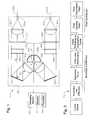
- FIGURE 1illustrates an example of a system 10 for which an endoilluminator output may be calculated.
- System 10may be located in an optical envelope 20 of a console of an endoilluminator system.
- the endoilluminator systemmay have an endoilluminator probe that projects light to illuminate a target, such as a region of a human or other organism.
- an endoilluminator probemay be a surgical instrument that projects illuminating light into an interior of an eyeball.
- system 10includes a lamp (or illuminator) 24, spherical mirrors 26 (26a-b), lenses 30 (30a-b), cold mirrors 32 (32a-b), hot mirrors 36 (36a-b), filters 40 (40a-b), attenuators 44 (44a-b), lenses 46 (46a-b), ports (50a-b), optical fibers (52a-b), and computing system 60 (which includes one or more memories 62 and one or more processors 64) optically, electrically, and/or mechanically coupled as illustrated.
- lamp 24provides light, which is directed towards lenses 30 and/or reflected by spherical mirrors 26 towards lenses 30.
- Lenses 30collimate and direct light towards cold mirrors 32, which transmit infrared light and reflect visible light towards hot mirrors 36.
- Hot mirrors 36pass through the visible light towards filters 40, which filter for the remaining ultraviolet and infrared light.
- Attenuators 44attenuate the light directed towards lenses 46, which focus the light towards ports 50. Ports couple the light to optical fibers 52.
- lamp 24may be any suitable light source, for example, an arc-lamp, light emitting diode (LED), or laser light source. Different types of lamps 24 may be used with system 10. For example, a particular type of lamp may be used and then replaced with another type of lamp.
- a mirror 26may be any suitable optical device (such as a reflective surface) that directs (such as reflects) light towards lens 30.
- mirror 26may be a spherical mirror.
- a lens 30may be any suitable optical device that collimates light.
- lens 30may be an aspheric condensing lens.
- a cold mirror 32may be any suitable optical device (such as a reflective surface) that directs (such as reflects) light towards hot mirror 36.
- cold mirror 32may be a dielectric mirror, or a dichroic filter, that reflects visible light while transmitting infrared light.
- a hot mirror 36may be any suitable optical device (such as an optical filter) that directs (such as transmits) light towards hot mirror filter 40.
- hot mirror 36may be a dielectric mirror, or a dichroic filter, that transmits visible light while reflecting infrared light.
- An auxiliary filtermay be used to change the color of the illumination light.
- An attenuator 44(44a-b) may be any suitable device that attenuates light, such as a louver attenuator.
- a lens 46may be any suitable optical device that directs light towards ports 50, such as an aspheric condensing lens that converts collimated light to directed light.
- a port 50couples light to an optical fiber 52.
- An optical fiber 52may be an optical waveguide that transmits light.
- Optical fiber 52may have any suitable diameter, for example, a diameter in the range of 0.1 millimeters (mm) to 1 mm. In certain embodiments, optical fiber 52 delivers the light to a probe, such as an endoilluminator probe.
- computing system 60 located in the console of an endoilluminator systemmay be used to control system 10.
- a usermay enter a set point for the output of an endoilluminator system into computing system 60 using, e.g., a graphical user interface (GUI) such as a touch screen.
- GUIgraphical user interface
- Computing system 60may control components of system 10 in order to maintain the set point.
- computing system 60may calculate the endoilluminator output, determine the difference between the output and the set point, and then adjust the components to compensate for the difference.
- computing system 60may adjust attenuator 44 and/or light source power to output more or less light.
- computing system 60may output (e.g., display) the endoilluminator output to the user.
- computing system 60may calculate the endoilluminator output using any suitable information, such as calibration and/or empirically determined (such as measured and/or recorded) information.
- the informationmay include, e.g., lamp or probe information, such as UFR and FTF information (described below).
- the informationmay be collected in any suitable manner, such as using wireless or wired communication, a stored lookup table, user input, a monitoring device that monitors one or more components of system 10, and/or other suitable process or device. For example, a read/write function can track lamp hours.
- FIGURE 2illustrates a diagram 70 showing an example of a method for calculating an endoilluminator output.
- the endoilluminator outputdescribes the output at a port 50 of an endoilluminator system.
- the outputmay be the luminous flux output.
- the endoilluminator outputmay be calculated from a mathematical function of the illuminator contribution of lamp 24 of the endoilluminator system and the fiber contribution of one or more optical fibers 52 of the endoilluminator system.
- the endoilluminator outputmay be the product of the illuminator contribution and the fiber contribution.
- the illuminator contributiondescribes the luminous flux output of the illuminator.
- the illuminator contributionmay be a mathematical function of one or more constants that describe lamp 24 and/or one or more time-dependent factors that take into account the age of lamp 24.
- the constant valuesmay include an illuminator leg efficiency, attenuation factor, and/or initial lamp performance.
- the time-dependent factorsmay include a lamp performance degradation factor.
- the illuminator contributionmay be directly sampled and measured.
- the fiber contributiondescribes how well optical fibers 52 transmit light.
- the fiber contributionmay be a function of constant values and/or time-dependent factors.
- a constant valuemay be a fiber coupling factor
- a time-dependent factormay be a fiber transmission ratio.
- ⁇ L⁇ L ⁇ f L ⁇ I P 0 ⁇ LIDF t ⁇ U ⁇ F ⁇ R ⁇ F ⁇ T ⁇ F t
- the illuminator contributionis given by ⁇ L ⁇ f L ⁇ I ( P 0 ) ⁇ LIDF (t), where ⁇ L is the illuminator leg efficiency, f L is the attenuator factor, I(P 0 ) is the initial lamp performance, and LIDF(t) is the lamp performance degradation factor.
- the fiber contributionis given by UFR ⁇ FTF ( t ), where UFR is the fiber transmission ratio of a fiber probe relative to a glass fiber standard (typically measured with a low intensity, stable, diffuse test source) and FTF(t) is the fiber transfer function (which is the coupling ratio of the actual source relative to the test source).
- the illuminator leg efficiencymeasures the percentage of optical efficiency of lamp 24 with respect to a reference lamp, which may be regarded as having the best efficiency. In certain embodiments, the illuminator leg efficiency may be determined during calibration performed during manufacture of lamp 24.
- the attenuator factordescribes the transmission through an attenuator 44 with respect to position of attenuator 44.
- the attenuator factormay be determined during manufacture of lamp 24. An example of an attenuator factor is described with reference to FIGURE 3 .
- the initial lamp performancedescribes the initial luminous flux output of lamp 24 through a standard fiber (such as a glass fiber standard that typically does not degrade over the duration of a test).
- the initial lamp performancemay be estimated using the power consumption of lamp 24 (measured, e.g., subsequent to the initial warm-up cycle of lamp 24) and a lamp intensity function that describes luminous flux output with respect to power consumption.
- the lamp intensity functionmay be determined in any suitable manner, e.g., from empirical data.
- An example of a lamp intensity functionis described with reference to FIGURE 4 .
- the initial lamp performancemay be determined in other suitable manners, e.g., by sampling the initial output of lamp 24.
- the initial lamp performancemay be adjusted in response to additional data, for example, additional power consumption data.
- a next initial lamp performancemay be determined for a next lamp, such as a replacement lamp.
- the next illuminator contribution of the next lampmay be calculated using the next initial lamp performance, and a next endoilluminator output of the endoilluminator system may be determined from the next illuminator contribution and the fiber contribution.
- the lamp performance degradation factordescribes the degradation of the intensity of lamp 24 as lamp 24 ages.
- the lamp performance degradation factormay be determined using a lamp intensity degradation function that is a normalized function of lamp age.
- the lamp performance degradation functionmay be determined from empirical data. For example, the data may describe how luminous flux measured through a standard fiber degrades as a function of the lamp age.
- the standard fibermay be, for example, a glass fiber standard (GFS), and may provide an angular and spatial aperture for the light to pass through in a controlled manner.
- An example of a lamp intensity degradation functionis described with reference to FIGURE 5 .
- the lamp performance degradationmay be determined in other suitable manners, e.g., by monitoring lamp power consumption. An example of determining lamp performance using measured power is described with reference to FIGURE 6 .
- the fiber coupling factordescribes how the luminous flux degrades as light is directed towards optical fiber 52.
- the fiber coupling factormay be determined from a fiber transfer function that describes how the luminous flux output of a specific type of probe degrades relative to the luminous flux output through a standard fiber.
- a particular probe typemay have a specific fiber transfer function.
- the fiber transfer functionmay be determined from empirical data and stored at computing system 60 or the probe.
- the fiber transmission ratiodescribes the ratio between the transmission of a particular probe and the transmission of a reference fiber.
- the fiber transmission ratiomay be the universal flux ratio (UFR).
- a code for the fiber transmission ratiomay be placed on the probe such that when the probe is connected to system 10, system 10 reads the code to obtain the fiber transmission ratio.
- the codemay be, e.g., a radio frequency identifier (RFID).
- FIGURE 3illustrates an example of an attenuator factor.
- Diagram 76shows an example of attenuator transmission with respect to attenuator position for a port 50. Attenuator transmission is given in percentage of transmission, and attenuator position is given in units of degrees or stepper motor steps, where a single stepper motion step produces a motion of a predetermined number of degrees per step (e.g., 0.5 degrees/ step).
- FIGURE 4illustrates an example of a lamp intensity function.
- Diagram 78shows an example of a lamp intensity function determined from data describing measured power consumption (given in watts) and luminous flux (given in lumens). A function may be calculated from data using any suitable curve-fitting technique.
- FIGURE 5illustrates an example of a lamp intensity degradation function.
- Diagram 78shows an example of a lamp output with respect to lamp age (given in hours). The lamp output is normalized with respect to the maximum output of the lamp.
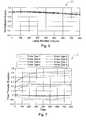
- FIGURE 6illustrates an example of determining lamp performance using measured power.
- Diagram 82shows measured power with respect to lamp age for different lamps, where H is an index that represents the degradation rate characteristic of a particular type of lamp.
- Diagram 84shows lamp performance with respect to lamp age for different lamps, which is determined from diagram 82.
- the rate of power increaseis proportional to the physical size of the emitting spot on the arc lamp.
- the optical systemreimages the emitting spot on the lamp to the entrance aperture of the fiber optic, so the coupling efficiency degrades inversely to the size of the lamp spot.
- monitoring the rate of power consumption increase over lamp burn lifeenables the system to select the appropriate lamp performance degradation factor curve (shown in 84).
- the index selectionis made prior to when the lamp performance degradation factor curves diverge substantially (e.g., at 50 hours).
- FIGURE 7illustrates examples of fiber transfer functions for different types of probes.
- Diagram 86shows fiber transfer functions with respect to time (given in runtime hours of the lamp).
- a component of the systems and apparatuses disclosed hereinmay include an interface, logic, memory, and/or other suitable element, any of which may include hardware and/or software.
- An interfacecan receive input, send output, process the input and/or output, and/or perform other suitable operations.
- Logiccan perform the operations of a component, for example, execute instructions to generate output from input.
- Logicmay be encoded in memory and may perform operations when executed by a computer.
- Logicmay be a processor, such as one or more computers, one or more microprocessors, one or more applications, and/or other logic.
- a memorycan store information and may comprise one or more tangible, computer-readable, and/or computer-executable storage medium.
- RAMRandom Access Memory
- ROMRead Only Memory
- mass storage mediafor example, a hard disk
- removable storage mediafor example, a Compact Disk (CD) or a Digital Video Disk (DVD)
- database and/or network storagefor example, a server
- network storagefor example, a server
- operations of the embodimentsmay be performed by one or more computer readable media encoded with a computer program, software, computer executable instructions, and/or instructions capable of being executed by a computer.
- the operationsmay be performed by one or more computer readable media storing, embodied with, and/or encoded with a computer program and/or having a stored and/or an encoded computer program.
- the inventionalso comprises methods according to the following numbered paragraphs 21-26:
Landscapes
- Health & Medical Sciences (AREA)
- Life Sciences & Earth Sciences (AREA)
- Surgery (AREA)
- General Health & Medical Sciences (AREA)
- Public Health (AREA)
- Veterinary Medicine (AREA)
- Animal Behavior & Ethology (AREA)
- Molecular Biology (AREA)
- Medical Informatics (AREA)
- Engineering & Computer Science (AREA)
- Biomedical Technology (AREA)
- Heart & Thoracic Surgery (AREA)
- Biophysics (AREA)
- Pathology (AREA)
- Physics & Mathematics (AREA)
- Nuclear Medicine, Radiotherapy & Molecular Imaging (AREA)
- Radiology & Medical Imaging (AREA)
- Optics & Photonics (AREA)
- Oral & Maxillofacial Surgery (AREA)
- Ophthalmology & Optometry (AREA)
- Circuit Arrangement For Electric Light Sources In General (AREA)
- Non-Portable Lighting Devices Or Systems Thereof (AREA)
Description
- The present disclosure relates generally to endoilluminators, and more particularly to providing consistent output from an endoilluminator system.
- An endoilluminator system has an endoilluminator probe that projects light to illuminate a target, such as an interior region of a part of a human (e.g., an eyeball) or other organism. For example, an endoillumination system may include an illumination console in addition to the endoilluminator probe. The illumination console houses a light source and optics that focus light from the source onto a connector port. The endoilluminator probe has a proximal end that connects to the illumination console at the port and a distal end that projects illuminating light. The output of the endoilluminator system describes the output at the distal end of the endoilluminator probe. Information regarding the endoilluminator output can be important to the user. For example, in vitreoretinal surgery, the amount of light is controlled to avoid excessive exposure to the retina. Certain known endoilluminator systems, however, fail to provide a technique for calculating the endoilluminator output that is accurate and efficient in certain situations.
- The present state of the art is represented by
US 2009/254287 A1 ,US 2006/069314 A1 ,US 2007/139924 A1 . - The present invention provides methods and systems for determining an endoilluminator output, in accordance with claims which follow.
- In certain embodiments, determining an endoilluminator output includes calculating an illuminator contribution of an endoilluminator system and a fiber contribution of one or more optical fibers of the endoilluminator system. The endoilluminator output is determined from the illuminator contribution and the fiber contribution. The illuminator contribution may be established using calibrated or empirically determined factors, such as an illuminator leg efficiency, an attenuator factor, an initial lamp performance, and/or a lamp performance degradation factor of the lamp. The fiber contribution may be established using calibrated or empirically determined factors, such as a fiber coupling factor and/or fiber transmission ratio of the optical fibers.
- Exemplary embodiments of the present disclosure will now be described by way of example in greater detail with reference to the attached figures, in which:
FIGURE 1 illustrates an example of a system for which output may be calculated according to certain embodiments;FIGURE 2 illustrates an example of a method for calculating an endoilluminator output according to certain embodiments;FIGURE 3 illustrates an example of an attenuator factor according to certain embodiments;FIGURE 4 illustrates an example of a lamp intensity function according to certain embodiments;FIGURE 5 illustrates an example of a lamp intensity degradation function according to certain embodiments;FIGURE 6 illustrates an example of determining lamp performance using measured power; andFIGURE 7 illustrates examples of fiber transfer functions for different types of probes according to certain embodiments.- Referring now to the description and drawings, example embodiments of the disclosed apparatuses, systems, and methods are shown in detail. The description and drawings are not intended to be exhaustive or otherwise limit or restrict the claims to the specific embodiments shown in the drawings and disclosed in the description. Although the drawings represent possible embodiments, the drawings are not necessarily to scale and certain features may be exaggerated, removed, or partially sectioned to better illustrate the embodiments.
FIGURE 1 illustrates an example of asystem 10 for which an endoilluminator output may be calculated.System 10 may be located in anoptical envelope 20 of a console of an endoilluminator system. The endoilluminator system may have an endoilluminator probe that projects light to illuminate a target, such as a region of a human or other organism. For example, an endoilluminator probe may be a surgical instrument that projects illuminating light into an interior of an eyeball.- In the illustrated example,
system 10 includes a lamp (or illuminator) 24, spherical mirrors 26 (26a-b), lenses 30 (30a-b), cold mirrors 32 (32a-b), hot mirrors 36 (36a-b), filters 40 (40a-b), attenuators 44 (44a-b), lenses 46 (46a-b), ports (50a-b), optical fibers (52a-b), and computing system 60 (which includes one ormore memories 62 and one or more processors 64) optically, electrically, and/or mechanically coupled as illustrated. In an example of operation,lamp 24 provides light, which is directed towards lenses 30 and/or reflected by spherical mirrors 26 towards lenses 30. Lenses 30 collimate and direct light towards cold mirrors 32, which transmit infrared light and reflect visible light towards hot mirrors 36. Hot mirrors 36 pass through the visible light towards filters 40, which filter for the remaining ultraviolet and infrared light. Attenuators 44 attenuate the light directed towards lenses 46, which focus the light towardsports 50. Ports couple the light to optical fibers 52. - In particular embodiments,
lamp 24 may be any suitable light source, for example, an arc-lamp, light emitting diode (LED), or laser light source. Different types oflamps 24 may be used withsystem 10. For example, a particular type of lamp may be used and then replaced with another type of lamp. A mirror 26 may be any suitable optical device (such as a reflective surface) that directs (such as reflects) light towards lens 30. For example, mirror 26 may be a spherical mirror. A lens 30 may be any suitable optical device that collimates light. For example, lens 30 may be an aspheric condensing lens. - A cold mirror 32 may be any suitable optical device (such as a reflective surface) that directs (such as reflects) light towards hot mirror 36. For example, cold mirror 32 may be a dielectric mirror, or a dichroic filter, that reflects visible light while transmitting infrared light. A hot mirror 36 may be any suitable optical device (such as an optical filter) that directs (such as transmits) light towards hot mirror filter 40. For example, hot mirror 36 may be a dielectric mirror, or a dichroic filter, that transmits visible light while reflecting infrared light.
- An auxiliary filter may be used to change the color of the illumination light. An attenuator 44 (44a-b) may be any suitable device that attenuates light, such as a louver attenuator. A lens 46 may be any suitable optical device that directs light towards
ports 50, such as an aspheric condensing lens that converts collimated light to directed light. Aport 50 couples light to an optical fiber 52. An optical fiber 52 may be an optical waveguide that transmits light. Optical fiber 52 may have any suitable diameter, for example, a diameter in the range of 0.1 millimeters (mm) to 1 mm. In certain embodiments, optical fiber 52 delivers the light to a probe, such as an endoilluminator probe. - In certain embodiments,
computing system 60 located in the console of an endoilluminator system may be used to controlsystem 10. For example, a user may enter a set point for the output of an endoilluminator system intocomputing system 60 using, e.g., a graphical user interface (GUI) such as a touch screen.Computing system 60 may control components ofsystem 10 in order to maintain the set point. For example,computing system 60 may calculate the endoilluminator output, determine the difference between the output and the set point, and then adjust the components to compensate for the difference. In certain embodiments,computing system 60 may adjust attenuator 44 and/or light source power to output more or less light. In certain embodiments,computing system 60 may output (e.g., display) the endoilluminator output to the user. - In certain embodiments,
computing system 60 may calculate the endoilluminator output using any suitable information, such as calibration and/or empirically determined (such as measured and/or recorded) information. The information may include, e.g., lamp or probe information, such as UFR and FTF information (described below). The information may be collected in any suitable manner, such as using wireless or wired communication, a stored lookup table, user input, a monitoring device that monitors one or more components ofsystem 10, and/or other suitable process or device. For example, a read/write function can track lamp hours. FIGURE 2 illustrates a diagram 70 showing an example of a method for calculating an endoilluminator output. The endoilluminator output describes the output at aport 50 of an endoilluminator system. The output may be the luminous flux output. In certain embodiments, the endoilluminator output may be calculated from a mathematical function of the illuminator contribution oflamp 24 of the endoilluminator system and the fiber contribution of one or more optical fibers 52 of the endoilluminator system.- In certain embodiments, the endoilluminator output may be the product of the illuminator contribution and the fiber contribution. For example the endoilluminator output ΦL may be described using Equation (1):

- The illuminator contribution describes the luminous flux output of the illuminator. In certain embodiments, the illuminator contribution may be a mathematical function of one or more constants that describe
lamp 24 and/or one or more time-dependent factors that take into account the age oflamp 24. For example, the constant values may include an illuminator leg efficiency, attenuation factor, and/or initial lamp performance. The time-dependent factors may include a lamp performance degradation factor. In certain embodiments, the illuminator contribution may be directly sampled and measured. - The fiber contribution describes how well optical fibers 52 transmit light. In certain embodiments, the fiber contribution may be a function of constant values and/or time-dependent factors. For example, a constant value may be a fiber coupling factor, and a time-dependent factor may be a fiber transmission ratio.
- In certain embodiments, the illuminator contribution and the fiber contribution may be described using Equation (2):

- The illuminator contribution is given byηL ×fL ×I(P0) ×LIDF(t), whereηL is the illuminator leg efficiency,fL is the attenuator factor,I(P0) is the initial lamp performance, andLIDF(t) is the lamp performance degradation factor. The fiber contribution is given byUFR ×FTF(t), where UFR is the fiber transmission ratio of a fiber probe relative to a glass fiber standard (typically measured with a low intensity, stable, diffuse test source) andFTF(t) is the fiber transfer function (which is the coupling ratio of the actual source relative to the test source).
- The illuminator leg efficiency measures the percentage of optical efficiency of
lamp 24 with respect to a reference lamp, which may be regarded as having the best efficiency. In certain embodiments, the illuminator leg efficiency may be determined during calibration performed during manufacture oflamp 24. - The attenuator factor describes the transmission through an attenuator 44 with respect to position of attenuator 44. In certain embodiments, the attenuator factor may be determined during manufacture of
lamp 24. An example of an attenuator factor is described with reference toFIGURE 3 . - The initial lamp performance describes the initial luminous flux output of
lamp 24 through a standard fiber (such as a glass fiber standard that typically does not degrade over the duration of a test). In certain embodiments, the initial lamp performance may be estimated using the power consumption of lamp 24 (measured, e.g., subsequent to the initial warm-up cycle of lamp 24) and a lamp intensity function that describes luminous flux output with respect to power consumption. The lamp intensity function may be determined in any suitable manner, e.g., from empirical data. An example of a lamp intensity function may be described using Equation (3):
whereCi are determined empirically, and n > 0, such as n > 3, e.g., n = 9. An example of a lamp intensity function is described with reference toFIGURE 4 . - The initial lamp performance may be determined in other suitable manners, e.g., by sampling the initial output of
lamp 24. In certain embodiments, the initial lamp performance may be adjusted in response to additional data, for example, additional power consumption data. In certain embodiments, a next initial lamp performance may be determined for a next lamp, such as a replacement lamp. The next illuminator contribution of the next lamp may be calculated using the next initial lamp performance, and a next endoilluminator output of the endoilluminator system may be determined from the next illuminator contribution and the fiber contribution. - The lamp performance degradation factor describes the degradation of the intensity of
lamp 24 aslamp 24 ages. In certain embodiments, the lamp performance degradation factor may be determined using a lamp intensity degradation function that is a normalized function of lamp age. The lamp performance degradation function may be determined from empirical data. For example, the data may describe how luminous flux measured through a standard fiber degrades as a function of the lamp age. The standard fiber may be, for example, a glass fiber standard (GFS), and may provide an angular and spatial aperture for the light to pass through in a controlled manner. An example of a lamp performance degradation function may be described using Equation (4):
whereAi are determined empirically, and n > 0, such as n > 3, e.g., n = 9. An example of a lamp intensity degradation function is described with reference toFIGURE 5 . - The lamp performance degradation may be determined in other suitable manners, e.g., by monitoring lamp power consumption. An example of determining lamp performance using measured power is described with reference to
FIGURE 6 . - The fiber coupling factor describes how the luminous flux degrades as light is directed towards optical fiber 52. The fiber coupling factor may be determined from a fiber transfer function that describes how the luminous flux output of a specific type of probe degrades relative to the luminous flux output through a standard fiber. In certain embodiments, a particular probe type may have a specific fiber transfer function. The fiber transfer function may be determined from empirical data and stored at
computing system 60 or the probe. An example of a fiber transfer function may be described using Equation (5):
whereBl are determined empirically, and n > 0, such as n > 3, e.g., n = 9. Examples of fiber transfer functions for different types of probes are described in more detail with reference toFIGURE 6 . - The fiber transmission ratio describes the ratio between the transmission of a particular probe and the transmission of a reference fiber. For example, the fiber transmission ratio may be the universal flux ratio (UFR). In certain embodiments, a code for the fiber transmission ratio may be placed on the probe such that when the probe is connected to
system 10,system 10 reads the code to obtain the fiber transmission ratio. The code may be, e.g., a radio frequency identifier (RFID). FIGURE 3 illustrates an example of an attenuator factor. Diagram 76 shows an example of attenuator transmission with respect to attenuator position for aport 50. Attenuator transmission is given in percentage of transmission, and attenuator position is given in units of degrees or stepper motor steps, where a single stepper motion step produces a motion of a predetermined number of degrees per step (e.g., 0.5 degrees/ step).FIGURE 4 illustrates an example of a lamp intensity function. Diagram 78 shows an example of a lamp intensity function determined from data describing measured power consumption (given in watts) and luminous flux (given in lumens). A function may be calculated from data using any suitable curve-fitting technique.FIGURE 5 illustrates an example of a lamp intensity degradation function. Diagram 78 shows an example of a lamp output with respect to lamp age (given in hours). The lamp output is normalized with respect to the maximum output of the lamp.FIGURE 6 illustrates an example of determining lamp performance using measured power. Diagram 82 shows measured power with respect to lamp age for different lamps, where H is an index that represents the degradation rate characteristic of a particular type of lamp. Diagram 84 shows lamp performance with respect to lamp age for different lamps, which is determined from diagram 82.- For arc lamps, the rate of power increase is proportional to the physical size of the emitting spot on the arc lamp. The optical system reimages the emitting spot on the lamp to the entrance aperture of the fiber optic, so the coupling efficiency degrades inversely to the size of the lamp spot. Hence, for lamps that exhibit significant manufacturing variation, monitoring the rate of power consumption increase over lamp burn life enables the system to select the appropriate lamp performance degradation factor curve (shown in 84). In certain embodiments, the index selection is made prior to when the lamp performance degradation factor curves diverge substantially (e.g., at 50 hours).
FIGURE 7 illustrates examples of fiber transfer functions for different types of probes. Diagram 86 shows fiber transfer functions with respect to time (given in runtime hours of the lamp). A fiber transfer function (FTF) may be expressed as the ratio of luminous flux for the probe to that of a glass fiber standard (GFS), divided by the probe UFR, that is, FTF = luminous flux from probe / (luminous flux from GFS *UFR of probe).- A component of the systems and apparatuses disclosed herein may include an interface, logic, memory, and/or other suitable element, any of which may include hardware and/or software. An interface can receive input, send output, process the input and/or output, and/or perform other suitable operations. Logic can perform the operations of a component, for example, execute instructions to generate output from input. Logic may be encoded in memory and may perform operations when executed by a computer. Logic may be a processor, such as one or more computers, one or more microprocessors, one or more applications, and/or other logic. A memory can store information and may comprise one or more tangible, computer-readable, and/or computer-executable storage medium. Examples of memory include computer memory (for example, Random Access Memory (RAM) or Read Only Memory (ROM)), mass storage media (for example, a hard disk), removable storage media (for example, a Compact Disk (CD) or a Digital Video Disk (DVD)), database and/or network storage (for example, a server), and/or other computer-readable media.
- In particular embodiments, operations of the embodiments may be performed by one or more computer readable media encoded with a computer program, software, computer executable instructions, and/or instructions capable of being executed by a computer. In particular embodiments, the operations may be performed by one or more computer readable media storing, embodied with, and/or encoded with a computer program and/or having a stored and/or an encoded computer program.
- Although this disclosure has been described in terms of certain embodiments, modifications (such as changes, substitutions, additions, omissions, and/or other modifications) of the embodiments will be apparent to those skilled in the art. Accordingly, modifications may be made to the embodiments without departing from the scope of the invention. For example, modifications may be made to the systems and apparatuses disclosed herein. The components of the systems and apparatuses may be integrated or separated, and the operations of the systems and apparatuses may be performed by more, fewer, or other components. As another example, modifications may be made to the methods disclosed herein. The methods may include more, fewer, or other steps, and the steps may be performed in any suitable order.
- Other modifications are possible without departing from the scope of the invention. For example, the description illustrates embodiments in particular practical applications, yet other applications will be apparent to those skilled in the art. In addition, future developments will occur in the arts discussed herein, and the disclosed systems, apparatuses, and methods will be utilized with such future developments.
- The scope of the invention should not be determined with reference to the description. In accordance with patent statutes, the description explains and illustrates the principles and modes of operation of the invention using exemplary embodiments. The description enables others skilled in the art to utilize the systems, apparatuses, and methods in various embodiments and with various modifications, but should not be used to determine the scope of the invention.
- The scope of the invention should be determined with reference to the claims and the full scope of equivalents to which the claims are entitled. All claims terms should be given their broadest reasonable constructions and their ordinary meanings as understood by those skilled in the art, unless an explicit indication to the contrary is made herein. For example, use of the singular articles such as "a," "the," etc. should be read to recite one or more of the indicated elements, unless a claim recites an explicit limitation to the contrary. As another example, "each" refers to each member of a set or each member of a subset of a set, where a set may include zero, one, or more than one element. In sum, the invention is capable of modification, and the scope of the invention should be determined, not with reference to the description, but with reference to the claims and their full scope of equivalents.
- The invention also comprises methods according to the following numbered paragraphs 21-26:
- 21. A method for determining an endoilluminator output comprising:
- establishing an initial lamp performance;
- calculating an illuminator contribution using the initial lamp performance;
- calculating a fiber contribution; and
- determining the endoilluminator output from the illuminator contribution and the fiber contribution.
- 22. The method of paragraph 21, further comprising:
- receiving a set point for the endoilluminator system; and
- adjusting one or more components of the endoilluminator system to match the endoilluminator output to the set point.
- 23. The method of paragraph, further comprising:
- monitoring lamp degradation of the lamp; and
- adjusting one or more components of the endoilluminator system to compensate for the lamp degradation.
- 24. A method for determining an endoilluminator output comprising:
- establishing a fiber coupling factor;
- calculating a fiber contribution using the fiber coupling factor;
- calculating an illuminator contribution; and
- determining the endoilluminator output from the fiber contribution and the illuminator contribution.
- 25. The method of
paragraph 24, further comprising:- receiving a set point for the endoilluminator system; and
- adjusting one or more components of the endoilluminator system to match the endoilluminator output to the set point.
- 26. The method of
paragraph 24, further comprising:- monitoring lamp degradation of the lamp; and
- adjusting one or more components of the endoilluminator system to compensate for the lamp degradation.


Claims (20)
- A method for determining an endoilluminator output comprising:establishing a lamp performance degradation factor of a lamp (24) of an endoilluminator system;calculating an illuminator contribution as defined by the luminous flux output of the illuminator of the lamp and using the lamp performance degradation factor;characterised in that the method further comprises the steps of calculating a fiber contribution of one or more optical fibers (52) of the endoilluminator system as a function of constant values and/or time-dependent values describing how well the optical fibers transmit light; anddetermining the endoilluminator output of the endoilluminator system from the illuminator contribution and the fiber contribution.
- The method of Claim 1, further comprising:receiving a set point for the endoilluminator system; andadjusting one or more components of the endoilluminator system to match the endoilluminator output to the set point.
- The method of Claim 1, further comprising:monitoring lamp degradation of the lamp (24); andadjusting one or more components of the endoilluminator system to compensate for the lamp degradation.
- The method of Claim 1, the calculating the illuminator contribution further comprising:establishing an illuminator leg efficiency of the lamp (24); andcalculating the illuminator contribution using the illuminator leg efficiency.
- The method of Claim 1, the calculating the illuminator contribution further comprising:establishing an attenuator (44) factor of the lamp (24); andcalculating the illuminator contribution using the attenuator factor.
- The method of Claim 1, the calculating the illuminator contribution further comprising:establishing an initial lamp performance of the lamp (24); andcalculating the illuminator contribution using the initial lamp performance.
- The method of Claim 1, the calculating the fiber contribution further comprising:establishing a fiber coupling factor of the one or more fibers as a constant value; andcalculating the fiber contribution using the fiber coupling factor.
- The method of Claim 1, the calculating the fiber contribution further comprising:establishing a fiber transmission ratio of the one or more fibers (52) as a time-dependent factor; andcalculating the fiber contribution using the fiber transmission ratio.
- The method of Claim 1, further comprising:determining a next initial lamp performance of a next lamp;calculating a next illuminator contribution of the next lamp using the next initial lamp performance; anddetermining a next endoilluminator output of the endoilluminator system from the next illuminator contribution and the fiber contribution.
- The method of Claim 1, further comprising:collecting information to determine the endoilluminator output using wireless or wired communication, a stored lookup table, user input, or a monitoring device.
- A system (10) for determining an endoilluminator output comprising:one or more memories (62) configured to store a lamp (24) performance degradation factor of a lamp of an endoilluminator system; andone or more processors (64) configured to:calculate an illuminator contribution as defined by the luminous flux output of the illuminator of the lamp and using the lamp performance degradation factor;characterised in that the one or more processors are further configured to calculate a fiber contribution of one or more optical fibers (52) of the endoilluminator system as a function of constant values and/or time-dependent values describing how well the optical fibers transmit light;determine the endoilluminator output of the endoilluminator system from the illuminator contribution and the fiber contribution.
- The system of Claim 11, the one or more processors (64) further configured to:receive a set point for the endoilluminator system; andadjust one or more components of the endoilluminator system to match the endoilluminator output to the set point.
- The system of Claim 11, the one or more processors (64) further configured to:monitor lamp degradation of the lamp (24); andadjust one or more components of the endoilluminator system to compensate for the lamp degradation.
- The system of Claim 11, the calculating the illuminator contribution further comprising:establishing an illuminator leg efficiency of the lamp (24); andcalculating the illuminator contribution using the illuminator leg efficiency.
- The system of Claim 11, the calculating the illuminator contribution further comprising:establishing an attenuator (44) factor of the lamp (24); andcalculating the illuminator contribution using the attenuator factor.
- The system of Claim 11, the calculating the illuminator contribution further comprising:establishing an initial lamp performance of the lamp (24); andcalculating the illuminator contribution using the initial lamp performance.
- The system of Claim 11, the calculating the fiber contribution further comprising:establishing a fiber coupling factor of the one or more fibers (52); andcalculating the fiber contribution using the fiber coupling factor.
- The system of Claim 11, the calculating the fiber contribution further comprising:establishing a fiber transmission ratio of the one or more fibers (52); andcalculating the fiber contribution using the fiber transmission ratio.
- The system of Claim 11, the one or more processors further configured to:determine a next initial lamp performance of a next lamp;calculate a next illuminator contribution of the next lamp using the next initial lamp performance; anddetermine a next endoilluminator output of the endoilluminator system from the next illuminator contribution and the fiber contribution.
- The system of Claim 11, the one or more processors further configured to:collect information to determine the endoilluminator output using wireless or wired communication, a stored lookup table, user input, or a monitoring device.
Applications Claiming Priority (2)
| Application Number | Priority Date | Filing Date | Title |
|---|---|---|---|
| US13/334,333US8688401B2 (en) | 2011-12-22 | 2011-12-22 | Providing consistent output from an endoilluminator system |
| PCT/US2012/062917WO2013095776A1 (en) | 2011-12-22 | 2012-11-01 | Providing consistent output from an endoilluminator system |
Publications (3)
| Publication Number | Publication Date |
|---|---|
| EP2766660A1 EP2766660A1 (en) | 2014-08-20 |
| EP2766660A4 EP2766660A4 (en) | 2014-12-10 |
| EP2766660B1true EP2766660B1 (en) | 2016-01-13 |
Family
ID=48654363
Family Applications (1)
| Application Number | Title | Priority Date | Filing Date |
|---|---|---|---|
| EP12860036.8AActiveEP2766660B1 (en) | 2011-12-22 | 2012-11-01 | Providing consistent output from an endoilluminator system |
Country Status (8)
| Country | Link |
|---|---|
| US (1) | US8688401B2 (en) |
| EP (1) | EP2766660B1 (en) |
| JP (1) | JP6174598B2 (en) |
| CN (1) | CN103958965B (en) |
| AU (1) | AU2012355881B2 (en) |
| CA (1) | CA2854541C (en) |
| ES (1) | ES2567592T3 (en) |
| WO (1) | WO2013095776A1 (en) |
Families Citing this family (6)
| Publication number | Priority date | Publication date | Assignee | Title |
|---|---|---|---|---|
| US9970818B2 (en) | 2013-11-01 | 2018-05-15 | Tokyo Electron Limited | Spatially resolved optical emission spectroscopy (OES) in plasma processing |
| US10473525B2 (en) | 2013-11-01 | 2019-11-12 | Tokyo Electron Limited | Spatially resolved optical emission spectroscopy (OES) in plasma processing |
| US10215704B2 (en) | 2017-03-02 | 2019-02-26 | Tokyo Electron Limited | Computed tomography using intersecting views of plasma using optical emission spectroscopy during plasma processing |
| WO2020092889A1 (en) | 2018-11-01 | 2020-05-07 | Medical Instrument Development Laboratories, Inc. | Led illumination system |
| EP4266975A1 (en) | 2020-12-22 | 2023-11-01 | Alcon Inc. | Light exposure quantification strategy for preventing light toxicity during an ophthalmic procedure |
| WO2023002268A1 (en) | 2021-07-20 | 2023-01-26 | Alcon Inc. | Light engine calibration systems and methods |
Family Cites Families (60)
| Publication number | Priority date | Publication date | Assignee | Title |
|---|---|---|---|---|
| US3327712A (en) | 1961-09-15 | 1967-06-27 | Ira H Kaufman | Photocoagulation type fiber optical surgical device |
| US3703176A (en) | 1970-05-28 | 1972-11-21 | Arthur Vassiliadis | Slit lamp photocoagulator |
| US3930504A (en) | 1973-12-12 | 1976-01-06 | Clinitex, Inc. | Portable light coagulator |
| IL49999A (en) | 1976-01-07 | 1979-12-30 | Mochida Pharm Co Ltd | Laser apparatus for operations |
| US4068956A (en) | 1976-04-16 | 1978-01-17 | John Taboada | Pulsed laser densitometer system |
| US4165180A (en) | 1977-06-17 | 1979-08-21 | Canadian Instrumentation And Research Limited | Automatic computing color meter |
| DE2821883C2 (en) | 1978-05-19 | 1980-07-17 | Ibm Deutschland Gmbh, 7000 Stuttgart | Device for material processing |
| EP0048410B1 (en) | 1980-09-22 | 1985-03-27 | Olympus Optical Co., Ltd. | A laser device for an endoscope |
| US4542956A (en) | 1982-12-30 | 1985-09-24 | Newport Corporation | Fiber optics transfer systems |
| US4626999A (en) | 1984-04-18 | 1986-12-02 | Cincinnati Milacron Inc. | Apparatus for controlled manipulation of laser focus point |
| US4729621A (en) | 1985-03-11 | 1988-03-08 | Shiley Inc. | Integral optical fiber coupler |
| JP2592085B2 (en) | 1988-02-09 | 1997-03-19 | マツダ株式会社 | Anti-lock device |
| US4961622A (en) | 1988-02-25 | 1990-10-09 | University Of Houston - University Park | Optical coupler and refractive lamp |
| US5371347A (en) | 1991-10-15 | 1994-12-06 | Gap Technologies, Incorporated | Electro-optical scanning system with gyrating scan head |
| JP3165146B2 (en) | 1990-11-16 | 2001-05-14 | 株式会社ニデック | Laser therapy equipment |
| EP0536951B1 (en) | 1991-10-10 | 1997-08-27 | Coherent, Inc. | Apparatus for delivering a defocused laser beam having a sharp-edged cross-section |
| JP2917704B2 (en) | 1992-10-01 | 1999-07-12 | 日本電気株式会社 | Exposure equipment |
| US5405659A (en) | 1993-03-05 | 1995-04-11 | University Of Puerto Rico | Method and apparatus for removing material from a target by use of a ring-shaped elliptical laser beam and depositing the material onto a substrate |
| EP0687956B2 (en) | 1994-06-17 | 2005-11-23 | Carl Zeiss SMT AG | Illumination device |
| US5856721A (en) | 1994-09-08 | 1999-01-05 | Gordin; Myron K. | Discharge lamp with offset or tilted arc tube |
| US5947957A (en) | 1994-12-23 | 1999-09-07 | Jmar Technology Co. | Portable laser for blood sampling |
| JP3132991B2 (en) | 1995-09-18 | 2001-02-05 | ウエスト電気株式会社 | Variable illumination angle flash device |
| US5754719A (en) | 1996-11-22 | 1998-05-19 | Cogent Light Technologies, Inc. | Method for coupling light from single fiberoptic to a multi-fiber bundle with enhanced field uniformity and better coupling efficiency |
| US5933274A (en) | 1997-05-15 | 1999-08-03 | Andrew F. DeSimone | Dye laser system |
| US6154595A (en) | 1997-07-14 | 2000-11-28 | Matsushita Electric Works, Ltd. | Side-face illuminating optical fiber |
| JPH11329038A (en) | 1998-05-13 | 1999-11-30 | Olympus Optical Co Ltd | Light guide lighting system |
| JP3505107B2 (en) | 1999-07-09 | 2004-03-08 | ペンタックス株式会社 | Excitation light filter for fluorescent endoscope |
| EP1134572B1 (en) | 1999-09-06 | 2006-11-15 | Anritsu Corporation | System for measuring wavelength dispersion of optical fiber |
| JP4994556B2 (en) | 2000-03-17 | 2012-08-08 | ストラテジック パテント アクイジションズ エルエルシー | High clarity lens system |
| US7102700B1 (en) | 2000-09-02 | 2006-09-05 | Magic Lantern Llc | Laser projection system |
| CA2336497A1 (en) | 2000-12-20 | 2002-06-20 | Daniel Chevalier | Lighting device |
| US6628877B2 (en) | 2001-01-02 | 2003-09-30 | Clark-Mxr, Inc. | Index trimming of optical waveguide devices using ultrashort laser pulses for arbitrary control of signal amplitude, phase, and polarization |
| WO2003050581A1 (en) | 2001-12-06 | 2003-06-19 | Florida Institute Of Technology | Method and apparatus for spatial domain multiplexing in optical fiber communications |
| US7106456B1 (en) | 2002-01-09 | 2006-09-12 | Interphase Technologies, Inc. | Common-path point-diffraction phase-shifting interferometer |
| US7474339B2 (en) | 2002-12-18 | 2009-01-06 | Nikon Corporation | Image-processing device with a first image sensor and a second image sensor |
| JP4346926B2 (en) | 2003-02-27 | 2009-10-21 | キヤノン株式会社 | Strobe photographing system and imaging apparatus |
| SG137674A1 (en) | 2003-04-24 | 2007-12-28 | Semiconductor Energy Lab | Beam homogenizer, laser irradiation apparatus, and method for manufacturing semiconductor device |
| US20060268231A1 (en) | 2003-07-03 | 2006-11-30 | Medibell Medicall Vision Technologies, Ltd. | Illumination method and system for obtaining color images by transcleral ophthalmic illumination |
| EP2298214B1 (en) | 2003-07-28 | 2013-11-06 | Synergetics, Inc. | Illumination and laser source and method of transmitting illumination light and laser treatment light |
| ES2415509T3 (en) | 2003-07-28 | 2013-07-25 | Synergetics, Inc. | Lighting source |
| US7502178B2 (en) | 2003-08-29 | 2009-03-10 | International Technology Center | Multiple wavelength and multiple field of view imaging devices and methods |
| JP2005165292A (en) | 2003-11-28 | 2005-06-23 | Carl Zeiss Ag | Surgical microscope for ophthalmology and method for using the same |
| WO2005076083A1 (en) | 2004-02-07 | 2005-08-18 | Carl Zeiss Smt Ag | Illumination system for a microlithographic projection exposure apparatus |
| US20060033926A1 (en) | 2004-08-13 | 2006-02-16 | Artsyukhovich Alexander N | Spatially distributed spectrally neutral optical attenuator |
| US8480566B2 (en) | 2004-09-24 | 2013-07-09 | Vivid Medical, Inc. | Solid state illumination for endoscopy |
| US7292323B2 (en) | 2004-11-12 | 2007-11-06 | Alcon, Inc. | Optical fiber detection method and system |
| US7599591B2 (en) | 2006-01-12 | 2009-10-06 | Optimedica Corporation | Optical delivery systems and methods of providing adjustable beam diameter, spot size and/or spot shape |
| WO2007115034A2 (en) | 2006-03-31 | 2007-10-11 | Alcon, Inc. | Method and system for correcting an optical beam |
| JP2007289581A (en)* | 2006-04-27 | 2007-11-08 | Pentax Corp | Endoscope light source device |
| JP4864528B2 (en)* | 2006-04-27 | 2012-02-01 | Hoya株式会社 | Endoscope device |
| EP1913864A1 (en) | 2006-10-15 | 2008-04-23 | Medic.Nrg Ltd. | Illuminator for medical use |
| US7847764B2 (en) | 2007-03-15 | 2010-12-07 | Global Oled Technology Llc | LED device compensation method |
| US7682027B2 (en) | 2007-04-09 | 2010-03-23 | Alcon, Inc. | Multi-LED ophthalmic illuminator |
| JP2008310992A (en)* | 2007-06-12 | 2008-12-25 | Fujifilm Corp | Light irradiation device |
| US9402643B2 (en)* | 2008-01-15 | 2016-08-02 | Novartis Ag | Targeted illumination for surgical instrument |
| JP5056549B2 (en)* | 2008-04-04 | 2012-10-24 | 日亜化学工業株式会社 | Optical semiconductor element lifetime prediction method and optical semiconductor element driving apparatus |
| WO2011019505A1 (en)* | 2009-08-12 | 2011-02-17 | Alcon Research, Ltd. | White light emitting diode (led) illuminator for ophthalmic endoillumination |
| JP5698239B2 (en)* | 2009-08-21 | 2015-04-08 | アルコン リサーチ, リミテッド | Fixed optical system with adjustable target |
| US8480279B2 (en)* | 2009-11-11 | 2013-07-09 | Alcon Research, Ltd. | Structured illumination probe and method |
| CN102665531B (en)* | 2009-11-11 | 2014-11-12 | 爱尔康研究有限公司 | Structured illumination probe and method |
- 2011
- 2011-12-22USUS13/334,333patent/US8688401B2/enactiveActive
- 2012
- 2012-11-01AUAU2012355881Apatent/AU2012355881B2/ennot_activeCeased
- 2012-11-01ESES12860036.8Tpatent/ES2567592T3/enactiveActive
- 2012-11-01WOPCT/US2012/062917patent/WO2013095776A1/enactiveApplication Filing
- 2012-11-01CACA2854541Apatent/CA2854541C/ennot_activeExpired - Fee Related
- 2012-11-01CNCN201280059601.9Apatent/CN103958965B/ennot_activeExpired - Fee Related
- 2012-11-01EPEP12860036.8Apatent/EP2766660B1/enactiveActive
- 2012-11-01JPJP2014549048Apatent/JP6174598B2/enactiveActive
Also Published As
| Publication number | Publication date |
|---|---|
| AU2012355881A1 (en) | 2014-05-22 |
| US20130163276A1 (en) | 2013-06-27 |
| CN103958965A (en) | 2014-07-30 |
| JP2015506540A (en) | 2015-03-02 |
| JP6174598B2 (en) | 2017-08-02 |
| CA2854541A1 (en) | 2013-06-27 |
| US8688401B2 (en) | 2014-04-01 |
| EP2766660A1 (en) | 2014-08-20 |
| EP2766660A4 (en) | 2014-12-10 |
| AU2012355881B2 (en) | 2015-02-05 |
| CA2854541C (en) | 2019-03-19 |
| WO2013095776A1 (en) | 2013-06-27 |
| CN103958965B (en) | 2017-03-22 |
| ES2567592T3 (en) | 2016-04-25 |
Similar Documents
| Publication | Publication Date | Title |
|---|---|---|
| EP2766660B1 (en) | Providing consistent output from an endoilluminator system | |
| JP7556102B2 (en) | Multi-input coupling illuminated multi-spot laser probe | |
| EP1653896B1 (en) | Coaxial illuminated laser endoscopic probe | |
| AU2016362115B2 (en) | Optical fiber having proximal taper for ophthalmic surgical illumination | |
| AU2006308686B2 (en) | Surgical wide-angle illuminator | |
| US11172560B2 (en) | Ophthalmic illumination system with controlled chromaticity | |
| US20070139950A1 (en) | Coaxial illuminated laser endoscopic probe and active numerical aperture control | |
| JP6994574B2 (en) | Light source device for endoscopes, endoscopes, and endoscope systems | |
| JP2025501963A (en) | Fiber optic medical treatment device | |
| JP7091453B2 (en) | Optical connection module for endoscopes, endoscopes, and endoscope systems | |
| US9968416B2 (en) | Ophthalmic illumination systems, devices, and methods |
Legal Events
| Date | Code | Title | Description |
|---|---|---|---|
| PUAI | Public reference made under article 153(3) epc to a published international application that has entered the european phase | Free format text:ORIGINAL CODE: 0009012 | |
| 17P | Request for examination filed | Effective date:20140509 | |
| AK | Designated contracting states | Kind code of ref document:A1 Designated state(s):AL AT BE BG CH CY CZ DE DK EE ES FI FR GB GR HR HU IE IS IT LI LT LU LV MC MK MT NL NO PL PT RO RS SE SI SK SM TR | |
| A4 | Supplementary search report drawn up and despatched | Effective date:20141112 | |
| RIC1 | Information provided on ipc code assigned before grant | Ipc:A61B 19/00 20060101ALN20141106BHEP Ipc:A61B 1/07 20060101ALI20141106BHEP Ipc:A61B 1/00 20060101ALI20141106BHEP Ipc:A61B 1/06 20060101ALI20141106BHEP Ipc:F21V 33/00 20060101AFI20141106BHEP Ipc:A61B 3/00 20060101ALI20141106BHEP | |
| DAX | Request for extension of the european patent (deleted) | ||
| GRAP | Despatch of communication of intention to grant a patent | Free format text:ORIGINAL CODE: EPIDOSNIGR1 | |
| RIC1 | Information provided on ipc code assigned before grant | Ipc:A61B 3/00 20060101ALI20150611BHEP Ipc:A61B 1/07 20060101ALI20150611BHEP Ipc:F21V 33/00 20060101AFI20150611BHEP Ipc:A61B 19/00 20060101ALN20150611BHEP Ipc:A61B 1/00 20060101ALI20150611BHEP Ipc:A61B 1/06 20060101ALI20150611BHEP | |
| RAP1 | Party data changed (applicant data changed or rights of an application transferred) | Owner name:ALCON RESEARCH, LTD | |
| INTG | Intention to grant announced | Effective date:20150706 | |
| GRAS | Grant fee paid | Free format text:ORIGINAL CODE: EPIDOSNIGR3 | |
| GRAA | (expected) grant | Free format text:ORIGINAL CODE: 0009210 | |
| AK | Designated contracting states | Kind code of ref document:B1 Designated state(s):AL AT BE BG CH CY CZ DE DK EE ES FI FR GB GR HR HU IE IS IT LI LT LU LV MC MK MT NL NO PL PT RO RS SE SI SK SM TR | |
| REG | Reference to a national code | Ref country code:GB Ref legal event code:FG4D | |
| REG | Reference to a national code | Ref country code:CH Ref legal event code:EP | |
| REG | Reference to a national code | Ref country code:IE Ref legal event code:FG4D | |
| REG | Reference to a national code | Ref country code:AT Ref legal event code:REF Ref document number:770777 Country of ref document:AT Kind code of ref document:T Effective date:20160215 | |
| REG | Reference to a national code | Ref country code:DE Ref legal event code:R096 Ref document number:602012014017 Country of ref document:DE | |
| REG | Reference to a national code | Ref country code:ES Ref legal event code:FG2A Ref document number:2567592 Country of ref document:ES Kind code of ref document:T3 Effective date:20160425 | |
| REG | Reference to a national code | Ref country code:LT Ref legal event code:MG4D | |
| REG | Reference to a national code | Ref country code:NL Ref legal event code:MP Effective date:20160113 | |
| REG | Reference to a national code | Ref country code:AT Ref legal event code:MK05 Ref document number:770777 Country of ref document:AT Kind code of ref document:T Effective date:20160113 | |
| PG25 | Lapsed in a contracting state [announced via postgrant information from national office to epo] | Ref country code:NL Free format text:LAPSE BECAUSE OF FAILURE TO SUBMIT A TRANSLATION OF THE DESCRIPTION OR TO PAY THE FEE WITHIN THE PRESCRIBED TIME-LIMIT Effective date:20160113 | |
| PG25 | Lapsed in a contracting state [announced via postgrant information from national office to epo] | Ref country code:HR Free format text:LAPSE BECAUSE OF FAILURE TO SUBMIT A TRANSLATION OF THE DESCRIPTION OR TO PAY THE FEE WITHIN THE PRESCRIBED TIME-LIMIT Effective date:20160113 Ref country code:FI Free format text:LAPSE BECAUSE OF FAILURE TO SUBMIT A TRANSLATION OF THE DESCRIPTION OR TO PAY THE FEE WITHIN THE PRESCRIBED TIME-LIMIT Effective date:20160113 Ref country code:GR Free format text:LAPSE BECAUSE OF FAILURE TO SUBMIT A TRANSLATION OF THE DESCRIPTION OR TO PAY THE FEE WITHIN THE PRESCRIBED TIME-LIMIT Effective date:20160414 Ref country code:NO Free format text:LAPSE BECAUSE OF FAILURE TO SUBMIT A TRANSLATION OF THE DESCRIPTION OR TO PAY THE FEE WITHIN THE PRESCRIBED TIME-LIMIT Effective date:20160413 | |
| PG25 | Lapsed in a contracting state [announced via postgrant information from national office to epo] | Ref country code:RS Free format text:LAPSE BECAUSE OF FAILURE TO SUBMIT A TRANSLATION OF THE DESCRIPTION OR TO PAY THE FEE WITHIN THE PRESCRIBED TIME-LIMIT Effective date:20160113 Ref country code:IS Free format text:LAPSE BECAUSE OF FAILURE TO SUBMIT A TRANSLATION OF THE DESCRIPTION OR TO PAY THE FEE WITHIN THE PRESCRIBED TIME-LIMIT Effective date:20160513 Ref country code:PT Free format text:LAPSE BECAUSE OF FAILURE TO SUBMIT A TRANSLATION OF THE DESCRIPTION OR TO PAY THE FEE WITHIN THE PRESCRIBED TIME-LIMIT Effective date:20160513 Ref country code:LV Free format text:LAPSE BECAUSE OF FAILURE TO SUBMIT A TRANSLATION OF THE DESCRIPTION OR TO PAY THE FEE WITHIN THE PRESCRIBED TIME-LIMIT Effective date:20160113 Ref country code:PL Free format text:LAPSE BECAUSE OF FAILURE TO SUBMIT A TRANSLATION OF THE DESCRIPTION OR TO PAY THE FEE WITHIN THE PRESCRIBED TIME-LIMIT Effective date:20160113 Ref country code:LT Free format text:LAPSE BECAUSE OF FAILURE TO SUBMIT A TRANSLATION OF THE DESCRIPTION OR TO PAY THE FEE WITHIN THE PRESCRIBED TIME-LIMIT Effective date:20160113 Ref country code:AT Free format text:LAPSE BECAUSE OF FAILURE TO SUBMIT A TRANSLATION OF THE DESCRIPTION OR TO PAY THE FEE WITHIN THE PRESCRIBED TIME-LIMIT Effective date:20160113 Ref country code:SE Free format text:LAPSE BECAUSE OF FAILURE TO SUBMIT A TRANSLATION OF THE DESCRIPTION OR TO PAY THE FEE WITHIN THE PRESCRIBED TIME-LIMIT Effective date:20160113 | |
| REG | Reference to a national code | Ref country code:DE Ref legal event code:R097 Ref document number:602012014017 Country of ref document:DE | |
| REG | Reference to a national code | Ref country code:FR Ref legal event code:PLFP Year of fee payment:5 | |
| PG25 | Lapsed in a contracting state [announced via postgrant information from national office to epo] | Ref country code:DK Free format text:LAPSE BECAUSE OF FAILURE TO SUBMIT A TRANSLATION OF THE DESCRIPTION OR TO PAY THE FEE WITHIN THE PRESCRIBED TIME-LIMIT Effective date:20160113 Ref country code:EE Free format text:LAPSE BECAUSE OF FAILURE TO SUBMIT A TRANSLATION OF THE DESCRIPTION OR TO PAY THE FEE WITHIN THE PRESCRIBED TIME-LIMIT Effective date:20160113 | |
| PLBE | No opposition filed within time limit | Free format text:ORIGINAL CODE: 0009261 | |
| STAA | Information on the status of an ep patent application or granted ep patent | Free format text:STATUS: NO OPPOSITION FILED WITHIN TIME LIMIT | |
| PG25 | Lapsed in a contracting state [announced via postgrant information from national office to epo] | Ref country code:CZ Free format text:LAPSE BECAUSE OF FAILURE TO SUBMIT A TRANSLATION OF THE DESCRIPTION OR TO PAY THE FEE WITHIN THE PRESCRIBED TIME-LIMIT Effective date:20160113 Ref country code:SK Free format text:LAPSE BECAUSE OF FAILURE TO SUBMIT A TRANSLATION OF THE DESCRIPTION OR TO PAY THE FEE WITHIN THE PRESCRIBED TIME-LIMIT Effective date:20160113 Ref country code:RO Free format text:LAPSE BECAUSE OF FAILURE TO SUBMIT A TRANSLATION OF THE DESCRIPTION OR TO PAY THE FEE WITHIN THE PRESCRIBED TIME-LIMIT Effective date:20160113 Ref country code:SM Free format text:LAPSE BECAUSE OF FAILURE TO SUBMIT A TRANSLATION OF THE DESCRIPTION OR TO PAY THE FEE WITHIN THE PRESCRIBED TIME-LIMIT Effective date:20160113 | |
| 26N | No opposition filed | Effective date:20161014 | |
| PG25 | Lapsed in a contracting state [announced via postgrant information from national office to epo] | Ref country code:BE Free format text:LAPSE BECAUSE OF FAILURE TO SUBMIT A TRANSLATION OF THE DESCRIPTION OR TO PAY THE FEE WITHIN THE PRESCRIBED TIME-LIMIT Effective date:20160113 | |
| PG25 | Lapsed in a contracting state [announced via postgrant information from national office to epo] | Ref country code:BG Free format text:LAPSE BECAUSE OF FAILURE TO SUBMIT A TRANSLATION OF THE DESCRIPTION OR TO PAY THE FEE WITHIN THE PRESCRIBED TIME-LIMIT Effective date:20160413 Ref country code:SI Free format text:LAPSE BECAUSE OF FAILURE TO SUBMIT A TRANSLATION OF THE DESCRIPTION OR TO PAY THE FEE WITHIN THE PRESCRIBED TIME-LIMIT Effective date:20160113 | |
| REG | Reference to a national code | Ref country code:CH Ref legal event code:PL | |
| PG25 | Lapsed in a contracting state [announced via postgrant information from national office to epo] | Ref country code:CH Free format text:LAPSE BECAUSE OF NON-PAYMENT OF DUE FEES Effective date:20161130 Ref country code:LI Free format text:LAPSE BECAUSE OF NON-PAYMENT OF DUE FEES Effective date:20161130 | |
| REG | Reference to a national code | Ref country code:IE Ref legal event code:MM4A | |
| PG25 | Lapsed in a contracting state [announced via postgrant information from national office to epo] | Ref country code:LU Free format text:LAPSE BECAUSE OF NON-PAYMENT OF DUE FEES Effective date:20161130 | |
| REG | Reference to a national code | Ref country code:FR Ref legal event code:PLFP Year of fee payment:6 | |
| PG25 | Lapsed in a contracting state [announced via postgrant information from national office to epo] | Ref country code:IE Free format text:LAPSE BECAUSE OF NON-PAYMENT OF DUE FEES Effective date:20161101 | |
| PG25 | Lapsed in a contracting state [announced via postgrant information from national office to epo] | Ref country code:HU Free format text:LAPSE BECAUSE OF FAILURE TO SUBMIT A TRANSLATION OF THE DESCRIPTION OR TO PAY THE FEE WITHIN THE PRESCRIBED TIME-LIMIT; INVALID AB INITIO Effective date:20121101 | |
| PG25 | Lapsed in a contracting state [announced via postgrant information from national office to epo] | Ref country code:CY Free format text:LAPSE BECAUSE OF FAILURE TO SUBMIT A TRANSLATION OF THE DESCRIPTION OR TO PAY THE FEE WITHIN THE PRESCRIBED TIME-LIMIT Effective date:20160113 Ref country code:MK Free format text:LAPSE BECAUSE OF FAILURE TO SUBMIT A TRANSLATION OF THE DESCRIPTION OR TO PAY THE FEE WITHIN THE PRESCRIBED TIME-LIMIT Effective date:20160113 Ref country code:MC Free format text:LAPSE BECAUSE OF FAILURE TO SUBMIT A TRANSLATION OF THE DESCRIPTION OR TO PAY THE FEE WITHIN THE PRESCRIBED TIME-LIMIT Effective date:20160113 | |
| PG25 | Lapsed in a contracting state [announced via postgrant information from national office to epo] | Ref country code:MT Free format text:LAPSE BECAUSE OF NON-PAYMENT OF DUE FEES Effective date:20161101 | |
| REG | Reference to a national code | Ref country code:FR Ref legal event code:PLFP Year of fee payment:7 | |
| PG25 | Lapsed in a contracting state [announced via postgrant information from national office to epo] | Ref country code:AL Free format text:LAPSE BECAUSE OF FAILURE TO SUBMIT A TRANSLATION OF THE DESCRIPTION OR TO PAY THE FEE WITHIN THE PRESCRIBED TIME-LIMIT Effective date:20160113 Ref country code:TR Free format text:LAPSE BECAUSE OF FAILURE TO SUBMIT A TRANSLATION OF THE DESCRIPTION OR TO PAY THE FEE WITHIN THE PRESCRIBED TIME-LIMIT Effective date:20160113 | |
| RIC2 | Information provided on ipc code assigned after grant | Ipc:F21V 33/00 20060101AFI20150611BHEP Ipc:A61B 1/06 20060101ALI20150611BHEP Ipc:A61B 19/00 20060101ALN20150611BHEP Ipc:A61B 1/07 20060101ALI20150611BHEP Ipc:A61B 1/00 20060101ALI20150611BHEP Ipc:A61B 3/00 20060101ALI20150611BHEP | |
| REG | Reference to a national code | Ref country code:GB Ref legal event code:732E Free format text:REGISTERED BETWEEN 20200109 AND 20200115 | |
| REG | Reference to a national code | Ref country code:GB Ref legal event code:732E Free format text:REGISTERED BETWEEN 20200116 AND 20200122 | |
| PGFP | Annual fee paid to national office [announced via postgrant information from national office to epo] | Ref country code:IT Payment date:20191108 Year of fee payment:8 Ref country code:ES Payment date:20191202 Year of fee payment:8 | |
| REG | Reference to a national code | Ref country code:DE Ref legal event code:R082 Ref document number:602012014017 Country of ref document:DE Representative=s name:K & H BONAPAT PATENTANWAELTE KOCH VON BEHREN &, DE Ref country code:DE Ref legal event code:R081 Ref document number:602012014017 Country of ref document:DE Owner name:ALCON INC., CH Free format text:FORMER OWNER: ALCON RESEARCH, LTD., 76134-2099 FORT WORTH, TEXAS, US | |
| REG | Reference to a national code | Ref country code:ES Ref legal event code:PC2A Owner name:ALCON INC. Effective date:20200407 | |
| PG25 | Lapsed in a contracting state [announced via postgrant information from national office to epo] | Ref country code:IT Free format text:LAPSE BECAUSE OF NON-PAYMENT OF DUE FEES Effective date:20201101 | |
| REG | Reference to a national code | Ref country code:ES Ref legal event code:FD2A Effective date:20220131 | |
| PG25 | Lapsed in a contracting state [announced via postgrant information from national office to epo] | Ref country code:ES Free format text:LAPSE BECAUSE OF NON-PAYMENT OF DUE FEES Effective date:20201102 | |
| P01 | Opt-out of the competence of the unified patent court (upc) registered | Effective date:20230504 | |
| PGFP | Annual fee paid to national office [announced via postgrant information from national office to epo] | Ref country code:DE Payment date:20241023 Year of fee payment:13 | |
| PGFP | Annual fee paid to national office [announced via postgrant information from national office to epo] | Ref country code:GB Payment date:20241017 Year of fee payment:13 | |
| PGFP | Annual fee paid to national office [announced via postgrant information from national office to epo] | Ref country code:FR Payment date:20241021 Year of fee payment:13 |