EP2766224B1 - Integrated rear camera display - Google Patents
Integrated rear camera displayDownload PDFInfo
- Publication number
- EP2766224B1 EP2766224B1EP12784134.4AEP12784134AEP2766224B1EP 2766224 B1EP2766224 B1EP 2766224B1EP 12784134 AEP12784134 AEP 12784134AEP 2766224 B1EP2766224 B1EP 2766224B1
- Authority
- EP
- European Patent Office
- Prior art keywords
- vehicle
- housing
- display screen
- display
- sensor
- Prior art date
- Legal status (The legal status is an assumption and is not a legal conclusion. Google has not performed a legal analysis and makes no representation as to the accuracy of the status listed.)
- Active
Links
- 230000003044adaptive effectEffects0.000description1
- 238000004091panningMethods0.000description1
Images


Classifications
- B—PERFORMING OPERATIONS; TRANSPORTING
- B60—VEHICLES IN GENERAL
- B60R—VEHICLES, VEHICLE FITTINGS, OR VEHICLE PARTS, NOT OTHERWISE PROVIDED FOR
- B60R11/00—Arrangements for holding or mounting articles, not otherwise provided for
- B60R11/04—Mounting of cameras operative during drive; Arrangement of controls thereof relative to the vehicle
- B—PERFORMING OPERATIONS; TRANSPORTING
- B60—VEHICLES IN GENERAL
- B60R—VEHICLES, VEHICLE FITTINGS, OR VEHICLE PARTS, NOT OTHERWISE PROVIDED FOR
- B60R1/00—Optical viewing arrangements; Real-time viewing arrangements for drivers or passengers using optical image capturing systems, e.g. cameras or video systems specially adapted for use in or on vehicles
- B60R1/12—Mirror assemblies combined with other articles, e.g. clocks
- B—PERFORMING OPERATIONS; TRANSPORTING
- B60—VEHICLES IN GENERAL
- B60R—VEHICLES, VEHICLE FITTINGS, OR VEHICLE PARTS, NOT OTHERWISE PROVIDED FOR
- B60R1/00—Optical viewing arrangements; Real-time viewing arrangements for drivers or passengers using optical image capturing systems, e.g. cameras or video systems specially adapted for use in or on vehicles
- B60R1/20—Real-time viewing arrangements for drivers or passengers using optical image capturing systems, e.g. cameras or video systems specially adapted for use in or on vehicles
- B60R1/22—Real-time viewing arrangements for drivers or passengers using optical image capturing systems, e.g. cameras or video systems specially adapted for use in or on vehicles for viewing an area outside the vehicle, e.g. the exterior of the vehicle
- B60R1/23—Real-time viewing arrangements for drivers or passengers using optical image capturing systems, e.g. cameras or video systems specially adapted for use in or on vehicles for viewing an area outside the vehicle, e.g. the exterior of the vehicle with a predetermined field of view
- B60R1/26—Real-time viewing arrangements for drivers or passengers using optical image capturing systems, e.g. cameras or video systems specially adapted for use in or on vehicles for viewing an area outside the vehicle, e.g. the exterior of the vehicle with a predetermined field of view to the rear of the vehicle
- B—PERFORMING OPERATIONS; TRANSPORTING
- B60—VEHICLES IN GENERAL
- B60R—VEHICLES, VEHICLE FITTINGS, OR VEHICLE PARTS, NOT OTHERWISE PROVIDED FOR
- B60R1/00—Optical viewing arrangements; Real-time viewing arrangements for drivers or passengers using optical image capturing systems, e.g. cameras or video systems specially adapted for use in or on vehicles
- B60R1/12—Mirror assemblies combined with other articles, e.g. clocks
- B60R2001/1223—Mirror assemblies combined with other articles, e.g. clocks with sensors or transducers
- B—PERFORMING OPERATIONS; TRANSPORTING
- B60—VEHICLES IN GENERAL
- B60R—VEHICLES, VEHICLE FITTINGS, OR VEHICLE PARTS, NOT OTHERWISE PROVIDED FOR
- B60R1/00—Optical viewing arrangements; Real-time viewing arrangements for drivers or passengers using optical image capturing systems, e.g. cameras or video systems specially adapted for use in or on vehicles
- B60R1/12—Mirror assemblies combined with other articles, e.g. clocks
- B60R2001/1253—Mirror assemblies combined with other articles, e.g. clocks with cameras, video cameras or video screens
- B—PERFORMING OPERATIONS; TRANSPORTING
- B60—VEHICLES IN GENERAL
- B60R—VEHICLES, VEHICLE FITTINGS, OR VEHICLE PARTS, NOT OTHERWISE PROVIDED FOR
- B60R1/00—Optical viewing arrangements; Real-time viewing arrangements for drivers or passengers using optical image capturing systems, e.g. cameras or video systems specially adapted for use in or on vehicles
- B60R1/12—Mirror assemblies combined with other articles, e.g. clocks
- B60R2001/1284—Mirror assemblies combined with other articles, e.g. clocks with communication systems other than radio-receivers, e.g. keyless entry systems, navigation systems; with anti-collision systems
- B—PERFORMING OPERATIONS; TRANSPORTING
- B60—VEHICLES IN GENERAL
- B60R—VEHICLES, VEHICLE FITTINGS, OR VEHICLE PARTS, NOT OTHERWISE PROVIDED FOR
- B60R2300/00—Details of viewing arrangements using cameras and displays, specially adapted for use in a vehicle
- B60R2300/20—Details of viewing arrangements using cameras and displays, specially adapted for use in a vehicle characterised by the type of display used
Definitions
- the present disclosurerelates to automotive vehicles, and more particularly to driver assistance devices for automotive vehicles.
- Rear view mirrorsare used to assist a driver in backing up a vehicle and to view vehicles located behind them.
- Rear view mirrorsare typically secured to the top-center of the windshield area for convenience of the driver.
- the mirrormay be partially or fully obstructed by window pillars, passengers, luggage, headrests, video monitors or other objects located in the passenger compartment of the vehicle.
- objectssuch as bike or tire racks may block the rear window of the vehicle also partially or fully obstructing the rear view mirror.
- Additional devicessuch as forward looking cameras can be use in collision avoidance systems and sensors may be used for systems such as adaptive cruise control or controlling the windshield wipers.
- these cameras and sensorsare usually used by different vehicle systems, they may be mounted to the vehicle in the same area as the rear view mirror. That is, since the rear view mirror is partially obstructing view through the windshield at the rear view mirror mounting location it is desirable to take advantage of this position to mount exterior viewing cameras and sensors to minimize further obstructions through the vehicle windshield.
- Document US 2006/038668describes an accessory module is mountable to an interior surface of a vehicle windshield and includes a mounting element securable to an interior surface of a windshield of a vehicle, and an accessory support having a base portion attachable to the mounting element.
- the accessory supportincludes an accessory holding element configured to hold an accessory, at least one circuitry holding element configured to hold a printed circuit board at the accessory support, and an electrical connector for electrically connecting the printed circuit board and the accessory to an electrical source of the vehicle.
- the base portion, the accessory holding element and the circuitry holding elementare integrally molded together so that the accessory support comprises a unitarily molded accessory support.
- Document WO02/18174 A1considered to represent the closest prior art, discloses an interior rearview mirror device for a motor vehicle having a mirror arrangement, a display being integrated in the mirror arrangement and having a sensor system for acquiring ambient information in the form of measured data, camera images of an optionally activatable camera being reproduced on the display, the sensor system optionally being coupled to the activated mirror arrangement or to the activated camera in such a way that the measured data are displayed as information additional to a mirror image or to the camera images. Since it is optional to use the mirror or the display, the camera has to be activated by the user as it is not always active.
- a display system according to the inventionis defined by the features of claim 1.
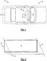
- FIG. 1illustrates a vehicle 10 and a rear view display system 12 of the present invention.
- the rear view display systemincludes a display screen 14 mounted to the vehicle in an easily accessible location for a driver to observe.
- the display screen 14is electronically connected to at least one camera 16 mounted to the rear of the vehicle 10. Multiple cameras 16 may be mounted to the vehicle 10 to provide viewing of different area surrounding the vehicle 10.
- cameras 16may be mounted to capture the "blind spot" area that is typically not shown by rear view mirrors and driver positioning.
- the camera 16may also be a wide angle camera, such that a larger area may be viewed.
- the camera 16 and the display screen 14are connected to an ECU 18 which controls the display screen 14. Because the rear view image provided to the driver is supplied by the camera 16 objects within the passenger compartment will not obstruct the view.
- the camera 16may also be used by other vehicle 10 systems, such as vehicle 10 backing systems and may be packaged separately from an assembly 22.
- the assembly 22may include the display 14 and at least one additional device 20A-E packaged together for mounting.
- the display 14 and additional device 20A-Emay or may not be components of the same vehicle system, but are arranged proximate to one another for assembly in the vehicle 10.
- the assembly 22may provide convenient package of the components to minimize obstruction of the driver's view and/or provide for easy assembly of the components within the vehicle 10.
- a housing 24at least partially contains and secures the assembly 22 including the display 14 and the at least one additional device 20A-E together.
- the display screen 14may be mounted in the traditional rear-view mirror position, proximate to the upper center of the windshield 32. Other mounting positions for the display screen 14 may also be considered. If a hard wire external connection to any of the components 14, 18, and/or 20 is required the connection may extend from the housing 24 toward a portion of the vehicle 10 that will minimize obstruction of the driver's view and sight of the wiring, e.g. from the housing 24 to the roof of the vehicle 10.
- the additional device 20A-Emay be utilized for other vehicle 10 and/or driver assistance systems and be packaged with the display 14 as an assembly 22.
- An ECU 18may also included in the assembly 22.
- the display 14, and at least one additional device 20A-Eare secured together to form the assembly 22.
- the assembly housing 24at least partially contains and secures the display 14 and at least one additional device 20A-E together.
- the housing 24may completely contain the individual components 18 and/or 20A-E for aesthetic purposes or may secure and partially contain the individual components 18 and/or 20A-E while allowing access to each of the components 18 and/or 20A-E.
- the housing 24at least partially defines a chamber 25 for at least partially containing the individual components 18 and/or 20A-E.
- a housing cover 26may be placed over the chamber 25 and secured to a main housing portion 28.
- the cover 26 and main housing portion 28provide an aesthetic exterior for the assembly 22.
- the cover 26defines a plurality of orifices 30 allowing the individual components 18, and/or 20A-E contained within unobstructed access to the exterior of the housing 24. That is the orifices 26 are open to the exterior to allow the sensors and/or cameras 20A-E to collect data exterior to the housing 24 and the vehicle 10.
- the covermay be shaped at several locations 34 to allow access to the interior of the housing 24 for easily mounting the housing 24 on a windshield 32.
- the display screen 14is mounted to the exterior of the main housing portion 28. However, the rear of the display may be accessible from within the chamber 25 for electronically connecting the display screen 14 with the camera 16 and the ECU 18.
- Rear view mirrorsare easily adjustable because the reflection perceived by a driver in a rear view mirror depends highly on the position of the mirror relative to the driver's head. Because a camera(s) 16 is used there is an image on the display screen 14 rather than a reflection in a mirror. Thus, the need for the driver to adjust the display screen 14 to obtain the proper mirror position for seeing the rear view of the vehicle 10 may be reduced or eliminated. However, the position of the display screen 14 may still be adjustable to enhance the individual driver's view of the display screen 14. In one embodiment the ECU 18 may recognize the desired display system 12 settings and position for an individual driver and adjust the display screen 14 accordingly. Additionally, the display screen 14 is shown it be sized the same as the main housing portion 28. However, the display screen 14 may be larger or smaller that the housing 24 to provide the most desirable screen ratio for viewing the image from the rear-facing camera 16.
- the display screen 14shows the rear image when the vehicle 10 is running, regardless of the drive gear of the vehicle 10. That is, the display screen 14 displays an image that shows at least a partial rear view of the vehicle 10 whether the vehicle 10 is in a forward or reverse drive gear.
- the display screen 14may also show at least a partial rear view image while the vehicle 10 is in park as well.
- the image displayedmay be interrupted to change views, such as from one camera 16 to another or by panning a camera 16.
- the imagemay be periodically interrupted, according to the invention, it is continuously showing an image that is showing at least a partial rear view of the vehicle 10 on the display screen 14 while the vehicle 10 is in a drive gear regardless of what drive gear is selected.
- the display system 14according to the invention is used in place of a rear view mirror.
Landscapes
- Engineering & Computer Science (AREA)
- Mechanical Engineering (AREA)
- Multimedia (AREA)
- Closed-Circuit Television Systems (AREA)
- Instrument Panels (AREA)
- Fittings On The Vehicle Exterior For Carrying Loads, And Devices For Holding Or Mounting Articles (AREA)
Description
- The present disclosure relates to automotive vehicles, and more particularly to driver assistance devices for automotive vehicles.
- Rear view mirrors are used to assist a driver in backing up a vehicle and to view vehicles located behind them. Rear view mirrors are typically secured to the top-center of the windshield area for convenience of the driver. However, the mirror may be partially or fully obstructed by window pillars, passengers, luggage, headrests, video monitors or other objects located in the passenger compartment of the vehicle. Additionally, objects such as bike or tire racks may block the rear window of the vehicle also partially or fully obstructing the rear view mirror.
- Additional devices, such as forward looking cameras can be use in collision avoidance systems and sensors may be used for systems such as adaptive cruise control or controlling the windshield wipers. Although these cameras and sensors are usually used by different vehicle systems, they may be mounted to the vehicle in the same area as the rear view mirror. That is, since the rear view mirror is partially obstructing view through the windshield at the rear view mirror mounting location it is desirable to take advantage of this position to mount exterior viewing cameras and sensors to minimize further obstructions through the vehicle windshield.
- Document
US 2006/038668 describes an accessory module is mountable to an interior surface of a vehicle windshield and includes a mounting element securable to an interior surface of a windshield of a vehicle, and an accessory support having a base portion attachable to the mounting element. The accessory support includes an accessory holding element configured to hold an accessory, at least one circuitry holding element configured to hold a printed circuit board at the accessory support, and an electrical connector for electrically connecting the printed circuit board and the accessory to an electrical source of the vehicle. The base portion, the accessory holding element and the circuitry holding element are integrally molded together so that the accessory support comprises a unitarily molded accessory support. DocumentWO02/18174 A1 - A display system according to the invention is defined by the features of claim 1.
- Further areas of applicability of the present disclosure will become apparent from the detailed description provided hereinafter. It should be understood that the detailed description and specific examples, while indicating the preferred embodiment of the disclosure, are intended for purposes of illustration only and are not intended to limit the scope of the disclosure.
- The present disclosure will become more fully understood from the detailed description and the accompanying drawings, wherein:
FIG. 1 is a schematic illustration of a vehicle utilizing a rear view display system of the present invention;FIG. 2 is a schematic perspective illustration of a first view of the rear view display system ofFigure 1 ;FIG. 3 is a schematic perspective illustration of an exploded view of the housing for the rear view display system ofFigures 1-2 ; andFIG. 4 is a schematic perspective illustration of another view of the rear view display system ofFigures 1-2 .- The following description is merely exemplary in nature and is in no way intended to limit the disclosure, its application, or uses. For purposes of clarity, the same reference numbers will be used in the drawings to identify similar elements.
Figure 1 and illustrates avehicle 10 and a rearview display system 12 of the present invention. Throughout the application the relative directions such as forward and rear are in reference to the direction which a driver for thevehicle 10 would primarily be facing when operating thevehicle 10. The rear view display system includes adisplay screen 14 mounted to the vehicle in an easily accessible location for a driver to observe. Thedisplay screen 14 is electronically connected to at least onecamera 16 mounted to the rear of thevehicle 10.Multiple cameras 16 may be mounted to thevehicle 10 to provide viewing of different area surrounding thevehicle 10. For example,cameras 16 may be mounted to capture the "blind spot" area that is typically not shown by rear view mirrors and driver positioning. Thecamera 16 may also be a wide angle camera, such that a larger area may be viewed. Thecamera 16 and thedisplay screen 14 are connected to anECU 18 which controls thedisplay screen 14. Because the rear view image provided to the driver is supplied by thecamera 16 objects within the passenger compartment will not obstruct the view. Thecamera 16 may also be used byother vehicle 10 systems, such asvehicle 10 backing systems and may be packaged separately from anassembly 22. - The
assembly 22 may include thedisplay 14 and at least oneadditional device 20A-E packaged together for mounting. Thedisplay 14 andadditional device 20A-E may or may not be components of the same vehicle system, but are arranged proximate to one another for assembly in thevehicle 10. Theassembly 22 may provide convenient package of the components to minimize obstruction of the driver's view and/or provide for easy assembly of the components within thevehicle 10. Ahousing 24 at least partially contains and secures theassembly 22 including thedisplay 14 and the at least oneadditional device 20A-E together. - The
display screen 14 may be mounted in the traditional rear-view mirror position, proximate to the upper center of thewindshield 32. Other mounting positions for thedisplay screen 14 may also be considered. If a hard wire external connection to any of thecomponents housing 24 toward a portion of thevehicle 10 that will minimize obstruction of the driver's view and sight of the wiring, e.g. from thehousing 24 to the roof of thevehicle 10. - The
additional device 20A-E may be utilized forother vehicle 10 and/or driver assistance systems and be packaged with thedisplay 14 as anassembly 22. An ECU 18 may also included in theassembly 22. For example, theECU 18, a forward looking sensor, such aslidar 20A orradar 20B, atemperature sensor 20C, arain sensor 20D, and/orcameras 20E, lights sensors and even other control units used by other systems for thevehicle 10. - The
display 14, and at least oneadditional device 20A-E are secured together to form theassembly 22. Theassembly housing 24 at least partially contains and secures thedisplay 14 and at least oneadditional device 20A-E together. Thehousing 24 may completely contain theindividual components 18 and/or 20A-E for aesthetic purposes or may secure and partially contain theindividual components 18 and/or 20A-E while allowing access to each of thecomponents 18 and/or 20A-E. - Referring to
Figures 2-4 an example embodiment of ahousing 24 is illustrated. Thehousing 24 at least partially defines a chamber 25 for at least partially containing theindividual components 18 and/or 20A-E.A housing cover 26 may be placed over the chamber 25 and secured to amain housing portion 28. Thecover 26 andmain housing portion 28 provide an aesthetic exterior for theassembly 22. Thecover 26 defines a plurality oforifices 30 allowing theindividual components 18, and/or 20A-E contained within unobstructed access to the exterior of thehousing 24. That is theorifices 26 are open to the exterior to allow the sensors and/orcameras 20A-E to collect data exterior to thehousing 24 and thevehicle 10. Additionally, the cover may be shaped atseveral locations 34 to allow access to the interior of thehousing 24 for easily mounting thehousing 24 on awindshield 32. Thedisplay screen 14 is mounted to the exterior of themain housing portion 28. However, the rear of the display may be accessible from within the chamber 25 for electronically connecting thedisplay screen 14 with thecamera 16 and theECU 18. - Rear view mirrors are easily adjustable because the reflection perceived by a driver in a rear view mirror depends highly on the position of the mirror relative to the driver's head. Because a camera(s) 16 is used there is an image on the
display screen 14 rather than a reflection in a mirror. Thus, the need for the driver to adjust thedisplay screen 14 to obtain the proper mirror position for seeing the rear view of thevehicle 10 may be reduced or eliminated. However, the position of thedisplay screen 14 may still be adjustable to enhance the individual driver's view of thedisplay screen 14. In one embodiment theECU 18 may recognize the desireddisplay system 12 settings and position for an individual driver and adjust thedisplay screen 14 accordingly. Additionally, thedisplay screen 14 is shown it be sized the same as themain housing portion 28. However, thedisplay screen 14 may be larger or smaller that thehousing 24 to provide the most desirable screen ratio for viewing the image from the rear-facingcamera 16. - Although, the image shown may change, the
display screen 14 shows the rear image when thevehicle 10 is running, regardless of the drive gear of thevehicle 10. That is, thedisplay screen 14 displays an image that shows at least a partial rear view of thevehicle 10 whether thevehicle 10 is in a forward or reverse drive gear. Thedisplay screen 14 may also show at least a partial rear view image while thevehicle 10 is in park as well. The image displayed may be interrupted to change views, such as from onecamera 16 to another or by panning acamera 16. However, while the image may be periodically interrupted, according to the invention, it is continuously showing an image that is showing at least a partial rear view of thevehicle 10 on thedisplay screen 14 while thevehicle 10 is in a drive gear regardless of what drive gear is selected. Thus, thedisplay system 14 according to the invention is used in place of a rear view mirror. - While the best modes for carrying out the invention have been described in detail the true scope of the disclosure should not be so limited, since those familiar with the art to which this invention relates will recognize various alternative designs and embodiments for practicing the invention within the scope of the appended claims.
Claims (5)
- A display system (12) for a vehicle (10) comprising:a housing (24), wherein the housing (24) is configured for being mounted to the vehicle (10) and wherein the housing (24) at least partially contains:- a display screen (14) secured to the housing (24), wherein the display screen (14) is configured for showing an image provided by a camera at least partially facing in a rear direction of the vehicle (10), wherein the image on the display screen (14) is shown continuously while the vehicle (10) is in a drive gear,- an ECU (18) mounted within the housing (24) for controlling the image shown on the display; anda temperature sensor (20c), a rain sensor (20d), a forward facing camera, and a lidar (20a) and/or radar sensor (20b) at least one of them used by another system for the vehicle (10), and wherein one of them is at least partially contained within the housing (24), wherein the display system (12) is used in place of a rear view mirror of the vehicle (10).
- The display system (12) of claim 1, wherein the display screen (14) is adjustably secured to the housing.
- The display system (12) of claim 1, wherein the housing (24) further comprises a main housing portion (28) and a cover (26) for at least partially containing the temperature sensor (20c), the rain sensor (20d), the forward facing camera, and the lidar sensor (20a) and/or the radar sensor (20b), and wherein the cover (26) defines at least one orifice (30) for external access by the forward facing camera and at least one orifice (30) for external access by the temperature sensor (20c), the rain sensor (20d), the forward facing camera and the lidar sensor (20a) and/or the radar sensor (20b).
- Vehicle (10) comprising a display system (12) according to one of the preceding claims.
- Use of a display system (12) in place of a rear view mirror of a vehicle (10), wherein the display system (12) comprises:a housing (24), wherein the housing (24) is configured for being mounted to the vehicle (10) and wherein the housing (24) at least partially contains:- a display screen (14) secured to the housing (24), wherein the display screen (14) is configured for showing an image provided by a camera at least partially facing in a rear direction of the vehicle (10) wherein the image on the display screen (14) is shown continuously while the vehicle (10) is in a drive gear,- an ECU (18) mounted within the housing (24) for controlling the image shown on the display; anda temperature sensor (20c), a rain sensor (20d), a forward facing camera, and a lidar (20a) and/or radar sensor (20b) at least one of them used by another system for the vehicle (10), and wherein one of them is at least partially contained within the housing (24), wherein the display system (12) is used in place of a rear view mirror of the vehicle (10).
Applications Claiming Priority (2)
| Application Number | Priority Date | Filing Date | Title |
|---|---|---|---|
| US201161547340P | 2011-10-14 | 2011-10-14 | |
| PCT/US2012/059973WO2013056064A1 (en) | 2011-10-14 | 2012-10-12 | Integrated rear camera display |
Publications (2)
| Publication Number | Publication Date |
|---|---|
| EP2766224A1 EP2766224A1 (en) | 2014-08-20 |
| EP2766224B1true EP2766224B1 (en) | 2018-12-26 |
Family
ID=47148930
Family Applications (1)
| Application Number | Title | Priority Date | Filing Date |
|---|---|---|---|
| EP12784134.4AActiveEP2766224B1 (en) | 2011-10-14 | 2012-10-12 | Integrated rear camera display |
Country Status (3)
| Country | Link |
|---|---|
| US (1) | US20130093584A1 (en) |
| EP (1) | EP2766224B1 (en) |
| WO (1) | WO2013056064A1 (en) |
Cited By (5)
| Publication number | Priority date | Publication date | Assignee | Title |
|---|---|---|---|---|
| US11901601B2 (en) | 2020-12-18 | 2024-02-13 | Aptiv Technologies Limited | Waveguide with a zigzag for suppressing grating lobes |
| US11949145B2 (en) | 2021-08-03 | 2024-04-02 | Aptiv Technologies AG | Transition formed of LTCC material and having stubs that match input impedances between a single-ended port and differential ports |
| US11962085B2 (en) | 2021-05-13 | 2024-04-16 | Aptiv Technologies AG | Two-part folded waveguide having a sinusoidal shape channel including horn shape radiating slots formed therein which are spaced apart by one-half wavelength |
| US12058804B2 (en) | 2021-02-09 | 2024-08-06 | Aptiv Technologies AG | Formed waveguide antennas of a radar assembly |
| US12148992B2 (en) | 2023-01-25 | 2024-11-19 | Aptiv Technologies AG | Hybrid horn waveguide antenna |
Families Citing this family (21)
| Publication number | Priority date | Publication date | Assignee | Title |
|---|---|---|---|---|
| US20150042874A1 (en)* | 2013-08-08 | 2015-02-12 | Nidec Elesys Corporation | In-vehicle camera |
| US10838062B2 (en) | 2016-05-24 | 2020-11-17 | Veoneer Us, Inc. | Direct detection LiDAR system and method with pulse amplitude modulation (AM) transmitter and quadrature receiver |
| US10416292B2 (en) | 2016-05-24 | 2019-09-17 | Veoneer Us, Inc. | Direct detection LiDAR system and method with frequency modulation (FM) transmitter and quadrature receiver |
| US10473784B2 (en) | 2016-05-24 | 2019-11-12 | Veoneer Us, Inc. | Direct detection LiDAR system and method with step frequency modulation (FM) pulse-burst envelope modulation transmission and quadrature demodulation |
| JP6988409B2 (en) | 2017-04-03 | 2022-01-05 | 株式会社デンソー | The camera module |
| US11460550B2 (en) | 2017-09-19 | 2022-10-04 | Veoneer Us, Llc | Direct detection LiDAR system and method with synthetic doppler processing |
| US10838043B2 (en) | 2017-11-15 | 2020-11-17 | Veoneer Us, Inc. | Scanning LiDAR system and method with spatial filtering for reduction of ambient light |
| US10613200B2 (en) | 2017-09-19 | 2020-04-07 | Veoneer, Inc. | Scanning lidar system and method |
| US10684370B2 (en) | 2017-09-29 | 2020-06-16 | Veoneer Us, Inc. | Multifunction vehicle detection system |
| US11194022B2 (en) | 2017-09-29 | 2021-12-07 | Veoneer Us, Inc. | Detection system with reflection member and offset detection array |
| US11585901B2 (en) | 2017-11-15 | 2023-02-21 | Veoneer Us, Llc | Scanning lidar system and method with spatial filtering for reduction of ambient light |
| US11474218B2 (en) | 2019-07-15 | 2022-10-18 | Veoneer Us, Llc | Scanning LiDAR system and method with unitary optical element |
| US11579257B2 (en) | 2019-07-15 | 2023-02-14 | Veoneer Us, Llc | Scanning LiDAR system and method with unitary optical element |
| US11313969B2 (en) | 2019-10-28 | 2022-04-26 | Veoneer Us, Inc. | LiDAR homodyne transceiver using pulse-position modulation |
| US12044800B2 (en) | 2021-01-14 | 2024-07-23 | Magna Electronics, Llc | Scanning LiDAR system and method with compensation for transmit laser pulse effects |
| US11326758B1 (en) | 2021-03-12 | 2022-05-10 | Veoneer Us, Inc. | Spotlight illumination system using optical element |
| US11732858B2 (en) | 2021-06-18 | 2023-08-22 | Veoneer Us, Llc | Headlight illumination system using optical element |
| EP4191274A1 (en) | 2021-12-03 | 2023-06-07 | Aptiv Technologies Limited | Radar-based estimation of the height of an object |
| US12228653B2 (en) | 2022-10-07 | 2025-02-18 | Magna Electronics, Llc | Integrating a sensing system into headlight optics |
| US12092278B2 (en) | 2022-10-07 | 2024-09-17 | Magna Electronics, Llc | Generating a spotlight |
| US12202396B1 (en) | 2023-12-19 | 2025-01-21 | Magna Electronics, Llc | Line-scan-gated imaging for LiDAR headlight |
Citations (5)
| Publication number | Priority date | Publication date | Assignee | Title |
|---|---|---|---|---|
| US6281804B1 (en)* | 1996-09-27 | 2001-08-28 | Daimlerchrysler Ag | Display arranged in a motor vehicle |
| WO2002018174A1 (en)* | 2000-09-01 | 2002-03-07 | Robert Bosch Gmbh | Rearview mirror device for a motor vehicle |
| US20070153085A1 (en)* | 2006-01-02 | 2007-07-05 | Ching-Shan Chang | Rear-view mirror with front and rear bidirectional lens and screen for displaying images |
| JP2009100180A (en)* | 2007-10-16 | 2009-05-07 | Denso Corp | Vehicular rear monitoring device |
| WO2011042850A1 (en)* | 2009-10-05 | 2011-04-14 | David Bellingham | An automobile rear view mirror assembly |
Family Cites Families (10)
| Publication number | Priority date | Publication date | Assignee | Title |
|---|---|---|---|---|
| US6243003B1 (en)* | 1999-08-25 | 2001-06-05 | Donnelly Corporation | Accessory module for vehicle |
| US7480149B2 (en)* | 2004-08-18 | 2009-01-20 | Donnelly Corporation | Accessory module for vehicle |
| DE10036570B4 (en)* | 2000-07-27 | 2004-07-15 | Robert Bosch Gmbh | display device |
| US20030090568A1 (en)* | 2001-04-23 | 2003-05-15 | Pico Thomas Michael | Digital imaging rear view mirror system |
| WO2003065084A1 (en)* | 2002-01-31 | 2003-08-07 | Donnelly Corporation | Vehicle accessory module |
| US20060093094A1 (en)* | 2004-10-15 | 2006-05-04 | Zhu Xing | Automatic measurement and announcement voice quality testing system |
| WO2006063827A1 (en)* | 2004-12-15 | 2006-06-22 | Magna Donnelly Electronics Naas Limited | An accessory module system for a vehicle window |
| CN101263027A (en)* | 2005-09-16 | 2008-09-10 | 夏普株式会社 | Display system, screen design setting tool, program for display system, screen design setting program, and storage medium |
| WO2010099416A1 (en)* | 2009-02-27 | 2010-09-02 | Magna Electronics | Alert system for vehicle |
| JP5271154B2 (en)* | 2009-05-29 | 2013-08-21 | 富士通テン株式会社 | Image generating apparatus and image display system |
- 2012
- 2012-10-12EPEP12784134.4Apatent/EP2766224B1/enactiveActive
- 2012-10-12WOPCT/US2012/059973patent/WO2013056064A1/enactiveApplication Filing
- 2012-10-12USUS13/650,362patent/US20130093584A1/ennot_activeAbandoned
Patent Citations (5)
| Publication number | Priority date | Publication date | Assignee | Title |
|---|---|---|---|---|
| US6281804B1 (en)* | 1996-09-27 | 2001-08-28 | Daimlerchrysler Ag | Display arranged in a motor vehicle |
| WO2002018174A1 (en)* | 2000-09-01 | 2002-03-07 | Robert Bosch Gmbh | Rearview mirror device for a motor vehicle |
| US20070153085A1 (en)* | 2006-01-02 | 2007-07-05 | Ching-Shan Chang | Rear-view mirror with front and rear bidirectional lens and screen for displaying images |
| JP2009100180A (en)* | 2007-10-16 | 2009-05-07 | Denso Corp | Vehicular rear monitoring device |
| WO2011042850A1 (en)* | 2009-10-05 | 2011-04-14 | David Bellingham | An automobile rear view mirror assembly |
Cited By (5)
| Publication number | Priority date | Publication date | Assignee | Title |
|---|---|---|---|---|
| US11901601B2 (en) | 2020-12-18 | 2024-02-13 | Aptiv Technologies Limited | Waveguide with a zigzag for suppressing grating lobes |
| US12058804B2 (en) | 2021-02-09 | 2024-08-06 | Aptiv Technologies AG | Formed waveguide antennas of a radar assembly |
| US11962085B2 (en) | 2021-05-13 | 2024-04-16 | Aptiv Technologies AG | Two-part folded waveguide having a sinusoidal shape channel including horn shape radiating slots formed therein which are spaced apart by one-half wavelength |
| US11949145B2 (en) | 2021-08-03 | 2024-04-02 | Aptiv Technologies AG | Transition formed of LTCC material and having stubs that match input impedances between a single-ended port and differential ports |
| US12148992B2 (en) | 2023-01-25 | 2024-11-19 | Aptiv Technologies AG | Hybrid horn waveguide antenna |
Also Published As
| Publication number | Publication date |
|---|---|
| EP2766224A1 (en) | 2014-08-20 |
| WO2013056064A1 (en) | 2013-04-18 |
| US20130093584A1 (en) | 2013-04-18 |
Similar Documents
| Publication | Publication Date | Title |
|---|---|---|
| EP2766224B1 (en) | Integrated rear camera display | |
| US12391180B2 (en) | Vehicular exterior rearview mirror assembly | |
| EP2773532B1 (en) | Vision system with door mounted exterior mirror and display | |
| US6087953A (en) | Rearview mirror support incorporating vehicle information display | |
| US6172613B1 (en) | Rearview mirror assembly incorporating vehicle information display | |
| US7722199B2 (en) | Vehicle interior rearview mirror assembly with actuator | |
| US8451332B2 (en) | Interior mirror assembly with adjustable mounting assembly | |
| US9327649B2 (en) | Rearview mirror assembly | |
| US20170355312A1 (en) | Interior rearview mirror assembly with full screen video display | |
| US20030202096A1 (en) | Apparatus for monitoring rear of vehicle | |
| US8414137B2 (en) | Inside rearview mirror assembly | |
| US20070147660A1 (en) | Image processing system for motor vehicles | |
| US20230078512A1 (en) | Overhead console accessory system with shared controls, cameras, and lighting | |
| US20190041222A1 (en) | Full width cross vehicle display | |
| KR100971453B1 (en) | Car rearview system | |
| KR19980043660U (en) | Rear information display device of car |
Legal Events
| Date | Code | Title | Description |
|---|---|---|---|
| PUAI | Public reference made under article 153(3) epc to a published international application that has entered the european phase | Free format text:ORIGINAL CODE: 0009012 | |
| 17P | Request for examination filed | Effective date:20140509 | |
| AK | Designated contracting states | Kind code of ref document:A1 Designated state(s):AL AT BE BG CH CY CZ DE DK EE ES FI FR GB GR HR HU IE IS IT LI LT LU LV MC MK MT NL NO PL PT RO RS SE SI SK SM TR | |
| DAX | Request for extension of the european patent (deleted) | ||
| 17Q | First examination report despatched | Effective date:20160927 | |
| STAA | Information on the status of an ep patent application or granted ep patent | Free format text:STATUS: EXAMINATION IS IN PROGRESS | |
| GRAP | Despatch of communication of intention to grant a patent | Free format text:ORIGINAL CODE: EPIDOSNIGR1 | |
| STAA | Information on the status of an ep patent application or granted ep patent | Free format text:STATUS: GRANT OF PATENT IS INTENDED | |
| INTG | Intention to grant announced | Effective date:20180831 | |
| GRAS | Grant fee paid | Free format text:ORIGINAL CODE: EPIDOSNIGR3 | |
| GRAA | (expected) grant | Free format text:ORIGINAL CODE: 0009210 | |
| STAA | Information on the status of an ep patent application or granted ep patent | Free format text:STATUS: THE PATENT HAS BEEN GRANTED | |
| AK | Designated contracting states | Kind code of ref document:B1 Designated state(s):AL AT BE BG CH CY CZ DE DK EE ES FI FR GB GR HR HU IE IS IT LI LT LU LV MC MK MT NL NO PL PT RO RS SE SI SK SM TR | |
| REG | Reference to a national code | Ref country code:GB Ref legal event code:FG4D | |
| REG | Reference to a national code | Ref country code:CH Ref legal event code:EP | |
| REG | Reference to a national code | Ref country code:AT Ref legal event code:REF Ref document number:1080956 Country of ref document:AT Kind code of ref document:T Effective date:20190115 | |
| REG | Reference to a national code | Ref country code:DE Ref legal event code:R096 Ref document number:602012055187 Country of ref document:DE | |
| REG | Reference to a national code | Ref country code:IE Ref legal event code:FG4D | |
| REG | Reference to a national code | Ref country code:SE Ref legal event code:TRGR | |
| PG25 | Lapsed in a contracting state [announced via postgrant information from national office to epo] | Ref country code:HR Free format text:LAPSE BECAUSE OF FAILURE TO SUBMIT A TRANSLATION OF THE DESCRIPTION OR TO PAY THE FEE WITHIN THE PRESCRIBED TIME-LIMIT Effective date:20181226 Ref country code:NO Free format text:LAPSE BECAUSE OF FAILURE TO SUBMIT A TRANSLATION OF THE DESCRIPTION OR TO PAY THE FEE WITHIN THE PRESCRIBED TIME-LIMIT Effective date:20190326 Ref country code:LV Free format text:LAPSE BECAUSE OF FAILURE TO SUBMIT A TRANSLATION OF THE DESCRIPTION OR TO PAY THE FEE WITHIN THE PRESCRIBED TIME-LIMIT Effective date:20181226 Ref country code:FI Free format text:LAPSE BECAUSE OF FAILURE TO SUBMIT A TRANSLATION OF THE DESCRIPTION OR TO PAY THE FEE WITHIN THE PRESCRIBED TIME-LIMIT Effective date:20181226 Ref country code:BG Free format text:LAPSE BECAUSE OF FAILURE TO SUBMIT A TRANSLATION OF THE DESCRIPTION OR TO PAY THE FEE WITHIN THE PRESCRIBED TIME-LIMIT Effective date:20190326 Ref country code:LT Free format text:LAPSE BECAUSE OF FAILURE TO SUBMIT A TRANSLATION OF THE DESCRIPTION OR TO PAY THE FEE WITHIN THE PRESCRIBED TIME-LIMIT Effective date:20181226 | |
| REG | Reference to a national code | Ref country code:NL Ref legal event code:MP Effective date:20181226 | |
| REG | Reference to a national code | Ref country code:LT Ref legal event code:MG4D | |
| PG25 | Lapsed in a contracting state [announced via postgrant information from national office to epo] | Ref country code:GR Free format text:LAPSE BECAUSE OF FAILURE TO SUBMIT A TRANSLATION OF THE DESCRIPTION OR TO PAY THE FEE WITHIN THE PRESCRIBED TIME-LIMIT Effective date:20190327 Ref country code:AL Free format text:LAPSE BECAUSE OF FAILURE TO SUBMIT A TRANSLATION OF THE DESCRIPTION OR TO PAY THE FEE WITHIN THE PRESCRIBED TIME-LIMIT Effective date:20181226 Ref country code:RS Free format text:LAPSE BECAUSE OF FAILURE TO SUBMIT A TRANSLATION OF THE DESCRIPTION OR TO PAY THE FEE WITHIN THE PRESCRIBED TIME-LIMIT Effective date:20181226 | |
| REG | Reference to a national code | Ref country code:AT Ref legal event code:MK05 Ref document number:1080956 Country of ref document:AT Kind code of ref document:T Effective date:20181226 | |
| PG25 | Lapsed in a contracting state [announced via postgrant information from national office to epo] | Ref country code:NL Free format text:LAPSE BECAUSE OF FAILURE TO SUBMIT A TRANSLATION OF THE DESCRIPTION OR TO PAY THE FEE WITHIN THE PRESCRIBED TIME-LIMIT Effective date:20181226 | |
| PG25 | Lapsed in a contracting state [announced via postgrant information from national office to epo] | Ref country code:PL Free format text:LAPSE BECAUSE OF FAILURE TO SUBMIT A TRANSLATION OF THE DESCRIPTION OR TO PAY THE FEE WITHIN THE PRESCRIBED TIME-LIMIT Effective date:20181226 Ref country code:ES Free format text:LAPSE BECAUSE OF FAILURE TO SUBMIT A TRANSLATION OF THE DESCRIPTION OR TO PAY THE FEE WITHIN THE PRESCRIBED TIME-LIMIT Effective date:20181226 Ref country code:CZ Free format text:LAPSE BECAUSE OF FAILURE TO SUBMIT A TRANSLATION OF THE DESCRIPTION OR TO PAY THE FEE WITHIN THE PRESCRIBED TIME-LIMIT Effective date:20181226 Ref country code:IT Free format text:LAPSE BECAUSE OF FAILURE TO SUBMIT A TRANSLATION OF THE DESCRIPTION OR TO PAY THE FEE WITHIN THE PRESCRIBED TIME-LIMIT Effective date:20181226 Ref country code:PT Free format text:LAPSE BECAUSE OF FAILURE TO SUBMIT A TRANSLATION OF THE DESCRIPTION OR TO PAY THE FEE WITHIN THE PRESCRIBED TIME-LIMIT Effective date:20190426 | |
| PG25 | Lapsed in a contracting state [announced via postgrant information from national office to epo] | Ref country code:RO Free format text:LAPSE BECAUSE OF FAILURE TO SUBMIT A TRANSLATION OF THE DESCRIPTION OR TO PAY THE FEE WITHIN THE PRESCRIBED TIME-LIMIT Effective date:20181226 Ref country code:SK Free format text:LAPSE BECAUSE OF FAILURE TO SUBMIT A TRANSLATION OF THE DESCRIPTION OR TO PAY THE FEE WITHIN THE PRESCRIBED TIME-LIMIT Effective date:20181226 Ref country code:SM Free format text:LAPSE BECAUSE OF FAILURE TO SUBMIT A TRANSLATION OF THE DESCRIPTION OR TO PAY THE FEE WITHIN THE PRESCRIBED TIME-LIMIT Effective date:20181226 Ref country code:EE Free format text:LAPSE BECAUSE OF FAILURE TO SUBMIT A TRANSLATION OF THE DESCRIPTION OR TO PAY THE FEE WITHIN THE PRESCRIBED TIME-LIMIT Effective date:20181226 Ref country code:IS Free format text:LAPSE BECAUSE OF FAILURE TO SUBMIT A TRANSLATION OF THE DESCRIPTION OR TO PAY THE FEE WITHIN THE PRESCRIBED TIME-LIMIT Effective date:20190426 | |
| REG | Reference to a national code | Ref country code:DE Ref legal event code:R097 Ref document number:602012055187 Country of ref document:DE | |
| PG25 | Lapsed in a contracting state [announced via postgrant information from national office to epo] | Ref country code:DK Free format text:LAPSE BECAUSE OF FAILURE TO SUBMIT A TRANSLATION OF THE DESCRIPTION OR TO PAY THE FEE WITHIN THE PRESCRIBED TIME-LIMIT Effective date:20181226 Ref country code:AT Free format text:LAPSE BECAUSE OF FAILURE TO SUBMIT A TRANSLATION OF THE DESCRIPTION OR TO PAY THE FEE WITHIN THE PRESCRIBED TIME-LIMIT Effective date:20181226 | |
| PLBE | No opposition filed within time limit | Free format text:ORIGINAL CODE: 0009261 | |
| STAA | Information on the status of an ep patent application or granted ep patent | Free format text:STATUS: NO OPPOSITION FILED WITHIN TIME LIMIT | |
| 26N | No opposition filed | Effective date:20190927 | |
| PG25 | Lapsed in a contracting state [announced via postgrant information from national office to epo] | Ref country code:SI Free format text:LAPSE BECAUSE OF FAILURE TO SUBMIT A TRANSLATION OF THE DESCRIPTION OR TO PAY THE FEE WITHIN THE PRESCRIBED TIME-LIMIT Effective date:20181226 | |
| PG25 | Lapsed in a contracting state [announced via postgrant information from national office to epo] | Ref country code:TR Free format text:LAPSE BECAUSE OF FAILURE TO SUBMIT A TRANSLATION OF THE DESCRIPTION OR TO PAY THE FEE WITHIN THE PRESCRIBED TIME-LIMIT Effective date:20181226 | |
| PG25 | Lapsed in a contracting state [announced via postgrant information from national office to epo] | Ref country code:MC Free format text:LAPSE BECAUSE OF FAILURE TO SUBMIT A TRANSLATION OF THE DESCRIPTION OR TO PAY THE FEE WITHIN THE PRESCRIBED TIME-LIMIT Effective date:20181226 | |
| REG | Reference to a national code | Ref country code:CH Ref legal event code:PL | |
| PG25 | Lapsed in a contracting state [announced via postgrant information from national office to epo] | Ref country code:LU Free format text:LAPSE BECAUSE OF NON-PAYMENT OF DUE FEES Effective date:20191012 Ref country code:CH Free format text:LAPSE BECAUSE OF NON-PAYMENT OF DUE FEES Effective date:20191031 Ref country code:LI Free format text:LAPSE BECAUSE OF NON-PAYMENT OF DUE FEES Effective date:20191031 | |
| REG | Reference to a national code | Ref country code:BE Ref legal event code:MM Effective date:20191031 | |
| PG25 | Lapsed in a contracting state [announced via postgrant information from national office to epo] | Ref country code:BE Free format text:LAPSE BECAUSE OF NON-PAYMENT OF DUE FEES Effective date:20191031 | |
| PG25 | Lapsed in a contracting state [announced via postgrant information from national office to epo] | Ref country code:IE Free format text:LAPSE BECAUSE OF NON-PAYMENT OF DUE FEES Effective date:20191012 | |
| PG25 | Lapsed in a contracting state [announced via postgrant information from national office to epo] | Ref country code:CY Free format text:LAPSE BECAUSE OF FAILURE TO SUBMIT A TRANSLATION OF THE DESCRIPTION OR TO PAY THE FEE WITHIN THE PRESCRIBED TIME-LIMIT Effective date:20181226 | |
| PG25 | Lapsed in a contracting state [announced via postgrant information from national office to epo] | Ref country code:HU Free format text:LAPSE BECAUSE OF FAILURE TO SUBMIT A TRANSLATION OF THE DESCRIPTION OR TO PAY THE FEE WITHIN THE PRESCRIBED TIME-LIMIT; INVALID AB INITIO Effective date:20121012 Ref country code:MT Free format text:LAPSE BECAUSE OF FAILURE TO SUBMIT A TRANSLATION OF THE DESCRIPTION OR TO PAY THE FEE WITHIN THE PRESCRIBED TIME-LIMIT Effective date:20181226 | |
| PG25 | Lapsed in a contracting state [announced via postgrant information from national office to epo] | Ref country code:MK Free format text:LAPSE BECAUSE OF FAILURE TO SUBMIT A TRANSLATION OF THE DESCRIPTION OR TO PAY THE FEE WITHIN THE PRESCRIBED TIME-LIMIT Effective date:20181226 | |
| REG | Reference to a national code | Ref country code:DE Ref legal event code:R081 Ref document number:602012055187 Country of ref document:DE Owner name:CONTINENTAL AUTONOMOUS MOBILITY US, LLC (N.D.G, US Free format text:FORMER OWNER: CONTINENTAL AUTOMOTIVE SYSTEMS, INC., AUBURN HILLS, MICH., US | |
| PGFP | Annual fee paid to national office [announced via postgrant information from national office to epo] | Ref country code:DE Payment date:20241031 Year of fee payment:13 | |
| PGFP | Annual fee paid to national office [announced via postgrant information from national office to epo] | Ref country code:GB Payment date:20241025 Year of fee payment:13 | |
| PGFP | Annual fee paid to national office [announced via postgrant information from national office to epo] | Ref country code:FR Payment date:20241021 Year of fee payment:13 | |
| PGFP | Annual fee paid to national office [announced via postgrant information from national office to epo] | Ref country code:SE Payment date:20241021 Year of fee payment:13 |