EP2758979B1 - Cold plasma delivery system and associated method - Google Patents
Cold plasma delivery system and associated methodDownload PDFInfo
- Publication number
- EP2758979B1 EP2758979B1EP12838901.2AEP12838901AEP2758979B1EP 2758979 B1EP2758979 B1EP 2758979B1EP 12838901 AEP12838901 AEP 12838901AEP 2758979 B1EP2758979 B1EP 2758979B1
- Authority
- EP
- European Patent Office
- Prior art keywords
- cold plasma
- gas
- cartridge
- high voltage
- gas cartridge
- Prior art date
- Legal status (The legal status is an assumption and is not a legal conclusion. Google has not performed a legal analysis and makes no representation as to the accuracy of the status listed.)
- Active
Links
- 230000005495cold plasmaEffects0.000titleclaimsdescription114
- 238000000034methodMethods0.000titleclaimsdescription30
- 230000013011matingEffects0.000claimsdescription24
- 238000011282treatmentMethods0.000claimsdescription16
- 230000004044responseEffects0.000claimsdescription9
- 238000003860storageMethods0.000claimsdescription5
- 239000002184metalSubstances0.000claimsdescription4
- 238000000968medical method and processMethods0.000claims2
- 230000008878couplingEffects0.000claims1
- 238000010168coupling processMethods0.000claims1
- 238000005859coupling reactionMethods0.000claims1
- 239000007789gasSubstances0.000description126
- 210000002381plasmaAnatomy0.000description21
- 239000000203mixtureSubstances0.000description9
- 230000008569processEffects0.000description8
- 239000003990capacitorSubstances0.000description6
- 238000010791quenchingMethods0.000description6
- 238000004804windingMethods0.000description6
- 229910052734heliumInorganic materials0.000description5
- 239000001307heliumSubstances0.000description5
- SWQJXJOGLNCZEY-UHFFFAOYSA-Nhelium atomChemical compound[He]SWQJXJOGLNCZEY-UHFFFAOYSA-N0.000description5
- 238000009832plasma treatmentMethods0.000description5
- XKRFYHLGVUSROY-UHFFFAOYSA-NArgonChemical compound[Ar]XKRFYHLGVUSROY-UHFFFAOYSA-N0.000description4
- 206010052428WoundDiseases0.000description4
- 230000015556catabolic processEffects0.000description4
- 230000006698inductionEffects0.000description4
- 238000004519manufacturing processMethods0.000description4
- 208000027418Wounds and injuryDiseases0.000description3
- 230000006870functionEffects0.000description3
- 239000000463materialSubstances0.000description3
- 229910052756noble gasInorganic materials0.000description3
- 238000004806packaging method and processMethods0.000description3
- 230000000171quenching effectEffects0.000description3
- 230000001954sterilising effectEffects0.000description3
- 238000004659sterilization and disinfectionMethods0.000description3
- 229910052786argonInorganic materials0.000description2
- 230000008901benefitEffects0.000description2
- 238000006731degradation reactionMethods0.000description2
- 230000036512infertilityEffects0.000description2
- 238000013021overheatingMethods0.000description2
- 244000052769pathogenSpecies0.000description2
- 230000001681protective effectEffects0.000description2
- 230000009467reductionEffects0.000description2
- 238000011269treatment regimenMethods0.000description2
- 230000029663wound healingEffects0.000description2
- 208000034693LacerationDiseases0.000description1
- 230000009471actionEffects0.000description1
- 230000000844anti-bacterial effectEffects0.000description1
- 238000013459approachMethods0.000description1
- 230000001580bacterial effectEffects0.000description1
- 230000009286beneficial effectEffects0.000description1
- 230000033228biological regulationEffects0.000description1
- 238000000576coating methodMethods0.000description1
- 230000001419dependent effectEffects0.000description1
- 238000013461designMethods0.000description1
- 238000011161developmentMethods0.000description1
- 230000018109developmental processEffects0.000description1
- 238000010586diagramMethods0.000description1
- 238000011156evaluationMethods0.000description1
- 239000012530fluidSubstances0.000description1
- 239000003574free electronSubstances0.000description1
- 230000035876healingEffects0.000description1
- 238000013160medical therapyMethods0.000description1
- 239000007769metal materialSubstances0.000description1
- 150000002835noble gasesChemical class0.000description1
- 238000011369optimal treatmentMethods0.000description1
- 239000002245particleSubstances0.000description1
- 230000001105regulatory effectEffects0.000description1
- 238000011160researchMethods0.000description1
- 238000002560therapeutic procedureMethods0.000description1
- XLYOFNOQVPJJNP-UHFFFAOYSA-NwaterChemical compoundOXLYOFNOQVPJJNP-UHFFFAOYSA-N0.000description1
Images


Classifications
- H—ELECTRICITY
- H05—ELECTRIC TECHNIQUES NOT OTHERWISE PROVIDED FOR
- H05H—PLASMA TECHNIQUE; PRODUCTION OF ACCELERATED ELECTRICALLY-CHARGED PARTICLES OR OF NEUTRONS; PRODUCTION OR ACCELERATION OF NEUTRAL MOLECULAR OR ATOMIC BEAMS
- H05H1/00—Generating plasma; Handling plasma
- H05H1/24—Generating plasma
- H05H1/46—Generating plasma using applied electromagnetic fields, e.g. high frequency or microwave energy
- A—HUMAN NECESSITIES
- A61—MEDICAL OR VETERINARY SCIENCE; HYGIENE
- A61L—METHODS OR APPARATUS FOR STERILISING MATERIALS OR OBJECTS IN GENERAL; DISINFECTION, STERILISATION OR DEODORISATION OF AIR; CHEMICAL ASPECTS OF BANDAGES, DRESSINGS, ABSORBENT PADS OR SURGICAL ARTICLES; MATERIALS FOR BANDAGES, DRESSINGS, ABSORBENT PADS OR SURGICAL ARTICLES
- A61L2/00—Methods or apparatus for disinfecting or sterilising materials or objects other than foodstuffs or contact lenses; Accessories therefor
- A61L2/0005—Methods or apparatus for disinfecting or sterilising materials or objects other than foodstuffs or contact lenses; Accessories therefor for pharmaceuticals, biologicals or living parts
- A61L2/0011—Methods or apparatus for disinfecting or sterilising materials or objects other than foodstuffs or contact lenses; Accessories therefor for pharmaceuticals, biologicals or living parts using physical methods
- A—HUMAN NECESSITIES
- A61—MEDICAL OR VETERINARY SCIENCE; HYGIENE
- A61L—METHODS OR APPARATUS FOR STERILISING MATERIALS OR OBJECTS IN GENERAL; DISINFECTION, STERILISATION OR DEODORISATION OF AIR; CHEMICAL ASPECTS OF BANDAGES, DRESSINGS, ABSORBENT PADS OR SURGICAL ARTICLES; MATERIALS FOR BANDAGES, DRESSINGS, ABSORBENT PADS OR SURGICAL ARTICLES
- A61L2/00—Methods or apparatus for disinfecting or sterilising materials or objects other than foodstuffs or contact lenses; Accessories therefor
- A61L2/0005—Methods or apparatus for disinfecting or sterilising materials or objects other than foodstuffs or contact lenses; Accessories therefor for pharmaceuticals, biologicals or living parts
- A61L2/0082—Methods or apparatus for disinfecting or sterilising materials or objects other than foodstuffs or contact lenses; Accessories therefor for pharmaceuticals, biologicals or living parts using chemical substances
- A61L2/0094—Gaseous substances
- A—HUMAN NECESSITIES
- A61—MEDICAL OR VETERINARY SCIENCE; HYGIENE
- A61L—METHODS OR APPARATUS FOR STERILISING MATERIALS OR OBJECTS IN GENERAL; DISINFECTION, STERILISATION OR DEODORISATION OF AIR; CHEMICAL ASPECTS OF BANDAGES, DRESSINGS, ABSORBENT PADS OR SURGICAL ARTICLES; MATERIALS FOR BANDAGES, DRESSINGS, ABSORBENT PADS OR SURGICAL ARTICLES
- A61L2/00—Methods or apparatus for disinfecting or sterilising materials or objects other than foodstuffs or contact lenses; Accessories therefor
- A61L2/02—Methods or apparatus for disinfecting or sterilising materials or objects other than foodstuffs or contact lenses; Accessories therefor using physical phenomena
- A61L2/14—Plasma, i.e. ionised gases
- A—HUMAN NECESSITIES
- A61—MEDICAL OR VETERINARY SCIENCE; HYGIENE
- A61M—DEVICES FOR INTRODUCING MEDIA INTO, OR ONTO, THE BODY; DEVICES FOR TRANSDUCING BODY MEDIA OR FOR TAKING MEDIA FROM THE BODY; DEVICES FOR PRODUCING OR ENDING SLEEP OR STUPOR
- A61M15/00—Inhalators
- A61M15/02—Inhalators with activated or ionised fluids, e.g. electrohydrodynamic [EHD] or electrostatic devices; Ozone-inhalators with radioactive tagged particles
- A—HUMAN NECESSITIES
- A61—MEDICAL OR VETERINARY SCIENCE; HYGIENE
- A61M—DEVICES FOR INTRODUCING MEDIA INTO, OR ONTO, THE BODY; DEVICES FOR TRANSDUCING BODY MEDIA OR FOR TAKING MEDIA FROM THE BODY; DEVICES FOR PRODUCING OR ENDING SLEEP OR STUPOR
- A61M16/00—Devices for influencing the respiratory system of patients by gas treatment, e.g. ventilators; Tracheal tubes
- A61M16/06—Respiratory or anaesthetic masks
- A—HUMAN NECESSITIES
- A61—MEDICAL OR VETERINARY SCIENCE; HYGIENE
- A61M—DEVICES FOR INTRODUCING MEDIA INTO, OR ONTO, THE BODY; DEVICES FOR TRANSDUCING BODY MEDIA OR FOR TAKING MEDIA FROM THE BODY; DEVICES FOR PRODUCING OR ENDING SLEEP OR STUPOR
- A61M16/00—Devices for influencing the respiratory system of patients by gas treatment, e.g. ventilators; Tracheal tubes
- A61M16/10—Preparation of respiratory gases or vapours
- A61M16/12—Preparation of respiratory gases or vapours by mixing different gases
- A—HUMAN NECESSITIES
- A61—MEDICAL OR VETERINARY SCIENCE; HYGIENE
- A61N—ELECTROTHERAPY; MAGNETOTHERAPY; RADIATION THERAPY; ULTRASOUND THERAPY
- A61N1/00—Electrotherapy; Circuits therefor
- A61N1/40—Applying electric fields by inductive or capacitive coupling ; Applying radio-frequency signals
- A—HUMAN NECESSITIES
- A61—MEDICAL OR VETERINARY SCIENCE; HYGIENE
- A61N—ELECTROTHERAPY; MAGNETOTHERAPY; RADIATION THERAPY; ULTRASOUND THERAPY
- A61N1/00—Electrotherapy; Circuits therefor
- A61N1/44—Applying ionised fluids
- H—ELECTRICITY
- H01—ELECTRIC ELEMENTS
- H01J—ELECTRIC DISCHARGE TUBES OR DISCHARGE LAMPS
- H01J37/00—Discharge tubes with provision for introducing objects or material to be exposed to the discharge, e.g. for the purpose of examination or processing thereof
- H01J37/32—Gas-filled discharge tubes
- H01J37/32009—Arrangements for generation of plasma specially adapted for examination or treatment of objects, e.g. plasma sources
- H01J37/32082—Radio frequency generated discharge
- H01J37/321—Radio frequency generated discharge the radio frequency energy being inductively coupled to the plasma
- H—ELECTRICITY
- H01—ELECTRIC ELEMENTS
- H01J—ELECTRIC DISCHARGE TUBES OR DISCHARGE LAMPS
- H01J37/00—Discharge tubes with provision for introducing objects or material to be exposed to the discharge, e.g. for the purpose of examination or processing thereof
- H01J37/32—Gas-filled discharge tubes
- H01J37/32009—Arrangements for generation of plasma specially adapted for examination or treatment of objects, e.g. plasma sources
- H01J37/32348—Dielectric barrier discharge
- H—ELECTRICITY
- H01—ELECTRIC ELEMENTS
- H01J—ELECTRIC DISCHARGE TUBES OR DISCHARGE LAMPS
- H01J37/00—Discharge tubes with provision for introducing objects or material to be exposed to the discharge, e.g. for the purpose of examination or processing thereof
- H01J37/32—Gas-filled discharge tubes
- H01J37/32431—Constructional details of the reactor
- H01J37/3244—Gas supply means
- H—ELECTRICITY
- H01—ELECTRIC ELEMENTS
- H01J—ELECTRIC DISCHARGE TUBES OR DISCHARGE LAMPS
- H01J37/00—Discharge tubes with provision for introducing objects or material to be exposed to the discharge, e.g. for the purpose of examination or processing thereof
- H01J37/32—Gas-filled discharge tubes
- H01J37/32431—Constructional details of the reactor
- H01J37/3266—Magnetic control means
- A—HUMAN NECESSITIES
- A61—MEDICAL OR VETERINARY SCIENCE; HYGIENE
- A61L—METHODS OR APPARATUS FOR STERILISING MATERIALS OR OBJECTS IN GENERAL; DISINFECTION, STERILISATION OR DEODORISATION OF AIR; CHEMICAL ASPECTS OF BANDAGES, DRESSINGS, ABSORBENT PADS OR SURGICAL ARTICLES; MATERIALS FOR BANDAGES, DRESSINGS, ABSORBENT PADS OR SURGICAL ARTICLES
- A61L2202/00—Aspects relating to methods or apparatus for disinfecting or sterilising materials or objects
- A61L2202/10—Apparatus features
- A61L2202/11—Apparatus for generating biocidal substances, e.g. vaporisers, UV lamps
- A—HUMAN NECESSITIES
- A61—MEDICAL OR VETERINARY SCIENCE; HYGIENE
- A61M—DEVICES FOR INTRODUCING MEDIA INTO, OR ONTO, THE BODY; DEVICES FOR TRANSDUCING BODY MEDIA OR FOR TAKING MEDIA FROM THE BODY; DEVICES FOR PRODUCING OR ENDING SLEEP OR STUPOR
- A61M2202/00—Special media to be introduced, removed or treated
- A61M2202/02—Gases
- A61M2202/0208—Oxygen
- A—HUMAN NECESSITIES
- A61—MEDICAL OR VETERINARY SCIENCE; HYGIENE
- A61M—DEVICES FOR INTRODUCING MEDIA INTO, OR ONTO, THE BODY; DEVICES FOR TRANSDUCING BODY MEDIA OR FOR TAKING MEDIA FROM THE BODY; DEVICES FOR PRODUCING OR ENDING SLEEP OR STUPOR
- A61M2202/00—Special media to be introduced, removed or treated
- A61M2202/02—Gases
- A61M2202/025—Helium
- H—ELECTRICITY
- H05—ELECTRIC TECHNIQUES NOT OTHERWISE PROVIDED FOR
- H05H—PLASMA TECHNIQUE; PRODUCTION OF ACCELERATED ELECTRICALLY-CHARGED PARTICLES OR OF NEUTRONS; PRODUCTION OR ACCELERATION OF NEUTRAL MOLECULAR OR ATOMIC BEAMS
- H05H1/00—Generating plasma; Handling plasma
- H05H1/24—Generating plasma
- H05H1/46—Generating plasma using applied electromagnetic fields, e.g. high frequency or microwave energy
- H05H1/4645—Radiofrequency discharges
- H05H1/466—Radiofrequency discharges using capacitive coupling means, e.g. electrodes
- H—ELECTRICITY
- H05—ELECTRIC TECHNIQUES NOT OTHERWISE PROVIDED FOR
- H05H—PLASMA TECHNIQUE; PRODUCTION OF ACCELERATED ELECTRICALLY-CHARGED PARTICLES OR OF NEUTRONS; PRODUCTION OR ACCELERATION OF NEUTRAL MOLECULAR OR ATOMIC BEAMS
- H05H2240/00—Testing
- H05H2240/20—Non-thermal plasma
- H—ELECTRICITY
- H05—ELECTRIC TECHNIQUES NOT OTHERWISE PROVIDED FOR
- H05H—PLASMA TECHNIQUE; PRODUCTION OF ACCELERATED ELECTRICALLY-CHARGED PARTICLES OR OF NEUTRONS; PRODUCTION OR ACCELERATION OF NEUTRAL MOLECULAR OR ATOMIC BEAMS
- H05H2242/00—Auxiliary systems
- H05H2242/20—Power circuits
- H05H2242/26—Matching networks
- H—ELECTRICITY
- H05—ELECTRIC TECHNIQUES NOT OTHERWISE PROVIDED FOR
- H05H—PLASMA TECHNIQUE; PRODUCTION OF ACCELERATED ELECTRICALLY-CHARGED PARTICLES OR OF NEUTRONS; PRODUCTION OR ACCELERATION OF NEUTRAL MOLECULAR OR ATOMIC BEAMS
- H05H2245/00—Applications of plasma devices
- H05H2245/30—Medical applications
- H05H2245/36—Sterilisation of objects, liquids, volumes or surfaces
- H—ELECTRICITY
- H05—ELECTRIC TECHNIQUES NOT OTHERWISE PROVIDED FOR
- H05H—PLASMA TECHNIQUE; PRODUCTION OF ACCELERATED ELECTRICALLY-CHARGED PARTICLES OR OF NEUTRONS; PRODUCTION OR ACCELERATION OF NEUTRAL MOLECULAR OR ATOMIC BEAMS
- H05H2277/00—Applications of particle accelerators
- H05H2277/10—Medical devices
Definitions
- the present inventionrelates to devices and methods for creating cold plasmas, and, more particularly, to such devices that are hand-held and methods for using same.
- Atmospheric pressure hot plasmasare known to exist in nature. For example, lightning is an example of a DC arc (hot) plasma. Many DC arc plasma applications have been achieved in various manufacturing processes, for example, for use in forming surface coatings. Atmospheric pressure cold plasma processes are also known in the art. Most of the at or near atmospheric pressure cold plasma processes are known to utilize positive to negative electrodes in different configurations, which release free electrons in a noble gas medium.
- Cold plasma devicescan be used in a number of different medical treatments relevant to a number of different applications. It is desirable to ensure safe operation and effectiveness of treatment, as well as the purity and sterility of the feed gas.
- US 2011/0054454discloses a surgical instrument for providing an ionized gas to a surgical site including a receptacle for a cylinder of pressurized surgical gas and a frame having a port near the distal end for emitting the surgical gas.
- US 2009/0012589discloses a device for generating atmospheric pressure cold plasma inside a hand-held unit, which discharges cold plasma with simultaneously different rf wavelengths and their harmonics.
- EP 0508402discloses a unique torch assembly having specific characteristics determinative of the desired operating parameters of the torch assembly.
- US 2010/0275950discloses a device and a method for the treatment of surfaces with a plasma produced under atmospheric pressure.
- EP 1117279discloses that a torch head fitted to a plasma torch body may be checked for suitability by embedding an identifying element in the head.
- a first aspect of the present inventionprovides a cold plasma delivery system according to claim 1.
- a further aspect of the present inventionprovides a method according to claim 10.
- Cold temperature atmospheric pressure plasmashave attracted a great deal of enthusiasm and interest by virtue of their provision of plasmas at relatively low gas temperatures.
- the provision of a plasma at such a temperatureis of interest to a variety of applications, including wound healing, anti-bacterial processes, various other medical therapies and sterilization.
- the optimal treatment regime for each of these applicationsmay include a different gas, gas flow rate, and other system settings.
- a cold plasma devicetypically takes as input a source of appropriate gas and a source of high voltage electrical energy, and outputs a plasma plume.
- FIG. 1Aillustrates such a cold plasma device.
- Previous work by the inventors in this research areahas been described in U.S. Provisional Patent Application No. 60/913,369 , U.S. Non-provisional Application No. 12/038,159 (that has issued as U.S. Patent No. 7,633,231 ) and the subsequent continuation applications (collectively "the '369 application family"). The following paragraphs discuss further the subject matter from this application family further, as well as additional developments in this field.
- the '369 application familydescribes a cold plasma device that is supplied with helium gas, connected to a high voltage energy source, and which results in the output of a cold plasma.
- the temperature of the cold plasmais approximately 18.33- 48.88 °C (65-120 degrees F) (preferably 18.33-37.22 °C, corresponding to 65-99 degrees F), and details of the electrode, induction grid and magnet structures are described.
- the voltage waveforms in the deviceare illustrated at a typical operating point in '369 application family.
- FIG. 2Aillustrates a magnet-free embodiment in which no induction grid is used.
- FIG. 2Billustrates a magnet-free embodiment in which induction grid 66 is used.
- FIG. 1Billustrates the same embodiment as illustrated FIG. 2B , but from a different view.
- the inductance grid 66is optional. When inductance grid 66 is present, it provides ionization energy to the gas as the gas passes by. Thus, although the inductance grid 66 is optional, its presence enriches the resulting plasma.
- the inductance grid 66is optional. When absent, the plasma will nevertheless transit the cold plasma device and exit at the nozzle 68, although in this case, there will be no additional ionization energy supplied to the gas as it transits the latter stage of the cold plasma device.
- magnetic fieldscan be used in conjunction with the production of cold plasmas. Where present, magnetic fields act, at least at some level, to constrain the plasma and to guide it through the device. In general, electrically charged particles tend to move along magnetic field lines in spiral trajectories.
- other embodimentscan comprise magnets configured and arranged to produce various magnetic field configurations to suit various design considerations. For example, in one embodiment as described in the previously filed '369 application family, a pair of magnets may be configured to give rise to magnetic fields with opposing directions that act to confine the plasma near the inductance grid.
- the '369 application familyalso illustrates an embodiment of the unipolar high voltage power supply architecture and components used therein.
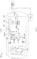
- the circuit architectureis reproduced here as FIG. 3 , and this universal power unit provides electrical power for a variety of embodiments described further below.
- the architecture of this universal power unitincludes a low voltage timer, followed by a preamplifier that feeds a lower step-up voltage transformer.
- the lower step-up voltage transformerin turn feeds a high frequency resonant inductor-capacitor (LC) circuit that is input to an upper step-up voltage transformer.
- the output of the upper step-up voltage transformerprovides the output from the unipolar high voltage power supply.
- LCinductor-capacitor
- FIG. 3also illustrates an exemplary implementation of the unipolar high voltage power supply 310 architecture.
- a timer integrated circuitsuch as a 555 timer 320 provides a low voltage pulsed source with a frequency that is tunable over a frequency range centered at approximately 1 kHz.
- the output of the 555 timer 320is fed into a preamplifier that is formed from a common emitter bipolar transistor 330 whose load is the primary winding of the lower step-up voltage transformer 340.
- the collector voltage of the transistorforms the output voltage that is input into the lower step-up voltage transformer.
- the lower step-up transformerprovides a magnification of the voltage to the secondary windings.
- the output voltage of the lower step-up voltage transformeris forwarded to a series combination of a high voltage rectifier diode 350, a quenching gap 360 and finally to a series LC resonant circuit 370.
- the rectifier diodeconducts, but the quench gap voltage will not have exceeded its breakdown voltage. Accordingly, the quench gap is an open circuit, and therefore the capacitor in the series LC resonant circuit will charge up.
- the capacitorstops charging and begins to discharge. The energy stored in the capacitor is discharged via the tank circuit formed by the series LC connection.
- the inductoralso forms the primary winding of the upper step-up voltage transformer 340.
- the voltage across the inductor of the LC circuitwill resonate at the resonant frequency of the LC circuit 370, and in turn will be further stepped-up at the secondary winding of the upper step-up voltage transformer.
- the resonant frequency of the LC circuit 370can be set to in the high kHz - low MHz range.
- the voltage at the secondary winding of the upper step-up transformeris connected to the output of the power supply unit for delivery to the cold plasma device.
- the typical output voltageis in the 10 - 150 kV voltage range.
- voltage pulses having a frequency in the high kHz - low MHz rangecan be generated with an adjustable repetition frequency in the 1 kHz range.
- the output waveformis shaped similar to the acoustic waveform generated by an impulse such as a bell is struck with a hammer.
- the impulseis provided when the spark gap (or SCR) fires and produces the voltage pulse which causes the resonant circuits in the primary and secondary sides of the transformer to resonate at their specific resonant frequencies.
- the resonant frequencies of the primary and the secondary windingsare different. As a result, the two signals mix and produce the unique 'harmonic' waveform seen in the transformer output.
- the net result of the unipolar high voltage power supplyis the production of a high voltage waveform with a novel "electrical signature," which when combined with a noble gas or other suitable gas, produces a unique harmonic cold plasma that provides advantageous results in wound healing, bacterial removal and other applications.
- the quenching gap 360is a component of the unipolar high voltage power supply 310. It modulates the push/pull of electrical energy between the capacitance banks, with the resulting generation of electrical energy that is rich in harmonic content.
- the quenching gapcan be accomplished in a number of different ways, including a sealed spark gap and an unsealed spark gap.
- the sealed spark gapis not adjustable, while unsealed spark gaps can be adjustable.
- a sealed spark gapcan be realized using, for example, a DECI-ARC 3000 V gas tube from Reynolds Industries, Inc. Adjustable spark gaps provide the opportunity to adjust the output of the unipolar high voltage power supply and the intensity of the cold plasma device to which it is connected.
- a sealed (and therefore non-adjustable) spark gapthereby ensuring a stable plasma intensity.
- a 555 timer 320is used to provide a pulse repetition frequency of approximately 150-600 Hz.
- the unipolar high voltage power supplyproduces a series of spark gap discharge pulses based on the pulse repetition frequency.
- the spark gap discharge pulseshave a very narrow pulse width due to the extremely rapid discharge of capacitive stored energy across the spark gap. Initial assessments of the pulse width of the spark gap discharge pulses indicate that the pulse width is approximately 1 nsec.
- the spark gap discharge pulse traincan be described or modeled as a filtered pulse train.
- a simple resistor-inductor-capacitor (RLC) filtercan be used to model the capacitor, high voltage coil and series resistance of the unipolar high voltage power supply.
- the spark gap discharge pulse traincan be modeled as a simple modeled RLC frequency response centered in the range of around 100 MHz. Based on the pulse repetition frequency of 192 Hz, straightforward signal analysis indicates that there would be approximately 2,000,000 individual harmonic components between DC and 400 MHz.
- a 556 timer or any timer circuitcan be used in place of the 555 timer 320.
- the 556 timerprovides a wider frequency tuning range that results in greater stability and improved cadence of the unipolar high voltage power supply when used in conjunction with the cold plasma device.
- a smart electronics featurecan be added to the high voltage power supply.
- the high voltage power supplycan recognize the type of cold plasma hand piece that is connected to the high voltage power supply, and adjust the power supply output accordingly. For example, with a different hand piece, the output voltage, output resonant frequency or timer frequency can be adjusted to support the particular hand piece being used.
- the smart electronicscan recognize not only the particular hand piece being connected to the power supply, but also one or more of the particular nozzles (tips) being connected at the gas outlet of the hand piece and the composition of gas and the duration of treatment based on the connection at the gas inlet.
- predetermined box settingscan be automatically made by the power supply in response to these sensed configurations.
- the sensing processcan be accomplished by any of the numerous methods by which such configuration data can be obtained.
- the coding of the hand-piece and/or nozzlecan be performed via an ID chip (e.g., a RFID chip), which can be read remotely by the appropriate RFID interrogator installed in the high voltage power supply.
- ID chipe.g., a RFID chip
- RFID interrogatorinstalled in the high voltage power supply.
- Other alternative means of information storageinclude electrically erasable programmable read only memory (EEPROM).
- the configuration datacan include the hand-piece-nozzle configuration, or could also contain information such as safety and other information (such as maximums and minimums) that are set by various regulatory and other authorities.
- the data memorycan indicate the maximum time to which a particular treatment area can be exposed. Where more complex relationships apply to various relevant operating parameters, such information can also be stored in the data memory.
- wired and/or wireless connectivitycan be provided to make the relevant information available to the high voltage power supply.
- the high voltage power supplyresponds automatically by making the appropriate settings, such as low frequency, resonant high frequency, output voltage, gas flow rates and time of operation.
- one cold plasma treatment regimeninvolves the use of 30 seconds of helium gas.
- Other medical treatment regimens for other medical applicationsuse other gas compositions and other gas volumes.
- Use of a gas cartridge having the required volume and gas composition appropriate for the treatment regimenreduces errors in the use, safety and efficacy of cold plasma treatments.
- FIG. 4Aillustrates a gas cartridge 400, for use with an embodiment of the present invention.
- gas cartridge 400is cylindrical in shape, and has a bulbous shape similar to a bottle.
- Gas cartridge 400has a bottle neck 410 at its distal end 420.
- Gas cartridge 400can be manufactured from any suitable material that can contain the gas, such as a metal, heavy duty plastic, and the like.
- Gas cartridge 400can use a threaded connector for connection, or any other suitable connection arrangement, such as quarter-turn connections, half-turn connections and the like.
- Connector 430is located at distal end 420, and is configured to be connected to cold plasma hand-piece.
- gas cartridge 400is not limited to a bulbous (bottle-like) shape, as other shapes are within the scope of the present invention.
- a gas storage compartment 440containing the appropriate quantity (typically under pressure) of the appropriate gas composition for delivery to the cold plasma hand-piece.
- connector 430Prior to being connected, connector 430 maintains a seal that prevents the gas stored in gas storage compartment 440 to leave gas cartridge 400.
- connector 430allows gas stored in gas storage compartment 440 to leave gas cartridge 400.
- a gasketcan be provided in each gas cartridge 400.
- a gasketcan be provided in the mating connector in the cold plasma hand-piece (or in the power supply in other examples not being part of the present invention), with the benefit being a single gasket rather than a gasket required for each gas cartridge 400.
- connector 430has an endcap (or faceseal) 450 placed across the outlet of gas cartridge 400.
- Endcap 450provides the seal across the face of the outlet of gas cartridge 400 to prevent escape of the gas.
- Endcap 450can be manufactured from any suitable material (e.g., metallic material) to maintain the seal in gas cartridge 400.
- mating connector 470 in a cold plasma delivery systemincludes a pin 460 that is typically in the center of mating connector 470. Pin 460 punctures endcap 450 upon the connection of connector 430 and its mating connector.
- the mating connector 470is located in the cold plasma hand-piece, but in alternative examples not being part of the invention, said connector is located in the high voltage power supply of the cold plasma delivery system.
- the cold plasma hand-pieceneeds to incorporate a pressure reducing valve and flow regulator.
- the pressure reducing valve and flow regulatorcan be incorporated into either the high voltage power supply or cold plasma hand-piece.
- connector 430(and its mating connector 470) can be designed to incorporate safety features such that only connectors designed for mating with the cold plasma gun or the power unit of the cold plasma delivery system can make the desired connection.
- gas cartridge 400can contain 2.4 grams of helium gas.
- connector 430is a threaded connector that can connect into a compatible receiving port in the cold plasma delivery system either, in accordance with the present invention in the cold plasma hand-piece or, in accordance with other examples not being part of the present invention, in the high voltage power unit.
- Suitable mating connector locations in the cold plasma hand-piececan be in any number of suitable places, such that the gas can enter the chamber of the hand-piece at a suitable up-stream location consistent with the cold plasma generation process.
- FIGs. 5A and 5Billustrate various embodiments with different locations of the connection between gas cartridge 400 and the cold plasma hand-piece.
- the connection between gas cartridge 400 and cold plasma device 510is located at the base of the hand-grip 520 of the cold plasma hand-piece 510.
- the connection between gas cartridge 400 and cold plasma hand-piece 530is located in the rearward end 540 of the cold plasma hand-piece 530.
- gas cartridge 400can be connected to the high voltage power supply, with the high voltage power supply in turn communicating the gas to the cold plasma hand-piece.
- an optional protective shroud 620can encase the gas cartridge 400 when it is connected to the cold plasma hand-piece 610.
- FIG. 6illustrates an optional protective shroud 620 can be made of any suitable material to prevent damage to a user should gas cartridge 400 explode or disintegrate.
- the gas cartridge of the present inventionis electronically or otherwise coded so that its connection to the cold plasma hand-piece triggers the high voltage power supply to apply the correct voltage, frequency and other related parameters.
- the codingcan be via an ID chip (e.g., a RFID chip) or any other electronic means for storing a particular ID number that can be read by a nearby device such as the power supply.
- cartridgecan be color coded, as well as labeled, so that medical professionals can recognize the appropriate cartridge for the desired treatment.
- This embodimentallows for ease of use, convenience, and portability of the cold plasma hand-piece and cold plasma delivery system. In particular, it provides only enough gas for a given procedure, i.e., is procedure specific. Accordingly, it improves safety of procedure, and the proper use of helium and various other gases (e.g., O 2 , N 2 , water vapor, argon and the like) and mixtures of these gases.
- Disposable gas cartridgeswith an ID chip, ensure the gas or gas mixture is compatible with the plasma medical device and settings are appropriate to further ensure safe operation and therefore the effectiveness of treatment, along with the purity/sterility of the gas. This will also function to make sure the pressure is not too high as to damage the machine, and work to eliminate variability between regions and gas suppliers. Lastly, the ID chipped disposable gas cartridges will ensure strict control of the treatment duration for safety and efficacy.
- the cartridgemay be provided in sterile or non-sterile packaging depending upon its intended use.
- a cartridge mounted in the hand applicator and intended for use in the sterile field of an operating roommight require sterilization and packaging, while a cartridge disposed within the power unit and intended for treatment in an outpatient setting may not require sterile handling and packaging.
- the gasshould be of medical grade, high purity, and sterile.
- the gas cartridgeattached to the high voltage power unit, rather than directly to the applicator.
- Advantages of this embodimentare: (a) reduced safety risk if the cold plasma device is dropped with a full gas cartridge attached; (b) greater ease to incorporate an RFID reader or other sensor into the power supply unit rather than into the hand device; (c) the absence of the attached gas cartridge results in an improved ergonomic balance and feel of the hand device; and (d) potential reduction in manufacture cost of the hand held device as the gas regulation is performed remotely.
- a high pressure cartridgeis connected to the hand piece directly ( FIGs. 5A and 5B )
- a pressure reducing valve and flow regulatormust be incorporated into the plasma hand unit.
- the regulator/flow controlis external and on the tank. If the cartridge resides in the power unit, regulator and pressure reduction can still be accomplished remotely from the hand applicator, per the '631 patent.
- FIG. 7provides a flowchart of an exemplary method 700 to use a gas cartridge with a cold plasma device, according to an embodiment of the present invention.
- a gas cartridgeis provided, the gas cartridge containing a suitable amount of gas, the gas cartridge having a connector that includes a seal to prevent the gas from escaping.
- a gas cartridge 400is configured to couple to cold plasma device 610.
- a cold plasma hand pieceis provided, the cold plasma hand piece having a mating connector to the connector in the gas cartridge, where the mating connector that pierces the seal when the mating connector is connected to the gas cartridge connector.
- a seal 450 in gas cartridge 400is pierced when gas cartridge 400 is connected to cold plasma device 510.
- step 730the gas cartridge is connected to the cold plasma hand piece using the connector and the mating connector.
- gas cartridge 400is connected to cold plasma hand-pieces 510, 530 using connector 430 and a mating connector 470 in cold plasma hand-pieces 510, 530.
- step 740method 700 ends.
- FIG. 8provides a flowchart of a further exemplary method 800 to use a gas cartridge with a cold plasma device, according to an example not being part of the present invention.
- step 810a gas cartridge is provided, the gas cartridge containing a suitable amount of gas, the gas cartridge having a connector that includes a seal to prevent the gas from escaping.
- the gas cartridge 400is configured to couple to a high voltage power supply.
- step 820a cold plasma device and a pulsed high voltage power supply are provided, the high voltage power supply having a mating connector to the connector in the gas cartridge, where the mating connector that pierces the seal when the mating connector is connected to the gas cartridge connector.
- a seal 450 in gas cartridge 400is pierced when gas cartridge 400 is connected to the high voltage power supply.
- step 830the gas cartridge is connected to pulsed high voltage power supply using the connector and the mating connector.
- gaspasses from gas cartridge 400 to the high voltage power supply and forwarded to cold plasma device 510.
- the pulsed high voltage power supplydetermines the type of gas cartridge connected.
- pulsed high voltage power supplydetermines the type of gas cartridge 510 connected. Determination of the type of gas cartridge can be achieved by a keyed physical feature on the cartridge, an RFID tag on the cartridge, an electronic microchip on the cartridge, a bar code on the cartridge, a magnetic tag on the cartridge, or an optically readable tag on the cartridge.
- step 850the pulsed high voltage power supply adjusts one or more of its operating parameters based on the type of connected gas cartridge.
- step 860the pulsed high voltage power supply applies voltage to cold plasma hand piece.
- step 870method 800 ends.
Landscapes
- Health & Medical Sciences (AREA)
- Engineering & Computer Science (AREA)
- Life Sciences & Earth Sciences (AREA)
- Physics & Mathematics (AREA)
- Animal Behavior & Ethology (AREA)
- General Health & Medical Sciences (AREA)
- Public Health (AREA)
- Veterinary Medicine (AREA)
- Plasma & Fusion (AREA)
- Chemical & Material Sciences (AREA)
- Biomedical Technology (AREA)
- Analytical Chemistry (AREA)
- Epidemiology (AREA)
- Hematology (AREA)
- Pulmonology (AREA)
- Anesthesiology (AREA)
- Heart & Thoracic Surgery (AREA)
- Radiology & Medical Imaging (AREA)
- Nuclear Medicine, Radiotherapy & Molecular Imaging (AREA)
- Emergency Medicine (AREA)
- Molecular Biology (AREA)
- Medicinal Chemistry (AREA)
- Spectroscopy & Molecular Physics (AREA)
- Bioinformatics & Cheminformatics (AREA)
- Electromagnetism (AREA)
- Chemical Kinetics & Catalysis (AREA)
- Plasma Technology (AREA)
- Apparatus For Disinfection Or Sterilisation (AREA)
- Physical Or Chemical Processes And Apparatus (AREA)
- Medical Preparation Storing Or Oral Administration Devices (AREA)
- Electrotherapy Devices (AREA)
Description
- The present invention relates to devices and methods for creating cold plasmas, and, more particularly, to such devices that are hand-held and methods for using same.
- Atmospheric pressure hot plasmas are known to exist in nature. For example, lightning is an example of a DC arc (hot) plasma. Many DC arc plasma applications have been achieved in various manufacturing processes, for example, for use in forming surface coatings. Atmospheric pressure cold plasma processes are also known in the art. Most of the at or near atmospheric pressure cold plasma processes are known to utilize positive to negative electrodes in different configurations, which release free electrons in a noble gas medium.
- Devices that use a positive to negative electrode configuration to form a cold plasma from noble gases (helium, argon, etc.) have frequently exhibited electrode degradation and overheating difficulties through continuous device operation. The process conditions for enabling a dense cold plasma electron population without electrode degradation and/or overheating are difficult to achieve.
- Cold plasma devices can be used in a number of different medical treatments relevant to a number of different applications. It is desirable to ensure safe operation and effectiveness of treatment, as well as the purity and sterility of the feed gas.
- Therefore, it would be beneficial to provide a device for producing a cold plasma that overcomes the difficulties inherent in prior known devices.
US 2011/0054454 discloses a surgical instrument for providing an ionized gas to a surgical site including a receptacle for a cylinder of pressurized surgical gas and a frame having a port near the distal end for emitting the surgical gas.US 2009/0012589 discloses a device for generating atmospheric pressure cold plasma inside a hand-held unit, which discharges cold plasma with simultaneously different rf wavelengths and their harmonics.EP 0508402 discloses a unique torch assembly having specific characteristics determinative of the desired operating parameters of the torch assembly.US 2010/0275950 discloses a device and a method for the treatment of surfaces with a plasma produced under atmospheric pressure.EP 1117279 discloses that a torch head fitted to a plasma torch body may be checked for suitability by embedding an identifying element in the head.- A first aspect of the present invention provides a cold plasma delivery system according to claim 1.
- A further aspect of the present invention provides a method according to
claim 10. - Preferred embodiments of the present invention are defined in the dependent claims.
FIGs. 1A and1B are cutaway views of the hand-held atmospheric harmonic cold plasma device, in accordance with embodiments of the present invention.FIGs. 2A and2B illustrate an embodiment of the cold plasma device without magnets, in accordance with embodiments of the present invention.FIG. 3 is an exemplary circuit diagram of the power supply of a cold plasma device, for use with embodiments of the present invention.FIGs. 4A and 4B illustrate a gas cartridge for use with a cold plasma device, in accordance with embodiments of the present invention.FIGs. 5A and5B illustrate different connections of a gas cartridge within a cold plasma delivery system, in accordance with an embodiment of the present invention.FIG. 6 illustrates a safety shroud that encloses an attached gas cartridge within a cold plasma delivery system, in accordance with an embodiment of the present invention.FIG. 7 illustrates a method of use of a gas cartridge within a cold plasma hand-piece, in accordance with an embodiment of the present invention.FIG. 8 illustrates a method of use of a gas cartridge that connects to the high voltage power supply, in accordance with an example not being part of the present invention.- Cold temperature atmospheric pressure plasmas have attracted a great deal of enthusiasm and interest by virtue of their provision of plasmas at relatively low gas temperatures. The provision of a plasma at such a temperature is of interest to a variety of applications, including wound healing, anti-bacterial processes, various other medical therapies and sterilization. The optimal treatment regime for each of these applications may include a different gas, gas flow rate, and other system settings.
- To achieve a cold plasma, a cold plasma device typically takes as input a source of appropriate gas and a source of high voltage electrical energy, and outputs a plasma plume.
FIG. 1A illustrates such a cold plasma device. Previous work by the inventors in this research area has been described inU.S. Provisional Patent Application No. 60/913,369 ,U.S. Non-provisional Application No. 12/038,159 (that has issued asU.S. Patent No. 7,633,231 ) and the subsequent continuation applications (collectively "the '369 application family"). The following paragraphs discuss further the subject matter from this application family further, as well as additional developments in this field. - The '369 application family describes a cold plasma device that is supplied with helium gas, connected to a high voltage energy source, and which results in the output of a cold plasma. The temperature of the cold plasma is approximately 18.33- 48.88 °C (65-120 degrees F) (preferably 18.33-37.22 °C, corresponding to 65-99 degrees F), and details of the electrode, induction grid and magnet structures are described. The voltage waveforms in the device are illustrated at a typical operating point in '369 application family.
- In a further embodiment to that described in the '369 application, plasma is generated using an apparatus without magnets, as illustrated in
FIGs. 2A and2B . In this magnet-free environment, the plasma generated by the action of theelectrodes 12 is carried with the fluid flow downstream towards thenozzle 68.FIG. 2A illustrates a magnet-free embodiment in which no induction grid is used.FIG. 2B illustrates a magnet-free embodiment in whichinduction grid 66 is used.FIG. 1B illustrates the same embodiment as illustratedFIG. 2B , but from a different view. Although these embodiments illustrate the cold plasma is generated fromelectrode 12, other embodiments do not power the cold plasmadevice using electrode 12, but instead power the cold plasma device usinginduction grid 66. - In both a magnet and a magnet-free embodiment, the
inductance grid 66 is optional. Wheninductance grid 66 is present, it provides ionization energy to the gas as the gas passes by. Thus, although theinductance grid 66 is optional, its presence enriches the resulting plasma. - As noted above, the
inductance grid 66 is optional. When absent, the plasma will nevertheless transit the cold plasma device and exit at thenozzle 68, although in this case, there will be no additional ionization energy supplied to the gas as it transits the latter stage of the cold plasma device. - As noted with respect to other embodiments, magnetic fields can be used in conjunction with the production of cold plasmas. Where present, magnetic fields act, at least at some level, to constrain the plasma and to guide it through the device. In general, electrically charged particles tend to move along magnetic field lines in spiral trajectories. As noted elsewhere, other embodiments can comprise magnets configured and arranged to produce various magnetic field configurations to suit various design considerations. For example, in one embodiment as described in the previously filed '369 application family, a pair of magnets may be configured to give rise to magnetic fields with opposing directions that act to confine the plasma near the inductance grid.
- The '369 application family also illustrates an embodiment of the unipolar high voltage power supply architecture and components used therein. The circuit architecture is reproduced here as
FIG. 3 , and this universal power unit provides electrical power for a variety of embodiments described further below. The architecture of this universal power unit includes a low voltage timer, followed by a preamplifier that feeds a lower step-up voltage transformer. The lower step-up voltage transformer in turn feeds a high frequency resonant inductor-capacitor (LC) circuit that is input to an upper step-up voltage transformer. The output of the upper step-up voltage transformer provides the output from the unipolar high voltage power supply. FIG. 3 also illustrates an exemplary implementation of the unipolar highvoltage power supply 310 architecture. In this implementation, a timer integrated circuit such as a 555timer 320 provides a low voltage pulsed source with a frequency that is tunable over a frequency range centered at approximately 1 kHz. The output of the 555timer 320 is fed into a preamplifier that is formed from a common emitterbipolar transistor 330 whose load is the primary winding of the lower step-upvoltage transformer 340. The collector voltage of the transistor forms the output voltage that is input into the lower step-up voltage transformer. The lower step-up transformer provides a magnification of the voltage to the secondary windings. In turn, the output voltage of the lower step-up voltage transformer is forwarded to a series combination of a highvoltage rectifier diode 350, aquenching gap 360 and finally to a series LCresonant circuit 370. As the voltage waveform rises, the rectifier diode conducts, but the quench gap voltage will not have exceeded its breakdown voltage. Accordingly, the quench gap is an open circuit, and therefore the capacitor in the series LC resonant circuit will charge up. Eventually, as the input voltage waveform increases, the voltage across the quench gap exceeds its breakdown voltage, and it arcs over and becomes a short circuit. At this time, the capacitor stops charging and begins to discharge. The energy stored in the capacitor is discharged via the tank circuit formed by the series LC connection.- Continuing to refer to
FIG. 3 , the inductor also forms the primary winding of the upper step-upvoltage transformer 340. Thus, the voltage across the inductor of the LC circuit will resonate at the resonant frequency of theLC circuit 370, and in turn will be further stepped-up at the secondary winding of the upper step-up voltage transformer. The resonant frequency of theLC circuit 370 can be set to in the high kHz - low MHz range. The voltage at the secondary winding of the upper step-up transformer is connected to the output of the power supply unit for delivery to the cold plasma device. The typical output voltage is in the 10 - 150 kV voltage range. Thus, voltage pulses having a frequency in the high kHz - low MHz range can be generated with an adjustable repetition frequency in the 1 kHz range. The output waveform is shaped similar to the acoustic waveform generated by an impulse such as a bell is struck with a hammer. Here, the impulse is provided when the spark gap (or SCR) fires and produces the voltage pulse which causes the resonant circuits in the primary and secondary sides of the transformer to resonate at their specific resonant frequencies. The resonant frequencies of the primary and the secondary windings are different. As a result, the two signals mix and produce the unique 'harmonic' waveform seen in the transformer output. The net result of the unipolar high voltage power supply is the production of a high voltage waveform with a novel "electrical signature," which when combined with a noble gas or other suitable gas, produces a unique harmonic cold plasma that provides advantageous results in wound healing, bacterial removal and other applications. - The
quenching gap 360 is a component of the unipolar highvoltage power supply 310. It modulates the push/pull of electrical energy between the capacitance banks, with the resulting generation of electrical energy that is rich in harmonic content. The quenching gap can be accomplished in a number of different ways, including a sealed spark gap and an unsealed spark gap. The sealed spark gap is not adjustable, while unsealed spark gaps can be adjustable. A sealed spark gap can be realized using, for example, a DECI-ARC 3000 V gas tube from Reynolds Industries, Inc. Adjustable spark gaps provide the opportunity to adjust the output of the unipolar high voltage power supply and the intensity of the cold plasma device to which it is connected. In a further embodiment of the present invention that incorporates a sealed (and therefore non-adjustable) spark gap, thereby ensuring a stable plasma intensity. - In an exemplary embodiment of the unipolar high voltage power supply, a 555
timer 320 is used to provide a pulse repetition frequency of approximately 150-600 Hz. As discussed above, the unipolar high voltage power supply produces a series of spark gap discharge pulses based on the pulse repetition frequency. The spark gap discharge pulses have a very narrow pulse width due to the extremely rapid discharge of capacitive stored energy across the spark gap. Initial assessments of the pulse width of the spark gap discharge pulses indicate that the pulse width is approximately 1 nsec. The spark gap discharge pulse train can be described or modeled as a filtered pulse train. In particular, a simple resistor-inductor-capacitor (RLC) filter can be used to model the capacitor, high voltage coil and series resistance of the unipolar high voltage power supply. In one embodiment of the invention, the spark gap discharge pulse train can be modeled as a simple modeled RLC frequency response centered in the range of around 100 MHz. Based on the pulse repetition frequency of 192 Hz, straightforward signal analysis indicates that there would be approximately 2,000,000 individual harmonic components between DC and 400 MHz. - In another embodiment of the unipolar high voltage power supply described above, a 556 timer or any timer circuit can be used in place of the 555
timer 320. In comparison with the 555 timer, the 556 timer provides a wider frequency tuning range that results in greater stability and improved cadence of the unipolar high voltage power supply when used in conjunction with the cold plasma device. - In a further embodiment of the high voltage power supply, a smart electronics feature can be added to the high voltage power supply. With this feature added, the high voltage power supply can recognize the type of cold plasma hand piece that is connected to the high voltage power supply, and adjust the power supply output accordingly. For example, with a different hand piece, the output voltage, output resonant frequency or timer frequency can be adjusted to support the particular hand piece being used. In a further embodiment, the smart electronics can recognize not only the particular hand piece being connected to the power supply, but also one or more of the particular nozzles (tips) being connected at the gas outlet of the hand piece and the composition of gas and the duration of treatment based on the connection at the gas inlet. Based on being able to sense the nozzle-hand-piece combination, predetermined box settings can be automatically made by the power supply in response to these sensed configurations. The sensing process can be accomplished by any of the numerous methods by which such configuration data can be obtained. For example, the coding of the hand-piece and/or nozzle can be performed via an ID chip (e.g., a RFID chip), which can be read remotely by the appropriate RFID interrogator installed in the high voltage power supply. Other alternative means of information storage include electrically erasable programmable read only memory (EEPROM). Other alternatives for the sensing include the use of a simple mechanical-electrical connection such as pin connectors or the use of printed metal stripes (similar to a barcode) on the surface of the nozzle or gas cartridge (to be discussed further below) that physically makes the desired connection. The configuration data can include the hand-piece-nozzle configuration, or could also contain information such as safety and other information (such as maximums and minimums) that are set by various regulatory and other authorities. For example, the data memory can indicate the maximum time to which a particular treatment area can be exposed. Where more complex relationships apply to various relevant operating parameters, such information can also be stored in the data memory. In addition to remote sensing of the data memory, wired and/or wireless connectivity can be provided to make the relevant information available to the high voltage power supply. In response to the received data, the high voltage power supply responds automatically by making the appropriate settings, such as low frequency, resonant high frequency, output voltage, gas flow rates and time of operation.
- Evaluations of the use of cold plasma treatments has revealed that such treatments use a particular treatment time, using a particular amount of gas having a particular composition of gas, with a particular electrical setting in the hand-piece. Conventional wisdom had suggested that length of cold plasma treatment could be arbitrary, and that a medical professional might have had considerable discretion in selecting the amount of time for each cold plasma treatment. However, studies have revealed that, contrary to the conventional wisdom, a particular treatment time using a particular amount of gas is effective for many applications. Such a revelation on the relevance of a particular amount of gas provides the opportunity for the use of gas cartridges of various sizes that are relevant to particular treatments.
- As an example, for a sterilization and accelerated healing of a laceration, one cold plasma treatment regimen involves the use of 30 seconds of helium gas. Other medical treatment regimens for other medical applications use other gas compositions and other gas volumes. Use of a gas cartridge having the required volume and gas composition appropriate for the treatment regimen reduces errors in the use, safety and efficacy of cold plasma treatments.
FIG. 4A illustrates agas cartridge 400, for use with an embodiment of the present invention. In this embodiment,gas cartridge 400 is cylindrical in shape, and has a bulbous shape similar to a bottle.Gas cartridge 400 has abottle neck 410 at itsdistal end 420.Gas cartridge 400 can be manufactured from any suitable material that can contain the gas, such as a metal, heavy duty plastic, and the like.Gas cartridge 400 can use a threaded connector for connection, or any other suitable connection arrangement, such as quarter-turn connections, half-turn connections and the like.Connector 430 is located atdistal end 420, and is configured to be connected to cold plasma hand-piece. In other embodiments of the present invention,gas cartridge 400 is not limited to a bulbous (bottle-like) shape, as other shapes are within the scope of the present invention. Internal togas cartridge 400 is agas storage compartment 440 containing the appropriate quantity (typically under pressure) of the appropriate gas composition for delivery to the cold plasma hand-piece. Prior to being connected,connector 430 maintains a seal that prevents the gas stored ingas storage compartment 440 to leavegas cartridge 400. When connected,connector 430 allows gas stored ingas storage compartment 440 to leavegas cartridge 400. To prevent leakage of gas in the connection, a gasket can be provided in eachgas cartridge 400. Alternatively, a gasket can be provided in the mating connector in the cold plasma hand-piece (or in the power supply in other examples not being part of the present invention), with the benefit being a single gasket rather than a gasket required for eachgas cartridge 400. In an embodiment,connector 430 has an endcap (or faceseal) 450 placed across the outlet ofgas cartridge 400.Endcap 450 provides the seal across the face of the outlet ofgas cartridge 400 to prevent escape of the gas.Endcap 450 can be manufactured from any suitable material (e.g., metallic material) to maintain the seal ingas cartridge 400.- With further reference to
FIG. 4B ,mating connector 470 in a cold plasma delivery system includes apin 460 that is typically in the center ofmating connector 470.Pin 460 punctures endcap 450 upon the connection ofconnector 430 and its mating connector. In the present invention, themating connector 470 is located in the cold plasma hand-piece, but in alternative examples not being part of the invention, said connector is located in the high voltage power supply of the cold plasma delivery system. When the stored gas ingas cartridge 400 is under pressure, the cold plasma hand-piece needs to incorporate a pressure reducing valve and flow regulator. In examples not being part of the present invention wheregas cartridge 400 connects to the high voltage power supply, the pressure reducing valve and flow regulator can be incorporated into either the high voltage power supply or cold plasma hand-piece. In most cases, the pressure reducing valve and flow regulator would be incorporated into a cold plasma hand-piece. In certain embodiments of the present invention, connector 430 (and its mating connector 470) can be designed to incorporate safety features such that only connectors designed for mating with the cold plasma gun or the power unit of the cold plasma delivery system can make the desired connection. - In an exemplary embodiment,
gas cartridge 400 can contain 2.4 grams of helium gas. Ingas cartridge 400,connector 430 is a threaded connector that can connect into a compatible receiving port in the cold plasma delivery system either, in accordance with the present invention in the cold plasma hand-piece or, in accordance with other examples not being part of the present invention, in the high voltage power unit. - Suitable mating connector locations in the cold plasma hand-piece can be in any number of suitable places, such that the gas can enter the chamber of the hand-piece at a suitable up-stream location consistent with the cold plasma generation process.
FIGs. 5A and5B illustrate various embodiments with different locations of the connection betweengas cartridge 400 and the cold plasma hand-piece. In one exemplary embodiment (illustrated inFIG. 5A ), the connection betweengas cartridge 400 andcold plasma device 510 is located at the base of the hand-grip 520 of the cold plasma hand-piece 510. In an alternative exemplary embodiment (illustrated inFIG. 5B ), the connection betweengas cartridge 400 and cold plasma hand-piece 530 is located in therearward end 540 of the cold plasma hand-piece 530. In both embodiments, the gas is routed internally within the cold plasma hand-piece to its gas compartment. In a still further example not being part of the present invention not illustrated),gas cartridge 400 can be connected to the high voltage power supply, with the high voltage power supply in turn communicating the gas to the cold plasma hand-piece. - For embodiments where
gas cartridge 400 is connected to cold plasma hand-piece 610, an optionalprotective shroud 620 can encase thegas cartridge 400 when it is connected to the cold plasma hand-piece 610.FIG. 6 illustrates an optionalprotective shroud 620 can be made of any suitable material to prevent damage to a user shouldgas cartridge 400 explode or disintegrate. - In addition, the gas cartridge of the present invention is electronically or otherwise coded so that its connection to the cold plasma hand-piece triggers the high voltage power supply to apply the correct voltage, frequency and other related parameters. The coding can be via an ID chip (e.g., a RFID chip) or any other electronic means for storing a particular ID number that can be read by a nearby device such as the power supply. In addition, for ease of use, cartridge can be color coded, as well as labeled, so that medical professionals can recognize the appropriate cartridge for the desired treatment. This embodiment allows for ease of use, convenience, and portability of the cold plasma hand-piece and cold plasma delivery system. In particular, it provides only enough gas for a given procedure, i.e., is procedure specific. Accordingly, it improves safety of procedure, and the proper use of helium and various other gases (e.g., O2, N2, water vapor, argon and the like) and mixtures of these gases.
- Disposable gas cartridges, with an ID chip, ensure the gas or gas mixture is compatible with the plasma medical device and settings are appropriate to further ensure safe operation and therefore the effectiveness of treatment, along with the purity/sterility of the gas. This will also function to make sure the pressure is not too high as to damage the machine, and work to eliminate variability between regions and gas suppliers. Lastly, the ID chipped disposable gas cartridges will ensure strict control of the treatment duration for safety and efficacy.
- When treating open wounds with an instrument such as cold plasma, it is important to ensure that no new pathogens are introduced to the wound and that pathogens are not spread from patient to patient. Therefore, it is desirable to have a, prepackaged, and easily exchangeable gas cartridge that can be disposed of and replaced between each use. Further, different wound types may warrant different gas compositions or volumes to supply and/or modify the plasma plume for a patient-specific approach to plasma wound therapy. The following additional embodiments seek to meet these needs with disposable gas cartridges capable of generating a unique and varied plasma plume of compositional make-up providing suitable reactive species of gas and/or discrete treatment duration.
- The cartridge may be provided in sterile or non-sterile packaging depending upon its intended use. For example, a cartridge mounted in the hand applicator and intended for use in the sterile field of an operating room might require sterilization and packaging, while a cartridge disposed within the power unit and intended for treatment in an outpatient setting may not require sterile handling and packaging. In either case, the gas should be of medical grade, high purity, and sterile.
- In another example not being part of the present invention (not illustrated), it may be more desirable to have the gas cartridge attached to the high voltage power unit, rather than directly to the applicator. Advantages of this embodiment are: (a) reduced safety risk if the cold plasma device is dropped with a full gas cartridge attached; (b) greater ease to incorporate an RFID reader or other sensor into the power supply unit rather than into the hand device; (c) the absence of the attached gas cartridge results in an improved ergonomic balance and feel of the hand device; and (d) potential reduction in manufacture cost of the hand held device as the gas regulation is performed remotely. When a high pressure cartridge is connected to the hand piece directly (
FIGs. 5A and5B ), a pressure reducing valve and flow regulator must be incorporated into the plasma hand unit. In '631 patent, the regulator/flow control is external and on the tank. If the cartridge resides in the power unit, regulator and pressure reduction can still be accomplished remotely from the hand applicator, per the '631 patent. FIG. 7 provides a flowchart of anexemplary method 700 to use a gas cartridge with a cold plasma device, according to an embodiment of the present invention.- The process begins at step 710. In step 710, a gas cartridge is provided, the gas cartridge containing a suitable amount of gas, the gas cartridge having a connector that includes a seal to prevent the gas from escaping. In an embodiment, a
gas cartridge 400 is configured to couple tocold plasma device 610. - In
step 720, a cold plasma hand piece is provided, the cold plasma hand piece having a mating connector to the connector in the gas cartridge, where the mating connector that pierces the seal when the mating connector is connected to the gas cartridge connector. In an exemplary embodiment, aseal 450 ingas cartridge 400 is pierced whengas cartridge 400 is connected tocold plasma device 510. - In
step 730, the gas cartridge is connected to the cold plasma hand piece using the connector and the mating connector. In an exemplary embodiment,gas cartridge 400 is connected to cold plasma hand-pieces connector 430 and amating connector 470 in cold plasma hand-pieces - At
step 740,method 700 ends. FIG. 8 provides a flowchart of a furtherexemplary method 800 to use a gas cartridge with a cold plasma device, according to an example not being part of the present invention.- The process begins at step 810. In step 810, a gas cartridge is provided, the gas cartridge containing a suitable amount of gas, the gas cartridge having a connector that includes a seal to prevent the gas from escaping. In this example the
gas cartridge 400 is configured to couple to a high voltage power supply. - In
step 820, a cold plasma device and a pulsed high voltage power supply are provided, the high voltage power supply having a mating connector to the connector in the gas cartridge, where the mating connector that pierces the seal when the mating connector is connected to the gas cartridge connector. In an exemplary embodiment, aseal 450 ingas cartridge 400 is pierced whengas cartridge 400 is connected to the high voltage power supply. - In
step 830, the gas cartridge is connected to pulsed high voltage power supply using the connector and the mating connector. In an exemplary embodiment, gas passes fromgas cartridge 400 to the high voltage power supply and forwarded tocold plasma device 510. - In
step 840, the pulsed high voltage power supply determines the type of gas cartridge connected. In an exemplary embodiment, pulsed high voltage power supply determines the type ofgas cartridge 510 connected. Determination of the type of gas cartridge can be achieved by a keyed physical feature on the cartridge, an RFID tag on the cartridge, an electronic microchip on the cartridge, a bar code on the cartridge, a magnetic tag on the cartridge, or an optically readable tag on the cartridge. - In
step 850, the pulsed high voltage power supply adjusts one or more of its operating parameters based on the type of connected gas cartridge. - In
step 860, the pulsed high voltage power supply applies voltage to cold plasma hand piece. - In
step 870,method 800 ends. - It is to be appreciated that this description, and not the abstract, is intended to be used to interpret the claims. The abstract may set forth one or more but not all exemplary embodiments of the present invention as contemplated by the inventor(s), and thus, is not intended to limit the present invention and the appended claims in any way.
- The present invention has been described above with the aid of functional building blocks illustrating the implementation of specified functions and relationships thereof. The boundaries of these functional building blocks have been arbitrarily defined herein for the convenience of the description. Alternate boundaries can be defined so long as the specified functions and relationships thereof are appropriately performed.
- The foregoing description of the specific embodiments will so fully reveal the general nature of the invention that others can, by applying knowledge within the skill of the art, readily modify and/or adapt for various applications such specific embodiments, without undue experimentation, without departing from the extension of the present invention, said extension being determined by the appended claims.
Claims (13)
- A cold plasma delivery system (10), comprising:a cold plasma hand piece device (610), a high voltage power supply (300), and a gas cartridge (400);the gas cartridge (400) having an outlet with a connector (430) for connecting to said cold plasma hand piece device, said connector (430) for having a seal across the outlet configured to be broken upon connection with the cold plasma hand piece device, the gas cartridge (400) having a storage compartment configured to store a quantity of gas sufficient for a specific medical process;the cold plasma hand piece device (610) having a mating connector (470), and further comprising:a nozzle (20; 68);a housing (15) having a high voltage electrical inlet port and a gas compartment (22), the gas compartment (22) having a gas inlet port (25) and a gas outlet port connected to the nozzle;an electrode (12) disposed within the gas compartment (22), wherein the electrode (12) is coupled to the high voltage electrical inlet port;wherein the high voltage power supply (300) is coupled to the high voltage electrical inlet port,wherein the cold plasma hand piece device is configured to connect with the connector (430) of the gas cartridge (400) through the mating connector (470), said mating connector (470) having a pin (460) for breaking said seal; andcharacterised in thatthe cartridge (400) has a coding, wherein the connection between the cold plasma hand piece device (610) with the gas cartridge (400) triggers the high voltage power supply (300) to apply a predetermined voltage, frequency and other related parameters thereof in response to the sensed coding of gas cartridge by said high voltage power supply.
- The cold plasma delivery system (10) of claim 1, wherein the mating connector (470) is located within a hand-grip (520) of the cold plasma hand piece device (610) or located within a rearward end (540) of the cold plasma hand piece device.
- The cold plasma delivery system (10) of claim 2, wherein the mating connector (470) is located within the rearward end (540) of the cold plasma hand piece device, the cold plasma hand piece device further comprising: a shroud (620) attached to the housing (15), the shroud (600) enclosing the gas cartridge (400) to reduce safety risk associated with a dropping of the cold plasma hand piece device.
- The cold plasma delivery system (10) of claim 1, wherein the seal is a metallic endcap (450).
- The cold plasma delivery system (10) of claim 1, wherein the seal is configured to be broken by the pin (460) associated with the cold plasma hand piece device (10).
- The cold plasma delivery system (10) of claim 1, wherein the gas cartridge (400) includes at least one of an RFID tag, an electronic microchip, an EEPROM, a bar code, a magnetic tag, and an optically readable tag to indicate the coding of gas cartridge (400), and the high voltage power supply (300) is configured to sense the coding of gas cartridge (400) using a sensor associated with the at least one of an RFID tag, an electronic microchip, an EEPROM, a bar code, a magnetic tag, and an optically readable tag.
- The cold plasma delivery system (10) of claim 1, further comprising: a portable battery coupled to the high voltage power supply (300), the high voltage power supply (300) being configured to be powered by energy from the portable battery.
- The cold plasma delivery system (10) of claim 1, wherein the high voltage power supply is configured to adjust its operating parameters in response to the sensed coding of gas cartridge (400), wherein the operating parameters that can be adjusted include one or more of voltage, frequency, gas flow rate, gas pressure and treatment duration.
- The cold plasma delivery system (10) of claim 1, wherein the cold plasma delivery system (10) is adapted to sense a type of the nozzle (20) using at least one of an RFID chip, an erasable programmable read only memory (EEPROM), a pin connector, or printed metal stripes associated with the nozzle (20), and wherein the high voltage power supply (300) is further configured to adjust the operating parameters of the cold plasma delivery system (10) in response to the sensed type of the nozzle (20).
- A method (700) to use a gas cartridge (400) with a cold plasma hand piece device (610), said method comprising:providing (710) a gas cartridge (400), the gas cartridge (400) containing a suitable amount of gas for a specific medical process, the gas cartridge having a connector (430) that includes a seal to prevent the gas from escaping;providing (720) a cold plasma hand piece device (610) having a mating connector (470) with a pin (460) the cold plasma hand piece device having a gas outlet port configured for coupling to a nozzle (20; 68) of said cold plasma hand piece device;connecting (730) the gas cartridge (400) to the cold plasma hand piece device (300) using the connector (430) and the mating connector (470) wherein upon connection the pin pierces the seal of the gas cartridge and the cold plasma hand piece device receives gas from the gas cartridge;providing a high voltage power supply (300);the methodcharacterised bysensing, by the high voltage power supply (300), a coding of gas cartridge (400); andin response to this sensing, triggering, by the connection between the cold plasma hand piece device (610) and the gas cartridge (400), the high voltage power supply (300) to apply a predetermined voltage, frequency and other related parameters thereof.
- The method of claim 10, wherein the sensing the coding of gas cartridge (400) includes using an RFID tag on the cartridge (400), an electronic microchip on the cartridge (400), EEPROM on the cartridge (400), a bar code on the cartridge (400), a magnetic tag on the cartridge (400), and an optically readable tag on the cartridge (400).
- The method of claim 10, wherein the applying the voltage, frequency and related parameters thereof in response to the sensed coding of gas cartridge (400) comprises adjusting at least one of pulse frequency, resonance frequency, output voltage and treatment duration.
- The method of claim 10, further comprising:sensing a type of the nozzle (20) using at least one of an RFID chip, an erasable programmable read only memory (EEPROM), a pin connector, or printed metal stripes associated with the nozzle (20); andadjusting one or more operating parameters of the cold plasma delivery system (10) in response to sensing the type of the nozzle (20).
Applications Claiming Priority (2)
| Application Number | Priority Date | Filing Date | Title |
|---|---|---|---|
| US201161535250P | 2011-09-15 | 2011-09-15 | |
| PCT/US2012/055571WO2013052261A2 (en) | 2011-09-15 | 2012-09-14 | Harmonic cold plasma devices and associated methods |
Publications (3)
| Publication Number | Publication Date |
|---|---|
| EP2758979A2 EP2758979A2 (en) | 2014-07-30 |
| EP2758979A4 EP2758979A4 (en) | 2015-02-11 |
| EP2758979B1true EP2758979B1 (en) | 2020-11-11 |
Family
ID=47879451
Family Applications (9)
| Application Number | Title | Priority Date | Filing Date |
|---|---|---|---|
| EP12831962.1AActiveEP2756515B1 (en) | 2011-09-15 | 2012-09-14 | Cold plasma treatment device and associated method |
| EP12838901.2AActiveEP2758979B1 (en) | 2011-09-15 | 2012-09-14 | Cold plasma delivery system and associated method |
| EP12831964.7AActiveEP2756516B1 (en) | 2011-09-15 | 2012-09-14 | Cold plasma treatment devices and associated methods |
| EP12832476.1AActiveEP2756740B1 (en) | 2011-09-15 | 2012-09-14 | Cold plasma treatment devices and associated methods |
| EP12830964.8AActiveEP2756514B1 (en) | 2011-09-15 | 2012-09-14 | Cold plasma treatment devices and associated methods |
| EP12831536.3AActiveEP2755716B1 (en) | 2011-09-15 | 2012-09-14 | Unipolar cold plasma device and associated method |
| EP12832526.3AActiveEP2756517B1 (en) | 2011-09-15 | 2012-09-14 | Cold plasma treatment devices |
| EP12832065.2AActiveEP2756739B1 (en) | 2011-09-15 | 2012-09-14 | Cold plasma sterilization devices and associated methods |
| EP14195019.6AActiveEP2854268B1 (en) | 2011-09-15 | 2012-09-14 | Cold plasma treatment devices and associated methods |
Family Applications Before (1)
| Application Number | Title | Priority Date | Filing Date |
|---|---|---|---|
| EP12831962.1AActiveEP2756515B1 (en) | 2011-09-15 | 2012-09-14 | Cold plasma treatment device and associated method |
Family Applications After (7)
| Application Number | Title | Priority Date | Filing Date |
|---|---|---|---|
| EP12831964.7AActiveEP2756516B1 (en) | 2011-09-15 | 2012-09-14 | Cold plasma treatment devices and associated methods |
| EP12832476.1AActiveEP2756740B1 (en) | 2011-09-15 | 2012-09-14 | Cold plasma treatment devices and associated methods |
| EP12830964.8AActiveEP2756514B1 (en) | 2011-09-15 | 2012-09-14 | Cold plasma treatment devices and associated methods |
| EP12831536.3AActiveEP2755716B1 (en) | 2011-09-15 | 2012-09-14 | Unipolar cold plasma device and associated method |
| EP12832526.3AActiveEP2756517B1 (en) | 2011-09-15 | 2012-09-14 | Cold plasma treatment devices |
| EP12832065.2AActiveEP2756739B1 (en) | 2011-09-15 | 2012-09-14 | Cold plasma sterilization devices and associated methods |
| EP14195019.6AActiveEP2854268B1 (en) | 2011-09-15 | 2012-09-14 | Cold plasma treatment devices and associated methods |
Country Status (3)
| Country | Link |
|---|---|
| US (13) | US9257264B2 (en) |
| EP (9) | EP2756515B1 (en) |
| WO (8) | WO2013040473A1 (en) |
Families Citing this family (116)
| Publication number | Priority date | Publication date | Assignee | Title |
|---|---|---|---|---|
| US7633231B2 (en)* | 2007-04-23 | 2009-12-15 | Cold Plasma Medical Technologies, Inc. | Harmonic cold plasma device and associated methods |
| US10039927B2 (en)* | 2007-04-23 | 2018-08-07 | Plasmology4, Inc. | Cold plasma treatment devices and associated methods |
| US9257264B2 (en)* | 2007-04-23 | 2016-02-09 | Plasmology4, Inc. | Harmonic cold plasma devices and associated methods |
| US9656095B2 (en) | 2007-04-23 | 2017-05-23 | Plasmology4, Inc. | Harmonic cold plasma devices and associated methods |
| US8632534B2 (en) | 2009-04-03 | 2014-01-21 | Angiodynamics, Inc. | Irreversible electroporation (IRE) for congestive obstructive pulmonary disease (COPD) |
| WO2010138919A2 (en) | 2009-05-28 | 2010-12-02 | Angiodynamics, Inc. | System and method for synchronizing energy delivery to the cardiac rhythm |
| US9895189B2 (en) | 2009-06-19 | 2018-02-20 | Angiodynamics, Inc. | Methods of sterilization and treating infection using irreversible electroporation |
| DE102009028462A1 (en)* | 2009-08-11 | 2011-03-24 | Leibniz-Institut für Plasmaforschung und Technologie e.V. | Apparatus and method for the treatment of living cells by means of a plasma |
| US10455682B2 (en) | 2012-04-04 | 2019-10-22 | Hypertherm, Inc. | Optimization and control of material processing using a thermal processing torch |
| US10486260B2 (en)* | 2012-04-04 | 2019-11-26 | Hypertherm, Inc. | Systems, methods, and devices for transmitting information to thermal processing systems |
| US9481050B2 (en) | 2013-07-24 | 2016-11-01 | Hypertherm, Inc. | Plasma arc cutting system and persona selection process |
| US9782852B2 (en)* | 2010-07-16 | 2017-10-10 | Hypertherm, Inc. | Plasma torch with LCD display with settings adjustment and fault diagnosis |
| US20140069895A1 (en)* | 2012-04-04 | 2014-03-13 | Hypertherm, Inc. | Automated cartridge detection for a plasma arc cutting system |
| EP2627274B1 (en) | 2010-10-13 | 2022-12-14 | AngioDynamics, Inc. | System for electrically ablating tissue of a patient |
| US9220162B2 (en)* | 2011-03-09 | 2015-12-22 | Samsung Electronics Co., Ltd. | Plasma generating apparatus and plasma generating method |
| US9078665B2 (en) | 2011-09-28 | 2015-07-14 | Angiodynamics, Inc. | Multiple treatment zone ablation probe |
| US9414881B2 (en) | 2012-02-08 | 2016-08-16 | Angiodynamics, Inc. | System and method for increasing a target zone for electrical ablation |
| US9672460B2 (en) | 2012-04-04 | 2017-06-06 | Hypertherm, Inc. | Configuring signal devices in thermal processing systems |
| US11783138B2 (en)* | 2012-04-04 | 2023-10-10 | Hypertherm, Inc. | Configuring signal devices in thermal processing systems |
| US20150332071A1 (en) | 2012-04-04 | 2015-11-19 | Hypertherm, Inc. | Configuring Signal Devices in Thermal Processing Systems |
| US9395715B2 (en) | 2012-04-04 | 2016-07-19 | Hypertherm, Inc. | Identifying components in a material processing system |
| US9737954B2 (en) | 2012-04-04 | 2017-08-22 | Hypertherm, Inc. | Automatically sensing consumable components in thermal processing systems |
| RU2015109276A (en) | 2012-09-14 | 2016-11-10 | Колд Плазма Медикал Текнолоджиз, Инк. | THERAPEUTIC APPLICATION OF COLD PLASMA |
| EP2931067B1 (en)* | 2012-12-11 | 2018-02-07 | Plasmology4, Inc. | Method and apparatus for cold plasma food contact surface sanitation |
| WO2014106258A1 (en) | 2012-12-31 | 2014-07-03 | Cold Plasma Medical Technologies, Inc. | Cold plasma electroporation of medication and associated methods |
| IL226105A (en)* | 2013-01-16 | 2014-05-28 | Orteron T O Ltd | System and method for generating modified plasma |
| US10266802B2 (en)* | 2013-01-16 | 2019-04-23 | Orteron (T.O) Ltd. | Method for controlling biological processes in microorganisms |
| DE102013100617B4 (en)* | 2013-01-22 | 2016-08-25 | Epcos Ag | Device for generating a plasma and handheld device with the device |
| FR3007273B1 (en)* | 2013-06-21 | 2015-07-31 | Oreal | COSMETIC USE OF COLD PLASMA |
| US9643273B2 (en) | 2013-10-14 | 2017-05-09 | Hypertherm, Inc. | Systems and methods for configuring a cutting or welding delivery device |
| WO2015059702A1 (en)* | 2013-10-24 | 2015-04-30 | Ionmed Ltd. | Cold plasma treatment |
| TWI486996B (en)* | 2013-12-04 | 2015-06-01 | Ind Tech Res Inst | Plasma device and operation method of plasma device |
| DE102013113941B4 (en)* | 2013-12-12 | 2015-07-23 | Reinhausen Plasma Gmbh | Arrangement for the treatment of wounds |
| US9437401B2 (en)* | 2013-12-20 | 2016-09-06 | Plasmology4, Inc. | System and method for plasma treatment using directional dielectric barrier discharge energy system |
| KR20160113668A (en)* | 2014-01-30 | 2016-09-30 | 이피 테크놀로지스, 엘엘씨 | Method and apparatus for intracellular and intercellular delivery of molecules, drugs, vaccines and the like |
| US10786924B2 (en) | 2014-03-07 | 2020-09-29 | Hypertherm, Inc. | Waterjet cutting head temperature sensor |
| WO2015134966A1 (en) | 2014-03-07 | 2015-09-11 | Hypertherm, Inc. | Liquid pressurization pump and systems with data storage |
| JP2015186568A (en)* | 2014-03-13 | 2015-10-29 | パナソニックIpマネジメント株式会社 | Massage apparatus and massage method |
| US20150269603A1 (en) | 2014-03-19 | 2015-09-24 | Hypertherm, Inc. | Methods for Developing Customer Loyalty Programs and Related Systems and Devices |
| CN103917035B (en)* | 2014-04-03 | 2017-04-19 | 华中科技大学 | Device for handling particles and gaseous material using non equilibrium plasma |
| CN103920237B (en)* | 2014-04-29 | 2016-11-16 | 方墨希 | A device for repairing oxidative damage to DNA |
| US10973564B2 (en)* | 2014-05-29 | 2021-04-13 | U.S. Patent Innovations Llc | Integrated cold plasma and high frequency plasma electrosurgical system and method |
| US9498637B2 (en)* | 2014-05-30 | 2016-11-22 | Plasmology4, Inc. | Wearable cold plasma system |
| US12114911B2 (en) | 2014-08-28 | 2024-10-15 | Angiodynamics, Inc. | System and method for ablating a tissue site by electroporation with real-time pulse monitoring |
| WO2016048689A1 (en)* | 2014-09-23 | 2016-03-31 | Avidas Pharmaceuticals Llc | Delivery and induction of therapeutic agents and uses thereof |
| ES2579979B1 (en)* | 2014-12-09 | 2017-07-07 | Fermoinvers, S.L. | Procedure for obtaining implants with a personalized surface |
| US9666415B2 (en)* | 2015-02-11 | 2017-05-30 | Ford Global Technologies, Llc | Heated air plasma treatment |
| WO2016145375A1 (en) | 2015-03-11 | 2016-09-15 | Plasmology4, Inc. | Container treatment system |
| JP6513793B2 (en)* | 2015-04-09 | 2019-05-15 | 株式会社オーラル28 | Plasma irradiation apparatus and plasma irradiation method |
| US10716611B2 (en) | 2015-05-15 | 2020-07-21 | ClearIt, LLC | Systems and methods for tattoo removal using cold plasma |
| US11490947B2 (en) | 2015-05-15 | 2022-11-08 | Clear Intradermal Technologies, Inc. | Tattoo removal using a liquid-gas mixture with plasma gas bubbles |
| JP6726865B2 (en)* | 2015-06-05 | 2020-07-22 | パナソニックIpマネジメント株式会社 | Plasma generator |
| US20160361558A1 (en)* | 2015-06-10 | 2016-12-15 | Plasmology4, Inc. | Internal cold plasma system |
| US9685306B2 (en) | 2015-06-24 | 2017-06-20 | The Boeing Company | Ventilation systems for use with a plasma treatment system |
| WO2017004080A1 (en)* | 2015-07-01 | 2017-01-05 | The George Washington University | System and method for magnetically mediated plasma treatment of cancer with enhanced selectivity |
| US11003246B2 (en) | 2015-07-22 | 2021-05-11 | Mentor Acquisition One, Llc | External user interface for head worn computing |
| US11102877B2 (en) | 2015-09-30 | 2021-08-24 | Chiscan Holdings, L.L.C. | Apparatus and methods for deactivating microorganisms with non-thermal plasma |
| US10660691B2 (en) | 2015-10-07 | 2020-05-26 | Angiodynamics, Inc. | Multiple use subassembly with integrated fluid delivery system for use with single or dual-lumen peristaltic tubing |
| US20170181923A1 (en)* | 2015-12-29 | 2017-06-29 | HCT Group Holdings Limited | Facial massaging mask |
| EP3795105A1 (en)* | 2016-02-26 | 2021-03-24 | Chiscan Holdings, LLC | Non-thermal plasma emitters and devices for controlling |
| PL3432982T3 (en)* | 2016-03-22 | 2020-01-31 | Koninklijke Philips N.V. | Cold plasma device for treating skin |
| US10827601B1 (en)* | 2016-05-03 | 2020-11-03 | Surfx Technologies Llc | Handheld plasma device |
| WO2017197071A1 (en) | 2016-05-12 | 2017-11-16 | EP Technologies LLC | Methods and systems for trans-tissue substance delivery using plasmaporation |
| US11607467B2 (en) | 2016-06-06 | 2023-03-21 | Plasmology4, Inc. | Synthesis of nanoparticle in liquid, semi-solid media and in cells and tissues using cold plasma technology |
| EP3490476A4 (en)* | 2016-08-01 | 2020-03-25 | Drexel University | DEVICES AND METHODS FOR TREATING SKIN DISEASES |
| US11361938B2 (en)* | 2016-08-02 | 2022-06-14 | Feagle Co., Ltd | Plasma enhancement member, and plasma supplying apparatus and medical instrument including the same |
| EP3289993A1 (en)* | 2016-09-02 | 2018-03-07 | Leibniz-Institut für Plasmaforschung und Technologie e.V. | Device and method for generating a plasma jet |
| CA3036434C (en)* | 2016-10-13 | 2021-05-04 | Halliburton Energy Services, Inc. | Resonant transformer for downhole electrocrushing drilling |
| US10692704B2 (en) | 2016-11-10 | 2020-06-23 | Gojo Industries Inc. | Methods and systems for generating plasma activated liquid |
| US10905492B2 (en) | 2016-11-17 | 2021-02-02 | Angiodynamics, Inc. | Techniques for irreversible electroporation using a single-pole tine-style internal device communicating with an external surface electrode |
| RU2638797C1 (en)* | 2016-12-19 | 2017-12-15 | Александр Михайлович Астафьев | Gas-discharge device for processing heat-sensitive surfaces |
| DE102017100192A1 (en)* | 2017-01-06 | 2018-07-12 | Cinogy Gmbh | Permanent wound dressing with plasma electrode |
| KR102594935B1 (en)* | 2017-01-27 | 2023-10-27 | 아피스 메디컬 코퍼레이션 | Device and method for cold plasma skin regeneration |
| DE102017201441A1 (en) | 2017-01-30 | 2018-08-02 | Fresenius Medical Care Deutschland Gmbh | Disinfection machine for disinfecting the skin and procedures |
| US10718163B2 (en)* | 2017-04-03 | 2020-07-21 | Halliburton Energy Services, Inc. | Pulse transformer for downhole electrocrushing drilling |
| DE102017003526A1 (en)* | 2017-04-11 | 2018-10-11 | Lohmann & Rauscher Gmbh | Apparatus for human and veterinary treatment and method of reactive gas for generating in plasma therapy |
| JP7402689B2 (en)* | 2017-05-08 | 2023-12-21 | ロレアル | Cold atmospheric plasma treatment with chemical or organic compounds to modify the keratin matrix microflora |
| KR101794542B1 (en)* | 2017-06-01 | 2017-11-07 | 주식회사 지씨에스 | Electric Device for Skin and Driving Method Thereof |
| CN110382045A (en)* | 2017-08-31 | 2019-10-25 | 积水化学工业株式会社 | Active gases injection apparatus |
| US12078154B1 (en) | 2017-10-05 | 2024-09-03 | The Board Of Trustees Of The University Of Alabama, For And On Behalf Of The University Of Alabama In Huntsville | Microplasma-based heaterless, insertless cathode |
| KR101922507B1 (en)* | 2017-11-29 | 2018-11-28 | 주식회사 서린메디케어 | Skin treatment apparatus using fractional plasma |
| NL2020126B1 (en)* | 2017-12-19 | 2019-06-26 | Plasmacure B V | EMC control for pulsed high voltage source of a plasma device for medical treatment |
| IT201800006094A1 (en)* | 2018-06-07 | 2019-12-07 | PLASMA STERILIZATION METHOD | |
| DE102018209735A1 (en)* | 2018-06-15 | 2019-12-19 | Terraplasma Gmbh | Plasma device for the treatment of body surfaces |
| DE102018115300A1 (en)* | 2018-06-26 | 2020-01-02 | Relyon Plasma Gmbh | Arrangement and method for decontamination of objects |
| JP7132426B2 (en) | 2018-07-31 | 2022-09-06 | ロレアル | Off-skin cold plasma generation and related systems and methods |
| KR101924761B1 (en)* | 2018-08-17 | 2018-12-03 | 에이티아이 주식회사 | Plasma Wound Treatment System |
| CN109103801B (en)* | 2018-10-17 | 2020-01-14 | 国网重庆市电力公司检修分公司 | SF6 gas insulated power equipment leakage plugging device and control method thereof |
| AU2019402973B2 (en) | 2018-12-19 | 2024-10-24 | Clear Intradermal Technologies, Inc. | Systems and methods for tattoo removal using an applied electric field |
| EP3956921B1 (en)* | 2019-04-16 | 2025-10-01 | Atmospheric Plasma Solutions, Inc. | System for plasma ignition and maintenance of an atmospheric pressure plasma |
| WO2020254430A1 (en)* | 2019-06-17 | 2020-12-24 | INSERM (Institut National de la Santé et de la Recherche Médicale) | Medical device for applying plasma |
| US11812540B1 (en)* | 2019-09-30 | 2023-11-07 | Board Of Trustees Of The University Of Alabama, For And On Behalf Of The University Of Alabama In Huntsville | Continuous large area cold atmospheric pressure plasma sheet source |
| NL2024298B1 (en)* | 2019-11-22 | 2021-08-18 | Heineken Supply Chain Bv | Container with a coating layer |
| US12069793B2 (en) | 2020-04-09 | 2024-08-20 | Chiscan Holdings Pte. Ltd. | Treatment of infectious diseases using non-thermal plasma |
| WO2021206771A1 (en)* | 2020-04-10 | 2021-10-14 | Jerome Canady Research Institute for Advanced Biological and Technological Sciences | System and method for treatment of respiratory infections and lung cancer with cold atmospheric plasma |
| US11167146B2 (en) | 2020-04-10 | 2021-11-09 | Jerome Canady Research Institute for Advanced Biological and Technological Sciences | System for treatment of respiratory infections and cancers of the respiratory system using cold atmospheric plasma |
| US11793968B2 (en)* | 2020-04-10 | 2023-10-24 | Jerome Canady Research Institute for Advanced Biological and Technological Sciences | Method for treatment of respiratory infections and cancers of the respiratory system using cold atmospheric plasma |
| CN116114387A (en)* | 2020-06-08 | 2023-05-12 | 智像控股有限责任公司 | Apparatus and method for inactivating microorganisms using non-thermal plasma |
| EP3928730A1 (en) | 2020-06-25 | 2021-12-29 | Inbar Medical Ltd. | Devices for treating skin tissue using cold plasma |
| EP3936176A1 (en)* | 2020-07-09 | 2022-01-12 | Terraplasma GmbH | System and plasma for treating and/or preventing a viral, bacterial and/or fungal infection |
| ES2984059T3 (en) | 2020-07-24 | 2024-10-28 | Hinterkopf Theisen Mogg Ges Des Buergerlichen Rechts | Device for supporting treatment with pulsed electric fields for healing and/or for the inactivation of microorganisms and procedure for the inactivation of microorganisms |
| KR20220062951A (en) | 2020-11-09 | 2022-05-17 | 삼성전자주식회사 | Electronic device and method for managing contacts thereof |
| KR102572882B1 (en)* | 2021-01-05 | 2023-08-31 | 주식회사 피글 | Apparatus for generating plasma |
| CN112863994B (en)* | 2021-01-28 | 2022-03-29 | 华南理工大学 | A device and method for modifying pectin by dielectric barrier discharge cold plasma |
| US11839015B2 (en) | 2021-02-04 | 2023-12-05 | The Esab Group Inc. | Consumables for processing torches |
| WO2022178164A1 (en)* | 2021-02-19 | 2022-08-25 | The Regents Of The University Of California | Portable cold atmospheric plasma delivery device and methods of use |
| WO2022204190A1 (en)* | 2021-03-23 | 2022-09-29 | The George Washington University | Method and system for machine learning adjustment of chemical composition of cold atmospheric plasma jet |
| DE202021002118U1 (en) | 2021-06-10 | 2021-08-02 | Nadezhda Gulko | A device that generates a diffuse, low temperature, non-equilibrium plasma |
| EP4312032B1 (en)* | 2022-07-27 | 2025-01-22 | Hochschule für Angewandte Wissenschaft und Kunst Hildesheim/Holzminden/Göttingen | Measuring device for alternating currents and high voltages of physical plasmas |
| TWI802502B (en)* | 2022-09-06 | 2023-05-11 | 瀧儀生醫科技股份有限公司 | Plasma device for skin repair |
| WO2024137806A1 (en)* | 2022-12-22 | 2024-06-27 | Pathogenfocus Llc | Air disinfection and biosecurity systems |
| EP4478840A1 (en) | 2023-06-15 | 2024-12-18 | Universiteit Antwerpen | A dielectric barrier discharge plasma reactor comprising an impeller |
| EP4486071A1 (en)* | 2023-06-28 | 2025-01-01 | Leibniz-Institut für Plasmaforschung und Technologie e.V. | Hand-held system for treating surfaces by means of plasma and method for treating surfaces by means of plasma using the hand-held system |
| CN117122402B (en)* | 2023-10-26 | 2024-02-13 | 合肥中科离子医学技术装备有限公司 | Plasma treatment system |
| USD1084316S1 (en) | 2023-11-20 | 2025-07-15 | Angiodynamics, Inc. | Ferrule |
| DE102023212411A1 (en)* | 2023-12-08 | 2025-06-12 | Yahya Al-Hamdani | Device for the treatment of herniated discs and medical indication by cold atmospheric plasma |
Citations (1)
| Publication number | Priority date | Publication date | Assignee | Title |
|---|---|---|---|---|
| US20110220143A1 (en)* | 2008-04-18 | 2011-09-15 | Plasmatreat Gmbh | Device for Treating an Inner Surface of a Work Piece |
Family Cites Families (170)
| Publication number | Priority date | Publication date | Assignee | Title |
|---|---|---|---|---|
| US1925553A (en) | 1931-01-21 | 1933-09-05 | Eastman Kodak Co | Cuide means for alpha photographic roll holder |
| FR1081196A (en) | 1953-04-24 | 1954-12-16 | Csf | Aerial for short electromagnetic waves |
| US3432722A (en) | 1966-01-17 | 1969-03-11 | Gen Electric | Electromagnetic wave generating and translating apparatus |
| US3487414A (en) | 1967-07-19 | 1969-12-30 | Aylwin R Booker | Omnidirectional antenna |
| US3735591A (en) | 1971-08-30 | 1973-05-29 | Usa | Magneto-plasma-dynamic arc thruster |
| US4088926A (en) | 1976-05-10 | 1978-05-09 | Nasa | Plasma cleaning device |
| US4365622A (en) | 1980-09-11 | 1982-12-28 | Donald L. Morton & Associates | Multiple plate resonant electrode |
| US4380320A (en) | 1981-02-25 | 1983-04-19 | Nordson Corporation | Electrostatic powder spray gun nozzle |
| US4422013A (en) | 1981-07-21 | 1983-12-20 | The United States Of America As Represented By The Secretary Of The Navy | MPD Intense beam pulser |
| US4473875A (en) | 1982-01-21 | 1984-09-25 | The United States Of America As Represented By The United States Department Of Energy | Inductive storage pulse circuit device |
| US4781175A (en)* | 1986-04-08 | 1988-11-01 | C. R. Bard, Inc. | Electrosurgical conductive gas stream technique of achieving improved eschar for coagulation |
| US4954320A (en)* | 1988-04-22 | 1990-09-04 | The United States Of America As Represented By The Secretary Of The Army | Reactive bed plasma air purification |
| US4866240A (en)* | 1988-09-08 | 1989-09-12 | Stoody Deloro Stellite, Inc. | Nozzle for plasma torch and method for introducing powder into the plasma plume of a plasma torch |
| DE4022393A1 (en) | 1990-07-13 | 1992-01-23 | Marquardt Klaus | IONIZER FOR IONIZING OXYGEN IN OXYGEN THERAPY |
| US5079482A (en) | 1991-02-25 | 1992-01-07 | Villecco Roger A | Directed electric discharge generator |
| AU651295B2 (en) | 1991-04-08 | 1994-07-14 | Nec Corporation | CIF Converter with reduced multipliers |
| US5208436A (en)* | 1991-04-12 | 1993-05-04 | The Lincoln Electric Company | Plasma torch with identification circuit |
| US5216330A (en) | 1992-01-14 | 1993-06-01 | Honeywell Inc. | Ion beam gun |
| US5304888A (en) | 1992-01-24 | 1994-04-19 | Etec Systems, Inc. | Mechanically stable field emission gun |
| US5225740A (en) | 1992-03-26 | 1993-07-06 | General Atomics | Method and apparatus for producing high density plasma using whistler mode excitation |
| US5765556A (en)* | 1992-12-16 | 1998-06-16 | Tecnol Medical Products, Inc. | Disposable aerosol mask with face shield |
| US6055982A (en)* | 1993-12-15 | 2000-05-02 | Kimberly-Clark Worldwide, Inc. | Disposable face mask with enhanced fluid barrier |
| US5724964A (en)* | 1993-12-15 | 1998-03-10 | Tecnol Medical Products, Inc. | Disposable face mask with enhanced fluid barrier |
| US5527357A (en)* | 1994-06-24 | 1996-06-18 | Springer, Jr.; George E. | Apparatus for toning facial tissue |
| DE19532105C2 (en)* | 1994-08-30 | 2002-11-14 | Fraunhofer Ges Forschung | Method and device for treating three-dimensional workpieces with a direct barrier discharge and method for producing an electrode provided with a barrier for this barrier discharge |
| JP3015268B2 (en) | 1994-12-27 | 2000-03-06 | オーニット株式会社 | Low temperature plasma generator |
| US5643336A (en)* | 1995-01-09 | 1997-07-01 | Lopez-Claros; Marcelo Enrique | Heating and cooling pad |
| US6213999B1 (en) | 1995-03-07 | 2001-04-10 | Sherwood Services Ag | Surgical gas plasma ignition apparatus and method |
| US5669904A (en)* | 1995-03-07 | 1997-09-23 | Valleylab Inc. | Surgical gas plasma ignition apparatus and method |
| US6099523A (en) | 1995-06-27 | 2000-08-08 | Jump Technologies Limited | Cold plasma coagulator |
| US5876663A (en) | 1995-11-14 | 1999-03-02 | The University Of Tennessee Research Corporation | Sterilization of liquids using plasma glow discharge |
| US5977715A (en) | 1995-12-14 | 1999-11-02 | The Boeing Company | Handheld atmospheric pressure glow discharge plasma source |
| US7006874B2 (en) | 1996-01-05 | 2006-02-28 | Thermage, Inc. | Treatment apparatus with electromagnetic energy delivery device and non-volatile memory |
| JP3107512B2 (en) | 1996-01-31 | 2000-11-13 | 東光株式会社 | High frequency tuning circuit |
| JP3328498B2 (en) | 1996-02-16 | 2002-09-24 | 株式会社荏原製作所 | Fast atom beam source |
| US6113851A (en) | 1996-03-01 | 2000-09-05 | Phygen | Apparatus and process for dry sterilization of medical and dental devices and materials |
| DE19706269A1 (en) | 1996-03-21 | 1997-09-25 | Valleylab Inc | Instrument for gas-enriched electrosurgery |
| US5909086A (en) | 1996-09-24 | 1999-06-01 | Jump Technologies Limited | Plasma generator for generating unipolar plasma |
| US5961772A (en)* | 1997-01-23 | 1999-10-05 | The Regents Of The University Of California | Atmospheric-pressure plasma jet |
| GB9703159D0 (en) | 1997-02-15 | 1997-04-02 | Helica Instr Limited | Medical apparatus |
| US7658891B1 (en)* | 1997-11-21 | 2010-02-09 | Barnes Ronald L | Air purification and decontamination for hazmat suits |
| US6029269A (en)* | 1997-12-22 | 2000-02-29 | Boeing North American, Inc. | Ballistic-resistant helmet and method for producing the same |
| US6060027A (en)* | 1998-05-14 | 2000-05-09 | Fantom Technologies Inc. | Ozone generator |
| DE19823748C2 (en)* | 1998-05-27 | 2000-05-18 | Siemens Ag | Method and device for the plasma chemical production of nitrogen monoxide |
| US7494488B2 (en)* | 1998-05-28 | 2009-02-24 | Pearl Technology Holdings, Llc | Facial tissue strengthening and tightening device and methods |
| US6204605B1 (en) | 1999-03-24 | 2001-03-20 | The University Of Tennessee Research Corporation | Electrodeless discharge at atmospheric pressure |
| US6262523B1 (en) | 1999-04-21 | 2001-07-17 | The Regents Of The University Of California | Large area atmospheric-pressure plasma jet |
| US6958063B1 (en)* | 1999-04-22 | 2005-10-25 | Soring Gmbh Medizintechnik | Plasma generator for radio frequency surgery |
| US6969487B1 (en)* | 1999-05-06 | 2005-11-29 | Intecon Systems, Inc. | Denaturing of a biochemical agent using an activated cleaning fluid mist |
| EP1198610A4 (en)* | 1999-05-14 | 2004-04-07 | Univ California | PLASMA POWER GENERATING DEVICE WITH A LARGE PRESSURE RANGE AT LOW TEMPERATURES |
| US6455014B1 (en) | 1999-05-14 | 2002-09-24 | Mesosystems Technology, Inc. | Decontamination of fluids or objects contaminated with chemical or biological agents using a distributed plasma reactor |
| US6890332B2 (en)* | 1999-05-24 | 2005-05-10 | Csaba Truckai | Electrical discharge devices and techniques for medical procedures |
| US6096564A (en) | 1999-05-25 | 2000-08-01 | Wisconsin Alumni Research Foundation | Plasma-aided treatment of surfaces against bacterial attachment and biofilm deposition |
| US6228330B1 (en) | 1999-06-08 | 2001-05-08 | The Regents Of The University Of California | Atmospheric-pressure plasma decontamination/sterilization chamber |
| FI106364B (en)* | 1999-06-21 | 2001-01-31 | Lehtoluoto Eeva Liisa | Hudrengöringsapparat |
| US7215697B2 (en) | 1999-08-27 | 2007-05-08 | Hill Alan E | Matched impedance controlled avalanche driver |
| US6474060B2 (en)* | 1999-11-17 | 2002-11-05 | Southwest Research Institute | Exhaust gas recirculation filtration system |
| US7192553B2 (en) | 1999-12-15 | 2007-03-20 | Plasmasol Corporation | In situ sterilization and decontamination system using a non-thermal plasma discharge |
| US6403029B1 (en) | 2000-01-12 | 2002-06-11 | The Trustees Of Princeton University | System and method of applying energetic ions for sterilization |
| FR2803978A1 (en) | 2000-01-17 | 2001-07-20 | Air Liquide | PLASMA TORCH WITH HEAD, ELECTRODE OR TIPE IDENTIFICATION SYSTEM |
| US7335199B2 (en) | 2000-02-22 | 2008-02-26 | Rhytec Limited | Tissue resurfacing |
| US7300436B2 (en) | 2000-02-22 | 2007-11-27 | Rhytec Limited | Tissue resurfacing |
| US7785322B2 (en) | 2000-02-22 | 2010-08-31 | Plasmogen Inc. | Tissue treatment system |
| JP2004520865A (en)* | 2000-07-25 | 2004-07-15 | リタ メディカル システムズ インコーポレイテッド | Apparatus for tumor detection and treatment using localized impedance measurements |
| US6417625B1 (en) | 2000-08-04 | 2002-07-09 | General Atomics | Apparatus and method for forming a high pressure plasma discharge column |
| EP1182272A1 (en)* | 2000-08-23 | 2002-02-27 | Cold Plasma Applications C.P.A. | Process and apparatus for continuous cold plasma deposition of metallic layers |
| US6441554B1 (en) | 2000-11-28 | 2002-08-27 | Se Plasma Inc. | Apparatus for generating low temperature plasma at atmospheric pressure |
| US6611106B2 (en) | 2001-03-19 | 2003-08-26 | The Regents Of The University Of California | Controlled fusion in a field reversed configuration and direct energy conversion |
| US7288293B2 (en) | 2001-03-27 | 2007-10-30 | Apit Corp. S.A. | Process for plasma surface treatment and device for realizing the process |
| US7011790B2 (en) | 2001-05-07 | 2006-03-14 | Regents Of The University Of Minnesota | Non-thermal disinfection of biological fluids using non-thermal plasma |
| US20020187066A1 (en)* | 2001-06-07 | 2002-12-12 | Skion Corporation | Apparatus and method using capillary discharge plasma shower for sterilizing and disinfecting articles |
| US7078000B2 (en)* | 2001-06-14 | 2006-07-18 | Delphi Technologies, Inc. | Apparatus and method for mat protection of non-thermal plasma reactor |
| US20030030374A1 (en) | 2001-08-03 | 2003-02-13 | Deepak Pai | Dielectric barrier discharge plasma reactor cell |
| US7258899B1 (en) | 2001-12-13 | 2007-08-21 | Amt Holdings, Inc. | Process for preparing metal coatings from liquid solutions utilizing cold plasma |
| US6764658B2 (en)* | 2002-01-08 | 2004-07-20 | Wisconsin Alumni Research Foundation | Plasma generator |
| US7681572B2 (en)* | 2002-08-20 | 2010-03-23 | Aga Ab | Method and devices for administration of therapeutic gases |
| US7316682B2 (en) | 2002-12-17 | 2008-01-08 | Aaron Medical Industries, Inc. | Electrosurgical device to generate a plasma stream |
| US6932125B2 (en)* | 2003-05-08 | 2005-08-23 | Virgil E. Stanley | Helium balloon kit |
| CA2528194A1 (en) | 2003-06-16 | 2005-01-06 | Cerionx, Inc. | Atmospheric pressure non-thermal plasma device to clean and sterilize the surface of probes, cannulas, pin tools, pipettes and spray heads |
| US20060162741A1 (en) | 2005-01-26 | 2006-07-27 | Cerionx, Inc. | Method and apparatus for cleaning and surface conditioning objects with plasma |
| JP2005048259A (en)* | 2003-07-31 | 2005-02-24 | Matsushita Electric Ind Co Ltd | Plasma processing equipment |
| US7081711B2 (en) | 2003-10-28 | 2006-07-25 | Applied Pulsed Power, Inc. | Inductively generated streaming plasma ion source |
| US7156131B2 (en) | 2003-12-01 | 2007-01-02 | Societe Bic | Method and apparatus for filling a fuel container |
| US7572255B2 (en)* | 2004-02-03 | 2009-08-11 | Covidien Ag | Gas-enhanced surgical instrument |
| US8471171B2 (en)* | 2004-05-28 | 2013-06-25 | Robert O. Price | Cold air atmospheric pressure micro plasma jet application method and device |
| US8502108B2 (en)* | 2004-05-28 | 2013-08-06 | Old Dominion University Research Foundation | Method and device for creating a micro plasma jet |
| US7271363B2 (en) | 2004-09-01 | 2007-09-18 | Noritsu Koki Co., Ltd. | Portable microwave plasma systems including a supply line for gas and microwaves |
| US20060122560A1 (en) | 2004-12-07 | 2006-06-08 | Robert Burgmeier | Medical devices and processes for preparing same |
| US7183515B2 (en)* | 2004-12-20 | 2007-02-27 | Lockhead-Martin Corporation | Systems and methods for plasma jets |
| US9215788B2 (en) | 2005-01-18 | 2015-12-15 | Alma Lasers Ltd. | System and method for treating biological tissue with a plasma gas discharge |
| US20060156983A1 (en)* | 2005-01-19 | 2006-07-20 | Surfx Technologies Llc | Low temperature, atmospheric pressure plasma generation and applications |
| US20060182704A1 (en)* | 2005-02-15 | 2006-08-17 | Gianelli Penelope M | Disposable Whole Face Mask for Topical Delivery of Cosmetic, Nutritional or Medicinal Preparations and for use with Facial Massage, Acupressure and Aroma Therapies and the Method of Applying Topical Cosmetic, Nutritional or Medicinal Preparations thereby |
| JP4817407B2 (en)* | 2005-03-07 | 2011-11-16 | 学校法人東海大学 | Plasma generating apparatus and plasma generating method |
| WO2006096716A2 (en) | 2005-03-07 | 2006-09-14 | Mounir Laroussi | Plasma generator |
| WO2006116252A2 (en) | 2005-04-25 | 2006-11-02 | Drexel University | Methods for non-thermal application of gas plasma to living tissue |
| US7615931B2 (en)* | 2005-05-02 | 2009-11-10 | International Technology Center | Pulsed dielectric barrier discharge |
| CA2547043C (en) | 2005-08-05 | 2014-07-29 | Mcgill University | A plasma source and applications thereof |
| EP1765044A1 (en) | 2005-09-16 | 2007-03-21 | Max-Planck-Gesellschaft zur Förderung der Wissenschaften e.V. | Plasma source |
| US20070062510A1 (en)* | 2005-09-22 | 2007-03-22 | Lester Broersma | Multiple cannister supply paintball marker |
| US8267884B1 (en) | 2005-10-07 | 2012-09-18 | Surfx Technologies Llc | Wound treatment apparatus and method |
| FI119870B (en)* | 2005-11-30 | 2009-04-30 | Lehtoluoto Sinikka Anneleena | Face mask |
| US7691101B2 (en) | 2006-01-06 | 2010-04-06 | Arthrocare Corporation | Electrosurgical method and system for treating foot ulcer |
| US8876746B2 (en)* | 2006-01-06 | 2014-11-04 | Arthrocare Corporation | Electrosurgical system and method for treating chronic wound tissue |
| DE102006019664B4 (en) | 2006-04-27 | 2017-01-05 | Leibniz-Institut für Plasmaforschung und Technologie e.V. | Cold plasma hand-held device for the plasma treatment of surfaces |
| KR101428679B1 (en) | 2006-07-31 | 2014-08-08 | 테크나 플라즈마 시스템 인코포레이티드 | Plasma surface treatment using dielectric barrier discharges |
| US7989727B2 (en)* | 2006-09-13 | 2011-08-02 | Hypertherm, Inc. | High visibility plasma arc torch |
| DE102006046763A1 (en) | 2006-09-29 | 2008-04-03 | Heribert Artmann | Device e.g. for air ionization, has ionizations device which has ionization chamber and ionization electrode and chamber has filter to collect ionized air outlet such as inhalation mask |
| DE102006051043B4 (en)* | 2006-10-30 | 2008-11-27 | Aute AG Gesellschaft für autogene Technik | Method and apparatus for oxygen cutting of steel castings and workpieces in or after continuous steel casting plants |
| JP2008143669A (en)* | 2006-12-11 | 2008-06-26 | Brother Ind Ltd | Article management system, wireless tag, and wireless tag information reader |
| US20080159925A1 (en) | 2006-12-27 | 2008-07-03 | Ngk Insulators, Ltd. | Plasma processing apparatus |
| US20080179286A1 (en)* | 2007-01-29 | 2008-07-31 | Igor Murokh | Dielectric plasma chamber apparatus and method with exterior electrodes |
| US7930772B2 (en)* | 2007-02-05 | 2011-04-26 | Pedro Javier Fontanez | Blind head cooling helmet |
| KR101087445B1 (en)* | 2007-03-27 | 2011-11-25 | 세키스이가가쿠 고교가부시키가이샤 | Plasma processing equipment |
| US9257264B2 (en)* | 2007-04-23 | 2016-02-09 | Plasmology4, Inc. | Harmonic cold plasma devices and associated methods |
| US7633231B2 (en)* | 2007-04-23 | 2009-12-15 | Cold Plasma Medical Technologies, Inc. | Harmonic cold plasma device and associated methods |
| US9656095B2 (en)* | 2007-04-23 | 2017-05-23 | Plasmology4, Inc. | Harmonic cold plasma devices and associated methods |
| DE102007030915A1 (en) | 2007-07-03 | 2009-01-22 | Cinogy Gmbh | Device for the treatment of surfaces with a plasma generated by means of an electrode via a solid dielectric by a dielectrically impeded gas discharge |
| DE102007037406A1 (en)* | 2007-08-08 | 2009-06-04 | Neoplas Gmbh | Method and device for plasma assisted surface treatment |
| US20090061200A1 (en) | 2007-08-31 | 2009-03-05 | Tristar Plastics Corporation | Hydrophobic Insulation Material |
| KR100898813B1 (en)* | 2007-10-11 | 2009-05-22 | 문 기 조 | Apparatus and Method for Plasma Decomposition of Carbon Dioxide |
| JP2011501861A (en)* | 2007-10-16 | 2011-01-13 | ソントル・ナショナル・ドゥ・ラ・ルシェルシュ・サイエンティフィーク(シーエヌアールエス) | Long-range transient plasma ball generation system |
| TW200938010A (en)* | 2007-12-10 | 2009-09-01 | Constr Res & Tech Gmbh | Method and device for the treatment of surfaces |
| CN101227790B (en) | 2008-01-25 | 2011-01-26 | 华中科技大学 | plasma jet device |
| US8361276B2 (en) | 2008-02-11 | 2013-01-29 | Apjet, Inc. | Large area, atmospheric pressure plasma for downstream processing |
| EP2253009B1 (en)* | 2008-02-12 | 2019-08-28 | Purdue Research Foundation | Low temperature plasma probe and methods of use thereof |
| US7777151B2 (en) | 2008-02-14 | 2010-08-17 | Adventix Technologies Inc. | Portable plasma sterilizer |
| US8372238B2 (en)* | 2008-05-20 | 2013-02-12 | Nordson Corporation | Multiple-electrode plasma processing systems with confined process chambers and interior-bussed electrical connections with the electrodes |
| EP2145701A1 (en)* | 2008-07-16 | 2010-01-20 | AGC Flat Glass Europe SA | Method and installation for surface preparation by dielectric barrier discharge |
| EP2145978A1 (en) | 2008-07-16 | 2010-01-20 | AGC Flat Glass Europe SA | Method and installation for depositing layers on a substrate |
| CN102112178B (en)* | 2008-08-04 | 2014-04-23 | 剑威医疗株式会社 | DC dielectric barrier discharge electron irradiation apparatus and electrotherapy device |
| EP2170022A1 (en)* | 2008-09-25 | 2010-03-31 | Max-Planck-Gesellschaft zur Förderung der Wissenschaften e.V. | Plasma applicator and corresponding method |
| US8382753B2 (en)* | 2008-10-21 | 2013-02-26 | Hermes Innovations, LLC | Tissue ablation methods |
| EP2364176A1 (en)* | 2008-11-14 | 2011-09-14 | Cardiac Pacemakers, Inc. | Cold plasma bonding of polymeric tubing in implantable medical devices |
| CN101426327B (en) | 2008-12-02 | 2012-01-25 | 华中科技大学 | Plasma jet device |
| US8372130B2 (en)* | 2009-01-23 | 2013-02-12 | Forever Young International, Inc. | Temperature controlled facial mask with area-specific treatments |
| US20110105952A1 (en)* | 2009-10-30 | 2011-05-05 | Seventh Sense Biosystems, Inc. | Relatively small devices applied to the skin, modular systems, and methods of use thereof |
| US9511240B2 (en)* | 2009-03-16 | 2016-12-06 | Drexel University | Apparatus for atmospheric pressure pin-to-hole spark discharge and uses thereof |
| WO2010107745A1 (en)* | 2009-03-16 | 2010-09-23 | Drexel University | Plasma treatment for growth factor release from cells and tissues |
| US20120100524A1 (en) | 2009-03-16 | 2012-04-26 | Drexel University | Tubular floating electrode dielectric barrier discharge for applications in sterilization and tissue bonding |
| US8460283B1 (en)* | 2009-04-03 | 2013-06-11 | Old Dominion University | Low temperature plasma generator |
| US8294369B1 (en) | 2009-05-04 | 2012-10-23 | Old Dominion University | Low temperature plasma generator having an elongate discharge tube |
| EP2462785B1 (en) | 2009-08-03 | 2014-10-29 | Leibniz-Institut für Plasmaforschung und Technologie e.V. | Device for generating a non-thermal atmospheric pressure plasma |
| US20110040239A1 (en)* | 2009-08-11 | 2011-02-17 | Hans-Georg Schneider | Apparatus for the production of ionized oxygen and ozone from pure oxygen and methods for using same in medical applications |
| US8083737B2 (en)* | 2009-08-26 | 2011-12-27 | Tyco Healthcare Group Lp | Gas-enhanced surgical instrument with mechanism for cylinder puncture |
| JP2013509979A (en) | 2009-11-09 | 2013-03-21 | イオンメド リミテッド | Plasma head for welding tissue |
| WO2011055369A2 (en) | 2009-11-09 | 2011-05-12 | Ionmed Ltd | Micro plasma head for medical applications |
| GB0920124D0 (en)* | 2009-11-17 | 2009-12-30 | Linde Ag | Device for generating gaseous species |
| GB0920112D0 (en)* | 2009-11-17 | 2009-12-30 | Linde Ag | Treatment device |
| US20110126828A1 (en)* | 2009-11-27 | 2011-06-02 | Fu-Chi Wu | Personal air purifier |
| DE102009060627B4 (en) | 2009-12-24 | 2014-06-05 | Cinogy Gmbh | Electrode arrangement for a dielectrically impeded plasma treatment |
| US20110180149A1 (en)* | 2010-01-28 | 2011-07-28 | Fine Neal E | SINGLE DIELECTRIC BARRIER DISCHARGE PLASMA ACTUATORS WITH IN-PLASMA catalysts AND METHOD OF FABRICATING THE SAME |
| WO2011110343A1 (en) | 2010-03-10 | 2011-09-15 | Max-Planck-Gesellschaft Zur Foerderung Der Wissenschaften E.V | Appliance, particularly kitchen appliance or laboratory table and deodorant device |
| DE102010011643B4 (en) | 2010-03-16 | 2024-05-29 | Christian Buske | Device and method for plasma treatment of living tissue |
| WO2011144344A2 (en)* | 2010-05-19 | 2011-11-24 | Max-Planck-Gesellschaft Zur Foerderung Der Wissenschaften E.V. | Appliance for at least partially sterilizing a contaminated surface |
| EP2670477B1 (en) | 2011-02-01 | 2015-11-25 | Moe Medical Devices LLC | Plasma-assisted skin treatment |
| US20130064710A1 (en)* | 2011-03-04 | 2013-03-14 | Jamey D. Jacob | Plasma apparatus for biological decontamination and sterilization and method for use |
| US20140074090A1 (en) | 2011-05-09 | 2014-03-13 | Ionmed Ltd | Tissue welding using plasma |
| GB201107870D0 (en) | 2011-05-11 | 2011-06-22 | Johnson Matthey Plc | Tracers and method of marking hydrocarbon liquids |
| US20130015766A1 (en)* | 2011-05-12 | 2013-01-17 | The George Washington University | Apparatus for generating mini and micro plasmas and methods of use |
| TWI461113B (en)* | 2011-08-24 | 2014-11-11 | Nat Univ Tsing Hua | Atmospheric pressure plasma jet device |
| US20130053762A1 (en) | 2011-08-25 | 2013-02-28 | Michael Rontal | Method and apparatus for cold plasma treatment of internal organs |
| US20140000810A1 (en) | 2011-12-29 | 2014-01-02 | Mark A. Franklin | Plasma Activation System |
| WO2013101673A1 (en) | 2011-12-30 | 2013-07-04 | Franklin Mark A | Plasma sterilization systems |
| JP6317927B2 (en)* | 2012-01-09 | 2018-04-25 | ムー・メディカル・デバイスズ・エルエルシーMoe Medical Devices Llc | Plasma assisted skin treatment |
| US10130800B2 (en)* | 2012-01-27 | 2018-11-20 | Invisiderm, Llc | Method of producing substances with supersaturated gas, transdermal delivery device thereof, and uses thereof |
| RU2015109276A (en)* | 2012-09-14 | 2016-11-10 | Колд Плазма Медикал Текнолоджиз, Инк. | THERAPEUTIC APPLICATION OF COLD PLASMA |
| US20140178604A1 (en)* | 2012-12-21 | 2014-06-26 | Gary S. Selwyn | Dual-Zone, Atmospheric-Pressure Plasma Reactor for Materials Processing |
| US10251776B2 (en)* | 2014-01-10 | 2019-04-09 | Geelux Holding, Ltd. | Devices configured to monitor biological parameters, and to provide treatment, at an Abreu brain thermal tunnel |
| US20160271412A1 (en)* | 2015-03-17 | 2016-09-22 | Plasmology4, Inc. | Cold Plasma Treatment System |
| US20160271411A1 (en)* | 2015-03-17 | 2016-09-22 | Plasmology4, Inc. | Cold plasma pressure treatment system |
- 2012
- 2012-09-14USUS13/620,132patent/US9257264B2/enactiveActive
- 2012-09-14EPEP12831962.1Apatent/EP2756515B1/enactiveActive
- 2012-09-14WOPCT/US2012/055599patent/WO2013040473A1/enunknown
- 2012-09-14EPEP12838901.2Apatent/EP2758979B1/enactiveActive
- 2012-09-14EPEP12831964.7Apatent/EP2756516B1/enactiveActive
- 2012-09-14USUS13/620,214patent/US20130071286A1/ennot_activeAbandoned
- 2012-09-14EPEP12832476.1Apatent/EP2756740B1/enactiveActive
- 2012-09-14WOPCT/US2012/055615patent/WO2013040486A1/enunknown
- 2012-09-14USUS13/620,092patent/US9384947B2/enactiveActive
- 2012-09-14EPEP12830964.8Apatent/EP2756514B1/enactiveActive
- 2012-09-14WOPCT/US2012/055602patent/WO2013040476A1/enunknown
- 2012-09-14USUS13/620,236patent/US9192776B2/enactiveActive
- 2012-09-14WOPCT/US2012/055603patent/WO2013040477A1/enunknown
- 2012-09-14WOPCT/US2012/055595patent/WO2013040469A1/enactiveApplication Filing
- 2012-09-14USUS13/620,205patent/US9236227B2/enactiveActive
- 2012-09-14WOPCT/US2012/055569patent/WO2013040454A1/enactiveApplication Filing
- 2012-09-14USUS13/620,104patent/US9418820B2/enactiveActive
- 2012-09-14EPEP12831536.3Apatent/EP2755716B1/enactiveActive
- 2012-09-14WOPCT/US2012/055571patent/WO2013052261A2/enactiveApplication Filing
- 2012-09-14USUS13/620,118patent/US9006976B2/enactiveActive
- 2012-09-14WOPCT/US2012/055607patent/WO2013040481A1/enactiveApplication Filing
- 2012-09-14EPEP12832526.3Apatent/EP2756517B1/enactiveActive
- 2012-09-14EPEP12832065.2Apatent/EP2756739B1/enactiveActive
- 2012-09-14EPEP14195019.6Apatent/EP2854268B1/enactiveActive
- 2012-09-14USUS13/620,224patent/US8928230B2/enactiveActive
- 2015
- 2015-01-05USUS14/589,791patent/US9558918B2/enactiveActive
- 2015-04-13USUS14/685,080patent/US9570273B2/enactiveActive
- 2017
- 2017-01-30USUS15/419,427patent/US20170136253A1/ennot_activeAbandoned
- 2017-02-13USUS15/431,208patent/US10064263B2/enactiveActive
- 2018
- 2018-08-28USUS16/114,998patent/US20190254154A1/ennot_activeAbandoned
Patent Citations (1)
| Publication number | Priority date | Publication date | Assignee | Title |
|---|---|---|---|---|
| US20110220143A1 (en)* | 2008-04-18 | 2011-09-15 | Plasmatreat Gmbh | Device for Treating an Inner Surface of a Work Piece |
Also Published As
Similar Documents
| Publication | Publication Date | Title |
|---|---|---|
| EP2758979B1 (en) | Cold plasma delivery system and associated method | |
| US12139401B2 (en) | Apparatus and method for generating nitric oxide in controlled and accurate amounts | |
| US9656095B2 (en) | Harmonic cold plasma devices and associated methods | |
| EP3795105A1 (en) | Non-thermal plasma emitters and devices for controlling | |
| WO2011058301A1 (en) | Apparatus for providing a flow of a modified gaseous species |
Legal Events
| Date | Code | Title | Description |
|---|---|---|---|
| PUAI | Public reference made under article 153(3) epc to a published international application that has entered the european phase | Free format text:ORIGINAL CODE: 0009012 | |
| 17P | Request for examination filed | Effective date:20140411 | |
| AK | Designated contracting states | Kind code of ref document:A2 Designated state(s):AL AT BE BG CH CY CZ DE DK EE ES FI FR GB GR HR HU IE IS IT LI LT LU LV MC MK MT NL NO PL PT RO RS SE SI SK SM TR | |
| DAX | Request for extension of the european patent (deleted) | ||
| A4 | Supplementary search report drawn up and despatched | Effective date:20150113 | |
| RIC1 | Information provided on ipc code assigned before grant | Ipc:H05H 1/46 20060101AFI20150107BHEP | |
| RIN1 | Information on inventor provided before grant (corrected) | Inventor name:JACOFSKY, DAVID, J. Inventor name:HUMMEL, ROBERT, M. Inventor name:WATSON, GREGORY, A. Inventor name:JACOFSKY, MARC, C. | |
| STAA | Information on the status of an ep patent application or granted ep patent | Free format text:STATUS: EXAMINATION IS IN PROGRESS | |
| 17Q | First examination report despatched | Effective date:20171010 | |
| GRAP | Despatch of communication of intention to grant a patent | Free format text:ORIGINAL CODE: EPIDOSNIGR1 | |
| STAA | Information on the status of an ep patent application or granted ep patent | Free format text:STATUS: GRANT OF PATENT IS INTENDED | |
| INTG | Intention to grant announced | Effective date:20200528 | |
| GRAS | Grant fee paid | Free format text:ORIGINAL CODE: EPIDOSNIGR3 | |
| GRAA | (expected) grant | Free format text:ORIGINAL CODE: 0009210 | |
| STAA | Information on the status of an ep patent application or granted ep patent | Free format text:STATUS: THE PATENT HAS BEEN GRANTED | |
| AK | Designated contracting states | Kind code of ref document:B1 Designated state(s):AL AT BE BG CH CY CZ DE DK EE ES FI FR GB GR HR HU IE IS IT LI LT LU LV MC MK MT NL NO PL PT RO RS SE SI SK SM TR | |
| REG | Reference to a national code | Ref country code:GB Ref legal event code:FG4D | |
| REG | Reference to a national code | Ref country code:CH Ref legal event code:EP | |
| REG | Reference to a national code | Ref country code:AT Ref legal event code:REF Ref document number:1334703 Country of ref document:AT Kind code of ref document:T Effective date:20201115 | |
| REG | Reference to a national code | Ref country code:IE Ref legal event code:FG4D | |
| REG | Reference to a national code | Ref country code:DE Ref legal event code:R096 Ref document number:602012073219 Country of ref document:DE | |
| REG | Reference to a national code | Ref country code:NL Ref legal event code:MP Effective date:20201111 | |
| REG | Reference to a national code | Ref country code:AT Ref legal event code:MK05 Ref document number:1334703 Country of ref document:AT Kind code of ref document:T Effective date:20201111 | |
| PG25 | Lapsed in a contracting state [announced via postgrant information from national office to epo] | Ref country code:PT Free format text:LAPSE BECAUSE OF FAILURE TO SUBMIT A TRANSLATION OF THE DESCRIPTION OR TO PAY THE FEE WITHIN THE PRESCRIBED TIME-LIMIT Effective date:20210311 Ref country code:NO Free format text:LAPSE BECAUSE OF FAILURE TO SUBMIT A TRANSLATION OF THE DESCRIPTION OR TO PAY THE FEE WITHIN THE PRESCRIBED TIME-LIMIT Effective date:20210211 Ref country code:RS Free format text:LAPSE BECAUSE OF FAILURE TO SUBMIT A TRANSLATION OF THE DESCRIPTION OR TO PAY THE FEE WITHIN THE PRESCRIBED TIME-LIMIT Effective date:20201111 Ref country code:FI Free format text:LAPSE BECAUSE OF FAILURE TO SUBMIT A TRANSLATION OF THE DESCRIPTION OR TO PAY THE FEE WITHIN THE PRESCRIBED TIME-LIMIT Effective date:20201111 Ref country code:GR Free format text:LAPSE BECAUSE OF FAILURE TO SUBMIT A TRANSLATION OF THE DESCRIPTION OR TO PAY THE FEE WITHIN THE PRESCRIBED TIME-LIMIT Effective date:20210212 | |
| PG25 | Lapsed in a contracting state [announced via postgrant information from national office to epo] | Ref country code:AT Free format text:LAPSE BECAUSE OF FAILURE TO SUBMIT A TRANSLATION OF THE DESCRIPTION OR TO PAY THE FEE WITHIN THE PRESCRIBED TIME-LIMIT Effective date:20201111 Ref country code:BG Free format text:LAPSE BECAUSE OF FAILURE TO SUBMIT A TRANSLATION OF THE DESCRIPTION OR TO PAY THE FEE WITHIN THE PRESCRIBED TIME-LIMIT Effective date:20210211 Ref country code:SE Free format text:LAPSE BECAUSE OF FAILURE TO SUBMIT A TRANSLATION OF THE DESCRIPTION OR TO PAY THE FEE WITHIN THE PRESCRIBED TIME-LIMIT Effective date:20201111 Ref country code:LV Free format text:LAPSE BECAUSE OF FAILURE TO SUBMIT A TRANSLATION OF THE DESCRIPTION OR TO PAY THE FEE WITHIN THE PRESCRIBED TIME-LIMIT Effective date:20201111 Ref country code:PL Free format text:LAPSE BECAUSE OF FAILURE TO SUBMIT A TRANSLATION OF THE DESCRIPTION OR TO PAY THE FEE WITHIN THE PRESCRIBED TIME-LIMIT Effective date:20201111 Ref country code:IS Free format text:LAPSE BECAUSE OF FAILURE TO SUBMIT A TRANSLATION OF THE DESCRIPTION OR TO PAY THE FEE WITHIN THE PRESCRIBED TIME-LIMIT Effective date:20210311 | |
| REG | Reference to a national code | Ref country code:LT Ref legal event code:MG9D | |
| PG25 | Lapsed in a contracting state [announced via postgrant information from national office to epo] | Ref country code:HR Free format text:LAPSE BECAUSE OF FAILURE TO SUBMIT A TRANSLATION OF THE DESCRIPTION OR TO PAY THE FEE WITHIN THE PRESCRIBED TIME-LIMIT Effective date:20201111 | |
| PG25 | Lapsed in a contracting state [announced via postgrant information from national office to epo] | Ref country code:SK Free format text:LAPSE BECAUSE OF FAILURE TO SUBMIT A TRANSLATION OF THE DESCRIPTION OR TO PAY THE FEE WITHIN THE PRESCRIBED TIME-LIMIT Effective date:20201111 Ref country code:RO Free format text:LAPSE BECAUSE OF FAILURE TO SUBMIT A TRANSLATION OF THE DESCRIPTION OR TO PAY THE FEE WITHIN THE PRESCRIBED TIME-LIMIT Effective date:20201111 Ref country code:LT Free format text:LAPSE BECAUSE OF FAILURE TO SUBMIT A TRANSLATION OF THE DESCRIPTION OR TO PAY THE FEE WITHIN THE PRESCRIBED TIME-LIMIT Effective date:20201111 Ref country code:SM Free format text:LAPSE BECAUSE OF FAILURE TO SUBMIT A TRANSLATION OF THE DESCRIPTION OR TO PAY THE FEE WITHIN THE PRESCRIBED TIME-LIMIT Effective date:20201111 Ref country code:EE Free format text:LAPSE BECAUSE OF FAILURE TO SUBMIT A TRANSLATION OF THE DESCRIPTION OR TO PAY THE FEE WITHIN THE PRESCRIBED TIME-LIMIT Effective date:20201111 Ref country code:CZ Free format text:LAPSE BECAUSE OF FAILURE TO SUBMIT A TRANSLATION OF THE DESCRIPTION OR TO PAY THE FEE WITHIN THE PRESCRIBED TIME-LIMIT Effective date:20201111 | |
| REG | Reference to a national code | Ref country code:DE Ref legal event code:R097 Ref document number:602012073219 Country of ref document:DE | |
| PG25 | Lapsed in a contracting state [announced via postgrant information from national office to epo] | Ref country code:DK Free format text:LAPSE BECAUSE OF FAILURE TO SUBMIT A TRANSLATION OF THE DESCRIPTION OR TO PAY THE FEE WITHIN THE PRESCRIBED TIME-LIMIT Effective date:20201111 | |
| PLBE | No opposition filed within time limit | Free format text:ORIGINAL CODE: 0009261 | |
| STAA | Information on the status of an ep patent application or granted ep patent | Free format text:STATUS: NO OPPOSITION FILED WITHIN TIME LIMIT | |
| 26N | No opposition filed | Effective date:20210812 | |
| PG25 | Lapsed in a contracting state [announced via postgrant information from national office to epo] | Ref country code:IT Free format text:LAPSE BECAUSE OF FAILURE TO SUBMIT A TRANSLATION OF THE DESCRIPTION OR TO PAY THE FEE WITHIN THE PRESCRIBED TIME-LIMIT Effective date:20201111 Ref country code:AL Free format text:LAPSE BECAUSE OF FAILURE TO SUBMIT A TRANSLATION OF THE DESCRIPTION OR TO PAY THE FEE WITHIN THE PRESCRIBED TIME-LIMIT Effective date:20201111 Ref country code:NL Free format text:LAPSE BECAUSE OF FAILURE TO SUBMIT A TRANSLATION OF THE DESCRIPTION OR TO PAY THE FEE WITHIN THE PRESCRIBED TIME-LIMIT Effective date:20201111 | |
| PG25 | Lapsed in a contracting state [announced via postgrant information from national office to epo] | Ref country code:SI Free format text:LAPSE BECAUSE OF FAILURE TO SUBMIT A TRANSLATION OF THE DESCRIPTION OR TO PAY THE FEE WITHIN THE PRESCRIBED TIME-LIMIT Effective date:20201111 Ref country code:ES Free format text:LAPSE BECAUSE OF FAILURE TO SUBMIT A TRANSLATION OF THE DESCRIPTION OR TO PAY THE FEE WITHIN THE PRESCRIBED TIME-LIMIT Effective date:20201111 | |
| REG | Reference to a national code | Ref country code:CH Ref legal event code:PL | |
| PG25 | Lapsed in a contracting state [announced via postgrant information from national office to epo] | Ref country code:IS Free format text:LAPSE BECAUSE OF FAILURE TO SUBMIT A TRANSLATION OF THE DESCRIPTION OR TO PAY THE FEE WITHIN THE PRESCRIBED TIME-LIMIT Effective date:20210311 Ref country code:MC Free format text:LAPSE BECAUSE OF FAILURE TO SUBMIT A TRANSLATION OF THE DESCRIPTION OR TO PAY THE FEE WITHIN THE PRESCRIBED TIME-LIMIT Effective date:20201111 | |
| PG25 | Lapsed in a contracting state [announced via postgrant information from national office to epo] | Ref country code:LU Free format text:LAPSE BECAUSE OF NON-PAYMENT OF DUE FEES Effective date:20210914 | |
| PG25 | Lapsed in a contracting state [announced via postgrant information from national office to epo] | Ref country code:LI Free format text:LAPSE BECAUSE OF NON-PAYMENT OF DUE FEES Effective date:20210930 Ref country code:CH Free format text:LAPSE BECAUSE OF NON-PAYMENT OF DUE FEES Effective date:20210930 | |
| PG25 | Lapsed in a contracting state [announced via postgrant information from national office to epo] | Ref country code:HU Free format text:LAPSE BECAUSE OF FAILURE TO SUBMIT A TRANSLATION OF THE DESCRIPTION OR TO PAY THE FEE WITHIN THE PRESCRIBED TIME-LIMIT; INVALID AB INITIO Effective date:20120914 Ref country code:CY Free format text:LAPSE BECAUSE OF FAILURE TO SUBMIT A TRANSLATION OF THE DESCRIPTION OR TO PAY THE FEE WITHIN THE PRESCRIBED TIME-LIMIT Effective date:20201111 | |
| P01 | Opt-out of the competence of the unified patent court (upc) registered | Effective date:20230526 | |
| PG25 | Lapsed in a contracting state [announced via postgrant information from national office to epo] | Ref country code:MK Free format text:LAPSE BECAUSE OF FAILURE TO SUBMIT A TRANSLATION OF THE DESCRIPTION OR TO PAY THE FEE WITHIN THE PRESCRIBED TIME-LIMIT Effective date:20201111 | |
| PG25 | Lapsed in a contracting state [announced via postgrant information from national office to epo] | Ref country code:TR Free format text:LAPSE BECAUSE OF FAILURE TO SUBMIT A TRANSLATION OF THE DESCRIPTION OR TO PAY THE FEE WITHIN THE PRESCRIBED TIME-LIMIT Effective date:20201111 | |
| PG25 | Lapsed in a contracting state [announced via postgrant information from national office to epo] | Ref country code:MT Free format text:LAPSE BECAUSE OF FAILURE TO SUBMIT A TRANSLATION OF THE DESCRIPTION OR TO PAY THE FEE WITHIN THE PRESCRIBED TIME-LIMIT Effective date:20201111 | |
| PGFP | Annual fee paid to national office [announced via postgrant information from national office to epo] | Ref country code:DE Payment date:20240808 Year of fee payment:13 Ref country code:IE Payment date:20240826 Year of fee payment:13 | |
| PGFP | Annual fee paid to national office [announced via postgrant information from national office to epo] | Ref country code:GB Payment date:20240808 Year of fee payment:13 | |
| PGFP | Annual fee paid to national office [announced via postgrant information from national office to epo] | Ref country code:BE Payment date:20240809 Year of fee payment:13 | |
| PGFP | Annual fee paid to national office [announced via postgrant information from national office to epo] | Ref country code:FR Payment date:20240808 Year of fee payment:13 |