EP2757730B1 - Power efficient control of uplink carrier usage by mobile terminal - Google Patents
Power efficient control of uplink carrier usage by mobile terminalDownload PDFInfo
- Publication number
- EP2757730B1 EP2757730B1EP13000218.1AEP13000218AEP2757730B1EP 2757730 B1EP2757730 B1EP 2757730B1EP 13000218 AEP13000218 AEP 13000218AEP 2757730 B1EP2757730 B1EP 2757730B1
- Authority
- EP
- European Patent Office
- Prior art keywords
- mobile terminal
- carriers
- uplink
- cellular network
- connection
- Prior art date
- Legal status (The legal status is an assumption and is not a legal conclusion. Google has not performed a legal analysis and makes no representation as to the accuracy of the status listed.)
- Active
Links
- 239000000969carrierSubstances0.000claimsdescription113
- 230000001413cellular effectEffects0.000claimsdescription68
- 238000005259measurementMethods0.000claimsdescription59
- 230000005540biological transmissionEffects0.000claimsdescription29
- 238000000034methodMethods0.000claimsdescription25
- 230000004044responseEffects0.000claimsdescription6
- 230000002776aggregationEffects0.000description8
- 238000004220aggregationMethods0.000description8
- 238000005516engineering processMethods0.000description5
- 230000004913activationEffects0.000description4
- 238000001228spectrumMethods0.000description3
- 230000009849deactivationEffects0.000description2
- 230000000694effectsEffects0.000description2
- 230000011664signalingEffects0.000description2
- 230000003213activating effectEffects0.000description1
- 230000003044adaptive effectEffects0.000description1
- 230000002411adverseEffects0.000description1
- 230000009286beneficial effectEffects0.000description1
- 238000011156evaluationMethods0.000description1
- 230000007774longtermEffects0.000description1
- 238000012986modificationMethods0.000description1
- 230000004048modificationEffects0.000description1
- 230000008569processEffects0.000description1
Images


Classifications
- H—ELECTRICITY
- H04—ELECTRIC COMMUNICATION TECHNIQUE
- H04W—WIRELESS COMMUNICATION NETWORKS
- H04W52/00—Power management, e.g. Transmission Power Control [TPC] or power classes
- H04W52/04—Transmission power control [TPC]
- H04W52/18—TPC being performed according to specific parameters
- H04W52/26—TPC being performed according to specific parameters using transmission rate or quality of service QoS [Quality of Service]
- H04W52/265—TPC being performed according to specific parameters using transmission rate or quality of service QoS [Quality of Service] taking into account the quality of service QoS
- H—ELECTRICITY
- H04—ELECTRIC COMMUNICATION TECHNIQUE
- H04L—TRANSMISSION OF DIGITAL INFORMATION, e.g. TELEGRAPHIC COMMUNICATION
- H04L5/00—Arrangements affording multiple use of the transmission path
- H04L5/0001—Arrangements for dividing the transmission path
- H04L5/0003—Two-dimensional division
- H04L5/0005—Time-frequency
- H04L5/0007—Time-frequency the frequencies being orthogonal, e.g. OFDM(A) or DMT
- H04L5/001—Time-frequency the frequencies being orthogonal, e.g. OFDM(A) or DMT the frequencies being arranged in component carriers
- H—ELECTRICITY
- H04—ELECTRIC COMMUNICATION TECHNIQUE
- H04L—TRANSMISSION OF DIGITAL INFORMATION, e.g. TELEGRAPHIC COMMUNICATION
- H04L43/00—Arrangements for monitoring or testing data switching networks
- H04L43/06—Generation of reports
- H—ELECTRICITY
- H04—ELECTRIC COMMUNICATION TECHNIQUE
- H04W—WIRELESS COMMUNICATION NETWORKS
- H04W24/00—Supervisory, monitoring or testing arrangements
- H04W24/08—Testing, supervising or monitoring using real traffic
- H—ELECTRICITY
- H04—ELECTRIC COMMUNICATION TECHNIQUE
- H04W—WIRELESS COMMUNICATION NETWORKS
- H04W52/00—Power management, e.g. Transmission Power Control [TPC] or power classes
- H04W52/02—Power saving arrangements
- H—ELECTRICITY
- H04—ELECTRIC COMMUNICATION TECHNIQUE
- H04W—WIRELESS COMMUNICATION NETWORKS
- H04W52/00—Power management, e.g. Transmission Power Control [TPC] or power classes
- H04W52/02—Power saving arrangements
- H04W52/0209—Power saving arrangements in terminal devices
- H—ELECTRICITY
- H04—ELECTRIC COMMUNICATION TECHNIQUE
- H04W—WIRELESS COMMUNICATION NETWORKS
- H04W72/00—Local resource management
- H04W72/04—Wireless resource allocation
- H04W72/044—Wireless resource allocation based on the type of the allocated resource
- H04W72/0473—Wireless resource allocation based on the type of the allocated resource the resource being transmission power
- H—ELECTRICITY
- H04—ELECTRIC COMMUNICATION TECHNIQUE
- H04W—WIRELESS COMMUNICATION NETWORKS
- H04W72/00—Local resource management
- H04W72/12—Wireless traffic scheduling
- H04W72/1263—Mapping of traffic onto schedule, e.g. scheduled allocation or multiplexing of flows
- H04W72/1268—Mapping of traffic onto schedule, e.g. scheduled allocation or multiplexing of flows of uplink data flows
- Y—GENERAL TAGGING OF NEW TECHNOLOGICAL DEVELOPMENTS; GENERAL TAGGING OF CROSS-SECTIONAL TECHNOLOGIES SPANNING OVER SEVERAL SECTIONS OF THE IPC; TECHNICAL SUBJECTS COVERED BY FORMER USPC CROSS-REFERENCE ART COLLECTIONS [XRACs] AND DIGESTS
- Y02—TECHNOLOGIES OR APPLICATIONS FOR MITIGATION OR ADAPTATION AGAINST CLIMATE CHANGE
- Y02D—CLIMATE CHANGE MITIGATION TECHNOLOGIES IN INFORMATION AND COMMUNICATION TECHNOLOGIES [ICT], I.E. INFORMATION AND COMMUNICATION TECHNOLOGIES AIMING AT THE REDUCTION OF THEIR OWN ENERGY USE
- Y02D30/00—Reducing energy consumption in communication networks
- Y02D30/70—Reducing energy consumption in communication networks in wireless communication networks
Definitions
- the present inventionrelates to a method of selecting an uplink carrier to be used by a mobile terminal and to a correspondingly configured network component.
- the available frequency resourcesdetermine the achievable bitrates and capacity of the cellular network.
- carrier aggregationIn 3GPP (3 rd Generation Partnership Project) cellular networks using LTE (Long Term Evolution) or WCDMA (Wideband Code Division Multiple Access), a concept denoted as "carrier aggregation" or “multi carrier” was introduced.
- multiple carrierscan be combined to establish a downlink (DL) connection from the cellular network to a mobile terminal, and/or multiple carriers can be combined to establish an uplink (UL) connection from the mobile terminal to the cellular network.
- DLdownlink
- ULuplink
- These carriersmay be located in different bands of the frequency spectrum.
- the effective bandwidth and achievable bitrate of the DL connectionmay be increased as compared to a single carrier connection.
- the effective bandwidth and achievable bitrate of the UL connectionmay be increased as compared to a single carrier connection.
- the present concepts of combining multiple carriersmainly aim at improving performance of the cellular network, e.g., for providing increased bitrates or increasing capacity of the cellular network.
- performance of the cellular networke.g., for providing increased bitrates or increasing capacity of the cellular network.
- power efficiency of mobile terminalse.g., in terms of bitrate, may in some cases even adversely affect power efficiency of mobile terminals.
- GB 2 472 978 Adescribes adaptive use of multiple receiver chains in a receiving terminal.
- the terminalcan be switched between a carrier aggregation mode and a receiver diversity mode. This may also be accomplished on the basis of a battery state of the terminal.
- control of a user equipment with respect to measurements on non-activated downlink component carriersis described.
- the user equipmentcan be instructed to transmit a sounding reference signal on an inactive uplink component carrier.
- the strength of the sounding reference signal on the inactive uplink component carriercan then be measured by a base station. Such measurement may then be used as a basis for activating the uplink component carrier.
- a method of data transmission between a mobile terminal and a cellular networkis provided.
- a DL connection from the cellular network to the mobile terminalis established.
- the DL connectionuses one or more DL carriers.
- multiple UL carriers which are available for establishing an UL connection from the mobile terminal to the cellular networkare identified. Impact of usage of the UL carriers on power consumption of the mobile terminal is estimated. Depending on the estimated impact, the at least one of the UL carriers for establishing the UL connection is selected. In this way, the UL connection may be established using a configuration of one or more UL carriers which offers the lowest impact on the power consumption of the mobile terminal.
- the steps of the above methodmay be performed by a network component, e.g., by a base station.
- the network componentmay receive at least one report of measurements performed by the mobile terminal and use the received at least one measurement report as a basis for estimating the impact on the basis of the received at least one measurement report.
- the steps of the above methodcould be performed at the mobile terminal, thereby reducing signalling between the mobile terminal and the cellular network.
- the at least one measurement reportindicates, for each of the UL carriers, a transmit power of the mobile terminal.
- At least two of the UL carriersmay be selected for establishing the UL connection. Depending on the estimated impact, it may then be decided to schedule an UL transmission on one of the at least two UL carriers. In this way, the UL transmission may be scheduled on that one of the UL carriers which offers the lowest impact on the power consumption of the mobile terminal.
- the UL carriersare received by at least two different base stations of the cellular network.
- at least two of the UL carriersare received by the same base station of the cellular network.
- a method of data transmission between a mobile terminal and a cellular networkis provided.
- the mobile terminalestablishes a DL connection from the cellular network to the mobile terminal.
- the DL connectionuses one or more DL carriers.
- the mobile terminalidentifies multiple UL carriers which are available for establishing an UL connection from the mobile terminal to the cellular network.
- the mobile terminalmeasures a transmit power for each of the UL carriers and sends at least one measurement report indicating the measured transmit powers to the cellular network. Such measurement report allows for supporting accurate estimation of the impact of usage of the UL carriers by the mobile terminal.
- the mobile terminalreceives a request for the measurement report from the cellular network and performs the measurement of the transmit powers and/or the sending of the measurement report in response to the request.
- a network component for a cellular networkcomprises an interface for establishing a DL connection to a mobile terminal.
- the DL connectionuses one or more DL carriers.
- the network componentcomprises a processor.
- the processoris configured to identify multiple UL carriers which are available for establishing an UL connection from the mobile terminal to the cellular network, to estimate impact of usage of the UL carriers on power consumption of the mobile terminal and, depending on the estimated impact, select at least one of the UL carriers for establishing the UL connection.
- the processoris further configured to receive at least one report of measurements performed by the mobile terminal and to estimate the impact on the basis of the received at least one measurement report.
- the at least one measurement reportindicates, for each of the UL carriers, a transmit power of the mobile terminal.
- the processoris further configured to select at least two of the UL carriers for establishing the UL connection and, depending on the estimated impact, decide to schedule an UL transmission on one of the at least two UL carriers.
- the interface of the network componentmay be a radio interface and is configured for transmitting the at least one DL carrier. This may for example be the case if the network component is a base station of the cellular network or a relay node.
- the radio interfacemay also be configured for receiving at least one of the UL carriers.
- a mobile terminalcomprises a radio interface for establishing a DL connection from a cellular network to the mobile terminal and for establishing an UL connection from the mobile terminal to the cellular network.
- the DL connectionuses one or more DL carriers.
- the mobile terminalcomprises a processor.
- the processoris configured to identify multiple UL carriers which are available for establishing the UL connection, to measure a transmit power for each of the UL carriers, and to send at least one measurement report indicating the measured transmit powers to the cellular network.
- the processoris configured to receive a request for the measurement report from the cellular network and to perform the measurement of the transmit powers and/or the sending of the measurement report in response to the request.
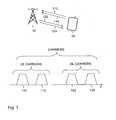
- Fig. 1shows an exemplary scenario of data transmission between a cellular network and a mobile terminal 20.
- the cellular networkis represented by a base station 10.
- the base station 10may generally correspond to an eNB in accordance with the 3GPP LTE specifications.
- the mobile terminal 20may for example be a mobile phone, a tablet computer or some other type of portable computing device, or a data stick.
- the base station 10is assumed to be a serving base station of the mobile terminal 20. That is to say, the base station 10 is assumed to be responsible for controlling operation of the mobile terminal 20 in the cellular network. This may in particular include controlling the establishment of connections between the mobile terminal 20 and the cellular network. Further, this may include scheduling of transmissions between the mobile terminal 20 and the cellular network.
- carrier aggregationmay be utilized when establishing a DL connection from the cellular network to the mobile terminal 20 and/or when establishing an UL connection from the mobile terminal 20 to the cellular network.
- a first UL carrier 112 and a second UL carrier 114are available for establishing the UL connection
- a first DL carrier 122 and a second DL carrier 124are available for establishing the DL connection.
- the first UL carrier 112 and the first DL carrier 122may be located in a first band of the total available frequency spectrum
- the second UL carrier 114 and the second DL carrier 124may be located in a second band of the total available frequency spectrum.
- the first and second bandmay be non-contiguous and each be composed of a band for UL carriers and a band for DL carriers. As illustrated in Fig. 1 , also the band for UL carriers and the band for DL carriers may be non-contiguous. For each band, the DL carriers may each be paired with a corresponding UL carrier. Such pair of DL carrier and corresponding UL carrier may also be referred to as cell. For example, in the scenario of Fig. 1 , the first UL carrier 112 could be paired with the first DL carrier 122, and the second UL carrier 114 could be paired with the second DL carrier 124. During cell assignment of the mobile terminal 20, the mobile terminal 20 may be assigned to the pair of DL carrier and corresponding UL carrier.
- the different cells associated with the different carriersmay also have different coverage areas. This is schematically illustrated in Fig. 2 .
- the coverage area of the first bandis illustrated by a dashed line, whereas the coverage area of the second band is illustrated by dotted lines.
- the different coverage areasmay be due to the first band and or the second band being transmitted by different antenna technologies.
- the first band and the second bandmay have different propagation characteristics or may be subject to different interference levels.
- the DL carriers of the first band and the second bandcould be transmitted by antennas at different locations or even by different base stations.
- the UL carriers of the first band and the second bandcould be received by antennas at different locations or even by different base stations. Utilization of carrier aggregation with respect to carriers received or transmitted by different base stations may require cooperation or coordination between the base stations, e.g., via a backhaul connection between the base stations.
- the base station 10may generally utilize the first DL carrier 122 and/or the second DL carrier 124 for establishing the DL connection from the cellular network to the mobile terminal 20, and the base station 10 may utilize the first UL carrier 112 and/or the second UL carrier 114 for establishing the UL connection from the mobile terminal 20 to the cellular network.
- the amount of DL data traffic directed from the cellular network to the mobile terminal 20is larger than the amount of UL data traffic directed from the mobile terminal 20 to the cellular network, e.g., due to downloading of data such as web content.
- Such asymmetryhas the effect that typically the main performance limitation resides in the DL connection.
- this asymmetrymay be addressed by combining more DL carriers than UL carriers. For example, in the scenario of Fig. 1 , it could be beneficial to combine the DL carriers 122 and 124 for establishing the DL connection to the mobile terminal 20, while utilizing one of the UL carriers 112, 114 for establishing the UL connection.
- the possibility to select between multiple available UL carriersmay be utilized for improving power efficiency of the mobile terminal 20.
- the base station 10estimates impact of usage of the different available UL carriers on the power consumption of the mobile terminal 20.
- the base station 10may then select one or more of the available UL carriers to be used for establishing the UL connection from the mobile terminal 20 to the cellular network.
- selecting the second UL carrier 114 from the second bandmay be the appropriate selection in view of power efficiency of the mobile terminal 20, e.g., because the mobile terminal 20 is located close to an antenna used for receiving the second UL carrier 14.
- the base station 10may use one or measurement reports provided by the mobile terminal 20.
- the base station 10may request such measurement reports from the mobile terminal 20 as needed.
- the mobile terminal 20may measure, for each of the available UL carriers, the transmit power required for performing an UL transmission on the UL carrier.
- the mobile terminal 20may be controlled to have a certain minimum transmit activity on all available UL carriers. For example, if all UL carriers can be used simultaneously, the base station may regularly schedule an UL transmission of data on each of the UL carriers. If simultaneous activation of all UL carriers is not possible, the base station 10 may regularly perform control signalling to the mobile terminal 20 to switch between different UL carrier configurations.
- the results of such measurementsmay be provided to the base station 10 in one or more measurement reports, and the base station 10 may evaluate the measurement reports to estimate the impact.
- the measurement of the transmit powers for individual UL carriersmay for example be handled and reported in a similar manner as the measurements specified in 3GPP Technical Specifications 25.215 or 36.214.
- the base station 10may send an indication to the mobile terminal 20 to configure the mobile terminal 20 to use the selected UL carriers for UL transmissions of data.
- the UL connectionmay be established using two or more UL carriers.
- scheduling of UL transmissionsmay be performed on the basis of the estimated impact.
- the base station 10may decide to schedule a certain UL transmission on the UL carriers estimated to have the lowest impact on power consumption of the mobile terminal 20.
- an UL carrier requiring lower transmit powermay be regarded as having the lower impact.
- more complex considerationsmay be taken into account. For example, if an UL carrier allows for achieving a significantly higher bitrate, also a higher transmit power on the UL carrier may be acceptable, if this allows for restricting usage of the UL carrier to a smaller time interval.
- the impact on power consumptionmay also be estimated from other types of measurements.
- the mobile terminal 20may perform measurements on the DL carriers. From such measurements, the power impact of the corresponding UL carriers may be deduced. This is possible because in many usage scenarios there is a close correlation between the characteristics of the DL carrier and its corresponding UL carrier.
- the deduction of the UL carrier characteristics, in particular the power impact of the individual UL carrier, from the measurements on the DL carriersmay be performed on the network side, e.g., at the base station 10, using one or more measurement reports on DL carrier characteristics received from the mobile terminal 20. Alternatively, the deduction of the UL carrier characteristics may also be performed at the mobile terminal. In some cases, the measurements could also be performed on the network side. For example, the transmit power of the DL carriers could be measured by the network and be used on the network side for deducing the transmit powers of the corresponding UL carriers.
- Fig. 3shows a flowchart for illustrating a method of data transmission between a mobile terminal and a cellular network. The method may be used for implementing the above concepts in a network component, e.g., in the base station 10.
- the network componentestablishes a DL connection from the cellular network to the mobile terminal.
- the DL connectionmay use one or more DL carriers.
- the DL connectionmay be established directly from the network component, but may also be established via other network components, e.g., base stations.
- the network componentidentifies multiple UL carriers which are available for establishing an UL connection from the mobile terminal to the cellular network.
- the network componentestimates impact of usage of the UL carriers on power consumption of the mobile terminal.
- the network componentmay receive one or more measurement reports on measurements performed by the mobile terminal.
- the measurement reportsmay then be used as a basis for estimating the impact.
- the measurement reportsmay in particular indicate, individually for each UL carrier, the transmit powers of the mobile terminal.
- the network componentmay request the measurement report from the mobile terminal.
- the network componentselects at least one of the UL carriers to be used for establishing the uplink connection. This is accomplished depending on the impact estimated at step 330.
- the network componentmay select at least two of the UL carriers for establishing the UL connection. Depending on the impact estimated at step 330, the network component may then decide on which one of the at least two UL carriers a certain UL transmission should be scheduled.
- the UL carriersmay be received by the same base station of the cellular network or by different base stations of the cellular network.
- Fig. 4shows a flowchart for illustrating a method of data transmission between a mobile terminal and a cellular network. The method may be used for implementing the above concepts in the mobile terminal, e.g., in the mobile terminal 20.
- the mobile terminalestablishes a DL connection from the cellular network to the mobile terminal.
- the DL connectionmay use one or more DL carriers.
- the mobile terminalidentifies multiple UL carriers which are available for establishing an UL connection from the mobile terminal to the cellular network.
- the mobile terminalmeasures its transmit power for each of the UL carriers. These measurements may be repeated periodically. The measurements may also be performed in response to receiving a request for a measurement report from the cellular network.
- the mobile terminalsends one or more measurement reports to the cellular network.
- the measurement reportsindicate the transmit powers measured at step 430 to the cellular network.
- a single measurement reportmay include the measured transmit powers for all UL carriers.
- the measured transmit powersmay be reported in individual measurement reports, e.g., one measurement report per UL carrier.
- the methods of Figs. 3 and 4may also be combined with each other.
- the method of Fig. 4may be used to provide the measurement report as input of step 330 of Fig. 3 , so that the measurement report can be used as a basis for estimating the impact on power consumption of the mobile terminal.
- Fig. 5shows an exemplary implementation of the base station 10.
- the base station 10includes a processor 13 which may be used to implement the above-described functionalities for power-aware selection and usage of one or more UL carriers.
- the processor 13may execute software or firmware 16 stored in a memory 15 of the base station 10.
- the base station 10may also include one or more transceivers 12-1, 12-2 and antennas 11-1, 11-2 for performing DL transmissions on one or more DL carriers and for receiving UL transmissions on one or more UL carriers.
- the transceivers 12-1, 12-2 and the antennas 11-1, 11-2may implement a radio interface of the base station.
- the base stationis illustrated as being equipped with two transceivers 12-1, 12-2 and antennas 11-1, 11-2, which may be used for independently supporting DL and UL transmission in different bands and/or for supporting MIMO technology.
- the base station 10may be equipped with a network interface 14.
- the network interface 14may be used for providing a backhaul connection to other components of the cellular network, e.g., to a data gateway for connecting to the internet or to other base stations.
- Fig. 6shows an exemplary implementation of the mobile terminal 20.
- the mobile terminal 20includes a processor 23 which may be used to implement the above-described functionalities for performing and reporting measurements of transmit power on individual UL carriers.
- the processor 23may execute software or firmware 26 stored in a memory 25 of the mobile terminal 20.
- the mobile terminal 20also includes a transceiver 22 and antenna 21 for receiving DL transmissions on one or more DL carriers and for performing UL transmissions on one or more UL carriers.
- the transceiver 22 and the antenna 21implement a radio interface of the mobile terminal 20.
- the mobile terminal 20may also be equipped with multiple transceivers and/or multiple antennas, e.g., for supporting MIMO technology.
- the exemplary implementations as described hereinare susceptible to various modifications.
- the conceptscould be applied in connection with various types of radio access technologies and for various types of mobile terminals.
- application of the conceptsis not limited to a cellular network supporting carrier aggregation or other types of multi-carrier transmission. Rather, the concepts may also be applied in other scenarios where multiple UL carriers are available for establishing a UL connection.
- other network componentsthan a base station may be used for implementing the concepts on the cellular network side.
- a control nodecould be used for this purpose, e.g., a Radio Network Controller.
- a relay nodecould perform implement functionalities as described for the base station.
- the evaluation of impact on power consumption and selection of UL carrier(s)is implemented on the network side, other implementations may locate at least a part of such functionalities in the mobile terminal. Still further, in addition to power consumption at the mobile terminal, various other criteria may be taken into account in the illustrated selection processes. Moreover, the concepts may be implemented by dedicated hardware and/or by software to be executed by one or more processors of a network component or a mobile terminal.
Landscapes
- Engineering & Computer Science (AREA)
- Signal Processing (AREA)
- Computer Networks & Wireless Communication (AREA)
- Quality & Reliability (AREA)
- Mobile Radio Communication Systems (AREA)
Description
- The present invention relates to a method of selecting an uplink carrier to be used by a mobile terminal and to a correspondingly configured network component.
- In cellular networks, efficient usage of available frequency resources is an important aspect. For example, when assuming a certain modulation and coding scheme (MCS) and optionally also Multiple Input Multiple Output format, the available frequency resources determine the achievable bitrates and capacity of the cellular network.
- In 3GPP (3rd Generation Partnership Project) cellular networks using LTE (Long Term Evolution) or WCDMA (Wideband Code Division Multiple Access), a concept denoted as "carrier aggregation" or "multi carrier" was introduced. In this case, multiple carriers can be combined to establish a downlink (DL) connection from the cellular network to a mobile terminal, and/or multiple carriers can be combined to establish an uplink (UL) connection from the mobile terminal to the cellular network. These carriers may be located in different bands of the frequency spectrum. By using multiple carriers for establishing the DL connection, the effective bandwidth and achievable bitrate of the DL connection may be increased as compared to a single carrier connection. Similarly, by using multiple carriers for establishing the UL connection the effective bandwidth and achievable bitrate of the UL connection may be increased as compared to a single carrier connection.
- The present concepts of combining multiple carriers mainly aim at improving performance of the cellular network, e.g., for providing increased bitrates or increasing capacity of the cellular network. However, there is also a general need for power efficiency of mobile terminals. Increased performance, e.g., in terms of bitrate, may in some cases even adversely affect power efficiency of mobile terminals.
GB 2 472 978 A - In
EP 2 523 491 A1 , control of a user equipment with respect to measurements on non-activated downlink component carriers is described. The user equipment can be instructed to transmit a sounding reference signal on an inactive uplink component carrier. The strength of the sounding reference signal on the inactive uplink component carrier can then be measured by a base station. Such measurement may then be used as a basis for activating the uplink component carrier. - In "Summary of the email discussion [68#23] LTE: CC activation/deactivation" by Ericsson, FT Ericsson, 3GPP TSG-RAN WG2 #68-Meeting, Valencia, Spain, January 18-22, 2010, Tdoc R2-100079, issues relating to activation and deactivation of component carriers in carrier aggregation scenarios are discussed. For example, it is suggested that channel quality measurements on configured but de-activated component carriers may be used as a basis for deciding on activation of uplink component carriers.
- According to an embodiment of the present invention, a method of data transmission between a mobile terminal and a cellular network is provided. According to the method, a DL connection from the cellular network to the mobile terminal is established. The DL connection uses one or more DL carriers. Further, multiple UL carriers which are available for establishing an UL connection from the mobile terminal to the cellular network are identified. Impact of usage of the UL carriers on power consumption of the mobile terminal is estimated. Depending on the estimated impact, the at least one of the UL carriers for establishing the UL connection is selected. In this way, the UL connection may be established using a configuration of one or more UL carriers which offers the lowest impact on the power consumption of the mobile terminal.
- According to an embodiment, the steps of the above method may be performed by a network component, e.g., by a base station. In this case, the network component may receive at least one report of measurements performed by the mobile terminal and use the received at least one measurement report as a basis for estimating the impact on the basis of the received at least one measurement report. Alternatively, the steps of the above method could be performed at the mobile terminal, thereby reducing signalling between the mobile terminal and the cellular network.
- According to an embodiment, the at least one measurement report indicates, for each of the UL carriers, a transmit power of the mobile terminal.
- According to an embodiment, at least two of the UL carriers may be selected for establishing the UL connection. Depending on the estimated impact, it may then be decided to schedule an UL transmission on one of the at least two UL carriers. In this way, the UL transmission may be scheduled on that one of the UL carriers which offers the lowest impact on the power consumption of the mobile terminal.
- According to an embodiment, the UL carriers are received by at least two different base stations of the cellular network. In addition or as an alternative, at least two of the UL carriers are received by the same base station of the cellular network.
- According to a further embodiment of the present invention, a method of data transmission between a mobile terminal and a cellular network is provided. According to the method the mobile terminal establishes a DL connection from the cellular network to the mobile terminal. The DL connection uses one or more DL carriers. The mobile terminal identifies multiple UL carriers which are available for establishing an UL connection from the mobile terminal to the cellular network. The mobile terminal measures a transmit power for each of the UL carriers and sends at least one measurement report indicating the measured transmit powers to the cellular network. Such measurement report allows for supporting accurate estimation of the impact of usage of the UL carriers by the mobile terminal.
- According to an embodiment, the mobile terminal receives a request for the measurement report from the cellular network and performs the measurement of the transmit powers and/or the sending of the measurement report in response to the request.
- According to a further embodiment of the present invention, a network component for a cellular network is provided. The network component comprises an interface for establishing a DL connection to a mobile terminal. The DL connection uses one or more DL carriers. Further, the network component comprises a processor. The processor is configured to identify multiple UL carriers which are available for establishing an UL connection from the mobile terminal to the cellular network, to estimate impact of usage of the UL carriers on power consumption of the mobile terminal and, depending on the estimated impact, select at least one of the UL carriers for establishing the UL connection.
- According to an embodiment, the processor is further configured to receive at least one report of measurements performed by the mobile terminal and to estimate the impact on the basis of the received at least one measurement report.
- According to an embodiment, the at least one measurement report indicates, for each of the UL carriers, a transmit power of the mobile terminal.
- According to an embodiment, the processor is further configured to select at least two of the UL carriers for establishing the UL connection and, depending on the estimated impact, decide to schedule an UL transmission on one of the at least two UL carriers.
- The interface of the network component may be a radio interface and is configured for transmitting the at least one DL carrier. This may for example be the case if the network component is a base station of the cellular network or a relay node. The radio interface may also be configured for receiving at least one of the UL carriers.
- According to a further embodiment of the present invention, a mobile terminal is provided. The mobile terminal comprises a radio interface for establishing a DL connection from a cellular network to the mobile terminal and for establishing an UL connection from the mobile terminal to the cellular network. The DL connection uses one or more DL carriers. Further, the mobile terminal comprises a processor. The processor is configured to identify multiple UL carriers which are available for establishing the UL connection, to measure a transmit power for each of the UL carriers, and to send at least one measurement report indicating the measured transmit powers to the cellular network.
- According to an embodiment, the processor is configured to receive a request for the measurement report from the cellular network and to perform the measurement of the transmit powers and/or the sending of the measurement report in response to the request.
- Although specific features described in the above summary and in the following detailed description are described in connection with specific embodiments and aspects, it is to be understood that the features of the embodiments and aspects may be combined with each other unless specifically noted otherwise.
- The invention will now be described in more detail with reference to the accompanying drawings.
Fig. 1 schematically illustrates aggregation of component carriers as utilized according to an embodiment of the present invention.Fig. 2 schematically illustrates exemplary coverage areas of different cells available to a mobile device.Fig. 3 shows a flowchart for illustrating a method according to an embodiment of the present invention.Fig. 4 shows a flowchart for illustrating a further method according to an embodiment of the present invention.Fig. 5 schematically illustrates a network component according to an embodiment of the present invention.Fig. 6 schematically illustrates a mobile terminal according to an embodiment of the present invention.- In the following, exemplary embodiments of the invention will be described in more detail. It has to be understood that the following description is given only for the purpose of illustrating the principles of the invention and is not to be taken in a limiting sense. Rather, the scope of the invention is defined only by the appended claims and is not intended to be limited by the exemplary embodiments hereinafter.
Fig. 1 shows an exemplary scenario of data transmission between a cellular network and amobile terminal 20. InFig. 1 , the cellular network is represented by abase station 10. In the following, it will be assumed that the cellular network implements LTE access technology. Accordingly, thebase station 10 may generally correspond to an eNB in accordance with the 3GPP LTE specifications. Themobile terminal 20 may for example be a mobile phone, a tablet computer or some other type of portable computing device, or a data stick.- The
base station 10 is assumed to be a serving base station of themobile terminal 20. That is to say, thebase station 10 is assumed to be responsible for controlling operation of themobile terminal 20 in the cellular network. This may in particular include controlling the establishment of connections between themobile terminal 20 and the cellular network. Further, this may include scheduling of transmissions between themobile terminal 20 and the cellular network. - As further illustrated in
Fig. 1 , carrier aggregation may be utilized when establishing a DL connection from the cellular network to themobile terminal 20 and/or when establishing an UL connection from themobile terminal 20 to the cellular network. In the exemplary scenario ofFig. 1 , afirst UL carrier 112 and asecond UL carrier 114 are available for establishing the UL connection, and afirst DL carrier 122 and asecond DL carrier 124 are available for establishing the DL connection. Thefirst UL carrier 112 and thefirst DL carrier 122 may be located in a first band of the total available frequency spectrum, and thesecond UL carrier 114 and thesecond DL carrier 124 may be located in a second band of the total available frequency spectrum. The first and second band may be non-contiguous and each be composed of a band for UL carriers and a band for DL carriers. As illustrated inFig. 1 , also the band for UL carriers and the band for DL carriers may be non-contiguous. For each band, the DL carriers may each be paired with a corresponding UL carrier. Such pair of DL carrier and corresponding UL carrier may also be referred to as cell. For example, in the scenario ofFig. 1 , thefirst UL carrier 112 could be paired with thefirst DL carrier 122, and thesecond UL carrier 114 could be paired with thesecond DL carrier 124. During cell assignment of themobile terminal 20, themobile terminal 20 may be assigned to the pair of DL carrier and corresponding UL carrier. - The different cells associated with the different carriers may also have different coverage areas. This is schematically illustrated in
Fig. 2 . InFig. 2 , the coverage area of the first band is illustrated by a dashed line, whereas the coverage area of the second band is illustrated by dotted lines. The different coverage areas may be due to the first band and or the second band being transmitted by different antenna technologies. Further, the first band and the second band may have different propagation characteristics or may be subject to different interference levels. According to a still further possibility, the DL carriers of the first band and the second band could be transmitted by antennas at different locations or even by different base stations. Similarly, the UL carriers of the first band and the second band could be received by antennas at different locations or even by different base stations. Utilization of carrier aggregation with respect to carriers received or transmitted by different base stations may require cooperation or coordination between the base stations, e.g., via a backhaul connection between the base stations. - In the scenario of
Fig. 1 , thebase station 10 may generally utilize thefirst DL carrier 122 and/or thesecond DL carrier 124 for establishing the DL connection from the cellular network to themobile terminal 20, and thebase station 10 may utilize thefirst UL carrier 112 and/or thesecond UL carrier 114 for establishing the UL connection from themobile terminal 20 to the cellular network. - In many usage scenarios, the amount of DL data traffic directed from the cellular network to the
mobile terminal 20 is larger than the amount of UL data traffic directed from themobile terminal 20 to the cellular network, e.g., due to downloading of data such as web content. Such asymmetry has the effect that typically the main performance limitation resides in the DL connection. When utilizing carrier aggregation, this asymmetry may be addressed by combining more DL carriers than UL carriers. For example, in the scenario ofFig. 1 , it could be beneficial to combine theDL carriers mobile terminal 20, while utilizing one of theUL carriers - Accordingly, it is possible to utilize only a part of the
available UL carriers mobile terminal 20 than needed for establishing the UL connection. Accordingly, there is freedom to select which UL carrier should be used for establishing the UL connection and performing UL transmissions. - According to concepts as explained in the following, the possibility to select between multiple available UL carriers may be utilized for improving power efficiency of the
mobile terminal 20. For this purpose, thebase station 10 estimates impact of usage of the different available UL carriers on the power consumption of themobile terminal 20. In view of the estimated impact, thebase station 10 may then select one or more of the available UL carriers to be used for establishing the UL connection from themobile terminal 20 to the cellular network. In particular, it becomes possible to select a configuration of one or more UL carriers which offers the lowest impact on power consumption of the mobile terminal. - For example, when referring to the scenario of
Fig. 1 and2 , selecting thesecond UL carrier 114 from the second band may be the appropriate selection in view of power efficiency of themobile terminal 20, e.g., because themobile terminal 20 is located close to an antenna used for receiving thesecond UL carrier 14. - For estimating the impact, the
base station 10 may use one or measurement reports provided by themobile terminal 20. Thebase station 10 may request such measurement reports from themobile terminal 20 as needed. In response to such request, themobile terminal 20 may measure, for each of the available UL carriers, the transmit power required for performing an UL transmission on the UL carrier. For performing the measurements, themobile terminal 20 may be controlled to have a certain minimum transmit activity on all available UL carriers. For example, if all UL carriers can be used simultaneously, the base station may regularly schedule an UL transmission of data on each of the UL carriers. If simultaneous activation of all UL carriers is not possible, thebase station 10 may regularly perform control signalling to themobile terminal 20 to switch between different UL carrier configurations. - The results of such measurements may be provided to the
base station 10 in one or more measurement reports, and thebase station 10 may evaluate the measurement reports to estimate the impact. The measurement of the transmit powers for individual UL carriers may for example be handled and reported in a similar manner as the measurements specified in 3GPP Technical Specifications 25.215 or 36.214. - Having selected the UL carrier(s), the
base station 10 may send an indication to themobile terminal 20 to configure themobile terminal 20 to use the selected UL carriers for UL transmissions of data. - In some scenarios, the UL connection may be established using two or more UL carriers. In such cases, also scheduling of UL transmissions may be performed on the basis of the estimated impact. In particular, the
base station 10 may decide to schedule a certain UL transmission on the UL carriers estimated to have the lowest impact on power consumption of themobile terminal 20. - Typically, an UL carrier requiring lower transmit power may be regarded as having the lower impact. However, also more complex considerations may be taken into account. For example, if an UL carrier allows for achieving a significantly higher bitrate, also a higher transmit power on the UL carrier may be acceptable, if this allows for restricting usage of the UL carrier to a smaller time interval.
- In some scenarios, the impact on power consumption may also be estimated from other types of measurements. For example, the
mobile terminal 20 may perform measurements on the DL carriers. From such measurements, the power impact of the corresponding UL carriers may be deduced. This is possible because in many usage scenarios there is a close correlation between the characteristics of the DL carrier and its corresponding UL carrier. The deduction of the UL carrier characteristics, in particular the power impact of the individual UL carrier, from the measurements on the DL carriers may be performed on the network side, e.g., at thebase station 10, using one or more measurement reports on DL carrier characteristics received from themobile terminal 20. Alternatively, the deduction of the UL carrier characteristics may also be performed at the mobile terminal. In some cases, the measurements could also be performed on the network side. For example, the transmit power of the DL carriers could be measured by the network and be used on the network side for deducing the transmit powers of the corresponding UL carriers. Fig. 3 shows a flowchart for illustrating a method of data transmission between a mobile terminal and a cellular network. The method may be used for implementing the above concepts in a network component, e.g., in thebase station 10.- At
step 310, the network component establishes a DL connection from the cellular network to the mobile terminal. The DL connection may use one or more DL carriers. The DL connection may be established directly from the network component, but may also be established via other network components, e.g., base stations. - At
step 320, the network component identifies multiple UL carriers which are available for establishing an UL connection from the mobile terminal to the cellular network. - At
step 330, the network component estimates impact of usage of the UL carriers on power consumption of the mobile terminal. For this purpose, the network component may receive one or more measurement reports on measurements performed by the mobile terminal. The measurement reports may then be used as a basis for estimating the impact. The measurement reports may in particular indicate, individually for each UL carrier, the transmit powers of the mobile terminal. The network component may request the measurement report from the mobile terminal. - At
step 340, the network component selects at least one of the UL carriers to be used for establishing the uplink connection. This is accomplished depending on the impact estimated atstep 330. - In some scenarios, the network component may select at least two of the UL carriers for establishing the UL connection. Depending on the impact estimated at
step 330, the network component may then decide on which one of the at least two UL carriers a certain UL transmission should be scheduled. - The UL carriers may be received by the same base station of the cellular network or by different base stations of the cellular network.
Fig. 4 shows a flowchart for illustrating a method of data transmission between a mobile terminal and a cellular network. The method may be used for implementing the above concepts in the mobile terminal, e.g., in themobile terminal 20.- At
step 410, the mobile terminal establishes a DL connection from the cellular network to the mobile terminal. The DL connection may use one or more DL carriers. - At
step 420, the mobile terminal identifies multiple UL carriers which are available for establishing an UL connection from the mobile terminal to the cellular network. - At
step 430, the mobile terminal measures its transmit power for each of the UL carriers. These measurements may be repeated periodically. The measurements may also be performed in response to receiving a request for a measurement report from the cellular network. - At
step 440 the mobile terminal sends one or more measurement reports to the cellular network. The measurement reports indicate the transmit powers measured atstep 430 to the cellular network. In some implementation, a single measurement report may include the measured transmit powers for all UL carriers. In other implementations, the measured transmit powers may be reported in individual measurement reports, e.g., one measurement report per UL carrier. - The methods of
Figs. 3 and4 may also be combined with each other. In particular, the method ofFig. 4 may be used to provide the measurement report as input ofstep 330 ofFig. 3 , so that the measurement report can be used as a basis for estimating the impact on power consumption of the mobile terminal. Fig. 5 shows an exemplary implementation of thebase station 10. As illustrated, thebase station 10 includes aprocessor 13 which may be used to implement the above-described functionalities for power-aware selection and usage of one or more UL carriers. For implementing these functionalities, theprocessor 13 may execute software orfirmware 16 stored in amemory 15 of thebase station 10. As further illustrated, thebase station 10 may also include one or more transceivers 12-1, 12-2 and antennas 11-1, 11-2 for performing DL transmissions on one or more DL carriers and for receiving UL transmissions on one or more UL carriers. The transceivers 12-1, 12-2 and the antennas 11-1, 11-2 may implement a radio interface of the base station. In the illustrated example, the base station is illustrated as being equipped with two transceivers 12-1, 12-2 and antennas 11-1, 11-2, which may be used for independently supporting DL and UL transmission in different bands and/or for supporting MIMO technology. Still further, thebase station 10 may be equipped with anetwork interface 14. Thenetwork interface 14 may be used for providing a backhaul connection to other components of the cellular network, e.g., to a data gateway for connecting to the internet or to other base stations.Fig. 6 shows an exemplary implementation of themobile terminal 20. As illustrated, themobile terminal 20 includes aprocessor 23 which may be used to implement the above-described functionalities for performing and reporting measurements of transmit power on individual UL carriers. For implementing these functionalities, theprocessor 23 may execute software orfirmware 26 stored in amemory 25 of themobile terminal 20. As further illustrated, themobile terminal 20 also includes atransceiver 22 andantenna 21 for receiving DL transmissions on one or more DL carriers and for performing UL transmissions on one or more UL carriers. Thetransceiver 22 and theantenna 21 implement a radio interface of themobile terminal 20. In some implementations, themobile terminal 20 may also be equipped with multiple transceivers and/or multiple antennas, e.g., for supporting MIMO technology.- It is to be understood that the exemplary implementations as described herein are susceptible to various modifications. For example, the concepts could be applied in connection with various types of radio access technologies and for various types of mobile terminals. Also, application of the concepts is not limited to a cellular network supporting carrier aggregation or other types of multi-carrier transmission. Rather, the concepts may also be applied in other scenarios where multiple UL carriers are available for establishing a UL connection. Also, other network components than a base station may be used for implementing the concepts on the cellular network side. For example, a control node could be used for this purpose, e.g., a Radio Network Controller. Also, a relay node could perform implement functionalities as described for the base station. Moreover, although in the illustrated exemplary implementations the evaluation of impact on power consumption and selection of UL carrier(s) is implemented on the network side, other implementations may locate at least a part of such functionalities in the mobile terminal. Still further, in addition to power consumption at the mobile terminal, various other criteria may be taken into account in the illustrated selection processes. Moreover, the concepts may be implemented by dedicated hardware and/or by software to be executed by one or more processors of a network component or a mobile terminal.
Claims (14)
- A method of data transmission between a mobile terminal (20) and a cellular network, the method comprising:establishing a downlink connection from the cellular network to the mobile terminal (20), said downlink connection using one or more downlink carriers (122, 124);identifying multiple uplink carriers (112, 114) which are available for establishing an uplink connection from the mobile terminal (20) to the cellular network;estimating impact of usage of the uplink carriers (112, 114) on power consumption of the mobile terminal (20); anddepending on the estimated impact, selecting a configuration of at least one of the uplink carriers (112, 114) for establishing the uplink connection for improving power efficiency of the mobile terminal.
- The method according to claim 1, comprising:a network component (10) receiving at least one report of measurements performed by the mobile terminal (20); andthe network component (10) estimating the impact on the basis of the received at least one measurement report.
- The method according to claim 2,
wherein the at least one measurement report indicates, for each of the uplink carriers, a transmit power of the mobile terminal (20). - The method according to any one of the preceding claims, comprising:selecting at least two of the uplink carriers (112, 114) for establishing the uplink connection; anddepending on the estimated impact, the network component (10) deciding to schedule an uplink transmission on one of the at least two uplink carriers (112, 114).
- The method according to any one of the preceding claims,
wherein the uplink carriers (112, 114) are received by at least two different base stations (10) of the cellular network. - The method according to any one of the preceding claims,
wherein at least two of the uplink carriers (112, 114) are received by the same base station (10) of the cellular network. - A method of data transmission between a mobile terminal (20) and a cellular network, the method comprising:the mobile terminal (20) establishing a downlink connection from the cellular network to the mobile terminal (20), said downlink connection using one or more downlink carriers (122, 124);the mobile terminal (20) identifying multiple uplink carriers (112, 114) which are available for establishing an uplink connection from the mobile terminal (20) to the cellular network;the mobile terminal (20) receiving a request for at least one measurement report from the cellular network;the mobile terminal (20), in response to the request, measuring for each of the uplink carriers (112, 114), a transmit power required for performing an uplink transmission on the uplink carrier (112, 114);the mobile terminal (20) sending the measurement report indicating the measured transmit powers to the cellular network; andthe mobile terminal using a selected configuration of the uplink carrier.
- A network component (10) for a cellular network, the network component (10) comprising
an interface (11-1, 11-2, 12-1, 12-2) for establishing a downlink connection to a mobile terminal (20), said downlink connection using one or more downlink carriers (122, 124); and
a processor (13), the processor (13) being configured to:- identify multiple uplink carriers (112, 114) which are available for establishing an uplink connection from the mobile terminal (20) to the cellular network;- estimate impact of usage of the uplink carriers (112, 114) on power consumption of the mobile terminal (20); and- depending on the estimated impact, select a configuration of at least one of the up-link carriers (112, 114) for establishing the uplink connection for improving power efficiency of the mobile terminal. - The network component (10) according to claim 8,
wherein the processor (13) is further configured to receive at least one report of measurements performed by the mobile terminal (20) and to estimate the impact on the basis of the received at least one measurement report. - The network component (10) according to claim 8 or 9,
wherein the at least one measurement report indicates, for each of the uplink carriers, a transmit power of the mobile terminal (20). - The network component (10) according to any one of claims 8 to 10,
wherein the processor (23) is further configured to:- select at least two of the uplink carriers (112, 114) for establishing the uplink connection, and- depending on the estimated impact, decide to schedule an uplink transmission on one of the at least two uplink carriers (112, 114). - The network component (10) according to any one of claims 8 to 11,
wherein the interface (11-1, 11-2, 12-1, 12-2) is a radio interface and is configured for transmitting the at least one downlink carrier (122, 124). - The network component (10) according to claim 12,
wherein the interface (11-1, 11-2, 12-1, 12-2) is further configured for receiving at least one of the uplink carriers (112, 114). - A mobile terminal (20), comprising:a radio interface (21, 22) for establishing a downlink connection from a cellular network to the mobile terminal (20), said downlink connection using one or more downlink carriers (122, 124), and for establishing an uplink connection from the mobile terminal (20) to the cellular network; anda processor (23), wherein the processor (23) is configured to:- identify multiple uplink carriers (112, 114) which are available for establishing the uplink connection;- receive a request for at least one measurement report from the cellular network;
for each of the uplink carriers (112, 114), measure, in response to the request, a transmit power required for performing an uplink transmission on the uplink carrier (112, 114);- send the measurement report indicating the measured transmit powers to the cellular network;and- use a selected configuration of the uplink carriers.
Priority Applications (3)
| Application Number | Priority Date | Filing Date | Title |
|---|---|---|---|
| EP13000218.1AEP2757730B1 (en) | 2013-01-16 | 2013-01-16 | Power efficient control of uplink carrier usage by mobile terminal |
| PCT/EP2014/050659WO2014111400A1 (en) | 2013-01-16 | 2014-01-15 | Power efficient control of uplink carrier usage by mobile terminal |
| US14/761,037US9860854B2 (en) | 2013-01-16 | 2014-01-15 | Power efficient control of uplink carrier usage by mobile terminal |
Applications Claiming Priority (1)
| Application Number | Priority Date | Filing Date | Title |
|---|---|---|---|
| EP13000218.1AEP2757730B1 (en) | 2013-01-16 | 2013-01-16 | Power efficient control of uplink carrier usage by mobile terminal |
Publications (2)
| Publication Number | Publication Date |
|---|---|
| EP2757730A1 EP2757730A1 (en) | 2014-07-23 |
| EP2757730B1true EP2757730B1 (en) | 2015-11-18 |
Family
ID=47594484
Family Applications (1)
| Application Number | Title | Priority Date | Filing Date |
|---|---|---|---|
| EP13000218.1AActiveEP2757730B1 (en) | 2013-01-16 | 2013-01-16 | Power efficient control of uplink carrier usage by mobile terminal |
Country Status (3)
| Country | Link |
|---|---|
| US (1) | US9860854B2 (en) |
| EP (1) | EP2757730B1 (en) |
| WO (1) | WO2014111400A1 (en) |
Families Citing this family (1)
| Publication number | Priority date | Publication date | Assignee | Title |
|---|---|---|---|---|
| CN110677229B (en)* | 2014-05-09 | 2022-03-25 | 富士通互联科技有限公司 | Wireless communication system, base station, and terminal |
Family Cites Families (10)
| Publication number | Priority date | Publication date | Assignee | Title |
|---|---|---|---|---|
| US9155077B2 (en)* | 2012-09-28 | 2015-10-06 | Blackberry Limited | Methods and apparatus for enabling further enhancements to flexible subframes in LTE heterogeneous networks |
| US8416724B2 (en)* | 2007-07-03 | 2013-04-09 | Motorola Solutions, Inc. | Dynamic selection of channel assignment for preserving power in a wireless device |
| EP2265068B1 (en)* | 2009-06-17 | 2016-12-14 | IDTP Holdings, Inc. | Scheduling data transmissions between a mobile terminal and a base station in a wireless communications network using component carriers |
| GB2472978A (en)* | 2009-08-24 | 2011-03-02 | Vodafone Plc | A multi-antenna receiver is switched between receiver diversity mode and carrier aggregation mode on the basis of network or/and terminal parameters |
| WO2011039969A1 (en)* | 2009-09-29 | 2011-04-07 | パナソニック株式会社 | Wireless communication apparatus, wireless communication base station and wireless communication system |
| CN102098784B (en)* | 2009-12-14 | 2014-06-04 | 华为技术有限公司 | Resource allocation method and equipment |
| JP5606553B2 (en)* | 2010-01-08 | 2014-10-15 | アルカテル−ルーセント | Method and apparatus for controlling user equipment to measure inactive downlink component carriers |
| CN102792752B (en)* | 2010-04-30 | 2016-06-22 | 诺基亚技术有限公司 | Subscriber equipment carrier activation |
| JP2013149712A (en)* | 2012-01-18 | 2013-08-01 | Toshiba Corp | Method of manufacturing semiconductor device |
| US9329662B2 (en)* | 2012-08-29 | 2016-05-03 | Nokia Technologies Oy | Enhanced power saving optimized configuration handling |
- 2013
- 2013-01-16EPEP13000218.1Apatent/EP2757730B1/enactiveActive
- 2014
- 2014-01-15WOPCT/EP2014/050659patent/WO2014111400A1/enactiveApplication Filing
- 2014-01-15USUS14/761,037patent/US9860854B2/enactiveActive
Also Published As
| Publication number | Publication date |
|---|---|
| US20150351047A1 (en) | 2015-12-03 |
| US9860854B2 (en) | 2018-01-02 |
| WO2014111400A1 (en) | 2014-07-24 |
| EP2757730A1 (en) | 2014-07-23 |
Similar Documents
| Publication | Publication Date | Title |
|---|---|---|
| EP3536005B1 (en) | Cooperation between nodes operating in licensed and unlicensed spectrum for channel access in unlicensed spectrum | |
| US8792881B2 (en) | Method and apparatus for determining cell for executing comp in multi-cell environment | |
| US10098129B2 (en) | Handling of simultaneous network communication transmission and D2D communication reception or simultaneous network communication reception and D2D communication transmission | |
| US10110294B2 (en) | Adaptive use of receiver diversity | |
| US10511988B2 (en) | Receiving path scheduling in a wireless communication system for a wireless communication device having multiple receiving paths and multiple SIMs | |
| KR101740446B1 (en) | Method and apparatus for determining a cooperative terminal | |
| US10237880B2 (en) | Method and radio access point for handling communication between wireless devices | |
| US20150382375A1 (en) | Full duplex operation in a wireless communication network | |
| JP5069283B2 (en) | User apparatus, base station apparatus and communication control method in mobile communication system | |
| EP3132555B1 (en) | Uplink based selection of downlink connectivity configuration | |
| US20130281143A1 (en) | Method and apparatus for interference-aware wireless communications | |
| JP2012503347A (en) | Channel measurements in integrated spectrum radio systems. | |
| CN104938008A (en) | Resource Allocation in Wireless Communication Networks | |
| CN105359444A (en) | In-device coexistence of wireless communication technologies | |
| JP2015159539A (en) | System and method for controlling activation of carrier aggregation | |
| US20190254043A1 (en) | Apparatuses, methods and computer programs for implementing fairness and complexity-constrained a non-orthogonal multiple access (noma) scheme | |
| CN103518412A (en) | Method, radio network controller, radio base station and user equipment for selecting downlink mode | |
| WO2007094415A1 (en) | Mobile communication system, mobile station device, base station device, and mobile communication method | |
| KR101568705B1 (en) | A method of pairing two terminals using a dummy terminal | |
| Li et al. | Adaptive TDD UL/DL slot utilization for cellular controlled D2D communications | |
| EP2757730B1 (en) | Power efficient control of uplink carrier usage by mobile terminal | |
| US10432383B2 (en) | Method for enabling a base station to decode data received from a first wireless device using a network coded form of the data received from a second wireless device | |
| WO2015026276A1 (en) | Method and controlling node for controlling radio communication in a cellular network | |
| EP4366182B1 (en) | Devices, methods and apparatuses for uplink transmission | |
| JP2020500479A (en) | Data transmission method and device |
Legal Events
| Date | Code | Title | Description |
|---|---|---|---|
| PUAI | Public reference made under article 153(3) epc to a published international application that has entered the european phase | Free format text:ORIGINAL CODE: 0009012 | |
| 17P | Request for examination filed | Effective date:20130116 | |
| AK | Designated contracting states | Kind code of ref document:A1 Designated state(s):AL AT BE BG CH CY CZ DE DK EE ES FI FR GB GR HR HU IE IS IT LI LT LU LV MC MK MT NL NO PL PT RO RS SE SI SK SM TR | |
| AX | Request for extension of the european patent | Extension state:BA ME | |
| R17P | Request for examination filed (corrected) | Effective date:20150123 | |
| RBV | Designated contracting states (corrected) | Designated state(s):AL AT BE BG CH CY CZ DE DK EE ES FI FR GB GR HR HU IE IS IT LI LT LU LV MC MK MT NL NO PL PT RO RS SE SI SK SM TR | |
| GRAP | Despatch of communication of intention to grant a patent | Free format text:ORIGINAL CODE: EPIDOSNIGR1 | |
| INTG | Intention to grant announced | Effective date:20150630 | |
| GRAS | Grant fee paid | Free format text:ORIGINAL CODE: EPIDOSNIGR3 | |
| GRAA | (expected) grant | Free format text:ORIGINAL CODE: 0009210 | |
| RIN1 | Information on inventor provided before grant (corrected) | Inventor name:YING, ZHINONG Inventor name:LJUNG, RICKARD Inventor name:BENGTSSON, ERIK | |
| AK | Designated contracting states | Kind code of ref document:B1 Designated state(s):AL AT BE BG CH CY CZ DE DK EE ES FI FR GB GR HR HU IE IS IT LI LT LU LV MC MK MT NL NO PL PT RO RS SE SI SK SM TR | |
| REG | Reference to a national code | Ref country code:GB Ref legal event code:FG4D | |
| REG | Reference to a national code | Ref country code:CH Ref legal event code:EP | |
| REG | Reference to a national code | Ref country code:AT Ref legal event code:REF Ref document number:762014 Country of ref document:AT Kind code of ref document:T Effective date:20151215 | |
| REG | Reference to a national code | Ref country code:IE Ref legal event code:FG4D | |
| REG | Reference to a national code | Ref country code:DE Ref legal event code:R096 Ref document number:602013003789 Country of ref document:DE | |
| REG | Reference to a national code | Ref country code:NL Ref legal event code:FP | |
| REG | Reference to a national code | Ref country code:LT Ref legal event code:MG4D | |
| REG | Reference to a national code | Ref country code:AT Ref legal event code:MK05 Ref document number:762014 Country of ref document:AT Kind code of ref document:T Effective date:20151118 | |
| PG25 | Lapsed in a contracting state [announced via postgrant information from national office to epo] | Ref country code:IT Free format text:LAPSE BECAUSE OF FAILURE TO SUBMIT A TRANSLATION OF THE DESCRIPTION OR TO PAY THE FEE WITHIN THE PRESCRIBED TIME-LIMIT Effective date:20151118 Ref country code:IS Free format text:LAPSE BECAUSE OF FAILURE TO SUBMIT A TRANSLATION OF THE DESCRIPTION OR TO PAY THE FEE WITHIN THE PRESCRIBED TIME-LIMIT Effective date:20160318 Ref country code:ES Free format text:LAPSE BECAUSE OF FAILURE TO SUBMIT A TRANSLATION OF THE DESCRIPTION OR TO PAY THE FEE WITHIN THE PRESCRIBED TIME-LIMIT Effective date:20151118 Ref country code:LT Free format text:LAPSE BECAUSE OF FAILURE TO SUBMIT A TRANSLATION OF THE DESCRIPTION OR TO PAY THE FEE WITHIN THE PRESCRIBED TIME-LIMIT Effective date:20151118 Ref country code:NO Free format text:LAPSE BECAUSE OF FAILURE TO SUBMIT A TRANSLATION OF THE DESCRIPTION OR TO PAY THE FEE WITHIN THE PRESCRIBED TIME-LIMIT Effective date:20160218 Ref country code:HR Free format text:LAPSE BECAUSE OF FAILURE TO SUBMIT A TRANSLATION OF THE DESCRIPTION OR TO PAY THE FEE WITHIN THE PRESCRIBED TIME-LIMIT Effective date:20151118 | |
| PG25 | Lapsed in a contracting state [announced via postgrant information from national office to epo] | Ref country code:BE Free format text:LAPSE BECAUSE OF NON-PAYMENT OF DUE FEES Effective date:20160131 Ref country code:GR Free format text:LAPSE BECAUSE OF FAILURE TO SUBMIT A TRANSLATION OF THE DESCRIPTION OR TO PAY THE FEE WITHIN THE PRESCRIBED TIME-LIMIT Effective date:20160219 Ref country code:RS Free format text:LAPSE BECAUSE OF FAILURE TO SUBMIT A TRANSLATION OF THE DESCRIPTION OR TO PAY THE FEE WITHIN THE PRESCRIBED TIME-LIMIT Effective date:20151118 Ref country code:SE Free format text:LAPSE BECAUSE OF FAILURE TO SUBMIT A TRANSLATION OF THE DESCRIPTION OR TO PAY THE FEE WITHIN THE PRESCRIBED TIME-LIMIT Effective date:20151118 Ref country code:PL Free format text:LAPSE BECAUSE OF FAILURE TO SUBMIT A TRANSLATION OF THE DESCRIPTION OR TO PAY THE FEE WITHIN THE PRESCRIBED TIME-LIMIT Effective date:20151118 Ref country code:FI Free format text:LAPSE BECAUSE OF FAILURE TO SUBMIT A TRANSLATION OF THE DESCRIPTION OR TO PAY THE FEE WITHIN THE PRESCRIBED TIME-LIMIT Effective date:20151118 Ref country code:PT Free format text:LAPSE BECAUSE OF FAILURE TO SUBMIT A TRANSLATION OF THE DESCRIPTION OR TO PAY THE FEE WITHIN THE PRESCRIBED TIME-LIMIT Effective date:20160318 Ref country code:AT Free format text:LAPSE BECAUSE OF FAILURE TO SUBMIT A TRANSLATION OF THE DESCRIPTION OR TO PAY THE FEE WITHIN THE PRESCRIBED TIME-LIMIT Effective date:20151118 Ref country code:LV Free format text:LAPSE BECAUSE OF FAILURE TO SUBMIT A TRANSLATION OF THE DESCRIPTION OR TO PAY THE FEE WITHIN THE PRESCRIBED TIME-LIMIT Effective date:20151118 | |
| PG25 | Lapsed in a contracting state [announced via postgrant information from national office to epo] | Ref country code:CZ Free format text:LAPSE BECAUSE OF FAILURE TO SUBMIT A TRANSLATION OF THE DESCRIPTION OR TO PAY THE FEE WITHIN THE PRESCRIBED TIME-LIMIT Effective date:20151118 | |
| REG | Reference to a national code | Ref country code:DE Ref legal event code:R097 Ref document number:602013003789 Country of ref document:DE | |
| PG25 | Lapsed in a contracting state [announced via postgrant information from national office to epo] | Ref country code:RO Free format text:LAPSE BECAUSE OF FAILURE TO SUBMIT A TRANSLATION OF THE DESCRIPTION OR TO PAY THE FEE WITHIN THE PRESCRIBED TIME-LIMIT Effective date:20151118 Ref country code:SM Free format text:LAPSE BECAUSE OF FAILURE TO SUBMIT A TRANSLATION OF THE DESCRIPTION OR TO PAY THE FEE WITHIN THE PRESCRIBED TIME-LIMIT Effective date:20151118 Ref country code:EE Free format text:LAPSE BECAUSE OF FAILURE TO SUBMIT A TRANSLATION OF THE DESCRIPTION OR TO PAY THE FEE WITHIN THE PRESCRIBED TIME-LIMIT Effective date:20151118 Ref country code:SK Free format text:LAPSE BECAUSE OF FAILURE TO SUBMIT A TRANSLATION OF THE DESCRIPTION OR TO PAY THE FEE WITHIN THE PRESCRIBED TIME-LIMIT Effective date:20151118 Ref country code:DK Free format text:LAPSE BECAUSE OF FAILURE TO SUBMIT A TRANSLATION OF THE DESCRIPTION OR TO PAY THE FEE WITHIN THE PRESCRIBED TIME-LIMIT Effective date:20151118 Ref country code:LU Free format text:LAPSE BECAUSE OF FAILURE TO SUBMIT A TRANSLATION OF THE DESCRIPTION OR TO PAY THE FEE WITHIN THE PRESCRIBED TIME-LIMIT Effective date:20160116 | |
| REG | Reference to a national code | Ref country code:CH Ref legal event code:PL | |
| PLBE | No opposition filed within time limit | Free format text:ORIGINAL CODE: 0009261 | |
| STAA | Information on the status of an ep patent application or granted ep patent | Free format text:STATUS: NO OPPOSITION FILED WITHIN TIME LIMIT | |
| PG25 | Lapsed in a contracting state [announced via postgrant information from national office to epo] | Ref country code:MC Free format text:LAPSE BECAUSE OF FAILURE TO SUBMIT A TRANSLATION OF THE DESCRIPTION OR TO PAY THE FEE WITHIN THE PRESCRIBED TIME-LIMIT Effective date:20151118 | |
| 26N | No opposition filed | Effective date:20160819 | |
| REG | Reference to a national code | Ref country code:FR Ref legal event code:ST Effective date:20160930 | |
| PG25 | Lapsed in a contracting state [announced via postgrant information from national office to epo] | Ref country code:LI Free format text:LAPSE BECAUSE OF NON-PAYMENT OF DUE FEES Effective date:20160131 Ref country code:CH Free format text:LAPSE BECAUSE OF NON-PAYMENT OF DUE FEES Effective date:20160131 | |
| REG | Reference to a national code | Ref country code:IE Ref legal event code:MM4A | |
| PG25 | Lapsed in a contracting state [announced via postgrant information from national office to epo] | Ref country code:FR Free format text:LAPSE BECAUSE OF NON-PAYMENT OF DUE FEES Effective date:20160201 Ref country code:SI Free format text:LAPSE BECAUSE OF FAILURE TO SUBMIT A TRANSLATION OF THE DESCRIPTION OR TO PAY THE FEE WITHIN THE PRESCRIBED TIME-LIMIT Effective date:20151118 | |
| PG25 | Lapsed in a contracting state [announced via postgrant information from national office to epo] | Ref country code:BE Free format text:LAPSE BECAUSE OF FAILURE TO SUBMIT A TRANSLATION OF THE DESCRIPTION OR TO PAY THE FEE WITHIN THE PRESCRIBED TIME-LIMIT Effective date:20151118 | |
| PG25 | Lapsed in a contracting state [announced via postgrant information from national office to epo] | Ref country code:IE Free format text:LAPSE BECAUSE OF NON-PAYMENT OF DUE FEES Effective date:20160116 | |
| PG25 | Lapsed in a contracting state [announced via postgrant information from national office to epo] | Ref country code:MT Free format text:LAPSE BECAUSE OF FAILURE TO SUBMIT A TRANSLATION OF THE DESCRIPTION OR TO PAY THE FEE WITHIN THE PRESCRIBED TIME-LIMIT Effective date:20151118 | |
| GBPC | Gb: european patent ceased through non-payment of renewal fee | Effective date:20170116 | |
| PG25 | Lapsed in a contracting state [announced via postgrant information from national office to epo] | Ref country code:GB Free format text:LAPSE BECAUSE OF NON-PAYMENT OF DUE FEES Effective date:20170116 | |
| PG25 | Lapsed in a contracting state [announced via postgrant information from national office to epo] | Ref country code:CY Free format text:LAPSE BECAUSE OF FAILURE TO SUBMIT A TRANSLATION OF THE DESCRIPTION OR TO PAY THE FEE WITHIN THE PRESCRIBED TIME-LIMIT Effective date:20151118 Ref country code:HU Free format text:LAPSE BECAUSE OF FAILURE TO SUBMIT A TRANSLATION OF THE DESCRIPTION OR TO PAY THE FEE WITHIN THE PRESCRIBED TIME-LIMIT; INVALID AB INITIO Effective date:20130116 | |
| PG25 | Lapsed in a contracting state [announced via postgrant information from national office to epo] | Ref country code:MT Free format text:LAPSE BECAUSE OF FAILURE TO SUBMIT A TRANSLATION OF THE DESCRIPTION OR TO PAY THE FEE WITHIN THE PRESCRIBED TIME-LIMIT Effective date:20160131 Ref country code:MK Free format text:LAPSE BECAUSE OF FAILURE TO SUBMIT A TRANSLATION OF THE DESCRIPTION OR TO PAY THE FEE WITHIN THE PRESCRIBED TIME-LIMIT Effective date:20151118 Ref country code:TR Free format text:LAPSE BECAUSE OF FAILURE TO SUBMIT A TRANSLATION OF THE DESCRIPTION OR TO PAY THE FEE WITHIN THE PRESCRIBED TIME-LIMIT Effective date:20151118 | |
| PG25 | Lapsed in a contracting state [announced via postgrant information from national office to epo] | Ref country code:BG Free format text:LAPSE BECAUSE OF FAILURE TO SUBMIT A TRANSLATION OF THE DESCRIPTION OR TO PAY THE FEE WITHIN THE PRESCRIBED TIME-LIMIT Effective date:20151118 | |
| PG25 | Lapsed in a contracting state [announced via postgrant information from national office to epo] | Ref country code:AL Free format text:LAPSE BECAUSE OF FAILURE TO SUBMIT A TRANSLATION OF THE DESCRIPTION OR TO PAY THE FEE WITHIN THE PRESCRIBED TIME-LIMIT Effective date:20151118 | |
| PGFP | Annual fee paid to national office [announced via postgrant information from national office to epo] | Ref country code:ES Payment date:20181214 Year of fee payment:6 | |
| REG | Reference to a national code | Ref country code:NL Ref legal event code:MM Effective date:20200201 | |
| PG25 | Lapsed in a contracting state [announced via postgrant information from national office to epo] | Ref country code:NL Free format text:LAPSE BECAUSE OF NON-PAYMENT OF DUE FEES Effective date:20200201 | |
| P01 | Opt-out of the competence of the unified patent court (upc) registered | Effective date:20230527 | |
| PGFP | Annual fee paid to national office [announced via postgrant information from national office to epo] | Ref country code:DE Payment date:20241218 Year of fee payment:13 |