EP2756140B1 - Construction system providing structural integrity with integral seal - Google Patents
Construction system providing structural integrity with integral sealDownload PDFInfo
- Publication number
- EP2756140B1 EP2756140B1EP12831364.0AEP12831364AEP2756140B1EP 2756140 B1EP2756140 B1EP 2756140B1EP 12831364 AEP12831364 AEP 12831364AEP 2756140 B1EP2756140 B1EP 2756140B1
- Authority
- EP
- European Patent Office
- Prior art keywords
- roof
- wind
- storm
- joist
- construction system
- Prior art date
- Legal status (The legal status is an assumption and is not a legal conclusion. Google has not performed a legal analysis and makes no representation as to the accuracy of the status listed.)
- Not-in-force
Links
Images


Classifications
- E—FIXED CONSTRUCTIONS
- E04—BUILDING
- E04B—GENERAL BUILDING CONSTRUCTIONS; WALLS, e.g. PARTITIONS; ROOFS; FLOORS; CEILINGS; INSULATION OR OTHER PROTECTION OF BUILDINGS
- E04B1/00—Constructions in general; Structures which are not restricted either to walls, e.g. partitions, or floors or ceilings or roofs
- E04B1/18—Structures comprising elongated load-supporting parts, e.g. columns, girders, skeletons
- E04B1/26—Structures comprising elongated load-supporting parts, e.g. columns, girders, skeletons the supporting parts consisting of wood
- E—FIXED CONSTRUCTIONS
- E04—BUILDING
- E04H—BUILDINGS OR LIKE STRUCTURES FOR PARTICULAR PURPOSES; SWIMMING OR SPLASH BATHS OR POOLS; MASTS; FENCING; TENTS OR CANOPIES, IN GENERAL
- E04H9/00—Buildings, groups of buildings or shelters adapted to withstand or provide protection against abnormal external influences, e.g. war-like action, earthquake or extreme climate
- E04H9/14—Buildings, groups of buildings or shelters adapted to withstand or provide protection against abnormal external influences, e.g. war-like action, earthquake or extreme climate against other dangerous influences, e.g. tornadoes, floods
- E—FIXED CONSTRUCTIONS
- E04—BUILDING
- E04B—GENERAL BUILDING CONSTRUCTIONS; WALLS, e.g. PARTITIONS; ROOFS; FLOORS; CEILINGS; INSULATION OR OTHER PROTECTION OF BUILDINGS
- E04B1/00—Constructions in general; Structures which are not restricted either to walls, e.g. partitions, or floors or ceilings or roofs
- E04B1/18—Structures comprising elongated load-supporting parts, e.g. columns, girders, skeletons
- E04B1/26—Structures comprising elongated load-supporting parts, e.g. columns, girders, skeletons the supporting parts consisting of wood
- E04B1/2604—Connections specially adapted therefor
- E—FIXED CONSTRUCTIONS
- E04—BUILDING
- E04B—GENERAL BUILDING CONSTRUCTIONS; WALLS, e.g. PARTITIONS; ROOFS; FLOORS; CEILINGS; INSULATION OR OTHER PROTECTION OF BUILDINGS
- E04B1/00—Constructions in general; Structures which are not restricted either to walls, e.g. partitions, or floors or ceilings or roofs
- E04B1/62—Insulation or other protection; Elements or use of specified material therefor
- E04B1/92—Protection against other undesired influences or dangers
- E04B1/98—Protection against other undesired influences or dangers against vibrations or shocks; against mechanical destruction, e.g. by air-raids
- E—FIXED CONSTRUCTIONS
- E04—BUILDING
- E04B—GENERAL BUILDING CONSTRUCTIONS; WALLS, e.g. PARTITIONS; ROOFS; FLOORS; CEILINGS; INSULATION OR OTHER PROTECTION OF BUILDINGS
- E04B7/00—Roofs; Roof construction with regard to insulation
- E04B7/02—Roofs; Roof construction with regard to insulation with plane sloping surfaces, e.g. saddle roofs
- E04B7/04—Roofs; Roof construction with regard to insulation with plane sloping surfaces, e.g. saddle roofs supported by horizontal beams or the equivalent resting on the walls
- E04B7/045—Roofs; Roof construction with regard to insulation with plane sloping surfaces, e.g. saddle roofs supported by horizontal beams or the equivalent resting on the walls with connectors made of sheet metal for connecting the roof structure to the supporting wall
- E—FIXED CONSTRUCTIONS
- E04—BUILDING
- E04B—GENERAL BUILDING CONSTRUCTIONS; WALLS, e.g. PARTITIONS; ROOFS; FLOORS; CEILINGS; INSULATION OR OTHER PROTECTION OF BUILDINGS
- E04B9/00—Ceilings; Construction of ceilings, e.g. false ceilings; Ceiling construction with regard to insulation
- E—FIXED CONSTRUCTIONS
- E04—BUILDING
- E04H—BUILDINGS OR LIKE STRUCTURES FOR PARTICULAR PURPOSES; SWIMMING OR SPLASH BATHS OR POOLS; MASTS; FENCING; TENTS OR CANOPIES, IN GENERAL
- E04H9/00—Buildings, groups of buildings or shelters adapted to withstand or provide protection against abnormal external influences, e.g. war-like action, earthquake or extreme climate
- E04H9/16—Buildings, groups of buildings or shelters adapted to withstand or provide protection against abnormal external influences, e.g. war-like action, earthquake or extreme climate against adverse conditions, e.g. extreme climate, pests
- E—FIXED CONSTRUCTIONS
- E06—DOORS, WINDOWS, SHUTTERS, OR ROLLER BLINDS IN GENERAL; LADDERS
- E06B—FIXED OR MOVABLE CLOSURES FOR OPENINGS IN BUILDINGS, VEHICLES, FENCES OR LIKE ENCLOSURES IN GENERAL, e.g. DOORS, WINDOWS, BLINDS, GATES
- E06B9/00—Screening or protective devices for wall or similar openings, with or without operating or securing mechanisms; Closures of similar construction
- E—FIXED CONSTRUCTIONS
- E04—BUILDING
- E04B—GENERAL BUILDING CONSTRUCTIONS; WALLS, e.g. PARTITIONS; ROOFS; FLOORS; CEILINGS; INSULATION OR OTHER PROTECTION OF BUILDINGS
- E04B1/00—Constructions in general; Structures which are not restricted either to walls, e.g. partitions, or floors or ceilings or roofs
- E04B1/18—Structures comprising elongated load-supporting parts, e.g. columns, girders, skeletons
- E04B1/26—Structures comprising elongated load-supporting parts, e.g. columns, girders, skeletons the supporting parts consisting of wood
- E04B1/2604—Connections specially adapted therefor
- E04B1/2608—Connectors made from folded sheet metal
- E—FIXED CONSTRUCTIONS
- E04—BUILDING
- E04B—GENERAL BUILDING CONSTRUCTIONS; WALLS, e.g. PARTITIONS; ROOFS; FLOORS; CEILINGS; INSULATION OR OTHER PROTECTION OF BUILDINGS
- E04B1/00—Constructions in general; Structures which are not restricted either to walls, e.g. partitions, or floors or ceilings or roofs
- E04B1/18—Structures comprising elongated load-supporting parts, e.g. columns, girders, skeletons
- E04B1/26—Structures comprising elongated load-supporting parts, e.g. columns, girders, skeletons the supporting parts consisting of wood
- E04B1/2604—Connections specially adapted therefor
- E04B2001/268—Connection to foundations
- E04B2001/2684—Connection to foundations with metal connectors
- E—FIXED CONSTRUCTIONS
- E04—BUILDING
- E04B—GENERAL BUILDING CONSTRUCTIONS; WALLS, e.g. PARTITIONS; ROOFS; FLOORS; CEILINGS; INSULATION OR OTHER PROTECTION OF BUILDINGS
- E04B1/00—Constructions in general; Structures which are not restricted either to walls, e.g. partitions, or floors or ceilings or roofs
- E04B1/18—Structures comprising elongated load-supporting parts, e.g. columns, girders, skeletons
- E04B1/26—Structures comprising elongated load-supporting parts, e.g. columns, girders, skeletons the supporting parts consisting of wood
- E04B2001/2696—Shear bracing
- E—FIXED CONSTRUCTIONS
- E04—BUILDING
- E04B—GENERAL BUILDING CONSTRUCTIONS; WALLS, e.g. PARTITIONS; ROOFS; FLOORS; CEILINGS; INSULATION OR OTHER PROTECTION OF BUILDINGS
- E04B1/00—Constructions in general; Structures which are not restricted either to walls, e.g. partitions, or floors or ceilings or roofs
- E04B1/35—Extraordinary methods of construction, e.g. lift-slab, jack-block
- E04B2001/3583—Extraordinary methods of construction, e.g. lift-slab, jack-block using permanent tensioning means, e.g. cables or rods, to assemble or rigidify structures (not pre- or poststressing concrete), e.g. by tying them around the structure
- E—FIXED CONSTRUCTIONS
- E04—BUILDING
- E04C—STRUCTURAL ELEMENTS; BUILDING MATERIALS
- E04C3/00—Structural elongated elements designed for load-supporting
- E04C3/02—Joists; Girders, trusses, or trusslike structures, e.g. prefabricated; Lintels; Transoms; Braces
- E04C3/12—Joists; Girders, trusses, or trusslike structures, e.g. prefabricated; Lintels; Transoms; Braces of wood, e.g. with reinforcements, with tensioning members
- E04C3/17—Joists; Girders, trusses, or trusslike structures, e.g. prefabricated; Lintels; Transoms; Braces of wood, e.g. with reinforcements, with tensioning members with non-parallel upper and lower edges, e.g. roof trusses
- E—FIXED CONSTRUCTIONS
- E06—DOORS, WINDOWS, SHUTTERS, OR ROLLER BLINDS IN GENERAL; LADDERS
- E06B—FIXED OR MOVABLE CLOSURES FOR OPENINGS IN BUILDINGS, VEHICLES, FENCES OR LIKE ENCLOSURES IN GENERAL, e.g. DOORS, WINDOWS, BLINDS, GATES
- E06B9/00—Screening or protective devices for wall or similar openings, with or without operating or securing mechanisms; Closures of similar construction
- E06B2009/005—Storm panels; hurricane shutters
- Y—GENERAL TAGGING OF NEW TECHNOLOGICAL DEVELOPMENTS; GENERAL TAGGING OF CROSS-SECTIONAL TECHNOLOGIES SPANNING OVER SEVERAL SECTIONS OF THE IPC; TECHNICAL SUBJECTS COVERED BY FORMER USPC CROSS-REFERENCE ART COLLECTIONS [XRACs] AND DIGESTS
- Y02—TECHNOLOGIES OR APPLICATIONS FOR MITIGATION OR ADAPTATION AGAINST CLIMATE CHANGE
- Y02A—TECHNOLOGIES FOR ADAPTATION TO CLIMATE CHANGE
- Y02A50/00—TECHNOLOGIES FOR ADAPTATION TO CLIMATE CHANGE in human health protection, e.g. against extreme weather
Definitions
- the present disclosurerelates to storm resistant components and residential or commercial structures enhanced to survive storm winds and rain.
- Wind storm forcesare known to remove and/or compromise the primary sealing systems of shingles, roofing, siding, and veneers. Furthermore, wind storm forces are well known to lift off entire roof systems and blow down and/or suck out walls.
- wind storm forcesare well known to impose substantial blowing rain events which become influent to structures even before the construction components fail and/or are compromised. Beyond the obvious influent opportunities resulting from broken windows and/or other compromised construction components, wind storm events are known to blow rain into and through functioning vents of an intact roof system, thus creating water damage even though little or no actual structural damage occurs.
- One preferred embodiment of the present disclosurerelates to a typical residential stick-built or prefabricated home construction which is enhanced and substantially strengthened in specific areas of the structure to better withstand the destructive wind forces of hurricanes and tornados.
- One preferred embodimentalso provides a secondary watertight seal which is utilized to maintain a reasonable barrier from influent storm water and blowing rain in the event that the primary water barrier via the shingles and/or siding is compromised during the storm.
- the structural enhancement systemis comprised of several subsystems which all work together to collectively enhance the structural integrity of the structure. These subsystems include but are not limited to the following:
- an anchoring system 10 connected to a typical slab 12 defining a foundation constructionincludes anchor bolt sets 14 at least partially embedded in the slab 12 connected to a wall reinforcement system having multiple anchor brackets 16, and multiple specialized structural members or structural columns 18 connected to the anchor brackets 16.
- the anchoring system 10 having anchor fasteners 22, 24is a subsystem that anchors a building structure 20 to the slab 12 or other foundational elements.
- One preferred embodiment enhancement systemprovides specialized first and second anchor bolts 22, 24 to provide proper placement and anchoring means to cooperate with other structural enhancement components.
- An alternative preferred embodimentemploys standard anchor bolt components.
- anchor meansinclude anchor bolt nuts 26, 28 connecting to freely extending portions 22a, 24a of the specialized anchor bolts 22, 24 to the anchor brackets 16, which are positioned between sequentially spaced apart members such as studs 30, 32, are employed with new construction slabs 12 being poured, preexisting slabs, and for construction or retrofit of structures on top of crawl space walls or basement walls.
- the freely extending portions 22a, 24a of the anchor bolts 22, 24 for each anchor bracket 16are oppositely positioned with respect to a longitudinal axis 27 of the structural column 18 connected to each anchor bracket 16 to resist axial rotation/twisting of the structural columns 18 and thereby to resist axial rotation/twisting of the studs 30, 32.
- the present disclosureunitizes the anchoring system 10 to cooperate and integrate the respective features of a wall reinforcement system 34 (shown and described in reference to Figures 2-3 ) and/or a safe room system 72 (shown and described in reference to Figure 13 ).
- the wall reinforcement system 34is a subsystem which integrates into a typical stud type wall construction 36 of building structure 20 to provide significant enhanced compression and tension strength to the wall construction 36.
- a typical wood or metal stud built wall 38 having sequentially spaced studs 30, 32may have appropriate compressive strength but it has very little tension strength, and therefore is susceptible to lift forces during storm winds.
- the wall reinforcement system 34 of the subject inventionprovides resistance to forces that result in torsion and/or rhombus conditions.
- the specialized structural member or structural column 18is a metal tube installed in the stud wall 38 at intervals between adjacent ones of the studs along the wall 38 and/or at wall corners 40 such that the structural column 18 is substantially stronger than the typical stud wall components, such as wood or metal studs, and is capable of being firmly and strongly attached to the anchoring system 10 described in reference to Figure 1 .
- sheeting 42is bolted to the specialized structural column 18 which is anchored to the foundation slab 12 and bolted through a double top plate 44 to the rafter/joist tie-down system 46.
- the wall reinforcement system 34provides a strong and solid connection from a bottom plate 48 of the stud wall 38 all the way to the top plate 44 of the stud wall 38, where it is again firmly and solidly attached and terminated.
- the structural column 18is bolted through the top plate 44 of the wall 38 to roof elements 50, 52, such as the upper and lower chords of a roof truss or the rafters and ceiling joists of a common roof system.
- the wall reinforcement system 34ties together the roof components, the wall components, and the foundation using the structural columns 18 fastened/bolted at opposite ends to building structure.
- the present disclosurealso applies to multi-story structures by employing bolted connections across a floor joist construction 54 of a multi-story wall construction 56 wherein wall reinforcement columns 18, 18' on lower and upper floors 58, 60 are bridged and connected via bolted connectors 62, 64 across the floor joist construction 54.
- the present disclosureeffectively unitizes the entire wall construction 56 by employing the wall reinforcement system 34 to cooperate and integrate the respective features of the anchoring system 10 and a rafter/joist tie-down system 66 (which is shown and described in reference to Figure 5 ) and with a wall sheeting system 68 (which is shown and described in reference to Figure 7 ) and with a diaphragm reinforcement system 70 (which is shown and described in reference to Figure 10 ) and/or a safe room system 72 (which is shown and described in reference to Figure 13 ).
- the rafter/joist tie-down system 66is a firmly and strongly attached means to effectively connect the upper chords or rafters 50 and the lower chords or ceiling joists 52 to the top plate 44 of the stud wall 38 and more importantly directly to the wall reinforcement system 34.
- the rafter/joist tie-down system 66also provides a strong connection means at each crossing point on outside walls and inside walls, for every rafter 50 and/or joist 52 whether it is connected directly to or indirectly connected to a member 18 of the wall reinforcement system 34.
- each wall reinforcement member or structural column 18is bolted to a rafter tie-down connector 74.
- a typical truss exampleis provided wherein a rafter tie-down extension 76 spans between the lower chord 52 and upper chord 50 of a truss 78.
- the rafter/joist tie-down system 66also resists rafters 50 and/or joists 52 from being compromised due to lift forces generated by storm wind forces.
- the rafter/joist tie-down system 66also resists rafters 50 and/or joists 52 from being easily twisted due to torsion forces and/or rhombus forces which enhances the relative strength of the structure to resist shear forces acting upon the structure as a result of strong straight line winds or tornadic vortexes.
- Testing and researchhas demonstrated and taught that the best roof pitch for storm wind resistance is about a 15 degree angle off a horizontal plane, and that a hip roof construction is more storm-worthy than a gable end construction, and further that less roof overhang is better than long extended roof overhang construction.
- the rafter/joist tie-down system 66is able to enhance standard roof construction that exploits the known research and yet still provides some enhancements for other roof constructions that do not conform to the prior art research for best storm construction.
- the present disclosureeffectively unitizes the entire roof system by employing the features of the rafter/joist tie-down system 66 to cooperate and integrate with the respective features of the wall reinforcement system 34 and a wind-beam system 80 (shown and described in reference to Figure 6 ), a roof decking system 82 (shown and described in reference to Figure 8 ), a venting system 84 (shown and described in reference to Figure 11 ), the diaphragm reinforcement system 70, and/or the safe room system 72.
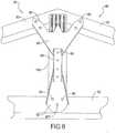
- the wind-beam system 80is a series of reinforcement components employed at the connections of rafters 50, 50' and trusses 52 to enhance the structural integrity of the rafters and trusses.
- a typical truss 52is enhanced at connection points 86, 88, 90 with wind-beam components including in several preferred embodiments a wind-beam chord connector 92, a wind-beam extension 94, and a wind-beam ridge connector 96.
- the wind-beam chord connector 92is a metal member connecting the joist 52 to an angularly oriented joining member, which according to several aspects is a transversely oriented center gable end stud or kingpost 100.
- the wind-beam ridge connector 96is a metal plate connecting the kingpost 100 to both of the upper chords or rafters 50, 50'.
- the wind-beam extension 94is a metal U-channel that can be used to connect the wind-beam chord connector 92 to the wind-beam ridge connector 96.
- Typical construction techniques for rafters 50 and trusses 52include nail plates and individual nails at connection points.
- the wind-beam system 80effectively reinforces roof rafters 52 and/or trusses 98 together with strong and securely fastened members such as the wind-beam chord connector 92, wind-beam extension 94, and wind-beam ridge connector 96, which effectively unitizes the entire roof system together to act more as a unit than as individual roof components.
- the wind-beam system 80works on traditional rafter systems and/or traditional truss systems. Those skilled in the art will appreciate that the steeper the roof pitch, the greater the lift forces on the leeward side, and thus the stronger the wind-beam system 80 effectively needs to be, all things being equal.
- the present disclosureeffectively unitizes the entire roof system by employing the features of the wind-beam system 80 to cooperate and integrate with the respective features of the rafter/joist tie-down system 66 and the roof decking system 82, the venting system 84, the diaphragm reinforcement system 70, and/or the safe room system 72.
- the wall sheeting system 68provides an improved method of covering and sealing the exterior walls 38 of the structure prior to applying additional façade or other cosmetic coverings such as vinyl siding, brick, et cetera.
- Wall sheeting 42such as plywood, is bolted to the wall reinforcement structural columns 18 using bolts 102.
- the wall sheeting system 68provides an improved fastening method by bolting the sheeting 42 to the wall reinforcement system 34, which ensures that the sheeting 42 will remain securely in place when the structure is exposed to storm wind forces.
- the wall sheeting system 68stays securely in place during storm wind forces, it is enabled to provide a secondary water seal for the wall 38 to resist rain and blowing rain in the event that the primary covering and weather seal façade is compromised and/or lost during storm winds subjected upon the structure.
- One preferred embodimentincludes a specialized bolted fastener 102 featuring an enlarged flat head 104 with barbs 106 which seat into the sheeting 42 and includes a sealing ring rib 108 on the underside 110 of the enlarged head 104 to securely and firmly hold and maintain a watertight seal.
- the wall sheeting system 68is incorporated into the safe room system 72 such that requirements for resisting penetrations from airborne debris are accomplished.
- the present disclosureeffectively unitizes the entire wall construction by employing the features of the wall sheeting system 68 to cooperate and integrate with the respective features of the wall reinforcement system 34 and a window/door protective seal system 112 (shown and described with respect to Figure 12 ), and the safe room system 72.
- bolted fastening methodsexist for attaching the sheeting to the structural column such as tapped holes in the structural column 18 to receive a bolt.
- Another bolted alternativeincludes the use of a standard nut clipped or attached to the structural column 18 to receive a bolt.
- a further bolted method for fastening the sheeting to the structural column 18includes any one of several self-tapping screws.
- Still another fastening methodincludes using a bracket that bolts to the sheeting and separately bolts to the structural column 18. Any of these bolted fastening methods will satisfy the spirit of securing the sheeting directly to the structural column.
- the bolted fastenersmay require a large head and/or a washer device to prevent the head of the fastener from pulling through the sheeting when storm wind forces are applied to the structure.
- the large head fastenersmay be standard carriage bolt type fasteners or other standard head bolts with washer devices to effectively enlarge the bearing surface of the head of the fastener.
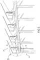
- the roof decking system 82provides an improved method of covering and sealing roof decking 114 such as sheets of plywood of the structure prior to applying additional façade or other cosmetic coverings such as shingles, metal, et cetera.
- a watertight tape seal 116 applied over seams 118 at mating edges of roof decking 114helps to provide a watertight seal.
- the roof decking system 82provides an improved fastening means via nails and/or screws and/or a specific patterned array application of the fasteners so as to securely retain the decking 114 attached to the rafters and/or joist structure.
- a specialized fastener 120has a relatively large head and specialized retention features so as to provide improved retention of the decking to the rafters and/or joist.
- Another preferred embodimentfeatures the decking 114 to be tongue & grooved so as to provide a watertight seal via interlaced edges of the decking.
- a further preferred embodiment of the decking 114features a shiplap edge 122 which presents a watertight sealed edge on a bias cut.
- Yet another preferred embodiment of the deckingincludes lineup blocking 124 between adjacent rafters 50, 50' and located under the edges 126 of adjacent decking 114 so as to provide a secure fastening surface for the entire edge 126 of the decking 114.
- the lineup blocking 124also provides an effective sealing surface under the edge of adjacent sheets of decking 114 and prevents relative deflection at the mating edges of adjacent sheets of decking.
- the lineup blocking 124also provides proper alignment and spacing between rafters 50, 50' while at the same time providing resistance to torsion and rhombus forces acting on the rafters and joist.
- the lineup blocking 124also defines a continuous line of compression blocks installed between juxtaposed rafters and/or joist to prevent lateral collapse of the structure.
- fastening methodsexist for attaching the roof decking to the rafters and/or truss elements.
- Another alternativeincludes the use of a standard screw type fastener.
- a further method for fastening the roof deckingincludes any one of several nails in specialized patterns.
- Still another fastening methodincludes using a specialized nail with spiral shapes upon it that in essence function like a screw that has been driven into place like a nail. Any of these fastening methods will satisfy the spirit of securing the roof decking directly to the rafters and/or truss roof elements.
- the fastenersmay require a large head and/or a washer device to prevent the head of the fastener from pulling through the decking when storm wind forces are applied to the structure.
- the large head fastenersmay be standard screw or nail type fasteners or other standard fasteners with washer devices to effectively enlarge the bearing surface of the head of the fastener.
- One preferred embodiment of the lineup blocking 124features a bracket 128 which can be either preassembled to the ends of the lineup block 124 or installed after the lineup block 124 is installed.
- the bracket 128provides additional ease of assembly and additional structural integrity to the rafters 50 and decking 114.
- Another preferred applicationemploys the respective features of a watertight membrane 130 placed over the decking 114 and/or the watertight seal tape 116 covering over the mating edges of adjacent sheets of decking 114, including ridges and valleys.
- a cross section through one preferred embodiment of the roof decking system 82shows shiplap edges, lineup blocks 124, lineup block brackets 128, decking fasteners 120, tapeseals 116 at joints, and the watertight membrane 130.
- the roof decking system 82provides a secondary water seal for the roof to resist rain and blowing rain in the event that the primary covering and weather seal façade is compromised and/or lost during storm winds subjected upon the structure.
- the present disclosureeffectively unitizes the entire roof construction by employing the roof decking system 82 to cooperate and integrate with the respective features of the wall reinforcement system 34, the wind beam system 80, the rafter/joist tie-down system 66, the roof decking system 82, the venting system 84, the diaphragm reinforcement system 70, and/or the safe room system 72.
- the diaphragm reinforcement system 70addresses several diaphragm problems commonly associated with residential and commercial construction.
- One common diaphragm problemis gable ends of construction wherein for instance a triangle shaped wall gable end 132 is formed enclosing one end of a roof system 134.
- the gable end 132forms a gable end plane 136 inside the triangle frame of the gable end 132 which is susceptible to being either blown in or sucked out in response to storm winds.
- Another common diaphragm problemis a joist plane 138 formed by any one of several rafter/joist/truss components such as joists 52 shown, juxtaposed in array adjacent to the gable end 132 of the roof construction.
- the joist plane 138is susceptible to being warped and/or wrenched and/or twisted and/or laterally shifted in response to storm wind forces.
- Yet another common diaphragm problemis a ceiling plane 140 formed by a ceiling 142 on the underside of the juxtaposed array of joists 52.
- the ceiling plane 140is susceptible to warping and flexing due to the joist plane 138 responding to storm winds acting on the structure.
- the present disclosureovercomes the problems associated with these diaphragms by employing the diaphragm reinforcement system 70.
- One preferred embodiment of the diaphragm reinforcement system 70features a pearling brace 144 spanning transverse across the gable end 132.
- the pearling brace 144in one preferred embodiment provides a series of specialized brackets 146 which cooperate with standard wood components to enhance the structural integrity of the gable end plane 136.
- a structural metal beam 148 and associated bracketsspan transversely across the gable end 132 to enhance the structural integrity of the gable end plane 136.
- diaphragm reinforcement system 70features a series of joist brace elements 150 spanning transversely across the array of juxtaposed joists 52 so as to enhance the structural integrity of the joist array to prevent them from being negatively affected by storm force winds.
- the joist brace elements 150are firmly affixed to the joist 52 such that the joist 52 is not only prevented from suffering detrimental joist plane 138 deformation but also preventing detrimental ceiling plane 140 deformation.
- the joist brace elements 150are firmly anchored to specialized gable end brackets 152 at the gable end 132 which in turn are directly anchored to the wall reinforcement system 34 components, which in turn anchor the entire construction to the foundation elements.
- the joist brace elements 150also include strut elements 154 attaching at one end to the joist brace elements 150 and then spanning at a bias angle ⁇ up to a connection point 156 on the pearling brace 144.
- the strut 154forms the hypotenuse of a triangle comprised of the strut 154, the gable end plane 136, and a joist brace 158 element, which subsequently forms an enhanced structural means to impart structural integrity to the diaphragms aforementioned.
- One or more joist brace brackets 160which connect the joist brace 158 to the joists 52 also define members of the joist brace elements 150.
- the gable end plane 136, the ceiling plane 140, and the joist plane 138are simultaneously structurally enhanced via the collective features of the gable end bracket 152, the joist brace bracket 160, the joist brace 158, the strut 154, and the pearling brace 144.
- the entire set of diaphragmsare effectively unitized together and integrated into a larger unitized system of structural integrity to maintain a watertight seal system for the construction when subjected to storm wind forces.
- the present disclosureeffectively unitizes the diaphragm reinforcement system 70 by employing and integrating the respective features of the anchoring system 10, the wall reinforcement system 34, the rafter/joist tie-down system 66, the wind-beam system 80, the wall sheeting system 68, the venting system 84, and/or the safe room system 72.
- an internal access vent 162enables air to pass from the conditioned air space defining a living portion 164 of the structure and slightly conditions the air in a roof space 166, wherein a closed cell spray foam 168 insulates and seals the entire underside of a roof system 170 and gable ends 132 to prevent water leaks.
- the venting system 84provides a solution for maintaining appropriate thermal conditions for the air in the roof space 166 of a structure so that appropriate air changes and/or conditioning occur in the roof space 166.
- Typical venting methodsinclude a series of external access vents, such as under eve soffit vents, gable vents, ridge vents, turbines, and louvers, many of which come in passive or powered variations.
- a significant problem that basically all known external access venting systems sufferis that they are susceptible to being damaged and/or completely removed during blowing rain in wind storm conditions, which lead to water leaks and subsequent damage.
- Another significant problem that basically all prior art external access venting systems sufferis that, even if they manage to stay intact during the wind storm conditions, they are further susceptible to allowing blowing rain in wind storm conditions to pass through them and into the roof space, which leads to water leaks and subsequent damage.
- venting system 84provides specialized external venting devices for influent and effluent air handling which are able to remain firmly and functionally intact and at the same time control and mitigate blowing rain during wind storm conditions such that water is channeled and/or redirected and/or drained back out of the structure, preventing damaging accumulation inside the structure.
- Another preferred embodiment of the subject inventioneliminates all external access vents so as to eliminate the problems with any such locations and/or associated venting devices, and replaces them with the small, appropriately sized internal access vents 162 directly connecting the conditioned portion of the structure to the roof space to slightly "condition" the air in the roof space. There is, therefore, no external access vents communicating between the internal conditioned portion of the building structure to ambient air outside the building structure.
- the conditioned air in the roof space 166is both appropriately cooled and/or heated in conjunction with the seasons of the year to maintain a moderate temperature range in the roof space 166.
- the conditioned air in the roof space 166is further enabled by having no influent or effluent outside air to influence the roof space 166; however, an efficient insulation sealing system, such as the closed cell spray foam 168, is applied to the entire underside of the roof construction to fill in between the rafters 50 to provide an air and water seal to prevent air and water from penetrating the roof construction into the roof space 166.
- the closed cell spray foam 168 insulationalso covers and seals any fasteners of the decking 114 or shingles 172 or other exterior construction that might have penetrated through the decking 114 and into the roof space 166, such that any chance of becoming a future leak path is prevented.
- the closed cell spray foam 168 insulationalso covers walls 174 of the gable ends 132 in the same manner.
- the present disclosureeffectively cooperates with a unitized roof construction by employing the venting system 84 to cooperate and integrate with the respective features of the roof decking system 82, the wind beam system 80, the rafter/joist tie-down system 66, and the diaphragm reinforcement system 70.
- one preferred embodiment of the window/door protective system 112provides for a typical widow 176 for residential structures which is fitted with installed decorative cover mounts 178 such that a removable protective cover 180 securely fastens to the cover mounts 178.
- the window/door protective system 112provides the protective cover 180 over windows 176 to minimize the likelihood of breakage during wind storms.
- One preferred embodiment of the window/door protective system 112is comprised of a series of brackets 182 and mounting hardware designed to securely establish a robust attachment to the structure 184 and receives an appropriate protective cover 180 designed to fit into and cooperate with the mounted protective cover brackets 182.
- the protective covers 180can be stored until required to prepare for an oncoming wind storm.
- the mounted brackets 182will remain mounted to the structure 184 and designed to be reasonably decorative.
- Another preferred embodimentfeatures a similar protective cover 186 over doors 188 and/or installed inside of exterior doors to prevent them from blowing in or being sucked outward during storm winds.
- Another preferred embodimentfeatures a protective cover over garage doors (not shown) to prevent them from blowing in or being sucked outward during storm winds.
- the present disclosureemploys the window/door protective system 112 to cooperate and integrate with the respective features of the wall reinforcement system 34 and/or the safe room system 72.
- a preferred embodiment of the storm safe room 72provides an independent unitized room 190 constructed and fitted with a storm door 192 and an air vent 194 positioned inside the building structure.
- Another preferred embodimentfeatures a storm safe room system 72 which is prefabricated from appropriate enhanced components and delivered to the construction site, and then installed so the building 196 can be constructed around it.
- the storm safe room system 72provides enhanced construction components for a self-contained storm safe room which is firmly and strongly anchored to the foundation and/or slab of the structure.
- the enhanced construction componentsinclude those featured in the wall reinforcement system 34, the anchor system 10, the rafter-joist tie-down system 66, the wind beam system 80, door/window protective seal system 112, and/or the roof decking system 82, all combined together to establish a unitized structure to function as an appropriate storm safe room system 72.
- the storm safe room system 72includes an independent unitized roof 198, reinforced walls 200, and the storm door 192 which opens inward.
- the doorfeatures enhanced hinges 202 and locking and security components 204 to ensure closure in the event it is subjected to storm force winds, flying debris, and/or influent water.
- the storm safe room system 72provides the independent fresh air vent 194 and the reinforced door 192 to prevent it from opening except at the command of the occupant and provides a watertight seal 206 to prevent influent water.
- the storm safe room system 72provides a storm room suitable of being used as a dual purpose room, such as a closet, pantry, bathroom, or the like.
- One preferred embodimentfeatures a storm safe room system 72 constructed on-site using appropriate enhanced components.
- the present disclosureeffectively establishes a unitized storm safe room system 72 by cooperating and integrating with the respective features of the anchor system 10, the wall reinforcement system 34, the rafter/joist tie-down system 66, the window/door protective seal system 112, the roof decking system 82, the venting system 84, the wind-beam system 80, the diaphragm reinforcement system 70, and the wall sheeting system 68.
- the present disclosureprovides an improved system for a typical residential or commercial structure wherein a series of specialized components are integrated together so as to enhance the structural integrity of the structure against wind forces, such as those associated with hurricanes and/or tornados, so as to provide a secondary relatively watertight seal for the structure, even in the event that the primary sealing system of shingles and/or siding is compromised, damaged, or removed by the storm winds.
- known shingles and sidingprovide a cosmetic covering and a primary water seal for the structure; however, the present disclosure provides a secondary water seal in the event that the primary seal system is compromised during storm wind exposure.
- the present disclosurefurther provides structural enhancements that can be applied to new construction as well as retrofitting existing structures so as to improve structural integrity and secondary sealing against wind forces such as those associated with hurricanes and/or tornados.
- the present disclosurefurther provides structural enhancements that cooperate with standard construction components so as to improve the structural integrity of the construction components beyond their original capabilities against wind forces, such as those associated with hurricanes and/or tornados, and further to provide a secondary sealing system to resist influent water in the event that the primary sealing system is compromised.
- the typical preferred embodiment construction material for the structural enhanced components of the present disclosureis metal.
- the componentsmay be manufactured from metal using any one of several typical methods such as stamping, forging, bending, welding, or combinations of fabrication methods.
- the componentsmay be manufactured from non-metal materials such as plastic, reinforced plastic, fiberglass, composites, and/or any other appropriate technology materials suitable to provide the strength requirements for a given application.
Landscapes
- Engineering & Computer Science (AREA)
- Architecture (AREA)
- Structural Engineering (AREA)
- Civil Engineering (AREA)
- Electromagnetism (AREA)
- Physics & Mathematics (AREA)
- Environmental & Geological Engineering (AREA)
- Business, Economics & Management (AREA)
- Emergency Management (AREA)
- Life Sciences & Earth Sciences (AREA)
- Pest Control & Pesticides (AREA)
- Building Environments (AREA)
- Roof Covering Using Slabs Or Stiff Sheets (AREA)
- Working Measures On Existing Buildindgs (AREA)
Description
- The present disclosure relates to storm resistant components and residential or commercial structures enhanced to survive storm winds and rain.
- This section provides background information related to the present disclosure which is not necessarily prior art.
- It is well known that hurricanes and tornados create storm wind forces capable of damaging and/or destroying standard residential and commercial constructions. Wind storm forces are known to remove and/or compromise the primary sealing systems of shingles, roofing, siding, and veneers. Furthermore, wind storm forces are well known to lift off entire roof systems and blow down and/or suck out walls.
- In addition, wind storm forces are well known to impose substantial blowing rain events which become influent to structures even before the construction components fail and/or are compromised. Beyond the obvious influent opportunities resulting from broken windows and/or other compromised construction components, wind storm events are known to blow rain into and through functioning vents of an intact roof system, thus creating water damage even though little or no actual structural damage occurs.
- There are numerous representatives of known art resident in the patent records that deal with various hurricane or tornado storm wind forces by claiming use of any one of several strengthening components. However, one of the major problems with all of the known examples is that they do not lend themselves to our do-it-yourself culture and do not lend themselves to be cost effective for the mass consumption public at large.
- Another problem with known art examples is that none of these patent records for structural strengthening systems includes a means to provide a secondary sealing system for the structure in the event the primary sealing system of shingles and/or siding of the structure are compromised.
- There are some references of known art in the patent records related to systems that minimize water influent damage from wind storms, but once again, none of these examples lend themselves to our do-it-yourself culture and do not lend themselves to be cost effective for the mass consumption public at large. In addition, none of the known examples provide any strengthening enhancements to improve the structural integrity of the construction. Furthermore, none of these prior art sealing systems provides a secondary sealing system in the event that the primary sealing system is compromised.
- From
US 2006/0254167 A1 a structural support framing assembly for use in residential, commercial, and industrial building construction is known, in which a variety of profiles and support beams are connected to form a frame structure. The single support beams are connected on one side via anchors with a base plate or foundation, respectively. - From
WO 2008/007325 A2 a construction of a building is known in which several wooden beams are connected with each other with the help of metal components. This document discloses all the features of the preamble ofclaim 1. - One preferred embodiment of the present disclosure relates to a typical residential stick-built or prefabricated home construction which is enhanced and substantially strengthened in specific areas of the structure to better withstand the destructive wind forces of hurricanes and tornados. One preferred embodiment also provides a secondary watertight seal which is utilized to maintain a reasonable barrier from influent storm water and blowing rain in the event that the primary water barrier via the shingles and/or siding is compromised during the storm.
- It is understood that the secondary water seal requires that the structure must maintain a reasonable structural integrity; therefore, a series of structural enhancements are employed for this purpose and to further maintain structure integrity against storm wind forces. The structural enhancement system is comprised of several subsystems which all work together to collectively enhance the structural integrity of the structure. These subsystems include but are not limited to the following:
- Anchoring System Having Anchor Fasteners
- Wall Reinforcement System
- Rafter/Joist Tie-Down System
- Wind-Beam System
- Diaphragm Reinforcement System
- Wall Sheeting System
- Roof Decking System
- Venting System
- Window/Door Protective Seal System
- Safe Room System
- Those skilled in the art will readily understand that while many typical structures will require all of the listed subsystems to enhance the structure adequately against storm winds, some complex structures may require additional specialized subsystems, while less complex structures may only require a partial list of the subsystems. A brief description of each subsystem follows.
- Further areas of applicability will become apparent from the description provided herein. The description and specific examples in this summary are intended for purposes of illustration only and are not intended to limit the scope of the present disclosure.
- The drawings described herein are for illustrative purposes only of selected embodiments and not all possible implementations, and are not intended to limit the scope of the present disclosure.
Figure 1 is a front left perspective view of a building structure anchoring system;Figure 2 is a front left perspective view of the building structure ofFigure 1 , further including a wall reinforcement system;Figure 3 is a front left perspective view ofarea 3 ofFigure 2 ;Figure 4 is a front left perspective view of a portion of the building structure ofFigure 1 , modified to show upper and lower structure joined by floor joists;Figure 5 is a front right perspective view ofarea 5 ofFigure 3 ;Figure 6 is a bottom front perspective view of a truss assembly;Figure 7 is a front left perspective view of the building structure similar toFigure 2 , further including a wall sheeting system;Figure 8 is a front left perspective view of a roof decking system;Figure 9 is a front elevational view of the roof decking system ofFigure 8 ;Figure 10 is a cross sectional end elevational view taken atsection 10 ofFigure 9 ;Figure 11 is a cross sectional end elevational view modified fromFigure 10 to show a venting system;Figure 12 is a front elevational schematic view of a building window/door protective seal system; andFigure 13 is a front left perspective view of the building ofFigure 12 modified to include an interior storm safe room.- Corresponding reference numerals indicate corresponding parts throughout the several views of the drawings.
- Example embodiments will now be described more fully with reference to the accompanying drawings.
- Referring to
Figure 1 , ananchoring system 10 connected to atypical slab 12 defining a foundation construction includesanchor bolt sets 14 at least partially embedded in theslab 12 connected to a wall reinforcement system havingmultiple anchor brackets 16, and multiple specialized structural members orstructural columns 18 connected to theanchor brackets 16. Theanchoring system 10 havinganchor fasteners building structure 20 to theslab 12 or other foundational elements. One preferred embodiment enhancement system provides specialized first andsecond anchor bolts specialized anchor bolts anchor bolt nuts portions specialized anchor bolts anchor brackets 16, which are positioned between sequentially spaced apart members such asstuds new construction slabs 12 being poured, preexisting slabs, and for construction or retrofit of structures on top of crawl space walls or basement walls. The freely extendingportions anchor bolts anchor bracket 16 are oppositely positioned with respect to alongitudinal axis 27 of thestructural column 18 connected to eachanchor bracket 16 to resist axial rotation/twisting of thestructural columns 18 and thereby to resist axial rotation/twisting of thestuds anchoring system 10 to cooperate and integrate the respective features of a wall reinforcement system 34 (shown and described in reference toFigures 2-3 ) and/or a safe room system 72 (shown and described in reference toFigure 13 ). - Referring to
Figure 2 and again toFigure 1 , thewall reinforcement system 34 is a subsystem which integrates into a typical studtype wall construction 36 ofbuilding structure 20 to provide significant enhanced compression and tension strength to thewall construction 36. A typical wood or metal stud builtwall 38 having sequentially spacedstuds
In addition, thewall reinforcement system 34 of the subject invention provides resistance to forces that result in torsion and/or rhombus conditions. The specialized structural member orstructural column 18 is a metal tube installed in thestud wall 38 at intervals between adjacent ones of the studs along thewall 38 and/or atwall corners 40 such that thestructural column 18 is substantially stronger than the typical stud wall components, such as wood or metal studs, and is capable of being firmly and strongly attached to theanchoring system 10 described in reference toFigure 1 . According to oneembodiment sheeting 42 is bolted to the specializedstructural column 18 which is anchored to thefoundation slab 12 and bolted through a doubletop plate 44 to the rafter/joist tie-down system 46. Thewall reinforcement system 34 provides a strong and solid connection from abottom plate 48 of thestud wall 38 all the way to thetop plate 44 of thestud wall 38, where it is again firmly and solidly attached and terminated. - Referring to
Figure 3 and again toFigures 1-2 , according to one embodiment, thestructural column 18 is bolted through thetop plate 44 of thewall 38 toroof elements wall reinforcement system 34 ties together the roof components, the wall components, and the foundation using thestructural columns 18 fastened/bolted at opposite ends to building structure. - Referring to
Figure 4 and again toFigures 1-3 , the present disclosure also applies to multi-story structures by employing bolted connections across afloor joist construction 54 of amulti-story wall construction 56 whereinwall reinforcement columns 18, 18' on lower andupper floors connectors floor joist construction 54. The present disclosure effectively unitizes theentire wall construction 56 by employing thewall reinforcement system 34 to cooperate and integrate the respective features of theanchoring system 10 and a rafter/joist tie-down system 66 (which is shown and described in reference toFigure 5 ) and with a wall sheeting system 68 (which is shown and described in reference toFigure 7 ) and with a diaphragm reinforcement system 70 (which is shown and described in reference toFigure 10 ) and/or a safe room system 72 (which is shown and described in reference toFigure 13 ). - Referring to
Figure 5 and again toFigures 1-4 , the rafter/joist tie-down system 66 is a firmly and strongly attached means to effectively connect the upper chords orrafters 50 and the lower chords orceiling joists 52 to thetop plate 44 of thestud wall 38 and more importantly directly to thewall reinforcement system 34. The rafter/joist tie-down system 66 also provides a strong connection means at each crossing point on outside walls and inside walls, for everyrafter 50 and/orjoist 52 whether it is connected directly to or indirectly connected to amember 18 of thewall reinforcement system 34. - Referring to
Figure 5 , each wall reinforcement member orstructural column 18 is bolted to a rafter tie-down connector 74. A typical truss example is provided wherein a rafter tie-down extension 76 spans between thelower chord 52 andupper chord 50 of atruss 78. The rafter/joist tie-down system 66 also resistsrafters 50 and/orjoists 52 from being compromised due to lift forces generated by storm wind forces. The rafter/joist tie-down system 66 also resistsrafters 50 and/orjoists 52 from being easily twisted due to torsion forces and/or rhombus forces which enhances the relative strength of the structure to resist shear forces acting upon the structure as a result of strong straight line winds or tornadic vortexes. Testing and research has demonstrated and taught that the best roof pitch for storm wind resistance is about a 15 degree angle off a horizontal plane, and that a hip roof construction is more storm-worthy than a gable end construction, and further that less roof overhang is better than long extended roof overhang construction. - The rafter/joist tie-
down system 66 is able to enhance standard roof construction that exploits the known research and yet still provides some enhancements for other roof constructions that do not conform to the prior art research for best storm construction. The present disclosure effectively unitizes the entire roof system by employing the features of the rafter/joist tie-down system 66 to cooperate and integrate with the respective features of thewall reinforcement system 34 and a wind-beam system 80 (shown and described in reference toFigure 6 ), a roof decking system 82 (shown and described in reference toFigure 8 ), a venting system 84 (shown and described in reference toFigure 11 ), thediaphragm reinforcement system 70, and/or thesafe room system 72. - Referring to
Figure 6 , the wind-beam system 80 is a series of reinforcement components employed at the connections ofrafters typical truss 52 is enhanced at connection points 86, 88, 90 with wind-beam components including in several preferred embodiments a wind-beam chord connector 92, a wind-beam extension 94, and a wind-beam ridge connector 96. The wind-beam chord connector 92 is a metal member connecting thejoist 52 to an angularly oriented joining member, which according to several aspects is a transversely oriented center gable end stud orkingpost 100. The wind-beam ridge connector 96 is a metal plate connecting thekingpost 100 to both of the upper chords orrafters beam extension 94 is a metal U-channel that can be used to connect the wind-beam chord connector 92 to the wind-beam ridge connector 96. Typical construction techniques forrafters 50 and trusses 52 include nail plates and individual nails at connection points. During storm wind conditions, one side of the roof is considered the windward side if the wind is blowing directly toward that roof section. As a result, the forces acting upon the roof place it compression. In contrast, the opposite side of the roof is referred to the leeward side and creates lifting force acting on this portion of the roof. As a result, the combination of one side of the roof pressing down simultaneously as the other side is trying to lift off invites significant structural damage at relatively low force values. - The wind-
beam system 80 effectively reinforcesroof rafters 52 and/or trusses 98 together with strong and securely fastened members such as the wind-beam chord connector 92, wind-beam extension 94, and wind-beam ridge connector 96, which effectively unitizes the entire roof system together to act more as a unit than as individual roof components. The wind-beam system 80 works on traditional rafter systems and/or traditional truss systems. Those skilled in the art will appreciate that the steeper the roof pitch, the greater the lift forces on the leeward side, and thus the stronger the wind-beam system 80 effectively needs to be, all things being equal. The present disclosure effectively unitizes the entire roof system by employing the features of the wind-beam system 80 to cooperate and integrate with the respective features of the rafter/joist tie-down system 66 and theroof decking system 82, the ventingsystem 84, thediaphragm reinforcement system 70, and/or thesafe room system 72. - Referring to
Figure 7 and again toFigures 1-6 , thewall sheeting system 68 provides an improved method of covering and sealing theexterior walls 38 of the structure prior to applying additional façade or other cosmetic coverings such as vinyl siding, brick, et cetera.Wall sheeting 42, such as plywood, is bolted to the wall reinforcementstructural columns 18 usingbolts 102. Thewall sheeting system 68 provides an improved fastening method by bolting thesheeting 42 to thewall reinforcement system 34, which ensures that thesheeting 42 will remain securely in place when the structure is exposed to storm wind forces. Because thewall sheeting system 68 stays securely in place during storm wind forces, it is enabled to provide a secondary water seal for thewall 38 to resist rain and blowing rain in the event that the primary covering and weather seal façade is compromised and/or lost during storm winds subjected upon the structure. One preferred embodiment includes a specialized boltedfastener 102 featuring an enlargedflat head 104 withbarbs 106 which seat into thesheeting 42 and includes a sealingring rib 108 on theunderside 110 of theenlarged head 104 to securely and firmly hold and maintain a watertight seal. In appropriate applications, thewall sheeting system 68 is incorporated into thesafe room system 72 such that requirements for resisting penetrations from airborne debris are accomplished. The present disclosure effectively unitizes the entire wall construction by employing the features of thewall sheeting system 68 to cooperate and integrate with the respective features of thewall reinforcement system 34 and a window/door protective seal system 112 (shown and described with respect toFigure 12 ), and thesafe room system 72. - Those skilled in the art will also recognize that alternative bolted fastening methods exist for attaching the sheeting to the structural column such as tapped holes in the
structural column 18 to receive a bolt. Another bolted alternative includes the use of a standard nut clipped or attached to thestructural column 18 to receive a bolt. A further bolted method for fastening the sheeting to thestructural column 18 includes any one of several self-tapping screws. Still another fastening method includes using a bracket that bolts to the sheeting and separately bolts to thestructural column 18. Any of these bolted fastening methods will satisfy the spirit of securing the sheeting directly to the structural column. It will also be appreciated that the bolted fasteners may require a large head and/or a washer device to prevent the head of the fastener from pulling through the sheeting when storm wind forces are applied to the structure. The large head fasteners may be standard carriage bolt type fasteners or other standard head bolts with washer devices to effectively enlarge the bearing surface of the head of the fastener. - Referring to
Figure 8 and again toFigures 1-3 , theroof decking system 82 provides an improved method of covering and sealingroof decking 114 such as sheets of plywood of the structure prior to applying additional façade or other cosmetic coverings such as shingles, metal, et cetera. Awatertight tape seal 116 applied overseams 118 at mating edges ofroof decking 114 helps to provide a watertight seal. Theroof decking system 82 provides an improved fastening means via nails and/or screws and/or a specific patterned array application of the fasteners so as to securely retain thedecking 114 attached to the rafters and/or joist structure. - Referring to
Figure 9 and again toFigures 1-3 and8 , aspecialized fastener 120 has a relatively large head and specialized retention features so as to provide improved retention of the decking to the rafters and/or joist. Another preferred embodiment features thedecking 114 to be tongue & grooved so as to provide a watertight seal via interlaced edges of the decking. A further preferred embodiment of thedecking 114 features ashiplap edge 122 which presents a watertight sealed edge on a bias cut. Yet another preferred embodiment of the decking includes lineup blocking 124 betweenadjacent rafters edges 126 ofadjacent decking 114 so as to provide a secure fastening surface for theentire edge 126 of thedecking 114. The lineup blocking 124 also provides an effective sealing surface under the edge of adjacent sheets ofdecking 114 and prevents relative deflection at the mating edges of adjacent sheets of decking. The lineup blocking 124 also provides proper alignment and spacing betweenrafters - Those skilled in the art will also recognize that alternative fastening methods exist for attaching the roof decking to the rafters and/or truss elements. Another alternative includes the use of a standard screw type fastener. A further method for fastening the roof decking includes any one of several nails in specialized patterns. Still another fastening method includes using a specialized nail with spiral shapes upon it that in essence function like a screw that has been driven into place like a nail. Any of these fastening methods will satisfy the spirit of securing the roof decking directly to the rafters and/or truss roof elements. It will also be appreciated that the fasteners may require a large head and/or a washer device to prevent the head of the fastener from pulling through the decking when storm wind forces are applied to the structure. The large head fasteners may be standard screw or nail type fasteners or other standard fasteners with washer devices to effectively enlarge the bearing surface of the head of the fastener.
- One preferred embodiment of the lineup blocking 124 features a
bracket 128 which can be either preassembled to the ends of the lineup block 124 or installed after thelineup block 124 is installed. Thebracket 128 provides additional ease of assembly and additional structural integrity to therafters 50 anddecking 114. Another preferred application employs the respective features of awatertight membrane 130 placed over thedecking 114 and/or thewatertight seal tape 116 covering over the mating edges of adjacent sheets ofdecking 114, including ridges and valleys. - Referring to
Figure 9 and again toFigures 1-8 , a cross section through one preferred embodiment of theroof decking system 82 shows shiplap edges, lineup blocks 124,lineup block brackets 128,decking fasteners 120, tapeseals 116 at joints, and thewatertight membrane 130. Theroof decking system 82 provides a secondary water seal for the roof to resist rain and blowing rain in the event that the primary covering and weather seal façade is compromised and/or lost during storm winds subjected upon the structure. The present disclosure effectively unitizes the entire roof construction by employing theroof decking system 82 to cooperate and integrate with the respective features of thewall reinforcement system 34, thewind beam system 80, the rafter/joist tie-down system 66, theroof decking system 82, the ventingsystem 84, thediaphragm reinforcement system 70, and/or thesafe room system 72. - Referring to
Figure 10 , thediaphragm reinforcement system 70 addresses several diaphragm problems commonly associated with residential and commercial construction. One common diaphragm problem is gable ends of construction wherein for instance a triangle shapedwall gable end 132 is formed enclosing one end of aroof system 134. Thegable end 132 forms agable end plane 136 inside the triangle frame of thegable end 132 which is susceptible to being either blown in or sucked out in response to storm winds. Another common diaphragm problem is ajoist plane 138 formed by any one of several rafter/joist/truss components such asjoists 52 shown, juxtaposed in array adjacent to thegable end 132 of the roof construction. Thejoist plane 138 is susceptible to being warped and/or wrenched and/or twisted and/or laterally shifted in response to storm wind forces. Yet another common diaphragm problem is aceiling plane 140 formed by aceiling 142 on the underside of the juxtaposed array ofjoists 52. Theceiling plane 140 is susceptible to warping and flexing due to thejoist plane 138 responding to storm winds acting on the structure. - The present disclosure overcomes the problems associated with these diaphragms by employing the
diaphragm reinforcement system 70. One preferred embodiment of thediaphragm reinforcement system 70 features apearling brace 144 spanning transverse across thegable end 132. Thepearling brace 144 in one preferred embodiment provides a series ofspecialized brackets 146 which cooperate with standard wood components to enhance the structural integrity of thegable end plane 136. In another preferred pearling embodiment, astructural metal beam 148 and associated brackets span transversely across thegable end 132 to enhance the structural integrity of thegable end plane 136. Another preferred embodiment of thediaphragm reinforcement system 70 features a series ofjoist brace elements 150 spanning transversely across the array of juxtaposedjoists 52 so as to enhance the structural integrity of the joist array to prevent them from being negatively affected by storm force winds. - The
joist brace elements 150 are firmly affixed to thejoist 52 such that thejoist 52 is not only prevented from sufferingdetrimental joist plane 138 deformation but also preventingdetrimental ceiling plane 140 deformation. Thejoist brace elements 150 are firmly anchored to specializedgable end brackets 152 at thegable end 132 which in turn are directly anchored to thewall reinforcement system 34 components, which in turn anchor the entire construction to the foundation elements. Thejoist brace elements 150 also includestrut elements 154 attaching at one end to thejoist brace elements 150 and then spanning at a bias angle α up to aconnection point 156 on thepearling brace 144. Thestrut 154 forms the hypotenuse of a triangle comprised of thestrut 154, thegable end plane 136, and ajoist brace 158 element, which subsequently forms an enhanced structural means to impart structural integrity to the diaphragms aforementioned. One or morejoist brace brackets 160 which connect thejoist brace 158 to thejoists 52 also define members of thejoist brace elements 150. - With continuing reference to
Figure 10 , thegable end plane 136, theceiling plane 140, and thejoist plane 138 are simultaneously structurally enhanced via the collective features of thegable end bracket 152, thejoist brace bracket 160, thejoist brace 158, thestrut 154, and thepearling brace 144. As a result, the entire set of diaphragms are effectively unitized together and integrated into a larger unitized system of structural integrity to maintain a watertight seal system for the construction when subjected to storm wind forces. The present disclosure effectively unitizes thediaphragm reinforcement system 70 by employing and integrating the respective features of theanchoring system 10, thewall reinforcement system 34, the rafter/joist tie-down system 66, the wind-beam system 80, thewall sheeting system 68, the ventingsystem 84, and/or thesafe room system 72. - Referring to
Figure 11 , according to one preferred embodiment of theventing system 84, aninternal access vent 162 enables air to pass from the conditioned air space defining a livingportion 164 of the structure and slightly conditions the air in aroof space 166, wherein a closedcell spray foam 168 insulates and seals the entire underside of aroof system 170 and gable ends 132 to prevent water leaks. The ventingsystem 84 provides a solution for maintaining appropriate thermal conditions for the air in theroof space 166 of a structure so that appropriate air changes and/or conditioning occur in theroof space 166. Typical venting methods include a series of external access vents, such as under eve soffit vents, gable vents, ridge vents, turbines, and louvers, many of which come in passive or powered variations. - A significant problem that basically all known external access venting systems suffer is that they are susceptible to being damaged and/or completely removed during blowing rain in wind storm conditions, which lead to water leaks and subsequent damage. Another significant problem that basically all prior art external access venting systems suffer is that, even if they manage to stay intact during the wind storm conditions, they are further susceptible to allowing blowing rain in wind storm conditions to pass through them and into the roof space, which leads to water leaks and subsequent damage. Therefore, one preferred embodiment of the
venting system 84 provides specialized external venting devices for influent and effluent air handling which are able to remain firmly and functionally intact and at the same time control and mitigate blowing rain during wind storm conditions such that water is channeled and/or redirected and/or drained back out of the structure, preventing damaging accumulation inside the structure. - Another preferred embodiment of the subject invention eliminates all external access vents so as to eliminate the problems with any such locations and/or associated venting devices, and replaces them with the small, appropriately sized internal access vents 162 directly connecting the conditioned portion of the structure to the roof space to slightly "condition" the air in the roof space. There is, therefore, no external access vents communicating between the internal conditioned portion of the building structure to ambient air outside the building structure. The conditioned air in the
roof space 166 is both appropriately cooled and/or heated in conjunction with the seasons of the year to maintain a moderate temperature range in theroof space 166. The conditioned air in theroof space 166 is further enabled by having no influent or effluent outside air to influence theroof space 166; however, an efficient insulation sealing system, such as the closedcell spray foam 168, is applied to the entire underside of the roof construction to fill in between therafters 50 to provide an air and water seal to prevent air and water from penetrating the roof construction into theroof space 166. The closedcell spray foam 168 insulation also covers and seals any fasteners of thedecking 114 orshingles 172 or other exterior construction that might have penetrated through thedecking 114 and into theroof space 166, such that any chance of becoming a future leak path is prevented. The closedcell spray foam 168 insulation also coverswalls 174 of the gable ends 132 in the same manner. The present disclosure effectively cooperates with a unitized roof construction by employing theventing system 84 to cooperate and integrate with the respective features of theroof decking system 82, thewind beam system 80, the rafter/joist tie-down system 66, and thediaphragm reinforcement system 70. - Referring to
Figure 12 , one preferred embodiment of the window/doorprotective system 112 provides for atypical widow 176 for residential structures which is fitted with installed decorative cover mounts 178 such that a removableprotective cover 180 securely fastens to the cover mounts 178. The window/doorprotective system 112 provides theprotective cover 180 overwindows 176 to minimize the likelihood of breakage during wind storms. One preferred embodiment of the window/doorprotective system 112 is comprised of a series ofbrackets 182 and mounting hardware designed to securely establish a robust attachment to thestructure 184 and receives an appropriateprotective cover 180 designed to fit into and cooperate with the mountedprotective cover brackets 182. The protective covers 180 can be stored until required to prepare for an oncoming wind storm. The mountedbrackets 182 will remain mounted to thestructure 184 and designed to be reasonably decorative. Another preferred embodiment features a similarprotective cover 186 overdoors 188 and/or installed inside of exterior doors to prevent them from blowing in or being sucked outward during storm winds. Another preferred embodiment features a protective cover over garage doors (not shown) to prevent them from blowing in or being sucked outward during storm winds. The present disclosure employs the window/doorprotective system 112 to cooperate and integrate with the respective features of thewall reinforcement system 34 and/or thesafe room system 72. - Referring to
Figure 13 , a preferred embodiment of the stormsafe room 72 provides an independentunitized room 190 constructed and fitted with astorm door 192 and anair vent 194 positioned inside the building structure. Another preferred embodiment features a stormsafe room system 72 which is prefabricated from appropriate enhanced components and delivered to the construction site, and then installed so thebuilding 196 can be constructed around it. The stormsafe room system 72 provides enhanced construction components for a self-contained storm safe room which is firmly and strongly anchored to the foundation and/or slab of the structure. The enhanced construction components include those featured in thewall reinforcement system 34, theanchor system 10, the rafter-joist tie-down system 66, thewind beam system 80, door/windowprotective seal system 112, and/or theroof decking system 82, all combined together to establish a unitized structure to function as an appropriate stormsafe room system 72. - Another preferred embodiment of the storm
safe room system 72 includes an independentunitized roof 198, reinforcedwalls 200, and thestorm door 192 which opens inward. The door featuresenhanced hinges 202 and locking andsecurity components 204 to ensure closure in the event it is subjected to storm force winds, flying debris, and/or influent water. The stormsafe room system 72 provides the independentfresh air vent 194 and the reinforceddoor 192 to prevent it from opening except at the command of the occupant and provides awatertight seal 206 to prevent influent water. The stormsafe room system 72 provides a storm room suitable of being used as a dual purpose room, such as a closet, pantry, bathroom, or the like. One preferred embodiment features a stormsafe room system 72 constructed on-site using appropriate enhanced components. - The present disclosure effectively establishes a unitized storm
safe room system 72 by cooperating and integrating with the respective features of theanchor system 10, thewall reinforcement system 34, the rafter/joist tie-down system 66, the window/doorprotective seal system 112, theroof decking system 82, the ventingsystem 84, the wind-beam system 80, thediaphragm reinforcement system 70, and thewall sheeting system 68. - The present disclosure provides an improved system for a typical residential or commercial structure wherein a series of specialized components are integrated together so as to enhance the structural integrity of the structure against wind forces, such as those associated with hurricanes and/or tornados, so as to provide a secondary relatively watertight seal for the structure, even in the event that the primary sealing system of shingles and/or siding is compromised, damaged, or removed by the storm winds. As a result, known shingles and siding provide a cosmetic covering and a primary water seal for the structure; however, the present disclosure provides a secondary water seal in the event that the primary seal system is compromised during storm wind exposure.
- The present disclosure further provides structural enhancements that can be applied to new construction as well as retrofitting existing structures so as to improve structural integrity and secondary sealing against wind forces such as those associated with hurricanes and/or tornados. The present disclosure further provides structural enhancements that cooperate with standard construction components so as to improve the structural integrity of the construction components beyond their original capabilities against wind forces, such as those associated with hurricanes and/or tornados, and further to provide a secondary sealing system to resist influent water in the event that the primary sealing system is compromised.
- The typical preferred embodiment construction material for the structural enhanced components of the present disclosure is metal. The components may be manufactured from metal using any one of several typical methods such as stamping, forging, bending, welding, or combinations of fabrication methods. In addition, the components may be manufactured from non-metal materials such as plastic, reinforced plastic, fiberglass, composites, and/or any other appropriate technology materials suitable to provide the strength requirements for a given application.
Claims (12)
- A construction system providing structural integrity for a building structure to withstand the destructive forces of storm winds and to minimize or prevent the influent of associated wind-driven blowing rain, comprising:said building structure, andmultiple subsystems (10, 34, 46, 66, 68, 70, 72, 80, 82, 84, 112) connected to the building structure (20), the building structure (20) including a wall structure (36) having multiple studs (30, 32) and a roof structure having multiple components including trusses (52) or a combination of joists (52) and rafters (50, 50'),the multiple subsystems include:an anchoring system (10) having multiple anchor fasteners (22, 24) partly embedded in a foundation (12) and having portions (22a, 24a) of the anchor fasteners (22, 24) extending out of the foundation (12);a wall reinforcement system (34) having multiple structural columns (18) individually positioned between proximate ones of the studs (30, 32), the portion of the anchor fasteners (22, 24) connected to the structural columns (18) and the structural columns (18) oppositely connected to the roof structure such that the wall reinforcement system (34) ties together the roof components and the wall structure (36) to the foundation (12) using the structural columns (18);characterized in thatthe multiple anchor fasteners (22, 24) are sets of two anchor fasteners (22, 24), and the portions (22a, 24a) of the two anchor fasteners (22, 24) are both connected to one structural column (18);andin that the multiple subsystems further include:a wind-beam system (80) having:a wind-beam chord connector (92) connected to a joist (52) and to a kingpost (100) extending transversely from the joist (52);a wind-beam ridge connector (96) connected to adjoining first and second rafters (50, 50') and to the kingpost (100); anda wind-beam extension (94) connecting the wind-beam chord connector (92) to the wind-beam ridge connector (96).
- The construction system of Claim 1, wherein the multiple subsystems further include a wall sheeting system (68) having wall sheeting (42) bolted to multiple ones of the structural columns (18).
- The construction system of Claim 1, wherein the multiple subsystems further include a roof decking system (82) having a water resistant tape seal (116) applied at each joint defined between adjacent ones of a plurality of roof decking members (114) attached to the roof structure.
- The construction system of Claim 1, wherein the multiple subsystems further include a diaphragm reinforcement system (70) having a joist brace (150) connected to multiple ones of the joists (50, 52), a strut (154) angularly oriented with respect to the joist brace (150), and a pearling brace (144) connecting the strut (154) to a gable end (132) of the building structure (20).
- The construction system of Claim 1, wherein the multiple subsystems further include a venting system (84) having:no external access vents communicating between a living portion (164) of the building structure (20) to ambient air outside the building structure (20); andan internal access vent (162) directly connecting a conditioned portion of the living portion t (164) o a roof space (166) to condition the air in the roof space (166).
- The construction system of Claim 1, wherein the multiple subsystems further include a window/door protective seal system (112) having:a removable protective cover (180) applied to a window of the building structure (20); anda series of cover brackets (182) and mounting hardware providing for attachment to the building structure (20) receiving the protective cover (180), thereby fitting into and cooperating with the cover brackets (182).
- The construction system of Claim 6, wherein the window/door protective seal system (112) further includes a protective cover (186) provided over or inside of an exterior door (184) acting to prevent the exterior door (184) from blowing in or being sucked outward.
- The construction system of Claim 1, wherein the multiple subsystems further include a storm safe room system (72) defining an independent unitized room constructed and fitted with a storm door (192) and an air vent (194), the unitized room positioned inside the building structure.
- The construction system of Claim 8, wherein the storm door (192) further includes locking and security components (204), to ensure closure in the event the storm door (192) is subjected to storm force winds, flying debris, and/or influent water, and a watertight seal to prevent influent water.
- The construction system of Claim 1, wherein the two anchor fasteners (22, 24) are oppositely positioned with respect to a longitudinal axis (27) of the structural column (18) to resist axial rotation of the structural column (18).
- The construction system of Claim 1, wherein the roof structure comprises multiple components, including trusses (52) or a combination of joints (52) and rafters (50, 50'), and a rafter/joist tie-down system has a rafter tie-down extension (76) connected to upper and lower chords (52, 50) of individual ones of the trusses (78), or multiple rafter tie-down extensions (76) each connected to a rafter (50) and to a joist (52) of the roof structure and to one of the structural columns (18).
- The construction system of Claim 3, wherein each joint defined between adjacent ones of a plurality of roof decking members (114) is a shiplap joint and the roof decking system further includes a lineup block (124) positioned at each joint defined between adjacent ones of the plurality of roof decking members (114) acting to reinforce the joint.
Applications Claiming Priority (4)
| Application Number | Priority Date | Filing Date | Title |
|---|---|---|---|
| US201161573943P | 2011-09-15 | 2011-09-15 | |
| US201261685793P | 2012-03-26 | 2012-03-26 | |
| US13/613,441US8726581B2 (en) | 2011-09-15 | 2012-09-13 | Construction system providing structural integrity with integral seal |
| PCT/US2012/055809WO2013040590A2 (en) | 2011-09-15 | 2012-09-17 | Construction system providing structural integrity with integral seal |
Publications (3)
| Publication Number | Publication Date |
|---|---|
| EP2756140A2 EP2756140A2 (en) | 2014-07-23 |
| EP2756140A4 EP2756140A4 (en) | 2015-08-19 |
| EP2756140B1true EP2756140B1 (en) | 2017-04-26 |
Family
ID=47879301
Family Applications (1)
| Application Number | Title | Priority Date | Filing Date |
|---|---|---|---|
| EP12831364.0ANot-in-forceEP2756140B1 (en) | 2011-09-15 | 2012-09-17 | Construction system providing structural integrity with integral seal |
Country Status (6)
| Country | Link |
|---|---|
| US (1) | US8726581B2 (en) |
| EP (1) | EP2756140B1 (en) |
| JP (1) | JP5952408B2 (en) |
| KR (1) | KR101628686B1 (en) |
| CN (1) | CN103890290B (en) |
| CA (1) | CA2847181C (en) |
Families Citing this family (7)
| Publication number | Priority date | Publication date | Assignee | Title |
|---|---|---|---|---|
| CA2947707C (en) | 2014-06-10 | 2019-07-16 | SR Systems, LLC | Compression indentation fastener device |
| CA2947040C (en) | 2014-06-10 | 2022-10-04 | SR Systems, LLC | Enlarged head fastener device and method of manufacture |
| ES2723577A1 (en)* | 2018-02-22 | 2019-08-29 | Velasco Antonio Osorio | PROTECTION DEVICE FOR A PERSONA DE BALLESTA (Machine-translation by Google Translate, not legally binding) |
| CN108396867B (en)* | 2018-05-09 | 2024-05-28 | 上海都市再生实业有限公司 | Structure and method for connecting multiple wood beams and wood columns at same elevation |
| CN108729830B (en)* | 2018-07-03 | 2023-11-17 | 江苏广通电力设备有限公司 | Waterproof cover plate with waterproof structure |
| WO2021076530A1 (en) | 2019-10-14 | 2021-04-22 | Cetres Holdings, Llc | Reinforced building wall using compression rod |
| CN110761404A (en)* | 2019-10-25 | 2020-02-07 | 汉尔姆建筑科技有限公司 | Truss node and connection structure, truss structure and building thereof |
Citations (1)
| Publication number | Priority date | Publication date | Assignee | Title |
|---|---|---|---|---|
| US4335555A (en)* | 1980-03-10 | 1982-06-22 | Robert D. Southerland | Rafter assembly and fixtures |
Family Cites Families (74)
| Publication number | Priority date | Publication date | Assignee | Title |
|---|---|---|---|---|
| US3668828A (en)* | 1970-03-10 | 1972-06-13 | George E Nicholas | Building construction framework with receivers for bracing means |
| US3755982A (en)* | 1971-07-13 | 1973-09-04 | C Schmidt | Building panels |
| US3785108A (en)* | 1972-01-06 | 1974-01-15 | Duraframe Syst Pty Ltd | Roof trusses |
| GB1477140A (en)* | 1973-12-05 | 1977-06-22 | Dominion Foundries & Steel | Prefabricated buildings |
| US3964268A (en)* | 1974-10-03 | 1976-06-22 | Diperi Leonard J | Energy conservation housing |
| US3963210A (en)* | 1975-03-05 | 1976-06-15 | Macklin Charles D | Apparatus for setting anchor bolts and other objects in concrete slabs |
| US4073103A (en)* | 1976-06-01 | 1978-02-14 | Mcclure Charles Michael | Building structure and method of construction |
| US4321776A (en)* | 1980-09-22 | 1982-03-30 | Art Delight Construction | Shear wall anchoring |
| US4455792A (en)* | 1981-02-10 | 1984-06-26 | Roland Pasco | Process for erecting a building and building erected in accordance therewith |
| US4420913A (en)* | 1981-07-20 | 1983-12-20 | Amca International | Roof ridge structure and system |
| US4875314A (en)* | 1987-01-06 | 1989-10-24 | Boilen Kenneth T | Connection system for preventing uplift of shear walls |
| US4872298A (en) | 1988-02-12 | 1989-10-10 | Klemic Jr Frank | Concrete anchor bolt setting device |
| US4890436A (en)* | 1988-08-03 | 1990-01-02 | Simpson Strong-Tie Company, Inc. | Multiple wood truss connection |
| US4982545A (en)* | 1989-07-10 | 1991-01-08 | Stromback Gustav M | Economical steel roof truss |
| US5050364A (en) | 1990-03-21 | 1991-09-24 | Anchor Bolt, Inc. | Two-part anchor bolt holder |
| US5060436A (en) | 1990-06-25 | 1991-10-29 | Delgado Jr David G | Apparatus for positioning anchor bolts within concrete |
| JP2539109B2 (en)* | 1991-04-26 | 1996-10-02 | 呉屋 繁 | Construction fittings |
| US5327699A (en)* | 1991-07-30 | 1994-07-12 | Khan James A | Modular building structure |
| US5295338A (en)* | 1992-01-08 | 1994-03-22 | Alcan Aluminum Corporation | Building panel assembly |
| US5240224A (en) | 1992-04-24 | 1993-08-31 | Adams John H | Anchor bolt holder |
| US5317850A (en) | 1992-10-07 | 1994-06-07 | Simpson Strong-Tie Company, Inc. | Offset anchor bolt and method of orientation |
| JPH06306944A (en) | 1993-04-28 | 1994-11-01 | Asahi Tec Corp | Column base hardware |
| JP2622343B2 (en)* | 1993-05-13 | 1997-06-18 | ナショナル住宅産業株式会社 | Roof panel |
| US5311708A (en)* | 1993-05-21 | 1994-05-17 | Frye Filmore O | Anchor system for completed structures |
| US5388804A (en) | 1993-07-19 | 1995-02-14 | Cohen; Jack H. | Anchor bolt holder-spacer |
| US5384993A (en)* | 1993-11-15 | 1995-01-31 | Phillips; Belton R. | Tie down for building structures |
| US5491935A (en) | 1994-04-08 | 1996-02-20 | Coxum; Thomas | Roof anchor system |
| US5448861A (en)* | 1994-07-19 | 1995-09-12 | Lawson; Donald L. | Method and apparatus for securing parts of a building to each other and to a foundation |
| US5487244A (en)* | 1994-11-23 | 1996-01-30 | Hill; George A. | Shutter system and method |
| US5699639A (en)* | 1995-12-14 | 1997-12-23 | Fernandez; Roger | Adjustable anchorage for trusses |
| US5836132A (en) | 1996-04-10 | 1998-11-17 | E-Z Anchor Bolt Template, Inc. | Anchor template |
| US6922968B1 (en) | 1997-07-18 | 2005-08-02 | Diane E. Miller | Accessory for building construction |
| US6003271A (en)* | 1997-09-25 | 1999-12-21 | Boyer; Mark L. | Pre-cast security vault |
| US6763634B1 (en)* | 1997-12-31 | 2004-07-20 | Thomas C. Thompson | Retrofit hurricane-earthquake clip |
| US6691488B2 (en)* | 1998-01-23 | 2004-02-17 | John Branson | Method and apparatus for structural conversion of poultry houses |
| US6014843A (en)* | 1998-02-13 | 2000-01-18 | Crumley; Harvel K. | Wood frame building structure with tie-down connectors |
| US6347916B1 (en) | 1998-05-08 | 2002-02-19 | Jose G. Ramirez | Cap for protecting foundation anchor bolts |
| US6161339A (en)* | 1998-08-26 | 2000-12-19 | Hurri-Bolt Inc. | Structural tie-down apparatus |
| US6367205B2 (en)* | 1998-10-05 | 2002-04-09 | Hurri-Bolt, Inc. | Anchor for a structural tie-down apparatus |
| US6065730A (en) | 1998-12-22 | 2000-05-23 | Make-It Manufacturing, Inc. | Bolt positioning and retaining device |
| JP2000273987A (en)* | 1999-03-24 | 2000-10-03 | Daiken Trade & Ind Co Ltd | Wooden house wall structure |
| US6256960B1 (en)* | 1999-04-12 | 2001-07-10 | Frank J. Babcock | Modular building construction and components thereof |
| US6460297B1 (en) | 1999-12-21 | 2002-10-08 | Inter-Steel Structures, Inc. | Modular building frame |
| JP2001254439A (en)* | 2000-03-09 | 2001-09-21 | Takeo Kubo | New construction method for earthquake resistance of wooden building |
| US7150132B2 (en)* | 2003-08-12 | 2006-12-19 | Commins Alfred D | Continuous hold-down system |
| US6430881B1 (en)* | 2000-05-18 | 2002-08-13 | Aegis Metal Framing Llc | Top plate |
| US6609344B2 (en)* | 2001-11-21 | 2003-08-26 | Eluterio Saldana | Connectors, tracks and system for smooth-faced metal framing |
| US20030182875A1 (en)* | 2002-03-26 | 2003-10-02 | Hill Kenneth A. | High wind roof securement device |
| US6886300B2 (en)* | 2002-08-22 | 2005-05-03 | Wayne-Dalton Corp. | Tensioned fabric storm protection panel |
| JP3764726B2 (en)* | 2002-09-30 | 2006-04-12 | 三菱重工業株式会社 | Seismic isolation windproof structure |
| US7200972B1 (en)* | 2002-10-29 | 2007-04-10 | Universal Forest Products | Building truss having a connector with an integral mounting to supporting structure |
| US6843027B2 (en)* | 2003-01-14 | 2005-01-18 | William R. Gaddie | Cable system and method for wind-resistant buildings |
| US8065846B2 (en)* | 2003-04-17 | 2011-11-29 | Mcdonald Frank | Modular building panels, method of assembly of building panels and method of making building panels |
| US7140155B1 (en)* | 2003-09-15 | 2006-11-28 | Robert Nasimov | Joints for constructing a shear wall |
| US7174689B2 (en) | 2003-12-05 | 2007-02-13 | Building Construction Solutions, Inc. | Concrete anchor float |
| ATE544339T1 (en)* | 2003-12-18 | 2012-02-15 | Takehisa Ode | STRUCTURE USED AS A GREENHOUSE ROOF ARRANGEMENT, GREENHOUSE ROOF ARRANGEMENT, GREENHOUSE AND FRAME CONSTRUCTION METHOD FOR GREENHOUSE |
| US7103984B2 (en) | 2004-02-26 | 2006-09-12 | Kastberg David J | Anchor bolt and setting template |
| US7448172B1 (en) | 2004-06-04 | 2008-11-11 | Freddy Knodel | Wall base plate to concrete anchoring system |
| US7445192B2 (en) | 2004-06-14 | 2008-11-04 | Simpson Strong-Tie Company, Inc. | Shear wall template |
| US7398620B1 (en)* | 2004-11-17 | 2008-07-15 | Jones Terry V | Universal structural member support and positioning system |
| US20060254166A1 (en)* | 2005-04-11 | 2006-11-16 | Michels Edward P | Customizable saferoom and method for making same |
| CN100451258C (en)* | 2005-04-18 | 2009-01-14 | 德胜(苏州)洋楼有限公司 | Improvement of windproof and antiknocking performances of wooden-structure house |
| US7690167B2 (en) | 2005-04-28 | 2010-04-06 | Antonic James P | Structural support framing assembly |
| WO2008007325A2 (en)* | 2006-07-07 | 2008-01-17 | Advanced Housing Systems Limited | Building method |
| CN101139852A (en)* | 2006-09-07 | 2008-03-12 | 润弘精密工程事业股份有限公司 | Building reinforcing structure with shock insulation pad |
| US7665257B2 (en)* | 2006-12-20 | 2010-02-23 | Posey Innovations, Llc | Wind resistant structure for buildings |
| US7891110B2 (en) | 2007-06-27 | 2011-02-22 | Diaz Rudy A | Suspension of anchor bolts |
| US7971411B2 (en)* | 2007-10-24 | 2011-07-05 | Commins Alfred D | Double-duty, hold-down system |
| US7788878B1 (en)* | 2008-04-03 | 2010-09-07 | The Steel Network, Inc. | Device and method for bracing a wall structure |
| JP4190574B1 (en) | 2008-06-03 | 2008-12-03 | 積水化学工業株式会社 | building |
| US8631615B2 (en)* | 2009-03-18 | 2014-01-21 | Windwrap, Inc. | Apparatus for a wind resistant and post load re-tensioning system utilizing a composite fabric and attachment apparatus |
| WO2012094402A1 (en)* | 2011-01-04 | 2012-07-12 | Espinosa Thomas M | Building with roof trusses directly connected to the foundation |
| US8850764B2 (en)* | 2011-09-15 | 2014-10-07 | SR Systems, LLC | Structure anti-torsion system and device, and method of use providing compression and tension support |
| KR101124523B1 (en) | 2011-11-04 | 2012-03-16 | 한병태 | Wall structure of wooden building and wooden building having the same |
- 2012
- 2012-09-13USUS13/613,441patent/US8726581B2/enactiveActive
- 2012-09-17KRKR1020147010038Apatent/KR101628686B1/ennot_activeExpired - Fee Related
- 2012-09-17CACA2847181Apatent/CA2847181C/enactiveActive
- 2012-09-17CNCN201280045132.5Apatent/CN103890290B/ennot_activeExpired - Fee Related
- 2012-09-17JPJP2014530934Apatent/JP5952408B2/ennot_activeExpired - Fee Related
- 2012-09-17EPEP12831364.0Apatent/EP2756140B1/ennot_activeNot-in-force
Patent Citations (1)
| Publication number | Priority date | Publication date | Assignee | Title |
|---|---|---|---|---|
| US4335555A (en)* | 1980-03-10 | 1982-06-22 | Robert D. Southerland | Rafter assembly and fixtures |
Also Published As
| Publication number | Publication date |
|---|---|
| CA2847181A1 (en) | 2013-03-21 |
| KR20140091526A (en) | 2014-07-21 |
| US8726581B2 (en) | 2014-05-20 |
| JP2014526625A (en) | 2014-10-06 |
| CN103890290B (en) | 2016-11-16 |
| EP2756140A2 (en) | 2014-07-23 |
| EP2756140A4 (en) | 2015-08-19 |
| CA2847181C (en) | 2016-09-06 |
| CN103890290A (en) | 2014-06-25 |
| JP5952408B2 (en) | 2016-07-13 |
| US20130067837A1 (en) | 2013-03-21 |
| KR101628686B1 (en) | 2016-06-09 |
Similar Documents
| Publication | Publication Date | Title |
|---|---|---|
| US8919050B2 (en) | Anti-torsion construction system providing structural integrity and seismic resistance | |
| EP2756140B1 (en) | Construction system providing structural integrity with integral seal | |
| CA2849014C (en) | Anti-torsion construction system providing structural integrity and seismic resistance | |
| US8850764B2 (en) | Structure anti-torsion system and device, and method of use providing compression and tension support | |
| US10767369B2 (en) | Reinforced concrete building structures and methods for making same | |
| US20170030072A1 (en) | System and method for panelized, superinsulated building envelopes | |
| US20140090321A1 (en) | Modular building system utilizing composite, foam core panels | |
| US8176699B1 (en) | Hurricane truss roof system | |
| US5761863A (en) | Method of reinforcing a building | |
| US20200208399A1 (en) | Envelope Interface to Insulate a Post-Frame Building | |
| US8505253B1 (en) | Shelter that is capable of withstanding strong winds | |
| US7681373B2 (en) | Structural support for manufactured housing type structures | |
| AU2012308171B9 (en) | Construction system providing structural integrity with integral seal | |
| EP2831353B1 (en) | Anti-torsion construction system providing structural integrity and seismic resistance | |
| WO2013040590A2 (en) | Construction system providing structural integrity with integral seal | |
| AU2012308171A1 (en) | Construction system providing structural integrity with integral seal | |
| JP6981688B2 (en) | building | |
| JP7054888B2 (en) | Wall structure | |
| HK1195350A (en) | Anti-torsion construction system providing structural integrity and seismic resistance | |
| HK1195350B (en) | Anti-torsion construction system providing structural integrity and seismic resistance | |
| US20240183146A1 (en) | Load bearing system for a residential structure |
Legal Events
| Date | Code | Title | Description |
|---|---|---|---|
| PUAI | Public reference made under article 153(3) epc to a published international application that has entered the european phase | Free format text:ORIGINAL CODE: 0009012 | |
| 17P | Request for examination filed | Effective date:20140414 | |
| AK | Designated contracting states | Kind code of ref document:A2 Designated state(s):AL AT BE BG CH CY CZ DE DK EE ES FI FR GB GR HR HU IE IS IT LI LT LU LV MC MK MT NL NO PL PT RO RS SE SI SK SM TR | |
| DAX | Request for extension of the european patent (deleted) | ||
| A4 | Supplementary search report drawn up and despatched | Effective date:20150717 | |
| RIC1 | Information provided on ipc code assigned before grant | Ipc:E04B 1/26 20060101AFI20150713BHEP Ipc:E06B 9/00 20060101ALI20150713BHEP Ipc:E04H 9/14 20060101ALI20150713BHEP Ipc:E04B 1/35 20060101ALN20150713BHEP | |
| REG | Reference to a national code | Ref country code:DE Ref legal event code:R079 Ref document number:602012031722 Country of ref document:DE Free format text:PREVIOUS MAIN CLASS: E04B0001980000 Ipc:E04B0001260000 | |
| GRAP | Despatch of communication of intention to grant a patent | Free format text:ORIGINAL CODE: EPIDOSNIGR1 | |
| STAA | Information on the status of an ep patent application or granted ep patent | Free format text:STATUS: GRANT OF PATENT IS INTENDED | |
| RIC1 | Information provided on ipc code assigned before grant | Ipc:E04B 7/04 20060101ALI20161101BHEP Ipc:E04C 3/17 20060101ALN20161101BHEP Ipc:E04B 1/35 20060101ALN20161101BHEP Ipc:E04B 1/26 20060101AFI20161101BHEP Ipc:E04H 9/14 20060101ALI20161101BHEP Ipc:E06B 9/00 20060101ALI20161101BHEP | |
| INTG | Intention to grant announced | Effective date:20161117 | |
| GRAS | Grant fee paid | Free format text:ORIGINAL CODE: EPIDOSNIGR3 | |
| GRAA | (expected) grant | Free format text:ORIGINAL CODE: 0009210 | |
| STAA | Information on the status of an ep patent application or granted ep patent | Free format text:STATUS: THE PATENT HAS BEEN GRANTED | |
| AK | Designated contracting states | Kind code of ref document:B1 Designated state(s):AL AT BE BG CH CY CZ DE DK EE ES FI FR GB GR HR HU IE IS IT LI LT LU LV MC MK MT NL NO PL PT RO RS SE SI SK SM TR | |
| REG | Reference to a national code | Ref country code:GB Ref legal event code:FG4D | |
| REG | Reference to a national code | Ref country code:CH Ref legal event code:EP | |
| REG | Reference to a national code | Ref country code:AT Ref legal event code:REF Ref document number:888000 Country of ref document:AT Kind code of ref document:T Effective date:20170515 | |
| REG | Reference to a national code | Ref country code:IE Ref legal event code:FG4D | |
| REG | Reference to a national code | Ref country code:DE Ref legal event code:R096 Ref document number:602012031722 Country of ref document:DE | |
| REG | Reference to a national code | Ref country code:NL Ref legal event code:MP Effective date:20170426 | |
| REG | Reference to a national code | Ref country code:LT Ref legal event code:MG4D | |
| REG | Reference to a national code | Ref country code:AT Ref legal event code:MK05 Ref document number:888000 Country of ref document:AT Kind code of ref document:T Effective date:20170426 | |
| PG25 | Lapsed in a contracting state [announced via postgrant information from national office to epo] | Ref country code:NL Free format text:LAPSE BECAUSE OF FAILURE TO SUBMIT A TRANSLATION OF THE DESCRIPTION OR TO PAY THE FEE WITHIN THE PRESCRIBED TIME-LIMIT Effective date:20170426 | |
| PG25 | Lapsed in a contracting state [announced via postgrant information from national office to epo] | Ref country code:NO Free format text:LAPSE BECAUSE OF FAILURE TO SUBMIT A TRANSLATION OF THE DESCRIPTION OR TO PAY THE FEE WITHIN THE PRESCRIBED TIME-LIMIT Effective date:20170726 Ref country code:GR Free format text:LAPSE BECAUSE OF FAILURE TO SUBMIT A TRANSLATION OF THE DESCRIPTION OR TO PAY THE FEE WITHIN THE PRESCRIBED TIME-LIMIT Effective date:20170727 Ref country code:HR Free format text:LAPSE BECAUSE OF FAILURE TO SUBMIT A TRANSLATION OF THE DESCRIPTION OR TO PAY THE FEE WITHIN THE PRESCRIBED TIME-LIMIT Effective date:20170426 Ref country code:ES Free format text:LAPSE BECAUSE OF FAILURE TO SUBMIT A TRANSLATION OF THE DESCRIPTION OR TO PAY THE FEE WITHIN THE PRESCRIBED TIME-LIMIT Effective date:20170426 Ref country code:AT Free format text:LAPSE BECAUSE OF FAILURE TO SUBMIT A TRANSLATION OF THE DESCRIPTION OR TO PAY THE FEE WITHIN THE PRESCRIBED TIME-LIMIT Effective date:20170426 Ref country code:FI Free format text:LAPSE BECAUSE OF FAILURE TO SUBMIT A TRANSLATION OF THE DESCRIPTION OR TO PAY THE FEE WITHIN THE PRESCRIBED TIME-LIMIT Effective date:20170426 Ref country code:LT Free format text:LAPSE BECAUSE OF FAILURE TO SUBMIT A TRANSLATION OF THE DESCRIPTION OR TO PAY THE FEE WITHIN THE PRESCRIBED TIME-LIMIT Effective date:20170426 | |
| PG25 | Lapsed in a contracting state [announced via postgrant information from national office to epo] | Ref country code:LV Free format text:LAPSE BECAUSE OF FAILURE TO SUBMIT A TRANSLATION OF THE DESCRIPTION OR TO PAY THE FEE WITHIN THE PRESCRIBED TIME-LIMIT Effective date:20170426 Ref country code:SE Free format text:LAPSE BECAUSE OF FAILURE TO SUBMIT A TRANSLATION OF THE DESCRIPTION OR TO PAY THE FEE WITHIN THE PRESCRIBED TIME-LIMIT Effective date:20170426 Ref country code:PL Free format text:LAPSE BECAUSE OF FAILURE TO SUBMIT A TRANSLATION OF THE DESCRIPTION OR TO PAY THE FEE WITHIN THE PRESCRIBED TIME-LIMIT Effective date:20170426 Ref country code:BG Free format text:LAPSE BECAUSE OF FAILURE TO SUBMIT A TRANSLATION OF THE DESCRIPTION OR TO PAY THE FEE WITHIN THE PRESCRIBED TIME-LIMIT Effective date:20170726 Ref country code:RS Free format text:LAPSE BECAUSE OF FAILURE TO SUBMIT A TRANSLATION OF THE DESCRIPTION OR TO PAY THE FEE WITHIN THE PRESCRIBED TIME-LIMIT Effective date:20170426 Ref country code:IS Free format text:LAPSE BECAUSE OF FAILURE TO SUBMIT A TRANSLATION OF THE DESCRIPTION OR TO PAY THE FEE WITHIN THE PRESCRIBED TIME-LIMIT Effective date:20170826 | |
| REG | Reference to a national code | Ref country code:DE Ref legal event code:R097 Ref document number:602012031722 Country of ref document:DE | |
| PG25 | Lapsed in a contracting state [announced via postgrant information from national office to epo] | Ref country code:SK Free format text:LAPSE BECAUSE OF FAILURE TO SUBMIT A TRANSLATION OF THE DESCRIPTION OR TO PAY THE FEE WITHIN THE PRESCRIBED TIME-LIMIT Effective date:20170426 Ref country code:CZ Free format text:LAPSE BECAUSE OF FAILURE TO SUBMIT A TRANSLATION OF THE DESCRIPTION OR TO PAY THE FEE WITHIN THE PRESCRIBED TIME-LIMIT Effective date:20170426 Ref country code:DK Free format text:LAPSE BECAUSE OF FAILURE TO SUBMIT A TRANSLATION OF THE DESCRIPTION OR TO PAY THE FEE WITHIN THE PRESCRIBED TIME-LIMIT Effective date:20170426 Ref country code:EE Free format text:LAPSE BECAUSE OF FAILURE TO SUBMIT A TRANSLATION OF THE DESCRIPTION OR TO PAY THE FEE WITHIN THE PRESCRIBED TIME-LIMIT Effective date:20170426 Ref country code:RO Free format text:LAPSE BECAUSE OF FAILURE TO SUBMIT A TRANSLATION OF THE DESCRIPTION OR TO PAY THE FEE WITHIN THE PRESCRIBED TIME-LIMIT Effective date:20170426 | |
| PG25 | Lapsed in a contracting state [announced via postgrant information from national office to epo] | Ref country code:IT Free format text:LAPSE BECAUSE OF FAILURE TO SUBMIT A TRANSLATION OF THE DESCRIPTION OR TO PAY THE FEE WITHIN THE PRESCRIBED TIME-LIMIT Effective date:20170426 Ref country code:SM Free format text:LAPSE BECAUSE OF FAILURE TO SUBMIT A TRANSLATION OF THE DESCRIPTION OR TO PAY THE FEE WITHIN THE PRESCRIBED TIME-LIMIT Effective date:20170426 | |
| PLBE | No opposition filed within time limit | Free format text:ORIGINAL CODE: 0009261 | |
| STAA | Information on the status of an ep patent application or granted ep patent | Free format text:STATUS: NO OPPOSITION FILED WITHIN TIME LIMIT | |
| 26N | No opposition filed | Effective date:20180129 | |
| REG | Reference to a national code | Ref country code:DE Ref legal event code:R119 Ref document number:602012031722 Country of ref document:DE | |
| REG | Reference to a national code | Ref country code:CH Ref legal event code:PL | |
| GBPC | Gb: european patent ceased through non-payment of renewal fee | Effective date:20170917 | |
| PG25 | Lapsed in a contracting state [announced via postgrant information from national office to epo] | Ref country code:SI Free format text:LAPSE BECAUSE OF FAILURE TO SUBMIT A TRANSLATION OF THE DESCRIPTION OR TO PAY THE FEE WITHIN THE PRESCRIBED TIME-LIMIT Effective date:20170426 Ref country code:MC Free format text:LAPSE BECAUSE OF FAILURE TO SUBMIT A TRANSLATION OF THE DESCRIPTION OR TO PAY THE FEE WITHIN THE PRESCRIBED TIME-LIMIT Effective date:20170426 | |
| REG | Reference to a national code | Ref country code:IE Ref legal event code:MM4A | |
| REG | Reference to a national code | Ref country code:BE Ref legal event code:MM Effective date:20170930 | |
| PG25 | Lapsed in a contracting state [announced via postgrant information from national office to epo] | Ref country code:LU Free format text:LAPSE BECAUSE OF NON-PAYMENT OF DUE FEES Effective date:20170917 | |
| REG | Reference to a national code | Ref country code:FR Ref legal event code:ST Effective date:20180531 | |
| PG25 | Lapsed in a contracting state [announced via postgrant information from national office to epo] | Ref country code:DE Free format text:LAPSE BECAUSE OF NON-PAYMENT OF DUE FEES Effective date:20180404 Ref country code:IE Free format text:LAPSE BECAUSE OF NON-PAYMENT OF DUE FEES Effective date:20170917 Ref country code:CH Free format text:LAPSE BECAUSE OF NON-PAYMENT OF DUE FEES Effective date:20170930 Ref country code:LI Free format text:LAPSE BECAUSE OF NON-PAYMENT OF DUE FEES Effective date:20170930 Ref country code:GB Free format text:LAPSE BECAUSE OF NON-PAYMENT OF DUE FEES Effective date:20170917 | |
| PG25 | Lapsed in a contracting state [announced via postgrant information from national office to epo] | Ref country code:BE Free format text:LAPSE BECAUSE OF NON-PAYMENT OF DUE FEES Effective date:20170930 Ref country code:FR Free format text:LAPSE BECAUSE OF NON-PAYMENT OF DUE FEES Effective date:20171002 | |
| PG25 | Lapsed in a contracting state [announced via postgrant information from national office to epo] | Ref country code:MT Free format text:LAPSE BECAUSE OF NON-PAYMENT OF DUE FEES Effective date:20170917 | |
| PG25 | Lapsed in a contracting state [announced via postgrant information from national office to epo] | Ref country code:HU Free format text:LAPSE BECAUSE OF FAILURE TO SUBMIT A TRANSLATION OF THE DESCRIPTION OR TO PAY THE FEE WITHIN THE PRESCRIBED TIME-LIMIT; INVALID AB INITIO Effective date:20120917 | |
| PG25 | Lapsed in a contracting state [announced via postgrant information from national office to epo] | Ref country code:CY Free format text:LAPSE BECAUSE OF NON-PAYMENT OF DUE FEES Effective date:20170426 | |
| PG25 | Lapsed in a contracting state [announced via postgrant information from national office to epo] | Ref country code:MK Free format text:LAPSE BECAUSE OF FAILURE TO SUBMIT A TRANSLATION OF THE DESCRIPTION OR TO PAY THE FEE WITHIN THE PRESCRIBED TIME-LIMIT Effective date:20170426 | |
| PG25 | Lapsed in a contracting state [announced via postgrant information from national office to epo] | Ref country code:TR Free format text:LAPSE BECAUSE OF FAILURE TO SUBMIT A TRANSLATION OF THE DESCRIPTION OR TO PAY THE FEE WITHIN THE PRESCRIBED TIME-LIMIT Effective date:20170426 | |
| PG25 | Lapsed in a contracting state [announced via postgrant information from national office to epo] | Ref country code:PT Free format text:LAPSE BECAUSE OF FAILURE TO SUBMIT A TRANSLATION OF THE DESCRIPTION OR TO PAY THE FEE WITHIN THE PRESCRIBED TIME-LIMIT Effective date:20170426 | |
| PG25 | Lapsed in a contracting state [announced via postgrant information from national office to epo] | Ref country code:AL Free format text:LAPSE BECAUSE OF FAILURE TO SUBMIT A TRANSLATION OF THE DESCRIPTION OR TO PAY THE FEE WITHIN THE PRESCRIBED TIME-LIMIT Effective date:20170426 |