EP2755711B1 - Apparatus for maintaining patient temperature during a procedure - Google Patents
Apparatus for maintaining patient temperature during a procedureDownload PDFInfo
- Publication number
- EP2755711B1 EP2755711B1EP12830937.4AEP12830937AEP2755711B1EP 2755711 B1EP2755711 B1EP 2755711B1EP 12830937 AEP12830937 AEP 12830937AEP 2755711 B1EP2755711 B1EP 2755711B1
- Authority
- EP
- European Patent Office
- Prior art keywords
- patient
- temperature
- heating
- tubing
- anaesthetic
- Prior art date
- Legal status (The legal status is an assumption and is not a legal conclusion. Google has not performed a legal analysis and makes no representation as to the accuracy of the status listed.)
- Active
Links
- 238000000034methodMethods0.000titledescription10
- 238000010438heat treatmentMethods0.000claimsdescription83
- 239000007789gasSubstances0.000claimsdescription73
- 230000003444anaesthetic effectEffects0.000claimsdescription60
- 230000029058respiratory gaseous exchangeEffects0.000claimsdescription23
- 206010002091AnaesthesiaDiseases0.000claimsdescription13
- 238000001949anaesthesiaMethods0.000claimsdescription13
- 230000037005anaesthesiaEffects0.000claimsdescription13
- 238000012546transferMethods0.000claimsdescription4
- 230000036387respiratory rateEffects0.000claimsdescription2
- 230000004044responseEffects0.000claimsdescription2
- 241001465754MetazoaSpecies0.000description23
- 241000282472Canis lupus familiarisSpecies0.000description10
- 230000002631hypothermal effectEffects0.000description10
- 239000012530fluidSubstances0.000description9
- 238000001356surgical procedureMethods0.000description9
- 230000003434inspiratory effectEffects0.000description8
- XLYOFNOQVPJJNP-UHFFFAOYSA-NwaterSubstancesOXLYOFNOQVPJJNP-UHFFFAOYSA-N0.000description8
- 230000036760body temperatureEffects0.000description6
- 238000011084recoveryMethods0.000description6
- 239000000523sampleSubstances0.000description6
- 238000010792warmingMethods0.000description6
- 238000012544monitoring processMethods0.000description5
- CURLTUGMZLYLDI-UHFFFAOYSA-NCarbon dioxideChemical compoundO=C=OCURLTUGMZLYLDI-UHFFFAOYSA-N0.000description4
- 208000027418Wounds and injuryDiseases0.000description3
- QVGXLLKOCUKJST-UHFFFAOYSA-Natomic oxygenChemical compound[O]QVGXLLKOCUKJST-UHFFFAOYSA-N0.000description3
- 230000005494condensationEffects0.000description3
- 238000009833condensationMethods0.000description3
- 238000010586diagramMethods0.000description3
- 229910052760oxygenInorganic materials0.000description3
- 239000001301oxygenSubstances0.000description3
- 230000008569processEffects0.000description3
- 230000000241respiratory effectEffects0.000description3
- 238000012360testing methodMethods0.000description3
- 241000282326Felis catusSpecies0.000description2
- 206010047139VasoconstrictionDiseases0.000description2
- 229910002092carbon dioxideInorganic materials0.000description2
- 239000001569carbon dioxideSubstances0.000description2
- 230000000052comparative effectEffects0.000description2
- 230000001276controlling effectEffects0.000description2
- 238000001816coolingMethods0.000description2
- 230000006378damageEffects0.000description2
- 238000005485electric heatingMethods0.000description2
- 208000014674injuryDiseases0.000description2
- 238000012423maintenanceMethods0.000description2
- 238000005259measurementMethods0.000description2
- 238000011160researchMethods0.000description2
- HUAUNKAZQWMVFY-UHFFFAOYSA-Msodium;oxocalcium;hydroxideChemical compound[OH-].[Na+].[Ca]=OHUAUNKAZQWMVFY-UHFFFAOYSA-M0.000description2
- 210000001519tissueAnatomy0.000description2
- 206010008531ChillsDiseases0.000description1
- 206010012373Depressed level of consciousnessDiseases0.000description1
- 206010059284Epidermal necrosisDiseases0.000description1
- 206010053615Thermal burnDiseases0.000description1
- 241000209140TriticumSpecies0.000description1
- 235000021307TriticumNutrition0.000description1
- 238000002835absorbanceMethods0.000description1
- 239000006096absorbing agentSubstances0.000description1
- 230000033228biological regulationEffects0.000description1
- 230000015572biosynthetic processEffects0.000description1
- 230000017531blood circulationEffects0.000description1
- 238000009529body temperature measurementMethods0.000description1
- 239000004020conductorSubstances0.000description1
- 230000007423decreaseEffects0.000description1
- 238000013461designMethods0.000description1
- 238000001514detection methodMethods0.000description1
- 239000006185dispersionSubstances0.000description1
- 239000003814drugSubstances0.000description1
- 229940079593drugDrugs0.000description1
- 238000009513drug distributionMethods0.000description1
- 229920001971elastomerPolymers0.000description1
- 230000005611electricityEffects0.000description1
- 230000003090exacerbative effectEffects0.000description1
- 230000029142excretionEffects0.000description1
- 230000005484gravityEffects0.000description1
- 238000009413insulationMethods0.000description1
- 238000007726management methodMethods0.000description1
- 230000004060metabolic processEffects0.000description1
- 210000004877mucosaAnatomy0.000description1
- 230000000474nursing effectEffects0.000description1
- 238000013021overheatingMethods0.000description1
- 230000037361pathwayEffects0.000description1
- 230000002265preventionEffects0.000description1
- 230000001105regulatory effectEffects0.000description1
- 229920006395saturated elastomerPolymers0.000description1
- 238000000926separation methodMethods0.000description1
- 239000008399tap waterSubstances0.000description1
- 235000020679tap waterNutrition0.000description1
- 230000028016temperature homeostasisEffects0.000description1
- 239000004753textileSubstances0.000description1
- 238000002560therapeutic procedureMethods0.000description1
- 230000036575thermal burnsEffects0.000description1
- 238000002627tracheal intubationMethods0.000description1
- 238000009423ventilationMethods0.000description1
- 230000000007visual effectEffects0.000description1
- 239000002912waste gasSubstances0.000description1
- 238000009736wettingMethods0.000description1
Images


Classifications
- A—HUMAN NECESSITIES
- A61—MEDICAL OR VETERINARY SCIENCE; HYGIENE
- A61M—DEVICES FOR INTRODUCING MEDIA INTO, OR ONTO, THE BODY; DEVICES FOR TRANSDUCING BODY MEDIA OR FOR TAKING MEDIA FROM THE BODY; DEVICES FOR PRODUCING OR ENDING SLEEP OR STUPOR
- A61M16/00—Devices for influencing the respiratory system of patients by gas treatment, e.g. ventilators; Tracheal tubes
- A61M16/01—Devices for influencing the respiratory system of patients by gas treatment, e.g. ventilators; Tracheal tubes specially adapted for anaesthetising
- A—HUMAN NECESSITIES
- A61—MEDICAL OR VETERINARY SCIENCE; HYGIENE
- A61D—VETERINARY INSTRUMENTS, IMPLEMENTS, TOOLS, OR METHODS
- A61D7/00—Devices or methods for introducing solid, liquid, or gaseous remedies or other materials into or onto the bodies of animals
- A61D7/04—Devices for anaesthetising animals by gases or vapours; Inhaling devices
- A—HUMAN NECESSITIES
- A61—MEDICAL OR VETERINARY SCIENCE; HYGIENE
- A61D—VETERINARY INSTRUMENTS, IMPLEMENTS, TOOLS, OR METHODS
- A61D99/00—Subject matter not provided for in other groups of this subclass
- A—HUMAN NECESSITIES
- A61—MEDICAL OR VETERINARY SCIENCE; HYGIENE
- A61M—DEVICES FOR INTRODUCING MEDIA INTO, OR ONTO, THE BODY; DEVICES FOR TRANSDUCING BODY MEDIA OR FOR TAKING MEDIA FROM THE BODY; DEVICES FOR PRODUCING OR ENDING SLEEP OR STUPOR
- A61M16/00—Devices for influencing the respiratory system of patients by gas treatment, e.g. ventilators; Tracheal tubes
- A61M16/08—Bellows; Connecting tubes ; Water traps; Patient circuits
- A61M16/0875—Connecting tubes
- A—HUMAN NECESSITIES
- A61—MEDICAL OR VETERINARY SCIENCE; HYGIENE
- A61M—DEVICES FOR INTRODUCING MEDIA INTO, OR ONTO, THE BODY; DEVICES FOR TRANSDUCING BODY MEDIA OR FOR TAKING MEDIA FROM THE BODY; DEVICES FOR PRODUCING OR ENDING SLEEP OR STUPOR
- A61M16/00—Devices for influencing the respiratory system of patients by gas treatment, e.g. ventilators; Tracheal tubes
- A61M16/08—Bellows; Connecting tubes ; Water traps; Patient circuits
- A61M16/0883—Circuit type
- A61M16/0891—Closed circuit, e.g. for anaesthesia
- A—HUMAN NECESSITIES
- A61—MEDICAL OR VETERINARY SCIENCE; HYGIENE
- A61M—DEVICES FOR INTRODUCING MEDIA INTO, OR ONTO, THE BODY; DEVICES FOR TRANSDUCING BODY MEDIA OR FOR TAKING MEDIA FROM THE BODY; DEVICES FOR PRODUCING OR ENDING SLEEP OR STUPOR
- A61M16/00—Devices for influencing the respiratory system of patients by gas treatment, e.g. ventilators; Tracheal tubes
- A61M16/10—Preparation of respiratory gases or vapours
- A61M16/1075—Preparation of respiratory gases or vapours by influencing the temperature
- A61M16/1095—Preparation of respiratory gases or vapours by influencing the temperature in the connecting tubes
- A—HUMAN NECESSITIES
- A61—MEDICAL OR VETERINARY SCIENCE; HYGIENE
- A61M—DEVICES FOR INTRODUCING MEDIA INTO, OR ONTO, THE BODY; DEVICES FOR TRANSDUCING BODY MEDIA OR FOR TAKING MEDIA FROM THE BODY; DEVICES FOR PRODUCING OR ENDING SLEEP OR STUPOR
- A61M16/00—Devices for influencing the respiratory system of patients by gas treatment, e.g. ventilators; Tracheal tubes
- A61M16/08—Bellows; Connecting tubes ; Water traps; Patient circuits
- A61M16/0816—Joints or connectors
- A61M16/0833—T- or Y-type connectors, e.g. Y-piece
- A—HUMAN NECESSITIES
- A61—MEDICAL OR VETERINARY SCIENCE; HYGIENE
- A61M—DEVICES FOR INTRODUCING MEDIA INTO, OR ONTO, THE BODY; DEVICES FOR TRANSDUCING BODY MEDIA OR FOR TAKING MEDIA FROM THE BODY; DEVICES FOR PRODUCING OR ENDING SLEEP OR STUPOR
- A61M16/00—Devices for influencing the respiratory system of patients by gas treatment, e.g. ventilators; Tracheal tubes
- A61M16/10—Preparation of respiratory gases or vapours
- A61M16/14—Preparation of respiratory gases or vapours by mixing different fluids, one of them being in a liquid phase
- A61M16/18—Vaporising devices for anaesthetic preparations
- A—HUMAN NECESSITIES
- A61—MEDICAL OR VETERINARY SCIENCE; HYGIENE
- A61M—DEVICES FOR INTRODUCING MEDIA INTO, OR ONTO, THE BODY; DEVICES FOR TRANSDUCING BODY MEDIA OR FOR TAKING MEDIA FROM THE BODY; DEVICES FOR PRODUCING OR ENDING SLEEP OR STUPOR
- A61M16/00—Devices for influencing the respiratory system of patients by gas treatment, e.g. ventilators; Tracheal tubes
- A61M16/22—Carbon dioxide-absorbing devices ; Other means for removing carbon dioxide
- A—HUMAN NECESSITIES
- A61—MEDICAL OR VETERINARY SCIENCE; HYGIENE
- A61M—DEVICES FOR INTRODUCING MEDIA INTO, OR ONTO, THE BODY; DEVICES FOR TRANSDUCING BODY MEDIA OR FOR TAKING MEDIA FROM THE BODY; DEVICES FOR PRODUCING OR ENDING SLEEP OR STUPOR
- A61M16/00—Devices for influencing the respiratory system of patients by gas treatment, e.g. ventilators; Tracheal tubes
- A61M16/0003—Accessories therefor, e.g. sensors, vibrators, negative pressure
- A61M2016/003—Accessories therefor, e.g. sensors, vibrators, negative pressure with a flowmeter
- A—HUMAN NECESSITIES
- A61—MEDICAL OR VETERINARY SCIENCE; HYGIENE
- A61M—DEVICES FOR INTRODUCING MEDIA INTO, OR ONTO, THE BODY; DEVICES FOR TRANSDUCING BODY MEDIA OR FOR TAKING MEDIA FROM THE BODY; DEVICES FOR PRODUCING OR ENDING SLEEP OR STUPOR
- A61M2202/00—Special media to be introduced, removed or treated
- A61M2202/02—Gases
- A61M2202/0208—Oxygen
- A—HUMAN NECESSITIES
- A61—MEDICAL OR VETERINARY SCIENCE; HYGIENE
- A61M—DEVICES FOR INTRODUCING MEDIA INTO, OR ONTO, THE BODY; DEVICES FOR TRANSDUCING BODY MEDIA OR FOR TAKING MEDIA FROM THE BODY; DEVICES FOR PRODUCING OR ENDING SLEEP OR STUPOR
- A61M2205/00—General characteristics of the apparatus
- A61M2205/33—Controlling, regulating or measuring
- A61M2205/3368—Temperature
- A—HUMAN NECESSITIES
- A61—MEDICAL OR VETERINARY SCIENCE; HYGIENE
- A61M—DEVICES FOR INTRODUCING MEDIA INTO, OR ONTO, THE BODY; DEVICES FOR TRANSDUCING BODY MEDIA OR FOR TAKING MEDIA FROM THE BODY; DEVICES FOR PRODUCING OR ENDING SLEEP OR STUPOR
- A61M2205/00—General characteristics of the apparatus
- A61M2205/36—General characteristics of the apparatus related to heating or cooling
- A61M2205/3653—General characteristics of the apparatus related to heating or cooling by Joule effect, i.e. electric resistance
- A—HUMAN NECESSITIES
- A61—MEDICAL OR VETERINARY SCIENCE; HYGIENE
- A61M—DEVICES FOR INTRODUCING MEDIA INTO, OR ONTO, THE BODY; DEVICES FOR TRANSDUCING BODY MEDIA OR FOR TAKING MEDIA FROM THE BODY; DEVICES FOR PRODUCING OR ENDING SLEEP OR STUPOR
- A61M2205/00—General characteristics of the apparatus
- A61M2205/50—General characteristics of the apparatus with microprocessors or computers
- A61M2205/502—User interfaces, e.g. screens or keyboards
- A—HUMAN NECESSITIES
- A61—MEDICAL OR VETERINARY SCIENCE; HYGIENE
- A61M—DEVICES FOR INTRODUCING MEDIA INTO, OR ONTO, THE BODY; DEVICES FOR TRANSDUCING BODY MEDIA OR FOR TAKING MEDIA FROM THE BODY; DEVICES FOR PRODUCING OR ENDING SLEEP OR STUPOR
- A61M2230/00—Measuring parameters of the user
- A61M2230/50—Temperature
Definitions
- the present inventionrelates to an apparatus for maintaining patient temperature during a medical procedure and, particularly, but not exclusively, to an apparatus for maintaining patient temperature during anaesthesia.
- a problem with medical procedures such as, for example, surgeryis maintenance of the temperature of the patient.
- EP 1 352 670 A1discloses a coaxial breathing system with an inlet tube for conveying inspiratory gases and an outlet tube for conveying exspiratory gases, where the inlet tube is coaxially arranged within the outlet tube.
- the systemfurther provides a temperature sensor at the system user proximal end in a temperature measurement chamber fluid-tightedly mounted to a mouth piece of the system and a heater wire located in the outlet tube and optionally also in the inlet tube to heat the expiratory and inspiratory gases in the outlet tube and in the inlet tube for the purpose of limiting or preventing the formation of mobile water condensate within the outlet tube.
- US 4 967 744 A and WO 2009/250055 A1disclose a coaxial breathing system with an inlet tube for conveying inspiratory gases and an outlet tube for conveying expiratory gases, where the inlet tube is coaxially arranged within the outlet tube.
- a heating wireis wrapped around the inlet tube.
- US 2009/250055 A1discloses a device for respirating patients and a process for regulating the humidity of breathing air in such a device.
- US 2009/197982 A1discloses a heated breathing circuit detection system which verifies the proper setup and connection of a breathing circuit to a heater unit of a humidification system, in which gases and vapours in inspiratory and expiratory limbs are heated by separate heater elements to ensure that humidified gas is delivered to the patient without the risk of condensation.
- Two temperature sensorsare placed at opposite ends of the inspiratory limb to measure the temperature of the humified gas at these opposite ends of the inspiratory limbs. These temperatures are forwarded to a controller controlling the heater elements to ensure that the temperature within inspiratory limb 22 is maintained at a level to prevent rainout (condensation on the walls) occurring in the inspiratory limb.
- the present inventionprovides an anaesthetic apparatus arranged for the delivery of anaesthesia to a patient, the apparatus comprising a conduit for delivering a gas including anaesthetic to a patient, the conduit comprising a heating arrangement arranged to heat the gas within the conduit, the apparatus further comprising a first temperature sensor arranged to sense temperature at a breathing orifice of a patient when a patient is connected to the apparatus and a second temperature sensor arranged to sense the actual bodily temperature of the patient, and a controller arranged to receive from the first temperature sensor the sensed temperature at the breathing orifice of the patient and receive from the second temperature sensor the sensed temperature of the patient, the controller being configured to regulate the output of the heating arrangement to control heating depending on feedback from the second temperature sensor and the first temperature sensor, said heating arrangement is arranged to heat the gas between 35°C and 45°C.
- heating the gasfacilitates maintenance of the temperature of the patient, as the patient breaths the heated gas.
- the present Applicant'shave found that, in conventional anaesthesia, where the gas is not heated, the process of breathing the anaesthetic gas (which is usually cool and dry) contributes to cooling of the patient leading to potential hypothermia.
- Embodiments of the present inventionminimise this danger by heating the gas within the anaesthetic apparatus so that the patient is breathing heated gas.
- the temperature to which the gas is heatedwill depend upon the type of patient. Animals under 40kgs, small animals (30kgs or less), depending on the usual body temperature and size of animal, the gas will be heated to between 35-45°C.
- the apparatuscomprises an anaesthetic circuit, comprising at least an inspired limb (the part of the circuit through which gas is provided to the patient).
- the inspired limbcomprises the conduit. Gas on the way to the patient is therefore heated.
- the anaesthetic apparatusmay also comprise an expired limb. This may or may not comprise a heated conduit.
- the anaesthetic apparatuscomprises a re-breathing circuit (circle system). In an alternative embodiment, the anaesthetic apparatus may comprise a non-re-breathing circuit (open system).
- the conduitcomprises tubing, comprising a tubing wall defining a passageway along which gas may pass.
- the internal surface of the tubing wall(adjacent the passageway) is smooth. This contrasts with typical tubing used in prior art anaesthetic circuits, which is corrugated.
- the heating arrangementcomprises a conductive element wound about the tubing wall.
- the heating elementis wound about the internal surface tubing adjacent the passageway.
- the elementis wound within the tubing wall.
- the tubinghas ribs around the wall.
- the heating elementis wound around underneath or inside the ribs.
- the heating elementis a conductive wire. Electricity is passed through the wire to heat it.
- the Applicant'shave found that having smooth wall tubing facilities heating of the gas within the bore of the tubing. They have also found that the smooth wall facilitates flow of the gas along the passageway.
- the passageway of the tubingis between 10-18mm in diameter. In an embodiment, it is between 12-16mm. In one embodiment, the tubing has a bore of 12mm. In another embodiment, the tubing has a bore of 16mm.
- Conventional tubing used in an anaesthetic apparatusis in the order of 20-25mm (usually 20-22mm) in diameter. It has been previously thought that lower passageway diameters may lead to high resistance within the anaesthetic circuit leading to difficulty in the patient breathing.
- the Applicant'shave found, surprisingly, that with smooth walled tubing, lesser diameters than 20mm can be used without deleteriously increasing the resistance of the anaesthetic circuit and affecting patients breathing. Further, with lower diameter tubing, the Applicant's have found that the gas flowing within the passageway is heated more effectively.
- the anaesthetic apparatuscomprises temperature controller, arranged to regulate the heating arrangement to maintain temperature of the gas at a predetermined level.
- the apparatusfurther comprises a temperature monitor arranged to monitor the temperature of the gas.
- the temperature sensoris positioned proximate the breathing orifice of the patient, in use, in order to measure the expired temperature.
- the apparatuscomprises an anaesthetic circuit
- the temperature sensormay be positioned in the expired limb of the circuit.
- the temperature controllermay be arranged to receive an input indicative of the patient's actual temperature.
- a temperature sensor in the patiente.g. rectal or oesophageal thermometer, or any other type of temperature sensor
- the differential temperature(between the animal and the circuit) can be monitored. This may allow a measurement of heat gained or lost as controlled by the anaesthetic apparatus. This can be particularly useful for research, for example, as well as having other uses.
- the anaesthetic circuit 1includes a means of providing oxygen, in this case being a gas cylinder 2 containing oxygen.
- a regulator 3is provided to regulate the pressure of the oxygen supply and a flow meter 4 provides an indication of the gas flow.
- a vaporiser 5is provided for introduction of anaesthetic (and perhaps additional gases) to the gas flow.
- the systemincludes anaesthesia lines 5 and 6, of standard corrugated tubing.
- the anaesthetic lines 5 and 6form a 'Y' connection 7 with a 'Y' piece 7 and a distal opening 8 of a mask 9.
- the mask 9is used to provide gas to the patient's mouth and/or nose.
- Other means for delivering gas to the patient's respiratory orifice, apart from a maskmay be used, for example, the patient may be intumped. Any other means be used.
- Exhaust gas flowtravels up the other line 26 "expired limb", arrow 11.
- a reservoir bag 12is connected to the distal end of the expired limb 6 and has an outlet which proceeds to a scrubber 30 which is arranged to remove carbon dioxide from the exhaust gas. The scrubbed gas re-enters the lines at the other side of the scrubber 30.
- Non-re-breathing circuitIn the non-re-breathing circuit, where exhaled gases are not re-breathed, but instead scavenged.
- the supply of gas/ anaestheticis a continuous supply.
- Non-re-breathing circuitsare generally used with smaller patients, such as small animals (less than 25kgs), neonates and small infants.
- hypothermiamay occur in up to 85% of anaesthetised patients.
- the small animal patient's temperaturescan commonly fall to between 30-34°C, which can result in dangerous hypothermia and poorer quality recoveries.
- Warming animals in recoveryis slow, consumes a lot of nursing time and, if managed incorrectly, can result in thermal injuries e.g. being burnt by warming devices, such as hot water bottles or electrical heating pads.
- the Applicant's believe the prevention of heat loss in the first placeis a more effective problem management strategy.
- Heat loss or gainoccurs in an exponential manner with its greatest impact on small patients. In part this is because of their large body surface area relative to body mass. Hypothermia occurs in anaesthetised cats, dogs and even young foals, during anaesthesia.
- anaesthesiadepresses CNS thermo regulation and prevents the usual methods of conserving heat such as seeking warm environments, body positioning, hair coat direction and peripheral vasoconstriction all generating heat by shivering. Heat loss during surgery is exacerbated by clipping hair from surgery sites, using cold or evaporated skin prep solutions, wetting and flatting the hair coat, opening body cavities.
- Preventing hypothermia during surgerytraditionally relies on skin surface contact heating from hot water filled bottles, circulating warm water blankets and electric heating pads placed under the animal or under the surgery table top. IV fluid has been warmed by placing IV fluid lines in dishes of warm water.
- a calorie (cal)is the amount of heat required to raise 1ml (or 1gm) of H 2 O 1 °C.
- the specific heat of animal tissueis 0.83cal/gm. Therefore a 10kg dog requires 8,300cal (8.3kcal) to raise its temperature 1°C.
- Warming IV fluidmay prevent cold fluid exacerbating heat loss but is not effective for warming severely hypothermic animals.
- Thermal injury to skinis an exponential relationship between source temperature and contact time. Burns do occur at temperatures below 50°C and are still commonly seen. Hot tap water may reach 60°C and 10 seconds of skin contact would result in epidermal necrosis. In 2008 the UK Veterinary Defense Society reported a high incidence of burns caused by use of warmed wheat bags which can produce similar temperatures.
- Electric heating padsusually have a low thermal mass and cycle on until the thermostat reaches its high point, then cycle off until cooling to the low point, then turn back on repeating the process.
- Simple controllerscan be variable in performance or fail, causing higher temperature delivery and potentially burns. These devices should always be insulated from the animal's skin surface.
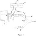
- FIG. 2An embodiment of the present invention is illustrated diagrammatically in Figure 2 .
- the temperature of the patientis maintained (or at least temperature loss is minimised) in order to reduce the chances of hypothermia, by heating inspired gas.
- inspired gasis heated in an anaesthetic delivery apparatus, during anaesthesia.
- Figure 2schematically shows part of an anaesthetic circuit.
- the circuitis a re-breathing circuit and is similar to the prior art circuit illustrated in Figure 1 , but also including a conduit 20 as inspired limb of the anaesthetic apparatus 1 and comprising a heating arrangement 21.
- the heating arrangement 21is a heating conductor running within the conduit 20.
- the conduit 20, in this embodiment,is a heated flexible hose.
- gas from the anaesthetic circuitenters a passageway 22 of the heated tube 20, which acts as the inspired limb of the re-breathing circuit, and is heated as it passes along the passageways 22.
- the heated gasenters a 'Y' piece 24 and is transmitted to the patient (who may be intubated or via a mask or some other delivery arrangement).
- Exhaled gasestravel via the expired limb 25 back into the anaesthetic circuit.
- the expired limb 25is not heated. Heating the gas in the inspired limb is sufficient to maintain the temperature of the patient. In other embodiments, however, the expired limb 25 may also include a heating arrangement to heat the expired gases to maintain temperature within the circuit, if required.
- This embodimentis a closed circuit re-breathing system.
- An alternative embodimentmay comprise a non-re-breathing open circuit, the inspired limb still being heated.
- a DC power supply 26is provided for the heating element 22 and a thermostatic controller 27 is provided to control operation of the power supply.
- a temperatures sensor 28, placed at the 'Y' piece 24 at the patient end of the heated tube 20provides feedback to the thermostatic controller 27.
- a connector 29connects to the heating element 22 to provide power.
- the temperature sensor 28extends in the 'Y' piece with its sensitive area in the inhalation gas flow.
- This sensormay typically be a thermistor, thermocouple, RTD or other suitable sensor to provide an different signal to the thermostatic controller 27.
- the thermostatic controller 27is provided with power by a mains DC power supply 26 or battery.
- the thermostatic controller 27typically functions as an "ON-OFF" device switching about set point temperature with hysteresis or in a proportional mode (e.g. PRD).
- the thermostatic controller 27may also provide a visual indication of the temperature (display).
- This embodimentuses a microprocessor thermostat which discloses a "heat off” status as well as detecting if the temperature sensor is damaged or unplugged. This shuts down the tube heating protecting the patient from overheating.
- the devicealso has a data link (not shown) to a computer giving provision for reporting the current inhaled gas temperature and reporting heating state "ON-OFF", for example every 10 seconds (or other desired period). This data can be recorded by the computer.
- FIG 12illustrates a controller in accordance with an embodiment of the present invention for controlling the tube heating.
- the controller 100comprises a display 101 for displaying current temperature of the breathing circuit or the animal.
- An auxiliary temperature probe port 102is provided to receive input from a temperature probe monitoring the actual bodily temperature of the patient.
- the temperature probecould be a rectal or oesophageal thermometer monitoring the actual bodily temperature of the patient.
- Indicators "temp probe” 103 and "temp circuit” 104indicate which temperature is being displayed by display 101 at any particular time.
- the display 101may alternate displays between the probe temperature and the temperature of the anaesthetic circuit.
- the temperature of the circuitis monitored by a temperature sensor within one of the conduits (usually the expired limb) of the anaesthetic circuit, as discussed above.
- Indicator light 105indicates that heating is on.
- the controller 100is arranged to control the heating depending on settings and also depending on feedback from the temperature probe and the temperature sensor in the circuit.
- Monitoring the animal's actual temperaturecan facilitate regulation of the heating to be applied to the conduit. Measurement of the animal's actual temperature and the temperature of the expired limb of the anaesthetic circuit can be used to monitor the heat transfer of the patient.
- the temperature sensor sensing the temperature near the breathing orifice of the patientis relatively fast in response time so that it varies as the animal breathes. This can be used in embodiments to determine the respiratory rate of the patient.
- the controller 100has a connector such as a USB port to enable data on temperature (and any other data available) to be downloaded to a computing device.
- an inspired air/limb temperature sensormay also be included, so that the differential between the inspired, the expired temperature and, if required also the actual temperature of the animal, may be monitored. This can be important for research as well as other applications.
- the temperature to which the gas is heated and the volume of the gas being provided to the patientwill depend upon the patient.
- the heating arrangementallows heating of inspired gas to be between 35-45°C. Warming inspired air is the sole source of heating for, for example, small dogs and cats, reduces heat loss and results in body temperatures of between 35-36°C. Heating to 40°C will stop animals' temperatures dropping so no additional heating may be required in the circuit.
- the tubingis reduced in diameter (to between 10-18mm, preferably between 12-16mm). In one embodiment the tubing used is 12mm diameter (bore) and in another embodiment 16mm (e.g. for larger patients).
- CPAPventilation therapy
- CPAPventilation therapy
- the heating in CPAP and the like systemsis to heat the tube so that water does not condense on the walls.
- the heating arrangementis arranged to heat the gas passing within the tube passageways.
- FIGS 3 and 4show cross-sections and exploded views of heated tubing in accordance with embodiments of the present invention.
- the heated tubing 20includes a plurality of external ribs 21 and a heating arrangement in the form of a coiled heating element 22.
- an integrated cuff 23that is used to connect to other elements 24 of the anaesthetic circuit.
- the integrated cuff 23may be coloured so that the user can tell which tubing is the heated tubing and which end they should connect to the 'Y' piece 24.
- Figure 4shows the arrangement in more detail, the heating element 22 is elliptical in cross-section and allows the heater arrangement to be torqued against the inside wall surface of the hose 22. This allows improved heat dispersion into the wall of the hose through greater contact air (note the wall of the hose contacts the gas flowing through the hose and therefore heats the gas). It also has improved aerodynamics with profiled shape and location against the tube wall.
- FIG. 5shows an exploded view of the heating element, which comprises an insulation layer 30 passing around the element.
- the heater wireis PTC TD400 wire. It includes a signal wire 31, along which data (e.g. temperature data) may be passed. It also includes a safety separation layer 32 and the heater wire 33. There is a textile core 34.
- heating wiremay be used in other embodiments and the invention is not limited to the PTC TD400 element.
- Figure 6shows a complete hose 22 with end pieces 23 and 24 attached to a controller 27 which may be plugged into a power supply.
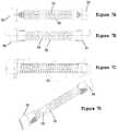
- FIGS 7A through 7Dshow various views of heated tubing which may be used in embodiments of the present invention.
- End pieces 50 of the tubing 51may be adapted to connect to standard fittings in anaesthetic circuits (e.g. 22mm), whereas the tubing bore 52 may be of different diameter (e.g. 16mm, 12mm or other diameter).
- FIGs 8A, 8B and 8Care representations of example tubing. It will be seen that the tubing is transparent, and that the heating wire passes underneath the ribs (see in particular Figure 8C , showing the heating wire 55 passing under the ribs 51).
- thisshows a novel hard plastic moulded connector 60 attached to tubing in accordance with an embodiment of the invention 61.
- the connectoris arranged to connect to a standard 22mm anaesthesia machine.
- Figure 8Eshows a soft rubber connector 63 and Figure 8F shows an old-style respiratory connector 64.
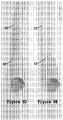
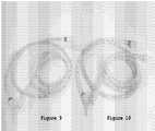
- Figure 9shows an example of 12mm tubing (the red tagged connectors are for the heated tubing and the non-coloured connectors are to the expired limb of the tubing).
- Figure 10shows an example of 16mm tubing.
- Figure 11shows an electrical connector 70 being connected to heated tubing examples 71.
- the smooth walled tubing as discussed abovepromotes laminar flow (not turbulent) so is low resistance. This means that lower diameters can be used than with conventional anaesthetic circuits.
- animals' temperature at the end of 1-3 hour anaesthesia for ophthalmology surgery using heated tubingis around 35.5-38°C with airway heating alone. Otherwise it would be between 32-35°C or they would need a warm air heating blanket.
- the absorbance of carbon dioxide sodalimeis exothermic with and gives off water. This can be used to keep the gas humidified.
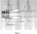
- This graphshows results of resistance to airflow, adjusted for connection restrictions and standardized for length (per meter). Airflows were tested from 10-50L/min (which covers an animal range of -7.5-10kg (vertical line 'A') up to -55-80kg (vertical line 'B').
- 12mm hose embodimenthas less resistance than traditional corrugated 15mm ID hose (known as "paediatric” breathing hose) and similar resistance to the expiratory limb (inside hose) of a Universal "F" circuit at flows less than 25L/min (equivalent to a 20-30kg dog's breath).
- 16mm hose embodimenthas similar resistance to Plastiflex 20mm ID smooth wall hose and similar resistance to standard corrugated 22mm ID hose at flows up to 50L/min (equivalent to a breath from a 55-80kg dog).
- Test results for individual hosesare shown in the tables below.
- the purple highlighted columnshows the data adjusted for hose connections and length.
- heatingis applied to the conduit by the heating apparatus in the form of a heating element.
- heatingmay be applied to the conduit in other ways.
- heatingmay be applied externally, for example by passing the conduit through a warming device e.g. a water bath, or an electrical bath.
- the conduitmay be heated by a blanket which is in turn being used to maintain the warmth of the patient.
- Heating blankets for use during recovery and surgeryare known. They may use warm air passing through the blanket to maintain the heat of the patient.
- Such heating blanketsare disclosed in the Applicant's earlier patent applications PCT/AU2003/001626 , PCT/AU2007/001553 , PCT/AU2010/000383 and PCT/AU2011/000410 .
- the conduitmay be placed contiguous with a surface of the heating blanket, in order to heat the conduit and therefore the air within the conduit.
- the tubingwould not necessarily need a heating element in order to provide the same advantages of heating the air, as discussed above.
- an anaesthetic apparatus for keeping a patient warmis disclosed.
- a warmed hosecould be used on an inspiration tubing to warm air (or other gas) being breathed by a patient in recovery.
- the apparatusutilises heated tubing which may be circular in diameter.
- heated tubingwhich may be circular in diameter.
- the inventionis not limited to circular tubing.
- the cross-section of the tubingmay be other shapes such as elliptical.
Landscapes
- Health & Medical Sciences (AREA)
- Anesthesiology (AREA)
- Veterinary Medicine (AREA)
- Life Sciences & Earth Sciences (AREA)
- Engineering & Computer Science (AREA)
- Public Health (AREA)
- General Health & Medical Sciences (AREA)
- Animal Behavior & Ethology (AREA)
- Heart & Thoracic Surgery (AREA)
- Hematology (AREA)
- Pulmonology (AREA)
- Biomedical Technology (AREA)
- Emergency Medicine (AREA)
- Wood Science & Technology (AREA)
- Zoology (AREA)
- Pharmaceuticals Containing Other Organic And Inorganic Compounds (AREA)
- Thermotherapy And Cooling Therapy Devices (AREA)
Description
- The present invention relates to an apparatus for maintaining patient temperature during a medical procedure and, particularly, but not exclusively, to an apparatus for maintaining patient temperature during anaesthesia.
- A problem with medical procedures such as, for example, surgery is maintenance of the temperature of the patient.
- This is a particular problem for smaller patients, for example, less than 40kgs. It has been found that for in the order of 85% of small animals (less than 40kgs, but more particular less than 30kgs and more particular less than 20kgs), the body temperature drops below their normal body temperature during an anaesthetic procedure. There is therefore a significant danger of hypothermia, and consequent complications associated with this, including slow recovery time.
EP 1 352 670 A1US 4 967 744 A andWO 2009/250055 A1 disclose a coaxial breathing system with an inlet tube for conveying inspiratory gases and an outlet tube for conveying expiratory gases, where the inlet tube is coaxially arranged within the outlet tube. A heating wire is wrapped around the inlet tube.US 2009/250055 A1 discloses a device for respirating patients and a process for regulating the humidity of breathing air in such a device.US 2009/197982 A1 discloses a heated breathing circuit detection system which verifies the proper setup and connection of a breathing circuit to a heater unit of a humidification system, in which gases and vapours in inspiratory and expiratory limbs are heated by separate heater elements to ensure that humidified gas is delivered to the patient without the risk of condensation. Two temperature sensors are placed at opposite ends of the inspiratory limb to measure the temperature of the humified gas at these opposite ends of the inspiratory limbs. These temperatures are forwarded to a controller controlling the heater elements to ensure that the temperature withininspiratory limb 22 is maintained at a level to prevent rainout (condensation on the walls) occurring in the inspiratory limb.- In accordance with a first aspect, the present invention provides an anaesthetic apparatus arranged for the delivery of anaesthesia to a patient, the apparatus comprising a conduit for delivering a gas including anaesthetic to a patient, the conduit comprising a heating arrangement arranged to heat the gas within the conduit, the apparatus further comprising a first temperature sensor arranged to sense temperature at a breathing orifice of a patient when a patient is connected to the apparatus and a second temperature sensor arranged to sense the actual bodily temperature of the patient, and a controller arranged to receive from the first temperature sensor the sensed temperature at the breathing orifice of the patient and receive from the second temperature sensor the sensed temperature of the patient, the controller being configured to regulate the output of the heating arrangement to control heating depending on feedback from the second temperature sensor and the first temperature sensor, said heating arrangement is arranged to heat the gas between 35°C and 45°C.
- Advantageously, heating the gas facilitates maintenance of the temperature of the patient, as the patient breaths the heated gas.
- The present Applicant's have found that, in conventional anaesthesia, where the gas is not heated, the process of breathing the anaesthetic gas (which is usually cool and dry) contributes to cooling of the patient leading to potential hypothermia. Embodiments of the present invention minimise this danger by heating the gas within the anaesthetic apparatus so that the patient is breathing heated gas.
- The temperature to which the gas is heated will depend upon the type of patient. Animals under 40kgs, small animals (30kgs or less), depending on the usual body temperature and size of animal, the gas will be heated to between 35-45°C.
- In an embodiment, the apparatus comprises an anaesthetic circuit, comprising at least an inspired limb (the part of the circuit through which gas is provided to the patient). In this embodiment, the inspired limb comprises the conduit. Gas on the way to the patient is therefore heated. The anaesthetic apparatus may also comprise an expired limb. This may or may not comprise a heated conduit.
- In an embodiment, the anaesthetic apparatus comprises a re-breathing circuit (circle system). In an alternative embodiment, the anaesthetic apparatus may comprise a non-re-breathing circuit (open system).
- In an embodiment, the conduit comprises tubing, comprising a tubing wall defining a passageway along which gas may pass. In an embodiment the internal surface of the tubing wall (adjacent the passageway) is smooth. This contrasts with typical tubing used in prior art anaesthetic circuits, which is corrugated. In an embodiment, the heating arrangement comprises a conductive element wound about the tubing wall. In an embodiment, the heating element is wound about the internal surface tubing adjacent the passageway. In an alternative embodiment, the element is wound within the tubing wall. In an embodiment, the tubing has ribs around the wall. In an embodiment, the heating element is wound around underneath or inside the ribs. In an embodiment, the heating element is a conductive wire. Electricity is passed through the wire to heat it.
- The Applicant's have found that having smooth wall tubing facilities heating of the gas within the bore of the tubing. They have also found that the smooth wall facilitates flow of the gas along the passageway.
- In an embodiment, the passageway of the tubing is between 10-18mm in diameter. In an embodiment, it is between 12-16mm. In one embodiment, the tubing has a bore of 12mm. In another embodiment, the tubing has a bore of 16mm.
- Conventional tubing used in an anaesthetic apparatus is in the order of 20-25mm (usually 20-22mm) in diameter. It has been previously thought that lower passageway diameters may lead to high resistance within the anaesthetic circuit leading to difficulty in the patient breathing. The Applicant's have found, surprisingly, that with smooth walled tubing, lesser diameters than 20mm can be used without deleteriously increasing the resistance of the anaesthetic circuit and affecting patients breathing. Further, with lower diameter tubing, the Applicant's have found that the gas flowing within the passageway is heated more effectively.
- In an embodiment, the anaesthetic apparatus comprises temperature controller, arranged to regulate the heating arrangement to maintain temperature of the gas at a predetermined level. In an embodiment, the apparatus further comprises a temperature monitor arranged to monitor the temperature of the gas. In an embodiment, the temperature sensor is positioned proximate the breathing orifice of the patient, in use, in order to measure the expired temperature. Where the apparatus comprises an anaesthetic circuit, the temperature sensor may be positioned in the expired limb of the circuit.
- In an embodiment, the temperature controller may be arranged to receive an input indicative of the patient's actual temperature. A temperature sensor in the patient (e.g. rectal or oesophageal thermometer, or any other type of temperature sensor) may provide information on the patient's actual body temperature to the temperature controller. This can be used by the temperature controller to regulate the output of the heating arrangement. For example, if the patient is too warm, no heating may be provided by the heating arrangement. If the patient is too cold, heating may be increased.
- In an embodiment, where there is a temperature monitor monitoring expired breath temperature or the temperature of the anaesthetic circuit, and a temperature monitor monitoring temperature of the animal, the differential temperature (between the animal and the circuit) can be monitored. This may allow a measurement of heat gained or lost as controlled by the anaesthetic apparatus. This can be particularly useful for research, for example, as well as having other uses.
- It is known to maintain the warmth of patients during surgery and anaesthesia by using patient warming blankets placed around, under or over the patient. See Applicant's earlier patent application numbers
PCT/AU2003/001626 PCT/AU2007/001553 PCT/AU2010/000383 PCT/AU2011/000410 - Features and advantages of the present invention will become apparent from the following description of embodiments thereof, by way of example only, with reference to the accompanying drawings, in which:
Figure 1 is a diagram of a prior art anaesthetic circuit;Figure 2 is a diagram of part of an anaesthetic apparatus in accordance with an embodiment of the present invention;Figure 3 is a sectional view of a conduit and heating arrangement in accordance with an embodiment of the present invention;Figure 4 is an exploded view of a conduit and heating arrangement in accordance with an embodiment of the present invention;Figure 5 is a diagram of a heating element for a heating arrangement in accordance with an embodiment of the present invention;Figure 6 shows a conduit and heating arrangement in accordance with an embodiment of the present invention;Figures 7A to 7D are various views of heated tubing used with an apparatus in accordance with an embodiment of the present invention;Figures 8D to 8E are perspective views of embodiments of heated tubing in accordance with the present invention;Figures 8A to 8F are further embodiments of heated tubing in accordance with the present invention showing end connectors;Figures 9 and 10 are views of anaesthetic lines for an anaesthetic apparatus in accordance with embodiments of the present invention including heated tubing in accordance with embodiments of the present invention;Figure 11 is a view of heated tubing in accordance with an embodiment of the present invention, showing a connector for connecting a power supply to a heating element; andFigure 12 is a front view of a control panel for an apparatus such as shown and described with reference toFigures 2-11 .- Referring to
Figure 1 , a prior art anaesthetic circuit of the re-breathing type (circle type) is illustrated. The anaesthetic circuit is designated generally byreference numeral 1. Theanaesthetic circuit 1 includes a means of providing oxygen, in this case being agas cylinder 2 containing oxygen. Aregulator 3 is provided to regulate the pressure of the oxygen supply and a flow meter 4 provides an indication of the gas flow. Avaporiser 5 is provided for introduction of anaesthetic (and perhaps additional gases) to the gas flow. The system includesanaesthesia lines anaesthetic lines distal opening 8 of a mask 9. The mask 9 is used to provide gas to the patient's mouth and/or nose. Other means for delivering gas to the patient's respiratory orifice, apart from a mask may be used, for example, the patient may be intubuted. Any other means be used. - Fresh gas flow comes down
line 6 from thevaporiser 5 in the direction ofarrow 10.Line 5 is the"inspired limb". - Exhaust gas flow travels up the
other line 26"expired limb",arrow 11. Areservoir bag 12 is connected to the distal end of theexpired limb 6 and has an outlet which proceeds to ascrubber 30 which is arranged to remove carbon dioxide from the exhaust gas. The scrubbed gas re-enters the lines at the other side of thescrubber 30. - This is one type of circuit in which the patient re-breaths scrubbed air. It is the most popular circuit that is used for human anaesthesia, and is also used in veterinary anaesthesia. It is effective in reducing pollution and waste gases.
- Other types of circuit include in the non-re-breathing circuit, where exhaled gases are not re-breathed, but instead scavenged. The supply of gas/ anaesthetic is a continuous supply. Non-re-breathing circuits are generally used with smaller patients, such as small animals (less than 25kgs), neonates and small infants.
- A problem with traditional anaesthetic systems, whether a closed circuit re-breathing systems, or open circuit non-re-breathing systems, is that the patient tends to lose heat with every breath, because they are breathing cold, dry gas. For small animal patients (e.g. less than 30kgs, even more so when less than 25kgs even more so less than 20kgs), hypothermia may occur in up to 85% of anaesthetised patients. The small animal patient's temperatures can commonly fall to between 30-34°C, which can result in dangerous hypothermia and poorer quality recoveries. Warming animals in recovery is slow, consumes a lot of nursing time and, if managed incorrectly, can result in thermal injuries e.g. being burnt by warming devices, such as hot water bottles or electrical heating pads. The Applicant's believe the prevention of heat loss in the first place is a more effective problem management strategy.
- Heat loss or gain occurs in an exponential manner with its greatest impact on small patients. In part this is because of their large body surface area relative to body mass. Hypothermia occurs in anaesthetised cats, dogs and even young foals, during anaesthesia.
- Further, anaesthesia depresses CNS thermo regulation and prevents the usual methods of conserving heat such as seeking warm environments, body positioning, hair coat direction and peripheral vasoconstriction all generating heat by shivering. Heat loss during surgery is exacerbated by clipping hair from surgery sites, using cold or evaporated skin prep solutions, wetting and flatting the hair coat, opening body cavities.
- Problems with hypothermia include:
- ▪ CNS depression which reduces the requirement for anaesthetic drugs so patients appear "deeper"
- ▪ lower tissue blood flow alters drug distribution, metabolism and excretion, prolonging recovery
- ▪ peripheral vasoconstriction decreases surface heating efficiency
- Preventing hypothermia during surgery traditionally relies on skin surface contact heating from hot water filled bottles, circulating warm water blankets and electric heating pads placed under the animal or under the surgery table top. IV fluid has been warmed by placing IV fluid lines in dishes of warm water.
- A calorie (cal) is the amount of heat required to raise 1ml (or 1gm) of H2O 1 °C. The specific heat of animal tissue is 0.83cal/gm. Therefore a 10kg dog requires 8,300cal (8.3kcal) to raise its
temperature 1°C. - A 10kg dog administered IV fluid at 10ml/kg/hr = 100ml/hr. If the fluid is warmed to 44°C and the dog is 34°C, then we can deliver:

- To warm the 10kg at 34°C dog to 37°C, the dog needs:

- Warming IV fluid may prevent cold fluid exacerbating heat loss but is not effective for warming severely hypothermic animals.
- During inspiration the nose and pharyngeal mucosa transfer heat and moisture to the air which is largely recovered during expiration, thus conserving heat. Air has a low heat capacity (0.24cal/gm) and a low weight (1.3gm/l). Saturated air holds 44mg H2O/L at 37°C which requires 24 calories. A 10kg dog taking 20 x 100ml breaths/min ventilates 120L/hr so requires (24cal/L x 120 L/hr) = 2880 cal/hr for humidification. Intubation inhibits heat/moisture conservation via the nose, resulting in body temperature loss of about 1/3°C/hr.
- Thermal injury to skin is an exponential relationship between source temperature and contact time. Burns do occur at temperatures below 50°C and are still commonly seen. Hot tap water may reach 60°C and 10 seconds of skin contact would result in epidermal necrosis. In 2008 the UK Veterinary Defence Society reported a high incidence of burns caused by use of warmed wheat bags which can produce similar temperatures.
- Electric heating pads usually have a low thermal mass and cycle on until the thermostat reaches its high point, then cycle off until cooling to the low point, then turn back on repeating the process. Simple controllers can be variable in performance or fail, causing higher temperature delivery and potentially burns. These devices should always be insulated from the animal's skin surface.
- An embodiment of the present invention is illustrated diagrammatically in
Figure 2 . In this embodiment, the temperature of the patient is maintained (or at least temperature loss is minimised) in order to reduce the chances of hypothermia, by heating inspired gas. In this embodiment, inspired gas is heated in an anaesthetic delivery apparatus, during anaesthesia. Figure 2 schematically shows part of an anaesthetic circuit. In this embodiment, the circuit is a re-breathing circuit and is similar to the prior art circuit illustrated inFigure 1 , but also including aconduit 20 as inspired limb of theanaesthetic apparatus 1 and comprising a heating arrangement 21. In this embodiment, the heating arrangement 21 is a heating conductor running within theconduit 20. Theconduit 20, in this embodiment, is a heated flexible hose.- In more detail, gas from the anaesthetic circuit (e.g. vaporiser and ventilator arrangement 22) enters a
passageway 22 of theheated tube 20, which acts as the inspired limb of the re-breathing circuit, and is heated as it passes along thepassageways 22. The heated gas enters a 'Y'piece 24 and is transmitted to the patient (who may be intubated or via a mask or some other delivery arrangement). - Exhaled gases travel via the expired
limb 25 back into the anaesthetic circuit. - In this embodiment the expired
limb 25 is not heated. Heating the gas in the inspired limb is sufficient to maintain the temperature of the patient. In other embodiments, however, the expiredlimb 25 may also include a heating arrangement to heat the expired gases to maintain temperature within the circuit, if required. - This embodiment is a closed circuit re-breathing system. An alternative embodiment may comprise a non-re-breathing open circuit, the inspired limb still being heated.
- A
DC power supply 26 is provided for theheating element 22 and athermostatic controller 27 is provided to control operation of the power supply. Atemperatures sensor 28, placed at the 'Y'piece 24 at the patient end of theheated tube 20 provides feedback to thethermostatic controller 27. Aconnector 29 connects to theheating element 22 to provide power. - The
temperature sensor 28 extends in the 'Y' piece with its sensitive area in the inhalation gas flow. This sensor may typically be a thermistor, thermocouple, RTD or other suitable sensor to provide an different signal to thethermostatic controller 27. - The
thermostatic controller 27 is provided with power by a mainsDC power supply 26 or battery. Thethermostatic controller 27 typically functions as an"ON-OFF" device switching about set point temperature with hysteresis or in a proportional mode (e.g. PRD). Thethermostatic controller 27 may also provide a visual indication of the temperature (display). - This embodiment uses a microprocessor thermostat which discloses a"heat off" status as well as detecting if the temperature sensor is damaged or unplugged. This shuts down the tube heating protecting the patient from overheating. The device also has a data link (not shown) to a computer giving provision for reporting the current inhaled gas temperature and reporting heating state"ON-OFF", for example every 10 seconds (or other desired period). This data can be recorded by the computer.
Figure 12 illustrates a controller in accordance with an embodiment of the present invention for controlling the tube heating. Thecontroller 100 comprises adisplay 101 for displaying current temperature of the breathing circuit or the animal. An auxiliarytemperature probe port 102 is provided to receive input from a temperature probe monitoring the actual bodily temperature of the patient. For example, the temperature probe could be a rectal or oesophageal thermometer monitoring the actual bodily temperature of the patient. Indicators "temp probe" 103 and "temp circuit" 104 indicate which temperature is being displayed bydisplay 101 at any particular time. Thedisplay 101 may alternate displays between the probe temperature and the temperature of the anaesthetic circuit. The temperature of the circuit is monitored by a temperature sensor within one of the conduits (usually the expired limb) of the anaesthetic circuit, as discussed above.Indicator light 105 indicates that heating is on. Thecontroller 100 is arranged to control the heating depending on settings and also depending on feedback from the temperature probe and the temperature sensor in the circuit.- Monitoring the animal's actual temperature can facilitate regulation of the heating to be applied to the conduit. Measurement of the animal's actual temperature and the temperature of the expired limb of the anaesthetic circuit can be used to monitor the heat transfer of the patient.
- In an embodiment the temperature sensor sensing the temperature near the breathing orifice of the patient (e.g. in the expired limb of an anaesthetic circuit) is relatively fast in response time so that it varies as the animal breathes. This can be used in embodiments to determine the respiratory rate of the patient.
- The
controller 100 has a connector such as a USB port to enable data on temperature (and any other data available) to be downloaded to a computing device. - In an embodiment, where the apparatus is implemented in an anaesthetic circuit, an inspired air/limb temperature sensor may also be included, so that the differential between the inspired, the expired temperature and, if required also the actual temperature of the animal, may be monitored. This can be important for research as well as other applications.
- The temperature to which the gas is heated and the volume of the gas being provided to the patient will depend upon the patient. In this embodiment, the heating arrangement allows heating of inspired gas to be between 35-45°C. Warming inspired air is the sole source of heating for, for example, small dogs and cats, reduces heat loss and results in body temperatures of between 35-36°C. Heating to 40°C will stop animals' temperatures dropping so no additional heating may be required in the circuit.
- One of the problems with heating gas passing within a passageway within a tube is that the gas may not be heated sufficiently. Typical human anaesthetic circuits use 20mm or 22mm tubing. We have found that using this width of tubing may mean that the gas may not heat sufficiently. Further, typical tubing is corrugated. This can lead to turbulent flows, higher resistance and further difficulties in delivering heated gas. In the present embodiment, the tubing is reduced in diameter (to between 10-18mm, preferably between 12-16mm). In one embodiment the tubing used is 12mm diameter (bore) and in another embodiment 16mm (e.g. for larger patients).
- Using lower diameter tubing is counter-intuitive, as it would be considered that this would provide a resistance to breathing that may be difficult for the patient under anaesthetic to overcome (particularly small animals). By providing smooth walled tubing which allows a laminar flow of gas along the tubing, this problem has been avoided. Low bore tubings, which allow for sufficient heating of the gas but still do not have great resistance to flow of gas to a patient, are therefore utilised in this embodiment.
- Note that it is known in ventilation therapy, such as CPAP, to heat tubing in anexpired limb in order to prevent"rainout" (condensation within the tubing). Heating in these systems is to 32°C (which would be insufficient to prevent hypothermia and would be ineffective anyway because it would be in the expired pathway). Further, the heating in CPAP and the like systems is to heat the tube so that water does not condense on the walls. In the present invention, the heating arrangement is arranged to heat the gas passing within the tube passageways.
Figures 3 and4 show cross-sections and exploded views of heated tubing in accordance with embodiments of the present invention. Referring toFigure 3 , theheated tubing 20 includes a plurality of external ribs 21 and a heating arrangement in the form of acoiled heating element 22. Also note there is anintegrated cuff 23 that is used to connect toother elements 24 of the anaesthetic circuit. Theintegrated cuff 23 may be coloured so that the user can tell which tubing is the heated tubing and which end they should connect to the 'Y'piece 24.Figure 4 shows the arrangement in more detail, theheating element 22 is elliptical in cross-section and allows the heater arrangement to be torqued against the inside wall surface of thehose 22. This allows improved heat dispersion into the wall of the hose through greater contact air (note the wall of the hose contacts the gas flowing through the hose and therefore heats the gas). It also has improved aerodynamics with profiled shape and location against the tube wall.Figure 5 shows an exploded view of the heating element, which comprises aninsulation layer 30 passing around the element. In this embodiment, the heater wire is PTC TD400 wire. It includes asignal wire 31, along which data (e.g. temperature data) may be passed. It also includes asafety separation layer 32 and theheater wire 33. There is atextile core 34.- Note that other heating wire may be used in other embodiments and the invention is not limited to the PTC TD400 element.
Figure 6 shows acomplete hose 22 withend pieces controller 27 which may be plugged into a power supply.Figures 7A through 7D , show various views of heated tubing which may be used in embodiments of the present invention.End pieces 50 of thetubing 51 may be adapted to connect to standard fittings in anaesthetic circuits (e.g. 22mm), whereas the tubing bore 52 may be of different diameter (e.g. 16mm, 12mm or other diameter).Figures 8A, 8B and8C are representations of example tubing. It will be seen that the tubing is transparent, and that the heating wire passes underneath the ribs (see in particularFigure 8C , showing theheating wire 55 passing under the ribs 51).- Referring to
Figure 8D , this shows a novel hard plastic mouldedconnector 60 attached to tubing in accordance with an embodiment of theinvention 61. The connector is arranged to connect to a standard 22mm anaesthesia machine. Figure 8E shows asoft rubber connector 63 andFigure 8F shows an old-style respiratory connector 64.Figure 9 shows an example of 12mm tubing (the red tagged connectors are for the heated tubing and the non-coloured connectors are to the expired limb of the tubing). Similarly,Figure 10 shows an example of 16mm tubing.Figure 11 shows anelectrical connector 70 being connected to heated tubing examples 71.- The smooth walled tubing as discussed above, promotes laminar flow (not turbulent) so is low resistance. This means that lower diameters can be used than with conventional anaesthetic circuits.
- In an example embodiment, animals' temperature at the end of 1-3 hour anaesthesia for ophthalmology surgery using heated tubing (typically heats to 38-42°C with 24 volt DC power supply) is around 35.5-38°C with airway heating alone. Otherwise it would be between 32-35°C or they would need a warm air heating blanket.
- 12mm ID tube x 1.5m long - volume 170ml:
- Non-heated weight 58gm
- Heated weight 68gm
15mm ID tube x 1.5m long - volume 300ml:- Non-heated weight 72gm
- Heated weight 74gm
In embodiments, a humidifier can be added to the anaesthetic system to humidify the gas.
- In re-breathing circuits, the absorbance of carbon dioxide sodalime is exothermic with and gives off water. This can be used to keep the gas humidified.
- The following examples give test results for resistance of various different types of hoses, including the 12mm and 16mm hoses in accordance with embodiments of the present invention.
- All hoses were tested as they were produced, connected to standard anaesthetic machine 22mm Tapered outlets identical to ones found on all soda lime absorbers near the one-way valves.
- 10-50L/min air was delivered from a calibrated flowmeter and passed through the hose while it was flat and straight ensuring no pressure variances due to gravity or a coiled hose. Shown below in the table is the Comparative Breathing Hose Resistance which has not been adjusted for length or for the restriction size from 22mm. Included in the results in the last column are resistance values of a standard 22 13mm ID restriction described in the method.

- For the tested hoses, approximations were made for the restriction resistance and will be taken from the above table. The highlighted section shows the pressure drop for a standard 22-13mm Orifice like those found in smaller hoses. After the restrictions were accounted for, approximations were made for resistance in the breathing hoses per meter. Each individual hose's test data and adjusted data are shown in the following tables. The hose at the top of each Table and final resistance/metre value is highlighted.
- This adjusted (indexed) data enabled us to make an approximate comparison on the efficiency of each hose design. Based on clinical experience and work from other researchers, we consider resistance of less than 0.5cm H2O to be of negligible importance.

- This graph shows results of resistance to airflow, adjusted for connection restrictions and standardized for length (per meter). Airflows were tested from 10-50L/min (which covers an animal range of -7.5-10kg (vertical line 'A') up to -55-80kg (vertical line 'B').
- 12mm hose embodiment has less resistance than traditional corrugated 15mm ID hose (known as"paediatric" breathing hose) and similar resistance to the expiratory limb (inside hose) of a Universal "F" circuit at flows less than 25L/min (equivalent to a 20-30kg dog's breath).
- 16mm hose embodiment has similar resistance to Plastiflex 20mm ID smooth wall hose and similar resistance to standard corrugated 22mm ID hose at flows up to 50L/min (equivalent to a breath from a 55-80kg dog).
- Test results for individual hoses are shown in the tables below. The purple highlighted column shows the data adjusted for hose connections and length.


- In the above embodiments, heating is applied to the conduit by the heating apparatus in the form of a heating element. In an alternative embodiment, heating may be applied to the conduit in other ways. For example, heating may be applied externally, for example by passing the conduit through a warming device e.g. a water bath, or an electrical bath. In another example, the conduit may be heated by a blanket which is in turn being used to maintain the warmth of the patient. Heating blankets for use during recovery and surgery are known. They may use warm air passing through the blanket to maintain the heat of the patient. Such heating blankets are disclosed in the Applicant's earlier patent applications
PCT/AU2003/001626 PCT/AU2007/001553 PCT/AU2010/000383 PCT/AU2011/000410 - In the above embodiment an anaesthetic apparatus for keeping a patient warm is disclosed. In alternative examples, a warmed hose could be used on an inspiration tubing to warm air (or other gas) being breathed by a patient in recovery.
- In the above embodiments, the apparatus utilises heated tubing which may be circular in diameter. The invention is not limited to circular tubing. The cross-section of the tubing may be other shapes such as elliptical.
- While the above described embodiments of the invention are particularly suitable for maintaining heat of small patients during medical procedures, the invention is not limited to this. The invention may be used with larger patients including human adults.


Claims (10)
- An anaesthetic apparatus (1) arranged for the delivery of anaesthesia to a patient, the apparatus (1) comprising a conduit (20) for delivering a gas including anaesthetic to a patient, the conduit (20) comprising a heating arrangement (21) arranged to heat the gas within the conduit (20), the apparatus (1) further comprising a first temperature sensor (28) arranged to sense temperature at a breathing orifice of a patient when a patient is connected to the apparatus (1),characterised by a second temperature sensor arranged to sense the actual bodily temperature of the patient, and a controller (27, 100) arranged to receive from the first temperature sensor (28) the sensed temperature at the breathing orifice of the patient and receive from the second temperature sensor the sensed temperature of the patient, the controller (27, 100) being configured to regulate the output of the heating arrangement (21) to control heating depending on feedback from the second temperature sensor and the first temperature sensor (28), said heating arrangement (21) is arranged to heat the gas to a temperature in a range between 35-45°C.
- An anaesthetic apparatus (1) in accordance with Claim 1, comprising an inspired limb of the anaesthetic apparatus (1), the inspired limb comprising the conduit (20).
- An anaesthetic apparatus (1) in accordance with Claim 1 or 2, wherein the conduit (20) comprises tubing, comprising a tubing wall defining a passageway along which gas may pass, the internal surface of the tubing wall being smooth.
- An anaesthetic apparatus (1) in accordance with Claim 3, wherein the heating arrangement (21) comprises a conductive heating element (22) wound about the tubing wall.
- An anaesthetic apparatus (1) in accordance with Claim 4, wherein the conductive heating element (22) is wound about the internal surface of the tubing wall.
- An anaesthetic apparatus (1) in accordance with any one of Claims 3 to 5, wherein the passageway of the tubing is between 10-18mm in diameter, more particularly between 12-16mm, more particularly 12mm or 16mm.
- An anaesthetic apparatus (1) in accordance with any one of the preceding claims, wherein the controller (27, 100) is arranged to monitor heat transfer to a patient based on actual temperature of a patient and temperature of gas expired by the patient sensed by the first temperature sensor (28) at the breathing orifice and the controller (27, 100) is arranged to further regulate the heating arrangement (21) for heating the gas based on the heat transfer.
- An anaesthetic apparatus (1) in accordance with Claim 7 wherein the first temperature sensor (28) is relatively fast in response time and the controller (27, 100) is arranged to monitor respiratory rate based on fast variation in the sensed temperature.
- An anaesthetic apparatus (1) in accordance with any one of the preceding claims wherein the heating arrangement (21) is heated tubing comprising tubing arranged to form a conduit for the flow of gases in the anaesthetic apparatus and comprising a heating arrangement (21) for heating the gases within the conduit (20), wherein the heating arrangement (21) comprises at least one coiled heating element (22).
- An anaesthetic apparatus (1) in accordance with Claim 9, wherein a diameter of the conduit (20) is between 10 to 18mm, more particularly between 12 to 16mm, more particularly 12mm or 16mm.
Applications Claiming Priority (3)
| Application Number | Priority Date | Filing Date | Title |
|---|---|---|---|
| AU2011903770AAU2011903770A0 (en) | 2011-09-14 | Apparatus and method for maintaining patient temperature during a procedure | |
| AU2012903900AAU2012903900A0 (en) | 2012-09-07 | Apparatus and method for maintaining patient temperature during a procedure | |
| PCT/AU2012/001103WO2013037004A1 (en) | 2011-09-14 | 2012-09-14 | Apparatus and method for maintaining patient temperature during a procedure |
Publications (3)
| Publication Number | Publication Date |
|---|---|
| EP2755711A1 EP2755711A1 (en) | 2014-07-23 |
| EP2755711A4 EP2755711A4 (en) | 2015-03-11 |
| EP2755711B1true EP2755711B1 (en) | 2021-04-14 |
Family
ID=47882452
Family Applications (1)
| Application Number | Title | Priority Date | Filing Date |
|---|---|---|---|
| EP12830937.4AActiveEP2755711B1 (en) | 2011-09-14 | 2012-09-14 | Apparatus for maintaining patient temperature during a procedure |
Country Status (6)
| Country | Link |
|---|---|
| US (1) | US9693848B2 (en) |
| EP (1) | EP2755711B1 (en) |
| AU (2) | AU2012308102A1 (en) |
| CA (1) | CA2848745C (en) |
| DK (1) | DK2755711T3 (en) |
| WO (1) | WO2013037004A1 (en) |
Families Citing this family (17)
| Publication number | Priority date | Publication date | Assignee | Title |
|---|---|---|---|---|
| DK3685877T3 (en)* | 2011-06-03 | 2023-10-02 | Fisher & Paykel Healthcare Ltd | MEDICAL TUBES CONSISTING OF CONDUCTIVE FILAMENTS AND METHODS OF PRODUCTION |
| EP2755711B1 (en) | 2011-09-14 | 2021-04-14 | Colin Dunlop | Apparatus for maintaining patient temperature during a procedure |
| CA3207604A1 (en) | 2012-04-05 | 2013-10-10 | Fisher & Paykel Healthcare Limited | Breathing assistance apparatus with serviceability features |
| US12390614B2 (en)* | 2013-05-17 | 2025-08-19 | Sahamed Technologies, Llc | Humidification of ventilator gases |
| US9561341B2 (en)* | 2013-05-17 | 2017-02-07 | Katarina Short | Humidification of ventilator gases |
| US9692838B2 (en) | 2014-12-09 | 2017-06-27 | Facebook, Inc. | Generating business insights using beacons on online social networks |
| US9729667B2 (en) | 2014-12-09 | 2017-08-08 | Facebook, Inc. | Generating user notifications using beacons on online social networks |
| DE102014018602A1 (en)* | 2014-12-17 | 2016-06-23 | Drägerwerk AG & Co. KGaA | Narkosemittelverdunstereinheit |
| WO2016145211A1 (en)* | 2015-03-10 | 2016-09-15 | Life Warmer Inc. | Thermic infusion system |
| US11839719B2 (en) | 2017-01-30 | 2023-12-12 | Globalmed, Inc. | Heated respiratory hose wiring |
| US11052214B2 (en) | 2017-01-30 | 2021-07-06 | Globalmed, Inc. | Heated respiratory hose wiring |
| US11813403B2 (en) | 2017-01-30 | 2023-11-14 | Globalmed, Inc. | Heated respiratory hose wiring |
| IT201800005588A1 (en)* | 2018-05-22 | 2019-11-22 | METHOD OF CONTROL OF A THERMOREGULATED VENTILATION CIRCUIT. | |
| CN111657944A (en)* | 2020-05-08 | 2020-09-15 | 中国科学院合肥物质科学研究院 | Experimental device applied to small animal MRI experiment and using method |
| US12427282B2 (en)* | 2020-09-09 | 2025-09-30 | Covidien Lp | Systems and methods for active humidification in ventilatory support |
| CN115253020B (en)* | 2022-08-11 | 2023-10-03 | 临沂市兴华医用器材有限公司 | Can prevent anesthesia pipe subassembly of damage |
| WO2024130313A1 (en)* | 2022-12-21 | 2024-06-27 | Colin Dunlop | An apparatus for delivering fluid to a small patient |
Citations (1)
| Publication number | Priority date | Publication date | Assignee | Title |
|---|---|---|---|---|
| US20090107982A1 (en)* | 2007-10-29 | 2009-04-30 | Smiths Medical Asd, Inc. | Heated breathing circuit detection |
Family Cites Families (14)
| Publication number | Priority date | Publication date | Assignee | Title |
|---|---|---|---|---|
| US4967744A (en) | 1988-11-03 | 1990-11-06 | Airoflex Medical, Inc. | Flexible breathing circuit |
| WO1997018001A1 (en)* | 1995-11-13 | 1997-05-22 | Fisher & Paykel Limited | Heated respiratory conduit |
| AU2002211121B2 (en)* | 2000-10-16 | 2005-11-03 | Fisher & Paykel Healthcare Limited | Improvements to apparatus used for the humidification of gases in medical procedures |
| GB0208358D0 (en) | 2002-04-11 | 2002-05-22 | Armstrong Medical Ltd | Breathing system |
| AU2002953185A0 (en) | 2002-12-09 | 2002-12-19 | Colin Dunlop | Patient warming system |
| WO2005028012A1 (en)* | 2003-09-19 | 2005-03-31 | Fisher & Paykel Healthcare Limtied | A connector |
| WO2008043155A1 (en) | 2006-10-13 | 2008-04-17 | Colin Dunlop | Animal warming apparatus and method |
| EP2079505B1 (en)* | 2006-11-08 | 2020-07-15 | ResMed Pty Ltd | Conduit for use in a respiratory apparatus |
| MX2010001827A (en)* | 2007-08-14 | 2010-06-01 | Plastiflex Belgium | A respiratory system. |
| DE102008001022A1 (en) | 2008-04-07 | 2009-10-08 | Dräger Medical AG & Co. KG | Device for ventilating patients |
| GB2481774B (en) | 2009-04-01 | 2013-12-11 | Colin Dunlop | Improved patient warming system |
| AU2010206053B2 (en)* | 2009-07-31 | 2014-08-07 | ResMed Pty Ltd | Wire Heated Tube with Temperature Control System, Tube Type Detection, and Active Over Temperature Protection for Humidifier for Respiratory Apparatus |
| WO2011123902A1 (en) | 2010-04-08 | 2011-10-13 | Colin Dunlop | Improved patient warming system |
| EP2755711B1 (en) | 2011-09-14 | 2021-04-14 | Colin Dunlop | Apparatus for maintaining patient temperature during a procedure |
- 2012
- 2012-09-14EPEP12830937.4Apatent/EP2755711B1/enactiveActive
- 2012-09-14DKDK12830937.4Tpatent/DK2755711T3/enactive
- 2012-09-14WOPCT/AU2012/001103patent/WO2013037004A1/enactiveApplication Filing
- 2012-09-14AUAU2012308102Apatent/AU2012308102A1/ennot_activeAbandoned
- 2012-09-14CACA2848745Apatent/CA2848745C/enactiveActive
- 2014
- 2014-03-14USUS14/213,615patent/US9693848B2/enactiveActive - Reinstated
- 2016
- 2016-02-02AUAU2016200652Apatent/AU2016200652B2/enactiveActive
Patent Citations (1)
| Publication number | Priority date | Publication date | Assignee | Title |
|---|---|---|---|---|
| US20090107982A1 (en)* | 2007-10-29 | 2009-04-30 | Smiths Medical Asd, Inc. | Heated breathing circuit detection |
Also Published As
| Publication number | Publication date |
|---|---|
| US20150020803A1 (en) | 2015-01-22 |
| CA2848745A1 (en) | 2013-03-21 |
| EP2755711A1 (en) | 2014-07-23 |
| EP2755711A4 (en) | 2015-03-11 |
| WO2013037004A1 (en) | 2013-03-21 |
| US9693848B2 (en) | 2017-07-04 |
| CA2848745C (en) | 2018-02-13 |
| AU2016200652A1 (en) | 2016-02-18 |
| AU2012308102A1 (en) | 2013-05-09 |
| AU2016200652B2 (en) | 2017-08-17 |
| DK2755711T3 (en) | 2021-07-12 |
| NZ623654A (en) | 2016-06-24 |
Similar Documents
| Publication | Publication Date | Title |
|---|---|---|
| EP2755711B1 (en) | Apparatus for maintaining patient temperature during a procedure | |
| TWI738320B (en) | A humidifier for a respiratory therapy device | |
| US11458270B2 (en) | High flow therapy device utilizing a non-sealing respiratory interface and related methods | |
| US7428902B2 (en) | Humidifier system for artificial respiration | |
| AU2003258918B2 (en) | Humidification system | |
| EP1973577B1 (en) | Breathing assistance apparatus with thermal disinfection conduit | |
| US11071464B2 (en) | High flow therapy device utilizing a non-sealing respiratory interface and related methods | |
| US12303647B2 (en) | Humidification interface arrangements | |
| US20210353159A1 (en) | High flow therapy device utilizing a non-sealing respiratory interface and related methods | |
| US11717174B2 (en) | High flow therapy device utilizing a non-sealing respiratory interface and related methods | |
| AU2007216906A1 (en) | High flow respirator circuit | |
| US20230084620A1 (en) | High flow therapy device utilizing a non-sealing respiratory interface and related methods | |
| AU2013204262A1 (en) | Apparatus and method for maintaining patient temperature during a procedure | |
| IT201800005586A1 (en) | ACTIVE HUMIDIFIER AND THERMOREGULATED CIRCUIT INTEGRATING THIS ACTIVE HUMIDIFIER. | |
| NZ623654B2 (en) | Apparatus and method for maintaining patient temperature during a procedure | |
| US11696992B2 (en) | High flow therapy device utilizing a non-sealing respiratory interface and related methods | |
| KR20230046320A (en) | respirator |
Legal Events
| Date | Code | Title | Description |
|---|---|---|---|
| PUAI | Public reference made under article 153(3) epc to a published international application that has entered the european phase | Free format text:ORIGINAL CODE: 0009012 | |
| 17P | Request for examination filed | Effective date:20140414 | |
| AK | Designated contracting states | Kind code of ref document:A1 Designated state(s):AL AT BE BG CH CY CZ DE DK EE ES FI FR GB GR HR HU IE IS IT LI LT LU LV MC MK MT NL NO PL PT RO RS SE SI SK SM TR | |
| DAX | Request for extension of the european patent (deleted) | ||
| A4 | Supplementary search report drawn up and despatched | Effective date:20150205 | |
| RIC1 | Information provided on ipc code assigned before grant | Ipc:A61M 16/08 20060101AFI20150130BHEP | |
| STAA | Information on the status of an ep patent application or granted ep patent | Free format text:STATUS: EXAMINATION IS IN PROGRESS | |
| 17Q | First examination report despatched | Effective date:20170612 | |
| GRAP | Despatch of communication of intention to grant a patent | Free format text:ORIGINAL CODE: EPIDOSNIGR1 | |
| STAA | Information on the status of an ep patent application or granted ep patent | Free format text:STATUS: GRANT OF PATENT IS INTENDED | |
| RIC1 | Information provided on ipc code assigned before grant | Ipc:A61M 16/01 20060101ALI20201026BHEP Ipc:A61M 16/22 20060101ALI20201026BHEP Ipc:A61M 16/10 20060101ALI20201026BHEP Ipc:A61M 16/18 20060101ALI20201026BHEP Ipc:A61M 16/08 20060101AFI20201026BHEP Ipc:A61M 16/00 20060101ALI20201026BHEP | |
| INTG | Intention to grant announced | Effective date:20201112 | |
| GRAS | Grant fee paid | Free format text:ORIGINAL CODE: EPIDOSNIGR3 | |
| GRAA | (expected) grant | Free format text:ORIGINAL CODE: 0009210 | |
| STAA | Information on the status of an ep patent application or granted ep patent | Free format text:STATUS: THE PATENT HAS BEEN GRANTED | |
| AK | Designated contracting states | Kind code of ref document:B1 Designated state(s):AL AT BE BG CH CY CZ DE DK EE ES FI FR GB GR HR HU IE IS IT LI LT LU LV MC MK MT NL NO PL PT RO RS SE SI SK SM TR | |
| REG | Reference to a national code | Ref country code:GB Ref legal event code:FG4D | |
| REG | Reference to a national code | Ref country code:CH Ref legal event code:EP | |
| REG | Reference to a national code | Ref country code:DE Ref legal event code:R096 Ref document number:602012075243 Country of ref document:DE | |
| REG | Reference to a national code | Ref country code:IE Ref legal event code:FG4D | |
| REG | Reference to a national code | Ref country code:AT Ref legal event code:REF Ref document number:1381734 Country of ref document:AT Kind code of ref document:T Effective date:20210515 | |
| REG | Reference to a national code | Ref country code:NL Ref legal event code:FP | |
| REG | Reference to a national code | Ref country code:DK Ref legal event code:T3 Effective date:20210707 | |
| REG | Reference to a national code | Ref country code:SE Ref legal event code:TRGR | |
| REG | Reference to a national code | Ref country code:LT Ref legal event code:MG9D | |
| REG | Reference to a national code | Ref country code:AT Ref legal event code:MK05 Ref document number:1381734 Country of ref document:AT Kind code of ref document:T Effective date:20210414 | |
| PG25 | Lapsed in a contracting state [announced via postgrant information from national office to epo] | Ref country code:AT Free format text:LAPSE BECAUSE OF FAILURE TO SUBMIT A TRANSLATION OF THE DESCRIPTION OR TO PAY THE FEE WITHIN THE PRESCRIBED TIME-LIMIT Effective date:20210414 Ref country code:BG Free format text:LAPSE BECAUSE OF FAILURE TO SUBMIT A TRANSLATION OF THE DESCRIPTION OR TO PAY THE FEE WITHIN THE PRESCRIBED TIME-LIMIT Effective date:20210714 Ref country code:HR Free format text:LAPSE BECAUSE OF FAILURE TO SUBMIT A TRANSLATION OF THE DESCRIPTION OR TO PAY THE FEE WITHIN THE PRESCRIBED TIME-LIMIT Effective date:20210414 Ref country code:FI Free format text:LAPSE BECAUSE OF FAILURE TO SUBMIT A TRANSLATION OF THE DESCRIPTION OR TO PAY THE FEE WITHIN THE PRESCRIBED TIME-LIMIT Effective date:20210414 Ref country code:LT Free format text:LAPSE BECAUSE OF FAILURE TO SUBMIT A TRANSLATION OF THE DESCRIPTION OR TO PAY THE FEE WITHIN THE PRESCRIBED TIME-LIMIT Effective date:20210414 | |
| PG25 | Lapsed in a contracting state [announced via postgrant information from national office to epo] | Ref country code:LV Free format text:LAPSE BECAUSE OF FAILURE TO SUBMIT A TRANSLATION OF THE DESCRIPTION OR TO PAY THE FEE WITHIN THE PRESCRIBED TIME-LIMIT Effective date:20210414 Ref country code:GR Free format text:LAPSE BECAUSE OF FAILURE TO SUBMIT A TRANSLATION OF THE DESCRIPTION OR TO PAY THE FEE WITHIN THE PRESCRIBED TIME-LIMIT Effective date:20210715 Ref country code:IS Free format text:LAPSE BECAUSE OF FAILURE TO SUBMIT A TRANSLATION OF THE DESCRIPTION OR TO PAY THE FEE WITHIN THE PRESCRIBED TIME-LIMIT Effective date:20210814 Ref country code:RS Free format text:LAPSE BECAUSE OF FAILURE TO SUBMIT A TRANSLATION OF THE DESCRIPTION OR TO PAY THE FEE WITHIN THE PRESCRIBED TIME-LIMIT Effective date:20210414 Ref country code:NO Free format text:LAPSE BECAUSE OF FAILURE TO SUBMIT A TRANSLATION OF THE DESCRIPTION OR TO PAY THE FEE WITHIN THE PRESCRIBED TIME-LIMIT Effective date:20210714 Ref country code:PT Free format text:LAPSE BECAUSE OF FAILURE TO SUBMIT A TRANSLATION OF THE DESCRIPTION OR TO PAY THE FEE WITHIN THE PRESCRIBED TIME-LIMIT Effective date:20210816 Ref country code:PL Free format text:LAPSE BECAUSE OF FAILURE TO SUBMIT A TRANSLATION OF THE DESCRIPTION OR TO PAY THE FEE WITHIN THE PRESCRIBED TIME-LIMIT Effective date:20210414 Ref country code:ES Free format text:LAPSE BECAUSE OF FAILURE TO SUBMIT A TRANSLATION OF THE DESCRIPTION OR TO PAY THE FEE WITHIN THE PRESCRIBED TIME-LIMIT Effective date:20210414 | |
| REG | Reference to a national code | Ref country code:DE Ref legal event code:R097 Ref document number:602012075243 Country of ref document:DE | |
| PG25 | Lapsed in a contracting state [announced via postgrant information from national office to epo] | Ref country code:CZ Free format text:LAPSE BECAUSE OF FAILURE TO SUBMIT A TRANSLATION OF THE DESCRIPTION OR TO PAY THE FEE WITHIN THE PRESCRIBED TIME-LIMIT Effective date:20210414 Ref country code:EE Free format text:LAPSE BECAUSE OF FAILURE TO SUBMIT A TRANSLATION OF THE DESCRIPTION OR TO PAY THE FEE WITHIN THE PRESCRIBED TIME-LIMIT Effective date:20210414 Ref country code:SK Free format text:LAPSE BECAUSE OF FAILURE TO SUBMIT A TRANSLATION OF THE DESCRIPTION OR TO PAY THE FEE WITHIN THE PRESCRIBED TIME-LIMIT Effective date:20210414 Ref country code:SM Free format text:LAPSE BECAUSE OF FAILURE TO SUBMIT A TRANSLATION OF THE DESCRIPTION OR TO PAY THE FEE WITHIN THE PRESCRIBED TIME-LIMIT Effective date:20210414 Ref country code:RO Free format text:LAPSE BECAUSE OF FAILURE TO SUBMIT A TRANSLATION OF THE DESCRIPTION OR TO PAY THE FEE WITHIN THE PRESCRIBED TIME-LIMIT Effective date:20210414 | |
| PLBE | No opposition filed within time limit | Free format text:ORIGINAL CODE: 0009261 | |
| STAA | Information on the status of an ep patent application or granted ep patent | Free format text:STATUS: NO OPPOSITION FILED WITHIN TIME LIMIT | |
| 26N | No opposition filed | Effective date:20220117 | |
| REG | Reference to a national code | Ref country code:CH Ref legal event code:PL | |
| REG | Reference to a national code | Ref country code:BE Ref legal event code:MM Effective date:20210930 | |
| PG25 | Lapsed in a contracting state [announced via postgrant information from national office to epo] | Ref country code:IS Free format text:LAPSE BECAUSE OF FAILURE TO SUBMIT A TRANSLATION OF THE DESCRIPTION OR TO PAY THE FEE WITHIN THE PRESCRIBED TIME-LIMIT Effective date:20210814 Ref country code:MC Free format text:LAPSE BECAUSE OF FAILURE TO SUBMIT A TRANSLATION OF THE DESCRIPTION OR TO PAY THE FEE WITHIN THE PRESCRIBED TIME-LIMIT Effective date:20210414 Ref country code:AL Free format text:LAPSE BECAUSE OF FAILURE TO SUBMIT A TRANSLATION OF THE DESCRIPTION OR TO PAY THE FEE WITHIN THE PRESCRIBED TIME-LIMIT Effective date:20210414 | |
| PG25 | Lapsed in a contracting state [announced via postgrant information from national office to epo] | Ref country code:LU Free format text:LAPSE BECAUSE OF NON-PAYMENT OF DUE FEES Effective date:20210914 Ref country code:IT Free format text:LAPSE BECAUSE OF FAILURE TO SUBMIT A TRANSLATION OF THE DESCRIPTION OR TO PAY THE FEE WITHIN THE PRESCRIBED TIME-LIMIT Effective date:20210414 Ref country code:IE Free format text:LAPSE BECAUSE OF NON-PAYMENT OF DUE FEES Effective date:20210914 Ref country code:BE Free format text:LAPSE BECAUSE OF NON-PAYMENT OF DUE FEES Effective date:20210930 | |
| PG25 | Lapsed in a contracting state [announced via postgrant information from national office to epo] | Ref country code:LI Free format text:LAPSE BECAUSE OF NON-PAYMENT OF DUE FEES Effective date:20210930 Ref country code:CH Free format text:LAPSE BECAUSE OF NON-PAYMENT OF DUE FEES Effective date:20210930 | |
| PG25 | Lapsed in a contracting state [announced via postgrant information from national office to epo] | Ref country code:HU Free format text:LAPSE BECAUSE OF FAILURE TO SUBMIT A TRANSLATION OF THE DESCRIPTION OR TO PAY THE FEE WITHIN THE PRESCRIBED TIME-LIMIT; INVALID AB INITIO Effective date:20120914 Ref country code:CY Free format text:LAPSE BECAUSE OF FAILURE TO SUBMIT A TRANSLATION OF THE DESCRIPTION OR TO PAY THE FEE WITHIN THE PRESCRIBED TIME-LIMIT Effective date:20210414 | |
| PG25 | Lapsed in a contracting state [announced via postgrant information from national office to epo] | Ref country code:MK Free format text:LAPSE BECAUSE OF FAILURE TO SUBMIT A TRANSLATION OF THE DESCRIPTION OR TO PAY THE FEE WITHIN THE PRESCRIBED TIME-LIMIT Effective date:20210414 | |
| PG25 | Lapsed in a contracting state [announced via postgrant information from national office to epo] | Ref country code:MT Free format text:LAPSE BECAUSE OF FAILURE TO SUBMIT A TRANSLATION OF THE DESCRIPTION OR TO PAY THE FEE WITHIN THE PRESCRIBED TIME-LIMIT Effective date:20210414 | |
| PGFP | Annual fee paid to national office [announced via postgrant information from national office to epo] | Ref country code:DK Payment date:20240930 Year of fee payment:13 | |
| PGFP | Annual fee paid to national office [announced via postgrant information from national office to epo] | Ref country code:GB Payment date:20240930 Year of fee payment:13 | |
| PGFP | Annual fee paid to national office [announced via postgrant information from national office to epo] | Ref country code:FR Payment date:20240930 Year of fee payment:13 | |
| PGFP | Annual fee paid to national office [announced via postgrant information from national office to epo] | Ref country code:NL Payment date:20240930 Year of fee payment:13 | |
| PGFP | Annual fee paid to national office [announced via postgrant information from national office to epo] | Ref country code:SE Payment date:20240930 Year of fee payment:13 | |
| PGFP | Annual fee paid to national office [announced via postgrant information from national office to epo] | Ref country code:DE Payment date:20241001 Year of fee payment:13 |