EP2754948B1 - Light module for a motor vehicle headlamp, which is equipped for forming strip-shaped light distributions - Google Patents
Light module for a motor vehicle headlamp, which is equipped for forming strip-shaped light distributionsDownload PDFInfo
- Publication number
- EP2754948B1 EP2754948B1EP13198356.1AEP13198356AEP2754948B1EP 2754948 B1EP2754948 B1EP 2754948B1EP 13198356 AEP13198356 AEP 13198356AEP 2754948 B1EP2754948 B1EP 2754948B1
- Authority
- EP
- European Patent Office
- Prior art keywords
- branch
- light
- branches
- exit surface
- light exit
- Prior art date
- Legal status (The legal status is an assumption and is not a legal conclusion. Google has not performed a legal analysis and makes no representation as to the accuracy of the status listed.)
- Active
Links
- 238000009826distributionMethods0.000titleclaimsdescription68
- 239000013307optical fiberSubstances0.000claimsdescription24
- 238000013459approachMethods0.000claimsdescription3
- 230000000644propagated effectEffects0.000claims1
- 230000004907fluxEffects0.000description28
- 230000007423decreaseEffects0.000description10
- 239000011159matrix materialSubstances0.000description8
- 230000008901benefitEffects0.000description5
- 238000005286illuminationMethods0.000description5
- 230000003287optical effectEffects0.000description5
- 230000001902propagating effectEffects0.000description5
- 230000005540biological transmissionEffects0.000description4
- 239000004065semiconductorSubstances0.000description4
- 239000000243solutionSubstances0.000description4
- 239000002131composite materialSubstances0.000description3
- 230000008878couplingEffects0.000description3
- 238000010168coupling processMethods0.000description3
- 238000005859coupling reactionMethods0.000description3
- 230000007704transitionEffects0.000description3
- 239000012141concentrateSubstances0.000description2
- 230000001186cumulative effectEffects0.000description2
- 230000000694effectsEffects0.000description2
- 239000011521glassSubstances0.000description2
- 238000004519manufacturing processMethods0.000description2
- 239000002184metalSubstances0.000description2
- 239000004033plasticSubstances0.000description2
- 229920003023plasticPolymers0.000description2
- 229920003229poly(methyl methacrylate)Polymers0.000description2
- 239000004926polymethyl methacrylateSubstances0.000description2
- 239000012780transparent materialSubstances0.000description2
- 230000015572biosynthetic processEffects0.000description1
- 238000005282brighteningMethods0.000description1
- 230000008859changeEffects0.000description1
- 239000004020conductorSubstances0.000description1
- 230000006378damageEffects0.000description1
- 230000003247decreasing effectEffects0.000description1
- 230000001419dependent effectEffects0.000description1
- 230000002349favourable effectEffects0.000description1
- 239000000835fiberSubstances0.000description1
- 238000003384imaging methodMethods0.000description1
- 239000000463materialSubstances0.000description1
- 238000010606normalizationMethods0.000description1
- 238000013021overheatingMethods0.000description1
- 239000012994photoredox catalystSubstances0.000description1
- 239000004417polycarbonateSubstances0.000description1
- 230000009467reductionEffects0.000description1
- 239000000126substanceSubstances0.000description1
- 239000002699waste materialSubstances0.000description1
Images


Classifications
- F—MECHANICAL ENGINEERING; LIGHTING; HEATING; WEAPONS; BLASTING
- F21—LIGHTING
- F21S—NON-PORTABLE LIGHTING DEVICES; SYSTEMS THEREOF; VEHICLE LIGHTING DEVICES SPECIALLY ADAPTED FOR VEHICLE EXTERIORS
- F21S41/00—Illuminating devices specially adapted for vehicle exteriors, e.g. headlamps
- F21S41/10—Illuminating devices specially adapted for vehicle exteriors, e.g. headlamps characterised by the light source
- F21S41/14—Illuminating devices specially adapted for vehicle exteriors, e.g. headlamps characterised by the light source characterised by the type of light source
- F21S41/141—Light emitting diodes [LED]
- F21S41/143—Light emitting diodes [LED] the main emission direction of the LED being parallel to the optical axis of the illuminating device
- F—MECHANICAL ENGINEERING; LIGHTING; HEATING; WEAPONS; BLASTING
- F21—LIGHTING
- F21S—NON-PORTABLE LIGHTING DEVICES; SYSTEMS THEREOF; VEHICLE LIGHTING DEVICES SPECIALLY ADAPTED FOR VEHICLE EXTERIORS
- F21S41/00—Illuminating devices specially adapted for vehicle exteriors, e.g. headlamps
- F21S41/10—Illuminating devices specially adapted for vehicle exteriors, e.g. headlamps characterised by the light source
- F21S41/14—Illuminating devices specially adapted for vehicle exteriors, e.g. headlamps characterised by the light source characterised by the type of light source
- F21S41/141—Light emitting diodes [LED]
- F21S41/151—Light emitting diodes [LED] arranged in one or more lines
- F21S41/153—Light emitting diodes [LED] arranged in one or more lines arranged in a matrix
- F—MECHANICAL ENGINEERING; LIGHTING; HEATING; WEAPONS; BLASTING
- F21—LIGHTING
- F21S—NON-PORTABLE LIGHTING DEVICES; SYSTEMS THEREOF; VEHICLE LIGHTING DEVICES SPECIALLY ADAPTED FOR VEHICLE EXTERIORS
- F21S41/00—Illuminating devices specially adapted for vehicle exteriors, e.g. headlamps
- F21S41/20—Illuminating devices specially adapted for vehicle exteriors, e.g. headlamps characterised by refractors, transparent cover plates, light guides or filters
- F21S41/24—Light guides
- F—MECHANICAL ENGINEERING; LIGHTING; HEATING; WEAPONS; BLASTING
- F21—LIGHTING
- F21S—NON-PORTABLE LIGHTING DEVICES; SYSTEMS THEREOF; VEHICLE LIGHTING DEVICES SPECIALLY ADAPTED FOR VEHICLE EXTERIORS
- F21S41/00—Illuminating devices specially adapted for vehicle exteriors, e.g. headlamps
- F21S41/60—Illuminating devices specially adapted for vehicle exteriors, e.g. headlamps characterised by a variable light distribution
- F21S41/65—Illuminating devices specially adapted for vehicle exteriors, e.g. headlamps characterised by a variable light distribution by acting on light sources
- F21S41/663—Illuminating devices specially adapted for vehicle exteriors, e.g. headlamps characterised by a variable light distribution by acting on light sources by switching light sources
Definitions
- the inventionrelates to a light module for a motor vehicle headlight according to the preamble of claim 1.
- Such a light moduleis from the DE 10 2009 053 581 B3 known and has an optical fiber assembly with at least a first optical fiber branch and a second optical fiber branch.
- Each of the two brancheshas a light entry surface and a light exit surface, wherein the light exit surface is bounded in each case by two narrow sides and two longitudinal sides.
- the two branchesare arranged so that a narrow side of the first branch is arranged parallel and immediately adjacent to a narrow side of the light exit surface of the second branch.
- the narrow sides of the light exit surfaces of the two branchesare the same length, while the long sides the light exit surface of the second branch are longer than the longitudinal sides of the light exit surface of the second branch.
- Each branchhas two transport surfaces which define an optical fiber volume extending between the light entry surface and the light exit surface of each branch, at which light propagating in the optical fiber experiences internal total reflections and which are delimited by the longitudinal sides of the light exit surface of the branch.
- the branchesare components of a primary optic.
- Each light entry surfacehas an LED whose light is coupled into the branch and coupled out via the light exit surface.
- the light exit surfacesare arranged in a matrix, so that the sum of the light exit surfaces forms a pixel-like composite luminous surface whose shape can be varied by switching on and off of LEDs.
- the luminous surfacelies in the interior of the headlamp as an internal light distribution at a distance of a focal length of a secondary optics in front of the same and is projected by this as an external light distribution in the apron of the headlamp.
- the known light moduleis also referred to below as the matrix light module.
- the external light distribution on the roadwaythus results as an image of the pixel-like internal light distribution inside the headlight which arises on the light exit surface of the primary optics.
- the images of the pixels in the outer light distributionappear either light or dark.
- the Switching off or dimming individual LEDs or groups of LEDsthus allows, for example, a targeted reduction in the lighting in areas in which the oncoming traffic could be dazzled.
- each stripis generated by an optical fiber branch and a light source.
- each light guide branchhere replaces a column of light guide branches of the matrix.
- the desired horizontal angular resolution of such a light module which generates strip-shaped light distributionsis e.g. between 1.0 ° and 1.5 ° in the horizontal, this direction refers to the intended use of the headlight in a motor vehicle.
- This limitationarises in connection with the light sources available in practice for use in motor vehicle headlights, which have fixed dimensions in terms of their geometry and also emit only a limited luminous flux. This requirement already limits the variability of the optical system.
- the preferred high-power LEDs for this usehave a luminous and thus active light-emitting surface with a square shape and a size of approx. 0.5 mm 2 .
- the active areais constant regardless of the emitted luminous flux.
- Equally constantis the LED emission characteristic, ie the angular distribution of the radiated light. As a rule, it is a so-called Lambert characteristic.
- the so-called warm luminous flux in LED continuous operationis at a maximum allowable electrical operating current, for example, about 80 lumens. It is to be expected that the heat flux will increase to a limited extent in the future. However, with respect to the present invention, the available luminous flux is considered to be limited.
- the number of light sources of a light moduleshould be as low as possible.
- Light modules which generate strip-shaped light distributionsare therefore preferred over light modules which generate matrix-like light distributions.
- high light transmission efficiencyis also required.
- the luminous transmission efficiencyis understood to mean, for example, the luminous flux emerging from a secondary optic after its normalization to the luminous flux entering the primary optics.
- an object of the present inventionis to provide a light module of the type mentioned, which is a generation of vertically striped strip light distributions with a small number allowed by light sources.
- the strip-shaped light distributionshould have a first narrow side, at which a pronounced maximum of the brightness is. Starting from this and tapering towards the opposite second narrow side of the strip-shaped light distribution, the brightness should decrease.
- the gradient of the illuminance or brightnessshould be much steeper on the side of the maximum facing the first narrow side of the light distribution than on the side of the maximum facing the second narrow side.
- the resultis an illuminated strip with a sharp cut-off on the first narrow side, an adjoining region of maximum brightness and on the other side of the maximum soft and continuous expiring brightness, so with increasing distance from the sharp light - Set the dark limit and the brightness maximum continuously over the strip length decreasing brightness.
- the brightnessshould decrease disproportionately to increasing distance with increasing distance from the maximum and increase correspondingly in the reverse direction from the second narrow side in the direction of the maximum out of proportion to the distance from the second narrow side.
- the present inventiondiffers from the known matrix light module in that the said transport surfaces of each branch have surface normals having a directional component facing more to a first of the two narrow sides of the branch than to a second of the two narrow sides of the branch. This applies to a plurality of all points of the transport surfaces, to which incident on the associated light entry surface incident light. It is also essential that the immediately adjacent and mutually parallel narrow sides are a second narrow side of the first branch and a first narrow side of the second branch.
- a ray incident at a point, the perpendicular of the reflection surface at this point, or the surface normal at that point, and the reflected ray emanating from this pointalways lie in one and the same plane. This means that for a given angle of incidence one can control the direction of the reflected beam by the inclination of the reflecting surface and thus by the orientation of the surface normal.
- the surface normals of those two transport surfaces of each branchwhich are delimited by the longitudinal sides of the light exit surface of the branch, have a directional component which has more to a first of the two narrow sides of the branch than to a second of the two narrow sides of the branch, the light in the reflection preferably deflected in the direction of the first narrow side.
- a narrow side of the first branchis arranged parallel and immediately adjacent to a narrow side of the light exit surface of the second branch, and the images of the light exit surfaces in the arranged according to the outer light distribution adjacent to each other.
- the immediately adjacent and parallel narrow sidesare a second narrow side of the first branch and a first narrow side of the second branch
- the adjoining regionspreferably have the same brightness where they adjoin one another.
- a brightness maximum of one surfacethus meets a brightness minimum of the other surface, the maximum of one surface having the same value as the minimum of the other surface.
- the light exit surface of the second branchis greater than the light exit surface of the first branch. Accordingly, the light flux coupled into the first branch is distributed to a smaller light exit surface than the luminous flux coupled into the second branch. If the same light sources are used in each case, a larger maximum brightness can be generated with the smaller light exit surface of the first branch than with the larger light exit surface of the second branch.
- the arrangement with the two light guide branchesthus provides a strip-shaped light distribution, in the longitudinal direction of the strip from the first narrow side of the light exit surface of the first Branch and the second narrow side of the light exit surface of the second branch is limited.
- the brightnessdecreases starting from a pronounced maximum, which lies on the first narrow side and tapering towards the opposite second narrow side.
- the gradient of the illuminanceis much steeper on the side of the maximum facing the first narrow side than on the side of the maximum facing the second narrow side.
- the resultis an illuminated strip with a sharp light-dark boundary on the first narrow side and a smooth and continuous outgoing brightness on the other side of the maximum.
- the brightnessdecreases with increasing distance from the maximum disproportionate to the increase in distance. Accordingly, it increases in the opposite direction from the second narrow side, starting in the direction of the maximum overproportional to the distance from the second narrow side.
- the present inventionallows for juxtaposition of such light conductor arrangements with a first light guide branch and a second light guide branch in a light module, the generation of a composite of individual stripes light distribution, a pronounced intensity maximum on a narrow side of the strip and a continuous outlet of the intensity, ie a continuous decrease the brightness of the strip toward the other narrow side has.
- the inventionallows the generation of strip-shaped light distributions under the boundary conditions mentioned above with a pronounced cut-off with a brightness maximum of more than 120 lux and a brightness outlet extending up to a vertical angular width of up to 6 °.
- a further advantage of the vertically elongated light exit surfaceis that the secondary optics following in the direction of propagation of the primary optic light can be smaller in this vertical direction than would be the case without the vertical extension of the primary optic light exit surface. This follows from the Etandue conservation law. In the given concrete realization, the vertical height of a secondary optic could be reduced to 40 mm as a consequence of the vertical light bundling improved by the primary optics. On the other hand, values of 60 to 80 mm are more common without the invention.
- the light distribution forming optical head with the optical fiber branches optimized according to the present inventionhas a high light transmission efficiency.
- values of 50% to more than 60%can be achieved for a system of primary optics and secondary optics, that is to say without a cover disc. This means that 50% to more than 60% of the light energy coupled into the primary optics also emerge again from secondary optics.
- the valuedepends on the aspect ratios of the light exit surface (ratio of the lengths of the narrow sides to the lengths of the long sides) and the position of the light guide with respect to the optical axis secondary optics.
- a low beam light function and a high beam light functionare in a matrix light module according to the above-mentioned DE 10 2009 053 581 B3 a number of 80 to 120 LEDs each with 80 lumens of luminous flux required.
- the present inventionmakes it possible to reduce this number to about 60 LEDs.
- the bundling required for this concrete examplesucceeds only if the light guides are constructed according to the principle already presented and the narrow sides of the light exit surfaces of the branches have a horizontal width of approximately 1.9 mm to 2.1 mm. Since the angular resolution is predetermined, there is also a preferred focal length range for the secondary optics, which lies in this particular example between 90mm and 100mm.
- the present inventionprovides a solution that has the potential to meet previously incompatible framework conditions and to meet new challenges.
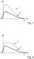
- FIG. 1shows with the dashed curve a desired brightness profile 1 of a strip-shaped light distribution over the angle ⁇ V , as it adjusts in advance of the light module on a perpendicular to the main emission of the light module arranged screen.
- This angleindicates at an intended use of the light module in a motor vehicle headlight in a motor vehicle at an angular deviation in the vertical direction of a vehicle longitudinal axis, which is located at the height of the horizon in front of the vehicle.
- the desired light distribution according to profile 1 below the horizonhas virtually no brightness, followed by a steep rise to a large maximum value which is just above the horizon, and a gradual drop to zero with increasing angle height above the horizon ,
- the continuous drawn curverepresents a brightness profile 2, as can be achieved with a single optical fiber branch, which will be described in more detail below and which is fed by a single light-emitting diode.
- This profile 2has a shape very similar to the desired profile 1, but remains below the values of the desired profile with its absolute values. This is because the luminous flux of the LED, which supplies light to a single branch, is too low.
- the shape of the achievable profilealso depends on the geometry and size of the light exit surface of the semiconductor light source used, which is arranged in a light module of a motor vehicle headlight directly in front of the light entry surface of the light guide branch. The achievable course is based on the use of a commercially available for headlights of motor vehicles semiconductor light source that provides a specific luminous flux.
- the desired profile 1would then result from the profile 2 without further changes of the arrangement if a light source of the same geometry but could be used correspondingly higher luminous flux. Such a light source is not available.
- the light guidemust be modified at least to such an extent that its light entry surface allows the light to be coupled in from two light sources.
- the light entrance surfacemust be so in particular be greater than if they would allow only the coupling of light from a single light source. Then inevitably changes the geometry of the light guide, for example, the ratio of its (unchanged) light exit surface to now become larger light entrance surface.
- An essential element of the inventionconsists in the described arrangement of at least two optical fiber branches, each of which is fed with its own semiconductor light source.
- Each of the at least two light guide branchesilluminates only a part of the vertical angular width of the desired light distribution.
- the profile 1corresponds to a strip, as it is generated in the context of the present invention with two branches per strip.
- the maximum of the profile 1is around about a quarter higher than the maximum of the profile produced with the same luminous flux 3.
- the outlet of the profile 1is also more pronounced.
- FIG. 3shows a light guide assembly 10 having at least a first optical fiber branch 12 and a second optical fiber branch 14.
- the first branch 12has a light entrance surface 12.1 and a light exit surface 12.2.
- the light exit surface 12.2is bounded by two narrow sides 12.3 and 12.4 and by two longitudinal sides 12.5 and 12.6.
- the second branch 14has a light entry surface 14.1 and a light exit surface 14.2.
- the light exit surface 14.2is bounded by two narrow sides 14.3 and 14.4 and by two longitudinal sides 14.5 and 14.6.
- the two branches 12, 14are arranged so that a narrow side 12.4 of the first branch 12 is arranged parallel and immediately adjacent to a narrow side 14.3 of the light exit surface 14.2 of the second branch 14.
- the narrow sides of the two branchesare the same length, while the longitudinal sides 14.5, 14.6 of the light exit surface of the second branch are longer than the longitudinal sides 12.5, 12.6 of the light exit surface of the second branch.
- Each branchhas two transport surfaces which delimit an optical fiber volume extending between the light entry surface and the light exit surface of each branch and which in turn are delimited by longitudinal sides of the light exit surfaces and internal light propagating in the optical fiber Total Reflections learns.
- FIG. 3shows a transport surface 12.7 of the first branch 12, which is bounded by the longitudinal side 12.6 of the light exit surface of the first branch. The limited by the other longitudinal side 12.5 further transport surface is in the FIG. 3 obscured by the optical fiber branch 12.
- a transport surfaceis an interface of a light guide, where internal total reflections take place.
- FIG. 3further shows a transport surface 14.7 of the second branch 14, which is delimited by the longitudinal side 14.6 of the light exit surface of the second branch. The limited by the other longitudinal side 14.5 further transport surface is in the FIG. 3 obscured by the light guide branch 14.
- transport surfacesdiffer from other transport surfaces of the respective light guide in that they are delimited by the longitudinal sides of the light exit surface of the branch, wherein in each case a transport surface is bounded by a longitudinal side.
- Other transport surfaces of the two branchesare each bounded by a narrow side of a respective branch.
- exit optics surface 12aDownstream of the light exit surface 12.2 of the first branch is an exit optics surface 12a in the beam path. Similarly, downstream of the light exit surface 14.2 of the second branch 14 in the beam path is associated with an exit optical surface 14.a. These exit optic surfaces are each convexly arched convexly away from the branches 12, 14 in the manner of a pillow. As a result, the light emerging from the light exit surfaces of the branches 12, 14 is directed toward a secondary optics (cf. FIG. 9 ) bundled.
- Sub-light beamswhich at their exit from the light exit surfaces of a branch have an undesirably large angle to Hauptabstrahlraum with which they would contribute, for example, to an undesirable bright lattice structure on the road, are preferably directed by the exit optics surfaces at the secondary optics. This also makes it possible to avoid unwanted, diffuse illumination of dark areas of the emitted light distribution.
- An exit optic surfacemay be an interface, that is, it may be a light exit surface of a branch, or it may be a light exit surface of exit optics separate from the associated branch.
- the branches and exit opticsare made of transparent material such as glass or PMMA or PC.
- the light guide branches 12, 14are characterized in particular by the fact that the transport surfaces have surface normals with a directional component which point more to a first of the two narrow sides of the branch than to a second of the two narrow sides of the branch, this for a plurality of all points of the transport surfaces applies to which incident on the associated light entry surface incident light.
- FIG. 4a cross section of the assembly 10, wherein this cross section of a cross section through the first branch 12 and through the second Branch 14 composed.
- the cross section of the first branch 12is limited by the transport surfaces 12.7, 12.8, 12.9 and 12.10, which in the FIG. 2 appear as cut edges.
- the transport surface 12.7is limited by the longitudinal side 12.6 transport surface.
- the transport surface 12.8is limited by the longitudinal side 12.5 transport surface.
- the transport surface 12.9is limited by the narrow side 12.3 transport surface.
- the transport surface 12.10is limited by the narrow side 12.4 transport surface.
- FIG. 2shows a surface normal 12.7n of the transport surface 12.7 and a surface normal 12.9n of the transport surface 12.9.
- the directional component 15 away from the transport surface 12.10which is bounded by the narrow side 12.4.
- the narrow side 12.4thus represents a second narrow side in the sense of claim 1.
- the cross section of the second branch 14is limited by the transport surfaces 14.7, 14.8, 14.9 and 14.10, which in the FIG. 4 appear as cut edges.
- the transport surface 14.7is limited by the longitudinal side 14.6 transport surface.
- the transport surface 14.8is limited by the longitudinal side 14.5 transport surface.
- the transport surface 14.9is limited by the narrow side 14.3 transport surface.
- the transport surface 14.10is the limited by the narrow side 14.4 transport surface.
- FIG. 2shows a surface normal 14.7n of the transport surface 14.7 and a surface normal 14.8n of the transport surface 14.8.
- the branches 12, 14 and their transport surfacesare designed so that the reference to the FIG. 4 shown relationships apply to a majority of all points of the transport surfaces, to which via the associated Light incident surface incoupled light is incident.
- the immediately adjacent and parallel narrow sides 12.4 and 14.3are a second narrow side 12.4 of the first branch 12 and a first narrow side 14.3 of the second branch 14.
- That the surface normal 14.7has a directional component 15, which has more to a first narrow side 14.9 of the two narrow sides of the branch 14 than to a second narrow side 14.10 of the narrow sides of the branch 14, at least for the majority, but preferably for all points of said lateral transport surfaces of the second branch 14 apply.
- That the surface normals 12.7, 12.9 of the first branchalso have such a directional component that points more to a first narrow side 12.9 of the two narrow sides of the branch 12 than to a second narrow side 12.10 of the narrow sides of the branch 12, should also in the case of the branch 12 at least for the plurality, but preferably apply to all points of the said lateral transport surfaces of the first branch 12.
- An essential difference between the cross-sections through the first, upper branch 12 and the second, lower branch 14is that the width difference of the narrow sides is greater in the case of the second branch 14 than in the case of the first branch 12. Another difference is that that the distance between the narrow sides of a branch is smaller in the case of the first branch 12 than in the case of the second branch 14. This is preferably true for all pairs of cross sections through the branches 12, 14, in which the cross sections of a pair have the same distance from their light entry surface and / or light exit surface.
- both differencescontribute to the fact that the surface normals of the second branch 14 are directed steeper to the wider narrow side 14. 9 of the second branch 14 than the surface normals of the first branch 12 are directed to the wider narrow side of the first branch 12.
- the light propagating in the second branch 14is concentrated comparatively more strongly in the vicinity of the broader narrow side of the second branch.
- the light propagating in the first branch 12is concentrated comparatively less strongly in the vicinity of the broader narrow side of the first branch 12.
- the transport surfaces 12.7, 12.8, 14.7, 14.8are limited in the illustrated embodiment by straight lines.
- the boundary linesare curved in other embodiments, so that the shape of the transport surfaces is not limited to flat surfaces.
- the surfacescan also be convex or concave. However, it is essential that the stated condition for the surface normals is observed.
- upper and lower transport surfaces 12.9, 12.10, 14.9, 14.10are preferably flat surfaces, which have a trapezoidal shape in the plan view, lies at the wider side on the light exit side of the respective branch. As a result, a concentration of the light is achieved on the stripe width.
- the longitudinal sidesmay also be concave or convex, but the width of the surface should increase continuously as the distance from the light entrance surface and the distance from the light exit surface increases.
- the second branch 14alone produces a stripe-shaped light distribution in which the brightness between the narrow sides of the light distribution changes comparatively more than is the case with the first branch.
- the first branchalone generates a strip-shaped light distribution in which the brightness between the narrow sides of the light distribution changes comparatively less than is the case in the second branch.
- Another differenceis that the length of the light strip produced by the second branch is greater than the length of the light strip produced by the first branch.
- a brightness maximumresults close to the first narrow side.
- the brightnessdecreases to a value which preferably corresponds to the value which results on the light exit surface of the second branch close to its first narrow side 14.3.
- the brightnessdecreases gradually and with increasing distance from the first narrow side 14.3 and increasing approach to the second narrow side of the light exit surface of the second branch, so that there is a soft brightness leakage.
- FIG. 5shows qualitatively vertical profiles of the brightness or light intensity I of the light distribution generated by the first branch, the light distribution generated by the second branch and the light distribution composed of these two light distributions over the angle ⁇ V .
- FIG. 5ashows the light distribution generated by the first branch 12.
- FIG. 5bshows the light distribution generated by the second branch 14 and
- FIG. 5cshows the total light distribution resulting as the sum of the individual light distributions.
- the first branch 12produces a pronounced maximum (high I values) of the brightness over a comparatively narrow range of approximately 1.5 degrees width.
- the zero-degree increase in brightnesscorresponds to a sharp cut-off. This is associated with the narrow side 12.3.
- This sharp cut-off linealso results in the cumulative light distribution according to FIG. 5c .
- a likewise still sharp light-dark boundaryalso generates the first branch on a side associated with the second narrow side 12.4.
- this light-dark boundarydoes not form, because the decrease in brightness of the light distribution generated by the first branch 12 there according to the brightness increase of the light distribution generated by the second branch 14 Figure 3c is compensated.
- the light distribution generated by the second light guide 14is in the FIG.
- the specified angle valuesare not random values but result from the desired values of the strip width, the strip height and the luminous fluxes of the available LEDs.
- the second light guide 14thus produces an extended brightness leakage, ie a continuous decrease in brightness, which is not perceived as a sharp cut-off line, towards a narrow side of the light exit surface of the light guide 14.
- the second light guide 14generates on the other narrow side of its light exit surface a comparatively sharply limited brightness maximum.
- the position of the bright strip above the horizon shown hereis characteristic of a light module that generates a high beam component of a light distribution of a motor vehicle headlight. It is understood, however, that the invention is also suitable for the production of low-beam light distributions. This results from the ability to create a sharp cut-off on one side of the brightness maximum.
- a low beam headlampcan be built according to the same principles.
- the stripesdo not have to go down but upwards. This arrangement results from the secondary optics projecting the assembly upside down and backwards into the apron (e.g., on a screen or lane).
- a bi-functional headlampwhich realizes both low beam and high beam function, can also be built according to the principles presented.
- branches 12 and 14are indeed, as FIG. 4 and the accompanying description is constructed according to the same principles. However, they also have differences that produce different effects: At least one of the branches, here the branch 12, is responsible for the maximum generation, and at least one other branch, here the branch 14, is responsible for the discontinuation generation.
- each of the adjacent light exit surfacesis assigned its own main exit optic surface, which is arranged behind the light exit surface in the light path.
- the main exit optic surface of the one light guideforms then in each case a secondary exit optics surface for the adjacent light guide.
- Light emerging from an edge region of a main exit surface and entering due to its propagation direction in a secondary exit surfacethere is preferably deflected so that it does not come to the secondary optics and thus does not contribute to a disturbingly strong brightening of the transition region between the two individual light distributions.
- the drive circuitis set up to jointly operate the light sources of a strip.
- Another embodimentprovides an individual control of these light sources, so that an additional variability of the light distribution to be generated is achieved.
- the brightness maximum generating light sourcemay be dimmed to highlight the edge illumination, or the edge illumination generating light source may be dimmed to further direct the driver's attention to the maximum brightly illuminated area. It is also possible to darken individual strips in order to avoid dazzling the oncoming traffic, which is located within the light cone just in the strip in question.
- the inventionallows profile scaling when doubling the LED light flux (for example, from 80Lm to 160Lm per pair of branches), at which all brightness values of the profile are also doubled.
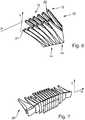
- FIG. 6shows an embodiment of a primary optics 20 with a plurality of arrangements of pairs of branches in a perspective view, in particular, the light entry surfaces 22, 24 are visible.
- the pairsWhen used as intended in a light module of a motor vehicle, the pairs are arranged in the horizontal direction H next to each other and the branches of a pair are arranged one above the other in the vertical direction V.
- the upper rowis formed by first branches 12.
- the lower rowis formed by second branches 14.
- a first branch 12 and a second branch 14together form an arrangement according to FIG. 3 which together produces a strip of light distribution.
- the six adjacent pairsare arranged laterally (along the horizontal H) at such a distance from each other that the stripe-shaped light distributions generated by the pairs touch immediately adjacent to each other or just merge into one another.
- the light exit surfaces of the individual branches and / or their associated primary optic surfacesare preferably arranged touching each other. This is achieved particularly preferably by an integral-material realization of the entire arrangement of here 6 pairs of two branches each. It is understood that the number of pairs may also be different from 6.
- convex Exit opticswith integrated into this arrangement. There are then no adjustment steps required to arrange the convex light exit surfaces in the correct position in front of the light exit surfaces of the branches and there are also no fastening means required to fix the positionally correct arrangement. This applies analogously to the branches themselves, which are fixed in an integral realization in the correct position arrangement zueiander in the one-piece arrangement.
- the first branches 12have a polygonal (eg 8-cornered) light entrance surface 22 which is slightly larger than the active, light-emitting LED surface and which is not rectangular.
- the first branch 12preferably has a cross-section, in which, if the reference numerals from the Fig. 4 an upper side 12.9 of a first branch 12 has approximately the same width as it also prevails at half the distance of the upper side 12.9 and the lower side 12.10 in the middle of the cross-sectional profile.
- the lower side 12.10is preferably somewhat narrower, so that the lower halves of the in the Fig. 4 constructed with the reference numerals 12.7 and 12.8 side surfaces an upside down roof profile (trapezoid) build. This is in the Fig. 4 shown in the form of dotted lines. This roof profile promotes the formation of concentration rather to the upper decoupling edge. Since the upside down rooftop in the first branches is not as pronounced as in the second branches 14, where this shape in the FIG. 6 is clearly visible, formed in the upper branches 12 is not a strong decaying Brightness outlet.
- each of the branches 12 and 14is larger than the light entrance surface 22 of the respective branch. This is an important prerequisite, so that the branch can exert a bundling effect on the coupled light flux.
- this cross sectionpixels is projected onto the roadway.
- the angle height of this projectionis 0.9 ° to 1.5 °, preferably about 1 °, for a first branch 12 on a perpendicular measuring wall.
- the light entry surfaces of the second branches 14are polygonal.
- the second branchesmay have the same number of sides as the first branches 12. It is essential, however, that the second branches extend in the vertical direction over a larger angular range than the first branches 12. This is true at least in the vicinity of the light exit surfaces of the branches, preferably but for the whole length of the branches.
- the thus formed, upside down roof profile of the second branches 14is therefore pointed down (Compare also FIG. 4 ). From the point of view of the LED, after coupling, a greater proportion of the coupled luminous flux strikes these inclined side surfaces, which in the FIG.
- This luminous flux componentis deflected to the wider narrow side of the branch.
- the wider narrow sideis preferably realized as a flat surface.
- the maximum brightnessis formed on the upper narrow coupling-out edge, that is to say on the broader narrow side of the light-emitting surface of the branch and an exponential curve of a similar outlet of the brightness in the direction of the narrower narrow side of the branch 14.
- the vertical extent of the light exit surfaces of the second branches 14is here significantly greater than the vertical extent of the light exit surfaces of the first branches 12.
- the horizontal width of the light exit surfacesis preferably constant within a pair of branches. Even with the first branches 12, the horizontal width of the respective light exit surface is the horizontal width of the associated light entry surface of this branch. This leads to a much stronger bundling, especially in the vertical direction, than in the horizontal direction.
- the angle height imaged by the secondary optics of a projection systemis preferably 4 degrees to 6 °, particularly preferably 5 °, for the strips produced by a second branch 14.
- optical fibers 12, 14, as proposed here in a particular arrangementallow scaling of the brightness profile as a function of luminous flux.
- the brightness maximum at the upper edge of the second light guide 14is adapted to the brightness value of the lower edge of the associated first branch 12.
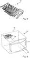
- the primary optics 26can be generated for a strip headlight. This can do that in the FIGS. 7 and 8th have shown appearance.
- primary opticsis understood to be the entirety of the branches and their associated exit optics, regardless of whether these elements form a structural unit connected in one piece with an integral substance or are composed of individual elements.
- FIG. 7a front view of a primary optics 26 of a strip-beam module, so in particular a view of the light exit surface.
- the primary optics 8centrally arranged pairs of two vertically superimposed branches. This achieves a high maximum brightness and a softness in the vertical direction.
- the vertical height of the further outward individual branchesis smaller than the vertical height of the further inner individual branches.
- FIG. 8shows a rear view of such a primary optics 26 of a strip high-beam module, ie in particular a view of the light entry surfaces.
- the connection of Fig. 7 and 8thshows in particular that each branch is associated with an associated exit optics.
- FIG. 9schematically shows a motor vehicle headlight 30th with a housing 32, which is covered by a transparent cover 34 and in which an embodiment of a light module according to the invention is arranged.
- the light moduleis a projection module.
- Thishas in particular a primary optics 28.
- the primary optichere corresponds to the subject of FIGS. 7 and 8th ,
- the light exit surfaces of the exit optics of this primary opticsare at a distance of a focal length of a secondary optics 36 in the direction of the optical axis of the secondary optics in the light path in front of the secondary optics.
- the secondary opticsis preferably produced as a lens made of transparent material, in particular of glass or plastic, in particular PC or PMMA.
- the secondary opticsis produced as a double-layer achromat from both plastics.
- the secondary opticsform the internal light distribution, which adjusts itself to the entire light exit surface of the exit optics, as external light distribution into the apron of the headlamp.
- the primary optics and the secondary opticsare arranged relative to one another in such a way that the primary optics concentrate the light bundle exiting their exit optics onto the secondary optics so that as little light as possible passes the secondary optics.
- the lightemanates from LEDs, wherein preferably one LED is arranged in front of each light entry surface of one of the branches.
- secondary optics secondary optics having achromatic propertiesare preferably used, on the lens surface of which scattering microstructures are regularly or irregularly distributed.
Landscapes
- Engineering & Computer Science (AREA)
- General Engineering & Computer Science (AREA)
- Physics & Mathematics (AREA)
- Microelectronics & Electronic Packaging (AREA)
- Optics & Photonics (AREA)
- Mathematical Physics (AREA)
- Non-Portable Lighting Devices Or Systems Thereof (AREA)
- Planar Illumination Modules (AREA)
Description
Translated fromGermanDie Erfindung betrifft ein Lichtmodul für einen Kraftfahrzeugscheinwerfer nach dem Oberbegriff des Anspruchs 1.The invention relates to a light module for a motor vehicle headlight according to the preamble of claim 1.
Ein solches Lichtmodul ist aus der
Die Zweige sind zusammen mit einer Vielzahl weiterer Zweige Bestandteile einer Primäroptik. Jede Lichteintrittsfläche weist eine LED auf, deren Licht in den Zweig eingekoppelt und über die Lichtaustrittsfläche ausgekoppelt wird. Die Lichtaustrittsflächen sind matrixartig angeordnet, so dass die Summe der Lichtaustrittsflächen eine pixelartig zusammengesetzte leuchtende Fläche bildet, deren Form durch Ein- und Ausschalten von LEDs variiert werden kann. Die leuchtende Fläche liegt im Inneren des Scheinwerfers als innere Lichtverteilung im Abstand einer Brennweite einer Sekundäroptik vor derselben und wird von dieser als äußere Lichtverteilung in das Vorfeld des Scheinwerfers projiziert. Das bekannte Lichtmodul wird im Folgenden auch als Matrix-Lichtmodul bezeichnet.The branches, together with a large number of other branches, are components of a primary optic. Each light entry surface has an LED whose light is coupled into the branch and coupled out via the light exit surface. The light exit surfaces are arranged in a matrix, so that the sum of the light exit surfaces forms a pixel-like composite luminous surface whose shape can be varied by switching on and off of LEDs. The luminous surface lies in the interior of the headlamp as an internal light distribution at a distance of a focal length of a secondary optics in front of the same and is projected by this as an external light distribution in the apron of the headlamp. The known light module is also referred to below as the matrix light module.
Bei einer bestimmungsgemäßen Verwendung des Lichtmoduls in einem Kraftfahrzeugscheinwerfer ergibt sich die äußere Lichtverteilung auf der Fahrbahn damit als ein Bild der pixelartig zusammengesetzten, im Inneren des Scheinwerfers liegenden inneren Lichtverteilung, die auf der Lichtaustrittsfläche der Primäroptik entsteht. Durch Einschalten und Ausschalten einzelner LEDs und damit einzelner Pixel erscheinen auch die Bilder der Pixel in der äußeren Lichtverteilung entweder hell oder dunkel. Das Ausschalten oder Dimmen einzelner LEDs oder Gruppen von LEDs erlaubt damit zum Beispiel eine gezielte Verringerung der Beleuchtung in Bereichen, in denen der Gegenverkehr geblendet werden könnte.When the light module is used as intended in a motor vehicle headlight, the external light distribution on the roadway thus results as an image of the pixel-like internal light distribution inside the headlight which arises on the light exit surface of the primary optics. By switching on and off individual LEDs and thus individual pixels, the images of the pixels in the outer light distribution appear either light or dark. The Switching off or dimming individual LEDs or groups of LEDs thus allows, for example, a targeted reduction in the lighting in areas in which the oncoming traffic could be dazzled.
Als bekannt vorausgesetzt werden auch Lichtmodule, die Lichtverteilungen mit nebeneinander liegenden streifenförmigen Einzellichtverteilungen erzeugen. Jeder Streifen wird dabei von einem Lichtleiterzweig und einer Lichtquelle erzeugt. Im Vergleich mit dem Matrix-Lichtmodul ersetzt hier jeder Lichtleiterzweig eine Spalte von Lichtleiterzweigen der Matrix.Be assumed to be known and light modules that produce light distributions with adjacent strip-shaped individual light distributions. Each strip is generated by an optical fiber branch and a light source. In comparison with the matrix light module, each light guide branch here replaces a column of light guide branches of the matrix.
Die angestrebte horizontale Winkelauflösung eines solchen Lichtmoduls, das streifenförmige Lichtverteilungen erzeugt, liegt z.B. zwischen 1,0° und 1,5° in der Horizontalen, wobei sich diese Richtungsangabe auf die bestimmungsgemäße Verwendung des Scheinwerfers in einem Kraftfahrzeug bezieht. Diese Begrenzung ergibt sich in Verbindung mit den in der Praxis für die Verwendung in Kraftfahrzeugscheinwerfern zur Verfügung stehenden Lichtquellen, die in Bezug auf ihre Geometrie feste Abmessungen besitzen und auch nur einen begrenzten Lichtstrom abgeben. Diese Forderung grenzt bereits die Variabilität des optischen Systems ein.The desired horizontal angular resolution of such a light module which generates strip-shaped light distributions is e.g. between 1.0 ° and 1.5 ° in the horizontal, this direction refers to the intended use of the headlight in a motor vehicle. This limitation arises in connection with the light sources available in practice for use in motor vehicle headlights, which have fixed dimensions in terms of their geometry and also emit only a limited luminous flux. This requirement already limits the variability of the optical system.
Die für die genannte Verwendung bevorzugten High-Power-LEDs haben eine leuchtende und damit aktive Lichtaustrittsfläche mit quadratischer Form und einer Größe von ca.0,5mm2. Die aktive Fläche ist dabei unabhängig vom abgegebenen Lichtstrom konstant. Gleichermaßen konstant ist auch die LED-Abstrahlcharakteristik, also die Winkelverteilung des abgestrahlten Lichtes. In der Regel handelt es sich um eine sogenannte Lambert-Charakteristik. Der sogenannte Warm-Lichtstrom im LED-Dauerbetrieb beträgt bei einem maximal zulässigen elektrischen Betriebsstrom z.B. ca. 80 Lumen. Es ist zwar zu erwarten, dass der Warmlichtstrom in Zukunft in begrenztem Maße zunehmen wird. In Bezug auf die vorliegende Erfindung ist der zur Verfügung stehende Lichtstrom jedoch als begrenzt zu betrachten.The preferred high-power LEDs for this use have a luminous and thus active light-emitting surface with a square shape and a size of approx. 0.5 mm2 . The active area is constant regardless of the emitted luminous flux. Equally constant is the LED emission characteristic, ie the angular distribution of the radiated light. As a rule, it is a so-called Lambert characteristic. The so-called warm luminous flux in LED continuous operation is at a maximum allowable electrical operating current, for example, about 80 lumens. It is to be expected that the heat flux will increase to a limited extent in the future. However, with respect to the present invention, the available luminous flux is considered to be limited.
Aus Kostengründen und aus Gründen der Zuverlässigkeit wird allgemein angestrebt, dass die Zahl der Lichtquellen eines Lichtmoduls möglichst gering sein sollte. Lichtmodule, die streifenförmige Lichtverteilungen erzeugen (im folgenden auch als Streifen-Lichtmodule bezeichnet), werden daher gegenüber Lichtmodulen, die matrixartig zusammengesetzte Lichtverteilungen erzeugen, bevorzugt. Um mit einem Streifen-Lichtmodul und damit möglichst wenig LEDs genügend Lichtstrom auf die Fahrbahn zu projizieren, um damit Lichtverteilungen mit vorgegeben hohen Maximalwerten für die Helligkeit und einer vorgegebenen Änderung der Helligkeit längs einer vertikalen Winkelskala zu erzeugen, ist auch eine hohe Lichtübertragungseffizienz erforderlich. Dabei wird hier unter der Lichtübertragungseffizienz zum Beispiel der aus einer Sekundäroptik austretende Lichtstrom nach seiner Normierung auf den in die Primäroptik eintretenden Lichtstrom verstanden.For reasons of cost and reliability, it is generally desired that the number of light sources of a light module should be as low as possible. Light modules which generate strip-shaped light distributions (also referred to below as strip light modules) are therefore preferred over light modules which generate matrix-like light distributions. In order to project sufficient luminous flux onto the roadway with a strip light module and therefore as few LEDs as possible in order to produce light distributions with predetermined maximum brightness values and a given change in brightness along a vertical angle scale, high light transmission efficiency is also required. In this case, the luminous transmission efficiency is understood to mean, for example, the luminous flux emerging from a secondary optic after its normalization to the luminous flux entering the primary optics.
Vor diesem Hintergrund besteht eine Aufgabe der vorliegenden Erfindung in der Angabe eines Lichtmoduls der eingangs genannten Art, das eine Erzeugung von in vertikaler Richtung streifenförmigen Lichtverteilungen mit einer geringen Anzahl von Lichtquellen erlaubt. Die streifenförmige Lichtverteilung soll eine erste Schmalseite aufweisen, an der ein ausgeprägtes Maximum der Helligkeit liegt. Davon ausgehend und auf die gegenüberliegende zweite Schmalseite der streifenförmigen Lichtverteilung hin zulaufend soll die Helligkeit abnehmen. Der Gradient der Beleuchtungsstärke oder Helligkeit soll dabei auf der der ersten Schmalseite der Lichtverteilung zugewandten Seite des Maximums viel steiler als auf der der zweiten Schmalseite zugewandten Seite des Maximums sein. Im Ergebnis soll sich ein beleuchteter Streifen mit einer scharfen Hell-Dunkel-Grenze an der ersten Schmalseite, einem sich daran anschließenden Bereich maximaler Helligkeit und einer auf der anderen Seite des Maximums weich und kontinuierlich auslaufenden Helligkeit, also einer mit zunehmendem Abstand von der scharfen Hell-Dunkelgrenze und dem Helligkeitsmaximum kontinuierlich über die Streifenlänge geringer werdenden Helligkeit einstellen. Dabei soll die Helligkeit mit zunehmendem Abstand vom Maximum überproportional zur Abstandszunahme abnehmen und entsprechend in umgekehrter Richtung von der zweiten Schmalseite ausgehend in Richtung zum Maximum hin überproportional zum Abstand von der zweiten Schmalseite zunehmen.Against this background, an object of the present invention is to provide a light module of the type mentioned, which is a generation of vertically striped strip light distributions with a small number allowed by light sources. The strip-shaped light distribution should have a first narrow side, at which a pronounced maximum of the brightness is. Starting from this and tapering towards the opposite second narrow side of the strip-shaped light distribution, the brightness should decrease. The gradient of the illuminance or brightness should be much steeper on the side of the maximum facing the first narrow side of the light distribution than on the side of the maximum facing the second narrow side. The result is an illuminated strip with a sharp cut-off on the first narrow side, an adjoining region of maximum brightness and on the other side of the maximum soft and continuous expiring brightness, so with increasing distance from the sharp light - Set the dark limit and the brightness maximum continuously over the strip length decreasing brightness. The brightness should decrease disproportionately to increasing distance with increasing distance from the maximum and increase correspondingly in the reverse direction from the second narrow side in the direction of the maximum out of proportion to the distance from the second narrow side.
Diese Aufgabe wird mit den Merkmalen des Anspruchs 1 gelöst. Die vorliegende Erfindung unterscheidet sich von dem bekannten Matrix-Lichtmodul dadurch, dass die genannten Transportflächen jedes Zweiges Flächennormalen aufweisen, die eine Richtungskomponente aufweisen, die mehr zu einer ersten der beiden Schmalseiten des Zweiges als zu einer zweiten der beiden Schmalseiten des Zweiges weist. Dies gilt für eine Mehrzahl aller Punkte der Transportflächen, auf die über die zugehörige Lichteintrittsfläche eingekoppeltes Licht einfällt. Wesentlich ist auch, dass die unmittelbar benachbart und parallel zueinander liegenden Schmalseiten eine zweite Schmalseite des ersten Zweiges und eine erste Schmalseite des zweiten Zweiges sind.This object is achieved with the features of claim 1. The present invention differs from the known matrix light module in that the said transport surfaces of each branch have surface normals having a directional component facing more to a first of the two narrow sides of the branch than to a second of the two narrow sides of the branch. This applies to a plurality of all points of the transport surfaces, to which incident on the associated light entry surface incident light. It is also essential that the immediately adjacent and mutually parallel narrow sides are a second narrow side of the first branch and a first narrow side of the second branch.
Bei internen Totalreflexionen liegen ein in einem Punkt einfallender Strahl, das Lot der Reflexionsfläche in diesem Punkt, bzw. die Flächennormale in diesem Punkt, und der von diesem Punkt ausgehende reflektierte Strahl immer in ein und derselben Ebene. Das bedeutet, dass man bei vorgegebenem Einfallswinkel die Richtung des reflektierten Strahls durch die Neigung der reflektierenden Fläche und damit durch die Ausrichtung der Flächennormalen steuern kann.In the case of total internal reflections, a ray incident at a point, the perpendicular of the reflection surface at this point, or the surface normal at that point, and the reflected ray emanating from this point always lie in one and the same plane. This means that for a given angle of incidence one can control the direction of the reflected beam by the inclination of the reflecting surface and thus by the orientation of the surface normal.
Dadurch, dass die Flächennormalen derjenigen zwei Transportflächen jedes Zweiges, die von den Längsseiten der Lichtaustrittsfläche des Zweiges begrenzt werden, eine Richtungskomponente aufweisen, die mehr zu einer ersten der beiden Schmalseiten des Zweiges als zu einer zweiten der beiden Schmalseiten des Zweiges weist, wird das Licht bei der Reflexion bevorzugt in Richtung zur ersten Schmalseite umgelenkt.Characterized in that the surface normals of those two transport surfaces of each branch, which are delimited by the longitudinal sides of the light exit surface of the branch, have a directional component which has more to a first of the two narrow sides of the branch than to a second of the two narrow sides of the branch, the light in the reflection preferably deflected in the direction of the first narrow side.
Dadurch, dass dies für eine Mehrzahl aller Punkte der Transportflächen gilt, ergeben sich in der von der ersten Schmalseite begrenzten Hälfte der Lichtaustrittsfläche höhere Intensitäten als in der von der zweiten Schmalseite begrenzten Hälfte.Because this applies to a plurality of all points of the transport surfaces, higher intensities result in the half of the light exit surface defined by the first narrow side than in the half bounded by the second narrow side.
Dadurch, dass eine Schmalseite des ersten Zweiges parallel und unmittelbar benachbart zu einer Schmalseite der Lichtaustrittsfläche des zweiten Zweiges angeordnet ist, sind auch die Bilder der Lichtaustrittsflächen in der äußeren Lichtverteilung entsprechend aneinander angrenzend angeordnet.Characterized in that a narrow side of the first branch is arranged parallel and immediately adjacent to a narrow side of the light exit surface of the second branch, and the images of the light exit surfaces in the arranged according to the outer light distribution adjacent to each other.
Dadurch, dass die unmittelbar benachbart und parallel zueinander liegenden Schmalseiten eine zweite Schmalseite des ersten Zweiges und eine erste Schmalseite des zweiten Zweiges sind, ergibt sich eine Anordnung, bei der ein dunklerer Bereich der Lichtaustrittsfläche des ersten Zweiges an einen helleren Bereich der Lichtaustrittsfläche des zweiten Zweiges angrenzt. Dabei sind die aneinander angrenzenden Bereiche dort, wo sie aneinander angrenzen, bevorzugt gleich hell. Ein Helligkeitsmaximum der einen Fläche trifft also auf ein Helligkeitsminimum der anderen Fläche, wobei das Maximum der einen Fläche den gleichen Wert hat wie das Minimum der anderen Fläche.Characterized in that the immediately adjacent and parallel narrow sides are a second narrow side of the first branch and a first narrow side of the second branch, there is an arrangement in which a darker region of the light exit surface of the first branch to a lighter region of the light exit surface of the second branch borders. In this case, the adjoining regions preferably have the same brightness where they adjoin one another. A brightness maximum of one surface thus meets a brightness minimum of the other surface, the maximum of one surface having the same value as the minimum of the other surface.
Dadurch, dass die Schmalseiten der Lichtaustrittsflächen der beiden Zweige gleich lang sind, während die Längsseiten der Lichtaustrittsfläche des zweiten Zweiges länger sind als die Längsseiten der Lichtaustrittsfläche des zweiten Zweiges, ist die Lichtaustrittsfläche des zweiten Zweiges größer als die Lichtaustrittsfläche des ersten Zweiges. Entsprechend wird der in den ersten Zweig eingekoppelte Lichtstrom auf eine kleinere Lichtaustrittsfläche verteilt, als der in den zweiten Zweig eingekoppelte Lichtstrom. Werden jeweils gleiche Lichtquellen benutzt, kann mit der kleineren Lichtaustrittsfläche des ersten Zweiges eine größere Maximalhelligkeit erzeugt werden als mit der größeren Lichtaustrittsfläche des zweiten Zweiges.Characterized in that the narrow sides of the light exit surfaces of the two branches are the same length, while the longitudinal sides of the light exit surface of the second branch are longer than the longitudinal sides of the light exit surface of the second branch, the light exit surface of the second branch is greater than the light exit surface of the first branch. Accordingly, the light flux coupled into the first branch is distributed to a smaller light exit surface than the luminous flux coupled into the second branch. If the same light sources are used in each case, a larger maximum brightness can be generated with the smaller light exit surface of the first branch than with the larger light exit surface of the second branch.
Insgesamt liefert die Anordnung mit den beiden Lichtleiterzweigen damit eine streifenförmige Lichtverteilung, die in der Längsrichtung des Streifens von der ersten Schmalseite der Lichtaustrittsfläche des ersten Zweiges und der zweiten Schmalseite der Lichtaustrittsfläche des zweiten Zweiges begrenzt wird. Dabei nimmt die Helligkeit von einem ausgeprägten Maximum ausgehend, das an der ersten Schmalseite liegt, und auf die gegenüberliegende zweite Schmalseite hin zulaufend, ab. Der Gradient der Beleuchtungsstärke ist dabei auf der der ersten Schmalseite zugewandten Seite des Maximums viel steiler als auf der der zweiten Schmalseite zugewandten Seite des Maximums. Im Ergebnis stellt sich ein beleuchteter Streifen mit einer scharfen Hell-Dunkel-Grenze an der ersten Schmalseite und einer weich und kontinuierlich auslaufenden Helligkeit auf der anderen Seite des Maximums ein. Die Helligkeit nimmt dabei mit zunehmendem Abstand vom Maximum überproportional zur Abstandszunahme ab. Entsprechend nimmt sie in umgekehrter Richtung von der zweiten Schmalseite ausgehend in Richtung zum Maximum überproportional zum Abstand von der zweiten Schmalseite zu.Overall, the arrangement with the two light guide branches thus provides a strip-shaped light distribution, in the longitudinal direction of the strip from the first narrow side of the light exit surface of the first Branch and the second narrow side of the light exit surface of the second branch is limited. The brightness decreases starting from a pronounced maximum, which lies on the first narrow side and tapering towards the opposite second narrow side. The gradient of the illuminance is much steeper on the side of the maximum facing the first narrow side than on the side of the maximum facing the second narrow side. The result is an illuminated strip with a sharp light-dark boundary on the first narrow side and a smooth and continuous outgoing brightness on the other side of the maximum. The brightness decreases with increasing distance from the maximum disproportionate to the increase in distance. Accordingly, it increases in the opposite direction from the second narrow side, starting in the direction of the maximum overproportional to the distance from the second narrow side.
Insgesamt erlaubt die vorliegende Erfindung bei einer Nebeneinanderanordnung solcher Lichtleiteranordnungen mit einem ersten Lichtleiterzweig und einem zweiten Lichtleiterzweig in einem Lichtmodul die Erzeugung einer aus einzelnen Streifen zusammengesetzten Lichtverteilung, die ein ausgeprägtes Intensitätsmaximum an einer Schmalseite des Streifens und einen kontinuierlichen Auslauf der Intensität, also eine kontinuierliche Abnahme der Helligkeit des Streifens in Richtung zur anderen Schmalseite aufweist.Overall, the present invention allows for juxtaposition of such light conductor arrangements with a first light guide branch and a second light guide branch in a light module, the generation of a composite of individual stripes light distribution, a pronounced intensity maximum on a narrow side of the strip and a continuous outlet of the intensity, ie a continuous decrease the brightness of the strip toward the other narrow side has.
Diese Vorteile werden mit einer Zahl von Lichtquellen erzielt, die insbesondere kleiner ist als die Zahl der Lichtquellen, die für ein Matrixlichtmodul der eingangs genannten Art benötigt werden, wenn dieses eine mit Blick auf das Maximum und den Auslauf vergleichbare Lichtverteilung erzeugen soll.These advantages are achieved with a number of light sources, which in particular is smaller than the number of light sources needed for a matrix light module of the type mentioned, if this one with a view to produce comparable light distribution to the maximum and the outlet.
In einer konkreten Realisierung erlaubt die Erfindung die Erzeugung streifenförmiger Lichtverteilungen unter den eingangs genannten Randbedingungen mit einer ausgeprägten Hell-Dunkel-Grenze mit einem Helligkeitsmaximum von mehr als 120 Lux und einem sich bis auf eine vertikale Winkelbreite von bis zu 6° erstreckenden Helligkeitsauslauf.In a concrete implementation, the invention allows the generation of strip-shaped light distributions under the boundary conditions mentioned above with a pronounced cut-off with a brightness maximum of more than 120 lux and a brightness outlet extending up to a vertical angular width of up to 6 °.
Ein weiterer Vorteil der vertikal gestreckten Lichtaustrittsfläche liegt darin, dass die in der Ausbreitungsrichtung des Lichtes der Primäroptik nachfolgende Sekundäroptik in dieser vertikalen Richtung kleiner sein kann als dies ohne die vertikale Streckung der Lichtaustrittsfläche der Primäroptik der Fall wäre. Dies ergibt sich aus dem Etandue-Erhaltungssatz. In der angegebenen konkreten Realisierung konnte als Folge der durch die Primäroptik verbesserten vertikalen Lichtbündelung die vertikale Höhe einer Sekundäroptik auf 40 mm verringert werden. Ohne die Erfindung sind dagegen eher Werte von 60 bis 80 mm üblich.A further advantage of the vertically elongated light exit surface is that the secondary optics following in the direction of propagation of the primary optic light can be smaller in this vertical direction than would be the case without the vertical extension of the primary optic light exit surface. This follows from the Etandue conservation law. In the given concrete realization, the vertical height of a secondary optic could be reduced to 40 mm as a consequence of the vertical light bundling improved by the primary optics. On the other hand, values of 60 to 80 mm are more common without the invention.
Die lichtverteilungsformende Vorsatzoptik mit den entsprechend der vorliegenden Erfindung optimierten Lichtleiterzweigen besitzt eine hohe Lichtübertragungseffizienz. Dabei sind für ein System aus Primäroptik und Sekundäroptik, also ohne Abdeckscheibe, Werte von 50% bis über 60% erzielbar. D.h. 50% bis über 60% der in die Primäroptik eingekoppelten Lichtenergie treten auch wieder aus der Sekundäroptik aus. Der Wert hängt von den Seitenverhältnissen der Lichtaustrittsfläche (Verhältnis der Längen der Schmalseiten zu den Längen der Längsseiten) und der Lage des Lichtleiters bezüglich der optischen Achse der Sekundäroptik ab.The light distribution forming optical head with the optical fiber branches optimized according to the present invention has a high light transmission efficiency. In this case, values of 50% to more than 60% can be achieved for a system of primary optics and secondary optics, that is to say without a cover disc. This means that 50% to more than 60% of the light energy coupled into the primary optics also emerge again from secondary optics. The value depends on the aspect ratios of the light exit surface (ratio of the lengths of the narrow sides to the lengths of the long sides) and the position of the light guide with respect to the optical axis secondary optics.
Als vorteilhafte Folge der hohen Effizienz der Lichtübertragung in den Zweigen/der Primäroptik sind weniger LEDs erforderlich, um regelkonforme Lichtverteilungen zu erzeugen.As an advantageous consequence of the high efficiency of the light transmission in the branches / the primary optics fewer LEDs are required to produce rule-compliant light distributions.
Für die Realisierung einer Abblendlicht-Lichtfunktion und einer Fernlicht-Lichtfunktion sind bei einem Matrix-Lichtmodul nach der eingangs genannten
Diese Vorteile hängen eng zusammen mit einer sehr hohen Effizienz der im Rahmen der Erfindung verwendeten Lichtleiterzweige. Diese hohen Effizienzwerte ergeben sich daraus, dass die Primäroptik, beziehungsweise die einzelnen Lichtleiterzweige der Primäroptik, das in ihnen propagierende Licht gut konzentrieren, um aus der Lambert'-schen Lichtverteilung einer LED ein Bündel zu erzeugen, das auf eine vergleichsweise kleine Lichteintrittsfläche einer Sekundäroptik mit z.B. 40 mm Höhe konzentriert ist.These advantages are closely related to the very high efficiency of the fiber optic branches used in the invention. These high efficiency values result from the fact that the primary optics, or rather the individual optical fiber branches of the primary optics, concentrate the light propagating in them in order to produce a bundle from the Lambert light distribution of an LED, which has a comparatively small light entrance surface of secondary optics eg 40 mm in height is concentrated.
Die für dieses konkrete Beispiel erforderliche Bündelung gelingt nur, wenn die Lichtleiter nach dem bereits vorgestellten Prinzip aufgebaut sind und die Schmalseiten der Lichtaustrittsflächen der Zweige eine horizontale Breite von ca. 1,9 mm bis 2,1 mm haben. Da die Winkelauflösung vorgegeben ist, ergibt sich auch ein bevorzugter Brennweitenbereich für die Sekundäroptik, der in diesem konkreten Beispiel zwischen 90mm und 100mm liegt.The bundling required for this concrete example succeeds only if the light guides are constructed according to the principle already presented and the narrow sides of the light exit surfaces of the branches have a horizontal width of approximately 1.9 mm to 2.1 mm. Since the angular resolution is predetermined, there is also a preferred focal length range for the secondary optics, which lies in this particular example between 90mm and 100mm.
Würde man in diesem konkreten und realistischen Beispiel eine Lösung auf der Basis von mit Metall bedampften Reflektoren als Primäroptiken suchen, käme man nicht zum Ziel. Eine solche Primäroptik kann den gestellten Anforderungen nicht genügen, da Metallbedampfte Reflektoren Licht absorbieren (ca. 15% pro Reflexion) und bei mehrfacher Reflexion schnell einen Großteil des Lichtflusses absorbieren und in Wärme umwandeln. Das führt über kurz oder lang zur Zerstörung der Reflektoren durch Überhitzung und verhindert, dass die gewünschten Helligkeitswerte auch nur ansatzweise erreicht werden. Nur hochtransparente TIR-basierte (TIR = totale interne Reflexion) Primäroptiken sind in der Lage, den LED-Lichtstrom mit der erfoderlichen Effizienz in den geforderten Winkelbereich zu bündeln.If, in this concrete and realistic example, you were looking for a solution based on metal-coated reflectors as primary optics, you would not reach your goal. Such a primary optics can not meet the requirements, since metal-coated reflectors absorb light (about 15% per reflection) and with multiple reflection quickly absorb much of the light flux and convert it into heat. This sooner or later leads to the destruction of the reflectors due to overheating and prevents the desired brightness values from being reached even in their beginnings. Only highly transparent TIR-based (TIR = total internal reflection) primary optics are able to bundle the LED luminous flux with the required efficiency into the required angular range.
Wenn es um winkelaufgelöste Streifen- oder Matrix-Scheinwerfern geht, führt daher kein Weg an einer Lichtleiter-basierten Primäroptik vorbei. Wie bereits ausgeführt wurde, ergeben sich dann bereits durch die LED-Größe Beschränkungen auf bestimmte geometrische Primäroptik-Maße.When it comes to angle-resolved strip or matrix headlights, there is no way around fiber-optic based primary optics. As already stated, the size of the LED already results in restrictions on certain geometrical primary optics dimensions.
Die vorliegende Erfindung liefert eine Lösung, die das Potential aufweist, zuvor unvereinbaren Rahmenbedingungen zu genügen und neuen Herausforderungen begegnen zu können.The present invention provides a solution that has the potential to meet previously incompatible framework conditions and to meet new challenges.
Weitere Vorteile ergeben sich aus den abhängigen Ansprüchen, der Beschreibung und den beigefügten Figuren.Further advantages will be apparent from the dependent claims, the description and the attached figures.
Es versteht sich, dass die vorstehend genannten und die nachstehend noch zu erläuternden Merkmale nicht nur in den jeweils angegebenen Kombinationen, sondern auch in anderen Kombinationen oder in Alleinstellung verwendbar sind, ohne den Rahmen der vorliegenden Erfindung zu verlassen.It is understood that the features mentioned above and those yet to be explained not only in the each specified combinations, but also in other combinations or alone, without departing from the scope of the present invention.
Es zeigen, jeweils in schematischer Form:
- Figur 1
- ein erwünschtes und ein mit einer einzelnen LED erzielbares Helligkeitsprofil einer streifenförmigen Lichtverteilung;
Figur 2- ein mit einer nicht erfindungsgemäßen Lösung erzielbares Helligkeitsprofil;
Figur 3- eine Lichtleiteranordnung mit wenigstens einem erstem Lichtleiterzweig und einem zweiten Lichtleiterzweig;
- Figur 4
- einen Schnitt durch die Anordnung nach
Figur 1 ; - Figur 5
- vertikale Profile der Helligkeit I der vom ersten Zweig erzeugten Lichtverteilung, der vom zweiten Zweig erzeugten Lichtverteilung und einer aus diesen beiden Lichtverteilungen zusammengesetzten Lichtverteilung;
- Figur 6
- ein Ausführungsbeispiel einer Primäroptik mit mehreren Anordnungen von Zweigpaaren in einer perspektivischen Ansicht aus einer ersten Blickrichtung;
Figur 7- eine Vorderansicht von einem Streifen-Fernlichtmodul, also insbesondere eine Ansicht der Lichtaustrittsfläche;
- Figur 8
- eine Rückansicht eines solchen Streifen-Fernlichtmoduls, also insbesondere eine Ansicht der Lichteintrittsflächen, und
- Figur 9
- schematisch einen Kraftfahrzeugscheinwerfer, der eine Ausgestaltung eines erfindungsgemäßen Lichtmoduls aufweist.
- FIG. 1
- a desired and a single LED achievable brightness profile of a striped light distribution;
- FIG. 2
- a brightness profile achievable with a noninventive solution;
- FIG. 3
- a light guide assembly having at least a first optical fiber branch and a second optical fiber branch;
- FIG. 4
- a section through the arrangement according to
FIG. 1 ; - FIG. 5
- vertical profiles of the brightness I of the light distribution generated by the first branch, the light distribution generated by the second branch and a light distribution composed of these two light distributions;
- FIG. 6
- an embodiment of a primary optics with multiple arrangements of pairs of branches in a perspective view from a first viewing direction;
- FIG. 7
- a front view of a strip high beam module, so in particular a view the light exit surface;
- FIG. 8
- a rear view of such a strip high-beam module, so in particular a view of the light entry surfaces, and
- FIG. 9
- schematically a motor vehicle headlamp, which has an embodiment of a light module according to the invention.
Sowohl gleiche als auch funktional einander entsprechende Elemente werden in allen Figuren mit jeweils gleichen Bezugszeichen bezeichnet.Both identical and functionally corresponding elements are denoted by the same reference numerals in all figures.
Der Abfall erfolgt kontinuierlich und mit zunehmendem Abstand vom Horizont überproportional, was sich am teilweise linksgekrümmten Verlauf des Profils zeigt.The waste occurs continuously and disproportionately with increasing distance from the horizon, which is due to the partially left-curved profile of the profile shows.
Der durchgezogen gezeichnete Verlauf repräsentiert ein Helligkeitsprofil 2, wie es mit einem einzelnen Lichtleiterzweig, der weiter unten noch näher beschrieben wird und der von einer einzelnen Leuchtdiode gespeist wird, erzielt werden kann.The continuous drawn curve represents a
Dieses Profil 2 weist eine dem gewünschten Profil 1 sehr ähnliche Form auf, bleibt aber mit seinen Absolutwerten unter den Werten des gewünschten Profils. Dies liegt daran, dass der Lichtstrom der LED, die einen einzelnen Zweig mit Licht speist, zu gering ist. Die Form des erzielbaren Profils hängt auch von der Geometrie und Größe der Lichtaustrittsfläche der verwendeten Halbleiterlichtquelle ab, die in einem Lichtmodul eines Kraftfahrzeugscheinwerfers unmittelbar vor der Lichteintrittsfläche des Lichtleiterzweiges angeordnet ist. Der erzielbare Verlauf basiert auf der Verwendung einer für Scheinwerfer von Kraftfahrtzeugen handelsüblichen Halbleiterlichtquelle, die einen bestimmten Lichtstrom liefert.This
Das erwünschte Profil 1 würde sich aus dem Profil 2 ohne weitere Änderungen der Anordnung dann ergeben, wenn eine Lichtquelle gleicher Geometrie aber entsprechend höherem Lichtstrom verwendet werden könnte. Eine solche Lichtquelle steht aber nicht zur Verfügung.The desired profile 1 would then result from the
Wenn man, um einen entsprechend größeren Lichtstrom bereitzustellen, an Stelle einer LED zwei LEDs verwendet, muss man den Lichtleiter zumindest soweit abändern, dass seine Lichteintrittsfläche die Lichteinkopplung von zwei Lichtquellen erlaubt. Die Lichteintrittsfläche muss also insbesondere größer sein, als wenn sie nur die Einkopplung von Licht einer einzigen Lichtquelle erlauben würde. Dann verändert sich zwangsläufig die Geometrie des Lichtleiters, zum Beispiel das Verhältnis seiner (unveränderten) Lichtaustrittsfläche zur nun größer gewordenen Lichteintrittsfläche.If, in order to provide a correspondingly greater luminous flux, two LEDs are used instead of one LED, the light guide must be modified at least to such an extent that its light entry surface allows the light to be coupled in from two light sources. The light entrance surface must be so in particular be greater than if they would allow only the coupling of light from a single light source. Then inevitably changes the geometry of the light guide, for example, the ratio of its (unchanged) light exit surface to now become larger light entrance surface.
Dann ergibt sich ein Profil 3. Sowohl bei dem Profil 1 als auch bei dem Profil 3 wird also der gleiche speisende Lichtstrom vorausgesetzt. Es fällt auf, dass das Profil 3 ein niedrigeres und vertikal breiter ausgedehntes Maximum aufweist. Der Helligkeitsauslauf in vertikaler Richtung (in den
Mit der Erfindung wird dagegen das gewünschte Profil 1 mit den zur Verfügung stehenden Halbleiterlichtquellen erreicht. Ein wesentliches Element der Erfindung besteht in der beschriebenen Anordnung von wenigstens zwei Lichtleiterzweigen, von denen jeder mit einer eigenen Halbleiterlichtquelle gespeist wird. Jeder der mindestens zwei Lichtleiterzweige beleuchtet dabei nur einen Teil der vertikalen Winkelbreite der erwünschten Lichtverteilung.With the invention, however, the desired profile 1 is achieved with the available semiconductor light sources. An essential element of the invention consists in the described arrangement of at least two optical fiber branches, each of which is fed with its own semiconductor light source. Each of the at least two light guide branches illuminates only a part of the vertical angular width of the desired light distribution.
Das Profil 1 entspricht einem Streifen, wie es im Rahmen der vorliegenden Erfindung mit zwei Zweigen pro Streifen erzeugt wird. Das Maximum des Profils 1 ist um ca. ein Viertel höher als das Maximum des mit gleichem Lichtstrom erzeugten Profils 3. Der Auslauf des Profils 1 ist ebenfalls ausgeprägter.The profile 1 corresponds to a strip, as it is generated in the context of the present invention with two branches per strip. The maximum of the profile 1 is around about a quarter higher than the maximum of the profile produced with the same
Der zweite Zweig 14 weist eine Lichteintrittsfläche 14.1 und eine Lichtaustrittsfläche 14.2 auf. Die Lichtaustrittsfläche 14.2 wird von zwei Schmalseiten 14.3 und 14.4 sowie von zwei Längsseiten 14.5 und 14.6 begrenzt.The
Die beiden Zweige 12, 14 sind so angeordnet, dass eine Schmalseite 12.4 des ersten Zweiges 12 parallel und unmittelbar benachbart zu einer Schmalseite 14.3 der Lichtaustrittsfläche 14.2 des zweiten Zweiges 14 angeordnet ist.The two
Die Schmalseiten der beiden Zweige sind gleich lang, während die Längsseiten 14.5, 14.6 der Lichtaustrittsfläche des zweiten Zweiges länger sind als die Längsseiten 12.5, 12.6 der Lichtaustrittsfläche des zweiten Zweiges.The narrow sides of the two branches are the same length, while the longitudinal sides 14.5, 14.6 of the light exit surface of the second branch are longer than the longitudinal sides 12.5, 12.6 of the light exit surface of the second branch.
Jeder Zweig weist zwei Transportflächen auf, die ein sich zwischen der Lichteintrittsfläche und der Lichtaustrittsfläche jedes Zweiges erstreckendes Lichtleitervolumen begrenzen und die ihrerseits durch Längsseiten der Lichtaustrittsflächen begrenzt werden und an denen im Lichtleiter propagierendes Licht interne Totalreflexionen erfährt.Each branch has two transport surfaces which delimit an optical fiber volume extending between the light entry surface and the light exit surface of each branch and which in turn are delimited by longitudinal sides of the light exit surfaces and internal light propagating in the optical fiber Total Reflections learns.
Diese Transportflächen unterscheiden sich von anderen Transportflächen des jeweiligen Lichtleiters dadurch, dass sie von den Längsseiten der Lichtaustrittsfläche des Zweiges begrenzt werden, wobei jeweils eine Transportfläche durch eine Längsseite begrenzt wird. Andere Transportflächen der beiden Zweige werden jeweils durch eine Schmalseite eines jeweiligen Zweiges begrenzt.These transport surfaces differ from other transport surfaces of the respective light guide in that they are delimited by the longitudinal sides of the light exit surface of the branch, wherein in each case a transport surface is bounded by a longitudinal side. Other transport surfaces of the two branches are each bounded by a narrow side of a respective branch.
Der Lichtaustrittsfläche 12.2 des ersten Zweiges ist im Strahlengang nachgelagert eine Austrittsoptikfläche 12.a zugeordnet. Analog ist der Lichtaustrittsfläche 14.2 des zweiten Zweiges 14 im Strahlengang nachgelagert eine Austrittsoptikfläche 14.a zugeordnet. Diese Austrittsoptikflächen sind jeweils kissenartig konvex von den Zweigen 12, 14 weg gewölbt. Dadurch wird das aus den Lichtaustrittsflächen der Zweige 12, 14 austretende Licht in Richtung auf eine Sekundäroptik (vgl.
Eine Austrittsoptikfläche kann eine Grenzfläche sein, d.h., sie kann eine Lichtaustrittsfläche eines Zweiges sein, oder sie kann eine Lichtaustrittsfläche einer von dem zugeordneten Zweig separaten Austrittsoptik sein. Die Zweige und Austrittsoptiken sind aus transparentem Material wie Glas oder PMMA oder PC.An exit optic surface may be an interface, that is, it may be a light exit surface of a branch, or it may be a light exit surface of exit optics separate from the associated branch. The branches and exit optics are made of transparent material such as glass or PMMA or PC.
Die Lichtleiterzweige 12, 14 zeichnen sich insbesondere dadurch aus, dass die Transportflächen Flächennormalen mit einer Richtungskomponente aufweisen, die mehr zu einer ersten der beiden Schmalseiten des Zweiges als zu einer zweiten der beiden Schmalseiten des Zweiges weisen, wobei dies für eine Mehrzahl aller Punkte der Transportflächen gilt, auf die über die zugehörige Lichteintrittsfläche eingekoppeltes Licht einfällt.The
Dies wird im Folgenden unter Bezug auf die
Im Einzelnen zeigt die
Der Querschnitt des ersten Zweiges 12 wird durch die Transportflächen 12.7, 12.8, 12.9 und 12.10 begrenzt, die in der
Die von den Längsseiten 12.6 und 12.5 der Lichtaustrittsfläche des zweiten Zweiges 12 begrenzten Transportflächen 12.7 und 12.9 weisen Flächennormalen auf.
Diese beiden Flächennormalen weisen eine Richtungskomponente 15 auf, die mehr zu einer ersten Schmalseite 12.9 der beiden Schmalseiten des Zweiges als zu einer zweiten Schmalseite 12.10 der beiden Schmalseiten des Zweiges 12 weist. In der
Dagegen weist die Richtungskomponente 15 von der Transportfläche 12.10 weg, die von der Schmalseite 12.4 begrenzt wird. Die Schmalseite 12.4 stellt damit eine zweite Schmalseite im Sinne des Anspruchs 1 dar.In contrast, the
Der Querschnitt des zweiten Zweiges 14 wird durch die Transportflächen 14.7, 14.8, 14.9 und 14.10 begrenzt, die in der
Die von den Längsseiten 14.6 und 14.5 der Lichtaustrittsfläche des zweiten Zweiges 12 begrenzten Transportflächen 14.7 und 14.8 weisen Flächennormalen auf.
Diese beiden Flächennormalen weisen ebenfalls eine Richtungskomponente 15 auf, die mehr zu einer ersten der beiden Schmalseiten des Zweiges 14 als zu einer zweiten der beiden Schmalseiten des Zweiges 14 weist. In der
Die Zweige 12, 14 und ihre Transportflächen sind so ausgestaltet, dass die unter Bezug auf die
Bei der dargestellten Anordnung 10 sind die unmittelbar benachbart und parallel zueinander liegenden Schmalseiten 12.4 und 14.3 eine zweite Schmalseite 12.4 des ersten Zweiges 12 und eine erste Schmalseite 14.3 des zweiten Zweiges 14.In the illustrated
Dass die Flächennormale 14.7 eine Richtungskomponente 15 besitzt, die mehr zu einer ersten Schmalseite 14.9 der beiden Schmalseiten des Zweiges 14 als zu einer zweiten Schmalseite 14.10 der Schmalseiten des Zweiges 14 weist, soll zumindest für die Mehrzahl, bevorzugt aber für alle Punkte der genannten seitlichen Transportflächen des zweiten Zweiges 14 gelten.That the surface normal 14.7 has a
Dass die Flächennormalen 12.7, 12.9 des ersten Zweiges ebenfalls eine solche Richtungskomponente besitzen, die mehr zu einer ersten Schmalseite 12.9 der beiden Schmalseiten des Zweiges 12 als zu einer zweiten Schmalseite 12.10 der Schmalseiten des Zweiges 12 weist, soll auch im Fall des Zweiges 12 zumindest für die Mehrzahl, bevorzugt aber für alle Punkte der genannten seitlichen Transportflächen des ersten Zweiges 12 gelten.That the surface normals 12.7, 12.9 of the first branch also have such a directional component that points more to a first narrow side 12.9 of the two narrow sides of the
Ein wesentlicher Unterschied zwischen den Querschnitten durch den ersten, oberen Zweig 12 und den zweiten, unteren Zweig 14 besteht darin, dass der Breitenunterschied der Schmalseiten im Fall des zweiten Zweiges 14 größer ist als im Fall des ersten Zweiges 12. Ein weiterer Unterschied besteht darin, dass der Abstand der Schmalseiten eines Zweiges untereinander im Fall des ersten Zweiges 12 kleiner ist als im Fall des zweiten Zweiges 14. Dies gilt bevorzugt für alle Paare von Querschnitten durch die Zweige 12,14, bei denen die Querschnitte eines Paars den gleichen Abstand von ihrer Lichteintrittsfläche und/oder Lichtaustrittsfläche aufweisen.An essential difference between the cross-sections through the first,
Beide Unterschiede tragen dazu bei, dass die Flächennormalen des zweiten Zweiges 14 steiler zur breiteren Schmalseite 14.9 des zweiten Zweiges 14 gerichtet sind, als die Flächennormalen des ersten Zweiges 12 zur breiteren Schmalseite des ersten Zweiges 12 gerichtet sind. Dadurch wird das im zweiten Zweig 14 propagierende Licht vergleichsweise stärker in der Nähe der breiteren Schmalseite des zweiten Zweiges konzentriert. Das im ersten Zweig 12 propagierende Licht wird dagegen vergleichsweise weniger stark in der Nähe der breiteren Schmalseite des ersten Zweiges 12 konzentriert.Both differences contribute to the fact that the surface normals of the
Die Transportflächen 12.7, 12.8, 14.7, 14.8 werden in der dargestellten Ausgestaltung durch gerade Linien begrenzt. Die Begrenzungslinien verlaufen in anderen Ausgestaltungen gekrümmt, so dass die Form der Transportflächen nicht auf ebene Flächen begrenzt ist. Die Flächen können auch konvex oder konkav gewölbt sein. Wesentlich ist jedoch, dass die genannte Bedingung für die Flächennormalen eingehalten wird. Die in
Dies gilt analog für alle parallel zu dem in der
Als Folge erzeugt der zweite Zweig 14 für sich allein eine streifenförmige Lichtverteilung, bei der sich die Helligkeit zwischen den Schmalseiten der Lichtverteilung vergleichsweise stärker ändert als dies beim ersten Zweig der Fall ist. Der erste Zweig erzeugt dagegen für sich allein eine streifenförmige Lichtverteilung, bei der sich die Helligkeit zwischen den Schmalseiten der Lichtverteilung vergleichsweise schwächer ändert als dies beim zweiten Zweig der Fall ist.As a result, the
Ein weiterer Unterschied besteht darin, dass die Länge des von dem zweiten Zweig erzeugten Lichtstreifens größer ist als die Länge des von dem ersten Zweig erzeugten Lichtstreifens.Another difference is that the length of the light strip produced by the second branch is greater than the length of the light strip produced by the first branch.
Aufgrund dieser strukturellen Unterschiede zwischen den beiden Zweigen 12, 14 erzeugen diese unterschiedliche Lichtverteilungen auf ihren Lichtaustrittsflächen.Due to these structural differences between the two
Auf der Lichtaustrittsfläche des ersten Zweiges ergibt sich nahe an der ersten Schmalseite ein Helligkeitsmaximum. Mit zunehmendem Abstand von der ersten Schmalseite und zunehmender Annäherung an die zweite Schmalseite der Lichtaustrittsfläche des ersten Zweiges nimmt die Helligkeit bis auf einen Wert ab, der bevorzugt dem Wert entspricht, der sich auf der Lichtaustrittsfläche des zweiten Zweiges nahe an dessen erster Schmalseite 14.3 ergibt.On the light exit surface of the first branch, a brightness maximum results close to the first narrow side. With increasing distance from the first narrow side and increasing approach to the second narrow side of the light exit surface of the first branch, the brightness decreases to a value which preferably corresponds to the value which results on the light exit surface of the second branch close to its first narrow side 14.3.
Mit zunehmendem Abstand von der ersten Schmalseite 14.3 und zunehmender Annäherung an die zweite Schmalseite der Lichtaustrittsfläche des zweiten Zweiges nimmt die Helligkeit allmählich und mit zunehmendem Abstand von der ersten Schmalseite überproportional schnell auf sehr geringe Werte ab, so dass sich ein weicher Helligkeitsauslauf ergibt.With increasing distance from the first narrow side 14.3 and increasing approach to the second narrow side of the light exit surface of the second branch, the brightness decreases gradually and with increasing distance from the first narrow side disproportionately fast to very low values, so that there is a soft brightness leakage.
Man entnimmt der
Der zweite Lichtleiter 14 erzeugt also einen ausgedehnten Helligkeitsauslauf, d.h. eine kontinuierliche Helligkeitsabnahme, die nicht als scharfe Hell-Dunkel-Grenze wahrgenommen wird, in Richtung zu einer Schmalseite der Lichtaustrittsfläche des Lichtleiters 14. In der
Gleichzeitig erzeugt der zweite Lichtleiter 14 an der anderen Schmalseite seiner Lichtaustrittsfläche ein vergleichsweise scharf begrenztes Helligkeitsmaximum. In der
Die hier dargestellte Lage des hellen Streifens über dem Horizont ist für ein Lichtmodul charakteristisch, das einen Fernlichtanteil einer Lichtverteilung eines Kraftfahrzeugscheinwerfers erzeugt. Es versteht sich aber, dass die Erfindung auch zur Erzeugung von Abblendlicht-Lichtverteilungen geeignet ist. Dies ergibt sich schon aus der Fähigkeit, eine scharfe Hell-Dunkel-Grenze auf der einen Seite des Helligkeitsmaximums zu erzeugen.The position of the bright strip above the horizon shown here is characteristic of a light module that generates a high beam component of a light distribution of a motor vehicle headlight. It is understood, however, that the invention is also suitable for the production of low-beam light distributions. This results from the ability to create a sharp cut-off on one side of the brightness maximum.
Ein Abblendlicht-Scheinwerfer kann nach den gleichen Prinzipien aufgebaut werden. Dabei müssen die Streifen nicht nach unten, sondern nach oben auslaufen. Diese Anordnung ergibt sich daraus, dass die Sekundäroptik die Anordnung kopfüber und seitenverkehrt in das Vorfeld (z.B. auf einen Messschirm oder die Fahrbahn) projiziert.A low beam headlamp can be built according to the same principles. The stripes do not have to go down but upwards. This arrangement results from the secondary optics projecting the assembly upside down and backwards into the apron (e.g., on a screen or lane).
Ein Bi-Funktions-Scheinwerfer, der sowohl Abblendlicht- als auch Fernlichtfunktion realisiert, kann ebenfalls nach den vorgestellten Prinzipien gebaut werden.A bi-functional headlamp, which realizes both low beam and high beam function, can also be built according to the principles presented.
Die Zweige 12 und 14 sind zwar, wie
Zusammen generieren diese einen zusammengesetzten Streifen mit einem hohen Maximum und einem ausgeprägten, einem exponentiellen Verlauf ähnelnden Helligkeits-Auslauf.Together they generate a composite stripe with a high maximum and a pronounced, exponential gradient resembling brightness spout.
Der Übergang vom Rand des Konzentrationsprofils, das vom ersten Zweig 12 erzeugt wird, zum Maximum des Auslaufprofils, das vom zweiten Zweig 14 erzeugt wird, soll nahtlos und unauffällig erfolgen. Um den Übergang von dem Konzentrationsprofil zu dem Auslaufprofil möglichst unauffällig zu gestalten ist bevorzugt, dass benachbarten Lichtaustrittsflächen jeweils eine eigene Hauptaustrittsoptikfläche zugeordnet ist, die im Lichtweg jeweils hinter der Lichtaustrittsfläche angeordnet ist. Die Hauptaustrittsoptikfläche des einen Lichtleiters bildet dann jeweils eine Nebenaustrittsoptikfläche für den benachbarten Lichtleiter. Licht das aus einem Randbereich einer Hauptaustrittsfläche austritt und aufgrund seiner Propagationsrichtung in eine Nebenaustrittsfläche eintritt, wird dort bevorzugt so umgelenkt, dass es nicht zur Sekundäroptik gelangt und damit nicht zu einer störend starken Aufhellung des Übergangsbereiches zwischen den beiden Einzellichtverteilungen beiträgt.The transition from the edge of the concentration profile generated by the
Damit gelingt es, die Einzellichtverteilungen, die von den einzeln Zweigen generiert werden, zu einer streifenförmigen Verteilung zusammenzufügen, die dem gewünschten Profil sowohl in Bezug auf die Form des Profils als auch in Bezug auf gewünschte Maximalwerte entspricht.This makes it possible to assemble the individual light distributions generated by the individual branches into a strip-shaped distribution which corresponds to the desired profile both with respect to the shape of the profile and with respect to desired maximum values.
Hinsichtlich der schaltungstechnischen Ansteuerung der Lichtquellen ist bevorzugt, dass die Ansteuerschaltung dazu eingerichtet ist, die Lichtquellen eines Streifens gemeinsam zu betreiben. Eine andere Ausgestaltung sieht eine individuelle Ansteuerung dieser Lichtquellen vor, so dass eine zusätzliche Variabilität der zu erzeugenden Lichtverteilung erzielt wird. So kann z.B. die das Helligkeitsmaximum erzeugende Lichtquelle gedimmt werden, um die Randausleuchtung hervorzuheben, oder die die Randausleuchtung erzeugende Lichtquelle kann gedimmt werden, um die Aufmerksamkeit des Fahrers noch stärker in den maximal hell beleuchteten Bereich zu lenken. Möglich ist auch ein Abdunkeln einzelner Streifen, um eine Blendung des Gegenverkehrs, der sich innerhalb der Lichtkegels gerade in dem betreffenden Streifen aufhält, zu vermeiden.With regard to the circuitry control of the light sources, it is preferred that the drive circuit is set up to jointly operate the light sources of a strip. Another embodiment provides an individual control of these light sources, so that an additional variability of the light distribution to be generated is achieved. Thus, e.g. the brightness maximum generating light source may be dimmed to highlight the edge illumination, or the edge illumination generating light source may be dimmed to further direct the driver's attention to the maximum brightly illuminated area. It is also possible to darken individual strips in order to avoid dazzling the oncoming traffic, which is located within the light cone just in the strip in question.
Die Erfindung erlaubt insbesondere eine Profil-Skalierung bei Verdopplung des LED-Lichtflusses (zum Beispiel von 80Lm auf 160Lm pro Paar von Zweigen), bei der sämtliche Helligkeitswerte des Profils ebenfalls verdoppelt werden.In particular, the invention allows profile scaling when doubling the LED light flux (for example, from 80Lm to 160Lm per pair of branches), at which all brightness values of the profile are also doubled.
Bei einer bestimmungsgemäßen Verwendung in einem Lichtmodul eines Kraftfahrzeuges sind die Paare in horizontaler Richtung H nebeneinander angeordnet und die Zweige eines Paares sind in vertikaler Richtung V übereinander angeordnet. Die obere Reihe wird von ersten Zweigen 12 gebildet. Die untere Reihe wird von zweiten Zweigen 14 gebildet. Je ein erster Zweig 12 und ein zweiter Zweig 14 bilden zusammen eine Anordnung gemäß
Besonders bevorzugt sind auch die konvexen Austrittsoptiken mit in diese Anordnung integriert. Es sind dann keine Justageschritte erforderlich, um die konvexen Lichtaustrittsflächen lagerichtig vor den Lichtaustrittsflächen der Zweige anzuordnen und es sind auch keine Befestigungsmittel erforderlich, um die lagerichtige Anordnung zu fixieren. Dies gilt analog auch für die Zweige selbst, die bei einer einstückigen Realisierung in lagerichtiger Anordnung zueiander in der einstückigen Anordnung fixiert sind.Particularly preferred are the convex Exit optics with integrated into this arrangement. There are then no adjustment steps required to arrange the convex light exit surfaces in the correct position in front of the light exit surfaces of the branches and there are also no fastening means required to fix the positionally correct arrangement. This applies analogously to the branches themselves, which are fixed in an integral realization in the correct position arrangement zueiander in the one-piece arrangement.
In der in
Der erste Zweig 12 hat bevorzugt einen Querschnitt, bei dem, wenn man die Bezugszeichen aus der
Die Lichtaustrittsfläche eines jeden der Zweige 12 und 14 ist größer als die Lichteintrittsfläche 22 des jeweiligen Zweiges. Das ist eine wichtige Voraussetzung, damit der Zweig eine bündelnde Wirkung auf den eingekoppelten Lichtfluss ausüben kann. In Verbindung mit der Brennweite der verwendeten abbildenden Sekundäroptik wird dieser Querschnitt (Pixel) auf die Fahrbahn projiziert.The light exit surface of each of the
Die Winkelhöhe dieser Projektion beträgt für einen ersten Zweig 12 an einer senkrecht dazu stehenden Messwand 0,9° bis 1,5°, bevorzugt ca 1°.The angle height of this projection is 0.9 ° to 1.5 °, preferably about 1 °, for a
Betrachtet man nun die zweiten Zweige in der
Die vertikale Ausdehnung der Lichtaustrittsflächen der zweiten Zweige 14 ist hier deutlich größer als die vertikale Ausdehnung der Lichtaustrittsflächen der ersten Zweige 12. Die horizontale Breite der Lichtaustrittsflächen ist dagegen innerhalb eines Paares von Zweigen bevorzugt konstant. Auch bei den ersten Zweigen 12 ist die horizontale Breite der jeweiligen Lichtaustrittsfläche als die horizontale Breite der zugehörigen Lichteintrittsfläche dieses Zweiges. Das führt dazu, dass insbesondere in vertikaler Richtung eine viel stärkere Bündelung als in horizontaler Richtung erfolgt. Die durch die Sekundäroptik eines Projektionssystems abgebildete Winkelhöhe beträgt für die von einem zweiten Zweig 14 erzeugten Streifen bevorzugt 4 Grad bis 6°, besonders bevorzugt 5°.The vertical extent of the light exit surfaces of the
Die gemeinsame Streifenhöhe beträgt z.B. 1° + 5,0°=6° in vertikaler Richtung. Diese Streifenhöhe und die geforderten Helligkeitswerte wären mit nur einem Zweig und einer einzigen Licht in den Zweig einspeisenden (handelsüblichen und daher für Scheinwerfer verfügbaren) LED nicht zu erreichen, weil der Lichtstrom einer einzelnen Lichtquelle (LED) nicht ausreichen würde.The common strip height is for example 1 ° + 5.0 ° = 6 ° in the vertical direction. This stripe height and the required brightness values would not be achievable with only one branch and one single light entering the branch (commercially available and therefore available for searchlights) because the luminous flux of a single light source (LED) would not be sufficient.
Nur eine Lichtstromverdopplung pro LED könnte Abhilfe schaffen. Das ist jedoch aus physikalischen Gründen nicht möglich. Würde man die Einkopplung aufweiten, so dass eine zweite LED am gleichen Lichtleiter angesetzt werden kann, wäre die geforderte Konzentration trotzdem nicht möglich, da die Quellen mindestens den doppelten Öffnungswinkel in Bezug auf die Auskoppelfläche definieren.Only one luminous flux doubling per LED could help. However, this is not possible for physical reasons. Would you widen the coupling so that a second LED can be attached to the same light guide, the required concentration would still not be possible because the sources define at least twice the opening angle with respect to the decoupling surface.
Nur getrennte Lichtleiter 12, 14, wie sie hier in einer bestimmten Anordnung vorgeschlagen werden, erlauben eine Skalierung des Helligkeitsprofils als Funktion des Lichtstroms. Das Helligkeitsmaximum an der oberen Kante des zweiten Lichtleiters 14 ist an den Helligkeitswert der unteren Kante des zugehörigen ersten Zweiges 12 angepasst.Only separate
Die Ausleuchtung eines einzelnen Streifens mit zwei LEDs bringt es mit sich, dass im Vergleich zu einer Ausleuchtung mit nur einer LED auch die doppelte thermische Leistung, die im Chip der LED(s) frei wird, abgeführt werden muss. Dazu ist es bekannt und auch hier vorgesehen, einen Kühlkörper zu verwenden. In Verbindung mit der vorliegenden Verwendung von zwei Zweigen pro Streifen ergeben sich folgende weitergehenden Vorteile:
- Gegenüber einer Alternative, bei der zwei LEDs ihr Licht in den gleichen Zweig einkoppeln, ergeben sich bei der hier vorgeschlagenen Verwendung von zwei Zweigen pro Streifen wegen der dann einen Abstand voneinander aufweisenden Lichteintrittsflächen der Zweige eines Paares größere Abstände zwischen den LEDs. Das vereinfacht das Lay-Out (Verdrahtung) der zum elektrischen Anschluss der LEDs dienenden Leiterplatten, und es reduziert die lokale thermische Belastung. Dies erlaubt eine Verwendung von Standard-Leiterplatten, was sich günstig auf die Herstellungskosten auswirkt.
- Compared to an alternative in which two LEDs couple their light into the same branch, the use of two branches per strip proposed here results in greater distances between the LEDs because of the light entry surfaces of the branches of a pair then spaced apart from one another. This simplifies the layout (wiring) of the electrical connection of the LEDs serving printed circuit boards, and it reduces the local thermal load. This allows use of standard printed circuit boards, which has a favorable effect on the manufacturing costs.
Stellt man nun unterschiedlich hohe Lichtleiter zusammen, kann die Primäroptik 26 für einen Streifen-Scheinwerfer generiert werden. Diese kann das in den
Dabei zeigt die
In der horizontalen Mitte des Streifenscheinwerfers werden höhere Maximalwerte als in den Randstreifen gefordert. Außerdem werden für den Zentralbereich auch an sich höhere Streifen gefordert, z.B. von -0.57°V bis auf +6°V. Für einen so ausgedehnten Streifen würde der Lichtstrom einer einzelnen Lichtquelle nicht reichen. Mindestens zwei Lichtquellen müssen das E-Profil aufbauen, wobei die eine einen vertikal schmalen Maximum-Bereich formt und die zweite den Auslauf. In der dargestellten Ausgestaltung weist die Primäroptik 8 zentral angeordnete Paare aus zwei vertikal übereinander liegenden Zweigen auf. Dadurch wird eine hohe maximale Helligkeit und ein in vertikaler Richtung weicher Helligkeitsauslauf erzielt.In the horizontal center of the strip headlamp higher maximum values are required than in the marginal strip. In addition, higher strands are required per se for the central area, for example from -0.57 ° V to + 6 ° V. For such a broad stripe, the luminous flux of a single light source would not be enough. At least two light sources must build up the E-profile, with one forming a vertically narrow maximum area and the second forming the outlet. In the illustrated embodiment, the primary optics 8 centrally arranged pairs of two vertically superimposed branches. This achieves a high maximum brightness and a softness in the vertical direction.
In den in horizontaler Richtung H links und rechts neben der Mitte liegenden Randbereichen ist dagegen ein weicher Auslauf in horizontaler Richtung wünschenswert und es sind keine so hohen maximalen Helligkeiten erforderlich wie in der Mitte.In contrast, in the horizontal direction H left and right next to the middle edge regions, a soft discharge in the horizontal direction is desirable and it is not so high maximum brightness required as in the middle.
Daher werden links und rechts von der Mitte an Stelle von Paaren nur einzelne Zweige angeordnet. Besonders bevorzugt ist dabei, dass mehrere einzelne Zweige auf jeder Seite verwendet werden und dass die horizontale Breite der weiter außen liegenden einzelnen Zweige größer ist als die horizontale Breite der weiter innen liegenden einzelnen Zweige.Therefore, only individual branches are arranged to the left and right of the center instead of pairs. It is particularly preferred that a plurality of individual branches are used on each side and that the horizontal width of the further outward individual branches is greater than the horizontal width of the further inner individual branches.
Bevorzugt ist auch, dass die vertikale Höhe der weiter außen liegenden einzelnen Zweige kleiner ist als die vertikale Höhe der weiter innen liegenden einzelnen Zweige.It is also preferred that the vertical height of the further outward individual branches is smaller than the vertical height of the further inner individual branches.
Jede dieser Eigenschaften trägt einzeln für sich betrachtet und insbesondere aber auch in Kombination mit der jeweils anderen Eigenschaft zu einer horizontal breiten und zur Seite weich auslaufenden Lichtverteilung bei.Each of these properties, taken individually and in particular but also in combination with the other property, contributes to a horizontally wide and, to the side, soft light distribution.
Claims (10)
- A light module for a motor vehicle headlamp (30) having an optical fiber configuration (10) with at least one first optical fiber branch (12) and one second optical fiber branch (14), wherein each of the two branches comprises a light entry surface (12.1, 14.1) and a light exit surface (12.2, 14.2), wherein the light exit surfaces are each bordered by two narrow sides (12.3, 12.4, 14.3, 14.4) and two long sides (12.5, 12.6, 14.5, 14.6), and wherein the two branches are disposed such that a narrow side (12.4) of the first branch is disposed parallel and directly adjacent to a narrow side (14.3) of the light exit surface of the second branch, wherein the narrow sides of the light exit surfaces of the two branches are of the same length, while the long sides of the light exit surface of the second branch are longer than the long sides of the light exit surface of the first branch, and wherein each branch has two transport surfaces (12.7, 12.8, 14.7, 14.8), which border an optical fiber volume extending between the light entry surface and the light exit surface of each branch, and on which, the light propagated in the optical fiber is subjected to a total internal reflection, and is bordered by the long sides of the light exit surface of the branch,characterized in that the transport surfaces exhibit surface norms (12.7n, 12.8n, 14.7n, 14.8n), which exhibit a directional component, which faces more toward a first narrow side (12.3, 14.3) of the two narrow sides of the branch than toward a second narrow side (12.4, 14.4) of the two narrow sides of the branch, wherein this applies to a majority of all of the points on the transport surfaces onto which the light, coupled via the associated light entry surface, falls, andin that the narrow sides lying directly adjacent and parallel to one another are a second narrow side (12.4) of the first branch and a first narrow side (14.3) of the second branch.
- The light module as set forth in claim 1, wherein a difference in the widths of the narrow sides in the case of the second branch (14) is greater than in the case of the first branch (12).
- The light module as set forth in one of the preceding claims, wherein a spacing of the narrow sides of a branch to one another is smaller in the case of the first branch (12) than in the case of the second branch (14).
- The light module as set forth in claim 2 of 3, wherein for all pairs of cross-sections through the branches 12, 14, the cross-sections of a pair exhibit the same spacing to their light entry surfaces and/or light exit surfaces.
- The light module as set forth in one of the preceding claims, wherein the second branch (14) is configured to generate on its own a stripe-shaped light distribution, in which the luminosity changes comparably more strongly between the narrow sides of the light distribution than is the case with the first branch.
- The light module as set forth in one of the preceding claims, wherein the first branch is configured to generate on its own a stripe-shaped light distribution, in which the luminosity changes comparably less strongly between the narrow sides of the light distribution than is the case with the second branch.
- The light module as set forth in claim 6, wherein the first branch (12) is configured to generate a pronounced maximum of the luminosity in the longitudinal direction of the stripe over a comparably narrow range of approximately 0.9° - 1.5° laterally, in particular over a range of approximately 1° laterally.
- The light module as set forth in claim 5, wherein the stripe-shaped light distribution generated by the second optical fiber (14) is 4° - 6° laterally in the longitudinal direction of the stripe, and continuously diminishes, starting from its luminosity maximum as it approaches higher angular values.
- The light module as set forth in one of the preceding claims, wherein an exit lens surface (12.a), disposed downstream of the light exit surface (12.2) of the first branch, is allocated to the light exit surface (12.2) of the first branch and wherein an exit lens surface (14.a), disposed downstream of the light exit surface (14.2) of the second branch, is allocated to the light exit surface (14.2) the second branch, wherein these exit lens surfaces are, in each case, bowed away from the branches (12, 14) in a convex manner, in the shape of a pillow.
- The light module as set forth in claim 9, wherein each of the exit lens surfaces is a light exit surface of a branch, or in that it is a light exit surface of an exit lens, separate from the associated branch.
Applications Claiming Priority (1)
| Application Number | Priority Date | Filing Date | Title |
|---|---|---|---|
| DE102013200442.7ADE102013200442B3 (en) | 2013-01-15 | 2013-01-15 | Light module for a motor vehicle headlight, which is set up to generate strip-shaped light distributions |
Publications (3)
| Publication Number | Publication Date |
|---|---|
| EP2754948A2 EP2754948A2 (en) | 2014-07-16 |
| EP2754948A3 EP2754948A3 (en) | 2016-06-08 |
| EP2754948B1true EP2754948B1 (en) | 2017-10-18 |
Family
ID=49911241
Family Applications (1)
| Application Number | Title | Priority Date | Filing Date |
|---|---|---|---|
| EP13198356.1AActiveEP2754948B1 (en) | 2013-01-15 | 2013-12-19 | Light module for a motor vehicle headlamp, which is equipped for forming strip-shaped light distributions |
Country Status (5)
| Country | Link |
|---|---|
| US (1) | US9046237B2 (en) |
| EP (1) | EP2754948B1 (en) |
| JP (1) | JP6294675B2 (en) |
| CN (1) | CN103925544B (en) |
| DE (1) | DE102013200442B3 (en) |
Families Citing this family (32)
| Publication number | Priority date | Publication date | Assignee | Title |
|---|---|---|---|---|
| FR3026461B1 (en)* | 2014-09-30 | 2019-04-05 | Valeo Vision | LUMINOUS MODULE FOR LIGHTING AND / OR SIGNALING OF A MOTOR VEHICLE |
| DE102015203889A1 (en)* | 2015-03-04 | 2016-09-08 | Hella Kgaa Hueck & Co. | Method for calibrating a lighting device |
| US10131267B2 (en) | 2015-03-04 | 2018-11-20 | HELLA GmbH & Co. KGaA | Method for calibrating a lighting apparatus |
| KR101959799B1 (en)* | 2015-09-02 | 2019-03-20 | 주식회사 에스엘라이팅 | ADB type head lamp for vehicle |
| AT517699B1 (en)* | 2015-09-17 | 2017-04-15 | Zkw Group Gmbh | Light source arrangement in a pixel light light module |
| AT518098B1 (en)* | 2015-12-17 | 2017-11-15 | Zkw Group Gmbh | Additional headlights for vehicles and headlight system |
| FR3048068B1 (en)* | 2016-02-24 | 2022-08-05 | Valeo Vision | LIGHTING SYSTEM FOR MOTOR VEHICLE CABIN |
| AT518558B1 (en)* | 2016-04-18 | 2018-03-15 | Zkw Group Gmbh | Attachment optics for a light source for generating a branched luminous surface and light module for a motor vehicle headlight |
| DE102017002394A1 (en) | 2016-06-17 | 2017-12-21 | Docter Optics Se | Method for producing a front-mounted optics array for a vehicle headlight |
| FR3056694B1 (en)* | 2016-09-29 | 2020-06-19 | Valeo Vision | LIGHTING DEVICE FOR A MOTOR VEHICLE COMPRISING A LIGHT GUIDE |
| DE102016223972A1 (en)* | 2016-12-01 | 2018-06-07 | Osram Gmbh | PRIMARY, SECONDARY, MODULE, ARRANGEMENT, VEHICLE HEADLIGHTS AND HEADLAMP SYSTEM |
| AT519125B1 (en) | 2017-01-20 | 2018-04-15 | Zkw Group Gmbh | Lighting device for a motor vehicle headlight and motor vehicle headlights |
| DE102017204097A1 (en) | 2017-03-13 | 2018-09-13 | Osram Gmbh | OPTICS, LIGHTING SYSTEM AND HEADLIGHTS |
| DE102017206194A1 (en)* | 2017-04-11 | 2018-10-11 | Osram Gmbh | Optical fiber, optics, lighting system and headlights |
| DE102017206817A1 (en)* | 2017-04-24 | 2018-10-25 | Osram Gmbh | LIGHTING SYSTEM AND HEADLIGHTS |
| KR101907372B1 (en) | 2017-04-26 | 2018-10-12 | 현대모비스 주식회사 | Head lamp apparatus |
| CN107664290B (en)* | 2017-09-14 | 2024-05-31 | 华域视觉科技(上海)有限公司 | Condenser and vehicle optical system thereof |
| FR3074256B1 (en)* | 2017-11-28 | 2020-04-17 | Valeo Vision | OPTICAL DEVICE FOR PROJECTING A SEGMENTED LIGHT BEAM PROVIDED WITH AN OPTICAL SYSTEM FOR FORMING LIGHT SEGMENTS. |
| FR3076887B1 (en)* | 2018-01-12 | 2021-10-15 | Valeo Vision | OPTICAL MODULE FOR AUTOMOTIVE VEHICLES |
| EP3527876A1 (en)* | 2018-02-19 | 2019-08-21 | ZKW Group GmbH | Motor vehicle headlamp with light guides arranged in matrix form |
| FR3079470A1 (en)* | 2018-04-03 | 2019-10-04 | Valeo Vision | LUMINOUS DEVICE OF A MOTOR VEHICLE HAVING AT LEAST ONE PIXELIZED LIGHT SOURCE |
| CN108397743B (en)* | 2018-04-13 | 2025-09-16 | 华域视觉科技(上海)有限公司 | Optical module and car light |
| DE102018207063A1 (en)* | 2018-05-07 | 2019-11-07 | Osram Gmbh | OPTICS, OPTICAL ARRANGEMENT AND HEADLIGHTS |
| DE102018113768A1 (en)* | 2018-06-08 | 2019-12-12 | Automotive Lighting Reutlingen Gmbh | Motor vehicle headlight with at least two light modules |
| FR3084440B1 (en)* | 2018-07-30 | 2021-01-15 | Valeo Vision | AUTOMOTIVE VEHICLE LIGHT MODULE SUITABLE TO GENERATE A LIGHT BEAM WITH AT LEAST ONE ROW OF ILLUMINATION UNITS |
| DE212019000359U1 (en) | 2018-08-22 | 2021-03-30 | Lumileds Holding B.V. | Optical device |
| JP7277785B2 (en) | 2020-04-10 | 2023-05-19 | 日亜化学工業株式会社 | light emitting device |
| CN113669687A (en)* | 2020-05-15 | 2021-11-19 | 欧司朗大陆有限责任公司 | Light modules for vehicle headlamps, headlamps and vehicles |
| CN113639246A (en)* | 2021-01-20 | 2021-11-12 | 华域视觉科技(上海)有限公司 | Headlamp optical assembly, lighting device, headlamp and vehicle |
| EP4191127B1 (en)* | 2021-12-02 | 2025-01-29 | ZKW Group GmbH | Illumination device for a motorcycle headlamp |
| KR20240104941A (en)* | 2022-12-28 | 2024-07-05 | 현대모비스 주식회사 | Lamp for vehicle |
| DE102023105942A1 (en) | 2023-03-09 | 2024-09-12 | Docter Optics Se | Primary optics for a vehicle headlight |
Family Cites Families (10)
| Publication number | Priority date | Publication date | Assignee | Title |
|---|---|---|---|---|
| JP3337560B2 (en)* | 1994-07-21 | 2002-10-21 | 株式会社デンソー | Lighting equipment for vehicles |
| JPH08339704A (en)* | 1995-06-12 | 1996-12-24 | Nippondenso Co Ltd | Light device for use with vehicle |
| DE10314524A1 (en)* | 2003-03-31 | 2004-10-28 | Osram Opto Semiconductors Gmbh | Headlights and headlight element |
| CN101061413A (en)* | 2004-11-18 | 2007-10-24 | 皇家飞利浦电子股份有限公司 | Lighting system and front lamp of vehicle |
| EP1853461B1 (en)* | 2005-03-04 | 2012-05-02 | Osram Sylvania, Inc. | Led headlamp system |
| US7677777B2 (en)* | 2007-02-21 | 2010-03-16 | Magna International, Inc. | LED apparatus for world homologation |
| DE102008013603B4 (en)* | 2008-03-11 | 2017-06-22 | Automotive Lighting Reutlingen Gmbh | Light module for a lighting device |
| DE102009053581B3 (en)* | 2009-10-05 | 2011-03-03 | Automotive Lighting Reutlingen Gmbh | Light module for a lighting device of a motor vehicle |
| DE102011077636A1 (en)* | 2011-04-27 | 2011-11-03 | Automotive Lighting Reutlingen Gmbh | Light module for head lamp system of motor vehicle i.e. motor car, has sub modules separately controlled to generate set of strip-shaped segments of spot distribution, where strip-shaped segments are complement to spot distribution |
| JP2012256491A (en)* | 2011-06-08 | 2012-12-27 | Stanley Electric Co Ltd | Vehicle lamp unit |
- 2013
- 2013-01-15DEDE102013200442.7Apatent/DE102013200442B3/ennot_activeExpired - Fee Related
- 2013-12-19EPEP13198356.1Apatent/EP2754948B1/enactiveActive
- 2014
- 2014-01-08USUS14/150,151patent/US9046237B2/enactiveActive
- 2014-01-14CNCN201410016634.6Apatent/CN103925544B/enactiveActive
- 2014-01-15JPJP2014004875Apatent/JP6294675B2/ennot_activeExpired - Fee Related
Non-Patent Citations (1)
| Title |
|---|
| None* |
Also Published As
| Publication number | Publication date |
|---|---|
| US9046237B2 (en) | 2015-06-02 |
| JP2014143200A (en) | 2014-08-07 |
| CN103925544B (en) | 2018-06-15 |
| US20140198513A1 (en) | 2014-07-17 |
| EP2754948A2 (en) | 2014-07-16 |
| EP2754948A3 (en) | 2016-06-08 |
| CN103925544A (en) | 2014-07-16 |
| JP6294675B2 (en) | 2018-03-14 |
| DE102013200442B3 (en) | 2014-02-13 |
Similar Documents
| Publication | Publication Date | Title |
|---|---|---|
| EP2754948B1 (en) | Light module for a motor vehicle headlamp, which is equipped for forming strip-shaped light distributions | |
| AT511760B1 (en) | LED LIGHT SOURCE MODULE FOR A LED MOTOR VEHICLE HEADLIGHT AND LED MOTOR VEHICLE HEADLAMP AND HEADLAMP SYSTEM | |
| EP2893249B1 (en) | Lighting unit for a headlight | |
| EP3494343B1 (en) | Vehicle headlamp | |
| EP2742280B1 (en) | Led light-source module for a vehicle headlight | |
| EP2338732B1 (en) | Motor vehicle lighting device with a light guide and light sources of different colours | |
| EP3156718B1 (en) | Led light module | |
| EP3112215B1 (en) | Light guidance device for creating at least one illumination function and/or signaling function of a head lamp of a vehicle | |
| DE102015224745B4 (en) | Motor vehicle headlight with a base light assembly and a high beam assembly | |
| DE102014205994B4 (en) | Light module with semiconductor light source and attachment optics and motor vehicle headlight with such a light module | |
| EP2799761A2 (en) | Light module for a motor vehicle headlamp | |
| WO2018032025A1 (en) | Lighting unit for a motor vehicle headlight for generating at least two light distributions | |
| EP2518397A2 (en) | Light module of a motor vehicle for creating a spot distribution of a high beam light distribution and motor vehicle headlamp with such a module | |
| AT517413B1 (en) | Optical fiber arrangement for generating at least one illumination function and / or signaling function of a motor vehicle headlight | |
| EP2889529A2 (en) | Motor vehicle light with a linear or flat appearance | |
| AT16685U1 (en) | Direct beam LED light with anti-glare optics | |
| WO2015091444A1 (en) | Optical element, and assembly for emitting light | |
| EP3118060A1 (en) | Light guidance device for creating at least one illumination function and/or signaling function of a head lamp of a vehicle | |
| DE102014211874A1 (en) | Lighting device of a motor vehicle | |
| WO2014165884A2 (en) | Lamp unit comprising a shield having at least one light window | |
| AT514121A1 (en) | Lighting unit for a vehicle headlight and vehicle headlights | |
| DE102014206593A1 (en) | Motor vehicle light with wiping effect | |
| EP3412963B1 (en) | Transparent component arrangement of a light module and light module comprising such a transparent component arrangement | |
| EP2615367A1 (en) | Lamp |
Legal Events
| Date | Code | Title | Description |
|---|---|---|---|
| PUAI | Public reference made under article 153(3) epc to a published international application that has entered the european phase | Free format text:ORIGINAL CODE: 0009012 | |
| 17P | Request for examination filed | Effective date:20131219 | |
| AK | Designated contracting states | Kind code of ref document:A2 Designated state(s):AL AT BE BG CH CY CZ DE DK EE ES FI FR GB GR HR HU IE IS IT LI LT LU LV MC MK MT NL NO PL PT RO RS SE SI SK SM TR | |
| AX | Request for extension of the european patent | Extension state:BA ME | |
| PUAL | Search report despatched | Free format text:ORIGINAL CODE: 0009013 | |
| AK | Designated contracting states | Kind code of ref document:A3 Designated state(s):AL AT BE BG CH CY CZ DE DK EE ES FI FR GB GR HR HU IE IS IT LI LT LU LV MC MK MT NL NO PL PT RO RS SE SI SK SM TR | |
| AX | Request for extension of the european patent | Extension state:BA ME | |
| RIC1 | Information provided on ipc code assigned before grant | Ipc:F21S 8/10 20060101AFI20160502BHEP Ipc:F21V 13/02 20060101ALI20160502BHEP | |
| R17P | Request for examination filed (corrected) | Effective date:20161208 | |
| RBV | Designated contracting states (corrected) | Designated state(s):AL AT BE BG CH CY CZ DE DK EE ES FI FR GB GR HR HU IE IS IT LI LT LU LV MC MK MT NL NO PL PT RO RS SE SI SK SM TR | |
| GRAP | Despatch of communication of intention to grant a patent | Free format text:ORIGINAL CODE: EPIDOSNIGR1 | |
| INTG | Intention to grant announced | Effective date:20170529 | |
| GRAS | Grant fee paid | Free format text:ORIGINAL CODE: EPIDOSNIGR3 | |
| GRAA | (expected) grant | Free format text:ORIGINAL CODE: 0009210 | |
| AK | Designated contracting states | Kind code of ref document:B1 Designated state(s):AL AT BE BG CH CY CZ DE DK EE ES FI FR GB GR HR HU IE IS IT LI LT LU LV MC MK MT NL NO PL PT RO RS SE SI SK SM TR | |
| REG | Reference to a national code | Ref country code:GB Ref legal event code:FG4D Free format text:NOT ENGLISH | |
| REG | Reference to a national code | Ref country code:CH Ref legal event code:EP | |
| REG | Reference to a national code | Ref country code:AT Ref legal event code:REF Ref document number:938269 Country of ref document:AT Kind code of ref document:T Effective date:20171115 Ref country code:IE Ref legal event code:FG4D Free format text:LANGUAGE OF EP DOCUMENT: GERMAN | |
| REG | Reference to a national code | Ref country code:FR Ref legal event code:PLFP Year of fee payment:5 | |
| REG | Reference to a national code | Ref country code:DE Ref legal event code:R096 Ref document number:502013008587 Country of ref document:DE | |
| REG | Reference to a national code | Ref country code:DE Ref legal event code:R079 Ref document number:502013008587 Country of ref document:DE Free format text:PREVIOUS MAIN CLASS: F21S0008100000 Ipc:F21S0043000000 | |
| REG | Reference to a national code | Ref country code:NL Ref legal event code:MP Effective date:20171018 | |
| REG | Reference to a national code | Ref country code:LT Ref legal event code:MG4D | |
| PG25 | Lapsed in a contracting state [announced via postgrant information from national office to epo] | Ref country code:NL Free format text:LAPSE BECAUSE OF FAILURE TO SUBMIT A TRANSLATION OF THE DESCRIPTION OR TO PAY THE FEE WITHIN THE PRESCRIBED TIME-LIMIT Effective date:20171018 | |
| PG25 | Lapsed in a contracting state [announced via postgrant information from national office to epo] | Ref country code:SE Free format text:LAPSE BECAUSE OF FAILURE TO SUBMIT A TRANSLATION OF THE DESCRIPTION OR TO PAY THE FEE WITHIN THE PRESCRIBED TIME-LIMIT Effective date:20171018 Ref country code:FI Free format text:LAPSE BECAUSE OF FAILURE TO SUBMIT A TRANSLATION OF THE DESCRIPTION OR TO PAY THE FEE WITHIN THE PRESCRIBED TIME-LIMIT Effective date:20171018 Ref country code:LT Free format text:LAPSE BECAUSE OF FAILURE TO SUBMIT A TRANSLATION OF THE DESCRIPTION OR TO PAY THE FEE WITHIN THE PRESCRIBED TIME-LIMIT Effective date:20171018 Ref country code:ES Free format text:LAPSE BECAUSE OF FAILURE TO SUBMIT A TRANSLATION OF THE DESCRIPTION OR TO PAY THE FEE WITHIN THE PRESCRIBED TIME-LIMIT Effective date:20171018 Ref country code:NO Free format text:LAPSE BECAUSE OF FAILURE TO SUBMIT A TRANSLATION OF THE DESCRIPTION OR TO PAY THE FEE WITHIN THE PRESCRIBED TIME-LIMIT Effective date:20180118 | |
| PG25 | Lapsed in a contracting state [announced via postgrant information from national office to epo] | Ref country code:IS Free format text:LAPSE BECAUSE OF FAILURE TO SUBMIT A TRANSLATION OF THE DESCRIPTION OR TO PAY THE FEE WITHIN THE PRESCRIBED TIME-LIMIT Effective date:20180218 Ref country code:GR Free format text:LAPSE BECAUSE OF FAILURE TO SUBMIT A TRANSLATION OF THE DESCRIPTION OR TO PAY THE FEE WITHIN THE PRESCRIBED TIME-LIMIT Effective date:20180119 Ref country code:RS Free format text:LAPSE BECAUSE OF FAILURE TO SUBMIT A TRANSLATION OF THE DESCRIPTION OR TO PAY THE FEE WITHIN THE PRESCRIBED TIME-LIMIT Effective date:20171018 Ref country code:LV Free format text:LAPSE BECAUSE OF FAILURE TO SUBMIT A TRANSLATION OF THE DESCRIPTION OR TO PAY THE FEE WITHIN THE PRESCRIBED TIME-LIMIT Effective date:20171018 Ref country code:HR Free format text:LAPSE BECAUSE OF FAILURE TO SUBMIT A TRANSLATION OF THE DESCRIPTION OR TO PAY THE FEE WITHIN THE PRESCRIBED TIME-LIMIT Effective date:20171018 Ref country code:BG Free format text:LAPSE BECAUSE OF FAILURE TO SUBMIT A TRANSLATION OF THE DESCRIPTION OR TO PAY THE FEE WITHIN THE PRESCRIBED TIME-LIMIT Effective date:20180118 | |
| REG | Reference to a national code | Ref country code:DE Ref legal event code:R097 Ref document number:502013008587 Country of ref document:DE | |
| PG25 | Lapsed in a contracting state [announced via postgrant information from national office to epo] | Ref country code:CZ Free format text:LAPSE BECAUSE OF FAILURE TO SUBMIT A TRANSLATION OF THE DESCRIPTION OR TO PAY THE FEE WITHIN THE PRESCRIBED TIME-LIMIT Effective date:20171018 Ref country code:SK Free format text:LAPSE BECAUSE OF FAILURE TO SUBMIT A TRANSLATION OF THE DESCRIPTION OR TO PAY THE FEE WITHIN THE PRESCRIBED TIME-LIMIT Effective date:20171018 Ref country code:EE Free format text:LAPSE BECAUSE OF FAILURE TO SUBMIT A TRANSLATION OF THE DESCRIPTION OR TO PAY THE FEE WITHIN THE PRESCRIBED TIME-LIMIT Effective date:20171018 Ref country code:DK Free format text:LAPSE BECAUSE OF FAILURE TO SUBMIT A TRANSLATION OF THE DESCRIPTION OR TO PAY THE FEE WITHIN THE PRESCRIBED TIME-LIMIT Effective date:20171018 | |
| REG | Reference to a national code | Ref country code:CH Ref legal event code:PL | |
| PLBE | No opposition filed within time limit | Free format text:ORIGINAL CODE: 0009261 | |
| STAA | Information on the status of an ep patent application or granted ep patent | Free format text:STATUS: NO OPPOSITION FILED WITHIN TIME LIMIT | |
| PG25 | Lapsed in a contracting state [announced via postgrant information from national office to epo] | Ref country code:RO Free format text:LAPSE BECAUSE OF FAILURE TO SUBMIT A TRANSLATION OF THE DESCRIPTION OR TO PAY THE FEE WITHIN THE PRESCRIBED TIME-LIMIT Effective date:20171018 Ref country code:SM Free format text:LAPSE BECAUSE OF FAILURE TO SUBMIT A TRANSLATION OF THE DESCRIPTION OR TO PAY THE FEE WITHIN THE PRESCRIBED TIME-LIMIT Effective date:20171018 Ref country code:PL Free format text:LAPSE BECAUSE OF FAILURE TO SUBMIT A TRANSLATION OF THE DESCRIPTION OR TO PAY THE FEE WITHIN THE PRESCRIBED TIME-LIMIT Effective date:20171018 Ref country code:IT Free format text:LAPSE BECAUSE OF FAILURE TO SUBMIT A TRANSLATION OF THE DESCRIPTION OR TO PAY THE FEE WITHIN THE PRESCRIBED TIME-LIMIT Effective date:20171018 | |
| REG | Reference to a national code | Ref country code:IE Ref legal event code:MM4A | |
| 26N | No opposition filed | Effective date:20180719 | |
| GBPC | Gb: european patent ceased through non-payment of renewal fee | Effective date:20180118 | |
| PG25 | Lapsed in a contracting state [announced via postgrant information from national office to epo] | Ref country code:LU Free format text:LAPSE BECAUSE OF NON-PAYMENT OF DUE FEES Effective date:20171219 Ref country code:MT Free format text:LAPSE BECAUSE OF FAILURE TO SUBMIT A TRANSLATION OF THE DESCRIPTION OR TO PAY THE FEE WITHIN THE PRESCRIBED TIME-LIMIT Effective date:20171018 | |
| REG | Reference to a national code | Ref country code:BE Ref legal event code:MM Effective date:20171231 | |
| PG25 | Lapsed in a contracting state [announced via postgrant information from national office to epo] | Ref country code:IE Free format text:LAPSE BECAUSE OF NON-PAYMENT OF DUE FEES Effective date:20171219 | |
| PG25 | Lapsed in a contracting state [announced via postgrant information from national office to epo] | Ref country code:GB Free format text:LAPSE BECAUSE OF NON-PAYMENT OF DUE FEES Effective date:20180118 Ref country code:CH Free format text:LAPSE BECAUSE OF NON-PAYMENT OF DUE FEES Effective date:20171231 Ref country code:LI Free format text:LAPSE BECAUSE OF NON-PAYMENT OF DUE FEES Effective date:20171231 Ref country code:SI Free format text:LAPSE BECAUSE OF FAILURE TO SUBMIT A TRANSLATION OF THE DESCRIPTION OR TO PAY THE FEE WITHIN THE PRESCRIBED TIME-LIMIT Effective date:20171018 Ref country code:BE Free format text:LAPSE BECAUSE OF NON-PAYMENT OF DUE FEES Effective date:20171231 | |
| PG25 | Lapsed in a contracting state [announced via postgrant information from national office to epo] | Ref country code:MC Free format text:LAPSE BECAUSE OF FAILURE TO SUBMIT A TRANSLATION OF THE DESCRIPTION OR TO PAY THE FEE WITHIN THE PRESCRIBED TIME-LIMIT Effective date:20171018 Ref country code:HU Free format text:LAPSE BECAUSE OF FAILURE TO SUBMIT A TRANSLATION OF THE DESCRIPTION OR TO PAY THE FEE WITHIN THE PRESCRIBED TIME-LIMIT; INVALID AB INITIO Effective date:20131219 | |
| PG25 | Lapsed in a contracting state [announced via postgrant information from national office to epo] | Ref country code:CY Free format text:LAPSE BECAUSE OF NON-PAYMENT OF DUE FEES Effective date:20171018 | |
| PG25 | Lapsed in a contracting state [announced via postgrant information from national office to epo] | Ref country code:MK Free format text:LAPSE BECAUSE OF FAILURE TO SUBMIT A TRANSLATION OF THE DESCRIPTION OR TO PAY THE FEE WITHIN THE PRESCRIBED TIME-LIMIT Effective date:20171018 | |
| PG25 | Lapsed in a contracting state [announced via postgrant information from national office to epo] | Ref country code:TR Free format text:LAPSE BECAUSE OF FAILURE TO SUBMIT A TRANSLATION OF THE DESCRIPTION OR TO PAY THE FEE WITHIN THE PRESCRIBED TIME-LIMIT Effective date:20171018 | |
| PG25 | Lapsed in a contracting state [announced via postgrant information from national office to epo] | Ref country code:PT Free format text:LAPSE BECAUSE OF FAILURE TO SUBMIT A TRANSLATION OF THE DESCRIPTION OR TO PAY THE FEE WITHIN THE PRESCRIBED TIME-LIMIT Effective date:20171018 | |
| PG25 | Lapsed in a contracting state [announced via postgrant information from national office to epo] | Ref country code:AL Free format text:LAPSE BECAUSE OF FAILURE TO SUBMIT A TRANSLATION OF THE DESCRIPTION OR TO PAY THE FEE WITHIN THE PRESCRIBED TIME-LIMIT Effective date:20171018 | |
| PGFP | Annual fee paid to national office [announced via postgrant information from national office to epo] | Ref country code:FR Payment date:20221123 Year of fee payment:10 Ref country code:AT Payment date:20221123 Year of fee payment:10 | |
| P01 | Opt-out of the competence of the unified patent court (upc) registered | Effective date:20230508 | |
| REG | Reference to a national code | Ref country code:AT Ref legal event code:MM01 Ref document number:938269 Country of ref document:AT Kind code of ref document:T Effective date:20231219 | |
| PG25 | Lapsed in a contracting state [announced via postgrant information from national office to epo] | Ref country code:FR Free format text:LAPSE BECAUSE OF NON-PAYMENT OF DUE FEES Effective date:20231231 | |
| PG25 | Lapsed in a contracting state [announced via postgrant information from national office to epo] | Ref country code:AT Free format text:LAPSE BECAUSE OF NON-PAYMENT OF DUE FEES Effective date:20231219 | |
| PG25 | Lapsed in a contracting state [announced via postgrant information from national office to epo] | Ref country code:FR Free format text:LAPSE BECAUSE OF NON-PAYMENT OF DUE FEES Effective date:20231231 Ref country code:AT Free format text:LAPSE BECAUSE OF NON-PAYMENT OF DUE FEES Effective date:20231219 | |
| PGFP | Annual fee paid to national office [announced via postgrant information from national office to epo] | Ref country code:DE Payment date:20241121 Year of fee payment:12 |