EP2754930B1 - Sliding component - Google Patents
Sliding componentDownload PDFInfo
- Publication number
- EP2754930B1 EP2754930B1EP12829442.8AEP12829442AEP2754930B1EP 2754930 B1EP2754930 B1EP 2754930B1EP 12829442 AEP12829442 AEP 12829442AEP 2754930 B1EP2754930 B1EP 2754930B1
- Authority
- EP
- European Patent Office
- Prior art keywords
- dynamic pressure
- sealed fluid
- grooves
- sliding
- pumping areas
- Prior art date
- Legal status (The legal status is an assumption and is not a legal conclusion. Google has not performed a legal analysis and makes no representation as to the accuracy of the status listed.)
- Active
Links
- 238000005086pumpingMethods0.000claimsdescription106
- 239000012530fluidSubstances0.000claimsdescription98
- 238000007789sealingMethods0.000claimsdescription87
- 238000007373indentationMethods0.000claimsdescription51
- 230000000737periodic effectEffects0.000claimsdescription21
- 230000009471actionEffects0.000claimsdescription15
- 238000005461lubricationMethods0.000description11
- 239000000463materialSubstances0.000description11
- 239000000314lubricantSubstances0.000description10
- OKTJSMMVPCPJKN-UHFFFAOYSA-NCarbonChemical compound[C]OKTJSMMVPCPJKN-UHFFFAOYSA-N0.000description9
- 229910052799carbonInorganic materials0.000description7
- 238000003754machiningMethods0.000description7
- 238000000034methodMethods0.000description6
- 238000010926purgeMethods0.000description5
- 230000015572biosynthetic processEffects0.000description4
- 230000007423decreaseEffects0.000description4
- 230000000694effectsEffects0.000description4
- 230000013011matingEffects0.000description4
- 230000006872improvementEffects0.000description3
- 239000007788liquidSubstances0.000description3
- 230000008569processEffects0.000description3
- 239000000498cooling waterSubstances0.000description2
- 229910002804graphiteInorganic materials0.000description2
- 239000010439graphiteSubstances0.000description2
- 239000000203mixtureSubstances0.000description2
- 239000000758substrateSubstances0.000description2
- XLYOFNOQVPJJNP-UHFFFAOYSA-NwaterSubstancesOXLYOFNOQVPJJNP-UHFFFAOYSA-N0.000description2
- ZOXJGFHDIHLPTG-UHFFFAOYSA-NBoronChemical compound[B]ZOXJGFHDIHLPTG-UHFFFAOYSA-N0.000description1
- 229910009372YVO4Inorganic materials0.000description1
- 230000004075alterationEffects0.000description1
- 229910052782aluminiumInorganic materials0.000description1
- XAGFODPZIPBFFR-UHFFFAOYSA-NaluminiumChemical compound[Al]XAGFODPZIPBFFR-UHFFFAOYSA-N0.000description1
- 238000005452bendingMethods0.000description1
- 229910052796boronInorganic materials0.000description1
- 239000011248coating agentSubstances0.000description1
- 238000000576coating methodMethods0.000description1
- 239000002131composite materialSubstances0.000description1
- 230000006835compressionEffects0.000description1
- 238000007906compressionMethods0.000description1
- 238000001816coolingMethods0.000description1
- 238000005520cutting processMethods0.000description1
- 238000010894electron beam technologyMethods0.000description1
- 230000007613environmental effectEffects0.000description1
- 238000007667floatingMethods0.000description1
- 230000001788irregularEffects0.000description1
- 230000001050lubricating effectEffects0.000description1
- 239000007769metal materialSubstances0.000description1
- 238000012986modificationMethods0.000description1
- 230000004048modificationEffects0.000description1
- 239000002245particleSubstances0.000description1
- 230000002093peripheral effectEffects0.000description1
- 230000010287polarizationEffects0.000description1
- 239000011347resinSubstances0.000description1
- 229920005989resinPolymers0.000description1
- 238000005488sandblastingMethods0.000description1
- 238000005245sinteringMethods0.000description1
- 239000007779soft materialSubstances0.000description1
- 238000000638solvent extractionMethods0.000description1
- 238000011144upstream manufacturingMethods0.000description1
Images


Classifications
- F—MECHANICAL ENGINEERING; LIGHTING; HEATING; WEAPONS; BLASTING
- F16—ENGINEERING ELEMENTS AND UNITS; GENERAL MEASURES FOR PRODUCING AND MAINTAINING EFFECTIVE FUNCTIONING OF MACHINES OR INSTALLATIONS; THERMAL INSULATION IN GENERAL
- F16J—PISTONS; CYLINDERS; SEALINGS
- F16J15/00—Sealings
- F16J15/16—Sealings between relatively-moving surfaces
- F16J15/34—Sealings between relatively-moving surfaces with slip-ring pressed against a more or less radial face on one member
- F—MECHANICAL ENGINEERING; LIGHTING; HEATING; WEAPONS; BLASTING
- F16—ENGINEERING ELEMENTS AND UNITS; GENERAL MEASURES FOR PRODUCING AND MAINTAINING EFFECTIVE FUNCTIONING OF MACHINES OR INSTALLATIONS; THERMAL INSULATION IN GENERAL
- F16C—SHAFTS; FLEXIBLE SHAFTS; ELEMENTS OR CRANKSHAFT MECHANISMS; ROTARY BODIES OTHER THAN GEARING ELEMENTS; BEARINGS
- F16C17/00—Sliding-contact bearings for exclusively rotary movement
- F16C17/04—Sliding-contact bearings for exclusively rotary movement for axial load only
- F16C17/045—Sliding-contact bearings for exclusively rotary movement for axial load only with grooves in the bearing surface to generate hydrodynamic pressure, e.g. spiral groove thrust bearings
- F—MECHANICAL ENGINEERING; LIGHTING; HEATING; WEAPONS; BLASTING
- F16—ENGINEERING ELEMENTS AND UNITS; GENERAL MEASURES FOR PRODUCING AND MAINTAINING EFFECTIVE FUNCTIONING OF MACHINES OR INSTALLATIONS; THERMAL INSULATION IN GENERAL
- F16J—PISTONS; CYLINDERS; SEALINGS
- F16J15/00—Sealings
- F16J15/16—Sealings between relatively-moving surfaces
- F16J15/34—Sealings between relatively-moving surfaces with slip-ring pressed against a more or less radial face on one member
- F16J15/3404—Sealings between relatively-moving surfaces with slip-ring pressed against a more or less radial face on one member and characterised by parts or details relating to lubrication, cooling or venting of the seal
- F16J15/3408—Sealings between relatively-moving surfaces with slip-ring pressed against a more or less radial face on one member and characterised by parts or details relating to lubrication, cooling or venting of the seal at least one ring having an uneven slipping surface
- F16J15/3412—Sealings between relatively-moving surfaces with slip-ring pressed against a more or less radial face on one member and characterised by parts or details relating to lubrication, cooling or venting of the seal at least one ring having an uneven slipping surface with cavities
- F—MECHANICAL ENGINEERING; LIGHTING; HEATING; WEAPONS; BLASTING
- F16—ENGINEERING ELEMENTS AND UNITS; GENERAL MEASURES FOR PRODUCING AND MAINTAINING EFFECTIVE FUNCTIONING OF MACHINES OR INSTALLATIONS; THERMAL INSULATION IN GENERAL
- F16J—PISTONS; CYLINDERS; SEALINGS
- F16J15/00—Sealings
- F16J15/16—Sealings between relatively-moving surfaces
- F16J15/34—Sealings between relatively-moving surfaces with slip-ring pressed against a more or less radial face on one member
- F16J15/3404—Sealings between relatively-moving surfaces with slip-ring pressed against a more or less radial face on one member and characterised by parts or details relating to lubrication, cooling or venting of the seal
- F16J15/3408—Sealings between relatively-moving surfaces with slip-ring pressed against a more or less radial face on one member and characterised by parts or details relating to lubrication, cooling or venting of the seal at least one ring having an uneven slipping surface
- F16J15/3424—Sealings between relatively-moving surfaces with slip-ring pressed against a more or less radial face on one member and characterised by parts or details relating to lubrication, cooling or venting of the seal at least one ring having an uneven slipping surface with microcavities
- F—MECHANICAL ENGINEERING; LIGHTING; HEATING; WEAPONS; BLASTING
- F16—ENGINEERING ELEMENTS AND UNITS; GENERAL MEASURES FOR PRODUCING AND MAINTAINING EFFECTIVE FUNCTIONING OF MACHINES OR INSTALLATIONS; THERMAL INSULATION IN GENERAL
- F16J—PISTONS; CYLINDERS; SEALINGS
- F16J15/00—Sealings
- F16J15/16—Sealings between relatively-moving surfaces
- F16J15/34—Sealings between relatively-moving surfaces with slip-ring pressed against a more or less radial face on one member
- F16J15/3404—Sealings between relatively-moving surfaces with slip-ring pressed against a more or less radial face on one member and characterised by parts or details relating to lubrication, cooling or venting of the seal
- F16J15/3408—Sealings between relatively-moving surfaces with slip-ring pressed against a more or less radial face on one member and characterised by parts or details relating to lubrication, cooling or venting of the seal at least one ring having an uneven slipping surface
- F16J15/3428—Sealings between relatively-moving surfaces with slip-ring pressed against a more or less radial face on one member and characterised by parts or details relating to lubrication, cooling or venting of the seal at least one ring having an uneven slipping surface with a wavy surface
- F—MECHANICAL ENGINEERING; LIGHTING; HEATING; WEAPONS; BLASTING
- F16—ENGINEERING ELEMENTS AND UNITS; GENERAL MEASURES FOR PRODUCING AND MAINTAINING EFFECTIVE FUNCTIONING OF MACHINES OR INSTALLATIONS; THERMAL INSULATION IN GENERAL
- F16J—PISTONS; CYLINDERS; SEALINGS
- F16J15/00—Sealings
- F16J15/16—Sealings between relatively-moving surfaces
- F16J15/40—Sealings between relatively-moving surfaces by means of fluid
Definitions
- the present inventionrelates to relatively rotating sliding parts, and in particular to sliding parts used, for example, in the field of automotive seals, general industrial mechanical seals, and other types of mechanical seals.
- sealing apparatusfor preventing the leakage of a sealed fluid
- such apparatuscomprising two parts configured so as to rotate relatively to one another and so that end surfaces thereof slide along a plane, such as, for example, a mechanical seal
- a balancemust be struck between the two opposing conditions of seal tightness and lubrication in order to maintain seal integrity for extended periods of time.
- environmental concernsin particular have led to an increase in demand for reduced friction in order to reduce mechanical damage while preventing sealed fluid leakage.
- Methods of reducing frictioninclude the so-called fluid lubrication state, in which dynamic pressure is generated between sealing faces due to rotation, and the surfaces slide with a liquid film interposed therebetween.
- positive pressureis generated between the sealing faces, so that the fluid escapes from the positive pressure portion outside of the sealing faces.
- Such fluid outflowconstitutes leakage in the case of a seal.
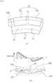
- a plurality of radial grooves 32R, 32L for generating dynamic pressure during rotationis provided in the circumferential direction of a sealing face 31 of a mating ring 30 constituting one of a pair of sliding parts, with a dynamic pressure-generating groove 32 comprising tapering surfaces 33R, 33L tapering in opposite directions being formed following the circumferential direction so that the boundary between one pair of radial grooves 32R, 32L is in a trough formed by the tapering surfaces, and a dam 34 being formed at the boundary so as to separate the radial grooves 32R, 32L.
- the dynamic pressure-generating groove 32 of the prior arthas a shape for creating a dynamic pressure effect, and does not have an element for controlling seal integrity.
- the generation of the dynamic pressurecauses the fluid film to thicken, and the sealing faces of the mating ring and the seal ring break contact, so that, while sliding resistance decreases, leakage increases.
- JP 2009-14183refers to a sliding face structure.
- the sliding face structurecomprises a sliding face 1a of a first member 1 and a sliding face 2a of a second member 2, which relatively slide under the existence of lubricant.
- the direction of a periodical structure of grating portions 3a, 3b neighboring each other along the sliding directionis symmetrical to the sliding direction.
- US 5,447,316is directed to a gas seal, which includes a pair of relatively rotatable slide members and a plurality of grooves for generating a hydrodynamic floating force between sliding surfaces of the slide members during rotation.
- the plurality of groovesare circumferentially formed to one of the slide members so as to extend in a radial direction.
- a first dam portion for partitioning an inside space in the grooves from an external portion on an outer diameter side of the groovesis formed along an entire peripheral portion of the one of the slide members.
- Each of the grooveshas a V-shaped cross section having a central bottom portion and tapered portions extending from the central bottom portion with inclinations reverse to each other in the circumferential direction thereof and a second dam portion is formed to the bottom portion so as to extend upward.
- US 2002/0109302 A1is directed to a shaft seal device comprising: a casing having a hollow portion, a rotatable shaft extending inside the casing from a sealed fluid region to an outer region, a non-contact type first mechanical seal arranged between the casing and the shaft so as to divide the hollow portion into the sealed fluid region and a purge region located between the sealed fluid region and the outer region, and a second mechanical seal arranged between the casing and the shaft so as to divide the hollow portion into the purge region and the outer region, wherein the first mechanical seal comprises a first rotating seal ring having a first rotating seal surface rotating along with the shaft and a first non-rotating seal ring held by the casing and having a first non-rotating seal surface able to abut axially and slidable against the first rotating seal surface, a plurality of first hydrodynamic grooves communicating with the purge region formed at the first seal surface or the first non-rotating seal surface so as to extend from an inner circumferential edge thereof to an outer circum
- the present inventionwas contrived in order to resolve the problems in the prior art, it being an object thereof to provide sliding parts that do not leak when stopped, operate under fluid lubrication and prevent leakage when rotating, including during initial rotation, and are capable of striking a balance between seal tightness and lubrication.
- a first aspect of the sliding parts according to the present inventionconsists in sliding parts in accordance with the appended claim 1, sliding parts for allowing opposing sealing faces of an annular stationary ring fixed on a fixed side and an annular rotating ring that rotates along with a rotating shaft to rotate relative to each another, thereby sealing a sealed fluid present on one side in the radial direction of the relatively rotational sealing faces; the sliding parts being characterized in:
- leakageis prevented when the sliding parts are stopped, and the pumping action of the pumping areas during periods of low speed when rotation commences allows for sufficient lubrication, enabling sliding resistance to be reduced and stable sliding properties to be obtained.
- the dynamic pressure-generation action of the dynamic pressure-generating grooves during rotationensures that a sufficient lubricant film is formed by the sealed fluid between the sealing faces, allowing for improved sliding properties. Leakage of the sealed fluid from the sealing faces when dynamic pressure is being generated can be controlled by the pumping action of the pumping areas, allowing for seal integrity to be controlled.
- sliding parts according to the first aspectare characterized in the pumping areas being provided with intake pumping areas operating in a direction taking in the sealed fluid and outflow pumping areas operating in a direction in which the sealed fluid is expelled.
- a sealed fluid flow from the sealed fluid side between the sealing faces back to the sealed fluid sideis formed, thereby preventing excessive leakage during rotation, and improving seal properties.
- the sliding partsare characterized in the pumping areas having periodic linear indentation structures, and the linear indentations being formed so that the direction of the indentations is inclined at a predetermined angle with respect to the sliding direction of the sealing faces.
- the pumping areascan be formed using periodic linear indentation structures, enabling easy pumping formation, and allowing for pumping performance to be modified by modifying the angle of inclination.
- sliding parts according to the first or second aspectare characterized in the periodic linear indentation structures of the plurality of pumping areas being formed so that the directions of the linear indentations of adjacent pumping areas are symmetrical with respect to the sliding direction of the sealing faces.
- the present aspectallows for application in cases in which the sealing faces rotate in two directions.
- sliding parts according to any of the first through the third aspectsare characterized in the periodic linear indentation structures of the pumping areas being formed via irradiation with a femtosecond laser.
- both the directionality and machining position of the periodic linear indentation structure of the pumping areascan be controlled, enabling desired periodic linear indentation structures to be formed within each of discontinuous small divisions.
- seal integrity controlcan be optimized, allowing for maximum improvement of seal properties.
- the sliding partsare characterized in the radial grooves making up the plurality of dynamic pressure-generating groove groups having tapered shapes tapering in opposite directions with respect to the circumferential direction so as to increase in height as they approach a boundary therebetween, and dam parts separating the radial grooves being provided at the boundary therebetween, one pair of adjacent radial grooves being taken as a single group.
- the buoyancy working upon the sealing facescan be increased, allowing dynamic pressure-generating means optimally suited to mechanical seals of both high-pressure and high-speed rotation types to be achieved.
- sliding parts according to any of the first through the fifth aspectsare characterized in the dynamic pressure-generating grooves extending roughly in the radial direction of the sealing face from an outer circumferential end towards an inner circumference side thereof, and bending in the inner circumferential side to form roughly L-shaped grooves extending roughly in the circumferential direction.
- the sealed fluidis readily drawn into the grooves, and, once drawn in, the sealed fluid is not readily expelled, allowing for strong buoyancy to be generated.
- sliding parts according to any of the first through the sixth aspectsare characterized in the tapered shape of the bottom surfaces with respect to the circumferential direction within the radial grooves of the dynamic pressure-generating grooves being stepped, rectilinear, or curvilinear, and the depth of the linear indentations of the pumping areas being set so as to vary according to the depth of the radial grooves.
- pumping actioncan be generated according to the amount of sealed fluid drawn into the dynamic pressure-generating groove.
- the present inventionyields the following superior effects.
- Fig. 1is a front cross-sectional view of an example of a mechanical seal for general industrial machinery.
- the mechanical seal shown in Fig. 1is an inside-type seal for sealing a sealed fluid attempting to leak from the outer circumference of a sealing face in the inner circumference direction, in which an annular rotating ring 3 rotatably provided integrally with a rotating shaft 1 for driving a sealed fluid-side pump impeller (not shown), a sleeve 2 being interposed between the rotating shaft 1 and the rotating ring 3, and an annular stationary ring 6 non-rotatably but movably provided with respect to an axial direction on a seal cover 5 fixed to a pump housing 4 are configured so that sealing faces S imparted with a mirrored finish via lapping or another process slide in close contact thanks to a bellows 7 urging the stationary ring 6 in the axial direction.
- this mechanical sealthe sealed fluid is prevented from escaping from the outer circumference of the rotating shaft 1 out to the atmosphere side at the sealing faces S of the rotating ring 3 and the stationary ring 6.
- the rotating ring 3 and stationary ring 6are typically both formed from SiC (a hard material), or from a combination of SiC (a hard material) and carbon (a soft material), but a sliding material used in mechanical seals can be applied as the sliding material.
- the SiCcan be a sintered piece in which boron, aluminum, carbon, or the like is used as a sintering aid, or another material having two or more types of phases of differing components or composition, such as SiC containing dispersed graphite particles, reaction-sintered SiC of SiC and Si, SiC-TiC, SiC-TiN, and the like.
- the carboncan be carbon containing a mixture of carbon and graphite, or resin-molded carbon, sintered carbon, or the like.
- a metal material, resin material, surface-modified material (coating material), composite material, or the likecan also be used.
- Fig. 2is a front cross-sectional view of an example of a mechanical seal for a water pump.
- the mechanical seal shown in Fig. 2is an inside-type seal for sealing cooling water attempting to leak from the outer circumference of a sealing face in the inner circumference direction, in which an annular rotating ring 3 rotatably provided integrally with a rotating shaft 1 for driving a cooling water-side pump impeller (not shown), a sleeve 2 being interposed between the rotating shaft 1 and the rotating ring 3, and an annular stationary ring 6 non-rotatably but movably provided with respect to the axial direction on a pump housing 4 are configured so that sealing faces S imparted with a mirrored finish via lapping or another process slide in close contact thanks to a coiled wave spring 8 and a bellows 9 urging the stationary ring 6 in the axial direction.
- this mechanical sealthe cooling water is prevented from flowing from the outer circumference of the rotating shaft 1 out to the atmosphere side at the sealing faces S of the rotating ring 3 and the stationary ring 6.
- FIG. 3is an illustration of dynamic pressure-generating grooves and pumping areas formed in a sealing face of a rotating ring according to a first embodiment of the present invention, with FIG. 3(a) being a plan view thereof and FIG. 3(b) being a cross-sectional view along line X-X in FIG. 3(a) .
- the rotating ring 3is referred to as a mating ring, and is often formed from SiC (a hard material).
- a plurality of dynamic pressure-generating grooves 20is discontinuously formed in the circumferential direction of the sealing face S of the rotating ring 3.
- the dynamic pressure-generating grooves 20are formed so that, taking one pair of adjacent radial grooves 20a, 20b as a single group, the radial grooves making up the plurality of dynamic pressure-generating groove groups have tapered shapes tapering in opposite directions with respect to the circumferential direction so as to increase in height as they approach a boundary therebetween, and dam parts 21 separating the radial grooves are provided at the boundaries therebetween.
- the number of dynamic pressure-generating grooves 20 provided on the sealing face Smay be as desired, and an optimal number may be calculated according to design.
- the dynamic pressure-generating grooves 20 shown in FIG. 3(a)extend roughly in the radial direction of the sealing face S of the rotating ring 3 from an outer circumferential end towards the inner circumference thereof, and bend in the inner circumferential side to form roughly L-shaped grooves extending roughly in the circumferential direction.
- the dynamic pressure-generating grooves 20communicate with the sealed fluid side at the outer circumference of the rotating ring 3, and are configured so as to readily draw the sealed fluid into the grooves.
- the depth of the dynamic pressure-generating grooves 20gradually varies along the sliding direction in the parts thereof extending in the circumferential direction. Specifically, the depth of the dynamic pressure-generating grooves 20 increases in steps in the direction indicated by arrow r1 in the radial direction groove 20a, and increases in steps in the direction indicated by arrow r2 in the radial direction groove 20b. In other words, the radial grooves 20a and 20b of the dynamic pressure-generating groove 20 increase in height as they approach the boundary therebetween.
- the spaces between the dynamic pressure-generating grooves 20 and the opposed sealing face of the stationary ring 6first grow narrower proceeding inward with respect to the radial direction, then, while widening again in the parts bent in the circumferential direction, grow shallower proceeding in the circumferential direction, so that the sealed fluid is ultimately compressed.
- the gradual compression of the sealed fluidgenerates dynamic pressure that works to force the rotating ring 3 and the stationary ring 6 apart.
- a lubricant filmis thus more readily formed by the sealed fluid between the rotating ring 3 and the sealing face S of the stationary ring 6, improving sliding properties.
- the dynamic pressure-generating groovehas a rough letter-L shape in the dynamic pressure-generating groove 20 according to the present embodiment, the sealed fluid drawn into radial direction groove 20b is readily expelled, allowing leakage to be prevented.
- the dynamic pressure-generating grooves 20can be formed in the sealing face S, which is machined to a mirror finish, via fine machining using a YVO 4 laser or sandblasting.
- the groovesmay also be formed by cutting, depending on the size of the product.
- the dynamic pressure-generating grooves 20are formed to a maximum depth of 0.1-5 ⁇ m.
- Pumping areas 10are formed within the dynamic pressure-generating grooves 20.
- pumping areas 10are formed over the entire surface of the floor of the dynamic pressure-generating grooves 20, but the pumping areas 10 need not necessarily be formed over the entire surface; it is acceptable for them to be formed on only a part thereof.
- pumping areas 10 for generating pumping action via the relative rotational sliding of the stationary ring 6 and the rotating ring 3are formed within the dynamic pressure-generating grooves 20, as described above.
- the pumping areas 10are provided with intake pumping areas 10a operating in a direction in which the sealed fluid is drawn in and outflow pumping areas 10b operating in a direction in which the sealed fluid is expelled.
- a plurality of parallel linear indentations(also referred to as a "periodic linear indentation structure" in the present invention) is formed at a constant pitch in each of the pumping areas 10, the periodic linear indentation structure being a fine structure formed using, for example, a femtosecond laser.
- linear indentationsencompass not only rectilinear indentations, but also somewhat curved indentations appearing during the process of forming rectilinear indentations, as well as curvilinear indentations.
- the linear indentations formed in the pumping areas 10incline at a predetermined angle ⁇ with respect to the sliding direction of the sealing faces S; i.e., with the direction of the tangent line of the rotation of the sealing faces S.
- the predetermined angle ⁇is preferably 10° to 80° with respect to the tangent of the rotation of the sealing face S in both the inner circumference direction and the outer circumference direction of the sealing face S.
- the angle of inclination ⁇ with respect to the tangent of rotation of the linear indentations of the pumping areas 10 in each of the plurality of pumping areas 10may be the same for all pumping areas 10, or may differ for each of the pumping areas 10. However, because the sliding properties of the sealing faces S are affected by the angle of inclination ⁇ , imparting the linear indentations of all of the pumping areas 10 with an appropriate specific angle of inclination ⁇ according to the desired lubricity and sliding conditions is effective in order to obtain stable sliding properties.
- the radial grooves 20a, 20bare configured so that the angle of inclination ⁇ with respect to the tangent of rotation is constant for each step.
- the angle of inclination ⁇ of the linear indentations of the plurality of pumping areas 10 with respect to the tangent of rotationwill be defined as a specific optimal angle.
- the angle of inclination ⁇ of the linear indentations of the intake pumping areas 10a and outflow pumping areas 10bare preferably formed so as to be symmetrical with respect to the tangent of rotation.
- the intake pumping areas 10a and outflow pumping areas 10bare preferably formed so as to be alternatingly disposed along the circumferential direction of the sealing faces S.
- the sealing faces S shown in Fig. 3have a preferable configuration for cases in which the sealing faces S rotate in both directions.
- the intake pumping areas 10a and outflow pumping areas 10bneed not be alternatingly disposed along the sealing faces S in the circumferential direction, but rather, for example, two intake pumping areas 10a may be disposed for every outflow pumping area 10b; or the reverse ratio is also acceptable.
- the pumping areas 10, which are structures (periodic structures of linear indentations) in which a plurality of parallel linear indentations are disposed with high precision,are strictly divided, for example, by using a femtosecond laser within a predetermined area of the sealing face S, then precisely controlling the laser and forming in the direction of the linear indentations in each division.
- the interference of the incident light and scattered light or plasma waves along the surface of the substratewill lead to an periodic structure of linear indentations having a wavelength-order pitch and groove depth self-forming orthogonally to the polarization direction.
- the femtosecond lasermay be overlappingly operated, thereby allowing a periodic linear indentation structure pattern to be formed on the surface.
- a periodic linear indentation structure formed using a femtosecond laserin this way, the directionality thereof can be controlled, as well as the machining position, allowing a desired periodic linear indentation structure to be formed within each of disparate small divisions.
- a fine periodic patterncan be selectively formed on the sealing face.
- using a machining method involving a femtosecond laserallows for the formation of a periodic structure of linear indentations of sub-micron order depth, which are effective in improving the lubrication and reducing the leakage of the mechanical seal.
- the pumping areas 10are not limited to being formed using a femtosecond laser; a picosecond laser or electron beam may also be used.
- the pumping areas 10may also be formed by performing stamping or imprinting using a die provided with a periodic linear indentation structure while the sealing face of the annular mechanical seal sliding member is being rotated.
- the sealed fluid side of the sealing face in which the dynamic pressure-generating grooves 20 and pumping areas 10 are formed and the opposing inner circumference sidemust function as a seal dam for preventing leakage when stopped. Because a seal dam area 11 for yielding this seal dam function is not fully covered by the sealed fluid (lubricating fluid), it is liable to be poorly lubricated and exhibit wear. In order to prevent wear of the seal dam area 11 and reduce sliding friction, the seal dam area 11 is preferably formed from a sliding material of superior lubricity.
- the depth h of the dynamic pressure-generating grooves 20is preferably within the range 1 ⁇ m ⁇ h ⁇ 100 ⁇ m, and the depth d from the apexes to the troughs of the linear indentations of the pumping areas 10 is preferably within the range 0.1 ⁇ m ⁇ d ⁇ 10 ⁇ m.
- the pitch p of the linear indentations of the pumping areas 10is preferably within the range 0.1 ⁇ m ⁇ p ⁇ 10 ⁇ m.
- the tapered shape tapering with respect to the circumferential direction of the bottom surface of the radial grooves in the dynamic pressure-generating grooves 20is a stepped shape, as shown in Fig. 3 , the depth h of the dynamic pressure-generating grooves 20 varies in stages, so that the depth d between the apexes and the troughs of the indentations within the pumping areas 10 also varies accordingly. It is thereby possible to generate pumping action according to the amount of sealed fluid drawn into the dynamic pressure-generating grooves 20.
- the sealed fluidis drawn into the radial direction groove 20a on the right
- the intake pumping areas 10a formed within the radial direction groove 20aalso act to draw in the sealed fluid
- the sealed fluidis expelled from the radial direction groove 20b on the left
- the outflow pumping areas 10b formed within the radial direction groove 20bact to expel the sealed fluid to the sealed fluid side.
- the radial grooves and the pumping areasact to draw in and expel the sealed fluid
- the amount of sealed fluid over the sealing faces Sincreases, and, simultaneously, a flow is formed such that the sealed fluid is drawn in from the sealed fluid side and expelled back to the sealed fluid side.
- a sufficient lubricant filmis thereby formed by the sealed fluid between the sealing faces S, improving sliding properties, reducing sealed fluid leakage, and allowing for improved seal properties.
- FIG. 4is an illustration of dynamic pressure-generating grooves and pumping area formed in a sealing face of a rotating ring according to a second embodiment of the present invention, with FIG. 4(a) being a plan view thereof and FIG. 4(b) being a cross-sectional view along line Y-Y in FIG. 4(a) .
- the dynamic pressure-generating grooves 20 shown in FIG. 4(a)extend roughly in the radial direction of the sealing face S of the rotating ring 3 from an outer circumferential end towards the inner circumference thereof, and bend in the inner circumferential side to form roughly L-shaped grooves extending roughly in the circumferential direction.
- the dynamic pressure-generating grooves 20communicate with the sealed fluid side at the outer circumference of the rotating ring 3, and are configured so as to readily draw the sealed fluid into the grooves.
- the depth of the dynamic pressure-generating grooves 20gradually varies along the sliding direction in the parts thereof extending in the circumferential direction. Specifically, the depth of the dynamic pressure-generating grooves 20 linearly increases in the direction indicated by arrow r1 in the radial direction groove 20a, and linearly increases in the direction indicated by arrow r2 in the radial direction groove 20b.
- the depth d between the apexes and troughs of the indentations of the pumping areas 10preferably also varies continuously in proportion therewith, but a stepped shape is also possible to facilitate machining.
- the bottom surfaces of the radial grooves of the dynamic pressure-generating grooves 20are not limited to varying rectilinearly; they may comprise a combination of a plurality of surfaces inclining at different angles, or the bottom surfaces of the grooves may be curved to yield a curvilinear shape. In all of the above cases, the radial grooves are formed so as to increase in height towards the boundary therebetween.
- dynamic pressureis formed on the sealing faces S by the dynamic pressure-generating grooves 20 during rotation, and a lubricant film is formed by the sealed fluid between the sealing faces S of the rotating ring 3 and the stationary ring 6, improving sliding properties.
- leakage of the sealed fluid from the sealing faces when dynamic pressure is being generatedcan be controlled by the pumping action of the pumping areas, allowing for seal integrity to be controlled.
- a flowis generated whereby the sealed fluid is drawn into the intake pumping areas 10a, sent over the sealing face S to the outflow pumping areas 10b located at a separate position with respect to the circumferential direction, and returned to the sealed fluid side through the action of the outflow pumping areas 10b.
- This sealed fluid flowallows the lubrication of the sealing faces S during rotation to be ensured, leakage to be prevented, and seal integrity to be preserved.
- the sealed fluidis drawn into the radial direction groove 20a on the right
- the intake pumping areas 10a formed within the radial direction groove 20aalso act to draw in the sealed fluid
- the sealed fluidis expelled from the radial direction groove 20b on the left
- the outflow pumping areas 10b formed within the radial direction groove 20bact to expel the sealed fluid to the sealed fluid side.
- the radial grooves and the pumping areasact to draw in and expel the sealed fluid
- the amount of sealed fluid over the sealing faces Sincreases, and, simultaneously, a flow is formed such that the sealed fluid is drawn in from the sealed fluid side and expelled back to the sealed fluid side.
- a sufficient lubricant filmis thereby formed by the sealed fluid between the sealing faces S, improving sliding properties, reducing sealed fluid leakage, and allowing for improved seal properties.
- the dynamic pressure-generating grooves 20 and the pumping areas 10are formed on the sealing face of the rotating ring 3, but the reverse configuration, in which the dynamic pressure-generating grooves 20 and the pumping areas 10 are formed on the sealing face of the stationary ring 6, is also possible.
- the dynamic pressure-generating grooves 20 and the pumping areas 10may optionally be inclined with respect to the radial direction as necessary.
- the radial direction groove 20a and the intake pumping areas 10a of the dynamic pressure-generating groove 20may be formed so as to gradually decrease in height towards the interior with respect to the radial direction, allowing the sealed fluid to be drawn in more easily
- the radial direction groove 20b and the outflow pumping areas 10b of the dynamic pressure-generating groove 20to be formed so as to gradually increase in height towards the interior with respect to the radial direction, allowing the sealed fluid to be expelled more easily.
- the dynamic pressure-generating grooves 20 and the pumping areas 10are formed facing the inner circumference side.
Landscapes
- Engineering & Computer Science (AREA)
- General Engineering & Computer Science (AREA)
- Mechanical Engineering (AREA)
- Physics & Mathematics (AREA)
- Fluid Mechanics (AREA)
- Mechanical Sealing (AREA)
Description
- The present invention relates to relatively rotating sliding parts, and in particular to sliding parts used, for example, in the field of automotive seals, general industrial mechanical seals, and other types of mechanical seals.
- In sealing apparatus for preventing the leakage of a sealed fluid, such apparatus comprising two parts configured so as to rotate relatively to one another and so that end surfaces thereof slide along a plane, such as, for example, a mechanical seal, a balance must be struck between the two opposing conditions of seal tightness and lubrication in order to maintain seal integrity for extended periods of time. In recent years, environmental concerns in particular have led to an increase in demand for reduced friction in order to reduce mechanical damage while preventing sealed fluid leakage. Methods of reducing friction include the so-called fluid lubrication state, in which dynamic pressure is generated between sealing faces due to rotation, and the surfaces slide with a liquid film interposed therebetween. However, in such cases, positive pressure is generated between the sealing faces, so that the fluid escapes from the positive pressure portion outside of the sealing faces. Such fluid outflow constitutes leakage in the case of a seal.
- Mechanical seals such as that shown in
Fig. 5 , in which dynamic pressure is generated between sealing faces via rotation, are known in the art ("prior art"; see, for example, patent document 1). In the prior art shown inFig. 5 , a plurality ofradial grooves face 31 of amating ring 30 constituting one of a pair of sliding parts, with a dynamic pressure-generatinggroove 32 comprising taperingsurfaces radial grooves dam 34 being formed at the boundary so as to separate theradial grooves - As shown in
Fig. 5(b) , when the sliding parts rotate relative to each another, the pressure in theradial direction groove 32R, which lies in the upstream direction of a sealed fluid flow G, decreases, creating negative buoyancy, and the wedge effect of the taperingsurface 33L in theradial direction groove 32L on the downstream side of thedam 34 increases pressure, creating positive buoyancy. At this time, the action of thedam 34 decreases the negative pressure and increases the positive pressure, creating a net positive pressure and allowing a strong buoyancy to be obtained. - However, the dynamic pressure-generating
groove 32 of the prior art has a shape for creating a dynamic pressure effect, and does not have an element for controlling seal integrity. Thus, there is the problem that, while dynamic pressure is generated by the dynamic pressure-generatinggroove 32 when the mating ring and a seal ring constituting the sliding parts rotate relative to each other, the generation of the dynamic pressure causes the fluid film to thicken, and the sealing faces of the mating ring and the seal ring break contact, so that, while sliding resistance decreases, leakage increases. - In addition, the dynamic pressure yielded by the dynamic pressure-generating
groove 32 according to the prior art is not generated unless the rotating shaft reaches a certain degree of rotational speed. There is also the problem that, for this reason, sufficient quantities of sealed fluid cannot be introduced between the sealing faces during the period from when rotation begins until dynamic pressure is generated, leading to reduced lubrication and increased torque, in turn leading to the problems of seizing, vibration, noise, and the like being generated and sliding properties becoming unstable. - Examples of prior art in which dynamic pressure-generating grooves are provided in order to prevent wear during sliding part rotation are known (for example, see patent document 2), but, because these examples lack an element for controlling seal integrity, like the prior art described above, they have the problem of increased leakage.
JP 2009-14183 first member 1 and a sliding face 2a of asecond member 2, which relatively slide under the existence of lubricant. On the sliding face 1a of at least one of thefirst member 1 and thesecond member 2, a plurality of gratingportions 3 consisting of a plurality of irregular faces are formed along the sliding direction. The direction of a periodical structure of grating portions 3a, 3b neighboring each other along the sliding direction is symmetrical to the sliding direction.US 5,447,316 is directed to a gas seal, which includes a pair of relatively rotatable slide members and a plurality of grooves for generating a hydrodynamic floating force between sliding surfaces of the slide members during rotation. The plurality of grooves are circumferentially formed to one of the slide members so as to extend in a radial direction. A first dam portion for partitioning an inside space in the grooves from an external portion on an outer diameter side of the grooves is formed along an entire peripheral portion of the one of the slide members. Each of the grooves has a V-shaped cross section having a central bottom portion and tapered portions extending from the central bottom portion with inclinations reverse to each other in the circumferential direction thereof and a second dam portion is formed to the bottom portion so as to extend upward.US 2002/0109302 A1 is directed to a shaft seal device comprising: a casing having a hollow portion, a rotatable shaft extending inside the casing from a sealed fluid region to an outer region, a non-contact type first mechanical seal arranged between the casing and the shaft so as to divide the hollow portion into the sealed fluid region and a purge region located between the sealed fluid region and the outer region, and a second mechanical seal arranged between the casing and the shaft so as to divide the hollow portion into the purge region and the outer region, wherein the first mechanical seal comprises a first rotating seal ring having a first rotating seal surface rotating along with the shaft and a first non-rotating seal ring held by the casing and having a first non-rotating seal surface able to abut axially and slidable against the first rotating seal surface, a plurality of first hydrodynamic grooves communicating with the purge region formed at the first seal surface or the first non-rotating seal surface so as to extend from an inner circumferential edge thereof to an outer circumferential edge direction, and a purge fluid higher in pressure than the pressure of the sealed fluid fed into the purge region.- Patent Document 1: Japanese Laid-Open Patent Publication
H4-73 - Patent Document 2: Japanese Laid-Open Patent Publication
2006-22834 - Patent Document 3: Japanese Laid-Open Patent Publication
2009-14183 - Patent Document 4: United States Patent
5,477,316 - Patent Document 5: United States Patent Application
US 2002/0109302 A1 . - The present invention was contrived in order to resolve the problems in the prior art, it being an object thereof to provide sliding parts that do not leak when stopped, operate under fluid lubrication and prevent leakage when rotating, including during initial rotation, and are capable of striking a balance between seal tightness and lubrication.
- In order to achieve the above object, a first aspect of the sliding parts according to the present invention consists in sliding parts in accordance with the appended
claim 1, sliding parts for allowing opposing sealing faces of an annular stationary ring fixed on a fixed side and an annular rotating ring that rotates along with a rotating shaft to rotate relative to each another, thereby sealing a sealed fluid present on one side in the radial direction of the relatively rotational sealing faces; the sliding parts being characterized in: - a plurality of dynamic pressure-generating grooves for generating dynamic pressure via the relative rotational sliding of the stationary ring and the rotating ring being formed in the circumferential direction on the sealing face of one of the stationary ring and the rotating ring so as to communicate with the sealed fluid-containing space; and
- pumping areas for generating pumping action via the relative rotational sliding of the stationary ring and the rotating ring being formed within the dynamic pressure-generating grooves.
- In accordance with the present aspect, leakage is prevented when the sliding parts are stopped, and the pumping action of the pumping areas during periods of low speed when rotation commences allows for sufficient lubrication, enabling sliding resistance to be reduced and stable sliding properties to be obtained. In addition, the dynamic pressure-generation action of the dynamic pressure-generating grooves during rotation ensures that a sufficient lubricant film is formed by the sealed fluid between the sealing faces, allowing for improved sliding properties. Leakage of the sealed fluid from the sealing faces when dynamic pressure is being generated can be controlled by the pumping action of the pumping areas, allowing for seal integrity to be controlled.
- Secondly, sliding parts according to the first aspect are characterized in the pumping areas being provided with intake pumping areas operating in a direction taking in the sealed fluid and outflow pumping areas operating in a direction in which the sealed fluid is expelled.
- In accordance with the present aspect, a sealed fluid flow from the sealed fluid side between the sealing faces back to the sealed fluid side is formed, thereby preventing excessive leakage during rotation, and improving seal properties.
- Still according to the first aspect, the sliding parts are characterized in the pumping areas having periodic linear indentation structures, and the linear indentations being formed so that the direction of the indentations is inclined at a predetermined angle with respect to the sliding direction of the sealing faces.
- In accordance with the present aspect, the pumping areas can be formed using periodic linear indentation structures, enabling easy pumping formation, and allowing for pumping performance to be modified by modifying the angle of inclination.
- Thirdly, sliding parts according to the first or second aspect are characterized in the periodic linear indentation structures of the plurality of pumping areas being formed so that the directions of the linear indentations of adjacent pumping areas are symmetrical with respect to the sliding direction of the sealing faces.
- The present aspect allows for application in cases in which the sealing faces rotate in two directions.
- Fourthly, sliding parts according to any of the first through the third aspects are characterized in the periodic linear indentation structures of the pumping areas being formed via irradiation with a femtosecond laser.
- In accordance with the present aspect, both the directionality and machining position of the periodic linear indentation structure of the pumping areas can be controlled, enabling desired periodic linear indentation structures to be formed within each of discontinuous small divisions.
- Fifthly, sliding parts according to any of the first through the fourth aspects are characterized in the depthd of the linear indentations of the pumping areas being within a ranged = 0.1h-10h, and the pitchp of the indentations being within a rangep = 0.1h-10h,h being the depth of the dynamic pressure-generating grooves.
- In accordance with the present aspect, seal integrity control can be optimized, allowing for maximum improvement of seal properties.
- Still according to the first aspect, the sliding parts are characterized in the radial grooves making up the plurality of dynamic pressure-generating groove groups having tapered shapes tapering in opposite directions with respect to the circumferential direction so as to increase in height as they approach a boundary therebetween, and dam parts separating the radial grooves being provided at the boundary therebetween, one pair of adjacent radial grooves being taken as a single group.
- In accordance with the present aspect, the buoyancy working upon the sealing faces can be increased, allowing dynamic pressure-generating means optimally suited to mechanical seals of both high-pressure and high-speed rotation types to be achieved.
- Sixthly, sliding parts according to any of the first through the fifth aspects are characterized in the dynamic pressure-generating grooves extending roughly in the radial direction of the sealing face from an outer circumferential end towards an inner circumference side thereof, and bending in the inner circumferential side to form roughly L-shaped grooves extending roughly in the circumferential direction.
- In accordance with the present aspect, the sealed fluid is readily drawn into the grooves, and, once drawn in, the sealed fluid is not readily expelled, allowing for strong buoyancy to be generated.
- Seventhly, sliding parts according to any of the first through the sixth aspects are characterized in the tapered shape of the bottom surfaces with respect to the circumferential direction within the radial grooves of the dynamic pressure-generating grooves being stepped, rectilinear, or curvilinear, and the depth of the linear indentations of the pumping areas being set so as to vary according to the depth of the radial grooves.
- In accordance with the present aspect, pumping action can be generated according to the amount of sealed fluid drawn into the dynamic pressure-generating groove.
- The present invention yields the following superior effects.
- (1) In accordance with the first aspect, leakage is prevented when the sliding parts are stopped, and sufficient lubrication during periods of low speed when rotation commences is possible, enabling sliding resistance to be reduced and stable sliding properties to be obtained. In addition, a sufficient lubricant film is formed by the sealed fluid between the sealing faces, allowing for improved sliding properties. Moreover, leakage of the sealed fluid from the sealing faces when dynamic pressure is being generated can be controlled by the pumping action of the pumping areas, allowing for seal integrity to be controlled.
- (2) In accordance with the second aspect, a sealed fluid flow from the sealed fluid side between the sealing faces back to the sealed fluid side is formed, thereby preventing excessive leakage during rotation, and improving seal properties.
- (3) In accordance with the first aspect, pumping can be easily formed, and pumping performance can be modified by modifying the angle of inclination.
- (4) The third aspect allows for application in cases in which the sealing faces rotate in two directions.
- (5) In the fourth aspect, both the directionality and machining position of the periodic linear indentation structure of the pumping areas can be controlled, enabling a desired periodic linear indentation structure to be formed within each of discontinuous small divisions.
- (6) In accordance with the fifth aspect, seal integrity control can be optimized, allowing for maximum improvement of seal properties.
- (7) In accordance with the first aspect, the buoyancy working upon the sealing faces can be increased, allowing dynamic pressure-generating means optimally suited to mechanical seals of both high-pressure and high-speed rotation types to be achieved.
- (8) In accordance with the sixth aspect, the sealed fluid is readily drawn into the grooves, and, once drawn in, the sealed fluid is not readily expelled, allowing for strong buoyancy to be generated.
- (9) In accordance with the seventh aspect, pumping action can be generated according to the amount of sealed fluid drawn into the dynamic pressure-generating groove.
Fig. 1 is a front cross-sectional view of an example of a mechanical seal for general industrial machinery;Fig. 2 is a front cross-sectional view of an example of a mechanical seal for a water pump;Fig. 3 is an illustration of dynamic pressure-generating grooves and pumping area formed in a sealing face of a rotating ring according to a first embodiment of the present invention, withFIG. 3(a) being a plan view thereof andFIG. 3(b) being a cross-sectional view along line X-X inFIG. 3(a) ;Fig. 4 is an illustration of dynamic pressure-generating grooves and pumping area formed in a sealing face of a rotating ring according to a second embodiment of the present invention, withFIG. 4(a) being a plan view thereof andFIG. 4(b) being a cross-sectional view along line Y-Y inFIG. 4(a) ; andFig. 5 is an illustration of the prior art.- An embodiment of the sliding parts according to the present invention will be described in detail with reference to the drawings.
- In the description of the present embodiment, an example in which parts constituting a mechanical seal are sliding parts is given, but the present invention should not be construed as being limited to such; various alterations, modifications, and improvements may be made according to the knowledge of a person skilled in the art within the scope of the present invention, the latter being defined by the appended claims.
Fig. 1 is a front cross-sectional view of an example of a mechanical seal for general industrial machinery.- The mechanical seal shown in
Fig. 1 is an inside-type seal for sealing a sealed fluid attempting to leak from the outer circumference of a sealing face in the inner circumference direction, in which an annularrotating ring 3 rotatably provided integrally with arotating shaft 1 for driving a sealed fluid-side pump impeller (not shown), asleeve 2 being interposed between therotating shaft 1 and therotating ring 3, and an annularstationary ring 6 non-rotatably but movably provided with respect to an axial direction on aseal cover 5 fixed to apump housing 4 are configured so that sealing faces S imparted with a mirrored finish via lapping or another process slide in close contact thanks to abellows 7 urging thestationary ring 6 in the axial direction. In other words, in this mechanical seal, the sealed fluid is prevented from escaping from the outer circumference of therotating shaft 1 out to the atmosphere side at the sealing faces S of therotating ring 3 and thestationary ring 6. - The
rotating ring 3 andstationary ring 6 are typically both formed from SiC (a hard material), or from a combination of SiC (a hard material) and carbon (a soft material), but a sliding material used in mechanical seals can be applied as the sliding material. The SiC can be a sintered piece in which boron, aluminum, carbon, or the like is used as a sintering aid, or another material having two or more types of phases of differing components or composition, such as SiC containing dispersed graphite particles, reaction-sintered SiC of SiC and Si, SiC-TiC, SiC-TiN, and the like. The carbon can be carbon containing a mixture of carbon and graphite, or resin-molded carbon, sintered carbon, or the like. Apart from the abovementioned sliding materials, a metal material, resin material, surface-modified material (coating material), composite material, or the like can also be used. Fig. 2 is a front cross-sectional view of an example of a mechanical seal for a water pump.- The mechanical seal shown in
Fig. 2 is an inside-type seal for sealing cooling water attempting to leak from the outer circumference of a sealing face in the inner circumference direction, in which an annularrotating ring 3 rotatably provided integrally with arotating shaft 1 for driving a cooling water-side pump impeller (not shown), asleeve 2 being interposed between therotating shaft 1 and therotating ring 3, and an annularstationary ring 6 non-rotatably but movably provided with respect to the axial direction on apump housing 4 are configured so that sealing faces S imparted with a mirrored finish via lapping or another process slide in close contact thanks to a coiledwave spring 8 and a bellows 9 urging thestationary ring 6 in the axial direction. In other words, in this mechanical seal, the cooling water is prevented from flowing from the outer circumference of therotating shaft 1 out to the atmosphere side at the sealing faces S of therotating ring 3 and thestationary ring 6. Fig. 3 is an illustration of dynamic pressure-generating grooves and pumping areas formed in a sealing face of a rotating ring according to a first embodiment of the present invention, withFIG. 3(a) being a plan view thereof andFIG. 3(b) being a cross-sectional view along line X-X inFIG. 3(a) .- In
Fig. 3 , therotating ring 3 is referred to as a mating ring, and is often formed from SiC (a hard material). A plurality of dynamic pressure-generatinggrooves 20 is discontinuously formed in the circumferential direction of the sealing face S of therotating ring 3. The dynamic pressure-generatinggrooves 20 are formed so that, taking one pair of adjacentradial grooves dam parts 21 separating the radial grooves are provided at the boundaries therebetween. The number of dynamic pressure-generatinggrooves 20 provided on the sealing face S may be as desired, and an optimal number may be calculated according to design. - The dynamic pressure-generating
grooves 20 shown inFIG. 3(a) extend roughly in the radial direction of the sealing face S of therotating ring 3 from an outer circumferential end towards the inner circumference thereof, and bend in the inner circumferential side to form roughly L-shaped grooves extending roughly in the circumferential direction. The dynamic pressure-generatinggrooves 20 communicate with the sealed fluid side at the outer circumference of therotating ring 3, and are configured so as to readily draw the sealed fluid into the grooves. - As shown in
Fig. 3(b) , the depth of the dynamic pressure-generatinggrooves 20 gradually varies along the sliding direction in the parts thereof extending in the circumferential direction. Specifically, the depth of the dynamic pressure-generatinggrooves 20 increases in steps in the direction indicated by arrow r1 in theradial direction groove 20a, and increases in steps in the direction indicated by arrow r2 in theradial direction groove 20b. In other words, theradial grooves groove 20 increase in height as they approach the boundary therebetween. - Following the path taken by the sealed fluid as it is drawn from the sealed fluid into the grooves, the spaces between the dynamic pressure-generating
grooves 20 and the opposed sealing face of thestationary ring 6 first grow narrower proceeding inward with respect to the radial direction, then, while widening again in the parts bent in the circumferential direction, grow shallower proceeding in the circumferential direction, so that the sealed fluid is ultimately compressed. The gradual compression of the sealed fluid generates dynamic pressure that works to force therotating ring 3 and thestationary ring 6 apart. A lubricant film is thus more readily formed by the sealed fluid between therotating ring 3 and the sealing face S of thestationary ring 6, improving sliding properties. In particular, because the dynamic pressure-generating groove has a rough letter-L shape in the dynamic pressure-generatinggroove 20 according to the present embodiment, the sealed fluid drawn intoradial direction groove 20b is readily expelled, allowing leakage to be prevented. - The dynamic pressure-generating
grooves 20 can be formed in the sealing face S, which is machined to a mirror finish, via fine machining using a YVO4 laser or sandblasting. The grooves may also be formed by cutting, depending on the size of the product. - In the rotating ring according to the present embodiment, the dynamic pressure-generating
grooves 20 are formed to a maximum depth of 0.1-5 µm. - Pumping
areas 10 are formed within the dynamic pressure-generatinggrooves 20. InFig. 3 , pumpingareas 10 are formed over the entire surface of the floor of the dynamic pressure-generatinggrooves 20, but thepumping areas 10 need not necessarily be formed over the entire surface; it is acceptable for them to be formed on only a part thereof. - In order to reduce friction upon the mechanical seal, a liquid film roughly 0.1 µm to 10 µm thick is necessary, depending on the type, temperature, and the like of the sealed fluid. In order to obtain such a liquid film, pumping
areas 10 for generating pumping action via the relative rotational sliding of thestationary ring 6 and therotating ring 3 are formed within the dynamic pressure-generatinggrooves 20, as described above. Thepumping areas 10 are provided withintake pumping areas 10a operating in a direction in which the sealed fluid is drawn in andoutflow pumping areas 10b operating in a direction in which the sealed fluid is expelled. - In
Fig. 3 , when therotating ring 3 rotates in direction R, the sealed fluid is drawn into thepumping areas 10 and pushed back towards the sealed fluid side, as shown by the double-dotted dashed arrow. - A plurality of parallel linear indentations (also referred to as a "periodic linear indentation structure" in the present invention) is formed at a constant pitch in each of the
pumping areas 10, the periodic linear indentation structure being a fine structure formed using, for example, a femtosecond laser. - In the present invention, the "linear indentations" encompass not only rectilinear indentations, but also somewhat curved indentations appearing during the process of forming rectilinear indentations, as well as curvilinear indentations.
- In addition, as shown in
Fig. 3(a) , the linear indentations formed in thepumping areas 10 incline at a predetermined angleθ with respect to the sliding direction of the sealing faces S; i.e., with the direction of the tangent line of the rotation of the sealing faces S. The predetermined angleθ is preferably 10° to 80° with respect to the tangent of the rotation of the sealing face S in both the inner circumference direction and the outer circumference direction of the sealing face S. - The angle of inclinationθ with respect to the tangent of rotation of the linear indentations of the
pumping areas 10 in each of the plurality of pumpingareas 10 may be the same for all pumpingareas 10, or may differ for each of thepumping areas 10. However, because the sliding properties of the sealing faces S are affected by the angle of inclinationθ, imparting the linear indentations of all of thepumping areas 10 with an appropriate specific angle of inclinationθ according to the desired lubricity and sliding conditions is effective in order to obtain stable sliding properties. - In the case of
FIG. 3(a) , theradial grooves - Thus, if the sealing faces S rotatingly slide in a single direction, the angle of inclinationθ of the linear indentations of the plurality of pumping
areas 10 with respect to the tangent of rotation will be defined as a specific optimal angle. - When the sealing faces S rotatingly slide in both the forward and the reverse directions, the presence of both first pumping areas having linear indentations inclining at a first angle with respect to the tangent of rotation yielding suitable sliding properties during rotation in one direction and second pumping areas having linear indentations inclining at a second angle with respect to the tangent of rotation yielding suitable sliding properties during rotation in the opposite direction is preferable. Such a configuration allows suitable sliding properties to be obtained when the sealing faces S rotate in the forward and reverse directions.
- More specifically, if the sealing faces S rotate in both the forward and reverse directions, the angle of inclinationθ of the linear indentations of the
intake pumping areas 10a andoutflow pumping areas 10b are preferably formed so as to be symmetrical with respect to the tangent of rotation. - The
intake pumping areas 10a andoutflow pumping areas 10b are preferably formed so as to be alternatingly disposed along the circumferential direction of the sealing faces S. - The sealing faces S shown in
Fig. 3 have a preferable configuration for cases in which the sealing faces S rotate in both directions. - The
intake pumping areas 10a andoutflow pumping areas 10b need not be alternatingly disposed along the sealing faces S in the circumferential direction, but rather, for example, twointake pumping areas 10a may be disposed for everyoutflow pumping area 10b; or the reverse ratio is also acceptable. - The
pumping areas 10, which are structures (periodic structures of linear indentations) in which a plurality of parallel linear indentations are disposed with high precision, are strictly divided, for example, by using a femtosecond laser within a predetermined area of the sealing face S, then precisely controlling the laser and forming in the direction of the linear indentations in each division. - When a substrate is irradiated using a linearly polarized laser at an irradiation intensity near a machining threshold value, the interference of the incident light and scattered light or plasma waves along the surface of the substrate will lead to an periodic structure of linear indentations having a wavelength-order pitch and groove depth self-forming orthogonally to the polarization direction. Here, the femtosecond laser may be overlappingly operated, thereby allowing a periodic linear indentation structure pattern to be formed on the surface.
- In a periodic linear indentation structure formed using a femtosecond laser in this way, the directionality thereof can be controlled, as well as the machining position, allowing a desired periodic linear indentation structure to be formed within each of disparate small divisions. Specifically, if the sealing face of an annular mechanical seal sliding member is rotating while this method is used, a fine periodic pattern can be selectively formed on the sealing face. In addition, using a machining method involving a femtosecond laser allows for the formation of a periodic structure of linear indentations of sub-micron order depth, which are effective in improving the lubrication and reducing the leakage of the mechanical seal.
- The
pumping areas 10 are not limited to being formed using a femtosecond laser; a picosecond laser or electron beam may also be used. Thepumping areas 10 may also be formed by performing stamping or imprinting using a die provided with a periodic linear indentation structure while the sealing face of the annular mechanical seal sliding member is being rotated. - The sealed fluid side of the sealing face in which the dynamic pressure-generating
grooves 20 and pumpingareas 10 are formed and the opposing inner circumference side must function as a seal dam for preventing leakage when stopped. Because aseal dam area 11 for yielding this seal dam function is not fully covered by the sealed fluid (lubricating fluid), it is liable to be poorly lubricated and exhibit wear. In order to prevent wear of theseal dam area 11 and reduce sliding friction, theseal dam area 11 is preferably formed from a sliding material of superior lubricity. - The depthh of the dynamic pressure-generating
grooves 20 is preferably within therange 1 µm ≤h ≤ 100µm, and the depth d from the apexes to the troughs of the linear indentations of thepumping areas 10 is preferably within the range 0.1 µm ≤d ≤10 µm. The pitchp of the linear indentations of thepumping areas 10 is preferably within the range 0.1 µm ≤p ≤ 10 µm. - If the tapered shape tapering with respect to the circumferential direction of the bottom surface of the radial grooves in the dynamic pressure-generating
grooves 20 is a stepped shape, as shown inFig. 3 , the depthh of the dynamic pressure-generatinggrooves 20 varies in stages, so that the depthd between the apexes and the troughs of the indentations within thepumping areas 10 also varies accordingly. It is thereby possible to generate pumping action according to the amount of sealed fluid drawn into the dynamic pressure-generatinggrooves 20. - As described above, the formation of the
seal dam area 11, which is continuous with respect to the circumferential direction, prevents leakage when the sliding parts are stopped, and the sealed fluid is drawn into thepumping areas 10 and a lubricant film is formed on the sealing faces during period of low speed when rotation is beginning, thereby allowing for sufficient lubrication, and enabling sliding resistance to be reduced and stable sliding properties to be obtained. - In addition, dynamic pressure is formed on the sealing faces S by the dynamic pressure-generating
grooves 20 during rotation, and a lubricant film is formed by the sealed fluid between the sealing faces S of therotating ring 3 and thestationary ring 6, improving sliding properties. Moreover, leakage of the sealed fluid from the sealing faces when dynamic pressure is being generated can be controlled by the pumping action of the pumping areas, allowing for seal integrity to be controlled. At such time, a flow is generated whereby the sealed fluid is drawn into theintake pumping areas 10a, sent over the sealing face S to theoutflow pumping areas 10b located at a separate position with respect to the circumferential direction, and returned to the sealed fluid side through the action of theoutflow pumping areas 10b. The flow of the sealed fluid allows leakage during rotation to be reduced, and seal properties to be improved. - In particular, in
Fig. 3 , because thepumping areas 10 are formed within the dynamic pressure-generatinggrooves 20, the sealed fluid is drawn into theradial direction groove 20a on the right, theintake pumping areas 10a formed within theradial direction groove 20a also act to draw in the sealed fluid, the sealed fluid is expelled from theradial direction groove 20b on the left, and theoutflow pumping areas 10b formed within theradial direction groove 20b act to expel the sealed fluid to the sealed fluid side. As the radial grooves and the pumping areas act to draw in and expel the sealed fluid, the amount of sealed fluid over the sealing faces S increases, and, simultaneously, a flow is formed such that the sealed fluid is drawn in from the sealed fluid side and expelled back to the sealed fluid side. A sufficient lubricant film is thereby formed by the sealed fluid between the sealing faces S, improving sliding properties, reducing sealed fluid leakage, and allowing for improved seal properties. Fig. 4 is an illustration of dynamic pressure-generating grooves and pumping area formed in a sealing face of a rotating ring according to a second embodiment of the present invention, withFIG. 4(a) being a plan view thereof andFIG. 4(b) being a cross-sectional view along line Y-Y inFIG. 4(a) .- In
Fig. 4 , numbers identical to those inFig. 3 indicate identical parts ofFig. 3 ; redundant description of these will be omitted. - The dynamic pressure-generating
grooves 20 shown inFIG. 4(a) extend roughly in the radial direction of the sealing face S of therotating ring 3 from an outer circumferential end towards the inner circumference thereof, and bend in the inner circumferential side to form roughly L-shaped grooves extending roughly in the circumferential direction. The dynamic pressure-generatinggrooves 20 communicate with the sealed fluid side at the outer circumference of therotating ring 3, and are configured so as to readily draw the sealed fluid into the grooves. - As shown in
FIG. 4(b) , the depth of the dynamic pressure-generatinggrooves 20 gradually varies along the sliding direction in the parts thereof extending in the circumferential direction. Specifically, the depth of the dynamic pressure-generatinggrooves 20 linearly increases in the direction indicated by arrow r1 in theradial direction groove 20a, and linearly increases in the direction indicated by arrow r2 in theradial direction groove 20b. - Because the tapered shape in the circumferential direction of the radial grooves in the dynamic pressure-generating
grooves 20 varies rectilinearly, the depth d between the apexes and troughs of the indentations of thepumping areas 10 preferably also varies continuously in proportion therewith, but a stepped shape is also possible to facilitate machining. - The bottom surfaces of the radial grooves of the dynamic pressure-generating
grooves 20 are not limited to varying rectilinearly; they may comprise a combination of a plurality of surfaces inclining at different angles, or the bottom surfaces of the grooves may be curved to yield a curvilinear shape. In all of the above cases, the radial grooves are formed so as to increase in height towards the boundary therebetween. - In the second embodiment, as in the case of the first embodiment, the formation of the
seal dam area 11, which is continuous with respect to the circumferential direction, prevents leakage when the sliding parts are stopped, and the sealed fluid is drawn into thepumping areas 10 and a lubricant film is formed on the sealing faces during period of low speed when rotation is beginning, thereby allowing for sufficient lubrication, and enabling sliding resistance to be reduced and stable sliding properties to be obtained. In addition, dynamic pressure is formed on the sealing faces S by the dynamic pressure-generatinggrooves 20 during rotation, and a lubricant film is formed by the sealed fluid between the sealing faces S of therotating ring 3 and thestationary ring 6, improving sliding properties. Moreover, leakage of the sealed fluid from the sealing faces when dynamic pressure is being generated can be controlled by the pumping action of the pumping areas, allowing for seal integrity to be controlled. At such time, a flow is generated whereby the sealed fluid is drawn into theintake pumping areas 10a, sent over the sealing face S to theoutflow pumping areas 10b located at a separate position with respect to the circumferential direction, and returned to the sealed fluid side through the action of theoutflow pumping areas 10b. This sealed fluid flow allows the lubrication of the sealing faces S during rotation to be ensured, leakage to be prevented, and seal integrity to be preserved. - In particular, in
Fig. 4 , because thepumping areas 10 are formed within the dynamic pressure-generatinggrooves 20, the sealed fluid is drawn into theradial direction groove 20a on the right, theintake pumping areas 10a formed within theradial direction groove 20a also act to draw in the sealed fluid, the sealed fluid is expelled from theradial direction groove 20b on the left, and theoutflow pumping areas 10b formed within theradial direction groove 20b act to expel the sealed fluid to the sealed fluid side. As the radial grooves and the pumping areas act to draw in and expel the sealed fluid, the amount of sealed fluid over the sealing faces S increases, and, simultaneously, a flow is formed such that the sealed fluid is drawn in from the sealed fluid side and expelled back to the sealed fluid side. A sufficient lubricant film is thereby formed by the sealed fluid between the sealing faces S, improving sliding properties, reducing sealed fluid leakage, and allowing for improved seal properties. - In the first and second embodiments described above, the dynamic pressure-generating
grooves 20 and thepumping areas 10 are formed on the sealing face of therotating ring 3, but the reverse configuration, in which the dynamic pressure-generatinggrooves 20 and thepumping areas 10 are formed on the sealing face of thestationary ring 6, is also possible. - The dynamic pressure-generating
grooves 20 and thepumping areas 10 may optionally be inclined with respect to the radial direction as necessary. For example, inFigs. 3 and4 , it is conceivable for theradial direction groove 20a and theintake pumping areas 10a of the dynamic pressure-generatinggroove 20 to be formed so as to gradually decrease in height towards the interior with respect to the radial direction, allowing the sealed fluid to be drawn in more easily, and theradial direction groove 20b and theoutflow pumping areas 10b of the dynamic pressure-generatinggroove 20 to be formed so as to gradually increase in height towards the interior with respect to the radial direction, allowing the sealed fluid to be expelled more easily. - In the case of an outside-type mechanical seal in which the sealed fluid side is to the inner circumference side of the
rotating ring 3 and thestationary ring 6, the dynamic pressure-generatinggrooves 20 and thepumping areas 10 are formed facing the inner circumference side. - 1
- Rotating shaft
- 2
- Sleeve
- 3
- Rotating ring
- 4
- Housing
- 5
- Seal cover
- 6
- Stationary ring
- 7
- Bellows
- 8
- coiled wave spring
- 9
- Bellows
- 10
- Pumping area
- 10a
- Intake pumping area
- 10b
- Outflow pumping area
- 11
- Seal dam area
- 20
- Dynamic pressure-generating groove
- 20a, 20b
- Pair of radial grooves
- 21
- Dam
- S
- Sealing face
Claims (7)
- Sliding parts for allowing opposing sealing faces (S) of an annular stationary ring (6) fixed on a fixed side and an annular rotating ring (3) that rotates along with a rotating shaft (1) to rotate relative to one another, thereby sealing a sealed fluid present on one side in the radial direction of said relatively rotational sealing faces (S); the sliding parts comprising:a plurality of dynamic pressure-generating grooves (20) for generating dynamic pressure via the relative rotational sliding of the stationary ring (6) and the rotating ring (3) being formed in the circumferential direction on the sealing face (S) of one of the stationary ring (6) and the rotating ring (3) so as to communicate with the sealed fluid-containing space; wherein the sliding parts arecharacterized in that radial grooves (20a, 20b) making up the plurality of dynamic pressure-generating groove groups having tapered shapes tapering in opposite directions with respect to the circumferential direction so as to increase in height as they approach a boundary therebetween, and dam parts (21) separating the radial grooves (20a, 20b) being provided at the boundary therebetween, one pair of adjacent radial grooves (20a, 20b) being taken as a single group; andpumping areas (10) having periodic linear indentation structures, said linear indentations being formed so that the direction of the indentations is inclined at a predetermined angle (Θ) with respect to the sliding direction of the sealing faces (S), the pumping areas (10) for generating pumping action via the relative rotational sliding of the stationary ring (6) and the rotating ring (3) being formed within the dynamic pressure-generating grooves.
- The sliding parts according to claim 1,characterized in the pumping areas (10) being provided with intake pumping areas (10a) operating in a direction taking in the sealed fluid and outflow pumping areas (10b) operating in a direction in which the sealed fluid is expelled.
- The sliding parts according to claims 1 or 2,characterized in said plurality of periodic linear indentation structures of said pumping areas (10) being formed so that the directions of said linear indentations of adjacent pumping areas (10) are symmetrical with respect to the sliding direction of the sealing faces (S).
- The sliding parts according to any one of claims 1 through 3,characterized in the periodic linear indentation structures of said pumping areas (10) being formed via irradiation by a femtosecond laser.
- The sliding parts according to any one of claims 1 through 4,characterized in the depthd of the linear indentations of the pumping areas (10) being within a ranged = 0.1h-10h, and the pitchp of the indentations being within a rangep = 0.1h-10h,h being the depth of the dynamic pressure-generating grooves (20).
- The sliding parts according to claims 1 to 5,characterized in that said dynamic pressure-generating grooves (20) extend roughly in the radial direction of the sealing face (S) from an outer circumferential end towards an inner circumference side thereof, and bend in the inner circumferential side to form roughly L-shaped grooves extending roughly in the circumferential direction.
- The sliding parts according to any one of claims 1 through 6,characterized in the tapered shape of the bottom surfaces with respect to the circumferential direction within the radial grooves (20a, 20b) of the dynamic pressure-generating grooves (20) being stepped, rectilinear, or curvilinear, and the depth of the linear indentations of the pumping areas being set so as to vary according to the depth of the radial grooves (20a, 20b).
Applications Claiming Priority (2)
| Application Number | Priority Date | Filing Date | Title |
|---|---|---|---|
| JP2011197732 | 2011-09-10 | ||
| PCT/JP2012/070646WO2013035503A1 (en) | 2011-09-10 | 2012-08-13 | Sliding component |
Publications (3)
| Publication Number | Publication Date |
|---|---|
| EP2754930A1 EP2754930A1 (en) | 2014-07-16 |
| EP2754930A4 EP2754930A4 (en) | 2015-08-05 |
| EP2754930B1true EP2754930B1 (en) | 2017-06-14 |
Family
ID=47831953
Family Applications (1)
| Application Number | Title | Priority Date | Filing Date |
|---|---|---|---|
| EP12829442.8AActiveEP2754930B1 (en) | 2011-09-10 | 2012-08-13 | Sliding component |
Country Status (5)
| Country | Link |
|---|---|
| US (1) | US9371912B2 (en) |
| EP (1) | EP2754930B1 (en) |
| JP (1) | JP5881716B2 (en) |
| CN (1) | CN103732958B (en) |
| WO (1) | WO2013035503A1 (en) |
Families Citing this family (62)
| Publication number | Priority date | Publication date | Assignee | Title |
|---|---|---|---|---|
| WO2011115073A1 (en)* | 2010-03-15 | 2011-09-22 | イーグル工業株式会社 | Sliding member |
| WO2013035501A1 (en)* | 2011-09-06 | 2013-03-14 | イーグル工業株式会社 | Shaft-sealing device |
| EP2853787B1 (en)* | 2012-05-21 | 2019-05-08 | Eagle Industry Co., Ltd. | Sliding component |
| WO2014042045A1 (en)* | 2012-09-11 | 2014-03-20 | イーグル工業株式会社 | Slide part |
| CN104379975B (en)* | 2012-10-18 | 2017-05-31 | 伊格尔工业股份有限公司 | Slide unit |
| US9353867B2 (en) | 2013-03-17 | 2016-05-31 | Eagle Industry Co., Ltd. | Sliding parts |
| WO2014148316A1 (en)* | 2013-03-17 | 2014-09-25 | イーグル工業株式会社 | Sliding component |
| US9194424B2 (en) | 2013-04-15 | 2015-11-24 | Stein Seal Company | Circumferential back-to-back seal assembly with bifurcated flow |
| US11333197B2 (en) | 2013-04-15 | 2022-05-17 | Stein Seal Company | Circumferential seal assembly with multi-axis stepped grooves |
| FR3009124A1 (en)* | 2013-07-24 | 2015-01-30 | Areva Np | ICE FOR SEAL TRIM FOR TREE SEALING SYSTEM |
| FR3009125B1 (en)* | 2013-07-24 | 2019-06-28 | Areva Np | ICE FOR SEAL TRIM FOR TREE SEALING SYSTEM |
| JP6345695B2 (en)* | 2013-12-09 | 2018-06-20 | イーグル工業株式会社 | Sliding parts |
| DE202015100048U1 (en)* | 2015-01-08 | 2016-04-11 | Krones Ag | seal |
| AU2016213259A1 (en)* | 2015-01-31 | 2017-07-27 | Eagle Industry Co., Ltd. | Sliding part |
| CN107208805B (en)* | 2015-02-14 | 2019-03-19 | 伊格尔工业股份有限公司 | sliding parts |
| US10036474B2 (en)* | 2015-09-23 | 2018-07-31 | Hamilton Sundstrand Corporation | Vented lift off seal assemblies |
| CN109563934A (en) | 2016-08-15 | 2019-04-02 | 伊格尔工业股份有限公司 | Slide unit |
| EP3514414B1 (en)* | 2016-09-14 | 2021-11-03 | Eagle Industry Co., Ltd. | Mechanical seal |
| JP7138568B2 (en)* | 2016-12-29 | 2022-09-16 | イーグル工業株式会社 | mechanical seal |
| US10329951B2 (en)* | 2017-06-08 | 2019-06-25 | United Technologies Corporation | Sealing configurations with active cooling features |
| JP7242533B2 (en) | 2017-09-05 | 2023-03-20 | イーグル工業株式会社 | sliding parts |
| CN107676293A (en)* | 2017-09-19 | 2018-02-09 | 江苏大学 | A kind of HTHP multistage pump tandem mechanical seal |
| JP7234123B2 (en)* | 2017-10-03 | 2023-03-07 | イーグル工業株式会社 | sliding parts |
| EP3739242A4 (en) | 2018-01-12 | 2021-10-13 | Eagle Industry Co., Ltd. | Sliding component |
| EP3748205B1 (en)* | 2018-02-01 | 2024-12-18 | Eagle Industry Co., Ltd. | Sliding parts |
| EP3757432B1 (en) | 2018-02-21 | 2023-10-18 | Eagle Industry Co., Ltd. | Mechanical seal |
| WO2020014123A1 (en) | 2018-07-10 | 2020-01-16 | Stein Seal Company | Intershaft seal assembly with multi-axis stepped grooves |
| EP3832178B1 (en) | 2018-08-01 | 2024-05-01 | Eagle Industry Co., Ltd. | Slide component |
| CN112424514B (en) | 2018-08-24 | 2023-04-28 | 伊格尔工业股份有限公司 | Sliding member |
| US20220042602A1 (en) | 2018-10-01 | 2022-02-10 | Eagle Industry Co., Ltd. | Sliding member |
| CN112789434B (en) | 2018-10-24 | 2023-09-29 | 伊格尔工业股份有限公司 | Sliding member |
| KR102589959B1 (en) | 2018-11-30 | 2023-10-17 | 이구루코교 가부시기가이샤 | sliding parts |
| JP7345998B2 (en) | 2018-12-21 | 2023-09-19 | イーグル工業株式会社 | sliding parts |
| KR102576181B1 (en) | 2019-02-04 | 2023-09-07 | 이구루코교 가부시기가이샤 | sliding parts |
| JP7307102B2 (en)* | 2019-02-04 | 2023-07-11 | イーグル工業株式会社 | sliding parts |
| KR102647265B1 (en)* | 2019-02-04 | 2024-03-14 | 이구루코교 가부시기가이샤 | sliding parts |
| WO2020162347A1 (en) | 2019-02-04 | 2020-08-13 | イーグル工業株式会社 | Sliding component and method for manufacturing sliding component |
| CN113348307B (en)* | 2019-02-04 | 2023-11-14 | 伊格尔工业股份有限公司 | sliding parts |
| EP3922871B1 (en) | 2019-02-04 | 2024-01-24 | Eagle Industry Co., Ltd. | Sliding component |
| JP7387239B2 (en)* | 2019-02-04 | 2023-11-28 | イーグル工業株式会社 | sliding parts |
| KR102639196B1 (en)* | 2019-02-14 | 2024-02-21 | 이구루코교 가부시기가이샤 | sliding parts |
| JP7366945B2 (en) | 2019-02-14 | 2023-10-23 | イーグル工業株式会社 | sliding parts |
| WO2020166588A1 (en) | 2019-02-15 | 2020-08-20 | イーグル工業株式会社 | Sliding components |
| US12013040B2 (en) | 2019-02-21 | 2024-06-18 | Eagle Industry Co., Ltd. | Sliding components |
| JP7190381B2 (en)* | 2019-03-22 | 2022-12-15 | イーグル工業株式会社 | sliding parts |
| WO2020196145A1 (en)* | 2019-03-22 | 2020-10-01 | イーグル工業株式会社 | Sliding component |
| KR102724015B1 (en) | 2019-07-26 | 2024-10-31 | 이구루코교 가부시기가이샤 | Sliding parts |
| JP7480278B2 (en) | 2020-03-31 | 2024-05-09 | イーグル工業株式会社 | Sliding parts |
| US12276338B2 (en) | 2020-06-02 | 2025-04-15 | Eagle Industry Co., Ltd. | Sliding component |
| CN115698566A (en) | 2020-06-02 | 2023-02-03 | 伊格尔工业股份有限公司 | Sliding component |
| US12104598B2 (en) | 2020-07-06 | 2024-10-01 | Eagle Industry Co., Ltd. | Eccentric sliding assembly with a plurality of dynamic pressure generation mechanisms |
| JP7551264B2 (en) | 2020-07-06 | 2024-09-17 | イーグル工業株式会社 | Sliding parts |
| EP4177487A4 (en) | 2020-07-06 | 2024-07-24 | Eagle Industry Co., Ltd. | SLIDING COMPONENT |
| CN115917171A (en) | 2020-07-06 | 2023-04-04 | 伊格尔工业股份有限公司 | Sliding component |
| EP4177501A4 (en) | 2020-07-06 | 2024-08-14 | Eagle Industry Co., Ltd. | SLIDING COMPONENT |
| JP7528219B2 (en) | 2020-07-06 | 2024-08-05 | イーグル工業株式会社 | Sliding parts |
| WO2022080278A1 (en) | 2020-10-14 | 2022-04-21 | イーグル工業株式会社 | Sliding component |
| KR20230150356A (en)* | 2021-03-12 | 2023-10-30 | 이구루코교 가부시기가이샤 | sliding parts |
| US20240167508A1 (en)* | 2021-03-30 | 2024-05-23 | Eagle Industry Co., Ltd. | Sliding component |
| EP4372253A4 (en)* | 2021-07-13 | 2025-07-16 | Eagle Ind Co Ltd | SLIDING COMPONENTS |
| WO2023027102A1 (en)* | 2021-08-26 | 2023-03-02 | イーグル工業株式会社 | Sliding component |
| KR20240052031A (en) | 2021-09-28 | 2024-04-22 | 이구루코교 가부시기가이샤 | sliding parts |
Family Cites Families (18)
| Publication number | Priority date | Publication date | Assignee | Title |
|---|---|---|---|---|
| JPH0660691B2 (en) | 1990-04-17 | 1994-08-10 | イーグル工業株式会社 | Double rotation type semi-contact mechanical seal and groove machining method for ring sliding surface |
| JPH07117167B2 (en)* | 1991-05-09 | 1995-12-18 | 日本ピラー工業株式会社 | Non-contact mechanical seal device |
| DE4209484A1 (en)* | 1991-06-12 | 1993-10-21 | Heinz Konrad Prof Dr I Mueller | Mechanical seal with return flow |
| US5447316A (en)* | 1992-02-06 | 1995-09-05 | Eagle Industry Co., Ltd. | Gas seal |
| US5201531A (en)* | 1992-04-02 | 1993-04-13 | John Crane Inc. | Face seal with double spiral grooves |
| JP2639883B2 (en) | 1993-07-22 | 1997-08-13 | 日本ピラー工業株式会社 | Non-contact type shaft sealing device |
| JP2563081B2 (en) | 1994-03-22 | 1996-12-11 | 日本ピラー工業株式会社 | Non-contact type shaft sealing device |
| CN1069750C (en)* | 1997-10-17 | 2001-08-15 | 王玉明 | Screw groove end face sealing |
| CN1167890C (en)* | 2001-01-18 | 2004-09-22 | 王玉明 | Spiral groove end sealer capable of being rotated in both directions |
| US6454268B1 (en)* | 2001-02-09 | 2002-09-24 | Eagle Industry Co., Ltd. | Shaft seal device |
| CN1272563C (en)* | 2002-11-07 | 2006-08-30 | 约翰克兰鼎名密封(天津)有限公司 | Unit for sealing end surface of 3D helical flute with double helix angles |
| JP4322747B2 (en) | 2004-07-06 | 2009-09-02 | イーグル工業株式会社 | Sealing device |
| CN101057093B (en)* | 2004-11-09 | 2013-02-13 | 伊格尔工业股份有限公司 | mechanical seal |
| JP5111961B2 (en) | 2007-07-09 | 2013-01-09 | キヤノンマシナリー株式会社 | Sliding surface structure |
| US8360436B2 (en) | 2008-01-11 | 2013-01-29 | Eagle Industry Co., Ltd. | Mechanical seal sliding member, and mechanical seal |
| CN101644333B (en)* | 2009-08-20 | 2011-08-31 | 浙江工业大学 | Gas end surface sealing structure with three-dimensional feather-like textured bottom shaped grooves |
| WO2011115073A1 (en)* | 2010-03-15 | 2011-09-22 | イーグル工業株式会社 | Sliding member |
| CN102022542B (en) | 2010-12-11 | 2013-04-03 | 浙江工业大学 | A negative pressure groove end face mechanical seal structure |
- 2012
- 2012-08-13WOPCT/JP2012/070646patent/WO2013035503A1/enactiveApplication Filing
- 2012-08-13USUS14/240,646patent/US9371912B2/enactiveActive
- 2012-08-13EPEP12829442.8Apatent/EP2754930B1/enactiveActive
- 2012-08-13CNCN201280040281.2Apatent/CN103732958B/enactiveActive
- 2012-08-13JPJP2013532517Apatent/JP5881716B2/enactiveActive
Also Published As
| Publication number | Publication date |
|---|---|
| CN103732958A (en) | 2014-04-16 |
| US20140217676A1 (en) | 2014-08-07 |
| EP2754930A1 (en) | 2014-07-16 |
| CN103732958B (en) | 2016-09-21 |
| JPWO2013035503A1 (en) | 2015-03-23 |
| EP2754930A4 (en) | 2015-08-05 |
| JP5881716B2 (en) | 2016-03-09 |
| WO2013035503A1 (en) | 2013-03-14 |
| US9371912B2 (en) | 2016-06-21 |
Similar Documents
| Publication | Publication Date | Title |
|---|---|---|
| EP2754930B1 (en) | Sliding component | |
| US9151390B2 (en) | Sliding parts | |
| JP7179430B2 (en) | sliding parts | |
| KR102420417B1 (en) | sliding parts | |
| EP2752603B1 (en) | Sliding component | |
| EP2853786B1 (en) | Sliding component | |
| CN108138967B (en) | Sliding component | |
| EP3163133B1 (en) | Sliding component | |
| JP6076985B2 (en) | Sliding parts | |
| EP2881633B1 (en) | Sliding component | |
| EP2752602B1 (en) | Sliding component | |
| JP5995967B2 (en) | Sliding parts | |
| EP3163134B1 (en) | Sliding component | |
| EP2754928B1 (en) | Shaft-sealing device |
Legal Events
| Date | Code | Title | Description |
|---|---|---|---|
| PUAI | Public reference made under article 153(3) epc to a published international application that has entered the european phase | Free format text:ORIGINAL CODE: 0009012 | |
| 17P | Request for examination filed | Effective date:20140210 | |
| AK | Designated contracting states | Kind code of ref document:A1 Designated state(s):AL AT BE BG CH CY CZ DE DK EE ES FI FR GB GR HR HU IE IS IT LI LT LU LV MC MK MT NL NO PL PT RO RS SE SI SK SM TR | |
| DAX | Request for extension of the european patent (deleted) | ||
| RA4 | Supplementary search report drawn up and despatched (corrected) | Effective date:20150703 | |
| RIC1 | Information provided on ipc code assigned before grant | Ipc:F16J 15/34 20060101AFI20150629BHEP | |
| GRAP | Despatch of communication of intention to grant a patent | Free format text:ORIGINAL CODE: EPIDOSNIGR1 | |
| STAA | Information on the status of an ep patent application or granted ep patent | Free format text:STATUS: GRANT OF PATENT IS INTENDED | |
| INTG | Intention to grant announced | Effective date:20170105 | |
| GRAS | Grant fee paid | Free format text:ORIGINAL CODE: EPIDOSNIGR3 | |
| GRAA | (expected) grant | Free format text:ORIGINAL CODE: 0009210 | |
| STAA | Information on the status of an ep patent application or granted ep patent | Free format text:STATUS: THE PATENT HAS BEEN GRANTED | |
| AK | Designated contracting states | Kind code of ref document:B1 Designated state(s):AL AT BE BG CH CY CZ DE DK EE ES FI FR GB GR HR HU IE IS IT LI LT LU LV MC MK MT NL NO PL PT RO RS SE SI SK SM TR | |
| REG | Reference to a national code | Ref country code:GB Ref legal event code:FG4D | |
| REG | Reference to a national code | Ref country code:CH Ref legal event code:EP Ref country code:AT Ref legal event code:REF Ref document number:901309 Country of ref document:AT Kind code of ref document:T Effective date:20170615 | |
| REG | Reference to a national code | Ref country code:IE Ref legal event code:FG4D | |
| REG | Reference to a national code | Ref country code:DE Ref legal event code:R096 Ref document number:602012033520 Country of ref document:DE | |
| REG | Reference to a national code | Ref country code:NL Ref legal event code:MP Effective date:20170614 | |
| REG | Reference to a national code | Ref country code:LT Ref legal event code:MG4D | |
| PG25 | Lapsed in a contracting state [announced via postgrant information from national office to epo] | Ref country code:NO Free format text:LAPSE BECAUSE OF FAILURE TO SUBMIT A TRANSLATION OF THE DESCRIPTION OR TO PAY THE FEE WITHIN THE PRESCRIBED TIME-LIMIT Effective date:20170914 Ref country code:HR Free format text:LAPSE BECAUSE OF FAILURE TO SUBMIT A TRANSLATION OF THE DESCRIPTION OR TO PAY THE FEE WITHIN THE PRESCRIBED TIME-LIMIT Effective date:20170614 Ref country code:FI Free format text:LAPSE BECAUSE OF FAILURE TO SUBMIT A TRANSLATION OF THE DESCRIPTION OR TO PAY THE FEE WITHIN THE PRESCRIBED TIME-LIMIT Effective date:20170614 Ref country code:GR Free format text:LAPSE BECAUSE OF FAILURE TO SUBMIT A TRANSLATION OF THE DESCRIPTION OR TO PAY THE FEE WITHIN THE PRESCRIBED TIME-LIMIT Effective date:20170915 Ref country code:LT Free format text:LAPSE BECAUSE OF FAILURE TO SUBMIT A TRANSLATION OF THE DESCRIPTION OR TO PAY THE FEE WITHIN THE PRESCRIBED TIME-LIMIT Effective date:20170614 | |
| REG | Reference to a national code | Ref country code:AT Ref legal event code:MK05 Ref document number:901309 Country of ref document:AT Kind code of ref document:T Effective date:20170614 | |
| PG25 | Lapsed in a contracting state [announced via postgrant information from national office to epo] | Ref country code:NL Free format text:LAPSE BECAUSE OF FAILURE TO SUBMIT A TRANSLATION OF THE DESCRIPTION OR TO PAY THE FEE WITHIN THE PRESCRIBED TIME-LIMIT Effective date:20170614 Ref country code:LV Free format text:LAPSE BECAUSE OF FAILURE TO SUBMIT A TRANSLATION OF THE DESCRIPTION OR TO PAY THE FEE WITHIN THE PRESCRIBED TIME-LIMIT Effective date:20170614 Ref country code:SE Free format text:LAPSE BECAUSE OF FAILURE TO SUBMIT A TRANSLATION OF THE DESCRIPTION OR TO PAY THE FEE WITHIN THE PRESCRIBED TIME-LIMIT Effective date:20170614 Ref country code:RS Free format text:LAPSE BECAUSE OF FAILURE TO SUBMIT A TRANSLATION OF THE DESCRIPTION OR TO PAY THE FEE WITHIN THE PRESCRIBED TIME-LIMIT Effective date:20170614 Ref country code:BG Free format text:LAPSE BECAUSE OF FAILURE TO SUBMIT A TRANSLATION OF THE DESCRIPTION OR TO PAY THE FEE WITHIN THE PRESCRIBED TIME-LIMIT Effective date:20170914 | |
| PG25 | Lapsed in a contracting state [announced via postgrant information from national office to epo] | Ref country code:EE Free format text:LAPSE BECAUSE OF FAILURE TO SUBMIT A TRANSLATION OF THE DESCRIPTION OR TO PAY THE FEE WITHIN THE PRESCRIBED TIME-LIMIT Effective date:20170614 Ref country code:RO Free format text:LAPSE BECAUSE OF FAILURE TO SUBMIT A TRANSLATION OF THE DESCRIPTION OR TO PAY THE FEE WITHIN THE PRESCRIBED TIME-LIMIT Effective date:20170614 Ref country code:AT Free format text:LAPSE BECAUSE OF FAILURE TO SUBMIT A TRANSLATION OF THE DESCRIPTION OR TO PAY THE FEE WITHIN THE PRESCRIBED TIME-LIMIT Effective date:20170614 Ref country code:SK Free format text:LAPSE BECAUSE OF FAILURE TO SUBMIT A TRANSLATION OF THE DESCRIPTION OR TO PAY THE FEE WITHIN THE PRESCRIBED TIME-LIMIT Effective date:20170614 Ref country code:CZ Free format text:LAPSE BECAUSE OF FAILURE TO SUBMIT A TRANSLATION OF THE DESCRIPTION OR TO PAY THE FEE WITHIN THE PRESCRIBED TIME-LIMIT Effective date:20170614 | |
| PG25 | Lapsed in a contracting state [announced via postgrant information from national office to epo] | Ref country code:ES Free format text:LAPSE BECAUSE OF FAILURE TO SUBMIT A TRANSLATION OF THE DESCRIPTION OR TO PAY THE FEE WITHIN THE PRESCRIBED TIME-LIMIT Effective date:20170614 Ref country code:IS Free format text:LAPSE BECAUSE OF FAILURE TO SUBMIT A TRANSLATION OF THE DESCRIPTION OR TO PAY THE FEE WITHIN THE PRESCRIBED TIME-LIMIT Effective date:20171014 Ref country code:SM Free format text:LAPSE BECAUSE OF FAILURE TO SUBMIT A TRANSLATION OF THE DESCRIPTION OR TO PAY THE FEE WITHIN THE PRESCRIBED TIME-LIMIT Effective date:20170614 Ref country code:PL Free format text:LAPSE BECAUSE OF FAILURE TO SUBMIT A TRANSLATION OF THE DESCRIPTION OR TO PAY THE FEE WITHIN THE PRESCRIBED TIME-LIMIT Effective date:20170614 Ref country code:IT Free format text:LAPSE BECAUSE OF FAILURE TO SUBMIT A TRANSLATION OF THE DESCRIPTION OR TO PAY THE FEE WITHIN THE PRESCRIBED TIME-LIMIT Effective date:20170614 | |
| REG | Reference to a national code | Ref country code:DE Ref legal event code:R097 Ref document number:602012033520 Country of ref document:DE | |
| REG | Reference to a national code | Ref country code:CH Ref legal event code:PL | |
| PG25 | Lapsed in a contracting state [announced via postgrant information from national office to epo] | Ref country code:MC Free format text:LAPSE BECAUSE OF FAILURE TO SUBMIT A TRANSLATION OF THE DESCRIPTION OR TO PAY THE FEE WITHIN THE PRESCRIBED TIME-LIMIT Effective date:20170614 | |
| PLBE | No opposition filed within time limit | Free format text:ORIGINAL CODE: 0009261 | |
| STAA | Information on the status of an ep patent application or granted ep patent | Free format text:STATUS: NO OPPOSITION FILED WITHIN TIME LIMIT | |
| PG25 | Lapsed in a contracting state [announced via postgrant information from national office to epo] | Ref country code:LI Free format text:LAPSE BECAUSE OF NON-PAYMENT OF DUE FEES Effective date:20170831 Ref country code:CH Free format text:LAPSE BECAUSE OF NON-PAYMENT OF DUE FEES Effective date:20170831 Ref country code:DK Free format text:LAPSE BECAUSE OF FAILURE TO SUBMIT A TRANSLATION OF THE DESCRIPTION OR TO PAY THE FEE WITHIN THE PRESCRIBED TIME-LIMIT Effective date:20170614 | |
| 26N | No opposition filed | Effective date:20180315 | |
| GBPC | Gb: european patent ceased through non-payment of renewal fee | Effective date:20170914 | |
| REG | Reference to a national code | Ref country code:FR Ref legal event code:ST Effective date:20180430 | |
| REG | Reference to a national code | Ref country code:IE Ref legal event code:MM4A | |
| REG | Reference to a national code | Ref country code:BE Ref legal event code:MM Effective date:20170831 | |
| PG25 | Lapsed in a contracting state [announced via postgrant information from national office to epo] | Ref country code:LU Free format text:LAPSE BECAUSE OF NON-PAYMENT OF DUE FEES Effective date:20170813 | |
| PG25 | Lapsed in a contracting state [announced via postgrant information from national office to epo] | Ref country code:GB Free format text:LAPSE BECAUSE OF NON-PAYMENT OF DUE FEES Effective date:20170914 Ref country code:IE Free format text:LAPSE BECAUSE OF NON-PAYMENT OF DUE FEES Effective date:20170813 | |
| PG25 | Lapsed in a contracting state [announced via postgrant information from national office to epo] | Ref country code:SI Free format text:LAPSE BECAUSE OF FAILURE TO SUBMIT A TRANSLATION OF THE DESCRIPTION OR TO PAY THE FEE WITHIN THE PRESCRIBED TIME-LIMIT Effective date:20170614 Ref country code:FR Free format text:LAPSE BECAUSE OF NON-PAYMENT OF DUE FEES Effective date:20170831 Ref country code:BE Free format text:LAPSE BECAUSE OF NON-PAYMENT OF DUE FEES Effective date:20170831 | |
| PG25 | Lapsed in a contracting state [announced via postgrant information from national office to epo] | Ref country code:MT Free format text:LAPSE BECAUSE OF NON-PAYMENT OF DUE FEES Effective date:20170813 | |
| PG25 | Lapsed in a contracting state [announced via postgrant information from national office to epo] | Ref country code:HU Free format text:LAPSE BECAUSE OF FAILURE TO SUBMIT A TRANSLATION OF THE DESCRIPTION OR TO PAY THE FEE WITHIN THE PRESCRIBED TIME-LIMIT; INVALID AB INITIO Effective date:20120813 | |
| PG25 | Lapsed in a contracting state [announced via postgrant information from national office to epo] | Ref country code:CY Free format text:LAPSE BECAUSE OF NON-PAYMENT OF DUE FEES Effective date:20170614 | |
| PG25 | Lapsed in a contracting state [announced via postgrant information from national office to epo] | Ref country code:MK Free format text:LAPSE BECAUSE OF FAILURE TO SUBMIT A TRANSLATION OF THE DESCRIPTION OR TO PAY THE FEE WITHIN THE PRESCRIBED TIME-LIMIT Effective date:20170614 | |
| PG25 | Lapsed in a contracting state [announced via postgrant information from national office to epo] | Ref country code:TR Free format text:LAPSE BECAUSE OF FAILURE TO SUBMIT A TRANSLATION OF THE DESCRIPTION OR TO PAY THE FEE WITHIN THE PRESCRIBED TIME-LIMIT Effective date:20170614 | |
| PG25 | Lapsed in a contracting state [announced via postgrant information from national office to epo] | Ref country code:PT Free format text:LAPSE BECAUSE OF FAILURE TO SUBMIT A TRANSLATION OF THE DESCRIPTION OR TO PAY THE FEE WITHIN THE PRESCRIBED TIME-LIMIT Effective date:20170614 | |
| PG25 | Lapsed in a contracting state [announced via postgrant information from national office to epo] | Ref country code:AL Free format text:LAPSE BECAUSE OF FAILURE TO SUBMIT A TRANSLATION OF THE DESCRIPTION OR TO PAY THE FEE WITHIN THE PRESCRIBED TIME-LIMIT Effective date:20170614 | |
| PGFP | Annual fee paid to national office [announced via postgrant information from national office to epo] | Ref country code:DE Payment date:20240702 Year of fee payment:13 |