EP2754384B1 - Endobronchial tube with integrated image sensor and cleaning nozzle arrangement - Google Patents
Endobronchial tube with integrated image sensor and cleaning nozzle arrangementDownload PDFInfo
- Publication number
- EP2754384B1 EP2754384B1EP14150501.6AEP14150501AEP2754384B1EP 2754384 B1EP2754384 B1EP 2754384B1EP 14150501 AEP14150501 AEP 14150501AEP 2754384 B1EP2754384 B1EP 2754384B1
- Authority
- EP
- European Patent Office
- Prior art keywords
- lumen
- image sensor
- tube
- distal end
- bronchial
- Prior art date
- Legal status (The legal status is an assumption and is not a legal conclusion. Google has not performed a legal analysis and makes no representation as to the accuracy of the status listed.)
- Active
Links
Images


Classifications
- A—HUMAN NECESSITIES
- A61—MEDICAL OR VETERINARY SCIENCE; HYGIENE
- A61B—DIAGNOSIS; SURGERY; IDENTIFICATION
- A61B1/00—Instruments for performing medical examinations of the interior of cavities or tubes of the body by visual or photographical inspection, e.g. endoscopes; Illuminating arrangements therefor
- A61B1/00064—Constructional details of the endoscope body
- A61B1/00071—Insertion part of the endoscope body
- A61B1/0008—Insertion part of the endoscope body characterised by distal tip features
- A61B1/00087—Tools
- A—HUMAN NECESSITIES
- A61—MEDICAL OR VETERINARY SCIENCE; HYGIENE
- A61B—DIAGNOSIS; SURGERY; IDENTIFICATION
- A61B1/00—Instruments for performing medical examinations of the interior of cavities or tubes of the body by visual or photographical inspection, e.g. endoscopes; Illuminating arrangements therefor
- A61B1/00064—Constructional details of the endoscope body
- A61B1/00071—Insertion part of the endoscope body
- A61B1/0008—Insertion part of the endoscope body characterised by distal tip features
- A61B1/00082—Balloons
- A—HUMAN NECESSITIES
- A61—MEDICAL OR VETERINARY SCIENCE; HYGIENE
- A61B—DIAGNOSIS; SURGERY; IDENTIFICATION
- A61B1/00—Instruments for performing medical examinations of the interior of cavities or tubes of the body by visual or photographical inspection, e.g. endoscopes; Illuminating arrangements therefor
- A61B1/00064—Constructional details of the endoscope body
- A61B1/00071—Insertion part of the endoscope body
- A61B1/0008—Insertion part of the endoscope body characterised by distal tip features
- A61B1/00091—Nozzles
- A—HUMAN NECESSITIES
- A61—MEDICAL OR VETERINARY SCIENCE; HYGIENE
- A61B—DIAGNOSIS; SURGERY; IDENTIFICATION
- A61B1/00—Instruments for performing medical examinations of the interior of cavities or tubes of the body by visual or photographical inspection, e.g. endoscopes; Illuminating arrangements therefor
- A61B1/012—Instruments for performing medical examinations of the interior of cavities or tubes of the body by visual or photographical inspection, e.g. endoscopes; Illuminating arrangements therefor characterised by internal passages or accessories therefor
- A61B1/015—Control of fluid supply or evacuation
- A—HUMAN NECESSITIES
- A61—MEDICAL OR VETERINARY SCIENCE; HYGIENE
- A61B—DIAGNOSIS; SURGERY; IDENTIFICATION
- A61B1/00—Instruments for performing medical examinations of the interior of cavities or tubes of the body by visual or photographical inspection, e.g. endoscopes; Illuminating arrangements therefor
- A61B1/04—Instruments for performing medical examinations of the interior of cavities or tubes of the body by visual or photographical inspection, e.g. endoscopes; Illuminating arrangements therefor combined with photographic or television appliances
- A61B1/05—Instruments for performing medical examinations of the interior of cavities or tubes of the body by visual or photographical inspection, e.g. endoscopes; Illuminating arrangements therefor combined with photographic or television appliances characterised by the image sensor, e.g. camera, being in the distal end portion
- A—HUMAN NECESSITIES
- A61—MEDICAL OR VETERINARY SCIENCE; HYGIENE
- A61B—DIAGNOSIS; SURGERY; IDENTIFICATION
- A61B1/00—Instruments for performing medical examinations of the interior of cavities or tubes of the body by visual or photographical inspection, e.g. endoscopes; Illuminating arrangements therefor
- A61B1/06—Instruments for performing medical examinations of the interior of cavities or tubes of the body by visual or photographical inspection, e.g. endoscopes; Illuminating arrangements therefor with illuminating arrangements
- A61B1/0661—Endoscope light sources
- A61B1/0676—Endoscope light sources at distal tip of an endoscope
- A—HUMAN NECESSITIES
- A61—MEDICAL OR VETERINARY SCIENCE; HYGIENE
- A61B—DIAGNOSIS; SURGERY; IDENTIFICATION
- A61B1/00—Instruments for performing medical examinations of the interior of cavities or tubes of the body by visual or photographical inspection, e.g. endoscopes; Illuminating arrangements therefor
- A61B1/12—Instruments for performing medical examinations of the interior of cavities or tubes of the body by visual or photographical inspection, e.g. endoscopes; Illuminating arrangements therefor with cooling or rinsing arrangements
- A61B1/126—Instruments for performing medical examinations of the interior of cavities or tubes of the body by visual or photographical inspection, e.g. endoscopes; Illuminating arrangements therefor with cooling or rinsing arrangements provided with means for cleaning in-use
- A—HUMAN NECESSITIES
- A61—MEDICAL OR VETERINARY SCIENCE; HYGIENE
- A61B—DIAGNOSIS; SURGERY; IDENTIFICATION
- A61B1/00—Instruments for performing medical examinations of the interior of cavities or tubes of the body by visual or photographical inspection, e.g. endoscopes; Illuminating arrangements therefor
- A61B1/267—Instruments for performing medical examinations of the interior of cavities or tubes of the body by visual or photographical inspection, e.g. endoscopes; Illuminating arrangements therefor for the respiratory tract, e.g. laryngoscopes, bronchoscopes
- A61B1/2676—Bronchoscopes
- A—HUMAN NECESSITIES
- A61—MEDICAL OR VETERINARY SCIENCE; HYGIENE
- A61M—DEVICES FOR INTRODUCING MEDIA INTO, OR ONTO, THE BODY; DEVICES FOR TRANSDUCING BODY MEDIA OR FOR TAKING MEDIA FROM THE BODY; DEVICES FOR PRODUCING OR ENDING SLEEP OR STUPOR
- A61M16/00—Devices for influencing the respiratory system of patients by gas treatment, e.g. ventilators; Tracheal tubes
- A61M16/04—Tracheal tubes
- A61M16/0402—Special features for tracheal tubes not otherwise provided for
- A61M16/0404—Special features for tracheal tubes not otherwise provided for with means for selective or partial lung respiration
- A—HUMAN NECESSITIES
- A61—MEDICAL OR VETERINARY SCIENCE; HYGIENE
- A61M—DEVICES FOR INTRODUCING MEDIA INTO, OR ONTO, THE BODY; DEVICES FOR TRANSDUCING BODY MEDIA OR FOR TAKING MEDIA FROM THE BODY; DEVICES FOR PRODUCING OR ENDING SLEEP OR STUPOR
- A61M16/00—Devices for influencing the respiratory system of patients by gas treatment, e.g. ventilators; Tracheal tubes
- A61M16/04—Tracheal tubes
- A61M16/0463—Tracheal tubes combined with suction tubes, catheters or the like; Outside connections
- A—HUMAN NECESSITIES
- A61—MEDICAL OR VETERINARY SCIENCE; HYGIENE
- A61B—DIAGNOSIS; SURGERY; IDENTIFICATION
- A61B1/00—Instruments for performing medical examinations of the interior of cavities or tubes of the body by visual or photographical inspection, e.g. endoscopes; Illuminating arrangements therefor
- A61B1/00112—Connection or coupling means
- A61B1/00121—Connectors, fasteners and adapters, e.g. on the endoscope handle
- A61B1/00124—Connectors, fasteners and adapters, e.g. on the endoscope handle electrical, e.g. electrical plug-and-socket connection
- A—HUMAN NECESSITIES
- A61—MEDICAL OR VETERINARY SCIENCE; HYGIENE
- A61M—DEVICES FOR INTRODUCING MEDIA INTO, OR ONTO, THE BODY; DEVICES FOR TRANSDUCING BODY MEDIA OR FOR TAKING MEDIA FROM THE BODY; DEVICES FOR PRODUCING OR ENDING SLEEP OR STUPOR
- A61M16/00—Devices for influencing the respiratory system of patients by gas treatment, e.g. ventilators; Tracheal tubes
- A61M16/04—Tracheal tubes
- A61M16/0434—Cuffs
- A61M16/044—External cuff pressure control or supply, e.g. synchronisation with respiration
- A—HUMAN NECESSITIES
- A61—MEDICAL OR VETERINARY SCIENCE; HYGIENE
- A61M—DEVICES FOR INTRODUCING MEDIA INTO, OR ONTO, THE BODY; DEVICES FOR TRANSDUCING BODY MEDIA OR FOR TAKING MEDIA FROM THE BODY; DEVICES FOR PRODUCING OR ENDING SLEEP OR STUPOR
- A61M16/00—Devices for influencing the respiratory system of patients by gas treatment, e.g. ventilators; Tracheal tubes
- A61M16/04—Tracheal tubes
- A61M16/0461—Nasoendotracheal tubes
- A—HUMAN NECESSITIES
- A61—MEDICAL OR VETERINARY SCIENCE; HYGIENE
- A61M—DEVICES FOR INTRODUCING MEDIA INTO, OR ONTO, THE BODY; DEVICES FOR TRANSDUCING BODY MEDIA OR FOR TAKING MEDIA FROM THE BODY; DEVICES FOR PRODUCING OR ENDING SLEEP OR STUPOR
- A61M16/00—Devices for influencing the respiratory system of patients by gas treatment, e.g. ventilators; Tracheal tubes
- A61M16/04—Tracheal tubes
- A61M16/0465—Tracheostomy tubes; Devices for performing a tracheostomy; Accessories therefor, e.g. masks, filters
- A—HUMAN NECESSITIES
- A61—MEDICAL OR VETERINARY SCIENCE; HYGIENE
- A61M—DEVICES FOR INTRODUCING MEDIA INTO, OR ONTO, THE BODY; DEVICES FOR TRANSDUCING BODY MEDIA OR FOR TAKING MEDIA FROM THE BODY; DEVICES FOR PRODUCING OR ENDING SLEEP OR STUPOR
- A61M16/00—Devices for influencing the respiratory system of patients by gas treatment, e.g. ventilators; Tracheal tubes
- A61M16/04—Tracheal tubes
- A61M16/0488—Mouthpieces; Means for guiding, securing or introducing the tubes
- A—HUMAN NECESSITIES
- A61—MEDICAL OR VETERINARY SCIENCE; HYGIENE
- A61M—DEVICES FOR INTRODUCING MEDIA INTO, OR ONTO, THE BODY; DEVICES FOR TRANSDUCING BODY MEDIA OR FOR TAKING MEDIA FROM THE BODY; DEVICES FOR PRODUCING OR ENDING SLEEP OR STUPOR
- A61M16/00—Devices for influencing the respiratory system of patients by gas treatment, e.g. ventilators; Tracheal tubes
- A61M16/10—Preparation of respiratory gases or vapours
- A61M16/104—Preparation of respiratory gases or vapours specially adapted for anaesthetics
Definitions
- the present inventionrelates to upper airway tubes and in particular, to an endobronchial tube with an integrated image sensor and light source having a cleaning nozzle arrangement.
- Respiratory tubesfor example endobronchial tubes, endotracheal tubes, tracheostomy tubes are used to ventilate at least a portion of the respiratory system or lungs of a subject.
- Such respiratory tubesmay be inserted in a number of ways via a non-invasive approach through an orifice or cavity such as the oral or nasal cavity.
- Such tubesmay be introduced to a body via a minimally invasive external incision creating a port for tube insertion for example through the trachea in a tracheotomy procedure.
- Such respiratory tubesmay be provided as double lumen tubes, or single lumen tubes for selectively ventilating a portion of the respiratory system.
- endobronchial tubeswhether, double lumen tubes or a single lumen tube may be utilized for one- lung ventilation procedures or for selective lung ventilation of the left or right bronchi, during one- lung ventilation procedures.
- the present inventionprovides an endobronchial tube for respiratory intubation of a patient as hereinafter set forth in Claim 1 of the appended claims.
- An endobronchial tube for respiratory intubation of a patientcomprising: a first lumen having an open distal end for location, when in use, proximally to the carina within the trachea of the patient, and having a first inflatable cuff; a second lumen longer than the first lumen and having an open distal end to extend, during use, distally past the carina for location within one of the left bronchial branch and right bronchial branch and having a second inflatable cuff; a further lumen; an outer wall enclosing said first lumen, said second lumen and said further lumen; an image sensor and illumination source; and an image sensor connector disposed at the proximal end of said outer wall is disclosed in CN 201 862 108 U .
- US2002/108610discloses a method and apparatus for endotracheal intubation with simultaneous oxygenation/ventilation employs a curved guide and a light wand to ensure proper placement of the endotracheal tube in the patient's airway.
- the light wandhas an elongated flexible member with a light source at its distal tip. The wand is inserted through an endotracheal tube until the light is adjacent to the distal end of the endotracheal tube.
- a curved guideis inserted into the patient's mouth and upper airway so that its distal end is positioned above the larynx. The wand and endotracheal tube are then advanced along the guide until the distal end of the endotracheal tube passes through the larynx and the light source is externally observable at a predetermined location through the anterior tracheal wall.
- US2012/302833discloses various embodiments of an intubation system including a tracheal tube and an illumination assembly that is removably couplable to a tubular body of the tracheal tube.
- the tracheal tubemay be a double lumen tracheal tube having a first cuff that is adapted to be inflated to seal against the walls of a patient's trachea and a second cuff that is adapted to be inflated to seal against the walls of the patient's bronchial stem.
- the illumination assemblymay have one or more illumination devices that are adapted to produce light within the patient's trachea, the patient's bronchial stem, or both when the illumination assembly is coupled to the tubular body.
- US2012/172664discloses systems and methods that utilize a multi-lumen tube with an integral visualization apparatus, such as a camera.
- the multi-lumen tracheal tube systemmay include a camera apparatus that is positioned to facilitate left or right bronchial intubation.
- the camera apparatusmay be a unitary assembly that functions to hold and position the camera relative to the tube and provides an acceptable profile for comfortable intubation.
- the camera apparatusmay include additional components, such as integral light sources and flushing or cleaning devices to remove any buildup from the camera or optical components.
- the position of the respiratory tube placed within either the left or right bronchi and the tracheamust be closely monitored or at least confirmed prior to initiating a procedure.
- Various technologiesare available to confirm the tube's placement, for example capnograph, auscultation, bronchoscope and x-ray.
- Verification by means of a bronchoscopeis currently the gold standard, but none of the mentioned confirmation techniques provide continuous monitoring of the carina or provide for correct tube positioning. Furthermore, drawbacks with respect to the design and sensitivity of the bronchoscope, render its cleaning process elaborate and often inefficient and costly process, that may lead to cross infection between subjects.
- the inventionmeets the demand for an endobronchial tube capable of continuously and seamlessly inspecting the location and implantation of the endobronchial tube relative to the tracheal carina. Furthermore, an embodiment of the invention provides an endobronchial tube that is capable of maintaining a clear field of view of the tracheal carina.
- Embodiments of the present inventionovercome the deficiencies of the background by providing an endobronchial tube having an integrated image sensor with a corresponding light source and integrated means for maintaining the field of view provided by the image sensor, for example in the form of a cleaning nozzle and/or lumen,.
- the present inventionwhich is defined in independent claim 1 and the dependent claims 2-7, provides a respiratory tube designed for oral or nasal insertion via the trachea and into a lung to inspect and/or visualize the carina, to maintain airway patency and/or deliver anesthetic, inhalation agent or other medical gases, and secure ventilation.
- the endobronchial tube of embodiments of the inventionmay be made of medical grade materials for example including but not limited to plastic, rubber, polymers or silicone or the like materials as is known in the art.
- the endobronchial tube of the present inventionprovides for continuous monitoring of the Tracheal Carina (herein "TC"), allowing a user, physician, nurse, or caregiver to verify the correct placement of the endobronchial tube while maintaining a clear field of view of the TC.
- TCTracheal Carina
- the endobronchial tubeincludes an integrated image sensor, optionally and preferably in the form of CCD or CMOS camera provided for visualizing the carina to confirm the correct placement of the tube within the trachea and bronchi, assuring correct ventilation during procedures for example including but not limited to one lung ventilation procedures, or the like.
- an integrated image sensoroptionally and preferably in the form of CCD or CMOS camera provided for visualizing the carina to confirm the correct placement of the tube within the trachea and bronchi, assuring correct ventilation during procedures for example including but not limited to one lung ventilation procedures, or the like.
- the integrated camera and light sourceprovide continuous verification of the correct placement of the endobronchial tube.
- the continuous placement verificationallows a caregiver the opportunity to detect any dangerous situation, for example cuff dislodgement, providing sufficient time to react to the situation as is necessary.
- any dangerous situationfor example cuff dislodgement
- a preferred embodiment of the present inventionprovides for an endobronchial tube with an integrated image sensor, for example including but not limited to CCD or CMOS camera, with a corresponding light source, for example including but not limited to a Light Emitting Diode ('LED') while optimizing the lumen patency for both adequate airflow performance through the tube.
- an integrated image sensorfor example including but not limited to CCD or CMOS camera
- a corresponding light sourcefor example including but not limited to a Light Emitting Diode ('LED') while optimizing the lumen patency for both adequate airflow performance through the tube.
- 'LED'Light Emitting Diode
- the image sensormay further be provided with at least one or more adjacent and integrated cleaning nozzle to ensure an open field of view, for example of the tracheal carina, distal to the image sensor.
- the integrated cleaning nozzlemay be configured to be wholly embedded within the tube's wall in the form of a dedicated cleaning lumen running the length of the tube.
- a dedicated cleaning lumenrunning the length of the tube.
- the length of the dedicated image sensor lumenis provided paralleled with the length of the tracheal lumen, therein both tracheal lumen and image sensor lumen are of essentially the same length.
- the length of the dedicated image sensor lumenmay be provided according to the length of the bronchial lumen.
- the endobronchial tubemay be provided with two dedicated image sensor lumen.
- a first dedicated image sensor lumenis provided according to the length of the tracheal lumen and a second dedicated image sensor lumen is provided according to the length of the bronchial lumen.
- the bronchial cuffmay be provided in varying shapes so as to better fit the bronchi for example include but is not limited to spherical, elliptical, helical, hourglass, trapezoidal, or the like.
- bronchial cuffconfigured and shaped according to anatomy and placement location, for example anatomy based on configuration of a cuff for left bronchi placement and for right bronchi placement.
- endobronchial tubemay be used interchangeably with any one of tracheobronchial tube, double lumen tube, double lumen endobronchial tube, double lumen endotracheal tube, to collectively refer to a tube and/or catheter utilized for selectively ventilating a subject via both lungs, one of the lungs or a portion of one or both of the lungs.
- a preferred embodiment of the present inventionprovides for an endobronchial tube with an external wall and an internal septum defining at least two ventilation lumen of different lengths for selectively associating with a patient about at least two locations relative to the tracheal carina.
- the tubeincludes a first ventilation lumen having an open distal end that associates proximally to the carina within the trachea, with a first inflatable cuff and a second ventilation lumen having an open distal end that extends distally, past the carina and associates within one of the left bronchial branch or right bronchial branch with a second inflatable cuff.
- the tubefurther includes at least two peripheral lumens of different lengths, that are disposed within the tube's external wall and run parallel to one of the ventilation lumen.
- the first peripheral lumenincludes an image sensor and light source disposed proximal to the distal end of the first ventilation lumen, and configured to provide an image of the Tracheal bifurcation of the Tracheal Carina, the openings of the Left Bronchial branch, and the opening Right Bronchial branch.
- the second peripheral lumendefines a dedicated cleaning lumen, having a distal end disposed distally to the distal end of the first peripheral lumen about the image sensor and light source, the second peripheral lumen having a distal end with a plurality of variably sized openings, wherein each opening forms a cleaning nozzle distal to the image sensor, the second peripheral lumen configured to conduct a flowing fluid to maintain a clear field of view distal to the image sensor.
- the distal end of the second peripheral lumenincludes four openings defining four cleaning nozzles about the image sensor.
- the four openingsare preferably arranged distally to one another in a linear sequential manner.
- the first openinghaving an opening of about 0.8mm defining the first cleaning nozzle directly adjacent to the image sensor.
- the remaining three openingsmay be configured to have a nozzle opening of about 0.6mm.
- the cleaning nozzlesmay be variably spaced relative to one another and/or may be uniformly spaced relative to one another about the distal end of the second peripheral lumen.
- the tubemay further include an additional peripheral lumen running along the second ventilation lumen providing for a second image sensor and light source providing an image of the Right bronchi or Left bronchi, and dedicated cleaning lumen.
- first and second peripheral lumenmay run parallel with the second ventilation lumen rather than the first ventilation lumen.
- the image sensormay be a CCD image sensor or CMOS image sensor.
- the first peripheral lumenfurther includes a light source disposed proximal to the distal end and adjacent to the image sensor.
- the light sourcemay be selected from the group consisting of a LED, optical fiber, waveguide, light guide, and any combination thereof.
- the first peripheral lumen comprising an image sensor and light sourcemay be disposed within a dedicated channel embedded within a wall of the first lumen.
- the image sensormay be associated with an auxiliary device for example including but not limited to a display and power supply at the proximal end of the tube most preferably about the first lumen, through a single dedicated connector for example including but not limited to a USB connector.
- an auxiliary devicefor example including but not limited to a display and power supply at the proximal end of the tube most preferably about the first lumen, through a single dedicated connector for example including but not limited to a USB connector.
- the endotracheal tubemay be adapted for non-invasive insertion through the oral cavity or nasal cavity.
- the endotracheal tubemay be adapted for insertion through an external port or incision.
- the endotracheal tubemay be adapted for insertion through a surgical procedure or other invasive procedure.
- the endotracheal tubehas a medial curvature with an angle from 100 degrees to 160 degrees.
- the endotracheal tubehas a distal curvature with an angle from 25 degrees to 70 degrees.
- the endotracheal tubeis adapted for use with a laryngeal mask so that the tube and mask may be together inserted into a patient and that the mask may be removed from the patient following inflation of the first and second inflatable cuffs.
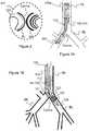
- Figure 1Ashows a schematic illustration of an exemplary endobronchial tube 100 according to an optional embodiment of the present invention placed within the right bronchi (BR).
- Figure 1Bshows a schematic illustration of an endobronchial tube 100 within the left bronchi (LB).
- Endobronchial tube 100is a dual lumen tube comprising an external wall 100w, a first tracheal ventilation lumen 110 and a second bronchial ventilation lumen 120.
- Wall 100wis common to both tracheal lumen 110 and bronchial lumen 120 wherein wall 100w defines the external surface of tube 100.
- an internal septum and/or midline partition 108defines the individual lumen into tracheal lumen 110 and bronchial lumen 120, Figure 8A-B .
- Tracheal lumen 110most preferably, has a distal end 114 ending within the trachea while the bronchial lumen 120 has a distal end 124 ending within the bronchi, left or right.
- tracheal lumen 110 and bronchial lumen 120are configured to have different lengths, wherein the bronchial lumen 120 extends past and/or distally to tracheal lumen 110.
- Each ventilation lumencomprises an inflatable cuff respectfully, tracheal cuff 112 and bronchial cuff 122.
- cuffs 112 and 122are individually controllable.
- Tube 100is places such that the tracheal lumen 110 is placed within the Trachea by way of cuff 112 proximally, above, the tracheal carina ('TC'). Most preferably the tracheal carina may be continually visualized with an image sensor 150c and light source 1501, Figure 9 .
- wall 100w of tube 100comprises a plurality of dedicated peripheral lumen dispersed about the periphery of wall 100w, Figure 8A-B .
- Tube 100can comprise at least two or more dedicated peripheral lumen; a first non-optional dedicated peripheral lumen provided as a dedicated image sensor lumen 150L provided for imaging the TC; and a second dedicated peripheral lumen provided in the form of a dedicated cleaning lumen 160 for clearing and/or cleaning the view of image sensor disposed in lumen 150L.
- tube 100is characterized in that it comprises a cleaning nozzle arrangement 162 about distal end 160d, Figures 7G-H .
- cleaning nozzle arrangement 162comprises a plurality of cleaning nozzles arranged about the distal end 160d and distally to image sensor arrangement 150 so as to ensure that a tube 100 is provided with a clear and unobstructed view of the TC, for example as shown in Figure 2 .
- Most preferably cleaning nozzle arrangementare optionally and preferably directed and/or aimed to clear the field of view immediately distal to image sensor arrangement 150 about the distal end 114 of tracheal ventilation lumen 110.
- cleaning nozzle arrangement 162may comprise at least two or more cleaning nozzles about distal end 160d.
- a cleaning nozzle arrangement 162comprising a plurality of cleaning nozzles about distal end 160d provides sufficient flushing and/or cleaning power and/or force and/or pressure so as to provide image sensor arrangement 150 with an unobstructed view by evacuating biological debris for example mucus or the like biological builds up in and about distal end 114, 150d and 160d.
- cleaning nozzle arrangement 162comprises a four cleaning nozzle arrangement 164 about image sensor arrarison150.
- Four cleaning nozzle arrangement 164includes a first primary cleaning nozzle 166 and at least three secondary cleaning nozzles collectively referred to as 168, as shown in Figures 7G-H .
- Most preferably arrangement 164may be arranged distally to one another in a linear sequential manner for example as shown in Figure. 7G-H .
- Most preferably primary cleaning nozzle 166may be configured to have a nozzle opening of about 0.8mm, and is most preferably disposed immediately and/or directly adjacent to the image sensor arrangement 150.
- Most preferably secondary cleaning nozzles 168may be configured to have a nozzle opening of about 0.6mm, and a disposed distally to primary cleaning nozzle 166.
- secondary cleaning nozzles 168may optionally be spaced apart equally, for example about 0.5mm.
- secondary cleaning nozzles 168may be spaced unequally distal to primary cleaning nozzle 164.
- Optionally cleaning nozzle arrangement 162 about distal end 160dmay be configured in optional geometric arrangements, wherein primary cleaning nozzle 166 is disposed nearest to image sensor arrangement 150 providing a first flushing and/or cleaning activity, while a plurality of secondary cleaning nozzle 168 are arranged distally thereto to provide a secondary flushing and/or cleaning activity, Figure 7I .
- Optionally cleaning nozzles 166, 168may be provided with an opening having a diameter from about 0.1mm to about 2mm.
- Optionally primary cleaning nozzle 166has a larger nozzle opening diameter than do secondary cleaning nozzles 168.
- Image sensor 150c and light source 1501are disposed within a first dedicated peripheral lumen 150L that is disposed within wall 110w.
- image sensor lumen 150Lcomprising image sensor 150c and light source 1501 may be integrated within tracheal lumen 110 about distal end 114, such that the distal end 150d is adjacent to distal end 114.
- the image sensor apparatus 150remains within its dedicated peripheral lumen 150L.
- image sensor arrangement 150comprising an image sensor 150c and a light source 1501 may be integrated within a dedicated channel or peripheral lumen 150L within a wall of the tracheal lumen 110.
- image sensor 150provides a cross sectional view 101, for example as shown in Figure 2 .
- image sensor arrangement 150are provided in the form of at least one or more light emitting diode ('LED') 1501 and image sensor 150c for example including but not limited to a CCD or CMOS, ( Figure 9 ) providing a view 101 showing the status of the bronchi, Figure 2 .
- 'LED'light emitting diode
- image sensor 150cfor example including but not limited to a CCD or CMOS, ( Figure 9 ) providing a view 101 showing the status of the bronchi, Figure 2 .
- Figure 2shows a schematic sectional view of the Tracheal Carina as seen from endobronchial tube 100, provided by image sensor and light source 150, allowing the visualization of bronchial cuff 122 disposed within the left bronchi BL, the patency of the left bronchi, the patency of the right bronchi, the tracheal carina, bronchial bifurcation, in a single field of view 101.
- image sensor 150when tube 100 is disposed with the right Bronchi BR as shown in FIG. 1A .
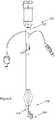
- Figure 3shows endobronchial double lumen tube system 50 comprising endobronchial tube 100 and optional various auxiliary devices that may be used in conjunction with and/or facilitate the use of tube 100.
- auxiliary devicesmay for example include but are not limited to stylet 10, Y-connector 12, air balance caps 14, an endobronchial tube connector assembly 20, straight or curved suction catheters (not shown) for cleaning secretions, or the like adjunct devices facilitating the use of tube 100 as is known in the art.
- Stylet 10most preferably is utilized to facilitate placement of tube 100, as is known and accepted in the art.
- Y-connector 12most preferably provides for simultaneously connecting both lumens of double lumen tube 100 to a single ventilation source.
- Endobronchial Tube connector assembly 20provides for individually connecting to tracheal lumen 110 and bronchial lumen 120.
- Connector assembly 20comprises a proximal end 22, distal end 28, and respective tracheal lumen connector portion 24 and bronchial connector portion 26.
- bronchial connector portion 26is a different color to tracheal connector portion 24 to ease the connection process of external equipment by medical staff.
- proximal end 22provides for connecting and/or otherwise associating the tube 100 at proximal end 102 at about the individual lumen tracheal lumen 110 and bronchial lumen 120 to auxiliary devices for example including but not limited to ventilation sources.
- distal end 24provides for coupling and/or otherwise associating with tube 100.
- Figure 3further provides a perspective view of a preferred double lumen endobronchial tube 100 comprising tracheal lumen 110 having a tracheal lumen distal end 114 and bronchial lumen 120 having a bronchial lumen distal end 124.
- Tube 100further comprises tracheal cuff 112, shown in its expanded state, provided for securely placing and/or anchoring tube 100 within the trachea while ventilating the lungs through tracheal lumen 110.
- Tube 100further comprises bronchial cuff 122, shown in its expanded and/or inflated state, provided for securely placing and/or anchoring tube 100 within the bronchi, left or right.
- cuff 122provides for selectively controlling the ventilation to the bronchial arch wherein it is placed (left or right). For example ventilation to either the left or right bronchi may be completely blocked so as to allow a procedure on the respective lung (for example right) while allowing the ventilation of the other lung (for example left) via tracheal lumen 110.
- tracheal cuff 112may be inflated and/or deflated via cuff tracheal connector 118.
- bronchial cuff 122may be inflated and/or deflated via cuff bronchial connector 128.
- injection tube connector 130provides an access point to a dedicated lumen about each of the tracheal tube 110 and bronchial tube 120, preferably for delivering drugs, suctioning, or liquids about tracheal distal 114 and/or bronchial lumen distal end 124.
- Figures 4Aprovide a further perspective view of endobronchial tube 100, showing image sensor connector 158.
- image sensor connector 158is provided in the form of a USB connector that provides both for image and power supply to image sensor 150 disposed in a dedicated lumen near distal end 114.
- image sensor and illumination 150may be rendered functional when connected to a display and power source (not shown) via connector 158.
- connector 158is provided with a ridged surface to enable better grip and easier connection or disconnection to/from peripheral equipment.
- Figure 4Bprovides a close up view showing the image sensor notch 152 disposed about the proximal end of image sensor lumen 150L providing an exit point for image sensor conducting wires 154, most preferably provided for both image transfer and power supply to image sensor and illumination source 150.
- Image sensor notch 152is preferably disposed 22.5mm from the proximal end 102 of tube 100 and preferably has a diameter of about 1.5mm.
- Figure 5provides a further perspective view of tube 100 provided from a face on view showing the separation of tracheal lumen 110 and bronchial lumen 120 at distal end 104 of tube 100.
- Figure 6provides a further schematic illustrative depiction of tube 100 showing a perspective view of tube 100 with the bronchial cuff 122 and tracheal cuff 112 removed.
- Figure 6Ashows the curvature provided at both the medial section 106 and distal end 104 therein defining a medial curvature 106a and a distal curvature 104a. Curvatures 104a and 106a are provided to so that tube 100 fits within the upper airway tract's anatomy.
- medial curvature 106ais provided for the ease of accessing and introducing tube 100 within the trachea through the oral cavity and pharynx. Most preferably, curvature 106a, is provided with an angle from about 100 degrees to about 160 degrees.
- distal curvature 104ais provided for ease of accessing and introducing distal end 104 into one of the bronchi, left or right.
- distal curvature 104amay be specific for individual left or right endobronchial tubes.
- distal curvaturemay be configured to be from about 25 degrees to about 70 degrees and optionally and preferably about 35 degrees as shown.
- the length of tube 100may be provided with a length from about 200mm to about 550mm.
- the length of tube 100may be selected in accordance with a user's anatomy.
- endobronchial tube 100may be provided with different sizes, length, diameters as known and accepted in the art.
- tube 100may be provided with a gauge from about 8.66 mm (26 Fr) to about 14.8mm (44Fr)
- the external diameter of tube 100may be provided in varying gauges and/or sizes for example including but not limited to 9.3mm, 10.7mm, 11.7mm, 13mm and 13.7mm (28 Fr, 32 Fr, 35 Fr, 37 Fr, 39 Fr and 41Fr, respectively). It is common in the art to indicate the gauge of the tube 100 in units French, 1Fr being equivalent to 0.33mm in SI units.
- the length and diameter (also referred to as gauge) of tube 100may be correlated with one another.
- Figure 7Ashows a close up view of distal end 104 of tube 100 shown in Figure 6 providing a close up view.
- Figure 7Afurther shows a close up view of curvature 104a showing the flaring 114f of distal end 104 from wall 100w of tracheal lumen into the side portion of bronchial lumen 120, most preferably forming and distal end flaring 114f.
- Most preferably flaring 114f at distal end 104afurther provides for placing and/or approximating the distal ends 150d, 160d of the peripheral dedicated lumen 150L, 160 near the distal end 114 of ventilation lumen 110, for example as shown in Figure 7C .
- flaring 114fforms a cover and/or cap over the distal end of the dedicated peripheral lumen 150d and 160d adjacent to distal end 114 of ventilation lumen 110.
- distal end flaring 114ffacilitates placement of a cleaning nozzle arrangement 162 about the distal end 160d of cleaning lumen 160, for example as shown in Figures 7C and 7G .
- flaring 114fmay facilitate the cleaning function provided by arrangement 162.
- Figures 7A-Eshow various close up view of distal end 104 specific to curvature 104a showing the flaring 114f and tapering of distal end 104 from the tracheal lumen 110 into the side portion of bronchial lumen 120.
- Figures 7D-Eprovide additional close up views of the distal end 150d and cleaning lumen 160 showing an optional primary cleaning nozzle 166 in the form of a single cleaning nozzle 156, most preferably provided for cleaning image sensor 150c.
- Optionally cleaning nozzle 156may be provided with an opening having a diameter from about 0.1mm to about 2mm, more preferably from about 0.4mm to about 0.9mm, optionally about 0.6mm or 0.8 mm.
- Image sensor 150is most preferably provided in a dedicated lumen 150L that spans the length of tube 100. Most preferably lumen 150 is disposed between tracheal lumen 110 and bronchial lumen 120.
- distal end of lumen 150Lprovides for visualizing the carina and the bronchial cuff 122, for example as shown in Figure 2 .
- image sensor lumen 150Lis variable along the length of tube 100. Most preferably image sensor lumen 150 is smallest at the proximal end 102 and largest at the distal end 104. Optionally and preferably at proximal end 102 sensor lumen 150L is configured to have an elliptical cross-section. Optionally and preferably at distal end of sensor lumen 150L is configured to have a circular cross-section.
- a dedicated cleaning lumen 160that has a distal end defining a cleaning nozzle 156, as shown, providing for cleaning image sensor 150 about its distal end.
- cleaning nozzle 156is provided with a curvature and/or angle so as to direct cleaning solution, fluid, gas or the like flowing fluid toward and/or away from integrated image sensor 150 and more preferably image sensor 150c.
- cleaning lumen 160may be utilized to clear mucus or the like biological obstruction from in front of integrated image sensor 150 by flushing with a flowing fluid, for example a liquid or gas, from the proximal end of lumen 160 through to its distal end 160d and forming at least one or more cleaning nozzle 156, 166, 168 or a cleaning nozzle arrangement 162, 164.
- cleaning lumen 160may be used to clear the viewing field of integrated image sensor 150 by applying suctioning therein suctioning in front of the field of view to keep it clean.
- Figure 7Fshows a close up view of cleaning nozzle 156 that is directed toward image sensor 150 about the distal end of lumen 150L.
- cleaning nozzle 156is configured such that it provides for maintaining an open field of view of the Tracheal Carina for integrated images sensor 150.
- Figure 7E-Fshow an optional cleaning nozzle arrangement having a single cleaning nozzle 156, about the tubes distal portion 104
- Figures 7G-Hshow a preferred embodiment of the present invention for a ventilation tube 100 having a four cleaning nozzle arrangement 164 comprising a plurality of cleaning nozzles, including a primary cleaning nozzle 166 and three secondary cleaning nozzle 168.
- Figure 7Gshows an illustrative diagram of the preferred embodiment showing cleaning nozzle arrangement 162 about the distal end 114.
- Most nozzle arrangement 162comprises a primary nozzle 166 and a plurality of secondary nozzles 168, as previously described.
- a preferred embodimentcomprises three secondary nozzles 168 disposed distally to primary nozzle 166 and image sensor 150.
- the cleaning nozzles comprising nozzle arrangement 162are directed so as to clean and/or clear and/or suction any biological debris for example mucus that forms distally to image sensor 150.
- cleaning nozzles 166, 168may be provided with an opening having a diameter from about 0.1mm to about 2mm.
- Optionally primary cleaning nozzle 166has a larger nozzle opening diameter than do secondary cleaning nozzles 168.
- Figure 7Hprovides a close up view of four cleaning nozzle arrangement 164 about distal end 114, as previously described and according to a preferred embodiment of the present invention, wherein the nozzle arrangement is characterized by a distally linear arrangement wherein primary nozzle 166 is adjacent to image sensor 150 while secondary nozzles 168 are positioned distally therefrom, optionally and preferably equidistant from one another.
- Figure 7Ishows an optional cleaning nozzle arrangement 162 where a plurality of secondary cleaning nozzles 168 are arranged about image sensor 150 in a circumferential arrangement, for example as shown.
- the distal end 160d of cleaning lumen 160may be curved such that the distal end 160d and nozzle arrangements 162, 164 are most preferably directed toward the distal end 150d of image sensor lumen 150L therein providing for forming a cleaning nozzle arrangement 162 that is optionally and preferably directed toward image sensor 150.
- tube 100may be provided with at least two or more peripheral cleaning lumen 160 for example as shown in figure 8A-B .
- a first cleaning lumenmay be provided for flushing biological obstruction while a second cleaning lumen may be provided for suctioning biological obstructions away from the distal end 114.
- a plurality of cleaning lumen 160may be disposed on opposite sides of integrated image sensor 150.
- a plurality of cleaning lumen 160may be configured to cooperate with one another, for example a first lumen would flush biological obstructions toward a second cleaning lumen where the obstruction is carried away by suctioning.
- At least two or more cleaning lumen 160may be utilized concertedly to either suction or flush obstructions distal to integrated image sensors 150, therein most preferably ensuring an open viewing field.
- a plurality of cleaning lumenmay be provided with different diameters and or sizes.
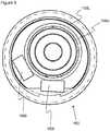
- Figure 8Ashows a cross sectional view of tube 100 about its proximal end 102 having tracheal lumen 110 and a bronchial lumen 120 defined on either side of a midline partition 108.
- tube 100comprises a plurality of peripheral lumen disposed internally and/or within the walls of tube 100.
- a plurality of peripheral lumenmay be disposed about the circumference of tube 100, within wall 100w, and span essentially the length of tube 100, about the tracheal lumen 110 and/or bronchial lumen 120.
- the peripheral lumenmay for example include but is not limited to a suctioning lumen, cuff inflating lumen, electronic lumen, image sensor lumen, cleaning lumen, injection tube lumen, or the like.
- tube 100includes a dedicated lumen 150L provided for image sensor and integrated illumination source 150.
- lumen 150Lprovides for housing the image sensor 150 at its distal end ( Figure 7E-F ) and housing image sensor conducts for example in the form of a wire 154, disposed along the length of lumen 150L, and a image sensor notch 152 disposed near the proximal end of lumen 150L allowing image sensor conductor 154 and connector 158 to be disposed external to tube 100.
- lumen 150Lis disposed about the anterior portion of tube 100 about the middle of the cross-section of tube 100. Most preferably lumen 150L is disposed anterior to partition 108. Optionally lumen 150L may be disposed about the posterior portion of tube 108 therein posterior to partition 108.
- lumen 150LMost preferably on both sides of lumen 150L are dedicated lumen running along the length of tube 100 and most preferably running parallel with lumen 150L. Optionally and preferably at least one or more of lumen are provided as a dedicated cleaning lumen 160. Optionally both lumen flanking lumen 150L may be dedicated cleaning lumen 160.
- tube wallfurther comprises lumen 112L and 122L respectively corresponding to tracheal lumen 110 and bronchial lumen 120.
- lumen 112L and 122Lare provided for inflating and/or deflating cuffs 112 and 122 respectively.
- Figure 8Bshows the same image as in Figure 8A however showing the cross-section near tracheal lumen distal end 114 of tube 100.
- image sensor lumen 150Lis provided with a lumen having a larger radius than that provided at the proximal end 102 as shown in Figure 8A .
- tube 100is expanded about distal end 104 and lumen 150L to accommodate integrated image sensor 150.
- image sensor lumen 150 about the external surface of tube 110is widened and/or expanded 1.5mm to 5mm from distal end 114 of tracheal lumen 110.
- Figure 9shows a close up bottom-up view of the integrated image sensor 150 within dedicated electronics lumen 150L disposed within the wall of the endobronchial tube 100, showing image sensor 150c optionally and preferably provided in the form of a CCD or CMOS or the like, and illumination source 1501 most preferably provided in the form of at least one and more preferably at least two or more LED, as shown.
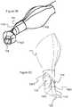
- figure 10ashows a perspective view of an exemplary endobronchial tube depicting the tube inserted into a laryngeal mask according to an optional embodiment of the present invention
- figures 10b and 10cwhich are respectively perspective and frontal views of an exemplary image sensor connector according to an optional embodiment of the present invention.
- the laryngeal mask airway device or laryngoscope maskis a well-known device in the art that is useful for establishing airways in unconscious patients.
- US 4,509,514is one of the many publications that describe laryngeal mask airway devices and is a useful source of background information.
- the laryngeal masktypically comprises a curved or flexible tube opening at one end into the interior of a hollow mask portion shaped to conform to and to fit readily into the actual and potential space behind the larynx and to seal around the circumference of the laryngeal inlet without penetrating into the interior of the larynx.
- the devicethus constitutes a laryngeal mask.
- the mask portion of the devicemay have an inflatable periphery which is adapted to form the seal around the laryngeal inlet.
- the mask portionmay have an inflatable posterior part which is adapted to press against the back of the throat and thereby increase the sealing pressure around the laryngeal inlet.
- Figure 10adepicts endobronchial tube 100 placed within laryngeal mask 180.
- the endobronchial tube 100is commonly inserted into a laryngeal mask 180 and then both are inserted into the patient.
- Use of the tube with the laryngeal maskeases the insertion and positioning of both.
- the camera of tube 100helps guide mask 180 so that mask 180 can be properly positioned against the trachea.
- Mask 180provides a guide for tube 100 to ease the positioning thereof in the trachea.
- Arrow 188shows the direction of removal of the mask 180.
- tube 100passes through in the direction shown by arrows 186.
- Auxiliary devicessuch as Y-connector 12 are preferably disconnected form tube 100 so that it may pass though mask 180 and more specifically through mask opening 182 which represents the smallest inner diameter of mask 180.
- Opening 182typically has a diameter of 11-11.5mm in laryngeal masks known in the art.
- Tube 100is therefore preferably sized so that it may completely pass through opening 182.
- image sensor connector 158is preferably provided with rounded sides 190 (as opposed to the rectangular sides of connectors commonly known in the art) to allow it to pass through opening 182.
- connector 158preferably has a maximum diameter of 10.5mm so that it can fit through opening 182.
- Figure 10cshows the dimensions of such an exemplary embodiment of connector 158 where the radius defining the rounded side 190 of the connector is 5.25mm.
Landscapes
- Health & Medical Sciences (AREA)
- Life Sciences & Earth Sciences (AREA)
- Surgery (AREA)
- Engineering & Computer Science (AREA)
- Veterinary Medicine (AREA)
- Public Health (AREA)
- General Health & Medical Sciences (AREA)
- Animal Behavior & Ethology (AREA)
- Biomedical Technology (AREA)
- Heart & Thoracic Surgery (AREA)
- Physics & Mathematics (AREA)
- Optics & Photonics (AREA)
- Medical Informatics (AREA)
- Molecular Biology (AREA)
- Radiology & Medical Imaging (AREA)
- Pathology (AREA)
- Nuclear Medicine, Radiotherapy & Molecular Imaging (AREA)
- Biophysics (AREA)
- Pulmonology (AREA)
- Emergency Medicine (AREA)
- Anesthesiology (AREA)
- Hematology (AREA)
- Otolaryngology (AREA)
- Physiology (AREA)
- Endoscopes (AREA)
- Microelectronics & Electronic Packaging (AREA)
- Instruments For Viewing The Inside Of Hollow Bodies (AREA)
Description
- The present invention relates to upper airway tubes and in particular, to an endobronchial tube with an integrated image sensor and light source having a cleaning nozzle arrangement.
- Respiratory tubes for example endobronchial tubes, endotracheal tubes, tracheostomy tubes are used to ventilate at least a portion of the respiratory system or lungs of a subject. Such respiratory tubes may be inserted in a number of ways via a non-invasive approach through an orifice or cavity such as the oral or nasal cavity. Alternatively such tubes may be introduced to a body via a minimally invasive external incision creating a port for tube insertion for example through the trachea in a tracheotomy procedure.
- Such respiratory tubes may be provided as double lumen tubes, or single lumen tubes for selectively ventilating a portion of the respiratory system. For example endobronchial tubes, whether, double lumen tubes or a single lumen tube may be utilized for one- lung ventilation procedures or for selective lung ventilation of the left or right bronchi, during one- lung ventilation procedures.
- The present invention provides an endobronchial tube for respiratory intubation of a patient as hereinafter set forth in Claim 1 of the appended claims.
- An endobronchial tube for respiratory intubation of a patient comprising: a first lumen having an open distal end for location, when in use, proximally to the carina within the trachea of the patient, and having a first inflatable cuff; a second lumen longer than the first lumen and having an open distal end to extend, during use, distally past the carina for location within one of the left bronchial branch and right bronchial branch and having a second inflatable cuff; a further lumen; an outer wall enclosing said first lumen, said second lumen and said further lumen; an image sensor and illumination source; and an image sensor connector disposed at the proximal end of said outer wall is disclosed in
CN 201 862 108 U . US2002/108610 discloses a method and apparatus for endotracheal intubation with simultaneous oxygenation/ventilation employs a curved guide and a light wand to ensure proper placement of the endotracheal tube in the patient's airway. The light wand has an elongated flexible member with a light source at its distal tip. The wand is inserted through an endotracheal tube until the light is adjacent to the distal end of the endotracheal tube. A curved guide is inserted into the patient's mouth and upper airway so that its distal end is positioned above the larynx. The wand and endotracheal tube are then advanced along the guide until the distal end of the endotracheal tube passes through the larynx and the light source is externally observable at a predetermined location through the anterior tracheal wall.US2012/302833 discloses various embodiments of an intubation system including a tracheal tube and an illumination assembly that is removably couplable to a tubular body of the tracheal tube. The tracheal tube may be a double lumen tracheal tube having a first cuff that is adapted to be inflated to seal against the walls of a patient's trachea and a second cuff that is adapted to be inflated to seal against the walls of the patient's bronchial stem. The illumination assembly may have one or more illumination devices that are adapted to produce light within the patient's trachea, the patient's bronchial stem, or both when the illumination assembly is coupled to the tubular body.US2012/172664 discloses systems and methods that utilize a multi-lumen tube with an integral visualization apparatus, such as a camera. The multi-lumen tracheal tube system may include a camera apparatus that is positioned to facilitate left or right bronchial intubation. In addition, the camera apparatus may be a unitary assembly that functions to hold and position the camera relative to the tube and provides an acceptable profile for comfortable intubation. The camera apparatus may include additional components, such as integral light sources and flushing or cleaning devices to remove any buildup from the camera or optical components.- In order to perform one-lung ventilation procedures without complications, the position of the respiratory tube placed within either the left or right bronchi and the trachea must be closely monitored or at least confirmed prior to initiating a procedure. Various technologies are available to confirm the tube's placement, for example capnograph, auscultation, bronchoscope and x-ray.
- However these procedures take time, technique and skill to perform and therefore it is not feasible to monitor the tube's placement continuously. In particular, when the subject is moved during a procedure, the tube's location may change leading to potentially dangerous displacement of the tube possibly suffocating the subject or inappropriate ventilation of the patient, for example not ventilating the correct portion of the respiratory system.
- Verification by means of a bronchoscope is currently the gold standard, but none of the mentioned confirmation techniques provide continuous monitoring of the carina or provide for correct tube positioning. Furthermore, drawbacks with respect to the design and sensitivity of the bronchoscope, render its cleaning process elaborate and often inefficient and costly process, that may lead to cross infection between subjects.
- The invention meets the demand for an endobronchial tube capable of continuously and seamlessly inspecting the location and implantation of the endobronchial tube relative to the tracheal carina. Furthermore, an embodiment of the invention provides an endobronchial tube that is capable of maintaining a clear field of view of the tracheal carina.
- Embodiments of the present invention overcome the deficiencies of the background by providing an endobronchial tube having an integrated image sensor with a corresponding light source and integrated means for maintaining the field of view provided by the image sensor, for example in the form of a cleaning nozzle and/or lumen,.
- The present invention, which is defined in independent claim 1 and the dependent claims 2-7, provides a respiratory tube designed for oral or nasal insertion via the trachea and into a lung to inspect and/or visualize the carina, to maintain airway patency and/or deliver anesthetic, inhalation agent or other medical gases, and secure ventilation.
- The endobronchial tube of embodiments of the invention may be made of medical grade materials for example including but not limited to plastic, rubber, polymers or silicone or the like materials as is known in the art.
- The endobronchial tube of the present invention provides for continuous monitoring of the Tracheal Carina (herein "TC"), allowing a user, physician, nurse, or caregiver to verify the correct placement of the endobronchial tube while maintaining a clear field of view of the TC.
- The endobronchial tube includes an integrated image sensor, optionally and preferably in the form of CCD or CMOS camera provided for visualizing the carina to confirm the correct placement of the tube within the trachea and bronchi, assuring correct ventilation during procedures for example including but not limited to one lung ventilation procedures, or the like.
- The integrated camera and light source provide continuous verification of the correct placement of the endobronchial tube. The continuous placement verification allows a caregiver the opportunity to detect any dangerous situation, for example cuff dislodgement, providing sufficient time to react to the situation as is necessary. Moreover blood and secretion accumulation or any other unexpected incidents during surgery, which might cause risk to the patient, may be observed.
- A preferred embodiment of the present invention provides for an endobronchial tube with an integrated image sensor, for example including but not limited to CCD or CMOS camera, with a corresponding light source, for example including but not limited to a Light Emitting Diode ('LED') while optimizing the lumen patency for both adequate airflow performance through the tube.
- The image sensor may further be provided with at least one or more adjacent and integrated cleaning nozzle to ensure an open field of view, for example of the tracheal carina, distal to the image sensor.
- The integrated cleaning nozzle may be configured to be wholly embedded within the tube's wall in the form of a dedicated cleaning lumen running the length of the tube. Most preferably the length of the dedicated image sensor lumen is provided paralleled with the length of the tracheal lumen, therein both tracheal lumen and image sensor lumen are of essentially the same length. Optionally the length of the dedicated image sensor lumen may be provided according to the length of the bronchial lumen.
- Optionally the endobronchial tube may be provided with two dedicated image sensor lumen. Optionally a first dedicated image sensor lumen is provided according to the length of the tracheal lumen and a second dedicated image sensor lumen is provided according to the length of the bronchial lumen.
- Optionally the bronchial cuff may be provided in varying shapes so as to better fit the bronchi for example include but is not limited to spherical, elliptical, helical, hourglass, trapezoidal, or the like.
- Optionally different bronchial cuff configured and shaped according to anatomy and placement location, for example anatomy based on configuration of a cuff for left bronchi placement and for right bronchi placement.
- Within the context of this application the term endobronchial tube may be used interchangeably with any one of tracheobronchial tube, double lumen tube, double lumen endobronchial tube, double lumen endotracheal tube, to collectively refer to a tube and/or catheter utilized for selectively ventilating a subject via both lungs, one of the lungs or a portion of one or both of the lungs.
- A preferred embodiment of the present invention provides for an endobronchial tube with an external wall and an internal septum defining at least two ventilation lumen of different lengths for selectively associating with a patient about at least two locations relative to the tracheal carina.
- Most preferably the tube includes a first ventilation lumen having an open distal end that associates proximally to the carina within the trachea, with a first inflatable cuff and a second ventilation lumen having an open distal end that extends distally, past the carina and associates within one of the left bronchial branch or right bronchial branch with a second inflatable cuff.
- Preferably the tube further includes at least two peripheral lumens of different lengths, that are disposed within the tube's external wall and run parallel to one of the ventilation lumen.
- Preferably the first peripheral lumen includes an image sensor and light source disposed proximal to the distal end of the first ventilation lumen, and configured to provide an image of the Tracheal bifurcation of the Tracheal Carina, the openings of the Left Bronchial branch, and the opening Right Bronchial branch.
- Preferably the second peripheral lumen defines a dedicated cleaning lumen, having a distal end disposed distally to the distal end of the first peripheral lumen about the image sensor and light source, the second peripheral lumen having a distal end with a plurality of variably sized openings, wherein each opening forms a cleaning nozzle distal to the image sensor, the second peripheral lumen configured to conduct a flowing fluid to maintain a clear field of view distal to the image sensor.
- Optionally and preferably the distal end of the second peripheral lumen includes four openings defining four cleaning nozzles about the image sensor. The four openings are preferably arranged distally to one another in a linear sequential manner. The first opening having an opening of about 0.8mm defining the first cleaning nozzle directly adjacent to the image sensor. The remaining three openings may be configured to have a nozzle opening of about 0.6mm.
- Optionally the cleaning nozzles may be variably spaced relative to one another and/or may be uniformly spaced relative to one another about the distal end of the second peripheral lumen.
- Optionally, the tube may further include an additional peripheral lumen running along the second ventilation lumen providing for a second image sensor and light source providing an image of the Right bronchi or Left bronchi, and dedicated cleaning lumen.
- Optionally the first and second peripheral lumen may run parallel with the second ventilation lumen rather than the first ventilation lumen.
- Optionally the image sensor may be a CCD image sensor or CMOS image sensor.
- Optionally, the first peripheral lumen further includes a light source disposed proximal to the distal end and adjacent to the image sensor.
- Optionally the light source may be selected from the group consisting of a LED, optical fiber, waveguide, light guide, and any combination thereof.
- Optionally the first peripheral lumen comprising an image sensor and light source may be disposed within a dedicated channel embedded within a wall of the first lumen.
- Most preferably the image sensor may be associated with an auxiliary device for example including but not limited to a display and power supply at the proximal end of the tube most preferably about the first lumen, through a single dedicated connector for example including but not limited to a USB connector.
- Optionally the endotracheal tube may be adapted for non-invasive insertion through the oral cavity or nasal cavity.
- Optionally the endotracheal tube may be adapted for insertion through an external port or incision.
- Optionally the endotracheal tube may be adapted for insertion through a surgical procedure or other invasive procedure.
- Preferably the endotracheal tube has a medial curvature with an angle from 100 degrees to 160 degrees.
- Preferably the endotracheal tube has a distal curvature with an angle from 25 degrees to 70 degrees.
- Preferably the endotracheal tube is adapted for use with a laryngeal mask so that the tube and mask may be together inserted into a patient and that the mask may be removed from the patient following inflation of the first and second inflatable cuffs.
- Unless otherwise defined, all technical and scientific terms used herein have the same meaning as commonly understood by one of ordinary skill in the art to which this invention belongs. The materials, methods, and examples provided herein are illustrative only and not intended to be limiting.
- The invention is herein described, by way of example only, with reference to the accompanying drawings. With specific reference now to the drawings in detail, it is stressed that the particulars shown are by way of example and for purposes of illustrative discussion of the preferred embodiments of the present invention only, and are presented in order to provide what is believed to be the most useful and readily understood description of the principles and conceptual aspects of the invention. In this regard, no attempt is made to show structural details of the invention in more detail than is necessary for a fundamental understanding of the invention, the description taken with the drawings making apparent to those skilled in the art how the several forms of the invention may be embodied in practice.
- In the drawings:
Figures 1A-B show schematic illustrations of an exemplary endobronchial tube according to an optional embodiment of the present invention;Figure 1A shows the endobronchial tube within the right bronchi;Figure 1B shows the endobronchial tube within the left bronchi;Figure 2 shows a schematic sectional view of the Tracheal Carina as seen from the endobronchial tube according to an optional embodiment of the present invention;Figure 3 shows a perspective view of an exemplary endobronchial tube according to an optional embodiment of the present invention;Figure 4A shows a perspective view of an exemplary endobronchial tube according to an optional embodiment of the present invention;Figure 4B shows a close up view of notch exit point for the image sensor connector according to the present invention;Figure 5 shows a perspective view of an exemplary endobronchial tube according to an optional embodiment of the present invention;Figure 6 shows a perspective view of an exemplary endobronchial tube according to an optional embodiment of the present invention, depicting the curvature of the tube;Figures 7A-F shows varying close up views of the distal end of the endobronchial tube according to optional embodiments of the present invention;Figures 7G-H show a preferred embodiment of the cleaning nozzle arrangement according to the present invention;Figures 7I shows an optional embodiment according to the present invention;Figures 8A-B show cross-sectional views about different portions of the endobronchial tube according to optional embodiments of the present invention;Figure 9 shows a close up view of the image sensor with integrated light source within a dedicated lumen disposed within the wall of the endobronchial tube according to an optional embodiment of the present invention;Figure 10a shows a perspective view of an exemplary endobronchial tube inserted into a laryngeal mask according to an optional, illustrative embodiment of the present invention; andFigures 10b and 10c respectively show perspective and frontal views of an exemplary image sensor connector according to an optional, illustrative embodiment of the present invention.- The principles and operation of the present invention may be better understood with reference to the drawings and the accompanying description. The following reference labels listed below are used throughout the drawings to refer to objects having similar function, meaning, role, or objective.
- 10
- Stylet;
- 12
- Y-connector;
- 14
- Air Balance Cap;
- 20
- Endobronchial Tube connector assembly;
- 22
- Endobronchial Tube connector proximal end;
- 24
- Tracheal lumen connector portion;
- 26
- Bronchial lumen connector portion;
- 28
- Endobronchial Tube connector distal end;
- 50
- endobronchial tube system;
- 100
- endobronchial tube;
- 100w
- tube external wall;
- 101
- sectional view;
- 102
- tube proximal end;
- 104
- tube distal end;
- 104a
- distal curvature;
- 106
- tube medial portion;
- 106a
- medial curvature;
- 108
- midline partition;
- 110
- tracheal lumen;
- 111
- tracheal lumen connector;
- 112
- tracheal cuff;
- 112n
- tracheal cuff notch;
- 114
- tracheal lumen distal end;
- 116
- tracheal lumen proximal end;
- 118
- tracheal cuff connector;
- 120
- bronchial lumen;
- 122
- bronchial cuff;
- 124
- bronchial lumen distal end;
- 126
- bronchial lumen proximal end;
- 128
- bronchial cuff connector;
- 130
- injection tube connector;
- 150
- image sensor arrangement;
- 150c
- image sensor;
- 150d
- image sensor lumen distal end;
- 1501
- illumination source;
- 150L
- image sensor lumen;
- 152
- image sensor notch;
- 154
- image sensor conductor;
- 156
- image sensor single cleaning nozzle;
- 158
- image sensor connector;
- 160
- cleaning lumen;
- 160d
- cleaning lumen distal end;
- 162
- cleaning nozzle arrangement;
- 164
- four cleaning nozzle arrangement;
- 166
- primary cleaning nozzle;
- 168
- secondary cleaning nozzles;
- 180
- laryngeal mask
- 182
- mask opening
- TR
- Trachea;
- TC
- Tracheal Carina;
- BR
- Right Bronchi;
- BL
- Left Bronchi.
Figure 1A shows a schematic illustration of an exemplaryendobronchial tube 100 according to an optional embodiment of the present invention placed within the right bronchi (BR).Figure 1B shows a schematic illustration of anendobronchial tube 100 within the left bronchi (LB).Endobronchial tube 100 is a dual lumen tube comprising anexternal wall 100w, a firsttracheal ventilation lumen 110 and a secondbronchial ventilation lumen 120.Wall 100w is common to bothtracheal lumen 110 andbronchial lumen 120 whereinwall 100w defines the external surface oftube 100. Most preferably an internal septum and/ormidline partition 108 defines the individual lumen intotracheal lumen 110 andbronchial lumen 120,Figure 8A-B .Tracheal lumen 110, most preferably, has adistal end 114 ending within the trachea while thebronchial lumen 120 has adistal end 124 ending within the bronchi, left or right. Thereintracheal lumen 110 andbronchial lumen 120 are configured to have different lengths, wherein thebronchial lumen 120 extends past and/or distally totracheal lumen 110. Each ventilation lumen comprises an inflatable cuff respectfully,tracheal cuff 112 andbronchial cuff 122. Optionally and preferably cuffs 112 and 122 are individually controllable.Tube 100 is places such that thetracheal lumen 110 is placed within the Trachea by way ofcuff 112 proximally, above, the tracheal carina ('TC'). Most preferably the tracheal carina may be continually visualized with animage sensor 150c andlight source 1501,Figure 9 .- Most preferably
wall 100w oftube 100 comprises a plurality of dedicated peripheral lumen dispersed about the periphery ofwall 100w,Figure 8A-B .Tube 100 can comprise at least two or more dedicated peripheral lumen; a first non-optional dedicated peripheral lumen provided as a dedicatedimage sensor lumen 150L provided for imaging the TC; and a second dedicated peripheral lumen provided in the form of adedicated cleaning lumen 160 for clearing and/or cleaning the view of image sensor disposed inlumen 150L. - Most preferably
tube 100 according to the present invention is characterized in that it comprises acleaning nozzle arrangement 162 aboutdistal end 160d,Figures 7G-H . Most preferably cleaningnozzle arrangement 162 comprises a plurality of cleaning nozzles arranged about thedistal end 160d and distally to imagesensor arrangement 150 so as to ensure that atube 100 is provided with a clear and unobstructed view of the TC, for example as shown inFigure 2 . Most preferably cleaning nozzle arrangement are optionally and preferably directed and/or aimed to clear the field of view immediately distal to imagesensor arrangement 150 about thedistal end 114 oftracheal ventilation lumen 110. - Optionally and most preferably cleaning
nozzle arrangement 162 may comprise at least two or more cleaning nozzles aboutdistal end 160d. Most preferably acleaning nozzle arrangement 162 comprising a plurality of cleaning nozzles aboutdistal end 160d provides sufficient flushing and/or cleaning power and/or force and/or pressure so as to provideimage sensor arrangement 150 with an unobstructed view by evacuating biological debris for example mucus or the like biological builds up in and aboutdistal end - Most preferably cleaning
nozzle arrangement 162 comprises a fourcleaning nozzle arrangement 164 about image sensor arranement150. Fourcleaning nozzle arrangement 164 includes a firstprimary cleaning nozzle 166 and at least three secondary cleaning nozzles collectively referred to as 168, as shown inFigures 7G-H . - Most preferably
arrangement 164 may be arranged distally to one another in a linear sequential manner for example as shown inFigure. 7G-H . Most preferablyprimary cleaning nozzle 166 may be configured to have a nozzle opening of about 0.8mm, and is most preferably disposed immediately and/or directly adjacent to theimage sensor arrangement 150. Most preferablysecondary cleaning nozzles 168 may be configured to have a nozzle opening of about 0.6mm, and a disposed distally toprimary cleaning nozzle 166. - Optionally
secondary cleaning nozzles 168 may optionally be spaced apart equally, for example about 0.5mm. Optionallysecondary cleaning nozzles 168 may be spaced unequally distal toprimary cleaning nozzle 164. - Optionally cleaning
nozzle arrangement 162 aboutdistal end 160d may be configured in optional geometric arrangements, whereinprimary cleaning nozzle 166 is disposed nearest toimage sensor arrangement 150 providing a first flushing and/or cleaning activity, while a plurality ofsecondary cleaning nozzle 168 are arranged distally thereto to provide a secondary flushing and/or cleaning activity,Figure 7I . - Optionally cleaning
nozzles primary cleaning nozzle 166 has a larger nozzle opening diameter than dosecondary cleaning nozzles 168.Image sensor 150c andlight source 1501 are disposed within a first dedicatedperipheral lumen 150L that is disposed within wall 110w. Optionally and most preferablyimage sensor lumen 150L comprisingimage sensor 150c andlight source 1501 may be integrated withintracheal lumen 110 aboutdistal end 114, such that thedistal end 150d is adjacent todistal end 114. Optionally and most preferably theimage sensor apparatus 150 remains within its dedicatedperipheral lumen 150L. Optionally and most preferablyimage sensor arrangement 150,Figure 9 , comprising animage sensor 150c and alight source 1501 may be integrated within a dedicated channel orperipheral lumen 150L within a wall of thetracheal lumen 110. Most preferablyimage sensor 150 provides a crosssectional view 101, for example as shown inFigure 2 . - Most preferably
image sensor arrangement 150 are provided in the form of at least one or more light emitting diode ('LED') 1501 andimage sensor 150c for example including but not limited to a CCD or CMOS, (Figure 9 ) providing aview 101 showing the status of the bronchi,Figure 2 . Figure 2 shows a schematic sectional view of the Tracheal Carina as seen fromendobronchial tube 100, provided by image sensor andlight source 150, allowing the visualization ofbronchial cuff 122 disposed within the left bronchi BL, the patency of the left bronchi, the patency of the right bronchi, the tracheal carina, bronchial bifurcation, in a single field ofview 101. Optionally a similar view may be provided withimage sensor 150 whentube 100 is disposed with the right Bronchi BR as shown inFIG. 1A .Figure 3 shows endobronchial doublelumen tube system 50 comprisingendobronchial tube 100 and optional various auxiliary devices that may be used in conjunction with and/or facilitate the use oftube 100.- Optionally auxiliary devices may for example include but are not limited to
stylet 10, Y-connector 12, air balance caps 14, an endobronchialtube connector assembly 20, straight or curved suction catheters (not shown) for cleaning secretions, or the like adjunct devices facilitating the use oftube 100 as is known in the art. Stylet 10 most preferably is utilized to facilitate placement oftube 100, as is known and accepted in the art.- Y-
connector 12 most preferably provides for simultaneously connecting both lumens ofdouble lumen tube 100 to a single ventilation source. - Endobronchial
Tube connector assembly 20 provides for individually connecting totracheal lumen 110 andbronchial lumen 120.Connector assembly 20 comprises aproximal end 22,distal end 28, and respective tracheallumen connector portion 24 andbronchial connector portion 26. In an optional embodiment,bronchial connector portion 26 is a different color totracheal connector portion 24 to ease the connection process of external equipment by medical staff. - Most preferably
proximal end 22 provides for connecting and/or otherwise associating thetube 100 atproximal end 102 at about the individual lumentracheal lumen 110 andbronchial lumen 120 to auxiliary devices for example including but not limited to ventilation sources. - Most preferably
distal end 24 provides for coupling and/or otherwise associating withtube 100. Figure 3 further provides a perspective view of a preferred double lumenendobronchial tube 100 comprisingtracheal lumen 110 having a tracheal lumendistal end 114 andbronchial lumen 120 having a bronchial lumendistal end 124.Tube 100 further comprisestracheal cuff 112, shown in its expanded state, provided for securely placing and/or anchoringtube 100 within the trachea while ventilating the lungs throughtracheal lumen 110.Tube 100 further comprisesbronchial cuff 122, shown in its expanded and/or inflated state, provided for securely placing and/or anchoringtube 100 within the bronchi, left or right. Most preferablycuff 122 provides for selectively controlling the ventilation to the bronchial arch wherein it is placed (left or right). For example ventilation to either the left or right bronchi may be completely blocked so as to allow a procedure on the respective lung (for example right) while allowing the ventilation of the other lung (for example left) viatracheal lumen 110.- Most preferably
tracheal cuff 112 may be inflated and/or deflated viacuff tracheal connector 118. - Most preferably
bronchial cuff 122 may be inflated and/or deflated via cuffbronchial connector 128. - Most preferably
injection tube connector 130 provides an access point to a dedicated lumen about each of thetracheal tube 110 andbronchial tube 120, preferably for delivering drugs, suctioning, or liquids about tracheal distal 114 and/or bronchial lumendistal end 124. Figures 4A provide a further perspective view ofendobronchial tube 100, showingimage sensor connector 158. Most preferablyimage sensor connector 158 is provided in the form of a USB connector that provides both for image and power supply toimage sensor 150 disposed in a dedicated lumen neardistal end 114. Optionally and preferably image sensor andillumination 150 may be rendered functional when connected to a display and power source (not shown) viaconnector 158. Optionally,connector 158 is provided with a ridged surface to enable better grip and easier connection or disconnection to/from peripheral equipment.Figure 4B provides a close up view showing theimage sensor notch 152 disposed about the proximal end ofimage sensor lumen 150L providing an exit point for imagesensor conducting wires 154, most preferably provided for both image transfer and power supply to image sensor andillumination source 150.Image sensor notch 152 is preferably disposed 22.5mm from theproximal end 102 oftube 100 and preferably has a diameter of about 1.5mm.Figure 5 provides a further perspective view oftube 100 provided from a face on view showing the separation oftracheal lumen 110 andbronchial lumen 120 atdistal end 104 oftube 100.Figure 6 provides a further schematic illustrative depiction oftube 100 showing a perspective view oftube 100 with thebronchial cuff 122 andtracheal cuff 112 removed.Figure 6A shows the curvature provided at both themedial section 106 anddistal end 104 therein defining amedial curvature 106a and adistal curvature 104a.Curvatures tube 100 fits within the upper airway tract's anatomy.- Most preferably
medial curvature 106a is provided for the ease of accessing and introducingtube 100 within the trachea through the oral cavity and pharynx. Most preferably, curvature 106a, is provided with an angle from about 100 degrees to about 160 degrees. - Most preferably
distal curvature 104a is provided for ease of accessing and introducingdistal end 104 into one of the bronchi, left or right. Optionally and preferablydistal curvature 104a may be specific for individual left or right endobronchial tubes. Optionally distal curvature may be configured to be from about 25 degrees to about 70 degrees and optionally and preferably about 35 degrees as shown. - Optionally the length of
tube 100 may be provided with a length from about 200mm to about 550mm. Optionally and preferably the length oftube 100 may be selected in accordance with a user's anatomy. - Optionally
endobronchial tube 100 may be provided with different sizes, length, diameters as known and accepted in the art.Optionally tube 100 may be provided with a gauge from about 8.66 mm (26 Fr) to about 14.8mm (44Fr) For example the external diameter oftube 100 may be provided in varying gauges and/or sizes for example including but not limited to 9.3mm, 10.7mm, 11.7mm, 13mm and 13.7mm (28 Fr, 32 Fr, 35 Fr, 37 Fr, 39 Fr and 41Fr, respectively). It is common in the art to indicate the gauge of thetube 100 in units French, 1Fr being equivalent to 0.33mm in SI units. Optionally and preferably the length and diameter (also referred to as gauge) oftube 100 may be correlated with one another. Figure 7A shows a close up view ofdistal end 104 oftube 100 shown inFigure 6 providing a close up view.Figure 7A further shows a close up view ofcurvature 104a showing theflaring 114f ofdistal end 104 fromwall 100w of tracheal lumen into the side portion ofbronchial lumen 120, most preferably forming anddistal end flaring 114f. Most preferably flaring 114f atdistal end 104a further provides for placing and/or approximating the distal ends 150d, 160d of the peripheraldedicated lumen distal end 114 ofventilation lumen 110, for example as shown inFigure 7C .- Most preferably flaring 114f forms a cover and/or cap over the distal end of the dedicated
peripheral lumen distal end 114 ofventilation lumen 110. - Most preferably
distal end flaring 114f facilitates placement of acleaning nozzle arrangement 162 about thedistal end 160d ofcleaning lumen 160, for example as shown inFigures 7C and7G .Optionally flaring 114f may facilitate the cleaning function provided byarrangement 162. Figures 7A-E show various close up view ofdistal end 104 specific tocurvature 104a showing theflaring 114f and tapering ofdistal end 104 from thetracheal lumen 110 into the side portion ofbronchial lumen 120.Figures 7D-E provide additional close up views of thedistal end 150d andcleaning lumen 160 showing an optionalprimary cleaning nozzle 166 in the form of asingle cleaning nozzle 156, most preferably provided for cleaningimage sensor 150c.- Optionally cleaning
nozzle 156 may be provided with an opening having a diameter from about 0.1mm to about 2mm, more preferably from about 0.4mm to about 0.9mm, optionally about 0.6mm or 0.8 mm. Image sensor 150 is most preferably provided in adedicated lumen 150L that spans the length oftube 100. Most preferably lumen 150 is disposed betweentracheal lumen 110 andbronchial lumen 120.- Most preferably distal end of
lumen 150L provides for visualizing the carina and thebronchial cuff 122, for example as shown inFigure 2 . - Most preferably the diameter of
image sensor lumen 150L is variable along the length oftube 100. Most preferablyimage sensor lumen 150 is smallest at theproximal end 102 and largest at thedistal end 104. Optionally and preferably atproximal end 102sensor lumen 150L is configured to have an elliptical cross-section. Optionally and preferably at distal end ofsensor lumen 150L is configured to have a circular cross-section. - Most preferably alongside
image sensor lumen 150L is adedicated cleaning lumen 160 that has a distal end defining acleaning nozzle 156, as shown, providing for cleaningimage sensor 150 about its distal end. Optionally and preferably cleaningnozzle 156 is provided with a curvature and/or angle so as to direct cleaning solution, fluid, gas or the like flowing fluid toward and/or away fromintegrated image sensor 150 and more preferablyimage sensor 150c. Forexample cleaning lumen 160 may be utilized to clear mucus or the like biological obstruction from in front ofintegrated image sensor 150 by flushing with a flowing fluid, for example a liquid or gas, from the proximal end oflumen 160 through to itsdistal end 160d and forming at least one ormore cleaning nozzle cleaning nozzle arrangement Optionally cleaning lumen 160 may be used to clear the viewing field ofintegrated image sensor 150 by applying suctioning therein suctioning in front of the field of view to keep it clean. Figure 7F shows a close up view of cleaningnozzle 156 that is directed towardimage sensor 150 about the distal end oflumen 150L. Optionally and preferably cleaningnozzle 156 is configured such that it provides for maintaining an open field of view of the Tracheal Carina forintegrated images sensor 150.- While
Figure 7E-F show an optional cleaning nozzle arrangement having asingle cleaning nozzle 156, about the tubesdistal portion 104,Figures 7G-H show a preferred embodiment of the present invention for aventilation tube 100 having a fourcleaning nozzle arrangement 164 comprising a plurality of cleaning nozzles, including aprimary cleaning nozzle 166 and threesecondary cleaning nozzle 168.Figure 7G shows an illustrative diagram of the preferred embodiment showingcleaning nozzle arrangement 162 about thedistal end 114. Most preferablynozzle arrangement 162 comprises aprimary nozzle 166 and a plurality ofsecondary nozzles 168, as previously described. As shown a preferred embodiment comprises threesecondary nozzles 168 disposed distally toprimary nozzle 166 andimage sensor 150. Most preferably the cleaning nozzles comprisingnozzle arrangement 162 are directed so as to clean and/or clear and/or suction any biological debris for example mucus that forms distally to imagesensor 150. - Optionally cleaning
nozzles primary cleaning nozzle 166 has a larger nozzle opening diameter than dosecondary cleaning nozzles 168. Figure 7H provides a close up view of fourcleaning nozzle arrangement 164 aboutdistal end 114, as previously described and according to a preferred embodiment of the present invention, wherein the nozzle arrangement is characterized by a distally linear arrangement whereinprimary nozzle 166 is adjacent to imagesensor 150 whilesecondary nozzles 168 are positioned distally therefrom, optionally and preferably equidistant from one another.Figure 7I shows an optionalcleaning nozzle arrangement 162 where a plurality ofsecondary cleaning nozzles 168 are arranged aboutimage sensor 150 in a circumferential arrangement, for example as shown.- Optionally and preferably the
distal end 160d ofcleaning lumen 160 may be curved such that thedistal end 160d andnozzle arrangements distal end 150d ofimage sensor lumen 150L therein providing for forming acleaning nozzle arrangement 162 that is optionally and preferably directed towardimage sensor 150. Optionally tube 100 may be provided with at least two or moreperipheral cleaning lumen 160 for example as shown infigure 8A-B . Optionally a first cleaning lumen may be provided for flushing biological obstruction while a second cleaning lumen may be provided for suctioning biological obstructions away from thedistal end 114. Optionally a plurality ofcleaning lumen 160 may be disposed on opposite sides ofintegrated image sensor 150.- Optionally a plurality of
cleaning lumen 160 may be configured to cooperate with one another, for example a first lumen would flush biological obstructions toward a second cleaning lumen where the obstruction is carried away by suctioning. - Optionally at least two or
more cleaning lumen 160 may be utilized concertedly to either suction or flush obstructions distal tointegrated image sensors 150, therein most preferably ensuring an open viewing field. Optionally a plurality of cleaning lumen may be provided with different diameters and or sizes. Figure 8A shows a cross sectional view oftube 100 about itsproximal end 102 havingtracheal lumen 110 and abronchial lumen 120 defined on either side of amidline partition 108. Most preferablytube 100 comprises a plurality of peripheral lumen disposed internally and/or within the walls oftube 100. Most preferably a plurality of peripheral lumen may be disposed about the circumference oftube 100, withinwall 100w, and span essentially the length oftube 100, about thetracheal lumen 110 and/orbronchial lumen 120. Optionally and preferably the peripheral lumen may for example include but is not limited to a suctioning lumen, cuff inflating lumen, electronic lumen, image sensor lumen, cleaning lumen, injection tube lumen, or the like.- Most preferably
tube 100 includes adedicated lumen 150L provided for image sensor andintegrated illumination source 150. Most preferably lumen 150L provides for housing theimage sensor 150 at its distal end (Figure 7E-F ) and housing image sensor conducts for example in the form of awire 154, disposed along the length oflumen 150L, and aimage sensor notch 152 disposed near the proximal end oflumen 150L allowingimage sensor conductor 154 andconnector 158 to be disposed external totube 100. - Optionally and preferably lumen 150L is disposed about the anterior portion of
tube 100 about the middle of the cross-section oftube 100. Most preferably lumen 150L is disposed anterior to partition 108.Optionally lumen 150L may be disposed about the posterior portion oftube 108 therein posterior to partition 108. - Most preferably on both sides of
lumen 150L are dedicated lumen running along the length oftube 100 and most preferably running parallel withlumen 150L. Optionally and preferably at least one or more of lumen are provided as adedicated cleaning lumen 160. Optionally bothlumen flanking lumen 150L may be dedicatedcleaning lumen 160. - Most preferably tube wall further comprises
lumen tracheal lumen 110 andbronchial lumen 120. Optionally and preferably lumen 112L and 122L are provided for inflating and/or deflatingcuffs Figure 8B shows the same image as inFigure 8A however showing the cross-section near tracheal lumendistal end 114 oftube 100. Most preferably at tracheal lumendistal end 114image sensor lumen 150L is provided with a lumen having a larger radius than that provided at theproximal end 102 as shown inFigure 8A . Most preferablytube 100 is expanded aboutdistal end 104 andlumen 150L to accommodateintegrated image sensor 150. Optionallyimage sensor lumen 150 about the external surface oftube 110 is widened and/or expanded 1.5mm to 5mm fromdistal end 114 oftracheal lumen 110.Figure 9 shows a close up bottom-up view of theintegrated image sensor 150 within dedicated electronics lumen 150L disposed within the wall of theendobronchial tube 100, showingimage sensor 150c optionally and preferably provided in the form of a CCD or CMOS or the like, andillumination source 1501 most preferably provided in the form of at least one and more preferably at least two or more LED, as shown.- Reference is now made to
figure 10a which shows a perspective view of an exemplary endobronchial tube depicting the tube inserted into a laryngeal mask according to an optional embodiment of the present invention, andfigures 10b and 10c which are respectively perspective and frontal views of an exemplary image sensor connector according to an optional embodiment of the present invention. - The laryngeal mask airway device or laryngoscope mask is a well-known device in the art that is useful for establishing airways in unconscious patients.
US 4,509,514 is one of the many publications that describe laryngeal mask airway devices and is a useful source of background information. The laryngeal mask typically comprises a curved or flexible tube opening at one end into the interior of a hollow mask portion shaped to conform to and to fit readily into the actual and potential space behind the larynx and to seal around the circumference of the laryngeal inlet without penetrating into the interior of the larynx. The device thus constitutes a laryngeal mask. The mask portion of the device may have an inflatable periphery which is adapted to form the seal around the laryngeal inlet. Alternatively or in addition, the mask portion may have an inflatable posterior part which is adapted to press against the back of the throat and thereby increase the sealing pressure around the laryngeal inlet.Figure 10a depictsendobronchial tube 100 placed withinlaryngeal mask 180. - In use the
endobronchial tube 100 is commonly inserted into alaryngeal mask 180 and then both are inserted into the patient. Use of the tube with the laryngeal mask eases the insertion and positioning of both. The camera oftube 100 helps guidemask 180 so thatmask 180 can be properly positioned against the trachea.Mask 180 provides a guide fortube 100 to ease the positioning thereof in the trachea. Oncetube 100 is positioned, thecuffs laryngeal mask 180 is removed from the patient leaving thetube 100 in position. Arrow 188 shows the direction of removal of themask 180. As themask 180 is removed,tube 100 passes through in the direction shown byarrows 186. Auxiliary devices such as Y-connector 12 are preferably disconnectedform tube 100 so that it may pass thoughmask 180 and more specifically through mask opening 182 which represents the smallest inner diameter ofmask 180. Opening 182 typically has a diameter of 11-11.5mm in laryngeal masks known in the art.Tube 100 is therefore preferably sized so that it may completely pass throughopening 182.- All connectors associated with
tube 100, such astracheal cuff connector 118,bronchial cuff connector 128,injection tube connector 130, andimage sensor connector 158, must also pass throughopening 182.
As shown infigures 10b and 10c image sensor connector 158 is preferably provided with rounded sides 190 (as opposed to the rectangular sides of connectors commonly known in the art) to allow it to pass throughopening 182. In an exemplary embodiment,connector 158 preferably has a maximum diameter of 10.5mm so that it can fit throughopening 182.Figure 10c shows the dimensions of such an exemplary embodiment ofconnector 158 where the radius defining therounded side 190 of the connector is 5.25mm. - While the invention has been illustrated primarily with reference to a left bronchi endobronchial tube, it will be appreciated that the present invention is not limited to a left bronchi endobronchial tube where the inventive and novel aspects equally covers a right bronchi endobronchial tube.
- While the invention has been described with respect to a limited number of embodiments, it will be appreciated that many variations, modifications and other applications of the invention may be made.
Claims (7)
- An endobronchial tube (100) for respiratory intubation of a patient,
comprising:a first lumen (110) having an open distal end for location, when in use, proximally to the carina within the trachea of the patient, and having a first inflatable cuff (112);a second lumen (120) longer than the first lumen (110) and having an open distal end to extend, during use, distally past the carina for location within one of the left bronchial branch and right bronchial branch and having a second inflatable cuff;a dedicated image sensor lumen (150L) spanning the length of said first lumen (110) and comprising therein an image sensor (150c) and illumination source (1501) disposed adjacent to the distal end of said first lumen (110),an outer wall (100w) enclosing said first lumen (110), said second lumen (120), and said dedicated image sensor lumen (150L); andan image sensor connector (158) disposed at the proximal end of said outer wall (100w), wherein said dedicated image sensor lumen (150L) is disposed within the wall thickness of said outer wall (110w) between said first and second lumens (110,120), whereby the image sensor is capable of being located, during use, in a position permitting visualization of said second inflatable bronchial cuff disposed within one of the left and right bronchial branch, the patency of the left and right bronchi, the tracheal carina, and the bronchial bifurcation, in a single field of view. - The tube of claim 1 further comprising a second dedicated image sensor lumen spanning the length of said second lumen, comprising a second image sensor and second illumination source disposed adjacent to the distal end of said second lumen, for providing an image of one of the right and left bronchial branches.
- The tube of claim 2 wherein said image sensor and said second image sensor are a CCD image sensor or CMOS image sensor.
- The tube of claims 2 or 3 wherein said illumination source and said second illumination source are selected from the group consisting of a LED, optical fiber, waveguide, light guide, and any combination thereof.
- The tube of any preceding claim, wherein said connector has a maximum diameter of 10.5mm.
- A system for respiratory intubation of a patient, said system comprising an endobronchial tube according to any preceding claim; and a laryngeal mask; wherein said connector is dimensioned to pass through openings of said mask.
- The system of claim 6, further comprising an image viewer connected to said image sensor; inflation means for said first and second inflatable cuffs; and a respirator connected to said first and second lumens.
Applications Claiming Priority (1)
| Application Number | Priority Date | Filing Date | Title |
|---|---|---|---|
| US13/737,944US10406309B2 (en) | 2011-07-11 | 2013-01-10 | Endobronchial tube with integrated image sensor and a cleaning nozzle arrangement |
Publications (3)
| Publication Number | Publication Date |
|---|---|
| EP2754384A2 EP2754384A2 (en) | 2014-07-16 |
| EP2754384A3 EP2754384A3 (en) | 2014-08-13 |
| EP2754384B1true EP2754384B1 (en) | 2018-07-11 |
Family
ID=49918540
Family Applications (1)
| Application Number | Title | Priority Date | Filing Date |
|---|---|---|---|
| EP14150501.6AActiveEP2754384B1 (en) | 2013-01-10 | 2014-01-08 | Endobronchial tube with integrated image sensor and cleaning nozzle arrangement |
Country Status (2)
| Country | Link |
|---|---|
| US (1) | US10149602B2 (en) |
| EP (1) | EP2754384B1 (en) |
Cited By (2)
| Publication number | Priority date | Publication date | Assignee | Title |
|---|---|---|---|---|
| WO2022063502A1 (en) | 2020-09-22 | 2022-03-31 | Ambu A/S | Medical device including a tube |
| WO2022063503A1 (en) | 2020-09-22 | 2022-03-31 | Ambu A/S | Medical device including a tube |
Families Citing this family (16)
| Publication number | Priority date | Publication date | Assignee | Title |
|---|---|---|---|---|
| WO2010091309A1 (en) | 2009-02-06 | 2010-08-12 | Endoclear, Llc | Methods for cleaning endotracheal tubes |
| EP2552293B1 (en) | 2010-03-29 | 2015-01-07 | Endoclear LLC | Airway cleaning and visualization |
| AU2012282150B2 (en) | 2011-07-11 | 2017-01-19 | Ambu A/S | Endobronchial tube |
| US9687621B2 (en)* | 2012-07-06 | 2017-06-27 | The Regents Of The University Of California | Dual lumen endobronchial tube device |
| US10478054B2 (en)* | 2016-02-12 | 2019-11-19 | Ambu A/S | Endotracheal tube with visualization capabilities and a laryngeal mask |
| US20170325790A1 (en)* | 2016-05-12 | 2017-11-16 | Adn International, Llc | Single extrusion triple lumen device |
| EP3254719A1 (en) | 2016-06-10 | 2017-12-13 | ETView Ltd. | Suction catheter with brush and method of use for lens cleaning |
| KR101877533B1 (en)* | 2016-06-21 | 2018-07-11 | (주)엘메카 | Tube Structure Installed in Bronchus for Sputum Removing |
| US11419490B2 (en)* | 2016-08-02 | 2022-08-23 | Covidien Lp | System and method of using an endoscopic catheter as a port in laparoscopic surgery |
| EP3494862A1 (en) | 2017-12-08 | 2019-06-12 | Ambu A/S | Illumination system for an endoscope |
| US11426548B2 (en) | 2018-05-11 | 2022-08-30 | Gary Zhou | Combined laryngeal-bronchial lung separation system |
| US10441735B1 (en) | 2018-05-11 | 2019-10-15 | Gary Zhou | Combined laryngeal-bronchial lung separation system |
| US11583647B2 (en) | 2019-02-20 | 2023-02-21 | Gary Zhou | Multi-channel flexible laryngeal mask airway device |
| ES1230159Y (en)* | 2019-04-26 | 2019-08-19 | Veloso Jandro Pico | DOUBLE LIGHT OROTRAQUEAL TUBE |
| US20210393911A1 (en)* | 2020-06-23 | 2021-12-23 | [AI]rway, Inc. | Smart endotracheal tube |
| EP4056100A1 (en) | 2021-03-12 | 2022-09-14 | Ambu A/S | A tip part for a medical insertion vision device |
Family Cites Families (244)
| Publication number | Priority date | Publication date | Assignee | Title |
|---|---|---|---|---|
| US543616A (en) | 1895-07-30 | Internal illuminator and probe | ||
| US1246339A (en) | 1916-08-21 | 1917-11-13 | Isaac J Smit | Self-illuminating depresser for dental and surgical work. |
| US2797683A (en) | 1954-11-29 | 1957-07-02 | Thomas F Aiken | Bronchoscope with illuminating system |
| US3350553A (en) | 1965-08-05 | 1967-10-31 | Du Pont | Oxyluminescent light sources and processes of making same |
| US3539794A (en) | 1967-09-12 | 1970-11-10 | American Cyanamid Co | Self-contained chemiluminescent lighting device |
| US3576987A (en) | 1968-11-07 | 1971-05-04 | American Cyanamid Co | Chemical lighting device to store, initiate and display chemical light |
| US3729425A (en) | 1969-04-29 | 1973-04-24 | Us Navy | Porous chemiluminescent material and method of manufacture |
| US3716047A (en) | 1970-12-21 | 1973-02-13 | Welch Allyn Inc | Disposable light-conductive speculum |
| US3893938A (en) | 1971-07-14 | 1975-07-08 | American Cyanamid Co | Chemiluminescent article of bis-ester of oxalic acid and method of providing chemiluminescent light |
| US3776222A (en) | 1971-12-23 | 1973-12-04 | Lurosso A | Fiber optic entubator and method of entubation of the trachea through the nasopharynx |
| US3808414A (en) | 1972-12-21 | 1974-04-30 | American Cyanamid Co | Device for the packaging of a three or more component chemiluminescent system |
| US4150676A (en) | 1975-07-01 | 1979-04-24 | National Catheter Corp. | Endotracheal tubes with intubation direction control means |
| US4253447A (en) | 1978-10-16 | 1981-03-03 | Welch Allyn, Inc. | Color endoscope with charge coupled device and television viewing |
| JPH0115361Y2 (en) | 1979-02-10 | 1989-05-09 | ||
| US4337761A (en) | 1979-11-28 | 1982-07-06 | Upsher Michael S | Laryngoscope |
| US4383534A (en) | 1980-06-05 | 1983-05-17 | Peters Jeffrey L | Vital signs monitoring apparatus |
| JPS5784030A (en) | 1980-11-12 | 1982-05-26 | Olympus Optical Co | Endoscope apparatus |
| GB2111394B (en) | 1981-12-16 | 1985-09-11 | Archibald Ian Jeremy Brain | Artificial airway device |
| US4567882A (en) | 1982-12-06 | 1986-02-04 | Vanderbilt University | Method for locating the illuminated tip of an endotracheal tube |
| US5179938A (en) | 1983-02-17 | 1993-01-19 | The Trylon Corporation | Apparatus for endoscopic examination of body cavity using chemiluminescent light source |
| JPS6055924A (en) | 1983-09-05 | 1985-04-01 | オリンパス光学工業株式会社 | Automatic light control apparatus of endoscope |
| US4643170A (en) | 1984-12-05 | 1987-02-17 | Olympus Optical Co., Ltd. | Endoscope apparatus |
| US4635166A (en) | 1985-08-28 | 1987-01-06 | Cameron Robert W | Chemical emergency light |
| US4759346A (en) | 1987-02-17 | 1988-07-26 | Olympus Optical Co., Ltd. | Endoscope device |
| US4742819A (en) | 1987-03-23 | 1988-05-10 | George Gordon P | Intubating scope with camera and screen |
| JP2592455B2 (en) | 1987-06-11 | 1997-03-19 | オリンパス光学工業株式会社 | Light source device for endoscope |
| US4813431A (en) | 1987-07-22 | 1989-03-21 | David Brown | Intrapulmonary pressure monitoring system |
| US4814949A (en) | 1987-11-13 | 1989-03-21 | American Cyanamid Company | Chemiluminescent device |
| US4998972A (en) | 1988-04-28 | 1991-03-12 | Thomas J. Fogarty | Real time angioscopy imaging system |
| US4846153A (en) | 1988-06-10 | 1989-07-11 | George Berci | Intubating video endoscope |
| US4877016A (en) | 1988-07-29 | 1989-10-31 | Kantor Edward A | Video endoscopic microscope |
| US5065755A (en) | 1989-11-29 | 1991-11-19 | Klafta Jerome M | Protective sheath for cuff or single or double lumen endotracheal tube |
| WO1991012044A1 (en) | 1990-02-14 | 1991-08-22 | Adair Edwin Lloyd | Endotracheal tube intubation assist device |
| US5454365A (en) | 1990-11-05 | 1995-10-03 | Bonutti; Peter M. | Mechanically expandable arthroscopic retractors |
| JPH03258268A (en) | 1990-03-08 | 1991-11-18 | Yasuhide Kouchi | Endotracheal indwelling tube |
| US5005573A (en) | 1990-07-20 | 1991-04-09 | Buchanan Dale C | Endotracheal tube with oximetry means |
| ATE125344T1 (en) | 1990-08-30 | 1995-08-15 | Omniglow Corp | CHEMILUMINESCENT LIGHT ELEMENT. |
| US5173218A (en) | 1990-12-24 | 1992-12-22 | American Cyanamid Company | Preparation of chemiluminescent vinyl halide or vinylidene halide polymer structures |
| US5193544A (en) | 1991-01-31 | 1993-03-16 | Board Of Trustees Of The Leland Stanford Junior University | System for conveying gases from and to a subject's trachea and for measuring physiological parameters in vivo |
| US5207213A (en) | 1991-02-01 | 1993-05-04 | Circon Corporation | Laparoscope having means for removing image impeding material from a distal lens |
| US5285778A (en) | 1991-04-19 | 1994-02-15 | Mackin Robert A | Endotracheal tube wih fibers optic illumination and viewing and auxiliary tube |
| US5287848A (en) | 1991-09-30 | 1994-02-22 | Anthony Cubb | Easy intubator |
| DE4132687A1 (en) | 1991-10-01 | 1993-04-08 | Thomas Kromer | Optical system for intubation - uses optical fibres or opto-electronic system for visual control of tube insertion |
| US5241170A (en) | 1992-02-19 | 1993-08-31 | Itt Corporation | Fiber optic imaging device and methods |
| GB9204754D0 (en) | 1992-03-05 | 1992-04-15 | Brain Archibald Ian Jeremy | Mould for manufacture of a laryngeal mask |
| US5249571A (en) | 1992-05-21 | 1993-10-05 | Brain Archibald Ian Jeremy | Laryngeal clamp airway |
| US5241956A (en) | 1992-05-21 | 1993-09-07 | Brain Archibald Ian Jeremy | Laryngeal mask airway with concentric drainage of oesophagus discharge |
| US6449006B1 (en) | 1992-06-26 | 2002-09-10 | Apollo Camera, Llc | LED illumination system for endoscopic cameras |
| GB9215455D0 (en) | 1992-07-21 | 1992-09-02 | Brain Archibald Ian Jeremy | A laryngeal mask airway adapted to carry a reflecting-type oximeter |
| US5297547A (en) | 1992-07-30 | 1994-03-29 | Brain Archibald Ian Jeremy | Laryngeal mask construction |
| US5416634A (en) | 1992-09-11 | 1995-05-16 | United States Surgical Corporation | Optical viewing device |
| US5355879A (en) | 1992-09-28 | 1994-10-18 | Brain Archibald Ian Jeremy | Laryngeal-mask construction |
| US5735792A (en) | 1992-11-25 | 1998-04-07 | Clarus Medical Systems, Inc. | Surgical instrument including viewing optics and an atraumatic probe |
| US5363838B1 (en) | 1992-12-09 | 2000-03-28 | Gordon P George | Fiberoptic intubating scope with camera and lightweight portable screen and method of using same |
| US5400771A (en) | 1993-01-21 | 1995-03-28 | Pirak; Leon | Endotracheal intubation assembly and related method |
| JPH06217933A (en) | 1993-01-29 | 1994-08-09 | Olympus Optical Co Ltd | Endoscope |
| US5373317B1 (en) | 1993-05-28 | 2000-11-21 | Welch Allyn Inc | Control and display section for borescope or endoscope |
| US5486154A (en) | 1993-06-08 | 1996-01-23 | Kelleher; Brian S. | Endoscope |
| US5607386A (en) | 1993-09-21 | 1997-03-04 | Flam; Gary H. | Malleable fiberoptic intubating stylet and method |
| IL107594A (en) | 1993-11-12 | 1997-06-10 | Truphatek Int Ltd | Laryngoscope |
| JP3272516B2 (en) | 1993-11-18 | 2002-04-08 | 旭光学工業株式会社 | Endoscope tip |
| US5499625A (en) | 1994-01-27 | 1996-03-19 | The Kendall Company | Esophageal-tracheal double lumen airway |
| US5551946A (en) | 1994-05-17 | 1996-09-03 | Bullard; James R. | Multifunctional intubating guide stylet and laryngoscope |
| US5457613A (en) | 1994-06-08 | 1995-10-10 | Lumatec Industries, Inc. | Peripherally sealed card-like flashlight device |
| US5622182A (en) | 1994-06-27 | 1997-04-22 | Jaffe; Richard A. | System for measuring core body temperature in vivo |
| US5580147A (en) | 1994-08-08 | 1996-12-03 | Salerno; Albert | Fiber-lighted stylet |
| US5527261A (en) | 1994-08-18 | 1996-06-18 | Welch Allyn, Inc. | Remote hand-held diagnostic instrument with video imaging |
| US5560351A (en) | 1994-10-07 | 1996-10-01 | University Of Florida | Transtracheal energy application and sensing system for intubation: method and apparatus |
| JPH08117184A (en) | 1994-10-28 | 1996-05-14 | Matsushita Electric Ind Co Ltd | Endoscope device |
| JPH08126603A (en) | 1994-10-31 | 1996-05-21 | Shimadzu Corp | Endoscope |
| US5569300A (en) | 1995-04-12 | 1996-10-29 | Redmon; Henry A. | Dilating surgical forceps having illumination means on blade inner surface |
| US5702351A (en) | 1995-08-23 | 1997-12-30 | Bar-Or; David | Laryngoscope and disposable blade therefor |
| US5676635A (en) | 1995-08-30 | 1997-10-14 | Levin; Bruce | Instrument for insertion of an endotracheal tube |
| US5819727A (en) | 1996-02-01 | 1998-10-13 | Linder; Gerald S. | Self-illuminating introducer |
| US5891013A (en) | 1996-02-07 | 1999-04-06 | Pinotage, Llc | System for single-puncture endoscopic surgery |
| ES2241037T3 (en) | 1996-02-15 | 2005-10-16 | Biosense Webster, Inc. | PRECISE DETERMINATION OF THE POSITION OF ENDOSCOPES. |
| US6860264B2 (en)* | 1996-02-26 | 2005-03-01 | Evergreen Medical Incorporated | Method and apparatus for endotracheal intubation using a light wand and curved guide |
| WO1997031669A1 (en) | 1996-02-28 | 1997-09-04 | Islava Steven T | Adjustable endotracheal tube holder |
| US5718666A (en) | 1996-02-29 | 1998-02-17 | Bioenterics Corporation | Transilluminating bougie |
| US5810721A (en) | 1996-03-04 | 1998-09-22 | Heartport, Inc. | Soft tissue retractor and method for providing surgical access |
| US5904648A (en) | 1996-06-18 | 1999-05-18 | Cook Incorporated | Guided endobronchial blocker catheter |
| US5775322A (en) | 1996-06-27 | 1998-07-07 | Lucent Medical Systems, Inc. | Tracheal tube and methods related thereto |
| US5873814A (en) | 1996-07-12 | 1999-02-23 | Adair; Edwin L. | Sterile encapsulated endoscopic video monitor and method |
| US6091453A (en) | 1996-07-29 | 2000-07-18 | Coan; Steven | Hand held remote camera |
| US6248060B1 (en) | 1996-08-12 | 2001-06-19 | Mgb Endoskopische Geraete Gmbh Berlin | Rigid endoscope with second illumination system laterally offset from first illumination system |
| US5716329A (en) | 1996-09-30 | 1998-02-10 | Dieter; Michael A. | Disposable expandable speculum |
| US6115523A (en) | 1996-10-04 | 2000-09-05 | University Of Florida | Plastic optical fiber airway imaging system |
| US6322498B1 (en) | 1996-10-04 | 2001-11-27 | University Of Florida | Imaging scope |
| US5800344A (en) | 1996-10-23 | 1998-09-01 | Welch Allyn, Inc. | Video laryngoscope |
| US6176824B1 (en) | 1996-10-29 | 2001-01-23 | James M. Davis | Fiberoptically illuminated appliances |
| US5944654A (en) | 1996-11-14 | 1999-08-31 | Vista Medical Technologies, Inc. | Endoscope with replaceable irrigation tube |
| US5827178A (en) | 1997-01-02 | 1998-10-27 | Berall; Jonathan | Laryngoscope for use in trachea intubation |
| US5873818A (en) | 1997-01-28 | 1999-02-23 | Rothfels; Nancy Lois | Laryngoscope with enhanced viewing capability |
| US5792053A (en) | 1997-03-17 | 1998-08-11 | Polartechnics, Limited | Hybrid probe for tissue type recognition |
| US5941816A (en) | 1997-04-15 | 1999-08-24 | Clarus Medical Systems, Inc. | Viewing system with adapter handle for medical breathing tubes |
| US5803898A (en) | 1997-05-05 | 1998-09-08 | Bashour; Charles Allen | Intubation system |
| US5908294A (en) | 1997-06-12 | 1999-06-01 | Schick Technologies, Inc | Dental imaging system with lamps and method |
| US6079409A (en)* | 1997-07-25 | 2000-06-27 | Brain; Archibald Ian Jeremy | Intubating laryngeal mask |
| US6720745B2 (en) | 1997-08-26 | 2004-04-13 | Color Kinetics, Incorporated | Data delivery track |
| JP3471201B2 (en) | 1997-09-05 | 2003-12-02 | 株式会社東芝 | Imaging module and imaging device |
| US6211904B1 (en) | 1997-09-11 | 2001-04-03 | Edwin L. Adair | Surgical devices incorporating reduced area imaging devices |
| US5913816A (en) | 1997-10-31 | 1999-06-22 | Imagyn Medical Technologies, Inc. | Intubation device and method |
| US6142144A (en) | 1997-12-01 | 2000-11-07 | Pacey; John A. | Intubation instrument |
| US6543447B2 (en) | 1997-12-01 | 2003-04-08 | Saturn Biomedical Systems Inc | Intubation instrument |
| US6655377B2 (en) | 1997-12-01 | 2003-12-02 | Saturn Biomedical Systems Inc. | Intubation instrument |
| AUPP229498A0 (en) | 1998-03-11 | 1998-04-09 | Oldfield Family Holdings Pty Limited | Endotracheal tube for selective bronchial occlusion |
| US5888195A (en) | 1998-03-26 | 1999-03-30 | Schneider; Cary N. | Laryngoscope blade |
| DE29805624U1 (en) | 1998-03-27 | 1998-06-04 | Drendel, Andrea, 14532 Kleinmachnow | Illumination for rod optic endoscopes and flexible fiber optic endoscopes in medical and technical areas |
| US6228025B1 (en) | 1998-05-01 | 2001-05-08 | Genzyme Corporation | Illuminated saphenous vein retractor |
| US6050713A (en) | 1998-05-19 | 2000-04-18 | O'donnell; Joan | Intravenous drip lighting device |
| US6616600B2 (en) | 1998-06-11 | 2003-09-09 | Fritz Pauker | Endoscope shaft |
| US6419626B1 (en) | 1998-08-12 | 2002-07-16 | Inbae Yoon | Surgical instrument endoscope with CMOS image sensor and physical parameter sensor |
| JP3717675B2 (en) | 1998-08-21 | 2005-11-16 | フジノン株式会社 | Endoscope light source device |
| JP2000066115A (en) | 1998-08-21 | 2000-03-03 | Fuji Photo Optical Co Ltd | Light source device for endoscope |
| WO2000013576A1 (en) | 1998-09-09 | 2000-03-16 | U.S. Army Institute Of Surgical Research | Nasopharyngeal airway with reflectance pulse oximeter sensor |
| US6478730B1 (en) | 1998-09-09 | 2002-11-12 | Visionscope, Inc. | Zoom laparoscope |
| US6126592A (en) | 1998-09-12 | 2000-10-03 | Smith & Nephew, Inc. | Endoscope cleaning and irrigation sheath |
| US6186944B1 (en) | 1998-11-25 | 2001-02-13 | Jory Tsai | Medical inspection device |
| US6164277A (en) | 1998-12-08 | 2000-12-26 | Merideth; John H. | Audio guided intubation stylet |
| US6432042B1 (en) | 1998-12-11 | 2002-08-13 | Cleveland Clinic Foundation | Intubation system |
| US6024697A (en) | 1999-01-11 | 2000-02-15 | Pisarik; Paul | Multi-bladed speculum for dilating a body cavity |
| US6004265A (en) | 1999-03-01 | 1999-12-21 | Hsu; Jin-Cherng | Vaginal speculum with light guide means |
| US6183086B1 (en) | 1999-03-12 | 2001-02-06 | Bausch & Lomb Surgical, Inc. | Variable multiple color LED illumination system |
| US6847394B1 (en) | 1999-05-14 | 2005-01-25 | Snap-On Incorporated | Video inspection device |
| DE29910795U1 (en) | 1999-06-21 | 1999-09-02 | Richard Wolf Gmbh, 75438 Knittlingen | Electronic endoscope |
| DE19932696C1 (en) | 1999-07-15 | 2000-09-07 | Daimler Chrysler Ag | Occupant protection device with at least two airbags for filling with gas has first airbag with short unfolding length towards occupant triggered independently of second airbag, esp. earlier |
| US6189533B1 (en) | 1999-08-04 | 2001-02-20 | James S. Simon | Endotracheal intubation device |
| US6796939B1 (en) | 1999-08-26 | 2004-09-28 | Olympus Corporation | Electronic endoscope |
| US6447446B1 (en) | 1999-11-02 | 2002-09-10 | Medtronic Xomed, Inc. | Method and apparatus for cleaning an endoscope lens |
| JP3881142B2 (en) | 1999-11-02 | 2007-02-14 | 富士フイルムホールディングス株式会社 | Fluorescence display method and apparatus |
| DE10059661B4 (en) | 1999-12-03 | 2016-01-28 | Hoya Corp. | Electronic endoscope |
| GB2357856B (en) | 1999-12-29 | 2001-12-19 | Keymed | Annular light source in borescopes and endoscopes |
| US6517477B1 (en) | 2000-01-27 | 2003-02-11 | Scimed Life Systems, Inc. | Catheter introducer system for exploration of body cavities |
| US6458076B1 (en) | 2000-02-01 | 2002-10-01 | 5 Star Medical | Multi-lumen medical device |
| DE10004264C2 (en) | 2000-02-01 | 2002-06-13 | Storz Karl Gmbh & Co Kg | Device for the intracorporeal, minimally invasive treatment of a patient |
| US6610007B2 (en) | 2000-04-03 | 2003-08-26 | Neoguide Systems, Inc. | Steerable segmented endoscope and method of insertion |
| US6712760B2 (en) | 2000-04-10 | 2004-03-30 | Pentax Corporation | Television device of portable endoscope |
| US6733441B2 (en) | 2000-05-11 | 2004-05-11 | Olympus Corporation | Endoscope device |
| US6730019B2 (en) | 2000-10-24 | 2004-05-04 | Karl Storz Gmbh & Co. Kg | Endoscope with LED illumination |
| DE10061107A1 (en) | 2000-12-07 | 2002-06-27 | Marc Henzler | Manufacturing optimization of an integrated lighting unit of an endoscope |
| US20020072679A1 (en) | 2000-12-12 | 2002-06-13 | Schock Robert B. | Intra-aortic balloon catheter having a fiberoptic sensor |
| CA2328096C (en) | 2000-12-13 | 2002-01-08 | Robert A. Semotiuk | Environmentally compatible archway for road building |
| US6629924B2 (en) | 2000-12-15 | 2003-10-07 | Jayson D. Aydelotte | Enhanced endotracheal tube |
| US7057639B2 (en) | 2001-02-28 | 2006-06-06 | Eastman Kodak Company | Intra-oral camera with integral display |
| JP4617059B2 (en) | 2001-04-20 | 2011-01-19 | パワー メディカル インターベンションズ, エルエルシー | Imaging device |
| JP2003010099A (en) | 2001-06-29 | 2003-01-14 | Olympus Optical Co Ltd | Endoscope |
| US6929600B2 (en) | 2001-07-24 | 2005-08-16 | Stephen D. Hill | Apparatus for intubation |
| US20030028078A1 (en) | 2001-08-02 | 2003-02-06 | Arkady Glukhovsky | In vivo imaging device, system and method |
| US6741286B2 (en) | 2001-08-08 | 2004-05-25 | Radiodetection Limited | Integrated camera and illumination device having a regulated current |
| US6921920B2 (en) | 2001-08-31 | 2005-07-26 | Smith & Nephew, Inc. | Solid-state light source |
| US6692431B2 (en) | 2001-09-07 | 2004-02-17 | Smith & Nephew, Inc. | Endoscopic system with a solid-state light source |
| US20030051733A1 (en) | 2001-09-10 | 2003-03-20 | Pulmonx | Method and apparatus for endobronchial diagnosis |
| WO2003075979A2 (en) | 2002-03-06 | 2003-09-18 | Simon James S | Chemiluminescently illuminated medical appliances |
| US6923176B2 (en) | 2002-03-26 | 2005-08-02 | Willy Rusch Gmbh | Resuscitation tube |
| US7998062B2 (en) | 2004-03-29 | 2011-08-16 | Superdimension, Ltd. | Endoscope structures and techniques for navigating to a target in branched structure |
| US7258120B2 (en) | 2002-05-29 | 2007-08-21 | University Of Florida Research Foundation, Inc. | Endotracheal tube apparatus and method for using the same to reduce the risk of infections |
| US7223233B2 (en) | 2002-08-02 | 2007-05-29 | Warsaw Orthopedic, Inc. | Systems and techniques for illuminating a surgical space |
| US20040044269A1 (en) | 2002-08-27 | 2004-03-04 | Olympus Optical Co., Ltd. | Endoscopic image filing system for recording and managing information on condition of patient in endoscopic examination so as to relate such information with endoscopic image information |
| JP5044741B2 (en) | 2002-10-03 | 2012-10-10 | イーティービュー リミテッド | Multi-functional tracheal tube and system including the tube |
| NZ542311A (en) | 2003-02-11 | 2007-01-26 | Anaesthesia Airways Pty Ltd | A single use laryngoscope |
| US7052456B2 (en) | 2003-04-16 | 2006-05-30 | Simon James S | Airway products having LEDs |
| US7530946B2 (en) | 2003-08-15 | 2009-05-12 | Scimed Life Systems, Inc. | Compact endoscope |
| US7128071B2 (en) | 2003-09-10 | 2006-10-31 | Indian Ocean Medical Inc. | Intubating laryngeal mask airway device with fiber optic assembly |
| EP2316328B1 (en) | 2003-09-15 | 2012-05-09 | Super Dimension Ltd. | Wrap-around holding device for use with bronchoscopes |
| US20050090712A1 (en) | 2003-10-23 | 2005-04-28 | Anthony Cubb | Res-Q-Scope |
| US7946981B1 (en) | 2003-10-23 | 2011-05-24 | Anthony Cubb | Two-piece video laryngoscope |
| US7297105B2 (en) | 2004-02-10 | 2007-11-20 | Mackin Robert A | Endotracheal camera |
| US7013899B2 (en) | 2004-08-13 | 2006-03-21 | Engineered Medical System, Inc. | Perilaryngeal oral airway with multi-lumen esophogeal-obturator |
| US7159590B2 (en) | 2004-12-20 | 2007-01-09 | Rife Robert W | Trachea tube with germicidal light source |
| EP1834571A4 (en) | 2005-01-07 | 2012-12-05 | Olympus Medical Systems Corp | INSERTION UNIT WITH ENDOSCOPE USE |
| US7584534B2 (en) | 2005-01-10 | 2009-09-08 | Perceptron, Inc. | Remote inspection device |
| US7384308B2 (en) | 2005-01-10 | 2008-06-10 | Perceptron, Inc. | Detachable coupling for a remote inspection device |
| WO2006086106A2 (en) | 2005-01-10 | 2006-08-17 | Perceptron, Inc. | Optical snake |
| US8863746B2 (en) | 2005-07-25 | 2014-10-21 | Kim Technology Partners, LP | Device and method for placing within a patient an enteral tube after endotracheal intubation |
| US20070044807A1 (en) | 2005-08-25 | 2007-03-01 | Kimberly-Clark Worldwide, Inc. | Multilumen tracheal catheter with rinse lumen |
| US7658708B2 (en) | 2005-09-20 | 2010-02-09 | Ai Medical Devices, Inc. | Endotracheal intubation device |
| US7458375B2 (en) | 2006-09-01 | 2008-12-02 | Ai Medical Devices, Inc. | Endotracheal intubation device |
| US8231524B2 (en) | 2005-09-20 | 2012-07-31 | Ai Medical Devices, Inc. | Endotracheal intubation device |
| US8479739B2 (en) | 2005-12-02 | 2013-07-09 | The Cooper Health System | System and method for managing difficult airways |
| US20070215162A1 (en) | 2005-12-16 | 2007-09-20 | Ezc Medical Llc | Visualization airway apparatus and methods for selective lung ventilation |
| US8226571B2 (en) | 2006-01-31 | 2012-07-24 | Amir Landesberg | Method device and system for monitoring lung ventilation |
| US8047215B1 (en)* | 2006-06-06 | 2011-11-01 | Larry Sasaki | Laparoscopic lens cleaner |
| US8042545B2 (en) | 2006-09-01 | 2011-10-25 | Al Medical Devices, Inc. | Endotracheal intubation and fluid delivery device |
| JP4981403B2 (en) | 2006-10-11 | 2012-07-18 | オリンパスメディカルシステムズ株式会社 | Endoscope cleaning sheath and endoscope apparatus including the same |
| US8413658B2 (en) | 2006-10-13 | 2013-04-09 | Andrea R. Williams | Oral airway for endoscopic and intubating procedures |
| US7976459B2 (en) | 2006-10-17 | 2011-07-12 | Intra L.L.C. | Portable endoscope for intubation |
| JP2008194375A (en) | 2007-02-15 | 2008-08-28 | Hoya Corp | Endoscope and endoscope system |
| TWM322821U (en) | 2007-03-30 | 2007-12-01 | Tien-Sheng Chen | Set of laryngeal mask, operation element and air-supplying |
| US20160206189A1 (en) | 2007-06-12 | 2016-07-21 | University Hospitals Of Cleveland | Facilitating tracheal intubation using an articulating airway management apparatus |
| CA2625548C (en) | 2007-08-04 | 2012-04-10 | John A. Law | An airway intubation device |
| JP5164644B2 (en) | 2008-04-04 | 2013-03-21 | オリンパスメディカルシステムズ株式会社 | Endoscope |
| US8218847B2 (en) | 2008-06-06 | 2012-07-10 | Superdimension, Ltd. | Hybrid registration method |
| US8932207B2 (en) | 2008-07-10 | 2015-01-13 | Covidien Lp | Integrated multi-functional endoscopic tool |
| US20100022824A1 (en) | 2008-07-22 | 2010-01-28 | Cybulski James S | Tissue modification devices and methods of using the same |
| WO2010044862A1 (en) | 2008-10-17 | 2010-04-22 | Ai Medical Devices, Inc. | Endotracheal intubation device |
| WO2010046874A2 (en) | 2008-10-24 | 2010-04-29 | Hospitech Respiration Ltd. | Method and system for ventilation |
| US20100113916A1 (en) | 2008-10-30 | 2010-05-06 | Avinash B. Kumar | Systems and Methods for Endotracheal Tube Positioning |
| US20100249639A1 (en) | 2009-01-20 | 2010-09-30 | Samir Bhatt | Airway management devices, endoscopic conduits, surgical kits, and methods of using the same |
| US8468637B2 (en) | 2009-02-06 | 2013-06-25 | Endoclear Llc | Mechanically-actuated endotracheal tube cleaning device |
| WO2010091309A1 (en) | 2009-02-06 | 2010-08-12 | Endoclear, Llc | Methods for cleaning endotracheal tubes |
| GB0901945D0 (en) | 2009-02-09 | 2009-03-11 | Young Peter J | Visualized suction catheter |
| GB0909168D0 (en) | 2009-05-28 | 2009-07-08 | Smiths Medical Int Ltd | Medico-surgical apparatus |
| US8473033B2 (en) | 2009-06-17 | 2013-06-25 | Covidien Lp | Method and system for determining tracheal and location information for a tracheal tube |
| JP5395537B2 (en) | 2009-06-30 | 2014-01-22 | 大研医器株式会社 | Separate lung ventilation system |
| US7862173B1 (en) | 2009-07-29 | 2011-01-04 | VistaMed, LLC | Digital imaging ophthalmoscope |
| EP2420178B1 (en) | 2009-11-06 | 2013-07-24 | Olympus Medical Systems Corp. | Endoscope |
| US9179831B2 (en) | 2009-11-30 | 2015-11-10 | King Systems Corporation | Visualization instrument |
| WO2011097439A1 (en) | 2010-02-04 | 2011-08-11 | Pol Guillermo L | Medical tubes for selective mechanical ventilation of the lungs |
| US20110315147A1 (en) | 2010-06-29 | 2011-12-29 | Nellcor Puritan Bennett Llc | Tracheal tube with multifunctional lumen |
| US8978657B2 (en) | 2010-07-29 | 2015-03-17 | Covidien Lp | Dual-lumen tracheal tube with shaped lumen divider |
| MX350734B (en) | 2010-09-08 | 2017-09-15 | Covidien Lp | Catheter with imaging assembly. |
| US9888832B2 (en) | 2010-09-24 | 2018-02-13 | Blink Device LLC | Endotracheal intubation device |
| CN201862108U (en)* | 2010-11-17 | 2011-06-15 | 艾青 | Visible double-lumen endobronchial tube |
| US8998798B2 (en) | 2010-12-29 | 2015-04-07 | Covidien Lp | Multi-lumen tracheal tube with visualization device |
| US20120197086A1 (en) | 2011-01-31 | 2012-08-02 | Nellcor Puritan Bennett Llc | Medical visualization technique and apparatus |
| US9211060B2 (en) | 2011-04-05 | 2015-12-15 | Covidien Lp | Visualization device and holder for use with a tracheal tube |
| US20120296162A1 (en) | 2011-05-18 | 2012-11-22 | Centre Hospitalier Universitaire De Bordeaux (C.H.U. De Bordeaux) | Method for Positioning a Disposable Sterile Endotracheal Tube, and Corresponding System for Intubation |
| US8887730B2 (en) | 2011-05-26 | 2014-11-18 | Covidien Lp | Dual-lumen tracheal tube with assembly portion |
| US9788755B2 (en)* | 2011-05-26 | 2017-10-17 | Covidien Lp | Illumination systems and devices for tracheal tubes |
| AU2012282150B2 (en) | 2011-07-11 | 2017-01-19 | Ambu A/S | Endobronchial tube |
| US9242058B2 (en) | 2011-07-29 | 2016-01-26 | Covidien Lp | Tracheal tube positioning devices and methods |
| US9155854B2 (en) | 2011-08-31 | 2015-10-13 | Covidien Lp | Tracheal tube with visualization device and integrated flushing system |
| WO2013106444A1 (en) | 2012-01-10 | 2013-07-18 | Boston Scientific Scimed, Inc. | A steerable medical device having an imaging system |
| KR101341353B1 (en) | 2012-01-30 | 2013-12-18 | 전덕규 | Facial mask and endotracheal intubation system using the same |
| US20130317339A1 (en) | 2012-05-23 | 2013-11-28 | Biosense Webster (Israel), Ltd. | Endobronchial catheter |
| US9357905B2 (en) | 2012-06-01 | 2016-06-07 | Robert Molnar | Airway device, airway assist device and the method of using same |
| US9415179B2 (en) | 2012-06-01 | 2016-08-16 | Wm & Dg, Inc. | Medical device, and the methods of using same |
| EP3566636B1 (en) | 2012-06-13 | 2024-02-21 | Boston Scientific Scimed, Inc. | Medical device visualization system |
| US9204794B2 (en) | 2013-01-14 | 2015-12-08 | Covidien Lp | Medical device with electrically isolated communication interface |
| US9662466B2 (en) | 2013-03-15 | 2017-05-30 | Sanovas, Inc. | Imaging stylet for intubation |
| JP5836304B2 (en) | 2013-03-28 | 2015-12-24 | 株式会社フジクラ | Tracheal tube |
| CN105431190B (en) | 2013-05-16 | 2017-09-26 | 耶路撒冷希伯来大学伊森姆研究发展有限公司 | guided endotracheal intubation system |
| GB201310158D0 (en) | 2013-06-07 | 2013-07-24 | Smiths Medical Int Ltd | Medico-surgical assemblies and means |
| US20150099927A1 (en) | 2013-10-03 | 2015-04-09 | Ali Sadoughi | Devices, systems and methods for improved intubation and management of airways |
| EP3055012B1 (en) | 2013-10-07 | 2018-09-26 | Endoclear LLC | Systems for selectively blocking respiratory air flow |
| US20150133741A1 (en) | 2013-11-12 | 2015-05-14 | Sukhjit Gill | Intubation methods and systems |
| US10433720B2 (en) | 2014-01-07 | 2019-10-08 | Guy Livnat | Intubation accessory |
| US20150305650A1 (en) | 2014-04-23 | 2015-10-29 | Mark Hunter | Apparatuses and methods for endobronchial navigation to and confirmation of the location of a target tissue and percutaneous interception of the target tissue |
| WO2016004302A1 (en) | 2014-07-02 | 2016-01-07 | Covidien Lp | Alignment ct |
| US9918618B2 (en) | 2014-08-08 | 2018-03-20 | Wm & Dg, Inc. | Medical devices and methods of placement |
| US10722110B2 (en) | 2014-08-08 | 2020-07-28 | Wm & Dg, Inc. | Medical devices and methods of placement |
| US20160051221A1 (en) | 2014-08-25 | 2016-02-25 | Covidien Lp | System and Method for Planning, Monitoring, and Confirming Treatment |
| US20160101253A1 (en) | 2014-10-08 | 2016-04-14 | Husam Ibrahim ALAHMADI | Protective endotracheal tube |
| US9283342B1 (en) | 2015-03-04 | 2016-03-15 | Glenn P. Gardner | Endotracheal tube insertion device |
- 2014
- 2014-01-08EPEP14150501.6Apatent/EP2754384B1/enactiveActive
- 2014-01-10USUS14/151,846patent/US10149602B2/enactiveActive
Non-Patent Citations (1)
| Title |
|---|
| None* |
Cited By (2)
| Publication number | Priority date | Publication date | Assignee | Title |
|---|---|---|---|---|
| WO2022063502A1 (en) | 2020-09-22 | 2022-03-31 | Ambu A/S | Medical device including a tube |
| WO2022063503A1 (en) | 2020-09-22 | 2022-03-31 | Ambu A/S | Medical device including a tube |
Also Published As
| Publication number | Publication date |
|---|---|
| US20140128672A1 (en) | 2014-05-08 |
| EP2754384A3 (en) | 2014-08-13 |
| EP2754384A2 (en) | 2014-07-16 |
| US10149602B2 (en) | 2018-12-11 |
Similar Documents
| Publication | Publication Date | Title |
|---|---|---|
| US10888679B2 (en) | Endobronchial tube with integrated image sensor | |
| EP2754384B1 (en) | Endobronchial tube with integrated image sensor and cleaning nozzle arrangement | |
| US10478054B2 (en) | Endotracheal tube with visualization capabilities and a laryngeal mask | |
| US10342944B2 (en) | Airway device with camera | |
| AU691299B2 (en) | A fibreoptic intubating laryngeal mask airway | |
| US8998798B2 (en) | Multi-lumen tracheal tube with visualization device | |
| US9155854B2 (en) | Tracheal tube with visualization device and integrated flushing system | |
| CA2141167C (en) | Esophageal-tracheal double lumen airway | |
| ES2899899T3 (en) | Medical device and methods of use thereof | |
| US5551946A (en) | Multifunctional intubating guide stylet and laryngoscope | |
| CN202682499U (en) | bronchial tube | |
| CN113599654A (en) | Y-shaped metal stent implantation method and auxiliary airway tube assembly |
Legal Events
| Date | Code | Title | Description |
|---|---|---|---|
| PUAL | Search report despatched | Free format text:ORIGINAL CODE: 0009013 | |
| PUAI | Public reference made under article 153(3) epc to a published international application that has entered the european phase | Free format text:ORIGINAL CODE: 0009012 | |
| 17P | Request for examination filed | Effective date:20140108 | |
| AK | Designated contracting states | Kind code of ref document:A2 Designated state(s):AL AT BE BG CH CY CZ DE DK EE ES FI FR GB GR HR HU IE IS IT LI LT LU LV MC MK MT NL NO PL PT RO RS SE SI SK SM TR | |
| AX | Request for extension of the european patent | Extension state:BA ME | |
| AK | Designated contracting states | Kind code of ref document:A3 Designated state(s):AL AT BE BG CH CY CZ DE DK EE ES FI FR GB GR HR HU IE IS IT LI LT LU LV MC MK MT NL NO PL PT RO RS SE SI SK SM TR | |
| AX | Request for extension of the european patent | Extension state:BA ME | |
| RIC1 | Information provided on ipc code assigned before grant | Ipc:A61M 16/04 20060101ALI20140704BHEP Ipc:A61B 1/012 20060101AFI20140704BHEP Ipc:A61B 1/06 20060101ALI20140704BHEP Ipc:A61B 1/05 20060101ALI20140704BHEP Ipc:A61B 1/267 20060101ALI20140704BHEP | |
| R17P | Request for examination filed (corrected) | Effective date:20150213 | |
| RBV | Designated contracting states (corrected) | Designated state(s):AL AT BE BG CH CY CZ DE DK EE ES FI FR GB GR HR HU IE IS IT LI LT LU LV MC MK MT NL NO PL PT RO RS SE SI SK SM TR | |
| 17Q | First examination report despatched | Effective date:20150629 | |
| STAA | Information on the status of an ep patent application or granted ep patent | Free format text:STATUS: EXAMINATION IS IN PROGRESS | |
| RAP1 | Party data changed (applicant data changed or rights of an application transferred) | Owner name:ETVIEW LTD. | |
| REG | Reference to a national code | Ref country code:DE Ref legal event code:R079 Ref document number:602014028140 Country of ref document:DE Free format text:PREVIOUS MAIN CLASS: A61B0001012000 Ipc:A61B0001000000 | |
| GRAP | Despatch of communication of intention to grant a patent | Free format text:ORIGINAL CODE: EPIDOSNIGR1 | |
| STAA | Information on the status of an ep patent application or granted ep patent | Free format text:STATUS: GRANT OF PATENT IS INTENDED | |
| RIC1 | Information provided on ipc code assigned before grant | Ipc:A61B 1/12 20060101ALI20171005BHEP Ipc:A61B 1/06 20060101ALI20171005BHEP Ipc:A61B 1/012 20060101ALI20171005BHEP Ipc:A61M 16/04 20060101ALI20171005BHEP Ipc:A61B 1/05 20060101ALI20171005BHEP Ipc:A61B 1/00 20060101AFI20171005BHEP Ipc:A61B 1/267 20060101ALI20171005BHEP Ipc:A61M 16/10 20060101ALN20171005BHEP | |
| INTG | Intention to grant announced | Effective date:20171030 | |
| GRAS | Grant fee paid | Free format text:ORIGINAL CODE: EPIDOSNIGR3 | |
| GRAA | (expected) grant | Free format text:ORIGINAL CODE: 0009210 | |
| STAA | Information on the status of an ep patent application or granted ep patent | Free format text:STATUS: THE PATENT HAS BEEN GRANTED | |
| RAP1 | Party data changed (applicant data changed or rights of an application transferred) | Owner name:AMBU A/S | |
| AK | Designated contracting states | Kind code of ref document:B1 Designated state(s):AL AT BE BG CH CY CZ DE DK EE ES FI FR GB GR HR HU IE IS IT LI LT LU LV MC MK MT NL NO PL PT RO RS SE SI SK SM TR | |
| REG | Reference to a national code | Ref country code:GB Ref legal event code:FG4D | |
| REG | Reference to a national code | Ref country code:CH Ref legal event code:EP | |
| REG | Reference to a national code | Ref country code:AT Ref legal event code:REF Ref document number:1016047 Country of ref document:AT Kind code of ref document:T Effective date:20180715 | |
| REG | Reference to a national code | Ref country code:IE Ref legal event code:FG4D | |
| REG | Reference to a national code | Ref country code:DE Ref legal event code:R096 Ref document number:602014028140 Country of ref document:DE | |
| REG | Reference to a national code | Ref country code:NL Ref legal event code:FP | |
| REG | Reference to a national code | Ref country code:ES Ref legal event code:FG2A Ref document number:2689570 Country of ref document:ES Kind code of ref document:T3 Effective date:20181114 | |
| REG | Reference to a national code | Ref country code:LT Ref legal event code:MG4D | |
| REG | Reference to a national code | Ref country code:AT Ref legal event code:MK05 Ref document number:1016047 Country of ref document:AT Kind code of ref document:T Effective date:20180711 | |
| PG25 | Lapsed in a contracting state [announced via postgrant information from national office to epo] | Ref country code:NO Free format text:LAPSE BECAUSE OF FAILURE TO SUBMIT A TRANSLATION OF THE DESCRIPTION OR TO PAY THE FEE WITHIN THE PRESCRIBED TIME-LIMIT Effective date:20181011 Ref country code:AT Free format text:LAPSE BECAUSE OF FAILURE TO SUBMIT A TRANSLATION OF THE DESCRIPTION OR TO PAY THE FEE WITHIN THE PRESCRIBED TIME-LIMIT Effective date:20180711 Ref country code:IS Free format text:LAPSE BECAUSE OF FAILURE TO SUBMIT A TRANSLATION OF THE DESCRIPTION OR TO PAY THE FEE WITHIN THE PRESCRIBED TIME-LIMIT Effective date:20181111 Ref country code:RS Free format text:LAPSE BECAUSE OF FAILURE TO SUBMIT A TRANSLATION OF THE DESCRIPTION OR TO PAY THE FEE WITHIN THE PRESCRIBED TIME-LIMIT Effective date:20180711 Ref country code:PL Free format text:LAPSE BECAUSE OF FAILURE TO SUBMIT A TRANSLATION OF THE DESCRIPTION OR TO PAY THE FEE WITHIN THE PRESCRIBED TIME-LIMIT Effective date:20180711 Ref country code:BG Free format text:LAPSE BECAUSE OF FAILURE TO SUBMIT A TRANSLATION OF THE DESCRIPTION OR TO PAY THE FEE WITHIN THE PRESCRIBED TIME-LIMIT Effective date:20181011 Ref country code:GR Free format text:LAPSE BECAUSE OF FAILURE TO SUBMIT A TRANSLATION OF THE DESCRIPTION OR TO PAY THE FEE WITHIN THE PRESCRIBED TIME-LIMIT Effective date:20181012 Ref country code:LT Free format text:LAPSE BECAUSE OF FAILURE TO SUBMIT A TRANSLATION OF THE DESCRIPTION OR TO PAY THE FEE WITHIN THE PRESCRIBED TIME-LIMIT Effective date:20180711 Ref country code:FI Free format text:LAPSE BECAUSE OF FAILURE TO SUBMIT A TRANSLATION OF THE DESCRIPTION OR TO PAY THE FEE WITHIN THE PRESCRIBED TIME-LIMIT Effective date:20180711 Ref country code:SE Free format text:LAPSE BECAUSE OF FAILURE TO SUBMIT A TRANSLATION OF THE DESCRIPTION OR TO PAY THE FEE WITHIN THE PRESCRIBED TIME-LIMIT Effective date:20180711 | |
| PG25 | Lapsed in a contracting state [announced via postgrant information from national office to epo] | Ref country code:AL Free format text:LAPSE BECAUSE OF FAILURE TO SUBMIT A TRANSLATION OF THE DESCRIPTION OR TO PAY THE FEE WITHIN THE PRESCRIBED TIME-LIMIT Effective date:20180711 Ref country code:HR Free format text:LAPSE BECAUSE OF FAILURE TO SUBMIT A TRANSLATION OF THE DESCRIPTION OR TO PAY THE FEE WITHIN THE PRESCRIBED TIME-LIMIT Effective date:20180711 Ref country code:LV Free format text:LAPSE BECAUSE OF FAILURE TO SUBMIT A TRANSLATION OF THE DESCRIPTION OR TO PAY THE FEE WITHIN THE PRESCRIBED TIME-LIMIT Effective date:20180711 | |
| REG | Reference to a national code | Ref country code:DE Ref legal event code:R097 Ref document number:602014028140 Country of ref document:DE | |
| PG25 | Lapsed in a contracting state [announced via postgrant information from national office to epo] | Ref country code:RO Free format text:LAPSE BECAUSE OF FAILURE TO SUBMIT A TRANSLATION OF THE DESCRIPTION OR TO PAY THE FEE WITHIN THE PRESCRIBED TIME-LIMIT Effective date:20180711 Ref country code:CZ Free format text:LAPSE BECAUSE OF FAILURE TO SUBMIT A TRANSLATION OF THE DESCRIPTION OR TO PAY THE FEE WITHIN THE PRESCRIBED TIME-LIMIT Effective date:20180711 Ref country code:EE Free format text:LAPSE BECAUSE OF FAILURE TO SUBMIT A TRANSLATION OF THE DESCRIPTION OR TO PAY THE FEE WITHIN THE PRESCRIBED TIME-LIMIT Effective date:20180711 | |
| PLBE | No opposition filed within time limit | Free format text:ORIGINAL CODE: 0009261 | |
| STAA | Information on the status of an ep patent application or granted ep patent | Free format text:STATUS: NO OPPOSITION FILED WITHIN TIME LIMIT | |
| PG25 | Lapsed in a contracting state [announced via postgrant information from national office to epo] | Ref country code:SM Free format text:LAPSE BECAUSE OF FAILURE TO SUBMIT A TRANSLATION OF THE DESCRIPTION OR TO PAY THE FEE WITHIN THE PRESCRIBED TIME-LIMIT Effective date:20180711 Ref country code:DK Free format text:LAPSE BECAUSE OF FAILURE TO SUBMIT A TRANSLATION OF THE DESCRIPTION OR TO PAY THE FEE WITHIN THE PRESCRIBED TIME-LIMIT Effective date:20180711 Ref country code:SK Free format text:LAPSE BECAUSE OF FAILURE TO SUBMIT A TRANSLATION OF THE DESCRIPTION OR TO PAY THE FEE WITHIN THE PRESCRIBED TIME-LIMIT Effective date:20180711 | |
| 26N | No opposition filed | Effective date:20190412 | |
| PG25 | Lapsed in a contracting state [announced via postgrant information from national office to epo] | Ref country code:SI Free format text:LAPSE BECAUSE OF FAILURE TO SUBMIT A TRANSLATION OF THE DESCRIPTION OR TO PAY THE FEE WITHIN THE PRESCRIBED TIME-LIMIT Effective date:20180711 Ref country code:MC Free format text:LAPSE BECAUSE OF FAILURE TO SUBMIT A TRANSLATION OF THE DESCRIPTION OR TO PAY THE FEE WITHIN THE PRESCRIBED TIME-LIMIT Effective date:20180711 | |
| REG | Reference to a national code | Ref country code:CH Ref legal event code:PL | |
| PG25 | Lapsed in a contracting state [announced via postgrant information from national office to epo] | Ref country code:LU Free format text:LAPSE BECAUSE OF NON-PAYMENT OF DUE FEES Effective date:20190108 | |
| REG | Reference to a national code | Ref country code:BE Ref legal event code:MM Effective date:20190131 | |
| REG | Reference to a national code | Ref country code:IE Ref legal event code:MM4A | |
| PG25 | Lapsed in a contracting state [announced via postgrant information from national office to epo] | Ref country code:BE Free format text:LAPSE BECAUSE OF NON-PAYMENT OF DUE FEES Effective date:20190131 | |
| PG25 | Lapsed in a contracting state [announced via postgrant information from national office to epo] | Ref country code:CH Free format text:LAPSE BECAUSE OF NON-PAYMENT OF DUE FEES Effective date:20190131 Ref country code:LI Free format text:LAPSE BECAUSE OF NON-PAYMENT OF DUE FEES Effective date:20190131 | |
| PG25 | Lapsed in a contracting state [announced via postgrant information from national office to epo] | Ref country code:IE Free format text:LAPSE BECAUSE OF NON-PAYMENT OF DUE FEES Effective date:20190108 | |
| PG25 | Lapsed in a contracting state [announced via postgrant information from national office to epo] | Ref country code:TR Free format text:LAPSE BECAUSE OF FAILURE TO SUBMIT A TRANSLATION OF THE DESCRIPTION OR TO PAY THE FEE WITHIN THE PRESCRIBED TIME-LIMIT Effective date:20180711 | |
| PG25 | Lapsed in a contracting state [announced via postgrant information from national office to epo] | Ref country code:PT Free format text:LAPSE BECAUSE OF FAILURE TO SUBMIT A TRANSLATION OF THE DESCRIPTION OR TO PAY THE FEE WITHIN THE PRESCRIBED TIME-LIMIT Effective date:20181111 Ref country code:MT Free format text:LAPSE BECAUSE OF NON-PAYMENT OF DUE FEES Effective date:20190108 | |
| PG25 | Lapsed in a contracting state [announced via postgrant information from national office to epo] | Ref country code:CY Free format text:LAPSE BECAUSE OF FAILURE TO SUBMIT A TRANSLATION OF THE DESCRIPTION OR TO PAY THE FEE WITHIN THE PRESCRIBED TIME-LIMIT Effective date:20180711 | |
| PG25 | Lapsed in a contracting state [announced via postgrant information from national office to epo] | Ref country code:HU Free format text:LAPSE BECAUSE OF FAILURE TO SUBMIT A TRANSLATION OF THE DESCRIPTION OR TO PAY THE FEE WITHIN THE PRESCRIBED TIME-LIMIT; INVALID AB INITIO Effective date:20140108 | |
| PGFP | Annual fee paid to national office [announced via postgrant information from national office to epo] | Ref country code:NL Payment date:20211216 Year of fee payment:9 | |
| PGFP | Annual fee paid to national office [announced via postgrant information from national office to epo] | Ref country code:IT Payment date:20211220 Year of fee payment:9 Ref country code:ES Payment date:20220201 Year of fee payment:9 | |
| PG25 | Lapsed in a contracting state [announced via postgrant information from national office to epo] | Ref country code:MK Free format text:LAPSE BECAUSE OF FAILURE TO SUBMIT A TRANSLATION OF THE DESCRIPTION OR TO PAY THE FEE WITHIN THE PRESCRIBED TIME-LIMIT Effective date:20180711 | |
| REG | Reference to a national code | Ref country code:NL Ref legal event code:MM Effective date:20230201 | |
| PG25 | Lapsed in a contracting state [announced via postgrant information from national office to epo] | Ref country code:NL Free format text:LAPSE BECAUSE OF NON-PAYMENT OF DUE FEES Effective date:20230201 | |
| PG25 | Lapsed in a contracting state [announced via postgrant information from national office to epo] | Ref country code:IT Free format text:LAPSE BECAUSE OF NON-PAYMENT OF DUE FEES Effective date:20230108 | |
| REG | Reference to a national code | Ref country code:ES Ref legal event code:FD2A Effective date:20240229 | |
| PG25 | Lapsed in a contracting state [announced via postgrant information from national office to epo] | Ref country code:ES Free format text:LAPSE BECAUSE OF NON-PAYMENT OF DUE FEES Effective date:20230109 | |
| PG25 | Lapsed in a contracting state [announced via postgrant information from national office to epo] | Ref country code:ES Free format text:LAPSE BECAUSE OF NON-PAYMENT OF DUE FEES Effective date:20230109 | |
| PGFP | Annual fee paid to national office [announced via postgrant information from national office to epo] | Ref country code:DE Payment date:20250123 Year of fee payment:12 | |
| PGFP | Annual fee paid to national office [announced via postgrant information from national office to epo] | Ref country code:FR Payment date:20250121 Year of fee payment:12 | |
| PGFP | Annual fee paid to national office [announced via postgrant information from national office to epo] | Ref country code:GB Payment date:20250114 Year of fee payment:12 |