EP2753243B1 - Imaging probe and method of obtaining position and/or orientation information - Google Patents
Imaging probe and method of obtaining position and/or orientation informationDownload PDFInfo
- Publication number
- EP2753243B1 EP2753243B1EP11763874.2AEP11763874AEP2753243B1EP 2753243 B1EP2753243 B1EP 2753243B1EP 11763874 AEP11763874 AEP 11763874AEP 2753243 B1EP2753243 B1EP 2753243B1
- Authority
- EP
- European Patent Office
- Prior art keywords
- magnetic field
- orientation
- magnetometric detector
- magnetic
- medical device
- Prior art date
- Legal status (The legal status is an assumption and is not a legal conclusion. Google has not performed a legal analysis and makes no representation as to the accuracy of the status listed.)
- Active
Links
- 239000000523sampleSubstances0.000titleclaimsdescription101
- 238000003384imaging methodMethods0.000titleclaimsdescription85
- 238000000034methodMethods0.000titleclaimsdescription61
- 238000005259measurementMethods0.000claimsdescription58
- 238000012545processingMethods0.000claimsdescription31
- 230000000694effectsEffects0.000claimsdescription10
- 238000012285ultrasound imagingMethods0.000claimsdescription8
- 230000008859changeEffects0.000claimsdescription7
- 230000003068static effectEffects0.000claims4
- 230000001133accelerationEffects0.000claims1
- 238000002604ultrasonographyMethods0.000description43
- 230000005415magnetizationEffects0.000description13
- 238000010606normalizationMethods0.000description13
- 230000006870functionEffects0.000description10
- 230000008901benefitEffects0.000description7
- 239000013598vectorSubstances0.000description6
- 238000004806packaging method and processMethods0.000description5
- 230000005540biological transmissionEffects0.000description4
- 239000011248coating agentSubstances0.000description4
- 238000000576coating methodMethods0.000description4
- 230000009466transformationEffects0.000description4
- 206010002091AnaesthesiaDiseases0.000description3
- 230000037005anaesthesiaEffects0.000description3
- 238000013459approachMethods0.000description3
- 239000005441auroraSubstances0.000description3
- 238000010586diagramMethods0.000description3
- 230000005672electromagnetic fieldEffects0.000description3
- 230000006698inductionEffects0.000description3
- 239000011159matrix materialSubstances0.000description3
- 230000008569processEffects0.000description3
- 238000001949anaesthesiaMethods0.000description2
- 238000005452bendingMethods0.000description2
- 238000001574biopsyMethods0.000description2
- 210000004204blood vesselAnatomy0.000description2
- 238000001514detection methodMethods0.000description2
- 239000012530fluidSubstances0.000description2
- 230000004807localizationEffects0.000description2
- 239000002105nanoparticleSubstances0.000description2
- 238000005457optimizationMethods0.000description2
- 230000008439repair processEffects0.000description2
- 230000036592analgesiaEffects0.000description1
- 210000003484anatomyAnatomy0.000description1
- 230000009286beneficial effectEffects0.000description1
- 230000017531blood circulationEffects0.000description1
- 238000004364calculation methodMethods0.000description1
- 239000002775capsuleSubstances0.000description1
- 238000004891communicationMethods0.000description1
- 230000001419dependent effectEffects0.000description1
- 238000011156evaluationMethods0.000description1
- 238000001727in vivoMethods0.000description1
- 230000001939inductive effectEffects0.000description1
- 238000003780insertionMethods0.000description1
- 230000037431insertionEffects0.000description1
- 230000000670limiting effectEffects0.000description1
- 238000002690local anesthesiaMethods0.000description1
- 239000006249magnetic particleSubstances0.000description1
- 230000005389magnetismEffects0.000description1
- 238000012423maintenanceMethods0.000description1
- 238000013507mappingMethods0.000description1
- 239000002184metalSubstances0.000description1
- 238000002324minimally invasive surgeryMethods0.000description1
- 239000002245particleSubstances0.000description1
- 210000000578peripheral nerveAnatomy0.000description1
- 230000002085persistent effectEffects0.000description1
- 230000002980postoperative effectEffects0.000description1
- 238000001454recorded imageMethods0.000description1
- 238000002694regional anesthesiaMethods0.000description1
- 238000012552reviewMethods0.000description1
- 239000011343solid materialSubstances0.000description1
- 238000001356surgical procedureMethods0.000description1
Images


Classifications
- A—HUMAN NECESSITIES
- A61—MEDICAL OR VETERINARY SCIENCE; HYGIENE
- A61B—DIAGNOSIS; SURGERY; IDENTIFICATION
- A61B8/00—Diagnosis using ultrasonic, sonic or infrasonic waves
- A61B8/08—Clinical applications
- A61B8/0833—Clinical applications involving detecting or locating foreign bodies or organic structures
- A—HUMAN NECESSITIES
- A61—MEDICAL OR VETERINARY SCIENCE; HYGIENE
- A61B—DIAGNOSIS; SURGERY; IDENTIFICATION
- A61B5/00—Measuring for diagnostic purposes; Identification of persons
- A61B5/06—Devices, other than using radiation, for detecting or locating foreign bodies ; Determining position of diagnostic devices within or on the body of the patient
- A61B5/061—Determining position of a probe within the body employing means separate from the probe, e.g. sensing internal probe position employing impedance electrodes on the surface of the body
- A61B5/062—Determining position of a probe within the body employing means separate from the probe, e.g. sensing internal probe position employing impedance electrodes on the surface of the body using magnetic field
- A—HUMAN NECESSITIES
- A61—MEDICAL OR VETERINARY SCIENCE; HYGIENE
- A61B—DIAGNOSIS; SURGERY; IDENTIFICATION
- A61B34/00—Computer-aided surgery; Manipulators or robots specially adapted for use in surgery
- A61B34/20—Surgical navigation systems; Devices for tracking or guiding surgical instruments, e.g. for frameless stereotaxis
- A—HUMAN NECESSITIES
- A61—MEDICAL OR VETERINARY SCIENCE; HYGIENE
- A61B—DIAGNOSIS; SURGERY; IDENTIFICATION
- A61B8/00—Diagnosis using ultrasonic, sonic or infrasonic waves
- A61B8/13—Tomography
- A61B8/14—Echo-tomography
- A—HUMAN NECESSITIES
- A61—MEDICAL OR VETERINARY SCIENCE; HYGIENE
- A61B—DIAGNOSIS; SURGERY; IDENTIFICATION
- A61B8/00—Diagnosis using ultrasonic, sonic or infrasonic waves
- A61B8/42—Details of probe positioning or probe attachment to the patient
- A61B8/4245—Details of probe positioning or probe attachment to the patient involving determining the position of the probe, e.g. with respect to an external reference frame or to the patient
- A61B8/4254—Details of probe positioning or probe attachment to the patient involving determining the position of the probe, e.g. with respect to an external reference frame or to the patient using sensors mounted on the probe
- A—HUMAN NECESSITIES
- A61—MEDICAL OR VETERINARY SCIENCE; HYGIENE
- A61B—DIAGNOSIS; SURGERY; IDENTIFICATION
- A61B8/00—Diagnosis using ultrasonic, sonic or infrasonic waves
- A61B8/44—Constructional features of the ultrasonic, sonic or infrasonic diagnostic device
- A61B8/4483—Constructional features of the ultrasonic, sonic or infrasonic diagnostic device characterised by features of the ultrasound transducer
- A61B8/4494—Constructional features of the ultrasonic, sonic or infrasonic diagnostic device characterised by features of the ultrasound transducer characterised by the arrangement of the transducer elements
- G—PHYSICS
- G01—MEASURING; TESTING
- G01B—MEASURING LENGTH, THICKNESS OR SIMILAR LINEAR DIMENSIONS; MEASURING ANGLES; MEASURING AREAS; MEASURING IRREGULARITIES OF SURFACES OR CONTOURS
- G01B7/00—Measuring arrangements characterised by the use of electric or magnetic techniques
- G01B7/003—Measuring arrangements characterised by the use of electric or magnetic techniques for measuring position, not involving coordinate determination
- G—PHYSICS
- G01—MEASURING; TESTING
- G01N—INVESTIGATING OR ANALYSING MATERIALS BY DETERMINING THEIR CHEMICAL OR PHYSICAL PROPERTIES
- G01N29/00—Investigating or analysing materials by the use of ultrasonic, sonic or infrasonic waves; Visualisation of the interior of objects by transmitting ultrasonic or sonic waves through the object
- G01N29/22—Details, e.g. general constructional or apparatus details
- G01N29/24—Probes
- G—PHYSICS
- G01—MEASURING; TESTING
- G01R—MEASURING ELECTRIC VARIABLES; MEASURING MAGNETIC VARIABLES
- G01R33/00—Arrangements or instruments for measuring magnetic variables
- G01R33/02—Measuring direction or magnitude of magnetic fields or magnetic flux
- G—PHYSICS
- G01—MEASURING; TESTING
- G01R—MEASURING ELECTRIC VARIABLES; MEASURING MAGNETIC VARIABLES
- G01R33/00—Arrangements or instruments for measuring magnetic variables
- G01R33/02—Measuring direction or magnitude of magnetic fields or magnetic flux
- G01R33/0206—Three-component magnetometers
- G—PHYSICS
- G01—MEASURING; TESTING
- G01R—MEASURING ELECTRIC VARIABLES; MEASURING MAGNETIC VARIABLES
- G01R35/00—Testing or calibrating of apparatus covered by the other groups of this subclass
- G01R35/005—Calibrating; Standards or reference devices, e.g. voltage or resistance standards, "golden" references
- H—ELECTRICITY
- H01—ELECTRIC ELEMENTS
- H01F—MAGNETS; INDUCTANCES; TRANSFORMERS; SELECTION OF MATERIALS FOR THEIR MAGNETIC PROPERTIES
- H01F13/00—Apparatus or processes for magnetising or demagnetising
- H01F13/003—Methods and devices for magnetising permanent magnets
- H—ELECTRICITY
- H01—ELECTRIC ELEMENTS
- H01F—MAGNETS; INDUCTANCES; TRANSFORMERS; SELECTION OF MATERIALS FOR THEIR MAGNETIC PROPERTIES
- H01F7/00—Magnets
- H01F7/02—Permanent magnets [PM]
- H01F7/0273—Magnetic circuits with PM for magnetic field generation
- A—HUMAN NECESSITIES
- A61—MEDICAL OR VETERINARY SCIENCE; HYGIENE
- A61B—DIAGNOSIS; SURGERY; IDENTIFICATION
- A61B34/00—Computer-aided surgery; Manipulators or robots specially adapted for use in surgery
- A61B34/20—Surgical navigation systems; Devices for tracking or guiding surgical instruments, e.g. for frameless stereotaxis
- A61B2034/2046—Tracking techniques
- A61B2034/2051—Electromagnetic tracking systems
- A—HUMAN NECESSITIES
- A61—MEDICAL OR VETERINARY SCIENCE; HYGIENE
- A61B—DIAGNOSIS; SURGERY; IDENTIFICATION
- A61B5/00—Measuring for diagnostic purposes; Identification of persons
- A61B5/05—Detecting, measuring or recording for diagnosis by means of electric currents or magnetic fields; Measuring using microwaves or radio waves
- A61B5/053—Measuring electrical impedance or conductance of a portion of the body
- A61B5/0536—Impedance imaging, e.g. by tomography
Definitions
- the inventionrelates to methods of obtaining information about the position and/or orientation of a magnetic component relatively to a magnetic detector. It further relates to systems of an imaging probe for imaging at least part of the tissue of a patient and a magnetic detector for detecting the position and/or orientation of the magnetic component relatively to the magnetometric detector. It moreover relates to a medical device at least a portion of which is insertable into the tissue of the patient, the medical device comprising a magnetic component, and to a method of obtaining position and/or orientation information about at least a part of a medical device. Finally, the invention relates to an apparatus for magnetizing an elongate medical device.
- a medical deviceIn numerous medical procedures that involve the insertion of a medical device into a patient's tissue, e.g. minimally invasive procedures and local anesthesia, it can be of great advantage for the physician to be informed of the exact position of the medical device in the patient's tissue.
- a needlecan be guided to the region of interest with the help of ultrasound imaging. It has proven challenging, however, to precisely detect the needle's end point in the ultrasound image.
- the systemcomprises a field generator for creating an electromagnetic field and various types of sensor coils that react to the field produced by the generator.
- One or more of the sensor coilscan be embedded into a medical instrument such as a biopsy needle, a catheter or a flexible endoscope for measuring in real time the position of the instrument's tip or, if several coils are embedded, the shape of the instrument.
- the various types of sensor coils availablediffer in shape and size and can detect their position relatively to the generator's electromagnetic field in three-dimensional space and their orientation in two or three dimensions.
- Wiresconnect the sensor coils with a sensor interface unit that transmits the coils' data to a system control unit.
- the system control unitcollects the information obtained from the sensor coils and calculates their position and orientation.
- a systemis discussed that can detect the location in three dimensions and the orientation in two dimensions of a permanent magnet that is permanently fixed to an intra-body medical device.
- Each measurementinvolves at least two spatially separated three-axis magnetic sensors in order to measure x -, y-and z- components of the magnetic field produced by the permanent magnet in at least two spatial positions.
- Six magnetic sensorsare arranged in a circle surrounding the patient in order to ensure that each part of the patient's body is covered by at least two of the sensors.
- the systemis calibrated to take into account the terrestrial magnetic field. In the calibration step, in the absence of the permanent magnet, the terrestrial magnetic field is measured and then subtracted from each subsequent measurement. From the remainder, the position of the magnet is calculated. It is considered a disadvantage of the system that it cannot be moved once calibrated.
- the offset valuesare subtracted from the readings of the magnetic sensors, thus compensating for the terrestrial magnetic field and its localized perturbations.
- the "continuous automatic recalibration" schemeallows compensating for the localized perturbations of the terrestrial magnetic field even if the detector system is moved: According to this scheme, the detector is moved while the magnet remains stationary at its position that is known from the previous measurement. The exact positional change of the detector is tracked by a digitizing arm and from this the magnetic field at the detector's new location due to the magnet is calculated. The result is subtracted from the field actually measured by the detector and the remainder is considered the contribution of the terrestrial magnetic field at the new location. The process can be repeated as the detector is moved to yet another location.
- US 6 216 029 B1discloses an apparatus for ultrasound free-hand directing of a needle.
- Both an ultrasound probe and the needle or a needle guideare provided with orientation sensors for sensing the position of the probe and the needle with respect to a reference.
- the orientation sensorseach may comprise three transponders in triangular alignment.
- the transponderspreferably are electro-optical sensors which operate with infrared or visible light.
- the systemcomprises a magnetic transmitter and magnetic receivers attached to an ultrasound probe and the needle or needle guide.
- the ultrasound image of a target areais shown.
- the needleis shown as a distinctly coloured line, even if the needle is outside the ultrasound image.
- a trajectory of the needleis displayed.
- US 6 733 468 B1discloses a diagnostic medical ultrasound system in which both an ultrasound probe and an invasive medical device, e.g. a cannula, have location sensors attached to them for sensing their position and/or orientation. From the positions of the needle and the probe the relative position of the needle with respect to the probe's imaging plan is determined. From this, a projected and an actual trajectory of the invasive medical device are calculated and superimposed on the ultrasound image.
- an ultrasound probe and an invasive medical devicee.g. a cannula
- US-A1-2010/0249576discloses a system in which a magnet is attached to an anatomical feature or to a swallowable capsule and tracked magnetically using a magnetic detector which is also fitted with an accelerometer to give the position of the detector.
- US-A1-2009/0156926discloses the use of a magnetic sensor attached to the chest of a patient to detect the approach of a catheter tip fitted with a magnet.
- the patient's anatomyis also scanned by ultrasound and a display can display either the ultrasound image or the magnet track.
- the problemis solved by providing a method with the features of claim 1.
- the position and/or orientation of the magnetic component relatively to the magnetometric detectoris obtained directly.
- the initial calibration stepthat is for example used in the method described in US 6 263 230 B1 for obtaining offset values to compensate for the terrestrial magnetic field is no longer required.
- the "continues automatic rccalibration" procedure disclosed thereinwhich relies on a digitizing arm to measure the detector's positional change and moreover requires that the magnetic components remains stationary while the detector is moved, can be avoided.
- the position and/or orientation of the magnetic componentcan be derived even if the magnetometric detector and the magnetic component are moved simultaneously.
- the magnetometric detectoris attached to a hand held probe such as an ultrasound probe for ultrasound-assisted medical procedures to track the position of a medical device relatively to the image created by the probe of the tissue of the patient. In such cases, it is almost impossible for the physician to keep the probe stationary while the medical device is moved.
- the digitizing arm of US 6 263 230 B1can be dispensed with, advantageously, the means for detecting the position and/or orientation of a magnetic component according the invention do not require physical contact with a reference.
- a “magnetometric detector”is a device that can obtain quantitative information about the magnetic field to which it is exposed, such as the absolute value, the direction and/or the gradient of the magnetic field.
- the magnetometric detectormay contain one or more magnetometers.
- the expression “spatially associated” in relation to the positions at which the measurements take place and the magnetometric detectormeans that the positions move in synchrony with the detector (and consequently with each other) so that from the location and orientation of the positions that of the detector can be derived.
- the "secondary magnetic field”will in general comprise the terrestrial magnetic field. In addition, it might comprise distortions in the terrestrial magnetic field or other magnetic field, e.g. created by apparatus in the vicinity of the magnetometric detector.
- the preferred secondary magnetic fieldis essentially homogeneous within the space in which the magnetometric detector moves when used.
- a “magnetic component”is an entity that creates its own magnetic field. Due to its magnetic property the magnetic component can provide the magnetometric detector with information about its position and/or orientation.
- Information about the position of the magnetic componentrefers to the position in at least one spatial dimension, more preferably in two, more preferably in three dimensions.
- the “information about the orientation” of the magnetic componentrefers to the orientation in at least one spatial dimension, more preferably in two, more preferably in three dimensions.
- the obtained informationpreferably is the position and/or orientation of the magnetic component within a certain resolution. Yet, merely the information as to whether the magnetic component is in an imaging plane of the imaging probe or not would already constitute position information within the scope of the present invention. Moreover, information of whether the magnetic component is in front of or behind the imaging plane constitutes position information.
- the problem according to the inventionis also solved by providing a method with the features of claim 3.
- the method according to claim 3can advantageously exploit the fact that from the measurement of the inertial measurement unit the orientation or even both the orientation and position of the magnetometric detector can be derived. From the result, the orientation or orientation and strength, respectively, of the secondary magnetic field, preferably the terrestrial magnetic field, relatively to the detector can be derived. For this purpose, preferably, in an initial calibration step the orientation or strength and orientation of the secondary magnetic field relatively to the magnetometric detector are measured in the absence of the magnetic component. By tracking the orientation changes of the magnetometric device from the initial calibration position one can calculate the components of a secondary magnetic field which is approximately stationary in space and time.
- an "inertial measurement unit”is a unit that comprises a gyroscope and/or an accelerometer, preferably both.
- an accelerometerpreferably both.
- a "hand held probe”is a probe that the use is intended for the user to be held in the desired position by hand.
- technical meanssuch as a support arm, a runner or a wire are lacking that would hold the probe in position should the user remove his or her hand.
- the preferred hand held probecomprises a handle.
- the medical device and the method of obtaining position and/or orientation information about at least a part of a medical deviceexploit the inventors' finding that many medical devices comprise functional components, e.g. a cannula or a metal rod, which can be magnetized in order to render the medical device detectable by a magnetometric detector.
- the functional component of the medical devicecan therefore simply by means of magnetization be assigned to an additional purpose beyond its original function in the medical device.
- a "functional component" of the medical deviceis a component that in addition to providing the magnetometric detector with position and/or orientation information also contributes to the functioning of the medical device, i.e. it contributes to the medical device serving its purpose as a medical device.
- forwarding position and/or orientation information to the magnetometric detectoris not considered a function of the medical device.
- the functionmay e.g. be the transport of a fluid into or out of the patient's tissue if the medical device is a catheter or a cannula, or the function may be an electrosurgical treatment if the medical device is an electrosurgical instrument.
- the preferred magnetic componentis an "essential" component of the medical device.
- essentialmeans that the medical device cannot fulfil its purpose when the magnetic component is removed.
- the magnetic componentis not essential but nevertheless beneficial. It may for example improve the functionality, the handling or other properties of the medical device beyond providing orientation and/or position information to the magnetometric detector.
- An apparatuscan be used to magnetize the elongate medical device, e.g. a cannula, just before a medical procedure is performed. Due to the apparatus comprising both a reservoir for keeping the elongate medical device and a magnetizer, cannula can easily be magnetized by e.g. a physician in order to turn them into magnetic components for use in the methods, with the system and in the medical device according to the invention.
- the strength and/or orientation of the magnetic field as measured at one or more of the positions spatially associated with the magnetometric detectoris used as a direct estimate of the strength and/or orientation of the secondary magnetic field, i.e. the (possibly distorted) terrestrial magnetic field.
- these position or positionsare separated far enough away from the magnetic component to ensure that the measurement at this/these position(s) is sufficiently unaffected by the magnetic component's magnetic field to directly provide an estimate of the strength and/or orientation of the secondary magnetic field. Therefore, if the magnetometric detector is integral with or attachable to a imaging probe, e.g. an ultrasound imaging probe, as discussed further below, the means (e.g.
- magnetometers of the magnetometric detector for measuring the strength and/or orientation of the secondary magnetic fieldis/are sufficiently remote from the part of the imaging probe that is closest to the patient to ensure that the magnetometer(s) is/are essentially unaffected by the magnetic field of the magnetic component introduced into the patient's tissue.
- direct estimatemeans that the measurements at the position or positions are sufficient to estimate, within the required accuracy, the strength and/or orientation of the secondary magnetic field.
- the magnetic field as measured according to the above preferred embodiment of the present inventioncan simply be subtracted from the result of the measurement at one or more other position(s) in order to obtain for each of these other measurements the magnetic field of the magnetic component only. This can then be used to derive the position and/or orientation of the magnetic component.
- the position and/or orientation of the magnetic componentis computed by fitting a model of the magnetic field due to the magnetic component to the actual magnetic field of the magnetic component as obtained from the measurements at the positions affected by magnetic component's field after the secondary magnetic field has been subtracted.
- position and/or orientation of the magnetic componentare the unknown parameters in the model fitting procedure.
- a model that comprises the secondary magnetic fieldis a further unknown parameter in a model, and the model is fit by a suitable algorithm to the results of the measurements at the positions in order to derive the unknown parameters, i.e. the position and/or orientation of the magnetic components and, if of interest, also the strength and/or orientation of the secondary magnetic field.
- This methodis preferably employed if all positions of the magnetometric detector at which the strength and/or orientation of the magnetic field is measured are considered to be potentially affected by secondary magnetic field to a degree that none of them can directly provide an estimate of the strength and/or orientation of the secondary magnetic field.
- the effect of the secondary magnetic field on the results of the measurements at the positionsis first cancelled out by determining differential values of the measurements at different positions. For example, after normalization (as discussed below), the average of the strength and/or orientation of the magnetic field determined at the various positions can be subtracted from the strength and/or orientation of the magnetic field at each individual position. Hence, in effect the magnetometers function as gradiometers. These differential values can then be fit to a model that utilizes differentials or other functional derivatives of the original magnetic field.
- the change in orientation and/or position of the magnetometric detector due to a movement of the magnetometric detectoris obtained.
- the change in orientation and/or position of the magnetometric detectorcan be obtained from the orientation of the detector relatively to the terrestrial magnetic field as computed from combining the results of the measurements at two or more positions of the magnetometric detector.
- the orientation and position of the magnetometric detectorcan be derived from the measurements of an inertial measurement unit. If the magnetometric detector is attached to an imaging probe, this information can be used, for example, to combine the images acquired by the imaging probe at different positions and/or in different orientations into a three-dimensional map or a panoramic map. In particular, this may facilitate three-dimensional mapping of extended volumes.
- the inertial measurement unitin particular the accelerometer
- the measurement of the strength and/or orientation of the magnetic field for estimating the secondary magnetic fieldcan substitute each other.
- the inventionalso comprises embodiments in which both of these means are provided.
- the results of both meanscan be combined, e.g. averaged, to improve accuracy.
- the magnetometric detector and the base unitare the magnetometric detector and the base unit.
- the strength and/or orientation of the magnetic fieldpreferably is measured, in at least two positions, more preferably at least three, more preferably at least four positions spatially associated with the magnetometric detector, the positions being distanced from each other.
- the measurementsmay be combined to derive the position and/or orientation of the magnetic component. They may be moreover combined to computationally eliminate the effect of the secondary magnetic field.
- the magnetic field in at least two positions, more preferably at least three, more preferably at each of the positionsis measured by a magnetometer of the magnetometric detector, each magnetometer being located at the respective position.
- a magnetometer of the magnetometric detectoreach magnetometer being located at the respective position.
- the components of the magnetic field in at least two linearly independent spatial directions, more preferably in all three linearly independent spatial directionsare measured.
- the results of the measurementsare transmitted to a base unit for processing, the preferred base unit being separate from the magnetometric detector.
- "separate"means that the base unit and the magnetometric detector do not move in synchrony with each other; in other words, they are not spatially associated. Rather, the magnetometric detector can move independently of the base unit. In particular, the base unit can remain stationary while the magnetometric detector (preferably attached to the imaging probe as discussed above) is moved.
- the transmission between the magnetometric detector and the base unitcan be realised, for example, by a flexible cable or by a wireless connection. It is an advantage of the wireless connection that the magnetometric detector can be attached to a conventional imaging probe without requiring another cable in addition to the probe cable.
- the base unitis merged with the imaging system, with the information from the magnetometers delivered through the probes cable.
- a preferred magnetometric detectorcomprises several magnetometers, possibly along with an inertial measurement unit, and interface circuitry which might be a multiplexer or a microprocessor.
- the interface circuitryenables to pass the signals of multiple probes through a single cable or wireless link. It samples the magnetometers (and the inertial measurement unit if present) and possibly monitors other information such as a state of charge of a battery of the magnetometric detector. By means of a transmitter of the magnetometric detector, this information is then transmitted to a receiver of the base unit.
- the magnetometric detectormoreover receives information from the base unit.
- two-way communicationis possible between the magnetometric detector and the base unit.
- the return channel from the base unit to the magnetometric detectorcan for example be used to reconfigure the magnetometers or the inertial measurement unit remotely from the base unit.
- the working range of the magnetometerscan be adapted to the strength of the magnetic components' magnetic field, in particular to avoid overflows in the measurement process.
- the magnetometric detector and the base unitare functionally connected with each other.
- the term "functionally connected”encompasses both a direct connection and an indirect connection through one or more intermediate components, which intermediate components may be hardware and/or software components.
- the transmission between the magnetometric detector and the base unitis encoded in a way to prevent eavesdropping, e.g. by means of asymmetrical encryption.
- measuresare taken to prevent interference in the case several systems comprising a magnetometric detector and a base unit are operated in close vicinity.
- the magnetometersare calibrated with regard to gain, offset and orientation so that in a homogeneous magnetic field they all yield essentially identical measurements.
- all magnetometersmeasure equal values when exposed to a homogeneous field.
- a magnetometer rotated in the homogeneous terrestrial magnetic fieldshould, depending on the orientation of the magnetometer, measure varying strengths of the components of the magnetic field in the three linearly independent directions. The total strength of the field, however, should remain constant regardless of the magnetometer's orientation.
- gains and offsetsdiffer in each of the three directions. Moreover, the directions oftentimes are not orthogonal to each other.
- Such a set of gain matrices M kcan be obtained by known procedures, for example the iterative calibration scheme described in Dorveaux et. al., "On-the-field Calibration of an Array of Sensors", 2010 American Control Conference, Baltimore 2010 .
- b kprovides the strength of the component of the magnetic field in three orthogonal spatial directions with equal gain. Moreover, it is ensured that these directions are the same for all magnetometers in the magnetometric detector. As a result, in any homogeneous magnetic field, all magnetometers yield essentially identical values.
- the normalisation information M k and ⁇ k for each magnetometer as obtained in the calibration stepcan be stored either in the magnetometric detector itself or in the base unit. Storing the information in the magnetometric detector is preferred as this allows easy exchange of the magnetometric detector without the need to update the information in the base unit.
- the magnetometers of the magnetometric deviceare sampled and their results are normalised in the magnetometric detector. This information, possibly together with other relevant information, is transmitted to the base unit for further analysis.
- another calibration methodis applied which employs an inhomogeneous magnetic field to obtain the relative spatial locations of the magnetometric detector's magnetometers. While standard calibration methods utilize a homogenous magnetic field to (a) align the measurement axis of the magnetometers orthogonally, (b) cancel the offset values and (c) adjust to equal gain, it is of further advantage to the described systems that also the precise relative spatial locations of the magnetometers are available. This can be achieved by an additional calibration step in which the magnetometric detector is subjected to a known inhomogeneous magnetic field. Preferably, comparing the obtained measurements at the various positions to the expected field strengths and/or orientations in the assumed locations, and correcting the assumed locations until real measurements and expected measurements are in agreement, allows for the exact calibration of the spatial positions of the sensor.
- an unknown rather than a known homogenous fieldis used.
- the magnetometersare swept through the unknown magnetic field at varying positions, with a fixed orientation.
- the positions of the other magnetometersare adaptively varied in such a way that their measurements align with the measurements of the reference unit. This can be achieved for example by a feedback loop realizing a mechano-magnetic-electronical gradient-descent algorithm.
- the tracks used in this inhomogeneous field calibrationcan also be composed of just a single point in space.
- the imaging probe and the processing unitare identical to The imaging probe and the processing unit.
- the magnetometric detectoris integral with or removably attachable to an imaging probe for imaging at least part of the tissue of a patient.
- "Integral”means that the magnetometric detector is permanently fixed to the imaging probe in a way that, if the imaging probe is used as intended, the magnetometric detector cannot be removed from the imaging probe. It may, for example, be located inside a housing of the imaging probe. The magnetometric detector may even be joined with the imaging probe to a degree that for the purpose of service or repair it cannot be separated from the imaging probe without destroying the imaging probe. Yet, the term "integral" also encompasses embodiments in which the magnetometric detector can be removed from the imaging probe for the purpose of repair or maintenance.
- removably attachedmeans that one part can be removed from the other part to which it is attached by a user if the device is used as intended.
- the magnetometric detectorremains attached to the imaging probe to be spatially associated to it during a medical procedure, after the medical procedure has been finished, the detector can be removed from the probe to be attached to another imaging probe for another medical procedure.
- at least one of the magnetometric detector and the imaging probepreferably both are provided with one or more fasteners.
- the magnetometric detector and the imaging probeare attached to each other in a way that ensures that during use in a medical procedure they are in a fixed position relatively to each other.
- the preferred imaging probeis an ultrasound imaging probe.
- Such an ultrasound imaging probepreferably includes an array of ultrasound transducers. With the aid of the transducers, ultrasound energy, preferably in the form of ultrasound pulses, is transmitted into a region of the patient's tissue to be examined. Subsequently, reflected ultrasound energy returning from that region is received and registered by the same or other transducers.
- the present inventionmay also be used with other types of imaging probes, for example impedance imaging probes, including probes of the kind disclosed in US 7 865 236 B2 to Nervonix Inc.
- imaging probesinclude IR sensors or cameras able to measure blood flow and/or other scanning devices.
- a processing unitis provided.
- the position-related information produced by the magnetometric detector and the image information produced by the imaging probepreferably is transmitted from the magnetometric detector and the imaging probe, respectively, to the processing unit (the position-related information preferably via the base unit as discussed above).
- the informationmay then be combined in the processing unit to generate an image of the tissue of the patient in which image the position of at least a part of a medical device is indicated based on the position and/or orientation information obtained from the magnetometric detector.
- the preferred processing unitcomprises a display device for displaying the image.
- position-related informationmay for example be the raw data obtained by the magnetometers, the calibrated data or actual positions and orientations computed as discussed above.
- image datamay be raw data obtained by the imaging probe or raw data that has been further processed.
- the processing unitdrives the imaging probe and interprets the raw data received from the imaging probe, e.g. the ultrasound probe. Moreover, preferably, a cable or a bundle of cables is provided to connect the imaging probe with the processing unit.
- the processing unitpreferably comprises a driver circuitry to send precisely timed electrical signals to the transducers of the imaging probe in order to generate ultrasound pulses. As part of the ultrasound pulses is reflected from the region to be examined and returns to the ultrasound probe, the received ultrasound energy is converted into electrical signals which are then forwarded to the processing unit.
- the processing unitamplifies and processes the signals to generate an image of the examined region of the patient's tissue.
- the medical device's positional informationis obtained by detecting the position of the device's magnetic component, the part of the medical device, the position of which is indicated, preferably will either be the magnetic component or another component of the medical device, the position of which relatively to the magnetic component is known. In one embodiment of the invention, only a section of the magnetic components is shown, for example the most distal section, such as the distal tip of a cannula.
- the former componentsare functionally connected with the processing unit.
- the processing unitis further functionally connected to the magnetometric detector (preferably via the base unit) to receive information from the base unit. This way, relevant information may be transmitted from the processing unit or the magnetometric detector to facilitate the computation that takes place therein.
- the image generating processing unitis connected in a bi-directional way.
- Information obtained by processing the recorded imagepreferably in the processing unit, can be transferred to the base unit to facilitate the estimation of the needle position, and vice versa.
- a Hough-Transformation on a raw ultrasound imagemight detect a faint image of a needle; this localization information from the ultrasound image can be applied as constraint to the optimization step deriving the same needle position from the magnetometer data.
- needle detection algorithms operating directly on the imagecan as well be stabilized through the information about needle positions coming from the base unit.
- the medical device or part of the medical deviceis located inside or outside a pre-determined spatial plane.
- the image of the patient's tissue in a certain planeis displayed which is identical to the predetermined spatial plane.
- the displayed planemay for example be determined by the position and/or orientation of the imaging probe.
- the imaging probeis an ultrasound imaging probe that operates in a 2D-mode
- the displayed planeis the probe's imaging plane.
- it is indicated which of the sectionsis located in the spatial plane, which is located on one side of the spatial plane and which is located on the other side of the spatial plane.
- the imaging plane of the imaging probecan be associated with one colour, one side of the imaging probe with another colour and the other side with a third colour.
- a trajectory of a part of the magnetic component or medical devicemay be displayed, for example as disclosed in US 6 733 458 B1 .
- the imaging deviceis primarily a 3D device, the above description is naturally extended to 3D-volumes.
- itmay be indicated in the image whether the medical device or part of the medical device is located inside or outside a pre-determined volume, and on the display the image of the patient's tissue in a certain volume may be displayed which is identical to the pre-determined spatial volume.
- the displayed volumemay for example be determined by the position and/or orientation of the imaging probe.
- the magnetic component and the medical deviceare the magnetic component and the medical device.
- the magnetic componentpreferably is integral with the remaining medical device. Alternatively, it may be a replaceable part, for example the cannula of a syringe.
- the function of the medical devicepreferably does not depend on the magnetic component being magnetic. In other words, even if the component were not magnetic, the medical device would still perform its purpose. For example, a cannula is not required to be magnetic to serve its purpose of introducing a fluid into the tissue of the patient.
- This embodiment of the inventionexploits the fact that certain components of medical devices, that in general are not magnetic, nevertheless have the potential to be magnetized and can then serve as magnetic components for providing positional and/or orientation information to a magnetometric detector.
- the magnetic componentis a functional component and the function depends on the component being magnetic.
- the inventionexploits the fact that the magnetic component in addition to serving its magnetism-related function in the medical device can also be used for providing position and/or orientation information.
- the inventorshave found that magnetic components, in particular such of medical devices, can reliably be detected by conventional magnetometers available on the market.
- the magnetic component's magnetic fieldpreferably is not alternating, i.e. it does not periodically change its sign or orientation.
- the preferred magnetic component's magnetic fieldis not varying in the sense that it keeps its orientation and/or absolute value with respect to the medical instrument tracked essentially constant during an examination, treatment or surgery. It has been found that such magnetized medical instruments keep their magnetization sufficiently constant during a typical medical procedure to be reliably detected by the magnetometric detector.
- the preferred magnetic componentis at least partly a permanent magnet.
- a "permanent magnet”is an object that is magnetized, thereby creating its own persistent magnetic field due to magnetic remanence.
- the magnetsince the magnet is permanent, no power source is required.
- the inventionalso encompasses embodiments in which the magnetic component is a non-permanent magnet, e.g. an electromagnet, e.g. a solenoid to which an electric current can be applied to create the magnetic field.
- part of the magnetic componentmay merely be magnetic due to magnetic induction from another part of the magnetic components, e.g. a permanent magnet-part of the component, while in other embodiments of the invention such induction does not play a role.
- the part of the magnetic component inducing the magnetic field in the other partmust not necessarily be integral with the other part. Rather, the two parts may be separates.
- the magnetic componentcan comprise not only one but several separate parts that can be distanced from each other, e.g. several permanent magnets arranged in a row in a medical device.
- a component of the medical device that is magneticmerely due to induction from outside the medical device, e.g. a coil of a radio-frequency antenna, does not create its own magnetic field and is therefore not considered a magnetic component within the context of the present invention.
- the magnetic components or part of the magnetic componentsmay be a magnetic coating.
- the coatingis a permanently magnetic coating.
- itmay for example comprise permanently magnetic particles, more preferably nanoparticles.
- a "nanoparticle”is a particle that in at least two spatial dimensions is equal to or smaller than 100 nm in size.
- the magnetic componenthas an essentially uniform magnetization.
- the magnetizationis non-uniform in at least one dimension, i.e. the magnetic moment varies in magnitude and/ or direction as a function of the location on the magnetic component, thereby creating a one- or more-dimensional magnetic pattern, e.g. similar to the pattern of a conventional magnetic memory strip (at least one-dimensional) or disk (two-dimensional) as it is used for the storage of information e.g. on credit cards.
- a one-dimensional magnetic patternmay be recorded along the length of an elongate magnetic component, e.g. a cannula.
- such a patterncan be useful to identify the magnetic component and thus a device to which it is attached or which it is part of, e.g. the medical device, for documentation purposes. Also, by marking certain parts of the medical object with different magnetic codes, these parts can be distinguished. It is an achievable advantage of this embodiment of the invention that the position and/or orientation of the magnetic component can be better determined, as individual parts of the component can be identified and individually tracked with respect to their position and/or orientation. In particular, advantageously, a varying shape of the magnetic component, for example a needle bending under pressure, can be tracked. Moreover, a deformed magnetic component and/or the component's deformation or degree of deformation can be determined more easily.
- the preferred medical deviceis elongate, i.e. it is at least twice as long as it is wide. More preferably, at least the part of the medical device insertable into the patient's tissue is elongate.
- At least the part of the medical device that is insertable into the tissue of the patient, more preferably the entire medical deviceis tubular.
- the magnetic componentis partially tubular.
- the part of the medical device that is insertable into the tissue of the patient or the medical componentmay have a non-tubular shape, for example that of a rod, e.g. if the medical device is an electrosurgical instrument.
- at least the part of the medical device that is insertable, more preferably the entire medical deviceis a cannula.
- the cannulaalso constitutes the magnetic component.
- the preferred cannulahas a bevelled end with which it is introduced into the patient's tissue.
- the inventioncan particularly favourably be used with such cannulae, as they bend easily and therefore the position of the inserted part of the cannula, in particular the cannula tip, cannot easily be determined from the position of a needle guide as disclosed in US 6 216 029 .
- the model field utilizedassumes only two spaced-apart magnetic charges, one being the needle tip. It has been found that for moderate needle bending, as it normally occurs, the deviations of the real field from the model field are relatively small; thus the above model can readily be applied for estimating the needle tip's position even if the needle is bent.
- the inventioncan particularly advantageously be employed with cannula for regional anaesthesia. It may, however, also be employed with biopsy cannulae and catheters, e.g. catheters for regional anaesthesia.
- the preferred solid material of the cannula or catheteris permanently magnetized or the cannula or catheter is provided with a magnetic coating as described above.
- the cannula or cathetermay be provided with a solenoid coil, preferably at its distal tip.
- the magnetization apparatusThe magnetization apparatus
- the preferred apparatus for magnetizing an elongate medical devicecomprises a magnetization opening.
- the magnetpreferably is located in the vicinity of the magnetization opening to magnetize the elongate medical device as it passes through the opening.
- the opening in the apparatusis an opening in the reservoir, through which opening the elongate medical device can be withdrawn from the reservoir so that when the elongate medical device is removed from the reservoir it is magnetized.
- the elongate medical devicesare kept in a sterile packaging different from the reservoir while they are stored in the reservoir. Preferably, they remain in this packaging while they are magnetized.
- the preferred elongate medical deviceis a cannula a rod or a needle.
- the preferred reservoircan hold more than one elongate medical device simultaneously.
- the magnetpreferably is an electromagnet, e.g. a solenoid, more preferably a ring-shaped solenoid electromagnet. Alternatively, it may be a permanent magnet.
- the magnetizing devicecan be designed to uniformly magnetize the inserted medical device, or to record a magnetized pattern along the elongated medical object. This, for example, may be useful to identify the medical object used for documentation purposes as discussed above.
- a variation of the magnetisation along the length of the elongate medical devicecan be achieved by varying the solenoid's magnetic field as the elongate medical device progresses through the magnetization opening.
- the progress of the elongate medical devicecan for example be recorded by a measurement roll that is in contact with the elongate medical device when it passes through the magnetization opening.
- the magnetization deviceis a hollow tube made up of separate segments of the magnet. By applying different currents to different sections of the tube, a magnetic pattern can be inscribed on the medical instrument.
- the apparatusmay be further developed into a calibration tool by providing markings on the apparatus for alignment of the magnetometric detector and the elongate medical device.
- the magnetometric detectoris integral with or attached to the imaging probe and the imaging probe is aligned with the elongate medical device using the markings.
- the magnetometric detectoris aligned with the medical device via the imaging probe.
- the elongate medical device and the magnetometric detectorcan be put in a well-defined relative position. From this, based on the measurements of the magnetometric device specific parameters of the elongate medical device, most preferably its length and magnetic momentum can be measured for facilitating the later computation of the position and orientation of the cannula during the medical procedure. In fact, these parameters can greatly enhance fitting a model to the parameters measured by the magnetometers as described above.
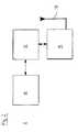
- the imaging system 1 shown in figure 1comprises a hand held ultrasound probe 2 as an imaging probe connected via a cable 3 with a processing unit 4.
- the processing unit 4drives the ultrasound probe 2, i.e. it sends electrical signals to the ultrasound probe 2 to generate ultrasound pulses and interprets the raw data received from the ultrasound probe 2 to assemble it into an image of the patients tissue scanned with the ultrasound probe 2.
- a battery operated magnetometric detector 5is, by means of a Velcro fastener (not shown) attached to the ultrasound probe 2.
- Positioning elementsare provided on the magnetometric detector 5 to ensure that whenever it is attached anew to the ultrasound probe 2 it is always attached in the same well-defined position and orientation.
- the magnetometric detector 5comprises magnetometers 14, 15 (not shown in figure 1 ) and is wirelessly or by other means connected with a base unit 6 in a bi-directional manner (indicated by the flash symbol 7).
- both the magnetometric detector 2 and the base 6 unitare provided with wireless transceivers.
- the transceiversmay for example employ the BluetoothTM standard or a standard from the WiFi (IEEE 802.11) family of standards.
- the base unit 6receives the normalized results of the measurements of the magnetometric detector 2 and from this calculates the position or, in some embodiments the position and orientation of a magnetic medical cannula 8.
- additional informationsuch as the state of charge of the magnetometric detector's 5 battery is transmitted from the magnetometric detector 5 to the base unit 6.
- configuration informationis transmitted from the base unit 6 to the magnetometric detector 5.
- the base unit 6forwards the result of its calculation, i.e. the position or in some embodiments the position and orientation information, to the processing unit 4.
- the base unit 6may for example be connected with the processing unit 4 via a standardized serial connector such as a USBTM (Universal Serial Bus) connector, a FireWireTM (also referred to as iLinkTM or IEEE1394) connector or a ThunderboltTM (also referred to as Light PeakTM) connector.
- a standardized serial connectorsuch as a USBTM (Universal Serial Bus) connector, a FireWireTM (also referred to as iLinkTM or IEEE1394) connector or a ThunderboltTM (also referred to as Light PeakTM) connector.
- the information received from the base unit 6 and the ultrasound imageare combined to generate on a display screen 9 of the processing unit 4 an image of the tissue of the patient in which the current position of the cannula 8 in the tissue is indicated.
- the base unit 6receives configuration information and/or a prior information about the position of the cannul
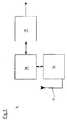
- the components of the magnetometric detector 5are shown schematically in greater detail in the block diagram of figure 2 .
- the magnetometric detector 5comprises an array 10 of two or more (e.g. four) magnetometers 14, 15 (not shown in figure 2 ) that is sampled by a microprocessor 11.
- the microprocessor 11normalizes the measurement results obtained from the magnetometer array 10 and forwards it to a transceiver 12 with an antenna 13 which, in turn transmits the information to the base unit 6.
- the magnetometric detector 5is provided with a multiplexer rather than with a microprocessor 11 and the normalization is performed by a processor 18 in the base unit 6.
- Each magnetometer 14, 15 in the array 10 of magnetometers 14, 15measures the components a k u , a k v , a k w (k indicating the respective magnetometer) of the magnetic field at the position of the respective magnetometer 14, 15 in three linearly independent directions.
- the base station 6 shown schematically in greater detail in figure 3receives the normalised positional information from the magnetometric detector 5 through its receiver 16 with antenna 17 and forwards the information to a processor 18. There, the normalized results of the measurements are combined to derive the position (or position and orientation) of the cannula 8.
- the values b kare fit to a model of the combined magnetic field originating from the magnetic cannula 8 and the terrestrial magnetic field.
- the parameters pare obtained at which the deviation of the components of the magnetic field according to the model from the components actually measured ⁇ k b k ⁇ c k p 2
- Suitable minimization techniquesare for example gradient-descent algorithms as well as Levenberg-Marquardt approaches. Moreover, Kalman filter techniques or similar iterative means can be utilized to continuously perform such an optimization.
- the cannulais sufficiently rigid, i.e. it does bend only slightly, it can be approximated as a straight hollow cylinder.
- the magnetic field of such cylinderis equivalent to that of opposite magnetic charges (i.e. displaying opposite magnetic force) evenly distributed on the end surfaces of the cylinder, i.e. two circular rings at the opposite ends of the cannula, the rings having opposite magnetic charge.
- the chargescan further be approximated by two magnetic point charges at the opposite ends of the cannula.
- the cannulais always visualized as a line, the end of which corresponds to the cannula's tip. If the cannula 8 is within the probe's 2 imaging plane, it is, of a first colour (indicated as a full line 21 in the figures). If, on the other hand, the cannula 8 is outside the imaging plane, it is nevertheless shown, albeit in a different colour, the colour depending on whether the cannula 8 is in front of (colour indicated as a dashed line 22 in the figures) or behind the imaging plane (colour indicated as a dotted line 23 in the figures).
- Figure 4ashows the situation when the cannula 8 cuts through the imaging plane.
- the section of the cannula 8 behind the imaging planeis shown in a different colour than the part of the cannula 8 that cuts through the plane which again has a different colour to the part of the cannula 8 that is in front of the imaging plane.
- the situation in figure 4cdiffers from that in figure 4a only in that the cannula 8 cuts through the plane in a different angle.
- the sections of the cannula 8 outside the imaging planeare shown on the display as their projections vertically onto the imaging plane.
- the whole expected needle trackis shown on the image display, as described above.
- the actual position of the needleis indicated either by a different colour or line style (bold/hatched/etc) of the needle track.
- the point of cutting through the imaging planemight be indicated by a special graph for example, either the circle shown in Figure 4a or a rectangle.
- the form or appearance of the graphmight change to indicate the probability of the needle piercing the plane at that point, i.e. instead a circle a general ellipse might be used to indicate the target area.
- FIG. 5An alternative embodiment of the magnetometric detector is shown in figures 5 and 6 .
- This magnetometric detectorin a first variant of the embodiment only comprises a set 5 two magnetometers 14, 15.
- one or more further setsare provided in further locations on the ultrasound probe 2. It is possible to derive whether the cannula 8 is located within the imaging plane 24, in front of 25 the imaging plane or behind 26 the imaging plane 24.
- the magnetometersare arranged along a line parallel to the probe's longitudinal axis. The normalized measurement results of the first magnetometer 14 are subtracted from those of the second magnetometer 15, thereby effectively cancelling out the terrestrial magnetic field.
- the differenceis essentially pointing into the direction of the needle tip, because the other field component, caused by the end of the needle, is rapidly decaying in distance from the sensor arrangement.
- the sensoressentially "sees” only the needle tip. A relative distance can be inferred through the magnitude of the measured difference field.
- the magnetometers 14,15are arranged perpendicular to the probe's longitudinal axis.
- the difference obtainedessentially is the gradient of the magnetic field generated by the magnetic cannula 8.
- a relative distance of the cannula from the sensorcan be elucidated.
- the direction of the gradientit can be elucidated if the cannula 8 is in front of 25 or behind 26 or directly on the imaging plane 24.
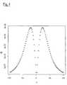
- Figure 7shows the absolute gradient field strength G (in arbitrary units) of a cannula 8 that extends in parallel to the imaging plane 24 but at a distance Y (in arbitrary units) from this plane 24.
- the gradient field strength Ghas a minimum if the distance Y equals 0, that is if the cannula 8 is in the imaging plane 24. If, on the other hand, the gradient field strength G is above a certain threshold, the cannula 8 can be assumed to be outside the imaging plane 24. In this case, the direction of the gradient field indicates whether the cannula 8 is in front of 25 or behind 26 the imaging plane 24 (this is not shown in figure 7 as the figure only shows the absolute value of the field).
- figure 8shows an apparatus 27 for magnetizing cannulae 8 according to the invention.
- a reservoir(not shown) which can hold a number of cannulae 8, each cannula 8 enclosed in a separate sterile film packaging 28.
- the apparatus 27moreover comprises a round opening 29 through which individual cannulae 8 with their film packaging 28 can removed from the reservoir.
- the openingis surrounded by a ring-shaped solenoid electromagnet (not shown).
- the electromagnetis powered by a power supply (not shown) attached to the apparatus.
- a switch on the power supplycan electrify the electromagnet and thus turn on an electromagnetic field.
- Appropriate modulation of the electromagnet's currentwill allow coded magnetization as the needle is with-drawn from the reservoir.
- the openingis one side of a hollow cylinder composed of separate magnetizing coils which allow imprinting a magnetic code onto the medical device in one step.
- the cannula's 8 magnetic moment and lengthit is, still enclosed in the transparent sterile film packaging 28, placed on a line-shaped marking 30 on the apparatus 27.
- the ultrasound probe 2 within the attached magnetometric detector 5is placed on another, box-shaped, marking 31 on the apparatus 27.
- the magnetic moment and the length of the cannulacan easily be derived from the measurements of the magnetometers 14, 15 after normalization. These values can then be used during the medical procedure to facilitate deriving the position and orientation of the cannula 8 from the measurements of the magnetometers by means of the above-described model.
Landscapes
- Health & Medical Sciences (AREA)
- Life Sciences & Earth Sciences (AREA)
- Physics & Mathematics (AREA)
- Engineering & Computer Science (AREA)
- Surgery (AREA)
- General Health & Medical Sciences (AREA)
- Veterinary Medicine (AREA)
- Biomedical Technology (AREA)
- Heart & Thoracic Surgery (AREA)
- Medical Informatics (AREA)
- Molecular Biology (AREA)
- Animal Behavior & Ethology (AREA)
- Public Health (AREA)
- Pathology (AREA)
- Biophysics (AREA)
- Nuclear Medicine, Radiotherapy & Molecular Imaging (AREA)
- General Physics & Mathematics (AREA)
- Radiology & Medical Imaging (AREA)
- Condensed Matter Physics & Semiconductors (AREA)
- Power Engineering (AREA)
- Human Computer Interaction (AREA)
- Robotics (AREA)
- Electromagnetism (AREA)
- Gynecology & Obstetrics (AREA)
- Chemical & Material Sciences (AREA)
- Analytical Chemistry (AREA)
- Biochemistry (AREA)
- Immunology (AREA)
- Ultra Sonic Daignosis Equipment (AREA)
- Measurement Of Length, Angles, Or The Like Using Electric Or Magnetic Means (AREA)
- Magnetic Resonance Imaging Apparatus (AREA)
- Investigating Or Analyzing Materials By The Use Of Magnetic Means (AREA)
Description
- The invention relates to methods of obtaining information about the position and/or orientation of a magnetic component relatively to a magnetic detector. It further relates to systems of an imaging probe for imaging at least part of the tissue of a patient and a magnetic detector for detecting the position and/or orientation of the magnetic component relatively to the magnetometric detector. It moreover relates to a medical device at least a portion of which is insertable into the tissue of the patient, the medical device comprising a magnetic component, and to a method of obtaining position and/or orientation information about at least a part of a medical device. Finally, the invention relates to an apparatus for magnetizing an elongate medical device.
- In numerous medical procedures that involve the insertion of a medical device into a patient's tissue, e.g. minimally invasive procedures and local anesthesia, it can be of great advantage for the physician to be informed of the exact position of the medical device in the patient's tissue. For example, to introduce regional anesthesia, including peripheral nerve blocks for surgical anesthesia or postoperative analgesia, a needle can be guided to the region of interest with the help of ultrasound imaging. It has proven challenging, however, to precisely detect the needle's end point in the ultrasound image.
- Northern Digital Inc., Ontario, Canada (www.ndigital.com) offers an electromagnetic detection system under the trade name "Aurora". The system comprises a field generator for creating an electromagnetic field and various types of sensor coils that react to the field produced by the generator. One or more of the sensor coils can be embedded into a medical instrument such as a biopsy needle, a catheter or a flexible endoscope for measuring in real time the position of the instrument's tip or, if several coils are embedded, the shape of the instrument. The various types of sensor coils available differ in shape and size and can detect their position relatively to the generator's electromagnetic field in three-dimensional space and their orientation in two or three dimensions. Wires connect the sensor coils with a sensor interface unit that transmits the coils' data to a system control unit. The system control unit collects the information obtained from the sensor coils and calculates their position and orientation.
- In "Evaluation of a miniature electromagnetic position tracker", Mat. Phys. (2002), 29 (1), 2205 ff., Hummelet al. have studied the effects of the presence of an ultrasound scan head on the accuracy of the "Aurora" electromagnetic tracking system measurement results.
Placidi, G. et al. in "Review of Patents about Magnetic Localization Systems for in vivo Catheterizations", Rec. Pat. Biomed. Eng. (2009), 2, 58 ff., distinguish between systems where the magnetic field is located outside the patient's body ("extra-body generated magnetic field" as in the "Aurora" system) and systems where the magnetic field is generated by a permanent magnet located inside the patient's body ("intra-body permanent magnet"). A system is discussed that can detect the location in three dimensions and the orientation in two dimensions of a permanent magnet that is permanently fixed to an intra-body medical device. Each measurement involves at least two spatially separated three-axis magnetic sensors in order to measure x -, y-and z- components of the magnetic field produced by the permanent magnet in at least two spatial positions. Six magnetic sensors are arranged in a circle surrounding the patient in order to ensure that each part of the patient's body is covered by at least two of the sensors. Before use, the system is calibrated to take into account the terrestrial magnetic field. In the calibration step, in the absence of the permanent magnet, the terrestrial magnetic field is measured and then subtracted from each subsequent measurement. From the remainder, the position of the magnet is calculated. It is considered a disadvantage of the system that it cannot be moved once calibrated. - Yet, the patent
US 6 263 230 B1 , on which the precharacterizing portion ofclaim 1 is based and which is cited in Placidi et al., supra, B1 describes a "continuous automatic recalibration" scheme with which a detector can be moved after the initial calibration, even though not simultaneously with the magnet. The magnetic detector system is attached to a fluoroscopic head in a known spatial relationship to detect the position of a permanent magnet of an indwelling medical device and the magnet's field is approximated as a dipole field. In order to compensate for the terrestrial magnetic field as well as localized perturbations associated with this field, an initial calibration is performed
before the magnet is introduced into the patient. For each magnetic sensor of the detector system an offset value is determined. Later, when the magnet has been introduced into the patient, the offset values are subtracted from the readings of the magnetic sensors, thus compensating for the terrestrial magnetic field and its localized perturbations. Moreover, the "continuous automatic recalibration" scheme allows compensating for the localized perturbations of the terrestrial magnetic field even if the detector system is moved: According to this scheme, the detector is moved while the magnet remains stationary at its position that is known from the previous measurement. The exact positional change of the detector is tracked by a digitizing arm and from this the magnetic field at the detector's new location due to the magnet is calculated. The result is subtracted from the field actually measured by the detector and the remainder is considered the contribution of the terrestrial magnetic field at the new location. The process can be repeated as the detector is moved to yet another location. US 6 216 029 B1 discloses an apparatus for ultrasound free-hand directing of a needle. Both an ultrasound probe and the needle or a needle guide are provided with orientation sensors for sensing the position of the probe and the needle with respect to a reference. The orientation sensors each may comprise three transponders in triangular alignment. The transponders preferably are electro-optical sensors which operate with infrared or visible light. Alternatively, the system comprises a magnetic transmitter and magnetic receivers attached to an ultrasound probe and the needle or needle guide. On a displays screen, the ultrasound image of a target area is shown. Moreover, the needle is shown as a distinctly coloured line, even if the needle is outside the ultrasound image. In addition or alternatively, a trajectory of the needle is displayed.- Similarly,
US 6 733 468 B1 discloses a diagnostic medical ultrasound system in which both an ultrasound probe and an invasive medical device, e.g. a cannula, have location sensors attached to them for sensing their position and/or orientation. From the positions of the needle and the probe the relative position of the needle with respect to the probe's imaging plan is determined. From this, a projected and an actual trajectory of the invasive medical device are calculated and superimposed on the ultrasound image. US-A1-2010/0249576 discloses a system in which a magnet is attached to an anatomical feature or to a swallowable capsule and tracked magnetically using a magnetic detector which is also fitted with an accelerometer to give the position of the detector.US-A1-2009/0156926 discloses the use of a magnetic sensor attached to the chest of a patient to detect the approach of a catheter tip fitted with a magnet. The patient's anatomy is also scanned by ultrasound and a display can display either the ultrasound image or the magnet track.- It is an objective of the present invention to provide an improved method of obtaining information about the position and/or orientation of a magnetic component relatively to a magnetometric detector.
- In the following, the present invention is described with reference to the claims. Note that the reference numbers in all claims have no limiting effect but only serve the purpose of improving readability.
- According to one aspect of the invention, the problem is solved by providing a method with the features of
claim 1. Thus, according to the invention, the position and/or orientation of the magnetic component relatively to the magnetometric detector is obtained directly. Advantageously, because the effect of the secondary magnetic field is computationally eliminated by combining the results of the at least two simultaneous measurements, the initial calibration step that is for example used in the method described inUS 6 263 230 B1 for obtaining offset values to compensate for the terrestrial magnetic field is no longer required. Also, the "continues automatic rccalibration" procedure disclosed therein, which relies on a digitizing arm to measure the detector's positional change and moreover requires that the magnetic components remains stationary while the detector is moved, can be avoided. Rather, the position and/or orientation of the magnetic component can be derived even if the magnetometric detector and the magnetic component are moved simultaneously. This is of considerable benefit, in particular when the magnetometric detector is attached to a hand held probe such as an ultrasound probe for ultrasound-assisted medical procedures to track the position of a medical device relatively to the image created by the probe of the tissue of the patient. In such cases, it is almost impossible for the physician to keep the probe stationary while the medical device is moved. Moreover, as the digitizing arm ofUS 6 263 230 B1US 6 263 230 B1e.g. US 6 216 029 B1 andUS 6 733 468 B1US 6 216 029 B1US 6 733 468 B1 - Also advantageously, by combing the results of the two measurements taken essentially simultaneously to obtain the position and/or orientation of the magnetic component, procedures can be eliminated that rely on an oscillating magnetic field of the magnetic component, e.g. the methods disclosed in Placidi, G.et aL, supra, in relation to extra-body generated magnetic fields, in order to compensate for the terrestrial magnetic field.
- In the context of the present invention, a "magnetometric detector" is a device that can obtain quantitative information about the magnetic field to which it is exposed, such as the absolute value, the direction and/or the gradient of the magnetic field. The magnetometric detector may contain one or more magnetometers. The expression "spatially associated" in relation to the positions at which the measurements take place and the magnetometric detector means that the positions move in synchrony with the detector (and consequently with each other) so that from the location and orientation of the positions that of the detector can be derived.
- The "secondary magnetic field" will in general comprise the terrestrial magnetic field. In addition, it might comprise distortions in the terrestrial magnetic field or other magnetic field, e.g. created by apparatus in the vicinity of the magnetometric detector. The preferred secondary magnetic field is essentially homogeneous within the space in which the magnetometric detector moves when used.
- A "magnetic component" is an entity that creates its own magnetic field. Due to its magnetic property the magnetic component can provide the magnetometric detector with information about its position and/or orientation.
- "Information about the position" of the magnetic component refers to the position in at least one spatial dimension, more preferably in two, more preferably in three dimensions.
Similarly, the "information about the orientation" of the magnetic component refers to the orientation in at least one spatial dimension, more preferably in two, more preferably in three dimensions. The obtained information preferably is the position and/or orientation of the magnetic component within a certain resolution. Yet, merely the information as to whether the magnetic component is in an imaging plane of the imaging probe or not would already constitute position information within the scope of the present invention. Moreover, information of whether the magnetic component is in front of or behind the imaging plane constitutes position information. - The problem according to the invention is also solved by providing a method with the features of claim 3. The method according to claim 3 can advantageously exploit the fact that from the measurement of the inertial measurement unit the orientation or even both the orientation and position of the magnetometric detector can be derived. From the result, the orientation or orientation and strength, respectively, of the secondary magnetic field, preferably the terrestrial magnetic field, relatively to the detector can be derived. For this purpose, preferably, in an initial calibration step the orientation or strength and orientation of the secondary magnetic field relatively to the magnetometric detector are measured in the absence of the magnetic component. By tracking the orientation changes of the magnetometric device from the initial calibration position one can calculate the components of a secondary magnetic field which is approximately stationary in space and time.
- Within the context of the present invention, an "inertial measurement unit" is a unit that comprises a gyroscope and/or an accelerometer, preferably both. Similarly to the solution of
claim 1, advantageously, for providing the desired information about the position and/or orientation of a magnetic component no means as a reference other than the magnetic component is required. - A "hand held probe" is a probe that the use is intended for the user to be held in the desired position by hand. In particular, in a hand held probe, technical means such as a support arm, a runner or a wire are lacking that would hold the probe in position should the user remove his or her hand. The preferred hand held probe comprises a handle.
- The medical device and the method of obtaining position and/or orientation information about at least a part of a medical device exploit the inventors' finding that many medical devices comprise functional components, e.g. a cannula or a metal rod, which can be magnetized in order to render the medical device detectable by a magnetometric detector. The functional component of the medical device can therefore simply by means of magnetization be assigned to an additional purpose beyond its original function in the medical device.
- In the context of the present invention, a "functional component" of the medical device is a component that in addition to providing the magnetometric detector with position and/or orientation information also contributes to the functioning of the medical device, i.e. it contributes to the medical device serving its purpose as a medical device. In this regard, forwarding position and/or orientation information to the magnetometric detector is not considered a function of the medical device. The function may e.g. be the transport of a fluid into or out of the patient's tissue if the medical device is a catheter or a cannula, or the function may be an electrosurgical treatment if the medical device is an electrosurgical instrument.
- The preferred magnetic component is an "essential" component of the medical device. In this context, "essential" means that the medical device cannot fulfil its purpose when the magnetic component is removed. Alternatively, the magnetic component is not essential but nevertheless beneficial. It may for example improve the functionality, the handling or other properties of the medical device beyond providing orientation and/or position information to the magnetometric detector.
- An apparatus can be used to magnetize the elongate medical device, e.g. a cannula, just before a medical procedure is performed. Due to the apparatus comprising both a reservoir for keeping the elongate medical device and a magnetizer, cannula can easily be magnetized by e.g. a physician in order to turn them into magnetic components for use in the methods, with the system and in the medical device according to the invention.
- While for better understanding of the fundamental concepts of the invention throughout the present description and the claims reference is made only to one magnetic component, the invention in all its aspects of course also encompasses embodiments in which in addition further magnetic components are present. As is readily apparent to those skilled in the art, the methods, apparatus and systems according to the invention can equally be applied to multiple magnetic components instead of only one magnetic component.
- Preferred features of the invention which may be applied alone or in combination are discussed in the following as well as in the dependent claims.
- Preferably, the strength and/or orientation of the magnetic field as measured at one or more of the positions spatially associated with the magnetometric detector is used as a direct estimate of the strength and/or orientation of the secondary magnetic field, i.e. the (possibly distorted) terrestrial magnetic field. For this purpose, preferably, these position or positions are separated far enough away from the magnetic component to ensure that the measurement at this/these position(s) is sufficiently unaffected by the magnetic component's magnetic field to directly provide an estimate of the strength and/or orientation of the secondary magnetic field. Therefore, if the magnetometric detector is integral with or attachable to a imaging probe, e.g. an ultrasound imaging probe, as discussed further below, the means (e.g. magnetometers) of the magnetometric detector for measuring the strength and/or orientation of the secondary magnetic field according to the present embodiment of the invention is/are sufficiently remote from the part of the imaging probe that is closest to the patient to ensure that the magnetometer(s) is/are essentially unaffected by the magnetic field of the magnetic component introduced into the patient's tissue.
- In the context of this embodiment "direct estimate" means that the measurements at the position or positions are sufficient to estimate, within the required accuracy, the strength and/or orientation of the secondary magnetic field.
- Advantageously, the magnetic field as measured according to the above preferred embodiment of the present invention can simply be subtracted from the result of the measurement at one or more other position(s) in order to obtain for each of these other measurements the magnetic field of the magnetic component only. This can then be used to derive the position and/or orientation of the magnetic component.
- Preferably, the position and/or orientation of the magnetic component is computed by fitting a model of the magnetic field due to the magnetic component to the actual magnetic field of the magnetic component as obtained from the measurements at the positions affected by magnetic component's field after the secondary magnetic field has been subtracted. Thus, position and/or orientation of the magnetic component are the unknown parameters in the model fitting procedure.
- In an alternative embodiment of the inventions, a model that comprises the secondary magnetic field, preferably a homogenous magnetic field representing the terrestrial magnetic field, is a further unknown parameter in a model, and the model is fit by a suitable algorithm to the results of the measurements at the positions in order to derive the unknown parameters, i.e. the position and/or orientation of the magnetic components and, if of interest, also the strength and/or orientation of the secondary magnetic field. This method is preferably employed if all positions of the magnetometric detector at which the strength and/or orientation of the magnetic field is measured are considered to be potentially affected by secondary magnetic field to a degree that none of them can directly provide an estimate of the strength and/or orientation of the secondary magnetic field.
- In a variation of the above method, the effect of the secondary magnetic field on the results of the measurements at the positions is first cancelled out by determining differential values of the measurements at different positions. For example, after normalization (as discussed below), the average of the strength and/or orientation of the magnetic field determined at the various positions can be subtracted from the strength and/or orientation of the magnetic field at each individual position. Hence, in effect the magnetometers function as gradiometers. These differential values can then be fit to a model that utilizes differentials or other functional derivatives of the original magnetic field.
- Moreover, preferably, from the measurements, the change in orientation and/or position of the magnetometric detector due to a movement of the magnetometric detector is obtained. For example, the change in orientation and/or position of the magnetometric detector can be obtained from the orientation of the detector relatively to the terrestrial magnetic field as computed from combining the results of the measurements at two or more positions of the magnetometric detector. Also, the orientation and position of the magnetometric detector can be derived from the measurements of an inertial measurement unit. If the magnetometric detector is attached to an imaging probe, this information can be used, for example, to combine the images acquired by the imaging probe at different positions and/or in different orientations into a three-dimensional map or a panoramic map. In particular, this may facilitate three-dimensional mapping of extended volumes. Thus, the inertial measurement unit, in particular the accelerometer, on one hand and the measurement of the strength and/or orientation of the magnetic field for estimating the secondary magnetic field on the other hand can substitute each other. However, the invention also comprises embodiments in which both of these means are provided. In particular, the results of both means can be combined, e.g. averaged, to improve accuracy.
- In the magnetometric detector the strength and/or orientation of the magnetic field preferably is measured, in at least two positions, more preferably at least three, more preferably at least four positions spatially associated with the magnetometric detector, the positions being distanced from each other. The measurements may be combined to derive the position and/or orientation of the magnetic component. They may be moreover combined to computationally eliminate the effect of the secondary magnetic field.
- Preferably, the magnetic field in at least two positions, more preferably at least three, more preferably at each of the positions is measured by a magnetometer of the magnetometric detector, each magnetometer being located at the respective position. Preferably, at the first position, more preferably also at the second position, more preferably also at the third position, more preferably at all positions of the magnetometric detector the components of the magnetic field in at least two linearly independent spatial directions, more preferably in all three linearly independent spatial directions are measured.
- In a preferred embodiment of the invention, the results of the measurements are transmitted to a base unit for processing, the preferred base unit being separate from the magnetometric detector. In this context, "separate" means that the base unit and the magnetometric detector do not move in synchrony with each other; in other words, they are not spatially associated. Rather, the magnetometric detector can move independently of the base unit. In particular, the base unit can remain stationary while the magnetometric detector (preferably attached to the imaging probe as discussed above) is moved. The transmission between the magnetometric detector and the base unit can be realised, for example, by a flexible cable or by a wireless connection. It is an advantage of the wireless connection that the magnetometric detector can be attached to a conventional imaging probe without requiring another cable in addition to the probe cable.
- It is an achievable advantage of this embodiment of the invention that a large part or even all of the computation required to derive from the results of the measurements the position and/or orientation of the magnetic component can be performed in the base unit. This is of benefit in view of the fact that the computational means required for eliminating the effect of the secondary magnetic field and deriving the position and/or orientation of the magnetic component can be too demanding for a microprocessor small enough to be easily attached to the imaging probe. Therefore, by shifting part or all of the computation to the base unit where sufficient processing power can more easily be provided, the magnetometric detector can be kept small and light.
- In another embodiment, the base unit is merged with the imaging system, with the information from the magnetometers delivered through the probes cable.
- A preferred magnetometric detector comprises several magnetometers, possibly along with an inertial measurement unit, and interface circuitry which might be a multiplexer or a microprocessor. The interface circuitry enables to pass the signals of multiple probes through a single cable or wireless link. It samples the magnetometers (and the inertial measurement unit if present) and possibly monitors other information such as a state of charge of a battery of the magnetometric detector. By means of a transmitter of the magnetometric detector, this information is then transmitted to a receiver of the base unit.
- In a preferred embodiment of the invention the magnetometric detector moreover receives information from the base unit. Thus, preferably, two-way communication is possible between the magnetometric detector and the base unit. The return channel from the base unit to the magnetometric detector can for example be used to reconfigure the magnetometers or the inertial measurement unit remotely from the base unit. For example, the working range of the magnetometers can be adapted to the strength of the magnetic components' magnetic field, in particular to avoid overflows in the measurement process.
- For transmission, the magnetometric detector and the base unit are functionally connected with each other. The term "functionally connected" encompasses both a direct connection and an indirect connection through one or more intermediate components, which intermediate components may be hardware and/or software components. Preferably, the transmission between the magnetometric detector and the base unit is encoded in a way to prevent eavesdropping, e.g. by means of asymmetrical encryption. Moreover, preferably measures are taken to prevent interference in the case several systems comprising a magnetometric detector and a base unit are operated in close vicinity.
- Preferably, in a calibration step, the magnetometers are calibrated with regard to gain, offset and orientation so that in a homogeneous magnetic field they all yield essentially identical measurements. Thereby it is ensured that all magnetometers measure equal values when exposed to a homogeneous field. For example, a magnetometer rotated in the homogeneous terrestrial magnetic field should, depending on the orientation of the magnetometer, measure varying strengths of the components of the magnetic field in the three linearly independent directions. The total strength of the field, however, should remain constant regardless of the magnetometer's orientation. Yet, in magnetometers available on the market, gains and offsets differ in each of the three directions. Moreover, the directions oftentimes are not orthogonal to each other. As described for example in
US 7 275 008 B2 for a single sensor, if a magnetometer is rotated in a homogeneous and constant magnetic field, the measurements will yield a tilted 3-dimensional ellipsoid. Because the measured field is constant, however, the normalized measurements should lie on a sphere. Preferably, an offset valueβ and a gain matrixM are introduced to transform the ellipsoid into a sphere. - With a set of sensors, additional steps need to be taken to assure that the measurements of different sensors are identical with each other. To correct for this, preferably, set of a gain normalisation matricesMk and a normalisation offset vectorsβk for each position k are determined which transform the magnetometer's raw resultsak into a normalized resultbk:

- Such a set of gain matricesMk can be obtained by known procedures, for example the iterative calibration scheme described inDorveaux et. al., "On-the-field Calibration of an Array of Sensors", 2010 American Control Conference, Baltimore 2010.
- By virtue of the defined transformation,bk provides the strength of the component of the magnetic field in three orthogonal spatial directions with equal gain. Moreover, it is ensured that these directions are the same for all magnetometers in the magnetometric detector. As a result, in any homogeneous magnetic field, all magnetometers yield essentially identical values.
- The normalisation informationMk andβk for each magnetometer as obtained in the calibration step can be stored either in the magnetometric detector itself or in the base unit. Storing the information in the magnetometric detector is preferred as this allows easy exchange of the magnetometric detector without the need to update the information in the base unit. Thus, in a preferred embodiment of the invention, the magnetometers of the magnetometric device are sampled and their results are normalised in the magnetometric detector. This information, possibly together with other relevant information, is transmitted to the base unit for further analysis.
- In another embodiment of the invention, the transformation can be another, more general non-linear transformationbk = F(ak).
- In addition to the above calibration method, another calibration method is applied which employs an inhomogeneous magnetic field to obtain the relative spatial locations of the magnetometric detector's magnetometers. While standard calibration methods utilize a homogenous magnetic field to (a) align the measurement axis of the magnetometers orthogonally, (b) cancel the offset values and (c) adjust to equal gain, it is of further advantage to the described systems that also the precise relative spatial locations of the magnetometers are available. This can be achieved by an additional calibration step in which the magnetometric detector is subjected to a known inhomogeneous magnetic field. Preferably, comparing the obtained measurements at the various positions to the expected field strengths and/or orientations in the assumed locations, and correcting the assumed locations until real measurements and expected measurements are in agreement, allows for the exact calibration of the spatial positions of the sensor.
- In a variation of the latter calibration method, an unknown rather than a known homogenous field is used. The magnetometers are swept through the unknown magnetic field at varying positions, with a fixed orientation. With one of the magnetometers supplying a reference track, the positions of the other magnetometers are adaptively varied in such a way that their measurements align with the measurements of the reference unit. This can be achieved for example by a feedback loop realizing a mechano-magnetic-electronical gradient-descent algorithm. The tracks used in this inhomogeneous field calibration can also be composed of just a single point in space.
- Preferably, the magnetometric detector is integral with or removably attachable to an imaging probe for imaging at least part of the tissue of a patient. "Integral" means that the magnetometric detector is permanently fixed to the imaging probe in a way that, if the imaging probe is used as intended, the magnetometric detector cannot be removed from the imaging probe. It may, for example, be located inside a housing of the imaging probe. The magnetometric detector may even be joined with the imaging probe to a degree that for the purpose of service or repair it cannot be separated from the imaging probe without destroying the imaging probe. Yet, the term "integral" also encompasses embodiments in which the magnetometric detector can be removed from the imaging probe for the purpose of repair or maintenance. Within the context of the present invention, "removably attached" means that one part can be removed from the other part to which it is attached by a user if the device is used as intended. Thus, for example, while the magnetometric detector remains attached to the imaging probe to be spatially associated to it during a medical procedure, after the medical procedure has been finished, the detector can be removed from the probe to be attached to another imaging probe for another medical procedure. Preferably, for the purpose of removable attachment, at least one of the magnetometric detector and the imaging probe, preferably both are provided with one or more fasteners. Preferably, the magnetometric detector and the imaging probe are attached to each other in a way that ensures that during use in a medical procedure they are in a fixed position relatively to each other.
- The preferred imaging probe is an ultrasound imaging probe. Such an ultrasound imaging probe preferably includes an array of ultrasound transducers. With the aid of the transducers, ultrasound energy, preferably in the form of ultrasound pulses, is transmitted into a region of the patient's tissue to be examined. Subsequently, reflected ultrasound energy returning from that region is received and registered by the same or other transducers. Yet, the present invention may also be used with other types of imaging probes, for example impedance imaging probes, including probes of the kind disclosed in
US 7 865 236 B2 to Nervonix Inc. - Other suitable imaging probes include IR sensors or cameras able to measure blood flow and/or other scanning devices.
- Moreover, preferably, a processing unit is provided. The position-related information produced by the magnetometric detector and the image information produced by the imaging probe preferably is transmitted from the magnetometric detector and the imaging probe, respectively, to the processing unit (the position-related information preferably via the base unit as discussed above). The information may then be combined in the processing unit to generate an image of the tissue of the patient in which image the position of at least a part of a medical device is indicated based on the position and/or orientation information obtained from the magnetometric detector. The preferred processing unit comprises a display device for displaying the image. In this context, "position-related information" may for example be the raw data obtained by the magnetometers, the calibrated data or actual positions and orientations computed as discussed above. Similarly, "image data" may be raw data obtained by the imaging probe or raw data that has been further processed.
- In a preferred embodiment of the invention, the processing unit drives the imaging probe and interprets the raw data received from the imaging probe, e.g. the ultrasound probe. Moreover, preferably, a cable or a bundle of cables is provided to connect the imaging probe with the processing unit. If the imaging probe is an ultrasound probe, the processing unit preferably comprises a driver circuitry to send precisely timed electrical signals to the transducers of the imaging probe in order to generate ultrasound pulses. As part of the ultrasound pulses is reflected from the region to be examined and returns to the ultrasound probe, the received ultrasound energy is converted into electrical signals which are then forwarded to the processing unit. The processing unit amplifies and processes the signals to generate an image of the examined region of the patient's tissue.
- As the medical device's positional information is obtained by detecting the position of the device's magnetic component, the part of the medical device, the position of which is indicated, preferably will either be the magnetic component or another component of the medical device, the position of which relatively to the magnetic component is known. In one embodiment of the invention, only a section of the magnetic components is shown, for example the most distal section, such as the distal tip of a cannula.
- For transmission of the information from the magnetometric detector and the imaging probe (preferably via the base unit) to the processing unit, the former components are functionally connected with the processing unit. Preferably, the processing unit is further functionally connected to the magnetometric detector (preferably via the base unit) to receive information from the base unit. This way, relevant information may be transmitted from the processing unit or the magnetometric detector to facilitate the computation that takes place therein.
- It can be most useful if the image generating processing unit is connected in a bi-directional way. Information obtained by processing the recorded image, preferably in the processing unit, can be transferred to the base unit to facilitate the estimation of the needle position, and vice versa. For example, a Hough-Transformation on a raw ultrasound image might detect a faint image of a needle; this localization information from the ultrasound image can be applied as constraint to the optimization step deriving the same needle position from the magnetometer data. Of course, needle detection algorithms operating directly on the image can as well be stabilized through the information about needle positions coming from the base unit.
- Preferably, in the image it is indicated whether the medical device or part of the medical device is located inside or outside a pre-determined spatial plane. Preferably, on the display the image of the patient's tissue in a certain plane is displayed which is identical to the predetermined spatial plane. The displayed plane may for example be determined by the position and/or orientation of the imaging probe. For example, if the imaging probe is an ultrasound imaging probe that operates in a 2D-mode, the displayed plane is the probe's imaging plane. Preferably, if multiple sections of a medical device are displayed, it is indicated which of the sections is located in the spatial plane, which is located on one side of the spatial plane and which is located on the other side of the spatial plane. For example, the imaging plane of the imaging probe can be associated with one colour, one side of the imaging probe with another colour and the other side with a third colour. Alternatively, or in addition, a trajectory of a part of the magnetic component or medical device may be displayed, for example as disclosed in
US 6 733 458 B1 - The magnetic component preferably is integral with the remaining medical device. Alternatively, it may be a replaceable part, for example the cannula of a syringe.
- The function of the medical device preferably does not depend on the magnetic component being magnetic. In other words, even if the component were not magnetic, the medical device would still perform its purpose. For example, a cannula is not required to be magnetic to serve its purpose of introducing a fluid into the tissue of the patient. This embodiment of the invention exploits the fact that certain components of medical devices, that in general are not magnetic, nevertheless have the potential to be magnetized and can then serve as magnetic components for providing positional and/or orientation information to a magnetometric detector.
- Alternatively, the magnetic component is a functional component and the function depends on the component being magnetic. In this case, the invention exploits the fact that the magnetic component in addition to serving its magnetism-related function in the medical device can also be used for providing position and/or orientation information.
- The inventors have found that magnetic components, in particular such of medical devices, can reliably be detected by conventional magnetometers available on the market. The magnetic component's magnetic field preferably is not alternating, i.e. it does not periodically change its sign or orientation. The preferred magnetic component's magnetic field is not varying in the sense that it keeps its orientation and/or absolute value with respect to the medical instrument tracked essentially constant during an examination, treatment or surgery. It has been found that such magnetized medical instruments keep their magnetization sufficiently constant during a typical medical procedure to be reliably detected by the magnetometric detector.
- The preferred magnetic component is at least partly a permanent magnet. Within the context of the present invention, a "permanent magnet" is an object that is magnetized, thereby creating its own persistent magnetic field due to magnetic remanence. Advantageously, since the magnet is permanent, no power source is required.
- While a permanent magnet is preferred, the invention also encompasses embodiments in which the magnetic component is a non-permanent magnet, e.g. an electromagnet, e.g. a solenoid to which an electric current can be applied to create the magnetic field. Moreover, in some embodiments of the invention part of the magnetic component may merely be magnetic due to magnetic induction from another part of the magnetic components, e.g. a permanent magnet-part of the component, while in other embodiments of the invention such induction does not play a role. The part of the magnetic component inducing the magnetic field in the other part must not necessarily be integral with the other part. Rather, the two parts may be separates. Nor must the two parts necessarily be adjacent to one another, but they can also be at a distance from each other. In fact, in general, the magnetic component can comprise not only one but several separate parts that can be distanced from each other, e.g. several permanent magnets arranged in a row in a medical device. Yet, a component of the medical device that is magnetic merely due to induction from outside the medical device, e.g. a coil of a radio-frequency antenna, does not create its own magnetic field and is therefore not considered a magnetic component within the context of the present invention.
- The magnetic components or part of the magnetic components may be a magnetic coating. Preferably, the coating is a permanently magnetic coating. For this purpose, it may for example comprise permanently magnetic particles, more preferably nanoparticles. A "nanoparticle" is a particle that in at least two spatial dimensions is equal to or smaller than 100 nm in size.
- In one embodiment of the invention, the magnetic component has an essentially uniform magnetization. In another embodiment, the magnetization is non-uniform in at least one dimension, i.e. the magnetic moment varies in magnitude and/ or direction as a function of the location on the magnetic component, thereby creating a one- or more-dimensional magnetic pattern, e.g. similar to the pattern of a conventional magnetic memory strip (at least one-dimensional) or disk (two-dimensional) as it is used for the storage of information e.g. on credit cards. In a preferred embodiment of the invention, a one-dimensional magnetic pattern may be recorded along the length of an elongate magnetic component, e.g. a cannula. Advantageously, such a pattern can be useful to identify the magnetic component and thus a device to which it is attached or which it is part of, e.g. the medical device, for documentation purposes. Also, by marking certain parts of the medical object with different magnetic codes, these parts can be distinguished. It is an achievable advantage of this embodiment of the invention that the position and/or orientation of the magnetic component can be better determined, as individual parts of the component can be identified and individually tracked with respect to their position and/or orientation. In particular, advantageously, a varying shape of the magnetic component, for example a needle bending under pressure, can be tracked. Moreover, a deformed magnetic component and/or the component's deformation or degree of deformation can be determined more easily.
- The preferred medical device is elongate, i.e. it is at least twice as long as it is wide. More preferably, at least the part of the medical device insertable into the patient's tissue is elongate.
- Preferably, at least the part of the medical device that is insertable into the tissue of the patient, more preferably the entire medical device, is tubular. Moreover, preferably the magnetic component is partially tubular. Alternatively, the part of the medical device that is insertable into the tissue of the patient or the medical component may have a non-tubular shape, for example that of a rod, e.g. if the medical device is an electrosurgical instrument. In a preferred embodiment of the invention, at least the part of the medical device that is insertable, more preferably the entire medical device is a cannula. Moreover, the cannula also constitutes the magnetic component. The preferred cannula has a bevelled end with which it is introduced into the patient's tissue.
- The invention can particularly favourably be used with such cannulae, as they bend easily and therefore the position of the inserted part of the cannula, in particular the cannula tip, cannot easily be determined from the position of a needle guide as disclosed in
US 6 216 029 - The invention can particularly advantageously be employed with cannula for regional anaesthesia. It may, however, also be employed with biopsy cannulae and catheters, e.g. catheters for regional anaesthesia. The preferred solid material of the cannula or catheter is permanently magnetized or the cannula or catheter is provided with a magnetic coating as described above. Alternatively or in addition, the cannula or catheter may be provided with a solenoid coil, preferably at its distal tip.
- The preferred apparatus for magnetizing an elongate medical device comprises a magnetization opening. The magnet preferably is located in the vicinity of the magnetization opening to magnetize the elongate medical device as it passes through the opening. Preferably the opening in the apparatus is an opening in the reservoir, through which opening the elongate medical device can be withdrawn from the reservoir so that when the elongate medical device is removed from the reservoir it is magnetized. Preferably, the elongate medical devices are kept in a sterile packaging different from the reservoir while they are stored in the reservoir. Preferably, they remain in this packaging while they are magnetized.
- The preferred elongate medical device is a cannula a rod or a needle. The preferred reservoir can hold more than one elongate medical device simultaneously.
- The magnet preferably is an electromagnet, e.g. a solenoid, more preferably a ring-shaped solenoid electromagnet. Alternatively, it may be a permanent magnet. The magnetizing device can be designed to uniformly magnetize the inserted medical device, or to record a magnetized pattern along the elongated medical object. This, for example, may be useful to identify the medical object used for documentation purposes as discussed above. Preferably, a variation of the magnetisation along the length of the elongate medical device can be achieved by varying the solenoid's magnetic field as the elongate medical device progresses through the magnetization opening. To control the variation of the magnetic field, the progress of the elongate medical device can for example be recorded by a measurement roll that is in contact with the elongate medical device when it passes through the magnetization opening. In another embodiment, the magnetization device is a hollow tube made up of separate segments of the magnet. By applying different currents to different sections of the tube, a magnetic pattern can be inscribed on the medical instrument.
- The apparatus may be further developed into a calibration tool by providing markings on the apparatus for alignment of the magnetometric detector and the elongate medical device. Preferably, for alignment the magnetometric detector is integral with or attached to the imaging probe and the imaging probe is aligned with the elongate medical device using the markings. Thus, the magnetometric detector is aligned with the medical device via the imaging probe.
- By virtue of the markings, the elongate medical device and the magnetometric detector can be put in a well-defined relative position. From this, based on the measurements of the magnetometric device specific parameters of the elongate medical device, most preferably its length and magnetic momentum can be measured for facilitating the later computation of the position and orientation of the cannula during the medical procedure. In fact, these parameters can greatly enhance fitting a model to the parameters measured by the magnetometers as described above.
- The invention is illustrated in greater detail with the aid of schematic drawings:
- Figure 1
- shows schematically an imaging system comprising an imaging probe, a magnetometric detector and a medical device according to the invention;
- Figure 2
- shows a block diagram of a magnetometric detector according to the invention;
- Figure 3
- shows a block diagram of a base unit according to the invention;
- Figure 4
- shows schematically three examples of images of the patient's tissue with the position and orientation of cannula superimposed according to a first embodiment of the invention;
- Figure 5
- shows schematically a magnetometric detector according to a second embodiment of the invention;
- Figure 6
- shows a system of an ultrasound imaging probe and the magnetometric detector according
figure 5 ; - Figure 7
- shows the absolute gradient field strength in the embodiment of
figures 5 and 6 as a function of the needle's distance from the imaging plane of the ultrasound imaging plane; and - Figure 8
- shows a magnetization apparatus for magnetizing a cannula according to the invention.
- The
imaging system 1 shown infigure 1 comprises a hand heldultrasound probe 2 as an imaging probe connected via a cable 3 with aprocessing unit 4. Theprocessing unit 4 drives theultrasound probe 2, i.e. it sends electrical signals to theultrasound probe 2 to generate ultrasound pulses and interprets the raw data received from theultrasound probe 2 to assemble it into an image of the patients tissue scanned with theultrasound probe 2. Moreover a battery operatedmagnetometric detector 5 is, by means of a Velcro fastener (not shown) attached to theultrasound probe 2. Positioning elements are provided on themagnetometric detector 5 to ensure that whenever it is attached anew to theultrasound probe 2 it is always attached in the same well-defined position and orientation. - The
magnetometric detector 5 comprisesmagnetometers 14, 15 (not shown infigure 1 ) and is wirelessly or by other means connected with abase unit 6 in a bi-directional manner (indicated by the flash symbol 7). For this, both themagnetometric detector 2 and thebase 6 unit are provided with wireless transceivers. The transceivers may for example employ the Bluetooth™ standard or a standard from the WiFi (IEEE 802.11) family of standards. Thebase unit 6 receives the normalized results of the measurements of themagnetometric detector 2 and from this calculates the position or, in some embodiments the position and orientation of a magneticmedical cannula 8. Along with the measurement results, additional information such as the state of charge of the magnetometric detector's 5 battery is transmitted from themagnetometric detector 5 to thebase unit 6. Moreover, configuration information is transmitted from thebase unit 6 to themagnetometric detector 5. - The
base unit 6 forwards the result of its calculation, i.e. the position or in some embodiments the position and orientation information, to theprocessing unit 4. For this purpose, thebase unit 6 may for example be connected with theprocessing unit 4 via a standardized serial connector such as a USB™ (Universal Serial Bus) connector, a FireWire™ (also referred to as iLink™ or IEEE1394) connector or a Thunderbolt™ (also referred to as Light Peak™) connector. In theprocessing unit 4, the information received from thebase unit 6 and the ultrasound image are combined to generate on adisplay screen 9 of theprocessing unit 4 an image of the tissue of the patient in which the current position of thecannula 8 in the tissue is indicated. Moreover, thebase unit 6 receives configuration information and/or a prior information about the position of thecannula 8 from theprocessing unit 4 through the same connection. - The components of the
magnetometric detector 5 are shown schematically in greater detail in the block diagram offigure 2 . Themagnetometric detector 5 comprises anarray 10 of two or more (e.g. four)magnetometers 14, 15 (not shown infigure 2 ) that is sampled by amicroprocessor 11. Themicroprocessor 11 normalizes the measurement results obtained from themagnetometer array 10 and forwards it to atransceiver 12 with anantenna 13 which, in turn transmits the information to thebase unit 6. In a modified version of this embodiment, themagnetometric detector 5 is provided with a multiplexer rather than with amicroprocessor 11 and the normalization is performed by aprocessor 18 in thebase unit 6. - Each
magnetometer array 10 ofmagnetometers respective magnetometer microprocessor 11 transforms these raw values


- This same transformation is performed for all magnetometers with their respective normalisation matrix and adding a normalisation offset vector such that the resultbk for each magnetometer provides the components of the magnetic field in the same orthogonal spatial directions with identical gain. Thus, in a homogenous magnetic field, all magnetometers always provide identical values after normalisation regardless of the strength or orientation of the homogenous magnetic field. The normalisation matrices and the normalisation offset vectors are permanently stored in a memory associated with the microcontroller.
- The
base station 6 shown schematically in greater detail infigure 3 receives the normalised positional information from themagnetometric detector 5 through itsreceiver 16 withantenna 17 and forwards the information to aprocessor 18. There, the normalized results of the measurements are combined to derive the position (or position and orientation) of thecannula 8. For this purpose, the valuesbk are fit to a model of the combined magnetic field originating from themagnetic cannula 8 and the terrestrial magnetic field. The unknown parametersp in this model are the cannula's location/ relatively to the ultrasound probe, it's length and orientationd and it's magnetic coercivity m as well as the terrestrial magnetic fieldE:
- The unknown parameters are obtained by means of the model of the magnetic field of the magnetic cannula and the terrestrial magnetic field, wherein


- is minimized. Suitable minimization techniques are for example gradient-descent algorithms as well as Levenberg-Marquardt approaches. Moreover, Kalman filter techniques or similar iterative means can be utilized to continuously perform such an optimization.
- If the cannula is sufficiently rigid, i.e. it does bend only slightly, it can be approximated as a straight hollow cylinder. The magnetic field of such cylinder is equivalent to that of opposite magnetic charges (i.e. displaying opposite magnetic force) evenly distributed on the end surfaces of the cylinder, i.e. two circular rings at the opposite ends of the cannula, the rings having opposite magnetic charge. In view of the small diameter of the cannula, the charges can further be approximated by two magnetic point charges at the opposite ends of the cannula. Thus, according to the model, the magnetic field of a cannula extending along the vector d is measured from a positionrk is

- Here |rk| and (|rk+d| indicate the absolute values of thevectors rk and rk +d, respectively. The positionsrk can be converted to the location/ of the
cannula 8 relatively to theultrasound probe 2 with the help of the known positions of themagnetometers magnetometric detector 5 and the position of themagnetometric detector 5 relatively to theultrasound probe 2. Consequently, further considering the terrestrial magnetic fieldE, the components of the magnetic field according to the model amount to
- Note that in contrast to many known approaches the above model does not assume the field of the needle to be a dipole field. This would be an oversimplification as the magnetometric detectors in general are too close to the needle as compared to the length of the needle to make a dipole field a valid approximation.
- The values obtained by fitting the model to the actual values detected by the
magnetometers data interface 19, e.g. a USB™ connector, to theprocessing unit 4. There, they are superimposed on the image of the tissue as obtained from thehandheld ultrasound probe 2. The method of how thecannula 8 is visualized on the display screen is discussed with reference tofigure 4. Figure 4b shows the cross section of ablood vessel 20 as imaged by the hand heldultrasonic probe 2 in 2D mode. Accordingly, theblood vessel 20 cuts through the imaging plane of theultrasound probe 2. Moreover, schematically, it is shown how thecannula 8 is visualized depending on its position relatively to the imaging plane. The cannula is always visualized as a line, the end of which corresponds to the cannula's tip. If thecannula 8 is within the probe's 2 imaging plane, it is, of a first colour (indicated as afull line 21 in the figures). If, on the other hand, thecannula 8 is outside the imaging plane, it is nevertheless shown, albeit in a different colour, the colour depending on whether thecannula 8 is in front of (colour indicated as a dashedline 22 in the figures) or behind the imaging plane (colour indicated as a dottedline 23 in the figures).Figure 4a shows the situation when thecannula 8 cuts through the imaging plane. In this case, the section of thecannula 8 behind the imaging plane is shown in a different colour than the part of thecannula 8 that cuts through the plane which again has a different colour to the part of thecannula 8 that is in front of the imaging plane. The situation infigure 4c differs from that infigure 4a only in that thecannula 8 cuts through the plane in a different angle. The sections of thecannula 8 outside the imaging plane are shown on the display as their projections vertically onto the imaging plane. - In another embodiment, the whole expected needle track is shown on the image display, as described above. The actual position of the needle is indicated either by a different colour or line style (bold/hatched/etc) of the needle track. Furthermore, the point of cutting through the imaging plane might be indicated by a special graph for example, either the circle shown in
Figure 4a or a rectangle. The form or appearance of the graph might change to indicate the probability of the needle piercing the plane at that point, i.e. instead a circle a general ellipse might be used to indicate the target area. - An alternative embodiment of the magnetometric detector is shown in
figures 5 and 6 . This magnetometric detector in a first variant of the embodiment only comprises aset 5 twomagnetometers ultrasound probe 2. It is possible to derive whether thecannula 8 is located within theimaging plane 24, in front of 25 the imaging plane or behind 26 theimaging plane 24. For this purpose, the magnetometers are arranged along a line parallel to the probe's longitudinal axis. The normalized measurement results of thefirst magnetometer 14 are subtracted from those of thesecond magnetometer 15, thereby effectively cancelling out the terrestrial magnetic field. The difference is essentially pointing into the direction of the needle tip, because the other field component, caused by the end of the needle, is rapidly decaying in distance from the sensor arrangement. Thus, the sensor essentially "sees" only the needle tip. A relative distance can be inferred through the magnitude of the measured difference field. - In another embodiment of the invention, the
magnetometers magnetic cannula 8. By analyzing the magnitude of the gradient, a relative distance of the cannula from the sensor can be elucidated. By analyzing the direction of the gradient it can be elucidated if thecannula 8 is in front of 25 or behind 26 or directly on theimaging plane 24. Figure 7 shows the absolute gradient field strength G (in arbitrary units) of acannula 8 that extends in parallel to theimaging plane 24 but at a distance Y (in arbitrary units) from thisplane 24. As can be seen, the gradient field strength G has a minimum if the distance Y equals 0, that is if thecannula 8 is in theimaging plane 24. If, on the other hand, the gradient field strength G is above a certain threshold, thecannula 8 can be assumed to be outside theimaging plane 24. In this case, the direction of the gradient field indicates whether thecannula 8 is in front of 25 or behind 26 the imaging plane 24 (this is not shown infigure 7 as the figure only shows the absolute value of the field). Thus, this simple setup can be used to for example superimpose on the ultrasound image displayed on the screen of the processing device the cues "*" (in plane), "=>" (in front of the imaging plane) or "<=" (before the imaging plane) even though the exact location and position of the needle of course cannot be indicated.- Finally,
figure 8 shows anapparatus 27 for magnetizingcannulae 8 according to the invention. Inside the box-shaped apparatus is a reservoir (not shown) which can hold a number ofcannulae 8, eachcannula 8 enclosed in a separatesterile film packaging 28. Theapparatus 27 moreover comprises around opening 29 through whichindividual cannulae 8 with theirfilm packaging 28 can removed from the reservoir. On the inside, the opening is surrounded by a ring-shaped solenoid electromagnet (not shown). The electromagnet is powered by a power supply (not shown) attached to the apparatus. A switch on the power supply can electrify the electromagnet and thus turn on an electromagnetic field. Then, if acannula 8 is removed from the box through the opening, it is at the same time magnetized. Appropriate modulation of the electromagnet's current will allow coded magnetization as the needle is with-drawn from the reservoir. - Alternatively, the opening is one side of a hollow cylinder composed of separate magnetizing coils which allow imprinting a magnetic code onto the medical device in one step.
- Subsequently, in order to measure the cannula's 8 magnetic moment and length, it is, still enclosed in the transparent
sterile film packaging 28, placed on a line-shaped marking 30 on theapparatus 27. Theultrasound probe 2 within the attachedmagnetometric detector 5 is placed on another, box-shaped, marking 31 on theapparatus 27. As, from this, the relative position and orientation of themagnetometric device 5 and thecannula 8 is known, the magnetic moment and the length of the cannula can easily be derived from the measurements of themagnetometers cannula 8 from the measurements of the magnetometers by means of the above-described model. - The features described in the above description, claims and figures can be relevant to the invention in any combination.


Claims (16)
- A method of obtaining information about the position and/or orientation of a magnetic component (8) of a medical device relatively to a magnetometric detector (5), the magnetic component (8) and the magnetometric detector (5) being moveable independently from each other relatively to a static secondary magnetic field, the method comprising the steps of:- measuring in the presence of the combination of both the magnetic field of the magnetic component (8) and the static secondary magnetic field essentially simultaneously the strength and/or orientation of a magnetic field at at least a first position and a second position spatially associated with the magnetometric detector (5), the second position being distanced from the first position; and- combining the measurements of the magnetic field to computationally eliminate the effect of the secondary magnetic field and fitting to a model of the magnetic field of the magnetic component (8) to derive the information about the position and/or orientation of the magnetic component (8);characterized in thatthe medical device comprises as said magnetic component (8) a magnetized elongate medical device; andin that said model of the magnetic field models the magnetic field as two spaced apart magnetic charges, one being a tip of the elongate medical device.
- The method according to claim 1 ,characterized in that the strength and/or orientation of a magnetic field as measured at at least one of the positions is used as a direct estimate of the strength and/or orientation of the secondary magnetic field.
- A method of obtaining information about the position and/or orientation of a magnetic component (8) of a medical device relatively to a magnetometric detector (5), the magnetic component (8) comprising as said magnetic component (8) a magnetized elongate medical device, the magnetic component (8) and the magnetometric detector (5) being moveable independently of each other relatively to a static secondary magnetic field, the method comprising the steps of:- measuring in the presence of both the magnetic field of the magnetic component (8) and the static secondary magnetic field essentially simultaneously the strength and/or orientation of a magnetic field at at least a first position spatially associated with the magnetometric detector (5) and the acceleration and/or orientation of the magnetometric detector (5) by means of a inertial measurement unit comprised in the magnetometric detector (5).; and- combining the results of the measurements to computationally eliminate the effect of the secondary magnetic field and fitting them to a model of the magnetic field of the magnetic component (8) which models the magnetic field as two spaced apart magnetic charge, one being tip of the elongate medical device, to derive the information about the position and/or orientation of the magnetic component (8).
- The method according to claim 3,characterized in that the strength and/or orientation of the magnetic field is moreover measured at a second position spatially associated with the magnetometric detector (5), the second position being distanced from the first position, and the results of the measurements are combined to computationally eliminate the effect of the secondary magnetic field and derive the information about the position and/or orientation of the magnetic component (8).
- The method according to any one of claims 1, 2 and 4,characterized in that the magnetic field is moreover measured at a third position spatially associated with the magnetometric detector (5), the third position being distanced from the first position and the second position, and the results of the three measurements of the magnetic field are combined to computationally eliminate the effect of the secondary magnetic field and derive the position and/or orientation of the magnetic component (8).
- The method according to any one of the previous claims,characterized in that from the measurements of the magnetic field a change in orientation and/or position of the magnetometric detector (5) due to its movement is obtained.
- The method according to any one of the previous claims,characterized in that at the first position the components of the magnetic field in at least two linearly independent spatial directions is measured.
- The method according to any one of the previous claims,characterized in that the results of the magnetometric detector's (5) measurements are transmitted to a base unit (6) for processing, the base unit (6) being separate from the magnetometric detector (5).
- The method according to claim 8,characterized in that the magnetometric detector (5) receives information from the base unit (6).
- The method according to any one of the previous claims,characterized in that the magnetic field at each of the positions is measured by a magnetometer (14, 15) of the magnetometric detector (5), each magnetometer (14, 15) being located at the respective position.
- The method according to claim 10,characterized in that the method comprises a calibration step in which the magnetometers (14, 15) of the magnetometric detector (5) are calibrated with regard to gain, offset and orientation so that a homogeneous magnetic field yields essentially identical measurements in all magnetometers (14, 15).
- The method according to claim 10 or 11,characterized in that the method comprises a calibration step in which the magnetometers (14, 15) of the magnetometric detector (5) are calibrated in an inhomogeneous magnetic field to obtain the relative spatial locations of the magnetometers (14, 15) of the
magnetometric detector (5). - The method according to any one of the previous claims,characterized in that the magnetometric detector (5) is integral with or removably attachable to an imaging probe (2) for imaging at least part of the tissue of a patient.
- The method according to claim 13,characterized in that the imaging probe (2) is an ultrasound imaging probe.
- The method according to claim 13 or 14,characterized in that position-related information produced by the magnetometric detector (5) and image information produced by the imaging probe (2) is transmitted from the magnetometric detector (5) and the imaging probe (2), respectively, to a processing unit (4) and the information is combined in the processing unit (4) to generate an image of the tissue of the patient in which the position of at least a part of a medical device (8) is indicated based on the position and/or orientation information obtained.
- The method of claim 15,characterized in that in the image it is indicated whether the medical device (8) or part of the medical device (8) is located in a pre-determined spatial plane.
Priority Applications (11)
| Application Number | Priority Date | Filing Date | Title |
|---|---|---|---|
| DK15167741.6TDK2939599T3 (en) | 2011-09-06 | 2011-09-06 | Magnetic medical device and magnetizer |
| PL15167741TPL2939599T3 (en) | 2011-09-06 | 2011-09-06 | Magnetic medical device and magnetizer |
| PL15167742TPL2939601T3 (en) | 2011-09-06 | 2011-09-06 | Magnetic medical device |
| EP15167741.6AEP2939599B1 (en) | 2011-09-06 | 2011-09-06 | Magnetic medical device and magnetizer |
| PL14193490TPL2997901T3 (en) | 2011-09-06 | 2011-09-06 | Imaging probe |
| DK14193490.1TDK2997901T3 (en) | 2011-09-06 | 2011-09-06 | IMAGING PROBE |
| PL11763874.2TPL2753243T3 (en) | 2011-09-06 | 2011-09-06 | Imaging probe and method of obtaining position and/or orientation information |
| DK15167742.4TDK2939601T3 (en) | 2011-09-06 | 2011-09-06 | Magnetic medical equipment |
| LTEP14193490.1TLT2997901T (en) | 2011-09-06 | 2011-09-06 | Imaging probe |
| EP14193490.1AEP2997901B1 (en) | 2011-09-06 | 2011-09-06 | Imaging probe |
| EP15167742.4AEP2939601B1 (en) | 2011-09-06 | 2011-09-06 | Magnetic medical device |
Applications Claiming Priority (1)
| Application Number | Priority Date | Filing Date | Title |
|---|---|---|---|
| PCT/EP2011/065420WO2013034175A1 (en) | 2011-09-06 | 2011-09-06 | Imaging probe and method of obtaining position and/or orientation information |
Related Child Applications (6)
| Application Number | Title | Priority Date | Filing Date |
|---|---|---|---|
| EP15167741.6ADivisionEP2939599B1 (en) | 2011-09-06 | 2011-09-06 | Magnetic medical device and magnetizer |
| EP15167741.6ADivision-IntoEP2939599B1 (en) | 2011-09-06 | 2011-09-06 | Magnetic medical device and magnetizer |
| EP14193490.1ADivision-IntoEP2997901B1 (en) | 2011-09-06 | 2011-09-06 | Imaging probe |
| EP14193490.1ADivisionEP2997901B1 (en) | 2011-09-06 | 2011-09-06 | Imaging probe |
| EP15167742.4ADivision-IntoEP2939601B1 (en) | 2011-09-06 | 2011-09-06 | Magnetic medical device |
| EP15167742.4ADivisionEP2939601B1 (en) | 2011-09-06 | 2011-09-06 | Magnetic medical device |
Publications (2)
| Publication Number | Publication Date |
|---|---|
| EP2753243A1 EP2753243A1 (en) | 2014-07-16 |
| EP2753243B1true EP2753243B1 (en) | 2016-04-06 |
Family
ID=44720854
Family Applications (4)
| Application Number | Title | Priority Date | Filing Date |
|---|---|---|---|
| EP14193490.1AActiveEP2997901B1 (en) | 2011-09-06 | 2011-09-06 | Imaging probe |
| EP15167741.6AActiveEP2939599B1 (en) | 2011-09-06 | 2011-09-06 | Magnetic medical device and magnetizer |
| EP11763874.2AActiveEP2753243B1 (en) | 2011-09-06 | 2011-09-06 | Imaging probe and method of obtaining position and/or orientation information |
| EP15167742.4AActiveEP2939601B1 (en) | 2011-09-06 | 2011-09-06 | Magnetic medical device |
Family Applications Before (2)
| Application Number | Title | Priority Date | Filing Date |
|---|---|---|---|
| EP14193490.1AActiveEP2997901B1 (en) | 2011-09-06 | 2011-09-06 | Imaging probe |
| EP15167741.6AActiveEP2939599B1 (en) | 2011-09-06 | 2011-09-06 | Magnetic medical device and magnetizer |
Family Applications After (1)
| Application Number | Title | Priority Date | Filing Date |
|---|---|---|---|
| EP15167742.4AActiveEP2939601B1 (en) | 2011-09-06 | 2011-09-06 | Magnetic medical device |
Country Status (10)
| Country | Link |
|---|---|
| US (4) | US9597008B2 (en) |
| EP (4) | EP2997901B1 (en) |
| JP (1) | JP5908981B2 (en) |
| KR (1) | KR102015149B1 (en) |
| CN (4) | CN103945772B (en) |
| DK (4) | DK2753243T3 (en) |
| ES (4) | ES2568225T3 (en) |
| LT (3) | LT2939601T (en) |
| PL (4) | PL2939599T3 (en) |
| WO (1) | WO2013034175A1 (en) |
Cited By (5)
| Publication number | Priority date | Publication date | Assignee | Title |
|---|---|---|---|---|
| US11369410B2 (en) | 2017-04-27 | 2022-06-28 | Bard Access Systems, Inc. | Magnetizing system for needle assemblies including orientation key system for positioning needle tray in magnetizer |
| US11911140B2 (en) | 2020-11-09 | 2024-02-27 | Bard Access Systems, Inc. | Medical device magnetizer |
| US12059243B2 (en) | 2020-11-10 | 2024-08-13 | Bard Access Systems, Inc. | Sterile cover for medical devices and methods thereof |
| US12230427B2 (en) | 2021-07-26 | 2025-02-18 | Bard Access Systems, Inc. | Medical-device magnetizer systems and methods |
| US12232826B2 (en) | 2021-06-22 | 2025-02-25 | Bard Access Systems, Inc. | Medical device magnetizer system with indicators |
Families Citing this family (97)
| Publication number | Priority date | Publication date | Assignee | Title |
|---|---|---|---|---|
| US8784336B2 (en) | 2005-08-24 | 2014-07-22 | C. R. Bard, Inc. | Stylet apparatuses and methods of manufacture |
| US7794407B2 (en) | 2006-10-23 | 2010-09-14 | Bard Access Systems, Inc. | Method of locating the tip of a central venous catheter |
| US8388546B2 (en) | 2006-10-23 | 2013-03-05 | Bard Access Systems, Inc. | Method of locating the tip of a central venous catheter |
| US9521961B2 (en) | 2007-11-26 | 2016-12-20 | C. R. Bard, Inc. | Systems and methods for guiding a medical instrument |
| US8849382B2 (en) | 2007-11-26 | 2014-09-30 | C. R. Bard, Inc. | Apparatus and display methods relating to intravascular placement of a catheter |
| US9636031B2 (en) | 2007-11-26 | 2017-05-02 | C.R. Bard, Inc. | Stylets for use with apparatus for intravascular placement of a catheter |
| US10524691B2 (en) | 2007-11-26 | 2020-01-07 | C. R. Bard, Inc. | Needle assembly including an aligned magnetic element |
| US9649048B2 (en) | 2007-11-26 | 2017-05-16 | C. R. Bard, Inc. | Systems and methods for breaching a sterile field for intravascular placement of a catheter |
| ES2465915T3 (en) | 2007-11-26 | 2014-06-09 | C.R. Bard, Inc. | Integrated system for intravascular catheter placement |
| US10449330B2 (en) | 2007-11-26 | 2019-10-22 | C. R. Bard, Inc. | Magnetic element-equipped needle assemblies |
| US10751509B2 (en) | 2007-11-26 | 2020-08-25 | C. R. Bard, Inc. | Iconic representations for guidance of an indwelling medical device |
| US8781555B2 (en) | 2007-11-26 | 2014-07-15 | C. R. Bard, Inc. | System for placement of a catheter including a signal-generating stylet |
| US9901714B2 (en) | 2008-08-22 | 2018-02-27 | C. R. Bard, Inc. | Catheter assembly including ECG sensor and magnetic assemblies |
| US8437833B2 (en) | 2008-10-07 | 2013-05-07 | Bard Access Systems, Inc. | Percutaneous magnetic gastrostomy |
| US9532724B2 (en) | 2009-06-12 | 2017-01-03 | Bard Access Systems, Inc. | Apparatus and method for catheter navigation using endovascular energy mapping |
| JP5795576B2 (en) | 2009-06-12 | 2015-10-14 | バード・アクセス・システムズ,インコーポレーテッド | Method of operating a computer-based medical device that uses an electrocardiogram (ECG) signal to position an intravascular device in or near the heart |
| EP2464407A4 (en) | 2009-08-10 | 2014-04-02 | Bard Access Systems Inc | Devices and methods for endovascular electrography |
| WO2011097312A1 (en) | 2010-02-02 | 2011-08-11 | C.R. Bard, Inc. | Apparatus and method for catheter navigation and tip location |
| EP4122385A1 (en) | 2010-05-28 | 2023-01-25 | C. R. Bard, Inc. | Insertion guidance system for needles and medical components |
| EP2912999B1 (en) | 2010-05-28 | 2022-06-29 | C. R. Bard, Inc. | Apparatus for use with needle insertion guidance system |
| BR112013002431B1 (en) | 2010-08-20 | 2021-06-29 | C.R. Bard, Inc | SYSTEM FOR RECONFIRMING THE POSITION OF A CATHETER INSIDE A PATIENT |
| US8425425B2 (en) | 2010-09-20 | 2013-04-23 | M. Dexter Hagy | Virtual image formation method for an ultrasound device |
| US8801693B2 (en) | 2010-10-29 | 2014-08-12 | C. R. Bard, Inc. | Bioimpedance-assisted placement of a medical device |
| RU2609203C2 (en) | 2011-07-06 | 2017-01-30 | Си.Ар. Бард, Инк. | Determination and calibration of needle length for needle guidance system |
| ES2568225T3 (en) | 2011-09-06 | 2016-04-28 | Ezono Ag | Imaging probe and method to obtain position and / or orientation information |
| US10667790B2 (en) | 2012-03-26 | 2020-06-02 | Teratech Corporation | Tablet ultrasound system |
| US9877699B2 (en) | 2012-03-26 | 2018-01-30 | Teratech Corporation | Tablet ultrasound system |
| KR20140005418A (en)* | 2012-07-03 | 2014-01-15 | 삼성전자주식회사 | Endoscope and endoscope system |
| US9792836B2 (en) | 2012-10-30 | 2017-10-17 | Truinject Corp. | Injection training apparatus using 3D position sensor |
| US9459087B2 (en) | 2013-03-05 | 2016-10-04 | Ezono Ag | Magnetic position detection system |
| US9257220B2 (en) | 2013-03-05 | 2016-02-09 | Ezono Ag | Magnetization device and method |
| GB201303917D0 (en) | 2013-03-05 | 2013-04-17 | Ezono Ag | System for image guided procedure |
| WO2014210430A1 (en)* | 2013-06-27 | 2014-12-31 | Tractus Corporation | Systems and methods for tissue mapping |
| WO2015101799A1 (en)* | 2013-12-30 | 2015-07-09 | General Electric Company | Medical imaging probe including an imaging sensor |
| RU2689176C2 (en)* | 2014-01-02 | 2019-05-24 | Конинклейке Филипс Н.В. | Orientation and tracking of tool position relative to ultrasound image plane |
| US10492767B2 (en)* | 2014-01-20 | 2019-12-03 | General Electric Company | Method and system for sequential needle recalibration |
| EP3102087A4 (en)* | 2014-02-05 | 2017-10-25 | National University of Singapore | Systems and methods for tracking and displaying endoscope shape and distal end orientation |
| WO2015120256A2 (en) | 2014-02-06 | 2015-08-13 | C.R. Bard, Inc. | Systems and methods for guidance and placement of an intravascular device |
| US10290231B2 (en)* | 2014-03-13 | 2019-05-14 | Truinject Corp. | Automated detection of performance characteristics in an injection training system |
| CA2947609C (en) | 2014-05-20 | 2021-01-26 | Children's Hospital Medical Center | Image guided autonomous needle insertion device for vascular access |
| CN105487028B (en)* | 2014-09-19 | 2018-05-25 | 西门子(深圳)磁共振有限公司 | Magnetic foreign body localization method, device and magnetic resonance device |
| US10973584B2 (en) | 2015-01-19 | 2021-04-13 | Bard Access Systems, Inc. | Device and method for vascular access |
| US20160262844A1 (en)* | 2015-03-09 | 2016-09-15 | Nexus Control Systems Llc | Method and system for detecting and marking metallic materials on and inside the human body |
| WO2016210325A1 (en) | 2015-06-26 | 2016-12-29 | C.R. Bard, Inc. | Connector interface for ecg-based catheter positioning system |
| WO2017070391A2 (en) | 2015-10-20 | 2017-04-27 | Truinject Medical Corp. | Injection system |
| US11000207B2 (en) | 2016-01-29 | 2021-05-11 | C. R. Bard, Inc. | Multiple coil system for tracking a medical device |
| US10151606B1 (en) | 2016-02-24 | 2018-12-11 | Ommo Technologies, Inc. | Tracking position and movement using a magnetic field |
| WO2017151963A1 (en) | 2016-03-02 | 2017-09-08 | Truinject Madical Corp. | Sensory enhanced environments for injection aid and social training |
| US10980979B2 (en) | 2016-05-13 | 2021-04-20 | Becton, Dickinson And Company | Magnetic shield for medical devices |
| US11344220B2 (en) | 2016-05-13 | 2022-05-31 | Becton, Dickinson And Company | Invasive medical device cover with magnet |
| US10327667B2 (en) | 2016-05-13 | 2019-06-25 | Becton, Dickinson And Company | Electro-magnetic needle catheter insertion system |
| US10583269B2 (en)* | 2016-06-01 | 2020-03-10 | Becton, Dickinson And Company | Magnetized catheters, devices, uses and methods of using magnetized catheters |
| US20170347914A1 (en) | 2016-06-01 | 2017-12-07 | Becton, Dickinson And Company | Invasive Medical Devices Including Magnetic Region And Systems And Methods |
| US11116419B2 (en) | 2016-06-01 | 2021-09-14 | Becton, Dickinson And Company | Invasive medical devices including magnetic region and systems and methods |
| US11826522B2 (en) | 2016-06-01 | 2023-11-28 | Becton, Dickinson And Company | Medical devices, systems and methods utilizing permanent magnet and magnetizable feature |
| US11413429B2 (en) | 2016-06-01 | 2022-08-16 | Becton, Dickinson And Company | Medical devices, systems and methods utilizing permanent magnet and magnetizable feature |
| CN107726053B (en)* | 2016-08-12 | 2020-10-13 | 通用电气公司 | Probe system and detection method |
| US10032552B2 (en) | 2016-08-30 | 2018-07-24 | Becton, Dickinson And Company | Cover for tissue penetrating device with integrated magnets and magnetic shielding |
| WO2018081356A1 (en)* | 2016-10-28 | 2018-05-03 | Covidien Lp | System and method for identifying a location and/or an orientation of an electromagnetic sensor based on a map |
| US10722311B2 (en) | 2016-10-28 | 2020-07-28 | Covidien Lp | System and method for identifying a location and/or an orientation of an electromagnetic sensor based on a map |
| US10376235B2 (en) | 2016-12-21 | 2019-08-13 | Industrial Technology Research Institute | Needle guide system and medical intervention system |
| US10269266B2 (en) | 2017-01-23 | 2019-04-23 | Truinject Corp. | Syringe dose and position measuring apparatus |
| US10765835B2 (en) | 2017-04-05 | 2020-09-08 | Becton, Dickinson And Company | Needle magnetizer |
| EP3612100A1 (en)* | 2017-04-19 | 2020-02-26 | Deutsches Krebsforschungszentrum | Mounting device for reversibly mounting an electromagnetic field generator on an ultrasonic probe |
| EP3417790A1 (en) | 2017-06-20 | 2018-12-26 | eZono AG | System and method for image-guided procedure analysis |
| KR102016941B1 (en) | 2017-09-26 | 2019-09-02 | 주식회사 에프씨유 | Ultrasonic probe for optimum postion of magnetic sensor |
| US20190133694A1 (en)* | 2017-11-02 | 2019-05-09 | Covidien Lp | Surgical tracking system for tracking and visualizing the relative positioning of two or more surgical components |
| KR102677887B1 (en)* | 2018-06-21 | 2024-06-21 | 캘리포니아 인스티튜트 오브 테크놀로지 | Surgical alignment by magnetic field gradient localization |
| CH715259A1 (en)* | 2018-08-16 | 2020-02-28 | Wilco Ag | Method and device for inspecting a state of a cannula placed on a syringe. |
| US10992079B2 (en) | 2018-10-16 | 2021-04-27 | Bard Access Systems, Inc. | Safety-equipped connection systems and methods thereof for establishing electrical connections |
| KR102200956B1 (en) | 2018-10-24 | 2021-01-12 | 재단법인대구경북과학기술원 | Method for measuring attitude of micro-robot |
| KR102200484B1 (en)* | 2019-01-03 | 2021-01-08 | 오스템임플란트 주식회사 | System And Method For Tracking The Position Of A Device Using A Magnetic Field |
| US12178982B2 (en) | 2019-01-18 | 2024-12-31 | Becton, Dickinson And Company | Intravenous therapy system for blood vessel detection and vascular access device placement |
| US20200281561A1 (en) | 2019-03-05 | 2020-09-10 | Ethos Medical, Inc. | Systems, Methods, and Devices for Instrument Guidance |
| US12087434B2 (en)* | 2019-05-13 | 2024-09-10 | Koninklijke Philips N.V. | Location-procedure embedding based method for patient in-hospital location and procedure prediction |
| CN110882061B (en)* | 2019-11-18 | 2021-04-06 | 北京唯迈医疗设备有限公司 | Four-point type tactile force feedback device of interventional operation robot |
| CN215351470U (en)* | 2019-12-04 | 2021-12-31 | 巴德阿克塞斯系统股份有限公司 | Needle guidance system and console therefor |
| US12064191B2 (en) | 2020-06-03 | 2024-08-20 | Covidien Lp | Surgical tool navigation using sensor fusion |
| US11877810B2 (en) | 2020-07-21 | 2024-01-23 | Bard Access Systems, Inc. | System, method and apparatus for magnetic tracking of ultrasound probe and generation of 3D visualization thereof |
| IT202000017776A1 (en) | 2020-07-22 | 2022-01-22 | Univ Degli Studi Di Siena | SYSTEM FOR TRACKING AN OBJECT |
| EP4185209A1 (en) | 2020-08-04 | 2023-05-31 | Bard Access Systems, Inc. | System and method for optimized medical component insertion monitoring and imaging enhancement |
| WO2022035760A1 (en) | 2020-08-10 | 2022-02-17 | Bard Access Systems, Inc. | System and method for generating vessel representations in mixed reality/virtual reality |
| WO2022067101A1 (en) | 2020-09-25 | 2022-03-31 | Bard Access Systems, Inc. | Minimum catheter length tool |
| WO2022072727A2 (en) | 2020-10-02 | 2022-04-07 | Bard Access Systems, Inc. | Ultrasound systems and methods for sustained spatial attention |
| EP4228516A1 (en) | 2020-10-15 | 2023-08-23 | Bard Access Systems, Inc. | Ultrasound imaging system for generation of a three-dimensional ultrasound image |
| US12349983B2 (en) | 2021-03-05 | 2025-07-08 | Bard Access Systems, Inc. | Systems and methods for ultrasound-and-bioimpedance-based guidance of medical devices |
| US11490925B1 (en)* | 2021-06-09 | 2022-11-08 | Mohammed A. Alsufyani | Combination ultrasound transducer and fat injecting cannula |
| CN113687282A (en)* | 2021-08-20 | 2021-11-23 | 吉林建筑大学 | Magnetic detection system and method for magnetic nanomaterials |
| DE102021210552B4 (en) | 2021-09-22 | 2023-05-17 | Fraunhofer-Gesellschaft zur Förderung der angewandten Forschung eingetragener Verein | DEVICE AND METHOD FOR CALIBRATION OF A MAGNETIC SENSOR SYSTEM USING AN INHOMOGENEOUS MAGNETIC FIELD SOURCE |
| CN219143814U (en)* | 2021-09-29 | 2023-06-06 | 巴德阿克塞斯系统股份有限公司 | Magnetic signature system |
| CN115869066A (en)* | 2021-09-29 | 2023-03-31 | 巴德阿克塞斯系统股份有限公司 | Medical system, medical device and method performed by medical system for identifying target medical device |
| CN115881293A (en)* | 2021-09-30 | 2023-03-31 | 巴德阿克塞斯系统股份有限公司 | Magnetic signature marking system and method for marking magnetic signatures on medical devices |
| CN114719851A (en)* | 2022-03-09 | 2022-07-08 | 恒德科技有限公司 | Intelligent inspection system and method for park |
| US12207967B2 (en) | 2022-04-20 | 2025-01-28 | Bard Access Systems, Inc. | Ultrasound imaging system |
| US12102481B2 (en) | 2022-06-03 | 2024-10-01 | Bard Access Systems, Inc. | Ultrasound probe with smart accessory |
| US12137989B2 (en) | 2022-07-08 | 2024-11-12 | Bard Access Systems, Inc. | Systems and methods for intelligent ultrasound probe guidance |
| WO2025024821A1 (en) | 2023-07-27 | 2025-01-30 | Bard Access Systems, Inc. | Optical needle guide |
Family Cites Families (301)
| Publication number | Priority date | Publication date | Assignee | Title |
|---|---|---|---|---|
| US3467926A (en)* | 1967-04-07 | 1969-09-16 | Cloyd D Smith | Combined magnetizer and demagnetizer |
| FR2351646A1 (en)* | 1976-05-19 | 1977-12-16 | Nogier Paul | IMPROVEMENTS IN ACUPUNCTURE METHODS AND EQUIPMENT |
| JPS5373892A (en) | 1976-12-11 | 1978-06-30 | Kenkichi Tsukamoto | Improved needle and attached ampule |
| US4317078A (en) | 1979-10-15 | 1982-02-23 | Ohio State University Research Foundation | Remote position and orientation detection employing magnetic flux linkage |
| JPH0631694Y2 (en)* | 1985-06-20 | 1994-08-22 | 電子磁気工業株式会社 | Continuous pulse magnetizer |
| US4855584A (en) | 1986-03-13 | 1989-08-08 | Glory Kogyo Kabushiki Kaisha | Method for identifying certification identifying media |
| US4855548A (en)* | 1988-06-17 | 1989-08-08 | Smith Corona Corporation | Keybutton guide assembly for a keyboard |
| JPH07101650B2 (en)* | 1989-02-27 | 1995-11-01 | アポロ医療器株式会社 | Method and apparatus for magnetizing flexible plastic composite linear magnetic material for magnetic therapy |
| EP0419729A1 (en) | 1989-09-29 | 1991-04-03 | Siemens Aktiengesellschaft | Position finding of a catheter by means of non-ionising fields |
| US5055813A (en) | 1990-06-28 | 1991-10-08 | Johnson Terry R | Magnetization/demagnetization device |
| EP0488987B1 (en) | 1990-11-26 | 1996-01-31 | Michael Dr. Truppe | Method for representing moving bodies |
| US9290146B2 (en) | 1992-05-05 | 2016-03-22 | Intelligent Technologies International, Inc. | Optical monitoring of vehicle interiors |
| US5425382A (en) | 1993-09-14 | 1995-06-20 | University Of Washington | Apparatus and method for locating a medical tube in the body of a patient |
| US5902238A (en) | 1993-09-14 | 1999-05-11 | University Of Washington | Medical tube and apparatus for locating the same in the body of a patient |
| US5558091A (en) | 1993-10-06 | 1996-09-24 | Biosense, Inc. | Magnetic determination of position and orientation |
| AU1693095A (en) | 1994-08-19 | 1996-03-14 | Biosense, Inc. | Medical diagnosis, treatment and imaging systems |
| EP0788329B1 (en) | 1994-10-24 | 2006-12-06 | Mirabel Medical Systems Ltd. | Impedance imaging devices and multi-element probe |
| US6678552B2 (en) | 1994-10-24 | 2004-01-13 | Transscan Medical Ltd. | Tissue characterization based on impedance images and on impedance measurements |
| US6690963B2 (en) | 1995-01-24 | 2004-02-10 | Biosense, Inc. | System for determining the location and orientation of an invasive medical instrument |
| US6246898B1 (en) | 1995-03-28 | 2001-06-12 | Sonometrics Corporation | Method for carrying out a medical procedure using a three-dimensional tracking and imaging system |
| EP0747016B1 (en) | 1995-06-05 | 2003-03-12 | Dennis W. Szymaitis | Electromagnetically detectable marked surgical object |
| KR19990029038A (en) | 1995-07-16 | 1999-04-15 | 요아브 빨띠에리 | Free aiming of needle ceramic |
| US5694037A (en) | 1995-07-26 | 1997-12-02 | Lucent Technologies Inc. | System and method for calibrating multi-axial measurement devices using multi-dimensional surfaces in the presence of a uniform field |
| US5944023A (en) | 1995-12-07 | 1999-08-31 | Sims Deltec, Inc. | Systems and methods for determining the location of an implanted device including a magnet |
| IL125755A (en) | 1996-02-15 | 2003-05-29 | Biosense Inc | Catheter calibration and usage monitoring system |
| WO1997029710A1 (en) | 1996-02-15 | 1997-08-21 | Biosense, Inc. | Medical probes with field transducers |
| KR970069007A (en)* | 1996-04-12 | 1997-11-07 | 신석균 | Acupuncture bar with magnetizing function |
| US5767669A (en) | 1996-06-14 | 1998-06-16 | Ascension Technology Corporation | Magnetic field position and orientation measurement system with dynamic eddy current rejection |
| US5744953A (en) | 1996-08-29 | 1998-04-28 | Ascension Technology Corporation | Magnetic motion tracker with transmitter placed on tracked object |
| US5831260A (en) | 1996-09-10 | 1998-11-03 | Ascension Technology Corporation | Hybrid motion tracker |
| WO1998010729A1 (en) | 1996-09-16 | 1998-03-19 | Exogen, Inc. | Cast punch |
| US6331181B1 (en) | 1998-12-08 | 2001-12-18 | Intuitive Surgical, Inc. | Surgical robotic tools, data architecture, and use |
| WO1998028039A2 (en) | 1996-12-20 | 1998-07-02 | Ep Technologies, Inc. | Unified switching system for electrophysiological stimulation and signal recording and analysis |
| US6263230B1 (en) | 1997-05-08 | 2001-07-17 | Lucent Medical Systems, Inc. | System and method to determine the location and orientation of an indwelling medical device |
| US5879297A (en) | 1997-05-08 | 1999-03-09 | Lucent Medical Systems, Inc. | System and method to determine the location and orientation of an indwelling medical device |
| US6248074B1 (en) | 1997-09-30 | 2001-06-19 | Olympus Optical Co., Ltd. | Ultrasonic diagnosis system in which periphery of magnetic sensor included in distal part of ultrasonic endoscope is made of non-conductive material |
| US5953683A (en) | 1997-10-09 | 1999-09-14 | Ascension Technology Corporation | Sourceless orientation sensor |
| US5941889A (en) | 1997-10-14 | 1999-08-24 | Civco Medical Instruments Inc. | Multiple angle disposable needle guide system |
| US6073043A (en) | 1997-12-22 | 2000-06-06 | Cormedica Corporation | Measuring position and orientation using magnetic fields |
| US6052610A (en) | 1998-01-09 | 2000-04-18 | International Business Machines Corporation | Magnetic catheter tracker and method therefor |
| US8079982B1 (en) | 1998-06-04 | 2011-12-20 | Biosense Webster, Inc. | Injection catheter with needle electrode |
| JP4119530B2 (en)* | 1998-06-18 | 2008-07-16 | オリンパス株式会社 | Endoscope device and position detection catheter inserted into endoscope |
| WO2000010456A1 (en) | 1998-08-02 | 2000-03-02 | Super Dimension Ltd. | Intrabody navigation system for medical applications |
| US6361499B1 (en) | 1998-09-16 | 2002-03-26 | Civco Medical Instruments Inc. | Multiple angle needle guide |
| US6379307B1 (en) | 1998-09-16 | 2002-04-30 | Roy Filly | Adjustable needle guide apparatus and method |
| JP4443672B2 (en) | 1998-10-14 | 2010-03-31 | 株式会社東芝 | Ultrasonic diagnostic equipment |
| US8068897B1 (en) | 1999-03-01 | 2011-11-29 | Gazdzinski Robert F | Endoscopic smart probe and method |
| US7558616B2 (en) | 1999-03-11 | 2009-07-07 | Biosense, Inc. | Guidance of invasive medical procedures using implantable tags |
| AU3985400A (en)* | 1999-04-15 | 2000-11-02 | Ultra-Guide Ltd. | Apparatus and method for detecting the bending of medical invasive tools in medical interventions |
| US6368280B1 (en) | 1999-04-30 | 2002-04-09 | Civco Medical Instruments Inc. | Endocavity needle guide apparatus and method |
| US6292678B1 (en) | 1999-05-13 | 2001-09-18 | Stereotaxis, Inc. | Method of magnetically navigating medical devices with magnetic fields and gradients, and medical devices adapted therefor |
| US6233476B1 (en) | 1999-05-18 | 2001-05-15 | Mediguide Ltd. | Medical positioning system |
| US7386339B2 (en) | 1999-05-18 | 2008-06-10 | Mediguide Ltd. | Medical imaging and navigation system |
| US6267291B1 (en)* | 1999-06-21 | 2001-07-31 | Lincoln Global, Inc. | Coded and electronically tagged welding wire |
| US6246231B1 (en) | 1999-07-29 | 2001-06-12 | Ascension Technology Corporation | Magnetic field permeable barrier for magnetic position measurement system |
| US6427079B1 (en) | 1999-08-09 | 2002-07-30 | Cormedica Corporation | Position and orientation measuring with magnetic fields |
| US6317616B1 (en) | 1999-09-15 | 2001-11-13 | Neil David Glossop | Method and system to facilitate image guided surgery |
| US6198956B1 (en) | 1999-09-30 | 2001-03-06 | Oti Ophthalmic Technologies Inc. | High speed sector scanning apparatus having digital electronic control |
| US6315724B1 (en)* | 1999-10-19 | 2001-11-13 | Biomedicom Ltd | 3-dimensional ultrasonic imaging |
| US6379302B1 (en) | 1999-10-28 | 2002-04-30 | Surgical Navigation Technologies Inc. | Navigation information overlay onto ultrasound imagery |
| US6493573B1 (en) | 1999-10-28 | 2002-12-10 | Winchester Development Associates | Method and system for navigating a catheter probe in the presence of field-influencing objects |
| US7366562B2 (en) | 2003-10-17 | 2008-04-29 | Medtronic Navigation, Inc. | Method and apparatus for surgical navigation |
| US6172499B1 (en) | 1999-10-29 | 2001-01-09 | Ascension Technology Corporation | Eddy current error-reduced AC magnetic position measurement system |
| AU2001238012A1 (en) | 2000-02-01 | 2001-08-14 | Surgi-Vision, Inc. | Magnetic resonance imaging transseptal needle antenna |
| US6249199B1 (en)* | 2000-04-10 | 2001-06-19 | George Liu | Quick magnetizing and demagnetizing device for screwdrivers |
| US6438401B1 (en) | 2000-04-28 | 2002-08-20 | Alpha Intervention Technology, Inc. | Indentification and quantification of needle displacement departures from treatment plan |
| US6310532B1 (en) | 2000-05-19 | 2001-10-30 | Cathy D. Santa Cruz | Multipurpose magnetizer/demagnetizer |
| WO2002000093A2 (en) | 2000-06-27 | 2002-01-03 | Insightec-Image Guided Treatment Ltd. | Registration of target object images to stored image data |
| US7809421B1 (en) | 2000-07-20 | 2010-10-05 | Biosense, Inc. | Medical system calibration with static metal compensation |
| US6716166B2 (en) | 2000-08-18 | 2004-04-06 | Biosense, Inc. | Three-dimensional reconstruction using ultrasound |
| US6690159B2 (en) | 2000-09-28 | 2004-02-10 | Eldec Corporation | Position indicating system |
| JP2002113018A (en) | 2000-10-06 | 2002-04-16 | Kansai Tlo Kk | System for detecting internal body position |
| DE10051244A1 (en) | 2000-10-17 | 2002-05-16 | Philips Corp Intellectual Pty | X-ray free intravascular localization and imaging procedure |
| US20020103430A1 (en) | 2001-01-29 | 2002-08-01 | Hastings Roger N. | Catheter navigation within an MR imaging device |
| US6678546B2 (en) | 2001-01-30 | 2004-01-13 | Fischer Imaging Corporation | Medical instrument guidance using stereo radiolocation |
| US7966057B2 (en) | 2001-02-06 | 2011-06-21 | Medtronic Vascular, Inc. | Methods and apparatus for guided transluminal interventions using vessel wall penetrating catheters and other apparatus |
| DE10115341A1 (en) | 2001-03-28 | 2002-10-02 | Philips Corp Intellectual Pty | Method and imaging ultrasound system for determining the position of a catheter |
| US6785571B2 (en) | 2001-03-30 | 2004-08-31 | Neil David Glossop | Device and method for registering a position sensor in an anatomical body |
| US6788968B2 (en) | 2001-05-14 | 2004-09-07 | Burl Pettibon | System for spinal and posture examination and treatment |
| US6636757B1 (en) | 2001-06-04 | 2003-10-21 | Surgical Navigation Technologies, Inc. | Method and apparatus for electromagnetic navigation of a surgical probe near a metal object |
| US7286868B2 (en) | 2001-06-15 | 2007-10-23 | Biosense Inc. | Medical device with position sensor having accuracy at high temperatures |
| US6528991B2 (en) | 2001-07-03 | 2003-03-04 | Ascension Technology Corporation | Magnetic position measurement system with field containment means |
| DE10136709B4 (en) | 2001-07-27 | 2004-09-02 | Siemens Ag | Device for performing surgical interventions and method for displaying image information during such an intervention on a patient |
| US6733458B1 (en)* | 2001-09-25 | 2004-05-11 | Acuson Corporation | Diagnostic medical ultrasound systems and methods using image based freehand needle guidance |
| WO2003032837A1 (en) | 2001-10-12 | 2003-04-24 | University Of Florida | Computer controlled guidance of a biopsy needle |
| US6895267B2 (en) | 2001-10-24 | 2005-05-17 | Scimed Life Systems, Inc. | Systems and methods for guiding and locating functional elements on medical devices positioned in a body |
| US8175680B2 (en) | 2001-11-09 | 2012-05-08 | Boston Scientific Scimed, Inc. | Systems and methods for guiding catheters using registered images |
| US6954128B2 (en) | 2001-11-30 | 2005-10-11 | The Regents Of The University Of California | High performance hybrid magnetic structure for biotechnology applications |
| US7720532B2 (en) | 2004-03-23 | 2010-05-18 | Dune Medical Ltd. | Clean margin assessment tool |
| US7020512B2 (en) | 2002-01-14 | 2006-03-28 | Stereotaxis, Inc. | Method of localizing medical devices |
| US6755789B2 (en) | 2002-02-05 | 2004-06-29 | Inceptio Medical Technologies, Llc | Ultrasonic vascular imaging system and method of blood vessel cannulation |
| US20030220557A1 (en) | 2002-03-01 | 2003-11-27 | Kevin Cleary | Image guided liver interventions based on magnetic tracking of internal organ motion |
| US6784660B2 (en) | 2002-03-18 | 2004-08-31 | Ascension Technology Corporation | Magnetic position and orientation measurement system with magnetic field permeable attenuator |
| US6774624B2 (en) | 2002-03-27 | 2004-08-10 | Ge Medical Systems Global Technology Company, Llc | Magnetic tracking system |
| JP4388255B2 (en) | 2002-05-21 | 2009-12-24 | アロカ株式会社 | Ultrasound probe for puncture |
| US6676605B2 (en) | 2002-06-07 | 2004-01-13 | Diagnostic Ultrasound | Bladder wall thickness measurement system and methods |
| DE10225518B4 (en) | 2002-06-10 | 2004-07-08 | Rayonex Schwingungstechnik Gmbh | Method and device for controlling and determining the position of an instrument or device |
| US6856823B2 (en) | 2002-06-18 | 2005-02-15 | Ascension Technology Corporation | Spiral magnetic transmitter for position measurement system |
| WO2004000151A1 (en) | 2002-06-25 | 2003-12-31 | Michael Nicholas Dalton | Apparatus and method for superimposing images over an object |
| US7248914B2 (en) | 2002-06-28 | 2007-07-24 | Stereotaxis, Inc. | Method of navigating medical devices in the presence of radiopaque material |
| US7769427B2 (en) | 2002-07-16 | 2010-08-03 | Magnetics, Inc. | Apparatus and method for catheter guidance control and imaging |
| US20040051610A1 (en) | 2002-09-17 | 2004-03-18 | Paul Sajan | Method and apparatus for electromagnetically magnetizing and demagnetizing metallic tool shafts |
| US7306593B2 (en) | 2002-10-21 | 2007-12-11 | Biosense, Inc. | Prediction and assessment of ablation of cardiac tissue |
| US6754596B2 (en) | 2002-11-01 | 2004-06-22 | Ascension Technology Corporation | Method of measuring position and orientation with improved signal to noise ratio |
| EP1573495B1 (en) | 2002-11-04 | 2009-11-04 | Spectrum Dynamics LLC | Apparatus and methods for imaging and attenuation correction |
| US7881769B2 (en) | 2002-11-18 | 2011-02-01 | Mediguide Ltd. | Method and system for mounting an MPS sensor on a catheter |
| US7697972B2 (en) | 2002-11-19 | 2010-04-13 | Medtronic Navigation, Inc. | Navigation system for cardiac therapies |
| US7945309B2 (en) | 2002-11-22 | 2011-05-17 | Biosense, Inc. | Dynamic metal immunity |
| US20040106869A1 (en) | 2002-11-29 | 2004-06-03 | Ron-Tech Medical Ltd. | Ultrasound tracking device, system and method for intrabody guiding procedures |
| US7274325B2 (en) | 2002-12-23 | 2007-09-25 | Ultrasonix Medical Corporation | Optimized method of performing spatial transformation |
| US7351205B2 (en) | 2003-01-03 | 2008-04-01 | Civco Medical Instruments Co., Inc. | Shallow angle needle guide apparatus and method |
| US7660623B2 (en) | 2003-01-30 | 2010-02-09 | Medtronic Navigation, Inc. | Six degree of freedom alignment display for medical procedures |
| US20040171934A1 (en) | 2003-02-06 | 2004-09-02 | Khan I. John | Magnetic resonance system with multiple independent tracking coils |
| US7081094B2 (en) | 2003-03-28 | 2006-07-25 | Scimed Life Systems, Inc. | Imaging transducer assembly |
| US20050107870A1 (en) | 2003-04-08 | 2005-05-19 | Xingwu Wang | Medical device with multiple coating layers |
| CN100349553C (en)* | 2003-05-07 | 2007-11-21 | 阿利瓦医药有限公司 | Device for treating back pain by re-establishing the exchange of nutrient and waste |
| US7909815B2 (en) | 2003-05-23 | 2011-03-22 | Civco Medical Instruments Co., Inc. | Instrument guide for use with needles and catheters |
| US7090639B2 (en) | 2003-05-29 | 2006-08-15 | Biosense, Inc. | Ultrasound catheter calibration system |
| US7974680B2 (en) | 2003-05-29 | 2011-07-05 | Biosense, Inc. | Hysteresis assessment for metal immunity |
| CN100415163C (en) | 2003-06-16 | 2008-09-03 | 皇家飞利浦电子股份有限公司 | Imaging system for interventional radiology |
| US20050033315A1 (en) | 2003-08-01 | 2005-02-10 | Hankins Carol A. | Apparatus and method for guiding a medical device |
| US8064985B2 (en) | 2003-09-12 | 2011-11-22 | Ge Medical Systems Global Technology Company | System and method for determining the position of a flexible instrument used in a tracking system |
| US7840253B2 (en) | 2003-10-17 | 2010-11-23 | Medtronic Navigation, Inc. | Method and apparatus for surgical navigation |
| JP4263579B2 (en) | 2003-10-22 | 2009-05-13 | アロカ株式会社 | Ultrasonic diagnostic equipment |
| DE10354496B4 (en) | 2003-11-21 | 2011-03-31 | Siemens Ag | Medical examination and / or treatment system |
| US7588541B2 (en) | 2003-12-10 | 2009-09-15 | Sonosite, Inc. | Method and system for positioning a medical device at one or more angles relative to an imaging probe |
| US7347859B2 (en) | 2003-12-18 | 2008-03-25 | Boston Scientific, Scimed, Inc. | Tissue treatment system and method for tissue perfusion using feedback control |
| JP4150663B2 (en) | 2003-12-25 | 2008-09-17 | オリンパス株式会社 | In-subject position detection system |
| WO2005070319A1 (en) | 2004-01-22 | 2005-08-04 | Smith & Nephew, Inc. | Methods, systems, and apparatuses for providing patient-mounted surgical navigational sensors |
| US20050182319A1 (en) | 2004-02-17 | 2005-08-18 | Glossop Neil D. | Method and apparatus for registration, verification, and referencing of internal organs |
| ATE536813T1 (en) | 2004-03-10 | 2011-12-15 | Koninkl Philips Electronics Nv | DEVICE AND METHOD FOR THERAPEUTIC EMBOLIZATION |
| US7657298B2 (en) | 2004-03-11 | 2010-02-02 | Stryker Leibinger Gmbh & Co. Kg | System, device, and method for determining a position of an object |
| JP4520198B2 (en) | 2004-04-07 | 2010-08-04 | オリンパス株式会社 | In-subject position display system |
| JP2005312577A (en)* | 2004-04-28 | 2005-11-10 | Ge Medical Systems Global Technology Co Llc | Ultrasonic diagnostic apparatus |
| US7197354B2 (en) | 2004-06-21 | 2007-03-27 | Mediguide Ltd. | System for determining the position and orientation of a catheter |
| US8321173B2 (en) | 2004-08-25 | 2012-11-27 | Wallance Daniel I | System and method for using magnetic sensors to track the position of an object |
| US7373271B1 (en) | 2004-09-20 | 2008-05-13 | Ascension Technology Corporation | System and method for measuring position and orientation using distortion-compensated magnetic fields |
| US7618374B2 (en) | 2004-09-27 | 2009-11-17 | Siemens Medical Solutions Usa, Inc. | Image plane sensing methods and systems for intra-patient probes |
| US8929688B2 (en) | 2004-10-01 | 2015-01-06 | University Of Washington | Remapping methods to reduce distortions in images |
| JP2006108330A (en)* | 2004-10-04 | 2006-04-20 | Tochigi Kaneka Corp | Method for manufacturing magnet piece |
| US7865236B2 (en) | 2004-10-20 | 2011-01-04 | Nervonix, Inc. | Active electrode, bio-impedance based, tissue discrimination system and methods of use |
| US7636595B2 (en) | 2004-10-28 | 2009-12-22 | Medtronic Navigation, Inc. | Method and apparatus for calibrating non-linear instruments |
| EP1827243B1 (en) | 2004-11-05 | 2010-01-20 | THE GOVERNMENT OF THE UNITED STATES OF AMERICA, as represented by THE SECRETARY, DEPARTMENT OF HEALTH AND HUMAN SERVICES | Access system |
| DE102004058008B4 (en) | 2004-12-01 | 2007-08-23 | Siemens Ag | Guidewire for vascular catheter with improved tracking and navigation |
| CN101087558B (en) | 2004-12-22 | 2010-10-06 | 皇家飞利浦电子股份有限公司 | Marker for position determination with a magnetic method |
| US8611983B2 (en) | 2005-01-18 | 2013-12-17 | Philips Electronics Ltd | Method and apparatus for guiding an instrument to a target in the lung |
| US7840254B2 (en) | 2005-01-18 | 2010-11-23 | Philips Electronics Ltd | Electromagnetically tracked K-wire device |
| IL166408A0 (en) | 2005-01-20 | 2006-01-15 | Ultraview Ltd | Combined 2d pulse-echo ultrasound and optoacousticsignal for glaucoma treatment |
| BRPI0607124A2 (en) | 2005-02-01 | 2009-08-04 | Nct Engineering Gmbh | position sensor and washing machine |
| US20060241397A1 (en) | 2005-02-22 | 2006-10-26 | Assaf Govari | Reference pad for position sensing |
| US7561051B1 (en) | 2005-04-20 | 2009-07-14 | Creare Inc. | Magnet locating apparatus and method of locating a magnet using such apparatus |
| US7604601B2 (en) | 2005-04-26 | 2009-10-20 | Biosense Webster, Inc. | Display of catheter tip with beam direction for ultrasound system |
| WO2006124192A2 (en) | 2005-04-28 | 2006-11-23 | The Board Of Trustees Of The University Of Illinois | Method and system for generating an image from high and low frequency sound waves |
| US7706860B2 (en) | 2005-04-28 | 2010-04-27 | Boston Scientific Scimed, Inc. | Automated manipulation of imaging device field of view based on tracked medical device position |
| WO2006122203A1 (en) | 2005-05-11 | 2006-11-16 | The University Of Houston System | An intraluminal magneto sensor system and method of use |
| US7603155B2 (en) | 2005-05-24 | 2009-10-13 | General Electric Company | Method and system of acquiring images with a medical imaging device |
| US8027714B2 (en) | 2005-05-27 | 2011-09-27 | Magnetecs, Inc. | Apparatus and method for shaped magnetic field control for catheter, guidance, control, and imaging |
| DE102005028226A1 (en) | 2005-06-17 | 2006-12-28 | Siemens Ag | Device for controlling a magnetic element in the body of a patient |
| US8632461B2 (en) | 2005-06-21 | 2014-01-21 | Koninklijke Philips N.V. | System, method and apparatus for navigated therapy and diagnosis |
| US7840256B2 (en) | 2005-06-27 | 2010-11-23 | Biomet Manufacturing Corporation | Image guided tracking array and method |
| DE102005032755B4 (en) | 2005-07-13 | 2014-09-04 | Siemens Aktiengesellschaft | System for performing and monitoring minimally invasive procedures |
| US7324915B2 (en) | 2005-07-14 | 2008-01-29 | Biosense Webster, Inc. | Data transmission to a position sensor |
| JP4763439B2 (en) | 2005-08-08 | 2011-08-31 | オリンパス株式会社 | Medical device magnetic guidance and position detection system |
| CN100556367C (en) | 2005-08-11 | 2009-11-04 | 株式会社东芝 | Ultrasonic diagnostic device, ultrasonic probe, and puncture adapter |
| US8784336B2 (en)* | 2005-08-24 | 2014-07-22 | C. R. Bard, Inc. | Stylet apparatuses and methods of manufacture |
| CA2620196A1 (en) | 2005-08-24 | 2007-03-01 | Traxtal Inc. | System, method and devices for navigated flexible endoscopy |
| US7610078B2 (en) | 2005-08-26 | 2009-10-27 | Boston Scientific Scimed, Inc. | System and method of graphically generating anatomical structures using ultrasound echo information |
| US8147408B2 (en) | 2005-08-31 | 2012-04-03 | Sonosite, Inc. | Medical device guide locator |
| US7275008B2 (en) | 2005-09-02 | 2007-09-25 | Nokia Corporation | Calibration of 3D field sensors |
| WO2007035798A2 (en) | 2005-09-19 | 2007-03-29 | Calypso Medical Technologies, Inc. | Apparatus and methods for implanting objects, such as bronchoscopically implanting markers in the lung of patients |
| WO2007040172A1 (en) | 2005-10-04 | 2007-04-12 | Hitachi Medical Corporation | Ultrasonic probe and ultrasonic diagnostic device employing same |
| US7835785B2 (en) | 2005-10-04 | 2010-11-16 | Ascension Technology Corporation | DC magnetic-based position and orientation monitoring system for tracking medical instruments |
| CN1945199A (en)* | 2005-10-08 | 2007-04-11 | 游志豪 | Dart magnetization scoring method and its structure |
| DE102005051357B4 (en) | 2005-10-25 | 2013-08-14 | Rayonex Schwingungstechnik Gmbh | Device and method for locating a device |
| US8303505B2 (en) | 2005-12-02 | 2012-11-06 | Abbott Cardiovascular Systems Inc. | Methods and apparatuses for image guided medical procedures |
| US9492226B2 (en) | 2005-12-06 | 2016-11-15 | St. Jude Medical, Atrial Fibrillation Division, Inc. | Graphical user interface for real-time RF lesion depth display |
| WO2007074883A1 (en)* | 2005-12-27 | 2007-07-05 | Olympus Medical Systems Corp. | Storage device for medical device, disposal device and method of using medical device |
| EP1969989B1 (en) | 2005-12-28 | 2016-12-14 | Olympus Corporation | Body-insertable device system and in-vivo observation method |
| JP2007175431A (en) | 2005-12-28 | 2007-07-12 | Olympus Medical Systems Corp | Ultrasonic diagnostic equipment |
| US7525309B2 (en) | 2005-12-30 | 2009-04-28 | Depuy Products, Inc. | Magnetic sensor array |
| EP1815790A1 (en) | 2006-02-04 | 2007-08-08 | Roche Diagnostics GmbH | Lancet device with impedance measuring unit |
| US7996059B2 (en) | 2006-03-08 | 2011-08-09 | Biosense Webster, Inc. | Esophagus imaging enhancement device |
| US20090105779A1 (en) | 2006-03-08 | 2009-04-23 | Ascension Technology Corporation | Lead Tracking Of Implantable Cardioverter-Defibrillator (ICD) And Cardiac Resynchronization Therapy (CRT) Devices |
| WO2007104079A1 (en) | 2006-03-15 | 2007-09-20 | Compumedics Limited | Ultrasound in magnetic spatial imaging apparatus |
| US7471202B2 (en) | 2006-03-29 | 2008-12-30 | General Electric Co. | Conformal coil array for a medical tracking system |
| EP2001363B1 (en) | 2006-03-31 | 2017-09-27 | Philips Electronics LTD | System and instrumentation for image guided prostate treatment |
| US20070276240A1 (en) | 2006-05-02 | 2007-11-29 | Rosner S J | System and method for imaging a target medium using acoustic and electromagnetic energies |
| WO2007146880A2 (en) | 2006-06-09 | 2007-12-21 | Traxtal Inc. | System for image-guided endovascular prosthesis and method for using same |
| US7505810B2 (en) | 2006-06-13 | 2009-03-17 | Rhythmia Medical, Inc. | Non-contact cardiac mapping, including preprocessing |
| EP2298151B1 (en) | 2006-06-29 | 2012-06-06 | Olympus Medical Systems Corporation | Capsule medical device and capsule medical device system |
| JP2009544033A (en)* | 2006-07-17 | 2009-12-10 | コーニンクレッカ フィリップス エレクトロニクス エヌ ヴィ | Attraction and separation of magnetic or magnetizable objects from the sensor surface |
| US20080033286A1 (en) | 2006-08-02 | 2008-02-07 | Civco Medical Instruments Co., Inc. | Fiducial marker for imaging localization and method of using the same |
| DE102006037604B4 (en) | 2006-08-10 | 2017-07-13 | Siemens Healthcare Gmbh | Auxiliary medical device for insertion into the body of a patient and positioning system for percutaneous interventions with such an auxiliary instrument |
| EP1886641A1 (en) | 2006-08-11 | 2008-02-13 | BrainLAB AG | Method and system for determining the position of a medical instrument in relation to a body structure |
| WO2008035271A2 (en) | 2006-09-20 | 2008-03-27 | Koninklijke Philips Electronics N.V. | Device for registering a 3d model |
| ATE497729T1 (en) | 2006-10-02 | 2011-02-15 | Hansen Medical Inc | SYSTEM FOR THREE-DIMENSIONAL ULTRASONIC IMAGING |
| KR100971417B1 (en) | 2006-10-17 | 2010-07-21 | 주식회사 메디슨 | Ultrasound System for Displaying Medical Needle on Composite Image of Ultrasound Image and External Medical Image |
| US20080094057A1 (en) | 2006-10-23 | 2008-04-24 | Ascension Technology Corporation | Position measurement system employing total transmitted flux quantization |
| JP5484651B2 (en)* | 2006-11-13 | 2014-05-07 | オリンパスメディカルシステムズ株式会社 | Medical device position detection system and medical device guidance system |
| US7831096B2 (en) | 2006-11-17 | 2010-11-09 | General Electric Company | Medical navigation system with tool and/or implant integration into fluoroscopic image projections and method of use |
| US7671887B2 (en) | 2006-11-20 | 2010-03-02 | General Electric Company | System and method of navigating a medical instrument |
| GB2445668A (en) | 2007-01-09 | 2008-07-16 | Spinvox Ltd | Posting text online |
| IL188262A (en) | 2007-01-10 | 2011-10-31 | Mediguide Ltd | System and method for superimposing a representation of the tip of a catheter on an image acquired by a moving imager |
| US7573258B2 (en) | 2007-01-18 | 2009-08-11 | General Electric Company | Coil arrangement for electromagnetic tracker method and system |
| DE102007002755A1 (en) | 2007-01-18 | 2008-07-24 | Aesculap Ag & Co. Kg | Method and device for the non-invasive examination of a body with ultrasound radiation |
| JP5226538B2 (en)* | 2007-02-14 | 2013-07-03 | オリンパスメディカルシステムズ株式会社 | Operating device, monitoring device, and capsule guiding system |
| US8821511B2 (en)* | 2007-03-15 | 2014-09-02 | General Electric Company | Instrument guide for use with a surgical navigation system |
| US20080249395A1 (en) | 2007-04-06 | 2008-10-09 | Yehoshua Shachar | Method and apparatus for controlling catheter positioning and orientation |
| EP2152183B1 (en) | 2007-04-23 | 2014-06-11 | Medtronic Navigation, Inc. | Apparatus for electromagnetic navigation of a magnetic stimulation probe |
| WO2008136008A2 (en) | 2007-05-08 | 2008-11-13 | Mediguide Ltd. | Method for producing an electrophysiological map of the heart |
| WO2008154183A2 (en) | 2007-06-05 | 2008-12-18 | Ascension Technology Corporation | Systems and methods for compensating for large moving objects in magnetic-tracking environments |
| US8088070B2 (en) | 2007-08-10 | 2012-01-03 | Ultrasonix Medical Corporation | Hand-held ultrasound imaging device having removable transducer arrays |
| US8226562B2 (en) | 2007-08-10 | 2012-07-24 | Ultrasonix Medical Corporation | Hand-held ultrasound system having sterile enclosure |
| CN101795615B (en) | 2007-09-07 | 2012-05-09 | 奥林巴斯医疗株式会社 | Position sensor, medical device guiding system, position sensing method |
| US7707004B2 (en) | 2007-09-10 | 2010-04-27 | The United States Of America As Represented By The Secretary Of The Army | Locating ferromagnetic objects in a single pass |
| FR2920961B1 (en) | 2007-09-18 | 2017-06-02 | Koelis | SYSTEM AND METHOD FOR IMAGING AND LOCATING PONCTIONS UNDER PROSTATIC ECHOGRAPHY |
| US20090093719A1 (en) | 2007-10-03 | 2009-04-09 | Laurent Pelissier | Handheld ultrasound imaging systems |
| US8090168B2 (en) | 2007-10-15 | 2012-01-03 | General Electric Company | Method and system for visualizing registered images |
| US20090105584A1 (en) | 2007-10-18 | 2009-04-23 | Civco Medical Instruments Co., Inc. | Fiducial marker deployment system using single stick neeedle and method of use |
| CN101861186B (en) | 2007-11-15 | 2014-03-05 | 皇家飞利浦电子股份有限公司 | Method and apparatus for positional tracking of therapeutic ultrasound transducer |
| ES2465915T3 (en) | 2007-11-26 | 2014-06-09 | C.R. Bard, Inc. | Integrated system for intravascular catheter placement |
| US10449330B2 (en) | 2007-11-26 | 2019-10-22 | C. R. Bard, Inc. | Magnetic element-equipped needle assemblies |
| US8073529B2 (en) | 2007-12-04 | 2011-12-06 | Civco Medical Instruments Co., Inc. | Needle guide system for use with ultrasound transducers to effect shallow path needle entry and method of use |
| JP5208495B2 (en) | 2007-12-27 | 2013-06-12 | オリンパスメディカルシステムズ株式会社 | Medical system |
| US8886291B2 (en) | 2008-01-09 | 2014-11-11 | The Trustees Of Dartmouth College | Systems and methods for combined ultrasound and electrical impedance imaging |
| US20090184825A1 (en) | 2008-01-23 | 2009-07-23 | General Electric Company | RFID Transponder Used for Instrument Identification in an Electromagnetic Tracking System |
| US8478382B2 (en)* | 2008-02-11 | 2013-07-02 | C. R. Bard, Inc. | Systems and methods for positioning a catheter |
| US20090228019A1 (en) | 2008-03-10 | 2009-09-10 | Yosef Gross | Robotic surgical system |
| DE102008013611A1 (en) | 2008-03-11 | 2009-09-17 | Siemens Aktiengesellschaft | Device for medical intervention in region of e.g. liver of animal for e.g. interventional radiology, has arithmetic unit generating control signal for releasing acoustic signals at determined periodically changing point of movement curve |
| US8532734B2 (en) | 2008-04-18 | 2013-09-10 | Regents Of The University Of Minnesota | Method and apparatus for mapping a structure |
| US7926776B2 (en) | 2008-04-29 | 2011-04-19 | Civco Medical Instruments Co., Inc. | Bracket for mounting at least one position detecting sensor on an ultrasonic probe |
| US20090312629A1 (en) | 2008-06-13 | 2009-12-17 | Inneroptic Technology Inc. | Correction of relative tracking errors based on a fiducial |
| CN201386033Y (en)* | 2008-08-07 | 2010-01-20 | 北京金科奥赛技术研究中心 | Magnetizing device |
| WO2010021951A2 (en) | 2008-08-18 | 2010-02-25 | The Brigham And Women's Hospital, Inc. | Integrated surgical sampling probe |
| US9408587B2 (en) | 2008-08-22 | 2016-08-09 | Ultrasonix Medical Corporation | Highly configurable medical ultrasound machine and related methods |
| US8086298B2 (en) | 2008-09-29 | 2011-12-27 | Civco Medical Instruments Co., Inc. | EM tracking systems for use with ultrasound and other imaging modalities |
| US8456182B2 (en) | 2008-09-30 | 2013-06-04 | Biosense Webster, Inc. | Current localization tracker |
| US20100121189A1 (en) | 2008-11-12 | 2010-05-13 | Sonosite, Inc. | Systems and methods for image presentation for medical examination and interventional procedures |
| US8858436B2 (en) | 2008-11-12 | 2014-10-14 | Sonosite, Inc. | Systems and methods to identify interventional instruments |
| WO2010058756A1 (en) | 2008-11-21 | 2010-05-27 | オリンパスメディカルシステムズ株式会社 | Position detecting system and position detecting method |
| US8358128B2 (en) | 2008-11-28 | 2013-01-22 | General Electric Company | Surgical navigation system with magnetoresistance sensors |
| JP5685546B2 (en) | 2008-12-03 | 2015-03-18 | コーニンクレッカ フィリップス エヌ ヴェ | A feedback system that integrates interventional planning and navigation |
| WO2010064155A1 (en) | 2008-12-05 | 2010-06-10 | Koninklijke Philips Electronics, N.V. | Active device tracking using light with orbital angular momentum to induce a hyperpolarized mri |
| US20100191101A1 (en) | 2009-01-23 | 2010-07-29 | Yoav Lichtenstein | Catheter with isolation between ultrasound transducer and position sensor |
| WO2010092495A1 (en) | 2009-02-11 | 2010-08-19 | Koninklijke Philips Electronics, N.V. | Method and system of tracking and mapping in a medical procedure |
| US8641621B2 (en) | 2009-02-17 | 2014-02-04 | Inneroptic Technology, Inc. | Systems, methods, apparatuses, and computer-readable media for image management in image-guided medical procedures |
| US8892191B2 (en)* | 2009-03-08 | 2014-11-18 | Oprobe, Llc | Methods of determining motion and distance during medical and veterinary procedures |
| JP4751963B2 (en) | 2009-03-10 | 2011-08-17 | オリンパスメディカルシステムズ株式会社 | Position detection system and method of operating position detection system |
| US20100249577A1 (en) | 2009-03-24 | 2010-09-30 | Schneider Mark R | Synergistic Electromagnetic Tracking With TMS Systems |
| US20100249576A1 (en)* | 2009-03-27 | 2010-09-30 | Warsaw Orthopedic, Inc., An Indiana Corporation | Devices, systems, and methods of tracking anatomical features |
| US9521994B2 (en) | 2009-05-11 | 2016-12-20 | Siemens Healthcare Gmbh | System and method for image guided prostate cancer needle biopsy |
| US8556815B2 (en) | 2009-05-20 | 2013-10-15 | Laurent Pelissier | Freehand ultrasound imaging systems and methods for guiding fine elongate instruments |
| WO2010140441A1 (en) | 2009-06-01 | 2010-12-09 | オリンパスメディカルシステムズ株式会社 | Medical equipment system and method for calibrating medical instrument |
| JP5606143B2 (en) | 2009-06-08 | 2014-10-15 | 株式会社東芝 | Ultrasonic diagnostic apparatus, image processing apparatus, image processing method, and image display method |
| US20110028848A1 (en) | 2009-07-31 | 2011-02-03 | Cem Shaquer | Methods and Apparatus for Detecting and Mapping Tissue Interfaces |
| US8494614B2 (en) | 2009-08-31 | 2013-07-23 | Regents Of The University Of Minnesota | Combination localization system |
| RU2012116894A (en) | 2009-10-06 | 2013-11-20 | Смит Энд Нефью, Инк. | GUIDANCE ON ORTHOPEDIC DEVICES |
| US8761862B2 (en) | 2009-10-09 | 2014-06-24 | Stephen F. Ridley | Ultrasound guided probe device and sterilizable shield for same |
| US8496592B2 (en) | 2009-10-09 | 2013-07-30 | Stephen F. Ridley | Clamp for a medical probe device |
| US20110118590A1 (en) | 2009-11-18 | 2011-05-19 | Siemens Medical Solutions Usa, Inc. | System For Continuous Cardiac Imaging And Mapping |
| US20110137152A1 (en) | 2009-12-03 | 2011-06-09 | General Electric Company | System and method for cooling components of a surgical navigation system |
| WO2011082451A1 (en)* | 2010-01-06 | 2011-07-14 | Terence Vardy | Apparatus and method for non-invasively locating blood vessels |
| KR101810255B1 (en) | 2010-01-06 | 2017-12-18 | 씨브이코 메디컬 인스트루먼츠 컴퍼니, 인코포레이티드 | Active marker device for use in electromagnetic tracking system |
| US9486162B2 (en) | 2010-01-08 | 2016-11-08 | Ultrasonix Medical Corporation | Spatial needle guidance system and associated methods |
| RU2012138332A (en) | 2010-02-08 | 2014-03-20 | Конинклейке Филипс Электроникс Н.В. | DEVICE AND METHOD FOR REGISTRATION OF MAGNETIC PARTICLES |
| RU2589625C2 (en) | 2010-02-09 | 2016-07-10 | Конинклейке Филипс Электроникс Н.В. | Device, system and method for imaging and treatment using optical determination of position |
| US9149251B2 (en) | 2010-03-02 | 2015-10-06 | Civco Medical Instruments Co., Inc. | Hinged reusable endocavity needle guide |
| DE102011013398A1 (en) | 2010-03-10 | 2011-09-15 | Northern Digital Inc. | Magnetic location system |
| US9256947B2 (en) | 2010-03-19 | 2016-02-09 | Koninklijke Philips N.V. | Automatic positioning of imaging plane in ultrasonic imaging |
| US9610063B2 (en) | 2010-03-26 | 2017-04-04 | The Johns Hopkins University | Methods and apparatus for ultrasound strain imaging |
| US20110245659A1 (en) | 2010-04-01 | 2011-10-06 | Sonosite, Inc. | Systems and methods to assist with internal positioning of instruments |
| US8861822B2 (en) | 2010-04-07 | 2014-10-14 | Fujifilm Sonosite, Inc. | Systems and methods for enhanced imaging of objects within an image |
| EP2912999B1 (en) | 2010-05-28 | 2022-06-29 | C. R. Bard, Inc. | Apparatus for use with needle insertion guidance system |
| EP4122385A1 (en) | 2010-05-28 | 2023-01-25 | C. R. Bard, Inc. | Insertion guidance system for needles and medical components |
| WO2012025854A1 (en) | 2010-08-23 | 2012-03-01 | Koninklijke Philips Electronics N.V. | Real-time catheter visualization with ultrasound through magnetically induced vibration |
| US20120071752A1 (en) | 2010-09-17 | 2012-03-22 | Sewell Christopher M | User interface and method for operating a robotic medical system |
| US8425425B2 (en) | 2010-09-20 | 2013-04-23 | M. Dexter Hagy | Virtual image formation method for an ultrasound device |
| DE102010046948A1 (en) | 2010-09-29 | 2011-12-08 | Richard Wolf Gmbh | Surgical target device for positioning e.g. tibial drilling channel in knee joint at tibial plateau, has markers or sensors arranged at guide arm to detect position of target device, and drill guide displaced along guide arm |
| US8801693B2 (en) | 2010-10-29 | 2014-08-12 | C. R. Bard, Inc. | Bioimpedance-assisted placement of a medical device |
| US9326751B2 (en) | 2010-11-17 | 2016-05-03 | Boston Scientific Scimed, Inc. | Catheter guidance of external energy for renal denervation |
| US8380289B2 (en) | 2010-11-18 | 2013-02-19 | Robert D. Zellers | Medical device location systems, devices and methods |
| US8971993B2 (en) | 2010-11-19 | 2015-03-03 | Mediguide Ltd. | Systems and methods for navigating a surgical device |
| KR101219710B1 (en) | 2010-11-29 | 2013-01-08 | 광주과학기술원 | Probe and Device for Inspecting Abnormality of an Intervertebral Disc |
| US20120143055A1 (en) | 2010-12-01 | 2012-06-07 | General Electric Company | Method and system for ultrasound imaging |
| US8478383B2 (en) | 2010-12-14 | 2013-07-02 | Biosense Webster (Israel), Ltd. | Probe tracking using multiple tracking methods |
| WO2012098483A1 (en) | 2011-01-17 | 2012-07-26 | Koninklijke Philips Electronics N.V. | System and method for needle deployment detection in image-guided biopsy |
| US10617374B2 (en) | 2011-01-28 | 2020-04-14 | Medtronic Navigation, Inc. | Method and apparatus for image-based navigation |
| US20120259210A1 (en) | 2011-04-11 | 2012-10-11 | Harhen Edward P | Ultrasound guided positioning of cardiac replacement valves with 3d visualization |
| RU2609203C2 (en)* | 2011-07-06 | 2017-01-30 | Си.Ар. Бард, Инк. | Determination and calibration of needle length for needle guidance system |
| ES2568225T3 (en) | 2011-09-06 | 2016-04-28 | Ezono Ag | Imaging probe and method to obtain position and / or orientation information |
| CA2851590A1 (en) | 2011-10-10 | 2013-04-18 | Tractus Corporation | Method, apparatus and system for complete examination of tissue with hand-held imaging devices |
| US20130296691A1 (en) | 2012-05-04 | 2013-11-07 | Ascension Technology Corporation | Magnetically tracked surgical needle assembly |
| US9474465B2 (en) | 2012-06-27 | 2016-10-25 | Ascension Technology Corporation | System and method for magnetic position tracking |
| US8900142B2 (en) | 2012-08-16 | 2014-12-02 | Rock West Solutions, Inc. | System and methods for locating a radiofrequency transceiver in the human body |
| CN102860841B (en) | 2012-09-25 | 2014-10-22 | 陈颀潇 | Aided navigation system and method of puncture operation under ultrasonic image |
| US20140228670A1 (en) | 2013-02-12 | 2014-08-14 | Warsaw Orthopedic, Inc. | Surgical implant guide system and method |
| US20140257080A1 (en) | 2013-03-05 | 2014-09-11 | Ezono Ag | System for ultrasound image guided procedure |
| US20140257104A1 (en) | 2013-03-05 | 2014-09-11 | Ezono Ag | Method and system for ultrasound imaging |
| US9257220B2 (en) | 2013-03-05 | 2016-02-09 | Ezono Ag | Magnetization device and method |
| US9459087B2 (en) | 2013-03-05 | 2016-10-04 | Ezono Ag | Magnetic position detection system |
| GB201303917D0 (en) | 2013-03-05 | 2013-04-17 | Ezono Ag | System for image guided procedure |
- 2011
- 2011-09-06ESES11763874.2Tpatent/ES2568225T3/enactiveActive
- 2011-09-06WOPCT/EP2011/065420patent/WO2013034175A1/enactiveApplication Filing
- 2011-09-06EPEP14193490.1Apatent/EP2997901B1/enactiveActive
- 2011-09-06LTLTEP15167742.4Tpatent/LT2939601T/enunknown
- 2011-09-06CNCN201180073282.2Apatent/CN103945772B/enactiveActive
- 2011-09-06JPJP2014528871Apatent/JP5908981B2/enactiveActive
- 2011-09-06PLPL15167741Tpatent/PL2939599T3/enunknown
- 2011-09-06CNCN201510717812.2Apatent/CN105232047B/enactiveActive
- 2011-09-06EPEP15167741.6Apatent/EP2939599B1/enactiveActive
- 2011-09-06EPEP11763874.2Apatent/EP2753243B1/enactiveActive
- 2011-09-06LTLTEP14193490.1Tpatent/LT2997901T/enunknown
- 2011-09-06ESES14193490.1Tpatent/ES2670800T3/enactiveActive
- 2011-09-06DKDK11763874.2Tpatent/DK2753243T3/enactive
- 2011-09-06DKDK15167742.4Tpatent/DK2939601T3/enactive
- 2011-09-06DKDK15167741.6Tpatent/DK2939599T3/enactive
- 2011-09-06ESES15167742Tpatent/ES2706192T3/enactiveActive
- 2011-09-06PLPL14193490Tpatent/PL2997901T3/enunknown
- 2011-09-06USUS14/342,748patent/US9597008B2/enactiveActive
- 2011-09-06KRKR1020147008901Apatent/KR102015149B1/enactiveActive
- 2011-09-06PLPL11763874.2Tpatent/PL2753243T3/enunknown
- 2011-09-06LTLTEP15167741.6Tpatent/LT2939599T/enunknown
- 2011-09-06PLPL15167742Tpatent/PL2939601T3/enunknown
- 2011-09-06DKDK14193490.1Tpatent/DK2997901T3/enactive
- 2011-09-06ESES15167741.6Tpatent/ES2670812T3/enactiveActive
- 2011-09-06CNCN201811052046.2Apatent/CN109276249B/enactiveActive
- 2011-09-06EPEP15167742.4Apatent/EP2939601B1/enactiveActive
- 2011-09-06CNCN202110859920.9Apatent/CN113647931A/enactivePending
- 2016
- 2016-11-30USUS15/365,775patent/US10758155B2/enactiveActive
- 2016-11-30USUS15/365,787patent/US10674935B2/enactiveActive
- 2016-11-30USUS15/365,735patent/US10765343B2/enactiveActive
Cited By (7)
| Publication number | Priority date | Publication date | Assignee | Title |
|---|---|---|---|---|
| US11369410B2 (en) | 2017-04-27 | 2022-06-28 | Bard Access Systems, Inc. | Magnetizing system for needle assemblies including orientation key system for positioning needle tray in magnetizer |
| US12207840B2 (en) | 2017-04-27 | 2025-01-28 | Bard Access Systems, Inc. | Magnetizing system for needle assemblies |
| US11911140B2 (en) | 2020-11-09 | 2024-02-27 | Bard Access Systems, Inc. | Medical device magnetizer |
| US12239428B2 (en) | 2020-11-09 | 2025-03-04 | Bard Access Systems, Inc. | Medical device magnetizer |
| US12059243B2 (en) | 2020-11-10 | 2024-08-13 | Bard Access Systems, Inc. | Sterile cover for medical devices and methods thereof |
| US12232826B2 (en) | 2021-06-22 | 2025-02-25 | Bard Access Systems, Inc. | Medical device magnetizer system with indicators |
| US12230427B2 (en) | 2021-07-26 | 2025-02-18 | Bard Access Systems, Inc. | Medical-device magnetizer systems and methods |
Also Published As
Similar Documents
| Publication | Publication Date | Title |
|---|---|---|
| US10765343B2 (en) | Imaging probe and method of obtaining position and/or orientation information | |
| JP6549992B2 (en) | System for image guidance procedure | |
| JP6242421B2 (en) | System comprising an imaging probe and a magnetic measurement detector | |
| AU729379B2 (en) | System and method to determine the location and orientation of an indwelling medical device | |
| US20140257080A1 (en) | System for ultrasound image guided procedure | |
| JP6476257B2 (en) | System comprising a magnetic measurement detector and a medical device | |
| JP6692876B2 (en) | Medical device |
Legal Events
| Date | Code | Title | Description |
|---|---|---|---|
| PUAI | Public reference made under article 153(3) epc to a published international application that has entered the european phase | Free format text:ORIGINAL CODE: 0009012 | |
| 17P | Request for examination filed | Effective date:20140305 | |
| AK | Designated contracting states | Kind code of ref document:A1 Designated state(s):AL AT BE BG CH CY CZ DE DK EE ES FI FR GB GR HR HU IE IS IT LI LT LU LV MC MK MT NL NO PL PT RO RS SE SI SK SM TR | |
| DAX | Request for extension of the european patent (deleted) | ||
| GRAP | Despatch of communication of intention to grant a patent | Free format text:ORIGINAL CODE: EPIDOSNIGR1 | |
| RIC1 | Information provided on ipc code assigned before grant | Ipc:A61B 5/06 20060101ALI20150914BHEP Ipc:G01R 35/00 20060101ALI20150914BHEP Ipc:A61B 8/00 20060101ALI20150914BHEP Ipc:G01R 33/02 20060101ALI20150914BHEP Ipc:A61B 8/14 20060101AFI20150914BHEP Ipc:G01B 7/00 20060101ALI20150914BHEP Ipc:A61B 19/00 20060101ALI20150914BHEP Ipc:A61B 5/053 20060101ALI20150914BHEP Ipc:A61B 8/08 20060101ALI20150914BHEP Ipc:H01F 13/00 20060101ALI20150914BHEP | |
| INTG | Intention to grant announced | Effective date:20151005 | |
| GRAS | Grant fee paid | Free format text:ORIGINAL CODE: EPIDOSNIGR3 | |
| REG | Reference to a national code | Ref country code:DE Ref legal event code:R079 Ref document number:602011024980 Country of ref document:DE Free format text:PREVIOUS MAIN CLASS: A61B0008080000 Ipc:A61B0008140000 | |
| GRAA | (expected) grant | Free format text:ORIGINAL CODE: 0009210 | |
| RIC1 | Information provided on ipc code assigned before grant | Ipc:A61B 8/14 20060101AFI20160210BHEP Ipc:H01F 13/00 20060101ALI20160210BHEP Ipc:G01R 35/00 20060101ALI20160210BHEP Ipc:A61B 8/00 20060101ALI20160210BHEP Ipc:A61B 5/053 20060101ALI20160210BHEP Ipc:A61B 5/06 20060101ALI20160210BHEP Ipc:G01R 33/02 20060101ALI20160210BHEP Ipc:G01B 7/00 20060101ALI20160210BHEP Ipc:A61B 8/08 20060101ALI20160210BHEP | |
| AK | Designated contracting states | Kind code of ref document:B1 Designated state(s):AL AT BE BG CH CY CZ DE DK EE ES FI FR GB GR HR HU IE IS IT LI LT LU LV MC MK MT NL NO PL PT RO RS SE SI SK SM TR | |
| REG | Reference to a national code | Ref country code:GB Ref legal event code:FG4D | |
| REG | Reference to a national code | Ref country code:AT Ref legal event code:REF Ref document number:786831 Country of ref document:AT Kind code of ref document:T Effective date:20160415 Ref country code:CH Ref legal event code:EP | |
| REG | Reference to a national code | Ref country code:ES Ref legal event code:FG2A Ref document number:2568225 Country of ref document:ES Kind code of ref document:T3 Effective date:20160428 | |
| REG | Reference to a national code | Ref country code:IE Ref legal event code:FG4D | |
| REG | Reference to a national code | Ref country code:DE Ref legal event code:R096 Ref document number:602011024980 Country of ref document:DE | |
| REG | Reference to a national code | Ref country code:DK Ref legal event code:T3 Effective date:20160628 | |
| REG | Reference to a national code | Ref country code:NL Ref legal event code:MP Effective date:20160406 | |
| REG | Reference to a national code | Ref country code:AT Ref legal event code:MK05 Ref document number:786831 Country of ref document:AT Kind code of ref document:T Effective date:20160406 | |
| REG | Reference to a national code | Ref country code:FR Ref legal event code:PLFP Year of fee payment:6 | |
| PG25 | Lapsed in a contracting state [announced via postgrant information from national office to epo] | Ref country code:NL Free format text:LAPSE BECAUSE OF FAILURE TO SUBMIT A TRANSLATION OF THE DESCRIPTION OR TO PAY THE FEE WITHIN THE PRESCRIBED TIME-LIMIT Effective date:20160406 | |
| PG25 | Lapsed in a contracting state [announced via postgrant information from national office to epo] | Ref country code:IS Free format text:LAPSE BECAUSE OF FAILURE TO SUBMIT A TRANSLATION OF THE DESCRIPTION OR TO PAY THE FEE WITHIN THE PRESCRIBED TIME-LIMIT Effective date:20160806 Ref country code:FI Free format text:LAPSE BECAUSE OF FAILURE TO SUBMIT A TRANSLATION OF THE DESCRIPTION OR TO PAY THE FEE WITHIN THE PRESCRIBED TIME-LIMIT Effective date:20160406 Ref country code:NO Free format text:LAPSE BECAUSE OF FAILURE TO SUBMIT A TRANSLATION OF THE DESCRIPTION OR TO PAY THE FEE WITHIN THE PRESCRIBED TIME-LIMIT Effective date:20160706 | |
| PGFP | Annual fee paid to national office [announced via postgrant information from national office to epo] | Ref country code:IE Payment date:20160713 Year of fee payment:6 | |
| PG25 | Lapsed in a contracting state [announced via postgrant information from national office to epo] | Ref country code:LV Free format text:LAPSE BECAUSE OF FAILURE TO SUBMIT A TRANSLATION OF THE DESCRIPTION OR TO PAY THE FEE WITHIN THE PRESCRIBED TIME-LIMIT Effective date:20160406 Ref country code:PT Free format text:LAPSE BECAUSE OF FAILURE TO SUBMIT A TRANSLATION OF THE DESCRIPTION OR TO PAY THE FEE WITHIN THE PRESCRIBED TIME-LIMIT Effective date:20160808 Ref country code:SE Free format text:LAPSE BECAUSE OF FAILURE TO SUBMIT A TRANSLATION OF THE DESCRIPTION OR TO PAY THE FEE WITHIN THE PRESCRIBED TIME-LIMIT Effective date:20160406 Ref country code:HR Free format text:LAPSE BECAUSE OF FAILURE TO SUBMIT A TRANSLATION OF THE DESCRIPTION OR TO PAY THE FEE WITHIN THE PRESCRIBED TIME-LIMIT Effective date:20160406 Ref country code:GR Free format text:LAPSE BECAUSE OF FAILURE TO SUBMIT A TRANSLATION OF THE DESCRIPTION OR TO PAY THE FEE WITHIN THE PRESCRIBED TIME-LIMIT Effective date:20160707 Ref country code:AT Free format text:LAPSE BECAUSE OF FAILURE TO SUBMIT A TRANSLATION OF THE DESCRIPTION OR TO PAY THE FEE WITHIN THE PRESCRIBED TIME-LIMIT Effective date:20160406 Ref country code:RS Free format text:LAPSE BECAUSE OF FAILURE TO SUBMIT A TRANSLATION OF THE DESCRIPTION OR TO PAY THE FEE WITHIN THE PRESCRIBED TIME-LIMIT Effective date:20160406 | |
| PG25 | Lapsed in a contracting state [announced via postgrant information from national office to epo] | Ref country code:BE Free format text:LAPSE BECAUSE OF FAILURE TO SUBMIT A TRANSLATION OF THE DESCRIPTION OR TO PAY THE FEE WITHIN THE PRESCRIBED TIME-LIMIT Effective date:20160406 | |
| REG | Reference to a national code | Ref country code:DE Ref legal event code:R097 Ref document number:602011024980 Country of ref document:DE | |
| PG25 | Lapsed in a contracting state [announced via postgrant information from national office to epo] | Ref country code:RO Free format text:LAPSE BECAUSE OF FAILURE TO SUBMIT A TRANSLATION OF THE DESCRIPTION OR TO PAY THE FEE WITHIN THE PRESCRIBED TIME-LIMIT Effective date:20160406 Ref country code:CZ Free format text:LAPSE BECAUSE OF FAILURE TO SUBMIT A TRANSLATION OF THE DESCRIPTION OR TO PAY THE FEE WITHIN THE PRESCRIBED TIME-LIMIT Effective date:20160406 Ref country code:EE Free format text:LAPSE BECAUSE OF FAILURE TO SUBMIT A TRANSLATION OF THE DESCRIPTION OR TO PAY THE FEE WITHIN THE PRESCRIBED TIME-LIMIT Effective date:20160406 Ref country code:SK Free format text:LAPSE BECAUSE OF FAILURE TO SUBMIT A TRANSLATION OF THE DESCRIPTION OR TO PAY THE FEE WITHIN THE PRESCRIBED TIME-LIMIT Effective date:20160406 | |
| PLBE | No opposition filed within time limit | Free format text:ORIGINAL CODE: 0009261 | |
| STAA | Information on the status of an ep patent application or granted ep patent | Free format text:STATUS: NO OPPOSITION FILED WITHIN TIME LIMIT | |
| PG25 | Lapsed in a contracting state [announced via postgrant information from national office to epo] | Ref country code:SM Free format text:LAPSE BECAUSE OF FAILURE TO SUBMIT A TRANSLATION OF THE DESCRIPTION OR TO PAY THE FEE WITHIN THE PRESCRIBED TIME-LIMIT Effective date:20160406 | |
| 26N | No opposition filed | Effective date:20170110 | |
| PG25 | Lapsed in a contracting state [announced via postgrant information from national office to epo] | Ref country code:MC Free format text:LAPSE BECAUSE OF FAILURE TO SUBMIT A TRANSLATION OF THE DESCRIPTION OR TO PAY THE FEE WITHIN THE PRESCRIBED TIME-LIMIT Effective date:20160406 | |
| REG | Reference to a national code | Ref country code:CH Ref legal event code:PL | |
| PG25 | Lapsed in a contracting state [announced via postgrant information from national office to epo] | Ref country code:SI Free format text:LAPSE BECAUSE OF FAILURE TO SUBMIT A TRANSLATION OF THE DESCRIPTION OR TO PAY THE FEE WITHIN THE PRESCRIBED TIME-LIMIT Effective date:20160406 | |
| PG25 | Lapsed in a contracting state [announced via postgrant information from national office to epo] | Ref country code:LI Free format text:LAPSE BECAUSE OF NON-PAYMENT OF DUE FEES Effective date:20160930 Ref country code:CH Free format text:LAPSE BECAUSE OF NON-PAYMENT OF DUE FEES Effective date:20160930 | |
| REG | Reference to a national code | Ref country code:FR Ref legal event code:PLFP Year of fee payment:7 | |
| PG25 | Lapsed in a contracting state [announced via postgrant information from national office to epo] | Ref country code:LU Free format text:LAPSE BECAUSE OF NON-PAYMENT OF DUE FEES Effective date:20160906 | |
| PG25 | Lapsed in a contracting state [announced via postgrant information from national office to epo] | Ref country code:CY Free format text:LAPSE BECAUSE OF FAILURE TO SUBMIT A TRANSLATION OF THE DESCRIPTION OR TO PAY THE FEE WITHIN THE PRESCRIBED TIME-LIMIT Effective date:20160406 Ref country code:HU Free format text:LAPSE BECAUSE OF FAILURE TO SUBMIT A TRANSLATION OF THE DESCRIPTION OR TO PAY THE FEE WITHIN THE PRESCRIBED TIME-LIMIT; INVALID AB INITIO Effective date:20110906 | |
| REG | Reference to a national code | Ref country code:IE Ref legal event code:MM4A | |
| PG25 | Lapsed in a contracting state [announced via postgrant information from national office to epo] | Ref country code:MK Free format text:LAPSE BECAUSE OF FAILURE TO SUBMIT A TRANSLATION OF THE DESCRIPTION OR TO PAY THE FEE WITHIN THE PRESCRIBED TIME-LIMIT Effective date:20160406 Ref country code:MT Free format text:LAPSE BECAUSE OF NON-PAYMENT OF DUE FEES Effective date:20160930 | |
| PG25 | Lapsed in a contracting state [announced via postgrant information from national office to epo] | Ref country code:IE Free format text:LAPSE BECAUSE OF NON-PAYMENT OF DUE FEES Effective date:20170906 Ref country code:BG Free format text:LAPSE BECAUSE OF FAILURE TO SUBMIT A TRANSLATION OF THE DESCRIPTION OR TO PAY THE FEE WITHIN THE PRESCRIBED TIME-LIMIT Effective date:20160406 | |
| REG | Reference to a national code | Ref country code:FR Ref legal event code:PLFP Year of fee payment:8 | |
| PG25 | Lapsed in a contracting state [announced via postgrant information from national office to epo] | Ref country code:AL Free format text:LAPSE BECAUSE OF FAILURE TO SUBMIT A TRANSLATION OF THE DESCRIPTION OR TO PAY THE FEE WITHIN THE PRESCRIBED TIME-LIMIT Effective date:20160406 Ref country code:TR Free format text:LAPSE BECAUSE OF FAILURE TO SUBMIT A TRANSLATION OF THE DESCRIPTION OR TO PAY THE FEE WITHIN THE PRESCRIBED TIME-LIMIT Effective date:20160406 | |
| P01 | Opt-out of the competence of the unified patent court (upc) registered | Effective date:20230331 | |
| PGFP | Annual fee paid to national office [announced via postgrant information from national office to epo] | Ref country code:DE Payment date:20240702 Year of fee payment:14 Ref country code:LT Payment date:20240724 Year of fee payment:14 | |
| PGFP | Annual fee paid to national office [announced via postgrant information from national office to epo] | Ref country code:DK Payment date:20240913 Year of fee payment:14 | |
| PGFP | Annual fee paid to national office [announced via postgrant information from national office to epo] | Ref country code:GB Payment date:20240701 Year of fee payment:14 | |
| PGFP | Annual fee paid to national office [announced via postgrant information from national office to epo] | Ref country code:FR Payment date:20240702 Year of fee payment:14 | |
| PGFP | Annual fee paid to national office [announced via postgrant information from national office to epo] | Ref country code:PL Payment date:20240723 Year of fee payment:14 | |
| PGFP | Annual fee paid to national office [announced via postgrant information from national office to epo] | Ref country code:IT Payment date:20240812 Year of fee payment:14 | |
| PGFP | Annual fee paid to national office [announced via postgrant information from national office to epo] | Ref country code:ES Payment date:20241007 Year of fee payment:14 |