EP2752209A1 - Cardiac assistance device with a self-expanding shell - Google Patents
Cardiac assistance device with a self-expanding shellDownload PDFInfo
- Publication number
- EP2752209A1 EP2752209A1EP14150492.8AEP14150492AEP2752209A1EP 2752209 A1EP2752209 A1EP 2752209A1EP 14150492 AEP14150492 AEP 14150492AEP 2752209 A1EP2752209 A1EP 2752209A1
- Authority
- EP
- European Patent Office
- Prior art keywords
- shell
- heart
- expandable
- unit
- sheath
- Prior art date
- Legal status (The legal status is an assumption and is not a legal conclusion. Google has not performed a legal analysis and makes no representation as to the accuracy of the status listed.)
- Granted
Links
- 230000000747cardiac effectEffects0.000titledescription19
- 210000002216heartAnatomy0.000claimsabstractdescription159
- 230000008093supporting effectEffects0.000claimsabstractdescription34
- 238000004519manufacturing processMethods0.000claimsabstractdescription10
- 210000001631vena cava inferiorAnatomy0.000claimsdescription21
- 230000007704transitionEffects0.000claimsdescription7
- 230000001010compromised effectEffects0.000claimsdescription2
- 229910001285shape-memory alloyInorganic materials0.000abstractdescription8
- 230000004217heart functionEffects0.000abstractdescription4
- 230000003416augmentationEffects0.000description61
- 239000000463materialSubstances0.000description60
- 238000007789sealingMethods0.000description50
- 230000006870functionEffects0.000description39
- 210000004379membraneAnatomy0.000description36
- 210000003516pericardiumAnatomy0.000description36
- 239000012528membraneSubstances0.000description32
- 210000004027cellAnatomy0.000description30
- 210000004165myocardiumAnatomy0.000description26
- 230000007246mechanismEffects0.000description22
- 229920001971elastomerPolymers0.000description17
- 238000002513implantationMethods0.000description17
- 239000005060rubberSubstances0.000description15
- 239000003550markerSubstances0.000description14
- 229920002635polyurethanePolymers0.000description14
- 238000005086pumpingMethods0.000description14
- 230000002787reinforcementEffects0.000description14
- 210000005240left ventricleAnatomy0.000description13
- -1polytetrafluoroethylenePolymers0.000description12
- 238000010168coupling processMethods0.000description11
- 210000003709heart valveAnatomy0.000description11
- 210000005241right ventricleAnatomy0.000description11
- 206010019280Heart failuresDiseases0.000description10
- 230000008878couplingEffects0.000description10
- 238000005859coupling reactionMethods0.000description10
- 239000012530fluidSubstances0.000description10
- 238000000034methodMethods0.000description10
- 229920001296polysiloxanePolymers0.000description10
- 239000004814polyurethaneSubstances0.000description10
- 239000008280bloodSubstances0.000description9
- 210000004369bloodAnatomy0.000description9
- 239000003814drugSubstances0.000description9
- 229920003023plasticPolymers0.000description9
- 239000004033plasticSubstances0.000description9
- 239000003146anticoagulant agentSubstances0.000description8
- 229940079593drugDrugs0.000description8
- 210000005245right atriumAnatomy0.000description8
- 210000005242cardiac chamberAnatomy0.000description7
- 239000007943implantSubstances0.000description7
- 229920000126latexPolymers0.000description7
- 239000004816latexSubstances0.000description7
- 229920001343polytetrafluoroethylenePolymers0.000description7
- 239000004810polytetrafluoroethyleneSubstances0.000description7
- 239000002876beta blockerSubstances0.000description6
- 229940097320beta blocking agentDrugs0.000description6
- 239000011248coating agentSubstances0.000description6
- 238000000576coating methodMethods0.000description6
- 238000005520cutting processMethods0.000description6
- 230000000694effectsEffects0.000description6
- 239000007789gasSubstances0.000description6
- 229910001000nickel titaniumInorganic materials0.000description6
- 229920000642polymerPolymers0.000description6
- 230000003190augmentative effectEffects0.000description5
- 239000007788liquidSubstances0.000description5
- 229920002647polyamidePolymers0.000description5
- 208000005228Pericardial EffusionDiseases0.000description4
- 239000004480active ingredientSubstances0.000description4
- 239000013543active substanceSubstances0.000description4
- 238000004026adhesive bondingMethods0.000description4
- 239000003242anti bacterial agentSubstances0.000description4
- 230000001028anti-proliverative effectEffects0.000description4
- 239000003529anticholesteremic agentSubstances0.000description4
- 239000004599antimicrobialSubstances0.000description4
- 230000015572biosynthetic processEffects0.000description4
- 239000002657fibrous materialSubstances0.000description4
- 239000003112inhibitorSubstances0.000description4
- 239000000314lubricantSubstances0.000description4
- HLXZNVUGXRDIFK-UHFFFAOYSA-Nnickel titaniumChemical compound[Ti].[Ti].[Ti].[Ti].[Ti].[Ti].[Ti].[Ti].[Ti].[Ti].[Ti].[Ni].[Ni].[Ni].[Ni].[Ni].[Ni].[Ni].[Ni].[Ni].[Ni].[Ni].[Ni].[Ni].[Ni]HLXZNVUGXRDIFK-UHFFFAOYSA-N0.000description4
- 210000004912pericardial fluidAnatomy0.000description4
- 229920002530polyetherether ketonePolymers0.000description4
- 229920000573polyethylenePolymers0.000description4
- 229920000139polyethylene terephthalatePolymers0.000description4
- 229920001155polypropylenePolymers0.000description4
- 230000008569processEffects0.000description4
- 210000001147pulmonary arteryAnatomy0.000description4
- 230000000638stimulationEffects0.000description4
- 238000003786synthesis reactionMethods0.000description4
- 102000008186CollagenHuman genes0.000description3
- 108010035532CollagenProteins0.000description3
- 102000010834Extracellular Matrix ProteinsHuman genes0.000description3
- 108010037362Extracellular Matrix ProteinsProteins0.000description3
- 102000016359FibronectinsHuman genes0.000description3
- 108010067306FibronectinsProteins0.000description3
- 101001053302Homo sapiens Serine protease inhibitor Kazal-type 7Proteins0.000description3
- 206010024119Left ventricular failureDiseases0.000description3
- 102100024376Serine protease inhibitor Kazal-type 7Human genes0.000description3
- RTAQQCXQSZGOHL-UHFFFAOYSA-NTitaniumChemical compound[Ti]RTAQQCXQSZGOHL-UHFFFAOYSA-N0.000description3
- 239000002260anti-inflammatory agentSubstances0.000description3
- 229940127219anticoagulant drugDrugs0.000description3
- 229940034982antineoplastic agentDrugs0.000description3
- 210000001367arteryAnatomy0.000description3
- 210000000038chestAnatomy0.000description3
- 229920001436collagenPolymers0.000description3
- 239000000109continuous materialSubstances0.000description3
- 230000010339dilationEffects0.000description3
- 238000005516engineering processMethods0.000description3
- 238000010438heat treatmentMethods0.000description3
- 230000001976improved effectEffects0.000description3
- 238000003780insertionMethods0.000description3
- 230000037431insertionEffects0.000description3
- 230000003287optical effectEffects0.000description3
- 229920000515polycarbonatePolymers0.000description3
- 239000007787solidSubstances0.000description3
- GUVRBAGPIYLISA-UHFFFAOYSA-Ntantalum atomChemical compound[Ta]GUVRBAGPIYLISA-UHFFFAOYSA-N0.000description3
- 210000000115thoracic cavityAnatomy0.000description3
- 210000001519tissueAnatomy0.000description3
- 238000012546transferMethods0.000description3
- 238000003466weldingMethods0.000description3
- 229920000049Carbon (fiber)Polymers0.000description2
- 239000004952PolyamideSubstances0.000description2
- 206010039163Right ventricular failureDiseases0.000description2
- 229910001362Ta alloysInorganic materials0.000description2
- 229910001069Ti alloyInorganic materials0.000description2
- 210000000683abdominal cavityAnatomy0.000description2
- 230000009471actionEffects0.000description2
- 230000036982action potentialEffects0.000description2
- 210000003484anatomyAnatomy0.000description2
- 229940124599anti-inflammatory drugDrugs0.000description2
- 230000002927anti-mitotic effectEffects0.000description2
- 230000000118anti-neoplastic effectEffects0.000description2
- 229940088710antibiotic agentDrugs0.000description2
- 229940127226anticholesterol agentDrugs0.000description2
- 239000003080antimitotic agentSubstances0.000description2
- 239000002246antineoplastic agentSubstances0.000description2
- 229960004676antithrombotic agentDrugs0.000description2
- 210000000709aortaAnatomy0.000description2
- 210000002376aorta thoracicAnatomy0.000description2
- 229920006231aramid fiberPolymers0.000description2
- QVGXLLKOCUKJST-UHFFFAOYSA-Natomic oxygenChemical compound[O]QVGXLLKOCUKJST-UHFFFAOYSA-N0.000description2
- 230000006399behaviorEffects0.000description2
- 238000005452bendingMethods0.000description2
- 230000003115biocidal effectEffects0.000description2
- 239000004917carbon fiberSubstances0.000description2
- 239000000919ceramicSubstances0.000description2
- 239000003795chemical substances by applicationSubstances0.000description2
- 230000006835compressionEffects0.000description2
- 238000007906compressionMethods0.000description2
- 230000006378damageEffects0.000description2
- 230000035487diastolic blood pressureEffects0.000description2
- 239000000806elastomerSubstances0.000description2
- 230000005674electromagnetic inductionEffects0.000description2
- 230000005284excitationEffects0.000description2
- 239000003365glass fiberSubstances0.000description2
- 238000003384imaging methodMethods0.000description2
- 238000007373indentationMethods0.000description2
- 238000005304joiningMethods0.000description2
- 239000008141laxativeSubstances0.000description2
- 230000002475laxative effectEffects0.000description2
- 210000004185liverAnatomy0.000description2
- 229910052751metalInorganic materials0.000description2
- 239000002184metalSubstances0.000description2
- 150000002739metalsChemical class0.000description2
- VNWKTOKETHGBQD-UHFFFAOYSA-NmethaneChemical compoundCVNWKTOKETHGBQD-UHFFFAOYSA-N0.000description2
- 239000000203mixtureSubstances0.000description2
- 229910052756noble gasInorganic materials0.000description2
- 150000002835noble gasesChemical class0.000description2
- 229910052760oxygenInorganic materials0.000description2
- 239000001301oxygenSubstances0.000description2
- 239000008177pharmaceutical agentSubstances0.000description2
- 229920005594polymer fiberPolymers0.000description2
- 238000003825pressingMethods0.000description2
- 230000005855radiationEffects0.000description2
- 239000012779reinforcing materialSubstances0.000description2
- 241000894007speciesSpecies0.000description2
- 229910001220stainless steelInorganic materials0.000description2
- 239000010935stainless steelSubstances0.000description2
- 239000000126substanceSubstances0.000description2
- 238000001356surgical procedureMethods0.000description2
- 230000035488systolic blood pressureEffects0.000description2
- 229910052715tantalumInorganic materials0.000description2
- 238000003856thermoformingMethods0.000description2
- 229910052719titaniumInorganic materials0.000description2
- 239000010936titaniumSubstances0.000description2
- 210000002620vena cava superiorAnatomy0.000description2
- 230000002861ventricularEffects0.000description2
- OKTJSMMVPCPJKN-UHFFFAOYSA-NCarbonChemical compound[C]OKTJSMMVPCPJKN-UHFFFAOYSA-N0.000description1
- 229910002535CuZnInorganic materials0.000description1
- 208000000059DyspneaDiseases0.000description1
- 206010013975DyspnoeasDiseases0.000description1
- 241000282326Felis catusSpecies0.000description1
- 108060003393GranulinProteins0.000description1
- 206010020772HypertensionDiseases0.000description1
- 241000124008MammaliaSpecies0.000description1
- 241001465754MetazoaSpecies0.000description1
- 241000283089PerissodactylaSpecies0.000description1
- 239000004696Poly ether ether ketoneSubstances0.000description1
- 239000004698PolyethyleneSubstances0.000description1
- 239000004743PolypropyleneSubstances0.000description1
- 241000288906PrimatesSpecies0.000description1
- 241000283984RodentiaSpecies0.000description1
- 206010053648Vascular occlusionDiseases0.000description1
- IWTGVMOPIDDPGF-UHFFFAOYSA-N[Mn][Si][Fe]Chemical compound[Mn][Si][Fe]IWTGVMOPIDDPGF-UHFFFAOYSA-N0.000description1
- HZEWFHLRYVTOIW-UHFFFAOYSA-N[Ti].[Ni]Chemical compound[Ti].[Ni]HZEWFHLRYVTOIW-UHFFFAOYSA-N0.000description1
- WCERXPKXJMFQNQ-UHFFFAOYSA-N[Ti].[Ni].[Cu]Chemical compound[Ti].[Ni].[Cu]WCERXPKXJMFQNQ-UHFFFAOYSA-N0.000description1
- 210000001015abdomenAnatomy0.000description1
- 210000003815abdominal wallAnatomy0.000description1
- 238000009825accumulationMethods0.000description1
- 238000004873anchoringMethods0.000description1
- 229940121363anti-inflammatory agentDrugs0.000description1
- 230000003110anti-inflammatory effectEffects0.000description1
- 230000002785anti-thrombosisEffects0.000description1
- 229940127090anticoagulant agentDrugs0.000description1
- 229940041181antineoplastic drugDrugs0.000description1
- 229940127217antithrombotic drugDrugs0.000description1
- 210000001765aortic valveAnatomy0.000description1
- 238000013459approachMethods0.000description1
- 230000002146bilateral effectEffects0.000description1
- 230000000740bleeding effectEffects0.000description1
- 210000004204blood vesselAnatomy0.000description1
- 238000005266castingMethods0.000description1
- 238000005253claddingMethods0.000description1
- 210000003109clavicleAnatomy0.000description1
- 230000000295complement effectEffects0.000description1
- 150000001875compoundsChemical class0.000description1
- 210000002808connective tissueAnatomy0.000description1
- TVZPLCNGKSPOJA-UHFFFAOYSA-Ncopper zincChemical compound[Cu].[Zn]TVZPLCNGKSPOJA-UHFFFAOYSA-N0.000description1
- 230000002950deficientEffects0.000description1
- 230000006735deficitEffects0.000description1
- 230000003292diminished effectEffects0.000description1
- 238000006073displacement reactionMethods0.000description1
- 238000004146energy storageMethods0.000description1
- 230000002169extracardiacEffects0.000description1
- 229910002804graphiteInorganic materials0.000description1
- 239000010439graphiteSubstances0.000description1
- 230000001771impaired effectEffects0.000description1
- 208000015181infectious diseaseDiseases0.000description1
- 238000010409ironingMethods0.000description1
- 238000003698laser cuttingMethods0.000description1
- 239000010410layerSubstances0.000description1
- 230000007774longtermEffects0.000description1
- 210000004072lungAnatomy0.000description1
- 230000007257malfunctionEffects0.000description1
- 210000004115mitral valveAnatomy0.000description1
- 239000002105nanoparticleSubstances0.000description1
- 230000008447perceptionEffects0.000description1
- 230000000737periodic effectEffects0.000description1
- 239000004417polycarbonateSubstances0.000description1
- 239000005020polyethylene terephthalateSubstances0.000description1
- 230000000750progressive effectEffects0.000description1
- 102000004169proteins and genesHuman genes0.000description1
- 108090000623proteins and genesProteins0.000description1
- 230000003014reinforcing effectEffects0.000description1
- 230000002040relaxant effectEffects0.000description1
- 230000000630rising effectEffects0.000description1
- 238000000926separation methodMethods0.000description1
- 210000004911serous fluidAnatomy0.000description1
- 238000007493shaping processMethods0.000description1
- 230000035939shockEffects0.000description1
- 208000013220shortness of breathDiseases0.000description1
- 239000012791sliding layerSubstances0.000description1
- 229910000679solderInorganic materials0.000description1
- 230000004936stimulating effectEffects0.000description1
- 210000002784stomachAnatomy0.000description1
- 230000001360synchronised effectEffects0.000description1
- 229940124597therapeutic agentDrugs0.000description1
- 210000000779thoracic wallAnatomy0.000description1
- 239000012780transparent materialSubstances0.000description1
- 230000001960triggered effectEffects0.000description1
- 210000005166vasculatureAnatomy0.000description1
- 230000003313weakening effectEffects0.000description1
- 238000010618wire wrapMethods0.000description1
Images


Classifications
- A—HUMAN NECESSITIES
- A61—MEDICAL OR VETERINARY SCIENCE; HYGIENE
- A61M—DEVICES FOR INTRODUCING MEDIA INTO, OR ONTO, THE BODY; DEVICES FOR TRANSDUCING BODY MEDIA OR FOR TAKING MEDIA FROM THE BODY; DEVICES FOR PRODUCING OR ENDING SLEEP OR STUPOR
- A61M60/00—Blood pumps; Devices for mechanical circulatory actuation; Balloon pumps for circulatory assistance
- A61M60/10—Location thereof with respect to the patient's body
- A61M60/122—Implantable pumps or pumping devices, i.e. the blood being pumped inside the patient's body
- A61M60/126—Implantable pumps or pumping devices, i.e. the blood being pumped inside the patient's body implantable via, into, inside, in line, branching on, or around a blood vessel
- A61M60/148—Implantable pumps or pumping devices, i.e. the blood being pumped inside the patient's body implantable via, into, inside, in line, branching on, or around a blood vessel in line with a blood vessel using resection or like techniques, e.g. permanent endovascular heart assist devices
- A—HUMAN NECESSITIES
- A61—MEDICAL OR VETERINARY SCIENCE; HYGIENE
- A61M—DEVICES FOR INTRODUCING MEDIA INTO, OR ONTO, THE BODY; DEVICES FOR TRANSDUCING BODY MEDIA OR FOR TAKING MEDIA FROM THE BODY; DEVICES FOR PRODUCING OR ENDING SLEEP OR STUPOR
- A61M60/00—Blood pumps; Devices for mechanical circulatory actuation; Balloon pumps for circulatory assistance
- A61M60/10—Location thereof with respect to the patient's body
- A61M60/122—Implantable pumps or pumping devices, i.e. the blood being pumped inside the patient's body
- A61M60/165—Implantable pumps or pumping devices, i.e. the blood being pumped inside the patient's body implantable in, on, or around the heart
- A61M60/191—Implantable pumps or pumping devices, i.e. the blood being pumped inside the patient's body implantable in, on, or around the heart mechanically acting upon the outside of the patient's native heart, e.g. compressive structures placed around the heart
- A—HUMAN NECESSITIES
- A61—MEDICAL OR VETERINARY SCIENCE; HYGIENE
- A61M—DEVICES FOR INTRODUCING MEDIA INTO, OR ONTO, THE BODY; DEVICES FOR TRANSDUCING BODY MEDIA OR FOR TAKING MEDIA FROM THE BODY; DEVICES FOR PRODUCING OR ENDING SLEEP OR STUPOR
- A61M60/00—Blood pumps; Devices for mechanical circulatory actuation; Balloon pumps for circulatory assistance
- A61M60/40—Details relating to driving
- A61M60/465—Details relating to driving for devices for mechanical circulatory actuation
- A61M60/468—Details relating to driving for devices for mechanical circulatory actuation the force acting on the actuation means being hydraulic or pneumatic
- Y—GENERAL TAGGING OF NEW TECHNOLOGICAL DEVELOPMENTS; GENERAL TAGGING OF CROSS-SECTIONAL TECHNOLOGIES SPANNING OVER SEVERAL SECTIONS OF THE IPC; TECHNICAL SUBJECTS COVERED BY FORMER USPC CROSS-REFERENCE ART COLLECTIONS [XRACs] AND DIGESTS
- Y10—TECHNICAL SUBJECTS COVERED BY FORMER USPC
- Y10T—TECHNICAL SUBJECTS COVERED BY FORMER US CLASSIFICATION
- Y10T29/00—Metal working
- Y10T29/49—Method of mechanical manufacture
Definitions
- the present inventionrelates to a device for supporting the function of a heart.
- the devicecomprises a shell that can transition from an unexpanded state to an expanded state, wherein the shell is self-expanding and can be introduced in a non-expanded state into a delivery system and in the expanded state can at least partially enclose a heart.
- the shellhas a recess on the upper edge of the shell, which is arranged such that the shell does not compromise the inferior vena cava when implanted.
- the inventionrelates to a device for supporting the function of a heart.
- the device according to the inventionserves to support a pumping function of the heart.
- Heart failureDue to illness, the pumping function of a heart can be reduced, which is also called cardiac insufficiency. Heart failure is of great and growing importance from a medical as well as an economic point of view. In the second decade of this century, 23 million people around the world will suffer from heart failure and the annual incidence will reach 2 million people. In the US alone, approximately 5 million people are currently suffering from heart failure. Here, the annual incidence rate is approximately 550,000 people. Already in this decade will be in the US alone, the figures for over-50s doubled to more than 10 million. The same applies to the European continent.
- the cause of heart failuremay be impaired contractility or filling of the heart due to damage to the heart muscle.
- An increased blood pressurecan lead to an increased pumping resistance, which can also have a negative effect on the pumping function of the heart.
- the pumping function of a heartmay also be affected by leaky valves, e.g. a leaky aortic valve or mitral valve, be diminished. Impairment of the conduction in the heart may also result in reduced pumping of the heart. If the heart is restricted from the outside in its mobility, e.g. due to a fluid accumulation in the pericardium, this too can result in a reduced pumping function.
- Heart failureoften leads to shortness of breath (especially in case of left heart failure) or to fluid retention in the lungs (especially in left heart failure) or in the legs or abdomen (especially in right heart failure).
- Different types of heart failurecan be treated with medication or surgery. Disturbances in the conduction can be treated under certain conditions with a pacemaker. A defective heart valve can be surgically replaced by a heart valve prosthesis. A reduced pumping power can be treated by implantation of a heart pump.
- One approach to treatment across the various causes of heart failureis to support the pumping function of the heart through an implant that applies mechanical pressure to the heart, thereby improving its pumping performance.
- Another disadvantage of known cardiac assist systemsis that no provision is made against dislocation of the device to the heart. Dislocation results in a poorer fit of the device to the heart and loss of support.
- the object of the present inventionis to provide a cardiac assist device which does not have the disadvantages of the known cardiac assist devices.
- the present inventionrelates to a device for supporting the function of a heart.
- the devicecan be minimally invasive with the help a catheter.
- the devicegenerally has no direct contact with blood vessels and is not introduced into a vasculature.
- the device for assisting the function of a heartcomprises a shell that can transition from an unexpanded state to an expanded state, wherein the shell is self-expanding and can be introduced into a delivery system in the unexpanded state and in the expanded state a heart can at least partially enclose.
- the devices for supporting the function of a heartwhich are known in the prior art can only be implanted by means of an open chest operation and not minimally invasively.
- the recessmay have a length along the upper edge of the shell of 2 cm, 3 cm, 4 cm, 5 cm, 6 cm, 7 cm, or more, the recess having a depth (from the imaginary unbroken upper edge of the shell to the point on the Recess, which is closest to the apex of the heart) between 1 mm and 40 mm, in particular between 3 mm and 15 mm.
- the recessis positioned where the inferior vena cava opens into the right atrium.
- the recessmay be arcuate, semicircular, rectangular or polygonal.
- the at least one extension strutprotrudes from the lower tip of the shell in the direction of the cardiac longitudinal axis away from the heart.
- the at least one extension strutmay be part of the shell, in particular the extension of a wire of the braid or the extension of a strut of the latticework.
- the at least one extension strutcan also be coupled to the shell.
- the material of the extension strutcan be made of the same material as the shell. Alternatively, another material can be used.
- the shellmay comprise two, three, four, five, six or more extension struts.
- the at least one extension strutcan be between 1 cm and 10 cm, in particular between 4 cm and 7 cm long.
- Embodiments of the inventionconsist of a shell with the recess described above and at least one extension strut. Other embodiments have only one recess and no extension struts. Other embodiments include a shell without recess and have at least one extension strut.
- the shellmay consist of a wire mesh which may have rhombic cells.
- the wire meshconsists of a shape memory alloy.
- the crossing points of the wires of the wire meshcan be firmly connected to each other and thus increase the stability of the shell.
- the intersection pointscan not be connected to each other, which increases the flexibility of the shell and thus can lead to an easier compressibility of the shell.
- the shellmay also be firmly connected to one another at some of the points of intersection and may not be firmly connected to one another at other points of intersection. By a suitable choice of crossing points, which are firmly connected to each other and crossing points, which are not firmly connected to each other, the stability and flexibility of the shell can be adjusted.
- the shellpreferably consists of a latticework, wherein the latticework consists of struts and multiple struts define a cell.
- the latticeworkcan have a diamond-shaped lattice structure.
- the struts and crossover points of the strutsmay have reinforcements to increase the stability of the shell. The effect of the reinforcements is similar to the effect of the connected intersection points in the form of a wire mesh shell.
- struts and crossing pointscan be made from one Thinner or weaker material to increase the flexibility of the shell. The effect of a thinner or weaker material at points of intersection is similar to the effect of the unconnected intersections in shell designs in the form of a wire mesh.
- the shellmay also be made of a continuous material from which parts have been removed, for example, the shell may consist of a tube or individually shaped shell in which holes have been formed or cut.
- the holesmay be shaped such that the shell has increased stability at regions and increased flexibility in other regions.
- areas of increased stabilityare desirable where the shell is to form an abutment.
- Areas of increased flexibilityare desirable where the shell is to assist the natural movement of the heart.
- increased flexibilityis advantageous in compressing the shell into a delivery system.
- the shellgenerally has holes formed by the wires of the wire mesh, the struts of the latticework or the holes formed in a shell shell.
- the holescan be square, rhomboid or round.
- the cells or holesmay have a pin opening of 1 mm to 50 mm.
- a pin holeis defined as the largest diameter of a pin that can be passed through a cell or hole.
- the shellmay be covered with a membrane, in particular the membrane may consist of polyurethane, silicone or polytetrafluoroethylene (PTFE).
- a membranecan reduce the mechanical stress exerted by the shell on the pericardium or cardiac muscle.
- a Such membraneincrease the biocompatibility of the shell.
- a coating of the membrane with an active ingredientis also possible.
- the present inventionalso includes a method of making a device for supporting the function of a heart.
- the methodincludes providing a virtual or real image of a heart and forming a shell in the shape of the image of the heart.
- the methodmay be used to make a custom tray.
- the shape of the shellmay correspond to the shape of the factorially spatially stretched 3D image of the heart surface.
- the stretch factormay be in a range of 1.01 to 1.2.
- a shell applied to a true-to-scale real or virtual 3D image of the hearthas a distance from the 3D image of 1 mm to 10 mm, in particular 2 mm to 8 mm, in particular 3 mm to 5 mm.
- the device according to the inventioncomprises a plurality of components, which are explained in more detail in the following sections, wherein embodiments of the individual components can be combined with each other.
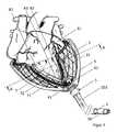
- FIG. 1shows an embodiment (10) of the device according to the invention in the implanted state.
- the device according to the inventionis implanted in a human body.
- the device according to the inventioncan also be implanted in an animal body, in particular in the body of a mammal, such as a dog, a cat, a rodent, a primate, a cloven-hoofed or an odd-toed ungulate.
- special adjustments to the shape and operation of the device according to the inventionmay be necessary to meet anatomical and / or physiological needs of each species justice.
- FIG. 1shows a human torso with the device according to the invention.
- the deviceconsists of a shell (2) which can at least partially enclose the heart (61), wherein components are introduced into the shell (2), which support the function of the heart (61). Furthermore, the device comprises a supply unit (30).
- the shell (2)which may at least partially enclose the heart (61), may transition from an unexpanded state to an expanded state.
- the shell (2)is self-expanding and can be introduced into a delivery system in the unexpanded state.
- the shell (2)may consist of a latticework or a braid.
- the meshcan be designed as a wire mesh.
- the latticework or wire meshmay be made at least in part of a shape memory alloy.
- the shell (2)encloses the heart (61) in the implanted state at least partially and is located within the pericardium (6). Embodiments in which the shell (2) is placed outside the pericardium (6) are also possible.
- the expandable shell (2)is at least one expandable unit, by means of which a pressure on the heart (61) can be exercised.
- the expandable unitmay be a mechanical unit that can assume an expanded and a non-expanded configuration. Such a mechanical unit can consist of spring elements that can be tensioned and relaxed, or of lever elements that can be folded and unfolded.
- the expandable unitsare chambers that can be filled with a fluid. Fluids used to fill a chamber are liquids, gases, or solids (such as nanoparticle mixtures), or mixtures of liquids and / or gases and / or solids.
- the at least one expandable unitcan be fixed in the shell (2).
- the at least one expandable unitis mounted on a shell, which can be introduced into the shell (2).
- the at least one expandable unitwill be explained in more detail in a later section of the description.
- the shell, which can be introduced into the shell (2)will be explained in more detail in a later section of the description.
- the shell (2)may further comprise at least one sensor and / or an electrode, by means of which at least one parameter of the heart (61) can be detected.
- the at least one sensormay be adapted to determine the heart rate, the ventricular pressure, the contact force between the heart wall and the at least one expandable unit, the systolic blood pressure or the diastolic blood pressure.
- the sensormay also be capable of measuring the pressure exerted by an expandable unit on a surface, the pH, the oxygen saturation, the electrical resistance, the osmolarity of a solution, or the flow through a vessel.
- the at least one sensormay be mounted in, on or on the shell (2). Preferably the at least one sensor mounted on a shell, which can be introduced into the shell (2).
- the at least one sensormay also be an electrode which is suitable for measuring a parameter such as the action potential on the myocardium during the excitation process or for stimulating a tissue with currents.
- a parametersuch as the action potential on the myocardium during the excitation process or for stimulating a tissue with currents.
- FIG. 1shows a supply unit (30) which can be worn outside the body.
- the supply unitcan also be partially or completely implanted in the body, which will be explained in more detail in subsequent paragraphs. If the supply unit (30) is worn outside the body, it can be attached to a chest belt, to a hip belt or to a stomach belt.
- the supply unit (30)has an energy store, by means of which the at least one expandable unit can be driven.
- the energy storemay be in the form of a rechargeable battery that provides electrical energy to expand the expandable unit.
- the accumulatorcan be changed.
- the supply unit (30)may also include an accumulator providing a compressed gas to inflate an inflatable chamber. Suitable gases include compressed air, CO 2 , or noble gases.
- the housing of the supply unit (30)itself can serve as a pressure accumulator housing.
- the supply unit (30)may further include pumps, valves, sensors and displays.
- the supply unit (30)may further include a microprocessor adapted to receive and process data from the at least one sensor. If the supply unit (30) is carried outside the body, the energy to be supplied can be transferred by a direct connection via a cable (4), or connectionless by eg electromagnetic induction.
- the data from the at least one sensorcan also be transmitted directly via a cable (4) or connectionless via a wireless technology, such as bluetooth.
- the device according to the inventionmay further comprise a cable (4) which connects the at least one expandable unit and / or the at least one sensor or the at least one electrode to the supply unit (30). If the supply unit (30) is connected directly to the at least one expandable unit and / or the at least one sensor or the at least one electrode, a cable (4) can be dispensed with. If the at least one expandable unit is a mechanical unit that can transition from an unexpanded state to an expanded state or from an expanded state to a non-expanded state by means of electrical energy, the cable (4) includes lines that suitable to transfer the necessary energy from the supply unit (30) to the expandable unit.
- the cable (4)contains at least one conduit which allows the flow of fluid from the supply unit (30) into the chamber.
- the cable (4)in this case includes at least one pneumatic or one hydraulic line.
- the deviceincludes a sensor or an electrode, in or on the shell, the at least one lead leading to the sensor or electrode may also be in the cable (4).
- Embodimentsmay also have separate cables for providing energy to the at least one expandable unit and to the at least one sensor or the at least one electrode.
- the cable (4) connecting the supply unit (30) to the at least one expandable unit and / or the sensor or the electrodemay be a single continuous cable or a multi-part cable.
- a cable (4)can be located on the at least one expandable unit and / or the at least one sensor or an electrode.
- a plug part (90)which can be connected via the couplable connection (91) to the supply unit (30).
- the connectioncan be coupled to the shell (2), at least an expandable unit and / or the at least one sensor or electrode.
- a cable (4) with plug part (91)can be attached to the at least one expandable unit and / or to the at least one sensor or electrode and also a cable can be attached to the supply unit (30) End preferably also a plug part is located.
- the cable (4)will be explained in more detail in a later section of the description.
- the plug part (90)will be explained in more detail in a later section of the description.
- FIG. 2shows an embodiment (11) of the device according to the invention in the implanted state, in which the supply unit (31) is implanted in the body.
- Preferred sites for the implantation of the supply unit (31)are chest cavity and abdominal cavity, which are separated by the diaphragm (63).
- the supply unit (31)may include an energy storage, by means of which the at least one expandable unit can be driven, which is located in the shell (2).
- the energy storemay be in the form of a rechargeable battery that provides electrical energy to expand the expandable unit.
- the supply unit (31)may further include sensors and one or more microprocessors. If the at least one expandable unit consists of at least one chamber which can be filled with a fluid, then the supply unit (31) can contain pumps, valves, and a pressure accumulator. The accumulator can provide a compressed gas to inflate an inflatable chamber can.
- Suitable gasesinclude compressed air, CO 2 , or noble gases.
- the housing of the supply unit (31) itself,can represent the accumulator housing.
- a preferred site for implantation of the delivery unit (31)is right-lateral in the thoracic cavity above the liver (62) and above the diaphragm (63).
- an accumulator (32)may preferably be implanted right-laterally in the abdominal cavity below the diaphragm (63) and above the liver (62).
- the pressure accumulator (32)can be connected to the supply unit (31) with a hose (33) which penetrates the diaphragm (63).
- the opening in the diaphragm necessary for the passage of the tube (33)can be sealed with a closure.
- the supply unitcan be connected by a cable (4) directly to the at least one expandable unit and / or the sensor or the electrode.
- a plug partcan be located at one end of the cable (4), which can be connected via a couplable connection to the supply unit (31) or to the at least one expandable unit and / or the sensor or electrode.
- the cable (4)preferably runs in the chest cavity above the diaphragm (63).
- a cable with plug partcan be attached to the at least one expandable unit and / or the at least one sensor or an electrode, and also a cable with a couplable plug part can be attached to the supply unit (31).
- an accumulator (34)can preferably be implanted subcutaneously in the abdominal wall.
- the energy required in the supply unit (31)can be transcutaneously transferred, for example by electromagnetic induction, from an extracorporeal control unit (35) to the accumulator (34) and transmitted from the accumulator (34) to the supply unit (31) by means of an electric cable (36).
- the extracorporeal control unit (35)may include inter alia a replaceable accumulator and / or a charger.
- the extracorporeal controller (34)may include, among other things, microprocessors and displays that may serve to monitor the system and display the operating status.
- the data from the at least one sensorcan connectionless via a wireless technology, such as bluetooth, to and between the supply unit (31) and the control unit (34) are transmitted.
- FIG. 3shows by way of example a human heart (61) and a shell (2), a shell (7) with expandable units (71, 72), sensors (81) and / or electrodes (82), a cable (4) with a plug part ( 90), a catheter (103) of a delivery system and a pericardial closure (5) of the device according to the invention.
- the shell (2)is shown in this embodiment in the form of a latticework.
- the gridworkmay consist of a continuous material from which parts have been removed or into which the openings have been formed.
- the shell (2)can be made of a tube or an individually shaped shell, into which the openings are cut.
- the slotted tubeis then stretched over shaping mandrels and normalized by means of a heat treatment, so that the clamped shape represents the new natural configuration of the tube.
- the slotted tubeis thus transferred into a shell (2) consisting of a lattice whose shape corresponds to an image of the heart.
- the slots in the tubego over into the openings of the latticework.
- the openingsare limited by struts.
- Several struts of an openingform individual cells of the latticework.
- the latticeworkcan preferably have diamond-shaped cells.
- the shape of the cellscan be modified by suitable cutting when slitting the tube. Alternatively, cells with a hexagonal honeycomb structure or cells of a polygonal structure can be produced in this way.
- the length and number of slotsalso defines the number of cell rows along the cardiac longitudinal axis of the shell (2). Longer cuts lead to longer struts, shorter cuts to shorter struts in the shell (2). Longer struts are more flexible than short struts.
- the length of the cellsis 5 mm to 50 mm, in particular 10 mm to 30 mm. The length of the cells may vary from cell row to cell row and may also be the same or vary within a cell row.
- the number of slots along the circumference of the tubedetermines the number of cells along the circumference of the shell (2). Fewer slots along the circumference result in a greater width of the resulting struts, increasing the number of slots along the circumference results in thinner struts. Wider struts are less flexible than thinner struts.
- the cutsmay be unevenly (non-equidistantly) distributed to each other so that regions with cells of greater strut width (higher structural rigidity) and regions with cells of smaller strut width (lower structural rigidity) can be created.
- Areas where higher structural rigidity is desiredmay be, for example, areas covering the left ventricle of the heart or areas forming the abutment for the expandable units (71, 72). Areas in which a lower structural rigidity is desired, for example, areas on the right ventricle.
- the wall thickness of the tube into which the slots are cutresults in the strut height of the shell (2).
- a larger strut heightleads to a stiffer behavior of the latticework.
- a lower strut heightleads to a more flexible behavior of the latticework.
- the wall thickness of the tubemay be between 0.2 mm and 2 mm, preferably between 0.4 mm and 1.5 mm, in particular between 0.6 mm and 1 mm.
- the wall thickness of the shellis equal to the wall thickness of the pipe.
- the latticeworkcan be cut from a tube whose diameter is between 4 mm and 20 mm, in particular between 8 mm and 15 mm. With the same number of slots results in a larger pipe diameter in a larger strut width.
- the manufacturing processguarantees that the latticework of the expanded shell (2) can be compressed again to the size of the tube from which it was cut. This can be particularly helpful if the shell (2) is to be introduced into a delivery system with a catheter (103) of smaller diameter. However, the shell can also be compressed to any intermediate size between the fully expanded heart-shaped latticework and the original tube diameter.
- the shell (2)may self-expand into the heart shape upon implantation / deployment from the delivery system.
- the length of the cells and / or struts of the latticeworkdetermines the opening angle during the expansion of the shell (2), in particular in the self-expandable shell.
- shell (2)may instead of a lattice work also consist of a network of wires.
- the wiresform crossing points that can be firmly connected together.
- the wirescan be welded together at the crossing points.
- the joining of the wires at crossing pointsincreases the stability of the shell (2).
- the crossing pointscan not be connected to each other. This can increase the flexibility of the shell (2) and thus lead to an easier compressibility of the shell (2). This can be especially helpful be when the shell (2) is to be introduced into a delivery system with a catheter (103) of smaller diameter.
- the shell (2)may also be firmly connected to one another at some of the points of intersection and may not be firmly connected to one another at other points of intersection.
- the stability and flexibility of the shell (2)can be adjusted.
- Areas that require increased stability in the implanted statecan be stabilized by connecting the wires at points of intersection. These may, for example, be areas which serve as abutments for expandable units (71, 72). Such abutments may be located directly below an expandable unit (71, 72) or adjacent areas with expandable units (71, 72).
- Areas that require increased flexibilitymay be areas that need to be more compressed when inserted into a delivery system than other areas. Areas that require increased flexibility may also be areas where increased flexibility supports the natural movement of the heart.
- the shell (2)has openings which are formed by the wires of a wire mesh, the struts of a latticework or the holes in a shell shell. These openings allow the shell (2) to be compressed, they allow mass transfer from the inside of the shell (2) to outside the shell (2) and vice versa, they reduce and allow the amount of material to be used for the shell (2) increased flexibility of the shell (2). Shapes, which are difficult to realize with continuous materials, are easier to form with braid or lattice-like structures.
- the openingsmay be square, diamond-shaped, round or oval.
- the apertures defined by the wires, the struts or the holes in a shell jackethave a diameter of about 1 mm to 50 mm, preferably 3 mm to 30 mm, preferably 5 mm to 20 mm.
- the diameter of an openingis defined as a pin opening, that is the diameter of the opening represents the largest diameter of a cylindrical pin which can be passed through an opening (a cell, a hole).
- the shell (2)is preferably made of a material that allows expansion.
- the shell (2)is formed of a material selected from the group consisting of nitinol, titanium and titanium alloys, tantalum and tantalum alloys, stainless steel, polyamide, polymer fiber materials, carbon fiber materials, aramid fiber materials, glass fiber materials, and combinations thereof.
- a self-expanding shell (2)is a material that is at least partially made of a shape memory alloy.
- Materials for shape memory alloysare, for example, NiTi (nickel-titanium, nitinol), NiTiCu (nickel-titanium-copper), CuZn (copper-zinc), CuZnAl (copper-zinc-aluminum), CuAlNi (copper-aluminum-nickel), FeNiAl ( Iron-nickel-aluminum) and FeMnSi (iron-manganese-silicon).
- the shell (2)preferably has a shape adapted to the individual heart shape of the patient.
- the individual heart shape of the patientscan be reconstructed from CT or MRI image data.
- the shell (2)is open at the top.
- the upper edge of the shell (2)preferably has loops of wire or stirrups formed by struts.
- the loops or strapscan serve as anchoring points for a sleeve (7) with at least one expandable unit (71, 72).
- At the lower end of the cup-shaped shellthere is preferably an opening through which one or more electrical leads (83) of the at least one sensor (81) or the at least one electrode (82) and / or leads (41) of the at least one expandable unit ( 71, 72) can be performed.
- the shape of the shell (2)represents, at least in part, the shape of a natural heart (61), preferably the lower part of a heart (61). Details of the shape of the shell (2) will be explained in more detail in a later section of the description.
- the shell (2)can be covered with a membrane (21), in particular with a membrane (21) made of polyurethane, silicone or polytetrafluoroethylene (PTFE).
- a membranemade of polyurethane, silicone or polytetrafluoroethylene (PTFE).
- PTFEpolytetrafluoroethylene
- Such a membranecan reduce the mechanical stress exerted by the shell (2) on the pericardium (6) or cardiac muscle (61).
- a membrane (21)may increase the biocompatibility of the shell (2) or prevent or reduce the attachment of biological tissue and / or cells.
- the membrane (21)can be mounted on the inside or on the outside of the shell (2).
- the membrane (21)can also be made by immersing the mesh or lattice-like shell (2) in an elastomer-containing liquid or liquid plastic and then cladding the mesh or mesh.
- the processcan be adjusted so that the openings of the braid or the grid of the membrane (21) can be covered or recessed. In the latter case, the membrane would then cover only the struts of the latticework or the wires of the mesh and not the interstices.
- a membrane (21) on the mesh or gridmay also enhance the abutment for an expandable unit (71, 72).
- an expandable unit (71, 72)is an inflatable chamber
- a membrane (21) over, on or on the mesh or gridcan prevent parts of the chamber from being forced through the mesh or grid during expansion of the chamber ,
- the membrane (21)can further prevent too large expansion of the shell (2), in particular during inflation of an inflatable chamber.
- a membrane (21) on a grid or braidcan ensure that expansion of an expandable unit located on the grid or braid is only in a direction inwardly of the braid or grid.
- the membrane (21)does not hinder the compressibility of the shell (2) when introduced into a delivery system.
- the membrane (21)may be 0.05 mm to 0.5 mm thick, in particular wherein the membrane is 0.1 mm to 0.3 mm thick.
- the shell (2) and / or the membrane (21)may also comprise an active agent, for example an antithrombotic agent, an anti-proliferative agent, an anti-inflammatory drug, an anti-neoplastic Active ingredient, an anti-mitotic agent, an anti-microbial agent, a biofilm synthesis inhibitor, an antibiotic agent, an antibody, an anticoagulant agent, a cholesterol lowering agent, a beta-blocker, or a combination thereof.
- an active agentfor example an antithrombotic agent, an anti-proliferative agent, an anti-inflammatory drug, an anti-neoplastic Active ingredient, an anti-mitotic agent, an anti-microbial agent, a biofilm synthesis inhibitor, an antibiotic agent, an antibody, an anticoagulant agent, a cholesterol lowering agent, a beta-blocker, or a combination thereof.
- the active ingredientis in the form of a coating on the shell (2) and / or the membrane (21).
- the shell (2) and / or membrane (21)may also be coated with extracellular matrix proteins, in particular fibronectin
- FIG. 3shows a shell (2), in which a shell (7) with expandable units (71, 72) is introduced in the form of inflatable chambers.
- the expandable unit (71, 72)is powered by a conduit (41) located in the cable (4).
- the expandable unit (71, 72)may be a hydraulic or a pneumatic chamber.
- the expandable unit (71, 72)can be attached directly to the shell (2) without a sheath (7).
- the expandable unit (71, 72)may also be mounted on a sleeve (7) and the sleeve (7) may be fixed in the shell (2).
- the expandable unit (71, 72)may be configured to exert pressure on the heart (61).
- This pressuremay be a permanent pressure or it may be a periodic pressure.
- the device according to the inventionmay comprise various types of expandable units (71, 72).
- the devicemay comprise at least one augmentation unit (71).
- the devicemay comprise at least one positioning unit (72).
- the augmentation unit (71) and / or the positioning unit (72)can be mounted directly on the shell (2) or on a shell (7) which is inserted into the shell (2).
- An augmentation unit (71)is a unit that can be periodically expanded and expanded, thus exerting pressure on the heart (61). This pressure is preferably applied in areas on the heart muscle, under which there is a heart chamber. By applying pressure to a heart chamber through the augmentation unit (71) becomes the natural Pumping movement of the heart (61) supports or replaces, and the blood in the heart (61) is pumped out of the chamber into the laxative artery. A pressure applied to a right ventricle by an augmenting unit (71) results in ejection of the blood from the right ventricle into the pulmonary artery. A pressure exerted by an augmenting unit (71) on a left ventricle leads to ejection of the blood from the left ventricle into the aorta.
- the positioning of the at least one augmentation unit (71) in the shell (2)will be explained in more detail in a later section of the description.
- a positioning unit (72)is a unit that can also be expanded.
- a positioning unitis more statically expanded than periodically during operation of the device to support the function of a heart.
- the positioning unit (72)can be expanded to fix the device to the heart and to ensure the fit of the device.
- a positioning unit (72)can also be responded to changes in the heart muscle (eg shrinkage of the heart muscle due to lack of fluid or expansion of the heart muscle due to fluid intake of the patient). If the heart muscle breaks down or over a period of time, a positioning unit can be further expanded and relaxed to ensure a perfect fit.
- the positioning unit (72)can also serve, for example, for the device not losing contact with the heart wall over the duration of a heartbeat.
- the positioning unit (72)can counteract the pathologically induced progressive expansion of the damaged heart muscle in heart failure patients.
- the positioning of the at least one positioning unit (72) in the shell (2)will be explained in more detail in a later section of the description.
- At the lower end of the shell (2)may be an opening through which the conduit (83) from the at least one sensor (81) or the at least one electrode (82) and / or the conduit (41) of the at least one expandable Unit (71,72) can be performed.
- the openingmay be attached to the lower distal end of the shell (2).
- the openingcan also be mounted laterally on the shell (2). Is shown in FIG. 3 an opening at the lower distal end of the shell (2), through which a cable (4) comprising all lines (41, 83) is guided.
- the multiple cablesmay be passed through an opening of the shell (2) or through a plurality of openings of the shell (2).
- a plug part (90)is mounted, with the aid of which the at least one sensor (81) or the at least one electrode (82) and / or the at least one expandable unit (71, 72) connected to a supply unit can be.
- the shell (2)is mounted within the pericardium (6).
- the cable (4)is then passed through the pericardium (6).
- the device according to the inventionmay comprise a pericardial closure (5). This can seal the opening of the pericardium (6) necessary for the passage of the cable.
- the pericardium (6)is a connective tissue sac that surrounds the heart (61) and gives the heart (61) freedom of movement through a narrow sliding layer.
- a pericardium closure (5)can surround the pericardium Cable (4) are attached.
- the pericardium seal (5)seals the opening of the pericardium (6) to the cable (4).
- the pericardium closure (5)may comprise a first closure element with a first sealing lip and a second closure element with a second sealing lip. Through a central lumen of the closure, a cable (4) can be performed.
- the first sealing lip and / or the second sealing lipcan seal off the pericardial opening.
- the first and second closure elementscan be coupled.
- the first and the second closure elementcan be secured with a mechanism. Possible mechanisms for securing the closure elements are screw mechanisms, clamping mechanisms or a bayonet closure.
- the first closure element and / or the second closure elementcan be expandable, preferably self-expandable.
- the pericardial closure (5)will be explained in more detail in a later section of the description.
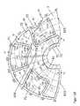
- FIGS. 4a and 4bshow a section through the heart (61) and a part of the device for supporting the function of a heart (61) along the line AA in FIG FIG. 3 ,
- the following layersare shown from the outside to the inside: the shell (2) with a membrane (21), a shell (7) with at least one expandable unit (71, 72), a sensor (81), an electrode (82) and Heart (60) in transverse section.
- three augmentation units (71) and three positioning units (72)are shown.
- the expandable units (71, 72)are shown in the unexpanded state.
- FIG. 4bthe augmentation units (71) are shown in an expanded state.
- the at least one expandable unit (71, 72)is located in a region adjacent to a heart chamber.
- Expansion of the at least one expandable unit (71, 72)can reduce the volume of the ventricle and thus result in expulsion of blood from the chamber.
- the at least one sensor (81) or the at least one electrode (82)is mounted at a location at which at least one parameter of the heart (61) can be measured.
- An electrode (82)may be attached at a location where the heart muscle can be stimulated.
- a sensor (81) and an electrode (82)are shown on the expandable units (71, 72).
- the sensors (81) and / or the electrodecan also be located in the wall of an expandable unit (71, 72), on the inside or outside of the envelope (7), in the envelope (7) or on the shell (2). to be appropriate. There may also be two, three, four, five or more sensors and / or electrodes mounted on the sheath.
- FIG. 5shows a delivery system (100) by means of which the device for supporting the function of a heart can be implanted.
- the delivery system (100)consists of a catheter (103) having a lumen.
- the catheter (103)is an elongated tubular member into which the device for supporting the function of a heart may be inserted in a compressed state.
- the cross section of the catheter (103) and / or the lumencan be round, oval or polygonal.
- the delivery system (100)may further comprise a guide wire (101) and / or a dilation element.
- the dilation membermay be a soft tapered tip (102) with shank.
- the soft conical tip (102)may have a round, oval or polygonal lumen in the middle.
- the soft conical tip (102)can be slid over the guidewire (101) and the puncture can be dilated without injuring the epicardium.
- the distal portion of the catheter (103) of the delivery system (100)can be passed.
- a first closure element (51, 52) of the pericardial closuremay be attached or otherwise secured.
- the catheter (103)can be plugged onto a cone (55) located at the end of the first closure element (51, 52).
- a coneis located on the side of the catheter and the first closure element can then be attached to this.
- the catheter (103) with the attached first closure element (51, 52) of the pericardial closurecan be guided over the shaft of the soft tip (102) and inserted into the pericardium (6).
- the catheter (103) and the first closure element (51, 52) of the pericardial closuremay be non-coupled parts. In this case, initially only the catheter (103) is introduced into the pericardium (6) and the first closure element (51, 52) can then be pushed over the catheter into the pericardium (6) or through the lumen of the catheter (103) in the pericardium (6).
- the first closure element (51, 52)may be a self-expandable Be closure element and can unfold in the pericardium (6).
- a non-expandable part (51) of the first closure elementcontains a self-expandable sealing lip (52) or a sealing lip (52), which can engage upon insertion of the first closure element (51, 52) and spreads in the pericardium (6).
- the first closure member (51, 52)may expand to a mushroom-shaped or umbrella-like shape.
- a second occlusive member (53, 54)may be inserted over the catheter (103) or deployed through the catheter (103). For example, the second closure member (53, 54) may be moved over the catheter (103) of the delivery system (100) to the distal end of the delivery system (100) and may then be coupled to the first closure member (51, 52).
- the second closure element (53, 54)may be expandable or non-expandable.
- the second closure element (53, 54)can be coupled to the first closure element (51, 52).
- the second closure member (51, 52)is self-expandable and may take on a mushroom-shaped or umbrella-like shape in an expanded form.
- the second closure element (53, 54)can be secured with the first closure element (51, 52). Shown in FIG. 5 is a screw mechanism.
- Other mechanisms for securing the closure members (51, 52, 53, 54)include a clamping mechanism or a bayonet lock.
- the catheter (103) of the delivery system (100)can still remain on the cone (55) of the first closure element (51) or remain in the lumen of the closure element (51, 52).
- the shellmay be connected to the at least one sensor or at least one electrode and / or to the at least one expandable unit through the lumen of the catheter (103 ) are introduced.
- the shellis preferably self-expanding and after expansion surrounds the heart (61) at least in part.
- At the lower end of the shellmay be a plug part or a cable with a plug part.
- the supply unitcan be attached directly to the shell or connected to the shell via a cable.
- the delivery system (100)can be removed. This can be on the Delivery system (100) and / or on the catheter (103) a predetermined breaking point (104) are located. Preferably, one or more predetermined breaking points (104) are located along a longitudinal axis of the delivery system (100).
- the predetermined breaking point (104)can represent a predetermined breaking line.
- the delivery system (100)may also include gripping members (105) by means of which a force can be exerted on the delivery system (100).
- a force directed sideways from the catheter (103) of the delivery system (100)can be exerted, which is suitable for breaking the predetermined breaking point (104).
- FIG. 6shows a step of implantation of the device according to the invention.
- the shell (2)which is preferably self-expanding, can pass through the lumen of the delivery system catheter (103) and the lumen of the first closure element (51) are passed.
- the expansion of the shell (2)begins. Shown in FIG. 6 is also the second closure element (58, 59) before it has been coupled to the first closure element (51, 52).
- the second closure element (58, 59) in this exemplary embodimentis an annular element (58), for example a nut, on the distal side of which a sealing washer (59) can be attached.
- the second closure element (58, 59)may be expandable or non-expandable.
- the second closure element (58, 59)can be displaced on the catheter (103).
- the first (51, 52) and the second closure element (58, 59)threaded portions which can be screwed together.
- FIG. 7shows a step of implantation of the device according to the invention.
- the first closure element (51, 52)is coupled to the second closure element (53).
- the pericardium (6)can thereby be sealed.
- the expandable shell (2)is partially in the pericardium (6) and can be expanded.
- FIG. 7shows markings (25) which are mounted on the shell (2).
- the device according to the inventiongenerally includes at least one marker (25) which can facilitate correct placement of the tray (2).
- the marking (25)may be an optical marking, in particular a color marking.
- the marker (25)may be a phosphorescent or fluorescent marker that facilitates its perception in a dark environment. Such environments can be in the operating room itself and can be caused by, among other things, shadows. Such environments can also be inside the body of a patient.
- the marker (25)may be made of a material that can be displayed by means of imaging techniques. Suitable imaging techniques include X-ray, CT, and MRI.
- the marker (25)may be formed of a more radiopaque material than the material of adjacent regions.
- the marker (25)may take a mark in the form of a point, a circle, an oval, a polygon or the shape of a letter. Other shapes may be areas created by joining dots. For example, the shape may be a crescent or a star.
- the marker (25)may be mounted on the shell (2) or mounted on a shell.
- the markermay be in the form of a line. The line can start from an upper edge of the shell (2). The line may extend from an upper edge of the shell (2) to a point on the lower tip of the shell (2).
- the linecan run from the upper edge of the shell perpendicular to the lower tip of the shell (2).
- the starting point of the line at the upper edge of the shell (2)may be at a location that, when implanted, is near or at an area equal to the septum of the heart.
- the mark (25)may be located at intersections of the mesh or grid. If the shell (2) consists of a shell casing into which holes have been formed, the marking (25) can be worked into the shell casing. For example, a hole can be made with a predefined shape, which then serves as a mark (25).
- the delivery system and / or catheter (103) of the delivery systemmay include one or more markers (106).
- a marker (106) on a delivery systemmay be shaped like a marker on a tray.
- the mark (106)may have the shape of a dot or the shape of a line.
- a mark (106) in the form of a linemay be a line at least partially describing a circumference of the delivery system.
- a mark (106) in the form of a linemay be a longitudinal line along an axis of the feeding system.
- a mark (106) in the form of a linemay be a straight line or a meandering line.
- a mark (106) in the form of a linemay be a line oblique on a catheter (103) of a delivery system.
- a marker (103)may facilitate the orientation of the delivery system during implantation.
- a marker (103) on or on the delivery systemmay be in registry with a line on or on a medical implant.
- the medical implantmay be a device for supporting the function of a heart that can be compressed. In a compressed state, the device can be introduced into a delivery system.
- One or more markings (25) on or on the devicemay be registered with one or more markers (106) on or on the delivery system.
- Such markings (25, 106)facilitate the orientation of a medical implant.
- Marks (25)may also be along an axis of a medical implant. Such markers (25) may be helpful to track the progress of deploying a medical implant from a delivery system.
- the delivery system and / or a catheter (103)may be made of a transparent material that allows the medical implant to be perceived during insertion.
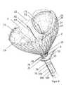
- FIG. 8shows the fully expanded configuration of the shell (2) and a sheath (7) of the device according to the invention.
- the shell (2)is in this Embodiment of a lattice work or wire mesh formed having at the top and / or at the bottom of the shell (2) struts in the form of straps or loops (26, 28). If the shell (2) is formed from a shell casing into which holes have been formed, the shell (2) can be designed at the upper edge and / or at the lower edge in such a way that at least one bracket is located at the upper edge and / or at the lower edge Edge of the shell (2) is located. In the FIG.
- the 8 illustrated shell (2)comprises a sheath (7) which is introduced into the shell (2).
- On the sheath (7) and the shell (2)can be at least one expandable unit.
- the casingscan be attached to the loops (26, 28) or brackets of the shell (2).
- a sheath on the loops (26, 28) or ironing of the shell (2)are hung.
- the sheath (7)at least one pocket (27), which can be slipped over at least one loop (26, 28) or at least one strap.
- Another embodimentmay include a sheath (7) which projects over the shell (2) and which is then everted around the stirrups / loops (26) and / or at the lower edge at the upper edge of the shell (2).
- the everted portion of the sheath (7)can be connected through the latticework or wire mesh with the non-everted portion of the sheath.
- the eversioncan be welded or glued through the latticework or the wire mesh.
- This inversioncan also form a pocket (27) running all or around part of the sheath (7), which pocket can be hooked into the upper edge and / or the lower edge of the sheath (2).
- the attachment by everting a part of the shell around the upper edge of the shellallows a precise fixing of the shell in the shell.
- the sheath (7)may be made of plastic, polymer, rubber, rubber, latex, silicone or polyurethane.
- the sheath (7)may have a thickness of 0.1 mm to 1 mm, preferably 0.2 mm to 0.5 mm.
- the shell (2)may have an opening at the lower end. A part of the sheath (7) can project through this opening, for example, between 3 mm and 2 cm of the shell protrude.
- the sheath (7)can also be open at the bottom, thus improving the fluid exchange from the space inside the sheath (7) to the space between sheath (2) and pericardium (6). For example, pericardial fluid can flow in and out through the opening in the sheath (7).
- the upper edge of the shell (2)preferably runs parallel to the heart valve plane, but may have areas of a recess (22).
- the recess (22) in the shell (2)may be required from anatomical conditions, for example, not to compromise the inferior vena cava, which extends from the dorsal direction of the right atrium of the heart. A compromise of the inferior vena cava would lead to a lower influence congestion (obstruction of the filling of the right atrium).
- a recess (22)may also be required due to other anatomical or cardiac structures. If the shell (2) designed as a latticework or wire mesh, so the recess (22) can be prepared by subsequent separation of struts or wires.
- a manufacturing methodcan be selected in which the recess (22) does not have to be made afterwards.
- the wire wrapmay be adjusted to make the wires shorter at the location of the recess (22) and closer together the crossing points.
- the recess (2)can be made by suitable cutting of the tube and correspondingly modified slotting. The slit can be adjusted so that despite the recess (22), the number of cells in the shell (2) remains the same. This may be necessary for stability reasons.
- the slit of the tubecan be modified such that one, two or three cell rows are omitted at the location of the recess (22).
- the sheath (7)can be adapted to the recess (22).
- the recessmay have a length of 2 cm, 3 cm, 4 cm, 5 cm, 6 cm, 7 cm or more.
- the depth of the recess, measured from the imaginary uninterrupted upper shell edge to the point of the recess which The heart tip closest tocan be between 1 mm and 40 mm, in particular between 3 mm and 15 mm. In the circumferential direction, the recess is positioned where the inferior vena cava opens into the right atrium.
- the recessmay be arcuate, semicircular, rectangular or polygonal.
- the recess (22)may be so long that it corresponds to the circumference of the upper edge of the shell (2).
- the recess (22)can then begin and end at the point of the upper edge of the shell (2) which faces the cardiac structure to be omitted, for example the inferior vena cava.
- the recess (22)defines a plane which is tilted to the heart valve plane and which comes to rest at the point to be spared 1 mm to 40 mm, in particular 3 mm to 15 mm lower than when the upper edge of the Shell (2) would run parallel to the heart valve plane.
- the sheath (7)has a recess (22) which in its shape, position and dimension substantially coincides with the recess (22) in the shell (2), which frees the anatomical area around the inferior vena cava. A compromising of the inferior vena cava by the sheath (7) and a subsequent obstruction of the filling of the right atrium is thereby prevented.
- the recesses (22) in the shell (7) and shell (2)can be brought into coincidence with each other.
- the shell (2)has a plurality of markings (25). As already described, these markings (25) can assume different shapes or positions. In the present case, the markings (25) are attached to an upper edge and to the lower tip of the shell (2).
- one, two, three, four or more extension struts (23)can be attached to the shell.
- the extension strutsare an extension of the shell (2) in the direction of the cardiac longitudinal axis.
- the extension struts (23)can run in the direction of an imaginary heart tip touch or not touch completely and from there in the direction of the cardiac longitudinal axis of the heart protrude.
- the extension struts (23)can be collected in a common sleeve become.
- the extension struts and / or the sleevecan be connected to the cable of the device, for example by gluing.
- the extension struts (23)can serve to fix the shell in the axial direction.
- the extension struts (23)limit the rotation of the shell around the cardiac longitudinal axis only partially. If the shell is made of a wire mesh, the extension struts (23) may be the extended ends of wires. The extension struts (23) and the wire mesh are thus a part. If the shell (2) consists of a latticework made of a slotted tube, then the latticework with the extension struts (23) can be made from a single tube by suitable cutting. The latticework and the extension struts (23) are thus a part.
- the extension struts (23) and the shell (2)can also be multi-part, whereby the extension struts (23) after manufacture of the shell (2) are attached to this, for example by a Ein vonmechanismus or by material connection (welding, gluing).
- the length of the extension struts (23)can be between 1cm and 10cm, especially between 4cm and 7cm.
- the shell (2)may comprise only the above-described recess (22) and no extension struts (23). Alternatively, the shell (2) may comprise both the recess (22) described above and the extension struts (23) described above. The shell (2) may also comprise only the above-described extension struts (23) and no recess (22).
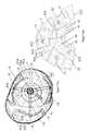
- FIG. 9shows a step of implantation of the device according to the invention.
- the heartis not shown.
- the first closure element (51, 52) and the second closure element (53) of the pericardial closureare coupled together.
- the device for supporting the function of a hearthas already been partially deployed from the delivery system. Shown is a self-expanding shell (2) into which a shell (7) has been introduced. On the shell are expandable units (71) in the form of bellows-shaped chambers, a sensor (81) and an electrode (82) attached.
- the shell (2) and the shell in this embodimentessentially substantially equalize the shell and the shell, respectively FIG. 8 ,
- the sheath (7) shown in this embodimentstill expandable units (71) were applied.
- the sheath (7)may be the underside of the expandable units (71).
- the expandable units (71)may be adapted to the shape of the heart, the shell (2) and / or the sheath (7).
- One, two, three, four, five, six, seven or more expandable units (71)can be applied to the envelope (7).
- the expandable units (71)can exert pressure on the heart muscle. This pressure is preferably applied in areas on the heart muscle, below which there is a heart chamber, but always below the heart valve plane.
- the expandable units (71)When the expandable units (71) are positioned in the lower region of the sheath (7) and / or shell (2) close to the apex of the heart, as the expandable units (71) expand, the myocardium in the direction of the cardiac longitudinal axis becomes upward to the heart valve plane pressed. If the expandable units (71) are arranged in the upper region of the sheath (7) and the shell (2), the heart muscle is pressed perpendicular to the longitudinal axis of the heart when the expandable units (71) expand. Pressure is then exerted on the heart muscle parallel to the heart valve plane (laterally on the ventricles).
- the expandable units (71)can also be positioned at any position between the lower edge and the upper edge of sheath (7) and shell (2), whereby the pressure of the expandable units (71) in their expansion in proportion to the heart longitudinal axis and proportionately parallel to the heart valve plane acts.
- FIG. 9are expandable units (71) are shown located at the top of the shell (7).
- the pressuretherefore acts as parallel as possible to the heart valve plane.
- the counterforce on the device in the direction of the cardiac longitudinal axisis thereby kept low.
- a displacement of the device in the direction of the heart longitudinal axis away from the heart (dislocation), caused by expansion of the expandable units (71)is thereby minimized.
- the self-expanding shell (2) and the sheath (7) in this illustrationhave a recess (22) so as not to compromise the inferior vena cava in the implanted state of the device.
- the expandable units (71)can be adapted in size, shape and position to the recess (22) in the shell (2) and the shell (7), so that they neither in the expanded, nor in the unexpanded state, the recess (22) cover.
- extension struts (23)fix the shell (2) in the axial direction of the cable and stabilize the device as a whole.
- the extension struts (23)may be connected to the cable of the device.
- a part of the extension struts (23)may also remain after implantation in the pericardial closure or outside the closure elements (51, 52, 53) of the pericardial closure. If, as a result of the expansion of the expandable units (71), the device experiences a force in the direction of the heart's longitudinal axis away from the heart, this force can be partly removed via the shell (2), the extension struts (23) and the supply line (cable), without resulting in a dislocation of the device.
- the extension strutsmay have (23) at their ends holes, straps, loops or angled ends which facilitate minimally invasive explantation of the shell (2) and sheath (7).
- the angled ends, the holes, straps or loopsdo not hinder the fixation of the extension struts (23) in the cable.
- ends of the extension struts (23)may be inside the cable.
- the cablecan be cut approximately at the level of the ends of the extension struts (23) and the shell (2) with the sheath (7) at the ends of the extension struts (23) by the closure elements (51, 52, 53) be pulled out of the pericardium (6).
- a toolcan be coupled to the angled ends of the extension struts (23) or the holes, stirrups or loops located at the ends of the extension struts (23).
- FIGS. 10a -cshow different views of a pericardial closure (5).
- the pericardial closure (5)serves to prevent the loss of pericardial fluid, or even the possibility of artificial pericardial fluid, even with the addition of drugs or other therapeutic agents to be able to apply.
- the avoidance of loss of pericardial fluidalso serves to avoid adhesions of the system with the epicardium.
- the pericardial closure (5)generally consists of a first closure element (51) and a second closure element (52).
- the first closure member (51)has a central lumen and the second closure member (53) has a central lumen.
- the first closure element (51)can be coupled to the second closure element (53).
- the coupled pericardial closure (5)After coupling the first closure element (51) to the second closure element (52), the coupled pericardial closure (5) has a lumen extending through the pericarp closure (5).
- the lumenmay be formed solely by the central lumen of the first closure member (51), or the lumen may be formed solely by the central lumen of the second closure member (53). In another embodiment, the lumen can also be formed from the two lumens of the two coupled closure elements (51, 53).
- a gasket, o-ring, labyrinth seal or other sealing element (56)may be located in the lumen.
- a sealing element (56) in the lumen of the pericardial closurecan seal the pericardial closure (5) against an object protruding through the pericardial closure (5).
- a cablecan be passed through the pericardial closure (5), which is then sealed against the pericardial closure (5).
- a sealing element (56) in the lumenmay serve not only to seal, but also to fix an object projecting through the lumen of the pericardial occlusion.
- the sealing element (56)can be mounted on both closure elements (51, 53) or only on one of the two closure elements (51, 53).
- the first closure element (51)can be secured to the second closure element (53) by means of a mechanism.
- a mechanism for backup a first closure element (51) with a second closure element (53)may comprise a screw mechanism or a clamping mechanism.
- a mechanism for securing a first closure member (51) to a second closure member (53)may also include a bayonet closure.
- the first closure element (51) and the second closure element (53)may be made of the same material or of different materials. Suitable materials for the first closure element (51) and / or the second closure element (53) include plastics, metals, ceramics or combinations thereof.
- a first sealing lip (52)can be attached to the first closure element (51).
- the first sealing lip (52)may be part of the first closure element (51) or it may be attached to the first closure element (51).
- a second sealing lip (54)can be attached to the second closure element (53).
- the second sealing lip (54)may be part of the second closure element (53) or it may be attached to the second closure element (53).
- the first sealing lip (52) and the second sealing lip (54)may be formed of the same material or of different materials.
- One or both sealing lips (52, 54)may be part of the respective closure element (51, 53) and be formed of the same material as the associated closure element (51, 53).
- the first sealing lip (52) and / or the second sealing lip (54)may be formed of plastic (preferably an elastomer), rubber, rubber, silicone, latex or a combination thereof.
- the first sealing lip (52) and / or the second sealing lip (54)may be disk-shaped.
- the first sealing lip (52) and / or the second sealing lip (54)may have a concave or convex bend. Curved sealing lips (52, 54) can adapt better to the anatomical conditions.
- the pericardiumhas a convex shape in the area of the apex of the heart.
- the first sealing lip (52) and / or the second Sealing lip (54)may have reinforcements. With increasing radial distance from the lumen of the pericardial seal to the outside, the first sealing lip (52) and / or the second sealing lip (54) have increased flexibility. Increased flexibility in edge regions of a sealing lip (52, 54) can promote the sealing properties of the sealing lip (52, 54) and also the anatomically correct positioning of the sealing lip (52, 54). An increased flexibility in edge regions of a sealing lip (52, 54) can be achieved by the choice of material. Each of the sealing lips (52, 54) may consist of one or more materials.
- Reinforcements in a sealing lip (52, 54)may be concentric reinforcements or radial reinforcements. Reinforcements can be achieved by varying material thicknesses or by introducing a reinforcing material.
- the reinforcing materialmay be the same material as the base material of the sealing lip (52, 54) which has been transferred to another form of material.
- regions that are not to be reinforcedmay be weakened by transferring the material of the sealing lip (52, 54) to a weaker form of the material. A weakening of the material can be brought about by the action of energetic radiation, such as heat.
- Reinforcements of the materialcan also be achieved by applying material, wherein the applied material may be the same material as the base material of the sealing lip (52, 54), or wherein the applied material is a different material than the base material of the sealing lip (52, 54). can represent.
- Suitable materials for reinforcing parts of a sealing lip (52, 54)are metals, ceramics, rubber and or a combination thereof.
- a coupling mechanismmay be located on one of the two closure elements (51, 53), which allows the coupling of a closure element (51, 53) with the delivery system or a catheter of the delivery system.
- the coupling mechanismmay for example consist of a cone (55) located on the first closure element (51) on which the delivery system or a catheter of a delivery system can be clamped. The clamping effect can be achieved for example by the diameter of the Cone (55) is greater than the luminal diameter of the delivery system.
- the coupling mechanism for coupling the pericardial closure (5) to the delivery systemmay also be located on the second closure element (53).
- the coupling mechanismmay also be present as a separate component next to the closure elements (51, 53) and connect the delivery system with one of the two closure elements (51, 53) of the pericardial closure (5).
- Other embodiments of the coupling mechanisminclude, but are not limited to, a non-conical (eg, cylindrical) extension on one of the closure members (51, 53) to which the delivery system may be applied or adhered, or an embodiment wherein the catheter of the delivery system and a closure member are a single integral member represent. In the latter embodiment, after successful insertion and securing of the pericardial closure (5), the catheter can be separated from the closure element (51, 53) of the pericardium closure (5) by means of a predetermined breaking point.
- Engagement elements (57)may be located on one or both closure elements (51, 53). These engagement elements (57) can be used to exert a force on one or both closure elements (51, 53) which is suitable for coupling and / or securing the closure elements (51, 53). Engagement elements (57) on one or both closure elements (51, 53) may be holes, indentations or elevations.
- the engagement elements (57)can be circumferentially mounted around the closure element (51, 53) at the same distance from each other. The circumferential distance between the engaging elements (57) may also be different. In the Figures 10a-c six engaging elements (57) are shown in uniform circumferential distance from each other.
- the six engaging elements (57)are mounted at an angular distance of about 60 °. With two, three, four, five, six, eight or more uniformly arranged engagement elements (57), the angular spacing can be respectively 180 °, 120 °, 90 °, 72 °, 60 °, 45 ° or less.
- the engaging elements (57)can also be arranged irregularly.
- FIG. 11shows a pericardial closure (5) and a tool (11) for securing a pericardial closure (5).
- the in FIG. 11 shown pericardial closure (5)is substantially the same as in FIG. 10 shown closure match.
- the tool (11)is exemplified as an elongated tubular tool.
- elements (111)At the distal end of the tool (11) are elements (111) which can at least partially be brought into engagement with the engagement elements (57) of a closure element (53).
- FIG. 11In the in FIG. 11
- six inwardly pointing elevations (111)are engaged with the six engagement elements (57) of the closure element (53), in this case six indentations on the closure element (53) can be brought.
- the tool (11)has substantially the same number of elements (11) which are complementary to the engagement elements (57) of the closure element (53).
- This in FIG. 11 illustrated tool (11)is a tubular tool, which consists of a completely encircling tube.
- the tubular element of the tool (11)may also be a half-tube, quarter-tube, or one-third tube.
- only one stem or several stemsmay be attached to a distal annular tool.
- a stemmay extend from the annular tool in the longitudinal direction.
- a stemmay also extend laterally away from a longitudinal axis of the tool.
- Other not shown embodiments of the tool (11)may be in the form of a modified ring key or a modified open-end wrench.
- FIG. 12shows a connector system consisting of two connector parts (90, 92).
- the device for supporting the function of a heartconsists of a shell with at least one sensor or at least one electrode and / or at least one expandable unit, wherein the at least one sensor or electrode and / or the at least one expandable unit is connected to a supply unit.
- the at least one sensor or the at least one electrode and / or the at least one expandable unitcan be connected directly to the supply unit.
- the at least one sensor or the at least one electrode and / or the at least one expandable unitcan be connected to the supply unit via a cable (4).
- the at least one sensor or the at least one electrode and / or the at least one expandable unitcan be connected directly to the supply unit via the cable (4) or the at least one sensor or the at least one electrode and / or the at least one expandable unit can be connected to the supply unit.
- the supply unitmay comprise a plug part (92).
- the plug part (92)can be attached directly to the supply unit.
- the plug part (92)can be connected to the supply unit via a cable (4).
- the at least one sensor or the at least one electrode and / or the at least one expandable unitmay comprise a cable (4). At the end of the cable (4) may be a plug part (90).
- the plug part (90) at the end of the cable of the at least one sensor or the at least one electrode and / or the at least one expandable unitcan be coupled to the plug part (92) of the supply unit.
- the plug part (90) of the sensor or the electrode and / or the at least one expandable unitmay be a male plug part or a female plug part.
- a female connector part on the side of the sensor or the electrode and / or the at least one expandable unitmay be advantageous, since the female connector part, in contrast to the male connector part no pins (951) or other connections that protrude and break it.
- the plug systemmust be decoupled and a new supply unit coupled into the plug part (90) of the sensor or the electrode and / or the at least one expandable unit. This can lead to breakage of pins (951) or other connections. If these pins (951) or connections on a male connector part on the side of the shell with the at least one sensor or the at least one electrode and / or the at least one expandable unit, an exchange of the shell may be required. A female plug part on the side of the shell with the at least one sensor or the at least one electrode and / or the at least one expandable unit may be advantageous since a breakage of Pins (951) or other connections to a female connector part can not occur.
- the plug system (90, 92)generally consists of two plug parts.
- the device according to the inventioncan consist of a plug system (90, 92) for the at least one sensor or the at least one electrode and / or the at least one expandable unit or of a plurality of plug systems. If multiple plug systems used, a plug system for electrical cables and a connector system for hydraulic and / or pneumatic lines may be present.
- Connector system shown (90, 92)is a connector system comprising connections for the supply of the at least one sensor or the at least one electrode and the at least one expandable unit.
- connectiondepends on how many sensors or electrodes and how many expandable units are used, the number need not correlate directly with the number of sensors or electrodes and / or the number of expandable units.
- Cables of conduitsare possible on both sides of the connector system (90, 92) and a pneumatic or hydraulic conduit can supply one, two, three, four, five, six or more inflatable chambers.
- the filling of the multiple chambers by a linedoes not have to be parallel, it can also be done individually by controllable valves.
- an electrical lead in the cablecan be used for multiple sensors or electrodes and switches can individually control circuits.
- connector system (90, 92)comprises four hydraulic or pneumatic connections (93, 94) and a connection for electrical lines (95, 96).
- electrical connection (95, 96)has 16 connection elements in the form of pins (951) and pin sockets (961). More or less connections for electrical lines (95, 96) and / or pneumatic or hydraulic lines (93, 94) can be present in a plug system. There may be one, two, three, four, five, six, seven, eight, nine or ten connections for pneumatic or hydraulic lines (93, 94). There may be one, two, three, four, five, six, seven, eight, nine, ten, twelve, fourteen, sixteen, twenty, or more electrical lead connections (95, 96).
- each of the terminals (93, 94, 95, 96) in one or both of the plug parts of the plug system (90, 92)may have its own gasket (931, 952).
- the seal (931, 952) of the individual terminals (93, 94, 95, 96)may be a sealing band or a sealing ring.
- the connector system (90, 92)may additionally or only have a seal inside the connector system (973) or around the connector system.
- a seal over the plug systemmay be a sealing tape or a gasket.
- the plug parts (90, 92)can be coupled together to form the plug system (90, 92).
- the plug parts (90, 92)may also have a guide nose (972) and a guide groove (974).
- the guide nose (972) and the guide groove (974)can prevent incorrect coupling of the two connector parts and / or twisting of the connector parts during the coupling process.
- the coupled connector parts (90, 92)can also be secured with a mechanism (971).
- a mechanism (971)may be a screw mechanism or a clamping mechanism or a bayonet lock.
- a mechanism for securing the coupled connector system (90, 92)may also be a union nut, clamp, latch, or snap lock mounted externally on the connector system. Securing the connector system (90, 92) is advantageous because inadvertent or accidental partial or total opening of the connector system (90, 92) may interrupt the supply of the at least one sensor or the at least one electrode and / or the at least one expandable unit.
- FIG. 13shows a model for creating a coordinate system and for dimensioning the shell and shell.
- Creating a coordinate systemmay facilitate making a device for supporting the function of a heart because dimensions of shell and shell, the position for the at least one sensor or electrode, and / or the at least one expandable unit and / or the at least one marker are exact can be defined.
- FIG. 13ashows a heart (61) with anatomical landmarks. Shown is the heart (61) with the left ventricle (LV) outgoing aortic arch (AO) (with the branching head, neck and clavicle arteries (TR, CL, SCL)) and from the right ventricle (RV) outgoing Pulmonary artery (PU). Also shown are parts of the inferior vena cava (IVC, inferior vena cava) and the superior vena cava (SVC).
- the dashed line (601)represents the location of the valve plane. By dropping the solder (603) from this plane (601) through the most distal point of the apex, the point (604) of the apex of the heart is defined.
- All of these landmarks or a complete 3D image of an individual heart shapecan be reconstructed from CT or MRI image data of a patient.
- CT or MRI image data taken at particular times during a cardiac cycleECG triggered image data acquisition
- image dataare available which were recorded during diastole of the cardiac cycle, in particular at a time between 50% and 100% of the time course of diastole, in particular between 75% and 80%, in particular at 78% of the time course of diastole.
- Image data taken at one time during cardiac cycle systole or without ECG triggeringmay also be used.
- the device according to the inventionconsists of a shell into which a shell with at least one sensor or an electrode and / or a shell with at least one expandable unit can be introduced.
- the dimensioning of the shell and / or the shellmay be based on the 3D image of the heart reconstructed from CT or MRI image data.
- the shell and / or shellmay be smaller, as large or larger than the 3D image of the heart.
- the shell and / or shellmay be spaced from the surface of the 3D image or scaled to the surface of the 3D image.
- the surface of the 3D imagemay correspond to the epicardium or the pericardium of the real heart.
- the shellmay have a constant distance of 1 mm to 10 mm to the 3D image, in particular 2 mm to 8 mm, in particular 3 mm to 5 mm.
- the distance between the 3D image and the shellcan also vary locally within the limits of 1 mm and 10 mm, in particular from 2 mm to 8 mm, in particular from 3 mm to 5 mm.
- the size of the shellmay alternatively be determined by spatially extending the 3D image of the heart surface, particularly where the spatial extension factor is in a range of 1.01 to 1.2.
- the sheathcan have a constant distance of 1 mm to 7 mm to the 3D image, in particular 2 mm to 5 mm.
- the distance between the 3D image and the envelopemay also vary locally within the limits of 1 mm and 7 mm, in particular from 2 mm to 5 mm.
- the size of the sheathmay alternatively be determined by spatially extending the 3D image of the heart surface, in particular wherein the spatial extension factor is in a range of 1.004 to 1.1, preferably in a range of 1.005 to 1.06.
- the upper edge of the shell and / or sheath (602)may extend parallel to the valve plane with a distance downwardly from the valve plane of 1 mm to 30 mm, 3 mm to 20 mm, 5 mm to 10 mm, preferably offset downwards in the direction of the apex of the heart 5 mm.
- the upper edge of the shell and / or shellis in FIG. 13a represented by the line (602).
- the lower edge of the shell and / or sheath (605)may be parallel to the valve plane at a distance from the most distal point (604) of 1 mm to 30 mm, 3 mm to 20 mm, 5 mm to 10 mm, preferably 5 mm.
- FIG. 13bshows a sectional plane BB along the in FIG. 13a represented line (602), ie along the line corresponding to the upper edge of the shell.
- the right ventricle (RV) and left ventricle (LV), heart wall, and septal wall separating the heart chambersare shown.
- Points (608) and (609)are defined as the intersections of the midlines of the heart wall with the septal wall.
- the point (608)is also referred to as the anterior junction of the midlines of the heart wall with the septal wall.
- the point (609)is also referred to as the posterior intersection of the midlines of the heart wall with the septal wall.
- the midpoint on a line connecting points (608) and (609)is defined as point (607).
- a polar coordinate systemcan be defined using these points.
- the z-axis (606) of the polar coordinate systemis defined as the connecting line of the most distal point (604) to the midpoint (607) of the line connecting points (608) to (609).
- FIG. 14shows a shell and / or shell with the above in connection with FIG. 13 described coordinate system.
- Figure 14aFigure 3 shows a 3D model (611) of a shell or sheath with the z-axis (606) passing through the most distal point (604) and the midpoint (607) of the line containing points (608) with (609 ) connects.
- the dashed line connecting points (608) to (609) along an outer circumference of the shell or sheathrepresents the position of the septal wall of the heart projected onto the shell / sheath.
- FIG. 14bshows an unrolled shell or sheath (612) along the line (615) in FIG Figure 14a was cut and then rolled out.
- the illustrated positions (608, 609) and lines (613, 614, 615, 616)represent the same positions and lines as shown in FIG Figure 14a are shown.
- FIG. 15shows a sheath (7) with at least one expandable unit (71,72).
- the 3D shape of the shell (7) in FIG. 15ais similar to that associated with Figure 14a illustrated 3D model and shows a coordinate system as described above with longitudes (613), latitudes (614), the trajectory of the septum (616) and the cutting line (615) for the representation of the 2D unrolling.
- the sheath (7)may at least partially enclose a heart.
- the sheath (7)may at least partially have the shape of a heart.
- the shell (7)may have a similar shape as the shell.
- the shellcan be inserted into the shell.
- the shellcan be made of plastic, polymer, rubber, rubber, latex, silicone or polyurethane.
- the shellcan be customized based on the in Figure 14a explained 3D model can be made. Suitable manufacturing methods are, for example, casting or in particular thermoforming. Thermoforming compresses, draws, and / or vacuums the sheet or film stock of the shell, under heat, to a 3D sculptural physical model of the heart, transferring the shape of the 3D model to the material.
- the sheath (7)may have a thickness of 0.1 mm to 1 mm, preferably 0.2 mm to 0.5 mm.
- the sheathhas a recess (22) which in its shape, position and dimension substantially coincides with the recess in the shell, which frees the anatomical area around the inferior vena cava. A compromise of the inferior vena cava and a consequent obstruction of the filling of the right atrium is thereby prevented.
- FIG. 15athe sheath (7) is shown with at least one expandable unit (71, 72) as a sheath (7) with a plurality of chambers.
- FIG. 15bshows a 2D unroll of the 3D model FIG. 15a , In the FIG. 15b shown unwinding corresponds essentially to in connection with FIG. 14b Explained unrolling of a 3D model. Unlike in Figure 14a is the 3d model in FIG. 15a rotated so that a view from above into the shell (7) is made possible.
- four expandable units (71, 72)are shown, of which three are augmentation units (71) and one is a positioning unit (72).
- the expandable units (71, 72)may be structurally similar, but may serve various purposes as described above.
- an augmentation unit (71)can be periodically expanded and relaxed to apply pressure to the heart. This pressure is preferably applied in areas on the heart muscle, under which there is a heart chamber.
- the natural pumping motion of the heartis assisted or replaced, and the blood in the heart is pumped from the ventricle into the laxative artery.
- a pressure applied to a right ventricle by an augmenting unit (71)results in ejection of the blood from the right ventricle into the pulmonary artery.
- a pressure exerted by an augmenting unit (71) on a left ventricleleads to ejection of the blood from the left ventricle into the aorta.
- FIG. 15three augmentation units (71) are shown, which are located in areas at the upper edge of the shell (7).
- Each of the augmentation units (71)is supplied by its own line (41) in this example.
- the lines (41)are preferably pneumatic or hydraulic lines.
- Other embodimentsinclude one, two, three, four, five, six or more augmentation units (71) having one, two, three, four, five, six or more Lines (41) are supplied.
- the at least one line (41)may consist of plastic, polymer, rubber rubber, latex, silicone or polyurethane.
- the at least one line (41)can run above, beside or below at least one augmentation unit (71).
- the at least one line (41)can preferably run under a positioning unit (72) so that no pressure points arise between the at least one line (41) and the heart wall.
- the at least one line (41)can also run above or next to a positioning unit (72).
- augmentation units (71) A1, A2, and A3are located at an area at the upper edge of the shell (7) and are each supplied by a separate line (41).
- the augmentation units (71) A1 and A2can be positioned, as in this embodiment, so that they can support a left ventricle.
- the augmentation unit A2 (71)is adapted in shape and position so as not to cover the area of the recess (22).
- the anatomical position of the inferior vena cavamay vary slightly from patient to patient, or other anatomical conditions may require that also other augmentation units (71) or possibly existing positioning units (72) have to be adapted to a recess (22).
- the augmentation unit (71) A3is positioned so that it can support a right ventricle.
- the individual augmentation units (71) A1, A2 and A3can be individually expanded.
- the augmentation units (71) A1 and A2may serve to support left ventricular failure.
- the augmentation unit (71) A3can serve to support right heart failure.
- the augmentation units (71) A1, A2 and A3can serve to support bilateral heart failure.
- the augmentation units (71)can be expanded synchronously or asynchronously.
- the expansion of the augmentation units (71)can be matched to one another to support a natural pumping function of the heart.
- a positioning unit (72)is a unit that can also be expanded.
- a positioning unitis more statically expanded than periodically during operation of the device to support the function of a heart.
- the positioning unit (72)can be expanded to fix the device to the heart and to optimize the fit of the device. With the help of a positioning unit (72) can also be responded to changes in the heart muscle. As the heart muscle declines or expands, a positioning unit (72) may be further expanded or relaxed to ensure an optimal fit.
- a positioning unit (72)is shown, which substantially fills the spaces between the three augmentation units (71) on the sheath (7).
- the positioning unit (72)may have a lateral spacing of 1 mm, 3 mm, 5 mm, 10 mm, 20 mm, 30 mm, 40 mm or more from one or more augmentation units (71).
- the positioning unitcan also be shaped independently of the augmentation units.
- the positioning unitmay also enclose only the area near the apex without filling in the spaces between the augmentation units.
- the positioning unit (72)can be supplied with its own line (41), in the case of a fluid-fillable chamber with its own pneumatic or hydraulic line.
- FIG. 15A positioning unit (72) shown fills in areas between the augmentation units (71).
- the illustrated positioning unit (72)has projections which protrude into the spaces between the augmentation units (71).
- FIG. 16shows an expandable unit (71, 72) in the form of a chamber (710).
- the illustrated chamberis a bellows-shaped chamber (710).
- a bellows-shaped chamber (710)has at least a portion which is in the form of a bellows. Preferably, it is a bellows consisting of one, two, three, four, five, six, seven or more folds.
- an outwardly directed buckling edge (711)can be defined.
- an inwardly directed crease edge (712)can be defined.
- One, several or all kink edges (711, 712)can be reinforced.
- a reinforcement of a bent edge (711, 712)is advantageous because the buckling edge (711, 712) can be subjected to increased loads by expanding and relaxing the chamber (710).
- a reinforcement of one or more kink edges (711, 712)can reduce or prevent material fatigue along the at least one kink edge (711, 712).
- a reinforcement of a bending edge (711, 712)can be achieved by a higher wall thickness of the material at the bending edge (711, 712).
- Reinforcement of a crease edge (711, 712)may also be accomplished by application of additional material, wherein the deposited material may be the same material as the underlying material, or wherein the deposited material may be other than the underlying material.
- a chamber (710)may have an upper side (713), a lower side and a side surface, wherein the side surface is preferably in the form of a bellows.
- the top (713) and / or bottommay be oval, circular, elliptical or polygonal.
- the top (713)may have a different shape than the bottom.
- a bellows-shaped chamber (710)can be introduced into a shell as described above.
- the chamber (710)can be fixed or fixed directly in the shell.
- the chamber (710)may be attached to structural elements of the shell, such as a wire mesh wire, a latticework strut, or a shell shell structure.
- the chamber (710)can be attached to crossing points of a mesh or latticework.
- the shellmay be covered with a membrane as described above. In these cases, the chamber (710) may also be on the membrane be attached.
- the membranemay also be a bottom of the chamber (710).
- the bellows-shaped chamber (710)can also be fastened on a sleeve (7).
- Several bellows-shaped chambers (710)may be mounted on a sheath (7).
- the sheath (7)may at least partially have the shape of a heart.
- the shell (7)may have a similar shape as the shell.
- the sheath (7)can be introduced into the shell.
- the sheath (7)can be fixed in the shell and / or fixed.
- the sheath (7)may be in addition to one or more augmentation units, e.g. one or more bellows-shaped chambers (710), also have one or more positioning units.
- the bottom of the chamber (710)may be made of the same material as the shell (7).
- the sheath (7)may be part of the chamber (710).
- the sheath (7)can form the bottom of the chamber. In such cases, only the side surfaces which may be bellows-shaped are applied to a shell (7).
- a top (713)can be attached.
- the top (713)may also be a wrapper.
- Embodimentsconsist of two sheaths (7), wherein the sheaths (7) form the top and the bottom of the chambers and side surfaces are formed between the sheaths. Side surfaces can be formed in this case by bonding, in particular by welding or gluing, the two shells.
- the casings (7)can be connected to one another in such a way, in particular welded or adhesively bonded, that a chamber is formed.
- the at least one line which supplies the chambercan, similar to the chamber, be shaped, at least in part, also by connecting the two sheaths (7), in particular by welding or gluing the two sheaths (7).
- One or more sensors or one or more electrodesmay be located on one of the two sheaths (7) or on both sheaths (7).
- the sheath (7) with the at least one expandable unitmay have at least one pocket at the upper edge and / or at the lower edge.
- the at least one pocketcan be at least partially slipped over a structural shape of a shell.
- the bagcan, for example, a loop of a Wire mesh or a bracket of a lattice work are at least partially slipped.
- the sheath (7) with the at least one expandable unitmay contain an active substance.
- the envelope (7)may include an antithrombotic agent, an anti-proliferative agent, an anti-inflammatory agent, an anti-neoplastic agent, an anti-mitotic agent, an anti-microbial agent, a biofilm synthesis inhibitor, an antibiotic agent , an antibody, an anticoagulant, a cholesterol-lowering agent, a beta-blocker, or a combination thereof.
- the active ingredientis in the form of a coating on the shell (7).
- the sheath (7)can also be coated with extracellular matrix proteins, in particular fibronectin or collagen.
- FIG. 17shows a sheath (80) with at least one sensor (81) and / or at least one electrode (82).
- the 3D shape of the case (80) in Figure 17ais similar to the one in Figure 14a explained 3D model and shows a coordinate system as described above.
- the sheath (80)may at least partially enclose a heart.
- the sheath (80)may be at least partially in the shape of a heart.
- the shell (80) with the at least one sensor (81) and / or at least one electrode (82)may have a similar shape as the shell.
- the sheath (80)can be inserted into the shell.
- the sheath (80)may have a recess (22) which in shape, position and dimension substantially coincides with the recess in the shell.
- the shell (80)may be made of plastic, polymer, rubber rubber, latex, silicone or polyurethane.
- the sheath (80)may have a thickness of 0.1 mm to 1 mm, preferably 0.2 mm to 0.5 mm.
- the sheath (80)may be coated, in particular with a lubricant that reduces the friction between the heart muscle and the sheath (80) with the at least one sensor (81) and / or the at least one electrode (82).
- the shell (80) with the at least one sensor (81) and / or at least one electrode (82)can be introduced instead of or in addition to the shell with the expandable units. If the sheath (80) is inserted in addition to the sheath with the expandable units, the sheath (80) may be closer to the heart than the sheath with the expandable units.
- the shell (80) with the at least one sensor (81) and / or at least one electrode (82)can be firmly connected to the expandable units, with which the shell (80) then forms the top of the expandable units.
- the sheath (80) with the at least one sensor (81) and / or at least one electrode (82)can also be connected only at the upper and / or lower edge with the shell with the expandable units and / or the shell, whereby the Case (80) can be pressed through the shell with the expandable units against the heart muscle.
- a coatingin particular a coating with a lubricant, can also be present between the casing (80) with the at least one sensor (81) and / or the at least one electrode (82) and the casing with the at least one expandable unit.
- the at least one sensor (81) and / or the at least one electrode (82)may be incorporated into the envelope (80), molded or welded, or affixed, glued or stitched to the envelope (80).
- the at least one sensor (81) and / or the at least one electrode (82)may be provided with reinforcements which may prevent buckling during compression of the device.
- FIG. 17athe sheath (80) is shown as having at least one sensor (81) and / or at least one electrode (82) as a sheath (80) with a plurality of sensors (81) and electrodes (82).
- FIG. 17bshows a 2D unroll of the 3D model Figure 17a , In the FIG. 17b shown unwinding corresponds essentially to in connection with FIG. 14b Explained unrolling of a 3D model. Unlike in Figure 14a is the 3d model in Figure 17a rotated so that a view from above into the shell (80) is made possible.
- FIGS. 17a and 17bBy way of example, eight sensors (81) or electrodes (82) are shown.
- the sheath (80) with at least one sensor (81) or at least one electrode (82)can be a network of sensors (81) or electrodes (82).
- the network of sensors (81) or electrodes (82)may at least partially enclose the heart.
- the sensors (81) or electrodes (82) in the network of sensors (81) or electrodes (82)may be interconnected.
- the sheath (80)may act as a support for the network of sensors (81) or electrodes (82).
- the network of sensors (81) or electrodes (82)may also be only partially mounted on a sheath (80).
- the network of sensors (81) or electrodes (82)can also be introduced without a sheath (80) into a shell as described above.
- the at least one sensor (81) or the at least one electrode (82)can determine a physical or a chemical property of its environment. The property can be recorded qualitatively or quantitatively.
- the sensor (81)may be an active sensor or a passive sensor.
- the at least one sensor (81)can detect at least one parameter of the heart.
- the at least one sensor (81)may be adapted to determine heart rate, ventricular pressure, systolic blood pressure or diastolic blood pressure.
- the sensor (81)may be adapted to measure the pressure exerted by an expandable unit on a surface, the pH, the electrical resistance, the osmolarity of a solution, the oxygen saturation, or the flow through a vessel.
- the at least one sensorcan also be used as an electrode.
- the at least one electrode (82)may be adapted to stimulate regions of the heart and / or to measure the action potential on the myocardium during the excitation process.
- the at least one electrode (82)may be adapted to stimulate the heart muscle by means of electrical pulses. Electrical stimulation can stimulate a heart muscle to contract.
- the at least one electrode (82)may be a pacemaker electrode.
- the electrode (82)may be extracardiac Be stimulation electrode.
- the heart musclemay be stimulated with an electrode (82) before, during, or after a promotion of the pumping function of the heart by a shell having at least one expandable moiety. The expansion of an expandable unit may occur before, during or after stimulation with an electrode (82).
- the device for supporting the function of a heartcan be operated only with at least one expandable unit or only by stimulation with at least one electrode (82). Simultaneous operation of the at least one expandable unit and the at least one electrode (82) may be synchronous or asynchronous.
- the at least one electrodecan also be used as a sensor.
- the at least one sensor (81) or the at least one electrode (82)can be fastened on the envelope (80).
- the at least one sensor (81) or the at least one electrode (82)may be glued, sewn or welded onto the sheath (80).
- the at least one sensor (81) or the at least one electrode (82)can be mounted in the envelope (80), preferably welded.
- the at least one sensor (81) or the at least one electrode (82)can be positioned so that they lie exactly above an augmentation unit or are not exactly above an augmentation unit.
- the at least one sensor (81) or the at least one electrode (82)can also be positioned so that they lie exactly over a positioning unit or are located in an area under which there is no expandable unit.
- at least one sensor (81) or at least one electrode (82)may also be mounted at corresponding locations on the sheath with the at least one expandable unit and / or on the expandable units.
- the at least one sensor (81) or the at least one electrode (82)can be connected to a supply unit via a line (84).
- the data determined by the sensor (81) or the electrode (82)can also be transmitted connectionless via a wireless technology such as bluetooth.
- the contacts of the electrodes or sensors or the entire envelopemay be filled with a substance be coated, which increase or improve the conductivity. For example, a graphite coating on the contacts can increase their conductivity.
- FIG. 18shows an embodiment of a sheath (7) with at least one expandable unit (71, 72). Shown in FIG. 18 is one related to FIG. 14 described 2D unrolling a 3D model.
- the illustrated sheath of this embodimentcomprises three augmentation units (71) (A1, A2, A3) and a positioning unit (72) (P).
- the augmentation units A1 and A2each occupy an area of 28.6 cm 2 on the shell.
- the area occupied by the augmentation unit A3is 34.5 cm 2 in this example.
- the positioning unit (72) (P)occupies an area of 114.5 cm 2 .
- the nominal expansion of the positioning unit (P)is 5 mm, ie the positioning unit is partially expanded and has a thickness of 5 mm.
- the positioning unitmay be a chamber that can be filled with a fluid and deflated.
- the thickness of the positioning unitcan thereby be between 1 mm and 10 mm, preferably between 3 mm and 7 mm.
- Pthickness of the positioning unit 7.
- the augmentation units A1 and A2can be expanded in their thicknesses about 1.9 cm in this example to build up a pressure on a ventricle, here a left ventricle.
- the effective volume expansion of the augmentation units A1 and A2is 40 ml in this example.
- the effective volume expansion of the augmentation unit A3 in this caseis 50 ml and results in an effective thickness expansion of 1.45 cm.
- Each of the corners of an augmentation unitcan be defined by the coordinates of the vertices. The coordinate system was related to FIG. 14 explained.
- the connection of the corner 1 with corner 2extends substantially parallel to the upper edge of the shell (7) with a distance (d) of about 5 mm.
- the connection of the corner point 3 with corner point 4runs substantially parallel to the upper edge of the shell (7) shown in the 3D model.
- the connection of the vertex 4 with the vertex 1extends substantially along the septum line (616).
- the corners of the augmentation unit A1are rounded and describe a circular arc with a diameter of 4 mm.
- the shape and position of the augmentation unit A2has been adapted to the recess (22) in this example.
- the compound of the corner 1 with corner 2is no longer parallel to the upper edge of the shell (7) in this example.
- the connecting straight line of the two pointsruns away from the corner point 1 obliquely away from the upper edge, so that a minimum distance of 3 mm from the recess (22) is maintained. At vertex 2, this connecting line intersects the septum line (616).
- connection of the corner 2 with the corner 3extends substantially along the septum line (616).
- the connection of the corner point 3 with corner 4is substantially parallel to the upper edge of the shell (7) shown in the 3D model.
- the corners of the augmentation unit A2are rounded and describe a circular arc with a diameter of 4 mm.
- the connection of the corner 1 with corner 2extends substantially parallel to the upper edge of the shell (7) with a distance (d) of about 5 mm.
- the connection of the corner point 3 with corner point 4runs substantially parallel to the upper edge of the shell (7) shown in the 3D model.
- the corners of the augmentation unit A3are rounded and describe a circular arc with a diameter of 4 mm.
- the positioning unit P in the embodiment of FIG. 18is configured to substantially fill the spaces between the augmentation units (71) on the sheath (7).
- the positioning unit (72)can also be described as a positioning unit (72) with projections which substantially fills the areas on the sleeve (7) not filled by the augmentation units.
- the positioning unit Phas substantially a lateral distance (d) from the augmentation units (71) and the upper edge of the shell (7) of about 5 mm.
- the positioning unit (72)is spaced from the cutting line (615), which may be advantageous in manufacture. If the sheath (7) is formed with the at least one expandable unit in a two-dimensional state, all the augmentation units (71) and positioning units (72) can be mounted on the Case (7) are mounted before the envelope (7) is rolled into a three-dimensional shape.
- the lines (41) which supply the expandable units (71, 72)are in the exemplary embodiment of FIG. 18 hydraulic or pneumatic conduits (41) extending radially from the lower edge of the tray to the augmentation units.
- FIG. 19shows an embodiment of a positioning of at least one sensor (81) and / or an electrode (82). Shown in FIG. 19 is one related to FIG. 14 described unrolling a 3D model.
- the illustrated sheath (80) of this embodimentcomprises six sensors (81) or electrodes (82), two of which are sensors (sensor S1, S2) (81) and four electrocardiogram electrodes (ECG, electrocardiogram electrodes ECG1, ECG2, ECG3, ECG4 ) (82).
- the at least one sensor (81) and / or the at least one electrodeare located on a shell (80) without expandable units.
- the at least one sensor (81) and / or the at least one electrode (82)can also be attached directly to the corresponding positions of the envelope with the at least one expandable unit, analogously to the following description.
- the shell (80)may be made of plastic, polymer, rubber rubber, latex, silicone or polyurethane.
- the sheath (80)may have a thickness of 0.1 mm to 1 mm, preferably 0.2 mm to 0.5 mm.
- the four pressure sensors (81)can be incorporated into the shell (80) be, in particular cast or welded.
- the sensors (81)can be provided with reinforcements which can prevent buckling during compression of the device.
- the ECG electrodes (82)may be mounted on the heart-facing side of the sheath (80). In the embodiment in FIG.
- the angular coordinates for the sensors (81) and / or electrodes (82)remain substantially the same, and the z-value is scaled by a factor for smaller and larger hearts, respectively.
- a scaling factorcan range from 0.85 to 0.95, and for large hearts, a scaling factor can range from 1.05 to 1.15.
- the sensor S2 and the electrodes ECG2 and ECG4are above an augmenting unit.
- Sensor S1 and electrodes ECG1 and ECG3are not located above augmentation units.
- the area of the recess (22)is not covered by sensors, electrodes or their supply lines.
Landscapes
- Health & Medical Sciences (AREA)
- Heart & Thoracic Surgery (AREA)
- Cardiology (AREA)
- Engineering & Computer Science (AREA)
- Life Sciences & Earth Sciences (AREA)
- Anesthesiology (AREA)
- Biomedical Technology (AREA)
- Hematology (AREA)
- Mechanical Engineering (AREA)
- Animal Behavior & Ethology (AREA)
- General Health & Medical Sciences (AREA)
- Public Health (AREA)
- Veterinary Medicine (AREA)
- Vascular Medicine (AREA)
- Electrotherapy Devices (AREA)
- Prostheses (AREA)
Abstract
Description
Translated fromGermanDie vorliegende Erfindung betrifft eine Vorrichtung zur Unterstützung der Funktion eines Herzens. Die Vorrichtung umfasst eine Schale, die von einem nicht-expandierten Zustand in einen expandierten Zustand übergehen kann, wobei die Schale selbst-expandierend ist und im nicht-expandierten Zustand in ein Zuführsystem eingebracht werden kann und im expandierten Zustand ein Herz zumindest teilweise umschließen kann. Die Schale hat eine Aussparung am oberen Schalenrand, die derart angeordnet ist, dass die Schale im implantierten Zustand die Vena cava inferior nicht kompromittiert.The present invention relates to a device for supporting the function of a heart. The device comprises a shell that can transition from an unexpanded state to an expanded state, wherein the shell is self-expanding and can be introduced in a non-expanded state into a delivery system and in the expanded state can at least partially enclose a heart. The shell has a recess on the upper edge of the shell, which is arranged such that the shell does not compromise the inferior vena cava when implanted.
Die Erfindung betrifft eine Vorrichtung zur Unterstützung der Funktion eines Herzens. Insbesondere dient die erfindungsgemäße Vorrichtung der Unterstützung einer Pumpfunktion des Herzens.The invention relates to a device for supporting the function of a heart. In particular, the device according to the invention serves to support a pumping function of the heart.
Krankheitsbedingt kann die Pumpfunktion eines Herzens reduziert sein, was auch als Herzinsuffizienz bezeichnet wird. Die Herzinsuffizienz ist sowohl aus medizinischer als auch aus ökonomischer Sicht von großer und wachsender Bedeutung. In der zweiten Dekade dieses Jahrhunderts werden weltweit 23 Mio. Menschen an der Herzinsuffizienz leiden, die jährliche Neuerkrankungsrate wird dann bei 2 Mio. Menschen liegen. Alleine in den USA sind derzeit ca. 5 Mio. Menschen an Herzinsuffizienz erkrankt. Hier beträgt die jährliche Neuerkrankungsrate ca. 550.000 Menschen. Bereits in diesem Jahrzehnt werden sich alleine in den USA die Zahlen bei den über 50-Jährigen auf über 10 Mio. verdoppeln. Das gleiche gilt für den europäischen Kontinent.Due to illness, the pumping function of a heart can be reduced, which is also called cardiac insufficiency. Heart failure is of great and growing importance from a medical as well as an economic point of view. In the second decade of this century, 23 million people around the world will suffer from heart failure and the annual incidence will reach 2 million people. In the US alone, approximately 5 million people are currently suffering from heart failure. Here, the annual incidence rate is approximately 550,000 people. Already in this decade will be in the US alone, the figures for over-50s doubled to more than 10 million. The same applies to the European continent.
Ursächlich für eine Herzinsuffizienz kann eine verschlechterte Kontraktionsfähigkeit oder Füllung des Herzens durch eine Schädigung des Herzmuskels sein. Ein erhöhter Blutdruck kann zu einem erhöhten Pumpwiderstand führen, der sich ebenfalls negativ auf die Pumpfunktion des Herzens auswirken kann. Die Pumpfunktion eines Herzens kann auch durch undichte Klappen, wie z.B. einer undichten Aortenklappe oder Mitralklappe, vermindert sein. Beeinträchtigungen der Erregungsleitung im Herzen können ebenfalls zu einer verminderten Pumpleistung des Herzens führen. Wird das Herz von außen in seiner Beweglichkeit eingeengt, z.B. durch eine Flüssigkeitsansammlung im Herzbeutel, kann auch dies eine verminderte Pumpfunktion zur Folge haben. Eine Herzinsuffizienz führt häufig zu Luftnot (insbesondere bei einer Linksherzinsuffizienz) oder zu Wasseransammlungen in der Lunge (insbesondere bei einer Linksherzinsuffizienz) oder in den Beinen oder im Bauchraum (insbesondere bei einer Rechtsherzinsuffizienz).The cause of heart failure may be impaired contractility or filling of the heart due to damage to the heart muscle. An increased blood pressure can lead to an increased pumping resistance, which can also have a negative effect on the pumping function of the heart. The pumping function of a heart may also be affected by leaky valves, e.g. a leaky aortic valve or mitral valve, be diminished. Impairment of the conduction in the heart may also result in reduced pumping of the heart. If the heart is restricted from the outside in its mobility, e.g. due to a fluid accumulation in the pericardium, this too can result in a reduced pumping function. Heart failure often leads to shortness of breath (especially in case of left heart failure) or to fluid retention in the lungs (especially in left heart failure) or in the legs or abdomen (especially in right heart failure).
Verschiedene Arten der Herzinsuffizienz können medikamentös oder operativ behandelt werden. Störungen in der Erregungsleitung können unter gewissen Voraussetzungen mit einem Herzschrittmacher behandelt werden. Eine defekte Herzklappe kann operativ durch eine Herzklappenprothese ersetzt werden. Eine verminderte Pumpleistung kann durch Implantation einer Herzpumpe behandelt werden. Ein die verschiedenen Ursachen der Herzinsuffizienz übergreifender Ansatz der Behandlung ist die Unterstützung der Pumpfunktion des Herzens durch ein Implantat, das auf das Herz einen mechanischen Druck ausübt und damit dessen Pumpleistung verbessert.Different types of heart failure can be treated with medication or surgery. Disturbances in the conduction can be treated under certain conditions with a pacemaker. A defective heart valve can be surgically replaced by a heart valve prosthesis. A reduced pumping power can be treated by implantation of a heart pump. One approach to treatment across the various causes of heart failure is to support the pumping function of the heart through an implant that applies mechanical pressure to the heart, thereby improving its pumping performance.
Bisher bekannte mechanische Herzunterstützungsvorrichtungen sind beispielsweise in den US Patenten
Andere bekannte Herzunterstützungsvorrichtungen, wie z.B. die in
Ein weiterer Nachteil bekannter Herzunterstützungssysteme ist, dass keine Vorkehrungen gegen eine Dislokation der Vorrichtung gegenüber dem Herzen getroffen werden. Eine Dislokation führt zu einer schlechteren Passform der Vorrichtung zum Herzen und zum Verlust der Unterstützungsleistung.Another disadvantage of known cardiac assist systems is that no provision is made against dislocation of the device to the heart. Dislocation results in a poorer fit of the device to the heart and loss of support.
Aufgabe der vorliegenden Erfindung ist es eine Herzunterstützungsvorrichtung bereitzustellen die nicht die Nachteile der bekannten Herzunterstützungsvorrichtungen aufweist.The object of the present invention is to provide a cardiac assist device which does not have the disadvantages of the known cardiac assist devices.
Die vorliegende Erfindung betrifft eine Vorrichtung zur Unterstützung der Funktion eines Herzens. Generell kann die Vorrichtung minimal-invasiv mit Hilfe eines Katheters implantiert werden. Die Vorrichtung hat im Allgemeinen keinen direkten Kontakt mit Blutgefäßen und wird nicht in ein Gefäßsystem eingeführt.The present invention relates to a device for supporting the function of a heart. Generally, the device can be minimally invasive with the help a catheter. The device generally has no direct contact with blood vessels and is not introduced into a vasculature.
Die Vorrichtung zur Unterstützung der Funktion eines Herzens, umfasst eine Schale, die von einem nicht-expandierten Zustand in einen expandierten Zustand übergehen kann, wobei die Schale selbst-expandierend ist und im nicht-expandierten Zustand in ein Zuführsystem eingebracht werden kann und im expandierten Zustand ein Herz zumindest teilweise umschließen kann. Die im Stand der Technik bekannten Vorrichtungen zur Unterstützung der Funktion eines Herzens können nur mittels einer Operation am offenen Brustkorb und nicht minimal-invasiv implantiert werden.The device for assisting the function of a heart comprises a shell that can transition from an unexpanded state to an expanded state, wherein the shell is self-expanding and can be introduced into a delivery system in the unexpanded state and in the expanded state a heart can at least partially enclose. The devices for supporting the function of a heart which are known in the prior art can only be implanted by means of an open chest operation and not minimally invasively.
Ein Aspekt der Erfindung betrifft eine Aussparung am oberen Rand der Schale, die verhindert, dass die Schale im implantierten Zustand die Vena cava inferior kompromittiert. Die Aussparung kann eine Länge entlang des oberen Schalenrandes von 2 cm, 3 cm, 4 cm, 5 cm, 6 cm, 7 cm, oder mehr haben, wobei die Aussparung eine Tiefe (vom gedachten nicht-unterbrochenen oberen Schalenrand zu dem Punkt an der Aussparung, welcher der Herzspitze am nächsten liegt) zwischen 1 mm und 40 mm hat, insbesondere zwischen 3 mm und 15 mm. In Umfangsrichtung ist die Aussparung dort positioniert, wo die Vena cava inferior in den rechten Vorhof mündet. Die Aussparung kann bogenförmig, halbkreisförmig, rechteckig oder polygonal sein.One aspect of the invention relates to a recess at the upper edge of the shell, which prevents the shell in the implanted state, the inferior vena cava compromises. The recess may have a length along the upper edge of the shell of 2 cm, 3 cm, 4 cm, 5 cm, 6 cm, 7 cm, or more, the recess having a depth (from the imaginary unbroken upper edge of the shell to the point on the Recess, which is closest to the apex of the heart) between 1 mm and 40 mm, in particular between 3 mm and 15 mm. In the circumferential direction, the recess is positioned where the inferior vena cava opens into the right atrium. The recess may be arcuate, semicircular, rectangular or polygonal.
Ein anderer Aspekt der Erfindung betrifft zumindest eine Verlängerungsstrebe der Schale. Die zumindest eine Verlängerungsstrebe ragt von der unteren Spitze der Schale in Richtung der Herzlängsachse vom Herzen weg. Die zumindest eine Verlängerungsstrebe kann Teil der Schale, insbesondere die Verlängerung eines Drahtes des Geflechtes oder die Verlängerung einer Strebe des Gitterwerkes. Die zumindest eine Verlängerungsstrebe kann auch an die Schale gekoppelt werden. Das Material der Verlängerungsstrebe kann aus dem gleichen Material wie die Schale gefertigt sein. Alternativ kann auch ein anderes Material verwendet werden. Die Schale kann zwei, drei, vier, fünf, sechs oder mehr Verlängerungsstreben umfassen. Die zumindest eine Verlängerungsstrebe kann zwischen 1 cm und 10 cm, insbesondere zwischen 4 cm und 7 cm lang sein.Another aspect of the invention relates to at least one extension strut of the shell. The at least one extension strut protrudes from the lower tip of the shell in the direction of the cardiac longitudinal axis away from the heart. The at least one extension strut may be part of the shell, in particular the extension of a wire of the braid or the extension of a strut of the latticework. The at least one extension strut can also be coupled to the shell. The material of the extension strut can be made of the same material as the shell. Alternatively, another material can be used. The shell may comprise two, three, four, five, six or more extension struts. The at least one extension strut can be between 1 cm and 10 cm, in particular between 4 cm and 7 cm long.
Ausführungsformen der Erfindung bestehen aus einer Schale mit der oben beschriebenen Aussparung und zumindest einer Verlängerungsstrebe. Andere Ausführungsformen haben nur eine Aussparung und keine Verlängerungsstreben. Weitere Ausführungsformen umfassen eine Schale ohne Aussparung und haben zumindest eine Verlängerungsstrebe.Embodiments of the invention consist of a shell with the recess described above and at least one extension strut. Other embodiments have only one recess and no extension struts. Other embodiments include a shell without recess and have at least one extension strut.
Die Schale kann aus einem Drahtgeflecht bestehen, das rautenförmigen Zellen haben kann. Vorzugsweise besteht das Drahtgeflecht aus einer Formgedächtnislegierung. Die Kreuzungspunkte der Drähte des Drahtgeflechts können miteinander fest verbunden sein und somit die Stabilität der Schale erhöhen. Die Kreuzungspunkte können auch nicht miteinander verbunden werden, was die Flexibilität der Schale erhöht und damit zu einer leichteren Komprimierbarkeit der Schale führen kann. Die Schale kann auch an einigen der Kreuzungspunkte fest miteinander verbunden sein und an anderen Kreuzungspunkten nicht fest miteinander verbunden sein. Durch eine geeignete Wahl von Kreuzungspunkten, die fest miteinander verbunden werden und Kreuzungspunkten, die nicht fest miteinander verbunden werden, kann die Stabilität und Flexibilität der Schale angepasst werden.The shell may consist of a wire mesh which may have rhombic cells. Preferably, the wire mesh consists of a shape memory alloy. The crossing points of the wires of the wire mesh can be firmly connected to each other and thus increase the stability of the shell. The intersection points can not be connected to each other, which increases the flexibility of the shell and thus can lead to an easier compressibility of the shell. The shell may also be firmly connected to one another at some of the points of intersection and may not be firmly connected to one another at other points of intersection. By a suitable choice of crossing points, which are firmly connected to each other and crossing points, which are not firmly connected to each other, the stability and flexibility of the shell can be adjusted.
Die Schale besteht vorzugsweise aus einem Gitterwerk, wobei das Gitterwerk aus Streben besteht und mehrere Streben eine Zelle definieren. Das Gitterwerk kann eine rautenförmige Gitterstruktur aufweisen. Die Streben und die Kreuzungspunkte der Streben können Verstärkungen aufweisen, um die Stabilität der Schale zu erhöhen. Die Wirkung der Verstärkungen ist ähnlich der Wirkung der verbundenen Kreuzungspunkte bei Ausführungen der Schale in Form eines Drahtgeflechtes. Ebenso können Streben und Kreuzungspunkte aus einem dünneren oder schwächeren Material bestehen, um die Flexibilität der Schale zu erhöhen. Die Wirkung eines dünneren oder schwächeren Materials an Kreuzungspunkten ist ähnlich der Wirkung der nicht-verbundenen Kreuzungspunkte bei Ausführungen der Schale in Form eines Drahtgeflechtes.The shell preferably consists of a latticework, wherein the latticework consists of struts and multiple struts define a cell. The latticework can have a diamond-shaped lattice structure. The struts and crossover points of the struts may have reinforcements to increase the stability of the shell. The effect of the reinforcements is similar to the effect of the connected intersection points in the form of a wire mesh shell. Likewise, struts and crossing points can be made from one Thinner or weaker material to increase the flexibility of the shell. The effect of a thinner or weaker material at points of intersection is similar to the effect of the unconnected intersections in shell designs in the form of a wire mesh.
Die Schale kann auch aus einem durchgängigen Material bestehen, aus dem Teile entfernt wurden, beispielsweise kann die Schale aus einem Rohr oder individuell geformten Schalenmantel bestehen, in den Löcher geformt oder geschnitten wurden. Die Löcher können derart geformt sein, dass die Schale an Bereichen eine erhöhte Stabilität und in anderen Bereichen eine erhöhte Flexibilität aufweist.The shell may also be made of a continuous material from which parts have been removed, for example, the shell may consist of a tube or individually shaped shell in which holes have been formed or cut. The holes may be shaped such that the shell has increased stability at regions and increased flexibility in other regions.
Generell sind Bereiche erhöhter Stabilität dort erwünscht, wo die Schale ein Widerlager bilden soll. Bereiche erhöhter Flexibilität sind dort erwünscht, wo die Schale die natürliche Bewegung des Herzens unterstützen soll. Ebenso ist eine erhöhte Flexibilität vorteilhaft beim Komprimieren der Schale in ein Zuführsystem.In general, areas of increased stability are desirable where the shell is to form an abutment. Areas of increased flexibility are desirable where the shell is to assist the natural movement of the heart. Likewise, increased flexibility is advantageous in compressing the shell into a delivery system.
Die Schale weist im Allgemeinen Löcher auf die von den Drähten des Drahtgeflechts, den Streben des Gitterwerks oder den in einen Schalenmantel geformten Löchern gebildet werden. Die Löcher können viereckig, rautenförmig oder rund sein. Die Zellen oder Löcher können eine Pin-Öffnung von 1 mm bis 50 mm besitzen. Eine Pin-Öffnung ist als der größte Durchmesser eines Stifts definiert, der durch eine Zelle oder ein Loch hindurchgeführt werden kann. Mit Hilfe der Löcher kann die Stabilität und Flexibilität der Schale individuell angepasst werden. Ebenso ermöglichen die Löcher den Stoffaustausch vom Inneren der Schale mit der äußeren Umgebung der Schale.The shell generally has holes formed by the wires of the wire mesh, the struts of the latticework or the holes formed in a shell shell. The holes can be square, rhomboid or round. The cells or holes may have a pin opening of 1 mm to 50 mm. A pin hole is defined as the largest diameter of a pin that can be passed through a cell or hole. With the help of the holes, the stability and flexibility of the shell can be individually adjusted. Likewise, the holes allow the mass transfer from the interior of the shell to the outside environment of the shell.
Die Schale kann mit einer Membran bedeckt sein, insbesondere kann die Membran aus Polyurethan, Silikon oder Polytetrafluorethylen (PTFE) bestehen. Eine solche Membran kann den mechanischen Stress, der von der Schale auf das Perikard oder den Herzmuskel ausgeübt wird, verringern. Ebenso kann eine derartige Membran die Biokompatibilität der Schale erhöhen. Eine Beschichtung der Membran mit einem Wirkstoff ist ebenfalls möglich.The shell may be covered with a membrane, in particular the membrane may consist of polyurethane, silicone or polytetrafluoroethylene (PTFE). Such a membrane can reduce the mechanical stress exerted by the shell on the pericardium or cardiac muscle. Likewise, a Such membrane increase the biocompatibility of the shell. A coating of the membrane with an active ingredient is also possible.
Die vorliegende Erfindung umfasst auch ein Verfahren zum Herstellen einer Vorrichtung zur Unterstützung der Funktion eines Herzens. Das Verfahren umfasst das Bereitstellen eines virtuellen oder reellen Abbildes eines Herzens und das Formen einer Schale in der Form des Abbildes des Herzens. Das Verfahren kann zum Herstellen einer maßgefertigten Schale dienen. Die Form der Schale kann der Form des durch einen Faktor räumlich gestreckten 3D-Abbildes der Herzoberfläche entsprechen. Insbesondere kann der Streckungsfaktor in einem Bereich von 1,01 bis 1,2 sein. Ein auf ein maßstabsgetreues reelles oder virtuelles 3D-Abbild des Herzens aufgebrachte Schale einen Abstand zum 3D-Abbild von 1 mm bis 10 mm, insbesondere 2 mm bis 8 mm, insbesondere 3mm bis 5 mm aufweisen.The present invention also includes a method of making a device for supporting the function of a heart. The method includes providing a virtual or real image of a heart and forming a shell in the shape of the image of the heart. The method may be used to make a custom tray. The shape of the shell may correspond to the shape of the factorially spatially stretched 3D image of the heart surface. In particular, the stretch factor may be in a range of 1.01 to 1.2. A shell applied to a true-to-scale real or virtual 3D image of the heart has a distance from the 3D image of 1 mm to 10 mm, in particular 2 mm to 8 mm, in particular 3 mm to 5 mm.
Weitere Merkmale und Vorteile der Erfindung ergeben sich aus der nachfolgenden Beschreibung und aus den nachfolgenden Zeichnungen, auf die Bezug genommen wird.Further features and advantages of the invention will become apparent from the following description and from the following drawings, to which reference is made.
Figur 1 zeigt einen menschlichen Torso mit der erfindungsgemäßen Vorrichtung, wobei eine Versorgungseinheit extra-korporal liegt.FIG. 1 shows a human torso with the device according to the invention, wherein a supply unit is extra-corporeal.Figur 2 zeigt einen menschlichen Torso mit der erfindungsgemäßen Vorrichtung und einer teilweise implantierten Versorgungseinheit.FIG. 2 shows a human torso with the device according to the invention and a partially implanted supply unit.Figur 3 zeigt ein menschliches Herz mit der erfindungsgemäßen Vorrichtung.FIG. 3 shows a human heart with the device according to the invention.Figur 4a und 4b zeigt einen Schnitt durch das Herz mit der erfindungsgemäßen Vorrichtung entlang der inFigur 3 dargestellten Linie A-A.FIGS. 4a and 4b shows a section through the heart with the device according to the invention along the inFIG. 3 represented line AA.Figur 5 zeigt einen Schritt der Implantation der erfindungsgemäßen Vorrichtung.FIG. 5 shows a step of implantation of the device according to the invention.Figur 6 zeigt einen Schritt der Implantation bei dem ein Perikardverschluss noch nicht verschraubt ist.FIG. 6 shows a step of implantation in which a pericardial closure is not yet screwed.Figur 7 zeigt einen Schritt der Implantation bei dem ein Perikardverschluss verschraubt ist.FIG. 7 shows a step of implantation in which a pericardial closure is screwed.Figur 8 zeigt eine expandierte Schale mit einer Hülle.FIG. 8 shows an expanded shell with a shell.Figur 9 zeigt eine teilweise expandierte Schale mit einer Hülle während der Implantation.FIG. 9 shows a partially expanded shell with a sheath during implantation.Figuren 10a -c zeigen verschiedene Ansichten eines verschlossenen Perikardverschlusses.FIGS. 10a -c show different views of a closed pericardial closure.Figur 11 zeigt ein Werkzeug zum Verschließen eines Perikardverschlusses.FIG. 11 shows a tool for closing a pericardial closure.Figur 12 zeigt ein Steckersystem der erfindungsgemäßen Vorrichtung.FIG. 12 shows a plug system of the device according to the invention.Figur 13a zeigt ein Herz mit anatomischen Orientierungspunkten.FIG. 13a shows a heart with anatomical landmarks.Figur 13b zeigt einen Schnitt durch das Herz ausFigur 13a .FIG. 13b shows a section through the heartFIG. 13a ,Figur 14a zeigt eine 3D-Ansicht eines Teils eines Herzens mit einem Koordinatensystem.Figure 14a shows a 3D view of part of a heart with a coordinate system.Figur 14b zeigt eine 2D-Abrollung der 3D-Ansicht ausFigur 14a mit einem Koordinatensystem.FIG. 14b shows a 2D unroll of the 3D viewFigure 14a with a coordinate system.Figur 15a zeigt eine 3D-Ansicht einer Hülle mit Augmentations- und Positionierungseinheiten.FIG. 15a shows a 3D view of a shell with augmentation and positioning units.Figur 15b zeigt eine 2D-Abrollung der Hülle mit Augmentations- und Positionierungseinheiten ausFigur 15a .FIG. 15b shows a 2D unrolling of the envelope with augmentation and positioning unitsFIG. 15a ,Figuren 16a -b zeigen eine komprimierte und eine expandierte Augmentationseinheit in Form einer Kammer mit einem balgförmigen Abschnitt.FIGS. 16a b show a compressed and an expanded Augmentationseinheit in the form of a chamber with a bellows-shaped section.Figur 17a zeigt eine 3D-Ansicht einer Hülle mit Sensoren und/oder Elektroden.Figure 17a shows a 3D view of a shell with sensors and / or electrodes.Figur 17b zeigt eine 2D-Abrollung der Hülle mit Sensoren und/oder Elektroden ausFigur 17a .FIG. 17b shows a 2D unwinding of the envelope with sensors and / or electrodesFigure 17a ,Figur 18 zeigt ein Ausführungsbeispiel für eine Hülle mit Augmentations- und Positionierungseinheiten.FIG. 18 shows an embodiment of a shell with augmentation and positioning units.Figur 19 zeigt ein Ausführungsbeispiel für eine Hülle mit Sensoren und Elektroden.FIG. 19 shows an embodiment of a shell with sensors and electrodes.
Die erfindungsgemäße Vorrichtung umfasst mehrere Bauteile, die in den folgenden Abschnitten näher erläutert werden, wobei Ausführungsformen der einzelnen Bauteile miteinander kombiniert werden können.The device according to the invention comprises a plurality of components, which are explained in more detail in the following sections, wherein embodiments of the individual components can be combined with each other.
Die Schale (2), die das Herz (61) zumindest zum Teil umschließen kann, kann von einem nicht-expandierten Zustand in einen expandierten Zustand übergehen. Vorzugsweise ist die Schale (2) selbst-expandierend und kann im nicht-expandierten Zustand in ein Zuführsystem eingebracht werden. Die Schale (2) kann aus einem Gitterwerk oder aus einem Geflecht bestehen. Das Geflecht kann als Drahtgeflecht ausgeführt sein. Das Gitterwerk oder das Drahtgeflecht kann zumindest zum Teil aus einer Formgedächtnislegierung gefertigt sein kann. Die Schale (2) umschließt das Herz (61) im implantierten Zustand zumindest teilweise und befindet sich innerhalb des Perikards (6). Ausführungsformen bei denen die Schale (2) außerhalb des Perikards (6) platziert wird sind auch möglich. Diese Ausführungsformen werden nicht gesondert beschrieben, vielmehr gilt die Beschreibung für Ausführungsformen zur Implantation innerhalb und außerhalb des Perikards (6) (mit Ausnahme des nicht notwendigen Perikardverschlusses (5)) bei Ausführungsformen der Schale (2) zur Implantation außerhalb des Perikards (6). Der Aufbau der Schale (2) wird in einem späteren Abschnitt der Beschreibung näher erläutert.The shell (2), which may at least partially enclose the heart (61), may transition from an unexpanded state to an expanded state. Preferably, the shell (2) is self-expanding and can be introduced into a delivery system in the unexpanded state. The shell (2) may consist of a latticework or a braid. The mesh can be designed as a wire mesh. The latticework or wire mesh may be made at least in part of a shape memory alloy. The shell (2) encloses the heart (61) in the implanted state at least partially and is located within the pericardium (6). Embodiments in which the shell (2) is placed outside the pericardium (6) are also possible. These embodiments are not described separately, but the description applies to embodiments for implantation inside and outside of the pericardium (6) (with the exception of the unnecessary pericardial closure (5)) in embodiments of the shell (2) for implantation outside the pericardium (6). The structure of the shell (2) will be explained in more detail in a later section of the description.
In der expandierbaren Schale (2) befindet sich zumindest eine expandierbare Einheit, mit Hilfe derer ein Druck auf das Herz (61) ausgeübt werden kann. Die expandierbare Einheit kann eine mechanische Einheit sein, die eine expandierte und eine nicht-expandierte Konfiguration annehmen kann. Eine derartige mechanische Einheit kann aus Federelementen, die gespannt und entspannt werden können, oder aus Hebelelementen, die gefaltet und entfaltet werden können, bestehen. Vorzugsweise sind die expandierbaren Einheiten Kammern, die mit einem Fluid gefüllt werden können. Als Fluide zum Befüllen einer Kammer kommen Flüssigkeiten, Gase, oder Festkörper (wie z.B. Nanopartikelgemische), oder Gemische von Flüssigkeiten und/oder Gasen und/oder Festkörpern in Frage. Die zumindest eine expandierbare Einheit kann in der Schale (2) befestigt werden. Vorzugsweise wird die zumindest eine expandierbare Einheit auf einer Hülle befestigt, die in die Schale (2) eingebracht werden kann. Die zumindest eine expandierbare Einheit wird in einem späteren Abschnitt der Beschreibung näher erläutert. Die Hülle, welche in die Schale (2) eingebracht werden kann, wird in einem späteren Abschnitt der Beschreibung näher erläutert.In the expandable shell (2) is at least one expandable unit, by means of which a pressure on the heart (61) can be exercised. The expandable unit may be a mechanical unit that can assume an expanded and a non-expanded configuration. Such a mechanical unit can consist of spring elements that can be tensioned and relaxed, or of lever elements that can be folded and unfolded. Preferably, the expandable units are chambers that can be filled with a fluid. Fluids used to fill a chamber are liquids, gases, or solids (such as nanoparticle mixtures), or mixtures of liquids and / or gases and / or solids. The at least one expandable unit can be fixed in the shell (2). Preferably, the at least one expandable unit is mounted on a shell, which can be introduced into the shell (2). The at least one expandable unit will be explained in more detail in a later section of the description. The shell, which can be introduced into the shell (2) will be explained in more detail in a later section of the description.
Die Schale (2) kann ferner zumindest einen Sensor und/oder eine Elektrode umfassen, mit Hilfe dessen zumindest ein Parameter des Herzens (61) erfasst werden kann. Der zumindest eine Sensor kann geeignet sein, die Herzfrequenz, den Herzkammerdruck, die Kontaktkraft zwischen der Herzwand und der zumindest einen expandierbaren Einheit, den systolischen Blutdruck oder den diastolischen Blutdruck zu bestimmen. Der Sensor kann auch geeignet sein, den von einer expandierbaren Einheit auf eine Fläche ausgeübten Druck, den pH-Wert, die Sauerstoffsättigung, den elektrischen Widerstand, die Osmolarität einer Lösung, oder den Durchfluss durch ein Gefäß zu messen. Der zumindest eine Sensor kann in, an oder auf der Schale (2) angebracht sein. Vorzugsweise wird der zumindest eine Sensor auf einer Hülle befestigt, die in die Schale (2) eingebracht werden kann. Der zumindest eine Sensor kann auch eine Elektrode sein, die geeignet ist einen Parameter wie z.B. das Aktionspotential am Herzmuskel während des Erregungsprozesses zu messen oder ein Gewebe mit Strömen zu stimulieren. Der zumindest eine Sensor und/oder die zumindest eine Elektrode wird in einem späteren Abschnitt der Beschreibung näher erläutert.The shell (2) may further comprise at least one sensor and / or an electrode, by means of which at least one parameter of the heart (61) can be detected. The at least one sensor may be adapted to determine the heart rate, the ventricular pressure, the contact force between the heart wall and the at least one expandable unit, the systolic blood pressure or the diastolic blood pressure. The sensor may also be capable of measuring the pressure exerted by an expandable unit on a surface, the pH, the oxygen saturation, the electrical resistance, the osmolarity of a solution, or the flow through a vessel. The at least one sensor may be mounted in, on or on the shell (2). Preferably the at least one sensor mounted on a shell, which can be introduced into the shell (2). The at least one sensor may also be an electrode which is suitable for measuring a parameter such as the action potential on the myocardium during the excitation process or for stimulating a tissue with currents. The at least one sensor and / or the at least one electrode will be explained in more detail in a later section of the description.
Die erfindungsgemäße Vorrichtung kann ferner ein Kabel (4) umfassen, das die zumindest eine expandierbare Einheit und/oder den zumindest einen Sensor oder die zumindest eine Elektrode mit der Versorgungseinheit (30) verbindet. Ist die Versorgungseinheit (30) direkt mit der zumindest einen expandierbaren Einheit und/oder dem zumindest einen Sensor oder der zumindest einen Elektrode verbunden, kann auf ein Kabel (4) verzichtet werden. Ist die zumindest eine expandierbare Einheit eine mechanische Einheit, die mit Hilfe von elektrischer Energie von einem nicht-expandierten Zustand in einen expandierten Zustand oder von einem expandierten Zustand in einen nicht-expandierten Zustand übergehen kann, so beinhaltet das Kabel (4) Leitungen, die geeignet sind die notwendige Energie von der Versorgungseinheit (30) an die expandierbare Einheit zu transferieren. Ist die zumindest eine expandierbare Einheit eine Kammer, die mittels eines Fluids befüllt werden kann, so beinhaltet das Kabel (4) zumindest eine Leitung, die den Fluss von Fluid aus der Versorgungseinheit (30) in die Kammer ermöglicht. Vorzugsweise beinhaltet das Kabel (4) in diesem Fall zumindest eine pneumatische oder eine hydraulische Leitung. Beinhaltet die Vorrichtung einen Sensor oder eine Elektrode an, in oder auf der Schale, so kann die zumindest eine Leitung, die zu dem Sensor oder der Elektrode führt, ebenfalls in dem Kabel (4) sein. Ausführungsformen können auch getrennte Kabel für die Bereitstellung von Energie für die zumindest eine expandierbare Einheit und für den zumindest einen Sensoren oder die zumindest eine Elektrode haben.The device according to the invention may further comprise a cable (4) which connects the at least one expandable unit and / or the at least one sensor or the at least one electrode to the supply unit (30). If the supply unit (30) is connected directly to the at least one expandable unit and / or the at least one sensor or the at least one electrode, a cable (4) can be dispensed with. If the at least one expandable unit is a mechanical unit that can transition from an unexpanded state to an expanded state or from an expanded state to a non-expanded state by means of electrical energy, the cable (4) includes lines that suitable to transfer the necessary energy from the supply unit (30) to the expandable unit. If the at least one expandable unit is a chamber that can be filled by means of a fluid, the cable (4) contains at least one conduit which allows the flow of fluid from the supply unit (30) into the chamber. Preferably, the cable (4) in this case includes at least one pneumatic or one hydraulic line. When the device includes a sensor or an electrode, in or on the shell, the at least one lead leading to the sensor or electrode may also be in the cable (4). Embodiments may also have separate cables for providing energy to the at least one expandable unit and to the at least one sensor or the at least one electrode.
Das Kabel (4), das die Versorgungseinheit (30) mit der zumindest einen expandierbaren Einheit und/oder dem Sensor oder der Elektrode verbindet, kann ein einzelnes durchgängiges Kabel sein oder ein mehrteiliges Kabel sein. Im Falle eines durchgängigen Kabels kann sich ein Kabel (4) an der zumindest einen expandierbaren Einheit und/oder dem zumindest einen Sensor oder einen Elektrode befinden. Am Ende des Kabels (4) kann dann ein Steckerteil (90) angebracht sein, das über den koppelbaren Anschluss (91) an die Versorgungseinheit (30) verbunden werden kann. Alternativ befindet sich nur an der Versorgungseinheit (30) ein Kabel mit einem Steckerteil. In diesem Fall befindet sich der damit koppelbare Anschluss an der Schale (2), der zumindest einen expandierbaren Einheit und/oder dem zumindest einen Sensor oder Elektrode. Im Falle eines mehrteiligen Kabels kann ein Kabel (4) mit Steckerteil (91) an der zumindest einen expandierbaren Einheit und/oder an dem zumindest einem Sensor oder einen Elektrode angebracht werden und auch ein Kabel an der Versorgungseinheit (30) angebracht werden, an dessen Ende sich vorzugsweise ebenfalls ein Steckerteil befindet. Das Kabel (4) wird in einem späteren Abschnitt der Beschreibung näher erläutert. Das Steckerteil (90) wird in einem späteren Abschnitt der Beschreibung näher erläutert.The cable (4) connecting the supply unit (30) to the at least one expandable unit and / or the sensor or the electrode may be a single continuous cable or a multi-part cable. In the case of a continuous cable, a cable (4) can be located on the at least one expandable unit and / or the at least one sensor or an electrode. At the end of the cable (4) can then be mounted a plug part (90) which can be connected via the couplable connection (91) to the supply unit (30). Alternatively, only at the supply unit (30) is a cable with a plug part. In this case, the connection can be coupled to the shell (2), at least an expandable unit and / or the at least one sensor or electrode. In the case of a multi-part cable, a cable (4) with plug part (91) can be attached to the at least one expandable unit and / or to the at least one sensor or electrode and also a cable can be attached to the supply unit (30) End preferably also a plug part is located. The cable (4) will be explained in more detail in a later section of the description. The plug part (90) will be explained in more detail in a later section of the description.
Die in
Alternativ oder zusätzlich zu einem in der Versorgungseinheit (31) enthaltenen Akkumulator kann ein Akkumulator (34) bevorzugt subkutan in der Bauchdecke implantiert werden. Die in der Versorgungseinheit (31) benötigte Energie kann beispielsweise durch elektromagnetische Induktion von einem extrakorporalen Steuergerät (35) transkutan zum Akkumulator (34) transferiert werden und mittels eines elektrischen Kabels (36) vom Akkumulator (34) zur Versorgungseinheit (31) übertragen werden. Das extrakorporale Steuergerät (35) kann unter anderem einen wechselbaren Akkumulator und/oder ein Ladegerät enthalten. In dem extrakorporalen Steuergerät (34) können unter anderem Mikroprozessoren und Displays enthalten sein, die der Systemüberwachung der Vorrichtung und der Anzeige des Betriebsstatus dienen können. Die Daten von dem zumindest einen Sensor können verbindungslos über eine Funktechnik, wie z.B. bluetooth, zu und zwischen der Versorgungseinheit (31) und dem Steuergerät (34) übertragen werden.As an alternative or in addition to an accumulator contained in the supply unit (31), an accumulator (34) can preferably be implanted subcutaneously in the abdominal wall. The energy required in the supply unit (31) can be transcutaneously transferred, for example by electromagnetic induction, from an extracorporeal control unit (35) to the accumulator (34) and transmitted from the accumulator (34) to the supply unit (31) by means of an electric cable (36). The extracorporeal control unit (35) may include inter alia a replaceable accumulator and / or a charger. The extracorporeal controller (34) may include, among other things, microprocessors and displays that may serve to monitor the system and display the operating status. The data from the at least one sensor can connectionless via a wireless technology, such as bluetooth, to and between the supply unit (31) and the control unit (34) are transmitted.
Die Schale (2) ist in dieser Ausführungsform in Form eines Gitterwerks dargestellt. Das Gitterwerk kann aus einem durchgängigen Material bestehen aus dem Teile entfernt wurden oder in welches die Öffnungen hineingeformt wurden. Beispielsweise kann die Schale (2) aus einem Rohr oder einem individuell geformten Schalenmantel gefertigt werden, in welche die Öffnungen geschnitten werden. Bevorzugt wird dabei ein Verfahren in dem kleine Schlitze, beispielsweise mittels Laserschneiden, in ein Rohr geschnitten werden ("slotted tube"). Das geschlitzte Rohr wird dann über formgebende Dorne aufgespannt und mittels einer Wärmebehandlung normalgeglüht, so dass die aufgespannte Form die neue natürliche Konfiguration des Rohres darstellt. Diese Aufspann- und Wärmebehandlungsvorgänge können so oft mit immer größer werdenden Dornen wiederholt werden, bis zuletzt das geschlitzte Rohr über eine Form gespannt werden kann, die einem Abbild des Herzens entspricht und womit in der Wärmebehandlung die Herzform auf das geschlitzte Rohr übertragen wird. Das geschlitzte Rohr wird somit in eine aus einem Gitterwerk bestehende Schale (2) überführt, deren Form einem Abbild des Herzens entspricht. Die Schlitze im Rohr gehen dabei über in die Öffnungen des Gitterwerks. Die Öffnungen werden dabei durch Streben begrenzt. Mehrere Streben einer Öffnung bilden dabei einzelne Zellen des Gitterwerks. Das Gitterwerk kann dabei bevorzugt rautenförmige Zellen aufweisen. Die Form der Zellen kann durch geeignete Schnittführung beim Schlitzen des Rohres modifiziert werden. Alternativ können so Zellen mit einer hexagonalen Wabenstruktur oder Zellen einer polygonalen Struktur erzeugt werden.The shell (2) is shown in this embodiment in the form of a latticework. The gridwork may consist of a continuous material from which parts have been removed or into which the openings have been formed. For example, the shell (2) can be made of a tube or an individually shaped shell, into which the openings are cut. In this case, a method in which small slots, for example by means of laser cutting, are preferably cut into a tube ("slotted tube"). The slotted tube is then stretched over shaping mandrels and normalized by means of a heat treatment, so that the clamped shape represents the new natural configuration of the tube. These clamping and heat treatment operations can be repeated so often with increasing thorns until at last the slotted tube can be stretched over a shape that corresponds to an image of the heart and with which the heart shape is transferred to the slotted tube in the heat treatment. The slotted tube is thus transferred into a shell (2) consisting of a lattice whose shape corresponds to an image of the heart. The slots in the tube go over into the openings of the latticework. The openings are limited by struts. Several struts of an opening form individual cells of the latticework. The latticework can preferably have diamond-shaped cells. The shape of the cells can be modified by suitable cutting when slitting the tube. Alternatively, cells with a hexagonal honeycomb structure or cells of a polygonal structure can be produced in this way.
Durch geeignete Schnittführung können längere oder kürzere Zellen hergestellt werden. Durch die Länge und Anzahl der Schlitze wird auch die Anzahl der Zellreihen entlang der Herzlängsachse der Schale (2) definiert. Längere Schnitte führen zu längeren Streben, kürzere Schnitte zu kürzeren Streben in der Schale (2). Längere Streben sind dabei biegsamer als kurze Streben. Die Länge der Zellen beträgt 5 mm bis 50 mm, insbesondere 10 mm bis 30 mm. Die Länge der Zellen kann von Zellreihe zu Zellreihe variieren und auch innerhalb einer Zellreihe gleich sein oder variieren.By suitable cutting, longer or shorter cells can be produced. The length and number of slots also defines the number of cell rows along the cardiac longitudinal axis of the shell (2). Longer cuts lead to longer struts, shorter cuts to shorter struts in the shell (2). Longer struts are more flexible than short struts. The length of the cells is 5 mm to 50 mm, in particular 10 mm to 30 mm. The length of the cells may vary from cell row to cell row and may also be the same or vary within a cell row.
Über die Anzahl der Schlitze entlang des Umfangs des Rohres wird die Anzahl der Zellen entlang des Umfangs der Schale (2) bestimmt. Weniger Schlitze entlang des Umfangs führen zu einer größeren Breite der resultierenden Streben, eine Erhöhung der Schlitzanzahl entlang des Umfangs führt zu dünneren Streben. Breitere Streben sind dabei weniger flexibel als dünnere Streben. Es können 14 bis 80 Schnitte in einer Reihe entlang des Schalenumfangs angefertigt werden, bevorzugt 20 bis 45 Schnitte entlang des Umfangs, insbesondere 26 bis 36 Schnitte entlang des Umfangs. Bei der Herstellung können die Schnitte gleichmäßig über den Rohrumfang (äquidistant) verteilt werden, womit eine homogene Struktursteifigkeit im Gitterwerk erreicht wird. Alternativ können die Schnitte ungleichmäßig (nicht äquidistant) zueinander verteilt werden, so dass Bereiche mit Zellen mit größerer Strebenbreite (höhere Struktursteifigkeit) und Bereiche mit Zellen geringerer Strebenbreite (niedrigere Struktursteifigkeit) erzeugt werden können. Bereiche in denen eine höhere Struktursteifigkeit erwünscht ist, können beispielweise Bereiche sein die den linken Ventrikel des Herzens abdecken oder Bereiche die das Widerlager für die expandierbaren Einheiten (71, 72) bilden. Bereiche in denen eine geringere Struktursteifigkeit erwünscht ist, sind beispielweise Bereiche am rechten Ventrikel.The number of slots along the circumference of the tube determines the number of cells along the circumference of the shell (2). Fewer slots along the circumference result in a greater width of the resulting struts, increasing the number of slots along the circumference results in thinner struts. Wider struts are less flexible than thinner struts. There can be made 14 to 80 cuts in a row along the circumference of the shell, preferably 20 to 45 cuts along the circumference, in particular 26 to 36 cuts along the circumference. During production, the cuts can be evenly distributed over the circumference of the pipe (equidistant), thus achieving a homogeneous structural rigidity in the latticework. Alternatively, the cuts may be unevenly (non-equidistantly) distributed to each other so that regions with cells of greater strut width (higher structural rigidity) and regions with cells of smaller strut width (lower structural rigidity) can be created. Areas where higher structural rigidity is desired may be, for example, areas covering the left ventricle of the heart or areas forming the abutment for the expandable units (71, 72). Areas in which a lower structural rigidity is desired, for example, areas on the right ventricle.
Die Wandstärke des Rohres in welches die Schlitze geschnitten werden resultiert in die Strebenhöhe der Schale (2). Eine größere Strebenhöhe führt zu einem steiferen Verhalten des Gitterwerks. Eine geringere Strebenhöhe führt zu einem flexibleren Verhalten des Gitterwerks. Durch die Verwendung eines Rohres mit regional unterschiedlicher Wandstärke können somit Bereiche geringerer oder höherer Struktursteifigkeit erzeugt werden. Die Wandstärke des Rohres kann zwischen 0,2 mm und 2 mm betragen, bevorzugt zwischen 0,4 mm und 1,5 mm, insbesondere zwischen 0,6 mm und 1 mm. Die Wandstärke der Schale ist gleich der Wandstärke des Rohres.The wall thickness of the tube into which the slots are cut results in the strut height of the shell (2). A larger strut height leads to a stiffer behavior of the latticework. A lower strut height leads to a more flexible behavior of the latticework. By using a pipe with Regions of different wall thickness thus areas of lower or higher structural rigidity can be generated. The wall thickness of the tube may be between 0.2 mm and 2 mm, preferably between 0.4 mm and 1.5 mm, in particular between 0.6 mm and 1 mm. The wall thickness of the shell is equal to the wall thickness of the pipe.
Das Gitterwerk kann aus einem Rohr geschnitten werden, dessen Durchmesser zwischen 4 mm und 20 mm beträgt, insbesondere zwischen 8 mm und 15 mm. Bei gleicher Schlitzanzahl resultiert ein größerer Rohrdurchmesser in einer größeren Strebenbreite. Das Herstellungsverfahren garantiert, dass das Gitterwerk der expandierten Schale (2) auch wieder auf die Größe des Rohrs komprimiert werden kann aus dem es geschnitten wurde. Dies kann insbesondere dann hilfreich sein, wenn die Schale (2) in ein Zuführsystem mit einem Katheter (103) kleineren Durchmessers eingebracht werden soll. Die Schale kann aber auch auf jede Zwischengröße zwischen dem vollständig expandierten, herzförmigen Gitterwerk und dem ursprünglichen Rohrdurchmesser komprimiert werden. Durch die Verwendung z.B. einer Formgedächtnislegierung kann die Schale (2) beim Implantieren/beim Ausbringen aus dem Zuführsystem von selbst in die Herzform expandieren. Das Aufbringen von externen Kräften durch weitere Vorrichtungen ist bei der Verwendung einer Formgedächtnislegierung nicht erforderlich. Insbesondere die Länge der Zellen und/oder Streben des Gitterwerks bestimmt dabei den Öffnungswinkel bei der Expansion der Schale (2), insbesondere bei der selbst-expandierbaren Schale.The latticework can be cut from a tube whose diameter is between 4 mm and 20 mm, in particular between 8 mm and 15 mm. With the same number of slots results in a larger pipe diameter in a larger strut width. The manufacturing process guarantees that the latticework of the expanded shell (2) can be compressed again to the size of the tube from which it was cut. This can be particularly helpful if the shell (2) is to be introduced into a delivery system with a catheter (103) of smaller diameter. However, the shell can also be compressed to any intermediate size between the fully expanded heart-shaped latticework and the original tube diameter. By using e.g. In a shape memory alloy, the shell (2) may self-expand into the heart shape upon implantation / deployment from the delivery system. The application of external forces by other devices is not required when using a shape memory alloy. In particular, the length of the cells and / or struts of the latticework determines the opening angle during the expansion of the shell (2), in particular in the self-expandable shell.
Die in
Die Schale (2) besteht vorzugsweise aus einem Material, das eine Expansion ermöglicht. Vorzugsweise ist die Schale (2) aus einem Material geformt, das aus der Gruppe bestehend aus Nitinol, Titan und Titanlegierungen, Tantal und Tantallegierungen, Edelstahl, Polyamid, Polymerfaser-Werkstoffe, Karbonfaserwerkstoffe, Aramidfaserwerkstoffe, Glasfaserwerkstoffe und Kombinationen daraus ausgewählt ist. Für eine selbst-expandierende Schale (2) eignet sich ein Material, das zumindest zum Teil aus einer Formgedächtnislegierung gefertigt ist. Werkstoffe für Formgedächtnislegierungen sind beispielsweise NiTi (Nickel-Titan; Nitinol), NiTiCu (Nickel-Titan-Kupfer), CuZn (Kupfer-Zink), CuZnAl (Kupfer-Zink-Aluminium), CuAlNi (Kupfer-Aluminium-Nickel), FeNiAl (Eisen-Nickel-Aluminium) und FeMnSi (Eisen-Mangan-Silizium).The shell (2) is preferably made of a material that allows expansion. Preferably, the shell (2) is formed of a material selected from the group consisting of nitinol, titanium and titanium alloys, tantalum and tantalum alloys, stainless steel, polyamide, polymer fiber materials, carbon fiber materials, aramid fiber materials, glass fiber materials, and combinations thereof. For a self-expanding shell (2) is a material that is at least partially made of a shape memory alloy. Materials for shape memory alloys are, for example, NiTi (nickel-titanium, nitinol), NiTiCu (nickel-titanium-copper), CuZn (copper-zinc), CuZnAl (copper-zinc-aluminum), CuAlNi (copper-aluminum-nickel), FeNiAl ( Iron-nickel-aluminum) and FeMnSi (iron-manganese-silicon).
Die Schale (2) weist vorzugsweise eine an die individuelle Herzform des Patienten angepasste Form auf. Die individuelle Herzform der Patienten kann dabei aus CT- oder MRT-Bilddaten rekonstruiert werden. Die Schale (2) ist nach oben geöffnet. Der obere Rand der Schale (2) weist vorzugsweise Schlaufen eines Drahtes oder Bügel, die von Streben geformt sind, auf. Die Schlaufen oder Bügel können als Verankerungsstellen für eine Hülle (7) mit zumindest einer expandierbaren Einheit (71, 72) dienen. Am unteren Ende der becherförmigen Schale befindet sich vorzugsweise eine Öffnung, durch welche eine oder mehrere elektrische Leitungen (83) des zumindest einen Sensors (81) oder der zumindest einen Elektrode (82) und/oder Leitungen (41) der zumindest einen expandierbaren Einheit (71, 72) durchgeführt werden können. Die Form der Schale (2) stellt zumindest zum Teil die Form eines natürlichen Herzens (61) dar, vorzugsweise dem unteren Teil eines Herzens (61). Einzelheiten zur Form der Schale (2) werden in einem späteren Abschnitt der Beschreibung näher erläutert.The shell (2) preferably has a shape adapted to the individual heart shape of the patient. The individual heart shape of the patients can be reconstructed from CT or MRI image data. The shell (2) is open at the top. The upper edge of the shell (2) preferably has loops of wire or stirrups formed by struts. The loops or straps can serve as anchoring points for a sleeve (7) with at least one expandable unit (71, 72). At the lower end of the cup-shaped shell there is preferably an opening through which one or more electrical leads (83) of the at least one sensor (81) or the at least one electrode (82) and / or leads (41) of the at least one expandable unit ( 71, 72) can be performed. The shape of the shell (2) represents, at least in part, the shape of a natural heart (61), preferably the lower part of a heart (61). Details of the shape of the shell (2) will be explained in more detail in a later section of the description.
Die Schale (2) kann mit einer Membran (21) bedeckt sein, insbesondere mit einer Membran (21) aus Polyurethan, Silikon oder Polytetrafluorethylen (PTFE). Eine solche Membran kann den mechanischen Stress, der von der Schale (2) auf das Perikard (6) oder den Herzmuskel (61) ausgeübt wird, verringern. Ebenso kann eine derartige Membran (21) die Biokompatibilität der Schale (2) erhöhen oder das Anlagern von biologischem Gewebe und/oder Zellen verhindern oder verringern. Die Membran (21) kann auf der Innenseite oder auf der Außenseite der Schale (2) angebracht sein. Die Membran (21) kann auch durch Eintauchen der geflecht- oder gitterartigen Schale (2) in eine elastomerhaltige Flüssigkeit oder in flüssigen Kunststoff hergestellt werden und umkleidet dann das Gitter oder das Geflecht. Der Prozess kann dabei so eingestellt werden, dass die Öffnungen des Geflechts oder des Gitters von der Membran (21) bedeckt oder ausgespart werden können. Im letzten Fall würde die Membran dann nur die Streben des Gitterwerks oder die Drähte des Geflechts bedecken und nicht die Zwischenräume. Eine Membran (21) auf dem Geflecht oder dem Gitter kann auch das Widerlager für eine expandierbare Einheit (71, 72) verbessern. Ist beispielsweise eine expandierbare Einheit (71, 72) eine inflatierbare Kammer, so kann eine Membran (21) über, an oder auf dem Geflecht oder dem Gitter verhindern, dass während einer Expansion der Kammer Teile der Kammer durch das Geflecht oder das Gitter gedrückt werden. Die Membran (21) kann weiterhin eine zu große Aufweitung der Schale (2) verhindern, insbesondere bei Inflation einer inflatierbaren Kammer. Eine Membran (21) auf einem Gitter oder einem Geflecht kann gewährleisten, dass eine Expansion einer sich auf dem Gitter oder dem Geflecht befindlichen expandierbaren Einheit sich nur in eine vom Geflecht oder Gitter nach innen weisenden Richtung verläuft. Die Membran (21) behindert nicht die Komprimierbarkeit der Schale (2) beim Einbringen in ein Zuführsystem. Die Membran (21) kann 0,05 mm bis 0,5 mm dick sein, insbesondere wobei die Membran 0,1 mm bis 0,3 mm dick ist.The shell (2) can be covered with a membrane (21), in particular with a membrane (21) made of polyurethane, silicone or polytetrafluoroethylene (PTFE). Such a membrane can reduce the mechanical stress exerted by the shell (2) on the pericardium (6) or cardiac muscle (61). Likewise, such a membrane (21) may increase the biocompatibility of the shell (2) or prevent or reduce the attachment of biological tissue and / or cells. The membrane (21) can be mounted on the inside or on the outside of the shell (2). The membrane (21) can also be made by immersing the mesh or lattice-like shell (2) in an elastomer-containing liquid or liquid plastic and then cladding the mesh or mesh. The process can be adjusted so that the openings of the braid or the grid of the membrane (21) can be covered or recessed. In the latter case, the membrane would then cover only the struts of the latticework or the wires of the mesh and not the interstices. A membrane (21) on the mesh or grid may also enhance the abutment for an expandable unit (71, 72). For example, if an expandable unit (71, 72) is an inflatable chamber, a membrane (21) over, on or on the mesh or grid can prevent parts of the chamber from being forced through the mesh or grid during expansion of the chamber , The membrane (21) can further prevent too large expansion of the shell (2), in particular during inflation of an inflatable chamber. A membrane (21) on a grid or braid can ensure that expansion of an expandable unit located on the grid or braid is only in a direction inwardly of the braid or grid. The membrane (21) does not hinder the compressibility of the shell (2) when introduced into a delivery system. The membrane (21) may be 0.05 mm to 0.5 mm thick, in particular wherein the membrane is 0.1 mm to 0.3 mm thick.
Die Schale (2) und/oder die Membran (21) kann auch einen Wirkstoff umfassen, beispielsweise einen antithrombotischen Wirkstoff, einen anti-proliferativen Wirkstoff, einen anti-inflammatorischen Wirkstoff, einen anti-neoplastischen Wirkstoff, einen anti-mitotischen Wirkstoff, einen anti-mikrobiellen Wirkstoff, einen Biofilm-Syntheseinhibitor, einen Antibiotika-Wirkstoff, einen Antikörper, einen antikoagulierenden Wirkstoff, einen cholesterol-senkenden Wirkstoff, einen beta-Blocker, oder eine Kombination davon. Vorzugsweise ist der Wirkstoff in Form einer Beschichtung auf der Schale (2) und/oder der Membran (21). Die Schale (2) und/oder Membran (21) kann auch mit extrazellulären Matrix-Proteinen, insbesondere Fibronektin oder Kollagen, beschichtet sein. Dies kann dann vorteilhaft sein, wenn ein Einwachsen der Schale (2) erwünscht ist.The shell (2) and / or the membrane (21) may also comprise an active agent, for example an antithrombotic agent, an anti-proliferative agent, an anti-inflammatory drug, an anti-neoplastic Active ingredient, an anti-mitotic agent, an anti-microbial agent, a biofilm synthesis inhibitor, an antibiotic agent, an antibody, an anticoagulant agent, a cholesterol lowering agent, a beta-blocker, or a combination thereof. Preferably, the active ingredient is in the form of a coating on the shell (2) and / or the membrane (21). The shell (2) and / or membrane (21) may also be coated with extracellular matrix proteins, in particular fibronectin or collagen. This can be advantageous if ingrowth of the shell (2) is desired.
In der Schale (2) befindet sich die zumindest eine expandierbare Einheit (71, 72).
Eine Augmentationseinheit (71) ist eine Einheit, die periodisch expandiert und entspannt werden kann und so einen Druck auf das Herz (61) ausüben kann. Dieser Druck wird vorzugsweise in Bereichen auf den Herzmuskel ausgeübt, unter denen sich eine Herzkammer befindet. Durch Ausüben von Druck auf eine Herzkammer durch die Augmentationseinheit (71) wird die natürliche Pumpbewegung des Herzens (61) unterstützt oder ersetzt, und das Blut im Herzen (61) wird aus der Kammer in die abführende Arterie gepumpt. Ein von einer Augmentationseinheit (71) auf eine rechte Herzkammer ausgeübter Druck führt zum Auswurf des Blutes aus der rechten Herzkammer in die Lungenarterie. Ein von einer Augmentationseinheit (71) auf eine linke Herzkammer ausgeübter Druck führt zum Auswurf des Blutes aus der linken Herzkammer in die Aorta. Die Positionierung der zumindest einen Augmentationseinheit (71) in der Schale (2) wird in einem späteren Abschnitt der Beschreibung näher erläutert.An augmentation unit (71) is a unit that can be periodically expanded and expanded, thus exerting pressure on the heart (61). This pressure is preferably applied in areas on the heart muscle, under which there is a heart chamber. By applying pressure to a heart chamber through the augmentation unit (71) becomes the natural Pumping movement of the heart (61) supports or replaces, and the blood in the heart (61) is pumped out of the chamber into the laxative artery. A pressure applied to a right ventricle by an augmenting unit (71) results in ejection of the blood from the right ventricle into the pulmonary artery. A pressure exerted by an augmenting unit (71) on a left ventricle leads to ejection of the blood from the left ventricle into the aorta. The positioning of the at least one augmentation unit (71) in the shell (2) will be explained in more detail in a later section of the description.
Eine Positionierungseinheit (72) ist eine Einheit die ebenfalls expandiert werden kann. Vorzugsweise wird eine Positionierungseinheit während des Betriebs der Vorrichtung zur Unterstützung der Funktion eines Herzens mehr statisch als periodisch expandiert. Die Positionierungseinheit (72) kann expandiert werden, um die Vorrichtung am Herzen zu fixieren und die Passform der Vorrichtung zu gewährleisten. Mit Hilfe einer Positionierungseinheit (72) kann auch auf Veränderungen des Herzmuskels reagiert werden (z.B. Schrumpfung des Herzmuskels aufgrund von Flüssigkeitsmangel oder Ausdehnung des Herzmuskels aufgrund Flüssigkeitsaufnahme des Patienten). Baut sich der Herzmuskel im Laufe eines Zeitraumes ab oder auf, kann eine Positionierungseinheit weiter expandiert und entspannt werden, um eine optimale Passform zu gewährleisten. Die Positionierungseinheit (72) kann beispielsweise auch dazu dienen, dass die Vorrichtung über die Dauer eines Herzschlages nicht den Kontakt mit der Herzwand verliert. Kontaktverlust kann zu Stoßbelastung zwischen dem Herzmuskel und der Vorrichtung führen und/oder Fehlfunktion von Sensoren (81) und/oder Elektroden (82) nach sich ziehen. Nicht abschließend kann die Positionierungseinheit (72) der pathologisch bedingten, progressiven Expansion des geschädigten Herzmuskels bei herzinsuffizienten Patienten entgegenwirken. Die Positionierung der zumindest einen Positionierungseinheit (72) in der Schale (2) wird in einem späteren Abschnitt der Beschreibung näher erläutert.A positioning unit (72) is a unit that can also be expanded. Preferably, a positioning unit is more statically expanded than periodically during operation of the device to support the function of a heart. The positioning unit (72) can be expanded to fix the device to the heart and to ensure the fit of the device. With the help of a positioning unit (72) can also be responded to changes in the heart muscle (eg shrinkage of the heart muscle due to lack of fluid or expansion of the heart muscle due to fluid intake of the patient). If the heart muscle breaks down or over a period of time, a positioning unit can be further expanded and relaxed to ensure a perfect fit. The positioning unit (72) can also serve, for example, for the device not losing contact with the heart wall over the duration of a heartbeat. Contact loss can result in shock loading between the heart muscle and the device and / or cause malfunction of sensors (81) and / or electrodes (82). Not conclusively, the positioning unit (72) can counteract the pathologically induced progressive expansion of the damaged heart muscle in heart failure patients. The positioning of the at least one positioning unit (72) in the shell (2) will be explained in more detail in a later section of the description.
Am unteren Ende der Schale (2) kann sich eine Öffnung befinden, durch die die Leitung (83) von dem zumindest einen Sensor (81) oder der zumindest einen Elektrode (82) und/oder die Leitung (41) von der zumindest einen expandierbaren Einheit (71,72) durchgeführt werden kann. Die Öffnung kann am unteren distalen Ende der Schale (2) angebracht sein. Alternativ kann die Öffnung auch seitlich an der Schale (2) angebracht sein. Dargestellt ist in
Das Zuführsystem und/oder der Katheter (103) des Zuführsystems kann eine oder mehrere Markierungen (106) umfassen. Eine Markierung (106) auf einem Zuführsystem kann wie eine Markierung auf einer Schale geformt sein. Die Markierung (106) kann die Form eines Punktes oder die Form einer Linie haben. Eine Markierung (106) in Form einer Linie kann eine zumindest zum Teil einen Umfang des Zuführsystems beschreibende Linie sein. Eine Markierung (106) in Form einer Linie kann eine longitudinale Linie entlang einer Achse des Zuführsystems sein. Eine Markierung (106) in Form einer Linie kann eine gerade Linie oder eine mäandernde Linie sein. Eine Markierung (106) in Form einer Linie kann eine auf einem Katheter (103) eines Zuführsystems schräg verlaufende Linie sein. Eine Markierung (103) kann die Orientierung des Zuführsystems bei der Implantation erleichtern. Eine Markierung (103) an oder auf dem Zuführsystem kann in Deckung mit einer Linie an oder auf einem medizinischen Implantate sein. Beispielsweise kann das medizinische Implantat eine Vorrichtung zur Unterstützung der Funktion eines Herzens sein, die komprimiert werden kann. In einem komprimierten Zustand kann die Vorrichtung in ein Zuführsystem eingebracht werden. Eine oder mehrere Markierungen (25) auf oder an der Vorrichtung können mit einer oder mehreren Markierungen (106) auf oder an dem Zuführsystem in Deckung gebracht werden. Derartige Markierungen (25, 106) erleichtern die Orientierung eines medizinischen Implantates. Markierungen (25) können sich auch entlang einer Achse eines medizinischen Implantates befinden. Derartige Markierungen (25) können hilfreich sein, um den Fortschritt des Ausbringens eines medizinischen Implantates aus einem Zuführsystem zu verfolgen. Das Zuführsystem und/oder ein Katheter (103) kann aus einem transparenten Material gefertigt sein, das es erlaubt das medizinische Implantat während dem Einführen wahrnehmen zu können.The delivery system and / or catheter (103) of the delivery system may include one or more markers (106). A marker (106) on a delivery system may be shaped like a marker on a tray. The mark (106) may have the shape of a dot or the shape of a line. A mark (106) in the form of a line may be a line at least partially describing a circumference of the delivery system. A mark (106) in the form of a line may be a longitudinal line along an axis of the feeding system. A mark (106) in the form of a line may be a straight line or a meandering line. A mark (106) in the form of a line may be a line oblique on a catheter (103) of a delivery system. A marker (103) may facilitate the orientation of the delivery system during implantation. A marker (103) on or on the delivery system may be in registry with a line on or on a medical implant. For example, the medical implant may be a device for supporting the function of a heart that can be compressed. In a compressed state, the device can be introduced into a delivery system. One or more markings (25) on or on the device may be registered with one or more markers (106) on or on the delivery system. Such markings (25, 106) facilitate the orientation of a medical implant. Marks (25) may also be along an axis of a medical implant. Such markers (25) may be helpful to track the progress of deploying a medical implant from a delivery system. The delivery system and / or a catheter (103) may be made of a transparent material that allows the medical implant to be perceived during insertion.
Die Schale (2) kann am unteren Ende eine Öffnung haben. Ein Teil der Hülle (7) kann durch diese Öffnung durchragen, beispielsweise können zwischen 3 mm und 2 cm der Hülle durchragen. Die Hülle (7) kann ebenfalls unten geöffnet sein, womit der Flüssigkeitsaustausch vom Raum innerhalb von Hülle (7) zum Raum zwischen Schale (2) und Perikard (6) verbessert wird. So kann beispielsweise Perikardflüssigkeit durch die Öffnung in der Hülle (7) ein- und ausfließen.The shell (2) may have an opening at the lower end. A part of the sheath (7) can project through this opening, for example, between 3 mm and 2 cm of the shell protrude. The sheath (7) can also be open at the bottom, thus improving the fluid exchange from the space inside the sheath (7) to the space between sheath (2) and pericardium (6). For example, pericardial fluid can flow in and out through the opening in the sheath (7).
Der obere Rand der Schale (2) verläuft bevorzugt parallel zur Herzklappenebene, kann aber Bereiche einer Aussparung (22) aufweisen. Die Aussparung (22) in der Schale (2) kann aus anatomischen Gegebenheiten erforderlich sein, beispielsweise um die Vena cava inferior nicht zu kompromittieren, welche von dorsal in Richtung des rechten Vorhofs des Herzens verläuft. Eine Kompromittierung der Vena cava inferior würde zu einer unteren Einflussstauung führen (Behinderung der Befüllung des rechten Vorhofs). Eine Aussparung (22) kann auch aufgrund anderer anatomischer oder kardialer Strukturen erforderlich sein. Wird die Schale (2) als Gitterwerk oder Drahtgeflecht ausgeführt, so kann die Aussparung (22) durch nachträgliches Abtrennen von Streben oder Drähten hergestellt werden. Alternativ kann auch ein Fertigungsverfahren gewählt werden, bei dem die Aussparung (22) nicht im Nachhinein hergestellt werden muss. So kann zum Beispiel bei einer aus einem Drahtgeflecht hergestellten Schale die Drahtwicklung so angepasst werden, dass die Drähte an der Stelle der Aussparung (22) kürzer gewählt werden und die Kreuzungspunkte näher zusammenrücken. Bei einer Schale (2), die aus einem Gitterwerk besteht, das aus einem geschlitzten Rohr ("slotted tube") gefertigt wurde, kann die Aussparung (2) durch geeigneten Zuschnitt des Rohres und entsprechend modifizierte Schlitzung angefertigt werden. Die Schlitzung kann so angepasst werden, dass trotz der Aussparung (22) die Anzahl der Zellen in der Schale (2) gleich bleibt. Das kann aus Stabilitätsgründen erforderlich sein. Wird mehr Flexibilität in der Schale (2) gewünscht, so kann die Schlitzung des Rohres derart modifiziert werden, dass an der Stelle der Aussparung (22) eine, zwei oder drei Zellreihen wegfallen. Die Hülle (7) kann an die Aussparung (22) angepasst werden. Entlang des oberen Schalenrandes kann die Aussparung eine Länge von 2 cm, 3 cm, 4 cm, 5 cm, 6 cm, 7 cm oder mehr haben. Die Tiefe der Aussparung, gemessen vom gedachten nicht-unterbrochenen oberen Schalenrand zum Punkt der Aussparung welcher der Herzspitze am nächsten liegt, kann zwischen 1 mm und 40 mm betragen, insbesondere zwischen 3 mm und 15 mm. In Umfangsrichtung ist die Aussparung dort positioniert, wo die Vena cava inferior in den rechten Vorhof mündet. Die Aussparung kann bogenförmig, halbkreisförmig, rechteckig oder polygonal sein. Die Aussparung (22) kann so lang sein, dass sie dem Umfang des oberen Randes der Schale (2) entspricht. Die Aussparung (22) kann dann an dem Punkt des oberen Randes der Schale (2) beginnen und enden, welcher der auszusparenden kardialen Struktur, beispielsweise der Vena cava inferior gegenüberliegt. In diesem Fall kann resultieren, dass die Aussparung (22) eine Ebene definiert, welche zur Herzklappebene verkippt ist und welche an der auszusparenden Stelle 1 mm bis 40 mm, insbesondere 3 mm bis 15 mm tiefer zu liegen kommt, als wenn der obere Rand der Schale (2) parallel zur Herzklappenebene verlaufen würde. Die Hülle (7) weist eine Aussparung (22) auf, die in ihrer Form, Lage und Dimension im Wesentlichen mit der Aussparung (22) in der Schale (2) übereinstimmt, welche den anatomischen Bereich um die Vena cava inferior freistellt. Eine Kompromittierung der Vena cava inferior durch die Hülle (7) und eine folgliche Behinderung der Befüllung des rechten Vorhofs wird dadurch verhindert. Die Aussparungen (22) in Hülle (7) und Schale (2) können miteinander in Deckung gebracht werden.The upper edge of the shell (2) preferably runs parallel to the heart valve plane, but may have areas of a recess (22). The recess (22) in the shell (2) may be required from anatomical conditions, for example, not to compromise the inferior vena cava, which extends from the dorsal direction of the right atrium of the heart. A compromise of the inferior vena cava would lead to a lower influence congestion (obstruction of the filling of the right atrium). A recess (22) may also be required due to other anatomical or cardiac structures. If the shell (2) designed as a latticework or wire mesh, so the recess (22) can be prepared by subsequent separation of struts or wires. Alternatively, a manufacturing method can be selected in which the recess (22) does not have to be made afterwards. For example, in a shell made of a wire mesh, the wire wrap may be adjusted to make the wires shorter at the location of the recess (22) and closer together the crossing points. In a shell (2), which consists of a lattice made of a slotted tube, the recess (2) can be made by suitable cutting of the tube and correspondingly modified slotting. The slit can be adjusted so that despite the recess (22), the number of cells in the shell (2) remains the same. This may be necessary for stability reasons. If more flexibility in the shell (2) is desired, the slit of the tube can be modified such that one, two or three cell rows are omitted at the location of the recess (22). The sheath (7) can be adapted to the recess (22). Along the upper edge of the bowl, the recess may have a length of 2 cm, 3 cm, 4 cm, 5 cm, 6 cm, 7 cm or more. The depth of the recess, measured from the imaginary uninterrupted upper shell edge to the point of the recess which The heart tip closest to can be between 1 mm and 40 mm, in particular between 3 mm and 15 mm. In the circumferential direction, the recess is positioned where the inferior vena cava opens into the right atrium. The recess may be arcuate, semicircular, rectangular or polygonal. The recess (22) may be so long that it corresponds to the circumference of the upper edge of the shell (2). The recess (22) can then begin and end at the point of the upper edge of the shell (2) which faces the cardiac structure to be omitted, for example the inferior vena cava. In this case, it may result that the recess (22) defines a plane which is tilted to the heart valve plane and which comes to rest at the point to be spared 1 mm to 40 mm, in particular 3 mm to 15 mm lower than when the upper edge of the Shell (2) would run parallel to the heart valve plane. The sheath (7) has a recess (22) which in its shape, position and dimension substantially coincides with the recess (22) in the shell (2), which frees the anatomical area around the inferior vena cava. A compromising of the inferior vena cava by the sheath (7) and a subsequent obstruction of the filling of the right atrium is thereby prevented. The recesses (22) in the shell (7) and shell (2) can be brought into coincidence with each other.
In
Am unteren Ende der Schale (2) können eine, zwei, drei, vier oder mehr Verlängerungsstreben (23) an der Schale angebracht werden. Die Verlängerungsstreben stellen eine Verlängerung der Schale (2) in Richtung der Herzlängsachse dar. Die Verlängerungsstreben (23) können in Richtung einer gedachten Herzspitze verlaufen, sich dort berühren oder nicht ganz berühren und von dort aus in Richtung der Herzlängsachse vom Herzen wegragen. Die Verlängerungsstreben (23) können in einer gemeinsamen Hülse gesammelt werden. Die Verlängerungsstreben und/oder die Hülse können mit dem Kabel der Vorrichtung verbunden werden, beispielsweise durch Kleben. Die Verlängerungsstreben (23) können dazu dienen die Schale in axialer Richtung zu fixieren. Die Verlängerungsstreben (23) schränken die Rotation der Schale um die Herzlängsachse nur bedingt ein. Ist die Schale aus einem Drahtgeflecht gefertigt, so können die Verlängerungsstreben (23) die verlängerten Enden von Drähten darstellen. Die Verlängerungsstreben (23) und das Drahtgeflecht sind somit ein Teil. Besteht die Schale (2) aus einem Gitterwerk, das aus einem geschlitzten Rohr ("slotted tube") gefertigt wurde, so kann das Gitterwerk mit den Verlängerungsstreben (23) durch geeignete Schnittführung aus nur einem Rohr gefertigt werden. Das Gitterwerk und die Verlängerungsstreben (23) sind somit ein Teil. Die Verlängerungsstreben (23) und die Schale (2) können auch mehrteilig sein, womit die Verlängerungsstreben (23) nach der Fertigung der Schale (2) an dieser befestigt werden, beispielsweise durch einen Einhängemechanismus oder durch Stoffschluss (Anschweißen, Ankleben). Die Länge der Verlängerungsstreben (23) kann zwischen 1cm und 10cm, insbesondere zwischen 4cm und 7cm betragen.At the lower end of the shell (2), one, two, three, four or more extension struts (23) can be attached to the shell. The extension struts are an extension of the shell (2) in the direction of the cardiac longitudinal axis. The extension struts (23) can run in the direction of an imaginary heart tip touch or not touch completely and from there in the direction of the cardiac longitudinal axis of the heart protrude. The extension struts (23) can be collected in a common sleeve become. The extension struts and / or the sleeve can be connected to the cable of the device, for example by gluing. The extension struts (23) can serve to fix the shell in the axial direction. The extension struts (23) limit the rotation of the shell around the cardiac longitudinal axis only partially. If the shell is made of a wire mesh, the extension struts (23) may be the extended ends of wires. The extension struts (23) and the wire mesh are thus a part. If the shell (2) consists of a latticework made of a slotted tube, then the latticework with the extension struts (23) can be made from a single tube by suitable cutting. The latticework and the extension struts (23) are thus a part. The extension struts (23) and the shell (2) can also be multi-part, whereby the extension struts (23) after manufacture of the shell (2) are attached to this, for example by a Einhängemechanismus or by material connection (welding, gluing). The length of the extension struts (23) can be between 1cm and 10cm, especially between 4cm and 7cm.
Die Schale (2) kann nur die oben beschriebene Aussparung (22) und keine Verlängerungsstreben (23) umfassen. Alternativ kann die Schale (2) sowohl die oben beschriebene Aussparung (22) und die oben beschriebenen Verlängerungsstreben (23) umfassen. Die Schale (2) kann auch nur die oben beschriebenen Verlängerungsstreben (23) und keine Aussparung (22) umfassen.The shell (2) may comprise only the above-described recess (22) and no extension struts (23). Alternatively, the shell (2) may comprise both the recess (22) described above and the extension struts (23) described above. The shell (2) may also comprise only the above-described extension struts (23) and no recess (22).
Auf die in
Die selbst-expandierende Schale (2) und die Hülle (7) weisen in dieser Darstellung eine Aussparung (22) auf um die Vena cava inferior im implantierten Zustand der Vorrichtung nicht zu kompromittieren. Die expandierbaren Einheiten (71) können in ihrer Größe, Form und Position an die Aussparung (22) in der Schale (2) und der Hülle (7) angepasst werden, so dass sie weder im expandierten, noch im nicht-expandierten Zustand die Aussparung (22) überdecken.The self-expanding shell (2) and the sheath (7) in this illustration have a recess (22) so as not to compromise the inferior vena cava in the implanted state of the device. The expandable units (71) can be adapted in size, shape and position to the recess (22) in the shell (2) and the shell (7), so that they neither in the expanded, nor in the unexpanded state, the recess (22) cover.
Am unteren Ende der Schale (2) befinden sich Verlängerungsstreben (23), welche die Schale (2) in axialer Richtung zum Kabel fixieren und die Vorrichtung im gesamten damit stabilisieren. Die Verlängerungsstreben (23) können mit dem Kabel der Vorrichtung verbunden sein. Ein Teil der Verlängerungsstreben (23) kann auch nach der Implantation im Perikardverschluss oder außerhalb der Verschlusselemente (51, 52, 53) des Perikardverschlusses verbleiben. Würde durch die Expansion der expandierbaren Einheiten (71) die Vorrichtung eine Kraft in Richtung der Herzlängsachse vom Herzen weg erfahren, so kann diese Kraft zum Teil über die Schale (2), die Verlängerungsstreben (23) und die Zuleitung (Kabel) abgetragen werden, ohne dass sich eine Dislokation der Vorrichtung ergibt. Die Verlängerungsstreben können (23) an deren Enden Löcher, Bügel, Schlaufen oder abgewinkelte Enden haben, die eine minimal-invasive Explantation der Schale (2) und der Hülle (7) erleichtern. Die abgewinkelten Enden, die Löcher, Bügel oder Schlaufen behindern nicht die Fixierung der Verlängerungsstreben (23) im Kabel. Bei der Implantation oder während des Betriebs der Vorrichtung können sich Enden der Verlängerungsstreben (23) innerhalb des Kabels befinden. Bei der Explantation der Vorrichtung kann das Kabel etwa auf Höhe der Enden der Verlängerungsstreben (23) abgeschnitten werden und die Schale (2) mit der Hülle (7) an den Enden der Verlängerungsstreben (23) durch die Verschlusselemente (51, 52, 53) aus dem Perikard (6) herausgezogen werden. Zur Explantation der Schale (2) und der Hülle (7) kann ein Werkzeug an die abgewinkelten Enden der Verlängerungsstreben (23) oder die an den Enden der Verlängerungsstreben (23) befindlichen Löcher, Bügel oder Schlaufen gekoppelt werden.At the lower end of the shell (2) are extension struts (23), which fix the shell (2) in the axial direction of the cable and stabilize the device as a whole. The extension struts (23) may be connected to the cable of the device. A part of the extension struts (23) may also remain after implantation in the pericardial closure or outside the closure elements (51, 52, 53) of the pericardial closure. If, as a result of the expansion of the expandable units (71), the device experiences a force in the direction of the heart's longitudinal axis away from the heart, this force can be partly removed via the shell (2), the extension struts (23) and the supply line (cable), without resulting in a dislocation of the device. The extension struts may have (23) at their ends holes, straps, loops or angled ends which facilitate minimally invasive explantation of the shell (2) and sheath (7). The angled ends, the holes, straps or loops do not hinder the fixation of the extension struts (23) in the cable. During implantation or during operation of the device, ends of the extension struts (23) may be inside the cable. In the explantation of the device, the cable can be cut approximately at the level of the ends of the extension struts (23) and the shell (2) with the sheath (7) at the ends of the extension struts (23) by the closure elements (51, 52, 53) be pulled out of the pericardium (6). For explantation of the shell (2) and sheath (7), a tool can be coupled to the angled ends of the extension struts (23) or the holes, stirrups or loops located at the ends of the extension struts (23).
Das erste Verschlusselement (51) kann mit dem zweiten Verschlusselement (53) mit Hilfe eines Mechanismus gesichert werden. Ein Mechanismus zum Sichern eines ersten Verschlusselements (51) mit einem zweiten Verschlusselement (53) kann einen Schraubmechanismus oder einen Klemmmechanismus umfassen. Ein Mechanismus zum Sichern eines ersten Verschlusselements (51) mit einem zweiten Verschlusselement (53) kann auch einen Bajonettverschluss umfassen. Das erste Verschlusselement (51) und das zweite Verschlusselement (53) können aus dem gleichen Material oder aus verschiedenen Materialien gefertigt sein. Geeignete Materialien für das erste Verschlusselement (51) und/oder das zweite Verschlusselement (53) umfassen Kunststoffe, Metalle, Keramiken oder Kombinationen davon.The first closure element (51) can be secured to the second closure element (53) by means of a mechanism. A mechanism for backup a first closure element (51) with a second closure element (53) may comprise a screw mechanism or a clamping mechanism. A mechanism for securing a first closure member (51) to a second closure member (53) may also include a bayonet closure. The first closure element (51) and the second closure element (53) may be made of the same material or of different materials. Suitable materials for the first closure element (51) and / or the second closure element (53) include plastics, metals, ceramics or combinations thereof.
Am ersten Verschlusselement (51) kann eine erste Dichtlippe (52) angebracht sein. Die erste Dichtlippe (52) kann Teil des ersten Verschlusselements (51) sein oder sie kann an das erste Verschlusselement (51) angebracht werden. Am zweiten Verschlusselement (53) kann eine zweite Dichtlippe (54) angebracht sein. Die zweite Dichtlippe (54) kann Teil des zweiten Verschlusselements (53) sein oder sie kann an das zweite Verschlusselement (53) angebracht werden. Die erste Dichtlippe (52) und die zweite Dichtlippe (54) können aus dem gleichen Material oder aus verschiedenen Materialien geformt sein. Eine oder beide Dichtlippen (52, 54) können Teil des jeweiligen Verschlusselementes (51, 53) sein und aus dem gleichen Material wie das zugehörige Verschlusselement (51, 53) geformt sein. Die erste Dichtlippe (52) und/oder die zweite Dichtlippe (54) können aus Kunststoff (vorzugsweise aus einem Elastomer), Kautschuk, Gummi, Silikon, Latex oder einer Kombination davon geformt sein. Die erste Dichtlippe (52) und/oder die zweite Dichtlippe (54) können scheibenförmig sein. Die erste Dichtlippe (52) und/oder die zweite Dichtlippe (54) können eine konkave oder konvexe Biegung aufweisen. Gebogene Dichtlippen (52, 54) können sich besser an die anatomischen Gegebenheiten anpassen. Das Perikard weist im Bereich der Herzspitze eine konvexe Form auf. Indem die Dichtlippen (52, 54) eine Biegung in Gestalt der anatomisch vorliegenden Form des Perikards aufweisen, kann ein verbesserter anatomischer Sitz des Perikardverschlusses (5) erreicht werden. Ebenfalls können mit gebogenen Dichtlippen (52, 54) verbesserte Dichteigenschaften erreicht werden. Die erste Dichtlippe (52) und/oder die zweite Dichtlippe (54) können Verstärkungen aufweisen. Mit zunehmendem radialem Abstand vom Lumen des Perikardverschlusses nach außen kann die erste Dichtlippe (52) und/oder die zweite Dichtlippe (54) eine erhöhte Flexibilität aufweisen. Eine erhöhte Flexibilität in Randbereichen einer Dichtlippe (52, 54) kann die Dichteigenschaften der Dichtlippe (52, 54) und auch die anatomische korrekte Positionierung der Dichtlippe (52, 54) fördern. Eine erhöhte Flexibilität in Randbereichen einer Dichtlippe (52, 54) kann durch die Materialwahl erreicht werden. Jede der Dichtlippen (52, 54) kann aus einem Material oder aus mehreren Materialien bestehen. Verstärkungen in einer Dichtlippe (52, 54) können konzentrische Verstärkungen sein oder radiale Verstärkungen. Verstärkungen können erreicht werden durch veränderliche Materialstärken oder durch Einbringen eines verstärkenden Materials. Das verstärkende Material kann das gleiche Material sein wie das Grundmaterial der Dichtlippe (52, 54), das in eine andere Form des Materials überführt wurde. Alternativ können Regionen die nicht verstärkt sein sollen geschwächt werden durch Überführen des Materials der Dichtlippe (52, 54) in eine schwächere Form des Materials. Eine Schwächung des Materials kann durch Einwirkung von energetischer Strahlung, wie z.B. Wärme, herbeigeführt werden. Verstärkungen des Materials können auch erreicht werden durch Aufbringen von Material, wobei das aufgebrachte Material das gleiche Material wie das Grundmaterial der Dichtlippe (52, 54) darstellen kann, oder wobei das aufgebrachte Material ein anderes Material als das Grundmaterial der Dichtlippe (52, 54) darstellen kann. Geeignete Materialien zur Verstärkung von Teilen einer Dichtlippe (52, 54) sind Metalle, Keramiken, Gummi und oder eine Kombination davon.A first sealing lip (52) can be attached to the first closure element (51). The first sealing lip (52) may be part of the first closure element (51) or it may be attached to the first closure element (51). A second sealing lip (54) can be attached to the second closure element (53). The second sealing lip (54) may be part of the second closure element (53) or it may be attached to the second closure element (53). The first sealing lip (52) and the second sealing lip (54) may be formed of the same material or of different materials. One or both sealing lips (52, 54) may be part of the respective closure element (51, 53) and be formed of the same material as the associated closure element (51, 53). The first sealing lip (52) and / or the second sealing lip (54) may be formed of plastic (preferably an elastomer), rubber, rubber, silicone, latex or a combination thereof. The first sealing lip (52) and / or the second sealing lip (54) may be disk-shaped. The first sealing lip (52) and / or the second sealing lip (54) may have a concave or convex bend. Curved sealing lips (52, 54) can adapt better to the anatomical conditions. The pericardium has a convex shape in the area of the apex of the heart. By virtue of the sealing lips (52, 54) having a bend in the form of the anatomically present shape of the pericardium, an improved anatomical fit of the pericardial closure (5) can be achieved. Also can be achieved with curved sealing lips (52, 54) improved sealing properties. The first sealing lip (52) and / or the second Sealing lip (54) may have reinforcements. With increasing radial distance from the lumen of the pericardial seal to the outside, the first sealing lip (52) and / or the second sealing lip (54) have increased flexibility. Increased flexibility in edge regions of a sealing lip (52, 54) can promote the sealing properties of the sealing lip (52, 54) and also the anatomically correct positioning of the sealing lip (52, 54). An increased flexibility in edge regions of a sealing lip (52, 54) can be achieved by the choice of material. Each of the sealing lips (52, 54) may consist of one or more materials. Reinforcements in a sealing lip (52, 54) may be concentric reinforcements or radial reinforcements. Reinforcements can be achieved by varying material thicknesses or by introducing a reinforcing material. The reinforcing material may be the same material as the base material of the sealing lip (52, 54) which has been transferred to another form of material. Alternatively, regions that are not to be reinforced may be weakened by transferring the material of the sealing lip (52, 54) to a weaker form of the material. A weakening of the material can be brought about by the action of energetic radiation, such as heat. Reinforcements of the material can also be achieved by applying material, wherein the applied material may be the same material as the base material of the sealing lip (52, 54), or wherein the applied material is a different material than the base material of the sealing lip (52, 54). can represent. Suitable materials for reinforcing parts of a sealing lip (52, 54) are metals, ceramics, rubber and or a combination thereof.
An einem der beiden Verschlusselemente (51, 53) kann sich ein Kopplungsmechanismus befinden, der das Koppeln eines Verschlusselementes (51, 53) mit dem Zuführsystem oder einem Katheter des Zuführsystems ermöglicht. Der Kopplungsmechanismus kann beispielsweise aus einem Konus (55) bestehen der sich am ersten Verschlusselement (51) befindet auf den das Zuführsystem oder ein Katheter eines Zuführsystems geklemmt werden kann. Die Klemmwirkung kann beispielsweise erreicht werden indem der Durchmesser des Konus (55) größer ist als der luminale Durchmesser des Zuführsystems. Der Kopplungsmechanismus zur Kopplung des Perikardverschlusses (5) mit dem Zuführsystem, kann sich auch am zweiten Verschlusselement (53) befinden. Der Kopplungsmechanismus kann auch als separates Bauteil neben den Verschlusselementen (51, 53) vorliegen und das Zuführsystems mit einem der beiden Verschlusselemente (51, 53) des Perikardverschlusses (5) verbinden. Andere Ausführungsformen des Kopplungsmechanismus umfassen unter anderem einen nicht-konischen (beispielsweise zylindrischen) Fortsatz an einem der Verschlusselemente (51, 53) auf den das Zuführsystem aufgebracht oder aufgeklebt werden kann oder auch eine Ausführung bei welcher der Katheter des Zuführsystems und ein Verschlusselement ein einzelnes Integralteil darstellen. In der letztgenannten Ausführung kann nach erfolgreicher Einbringung und Sicherung des Perikardverschlusses (5) der Katheter mittels einer Sollbruchstelle vom Verschlusselement (51,53) des Perikardverschlusses (5) getrennt werden.A coupling mechanism may be located on one of the two closure elements (51, 53), which allows the coupling of a closure element (51, 53) with the delivery system or a catheter of the delivery system. The coupling mechanism may for example consist of a cone (55) located on the first closure element (51) on which the delivery system or a catheter of a delivery system can be clamped. The clamping effect can be achieved for example by the diameter of the Cone (55) is greater than the luminal diameter of the delivery system. The coupling mechanism for coupling the pericardial closure (5) to the delivery system may also be located on the second closure element (53). The coupling mechanism may also be present as a separate component next to the closure elements (51, 53) and connect the delivery system with one of the two closure elements (51, 53) of the pericardial closure (5). Other embodiments of the coupling mechanism include, but are not limited to, a non-conical (eg, cylindrical) extension on one of the closure members (51, 53) to which the delivery system may be applied or adhered, or an embodiment wherein the catheter of the delivery system and a closure member are a single integral member represent. In the latter embodiment, after successful insertion and securing of the pericardial closure (5), the catheter can be separated from the closure element (51, 53) of the pericardium closure (5) by means of a predetermined breaking point.
An einem oder an beiden Verschlusselementen (51, 53) können sich Eingreifelemente (57) befinden. Diese Eingreifelemente (57) können genutzt werden, um eine Kraft auf eines oder auf beide Verschlusselemente (51, 53) auszuüben, die geeignet ist die Verschlusselemente (51, 53) zu koppeln und/oder zu sichern. Eingreifelemente (57) auf einem oder auf beiden Verschlusselementen (51, 53) können Löcher, Einbuchtungen oder Erhebungen sein. Die Eingreifelemente (57) können umlaufend um das Verschlusselement (51, 53) in gleichem Abstand voneinander angebracht werden. Der umlaufende Abstand zwischen den Eingreifelementen (57) kann auch verschieden sein. In den
In
Generell kann eine Augmentationseinheit (71) periodisch expandiert und entspannt werden damit ein Druck auf das Herz ausgeübt werden kann. Dieser Druck wird vorzugsweise in Bereichen auf den Herzmuskel ausgeübt, unter denen sich eine Herzkammer befindet. Durch Ausüben von Druck auf eine Herzkammer durch die Augmentationseinheit (71) wird die natürliche Pumpbewegung des Herzens unterstützt oder ersetzt, und das Blut im Herzen wird aus der Herzkammer in die abführende Arterie gepumpt. Ein von einer Augmentationseinheit (71) auf eine rechte Herzkammer ausgeübter Druck führt zum Auswurf des Blutes aus der rechten Herzkammer in die Lungenarterie. Ein von einer Augmentationseinheit (71) auf eine linke Herzkammer ausgeübter Druck führt zum Auswurf des Blutes aus der linken Herzkammer in die Aorta.Generally, an augmentation unit (71) can be periodically expanded and relaxed to apply pressure to the heart. This pressure is preferably applied in areas on the heart muscle, under which there is a heart chamber. By applying pressure to a heart chamber through the augmentation unit (71), the natural pumping motion of the heart is assisted or replaced, and the blood in the heart is pumped from the ventricle into the laxative artery. A pressure applied to a right ventricle by an augmenting unit (71) results in ejection of the blood from the right ventricle into the pulmonary artery. A pressure exerted by an augmenting unit (71) on a left ventricle leads to ejection of the blood from the left ventricle into the aorta.
In
Die in
Eine Positionierungseinheit (72) ist eine Einheit die ebenfalls expandiert werden kann. Vorzugsweise wird eine Positionierungseinheit während des Betriebs der Vorrichtung zur Unterstützung der Funktion eines Herzens mehr statisch als periodisch expandiert. Die Positionierungseinheit (72) kann expandiert werden, um die Vorrichtung am Herzen zu fixieren und die Passgenauigkeit der Vorrichtung zu optimieren. Mit Hilfe einer Positionierungseinheit (72) kann auch auf Veränderungen des Herzmuskels reagiert werden. Baut sich der Herzmuskel ab oder auf, kann eine Positionierungseinheit (72) weiter expandiert oder entspannt werden, um eine optimale Passform zu gewährleisten.A positioning unit (72) is a unit that can also be expanded. Preferably, a positioning unit is more statically expanded than periodically during operation of the device to support the function of a heart. The positioning unit (72) can be expanded to fix the device to the heart and to optimize the fit of the device. With the help of a positioning unit (72) can also be responded to changes in the heart muscle. As the heart muscle declines or expands, a positioning unit (72) may be further expanded or relaxed to ensure an optimal fit.
In
Eine balgförmige Kammer (710) kann in eine wie oben beschriebene Schale eingebracht werden. Die Kammer (710) kann direkt in der Schale befestigt oder fixiert werden. Die Kammer (710) kann an strukturellen Elementen der Schale, wie zum Beispiel einem Draht eines Drahtgeflechts, einer Strebe eines Gitterwerks, oder einer Struktur auf einem Schalenmantel befestigt werden. Die Kammer (710) kann an Kreuzungspunkten eines Geflechts oder Gitterwerks befestigt werden. Die Schale kann wie oben beschrieben mit einer Membran bedeckt sein. In diesen Fällen kann die Kammer (710) auch an der Membran befestigt werden. Die Membran kann auch eine Unterseite der Kammer (710) sein.A bellows-shaped chamber (710) can be introduced into a shell as described above. The chamber (710) can be fixed or fixed directly in the shell. The chamber (710) may be attached to structural elements of the shell, such as a wire mesh wire, a latticework strut, or a shell shell structure. The chamber (710) can be attached to crossing points of a mesh or latticework. The shell may be covered with a membrane as described above. In these cases, the chamber (710) may also be on the membrane be attached. The membrane may also be a bottom of the chamber (710).
Die balgförmige Kammer (710) kann auch auf einer Hülle (7) befestigt sein. Mehrere balgförmige Kammern (710) können auf einer Hülle (7) befestigt sein. Die Hülle (7) kann zumindest zum Teil die Form eines Herzens haben. Die Hülle (7) kann eine ähnliche Form wie die Schale haben. Die Hülle (7) kann in die Schale eingebracht werden. Die Hülle (7) kann in der Schale befestigt und/oder fixiert werden. Die Hülle (7) kann neben einer oder mehrerer Augmentationseinheiten, wie z.B. einer oder mehreren balgförmigen Kammern (710), auch eine oder mehrere Positionierungseinheiten aufweisen. Die Unterseite der Kammer (710) kann aus dem gleichen Material gefertigt sein wie die Hülle (7). Die Hülle (7) kann Teil der Kammer (710) sein. Die Hülle (7) kann die Unterseite der Kammer formen. In solchen Fällen werden auf eine Hülle (7) nur die Seitenflächen aufgebracht, die balgförmig sein können. Zusätzlich kann eine Oberseite (713) angebracht werden. Die Oberseite (713) kann auch eine Hülle sein. Ausführungsformen bestehen aus zwei Hüllen (7), wobei die Hüllen (7) die Oberseite und die Unterseite der Kammern bilden und Seitenflächen zwischen den Hüllen geformt werden. Seitenflächen können in diesem Fall auch durch Verbinden, insbesondere durch Verschweißen oder Verkleben, der beiden Hüllen geformt werden. Die Hüllen (7) können derart miteinander verbunden, insbesondere verschweißt oder verklebt werden, dass eine Kammer gebildet wird. Die zumindest eine Leitung, die die Kammer versorgt, kann ähnlich wie die Kammer zumindest zum Teil auch durch Verbinden der beiden Hüllen (7), insbesondere durch Verschweißen oder Verkleben der beiden Hüllen (7) geformt werden. Auf einer der beiden Hüllen (7) oder auf beiden Hüllen (7) können sich ein oder mehrere Sensoren oder eine oder mehrere Elektroden befinden.The bellows-shaped chamber (710) can also be fastened on a sleeve (7). Several bellows-shaped chambers (710) may be mounted on a sheath (7). The sheath (7) may at least partially have the shape of a heart. The shell (7) may have a similar shape as the shell. The sheath (7) can be introduced into the shell. The sheath (7) can be fixed in the shell and / or fixed. The sheath (7) may be in addition to one or more augmentation units, e.g. one or more bellows-shaped chambers (710), also have one or more positioning units. The bottom of the chamber (710) may be made of the same material as the shell (7). The sheath (7) may be part of the chamber (710). The sheath (7) can form the bottom of the chamber. In such cases, only the side surfaces which may be bellows-shaped are applied to a shell (7). In addition, a top (713) can be attached. The top (713) may also be a wrapper. Embodiments consist of two sheaths (7), wherein the sheaths (7) form the top and the bottom of the chambers and side surfaces are formed between the sheaths. Side surfaces can be formed in this case by bonding, in particular by welding or gluing, the two shells. The casings (7) can be connected to one another in such a way, in particular welded or adhesively bonded, that a chamber is formed. The at least one line which supplies the chamber can, similar to the chamber, be shaped, at least in part, also by connecting the two sheaths (7), in particular by welding or gluing the two sheaths (7). One or more sensors or one or more electrodes may be located on one of the two sheaths (7) or on both sheaths (7).
Die Hülle (7) mit der zumindest einen expandierbaren Einheit kann am oberen Rand und/oder am unteren Rand zumindest eine Tasche aufweisen. Die zumindest eine Tasche kann über eine strukturelle Form einer Schale zumindest teilweise gestülpt werden. Die Tasche kann beispielsweise über eine Schlaufe eines Drahtgeflechts oder einen Bügel eines Gitterwerks zumindest teilweise gestülpt werden.The sheath (7) with the at least one expandable unit may have at least one pocket at the upper edge and / or at the lower edge. The at least one pocket can be at least partially slipped over a structural shape of a shell. The bag can, for example, a loop of a Wire mesh or a bracket of a lattice work are at least partially slipped.
Die Hülle (7) mit der zumindest einen expandierbaren Einheit kann einen Wirkstoff enthalten. Beispielsweise kann die Hülle (7) einen antithrombotischen Wirkstoff, einen anti-proliferativen Wirkstoff, einen anti-inflammatorischen Wirkstoff, einen anti-neoplastischen Wirkstoff, einen anti-mitotischen Wirkstoff, einen anti-mikrobiellen Wirkstoff, einen Biofilm-Syntheseinhibitor, einen Antibiotika-Wirkstoff, einen Antikörper, einen antikoagulierenden Wirkstoff, einen cholesterol-senkenden Wirkstoff, einen beta-Blocker, oder eine Kombination davon enthalten. Vorzugsweise ist der Wirkstoff in Form einer Beschichtung auf der Hülle (7). Die Hülle (7) kann auch mit extrazellulären Matrix-Proteinen, insbesondere Fibronektin oder Kollagen, beschichtet sein.The sheath (7) with the at least one expandable unit may contain an active substance. For example, the envelope (7) may include an antithrombotic agent, an anti-proliferative agent, an anti-inflammatory agent, an anti-neoplastic agent, an anti-mitotic agent, an anti-microbial agent, a biofilm synthesis inhibitor, an antibiotic agent , an antibody, an anticoagulant, a cholesterol-lowering agent, a beta-blocker, or a combination thereof. Preferably, the active ingredient is in the form of a coating on the shell (7). The sheath (7) can also be coated with extracellular matrix proteins, in particular fibronectin or collagen.
Die Hülle (80) mit dem zumindest einen Sensor (81) und/oder zumindest einer Elektrode (82) kann anstelle oder zusätzlich zur Hülle mit den expandierbaren Einheiten eingebracht werden. Falls die Hülle (80) zusätzlich zur Hülle mit den expandierbaren Einheiten eingebracht wird, so kann sich die Hülle (80) näher zum Herzen befinden als die Hülle mit den expandierbaren Einheiten. Die Hülle (80) mit dem zumindest einen Sensor (81) und/oder zumindest einer Elektrode (82) kann dabei fest zu den expandierbaren Einheiten verbunden sein, womit die Hülle (80) dann die Oberseite der expandierbaren Einheiten bildet. Die Hülle (80) mit dem zumindest einen Sensor (81) und/oder zumindest einer Elektrode (82) kann auch nur am oberen und/oder am unteren Rand mit der Hülle mit den expandierbaren Einheiten und/oder der Schale verbunden sein, womit die Hülle (80) durch die Hülle mit den expandierbaren Einheiten gegen den Herzmuskel gedrückt werden kann. Eine Beschichtung, insbesondere eine Beschichtung mit einem Gleitmittel, kann auch zwischen der Hülle (80) mit dem zumindest einen Sensor (81) und/oder der zumindest einer Elektrode (82) und der Hülle mit der zumindest einen expandierbaren Einheit vorhanden sein. Der zumindest eine Sensor (81) und/oder die zumindest eine Elektrode (82) kann in die Hülle (80) eingearbeitet, eingegossen oder eingeschweißt sein, oder auf der Hülle (80) angebracht, aufgeklebt oder aufgenäht sein. Der zumindest eine Sensor (81) und/oder die zumindest eine Elektrode (82) können mit Verstärkungen versehen sein, die ein Knicken während dem Komprimieren der Vorrichtung verhindern können.The shell (80) with the at least one sensor (81) and / or at least one electrode (82) can be introduced instead of or in addition to the shell with the expandable units. If the sheath (80) is inserted in addition to the sheath with the expandable units, the sheath (80) may be closer to the heart than the sheath with the expandable units. The shell (80) with the at least one sensor (81) and / or at least one electrode (82) can be firmly connected to the expandable units, with which the shell (80) then forms the top of the expandable units. The sheath (80) with the at least one sensor (81) and / or at least one electrode (82) can also be connected only at the upper and / or lower edge with the shell with the expandable units and / or the shell, whereby the Case (80) can be pressed through the shell with the expandable units against the heart muscle. A coating, in particular a coating with a lubricant, can also be present between the casing (80) with the at least one sensor (81) and / or the at least one electrode (82) and the casing with the at least one expandable unit. The at least one sensor (81) and / or the at least one electrode (82) may be incorporated into the envelope (80), molded or welded, or affixed, glued or stitched to the envelope (80). The at least one sensor (81) and / or the at least one electrode (82) may be provided with reinforcements which may prevent buckling during compression of the device.
In
Der zumindest eine Sensor (81) oder die zumindest eine Elektrode (82) kann eine physikalische oder eine chemische Eigenschaft seiner Umgebung bestimmen. Die Eigenschaft kann qualitativ oder quantitativ erfasst werden. Der Sensor (81) kann ein aktiver Sensor oder ein passiver Sensor sein. Der zumindest eine Sensor (81) kann zumindest einen Parameter des Herzens erfassen. Der zumindest eine Sensor (81) kann geeignet sein, die Herzfrequenz, den Herzkammerdruck, den systolischen Blutdruck oder den diastolischen Blutdruck zu bestimmen. Der Sensor (81) kann geeignet sein, den von einer expandierbaren Einheit auf eine Fläche ausgeübten Druck, den pH-Wert, den elektrischen Widerstand, die Osmolarität einer Lösung, die Sauerstoffsättigung oder den Durchfluss durch ein Gefäß zu messen. Der zumindest eine Sensor kann auch als Elektrode verwendet werden.The at least one sensor (81) or the at least one electrode (82) can determine a physical or a chemical property of its environment. The property can be recorded qualitatively or quantitatively. The sensor (81) may be an active sensor or a passive sensor. The at least one sensor (81) can detect at least one parameter of the heart. The at least one sensor (81) may be adapted to determine heart rate, ventricular pressure, systolic blood pressure or diastolic blood pressure. The sensor (81) may be adapted to measure the pressure exerted by an expandable unit on a surface, the pH, the electrical resistance, the osmolarity of a solution, the oxygen saturation, or the flow through a vessel. The at least one sensor can also be used as an electrode.
Die zumindest eine Elektrode (82) kann geeignet sein Bereiche des Herzens zu stimulieren und/oder das Aktionspotential am Herzmuskel während des Erregungsprozesses zu messen. Insbesondere kann die zumindest eine Elektrode (82) geeignet sein den Herzmuskel mit Hilfe von elektrischen Impulsen zu stimulieren. Eine elektrische Stimulation kann einen Herzmuskel zu einer Kontraktion anregen. Die zumindest eine Elektrode (82) kann eine Herzschrittmacherelektrode sein. Die Elektrode (82) kann eine extrakardiale Stimulationselektrode sein. Der Herzmuskel kann mit einer Elektrode (82) vor, während oder nach einer Unterstützung der Pumpfunktion des Herzens durch eine Schale mit zumindest einer expandierbaren Einheit stimuliert werden. Die Expansion einer expandierbaren Einheit kann vor, während oder nach einer Stimulation mit einer Elektrode (82) ablaufen. Die Vorrichtung zur Unterstützung der Funktion eines Herzens kann nur mit zumindest einer expandierbaren Einheit oder nur durch Stimulation mit zumindest einer Elektrode (82) betrieben werden. Ein gleichzeitiger Betrieb der zumindest einen expandierbaren Einheit und der zumindest einen Elektrode (82) kann synchron oder asynchron sein. Die zumindest eine Elektrode kann auch als Sensor verwendet werden.The at least one electrode (82) may be adapted to stimulate regions of the heart and / or to measure the action potential on the myocardium during the excitation process. In particular, the at least one electrode (82) may be adapted to stimulate the heart muscle by means of electrical pulses. Electrical stimulation can stimulate a heart muscle to contract. The at least one electrode (82) may be a pacemaker electrode. The electrode (82) may be extracardiac Be stimulation electrode. The heart muscle may be stimulated with an electrode (82) before, during, or after a promotion of the pumping function of the heart by a shell having at least one expandable moiety. The expansion of an expandable unit may occur before, during or after stimulation with an electrode (82). The device for supporting the function of a heart can be operated only with at least one expandable unit or only by stimulation with at least one electrode (82). Simultaneous operation of the at least one expandable unit and the at least one electrode (82) may be synchronous or asynchronous. The at least one electrode can also be used as a sensor.
Der zumindest eine Sensor (81) oder die zumindest eine Elektrode (82) kann auf der Hülle (80) befestigt sein. Der zumindest eine Sensor (81) oder die zumindest eine Elektrode (82) kann auf die Hülle (80) geklebt, genäht oder geschweißt sein. Der zumindest eine Sensor (81) oder die zumindest eine Elektrode (82) kann in der Hülle (80) angebracht, vorzugsweise eingeschweißt sein. Der zumindest eine Sensor (81) oder die zumindest eine Elektrode (82) können dabei so positioniert werden, dass sie genau über einer Augmentationseinheit liegen oder genau nicht über einer Augmentationseinheit liegen. Der zumindest eine Sensor (81) oder die zumindest eine Elektrode (82) können auch so positioniert werden, dass sie genau über einer Positionierungseinheit liegen oder sich in einem Bereich befinden unter dem sich keine expandierbare Einheit befindet. Bei Nichtvorhandensein der Hülle (80) können zumindest ein Sensor (81) oder zumindest eine Elektrode (82) auch an entsprechenden Stellen der Hülle mit der zumindest einen expandierbaren Einheit und/oder auf den expandierbaren Einheiten angebracht werden.The at least one sensor (81) or the at least one electrode (82) can be fastened on the envelope (80). The at least one sensor (81) or the at least one electrode (82) may be glued, sewn or welded onto the sheath (80). The at least one sensor (81) or the at least one electrode (82) can be mounted in the envelope (80), preferably welded. The at least one sensor (81) or the at least one electrode (82) can be positioned so that they lie exactly above an augmentation unit or are not exactly above an augmentation unit. The at least one sensor (81) or the at least one electrode (82) can also be positioned so that they lie exactly over a positioning unit or are located in an area under which there is no expandable unit. In the absence of the sheath (80), at least one sensor (81) or at least one electrode (82) may also be mounted at corresponding locations on the sheath with the at least one expandable unit and / or on the expandable units.
Der zumindest eine Sensor (81) oder die zumindest eine Elektrode (82) kann über eine Leitung (84) mit einer Versorgungseinheit verbunden sein. Die vom Sensor (81) oder der Elektrode (82) ermittelten Daten können auch verbindungslos über eine Funktechnik wie beispielsweise bluetooth übermittelt werden. Die Kontakte der Elektroden oder Sensoren oder die gesamte Hülle können mit einer Substanz beschichtet werden, die die Leitfähigkeit erhöhen oder verbessern. Beispielsweise kann eine Graphitbeschichtung auf den Kontakten deren Leitfähigkeit erhöhen.The at least one sensor (81) or the at least one electrode (82) can be connected to a supply unit via a line (84). The data determined by the sensor (81) or the electrode (82) can also be transmitted connectionless via a wireless technology such as bluetooth. The contacts of the electrodes or sensors or the entire envelope may be filled with a substance be coated, which increase or improve the conductivity. For example, a graphite coating on the contacts can increase their conductivity.
Die Augmentationseinheit A1 verläuft im vorliegenden Beispiel von Eckpunkt 1 (ϕ=359°; z=100) über Eckpunkt 2 (ϕ=48°; z=85) und Eckpunkt 3 (ϕ=48°; z=40) zu Eckpunkt 4 (ϕ=328°; z=56) und liegt im implantierten Zustand am linken Ventrikel an. Die Verbindung des Eckpunktes 1 mit Eckpunkt 2 verläuft im Wesentlichen parallel zum oberen Rand der Hülle (7) mit einem Abstand (d) von etwa 5 mm. Die Verbindung des Eckpunkts 2 mit Eckpunkt 3 verläuft im Wesentlichen entlang der ϕ=48° Linie. Die Verbindung des Eckpunktes 3 mit Eckpunkt 4 verläuft im Wesentlichen parallel zu dem im 3D-Modell gezeigten oberen Rand der Hülle (7). Die Verbindung des Eckpunktes 4 mit dem Eckpunkt 1 verläuft im Wesentlichen entlang der Septumslinie (616). Die Ecken der Augmentationseinheit A1 sind abgerundet und beschreiben einen kreisförmigen Bogen mit einem Durchmesser von 4 mm.In the present example, the augmentation unit A1 runs from vertex 1 (φ = 359 °, z = 100) via vertex 2 (φ = 48 °, z = 85) and vertex 3 (φ = 48 °, z = 40) to vertex 4 (FIG. φ = 328 °, z = 56) and is in the implanted state on the left ventricle. The connection of the
Die Form und Lage der Augmentationseinheit A2 wurde in diesem Beispiel an die Aussparung (22) angepasst. Die Aussparung (22) verläuft dabei am äußeren Rand von Koordinate (ϕ=186°; z=79) zu (ϕ=133°; z=74). Die Form der Aussparung ist in diesem Beispiel so gewählt, dass die Aussparung im dreidimensionalen Raum eine runde Form mit dem Radius R=33 mm beschreibt. In der abgerollten Darstellung kann die Aussparung (22) daher etwas von der kreisrunden Form abweichen. Der maximale Abstand der Aussparung von der Linie des gedachten nicht-unterbrochenen Randes beträgt hier c=13 mm. Die Augmentationseinheit A2 verläuft im vorliegenden Beispiel von Eckpunkt 1 (ϕ=116°; z=69) über Eckpunkt 2 (ϕ=191°; z=61) und Eckpunkt 3 (ϕ=225°; z=34) zu Eckpunkt 4 (ϕ=116°; z=24) und liegt im implantierten Zustand am linken Ventrikel an. Die Verbindung des Eckpunktes 1 mit Eckpunkt 2 verläuft in diesem Beispiel nicht mehr parallel zum oberen Rand der Hülle (7). Die Verbindungsgerade der beiden Punkte verläuft von Eckpunkt 1 ausgehend schräg vom oberen Rand weg, so dass ein minimaler Abstand von 3mm zur Aussparung (22) eingehalten wird. Bei Eckpunkt 2 schneidet diese Verbindungslinie die Septumslinie (616). Die Verbindung des Eckpunktes 2 mit dem Eckpunkt 3 verläuft im Wesentlichen entlang der Septumslinie (616). Die Verbindung des Eckpunktes 3 mit Eckpunkt 4 verläuft im Wesentlichen parallel zu dem im 3D-Modell gezeigten oberen Rand der Hülle (7). Die Verbindung des Eckpunktes 4 mit dem Eckpunkt 1 verläuft im Wesentlichen entlang der ϕ=116° Linie. Die Ecken der Augmentationseinheit A2 sind abgerundet und beschreiben einen kreisförmigen Bogen mit einem Durchmesser von 4 mm.The shape and position of the augmentation unit A2 has been adapted to the recess (22) in this example. The recess (22) extends at the outer edge of the coordinate (φ = 186 °, z = 79) to (φ = 133 °, z = 74). The shape of the recess is chosen in this example so that the recess in the three-dimensional space describes a round shape with the radius R = 33 mm. In the unrolled representation, the recess (22) may therefore differ slightly from the circular shape. The maximum distance of the recess from the line of the imaginary unbroken edge here is c = 13 mm. In the present example, the augmentation unit A2 runs from vertex 1 (φ = 116 °, z = 69) via vertex 2 (φ = 191 °, z = 61) and vertex 3 (φ = 225 °, z = 34) to vertex 4 (FIG. φ = 116 °, z = 24) and abuts the left ventricle in the implanted state. The compound of the
Die Augmentationseinheit A3 verläuft im vorliegenden Beispiel von Eckpunkt 1 (ϕ=235°; z=92) über Eckpunkt 2 (ϕ=303°; z=108) und Eckpunkt 3 (ϕ=303°; z=64) zu Eckpunkt 4 (ϕ=235°; z=48) und liegt im implantierten Zustand am rechten Ventrikel an. Die Verbindung des Eckpunktes 1 mit Eckpunkt 2 verläuft im Wesentlichen parallel zum oberen Rand der Hülle (7) mit einem Abstand (d) von etwa 5 mm. Die Verbindung des Eckpunktes 2 mit dem Eckpunkt 3 verläuft im Wesentlichen entlang der ϕ=303° Linie. Die Verbindung des Eckpunktes 3 mit Eckpunkt 4 verläuft im Wesentlichen parallel zu dem im 3D-Modell gezeigten oberen Rand der Hülle (7). Die Verbindung des Eckpunktes 4 mit dem Eckpunkt 1 verläuft im Wesentlichen entlang der ϕ=235° Linie. Die Ecken der Augmentationseinheit A3 sind abgerundet und beschreiben einen kreisförmigen Bogen mit einem Durchmesser von 4 mm.In the present example, the augmentation unit A3 runs from vertex 1 (φ = 235 °, z = 92) via vertex 2 (φ = 303 °, z = 108) and vertex 3 (φ = 303 °, z = 64) to vertex 4 (FIG. φ = 235 °, z = 48) and is in the implanted state on the right ventricle. The connection of the
Die Positionierungseinheit P im Ausführungsbeispiel der
Die Leitungen (41), die die expandierbaren Einheiten (71,72) versorgen, sind im Ausführungsbeispiel von
Bevorzugte Ausführungsformen der Erfindung werden in den folgenden Absätzen definiert.
- 1. Vorrichtung zur Unterstützung der Funktion eines Herzens, umfassend:
- eine Schale, die von einem nicht-expandierten Zustand in einen expandierten Zustand übergehen kann,
- wobei die Schale selbst-expandierend ist und im nicht-expandierten Zustand in ein Zuführsystem eingebracht werden kann und im expandierten Zustand ein Herz zumindest teilweise umschließen kann,
- dadurch gekennzeichnet, dass die Schale an ihrem oberen Rand eine Aussparung aufweist, die derart geformt ist, dass die Schale im implantierten Zustand die Vena cava inferior nicht kompromittiert.
- 2.
Vorrichtung nach Ausführungsform 1, wobei die Schale aus einem Geflecht besteht. - 3.
Vorrichtung nach Ausführungsform 2, wobei das Geflecht ein Drahtgeflecht ist, insbesondere wobei das Drahtgeflecht rautenförmige Zellen aufweist. - 4.
Vorrichtung nach Ausführungsform 2oder 3, wobei das Drahtgeflecht aus einer Formgedächtnislegierung besteht. - 5. Vorrichtung nach einer der Ausführungsform 2
bis 4, wobei die Schale aus einem Geflecht besteht, das an den Enden aus Schlaufen besteht. - 6. Vorrichtung nach einer der
Ausführungsformen 2bis 5, wobei das Drahtgeflecht Kreuzungspunkte aufweist, insbesondere wobei jeweils vier Kreuzungspunkte die Eckpunkte einer rautenförmigen Zelle definieren. - 7.
Vorrichtung nach Ausführungsform 6, wobei die Kreuzungspunkte miteinander fest verbunden sind, insbesondere, wobei die Kreuzungspunkte miteinander verschweißt sind. - 8. Vorrichtung zur Unterstützung der Funktion eines Herzens nach Ausführungsform 6, wobei die Kreuzungspunkte nicht miteinander verbunden sind.
- 9. Vorrichtung nach einer der
Ausführungsformen 6 bis 8, wobei eine Hülle an den Kreuzungspunkten befestigt werden kann. - 10.
Vorrichtung nach Ausführungsform 1, wobei die Schale aus einem Gitterwerk besteht, wobei das Gitterwerk aus Streben besteht und mehrere Streben eine Zelle definieren. - 11.
Vorrichtung nach Ausführungsform 10, wobei das Gitterwerk eine rautenförmige Gitterstruktur aufweist. - 12.
Vorrichtung nach Ausführungsform 1, wobei die Schale Löcher aufweist. - 13. Vorrichtung nach Ausführungsform 12, wobei die Löcher viereckig, rautenförmig oder rund sind.
- 14. Vorrichtung nach einer der
Ausführungsformen Öffnung von 1 mm bis 50 mm besitzen, wobei die Pin-Öffnung als der größte Durchmesser eines Stifts definiert ist, der durch eine Zelle oder ein Loch hindurchgeführt werden kann. - 15. Vorrichtung nach einer der vorhergehenden Ausführungsformen, wobei die Schale geformt ist aus einem Material ausgewählt aus der Gruppe bestehend aus Nitinol, Titan und Titanlegierungen, Tantal und Tantallegierungen, Edelstahl, Polyamid (PA), Polyurethan (PUR), Polyetheretherketon (PEEK), Polyethylen (PE), Polypropylen (PP), Polycarbonat (PC), Polyethylenterephthalat (PET), Polymerfaser-Werkstoffe, Karbonfaserwerkstoffe, Aramidfaserwerkstoffe, Glasfaserwerkstoffe und Kombinationen daraus.
- 16. Vorrichtung nach einer der vorhergehenden Ausführungsformen, wobei die Schale mit einer Membran bedeckt ist, insbesondere wobei die Membran aus Polyurethan, Silikon oder Polytetrafluorethylen (PTFE) besteht.
- 17. Vorrichtung nach Ausführungsform 16, wobei die
Membran 0,05mm bis Membran mm bis - 18. Vorrichtung nach einer der vorhergehenden Ausführungsformen, wobei die Vorrichtung im nicht-expandierten Zustand einen äußeren Durchmesser von weniger
als 4 cm, wenigerals 3 cm, wenigerals 2 cm, oder wenigerals 1 cm hat. - 19. Vorrichtung nach einer der vorhergehenden Ausführungsformen, wobei die Schale zumindest eine Markierung umfasst.
- 20. Vorrichtung nach Ausführungsform 19, wobei die zumindest eine Markierung eine optische Markierungen ist, insbesondere wobei die optische Markierung eine Farbmarkierung ist.
- 21. Vorrichtung nach einer der Ausführungsformen 19
oder 20, wobei die Markierung aus einem Material geformt ist, das röntgendichter ist als das Material der Schale. - 22. Vorrichtung nach einer der Ausführungsformen 19
bis 21, wobei die Markierung am oberen Rand der Schale angebracht ist. - 23. Vorrichtung nach einer der Ausführungsformen 19
bis 22, wobei die Markierung eine Linie bildet, insbesondere wobei die Linie vom oberen Rand der Schale zur unteren Spitze der Schale verläuft, insbesondere wobei die Linie lotrecht zum oberen Rand der Schale verläuft. - 24. Vorrichtung nach einer der vorhergehenden Ausführungsformen, wobei wenn die Schale aus Draht geformt ist, der Draht einen
Durchmesser von mm bis 2 mm hat,insbesondere mm bis insbesondere mm bis 1 mm hat. - 25. Vorrichtung nach einer der vorhergehenden Ausführungsformen, wobei die Schale aus einem einzigen Draht geformt ist, oder wobei die Schale aus mehreren Drähten geformt ist.
- 26. Vorrichtung nach einer der vorhergehenden Ausführungsformen, wobei wenn die Schale aus einer Gitterstruktur aus mehreren Streben geformt ist, die Streben
eine Strebenweite von 5µm bis 5 mm und eineStrebendicke von 5µm bis 5 mm aufweist, insbesondere wobei die Streben eine Strebenweite und/oder Strebendicke von mm bis - 27. Vorrichtung nach einer der vorhergehenden Ausführungsformen, wobei die Schale derart gestaltet ist, dass der obere Rand der Schale im implantierten Zustand etwa 1
mm bis 3 cm, insbesondere etwa 3mm bis 2 cm, insbesondere 5mm bis 10 mm unterhalb der Herzklappenebene liegt. - 28. Vorrichtung zur Unterstützung der Funktion eines Herzens nach einer der vorhergehenden Ausführungsformen, wobei die
Wandstärke der Schale mm bis 2 mm,insbesondere mm bis insbesondere zwischen mm bis 1 mm. beträgt. - 29. Vorrichtung nach einer der vorhergehenden Ausführungsformen, wobei die Form der Schale der Form des durch einen Faktor räumlich gestreckten 3D-Abbildes des Herzens entspricht, insbesondere, wobei der Streckungsfaktor in einem
Bereich von 1,01bis Abstand von 1mm bis 10 mm zum 3D-Abbild aufweist, insbesondere 2 mm bis 8 mm, insbesondere 3mm bis 5 mm. - 30. Vorrichtung nach einer der vorhergehenden Ausführungsformen, wobei die Schale einen pharmazeutischen Wirkstoff beinhaltet, insbesondere wobei die Schale mit dem pharmazeutischen Wirkstoff beschichtet ist.
- 31. Vorrichtung zur Unterstützung der Funktion eines Herzens nach Ausführungsform 30, wobei der Wirkstoff ein antithrombotischer Wirkstoff, ein anti-proliferativer Wirkstoff, ein anti-inflammatorischer Wirkstoff, ein anti-neoplastischer Wirkstoff, ein anti-mitotischer Wirkstoff, ein anti-mikrobieller Wirkstoff, ein Biofilm-Syntheseinhibitor, ein Antibiotika-Wirkstoff, ein Antikörper, ein antikoagulierender Wirkstoff, ein cholesterol-senkender Wirkstoff, ein beta-Blocker, oder eine Kombination davon ist.
- 32. Vorrichtung zur Unterstützung der Funktion eines Herzens nach einer der vorhergehenden Ausführungsformen, wobei die Schale mit einem extrazellulären Matrix-Protein beschichtet ist, insbesondere wobei die Schale mit Fibronektin oder Kollagen beschichtet ist.
- 33. Vorrichtung zur Unterstützung der Funktion eines Herzens nach einer der vorhergehenden Ausführungsformen, weiter umfassend:
- zumindest eine Hülle, die in die Schale eingebracht werden kann.
- 34. Vorrichtung zur Unterstützung der Funktion eines Herzens nach Ausführungsform 33, wobei die zumindest eine Hülle zumindest eine expandierbare Einheit umfasst, insbesondere wobei die expandierbare Einheit eine Kammer ist.
- 35. Vorrichtung zur Unterstützung der Funktion eines Herzens nach Ausführungsform 33, wobei die zumindest eine Hülle zumindest einen Sensor umfasst.
- 36. Vorrichtung zur Unterstützung der Funktion eines Herzens nach einer der Ausführungsformen 33
bis 35, wobei die Hülle einen Wirkstoff umfasst, vorzugsweise wobei der Wirkstoff ein antithrombotischer Wirkstoff, ein anti-proliferativer Wirkstoff, ein anti-inflammatorischer Wirkstoff, ein anti-neoplastischer Wirkstoff, ein anti-mitotischer Wirkstoff, ein anti-mikrobieller Wirkstoff, ein Biofilm-Syntheseinhibitor, ein Antibiotika-Wirkstoff, ein Antikörper, ein antikoagulierender Wirkstoff, ein cholesterol-senkender Wirkstoff, ein beta-Blocker, oder eine Kombination davon ist. - 37. Vorrichtung zur Unterstützung der Funktion eines Herzens nach einem der einer der Ausführungsformen 33
bis 36, weiter umfassend eine Versorgungseinheit. - 38. Vorrichtung zur Unterstützung der Funktion eines Herzens nach Ausführungsform 37, weiter umfassend ein Kabel zum Verbinden der zumindest einen expandierbaren Einheit oder dem zumindest einen Sensor mit der Versorgungseinheit.
- 39. Vorrichtung nach Ausführungsform 38, weiter umfassend einen Stecker zum Verbinden der Vorrichtung zur Unterstützung der Funktion eines Herzens mit einer Versorgungseinheit.
- 40. Vorrichtung zur Unterstützung der Funktion eines Herzens nach einem der einer der Ausführungsformen 33 bis 39, weiter umfassend einen Verschluss zum Abdichten eines Membrandurchbruches, insbesondere zum Abdichten einer Öffnung im Perikard.
- 41.
Vorrichtung nach Ausführungsform 1, wobei die Aussparung eine Länge entlang des oberen Schalenrandesvon 2 cm, 3 cm, 4 cm, 5 cm, 6 cm, 7 cm, oder mehr hat. - 42. Vorrichtung nach einer der vorhergehenden Ausführungsformen, wobei die Aussparung eine Tiefe von zwischen 1mm und 40mm, insbesondere zwischen 3 mm und 15 mm hat.
- 43. Vorrichtung nach einer der
Ausführungsformen - 44.
Vorrichtung nach Ausführungsform 1, wobei die Schale weiter zumindest eine Verlängerungsstrebe umfasst. - 45.
Vorrichtung nach Ausführungsform 44, wobei die zumindest eine Verlängerungsstrebe Teil der Schale ist, insbesondere die Verlängerung eines Drahtes des Geflechtes oder die Verlängerung einer Strebe des Gitterwerkes, oder, wobei die zumindest eine Verlängerungsstrebe an die Schale gekoppelt werden kann. - 46. Vorrichtung nach einer der Ausführungsformen 44
und 45, wobei die Schale zwei, drei, vier, fünf, sechs oder mehr Verlängerungsstreben umfasst. - 47. Vorrichtung nach einer der Ausführungsformen 44 und 46, wobei die zumindest eine Verlängerungsstrebe zwischen 1 cm und 10 cm, insbesondere zwischen 4 cm und 7 cm lang ist.
- 48. Vorrichtung zur Unterstützung der Funktion eines Herzens, umfassend:
- eine Schale, die von einem nicht-expandierten Zustand in einen expandierten Zustand übergehen kann,
- wobei die Schale selbst-expandierend ist und im nicht-expandierten Zustand in ein Zuführsystem eingebracht werden kann und im expandierten Zustand ein Herz zumindest teilweise umschließen kann,
- dadurch gekennzeichnet, dass die Schale an ihrer unteren Spitze zumindest eine Verlängerungsstrebe umfasst.
- 49.
Vorrichtung nach Ausführungsform 48, wobei die zumindest eine Verlängerungsstrebe Teil der Schale ist, insbesondere die Verlängerung eines Drahtes des Geflechtes oder die Verlängerung einer Strebe des Gitterwerkes, oder, wobei die zumindest eine Verlängerungsstrebe an die Schale gekoppelt werden kann. - 50. Vorrichtung nach einer der Ausführungsformen 48 und 49, wobei die Schale zwei, drei, vier, fünf, sechs oder mehr Verlängerungsstreben umfasst.
- 51. Vorrichtung nach einer der Ausführungsformen 48 bis 50, wobei die zumindest eine Verlängerungsstrebe zwischen 1 cm und 10 cm, insbesondere zwischen 4 cm und 7 cm lang ist.
- 52.
Vorrichtung nach Ausführungsform 48, wobei die Schale aus einem Geflecht entsprechend einer derAusführungsformen 2bis 9, 24und 25 besteht. - 53.
Vorrichtung nach Ausführungsform 48, wobei die Schale aus einem Gitterwerk entsprechend einer der Ausführungsformen 10 bis 14 und 26 besteht - 54. Verfahren zum Herstellen einer Vorrichtung zur Unterstützung der Funktion eines Herzens, umfassend:
- Bereitstellen eines virtuellen oder reellen Abbildes eines Herzens,
- Formen einer Schale in der Form des Abbildes des Herzens.
- 55.
Verfahren nach Ausführungsform 54, wobei die Schale maßgefertigt ist. - 56.
Verfahren nach Ausführungsform 54, wobei die Form der Schale der Form des durch einen Faktor räumlich gestreckten 3D-Abbildes der Herzoberfläche entspricht, insbesondere, wobei der Streckungsfaktor in einemBereich von 1,01bis - 57.
Verfahren nach Ausführungsform 54, wobei die auf ein maßstabsgetreues reelles oder virtuelles 3D-Abbild des Herzens aufgebrachte Schale einen Abstand zum 3D-Abbild von 1mm bis 10 mm, insbesondere 2 mm bis 8 mm, insbesondere 3mm bis 5 mm aufweist. - 58. Zuführsystem zum Zuführen einer Vorrichtung zur Unterstützung der Funktion eines Herzens gemäß einer der vorhergehenden Ausführungsformen umfassend:
- einen Katheter mit einem Lumen.
- 59.
Zuführsystem nach Ausführungsform 58, wobei das Zuführsystem einen Führungsdraht und ein Dilatationselement umfasst, das über den Führungsdraht geschoben werden kann.
- A device for supporting the function of a heart, comprising:
- a shell that can transition from an unexpanded state to an expanded state,
- wherein the shell is self-expanding and in the unexpanded state can be introduced into a delivery system and in the expanded state can at least partially enclose a heart,
- characterized in that the shell has at its upper edge a recess which is shaped such that the shell in the implanted state, the vena cava inferior not compromised.
- 2. Device according to
embodiment 1, wherein the shell consists of a mesh. - 3. Device according to
embodiment 2, wherein the braid is a wire mesh, in particular wherein the wire mesh has diamond-shaped cells. - 4. Device according to
embodiment - 5. Device according to one of the
embodiment 2 to 4, wherein the shell consists of a braid, which consists of loops at the ends. - 6. Device according to one of
embodiments 2 to 5, wherein the wire mesh has crossing points, in particular wherein each four crossing points define the vertices of a diamond-shaped cell. - 7. The device according to
embodiment 6, wherein the crossing points are fixedly connected to each other, in particular, wherein the crossing points are welded together. - 8. A heart function supporting device according to
Embodiment 6, wherein the crossing points are not connected to each other. - 9. Device according to one of
embodiments 6 to 8, wherein a sheath can be attached to the crossing points. - 10. Apparatus according to
embodiment 1, wherein the shell consists of a latticework, wherein the latticework consists of struts and a plurality of struts define a cell. - 11. Device according to
embodiment 10, wherein the latticework has a diamond-shaped lattice structure. - 12. Device according to
embodiment 1, wherein the shell has holes. - 13. Device according to embodiment 12, wherein the holes are quadrangular, diamond-shaped or round.
- 14. Device according to one of the
embodiments - 15. Device according to one of the preceding embodiments, wherein the shell is formed from a material selected from the group consisting of nitinol, titanium and titanium alloys, tantalum and tantalum alloys, stainless steel, polyamide (PA), polyurethane (PUR), polyetheretherketone (PEEK), Polyethylene (PE), polypropylene (PP), polycarbonate (PC), polyethylene terephthalate (PET), polymer fiber materials, carbon fiber materials, aramid fiber materials, glass fiber materials and combinations thereof.
- 16. Device according to one of the preceding embodiments, wherein the shell is covered with a membrane, in particular wherein the membrane of polyurethane, silicone or polytetrafluoroethylene (PTFE) consists.
- 17. Device according to embodiment 16, wherein the membrane is 0.05 mm to 0.5 mm, in particular wherein the membrane is 0.1 mm to 0.3 mm thick.
- 18. Device according to one of the preceding embodiments, wherein the device in the unexpanded state has an outer diameter of less than 4 cm, less than 3 cm, less than 2 cm, or less than 1 cm.
- 19. Device according to one of the preceding embodiments, wherein the shell comprises at least one marker.
- 20. Device according to embodiment 19, wherein the at least one marking is an optical marking, in particular wherein the optical marking is a color marking.
- 21. Device according to one of the
embodiments 19 or 20, wherein the marking is formed of a material which is radiopaque than the material of the shell. - 22. Device according to one of the embodiments 19 to 21, wherein the mark is attached to the upper edge of the shell.
- 23. Device according to one of the embodiments 19 to 22, wherein the marking forms a line, in particular wherein the line from the upper edge of the shell extends to the lower tip of the shell, in particular wherein the line is perpendicular to the upper edge of the shell.
- 24. Device according to one of the preceding embodiments, wherein when the shell is formed of wire, the wire has a diameter of 0.1 mm to 2 mm, in particular 0.3 mm to 1.5 mm, in particular 0.5 mm to 1 mm has.
- 25. Device according to one of the preceding embodiments, wherein the shell is formed from a single wire, or wherein the shell is formed of a plurality of wires.
- 26. Device according to one of the preceding embodiments, wherein when the shell is formed of a lattice structure of a plurality of struts, the struts have a strut width of 5 microns to 5 mm and a strut thickness of 5 microns to 5 mm, in particular wherein the struts a Strebenweite and / or strut thickness of 0.1 mm to 1.0 mm.
- 27. Device according to one of the preceding embodiments, wherein the shell is designed such that the upper edge of the shell in the implanted state is about 1 mm to 3 cm, in particular about 3 mm to 2 cm, in particular 5 mm to 10 mm below the heart valve plane ,
- 28. A device for supporting the function of a heart according to one of the preceding embodiments, wherein the wall thickness of the shell 0.2 mm to 2 mm, in particular 0.4 mm to 1.5 mm, in particular between 0.6 mm to 1 mm. is.
- 29. Device according to one of the preceding embodiments, wherein the shape of the shell corresponds to the shape of the factorially spatially stretched 3D image of the heart, in particular, wherein the extension factor is in a range of 1.01 to 1.2, or, wherein the Shell has a constant distance of 1 mm to 10 mm to the 3D image, in particular 2 mm to 8 mm, in particular 3 mm to 5 mm.
- 30. Device according to one of the preceding embodiments, wherein the shell includes a pharmaceutical agent, in particular wherein the shell is coated with the pharmaceutical agent.
- 31. A cardiac function assisting device according to
Embodiment 30, wherein the drug is an antithrombotic drug, an anti-proliferative drug, an anti-inflammatory drug, an anti-neoplastic drug, an anti-mitotic drug, an anti-microbial drug, a biofilm synthesis inhibitor, an antibiotic drug, an antibody, an anticoagulant drug, a cholesterol lowering drug, a beta-blocker, or a combination thereof. - 32. A device for supporting the function of a heart according to one of the preceding embodiments, wherein the shell is coated with an extracellular matrix protein, in particular wherein the shell is coated with fibronectin or collagen.
- 33. The device for supporting the function of a heart according to one of the preceding embodiments, further comprising:
- at least one shell that can be inserted into the shell.
- 34. A device for supporting the function of a heart according to
embodiment 33, wherein the at least one sheath comprises at least one expandable unit, in particular wherein the expandable unit is a chamber. - 35. The device for supporting the function of a heart according to
embodiment 33, wherein the at least one sheath comprises at least one sensor. - 36. A device for supporting the function of a heart according to one of
embodiments 33 to 35, wherein the sheath comprises an active substance, preferably wherein the active substance is an antithrombotic active, an anti-proliferative active, an anti-inflammatory active, an anti-neoplastic active, an anti-mitotic drug, an anti-microbial drug, a biofilm synthesis inhibitor, an antibiotic drug, an antibody, an anticoagulant drug, a cholesterol lowering drug, a beta-blocker, or a combination thereof. - 37. The device for supporting the function of a heart according to any one of the
embodiments 33 to 36, further comprising a supply unit. - 38. A device for supporting the function of a heart according to embodiment 37, further comprising a cable for connecting the at least one expandable unit or the at least one sensor to the supply unit.
- 39. The device according to embodiment 38, further comprising a plug for connecting the device for supporting the function of a heart with a supply unit.
- 40. A device for supporting the function of a heart according to one of the
embodiments 33 to 39, further comprising a closure for sealing a membrane breakthrough, in particular for sealing an opening in the pericardium. - 41. Device according to
embodiment 1, wherein the recess has a length along the upper edge of the shell of 2 cm, 3 cm, 4 cm, 5 cm, 6 cm, 7 cm, or more. - 42. Device according to one of the preceding embodiments, wherein the recess has a depth of between 1mm and 40mm, in particular between 3 mm and 15 mm.
- 43. Device according to one of the
embodiments - 44. The device of
embodiment 1, wherein the shell further comprises at least one extension strut. - 45. Device according to
embodiment 44, wherein the at least one extension strut is part of the shell, in particular the extension of a wire of the braid or the extension of a strut of the latticework, or, wherein the at least one extension strut can be coupled to the shell. - 46. The device of any of
embodiments - 47. Device according to one of the
embodiments 44 and 46, wherein the at least one extension strut is between 1 cm and 10 cm, in particular between 4 cm and 7 cm long. - 48. A device for supporting the function of a heart, comprising:
- a shell that can transition from an unexpanded state to an expanded state,
- wherein the shell is self-expanding and in the unexpanded state can be introduced into a delivery system and in the expanded state can at least partially enclose a heart,
- characterized in that the shell comprises at its lower tip at least one extension strut.
- 49. Device according to
embodiment 48, wherein the at least one extension strut is part of the shell, in particular the extension of a wire of the mesh or the extension of a strut of the latticework, or, wherein the at least one extension strut can be coupled to the shell. - 50. The device of any of
embodiments 48 and 49, wherein the shell comprises two, three, four, five, six or more extension struts. - 51. Device according to one of the
embodiments 48 to 50, wherein the at least one extension strut is between 1 cm and 10 cm, in particular between 4 cm and 7 cm long. - 52. Device according to
embodiment 48, wherein the shell consists of a braid according to one of theembodiments 2 to 9, 24 and 25. - 53. Device according to
embodiment 48, wherein the shell consists of a latticework according to one of theembodiments 10 to 14 and 26 - 54. A method of manufacturing a device for supporting the function of a heart, comprising:
- Providing a virtual or real image of a heart,
- Shapes of a shell in the form of the image of the heart.
- 55. The method of
embodiment 54, wherein the shell is custom-made. - 56. The method of
embodiment 54, wherein the shape of the shell corresponds to the shape of the factorial 3D image of the heart surface, in particular, wherein the extension factor is in a range of 1.01 to 1.2. - 57. The method of
embodiment 54, wherein the shell applied to a true-to-scale real or virtual 3D image of the heart has a distance from the 3D image of 1 mm to 10 mm, in particular 2 mm to 8 mm, in particular 3 mm to 5 mm. - 58. A delivery system for delivering a device for supporting the function of a heart according to one of the preceding embodiments, comprising:
- a catheter with a lumen.
- 59. The delivery system of
embodiment 58, wherein the delivery system comprises a guidewire and a dilation member that can be slid over the guidewire.
Claims (15)
Translated fromGermanApplications Claiming Priority (1)
| Application Number | Priority Date | Filing Date | Title |
|---|---|---|---|
| DE102013200152.5ADE102013200152A1 (en) | 2013-01-08 | 2013-01-08 | Heart support device with a self-expanding shell |
Publications (2)
| Publication Number | Publication Date |
|---|---|
| EP2752209A1true EP2752209A1 (en) | 2014-07-09 |
| EP2752209B1 EP2752209B1 (en) | 2015-07-15 |
Family
ID=49943184
Family Applications (1)
| Application Number | Title | Priority Date | Filing Date |
|---|---|---|---|
| EP14150492.8AActiveEP2752209B1 (en) | 2013-01-08 | 2014-01-08 | Cardiac assistance device with a self-expanding shell |
Country Status (3)
| Country | Link |
|---|---|
| US (1) | US20140194671A1 (en) |
| EP (1) | EP2752209B1 (en) |
| DE (1) | DE102013200152A1 (en) |
Cited By (12)
| Publication number | Priority date | Publication date | Assignee | Title |
|---|---|---|---|---|
| WO2019101786A1 (en)* | 2017-11-21 | 2019-05-31 | Robert Bosch Gmbh | Cable with seal for an implant |
| DE102018200974A1 (en) | 2018-01-23 | 2019-07-25 | AdjuCor GmbH | Heart support device with structured surface |
| US11368081B2 (en) | 2018-01-24 | 2022-06-21 | Kardion Gmbh | Magnetic coupling element with a magnetic bearing function |
| US11699551B2 (en) | 2020-11-05 | 2023-07-11 | Kardion Gmbh | Device for inductive energy transmission in a human body and use of the device |
| US11752354B2 (en) | 2018-05-02 | 2023-09-12 | Kardion Gmbh | Transmitter unit comprising a transmission coil and a temperature sensor |
| US11881721B2 (en) | 2018-05-02 | 2024-01-23 | Kardion Gmbh | Wireless energy transfer system with fault detection |
| US11996699B2 (en) | 2018-05-02 | 2024-05-28 | Kardion Gmbh | Receiving unit, transmission unit, power transmission system and method for wireless power transmission |
| US12150647B2 (en) | 2016-06-06 | 2024-11-26 | Kardion Gmbh | Method for punching a lumen and implanting an implant device |
| US12230868B2 (en) | 2018-05-02 | 2025-02-18 | Kardion Gmbh | Device for inductive energy transfer into a human body, for example, and use of said device |
| US12233250B2 (en) | 2018-05-02 | 2025-02-25 | Kardion Gmbh | Device for inductive energy transmission into a human body and use thereof |
| US12246171B2 (en) | 2021-05-03 | 2025-03-11 | Cardiacbooster B.V. | Cardiac assist device with high frequency operation |
| US12403296B2 (en) | 2018-05-30 | 2025-09-02 | Kardion Gmbh | Apparatus for anchoring a ventricular assist system in a blood vessel, operating method, production method for producing an apparatus and ventricular assist system |
Families Citing this family (24)
| Publication number | Priority date | Publication date | Assignee | Title |
|---|---|---|---|---|
| US11511102B2 (en)* | 2004-06-17 | 2022-11-29 | The Texas A&M University System | Cardiac compression device having passive and active chambers |
| US8579964B2 (en) | 2010-05-05 | 2013-11-12 | Neovasc Inc. | Transcatheter mitral valve prosthesis |
| US9308087B2 (en) | 2011-04-28 | 2016-04-12 | Neovasc Tiara Inc. | Sequentially deployed transcatheter mitral valve prosthesis |
| US9554897B2 (en) | 2011-04-28 | 2017-01-31 | Neovasc Tiara Inc. | Methods and apparatus for engaging a valve prosthesis with tissue |
| US20210379356A1 (en)* | 2011-10-18 | 2021-12-09 | The Texas A&M University System | Cardiac Compression Device Having Passive and Active Chambers |
| US9345573B2 (en) | 2012-05-30 | 2016-05-24 | Neovasc Tiara Inc. | Methods and apparatus for loading a prosthesis onto a delivery system |
| US9572665B2 (en) | 2013-04-04 | 2017-02-21 | Neovasc Tiara Inc. | Methods and apparatus for delivering a prosthetic valve to a beating heart |
| US9833551B2 (en) | 2015-04-29 | 2017-12-05 | The Texas A&M University System | Fully implantable direct cardiac and aortic compression device |
| WO2017011778A1 (en)* | 2015-07-15 | 2017-01-19 | The Texas A&M University System | Self-expanding heart assist device |
| CA3007660A1 (en) | 2015-12-15 | 2017-06-22 | Neovasc Tiara Inc. | Transseptal delivery system |
| US10433952B2 (en) | 2016-01-29 | 2019-10-08 | Neovasc Tiara Inc. | Prosthetic valve for avoiding obstruction of outflow |
| WO2017223485A1 (en)* | 2016-06-23 | 2017-12-28 | The Texas A&M University System | Fully implantable direct myocardium assist device |
| CA3042588A1 (en) | 2016-11-21 | 2018-05-24 | Neovasc Tiara Inc. | Methods and systems for rapid retraction of a transcatheter heart valve delivery system |
| CA3073834A1 (en) | 2017-08-25 | 2019-02-28 | Neovasc Tiara Inc. | Sequentially deployed transcatheter mitral valve prosthesis |
| WO2019055612A1 (en)* | 2017-09-13 | 2019-03-21 | Mardil, Inc. | Cardiac treatment system and method |
| GR1009421B (en)* | 2017-11-14 | 2018-12-19 | Μιχαηλ Ιωαννη Μπονιος | Device for the volume diminishment and rechaping of the left heart ventricle |
| WO2020018164A2 (en)* | 2018-04-26 | 2020-01-23 | Mardil, Inc. | Cardiac treatment system and method |
| CN113271890B (en) | 2018-11-08 | 2024-08-30 | 内奥瓦斯克迪亚拉公司 | Ventricular deployment of transcatheter mitral valve prosthesis |
| CA3132873A1 (en) | 2019-03-08 | 2020-09-17 | Neovasc Tiara Inc. | Retrievable prosthesis delivery system |
| CA3135753C (en) | 2019-04-01 | 2023-10-24 | Neovasc Tiara Inc. | Controllably deployable prosthetic valve |
| US11491006B2 (en) | 2019-04-10 | 2022-11-08 | Neovasc Tiara Inc. | Prosthetic valve with natural blood flow |
| US11779742B2 (en) | 2019-05-20 | 2023-10-10 | Neovasc Tiara Inc. | Introducer with hemostasis mechanism |
| JP7520897B2 (en) | 2019-06-20 | 2024-07-23 | ニオバスク ティアラ インコーポレイテッド | Thin prosthetic mitral valve |
| US20210379256A1 (en)* | 2020-06-04 | 2021-12-09 | Samuel Gueller | Total Heart Assistance Device |
Citations (11)
| Publication number | Priority date | Publication date | Assignee | Title |
|---|---|---|---|---|
| US3053249A (en)* | 1959-08-25 | 1962-09-11 | Gorman Rupp Ind Inc | Cardiac massage apparatus |
| US5749839A (en) | 1994-08-18 | 1998-05-12 | Duke University | Direct mechanical bi-ventricular cardiac assist device |
| WO2000025842A1 (en) | 1998-11-04 | 2000-05-11 | Cardio Technologies, Inc. | Ventricular assist device with pre-formed inflation bladder |
| US6626821B1 (en) | 2001-05-22 | 2003-09-30 | Abiomed, Inc. | Flow-balanced cardiac wrap |
| US20070197859A1 (en)* | 2003-11-07 | 2007-08-23 | Paracor Medical, Inc. | Cardiac harness having diagnostic sensors and method of use |
| US20080021266A1 (en) | 2006-04-19 | 2008-01-24 | Laham Roger J | Pericardial reinforcement device |
| US20090036730A1 (en)* | 2003-06-18 | 2009-02-05 | The Texas A&M University System | Device for Proactive Modulation of Cardiac Strain Patterns |
| US20100152523A1 (en)* | 2005-11-28 | 2010-06-17 | Myocardiocare, Inc. | Method and Apparatus for Minimally Invasive Direct Mechanical Ventricular Actuation |
| US7819797B2 (en)* | 2000-01-14 | 2010-10-26 | Acorn Cardiovascular, Inc. | Delivery of cardiac constraint jacket |
| US20110021864A1 (en) | 2009-07-22 | 2011-01-27 | The Texas A&M University System | Biphasic and Dynamic Adjustable Support Devices and Methods with Assist and Recoil Capabilities for Treatment of Cardiac Pathologies |
| DE102009043795A1 (en) | 2009-09-30 | 2011-03-31 | AdjuCor UG (haftungsbeschränkt) | Cardiac assist device and method for its control |
Family Cites Families (9)
| Publication number | Priority date | Publication date | Assignee | Title |
|---|---|---|---|---|
| US20060217774A1 (en)* | 1996-08-19 | 2006-09-28 | Mower Morton M | Cardiac contractile augmentation device and method therefor |
| WO2001067985A1 (en) | 2000-03-10 | 2001-09-20 | Paracor Surgical, Inc. | Expandable cardiac harness for treating congestive heart failure |
| US6730016B1 (en) | 2000-06-12 | 2004-05-04 | Acorn Cardiovascular, Inc. | Cardiac disease treatment and device |
| IL159816A0 (en)* | 2001-07-16 | 2004-06-20 | Corassist Cardiovascular Ltd | In-vivo method and device for improving diastolic function of the left ventricle |
| JP4083683B2 (en)* | 2001-09-07 | 2008-04-30 | マーディル, インコーポレイテッド | Method and apparatus for external heart fixation |
| CN102380135A (en)* | 2006-03-23 | 2012-03-21 | 宾州研究基金会 | Heart assist device with expandable impeller pump |
| DE102008018919A1 (en) | 2008-04-14 | 2009-10-15 | Ppa Technologies Ag | Device and system for supporting and / or taking over the pumping function of the heart |
| CN102481398A (en)* | 2009-07-01 | 2012-05-30 | 宾夕法尼亚州研究基金会 | Blood pump with expandable cannula |
| US9162017B2 (en)* | 2011-08-29 | 2015-10-20 | Minnetronix, Inc. | Expandable vascular pump |
- 2013
- 2013-01-08DEDE102013200152.5Apatent/DE102013200152A1/ennot_activeCeased
- 2013-03-15USUS13/838,517patent/US20140194671A1/ennot_activeAbandoned
- 2014
- 2014-01-08EPEP14150492.8Apatent/EP2752209B1/enactiveActive
Patent Citations (11)
| Publication number | Priority date | Publication date | Assignee | Title |
|---|---|---|---|---|
| US3053249A (en)* | 1959-08-25 | 1962-09-11 | Gorman Rupp Ind Inc | Cardiac massage apparatus |
| US5749839A (en) | 1994-08-18 | 1998-05-12 | Duke University | Direct mechanical bi-ventricular cardiac assist device |
| WO2000025842A1 (en) | 1998-11-04 | 2000-05-11 | Cardio Technologies, Inc. | Ventricular assist device with pre-formed inflation bladder |
| US7819797B2 (en)* | 2000-01-14 | 2010-10-26 | Acorn Cardiovascular, Inc. | Delivery of cardiac constraint jacket |
| US6626821B1 (en) | 2001-05-22 | 2003-09-30 | Abiomed, Inc. | Flow-balanced cardiac wrap |
| US20090036730A1 (en)* | 2003-06-18 | 2009-02-05 | The Texas A&M University System | Device for Proactive Modulation of Cardiac Strain Patterns |
| US20070197859A1 (en)* | 2003-11-07 | 2007-08-23 | Paracor Medical, Inc. | Cardiac harness having diagnostic sensors and method of use |
| US20100152523A1 (en)* | 2005-11-28 | 2010-06-17 | Myocardiocare, Inc. | Method and Apparatus for Minimally Invasive Direct Mechanical Ventricular Actuation |
| US20080021266A1 (en) | 2006-04-19 | 2008-01-24 | Laham Roger J | Pericardial reinforcement device |
| US20110021864A1 (en) | 2009-07-22 | 2011-01-27 | The Texas A&M University System | Biphasic and Dynamic Adjustable Support Devices and Methods with Assist and Recoil Capabilities for Treatment of Cardiac Pathologies |
| DE102009043795A1 (en) | 2009-09-30 | 2011-03-31 | AdjuCor UG (haftungsbeschränkt) | Cardiac assist device and method for its control |
Cited By (17)
| Publication number | Priority date | Publication date | Assignee | Title |
|---|---|---|---|---|
| US12150647B2 (en) | 2016-06-06 | 2024-11-26 | Kardion Gmbh | Method for punching a lumen and implanting an implant device |
| WO2019101786A1 (en)* | 2017-11-21 | 2019-05-31 | Robert Bosch Gmbh | Cable with seal for an implant |
| DE102018200974A1 (en) | 2018-01-23 | 2019-07-25 | AdjuCor GmbH | Heart support device with structured surface |
| WO2019145189A1 (en) | 2018-01-23 | 2019-08-01 | AdjuCor GmbH | Ventricular assist device with structured surface |
| US11804767B2 (en) | 2018-01-24 | 2023-10-31 | Kardion Gmbh | Magnetic coupling element with a magnetic bearing function |
| US11368081B2 (en) | 2018-01-24 | 2022-06-21 | Kardion Gmbh | Magnetic coupling element with a magnetic bearing function |
| US12233250B2 (en) | 2018-05-02 | 2025-02-25 | Kardion Gmbh | Device for inductive energy transmission into a human body and use thereof |
| US11881721B2 (en) | 2018-05-02 | 2024-01-23 | Kardion Gmbh | Wireless energy transfer system with fault detection |
| US11996699B2 (en) | 2018-05-02 | 2024-05-28 | Kardion Gmbh | Receiving unit, transmission unit, power transmission system and method for wireless power transmission |
| US12102835B2 (en) | 2018-05-02 | 2024-10-01 | Kardion Gmbh | Transmission unit comprising a transmission coil and a temperature sensor |
| US11752354B2 (en) | 2018-05-02 | 2023-09-12 | Kardion Gmbh | Transmitter unit comprising a transmission coil and a temperature sensor |
| US12230868B2 (en) | 2018-05-02 | 2025-02-18 | Kardion Gmbh | Device for inductive energy transfer into a human body, for example, and use of said device |
| US12403296B2 (en) | 2018-05-30 | 2025-09-02 | Kardion Gmbh | Apparatus for anchoring a ventricular assist system in a blood vessel, operating method, production method for producing an apparatus and ventricular assist system |
| US11699551B2 (en) | 2020-11-05 | 2023-07-11 | Kardion Gmbh | Device for inductive energy transmission in a human body and use of the device |
| US12400788B2 (en) | 2020-11-05 | 2025-08-26 | Kardion Gmbh | Device for inductive energy transmission in a human body and use of the device |
| US12246171B2 (en) | 2021-05-03 | 2025-03-11 | Cardiacbooster B.V. | Cardiac assist device with high frequency operation |
| US12420077B2 (en) | 2021-05-03 | 2025-09-23 | Cardiacbooster B.V. | Cardiac assist device with high frequency operation |
Also Published As
| Publication number | Publication date |
|---|---|
| US20140194671A1 (en) | 2014-07-10 |
| DE102013200152A1 (en) | 2014-07-10 |
| EP2752209B1 (en) | 2015-07-15 |
Similar Documents
| Publication | Publication Date | Title |
|---|---|---|
| EP2752209B1 (en) | Cardiac assistance device with a self-expanding shell | |
| EP2752208B1 (en) | Cardiac assistance device with a self-expanding shell | |
| DE102013200151A1 (en) | Heart support device with markings | |
| EP3115023B1 (en) | Implantable device for precise supply and application of substances to the pericardial sac or the surface of the heart | |
| DE102013200148A1 (en) | Plug system for a cardiac assist device | |
| US10123875B2 (en) | Implanting cardiac devices | |
| DE102013200149A1 (en) | Cardiac assistance device having a chamber with a bellows-shaped portion | |
| DE10362367B3 (en) | Device for anchoring and aligning prosthetic heart valves | |
| DE10301026B4 (en) | Device for anchoring and aligning heart valve prostheses | |
| EP2395944B1 (en) | Cathetersystem for reconstruction of an anatomic structure | |
| DE102005051849B4 (en) | Device for implantation and attachment of heart valve prostheses | |
| DE102007043831B4 (en) | catheter | |
| US11712511B2 (en) | Implantable device for the locationally accurate delivery and administration of substances into the pericardium or onto the surface of the heart | |
| EP3000436B1 (en) | System for replacing an inflamed or infected valve of the heart | |
| DE10049814B4 (en) | Device for supporting surgical procedures within a vessel, in particular for minimally invasive explantation and implantation of heart valves | |
| DE102015111783A1 (en) | Catheter system for localization and implantation of a body part replacement | |
| DE102013200150A1 (en) | System for delivering medical implant i.e. heart pumping function support device, into human body, has catheter provided with lumen and two closure elements, where inner diameter of catheter corresponds to that of one of closure elements | |
| DE102013200153A1 (en) | Device for supporting pumping function of heart in human body, has pericardial closure for sealing break-through membrane and provided with first and second closure elements, which are provided with two disk shaped sealing lips | |
| DE102023114148A1 (en) | CARDIAC ASSISTANCE DEVICE WITH AN EXPANDABLE UNIT |
Legal Events
| Date | Code | Title | Description |
|---|---|---|---|
| 17P | Request for examination filed | Effective date:20140108 | |
| AK | Designated contracting states | Kind code of ref document:A1 Designated state(s):AL AT BE BG CH CY CZ DE DK EE ES FI FR GB GR HR HU IE IS IT LI LT LU LV MC MK MT NL NO PL PT RO RS SE SI SK SM TR | |
| AX | Request for extension of the european patent | Extension state:BA ME | |
| PUAI | Public reference made under article 153(3) epc to a published international application that has entered the european phase | Free format text:ORIGINAL CODE: 0009012 | |
| GRAP | Despatch of communication of intention to grant a patent | Free format text:ORIGINAL CODE: EPIDOSNIGR1 | |
| INTG | Intention to grant announced | Effective date:20150205 | |
| GRAS | Grant fee paid | Free format text:ORIGINAL CODE: EPIDOSNIGR3 | |
| GRAA | (expected) grant | Free format text:ORIGINAL CODE: 0009210 | |
| AK | Designated contracting states | Kind code of ref document:B1 Designated state(s):AL AT BE BG CH CY CZ DE DK EE ES FI FR GB GR HR HU IE IS IT LI LT LU LV MC MK MT NL NO PL PT RO RS SE SI SK SM TR | |
| REG | Reference to a national code | Ref country code:CH Ref legal event code:EP Ref country code:GB Ref legal event code:FG4D Free format text:NOT ENGLISH | |
| REG | Reference to a national code | Ref country code:IE Ref legal event code:FG4D Free format text:LANGUAGE OF EP DOCUMENT: GERMAN | |
| REG | Reference to a national code | Ref country code:AT Ref legal event code:REF Ref document number:736447 Country of ref document:AT Kind code of ref document:T Effective date:20150815 | |
| REG | Reference to a national code | Ref country code:DE Ref legal event code:R096 Ref document number:502014000045 Country of ref document:DE | |
| REG | Reference to a national code | Ref country code:FR Ref legal event code:PLFP Year of fee payment:3 | |
| REG | Reference to a national code | Ref country code:NL Ref legal event code:FP | |
| REG | Reference to a national code | Ref country code:LT Ref legal event code:MG4D | |
| PG25 | Lapsed in a contracting state [announced via postgrant information from national office to epo] | Ref country code:LT Free format text:LAPSE BECAUSE OF FAILURE TO SUBMIT A TRANSLATION OF THE DESCRIPTION OR TO PAY THE FEE WITHIN THE PRESCRIBED TIME-LIMIT Effective date:20150715 Ref country code:FI Free format text:LAPSE BECAUSE OF FAILURE TO SUBMIT A TRANSLATION OF THE DESCRIPTION OR TO PAY THE FEE WITHIN THE PRESCRIBED TIME-LIMIT Effective date:20150715 Ref country code:NO Free format text:LAPSE BECAUSE OF FAILURE TO SUBMIT A TRANSLATION OF THE DESCRIPTION OR TO PAY THE FEE WITHIN THE PRESCRIBED TIME-LIMIT Effective date:20151015 Ref country code:GR Free format text:LAPSE BECAUSE OF FAILURE TO SUBMIT A TRANSLATION OF THE DESCRIPTION OR TO PAY THE FEE WITHIN THE PRESCRIBED TIME-LIMIT Effective date:20151016 Ref country code:LV Free format text:LAPSE BECAUSE OF FAILURE TO SUBMIT A TRANSLATION OF THE DESCRIPTION OR TO PAY THE FEE WITHIN THE PRESCRIBED TIME-LIMIT Effective date:20150715 | |
| PG25 | Lapsed in a contracting state [announced via postgrant information from national office to epo] | Ref country code:RS Free format text:LAPSE BECAUSE OF FAILURE TO SUBMIT A TRANSLATION OF THE DESCRIPTION OR TO PAY THE FEE WITHIN THE PRESCRIBED TIME-LIMIT Effective date:20150715 Ref country code:IS Free format text:LAPSE BECAUSE OF FAILURE TO SUBMIT A TRANSLATION OF THE DESCRIPTION OR TO PAY THE FEE WITHIN THE PRESCRIBED TIME-LIMIT Effective date:20151115 Ref country code:ES Free format text:LAPSE BECAUSE OF FAILURE TO SUBMIT A TRANSLATION OF THE DESCRIPTION OR TO PAY THE FEE WITHIN THE PRESCRIBED TIME-LIMIT Effective date:20150715 Ref country code:SE Free format text:LAPSE BECAUSE OF FAILURE TO SUBMIT A TRANSLATION OF THE DESCRIPTION OR TO PAY THE FEE WITHIN THE PRESCRIBED TIME-LIMIT Effective date:20150715 Ref country code:PT Free format text:LAPSE BECAUSE OF FAILURE TO SUBMIT A TRANSLATION OF THE DESCRIPTION OR TO PAY THE FEE WITHIN THE PRESCRIBED TIME-LIMIT Effective date:20151116 Ref country code:HR Free format text:LAPSE BECAUSE OF FAILURE TO SUBMIT A TRANSLATION OF THE DESCRIPTION OR TO PAY THE FEE WITHIN THE PRESCRIBED TIME-LIMIT Effective date:20150715 Ref country code:PL Free format text:LAPSE BECAUSE OF FAILURE TO SUBMIT A TRANSLATION OF THE DESCRIPTION OR TO PAY THE FEE WITHIN THE PRESCRIBED TIME-LIMIT Effective date:20150715 | |
| REG | Reference to a national code | Ref country code:DE Ref legal event code:R026 Ref document number:502014000045 Country of ref document:DE | |
| PLBI | Opposition filed | Free format text:ORIGINAL CODE: 0009260 | |
| PG25 | Lapsed in a contracting state [announced via postgrant information from national office to epo] | Ref country code:IT Free format text:LAPSE BECAUSE OF FAILURE TO SUBMIT A TRANSLATION OF THE DESCRIPTION OR TO PAY THE FEE WITHIN THE PRESCRIBED TIME-LIMIT Effective date:20150715 Ref country code:CZ Free format text:LAPSE BECAUSE OF FAILURE TO SUBMIT A TRANSLATION OF THE DESCRIPTION OR TO PAY THE FEE WITHIN THE PRESCRIBED TIME-LIMIT Effective date:20150715 Ref country code:EE Free format text:LAPSE BECAUSE OF FAILURE TO SUBMIT A TRANSLATION OF THE DESCRIPTION OR TO PAY THE FEE WITHIN THE PRESCRIBED TIME-LIMIT Effective date:20150715 Ref country code:DK Free format text:LAPSE BECAUSE OF FAILURE TO SUBMIT A TRANSLATION OF THE DESCRIPTION OR TO PAY THE FEE WITHIN THE PRESCRIBED TIME-LIMIT Effective date:20150715 Ref country code:SK Free format text:LAPSE BECAUSE OF FAILURE TO SUBMIT A TRANSLATION OF THE DESCRIPTION OR TO PAY THE FEE WITHIN THE PRESCRIBED TIME-LIMIT Effective date:20150715 | |
| 26 | Opposition filed | Opponent name:BALS & VOGEL PATENTANWAELTE Effective date:20160406 | |
| PLAX | Notice of opposition and request to file observation + time limit sent | Free format text:ORIGINAL CODE: EPIDOSNOBS2 | |
| PG25 | Lapsed in a contracting state [announced via postgrant information from national office to epo] | Ref country code:RO Free format text:LAPSE BECAUSE OF FAILURE TO SUBMIT A TRANSLATION OF THE DESCRIPTION OR TO PAY THE FEE WITHIN THE PRESCRIBED TIME-LIMIT Effective date:20150715 | |
| PG25 | Lapsed in a contracting state [announced via postgrant information from national office to epo] | Ref country code:LU Free format text:LAPSE BECAUSE OF FAILURE TO SUBMIT A TRANSLATION OF THE DESCRIPTION OR TO PAY THE FEE WITHIN THE PRESCRIBED TIME-LIMIT Effective date:20160108 Ref country code:SI Free format text:LAPSE BECAUSE OF FAILURE TO SUBMIT A TRANSLATION OF THE DESCRIPTION OR TO PAY THE FEE WITHIN THE PRESCRIBED TIME-LIMIT Effective date:20150715 | |
| PLBB | Reply of patent proprietor to notice(s) of opposition received | Free format text:ORIGINAL CODE: EPIDOSNOBS3 | |
| PG25 | Lapsed in a contracting state [announced via postgrant information from national office to epo] | Ref country code:MC Free format text:LAPSE BECAUSE OF FAILURE TO SUBMIT A TRANSLATION OF THE DESCRIPTION OR TO PAY THE FEE WITHIN THE PRESCRIBED TIME-LIMIT Effective date:20150715 | |
| REG | Reference to a national code | Ref country code:FR Ref legal event code:PLFP Year of fee payment:4 | |
| PLCK | Communication despatched that opposition was rejected | Free format text:ORIGINAL CODE: EPIDOSNREJ1 | |
| STAA | Information on the status of an ep patent application or granted ep patent | Free format text:STATUS: THE PATENT HAS BEEN GRANTED | |
| PG25 | Lapsed in a contracting state [announced via postgrant information from national office to epo] | Ref country code:MT Free format text:LAPSE BECAUSE OF FAILURE TO SUBMIT A TRANSLATION OF THE DESCRIPTION OR TO PAY THE FEE WITHIN THE PRESCRIBED TIME-LIMIT Effective date:20150715 | |
| REG | Reference to a national code | Ref country code:DE Ref legal event code:R100 Ref document number:502014000045 Country of ref document:DE | |
| PLBN | Opposition rejected | Free format text:ORIGINAL CODE: 0009273 | |
| STAA | Information on the status of an ep patent application or granted ep patent | Free format text:STATUS: OPPOSITION REJECTED | |
| REG | Reference to a national code | Ref country code:FR Ref legal event code:PLFP Year of fee payment:5 | |
| 27O | Opposition rejected | Effective date:20170901 | |
| PG25 | Lapsed in a contracting state [announced via postgrant information from national office to epo] | Ref country code:SM Free format text:LAPSE BECAUSE OF FAILURE TO SUBMIT A TRANSLATION OF THE DESCRIPTION OR TO PAY THE FEE WITHIN THE PRESCRIBED TIME-LIMIT Effective date:20150715 Ref country code:HU Free format text:LAPSE BECAUSE OF FAILURE TO SUBMIT A TRANSLATION OF THE DESCRIPTION OR TO PAY THE FEE WITHIN THE PRESCRIBED TIME-LIMIT; INVALID AB INITIO Effective date:20140108 Ref country code:CY Free format text:LAPSE BECAUSE OF FAILURE TO SUBMIT A TRANSLATION OF THE DESCRIPTION OR TO PAY THE FEE WITHIN THE PRESCRIBED TIME-LIMIT Effective date:20150715 | |
| PG25 | Lapsed in a contracting state [announced via postgrant information from national office to epo] | Ref country code:TR Free format text:LAPSE BECAUSE OF FAILURE TO SUBMIT A TRANSLATION OF THE DESCRIPTION OR TO PAY THE FEE WITHIN THE PRESCRIBED TIME-LIMIT Effective date:20150715 Ref country code:MK Free format text:LAPSE BECAUSE OF FAILURE TO SUBMIT A TRANSLATION OF THE DESCRIPTION OR TO PAY THE FEE WITHIN THE PRESCRIBED TIME-LIMIT Effective date:20150715 | |
| PG25 | Lapsed in a contracting state [announced via postgrant information from national office to epo] | Ref country code:BG Free format text:LAPSE BECAUSE OF FAILURE TO SUBMIT A TRANSLATION OF THE DESCRIPTION OR TO PAY THE FEE WITHIN THE PRESCRIBED TIME-LIMIT Effective date:20150715 | |
| PG25 | Lapsed in a contracting state [announced via postgrant information from national office to epo] | Ref country code:AL Free format text:LAPSE BECAUSE OF FAILURE TO SUBMIT A TRANSLATION OF THE DESCRIPTION OR TO PAY THE FEE WITHIN THE PRESCRIBED TIME-LIMIT Effective date:20150715 | |
| REG | Reference to a national code | Ref country code:DE Ref legal event code:R082 Ref document number:502014000045 Country of ref document:DE Representative=s name:PETERREINS SCHLEY PATENT- UND RECHTSANWAELTE P, DE Ref country code:DE Ref legal event code:R082 Ref document number:502014000045 Country of ref document:DE Representative=s name:PETERREINS SCHLEY PATENT- UND RECHTSANWAELTE, DE Ref country code:DE Ref legal event code:R081 Ref document number:502014000045 Country of ref document:DE Owner name:ADJUCOR GMBH, DE Free format text:FORMER OWNER: ADJUCOR GMBH, 85748 GARCHING, DE | |
| PGFP | Annual fee paid to national office [announced via postgrant information from national office to epo] | Ref country code:BE Payment date:20191217 Year of fee payment:7 | |
| REG | Reference to a national code | Ref country code:AT Ref legal event code:MM01 Ref document number:736447 Country of ref document:AT Kind code of ref document:T Effective date:20190108 | |
| PG25 | Lapsed in a contracting state [announced via postgrant information from national office to epo] | Ref country code:AT Free format text:LAPSE BECAUSE OF NON-PAYMENT OF DUE FEES Effective date:20190108 | |
| PGFP | Annual fee paid to national office [announced via postgrant information from national office to epo] | Ref country code:NL Payment date:20200130 Year of fee payment:7 Ref country code:IE Payment date:20200109 Year of fee payment:7 | |
| PGFP | Annual fee paid to national office [announced via postgrant information from national office to epo] | Ref country code:CH Payment date:20200116 Year of fee payment:7 | |
| REG | Reference to a national code | Ref country code:DE Ref legal event code:R079 Ref document number:502014000045 Country of ref document:DE Free format text:PREVIOUS MAIN CLASS: A61M0001100000 Ipc:A61M0060000000 | |
| REG | Reference to a national code | Ref country code:CH Ref legal event code:PL | |
| REG | Reference to a national code | Ref country code:NL Ref legal event code:MM Effective date:20210201 | |
| REG | Reference to a national code | Ref country code:BE Ref legal event code:MM Effective date:20210131 | |
| PG25 | Lapsed in a contracting state [announced via postgrant information from national office to epo] | Ref country code:NL Free format text:LAPSE BECAUSE OF NON-PAYMENT OF DUE FEES Effective date:20210201 | |
| PG25 | Lapsed in a contracting state [announced via postgrant information from national office to epo] | Ref country code:LI Free format text:LAPSE BECAUSE OF NON-PAYMENT OF DUE FEES Effective date:20210131 Ref country code:CH Free format text:LAPSE BECAUSE OF NON-PAYMENT OF DUE FEES Effective date:20210131 | |
| PG25 | Lapsed in a contracting state [announced via postgrant information from national office to epo] | Ref country code:IE Free format text:LAPSE BECAUSE OF NON-PAYMENT OF DUE FEES Effective date:20210108 | |
| PG25 | Lapsed in a contracting state [announced via postgrant information from national office to epo] | Ref country code:BE Free format text:LAPSE BECAUSE OF NON-PAYMENT OF DUE FEES Effective date:20210131 | |
| PGFP | Annual fee paid to national office [announced via postgrant information from national office to epo] | Ref country code:DE Payment date:20250114 Year of fee payment:12 | |
| PGFP | Annual fee paid to national office [announced via postgrant information from national office to epo] | Ref country code:FR Payment date:20250121 Year of fee payment:12 | |
| PGFP | Annual fee paid to national office [announced via postgrant information from national office to epo] | Ref country code:GB Payment date:20250116 Year of fee payment:12 |