EP2752152B1 - Wave-shaped physiological signal acquisition device and physiological signal acquisition mattress - Google Patents
Wave-shaped physiological signal acquisition device and physiological signal acquisition mattressDownload PDFInfo
- Publication number
- EP2752152B1 EP2752152B1EP12827616.9AEP12827616AEP2752152B1EP 2752152 B1EP2752152 B1EP 2752152B1EP 12827616 AEP12827616 AEP 12827616AEP 2752152 B1EP2752152 B1EP 2752152B1
- Authority
- EP
- European Patent Office
- Prior art keywords
- signal
- flexible body
- physiological signal
- wavy
- protruding
- Prior art date
- Legal status (The legal status is an assumption and is not a legal conclusion. Google has not performed a legal analysis and makes no representation as to the accuracy of the status listed.)
- Not-in-force
Links
- 230000005540biological transmissionEffects0.000claimsdescription19
- 238000006243chemical reactionMethods0.000claimsdescription12
- 238000001914filtrationMethods0.000claimsdescription12
- 238000000034methodMethods0.000description6
- 230000008569processEffects0.000description6
- 238000004458analytical methodMethods0.000description4
- 238000005516engineering processMethods0.000description4
- 230000029058respiratory gaseous exchangeEffects0.000description4
- 206010010904ConvulsionDiseases0.000description3
- 230000036461convulsionEffects0.000description3
- 238000004519manufacturing processMethods0.000description2
- 230000003321amplificationEffects0.000description1
- 230000008859changeEffects0.000description1
- 230000001419dependent effectEffects0.000description1
- 230000007246mechanismEffects0.000description1
- 210000003205muscleAnatomy0.000description1
- 238000003199nucleic acid amplification methodMethods0.000description1
Images

Classifications
- A—HUMAN NECESSITIES
- A61—MEDICAL OR VETERINARY SCIENCE; HYGIENE
- A61B—DIAGNOSIS; SURGERY; IDENTIFICATION
- A61B5/00—Measuring for diagnostic purposes; Identification of persons
- A61B5/68—Arrangements of detecting, measuring or recording means, e.g. sensors, in relation to patient
- A61B5/6801—Arrangements of detecting, measuring or recording means, e.g. sensors, in relation to patient specially adapted to be attached to or worn on the body surface
- A61B5/683—Means for maintaining contact with the body
- A61B5/6831—Straps, bands or harnesses
- A—HUMAN NECESSITIES
- A61—MEDICAL OR VETERINARY SCIENCE; HYGIENE
- A61B—DIAGNOSIS; SURGERY; IDENTIFICATION
- A61B5/00—Measuring for diagnostic purposes; Identification of persons
- A61B5/02—Detecting, measuring or recording for evaluating the cardiovascular system, e.g. pulse, heart rate, blood pressure or blood flow
- A61B5/024—Measuring pulse rate or heart rate
- A61B5/02444—Details of sensor
- A—HUMAN NECESSITIES
- A61—MEDICAL OR VETERINARY SCIENCE; HYGIENE
- A61B—DIAGNOSIS; SURGERY; IDENTIFICATION
- A61B5/00—Measuring for diagnostic purposes; Identification of persons
- A61B5/08—Measuring devices for evaluating the respiratory organs
- A61B5/0803—Recording apparatus specially adapted therefor
- A—HUMAN NECESSITIES
- A61—MEDICAL OR VETERINARY SCIENCE; HYGIENE
- A61B—DIAGNOSIS; SURGERY; IDENTIFICATION
- A61B5/00—Measuring for diagnostic purposes; Identification of persons
- A61B5/103—Measuring devices for testing the shape, pattern, colour, size or movement of the body or parts thereof, for diagnostic purposes
- A61B5/11—Measuring movement of the entire body or parts thereof, e.g. head or hand tremor or mobility of a limb
- A61B5/1126—Measuring movement of the entire body or parts thereof, e.g. head or hand tremor or mobility of a limb using a particular sensing technique
- A—HUMAN NECESSITIES
- A61—MEDICAL OR VETERINARY SCIENCE; HYGIENE
- A61B—DIAGNOSIS; SURGERY; IDENTIFICATION
- A61B5/00—Measuring for diagnostic purposes; Identification of persons
- A61B5/68—Arrangements of detecting, measuring or recording means, e.g. sensors, in relation to patient
- A61B5/6887—Arrangements of detecting, measuring or recording means, e.g. sensors, in relation to patient mounted on external non-worn devices, e.g. non-medical devices
- A61B5/6892—Mats
- A—HUMAN NECESSITIES
- A61—MEDICAL OR VETERINARY SCIENCE; HYGIENE
- A61B—DIAGNOSIS; SURGERY; IDENTIFICATION
- A61B2562/00—Details of sensors; Constructional details of sensor housings or probes; Accessories for sensors
- A61B2562/02—Details of sensors specially adapted for in-vivo measurements
- A61B2562/0247—Pressure sensors
- A—HUMAN NECESSITIES
- A61—MEDICAL OR VETERINARY SCIENCE; HYGIENE
- A61B—DIAGNOSIS; SURGERY; IDENTIFICATION
- A61B2562/00—Details of sensors; Constructional details of sensor housings or probes; Accessories for sensors
- A61B2562/16—Details of sensor housings or probes; Details of structural supports for sensors
- A61B2562/164—Details of sensor housings or probes; Details of structural supports for sensors the sensor is mounted in or on a conformable substrate or carrier
Definitions
- the present disclosuregenerally relates to technologies of collecting physiological signals, and more particularly, to a wavy physiological signal collecting device and a wavy physiological signal collecting mattress.
- Document US 2011/203390 A1is considered to be the closest prior art of the invention as defined in the independent claim 1. It describes a pressure sensing device including a first conversion layer and a second conversion layer, an electrically conductive element between the first and second conversion layers, and a pair of electrically conductive yarns connected to the electrically conductive element, wherein the first and second conversion layers include at least one deformation member adapted to deform the electrically conductive element and change the resistivity of the electrically conductive element, when pressure exerts on the first and/ or the second conversion layer.
- Related technologiesare known from GB 2 138 144 A and JP 2009 136477 A .
- a conventional collecting device of a human body physiological signalneeds to be in tight contact with human skin for collecting pressure signals generated by muscles and converting the pressure signals to electrical signals to obtain important human body physiological signals such as heartbeat signals, respiration signals, and convulsion signals.
- the above collecting deviceneeds to be in tight contact with human skin in the process of collecting the physiological signal, which is inconvenient to the user. Meanwhile, since a signal electrode of the collecting device needs to be adhered to human skin, different resistances may be generated caused by various reasons including that the signal electrode is adhered to a different position on human skin each time, which results in unstable strengths (magnitudes) of the collected signals and prevents the collecting device from collecting needed physiological signals such as the strength information of the heartbeat.
- the main object of the present disclosureis to provide a wavy physiological signal collecting device which improves the convenience of collecting the physiological signal.
- the wavy physiological signal collecting deviceincludes a wavy flexible body and a signal processing unit; the wavy flexible body includes a flexible body panel and a plurality of protruding flexible bodies each of which is arranged on the flexible body panel for converting a human body pressure applied thereto to a tensile force; and a tensile force sensor arranged in the flexible body panel for generating an electrical signal according to the tensile force; and the signal processing unit is configured for processing the electrical signal to obtain a corresponding human body physiological signal.
- the protruding flexible bodiesare respectively spacedly arranged on an upper surface and a lower surface of the flexible body panel to form a panel of the wavy flexible body.
- a spacing areais defined between two adjacent protruding flexible bodies.
- Each protruding flexible body located on the upper surfacecorresponds to a spacing area between two adjacent protruding flexible bodies arranged on the lower surface, and each spacing area located on the upper surface corresponds to a protruding flexible body located on the lower surface.
- Each of the protruding flexible bodiesare strip shaped and parallel with a width of the elongated flexible body panel.
- a cross-sectional view of each of the protruding flexible bodiesis a curved surface, curved surfaces of the protruding flexible bodies located on the upper surface cooperating with curved surfaces of the protruding flexible bodies located on the lower surface to form a curve similar to a sinusoid symmetrically centered on the flexible body panel.
- the signal processing unitincludes a signal amplifying circuit for amplifying an analog electrical signal, a filtering circuit for filtering the amplified analog electrical signal to obtain the human body physiological signal, and an A/D conversion circuit for converting the filtered analog electrical signal to a digital signal.
- a signal amplifying circuitfor amplifying an analog electrical signal
- a filtering circuitfor filtering the amplified analog electrical signal to obtain the human body physiological signal
- an A/D conversion circuitfor converting the filtered analog electrical signal to a digital signal.
- the devicefurther includes a wireless unvarnished transmission circuit for transmitting the digital signal via wireless unvarnished transmission.
- the devicefurther includes a power supply unit for supplying power and a power supply management unit for managing the power supply unit.
- the power supply unitincludes a battery.
- the present disclosurefurther provides a physiological signal collecting mattress, including at least two wavy physiological signal collecting devices and a wireless unvarnished transmission circuit; each of the at least two wavy physiological signal collecting devices includes a wavy flexible body including a flexible body panel and a plurality of protruding flexible bodies each of which is arranged on the flexible body panel for converting a human body pressure applied thereto to a tensile force; a tensile force sensor arranged in the flexible body panel for generating an electrical signal according to the tensile force; and a signal processing unit configured for processing the electrical signal to obtain a corresponding human body physiological signal; and the wireless unvarnished transmission circuit is configured for transmitting the electrical signal via wireless unvarnished transmission.
- the protruding flexible bodiesare respectively spacedly arranged on an upper surface and a lower surface of the flexible body panel to form a panel of the wavy flexible body.
- the tensile force sensoris arranged in a spacing area between two adjacent protruding flexible bodies.
- the present disclosureyet further provides a physiological signal collecting mattress including at least two wavy physiological signal collecting devices and a wireless unvarnished transmission circuit, as defined in dependent claim 6.
- the present disclosurecan obtain the human body physiological signal in daily life without directly contacting human skin, allowing the physiological signal to be obtained more conveniently. Meanwhile, the obtained physiological signal is transmitted to a remote device by using wireless technology to separate the collection of the signal from the further analysis and unified storage of the signal, which further facilitates the collection of the physiological signal.
- the deviceincludes a wavy flexible body 11, a tensile force sensor 12, and a signal processing unit 13.
- the wavy flexible body 11includes a flexible body panel 111 and a plurality of protruding flexible bodies 112 each of which is arranged on the flexible body panel 111 (referring to FIG. 3 ) for converting a human body pressure applied thereto to a tensile force.
- the tensile force sensor 12is arranged in the flexible body panel 111 for generating an electrical signal according to the tensile force.
- the signal processing unit 13processes the electrical signal to obtain the corresponding human body physiological signal.
- the physiological signalincludes a respiration signal, a heartbeat signal, a convulsion signal, and a motion signal, etc.
- the wavy flexible body 11may be formed as a one-piece body, and the flexible body panel 111 and the protruding flexible bodies 112 are integrally formed and are separatedly described for easy description in the above disclosure.
- the elongated flexible body panel 111at least includes an upper surface and a lower surface, and the protruding flexible bodies 112 are respectively arranged on the upper surface and the lower surface.
- Each of the protruding flexible bodies 112is strip shaped and parallel with a width of the elongated flexible body panel 111.
- a spacing areais defined between two adjacent protruding flexible bodies 112.
- the spacing area 113 between each two adjacent protruding flexible bodies 112is a relatively-recessed area due to the two protruding flexible bodies 112.
- the upper surface and the lower surface of the flexible body panel 111are respectively provided with the protruding flexible bodies 112 and the spacing areas 113.
- Each spacing area 113 located on the upper surfacecorresponds to a protruding flexible body 112 located on the lower surface, and each flexible body 112 located on the upper surface corresponds to a corresponding spacing area 113 located on the lower surface, thereby forming the panel of the wavy flexible body 11.
- a cross-sectional view of each protruding flexible body 112is a curved surface. Due to the above arranging way of the protruding flexible bodies 112 on the upper surface and the lower surface, curved surfaces of the protruding flexible bodies 112 located on the upper surface cooperate with the curved surfaces of the protruding flexible bodies 112 located on the lower surface to form a curve similar to a "sinusoid" symmetrically centered on the flexible body panel 111.
- the protruding flexible body 112applies a tensile force to the flexible body panel 111 of the corresponding spacing area 113, that is, the human body pressure applied to the protruding flexible body 112 is converted to a tensile force.
- the tensile force sensor 12can be arranged in the spacing area 113 of the flexible body panel 111 (referring to FIG. 3 ) for generating an electrical signal according to the converted tensile force.
- the electrical signalis generally an analog signal.
- the wavy flexible body 11can be arranged in daily items such as mattresses, seat cushions, back cushions, and foot pads for obtaining a body pressure of a user who is using the corresponding daily item. Since a wavy area of the wavy flexible body 11 can convert the human body pressure applied thereto to a tensile force, thus, the wavy flexible body 11 can be used for converting the human body pressure to the tensile force. Thus, a user can use the wavy flexible body 11 anytime and anywhere, which is very convenient.
- the signal processing unit 13includes a signal amplifying circuit 131, a filtering circuit 132, and an A/D conversion circuit 133.
- the signal amplifying circuit 131amplifies the analog signal
- the filtering circuit 132filters the amplified analog signal to obtain the needed human body physiological signal
- the A/D conversion circuit 133converts the filtered analog signal to a digital signal.
- the signal amplifying circuit 131can be connected to the corresponding tensile force sensor 12 for amplifying the electrical signal generated by the tensile force sensor 12 such that the electrical signal can be thereafter filtered.
- the amplification degree to which the electrical signal is amplified by the signal amplifying circuit 131can be determined according to actual requirements.
- the filtering circuit 132can be connected to the signal amplifying circuit 131 for filtering the electrical signal amplified by the signal amplifying circuit 131.
- Corresponding parameters of the filtering circuit 132can be set to filter signals having undesired frequencies and obtain needed electrical signals, for example, to filter the signal having a frequency not in the range from 0.7 Hz to 3 Hz and to obtain the needed heartbeat signal (generally having a frequency ranging from 0.7 Hz to 3 Hz).
- corresponding parameters of the filtering circuit 132can be set to allow the filtering circuit 132 to filter undesired electrical signals and obtain needed physiological signals.
- the A/D conversion circuit 133can be connected to the filtering circuit 132 for performing the analog-to-digital conversion to the filtered electrical signal. Since the electrical signal generated by the tensile force sensor 12 is generally an analog signal, the filtered electrical signal is correspondingly an analog signal.
- the A/D conversion circuit 133is capable of converting the analog signal to a digital signal for allowing for easy operations such as a further process and transmission of the signal.
- the above devicefurther includes a wireless unvarnished transmission circuit 14 for transmitting the digital signal via wireless unvarnished transmission.
- the collection of the physiological signalcan be separated from a further analysis and unified storage of the physiological signal.
- the wireless unvarnished transmission circuit 14can transmit the physiological signal to a remote device to allow for the further analysis and unified storage of the physiological signal.
- the above devicefurther includes a power supply unit (not shown) and a power supply management unit (not shown).
- the power supply unitis configured for supplying power and the power supply management unit is configured for managing the power supply unit.
- the above power supply unitcan be a battery for supplying power to the above device.
- the devicemanages the power supply unit via the power supply management unit.
- the above power supply unitcan be a connecting component connected to an external power supply for supplying power to the above device.
- the above devicemanages the connecting component via the power supply management unit.
- the above wavy physiological signal collecting deviceconverts the human body pressure to an electrical signal and processes the electrical signal via the wavy flexible body 11, thereby obtaining the human body physiological signal without directly contacting human skin, allowing the physiological signal to be obtained more conveniently. Meanwhile, the obtained physiological signal is transmitted to a remote device by using wireless technology to separate the collection of the signal from the further analysis and unified storage of the signal, which further facilitates the collection of the physiological signal.
- the mattressincludes at least two wavy physiological signal collecting devices and a wireless unvarnished transmission circuit 14.
- Each of the wavy physiological signal collecting devicesincludes a wavy flexible body 11, a tensile force sensor 12, and a signal processing unit 13.
- the wavy flexible bodyincludes a flexible body panel 111 and a plurality of protruding flexible bodies 112 each of which is arranged on the flexible body panel 111 (shown in FIG. 3 ) for converting a human pressure applied thereto to a tensile force.
- the tensile force sensor 12is arranged in the flexible body panel 111 for generating an electrical signal according to the tensile force.
- the signal processing unit 13processes the electrical signal to obtain the corresponding human body physiological signal.
- the wireless unvarnished transmission circuit 14transmits the digital signal via wireless unvarnished transmission.
- the physiological signalincludes a respiration signal, a heartbeat signal, a convulsion signal, and a motion signal, etc.
- the two or more above wavy physiological signal collecting devicescan share one wireless unvarnished transmission circuit 14 for transmitting the digital signal.
- the signal processing units 13 of the above at least two wavy physiological signal collecting devicescan respectively obtain different physiological signals which are respectively transmitted via the wireless unvarnished transmission circuit 14.
- one of the wavy physiological signal collecting devicescan obtain the respiration signal, and the other one can obtain the heartbeat signal.
- the wavy flexible body 11may be formed as a one-piece body, and the flexible body panel 111 and the protruding flexible bodies 112 are integrally formed and are separatedly described for easy description in the above disclosure.
Landscapes
- Health & Medical Sciences (AREA)
- Life Sciences & Earth Sciences (AREA)
- Heart & Thoracic Surgery (AREA)
- Surgery (AREA)
- Physics & Mathematics (AREA)
- Veterinary Medicine (AREA)
- Biophysics (AREA)
- Pathology (AREA)
- Engineering & Computer Science (AREA)
- Biomedical Technology (AREA)
- Public Health (AREA)
- Medical Informatics (AREA)
- Molecular Biology (AREA)
- General Health & Medical Sciences (AREA)
- Animal Behavior & Ethology (AREA)
- Physiology (AREA)
- Cardiology (AREA)
- Oral & Maxillofacial Surgery (AREA)
- Dentistry (AREA)
- Pulmonology (AREA)
- Measuring And Recording Apparatus For Diagnosis (AREA)
- Measurement Of The Respiration, Hearing Ability, Form, And Blood Characteristics Of Living Organisms (AREA)
- Force Measurement Appropriate To Specific Purposes (AREA)
Description
- The present disclosure generally relates to technologies of collecting physiological signals, and more particularly, to a wavy physiological signal collecting device and a wavy physiological signal collecting mattress. Document
US 2011/203390 A1 is considered to be the closest prior art of the invention as defined in the independent claim 1. It describes a pressure sensing device including a first conversion layer and a second conversion layer, an electrically conductive element between the first and second conversion layers, and a pair of electrically conductive yarns connected to the electrically conductive element, wherein the first and second conversion layers include at least one deformation member adapted to deform the electrically conductive element and change the resistivity of the electrically conductive element, when pressure exerts on the first and/ or the second conversion layer. Related technologies are known fromGB 2 138 144 A JP 2009 136477 A - A conventional collecting device of a human body physiological signal needs to be in tight contact with human skin for collecting pressure signals generated by muscles and converting the pressure signals to electrical signals to obtain important human body physiological signals such as heartbeat signals, respiration signals, and convulsion signals.
- The above collecting device needs to be in tight contact with human skin in the process of collecting the physiological signal, which is inconvenient to the user. Meanwhile, since a signal electrode of the collecting device needs to be adhered to human skin, different resistances may be generated caused by various reasons including that the signal electrode is adhered to a different position on human skin each time, which results in unstable strengths (magnitudes) of the collected signals and prevents the collecting device from collecting needed physiological signals such as the strength information of the heartbeat.
- The main object of the present disclosure is to provide a wavy physiological signal collecting device which improves the convenience of collecting the physiological signal.
- The wavy physiological signal collecting device provided in the present disclosure, as defined in the independent claim, includes a wavy flexible body and a signal processing unit;
the wavy flexible body includes a flexible body panel and a plurality of protruding flexible bodies each of which is arranged on the flexible body panel for converting a human body pressure applied thereto to a tensile force; and a tensile force sensor arranged in the flexible body panel for generating an electrical signal according to the tensile force; and the signal processing unit is configured for processing the electrical signal to obtain a corresponding human body physiological signal. - The protruding flexible bodies are respectively spacedly arranged on an upper surface and a lower surface of the flexible body panel to form a panel of the wavy flexible body.
- A spacing area is defined between two adjacent protruding flexible bodies. Each protruding flexible body located on the upper surface corresponds to a spacing area between two adjacent protruding flexible bodies arranged on the lower surface, and each spacing area located on the upper surface corresponds to a protruding flexible body located on the lower surface. Each of the protruding flexible bodies are strip shaped and parallel with a width of the elongated flexible body panel. A cross-sectional view of each of the protruding flexible bodies is a curved surface, curved surfaces of the protruding flexible bodies located on the upper surface cooperating with curved surfaces of the protruding flexible bodies located on the lower surface to form a curve similar to a sinusoid symmetrically centered on the flexible body panel.
- Preferably, the signal processing unit includes a signal amplifying circuit for amplifying an analog electrical signal, a filtering circuit for filtering the amplified analog electrical signal to obtain the human body physiological signal, and an A/D conversion circuit for converting the filtered analog electrical signal to a digital signal.
- Preferably, the device further includes a wireless unvarnished transmission circuit for transmitting the digital signal via wireless unvarnished transmission.
- Preferably, the device further includes a power supply unit for supplying power and a power supply management unit for managing the power supply unit.
- Preferably, the power supply unit includes a battery.
- The present disclosure further provides a physiological signal collecting mattress, including at least two wavy physiological signal collecting devices and a wireless unvarnished transmission circuit;
each of the at least two wavy physiological signal collecting devices includes a wavy flexible body including a flexible body panel and a plurality of protruding flexible bodies each of which is arranged on the flexible body panel for converting a human body pressure applied thereto to a tensile force; a tensile force sensor arranged in the flexible body panel for generating an electrical signal according to the tensile force; and a signal processing unit configured for processing the electrical signal to obtain a corresponding human body physiological signal; and
the wireless unvarnished transmission circuit is configured for transmitting the electrical signal via wireless unvarnished transmission. - Preferably, the protruding flexible bodies are respectively spacedly arranged on an upper surface and a lower surface of the flexible body panel to form a panel of the wavy flexible body.
- Preferably, the tensile force sensor is arranged in a spacing area between two adjacent protruding flexible bodies.
- The present disclosure yet further provides a physiological signal collecting mattress including at least two wavy physiological signal collecting devices and a wireless unvarnished transmission circuit, as defined in dependent claim 6.
- With the wavy flexible body converting the human body pressure to an electrical signal and processes the electrical signal, the present disclosure can obtain the human body physiological signal in daily life without directly contacting human skin, allowing the physiological signal to be obtained more conveniently. Meanwhile, the obtained physiological signal is transmitted to a remote device by using wireless technology to separate the collection of the signal from the further analysis and unified storage of the signal, which further facilitates the collection of the physiological signal.
- Many aspects of the embodiments can be better understood with reference to the following drawings. The components in the drawings are not necessarily dawns to scale, the emphasis instead being placed upon clearly illustrating the principles of the embodiments. Moreover, in the drawings, like reference numerals designate corresponding parts throughout the several views.
FIG. 1 is a partially schematic view of a wavy physiological signal collecting device in accordance with an embodiment of the present disclosure;FIG. 2 is a schematic view of a physical structure of a wavy flexible body of the wavy physiological signal collecting device in accordance with an embodiment of the present disclosure;FIG. 3 is a cross-sectional view of the physical structure of the wavy flexible body of the wavy physiological signal collecting device in accordance with an embodiment of the present disclosure;FIG. 4 is a schematic view of a signal processing unit of the wavy physiological signal collecting device in accordance with an embodiment of the present disclosure;FIG. 5 is a schematic view of a wavy physiological signal collecting device in accordance with another embodiment of the present disclosure; andFIG. 6 is a schematic view of a physiological signal collecting mattress in accordance with an embodiment of the present disclosure.- The disclosure is illustrated by way of example and not by way of limitation in the figures of the accompanying drawings in which like references indicate similar elements. It should be noted that references to "an" or "one" embodiment is this disclosure are not necessarily to the same embodiment, and such references mean at least one.
- Referring to
FIG. 1 , a wavy physiological signal collecting device in accordance with an embodiment of the present disclosure is provided. The device includes a wavyflexible body 11, atensile force sensor 12, and asignal processing unit 13. - The wavy
flexible body 11 includes aflexible body panel 111 and a plurality of protrudingflexible bodies 112 each of which is arranged on the flexible body panel 111 (referring toFIG. 3 ) for converting a human body pressure applied thereto to a tensile force. Thetensile force sensor 12 is arranged in theflexible body panel 111 for generating an electrical signal according to the tensile force. Thesignal processing unit 13 processes the electrical signal to obtain the corresponding human body physiological signal. The physiological signal includes a respiration signal, a heartbeat signal, a convulsion signal, and a motion signal, etc. - In the actual manufacture of the above device, the wavy
flexible body 11 may be formed as a one-piece body, and theflexible body panel 111 and the protrudingflexible bodies 112 are integrally formed and are separatedly described for easy description in the above disclosure. - Referring to
FIG. 2 , supposed that theflexible body panel 111 is elongated, the elongatedflexible body panel 111 at least includes an upper surface and a lower surface, and the protrudingflexible bodies 112 are respectively arranged on the upper surface and the lower surface. Each of the protrudingflexible bodies 112 is strip shaped and parallel with a width of the elongatedflexible body panel 111. A spacing area is defined between two adjacent protrudingflexible bodies 112. Thespacing area 113 between each two adjacent protrudingflexible bodies 112 is a relatively-recessed area due to the two protrudingflexible bodies 112. The upper surface and the lower surface of theflexible body panel 111 are respectively provided with the protrudingflexible bodies 112 and thespacing areas 113. Eachspacing area 113 located on the upper surface corresponds to a protrudingflexible body 112 located on the lower surface, and eachflexible body 112 located on the upper surface corresponds to acorresponding spacing area 113 located on the lower surface, thereby forming the panel of the wavyflexible body 11. A cross-sectional view of each protrudingflexible body 112 is a curved surface. Due to the above arranging way of the protrudingflexible bodies 112 on the upper surface and the lower surface, curved surfaces of the protrudingflexible bodies 112 located on the upper surface cooperate with the curved surfaces of the protrudingflexible bodies 112 located on the lower surface to form a curve similar to a "sinusoid" symmetrically centered on theflexible body panel 111. - In this way, if a human body pressure is applied to a corresponding protruding
flexible body 112, since the protrudingflexible body 112 is arranged corresponding to thespacing area 113, the protrudingflexible body 112 applies a tensile force to theflexible body panel 111 of thecorresponding spacing area 113, that is, the human body pressure applied to the protrudingflexible body 112 is converted to a tensile force. Thetensile force sensor 12 can be arranged in thespacing area 113 of the flexible body panel 111 (referring toFIG. 3 ) for generating an electrical signal according to the converted tensile force. The electrical signal is generally an analog signal. - The wavy
flexible body 11 can be arranged in daily items such as mattresses, seat cushions, back cushions, and foot pads for obtaining a body pressure of a user who is using the corresponding daily item. Since a wavy area of the wavyflexible body 11 can convert the human body pressure applied thereto to a tensile force, thus, the wavyflexible body 11 can be used for converting the human body pressure to the tensile force. Thus, a user can use the wavyflexible body 11 anytime and anywhere, which is very convenient. - Referring to
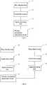
FIG. 4 , thesignal processing unit 13 includes asignal amplifying circuit 131, afiltering circuit 132, and an A/D conversion circuit 133. Thesignal amplifying circuit 131 amplifies the analog signal, thefiltering circuit 132 filters the amplified analog signal to obtain the needed human body physiological signal, and the A/D conversion circuit 133 converts the filtered analog signal to a digital signal. - The
signal amplifying circuit 131 can be connected to the correspondingtensile force sensor 12 for amplifying the electrical signal generated by thetensile force sensor 12 such that the electrical signal can be thereafter filtered. The amplification degree to which the electrical signal is amplified by thesignal amplifying circuit 131 can be determined according to actual requirements. - The
filtering circuit 132 can be connected to thesignal amplifying circuit 131 for filtering the electrical signal amplified by thesignal amplifying circuit 131. Corresponding parameters of thefiltering circuit 132 can be set to filter signals having undesired frequencies and obtain needed electrical signals, for example, to filter the signal having a frequency not in the range from 0.7 Hz to 3 Hz and to obtain the needed heartbeat signal (generally having a frequency ranging from 0.7 Hz to 3 Hz). Thus, corresponding parameters of thefiltering circuit 132 can be set to allow thefiltering circuit 132 to filter undesired electrical signals and obtain needed physiological signals. - The A/
D conversion circuit 133 can be connected to thefiltering circuit 132 for performing the analog-to-digital conversion to the filtered electrical signal. Since the electrical signal generated by thetensile force sensor 12 is generally an analog signal, the filtered electrical signal is correspondingly an analog signal. The A/D conversion circuit 133 is capable of converting the analog signal to a digital signal for allowing for easy operations such as a further process and transmission of the signal. - Referring to
FIG. 5 , in another embodiment of the present disclosure, the above device further includes a wirelessunvarnished transmission circuit 14 for transmitting the digital signal via wireless unvarnished transmission. - In order to improve the convenience of the collection of the human body physiological signal, the collection of the physiological signal can be separated from a further analysis and unified storage of the physiological signal. After the needed physiological signal is collected, the wireless
unvarnished transmission circuit 14 can transmit the physiological signal to a remote device to allow for the further analysis and unified storage of the physiological signal. - The above device further includes a power supply unit (not shown) and a power supply management unit (not shown). The power supply unit is configured for supplying power and the power supply management unit is configured for managing the power supply unit.
- The above power supply unit can be a battery for supplying power to the above device. The device manages the power supply unit via the power supply management unit.
- The above power supply unit can be a connecting component connected to an external power supply for supplying power to the above device. The above device manages the connecting component via the power supply management unit.
- The above wavy physiological signal collecting device converts the human body pressure to an electrical signal and processes the electrical signal via the wavy
flexible body 11, thereby obtaining the human body physiological signal without directly contacting human skin, allowing the physiological signal to be obtained more conveniently. Meanwhile, the obtained physiological signal is transmitted to a remote device by using wireless technology to separate the collection of the signal from the further analysis and unified storage of the signal, which further facilitates the collection of the physiological signal. - Referring to
FIG. 6 , a physiological signal collecting mattress in accordance with an embodiment of the present disclosure is provided. The mattress includes at least two wavy physiological signal collecting devices and a wirelessunvarnished transmission circuit 14. - Each of the wavy physiological signal collecting devices includes a wavy
flexible body 11, atensile force sensor 12, and asignal processing unit 13. The wavy flexible body includes aflexible body panel 111 and a plurality of protrudingflexible bodies 112 each of which is arranged on the flexible body panel 111 (shown inFIG. 3 ) for converting a human pressure applied thereto to a tensile force. Thetensile force sensor 12 is arranged in theflexible body panel 111 for generating an electrical signal according to the tensile force. Thesignal processing unit 13 processes the electrical signal to obtain the corresponding human body physiological signal. The wirelessunvarnished transmission circuit 14 transmits the digital signal via wireless unvarnished transmission. The physiological signal includes a respiration signal, a heartbeat signal, a convulsion signal, and a motion signal, etc. - In order to save cost, the two or more above wavy physiological signal collecting devices can share one wireless
unvarnished transmission circuit 14 for transmitting the digital signal. - The
signal processing units 13 of the above at least two wavy physiological signal collecting devices can respectively obtain different physiological signals which are respectively transmitted via the wirelessunvarnished transmission circuit 14. For example, one of the wavy physiological signal collecting devices can obtain the respiration signal, and the other one can obtain the heartbeat signal. - In the actual manufacture of the above mattress, the wavy
flexible body 11 may be formed as a one-piece body, and theflexible body panel 111 and the protrudingflexible bodies 112 are integrally formed and are separatedly described for easy description in the above disclosure. - Even though information and the advantages of the present embodiments have been set forth in the foregoing description, together with details of the mechanisms and functions of the present embodiments, the disclosure is illustrative only; and that changes may be made in detail, especially in matters of shape, size, and arrangement of parts within the principles of the present embodiments to the full extend indicated by the broad general meaning of the terms in which the appended claims are expressed.
Claims (6)
- A wavy physiological signal collecting device, comprising:a wavy flexible body (11), comprising a flexible body panel (111) and a plurality of protruding flexible bodies (112) each of which is arranged on the flexible body panel (111) for converting a human body pressure applied thereto to a tensile force;a tensile force sensor (12) arranged in the flexible body panel (111) for generating an electrical signal according to the tensile force; anda signal processing unit (13) configured for processing the electrical signal to obtain a corresponding human body physiological signal; wherein the protruding flexible bodies (112) are respectively spacedly arranged on an upper surface and a lower surface of the flexible body panel (111) to form a panel of the wavy flexible body (11), a spacing area (113) is defined between two adjacent protruding flexible bodies (112); each protruding flexible body (112) located on the upper surface corresponds to a spacing area (113) between two adjacent protruding flexible bodies (112) arranged on the lower surface, and each spacing area (113) located on the upper surface corresponds to a protruding flexible body (112) located on the lower surface;each of the protruding flexible bodies (112) are strip shaped and parallel with a width of the elongated flexible body panel (111); anda cross-sectional view of each of the protruding flexible bodies (112) is a curved surface, curved surfaces of the protruding flexible bodies (112) located on the upper surface cooperating with curved surfaces of the protruding flexible bodies (112) located on the lower surface to form a curve similar to a sinusoid symmetrically centered on the flexible body panel (111).
- The device of claim 1, wherein the signal processing unit (13) comprises a signal amplifying circuit (131) for amplifying an analog electrical signal, a filtering circuit (132) for filtering the amplified analog electrical signal to obtain the human body physiological signal, and an A/D conversion circuit (133) for converting the filtered analog electrical signal to a digital signal.
- The device of claim 1 further comprising a wireless unvarnished transmission circuit (14) configured for transmitting the digital signal via wireless unvarnished transmission.
- The device of claim 1 further comprising a power supply unit for supplying power and a power supply management unit for managing the power supply unit.
- The device of claim 4, wherein the power supply unit comprises a battery.
- A physiological signal collecting mattress, comprising at least two wavy physiological signal collecting devices according to any one of claims 1-5 and a wireless unvarnished transmission circuit (14) configured for transmitting the electrical signal via wireless unvarnished transmission.
Applications Claiming Priority (2)
| Application Number | Priority Date | Filing Date | Title |
|---|---|---|---|
| CN2011102556418ACN102319057B (en) | 2011-08-31 | 2011-08-31 | Wavy physiological signal acquisition device and physiological signal acquisition cushion |
| PCT/CN2012/076957WO2013029408A1 (en) | 2011-08-31 | 2012-06-15 | Wave-shaped physiological signal acquisition device and physiological signal acquisition mattress |
Publications (3)
| Publication Number | Publication Date |
|---|---|
| EP2752152A1 EP2752152A1 (en) | 2014-07-09 |
| EP2752152A4 EP2752152A4 (en) | 2015-03-18 |
| EP2752152B1true EP2752152B1 (en) | 2019-05-22 |
Family
ID=45446994
Family Applications (1)
| Application Number | Title | Priority Date | Filing Date |
|---|---|---|---|
| EP12827616.9ANot-in-forceEP2752152B1 (en) | 2011-08-31 | 2012-06-15 | Wave-shaped physiological signal acquisition device and physiological signal acquisition mattress |
Country Status (6)
| Country | Link |
|---|---|
| US (1) | US9138190B2 (en) |
| EP (1) | EP2752152B1 (en) |
| JP (1) | JP5766880B2 (en) |
| KR (1) | KR101591330B1 (en) |
| CN (1) | CN102319057B (en) |
| WO (1) | WO2013029408A1 (en) |
Families Citing this family (11)
| Publication number | Priority date | Publication date | Assignee | Title |
|---|---|---|---|---|
| CN102319057B (en)* | 2011-08-31 | 2013-11-06 | 深圳市视聆科技开发有限公司 | Wavy physiological signal acquisition device and physiological signal acquisition cushion |
| CN102429642B (en)* | 2011-09-26 | 2014-03-05 | 深圳市视聆科技开发有限公司 | Method and system for acquiring physiological information and converter |
| CN104013392A (en)* | 2014-05-09 | 2014-09-03 | 杨松 | Human body physiological signal collecting device and system |
| CN105167750A (en)* | 2015-08-27 | 2015-12-23 | 杨松 | Pressure signal collecting cushion and pillow |
| CN105249928A (en)* | 2015-10-29 | 2016-01-20 | 杨松 | Pillow capable of collecting physiological signal of human body |
| CN106037646A (en)* | 2016-05-23 | 2016-10-26 | 深圳和而泰智能控制股份有限公司 | Physiological signal acquisition device and mattress |
| WO2018098798A1 (en)* | 2016-12-02 | 2018-06-07 | 深圳前海冰寒信息科技有限公司 | Smart pillow |
| CN112741607A (en)* | 2019-10-30 | 2021-05-04 | 北京大学深圳研究生院 | Heart rate recognition device |
| US11696861B1 (en) | 2020-06-15 | 2023-07-11 | Kendrick L. Riley | Crib bedding with temperature gauge |
| US12279999B2 (en) | 2021-01-22 | 2025-04-22 | Hill-Rom Services, Inc. | Wireless configuration and authorization of a wall unit that pairs with a medical device |
| US12186241B2 (en) | 2021-01-22 | 2025-01-07 | Hill-Rom Services, Inc. | Time-based wireless pairing between a medical device and a wall unit |
Family Cites Families (64)
| Publication number | Priority date | Publication date | Assignee | Title |
|---|---|---|---|---|
| US3926177A (en)* | 1972-09-11 | 1975-12-16 | Cavitron Corp | Activity and respiration monitor |
| US3996922A (en)* | 1973-08-17 | 1976-12-14 | Electronic Monitors, Inc. | Flexible force responsive transducer |
| JPS5114054A (en)* | 1974-07-25 | 1976-02-04 | Hitachi Shipbuilding Eng Co | ROODOSERU |
| US4509527A (en)* | 1983-04-08 | 1985-04-09 | Timex Medical Products Corporation | Cardio-respiration transducer |
| DE3442174C2 (en)* | 1984-11-17 | 1993-11-11 | Hanscarl Prof Dr Med Leuner | Method and device for measuring an indicator of a person's state of relaxation |
| ATE58462T1 (en)* | 1985-05-23 | 1990-12-15 | Heinrich Prof Dr Ing Reents | DEVICE FOR MEASURING THE VITAL FUNCTIONS OF A HUMAN, ESPECIALLY AN INFANT. |
| EP0778003A3 (en)* | 1990-03-09 | 1998-09-30 | Matsushita Electric Industrial Co., Ltd. | Presence detecting apparatus |
| US5148706A (en)* | 1991-05-29 | 1992-09-22 | France Bed Co., Ltd. | Apparatus for selecting mattress |
| US5353793A (en)* | 1991-11-25 | 1994-10-11 | Oishi-Kogyo Company | Sensor apparatus |
| US5664270A (en)* | 1994-07-19 | 1997-09-09 | Kinetic Concepts, Inc. | Patient interface system |
| US6778090B2 (en)* | 1996-09-04 | 2004-08-17 | Paul Newham | Modular system for monitoring the presence of a person using a variety of sensing devices |
| US5808552A (en)* | 1996-11-25 | 1998-09-15 | Hill-Rom, Inc. | Patient detection system for a patient-support device |
| JP3820811B2 (en)* | 1999-08-02 | 2006-09-13 | 株式会社デンソー | Respiratory system disease monitoring device |
| US6468234B1 (en)* | 2000-07-14 | 2002-10-22 | The Board Of Trustees Of The Leland Stanford Junior University | SleepSmart |
| JP3477166B2 (en)* | 2000-12-07 | 2003-12-10 | 学校法人慶應義塾 | Monitoring device |
| TWI224964B (en)* | 2002-03-25 | 2004-12-11 | Molten Corp | Detecting device for cause of pressure sores |
| US6917293B2 (en)* | 2002-05-17 | 2005-07-12 | Tactilitics, Inc. | Integral, flexible, electronic patient sensing and monitoring system |
| FI20021145A7 (en)* | 2002-06-13 | 2003-12-14 | Vaerri Alpo | Equipment for measuring vital signs |
| CA2393880A1 (en)* | 2002-07-17 | 2004-01-17 | Tactex Controls Inc. | Bed occupant monitoring system |
| FI116097B (en)* | 2002-08-21 | 2005-09-15 | Heikki Ruotoistenmaeki | Force or pressure sensor and method for its application |
| JP4013195B2 (en)* | 2002-11-07 | 2007-11-28 | 株式会社シービーシステム開発 | Sleep state monitoring device |
| US20040236202A1 (en)* | 2003-05-22 | 2004-11-25 | Burton Steven Angell | Expandable strap for use in electrical impedance tomography |
| JP2005007067A (en)* | 2003-06-20 | 2005-01-13 | Matsushita Electric Ind Co Ltd | Detection device and detection method for bedridden person |
| WO2005006974A1 (en)* | 2003-07-18 | 2005-01-27 | Intelligent Mechatronic Systems Inc. | Occupant heartbeat detection and monitoring system |
| WO2005022692A2 (en)* | 2003-08-21 | 2005-03-10 | Hill-Rom Services, Inc. | Plug and receptacle having wired and wireless coupling |
| JP2005131036A (en)* | 2003-10-29 | 2005-05-26 | Denso Corp | Sensor sheet |
| JP3960298B2 (en)* | 2003-11-19 | 2007-08-15 | 株式会社デンソー | Sleeping and posture detection device |
| US20070118054A1 (en)* | 2005-11-01 | 2007-05-24 | Earlysense Ltd. | Methods and systems for monitoring patients for clinical episodes |
| JP2007535378A (en)* | 2004-04-30 | 2007-12-06 | ヒル−ロム サービシーズ,インコーポレイティド | Patient support |
| US7883478B2 (en)* | 2004-04-30 | 2011-02-08 | Hill-Rom Services, Inc. | Patient support having real time pressure control |
| US20060076103A1 (en)* | 2004-10-08 | 2006-04-13 | Tactex Controls Inc. | Method for manufacturing sensors having wavy elements |
| US20060084855A1 (en)* | 2004-10-20 | 2006-04-20 | Drager Medical Ag & Co. Kgaa | Electrode belt for carrying out electrodiagnostic procedures on the human body |
| CN1602801A (en)* | 2004-11-03 | 2005-04-06 | 天津泰达生物医学工程股份有限公司 | Non-contact palpitation and respiration monitoring technology |
| CN1788654A (en)* | 2004-12-17 | 2006-06-21 | 北京保迈科技有限公司 | Physiological parameter detection pillow |
| US8419660B1 (en)* | 2005-06-03 | 2013-04-16 | Primus Medical, Inc. | Patient monitoring system |
| JP5108776B2 (en)* | 2005-10-11 | 2012-12-26 | コーニンクレッカ フィリップス エレクトロニクス エヌ ヴィ | A system to monitor several different parameters of a patient in bed |
| JP4900650B2 (en)* | 2005-11-17 | 2012-03-21 | アイシン精機株式会社 | Biological information pressure sensor and biological information pressure detection device |
| JP2008110032A (en)* | 2006-10-30 | 2008-05-15 | Aisin Seiki Co Ltd | Biosignal intensity distribution measuring apparatus and biosignal intensity distribution measuring method |
| CN100444785C (en)* | 2006-11-10 | 2008-12-24 | 南京航空航天大学 | Air cushion type automatic monitoring method for human respiration, heartbeat and turning over |
| DE602007011385D1 (en)* | 2007-01-26 | 2011-02-03 | Bag Bizerba Automotive Gmbh | A sensor system and method for determining at least one of an occupant's weight and position |
| US8075499B2 (en)* | 2007-05-18 | 2011-12-13 | Vaidhi Nathan | Abnormal motion detector and monitor |
| JP4925313B2 (en)* | 2007-05-17 | 2012-04-25 | パナソニック株式会社 | Biological signal detection device |
| US20090062693A1 (en)* | 2007-08-29 | 2009-03-05 | Lancastria Limited | System for determining individual user anthropometric characteristics related to mattress preference |
| JP5164529B2 (en)* | 2007-11-08 | 2013-03-21 | 昭和電工株式会社 | Biological information measurement sensor |
| US8570175B2 (en)* | 2007-11-26 | 2013-10-29 | Gil Goel Rahimi | Securely attachable monitoring device |
| JP2009136477A (en)* | 2007-12-06 | 2009-06-25 | Panasonic Corp | Biological signal detection device |
| US20090287120A1 (en)* | 2007-12-18 | 2009-11-19 | Searete Llc, A Limited Liability Corporation Of The State Of Delaware | Circulatory monitoring systems and methods |
| JP2009172115A (en)* | 2008-01-24 | 2009-08-06 | Panasonic Corp | Pressure-sensitive device and biological signal detection device using the same |
| EP2329769B1 (en)* | 2008-08-19 | 2015-03-25 | Delta Tooling Co., Ltd. | Biometric signal measuring device and organism condition analyzing system |
| CA2775250C (en)* | 2008-10-24 | 2013-03-26 | Elmedex Ltd. | Monitoring system for pressure sore prevention |
| US8444558B2 (en)* | 2009-01-07 | 2013-05-21 | Bam Labs, Inc. | Apparatus for monitoring vital signs having fluid bladder beneath padding |
| US8287452B2 (en)* | 2009-01-07 | 2012-10-16 | Bam Labs, Inc. | Apparatus for monitoring vital signs of an emergency victim |
| FR2940904B1 (en)* | 2009-01-13 | 2012-08-31 | Urgo Laboratoires | INTERFACE PRESSURE MEASURING SYSTEM |
| JP2012518220A (en)* | 2009-02-13 | 2012-08-09 | コーニンクレッカ フィリップス エレクトロニクス エヌ ヴィ | Bed monitoring system |
| US20100268121A1 (en)* | 2009-03-18 | 2010-10-21 | Kilborn John C | Active support surface |
| CN101908408B (en)* | 2009-06-02 | 2011-09-14 | 张政波 | Inductor for respiratory volume kinescope |
| US8752220B2 (en)* | 2009-07-10 | 2014-06-17 | Hill-Rom Services, Inc. | Systems for patient support, monitoring and treatment |
| JP5704651B2 (en)* | 2009-10-14 | 2015-04-22 | 株式会社デルタツーリング | Biological state estimation device, biological state estimation system, and computer program |
| US8393229B2 (en)* | 2010-02-24 | 2013-03-12 | The Hong Kong Research Institute Of Textiles And Apparel Limited | Soft pressure sensing device |
| US8672842B2 (en)* | 2010-08-24 | 2014-03-18 | Evacusled Inc. | Smart mattress |
| CN202235311U (en)* | 2011-08-31 | 2012-05-30 | 深圳市视聆科技开发有限公司 | Non-contact sensor |
| CN102370463A (en)* | 2011-08-31 | 2012-03-14 | 深圳市视聆科技开发有限公司 | Physiological signal non-contact acquisition method and non-contact sensor |
| CN202235312U (en)* | 2011-08-31 | 2012-05-30 | 深圳市视聆科技开发有限公司 | Wave-shaped physiological signal acquisition device and physiological signal acquisition mattress |
| CN102319057B (en)* | 2011-08-31 | 2013-11-06 | 深圳市视聆科技开发有限公司 | Wavy physiological signal acquisition device and physiological signal acquisition cushion |
- 2011
- 2011-08-31CNCN2011102556418Apatent/CN102319057B/ennot_activeExpired - Fee Related
- 2012
- 2012-06-15JPJP2014527470Apatent/JP5766880B2/ennot_activeExpired - Fee Related
- 2012-06-15EPEP12827616.9Apatent/EP2752152B1/ennot_activeNot-in-force
- 2012-06-15KRKR1020147005554Apatent/KR101591330B1/ennot_activeExpired - Fee Related
- 2012-06-15WOPCT/CN2012/076957patent/WO2013029408A1/enactiveApplication Filing
- 2012-06-15USUS14/241,085patent/US9138190B2/ennot_activeExpired - Fee Related
Non-Patent Citations (1)
| Title |
|---|
| None* |
Also Published As
| Publication number | Publication date |
|---|---|
| CN102319057B (en) | 2013-11-06 |
| JP2014529448A (en) | 2014-11-13 |
| JP5766880B2 (en) | 2015-08-19 |
| KR101591330B1 (en) | 2016-02-03 |
| US20140213877A1 (en) | 2014-07-31 |
| US9138190B2 (en) | 2015-09-22 |
| EP2752152A1 (en) | 2014-07-09 |
| EP2752152A4 (en) | 2015-03-18 |
| KR20140050706A (en) | 2014-04-29 |
| WO2013029408A1 (en) | 2013-03-07 |
| CN102319057A (en) | 2012-01-18 |
Similar Documents
| Publication | Publication Date | Title |
|---|---|---|
| EP2752152B1 (en) | Wave-shaped physiological signal acquisition device and physiological signal acquisition mattress | |
| KR102687254B1 (en) | Sleep state measurement device and method, phase coherence calculation device, biological vibration signal measurement device, stress state measurement device, sleep state measurement device, and heart rate waveform extraction method | |
| KR101706546B1 (en) | Personal biosensor accessory attachment | |
| CN103622671B (en) | Noncontact physiology or periodically force signals harvester and mat | |
| JP2005315831A (en) | Electrostatic capacitance type pressure sensor, and heart beat/respiration measuring instrument using the same | |
| US20150201856A1 (en) | Electrode and measuring device for acquiring biomedical vital parameters | |
| CN206166902U (en) | Flexible intelligent fabric sensor, intelligent mattress and monitoring system thereof | |
| US10376216B2 (en) | Device for contactless monitoring of patient's vital signs | |
| CN102415879A (en) | Sleep monitoring device based on piezoelectric film sensor | |
| WO2007074800A1 (en) | Sheet for measuring biometric information | |
| US20090137892A1 (en) | Skin sensor device | |
| CN103054571B (en) | Portable electrocardio and sleep respiration monitoring system | |
| CN106236015A (en) | Flexible intelligent fabric sensor and manufacture method, intelligence mattress and monitoring system | |
| US20110071412A1 (en) | Belt Type Bio-Signal Detecting Device | |
| KR20190089353A (en) | System for measuring bio signal usingmulti channel piezoelectric sensor of film | |
| WO2019106580A1 (en) | Tattoo biosensor and health monitoring system | |
| CN212438589U (en) | Sleep monitoring device and sleep monitoring home textile | |
| CN102631197B (en) | Induction pad | |
| CN211270685U (en) | Sleep monitoring device | |
| CN209826674U (en) | Sleep monitoring device and electronic equipment | |
| Hyun et al. | Patch type integrated sensor system for measuring electrical and mechanical cardiac activities | |
| CN214128522U (en) | Sleep monitoring health sensor | |
| WO2017201940A1 (en) | Physiological signal collection apparatus and mattress | |
| CN204500644U (en) | A kind of sleep detection system and intelligent pillow | |
| CN207168488U (en) | A kind of monitoring system |
Legal Events
| Date | Code | Title | Description |
|---|---|---|---|
| PUAI | Public reference made under article 153(3) epc to a published international application that has entered the european phase | Free format text:ORIGINAL CODE: 0009012 | |
| 17P | Request for examination filed | Effective date:20140328 | |
| AK | Designated contracting states | Kind code of ref document:A1 Designated state(s):AL AT BE BG CH CY CZ DE DK EE ES FI FR GB GR HR HU IE IS IT LI LT LU LV MC MK MT NL NO PL PT RO RS SE SI SK SM TR | |
| DAX | Request for extension of the european patent (deleted) | ||
| A4 | Supplementary search report drawn up and despatched | Effective date:20150216 | |
| RIC1 | Information provided on ipc code assigned before grant | Ipc:A61B 5/02 20060101ALI20150210BHEP Ipc:A61B 5/08 20060101ALI20150210BHEP Ipc:A61B 5/00 20060101AFI20150210BHEP Ipc:A61B 5/11 20060101ALI20150210BHEP | |
| 17Q | First examination report despatched | Effective date:20160331 | |
| STAA | Information on the status of an ep patent application or granted ep patent | Free format text:STATUS: EXAMINATION IS IN PROGRESS | |
| RAP1 | Party data changed (applicant data changed or rights of an application transferred) | Owner name:YANG, SONG | |
| REG | Reference to a national code | Ref country code:DE Ref legal event code:R079 Ref document number:602012060449 Country of ref document:DE Free format text:PREVIOUS MAIN CLASS: A61B0005000000 Ipc:A61B0005024000 | |
| GRAP | Despatch of communication of intention to grant a patent | Free format text:ORIGINAL CODE: EPIDOSNIGR1 | |
| STAA | Information on the status of an ep patent application or granted ep patent | Free format text:STATUS: GRANT OF PATENT IS INTENDED | |
| RIC1 | Information provided on ipc code assigned before grant | Ipc:A61B 5/11 20060101ALI20181121BHEP Ipc:A61B 5/00 20060101ALI20181121BHEP Ipc:A61B 5/024 20060101AFI20181121BHEP Ipc:A61B 5/08 20060101ALI20181121BHEP | |
| INTG | Intention to grant announced | Effective date:20181207 | |
| GRAS | Grant fee paid | Free format text:ORIGINAL CODE: EPIDOSNIGR3 | |
| GRAA | (expected) grant | Free format text:ORIGINAL CODE: 0009210 | |
| STAA | Information on the status of an ep patent application or granted ep patent | Free format text:STATUS: THE PATENT HAS BEEN GRANTED | |
| AK | Designated contracting states | Kind code of ref document:B1 Designated state(s):AL AT BE BG CH CY CZ DE DK EE ES FI FR GB GR HR HU IE IS IT LI LT LU LV MC MK MT NL NO PL PT RO RS SE SI SK SM TR | |
| REG | Reference to a national code | Ref country code:GB Ref legal event code:FG4D | |
| REG | Reference to a national code | Ref country code:CH Ref legal event code:EP | |
| REG | Reference to a national code | Ref country code:IE Ref legal event code:FG4D | |
| REG | Reference to a national code | Ref country code:DE Ref legal event code:R096 Ref document number:602012060449 Country of ref document:DE | |
| REG | Reference to a national code | Ref country code:AT Ref legal event code:REF Ref document number:1135092 Country of ref document:AT Kind code of ref document:T Effective date:20190615 | |
| REG | Reference to a national code | Ref country code:NL Ref legal event code:MP Effective date:20190522 | |
| REG | Reference to a national code | Ref country code:LT Ref legal event code:MG4D | |
| PG25 | Lapsed in a contracting state [announced via postgrant information from national office to epo] | Ref country code:AL Free format text:LAPSE BECAUSE OF FAILURE TO SUBMIT A TRANSLATION OF THE DESCRIPTION OR TO PAY THE FEE WITHIN THE PRESCRIBED TIME-LIMIT Effective date:20190522 Ref country code:PT Free format text:LAPSE BECAUSE OF FAILURE TO SUBMIT A TRANSLATION OF THE DESCRIPTION OR TO PAY THE FEE WITHIN THE PRESCRIBED TIME-LIMIT Effective date:20190922 Ref country code:NL Free format text:LAPSE BECAUSE OF FAILURE TO SUBMIT A TRANSLATION OF THE DESCRIPTION OR TO PAY THE FEE WITHIN THE PRESCRIBED TIME-LIMIT Effective date:20190522 Ref country code:LT Free format text:LAPSE BECAUSE OF FAILURE TO SUBMIT A TRANSLATION OF THE DESCRIPTION OR TO PAY THE FEE WITHIN THE PRESCRIBED TIME-LIMIT Effective date:20190522 Ref country code:ES Free format text:LAPSE BECAUSE OF FAILURE TO SUBMIT A TRANSLATION OF THE DESCRIPTION OR TO PAY THE FEE WITHIN THE PRESCRIBED TIME-LIMIT Effective date:20190522 Ref country code:HR Free format text:LAPSE BECAUSE OF FAILURE TO SUBMIT A TRANSLATION OF THE DESCRIPTION OR TO PAY THE FEE WITHIN THE PRESCRIBED TIME-LIMIT Effective date:20190522 Ref country code:NO Free format text:LAPSE BECAUSE OF FAILURE TO SUBMIT A TRANSLATION OF THE DESCRIPTION OR TO PAY THE FEE WITHIN THE PRESCRIBED TIME-LIMIT Effective date:20190822 Ref country code:SE Free format text:LAPSE BECAUSE OF FAILURE TO SUBMIT A TRANSLATION OF THE DESCRIPTION OR TO PAY THE FEE WITHIN THE PRESCRIBED TIME-LIMIT Effective date:20190522 Ref country code:FI Free format text:LAPSE BECAUSE OF FAILURE TO SUBMIT A TRANSLATION OF THE DESCRIPTION OR TO PAY THE FEE WITHIN THE PRESCRIBED TIME-LIMIT Effective date:20190522 | |
| PG25 | Lapsed in a contracting state [announced via postgrant information from national office to epo] | Ref country code:RS Free format text:LAPSE BECAUSE OF FAILURE TO SUBMIT A TRANSLATION OF THE DESCRIPTION OR TO PAY THE FEE WITHIN THE PRESCRIBED TIME-LIMIT Effective date:20190522 Ref country code:GR Free format text:LAPSE BECAUSE OF FAILURE TO SUBMIT A TRANSLATION OF THE DESCRIPTION OR TO PAY THE FEE WITHIN THE PRESCRIBED TIME-LIMIT Effective date:20190823 Ref country code:LV Free format text:LAPSE BECAUSE OF FAILURE TO SUBMIT A TRANSLATION OF THE DESCRIPTION OR TO PAY THE FEE WITHIN THE PRESCRIBED TIME-LIMIT Effective date:20190522 Ref country code:BG Free format text:LAPSE BECAUSE OF FAILURE TO SUBMIT A TRANSLATION OF THE DESCRIPTION OR TO PAY THE FEE WITHIN THE PRESCRIBED TIME-LIMIT Effective date:20190822 | |
| REG | Reference to a national code | Ref country code:AT Ref legal event code:MK05 Ref document number:1135092 Country of ref document:AT Kind code of ref document:T Effective date:20190522 | |
| PG25 | Lapsed in a contracting state [announced via postgrant information from national office to epo] | Ref country code:SK Free format text:LAPSE BECAUSE OF FAILURE TO SUBMIT A TRANSLATION OF THE DESCRIPTION OR TO PAY THE FEE WITHIN THE PRESCRIBED TIME-LIMIT Effective date:20190522 Ref country code:RO Free format text:LAPSE BECAUSE OF FAILURE TO SUBMIT A TRANSLATION OF THE DESCRIPTION OR TO PAY THE FEE WITHIN THE PRESCRIBED TIME-LIMIT Effective date:20190522 Ref country code:CZ Free format text:LAPSE BECAUSE OF FAILURE TO SUBMIT A TRANSLATION OF THE DESCRIPTION OR TO PAY THE FEE WITHIN THE PRESCRIBED TIME-LIMIT Effective date:20190522 Ref country code:DK Free format text:LAPSE BECAUSE OF FAILURE TO SUBMIT A TRANSLATION OF THE DESCRIPTION OR TO PAY THE FEE WITHIN THE PRESCRIBED TIME-LIMIT Effective date:20190522 Ref country code:AT Free format text:LAPSE BECAUSE OF FAILURE TO SUBMIT A TRANSLATION OF THE DESCRIPTION OR TO PAY THE FEE WITHIN THE PRESCRIBED TIME-LIMIT Effective date:20190522 Ref country code:EE Free format text:LAPSE BECAUSE OF FAILURE TO SUBMIT A TRANSLATION OF THE DESCRIPTION OR TO PAY THE FEE WITHIN THE PRESCRIBED TIME-LIMIT Effective date:20190522 | |
| REG | Reference to a national code | Ref country code:CH Ref legal event code:PL | |
| REG | Reference to a national code | Ref country code:DE Ref legal event code:R097 Ref document number:602012060449 Country of ref document:DE | |
| PG25 | Lapsed in a contracting state [announced via postgrant information from national office to epo] | Ref country code:MC Free format text:LAPSE BECAUSE OF FAILURE TO SUBMIT A TRANSLATION OF THE DESCRIPTION OR TO PAY THE FEE WITHIN THE PRESCRIBED TIME-LIMIT Effective date:20190522 Ref country code:SM Free format text:LAPSE BECAUSE OF FAILURE TO SUBMIT A TRANSLATION OF THE DESCRIPTION OR TO PAY THE FEE WITHIN THE PRESCRIBED TIME-LIMIT Effective date:20190522 Ref country code:IT Free format text:LAPSE BECAUSE OF FAILURE TO SUBMIT A TRANSLATION OF THE DESCRIPTION OR TO PAY THE FEE WITHIN THE PRESCRIBED TIME-LIMIT Effective date:20190522 | |
| PLBE | No opposition filed within time limit | Free format text:ORIGINAL CODE: 0009261 | |
| REG | Reference to a national code | Ref country code:BE Ref legal event code:MM Effective date:20190630 | |
| STAA | Information on the status of an ep patent application or granted ep patent | Free format text:STATUS: NO OPPOSITION FILED WITHIN TIME LIMIT | |
| PG25 | Lapsed in a contracting state [announced via postgrant information from national office to epo] | Ref country code:TR Free format text:LAPSE BECAUSE OF FAILURE TO SUBMIT A TRANSLATION OF THE DESCRIPTION OR TO PAY THE FEE WITHIN THE PRESCRIBED TIME-LIMIT Effective date:20190522 | |
| 26N | No opposition filed | Effective date:20200225 | |
| PG25 | Lapsed in a contracting state [announced via postgrant information from national office to epo] | Ref country code:IE Free format text:LAPSE BECAUSE OF NON-PAYMENT OF DUE FEES Effective date:20190615 Ref country code:PL Free format text:LAPSE BECAUSE OF FAILURE TO SUBMIT A TRANSLATION OF THE DESCRIPTION OR TO PAY THE FEE WITHIN THE PRESCRIBED TIME-LIMIT Effective date:20190522 | |
| PG25 | Lapsed in a contracting state [announced via postgrant information from national office to epo] | Ref country code:CH Free format text:LAPSE BECAUSE OF NON-PAYMENT OF DUE FEES Effective date:20190630 Ref country code:BE Free format text:LAPSE BECAUSE OF NON-PAYMENT OF DUE FEES Effective date:20190630 Ref country code:LI Free format text:LAPSE BECAUSE OF NON-PAYMENT OF DUE FEES Effective date:20190630 Ref country code:SI Free format text:LAPSE BECAUSE OF FAILURE TO SUBMIT A TRANSLATION OF THE DESCRIPTION OR TO PAY THE FEE WITHIN THE PRESCRIBED TIME-LIMIT Effective date:20190522 Ref country code:LU Free format text:LAPSE BECAUSE OF NON-PAYMENT OF DUE FEES Effective date:20190615 | |
| PG25 | Lapsed in a contracting state [announced via postgrant information from national office to epo] | Ref country code:CY Free format text:LAPSE BECAUSE OF FAILURE TO SUBMIT A TRANSLATION OF THE DESCRIPTION OR TO PAY THE FEE WITHIN THE PRESCRIBED TIME-LIMIT Effective date:20190522 | |
| PG25 | Lapsed in a contracting state [announced via postgrant information from national office to epo] | Ref country code:IS Free format text:LAPSE BECAUSE OF FAILURE TO SUBMIT A TRANSLATION OF THE DESCRIPTION OR TO PAY THE FEE WITHIN THE PRESCRIBED TIME-LIMIT Effective date:20190922 | |
| PG25 | Lapsed in a contracting state [announced via postgrant information from national office to epo] | Ref country code:MT Free format text:LAPSE BECAUSE OF FAILURE TO SUBMIT A TRANSLATION OF THE DESCRIPTION OR TO PAY THE FEE WITHIN THE PRESCRIBED TIME-LIMIT Effective date:20190522 Ref country code:HU Free format text:LAPSE BECAUSE OF FAILURE TO SUBMIT A TRANSLATION OF THE DESCRIPTION OR TO PAY THE FEE WITHIN THE PRESCRIBED TIME-LIMIT; INVALID AB INITIO Effective date:20120615 | |
| PGFP | Annual fee paid to national office [announced via postgrant information from national office to epo] | Ref country code:FR Payment date:20210629 Year of fee payment:10 | |
| PGFP | Annual fee paid to national office [announced via postgrant information from national office to epo] | Ref country code:GB Payment date:20210629 Year of fee payment:10 | |
| PGFP | Annual fee paid to national office [announced via postgrant information from national office to epo] | Ref country code:DE Payment date:20210827 Year of fee payment:10 | |
| PG25 | Lapsed in a contracting state [announced via postgrant information from national office to epo] | Ref country code:MK Free format text:LAPSE BECAUSE OF FAILURE TO SUBMIT A TRANSLATION OF THE DESCRIPTION OR TO PAY THE FEE WITHIN THE PRESCRIBED TIME-LIMIT Effective date:20190522 | |
| REG | Reference to a national code | Ref country code:DE Ref legal event code:R119 Ref document number:602012060449 Country of ref document:DE | |
| GBPC | Gb: european patent ceased through non-payment of renewal fee | Effective date:20220615 | |
| PG25 | Lapsed in a contracting state [announced via postgrant information from national office to epo] | Ref country code:FR Free format text:LAPSE BECAUSE OF NON-PAYMENT OF DUE FEES Effective date:20220630 | |
| PG25 | Lapsed in a contracting state [announced via postgrant information from national office to epo] | Ref country code:GB Free format text:LAPSE BECAUSE OF NON-PAYMENT OF DUE FEES Effective date:20220615 Ref country code:DE Free format text:LAPSE BECAUSE OF NON-PAYMENT OF DUE FEES Effective date:20230103 |