EP2750757B1 - System and method for the remote programming of mri settings of an implantable medical device - Google Patents
System and method for the remote programming of mri settings of an implantable medical deviceDownload PDFInfo
- Publication number
- EP2750757B1 EP2750757B1EP12759302.8AEP12759302AEP2750757B1EP 2750757 B1EP2750757 B1EP 2750757B1EP 12759302 AEP12759302 AEP 12759302AEP 2750757 B1EP2750757 B1EP 2750757B1
- Authority
- EP
- European Patent Office
- Prior art keywords
- mri
- imd
- programmer
- settings
- patient
- Prior art date
- Legal status (The legal status is an assumption and is not a legal conclusion. Google has not performed a legal analysis and makes no representation as to the accuracy of the status listed.)
- Active
Links
Images


Classifications
- A—HUMAN NECESSITIES
- A61—MEDICAL OR VETERINARY SCIENCE; HYGIENE
- A61N—ELECTROTHERAPY; MAGNETOTHERAPY; RADIATION THERAPY; ULTRASOUND THERAPY
- A61N1/00—Electrotherapy; Circuits therefor
- A61N1/18—Applying electric currents by contact electrodes
- A61N1/32—Applying electric currents by contact electrodes alternating or intermittent currents
- A61N1/36—Applying electric currents by contact electrodes alternating or intermittent currents for stimulation
- A61N1/362—Heart stimulators
- A61N1/37—Monitoring; Protecting
- A61N1/3718—Monitoring of or protection against external electromagnetic fields or currents
- A—HUMAN NECESSITIES
- A61—MEDICAL OR VETERINARY SCIENCE; HYGIENE
- A61N—ELECTROTHERAPY; MAGNETOTHERAPY; RADIATION THERAPY; ULTRASOUND THERAPY
- A61N1/00—Electrotherapy; Circuits therefor
- A61N1/18—Applying electric currents by contact electrodes
- A61N1/32—Applying electric currents by contact electrodes alternating or intermittent currents
- A61N1/36—Applying electric currents by contact electrodes alternating or intermittent currents for stimulation
- A61N1/372—Arrangements in connection with the implantation of stimulators
- A61N1/37211—Means for communicating with stimulators
- A61N1/37235—Aspects of the external programmer
- A—HUMAN NECESSITIES
- A61—MEDICAL OR VETERINARY SCIENCE; HYGIENE
- A61N—ELECTROTHERAPY; MAGNETOTHERAPY; RADIATION THERAPY; ULTRASOUND THERAPY
- A61N1/00—Electrotherapy; Circuits therefor
- A61N1/18—Applying electric currents by contact electrodes
- A61N1/32—Applying electric currents by contact electrodes alternating or intermittent currents
- A61N1/36—Applying electric currents by contact electrodes alternating or intermittent currents for stimulation
- A61N1/372—Arrangements in connection with the implantation of stimulators
- A61N1/37211—Means for communicating with stimulators
- A61N1/37252—Details of algorithms or data aspects of communication system, e.g. handshaking, transmitting specific data or segmenting data
- A61N1/37282—Details of algorithms or data aspects of communication system, e.g. handshaking, transmitting specific data or segmenting data characterised by communication with experts in remote locations using a network
Definitions
- the inventionrelates to implantable medical devices, such as cardiac rhythm management devices, and more particularly, to methods and systems for programming such devices in advance of a magnetic resonance imaging (MRI) procedure.
- MRImagnetic resonance imaging
- cardiac rhythm management devicessuch as a pacemaker or implantable defibrillator.
- Cardiac rhythm management (CRM) devicesare used to provide medical therapy to patients who have a disorder related to cardiac rhythm, such as bradycardia or tachycardia.
- Magnetic resonance imagingis a method of visualizing body tissues of a patient, primarily to identify pathological conditions or to visualize physiological structure for purposes of medical diagnosis and therapy.
- MRIrelies on subjecting the body tissue of interest to a very strong uniform magnetic field, up to about 30,000 gauss, as well as a moderate strength but variable magnetic field of around 200 gauss.
- RFradio frequency
- Hydrogen atoms within the body tissuehave a magnetic moment and tend to line up with the direction of the applied magnetic fields. Some of these hydrogen atoms will align facing one direction and others will align facing an opposite direction, such that most of the hydrogen atoms facing in alternating directions will tend to cancel each other out.
- the applied RF pulsetends to cause the unbalanced hydrogen protons to spin, or resonate, in a particular direction and at a particular frequency.
- the spinning hydrogen protonsrevert to their earlier, aligned position, and release their excess energy.
- the RF coil of the MRI machineis capable of detecting this emitted energy and transmitting a corresponding signal to a processor that transforms the signal to an image of the body tissue. Because different tissues have different characteristic responses to the application of the RF pulse in the presence of the magnetic fields, these differences can be utilized to prepare an image showing areas of contrasting tissue types.
- MRI techniqueshave proven to be very effective at diagnosing certain medical conditions and allowing for patients to receive timely, appropriate medical therapy.
- the electromagnetic radiation produced by the MRI systemmay interfere with the operation of an IMD.
- the presence of strong magnetic fields and RF energy during an MRI scanmay prevent the charging of a high voltage capacitor within the cardiac device, which can affect the ability of the cardiac device to deliver electrical shocks to the patient when an event such as a tachyarrhythmia occurs.
- the RF energy and/or time varying gradient fieldsmay prevent the sensing and detection of tachyarrhythmias by cardiac devices.
- the MRI systemmay also affect other types of implantable medical devices (IMDs).
- IMDsprovide for a method of operating an IMD in the presence of an MRI environment using particular MRI settings for the IMD.
- Examples of patents and patent publications that describe such methods and options for MRI settings for an IMDinclude U.S. Published Patent Application No. 2010-0087892A1, Stubbs et al. ; U.S. Published Patent Application No. 2010-0106215A1, Stubbs et al ; U.S. Published Patent Application No. 2010-0211123A1, Stubbs et al ; U.S. Published Patent Application No. 2008-0221638A1, Wedan et al ; U.S. Patent No. 7,853,318, Wedan and U.S. Patent No. 7,873,412, Wedan .
- US 2010/0137945 A1discloses a technique including transmitting information regarding MRI compatibility of an implanted medical device.
- the present inventionrelates to a system as set out in claim 1 and a method as set out in claim 13. Other embodiments are described in the dependent claims.
- the inventionrelates to implantable medical devices such as cardiac rhythm management devices, and more particularly, to methods and systems for efficiently programming such devices. Still more particularly, embodiments of the invention relate to efficiently programming cardiac rhythm management devices in advance of a magnetic resonance imaging (MRI) procedure.
- MRImagnetic resonance imaging
- MRImagnetic resonance imaging
- many IMDsare capable of MRI settings that reduce the risks associated with an MRI.
- Another concernis that patients with IMDs need to be evaluated by a knowledgeable health care professional before permitting an MRI procedure.
- a health care professionalwho is trained in IMD programming and in evaluating patients provides MRI settings for a particular IMD after evaluating the patient having the IMD.
- the MRI settingsare provided to an external storage media where the MRI settings are stored.
- the MRI settingsare stored on the external storage media in advance of the scheduled time for the MRI procedure.
- the external storage mediacan be a network server that is connected to the programmer used by the health care professional by the Internet or by another network.
- the external storage mediacan also be a portable storage device, such as a magnetic card or jump drive.
- the MRI prescriptioncan also include computer readable instructions to carry out the programming of the MRI settings on the IMD.
- the MRI prescriptionalso includes identity data to identify the health care professional who evaluated the patient and provided the MRI settings.
- the MRI prescriptionalso includes a timer value indicating a length of time during which the MRI settings will be active. After the expiration of the timer value, the IMD will go out of the MRI mode and the parameter settings will revert back to the pre-MRI settings, in one embodiment.
- the MRI prescriptionalso includes, in some embodiments, one or more of an indication of which chambers are paced, an MRI pacing mode, an MRI pace amplitude, an MRI pace rate, and an MRI pulse width.
- an indication of which chambers are pacedan MRI pacing mode
- an MRI pace amplitudean MRI pace rate
- an MRI pulse widthan MRI pulse width
- the concepts described hereinare not limited to these particular settings or to cardiac devices.
- different parameter valuesare provided for a cardiac device.
- parameter valuesare provided for other IMDs.
- the health care professionalalso enters a timeframe over which the MRI prescription will be valid, in one embodiment. After the timeframe has passed, the MRI prescription cannot be retrieved from the storage media. The patient will be reevaluated and a new MRI prescription will be created.
- an MRI technicianuses a programmer device to access identity data on the IMD which uniquely identifies the particular IMD or particular patient.
- the MRI technicianfurther uses the programmer to communicate with the external storage media to retrieve the previously-stored MRI prescription, including MRI settings, and program the IMD using the MRI settings.
- the existence of a previously-stored valid MRI prescriptionindicates that the patient has been evaluated and cleared for an MRI procedure.
- the programmer used by the MRI technicianis able to communicate with the external storage media to retrieve the MRI settings that are associated with the IMD.
- a first communication module within the programmercarries out the communication with the external storage media.
- the programmeris also able to communicate with the IMD to determine the identity of the IMD or the patient and program the IMD with the MRI settings.
- the communication with the IMDis carried out by a device communication module of the programmer.
- the device communication modulemay communicate inductively, by radio frequency or other methods.
- the first communication modulecan communicate with the external storage media over a pervasive wireless network, over a wired network, or by other means.
- the programmerfurther includes a power source configured to supply power for components of the programmer. In one embodiment of such a system, the programmer has a portable housing configuration and the power supply is included in the housing.
- FIG. 1is a schematic view of one embodiment of a system for remote programming of an IMD with MRI settings.
- an IMD 110is shown implanted in a patient 112.
- the patient 112is shown present in a device clinic 114 and, at a later time, will also be present in an MRI clinic 115.
- IMDs 110include, without limitation, a cardiac device, a pacemaker, a defibrillator, a cardiac resynchronization therapy (CRT) device, an insulin pump, a loop recorder, a neurostimulator, a physiological sensor, a glucose meter or a combination of such devices.
- CTRcardiac resynchronization therapy
- the systemalso includes an device clinic programmer 116 or other external device that communicates wireless signals with the IMD 110, such as by using radio frequency (RF) or other telemetry signals.
- the device clinic programmer 116communicates inductively using a wand 120.
- the device clinic programmer 116can also communicate with an external storage media.
- the communication with the external storage mediaallows storage of MRI settings that are entered using the device clinic programmer 116.
- the external storage mediais a part of a server 132. It is also possible for the external storage media to be a portable storage device, such as a flash drive or magnetic card.
- serverand “prescription server” will be used to describe the storage location of the MRI settings in a number of embodiments described herein, including the embodiments of FIG. 1 , it will be understood that it is also possible for the MRI settings to be stored on an external storage media different than a server.
- the device clinic programmer 116includes a graphical display 118 and user input devices such as in some embodiments a keyboard and a mouse.
- a health care professional 128can use the device clinic programmer to program IMDs, record data from IMDs, allow monitoring of the implanted device and upload information to a server 132.
- the health care professional 128can evaluate the patient 112, the type of IMD 110 and other factors and can determine the patient eligibility for an MRI procedure.
- the device clinic programmermay have the shape of a laptop computer, a desktop computer, a tablet computer, a smart phone or another configuration.
- the device clinic programmer 116is depicted in a ruggedized laptop computer configuration.
- the device clinic programmer 116can also be referred to as a user interface or an external interface device.
- the device clinic programmer 116is in communication with a server, which can be referred to as a prescription server 132.
- the communication link between the programmer 116 and the server 132may be via phone lines, a wired network, the Internet 130, or any other data connection, such as a pervasive wireless network.
- the device clinic programmer 116can also be used when it is not in communication with an IMD device, but is only in communication with the server 132.
- the device clinic programmer 116can also be used when it is not in communication with the server 132, but is only in communication with an IMD.
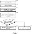
- FIG. 2sets forth one embodiment of steps for how a patient with an IMD may be evaluated for a possible MRI procedure.
- step 210the patient undergoes an IMD implantation procedure. Later, possibly years later, the patient is identified as a candidate for an MRI procedure in step 212.
- the patientmay be rejected for the MRI due to the presence of the IMD in step 214.
- This stepcauses the patient to be directed to a health care professional having training related to the IMD for review of IMD details, patient condition and safety concerns related to the MRI procedure at step 216.
- this review by a health care professional 128can take place in a device clinic 114 using the device clinic programmer 116 and a connection to the prescription server 132.
- the health care professionaldetermines whether an MRI procedure would be safe for the patient at step 218. If no, the MRI is not permitted at step 220. If yes, the health care professional generates an MRI prescription including MRI settings and causes those to be stored on the server 132. At this point in time in the process, the MRI settings have not yet been programmed into the IMD. Instead, the MRI settings have been stored on the server 132 for later retrieval at the time of the MRI procedure.
- Particular steps that are taken by the device clinic programmer in some embodimentsinclude interrogating the IMD to determine its status and download diagnostic and therapeutic information and displaying to the health care professional an MRI checklist.
- the MRI checklistis formulated to assist the professional with the assessment of whether or not an MRI should be permitted for the patient. If the health care professional determines that an MRI should be permitted, the device clinic programmer presents an MRI prescription form to the professional.
- the MRI prescription form 1000 shown in FIG. 10is formatted for display on a smart phone-type display.
- the professionaluses the MRI prescription form to enter parameter data for the MRI settings. Some of the data entered are numerical values for particular parameter settings, such as the MRI timer and MRI pulse width.
- the MRI prescription formalso includes, in some embodiments, one or more of an indication of which chambers are paced, an MRI pacing mode, an MRI pace amplitude, an MRI pace rate, an MRI settings timer and a selection for a validity timeframe. Some of the selections can be made on the portion of the form shown in FIG.
- the programmerAfter entry of the data into the MRI prescription form, the programmer performs a range checking step in some embodiments.
- the range checking stepcompares the entered values against expectations regarding these values, to determine if the values are correct for the particular situation. In one example, the programmer checks to see that the timer value is a positive number and that it falls in a range of 1 to 24 hours. Other numerical values for the MRI settings are also compared to an expected range in some embodiments.
- the device clinic programmercompiles the completed MRI prescription form into a structured text-based software program that can be executed at the MRI clinic to change the IMD settings.
- the MRI prescription informationis stored until retrieved.
- the MRI prescriptionis uniquely tagged with identify data, such as an identification number, that uniquely identifies the patient, the particular IMD or both.
- identify datasuch as an identification number, that uniquely identifies the patient, the particular IMD or both.
- the unique identity data stored on the IMDis a device serial number.
- a second server 133 or additional serversare in communication with the device clinic programmer 116 and with the MRI clinic programmer 140.
- the second server 133can be a care server that allows clinicians to log in and view the details of what is happening with their patient's IMD performance or history.
- One example of such a systemis the LATITUDE ® Patient Management System that is designed for use with certain compatible pulse generators manufactured by Boston Scientific Corporation. It is also possible for the system to be connected to other servers, such as servers that store electronic medical records (EMRs) of patients. It is also possible for the programmer to communicate with a single server for multiple purposes, such as for retrieving prescriptions and for patient care, for patient care and EMRs, or for EMRs and retrieving prescriptions.
- EMRselectronic medical records
- the patient 112 having the IMD 110is also depicted in an MRI clinic 115.
- the patient 112would be at the MRI clinic only after the health care professional had stored the MRI settings on the server 132.
- an MRI device 134is available for use and an MRI professional 136 is available to do one or more of assist the patient, retrieve identity data from the IMD 110, collect demographic data from the patient, check for an MRI prescription, program MRI settings, conduct the MRI procedure, program the IMD with post-MRI settings, and send an MRI report and device report to the patient's electronic medical record and other health care professionals.
- the MRI professional 128uses an MRI clinic programmer 140 to communicate with the IMD 110 and to communicate with the server 132.
- the MRI clinic programmer 140has a similar appearance and structure as the device clinic programmer 116. In another embodiment, depicted in FIG. 1 , and also shown in FIGS. 3-5 , the MRI clinic programmer 140 has a different appearance and structure compared to the device clinic programmer 116. In this embodiment, because the MRI professional 136 is likely to be an individual without significant training with IMD programming, the MRI clinic programmer 140 is provided with a simplified user interface and simplified functions compared to the device clinic programmer 116. It also possible for the simplified user interface depicted for the MRI clinic programmer 140 to be used as the device clinic programmer. Professionals with special training for IMDs can also benefit from a simplified user interface, especially when performing certain tasks.
- the MRI clinic programmer 140includes a housing 142 that is configured for portability by a user.
- the weight of the programmer 140is less than three pounds.
- the programmer 140weighs less than two pounds.
- a power source of the MRI clinic programmer 140is contained within the housing 142.
- the programmerincludes a touch screen 146 in one embodiment, which allows for both a graphical display and user input.
- the programmer 140includes a first communication module in the housing 142 configured to communicate with the prescription server 132 in order to retrieve the MRI prescription including the MRI settings that are associated with the IMD.
- a first communication link between the programmer 140 and the prescription server 132may be via a pervasive wireless network, conventional phone lines, the Internet 130, or any other data connection.
- the programmer 140can be used when it is not in communication with an IMD device, but is only in communication with the prescription server 132.
- a pervasive wireless communication networkis a communications network that can be used to directly communicate with a host computer without the need for a repeater device.
- a pervasive networkincludes those networks that are sufficiently prevalent or dispersed that an average person in the U.S. would be within range of interfacing with the network at some point during a normal daily routine.
- a pervasive wireless networktypically has a relatively broad effective geographic span.
- One exampleis a wireless telephone network, such as a cellular telephone network.
- a pervasive wireless communication networkinclude a wireless pager network, wireless wide area networks (WAN) such as those installed in certain public places like coffee shops, airports, schools, or municipalities, and wireless local area networks (LAN) including those following the standards set forth by the Institute for Electrical and Electronic Engineers (IEEE) in Standards 802.11(b) and (g).
- WANwireless wide area networks
- LANwireless local area networks
- the programmer 140further includes a device communication module 144 for communicating with the IMD 110 over a device communication link.
- the device communication module 144includes a telemetry wand 146 on one end, an interface module 148 on the other end, and a flexible cord 150 connecting them.
- the telemetry wand 146can be positioned over the IMD to enable inductive communication with the IMD.
- the device communication moduleuses radio frequency (RF) or other telemetry signals to communicate with the IMD.
- RFradio frequency
- the interface module 148is configured to be easily attached to and detached from the rest of the programmer 140.
- FIG. 5shows the device communications module completely detached from the rest of the programmer 140.
- FIG. 4illustrates the device communications module 144 attached to the rest of the programmer 140.
- the interface module 148includes an interface connector structure 152 which reversibly connects to a mating connector structure (not shown) on the programmer 140.
- the connector structureis removable from and replacable with the mating connector structure.
- the interface connector structure 152is capable of carrying digital, bi-directional communication between the device communication module 144 and the rest of the programmer 140.
- the interface connector structure 152is also capable of providing power to the device communication module 144 from the programmer 140.
- a universal serial bus (USB) data transfer protocolis used.
- Other data transfer protocols and connector configurationscould be used instead, such as an Ethernet connector, an IEE1394 interface (also known by the trade names of FireWire sold by Apple and iLink sold by Sony) and a Thunderbolt interface.
- the interface connector structure 152is a USB connector with additional power connections in one embodiment.
- the interface module 148slides into a recess 154 on the side of the programmer 140.
- the connector 152engages the mating connector of the programmer.
- the exterior of the interface module 148is flush with an exterior surface of the programmer 140.
- the programmer 140could be used with a device communication module 144 provided by a manufacturer different from the manufacturer of the programmer, but still be configured to attach to the programmer 140. Such an arrangement would allow the MRI professional 136 to use a single programmer 140 and user interface to make programming changes to IMDs from different manufacturers, thereby simplifying the equipment required at the MRI clinic 115.
- the telemetry wand 146is configured to mechanically fit into and be held by a cradle structure on a back side of the programmer 140, for the convenience of the user of the programmer.
- FIG. 6sets forth one embodiment of steps that can be taken at the MRI clinic to enable the patient to undergo an MRI procedure.
- the patientreports to the MRI clinic at step 510.
- the MRI professional 136uses the MRI clinic programmer 140, selecting the MRI Mode on the screen of the programmer 140 in one embodiment.
- the programmer 140communicates with the IMD 110 inductively, using the device communication module 144, and retrieves the identity data from the IMD 110 at step 512.
- the telemetry module 146is positioned over the IMD 110 during step 512 to facilitate inductive communication.
- the programmer 140then communicates with the server 132 to retrieve an MRI prescription including MRI settings at step 514.
- the existence of an MRI prescriptionindicates that an MRI is permissible.
- the health care professionalcollects demographic data from the patient and enters that data into the programmer 140.
- demographic dataexamples include one or more of name, date of birth, social security number, health care system number, insurer number and other identifiers.
- the patient demographic datacan be used to verify the patient identify.
- the retrieval of the identity data from the deviceautomatically causes the programmer 140 to contact the server and to automatically retrieve any valid MRI prescription that is saved on the server.
- both the collected patient demographic data and the IMD identity dataare sent to the server in order to retrieve the MRI prescription.
- the programmer 140performs range checking after the MRI prescription is retrieved and before the MRI settings are programmed.
- the range checking stepcompares the retrieved values for the numerical MRI settings values against expectations regarding these values. This step can help to identify if any problems during transmission of the MRI prescription have affected the MRI settings.
- additional stepssuch as encryption, digital signature, verification, confirmation and correctness checking are performed by the programmer 116, programmer 140, server 132 or a combination of these devices to ensure that the correct settings are programmed and that there is no problem with the transmission of the MRI prescription. Examples of how these steps can be performed are described in U.S. Patent Application No. 2007/0185547 .
- the programmer 140communicates with the IMD to program the MRI settings.
- the programmer 140provides the MRI professional 136 with a list of safety checks to be performed. Once those safety checks are complete, the MRI is performed at step 520.
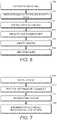
- FIG. 7sets forth one embodiment of steps that can be taken at the MRI clinic after the patient has undergone an MRI procedure.
- the programmer 140is used to perform a device check on the IMD during step 610.
- a device checkinvolves two stages. In a first stage, the programmer is gathering data from the IMD and possibly running a series of tests on the IMD. In the second stage of the device check, the programmer is analyzing the data gathered and test results to determine if the IMD is operating as expected and to identify any concerns about the patient. If the device check results are normal or as expected, then the IMD can be programmed with post-MRI settings at step 612. The post-MRI settings may be identical to or different from pre-MRI settings. In some embodiments, a first set of post-MRI settings are implemented, and then after time passes or a further device check is carried out, a second set of post-MRI settings are implemented.
- information from the device check and the settings restoration stepis provided to the patient's electronic medical record at step 614.
- the informationincludes a summary of programming changes that were made to IMD settings in one embodiment and device check data.
- information from the post-MRI device check and the settings restorationis sent to one or more health care professionals for review at step 616.
- a device checkis also carried out after the post-MRI settings are programmed.
- this informationis displayed to the MRI professional via the programmer 140.
- the post-MRI settingsare not programmed in this situation.
- the hardware and software described hereincan also be applied outside of the MRI context.
- the system and method steps described hereincan be used to execute a device prescription in order to change device parameters for a patient. These methods and systems are used where the health care professional with the expertise in making device programming changes is not in the same location as the patient at the time when the programming changes will to be implemented.
- the device prescriptioncan be stored on an external storage location as described herein, and then retrieved from the storage location by a programming device at a later time.
- the device that retrieves the device prescription from the storage locationcan be referred to as a retrieval programmer.
- the alternatives and details described above for an MRI prescription and MRI clinic programmeralso apply to a device prescription and a retrieval programmer used outside of the MRI context.
- Device prescriptionscan be useful in perioperative situations, as one example. Often, IMDs are turned off before surgery and then turned on after surgery. A device prescription to execute a device turn-off can be created and stored on a storage media. In one embodiment, the storage media is network connected to the apparatus that is used to create the device prescription. A device prescription form can be used to help the health care professional generate the device prescription. The use of a device prescription form can provide a simplified interface that is tailored for the perioperative situation.
- the apparatus used to create the device prescriptioncan be a smart phone, a desktop computer, a laptop computer, a tablet computer or another device.
- a retrieval programmercan be used to retrieve the device prescription from the storage media.
- the storage mediais network-connected and the retrieval programmer is also network connected.
- the retrieval programmerallows the user to select a simplified user interface that is tailored to the perioperative situation, and simplifies the process of programming the device before surgery.
- the retrieval programmercan also provide, in some embodiments, checklists for pre- and post-surgery actions and device checks.
- one or more health care professionalsare available to do one or more of assist the patient, retrieve identity data from the IMD, collect demographic data from the patient, check for a device prescription, program the device settings, conduct a medical procedure, program the IMD with post-procedure settings, and send a procedure report and device report to the patient's electronic medical record and other health care professionals.
- a device prescriptioncan be applied in many other contexts outside of the perioperative context.
- a device prescriptionprovided a secure digital format for device-specialist health care professionals to deliver device-related physician orders to a uniquely identified patient.
- the retrieval programmeris the device that initiates contact with a storage location, such as a server, to retrieve a device prescription with includes IMD programming instructions that have been stored there.
- the programmers 116 and 140can be for example, a programmer, a programmer/recorder/monitor device, a computer, a patient management system, a personal digital assistant (PDA), or the like.
- the term programmerrefers to a device that programs implanted devices and records data from implanted devices. A programmer may also allow monitoring of the implanted device.
- Exemplary programmer/recorder/monitor devicesinclude the Model 3120 Programmer, available from Boston Scientific Corporation, Natick, MA. The description of a programmer and its components can be applicable to a programmer 116 used in an device clinic or hospital, or a programmer 140 used in an MRI clinic, in various embodiments.
- the programmercan include a user input device, such as a keyboard and/or a mouse.
- the programmercan include a video output channel and video output device, such as a video display for displaying video output.
- the displayed video outputcan include a user interface screen.
- the video displaycan also be equipped with a touch screen, allowing it to serve as a user input device as well.
- the programmeralso sometimes referred to as an external interface device, can display real-time data and/or stored data graphically, such as in charts or graphs, and textually through the user interface screen.
- the programmercan present textual information to a user along with several response options.
- the programmercan also input and store a user's response to a question, and can store a user's text response in some embodiments.
- the external interface device or programmerwhich can also be referred to as a user interface, is in communication with a prescription server 132.
- the programmermay be in communication with multiple servers having different purposes.
- the communication link between the programmer and the servers 132 and 133may be via phone lines, the Internet 130, or any other data connection.
- the programmercan also be used when it is not in communication with an IMD device, but is only in communication with any of the servers.
- the programmeris capable of changing the operational parameters of the implantable medical device 110.
- programmersare used to interface with CRM devices in a clinic or hospital setting.
- the user of the programmeris a physician or trained technician.
- Programmerscan include components common to many computing devices, such as user interface devices to display and receive information from users.
- FIG. 8a diagram of various components of one embodiment of a programmer is shown in accordance with some embodiments of the invention. However, it is not required that an external interface device or programmer have all of the components illustrated in FIG. 8 .
- the programmerincludes a central processing unit (CPU) 805 or processor, which may include a conventional microprocessor, random access memory (RAM) 810 for temporary storage of information, and read only memory (ROM) 815 for permanent storage of information.
- CPUcentral processing unit
- RAMrandom access memory
- ROMread only memory
- a memory controller 820is provided for controlling system RAM 810.
- a bus controller 825is provided for controlling data bus 830, and an interrupt controller 835 is used for receiving and processing various interrupt signals from the other system components.
- Mass storagecan be provided by diskette drive 841, which is connected to bus 830 by controller 840, CD-ROM drive 846, which is connected to bus 830 by controller 845, and hard disk drive 851, which is connected to bus 830 by controller 850.
- User input to the programmer systemmay be provided by a number of devices.
- input devices 854such as a keyboard and mouse can connect to bus 830 by input device controller 855.
- DMA controller 860is provided for performing direct memory access to system RAM 810.
- a visual displayis generated by a video controller 865 or video output, which controls video display 870.
- the external systemcan also include a telemetry interface 890 or telemetry circuit which allows the external system to interface and exchange data with an implantable medical device. It will be appreciated that some embodiments may lack various elements illustrated in FIG. 8 .
- a seeding module, parameter interaction module, pace timing optimization module and combinations thereofcan be present in the programmer in different embodiments.
- the systemcan include an implantable medical device 110 disposed within a patient 112.
- the implantable medical device 110can be in communication with a programmer 116 and 140.
- communication between the implantable medical device 110 and the programmercan be via inductive communication through a wand 120 held on the outside of the patient 112 near the implantable medical device 110.
- communicationcan be carried out via radio frequency transmission, acoustically, or the like.
- the implantable medical device 110can include one or more implantable sensors in order to gather data regarding the patient 112.
- the implantable medical device 110can include an activity level sensor, a respiration sensor, a blood pressure sensor, an impedance sensor, or other sensors.
- the implantable medical device 110can be configured to store data over a period of time, and periodically communicate with the programmer 116 or programmer 140 or another device in order to transmit some or all of the stored data.
- the IMD 110is a CRM device and is coupled by one or more leads 122 to the heart 126.
- Cardiac leads 122include a proximal end that is coupled to IMD 110 and a distal end, coupled by an electrode or electrodes to one or more portions of a heart 126.
- the electrodestypically deliver cardioversion, defibrillation, pacing, or resynchronization therapy, or combinations thereof to at least one chamber of the heart 126.
- the electrodesmay be electrically coupled to sense amplifiers to sense electrical cardiac signals.
- the implantable medical system 900can include an implantable medical device 972 coupled to one or more stimulation leads 930 and 928.
- the implantable device 972can also include one or more physiological sensors 962, or other sensors, such as a pressure sensor, impedance sensor and others.
- the implantable devicecan include a microprocessor 948 (or processor) that communicates with a memory 946 via a bidirectional data bus.
- the memory 946typically comprises ROM or RAM for program storage and RAM for data storage.
- the implantable devicecan be configured to execute various operations such as processing of signals and execution of methods as described herein.
- a telemetry interface 964is also provided for communicating with an external unit, such as a programmer device or a patient management system.
- the implantable devicecan include ventricular sensing and pacing channels comprising sensing amplifier 952, output circuit 954, and a ventricular channel interface 950 which communicates bi-directionally with a port of microprocessor 948.
- the ventricular sensing and pacing channelcan be in communication with stimulation lead 930 and electrode 934.
- the implantable devicecan include atrial sensing and pacing channels comprising sensing amplifier 958, output circuit 960, and an atrial channel interface 956 which communicates bi-directionally with a port of microprocessor 948.
- the atrial sensing and pacing channelcan be in communication with stimulation lead 928 and electrode 932. For each channel, the same lead and electrode can be used for both sensing and pacing.
- the channel interfaces 950 and 956can include analog-to-digital converters for digitizing sensing signal inputs from the sensing amplifiers and registers which can be written to by the microprocessor in order to output pacing pulses, change the pacing pulse amplitude, and adjust the gain and threshold values for the sensing amplifiers.
- a seeding module, parameter interaction module, pace timing optimization module and combinations thereofcan be present in the device in different embodiments.
- the phrase “configured”describes a system, apparatus, or other structure that is constructed or configured to perform a particular task or adopt a particular configuration.
- the phrase “configured”can be used interchangeably with other similar phrases such as “arranged”, “arranged and configured”, “constructed and arranged”, “constructed”, “manufactured and arranged”, and the like.
- modules, circuitry, and methods shown and described herein with regard to various embodiments of the inventioncan be implemented using software, hardware, and combinations of software and hardware.
- the illustrated and/or described modules and circuitryare intended to encompass software implementations, hardware implementations, and software and hardware implementations.
Landscapes
- Health & Medical Sciences (AREA)
- Public Health (AREA)
- Engineering & Computer Science (AREA)
- Nuclear Medicine, Radiotherapy & Molecular Imaging (AREA)
- Radiology & Medical Imaging (AREA)
- Life Sciences & Earth Sciences (AREA)
- Animal Behavior & Ethology (AREA)
- Biomedical Technology (AREA)
- Veterinary Medicine (AREA)
- General Health & Medical Sciences (AREA)
- Heart & Thoracic Surgery (AREA)
- Physics & Mathematics (AREA)
- Electromagnetism (AREA)
- Cardiology (AREA)
- Magnetic Resonance Imaging Apparatus (AREA)
- Neurology (AREA)
Description
- The invention relates to implantable medical devices, such as cardiac rhythm management devices, and more particularly, to methods and systems for programming such devices in advance of a magnetic resonance imaging (MRI) procedure.
- Many different types of medical devices are implanted within patients to provide medical therapy. One type of an implanted medical device is a cardiac rhythm management device, such as a pacemaker or implantable defibrillator. Cardiac rhythm management (CRM) devices are used to provide medical therapy to patients who have a disorder related to cardiac rhythm, such as bradycardia or tachycardia.
- Magnetic resonance imaging (MRI) is a method of visualizing body tissues of a patient, primarily to identify pathological conditions or to visualize physiological structure for purposes of medical diagnosis and therapy. MRI relies on subjecting the body tissue of interest to a very strong uniform magnetic field, up to about 30,000 gauss, as well as a moderate strength but variable magnetic field of around 200 gauss. In the presence of these uniform and gradient magnetic fields, a radio frequency (RF) pulse is transmitted from a coil to the body tissue. Hydrogen atoms within the body tissue have a magnetic moment and tend to line up with the direction of the applied magnetic fields. Some of these hydrogen atoms will align facing one direction and others will align facing an opposite direction, such that most of the hydrogen atoms facing in alternating directions will tend to cancel each other out. However, a small percentage (but a significant absolute number) of hydrogen atoms will be unbalanced, or not cancelled out. The applied RF pulse tends to cause the unbalanced hydrogen protons to spin, or resonate, in a particular direction and at a particular frequency. When this RF pulse is turned off, the spinning hydrogen protons revert to their earlier, aligned position, and release their excess energy. The RF coil of the MRI machine is capable of detecting this emitted energy and transmitting a corresponding signal to a processor that transforms the signal to an image of the body tissue. Because different tissues have different characteristic responses to the application of the RF pulse in the presence of the magnetic fields, these differences can be utilized to prepare an image showing areas of contrasting tissue types.
- MRI techniques have proven to be very effective at diagnosing certain medical conditions and allowing for patients to receive timely, appropriate medical therapy.
- However, in many cases patients having an implanted medical device are contraindicated for MRI and MRI may be inappropriate for those patients.
- During imaging, the electromagnetic radiation produced by the MRI system may interfere with the operation of an IMD. In the case of cardiac devices, the presence of strong magnetic fields and RF energy during an MRI scan may prevent the charging of a high voltage capacitor within the cardiac device, which can affect the ability of the cardiac device to deliver electrical shocks to the patient when an event such as a tachyarrhythmia occurs.
- The RF energy and/or time varying gradient fields may prevent the sensing and detection of tachyarrhythmias by cardiac devices. The MRI system may also affect other types of implantable medical devices (IMDs).
- Some embodiments of IMDs provide for a method of operating an IMD in the presence of an MRI environment using particular MRI settings for the IMD. Examples of patents and patent publications that describe such methods and options for MRI settings for an IMD include
U.S. Published Patent Application No. 2010-0087892A1, Stubbs et al. ;U.S. Published Patent Application No. 2010-0106215A1, Stubbs et al ;U.S. Published Patent Application No. 2010-0211123A1, Stubbs et al ;U.S. Published Patent Application No. 2008-0221638A1, Wedan et al ;U.S. Patent No. 7,853,318, Wedan andU.S. Patent No. 7,873,412, Wedan . US 2010/0137945 A1 discloses a technique including transmitting information regarding MRI compatibility of an implanted medical device.- The present invention relates to a system as set out in
claim 1 and a method as set out in claim 13. Other embodiments are described in the dependent claims. - The invention may be more completely understood by considering the detailed description of various embodiments of the invention that follows in connection with the accompanying drawings.
FIG. 1 is a schematic view of one embodiment of a system for remote programming of an IMD with MRI settings.FIG. 2 is a flowchart showing a method for permitting or not permitting an MRI procedure for a patient having an IMD and for storing MRI settings.FIGS. 3 and 4 are perspective views of one embodiment of a programmer for use with the system ofFIG. 1 .FIG. 5 is a perspective view of one example of a communication module of the programmer ofFIGS. 3 and 4 , for inductive communication with and IMD.FIG. 6 is a flowchart showing a method for retrieving and programming MRI settings for a patient having an IMD.FIG. 7 is a flowchart showing a method for programming post-MRI settings to an IMD.FIG. 8 is a schematic diagram of an implementation of the components of an external interface device such as a programmer, in accordance with various embodiments.FIG. 9 is a block diagram of an implantable medical device.FIG. 10 is one embodiment of an MRI prescription form.- While the invention may be modified in many ways, specifics have been shown by way of example in the drawings and will be described in detail. It should be understood, however, that the intention is not to limit the invention to the particular embodiments described. On the contrary, the intention is to cover all modifications, equivalents, and alternatives following within the scope of the invention as defined by the claims.
- The invention relates to implantable medical devices such as cardiac rhythm management devices, and more particularly, to methods and systems for efficiently programming such devices. Still more particularly, embodiments of the invention relate to efficiently programming cardiac rhythm management devices in advance of a magnetic resonance imaging (MRI) procedure.
- Only certain medical professionals have received training in making programming changes to IMDs. That training involves familiarity with the particular model of IMD and its purpose, functions and setting options, knowledge of the relevant patient information that needs to be gathered and checked before programming, and familiarity with programming hardware used to accomplish the programming. These highly-trained individuals are in great demand, and are not present in every medical facility. If IMD settings need to be modified quickly or before a procedure, it can be challenging to locate such a highly-training professional to be present at the specific location along with the necessary programming hardware.
- One example of a procedure that often requires changes to the settings of an IMD is magnetic resonance imaging (MRI). To address this concern, many IMDs are capable of MRI settings that reduce the risks associated with an MRI. Another concern is that patients with IMDs need to be evaluated by a knowledgeable health care professional before permitting an MRI procedure.
- In one embodiment, a health care professional who is trained in IMD programming and in evaluating patients provides MRI settings for a particular IMD after evaluating the patient having the IMD. The MRI settings are provided to an external storage media where the MRI settings are stored. The MRI settings are stored on the external storage media in advance of the scheduled time for the MRI procedure.
- The external storage media can be a network server that is connected to the programmer used by the health care professional by the Internet or by another network. The external storage media can also be a portable storage device, such as a magnetic card or jump drive.
- Other information can be provided along with the MRI settings and can include identity data uniquely identifying the IMD or the patient. This group of information including the MRI settings can be referred to as an MRI prescription. The MRI prescription can also include computer readable instructions to carry out the programming of the MRI settings on the IMD. In some embodiments, the MRI prescription also includes identity data to identify the health care professional who evaluated the patient and provided the MRI settings. In one embodiment, the MRI prescription also includes a timer value indicating a length of time during which the MRI settings will be active. After the expiration of the timer value, the IMD will go out of the MRI mode and the parameter settings will revert back to the pre-MRI settings, in one embodiment. The MRI prescription also includes, in some embodiments, one or more of an indication of which chambers are paced, an MRI pacing mode, an MRI pace amplitude, an MRI pace rate, and an MRI pulse width. However, the concepts described herein are not limited to these particular settings or to cardiac devices. In other embodiments, different parameter values are provided for a cardiac device. In other embodiments, parameter values are provided for other IMDs.
- At the time of creating the MRI prescription, the health care professional also enters a timeframe over which the MRI prescription will be valid, in one embodiment. After the timeframe has passed, the MRI prescription cannot be retrieved from the storage media. The patient will be reevaluated and a new MRI prescription will be created.
- When the patient having the particular IMD arrives at the MRI clinic, an MRI technician uses a programmer device to access identity data on the IMD which uniquely identifies the particular IMD or particular patient. The MRI technician further uses the programmer to communicate with the external storage media to retrieve the previously-stored MRI prescription, including MRI settings, and program the IMD using the MRI settings. The existence of a previously-stored valid MRI prescription indicates that the patient has been evaluated and cleared for an MRI procedure.
- The programmer used by the MRI technician is able to communicate with the external storage media to retrieve the MRI settings that are associated with the IMD. A first communication module within the programmer carries out the communication with the external storage media. The programmer is also able to communicate with the IMD to determine the identity of the IMD or the patient and program the IMD with the MRI settings. The communication with the IMD is carried out by a device communication module of the programmer. The device communication module may communicate inductively, by radio frequency or other methods. The first communication module can communicate with the external storage media over a pervasive wireless network, over a wired network, or by other means. The programmer further includes a power source configured to supply power for components of the programmer. In one embodiment of such a system, the programmer has a portable housing configuration and the power supply is included in the housing.
FIG. 1 is a schematic view of one embodiment of a system for remote programming of an IMD with MRI settings. In this system, anIMD 110 is shown implanted in apatient 112. Thepatient 112 is shown present in a device clinic 114 and, at a later time, will also be present in anMRI clinic 115. Examples ofIMDs 110 include, without limitation, a cardiac device, a pacemaker, a defibrillator, a cardiac resynchronization therapy (CRT) device, an insulin pump, a loop recorder, a neurostimulator, a physiological sensor, a glucose meter or a combination of such devices. The system also includes andevice clinic programmer 116 or other external device that communicates wireless signals with theIMD 110, such as by using radio frequency (RF) or other telemetry signals. Alternatively, thedevice clinic programmer 116 communicates inductively using awand 120. Thedevice clinic programmer 116 can also communicate with an external storage media. The communication with the external storage media allows storage of MRI settings that are entered using thedevice clinic programmer 116. In the embodiment ofFIG. 1 , the external storage media is a part of aserver 132. It is also possible for the external storage media to be a portable storage device, such as a flash drive or magnetic card. Although the terms "server" and "prescription server" will be used to describe the storage location of the MRI settings in a number of embodiments described herein, including the embodiments ofFIG. 1 , it will be understood that it is also possible for the MRI settings to be stored on an external storage media different than a server.- There are many options for the hardware of the
device clinic programmer 116 and some of these options will be further described herein. In addition to thewand 120, thedevice clinic programmer 116 includes agraphical display 118 and user input devices such as in some embodiments a keyboard and a mouse. In the device clinic setting, a health care professional 128 can use the device clinic programmer to program IMDs, record data from IMDs, allow monitoring of the implanted device and upload information to aserver 132. The health care professional 128 can evaluate thepatient 112, the type ofIMD 110 and other factors and can determine the patient eligibility for an MRI procedure. - Although one configuration for a device clinic programmer is shown in
FIG. 1 , many other configurations are possible. For example, the device clinic programmer may have the shape of a laptop computer, a desktop computer, a tablet computer, a smart phone or another configuration. InFIG. 1 , thedevice clinic programmer 116 is depicted in a ruggedized laptop computer configuration. Thedevice clinic programmer 116 can also be referred to as a user interface or an external interface device. Thedevice clinic programmer 116 is in communication with a server, which can be referred to as aprescription server 132. The communication link between theprogrammer 116 and theserver 132 may be via phone lines, a wired network, theInternet 130, or any other data connection, such as a pervasive wireless network. Thedevice clinic programmer 116 can also be used when it is not in communication with an IMD device, but is only in communication with theserver 132. Thedevice clinic programmer 116 can also be used when it is not in communication with theserver 132, but is only in communication with an IMD. FIG. 2 sets forth one embodiment of steps for how a patient with an IMD may be evaluated for a possible MRI procedure. Instep 210, the patient undergoes an IMD implantation procedure. Later, possibly years later, the patient is identified as a candidate for an MRI procedure instep 212. In the process of preparing for the MRI, the patient may be rejected for the MRI due to the presence of the IMD instep 214. This step causes the patient to be directed to a health care professional having training related to the IMD for review of IMD details, patient condition and safety concerns related to the MRI procedure atstep 216. Now referring toFIG. 1 , this review by a health care professional 128 can take place in a device clinic 114 using thedevice clinic programmer 116 and a connection to theprescription server 132.- Again referring to
FIG. 2 , the health care professional determines whether an MRI procedure would be safe for the patient atstep 218. If no, the MRI is not permitted atstep 220. If yes, the health care professional generates an MRI prescription including MRI settings and causes those to be stored on theserver 132. At this point in time in the process, the MRI settings have not yet been programmed into the IMD. Instead, the MRI settings have been stored on theserver 132 for later retrieval at the time of the MRI procedure. - Particular steps that are taken by the device clinic programmer in some embodiments include interrogating the IMD to determine its status and download diagnostic and therapeutic information and displaying to the health care professional an MRI checklist. The MRI checklist is formulated to assist the professional with the assessment of whether or not an MRI should be permitted for the patient. If the health care professional determines that an MRI should be permitted, the device clinic programmer presents an MRI prescription form to the professional.
- One example of an
MRI prescription form 1000 is shown inFIG. 10 . TheMRI prescription form 1000 shown inFIG. 10 is formatted for display on a smart phone-type display. The professional uses the MRI prescription form to enter parameter data for the MRI settings. Some of the data entered are numerical values for particular parameter settings, such as the MRI timer and MRI pulse width. The MRI prescription form also includes, in some embodiments, one or more of an indication of which chambers are paced, an MRI pacing mode, an MRI pace amplitude, an MRI pace rate, an MRI settings timer and a selection for a validity timeframe. Some of the selections can be made on the portion of the form shown inFIG. 10 , while some selections are made by navigating to a different screen or portion of the form for further data entry. After entry of the data into the MRI prescription form, the programmer performs a range checking step in some embodiments. The range checking step compares the entered values against expectations regarding these values, to determine if the values are correct for the particular situation. In one example, the programmer checks to see that the timer value is a positive number and that it falls in a range of 1 to 24 hours. Other numerical values for the MRI settings are also compared to an expected range in some embodiments. - After the checking step is performed, then the device clinic programmer compiles the completed MRI prescription form into a structured text-based software program that can be executed at the MRI clinic to change the IMD settings.
- On the
server 132, the MRI prescription information is stored until retrieved. The MRI prescription is uniquely tagged with identify data, such as an identification number, that uniquely identifies the patient, the particular IMD or both. In one embodiment, the unique identity data stored on the IMD is a device serial number. - In some embodiments, a
second server 133 or additional servers are in communication with thedevice clinic programmer 116 and with theMRI clinic programmer 140. Thesecond server 133 can be a care server that allows clinicians to log in and view the details of what is happening with their patient's IMD performance or history. One example of such a system is the LATITUDE® Patient Management System that is designed for use with certain compatible pulse generators manufactured by Boston Scientific Corporation. It is also possible for the system to be connected to other servers, such as servers that store electronic medical records (EMRs) of patients. It is also possible for the programmer to communicate with a single server for multiple purposes, such as for retrieving prescriptions and for patient care, for patient care and EMRs, or for EMRs and retrieving prescriptions. - Again referring to
FIG. 1 , thepatient 112 having theIMD 110 is also depicted in anMRI clinic 115. Thepatient 112 would be at the MRI clinic only after the health care professional had stored the MRI settings on theserver 132. At theMRI clinic 115, anMRI device 134 is available for use and an MRI professional 136 is available to do one or more of assist the patient, retrieve identity data from theIMD 110, collect demographic data from the patient, check for an MRI prescription, program MRI settings, conduct the MRI procedure, program the IMD with post-MRI settings, and send an MRI report and device report to the patient's electronic medical record and other health care professionals. The MRI professional 128 uses anMRI clinic programmer 140 to communicate with theIMD 110 and to communicate with theserver 132. - In one embodiment, the
MRI clinic programmer 140 has a similar appearance and structure as thedevice clinic programmer 116. In another embodiment, depicted inFIG. 1 , and also shown inFIGS. 3-5 , theMRI clinic programmer 140 has a different appearance and structure compared to thedevice clinic programmer 116. In this embodiment, because theMRI professional 136 is likely to be an individual without significant training with IMD programming, theMRI clinic programmer 140 is provided with a simplified user interface and simplified functions compared to thedevice clinic programmer 116. It also possible for the simplified user interface depicted for theMRI clinic programmer 140 to be used as the device clinic programmer. Professionals with special training for IMDs can also benefit from a simplified user interface, especially when performing certain tasks. - Now referring to
FIGS. 1 and3-5 , in one embodiment, theMRI clinic programmer 140 includes ahousing 142 that is configured for portability by a user. For example, in one embodiment, the weight of theprogrammer 140 is less than three pounds. In another embodiment, theprogrammer 140 weighs less than two pounds. In one embodiment, a power source of theMRI clinic programmer 140 is contained within thehousing 142. The programmer includes atouch screen 146 in one embodiment, which allows for both a graphical display and user input. - The
programmer 140 includes a first communication module in thehousing 142 configured to communicate with theprescription server 132 in order to retrieve the MRI prescription including the MRI settings that are associated with the IMD. A first communication link between theprogrammer 140 and theprescription server 132 may be via a pervasive wireless network, conventional phone lines, theInternet 130, or any other data connection. Theprogrammer 140 can be used when it is not in communication with an IMD device, but is only in communication with theprescription server 132. - Generally, a pervasive wireless communication network is a communications network that can be used to directly communicate with a host computer without the need for a repeater device. A pervasive network includes those networks that are sufficiently prevalent or dispersed that an average person in the U.S. would be within range of interfacing with the network at some point during a normal daily routine. A pervasive wireless network typically has a relatively broad effective geographic span. There are many different usable pervasive wireless communication networks. One example is a wireless telephone network, such as a cellular telephone network. Other example embodiments of a pervasive wireless communication network include a wireless pager network, wireless wide area networks (WAN) such as those installed in certain public places like coffee shops, airports, schools, or municipalities, and wireless local area networks (LAN) including those following the standards set forth by the Institute for Electrical and Electronic Engineers (IEEE) in Standards 802.11(b) and (g).
- The
programmer 140 further includes adevice communication module 144 for communicating with theIMD 110 over a device communication link. Now referring toFIG. 5 , in one embodiment, thedevice communication module 144 includes atelemetry wand 146 on one end, aninterface module 148 on the other end, and aflexible cord 150 connecting them. Thetelemetry wand 146 can be positioned over the IMD to enable inductive communication with the IMD. In an alternative embodiment, the device communication module uses radio frequency (RF) or other telemetry signals to communicate with the IMD. - Now referring to
FIGS. 4 and5 , in one embodiment, theinterface module 148 is configured to be easily attached to and detached from the rest of theprogrammer 140.FIG. 5 shows the device communications module completely detached from the rest of theprogrammer 140.FIG. 4 illustrates thedevice communications module 144 attached to the rest of theprogrammer 140. Again referring toFIG. 5 , theinterface module 148 includes aninterface connector structure 152 which reversibly connects to a mating connector structure (not shown) on theprogrammer 140. The connector structure is removable from and replacable with the mating connector structure. Theinterface connector structure 152 is capable of carrying digital, bi-directional communication between thedevice communication module 144 and the rest of theprogrammer 140. Theinterface connector structure 152 is also capable of providing power to thedevice communication module 144 from theprogrammer 140. In one embodiment, a universal serial bus (USB) data transfer protocol is used. Other data transfer protocols and connector configurations could be used instead, such as an Ethernet connector, an IEE1394 interface (also known by the trade names of FireWire sold by Apple and iLink sold by Sony) and a Thunderbolt interface. Theinterface connector structure 152 is a USB connector with additional power connections in one embodiment. - Now referring to
FIG. 4 , in order to connect theinterface module 148 to the programmer, theinterface module 148 slides into arecess 154 on the side of theprogrammer 140. When theinterface module 148 is fully engaged in therecess 154, theconnector 152 engages the mating connector of the programmer. In one embodiment, then theinterface module 148 is fully engaged in the recess, the exterior of theinterface module 148 is flush with an exterior surface of theprogrammer 140. - It is possible that the
programmer 140 could be used with adevice communication module 144 provided by a manufacturer different from the manufacturer of the programmer, but still be configured to attach to theprogrammer 140. Such an arrangement would allow the MRI professional 136 to use asingle programmer 140 and user interface to make programming changes to IMDs from different manufacturers, thereby simplifying the equipment required at theMRI clinic 115. - In one embodiment shown in
FIG. 4 , thetelemetry wand 146 is configured to mechanically fit into and be held by a cradle structure on a back side of theprogrammer 140, for the convenience of the user of the programmer. FIG. 6 sets forth one embodiment of steps that can be taken at the MRI clinic to enable the patient to undergo an MRI procedure. The patient reports to the MRI clinic atstep 510. The MRI professional 136 uses theMRI clinic programmer 140, selecting the MRI Mode on the screen of theprogrammer 140 in one embodiment. Theprogrammer 140 communicates with theIMD 110 inductively, using thedevice communication module 144, and retrieves the identity data from theIMD 110 atstep 512. In some embodiments, thetelemetry module 146 is positioned over theIMD 110 duringstep 512 to facilitate inductive communication. Theprogrammer 140 then communicates with theserver 132 to retrieve an MRI prescription including MRI settings atstep 514. The existence of an MRI prescription indicates that an MRI is permissible.- In some embodiments, the health care professional collects demographic data from the patient and enters that data into the
programmer 140. Examples of demographic data that are collected in this embodiment include one or more of name, date of birth, social security number, health care system number, insurer number and other identifiers. The patient demographic data can be used to verify the patient identify. - In some embodiments, the retrieval of the identity data from the device automatically causes the
programmer 140 to contact the server and to automatically retrieve any valid MRI prescription that is saved on the server. In some embodiments, both the collected patient demographic data and the IMD identity data are sent to the server in order to retrieve the MRI prescription. - In some embodiments, the
programmer 140 performs range checking after the MRI prescription is retrieved and before the MRI settings are programmed. The range checking step compares the retrieved values for the numerical MRI settings values against expectations regarding these values. This step can help to identify if any problems during transmission of the MRI prescription have affected the MRI settings. - In some embodiments, additional steps such as encryption, digital signature, verification, confirmation and correctness checking are performed by the
programmer 116,programmer 140,server 132 or a combination of these devices to ensure that the correct settings are programmed and that there is no problem with the transmission of the MRI prescription. Examples of how these steps can be performed are described inU.S. Patent Application No. 2007/0185547 . - At
step 516, theprogrammer 140 communicates with the IMD to program the MRI settings. Atstep 518, theprogrammer 140 provides the MRI professional 136 with a list of safety checks to be performed. Once those safety checks are complete, the MRI is performed atstep 520. FIG. 7 sets forth one embodiment of steps that can be taken at the MRI clinic after the patient has undergone an MRI procedure. First, theprogrammer 140 is used to perform a device check on the IMD duringstep 610. In one embodiment, a device check involves two stages. In a first stage, the programmer is gathering data from the IMD and possibly running a series of tests on the IMD. In the second stage of the device check, the programmer is analyzing the data gathered and test results to determine if the IMD is operating as expected and to identify any concerns about the patient. If the device check results are normal or as expected, then the IMD can be programmed with post-MRI settings atstep 612. The post-MRI settings may be identical to or different from pre-MRI settings. In some embodiments, a first set of post-MRI settings are implemented, and then after time passes or a further device check is carried out, a second set of post-MRI settings are implemented.- After the post-MRI settings are programmed, information from the device check and the settings restoration step is provided to the patient's electronic medical record at
step 614. The information includes a summary of programming changes that were made to IMD settings in one embodiment and device check data. In addition, information from the post-MRI device check and the settings restoration is sent to one or more health care professionals for review atstep 616. In one embodiment, a device check is also carried out after the post-MRI settings are programmed. - If concerns are identified during the device check performed after the MRI, or if the device check fails to complete, this information is displayed to the MRI professional via the
programmer 140. In one embodiment, the post-MRI settings are not programmed in this situation. - The hardware and software described herein can also be applied outside of the MRI context. Instead of an MRI prescription, the system and method steps described herein can be used to execute a device prescription in order to change device parameters for a patient. These methods and systems are used where the health care professional with the expertise in making device programming changes is not in the same location as the patient at the time when the programming changes will to be implemented. The device prescription can be stored on an external storage location as described herein, and then retrieved from the storage location by a programming device at a later time. The device that retrieves the device prescription from the storage location can be referred to as a retrieval programmer. The alternatives and details described above for an MRI prescription and MRI clinic programmer also apply to a device prescription and a retrieval programmer used outside of the MRI context.
- Device prescriptions can be useful in perioperative situations, as one example. Often, IMDs are turned off before surgery and then turned on after surgery. A device prescription to execute a device turn-off can be created and stored on a storage media. In one embodiment, the storage media is network connected to the apparatus that is used to create the device prescription. A device prescription form can be used to help the health care professional generate the device prescription. The use of a device prescription form can provide a simplified interface that is tailored for the perioperative situation. The apparatus used to create the device prescription can be a smart phone, a desktop computer, a laptop computer, a tablet computer or another device.
- Just before surgery, another health care professional can use a retrieval programmer to retrieve the device prescription from the storage media. In one embodiment, the storage media is network-connected and the retrieval programmer is also network connected. In one embodiment, the retrieval programmer allows the user to select a simplified user interface that is tailored to the perioperative situation, and simplifies the process of programming the device before surgery. The retrieval programmer can also provide, in some embodiments, checklists for pre- and post-surgery actions and device checks.
- At the location where the device prescription will be implemented, one or more health care professionals are available to do one or more of assist the patient, retrieve identity data from the IMD, collect demographic data from the patient, check for a device prescription, program the device settings, conduct a medical procedure, program the IMD with post-procedure settings, and send a procedure report and device report to the patient's electronic medical record and other health care professionals.
- A device prescription can be applied in many other contexts outside of the perioperative context. A device prescription provided a secure digital format for device-specialist health care professionals to deliver device-related physician orders to a uniquely identified patient.
- One aspect of the device prescription systems and methods described herein is that the retrieval programmer is the device that initiates contact with a storage location, such as a server, to retrieve a device prescription with includes IMD programming instructions that have been stored there.
- The
programmers programmer 116 used in an device clinic or hospital, or aprogrammer 140 used in an MRI clinic, in various embodiments. - The programmer can include a user input device, such as a keyboard and/or a mouse. The programmer can include a video output channel and video output device, such as a video display for displaying video output. The displayed video output can include a user interface screen. In addition, the video display can also be equipped with a touch screen, allowing it to serve as a user input device as well.
- The programmer, also sometimes referred to as an external interface device, can display real-time data and/or stored data graphically, such as in charts or graphs, and textually through the user interface screen. In addition, the programmer can present textual information to a user along with several response options. The programmer can also input and store a user's response to a question, and can store a user's text response in some embodiments.
- In one embodiment, the external interface device or programmer, which can also be referred to as a user interface, is in communication with a
prescription server 132. The programmer may be in communication with multiple servers having different purposes. The communication link between the programmer and theservers Internet 130, or any other data connection. The programmer can also be used when it is not in communication with an IMD device, but is only in communication with any of the servers. - In one embodiment, the programmer is capable of changing the operational parameters of the implantable
medical device 110. Typically, programmers are used to interface with CRM devices in a clinic or hospital setting. In this context, the user of the programmer is a physician or trained technician. - Programmers can include components common to many computing devices, such as user interface devices to display and receive information from users. Referring now to
FIG. 8 , a diagram of various components of one embodiment of a programmer is shown in accordance with some embodiments of the invention. However, it is not required that an external interface device or programmer have all of the components illustrated inFIG. 8 . - In one embodiment, the programmer includes a central processing unit (CPU) 805 or processor, which may include a conventional microprocessor, random access memory (RAM) 810 for temporary storage of information, and read only memory (ROM) 815 for permanent storage of information. A
memory controller 820 is provided for controllingsystem RAM 810. Abus controller 825 is provided for controllingdata bus 830, and an interruptcontroller 835 is used for receiving and processing various interrupt signals from the other system components. - Mass storage can be provided by
diskette drive 841, which is connected tobus 830 bycontroller 840, CD-ROM drive 846, which is connected tobus 830 bycontroller 845, andhard disk drive 851, which is connected tobus 830 bycontroller 850. User input to the programmer system may be provided by a number of devices. For example,input devices 854 such as a keyboard and mouse can connect tobus 830 byinput device controller 855.DMA controller 860 is provided for performing direct memory access tosystem RAM 810. A visual display is generated by avideo controller 865 or video output, which controlsvideo display 870. The external system can also include atelemetry interface 890 or telemetry circuit which allows the external system to interface and exchange data with an implantable medical device. It will be appreciated that some embodiments may lack various elements illustrated inFIG. 8 . - A seeding module, parameter interaction module, pace timing optimization module and combinations thereof can be present in the programmer in different embodiments.
- For convenience, the description herein will occasionally make reference to cardiac devices and issues with treating tachyarrhythmia. However, the methods and systems described herein are broadly applicable to many different types of IMDs, including non-cardiac devices. The applications discussed herein are intended to be exemplary and not limiting.
- One embodiment of an IMD system will now be described in more detail with reference to
FIG. 1 , which is a schematic of an exemplary IMD system. The system can include an implantablemedical device 110 disposed within apatient 112. The implantablemedical device 110 can be in communication with aprogrammer medical device 110 and the programmer can be via inductive communication through awand 120 held on the outside of thepatient 112 near the implantablemedical device 110. However, in other embodiments, communication can be carried out via radio frequency transmission, acoustically, or the like. - The implantable
medical device 110 can include one or more implantable sensors in order to gather data regarding thepatient 112. For example, the implantablemedical device 110 can include an activity level sensor, a respiration sensor, a blood pressure sensor, an impedance sensor, or other sensors. - The implantable
medical device 110 can be configured to store data over a period of time, and periodically communicate with theprogrammer 116 orprogrammer 140 or another device in order to transmit some or all of the stored data. - In one embodiment, the
IMD 110 is a CRM device and is coupled by one or more leads 122 to theheart 126. Cardiac leads 122 include a proximal end that is coupled toIMD 110 and a distal end, coupled by an electrode or electrodes to one or more portions of aheart 126. The electrodes typically deliver cardioversion, defibrillation, pacing, or resynchronization therapy, or combinations thereof to at least one chamber of theheart 126. The electrodes may be electrically coupled to sense amplifiers to sense electrical cardiac signals. - Referring now to
FIG. 9 , some components of an exemplaryimplantable system 900 are schematically illustrated. The implantablemedical system 900 can include an implantablemedical device 972 coupled to one or more stimulation leads 930 and 928. Theimplantable device 972 can also include one or morephysiological sensors 962, or other sensors, such as a pressure sensor, impedance sensor and others. - The implantable device can include a microprocessor 948 (or processor) that communicates with a
memory 946 via a bidirectional data bus. Thememory 946 typically comprises ROM or RAM for program storage and RAM for data storage. The implantable device can be configured to execute various operations such as processing of signals and execution of methods as described herein. Atelemetry interface 964 is also provided for communicating with an external unit, such as a programmer device or a patient management system. - The implantable device can include ventricular sensing and pacing channels comprising
sensing amplifier 952,output circuit 954, and aventricular channel interface 950 which communicates bi-directionally with a port ofmicroprocessor 948. The ventricular sensing and pacing channel can be in communication withstimulation lead 930 andelectrode 934. The implantable device can include atrial sensing and pacing channels comprisingsensing amplifier 958,output circuit 960, and anatrial channel interface 956 which communicates bi-directionally with a port ofmicroprocessor 948. The atrial sensing and pacing channel can be in communication withstimulation lead 928 andelectrode 932. For each channel, the same lead and electrode can be used for both sensing and pacing. The channel interfaces 950 and 956 can include analog-to-digital converters for digitizing sensing signal inputs from the sensing amplifiers and registers which can be written to by the microprocessor in order to output pacing pulses, change the pacing pulse amplitude, and adjust the gain and threshold values for the sensing amplifiers. - A seeding module, parameter interaction module, pace timing optimization module and combinations thereof can be present in the device in different embodiments.
- It should be noted that, as used in this specification and the appended claims, the singular forms "a," "an," and "the" include plural referents unless the content clearly dictates otherwise. It should also be noted that the term "or" is generally employed in its sense including "and/or" unless the content clearly dictates otherwise.
- It should also be noted that, as used in this specification and the appended claims, the phrase "configured" describes a system, apparatus, or other structure that is constructed or configured to perform a particular task or adopt a particular configuration. The phrase "configured" can be used interchangeably with other similar phrases such as "arranged", "arranged and configured", "constructed and arranged", "constructed", "manufactured and arranged", and the like.
- One of ordinary skill in the art will understand that the modules, circuitry, and methods shown and described herein with regard to various embodiments of the invention can be implemented using software, hardware, and combinations of software and hardware. As such, the illustrated and/or described modules and circuitry are intended to encompass software implementations, hardware implementations, and software and hardware implementations.
Claims (15)
- A system comprising:an implantable medical device (IMD) (110) configured to be programmed with magnetic resonance imaging (MRI) settings for use during an MRI scan, wherein the IMD stores identity data that uniquely identifies the IMD (110) or a patient having the IMD;an external storage media (132) configured to receive MRI settings associated with the IMD (110) and configured to store the MRI settings associated with the IMD (110); anda programmer (140) configured to retrieve identity data (512) from the IMD (110), retrieve MRI settings (514) associated with the IMD (110) from the external storage media (132) and program the IMD (110) using the MRI settings (516),characterized in that the MRI settings (514) include one or more of numerical values for particular parameter settings, an indication of which chambers are paced, an MRI pacing mode, an MRI pace amplitude, an MRI pace rate, an MRI settings timer and a validity timeframe.
- The system of claim 1, wherein the programmer (140) comprises:a first communication module configured to communicate with the external storage media (132) to retrieve the MRI settings that are associated with the IMD (110); anda device communication module (144) configured to communicate with the IMD (110) to determine the identity of the IMD (110) or patient and program the IMD with the MRI settings (516).
- The system of claim 2, wherein the first communication module of the programmer isconfigured for communication with the external storage media over a pervasive wirelesscommunication network that can be used to directly communicate with a host computer.
- The system of claim 2, wherein the first communication module of the programmer (140) is configured for communication with the external storage media (132) over a wired network.
- The system of claim 2, wherein the device communication module (144) of the programmer (140) is configured for inductive communication with the IMD (110).
- The system of claim 2, wherein the device communication module (144) comprises a removable and replaceable connection to the programmer.
- The system of claim 2, wherein the device communication module (144) of the programmer is configured for radio frequency communication with the IMD.
- The system of claim 2, the programmer further comprising a housing (142) configured for portability by user, wherein power source is provided in the housing.
- The system of claim 1 wherein the programmer is further configured to program the IMD with post-MRI settings.
- The system of 1, wherein the programmer is further configured to perform a device check on the IMD (612).
- The system of claim 1, wherein the external storage media (132) is configured to store an MRI prescription, wherein the MRI prescription comprises MRI settings and the identity data.
- The system of claim 1, wherein the external storage media (132) is a part of a server.
- A method for conducting a magnetic resonance imaging (MRI) scan of a patient (112) having an implantable medical device (IMD) (110):storing MRI settings for an IMD (222) on an external storage media (132),wherein the IMD (110) stores identity data that uniquely identifies the IMD (110) or the patient (112); andidentifying the IMD (110) or patient (112) using a programmer (140) to communicate with the IMD (110); andusing the programmer (140) to retrieve the MRI settings from the external storage media (514),characterized in that the MRI settings (514) include one or more of numerical values for particular parameter settings, an indication of which chambers are paced, an MRI pacing mode, an MRI pace amplitude, an MRI pace rate, an MRI settings timer and a validity timeframe.
- The method of claim 13, further comprising the programmer (140) performing safety checks before an MRI scan (518).
- The method of claim 13, further comprising the programmer (140) sending information to an electronic medical record, a health care professional, or both wherein the information includes a summary of changes to IMD settings and device check data (614, 616).
Priority Applications (1)
| Application Number | Priority Date | Filing Date | Title |
|---|---|---|---|
| EP22167874.1AEP4049713A1 (en) | 2011-08-31 | 2012-08-23 | System and method for the remote programming of mri settings of an implantable medical device |
Applications Claiming Priority (3)
| Application Number | Priority Date | Filing Date | Title |
|---|---|---|---|
| US201161529592P | 2011-08-31 | 2011-08-31 | |
| US13/591,469US9272152B2 (en) | 2011-08-31 | 2012-08-22 | Remote programming of MRI settings of an implantable medical device |
| PCT/US2012/052099WO2013032864A1 (en) | 2011-08-31 | 2012-08-23 | System and method for the remote programming of mri settings of an implantable medical device |
Related Child Applications (1)
| Application Number | Title | Priority Date | Filing Date |
|---|---|---|---|
| EP22167874.1ADivisionEP4049713A1 (en) | 2011-08-31 | 2012-08-23 | System and method for the remote programming of mri settings of an implantable medical device |
Publications (2)
| Publication Number | Publication Date |
|---|---|
| EP2750757A1 EP2750757A1 (en) | 2014-07-09 |
| EP2750757B1true EP2750757B1 (en) | 2022-04-13 |
Family
ID=47744764
Family Applications (2)
| Application Number | Title | Priority Date | Filing Date |
|---|---|---|---|
| EP12759302.8AActiveEP2750757B1 (en) | 2011-08-31 | 2012-08-23 | System and method for the remote programming of mri settings of an implantable medical device |
| EP22167874.1APendingEP4049713A1 (en) | 2011-08-31 | 2012-08-23 | System and method for the remote programming of mri settings of an implantable medical device |
Family Applications After (1)
| Application Number | Title | Priority Date | Filing Date |
|---|---|---|---|
| EP22167874.1APendingEP4049713A1 (en) | 2011-08-31 | 2012-08-23 | System and method for the remote programming of mri settings of an implantable medical device |
Country Status (3)
| Country | Link |
|---|---|
| US (3) | US9272152B2 (en) |
| EP (2) | EP2750757B1 (en) |
| WO (1) | WO2013032864A1 (en) |
Families Citing this family (8)
| Publication number | Priority date | Publication date | Assignee | Title |
|---|---|---|---|---|
| US9174058B2 (en) | 2009-09-29 | 2015-11-03 | Medtronic, Inc. | Automatic selection of parameters of an exposure mode of an implantable medical device |
| US9272152B2 (en) | 2011-08-31 | 2016-03-01 | Cardiac Pacemakers, Inc. | Remote programming of MRI settings of an implantable medical device |
| US9452293B2 (en) | 2014-06-19 | 2016-09-27 | Inspire Medical Systems, Inc. | Hybrid communication channel for communicating with an implantable medical device |
| US10293167B2 (en) | 2016-04-15 | 2019-05-21 | Medtronic, Inc. | Methods and implantable medical systems that implement exposure modes of therapy that allow for continued operation during exposure to a magnetic disturbance |
| CN107247886A (en)* | 2017-07-18 | 2017-10-13 | 重庆锦垚生物科技有限公司 | A kind of remote rehabilitation system based on internet |
| WO2019152342A1 (en) | 2018-02-01 | 2019-08-08 | Cardiac Pacemakers, Inc. | An insertable cardiac monitoring device designed for the mri environment |
| JP2023524630A (en)* | 2020-05-06 | 2023-06-13 | バイオトロニック エスエー アンド カンパニー カーゲー | A medical system that performs therapeutic functions on a patient |
| US20240203550A1 (en)* | 2022-12-14 | 2024-06-20 | Pacesetter, Inc. | Platform supporting centralized access for remote mri workflow for implanted devices |
Family Cites Families (63)
| Publication number | Priority date | Publication date | Assignee | Title |
|---|---|---|---|---|
| EP0781428B1 (en) | 1994-09-13 | 1998-02-11 | Irmgard Rost | Data archive system |
| US5659741A (en) | 1995-03-29 | 1997-08-19 | Stuart S. Bowie | Computer system and method for storing medical histories using a carrying size card |
| US5724985A (en) | 1995-08-02 | 1998-03-10 | Pacesetter, Inc. | User interface for an implantable medical device using an integrated digitizer display screen |
| US6356789B1 (en) | 1997-11-07 | 2002-03-12 | Medtronic Inc. | Medical information device |
| US7181505B2 (en) | 1999-07-07 | 2007-02-20 | Medtronic, Inc. | System and method for remote programming of an implantable medical device |
| US6804558B2 (en) | 1999-07-07 | 2004-10-12 | Medtronic, Inc. | System and method of communicating between an implantable medical device and a remote computer system or health care provider |
| US6654642B2 (en) | 1999-09-29 | 2003-11-25 | Medtronic, Inc. | Patient interactive neurostimulation system and method |
| US7039810B1 (en) | 1999-11-02 | 2006-05-02 | Medtronic, Inc. | Method and apparatus to secure data transfer from medical device systems |
| US7060031B2 (en) | 1999-12-17 | 2006-06-13 | Medtronic, Inc. | Method and apparatus for remotely programming implantable medical devices |
| US6497655B1 (en) | 1999-12-17 | 2002-12-24 | Medtronic, Inc. | Virtual remote monitor, alert, diagnostics and programming for implantable medical device systems |
| US6880085B1 (en) | 2000-11-01 | 2005-04-12 | Cardiac Pacemakers, Inc. | Security system for implantable medical devices |
| US20030028883A1 (en) | 2001-07-30 | 2003-02-06 | Digeo, Inc. | System and method for using user-specific information to configure and enable functions in remote control, broadcast and interactive systems |
| US7092761B1 (en) | 2002-11-06 | 2006-08-15 | Pacesetter, Inc. | Telemetry wand with display and control for implantable medical devices |
| US7660620B2 (en) | 2003-09-29 | 2010-02-09 | Medtronic, Inc. | Timing techniques for magnetic resonance imaging |
| US7761167B2 (en) | 2004-06-10 | 2010-07-20 | Medtronic Urinary Solutions, Inc. | Systems and methods for clinician control of stimulation systems |
| US7565197B2 (en) | 2004-06-18 | 2009-07-21 | Medtronic, Inc. | Conditional requirements for remote medical device programming |
| EP1793728B1 (en) | 2004-07-27 | 2015-04-15 | The Cleveland Clinic Foundation | Integrated system for mri-safe implantable devices |
| US7418296B2 (en) | 2004-07-30 | 2008-08-26 | Cardiac Pacemakers, Inc. | Wireless pacing system analyzer in a programmer system |
| US8014867B2 (en) | 2004-12-17 | 2011-09-06 | Cardiac Pacemakers, Inc. | MRI operation modes for implantable medical devices |
| US7561915B1 (en) | 2004-12-17 | 2009-07-14 | Cardiac Pacemakers, Inc. | MRI system having implantable device safety features |
| US20060173718A1 (en) | 2005-02-02 | 2006-08-03 | Murphy Daniel J | Medical information card and system and method for using same |
| US20070136098A1 (en) | 2005-12-12 | 2007-06-14 | Smythe Alan H | System and method for providing a secure feature set distribution infrastructure for medical device management |
| WO2007081829A2 (en) | 2006-01-09 | 2007-07-19 | Cardiac Pacemakers, Inc. | Remotely programming a patient medical device |
| US7509167B2 (en) | 2006-02-16 | 2009-03-24 | Cardiac Pacemakers, Inc. | MRI detector for implantable medical device |
| US9549688B2 (en) | 2006-04-24 | 2017-01-24 | Medtronic, Inc. | Implantable medical device detection |
| US7840276B2 (en) | 2006-04-26 | 2010-11-23 | Medtronic, Inc. | Generic device programmer network interface |
| US8049489B2 (en) | 2006-07-26 | 2011-11-01 | Cardiac Pacemakers, Inc. | Systems and methods for sensing external magnetic fields in implantable medical devices |
| US20080082144A1 (en) | 2006-09-29 | 2008-04-03 | James Marcotte | Universal usb-based telemetry rf head |
| WO2008051939A2 (en)* | 2006-10-24 | 2008-05-02 | Medapps, Inc. | Systems and methods for medical data transmission |
| US8295938B2 (en) | 2006-12-06 | 2012-10-23 | Medtronic, Inc. | Programming a medical device with a general purpose instrument |
| US7873412B2 (en) | 2007-02-28 | 2011-01-18 | Cardiac Pacemakers, Inc. | Induced current measurement systems and methods |
| US9345888B2 (en) | 2007-03-09 | 2016-05-24 | Cardiac Pacemakers, Inc. | MRI compatible implantable medical devices and methods |
| US7853318B2 (en) | 2007-03-14 | 2010-12-14 | Cardiac Pacemakers, Inc. | Cardiac sensing by implantable medical devices during magnetic resonance imaging |
| US8347365B2 (en) | 2007-03-29 | 2013-01-01 | Cardiac Pacemakers, Inc. | System and method for confirming identity and authority by a patient medical device |
| US20090048644A1 (en) | 2007-08-14 | 2009-02-19 | Stahmann Jeffrey E | System and method for providing intrabody data security on an active implantable medical device |
| US9848058B2 (en) | 2007-08-31 | 2017-12-19 | Cardiac Pacemakers, Inc. | Medical data transport over wireless life critical network employing dynamic communication link mapping |
| US20090063193A1 (en) | 2007-08-31 | 2009-03-05 | Mike Barton | Dashboard diagnostics for wireless patient communicator |
| JP2011505964A (en) | 2007-12-12 | 2011-03-03 | カーディアック ペースメイカーズ, インコーポレイテッド | Implantable medical device with Hall sensor |
| US8509910B2 (en) | 2007-12-14 | 2013-08-13 | Cardiac Pacemakers, Inc. | Telemetry during safety mode operation |
| US8160717B2 (en) | 2008-02-19 | 2012-04-17 | Cardiac Pacemakers, Inc. | Model reference identification and cancellation of magnetically-induced voltages in a gradient magnetic field |
| US8090443B2 (en) | 2008-09-15 | 2012-01-03 | Xiaoyi Min | Monitoring HF exacerbation and cardiac resynchronization therapy performance |
| CN102164630A (en) | 2008-09-15 | 2011-08-24 | 心脏起搏器公司 | Systems and methods for highly safe adjustment of device parameters |
| US8571661B2 (en) | 2008-10-02 | 2013-10-29 | Cardiac Pacemakers, Inc. | Implantable medical device responsive to MRI induced capture threshold changes |
| US20100106215A1 (en) | 2008-10-23 | 2010-04-29 | Stubbs Scott R | Systems and methods to detect implantable medical device configuaration changes affecting mri conditional safety |
| US8299899B2 (en) | 2008-11-19 | 2012-10-30 | Greatbatch Ltd. | AIMD external programmer incorporating a multifunction RFID reader having a limited transmit time and a time-out period |
| US8712540B2 (en)* | 2008-11-26 | 2014-04-29 | Medtronic, Inc. | Patient programmer with automated MRI compatibility verification for active implantable medical device |
| US8150516B2 (en) | 2008-12-11 | 2012-04-03 | Pacesetter, Inc. | Systems and methods for operating an implantable device for medical procedures |
| EP2398553B1 (en) | 2009-02-19 | 2015-07-22 | Cardiac Pacemakers, Inc. | Systems for providing arrhythmia therapy in mri environments |
| US9174058B2 (en)* | 2009-09-29 | 2015-11-03 | Medtronic, Inc. | Automatic selection of parameters of an exposure mode of an implantable medical device |
| EP2315465A1 (en) | 2009-10-20 | 2011-04-27 | ETH Zurich | Method for secure communication between devices |
| JP5558583B2 (en) | 2009-12-08 | 2014-07-23 | カーディアック ペースメイカーズ, インコーポレイテッド | Implantable medical device including automatic tachycardia detection and control in an MRI environment |
| US8538550B2 (en) | 2009-12-29 | 2013-09-17 | Cardiac Pacemakers, Inc. | Implantable device failsafe mode for MRI |
| US8391992B2 (en) | 2009-12-30 | 2013-03-05 | Cardiac Pacemakers, Inc. | Implantable medical device switching power supply including multiple modes |
| US8750997B2 (en) | 2009-12-31 | 2014-06-10 | Cardiac Pacemakers, Inc. | Implantable medical device including isolation test circuit |
| US20110160567A1 (en) | 2009-12-31 | 2011-06-30 | Stahmann Jeffrey E | Functional mri cardiac optimization |
| US20110160565A1 (en) | 2009-12-31 | 2011-06-30 | Stubbs Scott R | Detecting proximity to mri scanner |
| US8755886B2 (en) | 2009-12-31 | 2014-06-17 | Cardiac Pacemakers, Inc. | Implantable device with bias for MRI |
| US8855784B2 (en) | 2009-12-31 | 2014-10-07 | Cardiac Pacemakers, Inc. | Implantable medical device including controllably isolated housing |
| US9008788B2 (en)* | 2010-02-10 | 2015-04-14 | Medtronic, Inc. | Enablement and/or disablement of an exposure mode of an implantable medical device |
| US20110196450A1 (en)* | 2010-02-10 | 2011-08-11 | Medtronic, Inc. | Electronic prescription activation device |
| US9272152B2 (en) | 2011-08-31 | 2016-03-01 | Cardiac Pacemakers, Inc. | Remote programming of MRI settings of an implantable medical device |
| US11027138B2 (en) | 2012-08-27 | 2021-06-08 | Cardiac Pacemakers, Inc. | Location-based services |
| US9031652B2 (en) | 2012-08-27 | 2015-05-12 | Cardiac Pacemakers, Inc. | Use case-based services |
- 2012
- 2012-08-22USUS13/591,469patent/US9272152B2/enactiveActive
- 2012-08-23EPEP12759302.8Apatent/EP2750757B1/enactiveActive
- 2012-08-23WOPCT/US2012/052099patent/WO2013032864A1/enunknown
- 2012-08-23EPEP22167874.1Apatent/EP4049713A1/enactivePending
- 2016
- 2016-01-29USUS15/010,511patent/US9586043B2/enactiveActive
- 2017
- 2017-01-31USUS15/421,309patent/US9827417B2/enactiveActive
Also Published As
| Publication number | Publication date |
|---|---|
| US20160144169A1 (en) | 2016-05-26 |
| US9827417B2 (en) | 2017-11-28 |
| US20130053920A1 (en) | 2013-02-28 |
| US9586043B2 (en) | 2017-03-07 |
| US20170136234A1 (en) | 2017-05-18 |
| EP4049713A1 (en) | 2022-08-31 |
| US9272152B2 (en) | 2016-03-01 |
| EP2750757A1 (en) | 2014-07-09 |
| WO2013032864A1 (en) | 2013-03-07 |
Similar Documents
| Publication | Publication Date | Title |
|---|---|---|
| US9827417B2 (en) | Remote programming of MRI settings of an implantable medical device | |
| US10251573B2 (en) | Electrogram summary | |
| US8298153B2 (en) | System and method for the detection of acute myocardial infarction | |
| US20100010832A1 (en) | System and Method for The Diagnosis and Alert of A Medical Condition Initiated By Patient Symptoms | |
| US20130218582A1 (en) | Telemedicine system for imd patients using audio/video data | |
| US20010031998A1 (en) | Information network interrogation of an implanted device | |
| US9265960B2 (en) | Use case-based services | |
| EP3179908B1 (en) | Implanted lead analysis system and method | |
| US8600506B2 (en) | Systems and methods for collecting patient event information | |
| Siddamsetti et al. | Remote programming of cardiac implantable electronic devices: A novel approach to program cardiac devices for magnetic resonance imaging | |
| WO2021236177A1 (en) | System for core-device monitoring | |
| US9440088B2 (en) | Implanted lead analysis system and method | |
| US7738960B2 (en) | System and method for remote pacing threshold assessment | |
| CN114078589B (en) | Medical follow-up device, method, medium and apparatus for medical follow-up | |
| WO2024089529A1 (en) | Medical device implantation by perioperative patient evaluation preparation |
Legal Events
| Date | Code | Title | Description |
|---|---|---|---|
| PUAI | Public reference made under article 153(3) epc to a published international application that has entered the european phase | Free format text:ORIGINAL CODE: 0009012 | |
| 17P | Request for examination filed | Effective date:20140325 | |
| AK | Designated contracting states | Kind code of ref document:A1 Designated state(s):AL AT BE BG CH CY CZ DE DK EE ES FI FR GB GR HR HU IE IS IT LI LT LU LV MC MK MT NL NO PL PT RO RS SE SI SK SM TR | |
| DAX | Request for extension of the european patent (deleted) | ||
| STAA | Information on the status of an ep patent application or granted ep patent | Free format text:STATUS: EXAMINATION IS IN PROGRESS | |
| 17Q | First examination report despatched | Effective date:20190613 | |
| GRAP | Despatch of communication of intention to grant a patent | Free format text:ORIGINAL CODE: EPIDOSNIGR1 | |
| STAA | Information on the status of an ep patent application or granted ep patent | Free format text:STATUS: GRANT OF PATENT IS INTENDED | |
| GRAJ | Information related to disapproval of communication of intention to grant by the applicant or resumption of examination proceedings by the epo deleted | Free format text:ORIGINAL CODE: EPIDOSDIGR1 | |
| GRAP | Despatch of communication of intention to grant a patent | Free format text:ORIGINAL CODE: EPIDOSNIGR1 | |
| INTG | Intention to grant announced | Effective date:20211013 | |
| INTG | Intention to grant announced | Effective date:20211026 | |
| GRAS | Grant fee paid | Free format text:ORIGINAL CODE: EPIDOSNIGR3 | |
| GRAA | (expected) grant | Free format text:ORIGINAL CODE: 0009210 | |
| STAA | Information on the status of an ep patent application or granted ep patent | Free format text:STATUS: THE PATENT HAS BEEN GRANTED | |
| AK | Designated contracting states | Kind code of ref document:B1 Designated state(s):AL AT BE BG CH CY CZ DE DK EE ES FI FR GB GR HR HU IE IS IT LI LT LU LV MC MK MT NL NO PL PT RO RS SE SI SK SM TR | |
| REG | Reference to a national code | Ref country code:GB Ref legal event code:FG4D | |
| REG | Reference to a national code | Ref country code:CH Ref legal event code:EP | |
| REG | Reference to a national code | Ref country code:DE Ref legal event code:R096 Ref document number:602012078035 Country of ref document:DE | |
| REG | Reference to a national code | Ref country code:IE Ref legal event code:FG4D | |
| REG | Reference to a national code | Ref country code:AT Ref legal event code:REF Ref document number:1482928 Country of ref document:AT Kind code of ref document:T Effective date:20220515 | |
| REG | Reference to a national code | Ref country code:LT Ref legal event code:MG9D | |
| REG | Reference to a national code | Ref country code:NL Ref legal event code:MP Effective date:20220413 | |
| REG | Reference to a national code | Ref country code:AT Ref legal event code:MK05 Ref document number:1482928 Country of ref document:AT Kind code of ref document:T Effective date:20220413 | |
| PG25 | Lapsed in a contracting state [announced via postgrant information from national office to epo] | Ref country code:NL Free format text:LAPSE BECAUSE OF FAILURE TO SUBMIT A TRANSLATION OF THE DESCRIPTION OR TO PAY THE FEE WITHIN THE PRESCRIBED TIME-LIMIT Effective date:20220413 | |
| PG25 | Lapsed in a contracting state [announced via postgrant information from national office to epo] | Ref country code:SE Free format text:LAPSE BECAUSE OF FAILURE TO SUBMIT A TRANSLATION OF THE DESCRIPTION OR TO PAY THE FEE WITHIN THE PRESCRIBED TIME-LIMIT Effective date:20220413 Ref country code:PT Free format text:LAPSE BECAUSE OF FAILURE TO SUBMIT A TRANSLATION OF THE DESCRIPTION OR TO PAY THE FEE WITHIN THE PRESCRIBED TIME-LIMIT Effective date:20220816 Ref country code:NO Free format text:LAPSE BECAUSE OF FAILURE TO SUBMIT A TRANSLATION OF THE DESCRIPTION OR TO PAY THE FEE WITHIN THE PRESCRIBED TIME-LIMIT Effective date:20220713 Ref country code:LT Free format text:LAPSE BECAUSE OF FAILURE TO SUBMIT A TRANSLATION OF THE DESCRIPTION OR TO PAY THE FEE WITHIN THE PRESCRIBED TIME-LIMIT Effective date:20220413 Ref country code:HR Free format text:LAPSE BECAUSE OF FAILURE TO SUBMIT A TRANSLATION OF THE DESCRIPTION OR TO PAY THE FEE WITHIN THE PRESCRIBED TIME-LIMIT Effective date:20220413 Ref country code:GR Free format text:LAPSE BECAUSE OF FAILURE TO SUBMIT A TRANSLATION OF THE DESCRIPTION OR TO PAY THE FEE WITHIN THE PRESCRIBED TIME-LIMIT Effective date:20220714 Ref country code:FI Free format text:LAPSE BECAUSE OF FAILURE TO SUBMIT A TRANSLATION OF THE DESCRIPTION OR TO PAY THE FEE WITHIN THE PRESCRIBED TIME-LIMIT Effective date:20220413 Ref country code:ES Free format text:LAPSE BECAUSE OF FAILURE TO SUBMIT A TRANSLATION OF THE DESCRIPTION OR TO PAY THE FEE WITHIN THE PRESCRIBED TIME-LIMIT Effective date:20220413 Ref country code:BG Free format text:LAPSE BECAUSE OF FAILURE TO SUBMIT A TRANSLATION OF THE DESCRIPTION OR TO PAY THE FEE WITHIN THE PRESCRIBED TIME-LIMIT Effective date:20220713 Ref country code:AT Free format text:LAPSE BECAUSE OF FAILURE TO SUBMIT A TRANSLATION OF THE DESCRIPTION OR TO PAY THE FEE WITHIN THE PRESCRIBED TIME-LIMIT Effective date:20220413 | |
| PG25 | Lapsed in a contracting state [announced via postgrant information from national office to epo] | Ref country code:RS Free format text:LAPSE BECAUSE OF FAILURE TO SUBMIT A TRANSLATION OF THE DESCRIPTION OR TO PAY THE FEE WITHIN THE PRESCRIBED TIME-LIMIT Effective date:20220413 Ref country code:PL Free format text:LAPSE BECAUSE OF FAILURE TO SUBMIT A TRANSLATION OF THE DESCRIPTION OR TO PAY THE FEE WITHIN THE PRESCRIBED TIME-LIMIT Effective date:20220413 Ref country code:LV Free format text:LAPSE BECAUSE OF FAILURE TO SUBMIT A TRANSLATION OF THE DESCRIPTION OR TO PAY THE FEE WITHIN THE PRESCRIBED TIME-LIMIT Effective date:20220413 Ref country code:IS Free format text:LAPSE BECAUSE OF FAILURE TO SUBMIT A TRANSLATION OF THE DESCRIPTION OR TO PAY THE FEE WITHIN THE PRESCRIBED TIME-LIMIT Effective date:20220813 | |
| REG | Reference to a national code | Ref country code:DE Ref legal event code:R097 Ref document number:602012078035 Country of ref document:DE | |
| PG25 | Lapsed in a contracting state [announced via postgrant information from national office to epo] | Ref country code:SM Free format text:LAPSE BECAUSE OF FAILURE TO SUBMIT A TRANSLATION OF THE DESCRIPTION OR TO PAY THE FEE WITHIN THE PRESCRIBED TIME-LIMIT Effective date:20220413 Ref country code:SK Free format text:LAPSE BECAUSE OF FAILURE TO SUBMIT A TRANSLATION OF THE DESCRIPTION OR TO PAY THE FEE WITHIN THE PRESCRIBED TIME-LIMIT Effective date:20220413 Ref country code:RO Free format text:LAPSE BECAUSE OF FAILURE TO SUBMIT A TRANSLATION OF THE DESCRIPTION OR TO PAY THE FEE WITHIN THE PRESCRIBED TIME-LIMIT Effective date:20220413 Ref country code:EE Free format text:LAPSE BECAUSE OF FAILURE TO SUBMIT A TRANSLATION OF THE DESCRIPTION OR TO PAY THE FEE WITHIN THE PRESCRIBED TIME-LIMIT Effective date:20220413 Ref country code:DK Free format text:LAPSE BECAUSE OF FAILURE TO SUBMIT A TRANSLATION OF THE DESCRIPTION OR TO PAY THE FEE WITHIN THE PRESCRIBED TIME-LIMIT Effective date:20220413 Ref country code:CZ Free format text:LAPSE BECAUSE OF FAILURE TO SUBMIT A TRANSLATION OF THE DESCRIPTION OR TO PAY THE FEE WITHIN THE PRESCRIBED TIME-LIMIT Effective date:20220413 | |
| PLBE | No opposition filed within time limit | Free format text:ORIGINAL CODE: 0009261 | |
| STAA | Information on the status of an ep patent application or granted ep patent | Free format text:STATUS: NO OPPOSITION FILED WITHIN TIME LIMIT | |
| 26N | No opposition filed | Effective date:20230116 | |
| PG25 | Lapsed in a contracting state [announced via postgrant information from national office to epo] | Ref country code:MC Free format text:LAPSE BECAUSE OF FAILURE TO SUBMIT A TRANSLATION OF THE DESCRIPTION OR TO PAY THE FEE WITHIN THE PRESCRIBED TIME-LIMIT Effective date:20220413 Ref country code:AL Free format text:LAPSE BECAUSE OF FAILURE TO SUBMIT A TRANSLATION OF THE DESCRIPTION OR TO PAY THE FEE WITHIN THE PRESCRIBED TIME-LIMIT Effective date:20220413 | |
| REG | Reference to a national code | Ref country code:CH Ref legal event code:PL | |
| PG25 | Lapsed in a contracting state [announced via postgrant information from national office to epo] | Ref country code:LU Free format text:LAPSE BECAUSE OF NON-PAYMENT OF DUE FEES Effective date:20220823 Ref country code:LI Free format text:LAPSE BECAUSE OF NON-PAYMENT OF DUE FEES Effective date:20220831 Ref country code:CH Free format text:LAPSE BECAUSE OF NON-PAYMENT OF DUE FEES Effective date:20220831 | |
| REG | Reference to a national code | Ref country code:BE Ref legal event code:MM Effective date:20220831 | |
| PG25 | Lapsed in a contracting state [announced via postgrant information from national office to epo] | Ref country code:SI Free format text:LAPSE BECAUSE OF FAILURE TO SUBMIT A TRANSLATION OF THE DESCRIPTION OR TO PAY THE FEE WITHIN THE PRESCRIBED TIME-LIMIT Effective date:20220413 | |
| PG25 | Lapsed in a contracting state [announced via postgrant information from national office to epo] | Ref country code:IE Free format text:LAPSE BECAUSE OF NON-PAYMENT OF DUE FEES Effective date:20220823 | |
| PG25 | Lapsed in a contracting state [announced via postgrant information from national office to epo] | Ref country code:BE Free format text:LAPSE BECAUSE OF NON-PAYMENT OF DUE FEES Effective date:20220831 | |
| PG25 | Lapsed in a contracting state [announced via postgrant information from national office to epo] | Ref country code:IT Free format text:LAPSE BECAUSE OF FAILURE TO SUBMIT A TRANSLATION OF THE DESCRIPTION OR TO PAY THE FEE WITHIN THE PRESCRIBED TIME-LIMIT Effective date:20220413 | |
| PG25 | Lapsed in a contracting state [announced via postgrant information from national office to epo] | Ref country code:HU Free format text:LAPSE BECAUSE OF FAILURE TO SUBMIT A TRANSLATION OF THE DESCRIPTION OR TO PAY THE FEE WITHIN THE PRESCRIBED TIME-LIMIT; INVALID AB INITIO Effective date:20120823 | |
| PG25 | Lapsed in a contracting state [announced via postgrant information from national office to epo] | Ref country code:CY Free format text:LAPSE BECAUSE OF FAILURE TO SUBMIT A TRANSLATION OF THE DESCRIPTION OR TO PAY THE FEE WITHIN THE PRESCRIBED TIME-LIMIT Effective date:20220413 | |
| PG25 | Lapsed in a contracting state [announced via postgrant information from national office to epo] | Ref country code:MK Free format text:LAPSE BECAUSE OF FAILURE TO SUBMIT A TRANSLATION OF THE DESCRIPTION OR TO PAY THE FEE WITHIN THE PRESCRIBED TIME-LIMIT Effective date:20220413 | |
| PG25 | Lapsed in a contracting state [announced via postgrant information from national office to epo] | Ref country code:MT Free format text:LAPSE BECAUSE OF FAILURE TO SUBMIT A TRANSLATION OF THE DESCRIPTION OR TO PAY THE FEE WITHIN THE PRESCRIBED TIME-LIMIT Effective date:20220413 | |
| PGFP | Annual fee paid to national office [announced via postgrant information from national office to epo] | Ref country code:DE Payment date:20240723 Year of fee payment:13 | |
| PGFP | Annual fee paid to national office [announced via postgrant information from national office to epo] | Ref country code:GB Payment date:20240723 Year of fee payment:13 | |
| PGFP | Annual fee paid to national office [announced via postgrant information from national office to epo] | Ref country code:FR Payment date:20240723 Year of fee payment:13 | |
| PG25 | Lapsed in a contracting state [announced via postgrant information from national office to epo] | Ref country code:BG Free format text:LAPSE BECAUSE OF FAILURE TO SUBMIT A TRANSLATION OF THE DESCRIPTION OR TO PAY THE FEE WITHIN THE PRESCRIBED TIME-LIMIT Effective date:20220413 | |
| PG25 | Lapsed in a contracting state [announced via postgrant information from national office to epo] | Ref country code:BG Free format text:LAPSE BECAUSE OF FAILURE TO SUBMIT A TRANSLATION OF THE DESCRIPTION OR TO PAY THE FEE WITHIN THE PRESCRIBED TIME-LIMIT Effective date:20220413 |