EP2750361B1 - Controlling an application parameter - Google Patents
Controlling an application parameterDownload PDFInfo
- Publication number
- EP2750361B1 EP2750361B1EP12199409.9AEP12199409AEP2750361B1EP 2750361 B1EP2750361 B1EP 2750361B1EP 12199409 AEP12199409 AEP 12199409AEP 2750361 B1EP2750361 B1EP 2750361B1
- Authority
- EP
- European Patent Office
- Prior art keywords
- change
- computer program
- orientation
- program code
- processor
- Prior art date
- Legal status (The legal status is an assumption and is not a legal conclusion. Google has not performed a legal analysis and makes no representation as to the accuracy of the status listed.)
- Active
Links
Images


Classifications
- G—PHYSICS
- G08—SIGNALLING
- G08C—TRANSMISSION SYSTEMS FOR MEASURED VALUES, CONTROL OR SIMILAR SIGNALS
- G08C17/00—Arrangements for transmitting signals characterised by the use of a wireless electrical link
- G08C17/02—Arrangements for transmitting signals characterised by the use of a wireless electrical link using a radio link
- G—PHYSICS
- G06—COMPUTING OR CALCULATING; COUNTING
- G06K—GRAPHICAL DATA READING; PRESENTATION OF DATA; RECORD CARRIERS; HANDLING RECORD CARRIERS
- G06K7/00—Methods or arrangements for sensing record carriers, e.g. for reading patterns
- G06K7/10—Methods or arrangements for sensing record carriers, e.g. for reading patterns by electromagnetic radiation, e.g. optical sensing; by corpuscular radiation
- G06K7/10009—Methods or arrangements for sensing record carriers, e.g. for reading patterns by electromagnetic radiation, e.g. optical sensing; by corpuscular radiation sensing by radiation using wavelengths larger than 0.1 mm, e.g. radio-waves or microwaves
- G06K7/10297—Methods or arrangements for sensing record carriers, e.g. for reading patterns by electromagnetic radiation, e.g. optical sensing; by corpuscular radiation sensing by radiation using wavelengths larger than 0.1 mm, e.g. radio-waves or microwaves arrangements for handling protocols designed for non-contact record carriers such as RFIDs NFCs, e.g. ISO/IEC 14443 and 18092
- H—ELECTRICITY
- H02—GENERATION; CONVERSION OR DISTRIBUTION OF ELECTRIC POWER
- H02J—CIRCUIT ARRANGEMENTS OR SYSTEMS FOR SUPPLYING OR DISTRIBUTING ELECTRIC POWER; SYSTEMS FOR STORING ELECTRIC ENERGY
- H02J50/00—Circuit arrangements or systems for wireless supply or distribution of electric power
- H02J50/10—Circuit arrangements or systems for wireless supply or distribution of electric power using inductive coupling
- H02J50/12—Circuit arrangements or systems for wireless supply or distribution of electric power using inductive coupling of the resonant type
- H—ELECTRICITY
- H02—GENERATION; CONVERSION OR DISTRIBUTION OF ELECTRIC POWER
- H02J—CIRCUIT ARRANGEMENTS OR SYSTEMS FOR SUPPLYING OR DISTRIBUTING ELECTRIC POWER; SYSTEMS FOR STORING ELECTRIC ENERGY
- H02J50/00—Circuit arrangements or systems for wireless supply or distribution of electric power
- H02J50/80—Circuit arrangements or systems for wireless supply or distribution of electric power involving the exchange of data, concerning supply or distribution of electric power, between transmitting devices and receiving devices
- H—ELECTRICITY
- H02—GENERATION; CONVERSION OR DISTRIBUTION OF ELECTRIC POWER
- H02J—CIRCUIT ARRANGEMENTS OR SYSTEMS FOR SUPPLYING OR DISTRIBUTING ELECTRIC POWER; SYSTEMS FOR STORING ELECTRIC ENERGY
- H02J50/00—Circuit arrangements or systems for wireless supply or distribution of electric power
- H02J50/90—Circuit arrangements or systems for wireless supply or distribution of electric power involving detection or optimisation of position, e.g. alignment
- H—ELECTRICITY
- H02—GENERATION; CONVERSION OR DISTRIBUTION OF ELECTRIC POWER
- H02J—CIRCUIT ARRANGEMENTS OR SYSTEMS FOR SUPPLYING OR DISTRIBUTING ELECTRIC POWER; SYSTEMS FOR STORING ELECTRIC ENERGY
- H02J7/00—Circuit arrangements for charging or depolarising batteries or for supplying loads from batteries
- H02J7/0047—Circuit arrangements for charging or depolarising batteries or for supplying loads from batteries with monitoring or indicating devices or circuits
- H02J7/0048—Detection of remaining charge capacity or state of charge [SOC]
- H—ELECTRICITY
- H04—ELECTRIC COMMUNICATION TECHNIQUE
- H04L—TRANSMISSION OF DIGITAL INFORMATION, e.g. TELEGRAPHIC COMMUNICATION
- H04L67/00—Network arrangements or protocols for supporting network services or applications
- H04L67/01—Protocols
- H04L67/12—Protocols specially adapted for proprietary or special-purpose networking environments, e.g. medical networks, sensor networks, networks in vehicles or remote metering networks
- H04L67/125—Protocols specially adapted for proprietary or special-purpose networking environments, e.g. medical networks, sensor networks, networks in vehicles or remote metering networks involving control of end-device applications over a network
- H—ELECTRICITY
- H04—ELECTRIC COMMUNICATION TECHNIQUE
- H04M—TELEPHONIC COMMUNICATION
- H04M1/00—Substation equipment, e.g. for use by subscribers
- H04M1/72—Mobile telephones; Cordless telephones, i.e. devices for establishing wireless links to base stations without route selection
- H04M1/724—User interfaces specially adapted for cordless or mobile telephones
- H04M1/72403—User interfaces specially adapted for cordless or mobile telephones with means for local support of applications that increase the functionality
- H04M1/72409—User interfaces specially adapted for cordless or mobile telephones with means for local support of applications that increase the functionality by interfacing with external accessories
- H—ELECTRICITY
- H04—ELECTRIC COMMUNICATION TECHNIQUE
- H04W—WIRELESS COMMUNICATION NETWORKS
- H04W4/00—Services specially adapted for wireless communication networks; Facilities therefor
- H04W4/02—Services making use of location information
- H04W4/025—Services making use of location information using location based information parameters
- H04W4/026—Services making use of location information using location based information parameters using orientation information, e.g. compass
- H—ELECTRICITY
- H04—ELECTRIC COMMUNICATION TECHNIQUE
- H04W—WIRELESS COMMUNICATION NETWORKS
- H04W4/00—Services specially adapted for wireless communication networks; Facilities therefor
- H04W4/20—Services signaling; Auxiliary data signalling, i.e. transmitting data via a non-traffic channel
- H04W4/21—Services signaling; Auxiliary data signalling, i.e. transmitting data via a non-traffic channel for social networking applications
- H—ELECTRICITY
- H04—ELECTRIC COMMUNICATION TECHNIQUE
- H04W—WIRELESS COMMUNICATION NETWORKS
- H04W4/00—Services specially adapted for wireless communication networks; Facilities therefor
- H04W4/50—Service provisioning or reconfiguring
- G—PHYSICS
- G08—SIGNALLING
- G08C—TRANSMISSION SYSTEMS FOR MEASURED VALUES, CONTROL OR SIMILAR SIGNALS
- G08C2201/00—Transmission systems of control signals via wireless link
- G08C2201/10—Power supply of remote control devices
- G—PHYSICS
- G08—SIGNALLING
- G08C—TRANSMISSION SYSTEMS FOR MEASURED VALUES, CONTROL OR SIMILAR SIGNALS
- G08C2201/00—Transmission systems of control signals via wireless link
- G08C2201/30—User interface
- G08C2201/32—Remote control based on movements, attitude of remote control device
- G—PHYSICS
- G08—SIGNALLING
- G08C—TRANSMISSION SYSTEMS FOR MEASURED VALUES, CONTROL OR SIMILAR SIGNALS
- G08C2201/00—Transmission systems of control signals via wireless link
- G08C2201/90—Additional features
- G08C2201/93—Remote control using other portable devices, e.g. mobile phone, PDA, laptop
- H—ELECTRICITY
- H04—ELECTRIC COMMUNICATION TECHNIQUE
- H04M—TELEPHONIC COMMUNICATION
- H04M1/00—Substation equipment, e.g. for use by subscribers
- H04M1/72—Mobile telephones; Cordless telephones, i.e. devices for establishing wireless links to base stations without route selection
- H04M1/724—User interfaces specially adapted for cordless or mobile telephones
- H04M1/72403—User interfaces specially adapted for cordless or mobile telephones with means for local support of applications that increase the functionality
- H04M1/72409—User interfaces specially adapted for cordless or mobile telephones with means for local support of applications that increase the functionality by interfacing with external accessories
- H04M1/72412—User interfaces specially adapted for cordless or mobile telephones with means for local support of applications that increase the functionality by interfacing with external accessories using two-way short-range wireless interfaces
- H—ELECTRICITY
- H04—ELECTRIC COMMUNICATION TECHNIQUE
- H04W—WIRELESS COMMUNICATION NETWORKS
- H04W4/00—Services specially adapted for wireless communication networks; Facilities therefor
- H04W4/80—Services using short range communication, e.g. near-field communication [NFC], radio-frequency identification [RFID] or low energy communication
- H—ELECTRICITY
- H05—ELECTRIC TECHNIQUES NOT OTHERWISE PROVIDED FOR
- H05B—ELECTRIC HEATING; ELECTRIC LIGHT SOURCES NOT OTHERWISE PROVIDED FOR; CIRCUIT ARRANGEMENTS FOR ELECTRIC LIGHT SOURCES, IN GENERAL
- H05B47/00—Circuit arrangements for operating light sources in general, i.e. where the type of light source is not relevant
- H05B47/10—Controlling the light source
- H05B47/175—Controlling the light source by remote control
- H05B47/19—Controlling the light source by remote control via wireless transmission
Definitions
- the present applicationrelates generally to controlling an application parameter. More specifically, the present application relates to controlling an application parameter during presence of a wireless charging field.
- Electronic devicestypically comprise several different kinds of applications, notifications and functionalities. Often a user needs to, for example, activate or launch applications and/or control application parameters.
- US2010081473discloses a mobile computing device ('MCD') and docking station ('dock') individually equipped with features and components that enable charging/power signals to be communicated from the dock to the MCD without use of connectors.
- Other embodimentsprovide for the MCD or the dock to identify an orientation of the MCD as retained on the docking station.
- magnetic couplingmay be used to maintain and/or orient the two devices in a mated position.
- a methodcomprising receiving an indication of presence of a wireless charging field, detecting a change of orientation of a device during the presence of the wireless charging field and controlling an application parameter based on the detected change.
- an apparatuscomprising a processor, memory including computer program code, the memory and the computer program code configured to, working with the processor, cause the apparatus to perform at least the following: receive an indication of presence of a wireless charging field, detect a change of orientation of a device during the presence of the wireless charging field and control an application parameter based on the detected change.
- a computer program productcomprising a computer-readable medium bearing computer program code embodied therein for use with a computer, the computer program code comprising code for receiving an indication of presence of a wireless charging field, code for detecting a change of orientation of a device during the presence of the wireless charging field and code for controlling an application parameter based on the detected change.
- an apparatuscomprising means for receiving an indication of presence of a wireless charging field, means for detecting a change of orientation of a device during the presence of the wireless charging field and means for controlling an application parameter based on the detected change.
- FIGURES 1 through 6 of the drawingsExample embodiments of the present invention and its potential advantages are understood by referring to FIGURES 1 through 6 of the drawings.
- Example embodimentsrelate to controlling an application parameter.
- an indication of presence of a wireless charging fieldis received by an apparatus.
- the wireless charging fieldmay be detected, for example, by detecting a charging state of a device, detecting current or voltage induced by an electromagnetic field or by receiving a signal from a wireless charger.
- a change of orientation of the deviceis detected and an application parameter may be controlled based on the detected change.
- Controlling the application parametermay comprise adjusting the application parameter in dependence of the detected change.
- FIGURE 1is a block diagram depicting an apparatus 100 operating in accordance with an example embodiment of the invention.
- the apparatus 100may be, for example, an electronic device such as a chip or a chip-set.
- the apparatus 100includes a processor 110 and a memory 160. In other examples, the apparatus 100 may comprise multiple processors.
- the processor 110is a control unit operatively connected to read from and write to the memory 160.
- the processor 110may also be configured to receive control signals received via an input interface and/or the processor 110 may be configured to output control signals via an output interface.
- the processor 110may be configured to convert the received control signals into appropriate commands for controlling functionalities of the apparatus.
- the memory 160stores computer program instructions 120 which when loaded into the processor 110 control the operation of the apparatus 100 as explained below.
- the apparatus 100may comprise more than one memory 160 or different kinds of storage devices.
- Computer program instructions 120 for enabling implementations of example embodiments of the invention or a part of such computer program instructionsmay be loaded onto the apparatus 100 by the manufacturer of the apparatus 100, by a user of the apparatus 100, or by the apparatus 100 itself based on a download program, or the instructions can be pushed to the apparatus 100 by an external device.
- the computer program instructionsmay arrive at the apparatus 100 via an electromagnetic carrier signal or be copied from a physical entity such as a computer program product, a memory device or a record medium such as a Compact Disc (CD), a Compact Disc Read-Only Memory (CD-ROM), a Digital Versatile Disk (DVD) or a Blu-ray disk.
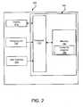
- FIGURE 2is a block diagram depicting an apparatus 200 in accordance with an example embodiment of the invention.
- the apparatus 200may be an electronic device such as a hand-portable device, a mobile phone or a Personal Digital Assistant (PDA), a Personal Computer (PC), a laptop, a desktop, a tablet computer, a wireless terminal, a communication terminal, a game console, a music player, an electronic book reader (e-book reader), a positioning device, a digital camera, a CD-, DVD or Blu-ray player, or a media player.
- PDAPersonal Digital Assistant
- PCPersonal Computer
- a laptopa desktop
- a tablet computera wireless terminal
- a communication terminala game console
- music playeran electronic book reader (e-book reader)
- a positioning devicea digital camera, a CD-, DVD or Blu-ray player, or a media player.
- the apparatus 200is a mobile computing device.
- the mobile computing device 200is illustrated as comprising the apparatus 100, a display 210, a user interface 220 and a charging unit 230.
- the display 210 and/or user interface 220may be external to the apparatus 200 but in communication with it.
- the display 210may be incorporated into the user interface 220: for example, the user interface 220 may include a touch screen display.
- the user interface 220may also comprise a manually operable control such as a button, a key, a touch pad, a joystick, a stylus, a pen, a roller, a rocker, a keypad, a keyboard or any suitable input mechanism for inputting and/or accessing information.
- a manually operable controlsuch as a button, a key, a touch pad, a joystick, a stylus, a pen, a roller, a rocker, a keypad, a keyboard or any suitable input mechanism for inputting and/or accessing information.
- Further examplesinclude a microphone, a speech recognition system, eye movement recognition system, acceleration-, tilt- and/or movement-based input systems. Therefore, the mobile computing device 200 may also comprise different kinds of sensors such as one or more gyro sensors, accelerometers, magnetometers, position sensors and/or tilt sensors.
- the mobile computing device 200 of the example of Fig. 2may also be configured to establish radio communication with another device using, for example, a Bluetooth, WiFi, radio frequency identification (RFID), or a near field communication (NFC) connection.
- RFIDradio frequency identification
- NFCnear field communication
- the charging unit 230is configured to charge a battery of the mobile computing device 200 in response to an inductive coupling with a wireless charger.
- the wireless chargerembodies one or more transmitter coils configured to produce an electromagnetic field by a flowing electrical current within the one or more coils.
- the electromagnetic fieldmay be a combination of an electric field and a magnetic field.
- the electromagnetic fieldmay only comprise a magnetic field or the magnetic field component may be significantly stronger than the electric field component.
- the electric field componentmay be more dominant than the magnetic field.
- the properties of the electromagnetic fieldmay depend, for example, on the distance between the wireless charger and the charging unit.
- the electromagnetic fieldis passed through one or more receiver coils of the mobile computing device 200, in which a current is induced by the electromagnetic field. The induced current is then used for charging the battery of the mobile computing device 200.
- the mobile computing device 200may be placed on or next to the wireless charger to initiate wireless charging.
- the charging unit 230comprises one or more receiver coils, a charging circuit operatively connected to the one or more receiver coils, and one or more operative connections to the processor 110 and/or the wireless charger.
- the charging unit 230may further be configured to communicate with the wireless charger.
- the charging unitmay be configured to transmit a signal to the wireless charger indicating, for example, the strength of the received charging field, an identifier of a receiver coil and/or charging unit, required power, and/or control data for adapting power transfer from the wireless charger.
- the charging unit 230may be configured to guide a user to place the mobile computing device in an optimal position with respect to the wireless charger.
- An optimal positionmay comprise a position in which the receiver coil captures as many field lines of the electromagnetic field as possible, for example to enable charging to proceeding as rapidly as possible.
- the charging unit 230may comprise an additional magnet configured to provide haptic feedback (e.g. a pulling force) or the processor 110 may be configured to cause providing visual, audible or any other appropriate feedback to guide a user to place the mobile computing device 200 in an optimal position with respect to the wireless charger.
- the wireless chargermay comprise a moving transmitter coil or an array of transmitter coils in which case means for guiding a user may not necessarily be needed. It should be noted that wireless charging is not limited to electromagnetic induction. In some examples wireless charging may be based on, for example, magnetic resonance, electromagnetic resonance or any other suitable method that enables charging, such as a method that effectively enables current generated to receiver circuitry.
- the mobile computing device 200may include another kind of an output device such as a tactile feedback system for presenting tactile and/or haptic information for a user.
- the tactile feedback systemmay be configured to receive control signals provided by the processor 110.
- the tactile feedback systemmay be configured to indicate a completed operation or to indicate selecting an operation, for example.
- a tactile feedback systemmay cause the mobile computing device 200 to vibrate in a certain way to inform a user of an activated and/or completed operation.
- the mobile computing device 200is configured to receive an indication of a presence of a wireless charging field such as an electromagnetic field produced by a wireless charger.
- the indication of the presence of a wireless charging fieldis received by the apparatus 100 that may be configured to receive the indication of the presence of the wireless charging field, for example, by detecting a charging state of the mobile computing device 200 by the apparatus 100, by receiving a signal from a wireless charger, or by detecting that the mobile computing device is operatively connected to the wireless charger such as placed on the wireless charger.
- Detecting the charging state of the mobile computing device 200 by the apparatus 100may comprise detecting current induced by an electromagnetic field in one or more receiver coils of the mobile computing device 200 or voltage induced across the one or more coils.
- the mobile computing device 200 of the example of Fig.2is further configured to detect a change of orientation of the mobile computing device 200 during the presence of the wireless charging field.
- the change of orientationmay be detected by the apparatus 100 by detecting activity at a discrete region different from a previous discrete region relative to the wireless charger.
- activity at a discrete regionmay comprise at least establishing radio communication between the mobile computing device 200 and an NFC tag integrated in the wireless charger and based on which the apparatus 100 detects a change of orientation.
- the change of orientationmay be detected by the apparatus 100 by detecting an absolute or a relative change of orientation of the mobile computing device 200 by one or more gyro sensors, accelerometers and/or magnetometers.
- the apparatus 100may also be configured to detect a direction of the change, for example, the apparatus 100 may be configured to detect a change in clockwise or counter clockwise direction, or a change in X-, Y- and/or Z-dimension.
- the apparatus 100is configured to detect a change of orientation of the wireless charger when the mobile computing device 200 is operatively connected to the wireless charger.
- An operative connectionmay comprise, for example, an indication that the mobile computing device 200 is placed on the wireless charger, being charged by the wireless charger or in communication with the wireless charger.
- the mobile computing device 200 of the example of Fig. 2is further configured to control an application parameter based on the detected change.
- An application parametermay be configured to affect a property of an application such as to amplify or lessen a property of the application.
- an application parametermay be configured to amplify or lessen a property perceivable by a user.
- an application parametermay be configured to affect a behavior of an application such as to change a behavior of the application or define a particular behavior of the application.
- the application parametermay comprise volume, rewinding or forwarding a song, jumping to a next or a previous song in a music player application, scrolling a list, controlling a pointer or a cursor, controlling light brightness at home, setting an alarm or any appropriate application parameter.
- Controlling the application parametermay comprise, for example, adjusting the application parameter in dependence on the detected change of orientation by the apparatus 100 or the mobile computing device 200. Adjusting the application parameter may be in dependence on a property of the detected change. For example, the degree of adjustment of the application parameter may be proportional (e.g. directly proportional or inversely proportional) to the detected change of orientation. As another example, the degree of adjustment of the application parameter may be proportional (e.g. directly proportional or inversely proportional) to the speed of the detected change of orientation or to the degree of the detected change of orientation.
- the apparatus 100may further be configured to activate an application in response to receiving an indication of the presence of the wireless charging field or based on an NFC tag.
- the apparatus 100may be configured to launch or activate a music player, an alarm clock, a web browser, an application based on a pre-defined user setting or any other appropriate application.
- the apparatus 100may be configured to associate a detected change of orientation with the activated application.
- an advantage of automatically activating or launching an applicationmay be that a user does not need to separately activate or launch an application when the mobile computing device 200 is placed on the wireless charger.
- the launched applicationmay be considered as a criterion for controlling an application parameter by the apparatus 100.
- a usermay place the mobile computing device 200 on a wireless charger, and a music player application is launched automatically.
- the apparatus 100may associate any changes of rotation with controlling the music application.
- the usermay control, for example, the volume by rotating the phone on the wireless charger.
- the apparatus 100may be configured so that rotating the mobile computing device 200 clockwise increases the volume and rotating the device counter clockwise decreases the volume.
- a usermay wish to charge the mobile computing device 200 during night time.
- the apparatus 100may be configured so that the wireless charger is considered as a clock face: first the user may place the device 200 on the wireless charger at a first location (e.g. pointing towards 12:00) and then the user may select an alarm time by rotating the mobile computing device 200 on the wireless charger.
- the apparatus 100detects the change of orientation and sets the alarm accordingly. For example, rotating the mobile computing device 200 from the first location to a second location may correspond directly to a clock face: rotating the device from pointing towards 12 o'clock to pointing towards 6 o'clock may set the alarm to 6 o'clock. Alternatively, it may be determined that the alarm is to be set to 6 hours from the current time.
- the alarmmay be set to 7 o'clock.
- the same principlemay be used for snoozing the alarm: for example, rotating the mobile computing device 200 from a first location may cause snoozing the alarm until the time corresponding the second location or by the number of minutes corresponding to the change or orientation.
- multiple rotationsmay be used to achieve a desired input.
- a first rotationmay be used for setting hours and a second rotation may be used for setting minutes. Therefore, the apparatus 100 may be configured to control application parameters in dependence on the number of rotations.
- the apparatus 100may be configured to control an application parameter with a first rotation and refine the control of the application parameter with a second rotation.
- the apparatus 100is configured to ignore a change of orientation of the mobile computing device 200 in the absence of a wireless charging field. In another example embodiment, the apparatus 100 is configured to ignore a change of orientation based on a criterion. For example, the apparatus 100 may be configured to ignore a change of orientation when a wireless charging field is present, but the apparatus 100 fails to detect a charging state.
- an advantage of controlling an application parameter during presence of a wireless charging field based on the detected changemay be that a user may intuitively control an application parameter without removing the mobile computing device 200 from the wireless charging field.
- Another advantagemay be that controlling an application based on the detected change may be limited to situations when presence of a wireless charging field is detected. In this way, a bad user experience may be avoided when the mobile computing device is in a user's pocket, for example.
- FIGURE 3illustrates an example arrangement incorporating aspects of the disclosed embodiments.
- the mobile computing device 200 of the example of Fig. 2comprising a touch screen display 210 incorporated into the user interface 220 is placed on a wireless charger 300.
- the wireless charger 300comprises a transmitter coil for producing an electromagnetic field and NFC tags 350 incorporated in the wireless charger 300.
- the mobile computing device 200is an NFC enabled device comprising a receiver coil for receiving induced current produced by the electromagnetic field.
- changing the orientation of the mobile computing device 200 to a particular direction by a particular distance or a particular anglecauses the device 200 to react in a defined way in dependence on the particular direction and the particular distance / angle when presence of a wireless charging field is detected.
- the NFC tagsare evenly distributed along a circle 310 illustrated by a dashed line. It should be noted that the dashed line is for illustrative purposes only and may not be visible to the user. Further, in some embodiments the NFC tags may not be evenly distributed and/or along a circle. It should also be noted that even though Fig. 3 only illustrates three NFC tags, a different number of NFC tags may be incorporated into the wireless charger 300. For example, the wireless charger may comprise 1 to 20 NFC tags, more than 20 NFC tags, 4, 8, 12, 16 or any appropriate number of NFC tags.
- the NFC tags 350 in the example of Fig. 3represent discrete regions that can be used for detecting a change of orientation of the mobile computing device 200.
- the NFC tags 350may be, for example, stickers that comprise microchips with aerials configured to store a limited amount of information.
- the NFC tags 350 in the example of Fig. 3may contain information on the absolute angle 330 from a reference position 320 to a current position 340.
- an NFC tag 350may be configured to indicate to the mobile computing device 200 that the current position of the device is any angle between 0 (the reference position) and 360 degrees such as 30, 90, 135 or -20, -80 or -140 degrees.
- the '+' and '-' signmay indicate the direction of orientation.
- the '+' signmay indicate a change of orientation clockwise and the '-' sign may indicate a change of orientation counter clockwise, or vice versa.
- an NFC tagmay be configured to indicate a relative change of orientation such as + / - 5, 10, 15 etc. degrees from a previous orientation.
- the NFC tags 350are configured to cause adjusting an application parameter in response to detecting movement of the mobile communication device 200 on the wireless charger.
- the NFC tagsmay be configured to cause adjusting an application parameter in response to establishing a radio connection with the mobile computing device 200, or in response to both detecting movement and establishing a radio communication with the mobile computing device 200.
- the NFC tagsmay be configured to cause adjusting an application parameter based on a criterion.
- the criterionmay comprise, for example, cause adjusting an application parameter until a predefine level and/or status is reached, by a pre-defined step, repeatedly for a pre-defined number of times, adjusting an application parameter once in response to establishing a radio connection with the mobile computing device 200, or in dependence on a charging state of the mobile computing device 200.
- an NFC tagmay be configured to cause increasing the volume by 5% in a music player application or setting an alarm to 7 am in an alarm clock application.
- Causing an application parameter to be adjustedmay comprise indicating a change of orientation of the mobile computing device 200 to the apparatus 100, which then controls the application accordingly.
- an NFC tagmay be encoded to directly control an application parameter by instructing the apparatus 100 to perform the controlling.
- the change of orientation of the mobile computing device 200is detected based on detecting activity at discrete regions on the wireless charger.
- the change of orientation of the mobile computing device 200may be based on a continuous detecting by a sensor.
- the mobile computing device 200may comprise one or more gyro sensors, accelerometers and/or magnetometers that may be used alone or in combination for detecting a change of orientation.
- FIGURES 4 and 5illustrate another example arrangement incorporating aspects of the disclosed embodiments.
- the wireless charger 300is configured to be rotated (illustrated by the arrow 410 and the angle 420) such that the relative position of the mobile computing device 200 remains the same with respect to the wireless charger 300.
- the orientation of the wireless charger 300changes, the orientation of the mobile computing device 200 also changes, and the application parameter may be controlled accordingly.
- a change of orientation of the wireless charger 300may be detected by the apparatus 100 or the apparatus 100 may be informed of the change by the wireless charger 300.
- FIGURE 5aillustrates a side view
- FIGURE 5billustrates a top view of an example implementation of a rotatable wireless charger 300.
- the wireless charger 300may be mounted with a rotatable joint element 520 to a stand 510.
- the arrangement of Figs. 5a and 5benable changing the orientation of the wireless charger 300 both vertically and horizontally.
- a rotatable wireless chargermay be implemented in several different ways and the example of Figs. 5a and 5b is just one example.
- FIGURE 6illustrates an example method 600 incorporating aspects of the previously disclosed embodiments. More specifically the example method 600 illustrates controlling an application parameter.
- the methodstarts with receiving 601 an indication of a presence of a wireless charging field.
- Receiving the indication of a presence of a wireless charging fieldmay be based on any suitable method discussed earlier such as detecting a charging state of the mobile computing device 200 by the apparatus 100 (e.g. by detecting current induced by an electromagnetic field in a receiver coil or detecting voltage induced across a receiver coil), receiving a signal from a wireless charger or detecting an operative connection with the wireless charger (e.g. detecting that the mobile computing device 200 is placed on a wireless charger.
- the method 600continues with detecting 602 a change of orientation during the presence of the wireless charging field.
- detecting a change of orientationmay comprise detecting activity at a discrete region different from a previous discrete region (e.g. an NFC tag) relative to the wireless charger, detecting a change in a relative or an absolute position of the mobile computing device 200.
- Detecting a change of orientationmay also comprise detecting a direction of the change and/or a change of orientation of the wireless charger.
- the methodthen continues with controlling 603 an application parameter based on the detected change of orientation.
- the application parametermay be controlled in dependence on the detected change such that the amount of adjusting the parameter corresponds to the amount of the detected change of orientation or is proportional to the amount of the detected change of orientation.
- the methodmay further comprise additional operations such as activating or launching an application in response to receiving an indication of the presence of the wireless charging field or an NFC tag, or ignoring a change of orientation of the mobile computing device in the absence of a wireless charging field or based on a criterion.
- a technical effect of one or more of the example embodiments disclosed hereinis intuitively controlling an application parameter when a device is on a wireless charger without removing the device from the wireless charger.
- Another technical effect of one or more of the example embodiments disclosed hereinis easier interaction with the device since the user does not need to browse through menus etc. to control an application parameter.
- Embodiments of the present inventionmay be implemented in software, hardware, application logic or a combination of software, hardware and application logic.
- the software, application logic and/or hardwaremay reside on the apparatus, a separate device or a plurality of devices. If desired, part of the software, application logic and/or hardware may reside on the apparatus, part of the software, application logic and/or hardware may reside on a separate device, and part of the software, application logic and/or hardware may reside on a plurality of devices.
- the application logic, software or an instruction setis maintained on any one of various conventional computer-readable media.
- a 'computer-readable medium'may be any media or means that can contain, store, communicate, propagate or transport the instructions for use by or in connection with an instruction execution system, apparatus, or device, such as a computer, with one example of a computer described and depicted in FIGURE 2 .
- a computer-readable mediummay comprise a computer-readable storage medium that may be any media or means that can contain or store the instructions for use by or in connection with an instruction execution system, apparatus, or device, such as a computer.
- the different functions discussed hereinmay be performed in a different order and/or concurrently with each other. Furthermore, if desired, one or more of the above-described functions may be optional or may be combined.
Landscapes
- Engineering & Computer Science (AREA)
- Computer Networks & Wireless Communication (AREA)
- Signal Processing (AREA)
- Power Engineering (AREA)
- Physics & Mathematics (AREA)
- Health & Medical Sciences (AREA)
- General Physics & Mathematics (AREA)
- General Health & Medical Sciences (AREA)
- Toxicology (AREA)
- Medical Informatics (AREA)
- Computing Systems (AREA)
- Human Computer Interaction (AREA)
- Artificial Intelligence (AREA)
- Computer Vision & Pattern Recognition (AREA)
- Theoretical Computer Science (AREA)
- Computer Security & Cryptography (AREA)
- Electromagnetism (AREA)
- Charge And Discharge Circuits For Batteries Or The Like (AREA)
- Telephone Function (AREA)
Description
- The present application relates generally to controlling an application parameter. More specifically, the present application relates to controlling an application parameter during presence of a wireless charging field.
- Electronic devices typically comprise several different kinds of applications, notifications and functionalities. Often a user needs to, for example, activate or launch applications and/or control application parameters.
US2010081473 discloses a mobile computing device ('MCD') and docking station ('dock') individually equipped with features and components that enable charging/power signals to be communicated from the dock to the MCD without use of connectors. Other embodiments provide for the MCD or the dock to identify an orientation of the MCD as retained on the docking station. As an addition or alternative, magnetic coupling may be used to maintain and/or orient the two devices in a mated position.- Various aspects of examples of the invention are set out in the claims.
- According to a first aspect of the present invention, there is provided a method comprising receiving an indication of presence of a wireless charging field, detecting a change of orientation of a device during the presence of the wireless charging field and controlling an application parameter based on the detected change.
- According to a second aspect of the present invention, there is provided an apparatus comprising a processor, memory including computer program code, the memory and the computer program code configured to, working with the processor, cause the apparatus to perform at least the following: receive an indication of presence of a wireless charging field, detect a change of orientation of a device during the presence of the wireless charging field and control an application parameter based on the detected change.
- According to a third aspect of the present invention, there is provided a computer program product comprising a computer-readable medium bearing computer program code embodied therein for use with a computer, the computer program code comprising code for receiving an indication of presence of a wireless charging field, code for detecting a change of orientation of a device during the presence of the wireless charging field and code for controlling an application parameter based on the detected change.
- According to a fourth aspect of the present invention there is provided an apparatus, comprising means for receiving an indication of presence of a wireless charging field, means for detecting a change of orientation of a device during the presence of the wireless charging field and means for controlling an application parameter based on the detected change.
- For a more complete understanding of example embodiments of the present invention, reference is now made to the following descriptions taken in connection with the accompanying drawings in which:
FIGURE 1 shows a block diagram of an example apparatus in which examples of the disclosed embodiments may be applied;FIGURE 2 shows a block diagram of another example apparatus in which examples of the disclosed embodiments may be applied;FIGURE 3 illustrate an example arrangement in which examples of the disclosed embodiments may be applied;FIGURE 4 illustrate another example arrangement in which examples of the disclosed embodiments may be applied;FIGURE 5 illustrate a further example arrangement in which examples of the disclosed embodiments may be applied;FIGURE 6 illustrate an example method incorporating aspects of examples of the invention.- Example embodiments of the present invention and its potential advantages are understood by referring to
FIGURES 1 through 6 of the drawings. - Example embodiments relate to controlling an application parameter. According to an example embodiment an indication of presence of a wireless charging field is received by an apparatus. The wireless charging field may be detected, for example, by detecting a charging state of a device, detecting current or voltage induced by an electromagnetic field or by receiving a signal from a wireless charger. In an example, during the presence of the wireless charging field a change of orientation of the device is detected and an application parameter may be controlled based on the detected change. Controlling the application parameter may comprise adjusting the application parameter in dependence of the detected change.
FIGURE 1 is a block diagram depicting anapparatus 100 operating in accordance with an example embodiment of the invention. Theapparatus 100 may be, for example, an electronic device such as a chip or a chip-set. Theapparatus 100 includes aprocessor 110 and amemory 160. In other examples, theapparatus 100 may comprise multiple processors.- In the example of
Fig. 1 , theprocessor 110 is a control unit operatively connected to read from and write to thememory 160. Theprocessor 110 may also be configured to receive control signals received via an input interface and/or theprocessor 110 may be configured to output control signals via an output interface. In an example embodiment theprocessor 110 may be configured to convert the received control signals into appropriate commands for controlling functionalities of the apparatus. - The
memory 160 storescomputer program instructions 120 which when loaded into theprocessor 110 control the operation of theapparatus 100 as explained below. In other examples, theapparatus 100 may comprise more than onememory 160 or different kinds of storage devices. Computer program instructions 120 for enabling implementations of example embodiments of the invention or a part of such computer program instructions may be loaded onto theapparatus 100 by the manufacturer of theapparatus 100, by a user of theapparatus 100, or by theapparatus 100 itself based on a download program, or the instructions can be pushed to theapparatus 100 by an external device. The computer program instructions may arrive at theapparatus 100 via an electromagnetic carrier signal or be copied from a physical entity such as a computer program product, a memory device or a record medium such as a Compact Disc (CD), a Compact Disc Read-Only Memory (CD-ROM), a Digital Versatile Disk (DVD) or a Blu-ray disk.FIGURE 2 is a block diagram depicting anapparatus 200 in accordance with an example embodiment of the invention. Theapparatus 200 may be an electronic device such as a hand-portable device, a mobile phone or a Personal Digital Assistant (PDA), a Personal Computer (PC), a laptop, a desktop, a tablet computer, a wireless terminal, a communication terminal, a game console, a music player, an electronic book reader (e-book reader), a positioning device, a digital camera, a CD-, DVD or Blu-ray player, or a media player. In the examples ofFigs. 2 to 4 it is assumed that theapparatus 200 is a mobile computing device.- In the example of
Fig.2 , themobile computing device 200 is illustrated as comprising theapparatus 100, adisplay 210, a user interface 220 and acharging unit 230. However, thedisplay 210 and/or user interface 220 may be external to theapparatus 200 but in communication with it. In some examples thedisplay 210 may be incorporated into the user interface 220: for example, the user interface 220 may include a touch screen display. - Additionally or alternatively, the user interface 220 may also comprise a manually operable control such as a button, a key, a touch pad, a joystick, a stylus, a pen, a roller, a rocker, a keypad, a keyboard or any suitable input mechanism for inputting and/or accessing information. Further examples include a microphone, a speech recognition system, eye movement recognition system, acceleration-, tilt- and/or movement-based input systems. Therefore, the
mobile computing device 200 may also comprise different kinds of sensors such as one or more gyro sensors, accelerometers, magnetometers, position sensors and/or tilt sensors. - The
mobile computing device 200 of the example ofFig. 2 may also be configured to establish radio communication with another device using, for example, a Bluetooth, WiFi, radio frequency identification (RFID), or a near field communication (NFC) connection. In the example ofFig. 2 it is assumed that themobile computing device 200 is at least NFC enabled. - The
charging unit 230 is configured to charge a battery of themobile computing device 200 in response to an inductive coupling with a wireless charger. In this example the wireless charger embodies one or more transmitter coils configured to produce an electromagnetic field by a flowing electrical current within the one or more coils. The electromagnetic field may be a combination of an electric field and a magnetic field. In some examples the electromagnetic field may only comprise a magnetic field or the magnetic field component may be significantly stronger than the electric field component. In some examples, the electric field component may be more dominant than the magnetic field. The properties of the electromagnetic field may depend, for example, on the distance between the wireless charger and the charging unit. The electromagnetic field is passed through one or more receiver coils of themobile computing device 200, in which a current is induced by the electromagnetic field. The induced current is then used for charging the battery of themobile computing device 200. In some examples themobile computing device 200 may be placed on or next to the wireless charger to initiate wireless charging. - In an example embodiment, the
charging unit 230 comprises one or more receiver coils, a charging circuit operatively connected to the one or more receiver coils, and one or more operative connections to theprocessor 110 and/or the wireless charger. - The
charging unit 230 may further be configured to communicate with the wireless charger. For example, the charging unit may be configured to transmit a signal to the wireless charger indicating, for example, the strength of the received charging field, an identifier of a receiver coil and/or charging unit, required power, and/or control data for adapting power transfer from the wireless charger. - In some example embodiments the
charging unit 230 may be configured to guide a user to place the mobile computing device in an optimal position with respect to the wireless charger. An optimal position may comprise a position in which the receiver coil captures as many field lines of the electromagnetic field as possible, for example to enable charging to proceeding as rapidly as possible. For example, the chargingunit 230 may comprise an additional magnet configured to provide haptic feedback (e.g. a pulling force) or theprocessor 110 may be configured to cause providing visual, audible or any other appropriate feedback to guide a user to place themobile computing device 200 in an optimal position with respect to the wireless charger. However, in some example embodiments the wireless charger may comprise a moving transmitter coil or an array of transmitter coils in which case means for guiding a user may not necessarily be needed. It should be noted that wireless charging is not limited to electromagnetic induction. In some examples wireless charging may be based on, for example, magnetic resonance, electromagnetic resonance or any other suitable method that enables charging, such as a method that effectively enables current generated to receiver circuitry. - Referring back to the example of
Fig.2 , in addition to a display, themobile computing device 200 may include another kind of an output device such as a tactile feedback system for presenting tactile and/or haptic information for a user. The tactile feedback system may be configured to receive control signals provided by theprocessor 110. The tactile feedback system may be configured to indicate a completed operation or to indicate selecting an operation, for example. In an example embodiment a tactile feedback system may cause themobile computing device 200 to vibrate in a certain way to inform a user of an activated and/or completed operation. - In the example of
Fig. 2 , themobile computing device 200 is configured to receive an indication of a presence of a wireless charging field such as an electromagnetic field produced by a wireless charger. The indication of the presence of a wireless charging field is received by theapparatus 100 that may be configured to receive the indication of the presence of the wireless charging field, for example, by detecting a charging state of themobile computing device 200 by theapparatus 100, by receiving a signal from a wireless charger, or by detecting that the mobile computing device is operatively connected to the wireless charger such as placed on the wireless charger. Detecting the charging state of themobile computing device 200 by theapparatus 100 may comprise detecting current induced by an electromagnetic field in one or more receiver coils of themobile computing device 200 or voltage induced across the one or more coils. - The
mobile computing device 200 of the example ofFig.2 is further configured to detect a change of orientation of themobile computing device 200 during the presence of the wireless charging field. The change of orientation may be detected by theapparatus 100 by detecting activity at a discrete region different from a previous discrete region relative to the wireless charger. For example, activity at a discrete region may comprise at least establishing radio communication between themobile computing device 200 and an NFC tag integrated in the wireless charger and based on which theapparatus 100 detects a change of orientation. As another example, the change of orientation may be detected by theapparatus 100 by detecting an absolute or a relative change of orientation of themobile computing device 200 by one or more gyro sensors, accelerometers and/or magnetometers. Theapparatus 100 may also be configured to detect a direction of the change, for example, theapparatus 100 may be configured to detect a change in clockwise or counter clockwise direction, or a change in X-, Y- and/or Z-dimension. In an example embodiment, theapparatus 100 is configured to detect a change of orientation of the wireless charger when themobile computing device 200 is operatively connected to the wireless charger. An operative connection may comprise, for example, an indication that themobile computing device 200 is placed on the wireless charger, being charged by the wireless charger or in communication with the wireless charger. - The
mobile computing device 200 of the example ofFig. 2 is further configured to control an application parameter based on the detected change. An application parameter may be configured to affect a property of an application such as to amplify or lessen a property of the application. For example, an application parameter may be configured to amplify or lessen a property perceivable by a user. As a further example, an application parameter may be configured to affect a behavior of an application such as to change a behavior of the application or define a particular behavior of the application. As an example, the application parameter may comprise volume, rewinding or forwarding a song, jumping to a next or a previous song in a music player application, scrolling a list, controlling a pointer or a cursor, controlling light brightness at home, setting an alarm or any appropriate application parameter. - Controlling the application parameter may comprise, for example, adjusting the application parameter in dependence on the detected change of orientation by the
apparatus 100 or themobile computing device 200. Adjusting the application parameter may be in dependence on a property of the detected change. For example, the degree of adjustment of the application parameter may be proportional (e.g. directly proportional or inversely proportional) to the detected change of orientation. As another example, the degree of adjustment of the application parameter may be proportional (e.g. directly proportional or inversely proportional) to the speed of the detected change of orientation or to the degree of the detected change of orientation. - In an example, the
apparatus 100 may further be configured to activate an application in response to receiving an indication of the presence of the wireless charging field or based on an NFC tag. For example, theapparatus 100 may be configured to launch or activate a music player, an alarm clock, a web browser, an application based on a pre-defined user setting or any other appropriate application. Theapparatus 100 may be configured to associate a detected change of orientation with the activated application. - Without limiting the scope of the claims, an advantage of automatically activating or launching an application may be that a user does not need to separately activate or launch an application when the
mobile computing device 200 is placed on the wireless charger. A further advantage may be that the launched application may be considered as a criterion for controlling an application parameter by theapparatus 100. For example, a user may place themobile computing device 200 on a wireless charger, and a music player application is launched automatically. As a consequence, theapparatus 100 may associate any changes of rotation with controlling the music application. The user may control, for example, the volume by rotating the phone on the wireless charger. In this example, theapparatus 100 may be configured so that rotating themobile computing device 200 clockwise increases the volume and rotating the device counter clockwise decreases the volume. - As another example, a user may wish to charge the
mobile computing device 200 during night time. Theapparatus 100 may be configured so that the wireless charger is considered as a clock face: first the user may place thedevice 200 on the wireless charger at a first location (e.g. pointing towards 12:00) and then the user may select an alarm time by rotating themobile computing device 200 on the wireless charger. Theapparatus 100 detects the change of orientation and sets the alarm accordingly. For example, rotating themobile computing device 200 from the first location to a second location may correspond directly to a clock face: rotating the device from pointing towards 12 o'clock to pointing towards 6 o'clock may set the alarm to 6 o'clock. Alternatively, it may be determined that the alarm is to be set to 6 hours from the current time. For example, assuming it is 1 o'clock when themobile computing device 200 is placed at the first location and rotated towards 6 o'clock, the alarm may be set to 7 o'clock. The same principle may be used for snoozing the alarm: for example, rotating themobile computing device 200 from a first location may cause snoozing the alarm until the time corresponding the second location or by the number of minutes corresponding to the change or orientation. In some examples, multiple rotations may be used to achieve a desired input. For example, in terms of setting an alarm, a first rotation may be used for setting hours and a second rotation may be used for setting minutes. Therefore, theapparatus 100 may be configured to control application parameters in dependence on the number of rotations. For example, theapparatus 100 may be configured to control an application parameter with a first rotation and refine the control of the application parameter with a second rotation. - According to an example embodiment, the
apparatus 100 is configured to ignore a change of orientation of themobile computing device 200 in the absence of a wireless charging field. In another example embodiment, theapparatus 100 is configured to ignore a change of orientation based on a criterion. For example, theapparatus 100 may be configured to ignore a change of orientation when a wireless charging field is present, but theapparatus 100 fails to detect a charging state. - Without limiting the scope of the claims, an advantage of controlling an application parameter during presence of a wireless charging field based on the detected change may be that a user may intuitively control an application parameter without removing the
mobile computing device 200 from the wireless charging field. Another advantage may be that controlling an application based on the detected change may be limited to situations when presence of a wireless charging field is detected. In this way, a bad user experience may be avoided when the mobile computing device is in a user's pocket, for example. FIGURE 3 illustrates an example arrangement incorporating aspects of the disclosed embodiments. In this example, themobile computing device 200 of the example ofFig. 2 comprising atouch screen display 210 incorporated into the user interface 220 is placed on awireless charger 300. Thewireless charger 300 comprises a transmitter coil for producing an electromagnetic field andNFC tags 350 incorporated in thewireless charger 300. Themobile computing device 200 is an NFC enabled device comprising a receiver coil for receiving induced current produced by the electromagnetic field. In this example, changing the orientation of themobile computing device 200 to a particular direction by a particular distance or a particular angle, causes thedevice 200 to react in a defined way in dependence on the particular direction and the particular distance / angle when presence of a wireless charging field is detected.- In the example of
Fig. 3 , the NFC tags are evenly distributed along acircle 310 illustrated by a dashed line. It should be noted that the dashed line is for illustrative purposes only and may not be visible to the user. Further, in some embodiments the NFC tags may not be evenly distributed and/or along a circle. It should also be noted that even thoughFig. 3 only illustrates three NFC tags, a different number of NFC tags may be incorporated into thewireless charger 300. For example, the wireless charger may comprise 1 to 20 NFC tags, more than 20 NFC tags, 4, 8, 12, 16 or any appropriate number of NFC tags. - The NFC tags 350 in the example of
Fig. 3 represent discrete regions that can be used for detecting a change of orientation of themobile computing device 200. The NFC tags 350 may be, for example, stickers that comprise microchips with aerials configured to store a limited amount of information. The NFC tags 350 in the example ofFig. 3 may contain information on theabsolute angle 330 from areference position 320 to a current position 340. For example, anNFC tag 350 may be configured to indicate to themobile computing device 200 that the current position of the device is any angle between 0 (the reference position) and 360 degrees such as 30, 90, 135 or -20, -80 or -140 degrees. In this example the '+' and '-' sign may indicate the direction of orientation. For example, the '+' sign may indicate a change of orientation clockwise and the '-' sign may indicate a change of orientation counter clockwise, or vice versa. Alternatively, an NFC tag may be configured to indicate a relative change of orientation such as + / - 5, 10, 15 etc. degrees from a previous orientation. - In the example of
Fig. 3 , the NFC tags 350 are configured to cause adjusting an application parameter in response to detecting movement of themobile communication device 200 on the wireless charger. In other examples, the NFC tags may be configured to cause adjusting an application parameter in response to establishing a radio connection with themobile computing device 200, or in response to both detecting movement and establishing a radio communication with themobile computing device 200. The NFC tags may be configured to cause adjusting an application parameter based on a criterion. The criterion may comprise, for example, cause adjusting an application parameter until a predefine level and/or status is reached, by a pre-defined step, repeatedly for a pre-defined number of times, adjusting an application parameter once in response to establishing a radio connection with themobile computing device 200, or in dependence on a charging state of themobile computing device 200. For example, an NFC tag may be configured to cause increasing the volume by 5% in a music player application or setting an alarm to 7 am in an alarm clock application. Causing an application parameter to be adjusted may comprise indicating a change of orientation of themobile computing device 200 to theapparatus 100, which then controls the application accordingly. As another example, an NFC tag may be encoded to directly control an application parameter by instructing theapparatus 100 to perform the controlling. - In the example of
Fig. 3 the change of orientation of themobile computing device 200 is detected based on detecting activity at discrete regions on the wireless charger. In some examples the change of orientation of themobile computing device 200 may be based on a continuous detecting by a sensor. For example, themobile computing device 200 may comprise one or more gyro sensors, accelerometers and/or magnetometers that may be used alone or in combination for detecting a change of orientation. FIGURES 4 and 5 illustrate another example arrangement incorporating aspects of the disclosed embodiments. In these examples thewireless charger 300 is configured to be rotated (illustrated by thearrow 410 and the angle 420) such that the relative position of themobile computing device 200 remains the same with respect to thewireless charger 300. In other words, when the orientation of thewireless charger 300 changes, the orientation of themobile computing device 200 also changes, and the application parameter may be controlled accordingly. A change of orientation of thewireless charger 300 may be detected by theapparatus 100 or theapparatus 100 may be informed of the change by thewireless charger 300.FIGURE 5a illustrates a side view andFIGURE 5b illustrates a top view of an example implementation of arotatable wireless charger 300. Thewireless charger 300 may be mounted with a rotatablejoint element 520 to astand 510. As illustrated byreference numbers Figs. 5a and 5b enable changing the orientation of thewireless charger 300 both vertically and horizontally. It should be noted that a rotatable wireless charger may be implemented in several different ways and the example ofFigs. 5a and 5b is just one example.FIGURE 6 illustrates anexample method 600 incorporating aspects of the previously disclosed embodiments. More specifically theexample method 600 illustrates controlling an application parameter.- The method starts with receiving 601 an indication of a presence of a wireless charging field. Receiving the indication of a presence of a wireless charging field may be based on any suitable method discussed earlier such as detecting a charging state of the
mobile computing device 200 by the apparatus 100 (e.g. by detecting current induced by an electromagnetic field in a receiver coil or detecting voltage induced across a receiver coil), receiving a signal from a wireless charger or detecting an operative connection with the wireless charger (e.g. detecting that themobile computing device 200 is placed on a wireless charger. - The
method 600 continues with detecting 602 a change of orientation during the presence of the wireless charging field. As discussed earlier, detecting a change of orientation may comprise detecting activity at a discrete region different from a previous discrete region (e.g. an NFC tag) relative to the wireless charger, detecting a change in a relative or an absolute position of themobile computing device 200. Detecting a change of orientation may also comprise detecting a direction of the change and/or a change of orientation of the wireless charger. - The method then continues with controlling 603 an application parameter based on the detected change of orientation. For example, the application parameter may be controlled in dependence on the detected change such that the amount of adjusting the parameter corresponds to the amount of the detected change of orientation or is proportional to the amount of the detected change of orientation.
- The method may further comprise additional operations such as activating or launching an application in response to receiving an indication of the presence of the wireless charging field or an NFC tag, or ignoring a change of orientation of the mobile computing device in the absence of a wireless charging field or based on a criterion.
- Without in any way limiting the scope, interpretation, or application of the claims appearing below, a technical effect of one or more of the example embodiments disclosed herein is intuitively controlling an application parameter when a device is on a wireless charger without removing the device from the wireless charger. Another technical effect of one or more of the example embodiments disclosed herein is easier interaction with the device since the user does not need to browse through menus etc. to control an application parameter.
- Embodiments of the present invention may be implemented in software, hardware, application logic or a combination of software, hardware and application logic. The software, application logic and/or hardware may reside on the apparatus, a separate device or a plurality of devices. If desired, part of the software, application logic and/or hardware may reside on the apparatus, part of the software, application logic and/or hardware may reside on a separate device, and part of the software, application logic and/or hardware may reside on a plurality of devices. In an example embodiment, the application logic, software or an instruction set is maintained on any one of various conventional computer-readable media. In the context of this document, a 'computer-readable medium' may be any media or means that can contain, store, communicate, propagate or transport the instructions for use by or in connection with an instruction execution system, apparatus, or device, such as a computer, with one example of a computer described and depicted in
FIGURE 2 . A computer-readable medium may comprise a computer-readable storage medium that may be any media or means that can contain or store the instructions for use by or in connection with an instruction execution system, apparatus, or device, such as a computer. - If desired, the different functions discussed herein may be performed in a different order and/or concurrently with each other. Furthermore, if desired, one or more of the above-described functions may be optional or may be combined.
- Although various aspects of the invention are set out in the independent claims, other aspects of the invention comprise other combinations of features from the described embodiments and/or the dependent claims with the features of the independent claims, and not solely the combinations explicitly set out in the claims.
- It is also noted herein that while the above describes example embodiments of the invention, these descriptions should not be viewed in a limiting sense. Rather, there are several variations and modifications which may be made without departing from the scope of the present invention as defined in the appended claims.
Claims (15)
- An apparatus (100), comprising:a processor (110),memory (160) including computer program code (120), the memory (160) and the computer program code (120) configured to, working with the processor (110), cause the apparatus (100) to perform at least the following:- receive an indication of presence of a wireless charging field;- detect a direction of a change of orientation of a device (200) during the presence of the wireless charging field; and- control an application parameter based on the detected change.
- An apparatus according to claim 1, wherein the memory (160) and the computer program code (120) are configured to, working with the processor (110), receive the indication of the presence of the wireless charging field by detecting a charging state of the device (200).
- An apparatus according to claim 2, wherein the memory (160) and the computer program code (120) are configured to, working with the processor (110), detect the charging state of the device (200) by detecting current induced by an electromagnetic field in a receiver coil or detecting voltage induced across a receiver coil.
- An apparatus according claim 1, wherein the memory (160) and the computer program code (120) are configured to, working with the processor (110), receive the indication of the presence of the wireless charging field by receiving a signal from a wireless charger (300).
- An apparatus according to any preceding claim, wherein the memory (160) and the computer program code (120) are configured to, working with the processor (110), detect the change of orientation of the device (200) based on a continuous detecting by one or more sensors or by detecting activity at a discrete region (350) different from a previous discrete region (350) relative to a wireless charger (300).
- An apparatus according to claim 5, wherein the memory (160) and the computer program code (120) are configured to, working with the processor (110), detect activity at a discrete region (350), wherein the activity at the discrete region (350) comprises at least establishing a radio communication between the device (200) and a near field communication tag (350) integrated in the wireless charger (300).
- An apparatus according to any preceding claim, wherein the memory (160) and the computer program code (120) are configured to, working with the processor (110), detect the change of orientation of the device (200) by detecting a change of a relative or an absolute position of the device (200).
- An apparatus according to any preceding claim, wherein the memory (160) and the computer program code (120) are configured to, working with the processor (110), detect the direction of the change in clockwise or counter clockwise direction, or in X-, Y- and/or Z-dimension.
- An apparatus according to any preceding claim, wherein the memory (160) and the computer program code (120) are configured to, working with the processor (110), detect the change of orientation of the device by detecting a change of orientation of the wireless charger (300) when the device is operatively connected to a wireless charger (300).
- An apparatus according to any preceding claim, wherein the memory (160) and the computer program code (120) are configured to, working with the processor, adjust the application parameter in dependence on the detected change of orientation of the device.
- An apparatus according to any preceding claim, wherein the memory (160) and the computer program code (120) are configured to, working with the processor, activate an application in response to receiving an indication of the presence of the wireless charging field.
- An apparatus according to any preceding claim, wherein the device (200) comprises the apparatus (100).
- An apparatus according to any preceding claim, wherein the application parameter comprises controlling volume, rewinding a song, forwarding a song, jumping to a next song, jumping to a previous song, scrolling a list, controlling a pointer / cursor, controlling light brightness at home, setting an alarm or snoozing an alarm.
- A method comprising:- receiving (601) an indication of presence of a wireless charging field;- detecting (602) a direction of a change of orientation of a device during the presence of the wireless charging field; and- controlling (603) an application parameter based on the detected change.
- A computer program product comprising a computer-readable medium bearing computer program code embodied therein for use with a computer, the computer program code comprising:code for receiving an indication of presence of a wireless charging field;code for detecting a direction of a change of orientation of a device during the presence of the wireless charging field; andcode for controlling an application parameter based on the detected change.
Priority Applications (6)
| Application Number | Priority Date | Filing Date | Title |
|---|---|---|---|
| EP12199409.9AEP2750361B1 (en) | 2012-12-27 | 2012-12-27 | Controlling an application parameter |
| PCT/FI2013/051141WO2014102450A1 (en) | 2012-12-27 | 2013-12-05 | Controlling an application parameter |
| US14/758,038US9722455B2 (en) | 2012-12-27 | 2013-12-05 | Controlling an application parameter |
| JP2015550123AJP6105749B2 (en) | 2012-12-27 | 2013-12-05 | Control application parameters |
| CN201380072512.2ACN104969536A (en) | 2012-12-27 | 2013-12-05 | Control application parameters |
| TW102148412ATWI530047B (en) | 2012-12-27 | 2013-12-26 | Means for enabling control of application parameters, methods for controlling application parameters, and related computer program products |
Applications Claiming Priority (1)
| Application Number | Priority Date | Filing Date | Title |
|---|---|---|---|
| EP12199409.9AEP2750361B1 (en) | 2012-12-27 | 2012-12-27 | Controlling an application parameter |
Publications (2)
| Publication Number | Publication Date |
|---|---|
| EP2750361A1 EP2750361A1 (en) | 2014-07-02 |
| EP2750361B1true EP2750361B1 (en) | 2015-10-21 |
Family
ID=47552831
Family Applications (1)
| Application Number | Title | Priority Date | Filing Date |
|---|---|---|---|
| EP12199409.9AActiveEP2750361B1 (en) | 2012-12-27 | 2012-12-27 | Controlling an application parameter |
Country Status (6)
| Country | Link |
|---|---|
| US (1) | US9722455B2 (en) |
| EP (1) | EP2750361B1 (en) |
| JP (1) | JP6105749B2 (en) |
| CN (1) | CN104969536A (en) |
| TW (1) | TWI530047B (en) |
| WO (1) | WO2014102450A1 (en) |
Cited By (1)
| Publication number | Priority date | Publication date | Assignee | Title |
|---|---|---|---|---|
| CN108886860A (en)* | 2016-03-04 | 2018-11-23 | 飞利浦照明控股有限公司 | Control system for controlling lighting equipment arranged to provide functional and/or mood lighting |
Families Citing this family (15)
| Publication number | Priority date | Publication date | Assignee | Title |
|---|---|---|---|---|
| EP3117685B1 (en)* | 2014-01-30 | 2018-05-30 | Hewlett-Packard Development Company, L.P. | Wireless power alignment |
| US20150365737A1 (en)* | 2014-06-11 | 2015-12-17 | Enovate Medical, Llc | Wireless transfer station with display |
| EP3035156A1 (en)* | 2014-12-15 | 2016-06-22 | Thomson Licensing | Method and apparatus for remotely controlling an electronic device |
| US9685802B1 (en) | 2015-04-29 | 2017-06-20 | Verily Life Sciences, LLC | Detection of accessory presence and orientation |
| EP3223543B1 (en)* | 2016-03-23 | 2018-05-02 | Mitel Networks Corporation | Portable device |
| KR102529747B1 (en) | 2016-05-23 | 2023-05-08 | 삼성에스디아이 주식회사 | Wireless charging device and charging method thereof |
| CN106101339A (en)* | 2016-06-01 | 2016-11-09 | 广东欧珀移动通信有限公司 | A casing and a mobile terminal |
| JP7126544B2 (en) | 2017-07-07 | 2022-08-26 | ニューロダーム リミテッド | Vial adapter, method and filling system for filling a reservoir of a drug delivery device with a flowable drug using the vial adapter |
| US20230123806A1 (en) | 2017-07-07 | 2023-04-20 | Neuroderm, Ltd. | Device for subcutaneous delivery of fluid medicament |
| US10818392B1 (en) | 2017-08-10 | 2020-10-27 | Enovate Medical, Llc | Battery and workstation monitoring system and display |
| EP3644475A1 (en)* | 2018-10-24 | 2020-04-29 | Koninklijke Philips N.V. | A power transfer apparatus and method therefor |
| US11979038B2 (en)* | 2019-03-07 | 2024-05-07 | Google Llc | Wireless charging alignment |
| FR3094103B1 (en)* | 2019-03-18 | 2021-07-23 | Electricite De France | Power consumption display system, charger for such a system, method and program for implementing such a system |
| CN110996197B (en)* | 2019-11-15 | 2021-05-28 | 歌尔股份有限公司 | Control method of audio device, and storage medium |
| US11611245B2 (en)* | 2020-08-13 | 2023-03-21 | Mediatek Singapore Pte. Ltd. | Wirelessly charging mobile phone via notebook touchpad |
Family Cites Families (15)
| Publication number | Priority date | Publication date | Assignee | Title |
|---|---|---|---|---|
| EP2109915B1 (en) | 2007-01-08 | 2013-12-04 | Apple Inc. | Antenna insert |
| US8248024B2 (en)* | 2008-08-15 | 2012-08-21 | Microsoft Corporation | Advanced inductive charging pad for portable devices |
| WO2010020895A2 (en) | 2008-08-18 | 2010-02-25 | Nxp B.V. | A mobile device to control a charge pad system |
| US8385822B2 (en)* | 2008-09-26 | 2013-02-26 | Hewlett-Packard Development Company, L.P. | Orientation and presence detection for use in configuring operations of computing devices in docked environments |
| JP2010206866A (en)* | 2009-02-27 | 2010-09-16 | Panasonic Corp | Electronic equipment and charger |
| JP5451174B2 (en)* | 2009-05-14 | 2014-03-26 | キヤノン株式会社 | Charger and control method thereof |
| US9590444B2 (en)* | 2009-11-30 | 2017-03-07 | Broadcom Corporation | Device with integrated wireless power receiver configured to make a charging determination based on a level of battery life and charging efficiency |
| US10141770B2 (en)* | 2011-01-18 | 2018-11-27 | Mojo Mobility, Inc. | Powering and/or charging with a plurality of protocols |
| WO2012111873A1 (en) | 2011-02-18 | 2012-08-23 | 엘지전자 주식회사 | Method and device for wireless charging |
| JP5744589B2 (en)* | 2011-03-25 | 2015-07-08 | 京セラ株式会社 | Portable electronic device, notification control method, and notification control program |
| US8645604B2 (en)* | 2011-03-25 | 2014-02-04 | Apple Inc. | Device orientation based docking functions |
| KR102065021B1 (en)* | 2012-01-24 | 2020-01-10 | 필립스 아이피 벤쳐스 비.브이. | Wireless power control system |
| US20140021798A1 (en)* | 2012-07-17 | 2014-01-23 | Witricity Corporation | Wireless energy transfer with repeater resonators |
| US9318905B2 (en)* | 2012-11-09 | 2016-04-19 | City University Of Hong Kong | Wireless optical charging and power supply |
| US10391871B2 (en)* | 2014-01-10 | 2019-08-27 | Witricity Corporation | Controlling current flow path in wireless electric vehicle charging systems for mitigating RF radiated emissions |
- 2012
- 2012-12-27EPEP12199409.9Apatent/EP2750361B1/enactiveActive
- 2013
- 2013-12-05WOPCT/FI2013/051141patent/WO2014102450A1/enactiveApplication Filing
- 2013-12-05CNCN201380072512.2Apatent/CN104969536A/enactivePending
- 2013-12-05USUS14/758,038patent/US9722455B2/enactiveActive
- 2013-12-05JPJP2015550123Apatent/JP6105749B2/enactiveActive
- 2013-12-26TWTW102148412Apatent/TWI530047B/enactive
Cited By (2)
| Publication number | Priority date | Publication date | Assignee | Title |
|---|---|---|---|---|
| CN108886860A (en)* | 2016-03-04 | 2018-11-23 | 飞利浦照明控股有限公司 | Control system for controlling lighting equipment arranged to provide functional and/or mood lighting |
| CN108886860B (en)* | 2016-03-04 | 2021-03-12 | 飞利浦照明控股有限公司 | Control system for controlling lighting equipment arranged to provide functional and/or mood lighting |
Also Published As
| Publication number | Publication date |
|---|---|
| TWI530047B (en) | 2016-04-11 |
| TW201433042A (en) | 2014-08-16 |
| US20150357862A1 (en) | 2015-12-10 |
| EP2750361A1 (en) | 2014-07-02 |
| JP6105749B2 (en) | 2017-03-29 |
| US9722455B2 (en) | 2017-08-01 |
| JP2016509823A (en) | 2016-03-31 |
| CN104969536A (en) | 2015-10-07 |
| WO2014102450A1 (en) | 2014-07-03 |
Similar Documents
| Publication | Publication Date | Title |
|---|---|---|
| EP2750361B1 (en) | Controlling an application parameter | |
| US9357396B2 (en) | Terminal device | |
| US20130281155A1 (en) | System, electronic device, and charger | |
| US10341480B2 (en) | Wearable device paired with mobile terminal and operating method thereof | |
| US20140187148A1 (en) | Near field communication method and apparatus using sensor context | |
| KR20150081140A (en) | Wearable device and operation method thereof | |
| KR20140126140A (en) | Mobile apparatus providing with changed-shortcut icon responding to status of mobile apparatus and control method thereof | |
| KR20170098124A (en) | Electronic device and accessory apparatus and information display method using the same | |
| EP2820830B1 (en) | Methods of responding to an orientation or motion of a portable electronic device, and related devices | |
| KR20150061420A (en) | Smart watch and operation method thereof | |
| JP2013201863A (en) | System, electronic device and charger | |
| JP5950546B2 (en) | Portable electronic device, method and program | |
| KR20160026135A (en) | Electronic device and method of sending a message using electronic device | |
| US20150102670A1 (en) | Method for operating booting and electronic device thereof | |
| US9513616B2 (en) | System and method for controlling functions on electronic devices | |
| WO2016068192A1 (en) | Electronic device, control method, and control program | |
| EP2750075A1 (en) | Activating a charging lock | |
| JP2013198050A (en) | Mobile electronic apparatus and charging system | |
| JP2013080353A (en) | Device, method, and program | |
| CA2751830C (en) | System and method for controlling functions on electronic devices | |
| JP6141491B2 (en) | Portable electronic device, method and program | |
| JP2013114306A (en) | Electronic device, control method and program | |
| KR20150021243A (en) | Electronic device and method for controlling at least one of vibration and sound |
Legal Events
| Date | Code | Title | Description |
|---|---|---|---|
| 17P | Request for examination filed | Effective date:20121227 | |
| AK | Designated contracting states | Kind code of ref document:A1 Designated state(s):AL AT BE BG CH CY CZ DE DK EE ES FI FR GB GR HR HU IE IS IT LI LT LU LV MC MK MT NL NO PL PT RO RS SE SI SK SM TR | |
| AX | Request for extension of the european patent | Extension state:BA ME | |
| PUAI | Public reference made under article 153(3) epc to a published international application that has entered the european phase | Free format text:ORIGINAL CODE: 0009012 | |
| R17P | Request for examination filed (corrected) | Effective date:20141230 | |
| RBV | Designated contracting states (corrected) | Designated state(s):AL AT BE BG CH CY CZ DE DK EE ES FI FR GB GR HR HU IE IS IT LI LT LU LV MC MK MT NL NO PL PT RO RS SE SI SK SM TR | |
| RAP1 | Party data changed (applicant data changed or rights of an application transferred) | Owner name:NOKIA TECHNOLOGIES OY | |
| GRAP | Despatch of communication of intention to grant a patent | Free format text:ORIGINAL CODE: EPIDOSNIGR1 | |
| INTG | Intention to grant announced | Effective date:20150513 | |
| GRAS | Grant fee paid | Free format text:ORIGINAL CODE: EPIDOSNIGR3 | |
| GRAA | (expected) grant | Free format text:ORIGINAL CODE: 0009210 | |
| AK | Designated contracting states | Kind code of ref document:B1 Designated state(s):AL AT BE BG CH CY CZ DE DK EE ES FI FR GB GR HR HU IE IS IT LI LT LU LV MC MK MT NL NO PL PT RO RS SE SI SK SM TR | |
| REG | Reference to a national code | Ref country code:GB Ref legal event code:FG4D | |
| REG | Reference to a national code | Ref country code:CH Ref legal event code:EP | |
| REG | Reference to a national code | Ref country code:FR Ref legal event code:PLFP Year of fee payment:4 | |
| REG | Reference to a national code | Ref country code:AT Ref legal event code:REF Ref document number:757289 Country of ref document:AT Kind code of ref document:T Effective date:20151115 | |
| REG | Reference to a national code | Ref country code:IE Ref legal event code:FG4D | |
| REG | Reference to a national code | Ref country code:DE Ref legal event code:R096 Ref document number:602012011766 Country of ref document:DE | |
| REG | Reference to a national code | Ref country code:NL Ref legal event code:FP | |
| REG | Reference to a national code | Ref country code:LT Ref legal event code:MG4D | |
| REG | Reference to a national code | Ref country code:AT Ref legal event code:MK05 Ref document number:757289 Country of ref document:AT Kind code of ref document:T Effective date:20151021 | |
| PG25 | Lapsed in a contracting state [announced via postgrant information from national office to epo] | Ref country code:IT Free format text:LAPSE BECAUSE OF FAILURE TO SUBMIT A TRANSLATION OF THE DESCRIPTION OR TO PAY THE FEE WITHIN THE PRESCRIBED TIME-LIMIT Effective date:20151021 Ref country code:ES Free format text:LAPSE BECAUSE OF FAILURE TO SUBMIT A TRANSLATION OF THE DESCRIPTION OR TO PAY THE FEE WITHIN THE PRESCRIBED TIME-LIMIT Effective date:20151021 Ref country code:HR Free format text:LAPSE BECAUSE OF FAILURE TO SUBMIT A TRANSLATION OF THE DESCRIPTION OR TO PAY THE FEE WITHIN THE PRESCRIBED TIME-LIMIT Effective date:20151021 Ref country code:NO Free format text:LAPSE BECAUSE OF FAILURE TO SUBMIT A TRANSLATION OF THE DESCRIPTION OR TO PAY THE FEE WITHIN THE PRESCRIBED TIME-LIMIT Effective date:20160121 Ref country code:LT Free format text:LAPSE BECAUSE OF FAILURE TO SUBMIT A TRANSLATION OF THE DESCRIPTION OR TO PAY THE FEE WITHIN THE PRESCRIBED TIME-LIMIT Effective date:20151021 Ref country code:IS Free format text:LAPSE BECAUSE OF FAILURE TO SUBMIT A TRANSLATION OF THE DESCRIPTION OR TO PAY THE FEE WITHIN THE PRESCRIBED TIME-LIMIT Effective date:20160221 | |
| PG25 | Lapsed in a contracting state [announced via postgrant information from national office to epo] | Ref country code:FI Free format text:LAPSE BECAUSE OF FAILURE TO SUBMIT A TRANSLATION OF THE DESCRIPTION OR TO PAY THE FEE WITHIN THE PRESCRIBED TIME-LIMIT Effective date:20151021 Ref country code:RS Free format text:LAPSE BECAUSE OF FAILURE TO SUBMIT A TRANSLATION OF THE DESCRIPTION OR TO PAY THE FEE WITHIN THE PRESCRIBED TIME-LIMIT Effective date:20151021 Ref country code:GR Free format text:LAPSE BECAUSE OF FAILURE TO SUBMIT A TRANSLATION OF THE DESCRIPTION OR TO PAY THE FEE WITHIN THE PRESCRIBED TIME-LIMIT Effective date:20160122 Ref country code:AT Free format text:LAPSE BECAUSE OF FAILURE TO SUBMIT A TRANSLATION OF THE DESCRIPTION OR TO PAY THE FEE WITHIN THE PRESCRIBED TIME-LIMIT Effective date:20151021 Ref country code:PT Free format text:LAPSE BECAUSE OF FAILURE TO SUBMIT A TRANSLATION OF THE DESCRIPTION OR TO PAY THE FEE WITHIN THE PRESCRIBED TIME-LIMIT Effective date:20160222 Ref country code:BE Free format text:LAPSE BECAUSE OF NON-PAYMENT OF DUE FEES Effective date:20151231 Ref country code:LV Free format text:LAPSE BECAUSE OF FAILURE TO SUBMIT A TRANSLATION OF THE DESCRIPTION OR TO PAY THE FEE WITHIN THE PRESCRIBED TIME-LIMIT Effective date:20151021 Ref country code:PL Free format text:LAPSE BECAUSE OF FAILURE TO SUBMIT A TRANSLATION OF THE DESCRIPTION OR TO PAY THE FEE WITHIN THE PRESCRIBED TIME-LIMIT Effective date:20151021 Ref country code:SE Free format text:LAPSE BECAUSE OF FAILURE TO SUBMIT A TRANSLATION OF THE DESCRIPTION OR TO PAY THE FEE WITHIN THE PRESCRIBED TIME-LIMIT Effective date:20151021 | |
| REG | Reference to a national code | Ref country code:DE Ref legal event code:R097 Ref document number:602012011766 Country of ref document:DE | |
| PG25 | Lapsed in a contracting state [announced via postgrant information from national office to epo] | Ref country code:MC Free format text:LAPSE BECAUSE OF FAILURE TO SUBMIT A TRANSLATION OF THE DESCRIPTION OR TO PAY THE FEE WITHIN THE PRESCRIBED TIME-LIMIT Effective date:20151021 Ref country code:LU Free format text:LAPSE BECAUSE OF FAILURE TO SUBMIT A TRANSLATION OF THE DESCRIPTION OR TO PAY THE FEE WITHIN THE PRESCRIBED TIME-LIMIT Effective date:20151227 Ref country code:CZ Free format text:LAPSE BECAUSE OF FAILURE TO SUBMIT A TRANSLATION OF THE DESCRIPTION OR TO PAY THE FEE WITHIN THE PRESCRIBED TIME-LIMIT Effective date:20151021 | |
| REG | Reference to a national code | Ref country code:CH Ref legal event code:PL | |
| PLBE | No opposition filed within time limit | Free format text:ORIGINAL CODE: 0009261 | |
| STAA | Information on the status of an ep patent application or granted ep patent | Free format text:STATUS: NO OPPOSITION FILED WITHIN TIME LIMIT | |
| PG25 | Lapsed in a contracting state [announced via postgrant information from national office to epo] | Ref country code:RO Free format text:LAPSE BECAUSE OF FAILURE TO SUBMIT A TRANSLATION OF THE DESCRIPTION OR TO PAY THE FEE WITHIN THE PRESCRIBED TIME-LIMIT Effective date:20151021 Ref country code:DK Free format text:LAPSE BECAUSE OF FAILURE TO SUBMIT A TRANSLATION OF THE DESCRIPTION OR TO PAY THE FEE WITHIN THE PRESCRIBED TIME-LIMIT Effective date:20151021 Ref country code:SM Free format text:LAPSE BECAUSE OF FAILURE TO SUBMIT A TRANSLATION OF THE DESCRIPTION OR TO PAY THE FEE WITHIN THE PRESCRIBED TIME-LIMIT Effective date:20151021 Ref country code:EE Free format text:LAPSE BECAUSE OF FAILURE TO SUBMIT A TRANSLATION OF THE DESCRIPTION OR TO PAY THE FEE WITHIN THE PRESCRIBED TIME-LIMIT Effective date:20151021 Ref country code:SK Free format text:LAPSE BECAUSE OF FAILURE TO SUBMIT A TRANSLATION OF THE DESCRIPTION OR TO PAY THE FEE WITHIN THE PRESCRIBED TIME-LIMIT Effective date:20151021 | |
| REG | Reference to a national code | Ref country code:IE Ref legal event code:MM4A | |
| 26N | No opposition filed | Effective date:20160722 | |
| PG25 | Lapsed in a contracting state [announced via postgrant information from national office to epo] | Ref country code:LI Free format text:LAPSE BECAUSE OF NON-PAYMENT OF DUE FEES Effective date:20151231 Ref country code:CH Free format text:LAPSE BECAUSE OF NON-PAYMENT OF DUE FEES Effective date:20151231 Ref country code:IE Free format text:LAPSE BECAUSE OF NON-PAYMENT OF DUE FEES Effective date:20151227 | |
| REG | Reference to a national code | Ref country code:FR Ref legal event code:PLFP Year of fee payment:5 | |
| PG25 | Lapsed in a contracting state [announced via postgrant information from national office to epo] | Ref country code:SI Free format text:LAPSE BECAUSE OF FAILURE TO SUBMIT A TRANSLATION OF THE DESCRIPTION OR TO PAY THE FEE WITHIN THE PRESCRIBED TIME-LIMIT Effective date:20151021 | |
| PG25 | Lapsed in a contracting state [announced via postgrant information from national office to epo] | Ref country code:BE Free format text:LAPSE BECAUSE OF FAILURE TO SUBMIT A TRANSLATION OF THE DESCRIPTION OR TO PAY THE FEE WITHIN THE PRESCRIBED TIME-LIMIT Effective date:20151021 | |
| PG25 | Lapsed in a contracting state [announced via postgrant information from national office to epo] | Ref country code:HU Free format text:LAPSE BECAUSE OF FAILURE TO SUBMIT A TRANSLATION OF THE DESCRIPTION OR TO PAY THE FEE WITHIN THE PRESCRIBED TIME-LIMIT; INVALID AB INITIO Effective date:20121227 Ref country code:BG Free format text:LAPSE BECAUSE OF FAILURE TO SUBMIT A TRANSLATION OF THE DESCRIPTION OR TO PAY THE FEE WITHIN THE PRESCRIBED TIME-LIMIT Effective date:20151021 | |
| PG25 | Lapsed in a contracting state [announced via postgrant information from national office to epo] | Ref country code:CY Free format text:LAPSE BECAUSE OF FAILURE TO SUBMIT A TRANSLATION OF THE DESCRIPTION OR TO PAY THE FEE WITHIN THE PRESCRIBED TIME-LIMIT Effective date:20151021 | |
| PG25 | Lapsed in a contracting state [announced via postgrant information from national office to epo] | Ref country code:MT Free format text:LAPSE BECAUSE OF FAILURE TO SUBMIT A TRANSLATION OF THE DESCRIPTION OR TO PAY THE FEE WITHIN THE PRESCRIBED TIME-LIMIT Effective date:20151021 | |
| REG | Reference to a national code | Ref country code:FR Ref legal event code:PLFP Year of fee payment:6 | |
| PG25 | Lapsed in a contracting state [announced via postgrant information from national office to epo] | Ref country code:MK Free format text:LAPSE BECAUSE OF FAILURE TO SUBMIT A TRANSLATION OF THE DESCRIPTION OR TO PAY THE FEE WITHIN THE PRESCRIBED TIME-LIMIT Effective date:20151021 | |
| PG25 | Lapsed in a contracting state [announced via postgrant information from national office to epo] | Ref country code:AL Free format text:LAPSE BECAUSE OF FAILURE TO SUBMIT A TRANSLATION OF THE DESCRIPTION OR TO PAY THE FEE WITHIN THE PRESCRIBED TIME-LIMIT Effective date:20151021 Ref country code:TR Free format text:LAPSE BECAUSE OF FAILURE TO SUBMIT A TRANSLATION OF THE DESCRIPTION OR TO PAY THE FEE WITHIN THE PRESCRIBED TIME-LIMIT Effective date:20151021 | |
| PGFP | Annual fee paid to national office [announced via postgrant information from national office to epo] | Ref country code:NL Payment date:20241120 Year of fee payment:13 | |
| PGFP | Annual fee paid to national office [announced via postgrant information from national office to epo] | Ref country code:DE Payment date:20241029 Year of fee payment:13 | |
| PGFP | Annual fee paid to national office [announced via postgrant information from national office to epo] | Ref country code:GB Payment date:20241107 Year of fee payment:13 | |
| PGFP | Annual fee paid to national office [announced via postgrant information from national office to epo] | Ref country code:FR Payment date:20241111 Year of fee payment:13 |