EP2747134B1 - Amplifier device - Google Patents
Amplifier deviceDownload PDFInfo
- Publication number
- EP2747134B1 EP2747134B1EP12197882.9AEP12197882AEP2747134B1EP 2747134 B1EP2747134 B1EP 2747134B1EP 12197882 AEP12197882 AEP 12197882AEP 2747134 B1EP2747134 B1EP 2747134B1
- Authority
- EP
- European Patent Office
- Prior art keywords
- amplifier
- shielding member
- capacitor
- coupled
- circuit board
- Prior art date
- Legal status (The legal status is an assumption and is not a legal conclusion. Google has not performed a legal analysis and makes no representation as to the accuracy of the status listed.)
- Active
Links
Images


Classifications
- H—ELECTRICITY
- H03—ELECTRONIC CIRCUITRY
- H03F—AMPLIFIERS
- H03F1/00—Details of amplifiers with only discharge tubes, only semiconductor devices or only unspecified devices as amplifying elements
- H03F1/02—Modifications of amplifiers to raise the efficiency, e.g. gliding Class A stages, use of an auxiliary oscillation
- H03F1/0205—Modifications of amplifiers to raise the efficiency, e.g. gliding Class A stages, use of an auxiliary oscillation in transistor amplifiers
- H03F1/0288—Modifications of amplifiers to raise the efficiency, e.g. gliding Class A stages, use of an auxiliary oscillation in transistor amplifiers using a main and one or several auxiliary peaking amplifiers whereby the load is connected to the main amplifier using an impedance inverter, e.g. Doherty amplifiers
- H—ELECTRICITY
- H01—ELECTRIC ELEMENTS
- H01L—SEMICONDUCTOR DEVICES NOT COVERED BY CLASS H10
- H01L23/00—Details of semiconductor or other solid state devices
- H01L23/58—Structural electrical arrangements for semiconductor devices not otherwise provided for, e.g. in combination with batteries
- H01L23/64—Impedance arrangements
- H01L23/66—High-frequency adaptations
- H—ELECTRICITY
- H01—ELECTRIC ELEMENTS
- H01L—SEMICONDUCTOR DEVICES NOT COVERED BY CLASS H10
- H01L24/00—Arrangements for connecting or disconnecting semiconductor or solid-state bodies; Methods or apparatus related thereto
- H01L24/01—Means for bonding being attached to, or being formed on, the surface to be connected, e.g. chip-to-package, die-attach, "first-level" interconnects; Manufacturing methods related thereto
- H01L24/42—Wire connectors; Manufacturing methods related thereto
- H01L24/47—Structure, shape, material or disposition of the wire connectors after the connecting process
- H01L24/48—Structure, shape, material or disposition of the wire connectors after the connecting process of an individual wire connector
- H—ELECTRICITY
- H03—ELECTRONIC CIRCUITRY
- H03F—AMPLIFIERS
- H03F3/00—Amplifiers with only discharge tubes or only semiconductor devices as amplifying elements
- H03F3/189—High-frequency amplifiers, e.g. radio frequency amplifiers
- H03F3/19—High-frequency amplifiers, e.g. radio frequency amplifiers with semiconductor devices only
- H03F3/195—High-frequency amplifiers, e.g. radio frequency amplifiers with semiconductor devices only in integrated circuits
- H—ELECTRICITY
- H03—ELECTRONIC CIRCUITRY
- H03F—AMPLIFIERS
- H03F3/00—Amplifiers with only discharge tubes or only semiconductor devices as amplifying elements
- H03F3/45—Differential amplifiers
- H03F3/45071—Differential amplifiers with semiconductor devices only
- H03F3/45076—Differential amplifiers with semiconductor devices only characterised by the way of implementation of the active amplifying circuit in the differential amplifier
- H03F3/45179—Differential amplifiers with semiconductor devices only characterised by the way of implementation of the active amplifying circuit in the differential amplifier using MOSFET transistors as the active amplifying circuit
- H—ELECTRICITY
- H01—ELECTRIC ELEMENTS
- H01L—SEMICONDUCTOR DEVICES NOT COVERED BY CLASS H10
- H01L2223/00—Details relating to semiconductor or other solid state devices covered by the group H01L23/00
- H01L2223/58—Structural electrical arrangements for semiconductor devices not otherwise provided for
- H01L2223/64—Impedance arrangements
- H01L2223/66—High-frequency adaptations
- H01L2223/6605—High-frequency electrical connections
- H01L2223/6611—Wire connections
- H—ELECTRICITY
- H01—ELECTRIC ELEMENTS
- H01L—SEMICONDUCTOR DEVICES NOT COVERED BY CLASS H10
- H01L2223/00—Details relating to semiconductor or other solid state devices covered by the group H01L23/00
- H01L2223/58—Structural electrical arrangements for semiconductor devices not otherwise provided for
- H01L2223/64—Impedance arrangements
- H01L2223/66—High-frequency adaptations
- H01L2223/6644—Packaging aspects of high-frequency amplifiers
- H—ELECTRICITY
- H01—ELECTRIC ELEMENTS
- H01L—SEMICONDUCTOR DEVICES NOT COVERED BY CLASS H10
- H01L2224/00—Indexing scheme for arrangements for connecting or disconnecting semiconductor or solid-state bodies and methods related thereto as covered by H01L24/00
- H01L2224/01—Means for bonding being attached to, or being formed on, the surface to be connected, e.g. chip-to-package, die-attach, "first-level" interconnects; Manufacturing methods related thereto
- H01L2224/26—Layer connectors, e.g. plate connectors, solder or adhesive layers; Manufacturing methods related thereto
- H01L2224/31—Structure, shape, material or disposition of the layer connectors after the connecting process
- H01L2224/32—Structure, shape, material or disposition of the layer connectors after the connecting process of an individual layer connector
- H01L2224/321—Disposition
- H01L2224/32151—Disposition the layer connector connecting between a semiconductor or solid-state body and an item not being a semiconductor or solid-state body, e.g. chip-to-substrate, chip-to-passive
- H01L2224/32221—Disposition the layer connector connecting between a semiconductor or solid-state body and an item not being a semiconductor or solid-state body, e.g. chip-to-substrate, chip-to-passive the body and the item being stacked
- H01L2224/32245—Disposition the layer connector connecting between a semiconductor or solid-state body and an item not being a semiconductor or solid-state body, e.g. chip-to-substrate, chip-to-passive the body and the item being stacked the item being metallic
- H—ELECTRICITY
- H01—ELECTRIC ELEMENTS
- H01L—SEMICONDUCTOR DEVICES NOT COVERED BY CLASS H10
- H01L2224/00—Indexing scheme for arrangements for connecting or disconnecting semiconductor or solid-state bodies and methods related thereto as covered by H01L24/00
- H01L2224/01—Means for bonding being attached to, or being formed on, the surface to be connected, e.g. chip-to-package, die-attach, "first-level" interconnects; Manufacturing methods related thereto
- H01L2224/42—Wire connectors; Manufacturing methods related thereto
- H01L2224/47—Structure, shape, material or disposition of the wire connectors after the connecting process
- H01L2224/48—Structure, shape, material or disposition of the wire connectors after the connecting process of an individual wire connector
- H01L2224/481—Disposition
- H01L2224/48151—Connecting between a semiconductor or solid-state body and an item not being a semiconductor or solid-state body, e.g. chip-to-substrate, chip-to-passive
- H01L2224/48221—Connecting between a semiconductor or solid-state body and an item not being a semiconductor or solid-state body, e.g. chip-to-substrate, chip-to-passive the body and the item being stacked
- H01L2224/48245—Connecting between a semiconductor or solid-state body and an item not being a semiconductor or solid-state body, e.g. chip-to-substrate, chip-to-passive the body and the item being stacked the item being metallic
- H01L2224/48247—Connecting between a semiconductor or solid-state body and an item not being a semiconductor or solid-state body, e.g. chip-to-substrate, chip-to-passive the body and the item being stacked the item being metallic connecting the wire to a bond pad of the item
- H—ELECTRICITY
- H01—ELECTRIC ELEMENTS
- H01L—SEMICONDUCTOR DEVICES NOT COVERED BY CLASS H10
- H01L2224/00—Indexing scheme for arrangements for connecting or disconnecting semiconductor or solid-state bodies and methods related thereto as covered by H01L24/00
- H01L2224/01—Means for bonding being attached to, or being formed on, the surface to be connected, e.g. chip-to-package, die-attach, "first-level" interconnects; Manufacturing methods related thereto
- H01L2224/42—Wire connectors; Manufacturing methods related thereto
- H01L2224/47—Structure, shape, material or disposition of the wire connectors after the connecting process
- H01L2224/49—Structure, shape, material or disposition of the wire connectors after the connecting process of a plurality of wire connectors
- H01L2224/491—Disposition
- H01L2224/4911—Disposition the connectors being bonded to at least one common bonding area, e.g. daisy chain
- H01L2224/49111—Disposition the connectors being bonded to at least one common bonding area, e.g. daisy chain the connectors connecting two common bonding areas, e.g. Litz or braid wires
- H—ELECTRICITY
- H01—ELECTRIC ELEMENTS
- H01L—SEMICONDUCTOR DEVICES NOT COVERED BY CLASS H10
- H01L2224/00—Indexing scheme for arrangements for connecting or disconnecting semiconductor or solid-state bodies and methods related thereto as covered by H01L24/00
- H01L2224/01—Means for bonding being attached to, or being formed on, the surface to be connected, e.g. chip-to-package, die-attach, "first-level" interconnects; Manufacturing methods related thereto
- H01L2224/42—Wire connectors; Manufacturing methods related thereto
- H01L2224/47—Structure, shape, material or disposition of the wire connectors after the connecting process
- H01L2224/49—Structure, shape, material or disposition of the wire connectors after the connecting process of a plurality of wire connectors
- H01L2224/491—Disposition
- H01L2224/4912—Layout
- H01L2224/49175—Parallel arrangements
- H—ELECTRICITY
- H01—ELECTRIC ELEMENTS
- H01L—SEMICONDUCTOR DEVICES NOT COVERED BY CLASS H10
- H01L24/00—Arrangements for connecting or disconnecting semiconductor or solid-state bodies; Methods or apparatus related thereto
- H01L24/01—Means for bonding being attached to, or being formed on, the surface to be connected, e.g. chip-to-package, die-attach, "first-level" interconnects; Manufacturing methods related thereto
- H01L24/42—Wire connectors; Manufacturing methods related thereto
- H01L24/47—Structure, shape, material or disposition of the wire connectors after the connecting process
- H01L24/49—Structure, shape, material or disposition of the wire connectors after the connecting process of a plurality of wire connectors
- H—ELECTRICITY
- H01—ELECTRIC ELEMENTS
- H01L—SEMICONDUCTOR DEVICES NOT COVERED BY CLASS H10
- H01L2924/00—Indexing scheme for arrangements or methods for connecting or disconnecting semiconductor or solid-state bodies as covered by H01L24/00
- H01L2924/0001—Technical content checked by a classifier
- H01L2924/00014—Technical content checked by a classifier the subject-matter covered by the group, the symbol of which is combined with the symbol of this group, being disclosed without further technical details
- H—ELECTRICITY
- H01—ELECTRIC ELEMENTS
- H01L—SEMICONDUCTOR DEVICES NOT COVERED BY CLASS H10
- H01L2924/00—Indexing scheme for arrangements or methods for connecting or disconnecting semiconductor or solid-state bodies as covered by H01L24/00
- H01L2924/30—Technical effects
- H01L2924/301—Electrical effects
- H01L2924/3011—Impedance
- H—ELECTRICITY
- H01—ELECTRIC ELEMENTS
- H01L—SEMICONDUCTOR DEVICES NOT COVERED BY CLASS H10
- H01L2924/00—Indexing scheme for arrangements or methods for connecting or disconnecting semiconductor or solid-state bodies as covered by H01L24/00
- H01L2924/30—Technical effects
- H01L2924/301—Electrical effects
- H01L2924/3025—Electromagnetic shielding
- H—ELECTRICITY
- H03—ELECTRONIC CIRCUITRY
- H03F—AMPLIFIERS
- H03F2203/00—Indexing scheme relating to amplifiers with only discharge tubes or only semiconductor devices as amplifying elements covered by H03F3/00
- H03F2203/45—Indexing scheme relating to differential amplifiers
- H03F2203/45638—Indexing scheme relating to differential amplifiers the LC comprising one or more coils
- H—ELECTRICITY
- H03—ELECTRONIC CIRCUITRY
- H03F—AMPLIFIERS
- H03F2203/00—Indexing scheme relating to amplifiers with only discharge tubes or only semiconductor devices as amplifying elements covered by H03F3/00
- H03F2203/45—Indexing scheme relating to differential amplifiers
- H03F2203/45731—Indexing scheme relating to differential amplifiers the LC comprising a transformer
Definitions
- an amplifier deviceas defined in claim 1 or an apparatus as defined in claim 4.
- the path of the return current of the output signalis superimposed on to the structure of the device 600.
- the return currenttakes a different path to the forward current.
- the return currentcan be considered to originate at the contact 615 between the lead 610 and the circuit board 614.
- the return currentpasses through a matching circuit on the circuit board 614 and along the bottom of the circuit board 614.
- the return currentis then conducted within a skin depth of the heatsink 602 and around the flange 604 back to the point 609 of the die 608 that is connected to the output bond wires Ld 611.
- Figures 7a and 7bshow schematics of two amplifier devices 700a; 700b, which may be Doherty amplifier devices.
- the two amplifier devices 700a; 700bcomprise many common features.
- Each of the amplifier devices 700a; 700bcomprise an integrated circuit die 701a; 701b that has a first amplifier 702a; 702b and a second amplifier 704a; 704b.
- the first amplifier 702a; 702bmay be a main amplifier and the second amplifier 704a; 704b may be a peak amplifier.
- a circuit board 718a; 718bis also illustrated in both figure 7a and figure 7b .
- the amplifier device 700a; 700bis connected to the circuit board 718a; 718b by the first connector 706a; 706b and second connector 708a; 708b.
- the circuit board 718a; 718bis not an essential feature of the invention in some embodiments.
- the first connector 706a; 706bhas a first end 714a; 714b coupled to the first amplifier 702a; 702b and a second end 716a; 716b for coupling with the circuit board 718a; 718b.
- the first connector 706a; 706bmay be a first amplifier input or output pin.
- the first connector 706a; 706b, second connector 708a; 708b and shielding member 710a; 710beach extend in a common direction in the examples illustrated in figures 7a and 7b .
- a shielding membermay be provided between the connections of each amplifier.
- the additional shielding membersmay have similar electrical properties to the shielding member discussed with reference to figures 7a and 7b in order to reduce the crosstalk between each of the amplifiers.
- the first end of the inductor 932 of the first of the LC units 930is coupled to the first end 924 of the shielding member 910.
- LC units 930are added incrementally to the first LC unit, from left to right in the example of figure 9b .
- the first terminal of the inductor 932 of a subsequent LC unit 930is connected to the second terminal of the inductor of a previous LC unit.
- the second terminal of the inductor of the last of the LC unitcan be considered to be the second end 926 of the shielding member 910.
Landscapes
- Engineering & Computer Science (AREA)
- Power Engineering (AREA)
- Microelectronics & Electronic Packaging (AREA)
- Computer Hardware Design (AREA)
- Physics & Mathematics (AREA)
- Condensed Matter Physics & Semiconductors (AREA)
- General Physics & Mathematics (AREA)
- Amplifiers (AREA)
Description
- The present disclosure relates to amplifier devices, specifically, although not exclusively, to multistage amplifiers that comprise a grounded shielding member and a capacitor coupled to the shielding member.
- A base station technique is to combine the main and peak amplifiers of a Doherty amplifier in a single package. The base station component market utilizes dual path monolithic microwave integrated circuits (MMICs) in over molded plastic (OMP) package for applications such as drivers for dual input Doherty Amplifiers and single stage Doherty Amplifiers, for example. MMIC OMP implementations can offer cost benefits compared to other package implementations.
- However, providing the main and peak amplifiers of a Doherty amplifier in a single package increases the risk of crosstalk (signal interference) between the signal paths of the main and peak amplifiers due to parasitic electromagnetic coupling at the input and output of the amplifiers. Crosstalk between the main and peak amplifiers should be minimized in order to provide an efficient Doherty amplifier. For some base station applications, a Doherty amplifier may be required to exhibit a crosstalk of less than -25 dB.
US 2009/322430 A1 discloses an amplifier device including a first and second circuit. The first circuit includes electrical devices interconnected by a bondwire array. Likewise, the second circuit includes electrical devices interconnected by a bondwire array. Signal wires of the bondwire array are proximate to signal wires of the bondwire array. Ground wires are located on either side of, and close to, the bondwire array. The ground wires are located on either side of, and close to, the bondwire array. The ground wires are electrically coupled to a ground region. The ground wires reduce a magnetic flux density via induced return currents on the ground wires of opposite polarity to signal currents on the bondwire arrays to reduce inductive coupling between the adjacent bondwire arrays.US 2012/019326 A1 discloses a further amplifier device. This device comprises a Doherty amplifier that includes a carrier amplifier including a first FET and a peaking amplifier including a second FET. The first FET has a plurality of gate electrodes and the second FET has a plurality of gate electrodes. A gate-to-gate interval of the gate electrodes of the second FET is shorter than a gate-to-gate interval of the first FET. First and second FETs may be integrated on a single chip.- In accordance with the invention there is provided an amplifier device as defined in
claim 1 or an apparatus as defined inclaim 4. - The provision of a capacitor can reduce the impedance of the shielding member at frequencies of interest. The provision of a capacitor may reduce the crosstalk between the main and peak amplifiers. The capacitor may be tuned to allow for an improved frequency response of the shielding member that reduces the return path impedance and so increases the portion of return current carried by the shielding member. The redistribution of return path current to the shielding member reduces the return current that crosses between the main and peak amplifier channels.
- The amplifier device may be a Doherty amplifier device. The first amplifier may be a main amplifier. The second amplifier may be a peak amplifier.
- The shielding member may comprise a via through the integrated circuit die.
- Another aspect of the invention relates to an apparatus as defined in claim 3 comprising the amplifier device and a circuit board on which the amplifier device is mounted.
- The invention will now be described by way of example, and with reference to the enclosed drawings in which:
figure 1 shows a circuit board comprising a dual path overmolded plastic monolithic microwave integrated circuit;figure 2 shows gain against output power for direct and cross path signals for the integrated circuit offigure 1 ;figure 3 shows crosstalk against frequency for the integrated circuit offigure 1 ;figure 4 shows a top view of an amplifier device;figure 5a shows return current density values superimposed on a portion of the schematic offigure 4 ;figure 5b shows an equivalent circuit diagram for the amplifier device offigure 4 ;figure 6a shows a schematic representation of the return path of the amplifier device offigure 4 ;figure 6b shows a cross sectional representation of the return path of the amplifier device offigure 4 ;figure 7a shows a schematic of amplifier device that has a shielding member and a capacitor;figure 7b shows a schematic of another amplifier device that has a shielding member and a capacitor;figure 8 shows another view of the amplifier device offigure 7b ;figure 9a shows an equivalent circuit diagram for the amplifier devices offigure 7 ;figure 9b shows a circuit diagram in which multiple capacitors are provided along a shielding member;figure 10a shows return current density values superimposed on a portion of the schematic offigure 8 ;figure 10b shows return current density values superimposed on a perspective view of the schematic offigure 8 ;figure 11 shows plots of loop impedance against frequency for the amplifier device offigure 7b and an amplifier device that has a shielding member that is not coupled to a capacitor;figure 12 shows a plot of crosstalk against frequency for the amplifier device offigure 4 , the amplifier device offigure 7b and the amplifier device that has a shielding member that is not coupled to a capacitor;figure 13 shows plots of loop impedance against frequency for the amplifier device offigure 7b , an amplifier device that has a shielding member that is not coupled to a capacitor and an amplifier device comprising the shielding member and capacitor arrangement illustrated infigure 9b ; andfigure 14 shows a plot of crosstalk against frequency for the amplifier device offigure 4 , the amplifier device offigure 7b and an amplifier device comprising the shielding member and capacitor arrangement illustrated infigure 9b .- One or more embodiments of the invention relate to reducing electromagnetic coupling between a first amplifier and a second amplifier provided in the same amplifier package by placing a shielding member (which comprises a pin) in between the radio frequency (RF) leads of the first and second amplifiers. The shielding pin is connected to a printed circuit board (PCB) ground outside the package and to the contact of a die inside the package through a bond wire. Some embodiments of the invention lower the electromagnetic coupling between RF leads, bond wires and a return current path of the amplifier. A capacitor is also provided to improve the radio frequency response of the shielding member. The RF response of the shielding pin can be adapted by modifying the value of the capacitor to better match the requirements of a target application. Embodiments of the invention can be used to implement an integrated Doherty amplifier that exhibits less crosstalk.
- For an amplifier composed of a single transistor the RF return current can pass through a flange of the transistor. The detrimental effect of the resulting source inductance on the transistor RF performance may be considered to be acceptable for many applications. However, in the case where two amplifiers are provided in the same package, not only the source inductance value of each amplifier matters but also the mutual coupling between loop inductances (each current loop provided by the combination of the forward and return paths) of the two amplifiers.
Figure 1 shows a circuit board comprising a dual path overmolded plastic monolithic microwave integratedcircuit 100. This is a typical application setup composed of a first amplifier and a second amplifier in a single package. The first and second amplifiers can relate to main and peak amplifiers in a Doherty amplifier implementation. The first amplifier has afirst input 102 and afirst output 104. The second amplifier has asecond input 106 and asecond output 108. Direct path signals are signals that appear at the output of an amplifier that relate to signals received at the input to the same amplifier. In an ideal case the signal obtained at thefirst output 104 should relate only to the signal received at the first input 102 (direct path shown as a solid line). Similarly, the signal received at thesecond output 108 should relate only to the signal received at the second input 106 (direct path shown as a solid line).- However, in a real situation the first and second amplifiers in the package are electromagnetically coupled due to the parasitic coupling of their source inductances. As a result, part of the signal at the
first input 102 affects the signal at the second output 108 (cross path shown as a dashed line) and the signal at thesecond input 106 affects the signal at the first output 104 (cross path shown as a dashed line). Cross path signals are signals that appear at the output of an amplifier that relate to signals received at the input to another amplifier. These interference signals are an unwanted effect that is detrimental to Doherty amplifier performance. Figure 2 shows gain against output power for a direct path signal 202 and a cross path signal 204 for the integrated circuit shown infigure 1 . The difference between the gain in adirect path 202 and a cross-path 204 is referred to as crosstalk. Measurements show that a typical isolation between the two amplifiers in a dual-in-package (OMP MMIC) configuration, such as that illustrated infigure 1 , is of the order of -15 dB. This value may not be considered to be acceptable in many applications, such as Doherty amplifiers for base stations for example. A crosstalk of less than -25 dB may be required in some Doherty amplifier applications.Figure 3 shows aplot 300 of crosstalk against frequency for the integrated circuit shown infigure 1 operating at a constant output power. The measurement results are confirmed by combined 3D elemental mapping and circuit simulations of the packaged amplifiers. Theplot 300 has a minimum at 1.8 GHz, where the crosstalk value is around -27dB. At a desired operating frequency of 2.0 GHz, the crosstalk is -15dB, which is higher than the -25 dB required in some applications.Figure 4 shows a schematic representation of a top view of a single-die, single-package amplifier product in over-mould-plastic (OMP). The device is provided on a single die and comprises first and second amplifiers, which may be a peak amplifier and a main amplifier in a Doherty amplifier implementation. The first amplifier comprises a first transistor T1 and a second transistor T2. The second amplifier comprises a third transistor T3 and a fourth transistor T4. The first amplifier has a first input lead (not shown) and a first output lead L1. The second amplifier has a second input lead (not shown) and a second output lead L2. The first and second transistors T1, T2 are coupled to the first output lead by output bond wires Ld. The third and fourth transistors T3, T4 are coupled to the second output lead by output bond wires Ld also.- Matching capacitors Ci are provided adjacent to the transistors T1-T4 in order to, in combination with Li bondwires, improve the frequency response of the amplifier for a given application.
Figure 5a shows a simulation of the current density of a return path current superimposed on a portion of the schematic offigure 4 when the device is operating at 2 GHz.- The return current is in response to excitation of the
first amplifier 502. The highest current density can be seen around firstoutput bond wires 504 that are between thefirst output lead 506 and thefirst amplifier 502. However, it can be seen that return current is also present between thefirst output lead 506 and thesecond amplifier 508. The simulation therefore indicates that an origin of the diminished isolation between the signal paths of the first andsecond amplifiers figure 5b . Figure 5b shows afirst model circuit 501 and asecond model circuit 503 that represent alternative equivalent circuit diagrams for the amplifier offigure 4 . In thefirst model 501, the amplifiers 502', 508' are coupled to ground by respectiveseparate inductors separate inductors second model 503, the electromagnetic coupling between the source impedance of the first andsecond amplifiers 502", 508" can be considered as acommon inductance 516 between the first andsecond amplifiers 502", 508" and ground.Figures 6a and 6b show cross-sectional side views of cross sectional representations of forward and return current paths of the amplifier device offigure 4 . The forward current path is shown infigure 6a . The return current path is shown infigure 6b .- From the side view it can be seen that the amplifier comprises a
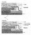
heat sink 602 that extends in a plane that is perpendicular to the view. Acircuit board 614 is disposed within the plane of theheat sink 602 such that an underside of the heat sink is in contact with thecircuit board 614. - A
flange 604 is situated on top of theheat sink 602. A transistor or integrated circuit die 608 is situated on theflange 604. Matching bond wires Li are provided on thedie 608. An output bond wire Ld couples thedie 608 to an output pin oroutput lead 610. A portion of theoutput lead 610 is within theovermold package 612 of the device. Another portion of theoutput lead 610 protrudes from the device and is couplable to thecircuit board 614. In the examples shown, thelead 610 is coupled to acontact 615 on thecircuit board 614 by solder. Aground plane 616 is provided on an opposite surface of thecircuit board 614 to thecontact 615. - In
figure 6a , the path of the forward current of the output signal is superimposed on to the structure of thedevice 600. The forward current originates at anoutput 609 of a transistor on thedie 608. The forward current is then conveyed by the outputbond wire Ld 611 to theoutput lead 610. Theoutput lead 610 provides the forward current to thecontact 615 on thecircuit board 614. - In
figure 6b , the path of the return current of the output signal is superimposed on to the structure of thedevice 600. The return current takes a different path to the forward current. The return current can be considered to originate at thecontact 615 between the lead 610 and thecircuit board 614. The return current passes through a matching circuit on thecircuit board 614 and along the bottom of thecircuit board 614. The return current is then conducted within a skin depth of theheatsink 602 and around theflange 604 back to thepoint 609 of the die 608 that is connected to the outputbond wires Ld 611. - The forward current path combined with the return current path forms a current loop. It has been found that it is these current loops that provide the electromagnetic fields that cause the crosstalk between the two amplifiers.
- It will be appreciated that crosstalk may also be experienced between the input leads of a single chip dual amplifier.
- Embodiments of the present invention provide a means to reduce the coupling between the amplifiers, as will be better appreciated by reference to the following description.
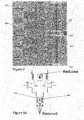
Figures 7a and 7b show schematics of twoamplifier devices 700a; 700b, which may be Doherty amplifier devices. The twoamplifier devices 700a; 700b comprise many common features. Each of theamplifier devices 700a; 700b comprise an integratedcircuit die 701a; 701b that has afirst amplifier 702a; 702b and asecond amplifier 704a; 704b. In Doherty amplifier implementations, thefirst amplifier 702a; 702b may be a main amplifier and thesecond amplifier 704a; 704b may be a peak amplifier.- The integrated
circuit die 701a; 701b is planar in this example and has afirst side 703a; 703b and asecond side 705a; 705b. Thefirst side 703a; 701b of the integratedcircuit die 701a; 701b opposes thesecond side 705a; 705b. - The
first amplifier 702a; 702b and thesecond amplifier 704a; 704b are provided on thefirst side 703a; 703b of the integratedcircuit die 701a; 701b. Thedevices first connector 706a; 706b, asecond connector 708a; 708b, a shieldingmember 710a; 710b and acapacitor 712a; 712b. - A
circuit board 718a; 718b is also illustrated in bothfigure 7a and figure 7b . Theamplifier device 700a; 700b is connected to thecircuit board 718a; 718b by thefirst connector 706a; 706b andsecond connector 708a; 708b. However, it will be appreciated that thecircuit board 718a; 718b is not an essential feature of the invention in some embodiments. - The
first connector 706a; 706b has afirst end 714a; 714b coupled to thefirst amplifier 702a; 702b and asecond end 716a; 716b for coupling with thecircuit board 718a; 718b. Thefirst connector 706a; 706b may be a first amplifier input or output pin. - The
second connector 708a; 708b has afirst end 720a; 720b coupled to thesecond amplifier 704a; 704b and asecond end 722a; 722b for coupling with thecircuit board 718a; 718b. Thesecond connector 708a; 708b may be a second amplifier input or output pin. - The shielding
member 710a; 710b has afirst end 724a; 724b coupled to the integrated circuit die and asecond end 726a; 726b for coupling with thecircuit board 718a; 718b. The shieldingmember 710a; 710b can comprise a bond wire that extends between thefirst end 724a; 724b and thesecond end 726a; 726b of the shieldingmember 710a; 710b. According to the claimed invention, the shieldingmember 710a; 710b comprises a bond wire in series with a ground connector/pin. The shieldingmember 710a; 710b is situated at least partially between thesecond connector 708a; 708b and thefirst connector 706a; 706b. Both ends of the shieldingmember 710a; 710b are coupled directly or indirectly to ground when the device is in use. The shielding member can be considered to form an electrical loop with ground in between thefirst connector 706a; 706b andsecond connector 708a; 708b. The loop may be considered as a ground-lead-bondwire-ground loop. This loop creates a current loop which acts as a magnetic shield that significantly reduces the coupling between the connectors of the first andsecond amplifiers 702a; 702b, 704a; 704b. That is, the shieldingmember 710a; 710b reduces the coupling between the loop inductances of the first andsecond amplifiers 702a; 702b, 704a; 704b. The shielding member also provides an alternative path for return current and reduces the return path inductance and coupling coefficient (k) between the first andsecond amplifiers 702a; 702b, 704a; 704b. The coupling coefficients between the forward paths of the first andsecond amplifiers 702a; 702b, 704a; 704b are also reduced, or shielded, by the shieldingmember 710a; 710b. - The shielding member current loop also reduces the value of the source inductance itself, which may also be beneficial to the RF performance of the
amplifier - The improvement in circuit properties derived from the shielding member will be described further with reference to
figures 10 to 12 . - The
first connector 706a; 706b,second connector 708a; 708b and shieldingmember 710a; 710b each extend in a common direction in the examples illustrated infigures 7a and 7b . - The
capacitor 712a; 712b, which has a first plate and a second plate, is also provided within the shielding member ground loop. However, the arrangement of the capacitor within the loop differs for theamplifier device 700a shown infigure 7a and theamplifier device 700b shown infigure 7b . As a general statement that covers both the devices shown infigure 7a and 7b , the first plate of thecapacitor 712a; 712b is configured to be coupled to ground when in use, the second plate of thecapacitor 712a; 712b is coupled to one of theends 724a; 726b of the shieldingmember 710a; 710b and theother end 726a; 724b of the shieldingmember 710a; 710b is configured to be coupled to ground when in use. - The
amplifier device 700a shown infigure 7a is an integrated amplifier, which can be an integrated Doherty amplifier and can be provided by a single package. The integratedcircuit die 701a comprises thecapacitor 712a. In this example, the first plate of thecapacitor 712a is provided on thesecond side 705a of the integratedcircuit die 701a that opposes thefirst side 703a. The first plate of thecapacitor 712a is configured to be coupled to ground when the device is in use. Any connections to ground that are required within theamplifier device 700a may be provided by a ground pin (not shown) on thedevice 700a that can connect to a ground plane of thecircuit board 718a, as is known in the art. Such a ground pin can be internally coupled to a ground plane of thedevice 700a. - The second plate of the
capacitor 712a is situated on thefirst side 703a of thedie 701a. The second plate of thecapacitor 712a is coupled to thefirst end 724a of the shieldingmember 710a. It will be appreciated that theintegrated capacitor 712a could be implemented in any other way. Thesecond end 726a of the shieldingmember 710a is configured to be coupled to ground at thecircuit board 718a. Infigure 7a , the ground coupling at thesecond end 726a of the shieldingmember 710a may be provided by a ground plane (not shown) of thecircuit board 718a. A via may can be provided through the circuit board between the shieldingmember 710a and the ground plane of thecircuit board 718a. - The
amplifier device 700b shown infigure 7b comprises an integrated amplifier which can be an integrated Doherty amplifier and comprises the components provided by the integratedcircuit die 701b. In this example, thecapacitor 712b is provided as a separate, discrete component from the integrated circuit die 701b and may be considered to be part of theamplifier device 700b, but not part of the integrated amplifier. The capacitor may be a variable capacitor in this example so as to allow tuning of the frequency response of the shield member ground loop. The first plate of thecapacitor 712b is configured to be coupled to ground when thedevice 700b is in use by, for example, coupling with a ground plane or ground track of thecircuit board 718b. The second plate of thecapacitor 712b is coupled to thesecond end 726b of the shieldingmember 710b. Thefirst end 724b of the shieldingmember 710b is coupled to ground when in use by, for example, a contact on the surface of the integrated circuit die 701b and a via through the integratedcircuit die 701b. The via couples thefirst end 724b of the shieldingmember 710b with a ground plane of thedie 701b. The contact can be located on top of the integratedcircuit die 701b. In some examples, a low ohmic substrate is provided so that the whole of the substrate of the integrated circuit die 701b acts as a via. In the case where the integratedcircuit die 701b has a high ohmic substrate, a real via through the die may be provided. - In other examples, not falling under the claimed invention, the "active"
die - In implementations where more than two amplifiers are provided within a package, a shielding member may be provided between the connections of each amplifier. The additional shielding members may have similar electrical properties to the shielding member discussed with reference to
figures 7a and 7b in order to reduce the crosstalk between each of the amplifiers. - It will be appreciated that two capacitors may be provided in series in the shielding member ground loop in some examples. A first capacitor may be provided on the die and a second capacitor may be provided on (or configured to be connected to) a circuit board. A first plate of both of the first and second capacitors is configured to be coupled to ground. Second plates of the respective first and second capacitors are coupled to one another through the shielding member. The first capacitor may have a fixed value and be used to provide a coarse level of impedance control. The second capacitor may be a variable capacitor and so be used to fine-tune the impedance response of the shielding member. Implementations of this example may reduce the capacitance requirement of the variable capacitor and so allow for more precise control of the impendence. Additionally, the reduced capacitance requirement of the variable capacitor may allow for the use of a less expensive variable capacitor. However, when two capacitors are provided in series a higher capacitance may be required outside the package to achieve the same effective value.
- The term "electrically coupled" or "coupled" may mean that a component has a direct or indirect electrical connection with another component to allow electrical conduction. A "coupling" may allow a significant electronic current flow between the features that it couples. The term "coupled" is reserved for such electrical coupling herein. "Capacitive coupling" or "inductive coupling" may be referred to herein as "electromagnetic coupling", meaning "electromagnetic field coupling". A "connection" may refer to an electrical connection or to a physical connection between two components.
Figure 8 also shows a schematic of a device 800 based on the device illustrated infigure 4 . The device 800 offigure 8 comprises a shieldingmember 810 and acapacitor 812 in addition to the components of the device offigure 4 . The arrangement of the shieldingmember 810 and thecapacitor 812 is similar to that illustrated infigure 7b .- A shielding path can be considered to start at a ground plane of a
die 801. The ground plane of thedie 801 is coupled to the shieldingmember 810 at a first end 824 of the shieldingmember 810. The shieldingmember 810 comprises a bond wire at its first end 824 and a pin, or lead, at itssecond end 826. The bond wire and the pin are in series with each other. Thesecond end 826 of the shieldingmember 810 is coupled to a second plate of thecapacitor 812. The first plate of thecapacitor 812 is coupled to a ground plane of acircuit board 818. Alternatively, the second plate of thecapacitor 812 may be provided on a surface of thecircuit board 818 that opposes a surface on which the ground plane is provided. The first plate of thecapacitor 812 may be comprised by the ground plane of thecircuit board 818 in such an example. The ground plane of thecircuit board 818 and the ground plane of thedie 801 can be in direct electrical contact with one another, for example, they may be connected by a ground pin of an integrated circuit package that houses thedie 801. Figure 9a shows an equivalent circuit diagram for the amplifier device offigures 7 and8 . The coupling coefficient (k') between the output bond wires/leads 910 of thefirst amplifier 902 and theleads 912 of thesecond amplifier 904 is reduced by the provision of the shielding member. Thefirst source inductance 906 of thefirst amplifier 902 and thesecond source inductance 908 of thesecond amplifier 904 are also reduced by the shielding member, as is the coupling coefficient (k) between thefirst source inductance 906 andsecond source inductance 908. The effect of the shielding member is indicated infigure 9 , although the shielding member itself is not shown. The shielding member is provided betweenleads 910 of thefirst amplifier 902 and theleads 912 of thesecond amplifier 904.Figure 9b illustrates in an example not falling within the scope of the claimed invention a multi-unit LC circuit 900 that provides a shieldingmember 910 andmultiple capacitors 934. The shieldingmember 910 provides an inductance, which can be considered to be a number ofinductors 932 coupled in series. The shieldingmember 910 has afirst end 924 and asecond end 926. Thefirst end 924 of the shieldingmember 910 may be coupled to a ground plane of a die. Thesecond end 926 of the shieldingmember 910 may be coupled to a ground plane of a circuit board. In the example shown infigure 9b , thesecond end 926 of the shieldingmember 910 is coupled to ground via acapacitor 938.Multiple LC units 930 are provided between thefirst end 924 of the shieldingmember 910 and ground at thesecond end 926 of the shieldingmember 910. EachLC unit 930 comprises aninductor 932 of the shieldingmember 910 and acapacitor 934. Theinductor 932 has a first terminal and a second terminal and thecapacitor 934 has a first plate and a second plate. The first plate of eachcapacitor 934 is coupled to the second end of theinductor 932. The second plate of eachcapacitor 934 is coupled toground 936.- The first end of the
inductor 932 of the first of theLC units 930 is coupled to thefirst end 924 of the shieldingmember 910.LC units 930 are added incrementally to the first LC unit, from left to right in the example offigure 9b . The first terminal of theinductor 932 of asubsequent LC unit 930 is connected to the second terminal of the inductor of a previous LC unit. The second terminal of the inductor of the last of the LC unit can be considered to be thesecond end 926 of the shieldingmember 910. - The effect of providing
multiple capacitors 934 spaced apart along the shieldingmember 910 is that the impedance of the shieldingmember 910 may be reduced. It will be appreciated that parts of the shieldingmember 910 and thecapacitors 934 may be provided on an integrated circuit, on a circuit board or between the integrated circuit and circuit board. The shieldingmember 910 andcapacitors 934 can be considered as a shielding fence, where thecapacitors 934 provide vertical fence elements and theinductors 932 of the shieldingmember 910 provide horizontal fence elements. - Another effect of the provision of
multiple capacitors 934 along the shieldingmember 910 is that the cross talk and the loop impedance of a device incorporating the shieldingmember 934 become more suited to broadband applications, as will be discussed further with respect tofigures 13 and 14 below. Figure 10a shows return current density values superimposed on a portion of the schematic offigure 8 .Figure 10b shows return current density values superimposed on a perspective view of the schematic offigure 8 .- The simulation results illustrated in
figure 10 show that the shieldingmember 1002 carries most of the return current. The shieldingmember 1002 therefore not only acts as a magnetic shield between the current loops of the twoamplifiers - In the simulation shown, only the
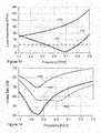
first amplifier 1004 is active. The current density of the shieldingmember 1002 is therefore highest on the side of the activefirst amplifier 1004; the shieldingmember 1002 acts as a mirror to the current from a loop of thefirst amplifier 1004. The shielding member may be configured to carry a significant amount of return current. Figure 11 shows a plot of loop impedance against frequency for two different amplifier devices that have shielding members as disclosed herein. Afirst plot 1102 illustrates the impedance response of an amplifier with a shielding member without a capacitor. Asecond plot 1104 illustrates the impedance response of an amplifier having a shielding member with a capacitor situated off the die of the amplifier, such as the examples shown infigure 7b or8 .- The
first plot 1102 has an impedance of 50 ohms at 1.7 GHz, which increases to around 135 ohms at 2.3 GHz. The gradient of thefirst plot 1102 also increases with frequency. - The
second plot 1104 has an impedance of around 55 ohms at 1.7 GHz. Thesecond plot 1104 impedance decreases in an approximately linear manner to around 5 ohms at around 2.09 GHz (highlighted circle 1106). At frequencies above 2.09 GHz the impedance and gradient of thesecond plot 1104 increases with frequency. Thesecond plot 1104 impedance is around 60 ohms at 2.3 GHz. - It can be seen from
figure 11 that the provision of a capacitor coupled to the shielding member reduces the total impedance of the ground loop for a wide range of frequencies. Also the frequency response of the impedance may be tuned by altering the value of the capacitor. A variable capacitor can be provided to allow for such control of the shielding loop impedance. For this reason it is preferable, although not essential, that the capacitor is provided on the circuit board side since, in this way, the capacitor can be tuned to further reduce crosstalk. Figure 12 shows a plot of crosstalk against frequency simulations for the amplifier implemented in the device offigure 4 and two amplifier devices that comprise shielding members.- A
first plot 1202 shows the performance of the performance of the amplifier offigure 4 (no shielding member), and is similar to the plot infigure 3 . Asecond plot 1204 shows the performance of the performance of an amplifier with a shielding member without a capacitor. Athird plot 1206 shows the performance of an amplifier with a shielding member and an external capacitor. - All of the
plots plots - At the minima, the crosstalk of the
first plot 1202 is -30 dB, the crosstalk of thesecond plot 1204 is around -37 dB and the crosstalk of thethird plot 1206 is around -58 dB. At 2.1 GHz, which may be an operating frequency for a Doherty amplifier in some base station applications, the crosstalk of thefirst plot 1202 is around -5 dB, the crosstalk of thesecond plot 1204 is around -13 dB and the crosstalk of thethird plot 1206 is around - 32 dB. That is, the third plot provides a crosstalk below the required threshold of -25 dB. It will be appreciated forfigures 11 and 12 that the provision of a capacitor results in significant improvement in device performance, both in terms of reduced crosstalk and loop impedance at a desired operating frequency. Figure 13 shows a plot of loop impedance against frequency for three different amplifier devices that have shielding members as disclosed herein. Afirst plot 1302 and asecond plot 1304 infigure 13 are similar to those shown infigure 11 . Athird plot 1308 shows the impedance response of an amplifier with a shielding member and capacitor as described with reference tofigure 9b . The arrangement offigure 9b produces a low loop impedance over a broad frequency range. In this example, not falling under the claimed invention, the loop impedance is less than 30 Ω between 1.7 and 2.3 GHz.Figure 14 shows a plot of crosstalk against frequency simulations for the amplifier implemented in the device offigure 4 and two amplifier devices that comprise shielding members.- A
first plot 1402 shows the performance of the performance of the amplifier offigure 4 (no shielding member), and is similar to the plot infigures 3 and12 . - A
second plot 1405 shows the performance of an amplifier with a shielding member and multiple capacitors as illustrated infigure 9b . Thesecond plot 1405 has two minima, at 1.85 GHz and 2.02 GHz. The cross talk levels at the minima are around -44 dB. Such an amplifier provides a broad frequency range (around 1.72 GHz to 2.3 GHz illustrated infigure 14 ) over which the cross talk is below the required threshold level of -25 dB. - A
third plot 1406 shows the performance of an amplifier with a shielding member and an external capacitor, and is similar to the corresponding plot infigure 12 .
Claims (5)
- An amplifier device (700a) configured to be connected to a circuit board (718a) that has a ground plane, the amplifier device (700a) comprising:an integrated circuit die (701a) having a first amplifier (702a) and a second amplifier (704a), the integrated circuit die (701a) having a first side (703a) and a second side (705a) opposing the first side (703a), wherein the first amplifier (702a) and the second amplifier (704a) are provided on the first side (703a) of the integrated circuit die (701a);a first connector (706a) having a first end (714a) coupled to the first amplifier (702a) and a second end lead (716a) for coupling with the circuit board (718a);a second connector (708a) having a first end (720a) coupled to the second amplifier (704a) and a second end lead (722a) for coupling with the circuit board (718a);a shielding member (710a) comprising a bond wire in series with a ground connector pin, the shielding member having a first bond wire end (724a) and a second ground connector pin end (726a), wherein the first bond wire end (724a) is coupled to the integrated circuit die (701a), and wherein the second ground connector pin end (726a) is configured for electrically coupling with the ground plane of the circuit board (718a), wherein the shielding member (710a) is situated at least partially between the second connector (708a) and the first connector (706a); anda capacitor (712a) integrated on the integrated circuit die (701a) and provided with a grounded first plate and a second plate, wherein the second plate of the capacitor (712a) is arranged on the first side (703a) of the integrated circuit die (701a) and coupled to the first bond wire end (724a) of the shielding member.
- The amplifier device (700a) of claim 1, wherein the amplifier device (700a) is a Doherty amplifier device, the first amplifier (702a) being a main amplifier and the second amplifier (704a) being a peak amplifier.
- An apparatus, comprising:a circuit board (718a) having a ground plane; andthe amplifier device (700a) of any preceding claim connected to the circuit board (718a), wherein the second end leads (716a, 722a) of the first connector (706a) and second connector (708a) are connected to the circuit board (718a), and wherein the second ground connector pin end (726a) is electrically coupled to the ground plane of the circuit board (718a).
- An apparatus, comprising:a circuit board (718b) comprising a ground plane;a capacitor (712b), the capacitor (712b) having a first plate and a second plate, wherein the first plate is electrically connected to the ground plane of the circuit board (718b); andan amplifier device (700b) connected to the circuit board (718b), and comprising:an integrated circuit die (701b) having a first amplifier (702b) and a second amplifier (704b), the integrated circuit die (701b) having a first side (703b) and a second side (705b) opposing the first side (703b), wherein the first amplifier (702b) and the second amplifier (704b) are provided on the first side (703b) of the integrated circuit die (701b);a first connector (706b) having a first end (714b) coupled to the first amplifier (702b) and a second end lead (716b) coupled with the circuit board (718b);a second connector (708b) having a first end (720b) coupled to the second amplifier (704b) and a second end lead (722b) coupled with the circuit board (718b); anda shielding member (710b) comprising a bond wire in series with a ground connector pin, the shielding member having a first bond wire end (724b) and a second ground connector pin end (726b), wherein the first bond wire end (724b) of the shielding member (710b) is coupled to ground of the integrated circuit die (701b) and wherein the second ground connector pin end (726b) is electrically coupled with the second plate of the capacitor (712b), wherein the shielding member (710b) is situated at least partially between the second connector (708b) and the first connector (706b).
- The apparatus of claim 4, wherein the amplifier device (700b) is a Doherty amplifier device, the first amplifier (702b) being a main amplifier and the second amplifier (704b) being a peak amplifier.
Priority Applications (2)
| Application Number | Priority Date | Filing Date | Title |
|---|---|---|---|
| EP12197882.9AEP2747134B1 (en) | 2012-12-18 | 2012-12-18 | Amplifier device |
| US14/109,879US9007129B2 (en) | 2012-12-18 | 2013-12-17 | Amplifer device |
Applications Claiming Priority (1)
| Application Number | Priority Date | Filing Date | Title |
|---|---|---|---|
| EP12197882.9AEP2747134B1 (en) | 2012-12-18 | 2012-12-18 | Amplifier device |
Publications (2)
| Publication Number | Publication Date |
|---|---|
| EP2747134A1 EP2747134A1 (en) | 2014-06-25 |
| EP2747134B1true EP2747134B1 (en) | 2021-09-01 |
Family
ID=47520754
Family Applications (1)
| Application Number | Title | Priority Date | Filing Date |
|---|---|---|---|
| EP12197882.9AActiveEP2747134B1 (en) | 2012-12-18 | 2012-12-18 | Amplifier device |
Country Status (2)
| Country | Link |
|---|---|
| US (1) | US9007129B2 (en) |
| EP (1) | EP2747134B1 (en) |
Families Citing this family (16)
| Publication number | Priority date | Publication date | Assignee | Title |
|---|---|---|---|---|
| US9312817B2 (en) | 2012-07-20 | 2016-04-12 | Freescale Semiconductor, Inc. | Semiconductor package design providing reduced electromagnetic coupling between circuit components |
| US9401342B2 (en)* | 2013-06-27 | 2016-07-26 | Freescale Semiconductor, Inc. | Semiconductor package having wire bond wall to reduce coupling |
| WO2014207498A1 (en)* | 2013-06-27 | 2014-12-31 | Freescale Semiconductor, Inc. | High frequency amplifier |
| US9240390B2 (en) | 2013-06-27 | 2016-01-19 | Freescale Semiconductor, Inc. | Semiconductor packages having wire bond wall to reduce coupling |
| US9450547B2 (en) | 2013-12-12 | 2016-09-20 | Freescale Semiconductor, Inc. | Semiconductor package having an isolation wall to reduce electromagnetic coupling |
| US9673164B2 (en) | 2014-04-25 | 2017-06-06 | Nxp Usa, Inc. | Semiconductor package and system with an isolation structure to reduce electromagnetic coupling |
| EP2950342B1 (en) | 2014-05-30 | 2020-10-21 | Ampleon Netherlands B.V. | Integrated circuit arrangement |
| US9893025B2 (en)* | 2014-10-01 | 2018-02-13 | Analog Devices Global | High isolation wideband switch |
| US9986646B2 (en) | 2014-11-21 | 2018-05-29 | Nxp Usa, Inc. | Packaged electronic devices with top terminations, and methods of manufacture thereof |
| EP3093990B1 (en)* | 2015-05-13 | 2018-08-15 | Ampleon Netherlands B.V. | Guard bond wires in an integrated circuit package |
| DE102015212247A1 (en) | 2015-06-30 | 2017-01-05 | TRUMPF Hüttinger GmbH + Co. KG | RF amplifier arrangement |
| DE102015212152B4 (en) | 2015-06-30 | 2018-03-15 | TRUMPF Hüttinger GmbH + Co. KG | Non-linear radio frequency amplifier arrangement |
| WO2017019738A1 (en)* | 2015-07-30 | 2017-02-02 | Laird Technologies, Inc. | Soft and/or flexible emi shields and related methods |
| US9607953B1 (en) | 2016-02-24 | 2017-03-28 | Nxp Usa, Inc. | Semiconductor package with isolation wall |
| JP7306289B2 (en)* | 2020-02-10 | 2023-07-11 | 住友電気工業株式会社 | semiconductor devices and amplifiers |
| US11581859B2 (en)* | 2020-06-26 | 2023-02-14 | Wolfspeed, Inc. | Radio frequency (RF) transistor amplifier packages with improved isolation and lead configurations |
Family Cites Families (13)
| Publication number | Priority date | Publication date | Assignee | Title |
|---|---|---|---|---|
| JPH0754887B2 (en)* | 1984-11-16 | 1995-06-07 | 株式会社日立製作所 | Microwave solid state amplifier |
| US4614878A (en)* | 1985-02-11 | 1986-09-30 | Motorola, Inc. | Pulse generator |
| JP2755250B2 (en)* | 1996-03-22 | 1998-05-20 | 日本電気株式会社 | Semiconductor integrated circuit |
| US5973568A (en)* | 1998-06-01 | 1999-10-26 | Motorola Inc. | Power amplifier output module for dual-mode digital systems |
| US7525813B2 (en)* | 1998-07-06 | 2009-04-28 | Renesas Technology Corp. | Semiconductor device |
| US6300827B1 (en) | 1999-12-09 | 2001-10-09 | Maxim Integrated Products, Inc. | Method and apparatus for cascaded ground return amplifier |
| TW200518345A (en)* | 2003-08-08 | 2005-06-01 | Renesas Tech Corp | Semiconductor device |
| DE102004031687B4 (en)* | 2004-06-30 | 2013-01-31 | Infineon Technologies Ag | Power amplifier arrangement |
| WO2007003224A1 (en)* | 2005-07-05 | 2007-01-11 | Freescale Semiconductor, Inc. | Compensation for parasitic coupling between rf or microwave transistors in the same package |
| US7683480B2 (en) | 2006-03-29 | 2010-03-23 | Freescale Semiconductor, Inc. | Methods and apparatus for a reduced inductance wirebond array |
| US8030763B2 (en)* | 2008-06-26 | 2011-10-04 | Freescale Semiconductor, Inc. | Semiconductor package with reduced inductive coupling between adjacent bondwire arrays |
| JP5483581B2 (en)* | 2010-07-20 | 2014-05-07 | 住友電工デバイス・イノベーション株式会社 | Doherty amplifier and semiconductor device |
| KR101141381B1 (en) | 2010-08-16 | 2012-07-13 | 삼성전기주식회사 | Communication circuit for reducing crosstalk |
- 2012
- 2012-12-18EPEP12197882.9Apatent/EP2747134B1/enactiveActive
- 2013
- 2013-12-17USUS14/109,879patent/US9007129B2/enactiveActive
Also Published As
| Publication number | Publication date |
|---|---|
| US9007129B2 (en) | 2015-04-14 |
| EP2747134A1 (en) | 2014-06-25 |
| US20140167858A1 (en) | 2014-06-19 |
Similar Documents
| Publication | Publication Date | Title |
|---|---|---|
| EP2747134B1 (en) | Amplifier device | |
| EP3337037B1 (en) | Doherty amplifiers and amplifier modules with shunt inductance circuits that affect transmission line length between carrier and peaking amplifier outputs | |
| US10269729B2 (en) | Semiconductor packages having wire bond wall to reduce coupling | |
| US9748185B2 (en) | Semiconductor devices with impedance matching-circuits | |
| US9820401B2 (en) | Packaged RF power transistor device having next to each other a ground and a video lead for connecting a decoupling capacitor, RF power amplifier | |
| US6633005B2 (en) | Multilayer RF amplifier module | |
| US10381984B2 (en) | Amplifiers and amplifier modules with shunt inductance circuits that include high-Q capacitors | |
| EP3160043B1 (en) | Output impedance matching circuit for rf amplifier devices, and methods of manufacture thereof | |
| US9711486B2 (en) | Stacked semiconductor device | |
| US9629246B2 (en) | PCB based semiconductor package having integrated electrical functionality | |
| CN108206677B (en) | Multi-baseband termination assembly for RF power amplifier with enhanced video bandwidth | |
| CN110504922A (en) | Broadband power transistor device and amplifier and method of manufacture | |
| US11349438B2 (en) | Power amplifier packages containing multi-path integrated passive devices | |
| EP3852270A1 (en) | Rf amplifiers with series-coupled output bondwire arrays and shunt capacitor bondwire array | |
| US20150294930A1 (en) | RF Power Transistor | |
| US11296662B2 (en) | High-frequency power amplifier | |
| CN110829988A (en) | Amplifier with broadband impedance matching and method of manufacturing the same | |
| CN111726088A (en) | Amplifying circuit | |
| US9252767B1 (en) | Integrated switch module | |
| US9991854B1 (en) | Power amplifier output circuit arrangements with mutual coupling between inductors | |
| US10553543B2 (en) | Guard bond wires in an integrated circuit package | |
| KR20140001102A (en) | Reduced size bias tee | |
| CN114759888A (en) | RF amplifier with series coupled output bond wire array and parallel capacitor bond wire array | |
| CN116781021A (en) | RF power amplifier | |
| JP2022512148A (en) | High frequency power transistor and high frequency power amplifier |
Legal Events
| Date | Code | Title | Description |
|---|---|---|---|
| PUAI | Public reference made under article 153(3) epc to a published international application that has entered the european phase | Free format text:ORIGINAL CODE: 0009012 | |
| 17P | Request for examination filed | Effective date:20131031 | |
| AK | Designated contracting states | Kind code of ref document:A1 Designated state(s):AL AT BE BG CH CY CZ DE DK EE ES FI FR GB GR HR HU IE IS IT LI LT LU LV MC MK MT NL NO PL PT RO RS SE SI SK SM TR | |
| AX | Request for extension of the european patent | Extension state:BA ME | |
| RBV | Designated contracting states (corrected) | Designated state(s):AL AT BE BG CH CY CZ DE DK EE ES FI FR GB GR HR HU IE IS IT LI LT LU LV MC MK MT NL NO PL PT RO RS SE SI SK SM TR | |
| RAP1 | Party data changed (applicant data changed or rights of an application transferred) | Owner name:SAMBA HOLDCO NETHERLANDS B.V. | |
| RAP1 | Party data changed (applicant data changed or rights of an application transferred) | Owner name:AMPLEON NETHERLANDS B.V. | |
| STAA | Information on the status of an ep patent application or granted ep patent | Free format text:STATUS: EXAMINATION IS IN PROGRESS | |
| 17Q | First examination report despatched | Effective date:20190412 | |
| GRAP | Despatch of communication of intention to grant a patent | Free format text:ORIGINAL CODE: EPIDOSNIGR1 | |
| STAA | Information on the status of an ep patent application or granted ep patent | Free format text:STATUS: GRANT OF PATENT IS INTENDED | |
| INTG | Intention to grant announced | Effective date:20210510 | |
| GRAS | Grant fee paid | Free format text:ORIGINAL CODE: EPIDOSNIGR3 | |
| GRAA | (expected) grant | Free format text:ORIGINAL CODE: 0009210 | |
| STAA | Information on the status of an ep patent application or granted ep patent | Free format text:STATUS: THE PATENT HAS BEEN GRANTED | |
| AK | Designated contracting states | Kind code of ref document:B1 Designated state(s):AL AT BE BG CH CY CZ DE DK EE ES FI FR GB GR HR HU IE IS IT LI LT LU LV MC MK MT NL NO PL PT RO RS SE SI SK SM TR | |
| REG | Reference to a national code | Ref country code:GB Ref legal event code:FG4D | |
| REG | Reference to a national code | Ref country code:CH Ref legal event code:EP Ref country code:AT Ref legal event code:REF Ref document number:1427118 Country of ref document:AT Kind code of ref document:T Effective date:20210915 | |
| REG | Reference to a national code | Ref country code:DE Ref legal event code:R096 Ref document number:602012076584 Country of ref document:DE | |
| REG | Reference to a national code | Ref country code:IE Ref legal event code:FG4D | |
| REG | Reference to a national code | Ref country code:NL Ref legal event code:FP | |
| REG | Reference to a national code | Ref country code:LT Ref legal event code:MG9D | |
| PG25 | Lapsed in a contracting state [announced via postgrant information from national office to epo] | Ref country code:NO Free format text:LAPSE BECAUSE OF FAILURE TO SUBMIT A TRANSLATION OF THE DESCRIPTION OR TO PAY THE FEE WITHIN THE PRESCRIBED TIME-LIMIT Effective date:20211201 Ref country code:RS Free format text:LAPSE BECAUSE OF FAILURE TO SUBMIT A TRANSLATION OF THE DESCRIPTION OR TO PAY THE FEE WITHIN THE PRESCRIBED TIME-LIMIT Effective date:20210901 Ref country code:ES Free format text:LAPSE BECAUSE OF FAILURE TO SUBMIT A TRANSLATION OF THE DESCRIPTION OR TO PAY THE FEE WITHIN THE PRESCRIBED TIME-LIMIT Effective date:20210901 Ref country code:FI Free format text:LAPSE BECAUSE OF FAILURE TO SUBMIT A TRANSLATION OF THE DESCRIPTION OR TO PAY THE FEE WITHIN THE PRESCRIBED TIME-LIMIT Effective date:20210901 Ref country code:BG Free format text:LAPSE BECAUSE OF FAILURE TO SUBMIT A TRANSLATION OF THE DESCRIPTION OR TO PAY THE FEE WITHIN THE PRESCRIBED TIME-LIMIT Effective date:20211201 Ref country code:LT Free format text:LAPSE BECAUSE OF FAILURE TO SUBMIT A TRANSLATION OF THE DESCRIPTION OR TO PAY THE FEE WITHIN THE PRESCRIBED TIME-LIMIT Effective date:20210901 Ref country code:HR Free format text:LAPSE BECAUSE OF FAILURE TO SUBMIT A TRANSLATION OF THE DESCRIPTION OR TO PAY THE FEE WITHIN THE PRESCRIBED TIME-LIMIT Effective date:20210901 Ref country code:SE Free format text:LAPSE BECAUSE OF FAILURE TO SUBMIT A TRANSLATION OF THE DESCRIPTION OR TO PAY THE FEE WITHIN THE PRESCRIBED TIME-LIMIT Effective date:20210901 | |
| REG | Reference to a national code | Ref country code:AT Ref legal event code:MK05 Ref document number:1427118 Country of ref document:AT Kind code of ref document:T Effective date:20210901 | |
| PG25 | Lapsed in a contracting state [announced via postgrant information from national office to epo] | Ref country code:PL Free format text:LAPSE BECAUSE OF FAILURE TO SUBMIT A TRANSLATION OF THE DESCRIPTION OR TO PAY THE FEE WITHIN THE PRESCRIBED TIME-LIMIT Effective date:20210901 Ref country code:LV Free format text:LAPSE BECAUSE OF FAILURE TO SUBMIT A TRANSLATION OF THE DESCRIPTION OR TO PAY THE FEE WITHIN THE PRESCRIBED TIME-LIMIT Effective date:20210901 Ref country code:GR Free format text:LAPSE BECAUSE OF FAILURE TO SUBMIT A TRANSLATION OF THE DESCRIPTION OR TO PAY THE FEE WITHIN THE PRESCRIBED TIME-LIMIT Effective date:20211202 | |
| PG25 | Lapsed in a contracting state [announced via postgrant information from national office to epo] | Ref country code:AT Free format text:LAPSE BECAUSE OF FAILURE TO SUBMIT A TRANSLATION OF THE DESCRIPTION OR TO PAY THE FEE WITHIN THE PRESCRIBED TIME-LIMIT Effective date:20210901 | |
| PG25 | Lapsed in a contracting state [announced via postgrant information from national office to epo] | Ref country code:IS Free format text:LAPSE BECAUSE OF FAILURE TO SUBMIT A TRANSLATION OF THE DESCRIPTION OR TO PAY THE FEE WITHIN THE PRESCRIBED TIME-LIMIT Effective date:20220101 Ref country code:SM Free format text:LAPSE BECAUSE OF FAILURE TO SUBMIT A TRANSLATION OF THE DESCRIPTION OR TO PAY THE FEE WITHIN THE PRESCRIBED TIME-LIMIT Effective date:20210901 Ref country code:SK Free format text:LAPSE BECAUSE OF FAILURE TO SUBMIT A TRANSLATION OF THE DESCRIPTION OR TO PAY THE FEE WITHIN THE PRESCRIBED TIME-LIMIT Effective date:20210901 Ref country code:RO Free format text:LAPSE BECAUSE OF FAILURE TO SUBMIT A TRANSLATION OF THE DESCRIPTION OR TO PAY THE FEE WITHIN THE PRESCRIBED TIME-LIMIT Effective date:20210901 Ref country code:PT Free format text:LAPSE BECAUSE OF FAILURE TO SUBMIT A TRANSLATION OF THE DESCRIPTION OR TO PAY THE FEE WITHIN THE PRESCRIBED TIME-LIMIT Effective date:20220103 Ref country code:EE Free format text:LAPSE BECAUSE OF FAILURE TO SUBMIT A TRANSLATION OF THE DESCRIPTION OR TO PAY THE FEE WITHIN THE PRESCRIBED TIME-LIMIT Effective date:20210901 Ref country code:CZ Free format text:LAPSE BECAUSE OF FAILURE TO SUBMIT A TRANSLATION OF THE DESCRIPTION OR TO PAY THE FEE WITHIN THE PRESCRIBED TIME-LIMIT Effective date:20210901 Ref country code:AL Free format text:LAPSE BECAUSE OF FAILURE TO SUBMIT A TRANSLATION OF THE DESCRIPTION OR TO PAY THE FEE WITHIN THE PRESCRIBED TIME-LIMIT Effective date:20210901 | |
| REG | Reference to a national code | Ref country code:DE Ref legal event code:R097 Ref document number:602012076584 Country of ref document:DE | |
| PLBE | No opposition filed within time limit | Free format text:ORIGINAL CODE: 0009261 | |
| STAA | Information on the status of an ep patent application or granted ep patent | Free format text:STATUS: NO OPPOSITION FILED WITHIN TIME LIMIT | |
| PG25 | Lapsed in a contracting state [announced via postgrant information from national office to epo] | Ref country code:MC Free format text:LAPSE BECAUSE OF FAILURE TO SUBMIT A TRANSLATION OF THE DESCRIPTION OR TO PAY THE FEE WITHIN THE PRESCRIBED TIME-LIMIT Effective date:20210901 Ref country code:IT Free format text:LAPSE BECAUSE OF FAILURE TO SUBMIT A TRANSLATION OF THE DESCRIPTION OR TO PAY THE FEE WITHIN THE PRESCRIBED TIME-LIMIT Effective date:20210901 Ref country code:DK Free format text:LAPSE BECAUSE OF FAILURE TO SUBMIT A TRANSLATION OF THE DESCRIPTION OR TO PAY THE FEE WITHIN THE PRESCRIBED TIME-LIMIT Effective date:20210901 | |
| REG | Reference to a national code | Ref country code:CH Ref legal event code:PL | |
| 26N | No opposition filed | Effective date:20220602 | |
| PG25 | Lapsed in a contracting state [announced via postgrant information from national office to epo] | Ref country code:SI Free format text:LAPSE BECAUSE OF FAILURE TO SUBMIT A TRANSLATION OF THE DESCRIPTION OR TO PAY THE FEE WITHIN THE PRESCRIBED TIME-LIMIT Effective date:20210901 | |
| REG | Reference to a national code | Ref country code:BE Ref legal event code:MM Effective date:20211231 | |
| PG25 | Lapsed in a contracting state [announced via postgrant information from national office to epo] | Ref country code:LU Free format text:LAPSE BECAUSE OF NON-PAYMENT OF DUE FEES Effective date:20211218 | |
| PG25 | Lapsed in a contracting state [announced via postgrant information from national office to epo] | Ref country code:BE Free format text:LAPSE BECAUSE OF NON-PAYMENT OF DUE FEES Effective date:20211231 | |
| PG25 | Lapsed in a contracting state [announced via postgrant information from national office to epo] | Ref country code:LI Free format text:LAPSE BECAUSE OF NON-PAYMENT OF DUE FEES Effective date:20211231 Ref country code:CH Free format text:LAPSE BECAUSE OF NON-PAYMENT OF DUE FEES Effective date:20211231 | |
| PGFP | Annual fee paid to national office [announced via postgrant information from national office to epo] | Ref country code:NL Payment date:20221226 Year of fee payment:11 Ref country code:IE Payment date:20221227 Year of fee payment:11 Ref country code:GB Payment date:20221227 Year of fee payment:11 Ref country code:FR Payment date:20221227 Year of fee payment:11 | |
| PG25 | Lapsed in a contracting state [announced via postgrant information from national office to epo] | Ref country code:HU Free format text:LAPSE BECAUSE OF FAILURE TO SUBMIT A TRANSLATION OF THE DESCRIPTION OR TO PAY THE FEE WITHIN THE PRESCRIBED TIME-LIMIT; INVALID AB INITIO Effective date:20121218 Ref country code:CY Free format text:LAPSE BECAUSE OF FAILURE TO SUBMIT A TRANSLATION OF THE DESCRIPTION OR TO PAY THE FEE WITHIN THE PRESCRIBED TIME-LIMIT Effective date:20210901 | |
| P01 | Opt-out of the competence of the unified patent court (upc) registered | Effective date:20230526 | |
| PG25 | Lapsed in a contracting state [announced via postgrant information from national office to epo] | Ref country code:MK Free format text:LAPSE BECAUSE OF FAILURE TO SUBMIT A TRANSLATION OF THE DESCRIPTION OR TO PAY THE FEE WITHIN THE PRESCRIBED TIME-LIMIT Effective date:20210901 | |
| PG25 | Lapsed in a contracting state [announced via postgrant information from national office to epo] | Ref country code:TR Free format text:LAPSE BECAUSE OF FAILURE TO SUBMIT A TRANSLATION OF THE DESCRIPTION OR TO PAY THE FEE WITHIN THE PRESCRIBED TIME-LIMIT Effective date:20210901 | |
| REG | Reference to a national code | Ref country code:NL Ref legal event code:MM Effective date:20240101 | |
| GBPC | Gb: european patent ceased through non-payment of renewal fee | Effective date:20231218 | |
| PG25 | Lapsed in a contracting state [announced via postgrant information from national office to epo] | Ref country code:NL Free format text:LAPSE BECAUSE OF NON-PAYMENT OF DUE FEES Effective date:20240101 | |
| PG25 | Lapsed in a contracting state [announced via postgrant information from national office to epo] | Ref country code:NL Free format text:LAPSE BECAUSE OF NON-PAYMENT OF DUE FEES Effective date:20240101 Ref country code:MT Free format text:LAPSE BECAUSE OF FAILURE TO SUBMIT A TRANSLATION OF THE DESCRIPTION OR TO PAY THE FEE WITHIN THE PRESCRIBED TIME-LIMIT Effective date:20210901 | |
| REG | Reference to a national code | Ref country code:IE Ref legal event code:MM4A | |
| PG25 | Lapsed in a contracting state [announced via postgrant information from national office to epo] | Ref country code:IE Free format text:LAPSE BECAUSE OF NON-PAYMENT OF DUE FEES Effective date:20231218 | |
| PG25 | Lapsed in a contracting state [announced via postgrant information from national office to epo] | Ref country code:GB Free format text:LAPSE BECAUSE OF NON-PAYMENT OF DUE FEES Effective date:20231218 | |
| PG25 | Lapsed in a contracting state [announced via postgrant information from national office to epo] | Ref country code:FR Free format text:LAPSE BECAUSE OF NON-PAYMENT OF DUE FEES Effective date:20231231 | |
| PG25 | Lapsed in a contracting state [announced via postgrant information from national office to epo] | Ref country code:IE Free format text:LAPSE BECAUSE OF NON-PAYMENT OF DUE FEES Effective date:20231218 Ref country code:GB Free format text:LAPSE BECAUSE OF NON-PAYMENT OF DUE FEES Effective date:20231218 Ref country code:FR Free format text:LAPSE BECAUSE OF NON-PAYMENT OF DUE FEES Effective date:20231231 | |
| PGFP | Annual fee paid to national office [announced via postgrant information from national office to epo] | Ref country code:DE Payment date:20241227 Year of fee payment:13 |