EP2746682B1 - Cooking apparatus - Google Patents
Cooking apparatusDownload PDFInfo
- Publication number
- EP2746682B1 EP2746682B1EP13194993.5AEP13194993AEP2746682B1EP 2746682 B1EP2746682 B1EP 2746682B1EP 13194993 AEP13194993 AEP 13194993AEP 2746682 B1EP2746682 B1EP 2746682B1
- Authority
- EP
- European Patent Office
- Prior art keywords
- water
- water storage
- steam
- cooking apparatus
- main body
- Prior art date
- Legal status (The legal status is an assumption and is not a legal conclusion. Google has not performed a legal analysis and makes no representation as to the accuracy of the status listed.)
- Active
Links
Images


Classifications
- F—MECHANICAL ENGINEERING; LIGHTING; HEATING; WEAPONS; BLASTING
- F24—HEATING; RANGES; VENTILATING
- F24C—DOMESTIC STOVES OR RANGES ; DETAILS OF DOMESTIC STOVES OR RANGES, OF GENERAL APPLICATION
- F24C15/00—Details
- F24C15/32—Arrangements of ducts for hot gases, e.g. in or around baking ovens
- F24C15/322—Arrangements of ducts for hot gases, e.g. in or around baking ovens with forced circulation
- F24C15/327—Arrangements of ducts for hot gases, e.g. in or around baking ovens with forced circulation with air moisturising
- A—HUMAN NECESSITIES
- A47—FURNITURE; DOMESTIC ARTICLES OR APPLIANCES; COFFEE MILLS; SPICE MILLS; SUCTION CLEANERS IN GENERAL
- A47J—KITCHEN EQUIPMENT; COFFEE MILLS; SPICE MILLS; APPARATUS FOR MAKING BEVERAGES
- A47J27/00—Cooking-vessels
- A47J27/04—Cooking-vessels for cooking food in steam; Devices for extracting fruit juice by means of steam ; Vacuum cooking vessels
- A—HUMAN NECESSITIES
- A47—FURNITURE; DOMESTIC ARTICLES OR APPLIANCES; COFFEE MILLS; SPICE MILLS; SUCTION CLEANERS IN GENERAL
- A47J—KITCHEN EQUIPMENT; COFFEE MILLS; SPICE MILLS; APPARATUS FOR MAKING BEVERAGES
- A47J27/00—Cooking-vessels
- A47J27/14—Cooking-vessels for use in hotels, restaurants, or canteens
- A47J27/16—Cooking-vessels for use in hotels, restaurants, or canteens heated by steam
- F—MECHANICAL ENGINEERING; LIGHTING; HEATING; WEAPONS; BLASTING
- F22—STEAM GENERATION
- F22B—METHODS OF STEAM GENERATION; STEAM BOILERS
- F22B1/00—Methods of steam generation characterised by form of heating method
- F22B1/28—Methods of steam generation characterised by form of heating method in boilers heated electrically
- F22B1/284—Methods of steam generation characterised by form of heating method in boilers heated electrically with water in reservoirs
- F—MECHANICAL ENGINEERING; LIGHTING; HEATING; WEAPONS; BLASTING
- F24—HEATING; RANGES; VENTILATING
- F24C—DOMESTIC STOVES OR RANGES ; DETAILS OF DOMESTIC STOVES OR RANGES, OF GENERAL APPLICATION
- F24C13/00—Stoves or ranges with additional provisions for heating water
- F—MECHANICAL ENGINEERING; LIGHTING; HEATING; WEAPONS; BLASTING
- F22—STEAM GENERATION
- F22B—METHODS OF STEAM GENERATION; STEAM BOILERS
- F22B1/00—Methods of steam generation characterised by form of heating method
- F22B1/28—Methods of steam generation characterised by form of heating method in boilers heated electrically
- F22B1/284—Methods of steam generation characterised by form of heating method in boilers heated electrically with water in reservoirs
- F22B1/285—Methods of steam generation characterised by form of heating method in boilers heated electrically with water in reservoirs the water being fed by a pump to the reservoirs
- F—MECHANICAL ENGINEERING; LIGHTING; HEATING; WEAPONS; BLASTING
- F24—HEATING; RANGES; VENTILATING
- F24C—DOMESTIC STOVES OR RANGES ; DETAILS OF DOMESTIC STOVES OR RANGES, OF GENERAL APPLICATION
- F24C15/00—Details
- F24C15/003—Details moisturising of air
Definitions
- the present inventionrelates to a cooking apparatus having a steam supply device to supply steam to a cooking chamber.
- a cooking apparatushas been used in which food is able to be cooked using steam heat.
- Such a cooking apparatusincludes a steam supply device to supply steam to a cooking chamber in which food is cooked.
- the steam supply deviceincludes a water storage unit to store water and a steam generator to generate steam by heating water transferred from the water storage unit, and supplies steam generated by the steam generator to a cooking chamber so as to allow food in the cooking chamber to be cooked by the steam.
- EP2083223discloses a cooker having a cooker main body and a discharged steam cooling unit placed at the top surface of the cooker main body. The operation of the cooker is controlled by a control device.
- DE102009055146discloses a steam generation system having a liquid reservoir, an evaporator supplied with liquid from the liquid reservoir and a pump for promoting liquid.
- the evaporatoris connected to the liquid reservoir via the pump and a multi-way valve network. The positions of the valves are switched to fill and empty the evaporator, respectively.
- DE19912444discloses a device for electronically monitoring scaling in a device for heating and/or evaporating a liquid.
- An evaluation unitis connected to at least one flowmeter for evaluating liquid levels within the device.
- EP2461107discloses a cooking apparatus with a steam generator and a flow sensing sensor.
- the steam supply deviceincludes a water supply pump that is disposed at the water supply tube and allows water to be moved from the water storage unit to the steam generator.
- the steam supply devicealso includes a water collection pump that is disposed at the water collection tube and allows water to be moved from the steam generator to the water storage unit.
- the steam supply deviceincludes a water flow sensing sensor disposed at the water supply tube to sense flow of water.
- the steam supply devicemay include a steam supply tube to transfer steam generated by the steam generator to the cooking chamber.
- the water storage unitmay include a water storage case mounted within the main body and a water storage container that is separately installed to the water storage case, and the main body may include an opening through which the water storage container passes and a water supply door that is rotatably mounted, at a lower end thereof, to a front surface of the main body to open and close the opening during rotation of the water supply door.
- the water supply doormay include a guide rib that is provided on an inner surface thereof and is formed in a U-shape oriented downward, and a guide portion protruding inside the water supply door from an inner surface lower portion thereof, a lower end of the guide rib being formed at both sides of the guide portion.
- the water storage casemay include a drop water storage portion recessed downward at a lower portion thereof to receive and gather drop water.
- the main bodymay include a non-magnetic portion made of a non-magnetic substance that is provided in a part adjacent to the opening and a magnetic portion made of a magnetic substance that is provided in the part adjacent to the opening, and the water supply door may include at least one magnet disposed to face the non-magnetic portion.
- the at least one magnetmay include a first magnet a portion of that faces the magnetic portion and the remainder of which faces the non-magnetic portion, and a second magnet the entirety of which faces all of the non-magnetic portion.
- the main bodymay include a button disposed in the part adjacent to the opening, a protrusion length of the button alternately varying depending on the number of times the button is pressed.
- a cooking apparatusincludes a main body provided with a cooking chamber, and a steam supply device generating steam to supply the steam to the cooking chamber, wherein the steam supply device includes a water storage container that is attachable to, and detachable from, the main body, and a steam generator that is supplied with water from the water storage container to generate steam, the main body includes an opening through which the water storage container is attached and detached, a water supply door to open and close the opening, a non-magnetic portion made of a non-magnetic substance that is provided in a part adjacent to the opening, and a magnetic portion made of a magnetic substance that is provided in the part adjacent to the opening, and the water supply door includes at least one magnet disposed to face the non-magnetic portion.
- a cooking apparatusincludes a main body provided with a cooking chamber, a water storage unit to store water, and a steam generator that is supplied with water from the water storage unit to generate steam, wherein the water storage unit includes a water storage case mounted within the main body and a water storage container that is separately installed to the water storage case, the main body includes an opening through which the water storage container is attached and detached, a water supply door which is rotatably mounted, at a lower end thereof, to the main body to open and close the opening, and the water supply door includes a guide rib that is provided on an inner surface thereof and is formed in a U shape toward downward.
- a cooking apparatusincludes a main body 10 provided with a cooking chamber 10a into which food to be cooked may be inserted, and a door 11 mounted on a front surface of the main body 10 to open and close the cooking chamber.
- the main body 10may be provided, at a front surface upper portion thereof, with a control panel 10b that may manipulate various conditions such as an output of the cooking apparatus and a cooking time.
- the main body 10has a built-in steam supply device 20 to generate and supply steam to the cooking chamber 10a, for example, at an upper portion of the main body 10.
- the steam supply device 20includes a water storage unit 21 and a steam generator 22, wherein the water storage unit 21 stores water required for a steam generator, and the steam generator 22 is supplied with water from the water storage unit 21 and generates steam.
- the water storage unit 21 and the steam generator 22may be connected to each other through a water supply tube 23 to guide water of the water storage unit 21 to the steam generator 22.
- a water collection tube 24may guide residual water in the steam generator 22 to the water storage unit 21.
- the steam generator 22may be connected with steam supply tubes 27 to guide steam generated by the steam generator 22 to the cooking chamber 10a.
- steam supply tubes 27are provided, and thus steam generated by the steam generator 22 may be guided through the steam supply tubes 27 to both sides of the cooking chamber 10a, respectively.
- the steam supply device 20includes a water supply pump 25, which is disposed at the water supply tube 23 and allows water to be transferred from the water storage unit 21 through the water supply tube 23 to the steam generator 22, and a water collection pump 26, which is disposed at the water collection tube 24 and allows residual water in the steam generator 22 to be collected from the steam generator 22 through the water collection tube 24 to the water storage unit 21.
- the water supply tube 23may be provided with a water flow sensing sensor 28 disposed between the water storage unit 21 and the water supply pump 25 to sense whether water flows through the water supply tube 23.
- the water storage unit 21includes a water storage case 211 mounted within the main body 10 and a movable water storage container 212, which may be separately installed to the water storage case 211, and may be attached to, and detached from, the main body 10.
- the water storage case 211may have an open front side so as to attach and detach the water storage container 212.
- the water storage case 211may include, at a lower portion thereof, a drop water storage portion 211a (see, for example, FIG. 7 ) recessed downward in order to receive and gather drop water generated during attachment and/or detachment of the water storage container 212. Accordingly, a user may replenish water to be used for the steam generator 22 by separating the water storage container 212 from the main body 10, putting water into the water storage container 212, and mounting the water storage container 212 to the main body 10.
- a side of the front surface upper portion of the main body 10may be provided with an opening 10c through which the water storage container 212 is attachable to, and detachable from, the water storage case 211 mounted within the main body 10.
- the opening 10cmay be provided to correspond to the water storage case 211, and may be opened and closed by a water supply door 12 that is rotatably mounted on the front surface of the main body 10.
- the water supply door 12may be rotatably mounted, at a lower end thereof, to the main body 10 to open and close the opening 10c while rotating about the lower end.
- the water supply door 12may be provided, on an inner surface thereof, with a guide rib 12a, which may formed in a U-shape oriented downward of the water supply door 12 (a U-shape illustrated rearward in Fig. 5 ) so as to serve to receive and gather drop water dropping on the inner surface of the water supply door 12.
- the water supply door 12may be provided, at an inner surface lower portion thereof, with a guide portion 12b extending rearward, inside the opening 10c so as to have an arc-shaped cross-section.
- a lower end portion of the guide rib 12amay be provided at both sides of the guide portion 12b.
- water gathered by the guide rib 12amay be guided into the water storage case 211 disposed inside the opening 10c by the guide portion 12b.
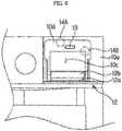
- a part adjacent to the opening 10c of the main body 10may include a non-magnetic portion 10d made of a non-magnetic substance and a magnetic portion 10e made of a magnetic substance, and the water supply door 12 may include magnets 14A and 14B.
- the non-magnetic portion 10dmay be arranged around the opening 10c, and the magnetic portion 10e arranged outside the non-magnetic portion 10d. Accordingly, the water supply door 12 maintains a closed state of the opening 10c by magnetic force acting between the magnets 14A and 14B and the magnetic portion 10e.
- the magnets 14A and 14Bmay be arranged such that most regions thereof face the non-magnetic portion 10d. This enables easy operation of the water supply door 12 with a small force by allowing only a small magnetic force to act between the magnets 14A and 14B and the magnetic portion 10e by spacing the magnetic portion 10e and the magnets 14A and 14B a certain distance from each other.
- the magnets 14A and 14Binclude a first magnet 14A having only a portion of which faces the magnetic portion 10e and the remainder of which faces the non-magnetic portion 10d, and a second magnet 14B, the entirety of which faces the non-magnetic portion 10d, as illustrated in FIG. 6 .
- a part adjacent to the opening 10c of the main body 10may include a button 13, a protrusion distance of which alternately varies depending on a number of times the button 13 is pressed. Accordingly, the button 13 selectively protrudes forward through the water supply door 12 depending on the number of times the button 13 is pressed by a user, thereby pushing the upper end of the water supply door 12. Since the water supply door 12 maintains the state of closing the opening 10c by a small magnetic force acting between the magnets 14A and 14B and the magnetic portion 10e, the water supply door 12 may be pushed, at the upper end thereof, by the button 13 depending on protrusion thereof to be spaced apart from the opening 10c, and the water supply door 12 rotate about the lower end thereof by gravity. Consequently, the opening 10c may be opened.
- the steam generator 22includes a heater (not shown) to apply heat, and generates steam by heating water transferred to the steam generator 22.
- the water supply pump 25may be operated and water may be supplied from the water storage unit 21 through the water supply tube 23 to the steam generator 22, as illustrated in FIG. 3 . Since water supplied to the steam generator 22 is heated and evaporated in the steam generator 22, steam is generated by the steam generator 22. Steam generated by the steam generator 22 may be transferred to both sides of the cooking chamber 10a through two steam supply tubes 27, thereby allowing food to be cooked in the cooking chamber 10a.
- the operation of the water supply pump 25may be stopped.
- the water flow sensing sensor 28 disposed at the water supply tube 23senses whether water moves through the water supply tube 23, thus identifying whether the water supply is blocked. Since the water flow sensing sensor 28 senses whether water is supplied in a state in which water is not supplied to the steam generator 22, the steam generator 22 may be operated more safely.
- the water collection pump 26may be operated. As illustrated in FIG. 4 , residual water in the steam generator 22 is transferred through the water collection tube 24 to the water storage unit 21 depending on the operation of the water collection pump 26. Accordingly, since residual water in the steam generator 22 is collected to the water storage unit 21 to be reused, it may be possible to efficiently use water. Thus, a period between adding water into the water storage container 212 by a user is increased. Therefore, convenience in operating the cooking apparatus is increased.
- a userWhen all water in the water storage container 212 is used, depending on use of the cooking apparatus, a user separates the water storage container 212 from the main body 10 through the opening 10c in the state of opening the opening 10c by rotating the water supply door 12 to put water into the water storage container 212, and mounts the water storage container 212 inside the main body 10 through the opening 10c.
- a portion of watermay unavoidably drop on the inner surface of the water supply door 12 during attachment and/or detachment of the water storage container 212 in opening the water supply door 12.
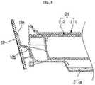
- Drop water dropping on the inner surface of the water supply door 12may be gathered on the inner surface of the water supply door 12 by the guide rib 12a, as illustrated in FIG. 7 , and guided through the opening 10c into the water storage case 211 positioned inside the opening 10c by the guide portion 12b during closing of the opening 10c with the water supply door 12, as illustrated in FIG. 8 . Since water guided into the water storage case 211 may be stored in the drop water storage portion 211a provided at the lower portion of the water storage case 211, it may be possible to prevent drop water from being introduced into other components within the main body 10.
- the drop waterSince drop water generated during attachment and detachment of a water storage container is guided to a water storage case, the drop water may be prevented from being introduced into a main body.
Landscapes
- Engineering & Computer Science (AREA)
- Mechanical Engineering (AREA)
- General Engineering & Computer Science (AREA)
- Chemical & Material Sciences (AREA)
- Combustion & Propulsion (AREA)
- Food Science & Technology (AREA)
- Sustainable Development (AREA)
- Sustainable Energy (AREA)
- Physics & Mathematics (AREA)
- Thermal Sciences (AREA)
- Life Sciences & Earth Sciences (AREA)
- Electric Ovens (AREA)
- Cookers (AREA)
Description
- The present invention relates to a cooking apparatus having a steam supply device to supply steam to a cooking chamber.
- A cooking apparatus has been used in which food is able to be cooked using steam heat. Such a cooking apparatus includes a steam supply device to supply steam to a cooking chamber in which food is cooked.
- The steam supply device includes a water storage unit to store water and a steam generator to generate steam by heating water transferred from the water storage unit, and supplies steam generated by the steam generator to a cooking chamber so as to allow food in the cooking chamber to be cooked by the steam.
EP2083223 discloses a cooker having a cooker main body and a discharged steam cooling unit placed at the top surface of the cooker main body. The operation of the cooker is controlled by a control device.DE102009055146 discloses a steam generation system having a liquid reservoir, an evaporator supplied with liquid from the liquid reservoir and a pump for promoting liquid. The evaporator is connected to the liquid reservoir via the pump and a multi-way valve network. The positions of the valves are switched to fill and empty the evaporator, respectively.DE19912444 discloses a device for electronically monitoring scaling in a device for heating and/or evaporating a liquid. An evaluation unit is connected to at least one flowmeter for evaluating liquid levels within the device.EP2461107 discloses a cooking apparatus with a steam generator and a flow sensing sensor.- Therefore, it is an aspect of the present invention to provide a cooking apparatus having a steam supply device capable of more efficiently utilizing water.
- It is an aspect of the present invention to provide a cooking apparatus capable of preventing drop water generated during attachment and detachment of a water storage container from being introduced into a main body.
- It is an aspect of the present invention to provide a cooking apparatus capable of maintaining a state where an opening, through which a water storage container is attached and detached, is stably closed by a water supply door.
- Additional aspects of the invention will be set forth in part in the description which follows and, in part, will be obvious from the description, or may be learned by practice of the invention.
- According to an aspect of the present invention, there is provided a cooking apparatus according to claim 1.
- Optional features are set out in the dependent claims.
- The steam supply device includes a water supply pump that is disposed at the water supply tube and allows water to be moved from the water storage unit to the steam generator.
- The steam supply device also includes a water collection pump that is disposed at the water collection tube and allows water to be moved from the steam generator to the water storage unit.
- Further, the steam supply device includes a water flow sensing sensor disposed at the water supply tube to sense flow of water.
- The steam supply device may include a steam supply tube to transfer steam generated by the steam generator to the cooking chamber.
- The water storage unit may include a water storage case mounted within the main body and a water storage container that is separately installed to the water storage case, and the main body may include an opening through which the water storage container passes and a water supply door that is rotatably mounted, at a lower end thereof, to a front surface of the main body to open and close the opening during rotation of the water supply door.
- The water supply door may include a guide rib that is provided on an inner surface thereof and is formed in a U-shape oriented downward, and a guide portion protruding inside the water supply door from an inner surface lower portion thereof, a lower end of the guide rib being formed at both sides of the guide portion.
- The water storage case may include a drop water storage portion recessed downward at a lower portion thereof to receive and gather drop water.
- The main body may include a non-magnetic portion made of a non-magnetic substance that is provided in a part adjacent to the opening and a magnetic portion made of a magnetic substance that is provided in the part adjacent to the opening, and the water supply door may include at least one magnet disposed to face the non-magnetic portion.
- The at least one magnet may include a first magnet a portion of that faces the magnetic portion and the remainder of which faces the non-magnetic portion, and a second magnet the entirety of which faces all of the non-magnetic portion.
- The main body may include a button disposed in the part adjacent to the opening, a protrusion length of the button alternately varying depending on the number of times the button is pressed.
- In accordance with an embodiment of the present invention, a cooking apparatus includes a main body provided with a cooking chamber, and a steam supply device generating steam to supply the steam to the cooking chamber, wherein the steam supply device includes a water storage container that is attachable to, and detachable from, the main body, and a steam generator that is supplied with water from the water storage container to generate steam, the main body includes an opening through which the water storage container is attached and detached, a water supply door to open and close the opening, a non-magnetic portion made of a non-magnetic substance that is provided in a part adjacent to the opening, and a magnetic portion made of a magnetic substance that is provided in the part adjacent to the opening, and the water supply door includes at least one magnet disposed to face the non-magnetic portion.
- In accordance with a further embodiment of the present invention, a cooking apparatus includes a main body provided with a cooking chamber, a water storage unit to store water, and a steam generator that is supplied with water from the water storage unit to generate steam, wherein the water storage unit includes a water storage case mounted within the main body and a water storage container that is separately installed to the water storage case, the main body includes an opening through which the water storage container is attached and detached, a water supply door which is rotatably mounted, at a lower end thereof, to the main body to open and close the opening, and the water supply door includes a guide rib that is provided on an inner surface thereof and is formed in a U shape toward downward.
- These and/or other aspects of the invention will become apparent and more readily appreciated from the following description of the embodiments, taken in conjunction with the accompanying drawings of which:
FIG. 1 illustrates a cooking apparatus according to an embodiment of the present invention;FIG. 2 illustrates a steam supply device included in a cooking apparatus according to an exemplary embodiment of the present invention;FIGS. 3 and4 a illustrating an exemplary operation of a steam supply device included in the cooking apparatus according to an embodiment of the present invention;FIG. 5 is an enlarged view of portion A illustrated inFIG. 1 ;FIG. 6 illustrates an exemplary a part adjacent to an opening provided in a main body; andFIGS. 7 and8 illustrate an exemplary opening and closing state of a water supply door included in a cooking apparatus according to an embodiment of the present invention.- Reference will now be made in detail to the embodiments, examples of which are illustrated in the accompanying drawings, wherein like reference numerals refer to the like elements throughout. The embodiments are described below to explain the present invention by referring to the figures.
- A cooking apparatus including a steam supply device according to an embodiment of the present invention is described in detail with reference to the drawings, wherein like reference numerals refer to like elements throughout.
- As illustrated in
FIG. 1 , a cooking apparatus according to an embodiment of the present invention includes amain body 10 provided with acooking chamber 10a into which food to be cooked may be inserted, and adoor 11 mounted on a front surface of themain body 10 to open and close the cooking chamber. Themain body 10 may be provided, at a front surface upper portion thereof, with acontrol panel 10b that may manipulate various conditions such as an output of the cooking apparatus and a cooking time. - As illustrated in
FIGS. 2 and3 , themain body 10 has a built-insteam supply device 20 to generate and supply steam to thecooking chamber 10a, for example, at an upper portion of themain body 10. Thesteam supply device 20 includes awater storage unit 21 and asteam generator 22, wherein thewater storage unit 21 stores water required for a steam generator, and thesteam generator 22 is supplied with water from thewater storage unit 21 and generates steam. Thewater storage unit 21 and thesteam generator 22 may be connected to each other through awater supply tube 23 to guide water of thewater storage unit 21 to thesteam generator 22. Awater collection tube 24 may guide residual water in thesteam generator 22 to thewater storage unit 21. - The
steam generator 22 may be connected withsteam supply tubes 27 to guide steam generated by thesteam generator 22 to thecooking chamber 10a. According to an exemplary embodiment, twosteam supply tubes 27 are provided, and thus steam generated by thesteam generator 22 may be guided through thesteam supply tubes 27 to both sides of thecooking chamber 10a, respectively. - The
steam supply device 20 includes awater supply pump 25, which is disposed at thewater supply tube 23 and allows water to be transferred from thewater storage unit 21 through thewater supply tube 23 to thesteam generator 22, and awater collection pump 26, which is disposed at thewater collection tube 24 and allows residual water in thesteam generator 22 to be collected from thesteam generator 22 through thewater collection tube 24 to thewater storage unit 21. Thewater supply tube 23 may be provided with a waterflow sensing sensor 28 disposed between thewater storage unit 21 and thewater supply pump 25 to sense whether water flows through thewater supply tube 23. - The
water storage unit 21 includes awater storage case 211 mounted within themain body 10 and a movablewater storage container 212, which may be separately installed to thewater storage case 211, and may be attached to, and detached from, themain body 10. Thewater storage case 211 may have an open front side so as to attach and detach thewater storage container 212. Thewater storage case 211 may include, at a lower portion thereof, a dropwater storage portion 211a (see, for example,FIG. 7 ) recessed downward in order to receive and gather drop water generated during attachment and/or detachment of thewater storage container 212. Accordingly, a user may replenish water to be used for thesteam generator 22 by separating thewater storage container 212 from themain body 10, putting water into thewater storage container 212, and mounting thewater storage container 212 to themain body 10. - As illustrated in
FIG. 5 , a side of the front surface upper portion of themain body 10 may be provided with an opening 10c through which thewater storage container 212 is attachable to, and detachable from, thewater storage case 211 mounted within themain body 10. The opening 10c may be provided to correspond to thewater storage case 211, and may be opened and closed by awater supply door 12 that is rotatably mounted on the front surface of themain body 10. Thewater supply door 12 may be rotatably mounted, at a lower end thereof, to themain body 10 to open and close the opening 10c while rotating about the lower end. - The
water supply door 12 may be provided, on an inner surface thereof, with aguide rib 12a, which may formed in a U-shape oriented downward of the water supply door 12 (a U-shape illustrated rearward inFig. 5 ) so as to serve to receive and gather drop water dropping on the inner surface of thewater supply door 12. Thewater supply door 12 may be provided, at an inner surface lower portion thereof, with aguide portion 12b extending rearward, inside the opening 10c so as to have an arc-shaped cross-section. - A lower end portion of the
guide rib 12a may be provided at both sides of theguide portion 12b. Thus, water gathered by theguide rib 12a may be guided into thewater storage case 211 disposed inside the opening 10c by theguide portion 12b. - To maintain a state in which the opening 10c is closed by the
water supply door 12, a part adjacent to the opening 10c of themain body 10 may include anon-magnetic portion 10d made of a non-magnetic substance and amagnetic portion 10e made of a magnetic substance, and thewater supply door 12 may includemagnets non-magnetic portion 10d may be arranged around the opening 10c, and themagnetic portion 10e arranged outside thenon-magnetic portion 10d. Accordingly, thewater supply door 12 maintains a closed state of the opening 10c by magnetic force acting between themagnets magnetic portion 10e. - The
magnets non-magnetic portion 10d. This enables easy operation of thewater supply door 12 with a small force by allowing only a small magnetic force to act between themagnets magnetic portion 10e by spacing themagnetic portion 10e and themagnets - According to an exemplary embodiment, the
magnets first magnet 14A having only a portion of which faces themagnetic portion 10e and the remainder of which faces thenon-magnetic portion 10d, and asecond magnet 14B, the entirety of which faces thenon-magnetic portion 10d, as illustrated inFIG. 6 . - A part adjacent to the
opening 10c of themain body 10 may include abutton 13, a protrusion distance of which alternately varies depending on a number of times thebutton 13 is pressed. Accordingly, thebutton 13 selectively protrudes forward through thewater supply door 12 depending on the number of times thebutton 13 is pressed by a user, thereby pushing the upper end of thewater supply door 12. Since thewater supply door 12 maintains the state of closing theopening 10c by a small magnetic force acting between themagnets magnetic portion 10e, thewater supply door 12 may be pushed, at the upper end thereof, by thebutton 13 depending on protrusion thereof to be spaced apart from theopening 10c, and thewater supply door 12 rotate about the lower end thereof by gravity. Consequently, theopening 10c may be opened. - The
steam generator 22 includes a heater (not shown) to apply heat, and generates steam by heating water transferred to thesteam generator 22. - An exemplary operation of a cooking apparatus is described in detail with reference to the drawings.
- In cooking food using steam, the
water supply pump 25 may be operated and water may be supplied from thewater storage unit 21 through thewater supply tube 23 to thesteam generator 22, as illustrated inFIG. 3 . Since water supplied to thesteam generator 22 is heated and evaporated in thesteam generator 22, steam is generated by thesteam generator 22. Steam generated by thesteam generator 22 may be transferred to both sides of thecooking chamber 10a through twosteam supply tubes 27, thereby allowing food to be cooked in thecooking chamber 10a. - As illustrated in
FIG. 4 , after cooking of food is completed through steam, the operation of thewater supply pump 25 may be stopped. The waterflow sensing sensor 28 disposed at thewater supply tube 23 senses whether water moves through thewater supply tube 23, thus identifying whether the water supply is blocked. Since the waterflow sensing sensor 28 senses whether water is supplied in a state in which water is not supplied to thesteam generator 22, thesteam generator 22 may be operated more safely. - After a blocking to the water supply is identified, the
water collection pump 26 may be operated. As illustrated inFIG. 4 , residual water in thesteam generator 22 is transferred through thewater collection tube 24 to thewater storage unit 21 depending on the operation of thewater collection pump 26. Accordingly, since residual water in thesteam generator 22 is collected to thewater storage unit 21 to be reused, it may be possible to efficiently use water. Thus, a period between adding water into thewater storage container 212 by a user is increased. Therefore, convenience in operating the cooking apparatus is increased. - When all water in the
water storage container 212 is used, depending on use of the cooking apparatus, a user separates thewater storage container 212 from themain body 10 through theopening 10c in the state of opening theopening 10c by rotating thewater supply door 12 to put water into thewater storage container 212, and mounts thewater storage container 212 inside themain body 10 through theopening 10c. - A portion of water may unavoidably drop on the inner surface of the
water supply door 12 during attachment and/or detachment of thewater storage container 212 in opening thewater supply door 12. Drop water dropping on the inner surface of thewater supply door 12 may be gathered on the inner surface of thewater supply door 12 by theguide rib 12a, as illustrated inFIG. 7 , and guided through theopening 10c into thewater storage case 211 positioned inside theopening 10c by theguide portion 12b during closing of theopening 10c with thewater supply door 12, as illustrated inFIG. 8 . Since water guided into thewater storage case 211 may be stored in the dropwater storage portion 211a provided at the lower portion of thewater storage case 211, it may be possible to prevent drop water from being introduced into other components within themain body 10. - Since residual water in a steam generator may be collected to a water storage unit for reuse, it may be possible to efficiently use water, and thus a water supply period may be increased.
- Since drop water generated during attachment and detachment of a water storage container is guided to a water storage case, the drop water may be prevented from being introduced into a main body.
- Furthermore, it may be possible to maintain a state in which a water supply door stably closes an opening by magnetic force acting between a magnet provided in the water supply door and a magnetic portion provided in a part adjacent to the opening.
- Although a few embodiments of the present invention have been shown and described, it would be appreciated by those skilled in the art that changes may be made in these embodiments without departing from the principles of the invention, the scope of which is defined in the claims.
Claims (8)
- A cooking apparatus comprising:a main body (10) provided with a cooking chamber (10a); anda steam supply device (20) generating steam to supply the steam to the cooking chamber (10a),wherein the steam supply device (20) comprises a water storage unit (21) to store water, a steam generator (22) that is supplied with water from the water storage unit (21) to generate steam, a water supply tube (23) to transfer water in the water storage unit (21) to the steam generator (22), a water supply pump (25) that is disposed at the water supply tube (23) and allows water to be moved from the water storage unit (21) to the steam generator (22), a water collection tube (24) to transfer residual water in the steam generator (22) to the water storage unit (21), a water collection pump (26) that is disposed at the water collection tube (24) and allows water to be moved from the steam generator (22) to the water storage unit (21), and a water flow sensing sensor (28) disposed at the water supply tube (23),wherein the water flow sensing sensor (28) is configured to sense whether flow of water to the steam generator (22) is blocked, andwherein the cooking apparatus is further configured to operate the water collection pump (26) if the flow of water is blocked.
- The cooking apparatus according to claim 1, wherein the steam supply device (20) comprises a steam supply tube (27) to transfer steam generated by the steam generator (22) to the cooking chamber (10a).
- The cooking apparatus according to any one of the preceding claims, wherein:the water storage unit (21) comprises a water storage case (211) mounted within the main body (10) and a water storage container (212) that is separately installed to the water storage case (211); andthe main body (10) comprises an opening (10c) through which the water storage container passes (212), and a water supply door (12) that is rotatably mounted, at a lower end thereof, to a front surface of the main body (10) to open and close the opening (10c) during rotation of the water supply door (12).
- The cooking apparatus according to claim 3, wherein the water supply door (12) comprises a guide rib (12a) that is provided on an inner surface thereof and is formed in a U-shape oriented downward, and a guide portion (12b) protruding inside the water supply door (12) from an inner surface lower portion thereof, a lower end of the guide rib (12a) being formed at both sides of the guide portion (12b).
- The cooking apparatus according to claim 3 or 4, wherein the water storage case (211) comprises a drop water storage portion (211a) recessed downward at a lower portion thereof to receive and gather drop water.
- The cooking apparatus according to any one of claims 3 to 5, wherein:the main body (10) comprises a non-magnetic portion (10d) made of a non-magnetic substance that is provided in a part adjacent to the opening (10c) and a magnetic portion (10e) made of a magnetic substance that is provided in the part adjacent to the opening (10c); andthe water supply door (12) comprises at least one magnet (14A, 14B) disposed to face the non-magnetic portion (10d).
- The cooking apparatus according to claim 6, wherein the at least one magnet (14A, 14B) comprises a first magnet (14A) a portion of which faces the magnetic portion (10e) and the remainder of which faces the non-magnetic portion (10d), and a second magnet (14B) the entirety of which faces all of the non-magnetic portion (10d).
- The cooking apparatus according to claim 6 or 7, wherein the main body (10) comprises a button (13) disposed in the part adjacent to the opening (10c), a protrusion length of the button (13) alternately varying depending on the number of times the button (13) is pressed.
Applications Claiming Priority (1)
| Application Number | Priority Date | Filing Date | Title |
|---|---|---|---|
| KR1020120150759AKR101981674B1 (en) | 2012-12-21 | 2012-12-21 | Cooking apparatus |
Publications (3)
| Publication Number | Publication Date |
|---|---|
| EP2746682A2 EP2746682A2 (en) | 2014-06-25 |
| EP2746682A3 EP2746682A3 (en) | 2014-10-29 |
| EP2746682B1true EP2746682B1 (en) | 2021-01-27 |
Family
ID=49724973
Family Applications (1)
| Application Number | Title | Priority Date | Filing Date |
|---|---|---|---|
| EP13194993.5AActiveEP2746682B1 (en) | 2012-12-21 | 2013-11-29 | Cooking apparatus |
Country Status (4)
| Country | Link |
|---|---|
| US (1) | US9581339B2 (en) |
| EP (1) | EP2746682B1 (en) |
| KR (1) | KR101981674B1 (en) |
| CN (1) | CN103876612A (en) |
Families Citing this family (31)
| Publication number | Priority date | Publication date | Assignee | Title |
|---|---|---|---|---|
| KR101981674B1 (en)* | 2012-12-21 | 2019-05-24 | 삼성전자주식회사 | Cooking apparatus |
| CN105816017B (en)* | 2016-04-12 | 2018-07-06 | 广东美的厨房电器制造有限公司 | A kind of steam cooking apparatus and its control method |
| CN105768857A (en)* | 2016-05-30 | 2016-07-20 | 广东美的厨房电器制造有限公司 | Steam cooking device |
| DE102016215650A1 (en)* | 2016-08-19 | 2018-02-22 | BSH Hausgeräte GmbH | Haushaltsgargerät |
| KR102357903B1 (en)* | 2017-05-19 | 2022-02-03 | 삼성전자주식회사 | Control method of cooking apparatus |
| CN109247896B (en)* | 2017-07-14 | 2021-06-25 | 青岛海尔洗碗机有限公司 | Dishwasher door body guide device and dishwasher |
| WO2019032876A1 (en) | 2017-08-09 | 2019-02-14 | Sharkninja Operating Llc | Cooking device and components thereof |
| JP6854426B2 (en)* | 2018-02-28 | 2021-04-07 | パナソニックIpマネジメント株式会社 | Cooker |
| EP3553394A1 (en) | 2018-04-09 | 2019-10-16 | Whirlpool Corporation | Steam generating system |
| USD914447S1 (en) | 2018-06-19 | 2021-03-30 | Sharkninja Operating Llc | Air diffuser |
| KR102611409B1 (en)* | 2018-07-26 | 2023-12-06 | 엘지전자 주식회사 | Pump assembly and cooking appliance therewith |
| USD934027S1 (en) | 2018-08-09 | 2021-10-26 | Sharkninja Operating Llc | Reversible cooking rack |
| USD903413S1 (en) | 2018-08-09 | 2020-12-01 | Sharkninja Operating Llc | Cooking basket |
| USD883015S1 (en) | 2018-08-09 | 2020-05-05 | Sharkninja Operating Llc | Food preparation device and parts thereof |
| USD883014S1 (en) | 2018-08-09 | 2020-05-05 | Sharkninja Operating Llc | Food preparation device |
| KR102133286B1 (en) | 2018-12-14 | 2020-07-13 | 엘지전자 주식회사 | Electronic cooking device possible automatic cleaning of kitchen ctructure |
| US11051654B2 (en) | 2019-02-25 | 2021-07-06 | Sharkninja Operating Llc | Cooking device and components thereof |
| WO2020176477A1 (en) | 2019-02-25 | 2020-09-03 | Sharkninja Operating Llc | Cooking system with guard |
| DE102019206323A1 (en)* | 2019-05-03 | 2020-11-05 | BSH Hausgeräte GmbH | Steam treatment device and method for cleaning a steam treatment device |
| USD982375S1 (en) | 2019-06-06 | 2023-04-04 | Sharkninja Operating Llc | Food preparation device |
| USD918654S1 (en) | 2019-06-06 | 2021-05-11 | Sharkninja Operating Llc | Grill plate |
| CN110384393B (en)* | 2019-06-26 | 2021-07-20 | 广东美的厨房电器制造有限公司 | Water collecting device for steam cooking apparatus and steam cooking apparatus having the same |
| EP4033904A1 (en) | 2019-09-23 | 2022-08-03 | Anova Applied Electronics, Inc. | Wet bulb temperature sensor system and method for direct measurement of wet bulb temperature in an oven |
| US11678765B2 (en) | 2020-03-30 | 2023-06-20 | Sharkninja Operating Llc | Cooking device and components thereof |
| US20230363566A1 (en)* | 2020-09-28 | 2023-11-16 | Anova Applied Electronics, Inc. | Combination oven |
| US20220183496A1 (en)* | 2020-12-11 | 2022-06-16 | Whirlpool Corporation | Modular steam generator |
| KR102421938B1 (en)* | 2020-12-11 | 2022-07-15 | 김봉수 | Steam toaster |
| US12226040B2 (en) | 2022-01-04 | 2025-02-18 | Whirlpool Corporation | Steam oven with check valve at water inlet for steam backflow prevention |
| KR102811154B1 (en)* | 2022-01-06 | 2025-05-26 | 삼성전자주식회사 | Cooking appliance |
| EP4390234A4 (en)* | 2022-01-06 | 2024-12-25 | Samsung Electronics Co., Ltd. | COOKING APPLIANCE |
| WO2023132503A1 (en)* | 2022-01-06 | 2023-07-13 | 삼성전자주식회사 | Cooking apparatus |
Citations (1)
| Publication number | Priority date | Publication date | Assignee | Title |
|---|---|---|---|---|
| EP2461107A1 (en)* | 2010-12-06 | 2012-06-06 | Miele & Cie. KG | Cooking device and method for operating same |
Family Cites Families (31)
| Publication number | Priority date | Publication date | Assignee | Title |
|---|---|---|---|---|
| AU3543789A (en)* | 1988-05-18 | 1989-12-12 | Mamoru Houkuwa | Structure of double steam oven |
| SE509732C2 (en)* | 1996-06-18 | 1999-03-01 | Tsp Medical Ab | Steam generator with controlled supply and removal of water |
| DE19912444C2 (en) | 1999-03-19 | 2001-11-29 | Rational Ag | Steam generator of a cooking device with a device for electronic calcification monitoring |
| DE10043771C2 (en)* | 2000-07-03 | 2003-07-17 | Rational Ag | Cooking appliance with water volume registration |
| KR100439065B1 (en)* | 2002-04-04 | 2004-07-05 | 동화시스템(주) | Apparatus for receiving water in a steam oven |
| DE10234625B4 (en) | 2002-07-29 | 2005-02-24 | Rational Ag | Steam generator with reactor for Kalkkristallkeimbildung |
| KR20040056161A (en)* | 2002-12-23 | 2004-06-30 | 삼성전자주식회사 | Microwave oven |
| DE102004006973A1 (en) | 2003-02-21 | 2004-10-21 | BSH Bosch und Siemens Hausgeräte GmbH | Steam cooking appliance for operating with a controlled volume flow of fresh water has a fresh water supply pipe |
| KR101041071B1 (en)* | 2003-12-30 | 2011-06-13 | 삼성전자주식회사 | Heating cooker |
| KR101132331B1 (en)* | 2004-07-14 | 2012-04-05 | 삼성전자주식회사 | Heating cooker and control method thereof |
| KR20060006472A (en)* | 2004-07-16 | 2006-01-19 | 삼성전자주식회사 | Heating cooker |
| KR100629336B1 (en)* | 2004-11-05 | 2006-09-29 | 엘지전자 주식회사 | Steam generator in steam oven |
| US7537004B2 (en)* | 2005-05-03 | 2009-05-26 | Whirlpool Corporation | Steam oven with fluid supply and drain vessel |
| US7326891B2 (en)* | 2005-06-08 | 2008-02-05 | Samsung Electronics Co., Ltd. | Steam generation apparatus using induction heating and oven including the same |
| JP3876267B1 (en)* | 2005-08-01 | 2007-01-31 | シャープ株式会社 | Cooker |
| US20070062927A1 (en)* | 2005-09-06 | 2007-03-22 | Sells Joel M | Steam generator system for a household oven |
| US7348520B2 (en)* | 2006-03-20 | 2008-03-25 | Ching-Hsiang Wang | Oven with a heat circulating device |
| JP4111979B2 (en)* | 2006-08-04 | 2008-07-02 | シャープ株式会社 | Cooker |
| US20090250452A1 (en)* | 2006-08-08 | 2009-10-08 | Sze-Man Tse | Steam Convection Oven |
| KR101041078B1 (en)* | 2006-09-27 | 2011-06-13 | 삼성전자주식회사 | Cooking device and control method |
| KR101041079B1 (en)* | 2006-09-28 | 2011-06-13 | 삼성전자주식회사 | Leveling unit, steam generator with same, and heating cooker with steam generator |
| KR101269270B1 (en)* | 2006-09-28 | 2013-05-29 | 엘지전자 주식회사 | An opening and shutting Structure of home-bar door for refrigerator |
| KR101041077B1 (en)* | 2006-09-28 | 2011-06-13 | 삼성전자주식회사 | Steam generator and heating cooking device having same |
| JP4311688B2 (en)* | 2006-11-02 | 2009-08-12 | シャープ株式会社 | Exhaust steam diluting apparatus and cooking device equipped with the same |
| KR20080065134A (en)* | 2007-01-08 | 2008-07-11 | 삼성전자주식회사 | Water level sensor, steam generator with same, cooking apparatus with same and generator and control method |
| KR101059818B1 (en)* | 2007-01-08 | 2011-08-26 | 삼성전자주식회사 | Steam generator and cooking apparatus having same and control method thereof |
| DE102007016501A1 (en)* | 2007-03-26 | 2008-10-02 | E.G.O. Elektro-Gerätebau GmbH | Method and steam cooking appliance for controlling cooking processes in a cooking chamber |
| US8288690B2 (en)* | 2009-01-16 | 2012-10-16 | Mag Aerospace Industries, Inc. | Oven steam generator systems and methods |
| JP5358677B2 (en)* | 2009-03-30 | 2013-12-04 | シャープ株式会社 | Cooker |
| DE102009055146A1 (en) | 2009-12-22 | 2011-06-30 | BSH Bosch und Siemens Hausgeräte GmbH, 81739 | Steam generation system for household appliance, particularly steam equipment, has liquid reservoir, evaporator supplied with liquid from liquid reservoir and pump for promoting liquid |
| KR101981674B1 (en)* | 2012-12-21 | 2019-05-24 | 삼성전자주식회사 | Cooking apparatus |
- 2012
- 2012-12-21KRKR1020120150759Apatent/KR101981674B1/enactiveActive
- 2013
- 2013-11-22USUS14/087,787patent/US9581339B2/enactiveActive
- 2013-11-29EPEP13194993.5Apatent/EP2746682B1/enactiveActive
- 2013-12-20CNCN201310711376.9Apatent/CN103876612A/enactivePending
Patent Citations (1)
| Publication number | Priority date | Publication date | Assignee | Title |
|---|---|---|---|---|
| EP2461107A1 (en)* | 2010-12-06 | 2012-06-06 | Miele & Cie. KG | Cooking device and method for operating same |
Also Published As
| Publication number | Publication date |
|---|---|
| KR20140081219A (en) | 2014-07-01 |
| US9581339B2 (en) | 2017-02-28 |
| KR101981674B1 (en) | 2019-05-24 |
| EP2746682A2 (en) | 2014-06-25 |
| EP2746682A3 (en) | 2014-10-29 |
| US20140175085A1 (en) | 2014-06-26 |
| CN103876612A (en) | 2014-06-25 |
Similar Documents
| Publication | Publication Date | Title |
|---|---|---|
| EP2746682B1 (en) | Cooking apparatus | |
| EP2775216B1 (en) | Steam cooking appliance | |
| EP2775217B1 (en) | Steam cooking appliance | |
| EP3259394B1 (en) | A hand-held garment steamer with scale collection chamber | |
| EP3639706B1 (en) | Method for operating a steam cooking appliance and steam cooking appliance | |
| KR101132331B1 (en) | Heating cooker and control method thereof | |
| EP2645912B1 (en) | Simple user-interface for a beverage machine | |
| US20200146498A1 (en) | Cooking appliance | |
| KR20120122141A (en) | Steam cooking apparatus | |
| EP2674700B1 (en) | Method for controlling refrigerator | |
| EP2703739B1 (en) | A cooking oven with an oven cavity and a steam cooking arrangement | |
| US20070256444A1 (en) | Water supplying apparatus and refrigerator having the same | |
| WO2011114327A2 (en) | Heater for on-demand hot water dispensing | |
| KR101074556B1 (en) | Steam Cooker | |
| KR102067828B1 (en) | A steam oven range | |
| KR101292674B1 (en) | Steamer unit for rice cake and steamer sytem for rice cake | |
| JP2009079887A (en) | Cooker | |
| JP7423095B2 (en) | water server | |
| KR20140109589A (en) | A steam oven range | |
| KR20100112919A (en) | A cooker | |
| KR101615375B1 (en) | A steam generating device and a cooker comprising in the same | |
| KR20110006894A (en) | Cooker | |
| JP2016178956A (en) | Beverage extraction apparatus | |
| JP5289789B2 (en) | Beverage supply equipment | |
| JP4576468B2 (en) | Liquid tank and cooker |
Legal Events
| Date | Code | Title | Description |
|---|---|---|---|
| PUAI | Public reference made under article 153(3) epc to a published international application that has entered the european phase | Free format text:ORIGINAL CODE: 0009012 | |
| 17P | Request for examination filed | Effective date:20131129 | |
| AK | Designated contracting states | Kind code of ref document:A2 Designated state(s):AL AT BE BG CH CY CZ DE DK EE ES FI FR GB GR HR HU IE IS IT LI LT LU LV MC MK MT NL NO PL PT RO RS SE SI SK SM TR | |
| AX | Request for extension of the european patent | Extension state:BA ME | |
| PUAL | Search report despatched | Free format text:ORIGINAL CODE: 0009013 | |
| AK | Designated contracting states | Kind code of ref document:A3 Designated state(s):AL AT BE BG CH CY CZ DE DK EE ES FI FR GB GR HR HU IE IS IT LI LT LU LV MC MK MT NL NO PL PT RO RS SE SI SK SM TR | |
| AX | Request for extension of the european patent | Extension state:BA ME | |
| RIC1 | Information provided on ipc code assigned before grant | Ipc:F24C 15/32 20060101AFI20140926BHEP | |
| R17P | Request for examination filed (corrected) | Effective date:20150429 | |
| RBV | Designated contracting states (corrected) | Designated state(s):AL AT BE BG CH CY CZ DE DK EE ES FI FR GB GR HR HU IE IS IT LI LT LU LV MC MK MT NL NO PL PT RO RS SE SI SK SM TR | |
| 17Q | First examination report despatched | Effective date:20160511 | |
| STAA | Information on the status of an ep patent application or granted ep patent | Free format text:STATUS: EXAMINATION IS IN PROGRESS | |
| GRAP | Despatch of communication of intention to grant a patent | Free format text:ORIGINAL CODE: EPIDOSNIGR1 | |
| STAA | Information on the status of an ep patent application or granted ep patent | Free format text:STATUS: GRANT OF PATENT IS INTENDED | |
| INTG | Intention to grant announced | Effective date:20200806 | |
| GRAS | Grant fee paid | Free format text:ORIGINAL CODE: EPIDOSNIGR3 | |
| GRAA | (expected) grant | Free format text:ORIGINAL CODE: 0009210 | |
| STAA | Information on the status of an ep patent application or granted ep patent | Free format text:STATUS: THE PATENT HAS BEEN GRANTED | |
| AK | Designated contracting states | Kind code of ref document:B1 Designated state(s):AL AT BE BG CH CY CZ DE DK EE ES FI FR GB GR HR HU IE IS IT LI LT LU LV MC MK MT NL NO PL PT RO RS SE SI SK SM TR | |
| RAP1 | Party data changed (applicant data changed or rights of an application transferred) | Owner name:SAMSUNG ELECTRONICS CO., LTD. | |
| REG | Reference to a national code | Ref country code:GB Ref legal event code:FG4D | |
| REG | Reference to a national code | Ref country code:CH Ref legal event code:EP | |
| REG | Reference to a national code | Ref country code:AT Ref legal event code:REF Ref document number:1358694 Country of ref document:AT Kind code of ref document:T Effective date:20210215 | |
| REG | Reference to a national code | Ref country code:IE Ref legal event code:FG4D | |
| REG | Reference to a national code | Ref country code:DE Ref legal event code:R096 Ref document number:602013075475 Country of ref document:DE | |
| REG | Reference to a national code | Ref country code:NL Ref legal event code:MP Effective date:20210127 | |
| REG | Reference to a national code | Ref country code:LT Ref legal event code:MG9D | |
| REG | Reference to a national code | Ref country code:AT Ref legal event code:MK05 Ref document number:1358694 Country of ref document:AT Kind code of ref document:T Effective date:20210127 | |
| PG25 | Lapsed in a contracting state [announced via postgrant information from national office to epo] | Ref country code:BG Free format text:LAPSE BECAUSE OF FAILURE TO SUBMIT A TRANSLATION OF THE DESCRIPTION OR TO PAY THE FEE WITHIN THE PRESCRIBED TIME-LIMIT Effective date:20210427 Ref country code:NO Free format text:LAPSE BECAUSE OF FAILURE TO SUBMIT A TRANSLATION OF THE DESCRIPTION OR TO PAY THE FEE WITHIN THE PRESCRIBED TIME-LIMIT Effective date:20210427 Ref country code:NL Free format text:LAPSE BECAUSE OF FAILURE TO SUBMIT A TRANSLATION OF THE DESCRIPTION OR TO PAY THE FEE WITHIN THE PRESCRIBED TIME-LIMIT Effective date:20210127 Ref country code:HR Free format text:LAPSE BECAUSE OF FAILURE TO SUBMIT A TRANSLATION OF THE DESCRIPTION OR TO PAY THE FEE WITHIN THE PRESCRIBED TIME-LIMIT Effective date:20210127 Ref country code:FI Free format text:LAPSE BECAUSE OF FAILURE TO SUBMIT A TRANSLATION OF THE DESCRIPTION OR TO PAY THE FEE WITHIN THE PRESCRIBED TIME-LIMIT Effective date:20210127 Ref country code:GR Free format text:LAPSE BECAUSE OF FAILURE TO SUBMIT A TRANSLATION OF THE DESCRIPTION OR TO PAY THE FEE WITHIN THE PRESCRIBED TIME-LIMIT Effective date:20210428 Ref country code:PT Free format text:LAPSE BECAUSE OF FAILURE TO SUBMIT A TRANSLATION OF THE DESCRIPTION OR TO PAY THE FEE WITHIN THE PRESCRIBED TIME-LIMIT Effective date:20210527 Ref country code:LT Free format text:LAPSE BECAUSE OF FAILURE TO SUBMIT A TRANSLATION OF THE DESCRIPTION OR TO PAY THE FEE WITHIN THE PRESCRIBED TIME-LIMIT Effective date:20210127 | |
| PG25 | Lapsed in a contracting state [announced via postgrant information from national office to epo] | Ref country code:SE Free format text:LAPSE BECAUSE OF FAILURE TO SUBMIT A TRANSLATION OF THE DESCRIPTION OR TO PAY THE FEE WITHIN THE PRESCRIBED TIME-LIMIT Effective date:20210127 Ref country code:RS Free format text:LAPSE BECAUSE OF FAILURE TO SUBMIT A TRANSLATION OF THE DESCRIPTION OR TO PAY THE FEE WITHIN THE PRESCRIBED TIME-LIMIT Effective date:20210127 Ref country code:PL Free format text:LAPSE BECAUSE OF FAILURE TO SUBMIT A TRANSLATION OF THE DESCRIPTION OR TO PAY THE FEE WITHIN THE PRESCRIBED TIME-LIMIT Effective date:20210127 Ref country code:LV Free format text:LAPSE BECAUSE OF FAILURE TO SUBMIT A TRANSLATION OF THE DESCRIPTION OR TO PAY THE FEE WITHIN THE PRESCRIBED TIME-LIMIT Effective date:20210127 Ref country code:AT Free format text:LAPSE BECAUSE OF FAILURE TO SUBMIT A TRANSLATION OF THE DESCRIPTION OR TO PAY THE FEE WITHIN THE PRESCRIBED TIME-LIMIT Effective date:20210127 | |
| PG25 | Lapsed in a contracting state [announced via postgrant information from national office to epo] | Ref country code:IS Free format text:LAPSE BECAUSE OF FAILURE TO SUBMIT A TRANSLATION OF THE DESCRIPTION OR TO PAY THE FEE WITHIN THE PRESCRIBED TIME-LIMIT Effective date:20210527 | |
| REG | Reference to a national code | Ref country code:DE Ref legal event code:R097 Ref document number:602013075475 Country of ref document:DE | |
| PG25 | Lapsed in a contracting state [announced via postgrant information from national office to epo] | Ref country code:EE Free format text:LAPSE BECAUSE OF FAILURE TO SUBMIT A TRANSLATION OF THE DESCRIPTION OR TO PAY THE FEE WITHIN THE PRESCRIBED TIME-LIMIT Effective date:20210127 Ref country code:CZ Free format text:LAPSE BECAUSE OF FAILURE TO SUBMIT A TRANSLATION OF THE DESCRIPTION OR TO PAY THE FEE WITHIN THE PRESCRIBED TIME-LIMIT Effective date:20210127 Ref country code:SM Free format text:LAPSE BECAUSE OF FAILURE TO SUBMIT A TRANSLATION OF THE DESCRIPTION OR TO PAY THE FEE WITHIN THE PRESCRIBED TIME-LIMIT Effective date:20210127 | |
| PG25 | Lapsed in a contracting state [announced via postgrant information from national office to epo] | Ref country code:ES Free format text:LAPSE BECAUSE OF FAILURE TO SUBMIT A TRANSLATION OF THE DESCRIPTION OR TO PAY THE FEE WITHIN THE PRESCRIBED TIME-LIMIT Effective date:20210127 Ref country code:DK Free format text:LAPSE BECAUSE OF FAILURE TO SUBMIT A TRANSLATION OF THE DESCRIPTION OR TO PAY THE FEE WITHIN THE PRESCRIBED TIME-LIMIT Effective date:20210127 Ref country code:SK Free format text:LAPSE BECAUSE OF FAILURE TO SUBMIT A TRANSLATION OF THE DESCRIPTION OR TO PAY THE FEE WITHIN THE PRESCRIBED TIME-LIMIT Effective date:20210127 Ref country code:RO Free format text:LAPSE BECAUSE OF FAILURE TO SUBMIT A TRANSLATION OF THE DESCRIPTION OR TO PAY THE FEE WITHIN THE PRESCRIBED TIME-LIMIT Effective date:20210127 | |
| PLBE | No opposition filed within time limit | Free format text:ORIGINAL CODE: 0009261 | |
| STAA | Information on the status of an ep patent application or granted ep patent | Free format text:STATUS: NO OPPOSITION FILED WITHIN TIME LIMIT | |
| 26N | No opposition filed | Effective date:20211028 | |
| PG25 | Lapsed in a contracting state [announced via postgrant information from national office to epo] | Ref country code:AL Free format text:LAPSE BECAUSE OF FAILURE TO SUBMIT A TRANSLATION OF THE DESCRIPTION OR TO PAY THE FEE WITHIN THE PRESCRIBED TIME-LIMIT Effective date:20210127 | |
| PG25 | Lapsed in a contracting state [announced via postgrant information from national office to epo] | Ref country code:SI Free format text:LAPSE BECAUSE OF FAILURE TO SUBMIT A TRANSLATION OF THE DESCRIPTION OR TO PAY THE FEE WITHIN THE PRESCRIBED TIME-LIMIT Effective date:20210127 | |
| PG25 | Lapsed in a contracting state [announced via postgrant information from national office to epo] | Ref country code:IT Free format text:LAPSE BECAUSE OF FAILURE TO SUBMIT A TRANSLATION OF THE DESCRIPTION OR TO PAY THE FEE WITHIN THE PRESCRIBED TIME-LIMIT Effective date:20210127 | |
| PG25 | Lapsed in a contracting state [announced via postgrant information from national office to epo] | Ref country code:IS Free format text:LAPSE BECAUSE OF FAILURE TO SUBMIT A TRANSLATION OF THE DESCRIPTION OR TO PAY THE FEE WITHIN THE PRESCRIBED TIME-LIMIT Effective date:20210527 | |
| PG25 | Lapsed in a contracting state [announced via postgrant information from national office to epo] | Ref country code:MC Free format text:LAPSE BECAUSE OF FAILURE TO SUBMIT A TRANSLATION OF THE DESCRIPTION OR TO PAY THE FEE WITHIN THE PRESCRIBED TIME-LIMIT Effective date:20210127 | |
| REG | Reference to a national code | Ref country code:CH Ref legal event code:PL | |
| PG25 | Lapsed in a contracting state [announced via postgrant information from national office to epo] | Ref country code:LU Free format text:LAPSE BECAUSE OF NON-PAYMENT OF DUE FEES Effective date:20211129 Ref country code:BE Free format text:LAPSE BECAUSE OF NON-PAYMENT OF DUE FEES Effective date:20211130 | |
| REG | Reference to a national code | Ref country code:BE Ref legal event code:MM Effective date:20211130 | |
| PG25 | Lapsed in a contracting state [announced via postgrant information from national office to epo] | Ref country code:LI Free format text:LAPSE BECAUSE OF NON-PAYMENT OF DUE FEES Effective date:20211130 Ref country code:CH Free format text:LAPSE BECAUSE OF NON-PAYMENT OF DUE FEES Effective date:20211130 | |
| PG25 | Lapsed in a contracting state [announced via postgrant information from national office to epo] | Ref country code:IE Free format text:LAPSE BECAUSE OF NON-PAYMENT OF DUE FEES Effective date:20211129 | |
| PG25 | Lapsed in a contracting state [announced via postgrant information from national office to epo] | Ref country code:FR Free format text:LAPSE BECAUSE OF NON-PAYMENT OF DUE FEES Effective date:20211130 | |
| PGFP | Annual fee paid to national office [announced via postgrant information from national office to epo] | Ref country code:GB Payment date:20221020 Year of fee payment:10 | |
| PG25 | Lapsed in a contracting state [announced via postgrant information from national office to epo] | Ref country code:HU Free format text:LAPSE BECAUSE OF FAILURE TO SUBMIT A TRANSLATION OF THE DESCRIPTION OR TO PAY THE FEE WITHIN THE PRESCRIBED TIME-LIMIT; INVALID AB INITIO Effective date:20131129 | |
| PG25 | Lapsed in a contracting state [announced via postgrant information from national office to epo] | Ref country code:CY Free format text:LAPSE BECAUSE OF FAILURE TO SUBMIT A TRANSLATION OF THE DESCRIPTION OR TO PAY THE FEE WITHIN THE PRESCRIBED TIME-LIMIT Effective date:20210127 | |
| PG25 | Lapsed in a contracting state [announced via postgrant information from national office to epo] | Ref country code:MK Free format text:LAPSE BECAUSE OF FAILURE TO SUBMIT A TRANSLATION OF THE DESCRIPTION OR TO PAY THE FEE WITHIN THE PRESCRIBED TIME-LIMIT Effective date:20210127 | |
| PG25 | Lapsed in a contracting state [announced via postgrant information from national office to epo] | Ref country code:TR Free format text:LAPSE BECAUSE OF FAILURE TO SUBMIT A TRANSLATION OF THE DESCRIPTION OR TO PAY THE FEE WITHIN THE PRESCRIBED TIME-LIMIT Effective date:20210127 | |
| GBPC | Gb: european patent ceased through non-payment of renewal fee | Effective date:20231129 | |
| PG25 | Lapsed in a contracting state [announced via postgrant information from national office to epo] | Ref country code:MT Free format text:LAPSE BECAUSE OF FAILURE TO SUBMIT A TRANSLATION OF THE DESCRIPTION OR TO PAY THE FEE WITHIN THE PRESCRIBED TIME-LIMIT Effective date:20210127 | |
| PG25 | Lapsed in a contracting state [announced via postgrant information from national office to epo] | Ref country code:GB Free format text:LAPSE BECAUSE OF NON-PAYMENT OF DUE FEES Effective date:20231129 | |
| PG25 | Lapsed in a contracting state [announced via postgrant information from national office to epo] | Ref country code:GB Free format text:LAPSE BECAUSE OF NON-PAYMENT OF DUE FEES Effective date:20231129 | |
| PGFP | Annual fee paid to national office [announced via postgrant information from national office to epo] | Ref country code:DE Payment date:20241021 Year of fee payment:12 |