EP2746010A1 - Chopping aid device for use in chopping of firewood - Google Patents
Chopping aid device for use in chopping of firewoodDownload PDFInfo
- Publication number
- EP2746010A1 EP2746010A1EP13197593.0AEP13197593AEP2746010A1EP 2746010 A1EP2746010 A1EP 2746010A1EP 13197593 AEP13197593 AEP 13197593AEP 2746010 A1EP2746010 A1EP 2746010A1
- Authority
- EP
- European Patent Office
- Prior art keywords
- aid device
- frame
- chopping
- spikes
- chopping aid
- Prior art date
- Legal status (The legal status is an assumption and is not a legal conclusion. Google has not performed a legal analysis and makes no representation as to the accuracy of the status listed.)
- Granted
Links
- 239000002023woodSubstances0.000claimsabstractdescription46
- 239000000463materialSubstances0.000claimsdescription8
- 230000002093peripheral effectEffects0.000claimsdescription7
- 239000011324beadSubstances0.000claimsdescription5
- 239000013536elastomeric materialSubstances0.000claimsdescription3
- 239000004952PolyamideSubstances0.000description3
- -1PolypropylenePolymers0.000description3
- 229920002647polyamidePolymers0.000description3
- 239000004698PolyethyleneSubstances0.000description2
- 239000004743PolypropyleneSubstances0.000description2
- 230000006378damageEffects0.000description2
- 239000003365glass fiberSubstances0.000description2
- 238000002347injectionMethods0.000description2
- 239000007924injectionSubstances0.000description2
- 229920001707polybutylene terephthalatePolymers0.000description2
- 229920000573polyethylenePolymers0.000description2
- 229920001155polypropylenePolymers0.000description2
- 229920002725thermoplastic elastomerPolymers0.000description2
- 208000027418Wounds and injuryDiseases0.000description1
- 238000005452bendingMethods0.000description1
- 230000003670easy-to-cleanEffects0.000description1
- 229920001971elastomerPolymers0.000description1
- 230000005484gravityEffects0.000description1
- 238000001746injection mouldingMethods0.000description1
- 208000014674injuryDiseases0.000description1
- 210000003127kneeAnatomy0.000description1
- 210000002414legAnatomy0.000description1
- 238000004519manufacturing processMethods0.000description1
- 238000000034methodMethods0.000description1
- 238000000465mouldingMethods0.000description1
- 230000000750progressive effectEffects0.000description1
- 239000005060rubberSubstances0.000description1
Images


Classifications
- B—PERFORMING OPERATIONS; TRANSPORTING
- B27—WORKING OR PRESERVING WOOD OR SIMILAR MATERIAL; NAILING OR STAPLING MACHINES IN GENERAL
- B27L—REMOVING BARK OR VESTIGES OF BRANCHES; SPLITTING WOOD; MANUFACTURE OF VENEER, WOODEN STICKS, WOOD SHAVINGS, WOOD FIBRES OR WOOD POWDER
- B27L7/00—Arrangements for splitting wood
- B27L7/08—Arrangements for splitting wood using chopping blocks
Definitions
- the inventionrelates to a chopping aid device for use in chopping of firewood, the chopping aid device comprising a frame to prevent pieces of wood to spread into the surroundings outside the chopping aid device during chopping.
- Such a chopping aid deviceis known from patent publication EP 1886779 B1 .
- This known devicein the form of a basket-like closed ring frame is designed to be mounted onto a chopping block and designed to prevent chopped wood to fall to the ground from the chopping block.
- the chopping aid deviceprovides at the same time for the user, and for people nearby the chopping aid device, safety in that chopped wood does not fly and hit the user or the people nearby.
- the basket-like frameis not filled enough with chopping woods, the risk remains that the chopped wood flies over the ring frame. Further, the logs will easily turn to a position not being upright as a result of an incorrect hit with the axe. Still further, there is a risk of the axe bouncing pass the chopping block and hitting on the ground or on the knee/leg/foot of the person who is chopping.
- Woods to be choppedshall be placed upright on the chopping block. This is not always easy. Especially if the wood to be chopped has a cut surface which is at an oblique angle in relation to the longitudinal axis of the wood to be chopped, the wood cannot be placed on the chopping block so that it remains upright without support.
- This problemalso present with the known chopping aid device of EP 1886779 B1 , can be - provided the chopping block has an even planar upper surface and is not worn - solved by cutting off the inclined surface from the wood to be chopped and replacing the inclined surface with a surface which is perpendicular to the longitudinal axis of the wood to be chopped. Such a procedure is, however, time consuming and creates wood debris.
- the chopping blockhas worn so that the upper surface thereof shows a concave form.
- the problem with an oblique support areais solved by keeping the wood by hand in upright position and taking quickly the hand off the wood before hitting the wood with the axe. The wood must be hit immediately after the hand has been taken off the wood, because otherwise the wood turns horizontal making the chopping impossible. Such chopping is dangerous, difficult and time consuming. If the hand is not taken off the wood, there is an imminent possibility for injury. If the wood to be chopped is not split with one hit and the ring frame has not been fully filled with woods to be chopped, the wood will typically move within the ring frame in such a position that one must correct its position to enable a successful next hit with the axe. This is time consuming.
- An object of the inventionis to provide a new chopping aid device, to be used for chopping firewood, which device generally makes chopping and splitting of logs easier, faster and safer.
- the devicecould also be called a safety device.
- the chopping aid device of the inventionis characterized by a support comprising a plurality of flexible spikes to keep the firewood in an upright position within the cuff frame.
- An essential idea of the inventionis to use a plurality of flexible spikes, or the like, to keep the wood to be chopped upright within the frame of the device, the spikes (or the like) being adapted to support the wood laterally from its periphery and to keep the wood in place within the frame of the device.
- spikeis meant any type of longitudinal element, e.g. bristles providing the desired function.
- the frameis a basket-like cuff frame comprising an upper edge whose distance from the bottom of the cuff frame is smaller at the front side or user side than the distance from the bottom at a side which differs from the front side. This prevents the handle of the axe from hitting the cuff frame when chopping.
- the first ends of the spikes which are opposite to free ends of the spikesare attached to the cuff frame, whereby the spikes preferably are directed at least substantially horizontal within the cuff frame and preferably at an obtuse angle with respect a front-rear-line of the chopping aid device.
- the spikespreferably are directed at least substantially horizontal within the cuff frame and preferably at an obtuse angle with respect a front-rear-line of the chopping aid device.
- Such arrangement of the spikesprovides a good support for the woods and positively keeps the woods within the cuff frame. In such an arrangement
- the cuff frameis flexible and made of elastomeric material and the collar is made of harder material than the cuff frame.
- the collarprevents the blade of the axe to cut into the cuff frame, and the cuff frame prevents, by providing dampening properties, the collar from being damaged by the impact of the axe.
- the spikesare detachably fastened to the collar. This makes replacement of worn or broken spikes easy.
- the spikescover at least 70 % of the cross-sectional area of the cuff frame.
- the most important advantages of the chopping aid device according to the inventionare that it makes chopping of wood easy, fast and safe.
- the chopping aid deviceallows to keep all sizes and shapes of woods upright all the time for more continuous splitting.
- the chopping aid deviceavoids the need for constant and cumbersome resetting of woods. Several woods or, if desired, only one wood, can be put into the chopping aid device at a time.
- the chopping aid devicecollects small debris from cutting making the splitting work less strenuous.
- the chopping aid deviceprevents the axe from bouncing astray during splitting and prevents woods from flying away.
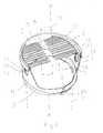
- FIG 1the chopping aid device is shown mounted on top of a chopping block 10 drawn with broken line.
- the chopping aid devicehas been tightened around the chopping block with a buckle or straining strap 9.
- the chopping aid devicelies with a bead 27 on the upper surface of the chopping block 10.
- the bead 27prevents wood debris from being accumulated in possible gaps between the chopping block 10 and the chopping aid device. It is, however, possible to lower the chopping aid device from the position shown in Figure 1 to a position where the bead 27 encircles the chopping block 10 by first moving it downwards in the vertical direction and thereafter tightening the straining strap 9 using the tightening and locking device 14 of the straining strap.
- Such loweringmay be desirable in order to provide good support for very short logs to be chopped. For reasons of simplicity, in the figure only one wood 11 to be chopped has been drafted.
- the woodsare placed vertically within the chopping aid device.
- a plurality of flexible spikes 3support the wood 11 to be chopped.
- the spikeshave a diameter of e.g. 1 to 2 mm, but the diameter can vary much depending on the material of the spikes, the size of the logs to be split, etc. If very thin spikes 3 are used (diameter 1 mm or less), the spikes can be called bristles.
- the spikes 3 adjacent the woodbend downwards thus providing a lateral force on the wood. By bending downwards, the risk of cutting or damaging in another way the spikes with an axe, is also reduced.
- the lateral force of the spikes 3supports the wood and ensures that the wood 11 is positively kept upright within the chopping aid device even if the cross-section of the wood supporting the wood from below does not, as such, provide adequate support owing to the reason that it is not at right angles to the longitudinal axis of the wood. Thanks to the spikes 3, the wood 11 is positively kept upright before it is hit with an axe (not shown) and also after it has been split with the axe. The next hit with the axe can immediately be carried out without an intermediate need to touch the wood.
- the chopping aid devicecomprises a basket-like cylindrical cuff frame 1 made of flexible elastomeric material, e.g. rubber, Thermo Plastic Elastomer (TPE), Polypropylene (PP) or Polyethylene (PE).
- the bottom 5 of the cuff frame 1is arranged around the upper end of the chopping block 10.
- the cuff frame 1is circumferentially open having a peripheral wall 26 which is non-continuous by comprising a slot 8 at the front side or user side.
- the slot 8enables to easily adjust the diameter of the bottom of the cuff frame 1 making it easy to position the cuff frame around chopping blocks 10 of different size.
- the diameter of the cuff frame 1is preferably about 400 mm. Such a cuff frame can easily be fastened to chopping blocks 10 having diameters between 300 to 500 mm.
- a cylindrical collar 7has been mounted on top of the cuff frame 1.
- the collar 7is made of a harder material than the cuff frame 1, e.g. from polyamide (nailon) Glassfiber reinforced Polyamide (PA) or Glassfiber reinforced Polybutylene terephthalate (PBT).
- PAPolyamide
- PBTGlassfiber reinforced Polybutylene terephthalate
- FIG 2shows the components of the chopping aid device of Figure 1 .
- the devicecomprises a cylindrical collar 7 to be mounted on top of the cuff frame 1.
- the spikes 3are detachably attached to the collar 7 in order to make replacement of worn and damaged spikes easy.
- the spikes 3are indirectly, by means of the collar 7 fastened to the cuff frame 1.
- the spikes 3 and the collar 7together form a support 2 to keep the wood 11 to be chopped upright and also to keep the chopped firewood upright.
- the collar 7is made of flexible material.
- the spikes 3are horizontal with respect to the collar 7 and the cuff frame 1.
- the distance from the bottom 5 of the cuff frame 1 to the upper edge 4 of the framevaries in such a way that the distance L1 at the front side or user side of the chopping aid device is much smaller than the distance L2 at the rear side of the chopping aid device, or at any other direction which differs from the front side.
- the cuff frame 1is open at the front side.
- the opening at the front side of the cuff frame 1gives space for the handle of the ax (not shown) when firewood is chopped and makes it easy to clean the upper surface of the chopping block 10 from wood debris.
- the distance L2is preferably about 200 mm.
- the distance L1can be e.g. 20 - 50 mm.
- the collar 7has a peripheral wall 12 which is non-continuous so that it comprises a peripheral opening 15.
- the opening 15 of the collar 7is aligned with the front side of the cuff frame 1.
- the opening 15(like the opening of the cuff frame 1) gives space for the handle of the axe when firewood is chopped.
- the collar 7is detachably fastened to the cuff frame 1.
- the upper edge 13 of the collar 7comprises a groove 16 to receive the upper edge 4 of the cuff frame 1.
- the height L3 of the collar 7must be less than the height L2 of the cuff frame 1 because the collar 7 must not hit the upper end of the chopping block 10 if the axe accidentally hits on the collar. If the distance L2, i.e. the maximum height of the cuff frame 1 is about 200 mm, the height L3 of the collar 7 is preferably 150 - 180 mm. In normal use of the chopping aid device, the collar 7 is fastened to the cuff frame 1 in such a way that the opening 15 thereof faces the user, c.f. Figure 1 .
- the collar 7can alternatively be positioned on the cuff frame 1 in such a way that the opening 15 thereof is diametrically opposite to the opening of the cuff frame 1.
- Such a positioning of the collar 7gives as result a chopping aid device having fully closed walls and no opening facing the user. Fully closed walls and detached spikes 3 allow to easily fill up the whole cross-section of the chopping aid device with woods.
- the collar 7can be rotated 0 to 180 degrees with respect to the cuff frame 1, it can be positioned on top of the cuff frame 1 so that the opening 15 thereof points at any desired direction.
- the spikes 3have been fastened at two arcs 17, 18 which, in turn, are detachably fastened to the collar 7, e.g. by snap-fasteners, which can be of pin-hole type.
- the spikes 3are directed horizontally to a longitudinal axis X - X of the cuff frame1.
- the spikes 3are fastened at opposite sides of the collar 7 so that two rows of spikes 3 are formed.
- the spikes 3 of one roware directed against the spikes 3 in the other row leaving between the free ends, i.e. between the tips of the spikes of respective row, a narrow slot-like zone 6 which is free of spikes.
- the width of the zone 6, against which the free ends of the spikes 3 are directed,is 10 to 50 mm.
- the zone 6is directed against the user and the spikes 3 are at right angles to the user.
- the spikes 3effectively prevent the wood from moving against the user when the wood is chopped and they also prevent the wood from collapsing within the cuff frame 1. Also, the spikes 3 are short enough (shorter than the height of the chopping aid device) so that the tips thereof do not reach the upper surface of the chopping block 10 when they are bent downwards.
- the spikescannot be cut by being pinched between the axe and the upper surface of the chopping block 10
- the angle of the spikes 3 in relation axis X - X and to the front side of the chopping aid device, and the user,does not have to be a right angle; however, an obtuse angle with respect to the front-rear-line of the chopping aid device is preferred.
- the chopping aid deviceTo make the chopping aid device easier to manufacture and also to avoid charging of logs too close to the margins of the chopping aid device, in which case the risk of mishits including hits on the edge of the chopping aid device increases, there is also at the rear side of the chopping aid device a segment 19 free of spikes as seen from Figure 1 .
- the front side of the chopping aid devicehas a similar segment (however, not shown by reference numeral) free of spikes.
- the spikes 3cover at least 70 % of the cross-sectional area of the cuff frame 1. In said figure of 70 % not only the total projection area of the individual spikes 3 but also the areas of the gaps between adjacent spikes are included.
- the chopping aid devicecomprises handles 20, 21 in order to make it easy to lift and move.
- the handles 20, 21are formed of holes 22, 23 and 24, 25 made in the cuff frame 1 and collar 7, respectively.
- the holes 22 and 23, like the holes 24 and 25are preferably spaced 180 degrees apart.
- the holes 23 to 25are not, however, indispensable as the chopping aid device is not heavy.
- Figure 3shows another embodiment of the chopping aid device.
- FIG 3has been used similar reference numerals as in Figure 1 for corresponding components.
- the embodiment of Figure 3differs from the embodiment of Figure 1 in that the spikes 3' are arranged in four levels 3a', 3b', 3c', 3d'.
- the length of the spikes 3' in the different levels 3a', 3b', 3c', 3d'diminishes in the direction downwards so that the average length of the spikes in a lower level, e.g. level 3c', is shorter than the average length of the spikes in an upper level, 3b' or 3a'.
- Such an arrangement of the spikes 3'has the advantage that it provides better support for the woods to be chopped by adding more progressive support force when more wood is added and prevents the creeping and permanent deflection of longer spikes by supporting them from underneath with shorter spikes which are less prone to creepage and deflection caused by gravity.
- the embodiment of Figure 3differs from the embodiment of Figure 1 further in that the spikes 3' are fastened to arcs in the form of holders 17', 18' which are fastened to the collar 7' by means of grooves 17a', 18a'.
- the holders 17', 18'also comprise branches 17b', 18b' the lower edge of which press against the cuff frame 1 and the collar 7.
- Figure 4which shows the holder 18' separately from the support 2', the groove 18a' is clearly seen.
- the groove 18a'receives the upper edge 13' of the collar 7'.
- the advantage of the groove 18a'is that the holder 18' is easy to position in place on the collar 7' and remove from the collar 7'.
- the holders 17', 18' of the embodiment of Figure 3also make it very easy to position the spikes 3 of two holders 17', 18' in such a way that the spikes 3' are in line regardless variations in diameter of the chopping block.
- the frame of the chopping aid deviceis not a basket-like cuff frame but a frame which is formed of e.g. two oppositely positioned walls and having two major openings between the walls.
- the cuff framecan have a geometrical form which is not cylindrical: the cross-section of the device can be elliptic or square.
- a cylindrical formis preferable, because a cylindrical cuff frame is easy to position on top of a chopping block.
- the bead in the inner wall of the cuff frame 1is not indispensable, but is highly preferable, because it gives stability to the chopping aid device.
- the chopping aid devicecan be used without an ordinary chopping block: it can be positioned on a firm base which provides the required support for chopping woods. In such a situation the cross-section of the chopping aid device can very well be for instance rectangular, in which case no straining strap is needed.
- the zone 6 in the central area of the cross-section of the cuff frame 1need not have the form of a slot; it can e.g. have the form of a circle or some other form.
- the chopping aid deviceby integrating the support (c.f. support 2, 2') with the cuff frame (c.f. cuff frame 1, 1').
- Thiscan e.g. be carried out by two component molding.
- the supportis injection molded of a material providing a support durable against cuts
- the cuff frameis, in the same injection molding machine, injection molded of a material providing a cuff frame which is flexible and resilient.
Landscapes
- Life Sciences & Earth Sciences (AREA)
- Engineering & Computer Science (AREA)
- Wood Science & Technology (AREA)
- Forests & Forestry (AREA)
- Food-Manufacturing Devices (AREA)
- Harvester Elements (AREA)
- Solid Fuels And Fuel-Associated Substances (AREA)
Abstract
Description
- The invention relates to a chopping aid device for use in chopping of firewood, the chopping aid device comprising a frame to prevent pieces of wood to spread into the surroundings outside the chopping aid device during chopping.
- Such a chopping aid device is known from patent publication
EP 1886779 B1 . This known device in the form of a basket-like closed ring frame is designed to be mounted onto a chopping block and designed to prevent chopped wood to fall to the ground from the chopping block. By having this function, the chopping aid device provides at the same time for the user, and for people nearby the chopping aid device, safety in that chopped wood does not fly and hit the user or the people nearby. However, if the basket-like frame is not filled enough with chopping woods, the risk remains that the chopped wood flies over the ring frame. Further, the logs will easily turn to a position not being upright as a result of an incorrect hit with the axe. Still further, there is a risk of the axe bouncing pass the chopping block and hitting on the ground or on the knee/leg/foot of the person who is chopping. - Woods to be chopped shall be placed upright on the chopping block. This is not always easy. Especially if the wood to be chopped has a cut surface which is at an oblique angle in relation to the longitudinal axis of the wood to be chopped, the wood cannot be placed on the chopping block so that it remains upright without support. This problem, also present with the known chopping aid device of
EP 1886779 B1 , can be - provided the chopping block has an even planar upper surface and is not worn - solved by cutting off the inclined surface from the wood to be chopped and replacing the inclined surface with a surface which is perpendicular to the longitudinal axis of the wood to be chopped. Such a procedure is, however, time consuming and creates wood debris. Neither does it give the desired result if the chopping block has worn so that the upper surface thereof shows a concave form. Sometimes the problem with an oblique support area is solved by keeping the wood by hand in upright position and taking quickly the hand off the wood before hitting the wood with the axe. The wood must be hit immediately after the hand has been taken off the wood, because otherwise the wood turns horizontal making the chopping impossible. Such chopping is dangerous, difficult and time consuming. If the hand is not taken off the wood, there is an imminent possibility for injury. If the wood to be chopped is not split with one hit and the ring frame has not been fully filled with woods to be chopped, the wood will typically move within the ring frame in such a position that one must correct its position to enable a successful next hit with the axe. This is time consuming. - An object of the invention is to provide a new chopping aid device, to be used for chopping firewood, which device generally makes chopping and splitting of logs easier, faster and safer. Justifiably the device could also be called a safety device.
- The chopping aid device of the invention is characterized by a support comprising a plurality of flexible spikes to keep the firewood in an upright position within the cuff frame.
- An essential idea of the invention is to use a plurality of flexible spikes, or the like, to keep the wood to be chopped upright within the frame of the device, the spikes (or the like) being adapted to support the wood laterally from its periphery and to keep the wood in place within the frame of the device. With the term "spike" is meant any type of longitudinal element, e.g. bristles providing the desired function.
- Preferably the frame is a basket-like cuff frame comprising an upper edge whose distance from the bottom of the cuff frame is smaller at the front side or user side than the distance from the bottom at a side which differs from the front side. This prevents the handle of the axe from hitting the cuff frame when chopping.
- Preferably the first ends of the spikes which are opposite to free ends of the spikes are attached to the cuff frame, whereby the spikes preferably are directed at least substantially horizontal within the cuff frame and preferably at an obtuse angle with respect a front-rear-line of the chopping aid device. Such arrangement of the spikes provides a good support for the woods and positively keeps the woods within the cuff frame. In such an arrangement
- preferably further the cuff frame is flexible and made of elastomeric material and the collar is made of harder material than the cuff frame. Such a selection of materials makes the chopping aid device durable: the collar prevents the blade of the axe to cut into the cuff frame, and the cuff frame prevents, by providing dampening properties, the collar from being damaged by the impact of the axe.
- Preferably the spikes are detachably fastened to the collar. This makes replacement of worn or broken spikes easy.
- In order to very effectively support plenty of woods, i.e. within the major area of the cuff frame, the spikes cover at least 70 % of the cross-sectional area of the cuff frame.
- Preferred embodiments of the chopping aid device according to the invention are disclosed in the attached claims.
- The most important advantages of the chopping aid device according to the invention are that it makes chopping of wood easy, fast and safe. The chopping aid device allows to keep all sizes and shapes of woods upright all the time for more continuous splitting. The chopping aid device avoids the need for constant and cumbersome resetting of woods. Several woods or, if desired, only one wood, can be put into the chopping aid device at a time. The chopping aid device collects small debris from cutting making the splitting work less strenuous. The chopping aid device prevents the axe from bouncing astray during splitting and prevents woods from flying away.
- In the following the invention will be described in closer detail by means of two embodiments and with reference to the accompanying drawing in which:
Figure 1 shows the first embodiment of the chopping aid device mounted on a chopping block,Figure 2 shows the chopping aid device ofFigure 1 in an exploded view,Figure 3 shows the second embodiment of the chopping aid device, andFigure 4 shows a detail of the chopping aid device ofFigure 3 .- In
Figure 1 the chopping aid device is shown mounted on top of achopping block 10 drawn with broken line. The chopping aid device has been tightened around the chopping block with a buckle or strainingstrap 9. The chopping aid device lies with abead 27 on the upper surface of thechopping block 10. Thebead 27 prevents wood debris from being accumulated in possible gaps between thechopping block 10 and the chopping aid device. It is, however, possible to lower the chopping aid device from the position shown inFigure 1 to a position where thebead 27 encircles thechopping block 10 by first moving it downwards in the vertical direction and thereafter tightening the strainingstrap 9 using the tightening andlocking device 14 of the straining strap. Such lowering may be desirable in order to provide good support for very short logs to be chopped. For reasons of simplicity, in the figure only one wood 11 to be chopped has been drafted. - As illustrated in
Figure 1 , the woods are placed vertically within the chopping aid device. A plurality offlexible spikes 3 support the wood 11 to be chopped. The spikes have a diameter of e.g. 1 to 2 mm, but the diameter can vary much depending on the material of the spikes, the size of the logs to be split, etc. If verythin spikes 3 are used (diameter 1 mm or less), the spikes can be called bristles. When the wood 11 is positioned within the chopping aid device, thespikes 3 adjacent the wood bend downwards thus providing a lateral force on the wood. By bending downwards, the risk of cutting or damaging in another way the spikes with an axe, is also reduced. The lateral force of thespikes 3 supports the wood and ensures that the wood 11 is positively kept upright within the chopping aid device even if the cross-section of the wood supporting the wood from below does not, as such, provide adequate support owing to the reason that it is not at right angles to the longitudinal axis of the wood. Thanks to thespikes 3, the wood 11 is positively kept upright before it is hit with an axe (not shown) and also after it has been split with the axe. The next hit with the axe can immediately be carried out without an intermediate need to touch the wood. - The chopping aid device comprises a basket-like cylindrical cuff frame 1 made of flexible elastomeric material, e.g. rubber, Thermo Plastic Elastomer (TPE), Polypropylene (PP) or Polyethylene (PE). The bottom 5 of the cuff frame 1 is arranged around the upper end of the
chopping block 10. The cuff frame 1 is circumferentially open having aperipheral wall 26 which is non-continuous by comprising a slot 8 at the front side or user side. The slot 8 enables to easily adjust the diameter of the bottom of the cuff frame 1 making it easy to position the cuff frame aroundchopping blocks 10 of different size. By tightening the strainingstrap 9, the cuff frame 1 will steadily be fastened to thechopping block 10. The diameter of the cuff frame 1 is preferably about 400 mm. Such a cuff frame can easily be fastened tochopping blocks 10 having diameters between 300 to 500 mm. - Because the cuff frame 1 is resilient, it will dampen the impact on the chopping aid device if the device is accidentally hit on by the axe. To protect the cuff frame 1 form being damaged by an accidental hit, a
cylindrical collar 7 has been mounted on top of the cuff frame 1. Thecollar 7 is made of a harder material than the cuff frame 1, e.g. from polyamide (nailon) Glassfiber reinforced Polyamide (PA) or Glassfiber reinforced Polybutylene terephthalate (PBT). Thecollar 7 distributes the force of the accidental hit to a large area of the cuff frame 1 thus preventing the blade of the axe to cut into the cuff frame 1. Even a relatively strong hit on thecollar 7 will not damage the collar, because the cuff frame 1 under the collar dampens effectively the hit. Figure 2 shows the components of the chopping aid device ofFigure 1 . The device comprises acylindrical collar 7 to be mounted on top of the cuff frame 1. Thespikes 3 are detachably attached to thecollar 7 in order to make replacement of worn and damaged spikes easy. Thus thespikes 3 are indirectly, by means of thecollar 7 fastened to the cuff frame 1. Thespikes 3 and thecollar 7 together form asupport 2 to keep the wood 11 to be chopped upright and also to keep the chopped firewood upright. Thecollar 7 is made of flexible material. Thespikes 3 are horizontal with respect to thecollar 7 and the cuff frame 1.- The distance from the bottom 5 of the cuff frame 1 to the upper edge 4 of the frame varies in such a way that the distance L1 at the front side or user side of the chopping aid device is much smaller than the distance L2 at the rear side of the chopping aid device, or at any other direction which differs from the front side. In this way the cuff frame 1 is open at the front side. The opening at the front side of the cuff frame 1 gives space for the handle of the ax (not shown) when firewood is chopped and makes it easy to clean the upper surface of the
chopping block 10 from wood debris. The distance L2 is preferably about 200 mm. The distance L1 can be e.g. 20 - 50 mm. - The
collar 7 has aperipheral wall 12 which is non-continuous so that it comprises aperipheral opening 15. When thecollar 7 is put on top of the cuff frame 1, theopening 15 of thecollar 7 is aligned with the front side of the cuff frame 1. The opening 15 (like the opening of the cuff frame 1) gives space for the handle of the axe when firewood is chopped. - The
collar 7 is detachably fastened to the cuff frame 1. For this purpose theupper edge 13 of thecollar 7 comprises agroove 16 to receive the upper edge 4 of the cuff frame 1. The height L3 of thecollar 7 must be less than the height L2 of the cuff frame 1 because thecollar 7 must not hit the upper end of thechopping block 10 if the axe accidentally hits on the collar. If the distance L2, i.e. the maximum height of the cuff frame 1 is about 200 mm, the height L3 of thecollar 7 is preferably 150 - 180 mm. In normal use of the chopping aid device, thecollar 7 is fastened to the cuff frame 1 in such a way that theopening 15 thereof faces the user, c.f.Figure 1 . However, thecollar 7 can alternatively be positioned on the cuff frame 1 in such a way that theopening 15 thereof is diametrically opposite to the opening of the cuff frame 1. Such a positioning of thecollar 7 gives as result a chopping aid device having fully closed walls and no opening facing the user. Fully closed walls anddetached spikes 3 allow to easily fill up the whole cross-section of the chopping aid device with woods. Because thecollar 7 can be rotated 0 to 180 degrees with respect to the cuff frame 1, it can be positioned on top of the cuff frame 1 so that theopening 15 thereof points at any desired direction. - The
spikes 3 have been fastened at twoarcs collar 7, e.g. by snap-fasteners, which can be of pin-hole type. - As can be seen from
Figures 1 and2 , thespikes 3 are directed horizontally to a longitudinal axis X - X of the cuff frame1. Thespikes 3 are fastened at opposite sides of thecollar 7 so that two rows ofspikes 3 are formed. Thespikes 3 of one row are directed against thespikes 3 in the other row leaving between the free ends, i.e. between the tips of the spikes of respective row, a narrow slot-like zone 6 which is free of spikes. The width of the zone 6, against which the free ends of thespikes 3 are directed, is 10 to 50 mm. The zone 6 is directed against the user and thespikes 3 are at right angles to the user. - Thanks to said arrangement of the
spikes 3, thespikes 3 effectively prevent the wood from moving against the user when the wood is chopped and they also prevent the wood from collapsing within the cuff frame 1. Also, thespikes 3 are short enough (shorter than the height of the chopping aid device) so that the tips thereof do not reach the upper surface of thechopping block 10 when they are bent downwards. Owing to this, the spikes cannot be cut by being pinched between the axe and the upper surface of thechopping block 10 The angle of thespikes 3 in relation axis X - X and to the front side of the chopping aid device, and the user, does not have to be a right angle; however, an obtuse angle with respect to the front-rear-line of the chopping aid device is preferred. - To make the chopping aid device easier to manufacture and also to avoid charging of logs too close to the margins of the chopping aid device, in which case the risk of mishits including hits on the edge of the chopping aid device increases, there is also at the rear side of the chopping aid device a segment 19 free of spikes as seen from
Figure 1 . The front side of the chopping aid device has a similar segment (however, not shown by reference numeral) free of spikes. Thespikes 3 cover at least 70 % of the cross-sectional area of the cuff frame 1. In said figure of 70 % not only the total projection area of theindividual spikes 3 but also the areas of the gaps between adjacent spikes are included. - The chopping aid device comprises
handles handles holes collar 7, respectively. Theholes 22 and 23, like theholes Figure 3 shows another embodiment of the chopping aid device. InFigure 3 has been used similar reference numerals as inFigure 1 for corresponding components. For the sake of simplicity only one spike 3' has been separately drafted inFigure 3 although the number of spikes in the support 2' is large, like in the embodiment ofFigure 1 .- The embodiment of
Figure 3 differs from the embodiment ofFigure 1 in that the spikes 3' are arranged in four levels 3a', 3b', 3c', 3d'. The length of the spikes 3' in the different levels 3a', 3b', 3c', 3d' diminishes in the direction downwards so that the average length of the spikes in a lower level, e.g. level 3c', is shorter than the average length of the spikes in an upper level, 3b' or 3a'. Such an arrangement of the spikes 3' has the advantage that it provides better support for the woods to be chopped by adding more progressive support force when more wood is added and prevents the creeping and permanent deflection of longer spikes by supporting them from underneath with shorter spikes which are less prone to creepage and deflection caused by gravity. - The embodiment of
Figure 3 differs from the embodiment ofFigure 1 further in that the spikes 3' are fastened to arcs in the form of holders 17', 18' which are fastened to the collar 7' by means of grooves 17a', 18a'. The holders 17', 18' also comprise branches 17b', 18b' the lower edge of which press against the cuff frame 1 and thecollar 7. FromFigure 4 , which shows the holder 18' separately from the support 2', thegroove 18a' is clearly seen. InFigure 3 thegroove 18a' receives the upper edge 13' of the collar 7'. The advantage of thegroove 18a' is that the holder 18' is easy to position in place on the collar 7' and remove from the collar 7'. The holders 17', 18' of the embodiment ofFigure 3 also make it very easy to position thespikes 3 of two holders 17', 18' in such a way that the spikes 3' are in line regardless variations in diameter of the chopping block. - Still further the embodiment of
Figure 3 differs from the embodiment ofFigure 1 in that the width of the zone 6' free of spikes is negligible small. - The invention has been described above only by two examples. It shall be understood that the invention can be implemented in many ways within the scope of the attached claims. Hence, it is for instance possible that the frame of the chopping aid device is not a basket-like cuff frame but a frame which is formed of e.g. two oppositely positioned walls and having two major openings between the walls. If a basket-like cuff frame is used, the cuff frame can have a geometrical form which is not cylindrical: the cross-section of the device can be elliptic or square. However, a cylindrical form is preferable, because a cylindrical cuff frame is easy to position on top of a chopping block. The bead in the inner wall of the cuff frame 1 is not indispensable, but is highly preferable, because it gives stability to the chopping aid device. The chopping aid device, however, can be used without an ordinary chopping block: it can be positioned on a firm base which provides the required support for chopping woods. In such a situation the cross-section of the chopping aid device can very well be for instance rectangular, in which case no straining strap is needed. The zone 6 in the central area of the cross-section of the cuff frame 1 need not have the form of a slot; it can e.g. have the form of a circle or some other form. Further, deviating from what has been disclosed in the two embodiments, it is possible to implement the chopping aid device by integrating the support (c.f.
support 2, 2') with the cuff frame (c.f. cuff frame 1, 1'). This can e.g. be carried out by two component molding. The support is injection molded of a material providing a support durable against cuts, and the cuff frame is, in the same injection molding machine, injection molded of a material providing a cuff frame which is flexible and resilient.
Claims (20)
- A chopping aid device for use in chopping of firewood, the chopping device comprising a frame (1, 1') to prevent pieces of wood to spread into the surroundings outside the chopping aid device during chopping,characterized by a support (2, 2') comprising a plurality of flexible spikes (3, 3') to keep the firewood in an upright position within the frame (1, 1').
- A chopping aid device according to claim 1,characterized in that the frame (1, 1') is a basket-like cuff frame.
- A chopping aid device according to claim 1,characterized in that the frame comprises an upper edge (4, 4') whose distance (L1) from a bottom (5, 5') of the frame is smaller at the front side or user side than the distance (L2) from the bottom at a side which differs from the front side.
- A chopping aid device according to one of claims 1 to 3,char-acterized in that the frame is open at the front side or user side.
- A chopping aid device according to claim 4,characterized in that the frame is circumferentially open having a peripheral wall (26, 26') which is non-continuous by comprising a slot (8, 8') is at the front side.
- A chopping aid device according to any one of the preceding claims,characterized in that first ends of the spikes (3, 3') which are opposite to free ends of the spikes are attached to the support (2, 2').
- A chopping aid device according to any one of the preceding claims 1 to 6,characterized in that the first ends of the spikes (3, 3') are fastened to a collar (7, 7') which is circumferentially open having a peripheral wall (12, 12') which is non-continuous having a peripheral opening (15, 15'), and which collar is detachably fastened to the frame so that the peripheral opening (15, 15') is aligned with the front side of the frame.
- A chopping aid device according to claim 7,characterized in that the spikes (3, 3') are detachably fastened to the collar (7, 7').
- A chopping aid device according to claim 8,characterized in that the spikes (3') are detachably fastened to the collar (7') via a holder (17', 18') having a groove (17a', 18a') for receiving an upper edge (13') of the collar (7').
- A chopping aid device according to any one of the preceding claims 7 to 9,characterized in that the frame is cylindrical andin that the collar (7, 7') is cylindrical.
- A chopping aid device according to claim 10,characterized in that the lower region of the inner wall of the frame comprises a circular bead (27, 27').
- A chopping aid device according to claim 10 or 11,characterized in that the collar (7, 7') is rotatable with respect to the frame.
- A chopping aid device according to any one on the preceding claims 7 to 12,characterized in that the frame is flexible and made of elastomeric material andin that the collar (7, 7') is made of harder material than the frame.
- A chopping aid device according to any one of the preceding claims 2 to 13,characterized by a straining strap (9, 9') attached to a bottom (5, 5') of the frame for adjusting the diameter of the bottom (5, 5') of the frame.
- A chopping aid device according to any one of the preceding claims,characterized in that the spikes (3, 3') are directed at least substantially horizontal within the frame (1, 1') being at least substantially at right angles to a longitudinal axis (X - X) of the frame (1, 1').
- A chopping aid device according to any one on the preceding claims 2 to 15,characterized in that at least the greater part of the cross-sectional area of the frame is covered by the spikes (3, 3') of the support (2, 2').
- A chopping aid device according to any one of the preceding claims,characterized in that the spikes (3, 3') are directed at an obtuse angle with respect to a front-rear-line of the chopping aid device.
- A chopping aid device according to any one of the preceding claims 2 to 17,characterized in that a cross-sectional area of the frame is free of spikes (3, 3') at an area which is at the front side of the frame.
- A chopping aid device according to claim 18,characterized in that the cross-sectional area is a segment.
- A chopping aid device according to claim 1,characterized in that the support (2') comprises spikes (3') arranged in a plurality of levels (3a', 3b', 3c', 3d') in which the length of the spikes in a lower level (3b') is shorter than the length of the spikes in an upper level (3a').
Priority Applications (1)
| Application Number | Priority Date | Filing Date | Title |
|---|---|---|---|
| PL13197593TPL2746010T3 (en) | 2012-12-20 | 2013-12-17 | Chopping aid device for use in chopping of firewood |
Applications Claiming Priority (1)
| Application Number | Priority Date | Filing Date | Title |
|---|---|---|---|
| FI20126351AFI125227B (en) | 2012-12-20 | 2012-12-20 | Device for facilitating cleavage for use in firewood cleavage |
Publications (2)
| Publication Number | Publication Date |
|---|---|
| EP2746010A1true EP2746010A1 (en) | 2014-06-25 |
| EP2746010B1 EP2746010B1 (en) | 2015-07-08 |
Family
ID=49911192
Family Applications (1)
| Application Number | Title | Priority Date | Filing Date |
|---|---|---|---|
| EP13197593.0ANot-in-forceEP2746010B1 (en) | 2012-12-20 | 2013-12-17 | Chopping aid device for use in chopping of firewood |
Country Status (8)
| Country | Link |
|---|---|
| US (1) | US9333671B2 (en) |
| EP (1) | EP2746010B1 (en) |
| CN (1) | CN103878851B (en) |
| CA (1) | CA2837424C (en) |
| DK (1) | DK2746010T3 (en) |
| FI (1) | FI125227B (en) |
| PL (1) | PL2746010T3 (en) |
| RU (1) | RU2637214C2 (en) |
Cited By (1)
| Publication number | Priority date | Publication date | Assignee | Title |
|---|---|---|---|---|
| WO2017042425A1 (en)* | 2015-09-09 | 2017-03-16 | Serlachius Jarl Fredik | Wood chopping base |
Families Citing this family (47)
| Publication number | Priority date | Publication date | Assignee | Title |
|---|---|---|---|---|
| US6676127B2 (en) | 1997-03-13 | 2004-01-13 | Shuffle Master, Inc. | Collating and sorting apparatus |
| US6655684B2 (en) | 1998-04-15 | 2003-12-02 | Shuffle Master, Inc. | Device and method for forming and delivering hands from randomly arranged decks of playing cards |
| US6254096B1 (en) | 1998-04-15 | 2001-07-03 | Shuffle Master, Inc. | Device and method for continuously shuffling cards |
| US8590896B2 (en) | 2000-04-12 | 2013-11-26 | Shuffle Master Gmbh & Co Kg | Card-handling devices and systems |
| US8337296B2 (en) | 2001-09-28 | 2012-12-25 | SHFL entertaiment, Inc. | Method and apparatus for using upstream communication in a card shuffler |
| US7677565B2 (en) | 2001-09-28 | 2010-03-16 | Shuffle Master, Inc | Card shuffler with card rank and value reading capability |
| US7753373B2 (en) | 2001-09-28 | 2010-07-13 | Shuffle Master, Inc. | Multiple mode card shuffler and card reading device |
| US8011661B2 (en) | 2001-09-28 | 2011-09-06 | Shuffle Master, Inc. | Shuffler with shuffling completion indicator |
| US8616552B2 (en) | 2001-09-28 | 2013-12-31 | Shfl Entertainment, Inc. | Methods and apparatuses for an automatic card handling device and communication networks including same |
| US6886829B2 (en) | 2002-02-08 | 2005-05-03 | Vendingdata Corporation | Image capturing card shuffler |
| US20060066048A1 (en) | 2004-09-14 | 2006-03-30 | Shuffle Master, Inc. | Magnetic jam detection in a card shuffler |
| US7764836B2 (en) | 2005-06-13 | 2010-07-27 | Shuffle Master, Inc. | Card shuffler with card rank and value reading capability using CMOS sensor |
| US7556266B2 (en) | 2006-03-24 | 2009-07-07 | Shuffle Master Gmbh & Co Kg | Card shuffler with gravity feed system for playing cards |
| US8342525B2 (en) | 2006-07-05 | 2013-01-01 | Shfl Entertainment, Inc. | Card shuffler with adjacent card infeed and card output compartments |
| US8353513B2 (en) | 2006-05-31 | 2013-01-15 | Shfl Entertainment, Inc. | Card weight for gravity feed input for playing card shuffler |
| US8579289B2 (en) | 2006-05-31 | 2013-11-12 | Shfl Entertainment, Inc. | Automatic system and methods for accurate card handling |
| US8070574B2 (en) | 2007-06-06 | 2011-12-06 | Shuffle Master, Inc. | Apparatus, system, method, and computer-readable medium for casino card handling with multiple hand recall feature |
| US8919775B2 (en) | 2006-11-10 | 2014-12-30 | Bally Gaming, Inc. | System for billing usage of an automatic card handling device |
| US8967621B2 (en) | 2009-04-07 | 2015-03-03 | Bally Gaming, Inc. | Card shuffling apparatuses and related methods |
| US7988152B2 (en) | 2009-04-07 | 2011-08-02 | Shuffle Master, Inc. | Playing card shuffler |
| US8800993B2 (en) | 2010-10-14 | 2014-08-12 | Shuffle Master Gmbh & Co Kg | Card handling systems, devices for use in card handling systems and related methods |
| US8485527B2 (en) | 2011-07-29 | 2013-07-16 | Savant Shuffler LLC | Card shuffler |
| US9731190B2 (en) | 2011-07-29 | 2017-08-15 | Bally Gaming, Inc. | Method and apparatus for shuffling and handling cards |
| US8960674B2 (en) | 2012-07-27 | 2015-02-24 | Bally Gaming, Inc. | Batch card shuffling apparatuses including multi-card storage compartments, and related methods |
| US9511274B2 (en) | 2012-09-28 | 2016-12-06 | Bally Gaming Inc. | Methods for automatically generating a card deck library and master images for a deck of cards, and a related card processing apparatus |
| US9378766B2 (en) | 2012-09-28 | 2016-06-28 | Bally Gaming, Inc. | Card recognition system, card handling device, and method for tuning a card handling device |
| FI20126350A7 (en)* | 2012-12-20 | 2014-06-21 | Fiskars Brands Finland Oy Ab | Chopping aid device for use in chopping of firewood |
| EP3263193B1 (en) | 2014-04-11 | 2019-06-05 | Bally Gaming, Inc. | Method and apparatus for shuffling and handling cards |
| EP2942168B1 (en) | 2014-05-09 | 2018-02-07 | Fiskars Finland Oy Ab | Chopping aid |
| US9474957B2 (en) | 2014-05-15 | 2016-10-25 | Bally Gaming, Inc. | Playing card handling devices, systems, and methods for verifying sets of cards |
| US9566501B2 (en) | 2014-08-01 | 2017-02-14 | Bally Gaming, Inc. | Hand-forming card shuffling apparatuses including multi-card storage compartments, and related methods |
| USD764599S1 (en) | 2014-08-01 | 2016-08-23 | Bally Gaming, Inc. | Card shuffler device |
| US9504905B2 (en) | 2014-09-19 | 2016-11-29 | Bally Gaming, Inc. | Card shuffling device and calibration method |
| CN104441170B (en)* | 2014-11-11 | 2016-10-26 | 倪晖 | A kind of fixture for plank of riving |
| CN104354204B (en)* | 2014-11-11 | 2016-04-13 | 刘闻宇 | A kind of firewood fixture |
| CN104665653A (en)* | 2015-03-17 | 2015-06-03 | 余戈平 | Chopping board |
| US9993719B2 (en) | 2015-12-04 | 2018-06-12 | Shuffle Master Gmbh & Co Kg | Card handling devices and related assemblies and components |
| US10339765B2 (en) | 2016-09-26 | 2019-07-02 | Shuffle Master Gmbh & Co Kg | Devices, systems, and related methods for real-time monitoring and display of related data for casino gaming devices |
| US10933300B2 (en) | 2016-09-26 | 2021-03-02 | Shuffle Master Gmbh & Co Kg | Card handling devices and related assemblies and components |
| US11376489B2 (en) | 2018-09-14 | 2022-07-05 | Sg Gaming, Inc. | Card-handling devices and related methods, assemblies, and components |
| WO2020055886A1 (en) | 2018-09-14 | 2020-03-19 | Sg Gaming, Inc. | Card-handling devices and related methods, assemblies, and components |
| US11896891B2 (en) | 2018-09-14 | 2024-02-13 | Sg Gaming, Inc. | Card-handling devices and related methods, assemblies, and components |
| US11338194B2 (en) | 2018-09-28 | 2022-05-24 | Sg Gaming, Inc. | Automatic card shufflers and related methods of automatic jam recovery |
| PH12020050309A1 (en) | 2019-09-10 | 2021-03-22 | Shuffle Master Gmbh And Co Kg | Card-handling devices with defect detection and related methods |
| US11173383B2 (en) | 2019-10-07 | 2021-11-16 | Sg Gaming, Inc. | Card-handling devices and related methods, assemblies, and components |
| US11883976B2 (en)* | 2020-01-23 | 2024-01-30 | Harold Allen | Wedge holder for log splitting |
| CN113001697B (en)* | 2021-03-24 | 2022-09-23 | 江苏艾威机械制造有限公司 | Agricultural wood chopping equipment |
Citations (11)
| Publication number | Priority date | Publication date | Assignee | Title |
|---|---|---|---|---|
| US4515195A (en)* | 1983-07-20 | 1985-05-07 | Harvey Gladstein | Method and apparatus for supporting logs and the like |
| US4535980A (en)* | 1983-12-21 | 1985-08-20 | Jordan Ross W | Log holder for use in splitting logs |
| CZ6499U1 (en)* | 1997-07-18 | 1997-09-04 | Miroslav Doc. Ing. Rajnoch | Block for wood splitting |
| DE202004011826U1 (en)* | 2004-07-28 | 2004-11-04 | Karsten, Dieter, Dipl.-Ing. | Device to ease chopping of wood consists of flat steel base with curved round bars welded to it, for fastening below edge of wood block to be cut |
| DE202004017096U1 (en)* | 2004-10-29 | 2005-03-24 | Metzler Stefan | Gripping ring for use with conventional chopping trunks has ring holding the wooden blocks to be chopped upright on the trunk and preventing them from springing off due to the force exerted when chopping |
| DE202005001959U1 (en)* | 2005-02-08 | 2005-05-12 | Schlappkohl Berlitz, Jens | Device for facilitating working with wood is rubber casing with expansion opening for split wood, for cleaning supporting surface attached to striking block; casing is attached horizontally to striking block by screws, attachment profile |
| DE102004063195A1 (en)* | 2004-12-29 | 2006-07-20 | Berlitz Jens Schlappkohl | Safety device for preventing accidents during wood splitting has a special rubber sleeve with an aperture fastened on a block of wood |
| EP1886779B1 (en) | 2006-08-12 | 2008-09-03 | Firepoint GmbH & Co. KG | Chopping block with a wood collection device |
| DE102008016470A1 (en)* | 2008-03-31 | 2009-10-01 | Hans-Peter Vollmer | Mechanical device for splitting wood, has four holding arms pressed apart by foot-operated mechanical lever for positioning wood, and pressed afterwards by spring traction against wood which is split |
| DE202009015866U1 (en)* | 2009-11-19 | 2010-04-08 | Müller, Hanno | Chipboard gap helpers |
| DE202011102982U1 (en)* | 2011-07-06 | 2011-10-19 | Franz Käsberger | Universal holding device for splitting firewood |
Family Cites Families (38)
| Publication number | Priority date | Publication date | Assignee | Title |
|---|---|---|---|---|
| US1309396A (en)* | 1919-07-08 | Planogkapii co | ||
| US1026721A (en)* | 1911-03-27 | 1912-05-21 | Us Slicing Machine Co | Meat-holder. |
| US1117412A (en)* | 1914-09-10 | 1914-11-17 | Patrick F Lynch | Ear-corn-holding device. |
| US1149525A (en)* | 1914-11-12 | 1915-08-10 | Alexander Kennedy | Slicing apparatus. |
| US1156510A (en)* | 1915-04-14 | 1915-10-12 | Edwin F Welz | Meat-holder. |
| US1203256A (en)* | 1915-10-21 | 1916-10-31 | George J Sayer | Meat-holding mechanism. |
| US1257587A (en)* | 1917-11-27 | 1918-02-26 | Us Slicing Machine Co | Work-holder for slicing-machines. |
| US1289848A (en)* | 1917-11-27 | 1918-12-31 | John B Mainville | Meat-holder. |
| US1468705A (en)* | 1918-04-08 | 1923-09-25 | A J Deer Company Inc | Article holder for slicing machines |
| US1418213A (en)* | 1921-06-20 | 1922-05-30 | Sviontek Roman | Meat holder |
| US1513853A (en)* | 1922-02-24 | 1924-11-04 | John H Osborne | Clamp for slicing machines |
| US1474296A (en)* | 1922-04-18 | 1923-11-13 | O H Bowden | Meat holder |
| US1558325A (en)* | 1923-08-24 | 1925-10-20 | Dayton Scale Co | Clamp for meat-slicing machines |
| US1748685A (en)* | 1927-11-28 | 1930-02-25 | Cincinnati Time Recorder Co | Meat clamp for slicing machines |
| US1823608A (en)* | 1928-12-05 | 1931-09-15 | James N Kalkanis | Holder for hams or the like |
| SU17726A1 (en)* | 1929-07-10 | 1930-09-30 | Г.Я. Федоров | Mobile drovokolny machine with a friction mechanism for the control of the ax |
| US2620003A (en)* | 1950-04-03 | 1952-12-02 | Jr Zack T Perdue | Base with meat carving facilities |
| US2688353A (en)* | 1951-10-20 | 1954-09-07 | Us Slicing Machine Co Inc | Needle bar assembly for meat clamps |
| US2751951A (en)* | 1953-12-31 | 1956-06-26 | Strathaus John | Roast board |
| US2953180A (en)* | 1958-06-04 | 1960-09-20 | William H Kyles | Melon holder |
| US3169760A (en) | 1962-10-26 | 1965-02-16 | Field Paul | Apparatus for facilitating splitting of cord wood and the like |
| US3386728A (en)* | 1965-03-11 | 1968-06-04 | Harry J. Smakel | Pin master |
| US4235428A (en)* | 1979-03-15 | 1980-11-25 | Davis Jack H | Bone transfixation pin guide |
| US4326703A (en)* | 1980-08-26 | 1982-04-27 | Marley William R | Cut log section holder for log splitting operation |
| SU1009765A1 (en)* | 1981-03-18 | 1983-04-07 | Дальневосточный научно-исследовательский институт лесной промышленности | Machine for disbarking timber,cutting head for splitting timber, pressing plate of moving mechanism disbarking mill, timber slewing mechanism and loading mechanism of disbarking machine |
| DE3202062C2 (en) | 1982-01-23 | 1983-12-01 | Dieter 2370 Rendsburg Kannenberg | Chopping block |
| US4468018A (en)* | 1982-07-28 | 1984-08-28 | Glanfield Lawrence (Concessions) Ltd. | Device for holding logs for sawing |
| RU2109622C1 (en)* | 1993-05-06 | 1998-04-27 | Василий Савельевич Сомов | Wood chopper and firewood chopping method |
| DE19703829A1 (en) | 1997-02-01 | 1998-08-06 | Hans Stockmann | Modified hydraulic wood-splitter with safety appliance |
| US7497327B2 (en) | 2005-08-02 | 2009-03-03 | National Gypsum Properties, Llc | Wallboard finishing system |
| US20080073361A1 (en) | 2006-09-25 | 2008-03-27 | Roger Brouard | Resilient container |
| CN200960688Y (en)* | 2006-10-30 | 2007-10-17 | 扬州和益电动工具有限公司 | Vertical wood splitting machine with automatic decompression mechanism |
| CN201098940Y (en)* | 2007-08-14 | 2008-08-13 | 杨卫平 | Vertical wood splitting machine |
| US7731074B2 (en) | 2008-10-14 | 2010-06-08 | Martin Joseph M | Portable, self-contained soldering system |
| CA2689312A1 (en) | 2008-12-30 | 2010-06-30 | Robert Maclean | Angled wood holder |
| US8678366B2 (en) | 2009-08-28 | 2014-03-25 | Jason Bowers | Portable cradle device |
| CN201505972U (en)* | 2009-10-20 | 2010-06-16 | 扬州神龙机械制造有限公司 | Vertical splitter provided with pump body shield |
| US8757421B2 (en) | 2011-02-14 | 2014-06-24 | Starbucks Corporation | Beverage packaging and method of manufacture |
- 2012
- 2012-12-20FIFI20126351Apatent/FI125227B/ennot_activeIP Right Cessation
- 2013
- 2013-12-17PLPL13197593Tpatent/PL2746010T3/enunknown
- 2013-12-17DKDK13197593.0Tpatent/DK2746010T3/enactive
- 2013-12-17EPEP13197593.0Apatent/EP2746010B1/ennot_activeNot-in-force
- 2013-12-17CACA2837424Apatent/CA2837424C/ennot_activeExpired - Fee Related
- 2013-12-18USUS14/133,132patent/US9333671B2/ennot_activeExpired - Fee Related
- 2013-12-19RURU2013156443Apatent/RU2637214C2/enactive
- 2013-12-20CNCN201310710948.1Apatent/CN103878851B/ennot_activeExpired - Fee Related
Patent Citations (11)
| Publication number | Priority date | Publication date | Assignee | Title |
|---|---|---|---|---|
| US4515195A (en)* | 1983-07-20 | 1985-05-07 | Harvey Gladstein | Method and apparatus for supporting logs and the like |
| US4535980A (en)* | 1983-12-21 | 1985-08-20 | Jordan Ross W | Log holder for use in splitting logs |
| CZ6499U1 (en)* | 1997-07-18 | 1997-09-04 | Miroslav Doc. Ing. Rajnoch | Block for wood splitting |
| DE202004011826U1 (en)* | 2004-07-28 | 2004-11-04 | Karsten, Dieter, Dipl.-Ing. | Device to ease chopping of wood consists of flat steel base with curved round bars welded to it, for fastening below edge of wood block to be cut |
| DE202004017096U1 (en)* | 2004-10-29 | 2005-03-24 | Metzler Stefan | Gripping ring for use with conventional chopping trunks has ring holding the wooden blocks to be chopped upright on the trunk and preventing them from springing off due to the force exerted when chopping |
| DE102004063195A1 (en)* | 2004-12-29 | 2006-07-20 | Berlitz Jens Schlappkohl | Safety device for preventing accidents during wood splitting has a special rubber sleeve with an aperture fastened on a block of wood |
| DE202005001959U1 (en)* | 2005-02-08 | 2005-05-12 | Schlappkohl Berlitz, Jens | Device for facilitating working with wood is rubber casing with expansion opening for split wood, for cleaning supporting surface attached to striking block; casing is attached horizontally to striking block by screws, attachment profile |
| EP1886779B1 (en) | 2006-08-12 | 2008-09-03 | Firepoint GmbH & Co. KG | Chopping block with a wood collection device |
| DE102008016470A1 (en)* | 2008-03-31 | 2009-10-01 | Hans-Peter Vollmer | Mechanical device for splitting wood, has four holding arms pressed apart by foot-operated mechanical lever for positioning wood, and pressed afterwards by spring traction against wood which is split |
| DE202009015866U1 (en)* | 2009-11-19 | 2010-04-08 | Müller, Hanno | Chipboard gap helpers |
| DE202011102982U1 (en)* | 2011-07-06 | 2011-10-19 | Franz Käsberger | Universal holding device for splitting firewood |
Cited By (1)
| Publication number | Priority date | Publication date | Assignee | Title |
|---|---|---|---|---|
| WO2017042425A1 (en)* | 2015-09-09 | 2017-03-16 | Serlachius Jarl Fredik | Wood chopping base |
Also Published As
| Publication number | Publication date |
|---|---|
| CA2837424A1 (en) | 2014-06-20 |
| US20140175724A1 (en) | 2014-06-26 |
| EP2746010B1 (en) | 2015-07-08 |
| RU2013156443A (en) | 2015-06-27 |
| CA2837424C (en) | 2019-03-05 |
| DK2746010T3 (en) | 2015-08-10 |
| US9333671B2 (en) | 2016-05-10 |
| CN103878851A (en) | 2014-06-25 |
| PL2746010T3 (en) | 2016-01-29 |
| RU2637214C2 (en) | 2017-12-01 |
| FI125227B (en) | 2015-07-15 |
| FI20126351A7 (en) | 2014-06-21 |
| CN103878851B (en) | 2017-11-21 |
Similar Documents
| Publication | Publication Date | Title |
|---|---|---|
| EP2746010B1 (en) | Chopping aid device for use in chopping of firewood | |
| KR101583805B1 (en) | Structure of brush cutter knives having impact prevention function | |
| KR101689855B1 (en) | Multi-purporse weeding device | |
| CA2837464C (en) | Chopping aid device for use in chopping of firewood | |
| KR101170046B1 (en) | Shock absorption device of plate for bush cutting machine | |
| CA2947096C (en) | Chopping aid | |
| US7096901B2 (en) | Manually operated apparatus for splitting wood | |
| KR101100239B1 (en) | Top cover for mowing | |
| KR20160035938A (en) | Four-side knife blade of brush cutter | |
| DK2574224T3 (en) | Funnel type magazine with siagtig hedging and protection device | |
| KR200439573Y1 (en) | Mower safety device | |
| KR20140080060A (en) | Cover for reaper | |
| AU2013313027B2 (en) | Cricket bat hand protector | |
| KR20160001068U (en) | Tumblers for lawn mower | |
| KR20140122703A (en) | length control lawn trimmer safety valve | |
| KR101741201B1 (en) | Woodturning tool support | |
| JP3184071U (en) | Shoe auxiliary equipment for slope work | |
| KR101440689B1 (en) | Plant cutter | |
| US20170339938A1 (en) | Hoof tap device | |
| WO2017042425A1 (en) | Wood chopping base | |
| ITPC20070010U1 (en) | TOOL FOR BRUSHCUTTERS | |
| KR20110036474A (en) | Grounding cap for ground close mowing |
Legal Events
| Date | Code | Title | Description |
|---|---|---|---|
| PUAI | Public reference made under article 153(3) epc to a published international application that has entered the european phase | Free format text:ORIGINAL CODE: 0009012 | |
| 17P | Request for examination filed | Effective date:20140516 | |
| AK | Designated contracting states | Kind code of ref document:A1 Designated state(s):AL AT BE BG CH CY CZ DE DK EE ES FI FR GB GR HR HU IE IS IT LI LT LU LV MC MK MT NL NO PL PT RO RS SE SI SK SM TR | |
| AX | Request for extension of the european patent | Extension state:BA ME | |
| GRAP | Despatch of communication of intention to grant a patent | Free format text:ORIGINAL CODE: EPIDOSNIGR1 | |
| INTG | Intention to grant announced | Effective date:20150220 | |
| RIC1 | Information provided on ipc code assigned before grant | Ipc:B27L 7/08 20060101AFI20150209BHEP | |
| GRAS | Grant fee paid | Free format text:ORIGINAL CODE: EPIDOSNIGR3 | |
| GRAA | (expected) grant | Free format text:ORIGINAL CODE: 0009210 | |
| AK | Designated contracting states | Kind code of ref document:B1 Designated state(s):AL AT BE BG CH CY CZ DE DK EE ES FI FR GB GR HR HU IE IS IT LI LT LU LV MC MK MT NL NO PL PT RO RS SE SI SK SM TR | |
| REG | Reference to a national code | Ref country code:GB Ref legal event code:FG4D | |
| REG | Reference to a national code | Ref country code:AT Ref legal event code:REF Ref document number:735030 Country of ref document:AT Kind code of ref document:T Effective date:20150715 Ref country code:CH Ref legal event code:EP | |
| REG | Reference to a national code | Ref country code:DK Ref legal event code:T3 Effective date:20150807 | |
| REG | Reference to a national code | Ref country code:IE Ref legal event code:FG4D | |
| REG | Reference to a national code | Ref country code:DE Ref legal event code:R096 Ref document number:602013002232 Country of ref document:DE | |
| REG | Reference to a national code | Ref country code:SE Ref legal event code:TRGR | |
| REG | Reference to a national code | Ref country code:NO Ref legal event code:T2 Effective date:20150708 | |
| REG | Reference to a national code | Ref country code:AT Ref legal event code:MK05 Ref document number:735030 Country of ref document:AT Kind code of ref document:T Effective date:20150708 | |
| REG | Reference to a national code | Ref country code:NL Ref legal event code:MP Effective date:20150708 | |
| REG | Reference to a national code | Ref country code:LT Ref legal event code:MG4D | |
| REG | Reference to a national code | Ref country code:FR Ref legal event code:PLFP Year of fee payment:3 | |
| PG25 | Lapsed in a contracting state [announced via postgrant information from national office to epo] | Ref country code:LV Free format text:LAPSE BECAUSE OF FAILURE TO SUBMIT A TRANSLATION OF THE DESCRIPTION OR TO PAY THE FEE WITHIN THE PRESCRIBED TIME-LIMIT Effective date:20150708 Ref country code:FI Free format text:LAPSE BECAUSE OF FAILURE TO SUBMIT A TRANSLATION OF THE DESCRIPTION OR TO PAY THE FEE WITHIN THE PRESCRIBED TIME-LIMIT Effective date:20150708 Ref country code:GR Free format text:LAPSE BECAUSE OF FAILURE TO SUBMIT A TRANSLATION OF THE DESCRIPTION OR TO PAY THE FEE WITHIN THE PRESCRIBED TIME-LIMIT Effective date:20151009 Ref country code:LT Free format text:LAPSE BECAUSE OF FAILURE TO SUBMIT A TRANSLATION OF THE DESCRIPTION OR TO PAY THE FEE WITHIN THE PRESCRIBED TIME-LIMIT Effective date:20150708 | |
| PG25 | Lapsed in a contracting state [announced via postgrant information from national office to epo] | Ref country code:HR Free format text:LAPSE BECAUSE OF FAILURE TO SUBMIT A TRANSLATION OF THE DESCRIPTION OR TO PAY THE FEE WITHIN THE PRESCRIBED TIME-LIMIT Effective date:20150708 Ref country code:RS Free format text:LAPSE BECAUSE OF FAILURE TO SUBMIT A TRANSLATION OF THE DESCRIPTION OR TO PAY THE FEE WITHIN THE PRESCRIBED TIME-LIMIT Effective date:20150708 Ref country code:IS Free format text:LAPSE BECAUSE OF FAILURE TO SUBMIT A TRANSLATION OF THE DESCRIPTION OR TO PAY THE FEE WITHIN THE PRESCRIBED TIME-LIMIT Effective date:20151108 Ref country code:ES Free format text:LAPSE BECAUSE OF FAILURE TO SUBMIT A TRANSLATION OF THE DESCRIPTION OR TO PAY THE FEE WITHIN THE PRESCRIBED TIME-LIMIT Effective date:20150708 Ref country code:AT Free format text:LAPSE BECAUSE OF FAILURE TO SUBMIT A TRANSLATION OF THE DESCRIPTION OR TO PAY THE FEE WITHIN THE PRESCRIBED TIME-LIMIT Effective date:20150708 Ref country code:PT Free format text:LAPSE BECAUSE OF FAILURE TO SUBMIT A TRANSLATION OF THE DESCRIPTION OR TO PAY THE FEE WITHIN THE PRESCRIBED TIME-LIMIT Effective date:20151109 | |
| REG | Reference to a national code | Ref country code:DE Ref legal event code:R097 Ref document number:602013002232 Country of ref document:DE | |
| PG25 | Lapsed in a contracting state [announced via postgrant information from national office to epo] | Ref country code:EE Free format text:LAPSE BECAUSE OF FAILURE TO SUBMIT A TRANSLATION OF THE DESCRIPTION OR TO PAY THE FEE WITHIN THE PRESCRIBED TIME-LIMIT Effective date:20150708 Ref country code:SK Free format text:LAPSE BECAUSE OF FAILURE TO SUBMIT A TRANSLATION OF THE DESCRIPTION OR TO PAY THE FEE WITHIN THE PRESCRIBED TIME-LIMIT Effective date:20150708 Ref country code:IT Free format text:LAPSE BECAUSE OF FAILURE TO SUBMIT A TRANSLATION OF THE DESCRIPTION OR TO PAY THE FEE WITHIN THE PRESCRIBED TIME-LIMIT Effective date:20150708 | |
| PLBE | No opposition filed within time limit | Free format text:ORIGINAL CODE: 0009261 | |
| STAA | Information on the status of an ep patent application or granted ep patent | Free format text:STATUS: NO OPPOSITION FILED WITHIN TIME LIMIT | |
| PG25 | Lapsed in a contracting state [announced via postgrant information from national office to epo] | Ref country code:BE Free format text:LAPSE BECAUSE OF NON-PAYMENT OF DUE FEES Effective date:20151231 Ref country code:RO Free format text:LAPSE BECAUSE OF FAILURE TO SUBMIT A TRANSLATION OF THE DESCRIPTION OR TO PAY THE FEE WITHIN THE PRESCRIBED TIME-LIMIT Effective date:20150708 | |
| 26N | No opposition filed | Effective date:20160411 | |
| PG25 | Lapsed in a contracting state [announced via postgrant information from national office to epo] | Ref country code:MC Free format text:LAPSE BECAUSE OF FAILURE TO SUBMIT A TRANSLATION OF THE DESCRIPTION OR TO PAY THE FEE WITHIN THE PRESCRIBED TIME-LIMIT Effective date:20150708 Ref country code:LU Free format text:LAPSE BECAUSE OF FAILURE TO SUBMIT A TRANSLATION OF THE DESCRIPTION OR TO PAY THE FEE WITHIN THE PRESCRIBED TIME-LIMIT Effective date:20151217 | |
| PG25 | Lapsed in a contracting state [announced via postgrant information from national office to epo] | Ref country code:SI Free format text:LAPSE BECAUSE OF FAILURE TO SUBMIT A TRANSLATION OF THE DESCRIPTION OR TO PAY THE FEE WITHIN THE PRESCRIBED TIME-LIMIT Effective date:20150708 | |
| REG | Reference to a national code | Ref country code:IE Ref legal event code:MM4A | |
| PG25 | Lapsed in a contracting state [announced via postgrant information from national office to epo] | Ref country code:IE Free format text:LAPSE BECAUSE OF NON-PAYMENT OF DUE FEES Effective date:20151217 | |
| REG | Reference to a national code | Ref country code:FR Ref legal event code:PLFP Year of fee payment:4 | |
| PG25 | Lapsed in a contracting state [announced via postgrant information from national office to epo] | Ref country code:BE Free format text:LAPSE BECAUSE OF FAILURE TO SUBMIT A TRANSLATION OF THE DESCRIPTION OR TO PAY THE FEE WITHIN THE PRESCRIBED TIME-LIMIT Effective date:20150708 | |
| PG25 | Lapsed in a contracting state [announced via postgrant information from national office to epo] | Ref country code:HU Free format text:LAPSE BECAUSE OF FAILURE TO SUBMIT A TRANSLATION OF THE DESCRIPTION OR TO PAY THE FEE WITHIN THE PRESCRIBED TIME-LIMIT; INVALID AB INITIO Effective date:20131217 Ref country code:BG Free format text:LAPSE BECAUSE OF FAILURE TO SUBMIT A TRANSLATION OF THE DESCRIPTION OR TO PAY THE FEE WITHIN THE PRESCRIBED TIME-LIMIT Effective date:20150708 | |
| PG25 | Lapsed in a contracting state [announced via postgrant information from national office to epo] | Ref country code:NL Free format text:LAPSE BECAUSE OF FAILURE TO SUBMIT A TRANSLATION OF THE DESCRIPTION OR TO PAY THE FEE WITHIN THE PRESCRIBED TIME-LIMIT Effective date:20150708 Ref country code:CY Free format text:LAPSE BECAUSE OF FAILURE TO SUBMIT A TRANSLATION OF THE DESCRIPTION OR TO PAY THE FEE WITHIN THE PRESCRIBED TIME-LIMIT Effective date:20150708 | |
| REG | Reference to a national code | Ref country code:CH Ref legal event code:PL | |
| PG25 | Lapsed in a contracting state [announced via postgrant information from national office to epo] | Ref country code:MT Free format text:LAPSE BECAUSE OF FAILURE TO SUBMIT A TRANSLATION OF THE DESCRIPTION OR TO PAY THE FEE WITHIN THE PRESCRIBED TIME-LIMIT Effective date:20150708 | |
| PG25 | Lapsed in a contracting state [announced via postgrant information from national office to epo] | Ref country code:LI Free format text:LAPSE BECAUSE OF NON-PAYMENT OF DUE FEES Effective date:20161231 Ref country code:CH Free format text:LAPSE BECAUSE OF NON-PAYMENT OF DUE FEES Effective date:20161231 | |
| REG | Reference to a national code | Ref country code:FR Ref legal event code:PLFP Year of fee payment:5 | |
| PG25 | Lapsed in a contracting state [announced via postgrant information from national office to epo] | Ref country code:SM Free format text:LAPSE BECAUSE OF FAILURE TO SUBMIT A TRANSLATION OF THE DESCRIPTION OR TO PAY THE FEE WITHIN THE PRESCRIBED TIME-LIMIT Effective date:20150708 | |
| PG25 | Lapsed in a contracting state [announced via postgrant information from national office to epo] | Ref country code:MK Free format text:LAPSE BECAUSE OF FAILURE TO SUBMIT A TRANSLATION OF THE DESCRIPTION OR TO PAY THE FEE WITHIN THE PRESCRIBED TIME-LIMIT Effective date:20150708 | |
| PG25 | Lapsed in a contracting state [announced via postgrant information from national office to epo] | Ref country code:TR Free format text:LAPSE BECAUSE OF FAILURE TO SUBMIT A TRANSLATION OF THE DESCRIPTION OR TO PAY THE FEE WITHIN THE PRESCRIBED TIME-LIMIT Effective date:20150708 Ref country code:AL Free format text:LAPSE BECAUSE OF FAILURE TO SUBMIT A TRANSLATION OF THE DESCRIPTION OR TO PAY THE FEE WITHIN THE PRESCRIBED TIME-LIMIT Effective date:20150708 | |
| PGFP | Annual fee paid to national office [announced via postgrant information from national office to epo] | Ref country code:FR Payment date:20201210 Year of fee payment:8 Ref country code:NO Payment date:20201222 Year of fee payment:8 Ref country code:DK Payment date:20201216 Year of fee payment:8 Ref country code:SE Payment date:20201216 Year of fee payment:8 Ref country code:GB Payment date:20201218 Year of fee payment:8 | |
| PGFP | Annual fee paid to national office [announced via postgrant information from national office to epo] | Ref country code:DE Payment date:20201221 Year of fee payment:8 | |
| PGFP | Annual fee paid to national office [announced via postgrant information from national office to epo] | Ref country code:CZ Payment date:20211119 Year of fee payment:9 | |
| PGFP | Annual fee paid to national office [announced via postgrant information from national office to epo] | Ref country code:PL Payment date:20211122 Year of fee payment:9 | |
| REG | Reference to a national code | Ref country code:DE Ref legal event code:R119 Ref document number:602013002232 Country of ref document:DE | |
| REG | Reference to a national code | Ref country code:NO Ref legal event code:MMEP Ref country code:DK Ref legal event code:EBP Effective date:20211231 | |
| REG | Reference to a national code | Ref country code:SE Ref legal event code:EUG | |
| GBPC | Gb: european patent ceased through non-payment of renewal fee | Effective date:20211217 | |
| PG25 | Lapsed in a contracting state [announced via postgrant information from national office to epo] | Ref country code:SE Free format text:LAPSE BECAUSE OF NON-PAYMENT OF DUE FEES Effective date:20211218 Ref country code:NO Free format text:LAPSE BECAUSE OF NON-PAYMENT OF DUE FEES Effective date:20211231 Ref country code:GB Free format text:LAPSE BECAUSE OF NON-PAYMENT OF DUE FEES Effective date:20211217 Ref country code:DE Free format text:LAPSE BECAUSE OF NON-PAYMENT OF DUE FEES Effective date:20220701 | |
| PG25 | Lapsed in a contracting state [announced via postgrant information from national office to epo] | Ref country code:FR Free format text:LAPSE BECAUSE OF NON-PAYMENT OF DUE FEES Effective date:20211231 | |
| PG25 | Lapsed in a contracting state [announced via postgrant information from national office to epo] | Ref country code:DK Free format text:LAPSE BECAUSE OF NON-PAYMENT OF DUE FEES Effective date:20211231 | |
| PG25 | Lapsed in a contracting state [announced via postgrant information from national office to epo] | Ref country code:CZ Free format text:LAPSE BECAUSE OF NON-PAYMENT OF DUE FEES Effective date:20221217 | |
| PG25 | Lapsed in a contracting state [announced via postgrant information from national office to epo] | Ref country code:PL Free format text:LAPSE BECAUSE OF NON-PAYMENT OF DUE FEES Effective date:20221217 | |
| PG25 | Lapsed in a contracting state [announced via postgrant information from national office to epo] | Ref country code:PL Free format text:LAPSE BECAUSE OF NON-PAYMENT OF DUE FEES Effective date:20221217 |