EP2745869A1 - Sluice assembly for the introduction of a cord-like body, in particular of a catheter, into a patient - Google Patents
Sluice assembly for the introduction of a cord-like body, in particular of a catheter, into a patientDownload PDFInfo
- Publication number
- EP2745869A1 EP2745869A1EP20120199220EP12199220AEP2745869A1EP 2745869 A1EP2745869 A1EP 2745869A1EP 20120199220EP20120199220EP 20120199220EP 12199220 AEP12199220 AEP 12199220AEP 2745869 A1EP2745869 A1EP 2745869A1
- Authority
- EP
- European Patent Office
- Prior art keywords
- lock
- auxiliary
- sheath
- housing
- sluice
- Prior art date
- Legal status (The legal status is an assumption and is not a legal conclusion. Google has not performed a legal analysis and makes no representation as to the accuracy of the status listed.)
- Withdrawn
Links
Images


Classifications
- A—HUMAN NECESSITIES
- A61—MEDICAL OR VETERINARY SCIENCE; HYGIENE
- A61M—DEVICES FOR INTRODUCING MEDIA INTO, OR ONTO, THE BODY; DEVICES FOR TRANSDUCING BODY MEDIA OR FOR TAKING MEDIA FROM THE BODY; DEVICES FOR PRODUCING OR ENDING SLEEP OR STUPOR
- A61M25/00—Catheters; Hollow probes
- A61M25/01—Introducing, guiding, advancing, emplacing or holding catheters
- A61M25/06—Body-piercing guide needles or the like
- A61M25/0662—Guide tubes
- A—HUMAN NECESSITIES
- A61—MEDICAL OR VETERINARY SCIENCE; HYGIENE
- A61M—DEVICES FOR INTRODUCING MEDIA INTO, OR ONTO, THE BODY; DEVICES FOR TRANSDUCING BODY MEDIA OR FOR TAKING MEDIA FROM THE BODY; DEVICES FOR PRODUCING OR ENDING SLEEP OR STUPOR
- A61M25/00—Catheters; Hollow probes
- A61M25/01—Introducing, guiding, advancing, emplacing or holding catheters
- A61M25/0105—Steering means as part of the catheter or advancing means; Markers for positioning
- A61M25/0111—Aseptic insertion devices
- A—HUMAN NECESSITIES
- A61—MEDICAL OR VETERINARY SCIENCE; HYGIENE
- A61M—DEVICES FOR INTRODUCING MEDIA INTO, OR ONTO, THE BODY; DEVICES FOR TRANSDUCING BODY MEDIA OR FOR TAKING MEDIA FROM THE BODY; DEVICES FOR PRODUCING OR ENDING SLEEP OR STUPOR
- A61M39/00—Tubes, tube connectors, tube couplings, valves, access sites or the like, specially adapted for medical use
- A61M39/02—Access sites
- A61M39/06—Haemostasis valves, i.e. gaskets sealing around a needle, catheter or the like, closing on removal thereof
- A61M39/0613—Haemostasis valves, i.e. gaskets sealing around a needle, catheter or the like, closing on removal thereof with means for adjusting the seal opening or pressure
- A—HUMAN NECESSITIES
- A61—MEDICAL OR VETERINARY SCIENCE; HYGIENE
- A61M—DEVICES FOR INTRODUCING MEDIA INTO, OR ONTO, THE BODY; DEVICES FOR TRANSDUCING BODY MEDIA OR FOR TAKING MEDIA FROM THE BODY; DEVICES FOR PRODUCING OR ENDING SLEEP OR STUPOR
- A61M39/00—Tubes, tube connectors, tube couplings, valves, access sites or the like, specially adapted for medical use
- A61M39/10—Tube connectors; Tube couplings
- A61M39/1011—Locking means for securing connection; Additional tamper safeties
- A—HUMAN NECESSITIES
- A61—MEDICAL OR VETERINARY SCIENCE; HYGIENE
- A61M—DEVICES FOR INTRODUCING MEDIA INTO, OR ONTO, THE BODY; DEVICES FOR TRANSDUCING BODY MEDIA OR FOR TAKING MEDIA FROM THE BODY; DEVICES FOR PRODUCING OR ENDING SLEEP OR STUPOR
- A61M60/00—Blood pumps; Devices for mechanical circulatory actuation; Balloon pumps for circulatory assistance
- A61M60/10—Location thereof with respect to the patient's body
- A61M60/122—Implantable pumps or pumping devices, i.e. the blood being pumped inside the patient's body
- A61M60/126—Implantable pumps or pumping devices, i.e. the blood being pumped inside the patient's body implantable via, into, inside, in line, branching on, or around a blood vessel
- A61M60/13—Implantable pumps or pumping devices, i.e. the blood being pumped inside the patient's body implantable via, into, inside, in line, branching on, or around a blood vessel by means of a catheter allowing explantation, e.g. catheter pumps temporarily introduced via the vascular system
- A—HUMAN NECESSITIES
- A61—MEDICAL OR VETERINARY SCIENCE; HYGIENE
- A61M—DEVICES FOR INTRODUCING MEDIA INTO, OR ONTO, THE BODY; DEVICES FOR TRANSDUCING BODY MEDIA OR FOR TAKING MEDIA FROM THE BODY; DEVICES FOR PRODUCING OR ENDING SLEEP OR STUPOR
- A61M60/00—Blood pumps; Devices for mechanical circulatory actuation; Balloon pumps for circulatory assistance
- A61M60/10—Location thereof with respect to the patient's body
- A61M60/122—Implantable pumps or pumping devices, i.e. the blood being pumped inside the patient's body
- A61M60/165—Implantable pumps or pumping devices, i.e. the blood being pumped inside the patient's body implantable in, on, or around the heart
- A61M60/17—Implantable pumps or pumping devices, i.e. the blood being pumped inside the patient's body implantable in, on, or around the heart inside a ventricle, e.g. intraventricular balloon pumps
- A61M60/174—Implantable pumps or pumping devices, i.e. the blood being pumped inside the patient's body implantable in, on, or around the heart inside a ventricle, e.g. intraventricular balloon pumps discharging the blood to the ventricle or arterial system via a cannula internal to the ventricle or arterial system
- A—HUMAN NECESSITIES
- A61—MEDICAL OR VETERINARY SCIENCE; HYGIENE
- A61M—DEVICES FOR INTRODUCING MEDIA INTO, OR ONTO, THE BODY; DEVICES FOR TRANSDUCING BODY MEDIA OR FOR TAKING MEDIA FROM THE BODY; DEVICES FOR PRODUCING OR ENDING SLEEP OR STUPOR
- A61M60/00—Blood pumps; Devices for mechanical circulatory actuation; Balloon pumps for circulatory assistance
- A61M60/20—Type thereof
- A61M60/205—Non-positive displacement blood pumps
- A61M60/216—Non-positive displacement blood pumps including a rotating member acting on the blood, e.g. impeller
- A61M60/237—Non-positive displacement blood pumps including a rotating member acting on the blood, e.g. impeller the blood flow through the rotating member having mainly axial components, e.g. axial flow pumps
- A—HUMAN NECESSITIES
- A61—MEDICAL OR VETERINARY SCIENCE; HYGIENE
- A61M—DEVICES FOR INTRODUCING MEDIA INTO, OR ONTO, THE BODY; DEVICES FOR TRANSDUCING BODY MEDIA OR FOR TAKING MEDIA FROM THE BODY; DEVICES FOR PRODUCING OR ENDING SLEEP OR STUPOR
- A61M60/00—Blood pumps; Devices for mechanical circulatory actuation; Balloon pumps for circulatory assistance
- A61M60/40—Details relating to driving
- A61M60/403—Details relating to driving for non-positive displacement blood pumps
- A61M60/408—Details relating to driving for non-positive displacement blood pumps the force acting on the blood contacting member being mechanical, e.g. transmitted by a shaft or cable
- A61M60/411—Details relating to driving for non-positive displacement blood pumps the force acting on the blood contacting member being mechanical, e.g. transmitted by a shaft or cable generated by an electromotor
- A61M60/414—Details relating to driving for non-positive displacement blood pumps the force acting on the blood contacting member being mechanical, e.g. transmitted by a shaft or cable generated by an electromotor transmitted by a rotating cable, e.g. for blood pumps mounted on a catheter
- A—HUMAN NECESSITIES
- A61—MEDICAL OR VETERINARY SCIENCE; HYGIENE
- A61M—DEVICES FOR INTRODUCING MEDIA INTO, OR ONTO, THE BODY; DEVICES FOR TRANSDUCING BODY MEDIA OR FOR TAKING MEDIA FROM THE BODY; DEVICES FOR PRODUCING OR ENDING SLEEP OR STUPOR
- A61M60/00—Blood pumps; Devices for mechanical circulatory actuation; Balloon pumps for circulatory assistance
- A61M60/80—Constructional details other than related to driving
- A61M60/802—Constructional details other than related to driving of non-positive displacement blood pumps
- A61M60/804—Impellers
- A61M60/806—Vanes or blades
- A61M60/808—Vanes or blades specially adapted for deformable impellers, e.g. expandable impellers
- A—HUMAN NECESSITIES
- A61—MEDICAL OR VETERINARY SCIENCE; HYGIENE
- A61M—DEVICES FOR INTRODUCING MEDIA INTO, OR ONTO, THE BODY; DEVICES FOR TRANSDUCING BODY MEDIA OR FOR TAKING MEDIA FROM THE BODY; DEVICES FOR PRODUCING OR ENDING SLEEP OR STUPOR
- A61M60/00—Blood pumps; Devices for mechanical circulatory actuation; Balloon pumps for circulatory assistance
- A61M60/80—Constructional details other than related to driving
- A61M60/802—Constructional details other than related to driving of non-positive displacement blood pumps
- A61M60/81—Pump housings
- A—HUMAN NECESSITIES
- A61—MEDICAL OR VETERINARY SCIENCE; HYGIENE
- A61M—DEVICES FOR INTRODUCING MEDIA INTO, OR ONTO, THE BODY; DEVICES FOR TRANSDUCING BODY MEDIA OR FOR TAKING MEDIA FROM THE BODY; DEVICES FOR PRODUCING OR ENDING SLEEP OR STUPOR
- A61M60/00—Blood pumps; Devices for mechanical circulatory actuation; Balloon pumps for circulatory assistance
- A61M60/80—Constructional details other than related to driving
- A61M60/855—Constructional details other than related to driving of implantable pumps or pumping devices
- A61M60/857—Implantable blood tubes
- A—HUMAN NECESSITIES
- A61—MEDICAL OR VETERINARY SCIENCE; HYGIENE
- A61M—DEVICES FOR INTRODUCING MEDIA INTO, OR ONTO, THE BODY; DEVICES FOR TRANSDUCING BODY MEDIA OR FOR TAKING MEDIA FROM THE BODY; DEVICES FOR PRODUCING OR ENDING SLEEP OR STUPOR
- A61M60/00—Blood pumps; Devices for mechanical circulatory actuation; Balloon pumps for circulatory assistance
- A61M60/80—Constructional details other than related to driving
- A61M60/855—Constructional details other than related to driving of implantable pumps or pumping devices
- A61M60/865—Devices for guiding or inserting pumps or pumping devices into the patient's body
- A—HUMAN NECESSITIES
- A61—MEDICAL OR VETERINARY SCIENCE; HYGIENE
- A61M—DEVICES FOR INTRODUCING MEDIA INTO, OR ONTO, THE BODY; DEVICES FOR TRANSDUCING BODY MEDIA OR FOR TAKING MEDIA FROM THE BODY; DEVICES FOR PRODUCING OR ENDING SLEEP OR STUPOR
- A61M25/00—Catheters; Hollow probes
- A61M2025/0004—Catheters; Hollow probes having two or more concentrically arranged tubes for forming a concentric catheter system
- A61M2025/0006—Catheters; Hollow probes having two or more concentrically arranged tubes for forming a concentric catheter system which can be secured against axial movement, e.g. by using a locking cuff
- A—HUMAN NECESSITIES
- A61—MEDICAL OR VETERINARY SCIENCE; HYGIENE
- A61M—DEVICES FOR INTRODUCING MEDIA INTO, OR ONTO, THE BODY; DEVICES FOR TRANSDUCING BODY MEDIA OR FOR TAKING MEDIA FROM THE BODY; DEVICES FOR PRODUCING OR ENDING SLEEP OR STUPOR
- A61M25/00—Catheters; Hollow probes
- A61M2025/0019—Cleaning catheters or the like, e.g. for reuse of the device, for avoiding replacement
- A—HUMAN NECESSITIES
- A61—MEDICAL OR VETERINARY SCIENCE; HYGIENE
- A61M—DEVICES FOR INTRODUCING MEDIA INTO, OR ONTO, THE BODY; DEVICES FOR TRANSDUCING BODY MEDIA OR FOR TAKING MEDIA FROM THE BODY; DEVICES FOR PRODUCING OR ENDING SLEEP OR STUPOR
- A61M25/00—Catheters; Hollow probes
- A61M25/01—Introducing, guiding, advancing, emplacing or holding catheters
- A61M25/06—Body-piercing guide needles or the like
- A61M25/0662—Guide tubes
- A61M25/0668—Guide tubes splittable, tear apart
- A61M2025/0675—Introducing-sheath slitters
- A—HUMAN NECESSITIES
- A61—MEDICAL OR VETERINARY SCIENCE; HYGIENE
- A61M—DEVICES FOR INTRODUCING MEDIA INTO, OR ONTO, THE BODY; DEVICES FOR TRANSDUCING BODY MEDIA OR FOR TAKING MEDIA FROM THE BODY; DEVICES FOR PRODUCING OR ENDING SLEEP OR STUPOR
- A61M25/00—Catheters; Hollow probes
- A61M25/01—Introducing, guiding, advancing, emplacing or holding catheters
- A61M25/06—Body-piercing guide needles or the like
- A61M25/0662—Guide tubes
- A61M2025/0681—Systems with catheter and outer tubing, e.g. sheath, sleeve or guide tube
- A—HUMAN NECESSITIES
- A61—MEDICAL OR VETERINARY SCIENCE; HYGIENE
- A61M—DEVICES FOR INTRODUCING MEDIA INTO, OR ONTO, THE BODY; DEVICES FOR TRANSDUCING BODY MEDIA OR FOR TAKING MEDIA FROM THE BODY; DEVICES FOR PRODUCING OR ENDING SLEEP OR STUPOR
- A61M39/00—Tubes, tube connectors, tube couplings, valves, access sites or the like, specially adapted for medical use
- A61M39/02—Access sites
- A61M39/06—Haemostasis valves, i.e. gaskets sealing around a needle, catheter or the like, closing on removal thereof
- A61M2039/062—Haemostasis valves, i.e. gaskets sealing around a needle, catheter or the like, closing on removal thereof used with a catheter
- A—HUMAN NECESSITIES
- A61—MEDICAL OR VETERINARY SCIENCE; HYGIENE
- A61M—DEVICES FOR INTRODUCING MEDIA INTO, OR ONTO, THE BODY; DEVICES FOR TRANSDUCING BODY MEDIA OR FOR TAKING MEDIA FROM THE BODY; DEVICES FOR PRODUCING OR ENDING SLEEP OR STUPOR
- A61M39/00—Tubes, tube connectors, tube couplings, valves, access sites or the like, specially adapted for medical use
- A61M39/02—Access sites
- A61M39/06—Haemostasis valves, i.e. gaskets sealing around a needle, catheter or the like, closing on removal thereof
- A61M2039/0633—Haemostasis valves, i.e. gaskets sealing around a needle, catheter or the like, closing on removal thereof the seal being a passive seal made of a resilient material with or without an opening
- A—HUMAN NECESSITIES
- A61—MEDICAL OR VETERINARY SCIENCE; HYGIENE
- A61M—DEVICES FOR INTRODUCING MEDIA INTO, OR ONTO, THE BODY; DEVICES FOR TRANSDUCING BODY MEDIA OR FOR TAKING MEDIA FROM THE BODY; DEVICES FOR PRODUCING OR ENDING SLEEP OR STUPOR
- A61M39/00—Tubes, tube connectors, tube couplings, valves, access sites or the like, specially adapted for medical use
- A61M39/02—Access sites
- A61M39/06—Haemostasis valves, i.e. gaskets sealing around a needle, catheter or the like, closing on removal thereof
- A61M2039/0673—Haemostasis valves, i.e. gaskets sealing around a needle, catheter or the like, closing on removal thereof comprising means actively pressing on the device passing through the seal, e.g. inflatable seals, diaphragms, clamps
- A—HUMAN NECESSITIES
- A61—MEDICAL OR VETERINARY SCIENCE; HYGIENE
- A61M—DEVICES FOR INTRODUCING MEDIA INTO, OR ONTO, THE BODY; DEVICES FOR TRANSDUCING BODY MEDIA OR FOR TAKING MEDIA FROM THE BODY; DEVICES FOR PRODUCING OR ENDING SLEEP OR STUPOR
- A61M2205/00—General characteristics of the apparatus
- A61M2205/32—General characteristics of the apparatus with radio-opaque indicia
- A—HUMAN NECESSITIES
- A61—MEDICAL OR VETERINARY SCIENCE; HYGIENE
- A61M—DEVICES FOR INTRODUCING MEDIA INTO, OR ONTO, THE BODY; DEVICES FOR TRANSDUCING BODY MEDIA OR FOR TAKING MEDIA FROM THE BODY; DEVICES FOR PRODUCING OR ENDING SLEEP OR STUPOR
- A61M25/00—Catheters; Hollow probes
- A61M25/0097—Catheters; Hollow probes characterised by the hub
- A—HUMAN NECESSITIES
- A61—MEDICAL OR VETERINARY SCIENCE; HYGIENE
- A61M—DEVICES FOR INTRODUCING MEDIA INTO, OR ONTO, THE BODY; DEVICES FOR TRANSDUCING BODY MEDIA OR FOR TAKING MEDIA FROM THE BODY; DEVICES FOR PRODUCING OR ENDING SLEEP OR STUPOR
- A61M25/00—Catheters; Hollow probes
- A61M25/01—Introducing, guiding, advancing, emplacing or holding catheters
- A61M25/06—Body-piercing guide needles or the like
- A61M25/0662—Guide tubes
- A61M25/0668—Guide tubes splittable, tear apart
- A—HUMAN NECESSITIES
- A61—MEDICAL OR VETERINARY SCIENCE; HYGIENE
- A61M—DEVICES FOR INTRODUCING MEDIA INTO, OR ONTO, THE BODY; DEVICES FOR TRANSDUCING BODY MEDIA OR FOR TAKING MEDIA FROM THE BODY; DEVICES FOR PRODUCING OR ENDING SLEEP OR STUPOR
- A61M60/00—Blood pumps; Devices for mechanical circulatory actuation; Balloon pumps for circulatory assistance
- A61M60/10—Location thereof with respect to the patient's body
- A61M60/122—Implantable pumps or pumping devices, i.e. the blood being pumped inside the patient's body
- A61M60/126—Implantable pumps or pumping devices, i.e. the blood being pumped inside the patient's body implantable via, into, inside, in line, branching on, or around a blood vessel
- A61M60/148—Implantable pumps or pumping devices, i.e. the blood being pumped inside the patient's body implantable via, into, inside, in line, branching on, or around a blood vessel in line with a blood vessel using resection or like techniques, e.g. permanent endovascular heart assist devices
Definitions
- the inventionis in the field of mechanics and is particularly applicable in medical technology. It relates specifically to a lock arrangement which makes it possible to introduce a strand-shaped body, in particular a catheter, at least partially into a patient's body.
- an introducer sheathfor introducing a catheter into a patient's body, for example into a blood vessel, the proximal end of which protrudes from the patient's body, while the distal end remains permanently in the patient's body.
- Such introducer sheathsmay, for example, be designed to grow in, but they may also simply be introduced through the skin or a body opening of the patient in a sterile manner.
- Such a lockis advantageous, for example, when a catheter is inserted into and out of a patient's blood vessel should be removed again.
- catheters with functional elementsfor example hollow catheters, at the end of which there is a blood pump, which is transported through a blood vessel to a heart chamber or to a larger blood vessel in order to be optionally expanded there.
- a blood pumpwhich is transported through a blood vessel to a heart chamber or to a larger blood vessel in order to be optionally expanded there.
- Corresponding blood pumpswhich are expandable and later compressible again, are widely known from the literature.
- cathetersAs functional elements, however, other devices may be attached to the catheter, such as milling for the removal of deposits in blood vessels or the like.
- the present inventionis based on the background described the object to provide a lock assembly with an introducer sheath and an auxiliary sheath, the insertion of a strand-shaped body, in particular a catheter, by means of the auxiliary sheath in the Einfelschleuse allowed in the most comfortable way and while preventing as much as possible the penetration of germs or other undesirable objects and substances in the patient's body.
- the lock assemblyshould be as well protected against leakage of body fluids.
- the inventionrelates to a lock assembly for the introduction of a strand-like body, in particular a catheter, in a patient's body with an introducer sheath, whose distal end is intended to be inserted into a patient's body and the proximal end thereof when inserting the distal end into a patient's body protruding, and with an auxiliary sluice for introduction into the introducer sheath together with the strand-shaped body / catheter, with first attachment means for, in particular detachable, attachment of the auxiliary sluice to the introducer, with second attachment means for, in particular detachable, attachment of the strand-shaped body to the auxiliary sluice, wherein the introducer sheath having a first lock interior with a first receiving channel for a strand-like body and a first flushing device for flushing the lock interior, wherein the auxiliary lock a second lock having inner space with a second receiving channel for a strand-like body and a second flushing device for the
- the auxiliary lockcan be permanently and reliably fastened to the introducer sheath and that both the introducer sheath and the auxiliary sheath can be flushed and thus kept clean and germ-free.
- the interior space between the auxiliary sheath and the introducer sheath or between the distal part of the auxiliary sheath and the introducer sheathcan be rinsed and thus kept germ-free.
- the inner area of the auxiliary sluicecan be flushed with the strand-shaped body, in particular catheter, which is located in or protruding into it, and thus kept germ-free.
- auxiliary sluicehas a tubular, distal part and a proximal sluice housing and that only the tubular part with the introducer, in particular releasably, is connected.
- the tubular part of the auxiliary lockcan be clamped in a simple manner within the introducer sheath and thus releasably secured.
- the outside of the tubular part of the auxiliary sluice and the interior of the introducer sluicecan be kept germ-free by means of a rinsing device by means of a rinsing device.
- a strand-shaped body / catheterfor example with a compressed blood pump, can already be contained when this part is introduced into the introducer sheath.
- the blood pumpcan then be transferred after insertion of the tubular part of the auxiliary sluice in the introducer sluice in turn from the auxiliary sluice in the introducer sheath, for example a tubular part of the introducer sheath.
- the sterility of the environment during the transfer processis ensured.
- a sterile tubecan be fluid-tightly connected to the end, in which the tube-like part of the auxiliary sheath can be arranged.
- the sterile hosecan be fluid-tight with the auxiliary lock, in particular its housing.
- the sterile tubemay be axially compressible to after the introduction of the strand-like body in the introducer sheath, the auxiliary sheath, in particular the tubular part in the Insert introducer sheath and leave it there.
- the sterile hosecan be designed, for example, as a corrugated hose.
- a further advantageous embodiment of the inventionprovides that the auxiliary sluice has a tube-like, distal part and a lock housing and that the sluice housing of the auxiliary sluice, in particular detachably, is connected to the introducer sheath, in particular to a sluice housing of the introducer sheath.
- the sluice housing of the auxiliary sluiceis firmly connected to the sluice housing of the introducer sheath, the result is a total of a solid and non-deformable unit which is particularly easy to handle on the patient's body. It is then also particularly easy to insert the rope-shaped body through the auxiliary lock into the introducer sheath.
- the sluice arrangementacts as a single, multi-stage sluice.
- connection of the auxiliary lock with the introducer sheathis designed as a detachable clamping connection with force or friction fit, as a double cone connection, screw connection, bayonet connection, press fit or other releasable mating connection.
- releasable compoundsare easy to produce and detachable even under operating conditions. Because of the simple mechanical function, no chemically active joining agents are needed, and thus there is no risk of contamination when used on a living patient. The solution of the corresponding compound is just as easy as the preparation of the compound.
- the inventioncan also be realized advantageously in that the second flushing device is connected to the first flushing device. It is provided in particular that a fluid exchange between the first and the second purging device can take place, so that the same fluid is used for the two purging devices. This lowers the effort and increases the safety of sterility. For example, it is also possible to use the same pump for moving the flushing fluid for the first and the second flushing device.
- the interior of the lock housing of the auxiliary lockis connected by means of a Hilfs Serieskanals directly to the first flushing device.
- the auxiliary flushing ductruns in the form of a hose or pipe through a line connected on the outside of the housing of the auxiliary lock.
- the rinsing of the auxiliary lockcan be constructed as well as the rinsing of the introducer, with only the two rinsing channels are interconnected.
- the auxiliary flushing ductruns directly from the lock housing of the introducer sheath into the interior of the tubular part of the auxiliary sheath, in particular through shell-side openings in the tubular part of the auxiliary sheath.
- the interior of the auxiliary sheathin particular the interior of a tubular portion of the auxiliary sheath, be mitge Schemet by the tubular part of the auxiliary sheath shell-side openings, through which the flushing fluid can penetrate.
- the flushing fluidcan then advantageously flow in the axial direction along the hose-like part of the auxiliary lock in order to flush the auxiliary lock as a whole.
- the flushing fluid from the introducer sluicecan reach into the sluice housing of the auxiliary sluice and, in principle, move between the auxiliary sluice and the strand-shaped body / catheter located in it, so that the catheter / strand-like body as such is also kept germ-free. This is inserted into the patient's body, so that just the strand-like body itself / the catheter must be kept sterile.
- a further advantageous embodiment of the inventionprovides that in the case of a direct connection of the lock housing of the auxiliary lock with the sluice housing of the import sluice the auxiliary scavenging duct within the connection area, in particular by a disposed within the introducer portion of the wall of the sluice housing of the auxiliary sluice or by a part of the auxiliary sluice surrounded part of the wall of the housing of the introducer sluice runs.
- a solid, channel-like connection between the interior of the introducer sheath and the interior of the housing of the auxiliary sheathis made, which reliably allows the transition of the flushing fluid between the interiors of the housing of the two locks.
- Itcan also be provided on the housing of the auxiliary lock at least one shell-side opening, which can serve either the drainage of the flushing fluid or the vent.
- a hollow needlemay be attached to the distal end of the auxiliary sluice, which pierces a rubber seal of the introducer sheath, for example a dome or plate seal, upon insertion of the auxiliary sheath into the introducer sheath and projects into the interior of the irrigation chamber of the introducer sheath.
- a communication channel between the interior of the housing of the introducer sheath and the housing of the auxiliary sheathis created by the cavity of the needle.
- An advantageous embodiment of the inventionalso provides that the introducer sluice and the auxiliary sluice abut each other in an annular region as a connection partner and that in the annular region an annular or annular segment circumferentially circumferential groove is provided in at least one of the two connection partners and that both in the Lock housing the introducer sheath as in the lock housing of the auxiliary sheath each a channel-like recess is provided which connects the lock interior of the respective lock in the connected state with the annular groove.
- a housing part of the introducer sheathmay surround a housing part of the auxiliary sheath in the connection area, or, conversely, a housing part of the auxiliary sheath may surround a housing part of the introducer sheath.
- the channel-like recesses in the housing, in particular the housing wall, the introducer sheath and in the housing, in particular the housing wall, the auxiliary sheath by means of an annular or annular segment-shaped Channelsare connected to each other, a rotation of the auxiliary lock relative to the introducer sheath can not prevent the production of the connection between the channel-like recesses.
- Thisprovides great reliability in establishing the connection of the rinsing chambers of the introducer sheath and the auxiliary sheath, as soon as the two housings are connected to each other, regardless of a possibly occurring rotation of the parts against each other.
- the channel-like recesses or the annular channelcan be designed such that at least the channel provided in the housing of the introducer sheath, in particular also both channels, is closed by a slide as soon as the two sheath housings are separated from one another.
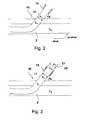
- FIG. 1a schematic human vascular system 1 is shown.
- the femoral arteries 2which is connected via a main artery to the aortic arch 3 and then opens into the heart chamber 4.
- an introducer sheath 10is first inserted into the femoral artery 2.
- the femoral artery or any blood vesselis punctured, for example with a steel cannula with a cutting tip.
- a guide wire 12is pushed through the steel cannula introduced into the puncture and inserted retrograde over the aortic arch 3 into the left ventricle of the heart 4.
- the first sheath 10which is designed as an introducer sheath, forms a tubular section 11 and optionally a dilator not shown here, threaded onto the guide wire and inserted through the punctured site into the vascular system, the lock being inserted a short distance into the lumen of the vasculature or even to the site of insertion of an inserted element.
- a fluid pumpis introduced through the introducer sheath 10 into the vascular system.
- the tubular portion 11 of the first sheath 10is inserted into the artery such that the proximal end of the first sheath 10 is outside the femoral artery and protrudes from the body of the patient and thus can be used for introducing, for example, a blood pump. So it is possible to thread the pump on the guide wire 12 to guide the pump with the help of the guide wire into the left ventricle.
- the methodis illustrated merely by inserting a pump into the left ventricle to support cardiac function.
- the pump or other functional elementmay also be located and placed at other locations in the body's own vasculature.
- FIG. 2is the area of Fig. 1 represented, in which the first lock 10 is guided by the body's own tissue from the outside into the lumen L G of the femoral artery 2.
- the first lockcomprises a tubular section 11 which is proximal to a lock housing 13 is connected.
- the tubular portion 11defines a lumen L 1 , which has an inner diameter d 11 .
- the lock housing 13includes a hemostatic valve known in the art. This prevents that fluid in the lumen L G can escape through the lumen L 1 to the outside.
- the first lock 10 of the Fig. 2coupled with a second lock 20.
- a tubular portion 21is shown, which defines a lumen L 2 with an inner diameter d 21 .
- the distal end of the second lock 20in this case has such an outer diameter that it can be inserted into the lock housing 13.
- the inner diameter d 21is larger than the inner diameter d 11, however .
- a not shown, located in the lumen L 2 pumpcan now be converted by pressing from the second sheath lumen L 2 in the first sheath lumen L1. Subsequently, the pump is transported through the first lock lumen L 1 to the point in the vascular system at which the pump is to be effective. In this case, the pump can either be guided on a guide wire or be introduced without guidewire through the first lock lumen.
- the first sheathmay be advanced distally to the pump site to save the pump and the vessel walls, as well as the shaft catheter, before the pump is pushed out.
- the pump 30comprises a distal pump unit 31 and a shaft catheter 32 adjoining the proximal end of the distal pump unit 31.
- the shaft catheter 32has at its proximal end, not shown, a coupling for coupling the shaft catheter 32 to a drive device.
- the drive devicecan be arranged outside the patient's body and sets a running in the shaft catheter 32 flexible shaft in rotation, which in turn the distal pump unit 31 drives.
- the present inventionis also suitable for introducing differently driven pumps (by means of an electric motor arranged on the pump or a pneumatic turbine arranged in the pump).
- the distal pump unitincludes a pump housing 33 made of intersecting Nitinol struts.
- the nitinol housingis in part provided with a coating 34 which extends distally and proximally of a rotor 35 arranged in the housing 33.
- the rotoris connected to the shaft 36 passing through the shaft catheter 32 and is thus rotated.
- the housing and the rotorare compressible, d. h., the pump is a self-decompressible pump. The deployment of the pump takes place after pushing out of the distal pump unit from the distal end of a lock.
- the distal pump unitis retracted into the distal end of a sluice lumen of a second sluice (auxiliary sluice).
- the lock lumenthereby has an inner diameter which may be greater than the outer diameter of the shaft catheter.
- the rotormay be displaceable relative to the pump housing in the axial direction, in particular by means of an axial displacement of the drive shaft.
- the rotorcan also be fixed in the axial direction with respect to the pump housing.
- the pumphas a discharge hose 37, which defines a flow channel for the pumped fluid located proximally of the rotor 35. At the proximal end of the discharge hose 37 are not shown outlet openings.
- the pumpcan also be switched from a pump mode to a suction mode, so that the pump no longer carries fluid from the distal end to the proximal end, but vice versa.
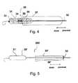
- a pump 30 'is shown, which is substantially the pump 30 after the Fig. 4 equivalent. For simplicity, details of the pump are not shown. Only the bulbous housing and the "pigtail" distal to the bulbous housing are shown, which prevents the heart pump from being sucked up against the heart wall. Proximal to the distal pump unit 31 'runs the wave catheter 32'. Surrounding a region 38 'of the shaft catheter 32' is a second sheath 20 'which comprises a lumen L 2 whose inner diameter d 21 is smaller than the diameter of the distal pump unit 31' in the deployed state.
- the in the Fig. 5 illustrated pump 30 'is a compressible pump, that is, the distal pump unit 31', which includes, inter alia, the pump housing and the rotor therein, is designed such that it can be compressed, ie reduced in diameter.
- a quality inspector or doctorfor example, has been able to convince himself of the correct function of the pump 30 ', e.g.
- pulling the shaft catheter 32' in the proximal directiondraws the distal pump unit 31 'into the lumen L 2 of the second sheath 20'.
- the systemcan be implemented with both actively decompressible pumps and self-decompressible pumps, it is particularly suitable for self-decompressible pumps, ie, pumps whose distal Pump unit outside the lock automatically returns to its original size.
- FIG. 6an intermediate step is shown in drawing the distal pump unit 30 'into the lumen of the second sheath 20'. It will be appreciated that the distal pump unit 30 'is compressible and can be made smaller in diameter so that the distal pump unit 30' can be received in the lumen of the second sheath 20 '.
- a coupling 39 'adjoining the shaft catheter 32'is provided, which allows a coupling of the shaft extending in the shaft catheter to a drive unit. Since the coupling 39 'often has a larger outer diameter than the inner diameter of the lumen L 2 , the second lock 20' is usually placed in the distal direction before the assembly of the coupling 39 'from the proximal end of the shaft catheter 32', so that the pump System 200, ie the pump with the proximal of the distal pump unit 31 'located second lock 20' and the preassembled coupling 39 ', is delivered. At the Fig. 6 is also a slight expansion of the distal end of the second lock 20 'shown. The trumpet-like widening 24 'facilitates the introduction of the distal pump unit 31' into the lumen L 2 of the second sheath 20 ',
- the distal pump unit 31 'is located completely in the lumen L 2 of the second sheath 20 ".
- the second sheath 20"has two preassembled handle units 22 ", which better hold or remove the second sheath 20" when the distal pump unit 31 is retracted 'allow in the lumen L 2 or a subsequent tearing.
- an auxiliary sluicecan be advantageously used, which permanently connected to the introducer sheath or kept in this.
- if there is a "pigtail”this is likewise drawn into the lumen L 2 , so that the distal pump unit 31 'together with components of the pump located distally of the distal pump unit 31' is located in the lumen L 2 .
- FIG. 8It can be seen how the system 200 of pump 30 'and second sheath 20 "is combined in operative connection with the first sheath 10 to form a system 100.
- the second sheath 20"auxiliary sheath
- the first sheath 10introduction sheath
- the pumpis displaced from the second sheath 20 'by pushing the pump in the distal direction, pushing by shunting the shaft catheter 32'.
- the diameter of the distal pump unit 31 'is further reduced to the inner diameter d 11 of the lumen L 1 .
- the subsequent stepis shown, in which the distal pump unit 31 'is located completely in the lumen L 1 of the first lock 10.
- the fact that the distal pump unit 31 'is located completely in the lumen L 1 of the first lock 10can be identified, for example, by means of a colored marking 50 which is applied on the outside of the shaft catheter 32'.
- the second sheath 20 "if formed as a" peel-away "sheath, may be removed from the shaft catheter 32 'by tearing the peel-away sheath from the proximal to the distal end and withdrawing from the shaft catheter 32'
- the directional tearing from the proximal to the distal endmay be assisted by notches A, but is primarily due to the alignment of the molecular chains of the plastic used from the proximal to the distal direction.
- the pump 30After the lock has been removed, if necessary, the pump 30 'continues to be guided within the lumen L 1 of the first lock 10 to the desired location.
- the first sheathmay also be advanced into the immediate vicinity of the site of use before or after insertion of the pump with the distal port mouth.
- the first lock on the necessary lengthmay also be advanced into the immediate vicinity of the site of use before or after insertion of the pump with the distal port mouth.
- a stiffening of the second sheath 20 "is in particular during insertion of the distal pump unit 31 'in the distal end of the second lock lumen L 2is not necessary, since the risk of kinking of the shaft is greatly reduced in a pulling movement.
- the second lockmay comprise a reinforcing structure in the form of an inserted wire, or the tubular portion 21 "of the lock 20" is not made of a flexible plastic, but of a dimensionally stable plastic or metal.
- Another way to stabilize the pump and the second lockis, when advancing the pump 30 'in the distal direction, d. H. in particular when transferring the pump 30 'from the second lock into the first lock, to hold the second lock 20 "by a support device 40 in the form of a stable outer sleeve and / or in a receiving channel of the introducer sheath.
- the pumpis first filled with sterile physiological saline and thus completely deaerated.
- the auxiliary sluice located proximally of the distal pump unitis advanced to a possibly existing outflow tube.
- the auxiliary sluicehas a diameter of, for example, 10 Fr.
- the auxiliary sluiceis surrounded by a sleeve-shaped, supporting device.
- the distal pump unitis drawn into the auxiliary sluice by a tensile movement in the proximal direction is exerted on the shaft catheter.
- the pumpis moved so far into the auxiliary sluice that a possibly existing pigtail is also recovered in the auxiliary sluice.
- any dilator presentis pulled out of the introducer sheath and removed.
- the pump held in the auxiliary sluicewhich for example is initially covered by the sleeve, is pushed into the sluice housing of the introducer sheath until the tip of the auxiliary sluice strikes against a mechanical stop.
- the pumpis transferred by pushing the shaft catheter from the auxiliary sheath into the tubular portion of the introducer sheath.
- the auxiliary sheathcan be left in the introducer sheath or, if appropriate, a peel-away sheath can be torn open and removed from the shaft catheter.
- the pumpis then advanced within the first sheath (introducer sheath) to the left ventricle.
- the first sheathis then withdrawn from the left ventricle to the beginning of the descending aorta.
- the positioning of the distal pump unit in the left ventricle of the heartcan be controlled, for example, by fluoroscopy.
- there is a radiopaque marking on the pump housing or in its vicinity, for example on the catheter, or the pump housing itselfis radiopaque.
- the outlet area of the pump, ie the outflow openings of a discharge hoseshould be in the region of the ascending aorta. This can also be checked with a radiopaque marker. Any existing pigtail catheter tip should abut the tip of the left ventricle of the heart.
- the shaft cathetermay have a feed funnel into which the pump can be pulled by train on the drive shaft. Subsequently, the first lock and other remaining components are removed from the vascular system.
- a particular advantage of the inventionis the use of a long lock, in particular as an introducer sheath during the implantation and explantation of the pump.
- the long sluiceis not only used, as is common in the prior art, for introducing the pump into an endogenous lumen, but for guiding the pump through the sluice lumen in the vicinity of the site of action.
- the lockhas a length between 40 and 120 cm. The length is determined by the later place of action of the pump and the physique of the patient.
- the pumpis pulled out of the body's own lumen together with the long sluice, the bleeding of the femoral artery is stopped with a pressure bandage.
- the pumpcan be pulled out of the lock lumen of the long lock.
- another guidewirecan be placed through the lumen of the sluice, and then, after removal of the sluice, a device for closing the puncture can be guided. This achieves improved hemostasis.
- FIGS. 10 to 13specifically show an inventive embodiment of the first lock with one or more clamping devices for fixing a tubular portion 41 in a lock housing 43rd
- FIG. 10shows in a longitudinal section a lock housing 43, which has substantially the shape of a cylindrical sleeve, which is closed at least at the distal, the patient's body-facing end 44 by a pressure screw 45.
- the lock housing 43has a continuous receiving channel 46 for a tubular portion 41 the lock on.
- the tubular portion 41In the presentation of the Fig. 10 is the tubular portion 41 until in the washing chamber 47 of the receiving channel 46 continuously, then shown in phantom in the proximal direction. This indicates that the tubular portion 41 is axially displaceable with respect to the lock housing 43 within the receiving channel 46 or, in other words, that the lock housing 43 is slidable on the tubular portion 41.
- the lock showncan be used, for example, as an introducer sheath (first sheath).
- the tubular section 41is usually pulled out of the sheath housing 43 in the distal direction or positioned in the production of the first sheath such that it ends approximately at the level of the first stop piece 48, and then clamped for example by pressing the pressure screw 45.
- a second lock with a retracted pumpas described above, can then be advanced to then move the pump from the second lock to the first lock.
- the first clamping devicehas as a fastening means the first pressure screw 45, a first clamping ring 50 made of an elastomeric material and the first stop piece 48. Between the clamping ring 50 and the pressure screw 45, a sliding layer or a sliding ring 69 may be provided.
- the pressure screwis screwed by means of an external thread in the region of the overlap with the distal end 44 of the lock housing 43 with this.
- a manual rotation of the pressure screw 45thus causes a movement of the pressure screw in the axial direction, which leads to an axial compression or expansion of the clamping ring 50.
- the clamping ring 50tends to dodge radially inwardly and outwardly to maintain its volume and thus clamps the tubular portion 41 because it experiences resistance on its proximal side by the first stopper 48.
- the tubular portion 41is fixed axially against the lock housing 43. This fixation can be solved simply by loosening the pressure screw 45, so that the tubular portion 41 can then easily be moved axially in the lock housing 43.
- the clamping ringmay have an inner diameter in the relaxed state, which is equal to or greater than the diameter of the first lock.
- the tubular portion 41as far as possible pushed into the patient's body to allow insertion of the pump in the protection of the lock to the place of use, for example in a Herzventrikel, so after deployment of the pump, the tubular portion 41 is pulled out, and the lock as a whole protrudes relatively far from the patient's body. Thereafter, the clamping device 48, 45, 50 dissolved and the lock housing 43 are pushed on the tubular portion 41 closer to the patient's body. In this case, the tubular portion 41 then passes through the lock housing 43 completely and possibly projects out of it in the proximal direction. Thereupon, by means which will be described in more detail below, the tubular portion 41 may be partially severed to remove the excess length.
- a so-called combined hemostasis valveconsisting of a dome valve 51 and a valve plate 52, is provided for better sealing.
- the valve platecloses the lock housing 43, if at this point neither the tubular portion 41 nor a wave catheter penetrates the receiving channel 46, while the dome valve 51 is optimized around a string-shaped body, for example the tubular portion or a catheter.
- a further pressure screw 54is provided, which works in principle as well as the first pressure screw 45 and via a pressure piece 55 causes the compression of a second clamping ring 56 relative to a second mechanical stop 57.
- a catheter or an inserted auxiliary lockcan be clamped in the introducer sheath.
- the second clamping ring 56tapers at its distal end, which promotes a deformation radially inwardly when exerting an axial pressure by the pressure screw 54.
- the second stop 57is conical. However, it can also be used at this point a non-conical, but in cross-section rectangular or round clamping ring 56.
- a flushing device 58schematically indicated, which allows the flushing of the washing chamber 47, which is the interior of the lock housing, with a liquid which prevents the penetration of germs through the first lock in the patient's body.
- This flushingis particularly effective when the tubular portion 41 terminates in the flushing space 47 or on the distal side thereof, so that both the outside and the inside of the tubular portion 41 are reached by the flushing liquid.
- FIG. 11shows an example of the arrangement and operation of a cutting device according to the invention.
- predetermined breaking pointsare provided, these can be appropriately introduced when using the first lock by a cutting device.
- a cutting device with blades 59, 60are provided, which intersect in the circumferential direction, for example, upon rotation of the lock housing relative to the tubular portion. It can also be introduced cuts in the axial direction.
- the blades 59, 60may also be arranged so that they intersect in the axial direction, as indicated by the arrow 61, during a movement of the tubular portion 41 in the longitudinal direction. It is also possible to provide both blades for cutting in the circumferential direction and a blade for cutting in the longitudinal direction.
- the blades 59, 60can be moved in the direction radially to the tubular portion 41 by an operation from the outside of the lock housing 43.
- a pressure on the bladescan then be exerted by hand and the unneeded part of the tubular portion 41 can be cut off.
- An abutmentprevents the depth of cut from exceeding a critical level, thereby damaging any catheter within the sheath.
- the illustrated bladesmay also form a cutting device for a second lock.
- FIG. 12shows an advantageous use of the second clamping device on the proximal side of the lock housing 43 after the tubular portion 41 is shortened and a shaft catheter 61 from the proximal end of the tubular portion 41 out and on to a not shown coupling device for a drivable shaft of a pump from the Lock housing 43 leads.
- the shaft catheteris sealed in the above-mentioned mandrel seal 51, and the clamping device with the elements of the second pressure screw 54 and the second clamping ring 56, which is axially compressed by the pressure piece 55 relative to a second stop 57, so far deviates radially inwardly he the shaft catheter 61, which has a substantially smaller outer diameter than the tubular portion 41 or a second lock, clamps and in particular also additionally seals.
- a rotation of the shaft rotatable thereinis not hindered by the clamping. In this way, both the tubular portion 41 and the shaft catheter 61 protruding therefrom can be fixed in the lock housing 43.
- the second clamping deviceis also suitable, when inserting a second lock into the lock housing 43, to fix the second lock with the second clamping ring 56 so that it is sufficiently fixed relative to the lock housing 43 and in particular also to the tubular section 41 for pushing through the shaft catheter 61 is.
- the first and second clamping ring 50, 56may be made of an elastomer, such as a rubber or a silicone elastomer, and thus be fully elastic, but volumeninkompressibel deformable. However, it is at this point also the use of an elastic foam conceivable, which is partially volumenkompressibel.
- a clamping ring 56may be provided for producing a clamping connection and a radially displaceable spring clip, as in the FIGS. 13g, 13h, 13i shown and explained below.
- a corresponding spring clipmay be provided in addition to or instead of a clamping ring.
- the spring clipmay be in the area of dotted lines 70 in Fig. 12 be provided.
- the spring clipin the region of the dashed line 70 ', since this region is located proximal to the seal 51 and thus does not have to be particularly stringent in the tightness of the sliding arrangement of the spring clip.
- FIGS. 13a to 13ishow clamping devices and / or fastening devices for locks, which can be used individually or in combination in each case at an introducer sheath, and / or an auxiliary sheath.
- FIG. 13ais schematically shown a type of clamping ring 62, which may for example consist of a plastic or a metal and in particular slotted and thus radially compressible.
- the slotted clamping ring 62has a conical outer contour against which the conical contour of a pressure piece 63 presses to radially compress the clamping ring as soon as an axial compressive force in the direction of the arrow 65, for example by a pressure screw shown above, is exerted on the pressure piece 63 ,
- the slotted clamping ring 62is fixed axially by the stopper 64.
- FIG. 13bshows within a lock housing 43, a fitting 71 having a through-passage 72, wherein on the cylindrical surface of the through-channel 72 circumferential grooves and ridges 73 are provided, which mate with grooves and beads 74 of a Gegenpass Facultys 75 on the body 76 to be clamped.
- the counter-fit piece 75is elastically snap-fitted into the fitting piece 71 and is held there, advantageously sealing.
- a stop piece 77prevents too far insertion of the body 76 and makes the engagement of the compound haptically palpable.
- FIG. 13cshows a similar arrangement as Fig. 13b , wherein the fitting 71 'and the counter-fitting 75' are each provided with a thread instead of concentric circumferential grooves and beads.
- the counter-fitting 75 'can be moved by turning in the fitting 71', but also overcoming the thread and axial insertion is conceivable.
- a visible mark 78is provided on the body 76 to be clamped to identify the target position.
- itcan also be provided a shape marking that makes the target position tactile or audible perceptible, or it may be provided a mechanism for actuating an electrical contact for signaling when reaching / leaving the desired position.
- FIG. 13dshows on the body 76 to be clamped a cone 79 which fits into a conical recess 80 of the fitting 71 'sealing.
- the cone 79has one or more peripheral pins 81, which are guided in scenes 82 on the inner circumferential surface of the recess 80 and serve to form a bayonet-type locking. It can also be reversed on the outer cone a pin and the inner cone provided a backdrop. It can be formed in compliance with the appropriate standards by the connection of sealing cone and locking a so-called Luer-Lock. Instead of the bayonet lock may be provided in conjunction with the cone system and a threaded connection.
- FIG. 13eshows in a rotated side view of the cone 79 with two pins 81st
- FIG. 13fa cone system with a cone 79 'and a surrounding threaded nut 83 is shown.
- the threaded nut 83is screwed onto a thread of the pipe socket 84, which is connected to the fitting 85.
- the fitting 85is firmly installed in the lock housing 43 of an introducer and has an inner cone.
- the threaded nut 83can also be designed as free relative to the cone 79 'rotatable cap nut.
- the Figure 13gshows a lock housing with a radially displaceably guided spring clip, which is actuated by means of a slide button 87. There is provided a stop 88 which stops the slide button 87 in the target position. In addition, an optically recognizable marking can be provided on the spring clip.
- the spring clip 86runs when entering the lock housing in a counter guide 89 a. Before the spring clip is elastically widened when hitting the body 76 to be clamped. For this purpose, she points out, as in FIG. 13i shown, an inlet opening 90. Upon further insertion, the receiving area 91 lays around the body to be clamped. This one can, like out FIG. 13h can be seen, a circumferential groove or groove 92 or a sleeve 93 having such a groove 92. The functions of the clamp and the seal on the body to be clamped are separated in this embodiment.
- the clampingcan also be prepared by the spring clip is fully retracted into the lock housing 43 and only then is the body to be clamped, for example a catheter or a second lock, introduced axially.
- the conical starting slope 94allows the sleeve 93 can be inserted with the body to be clamped in the spring clip 86 and held there.
- the body to be clamped / a second sheath in a first sheathcan also be held by elastic, self-locking lamellae, scales or teeth which lock the sheath out of the sheath or make it significantly more difficult to pull it out.
- such finsare on the left side of the Fig. 13d represented and designated there with 95.
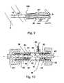
- the Fig. 14shows a lock housing 43 'an introducer, having in its interior a receiving channel 46 for a lock or a catheter.
- the lock housing 43 'has at its distal end 44 on this attached tubular portion 41, which can be glued, for example, in an opening of the lock housing, cast or otherwise secured there.
- the tubular portion 41is inserted into the opening of the lock housing 43 'up to a mechanical stop 63.
- a second sheath 20 "'(auxiliary sheath) is pushed into the receiving channel 46 so that it ends distally on the mechanical stop 63.
- the systemcan also be designed so that the second lock 20 '"ends directly at the tubular portion 41.
- the second lock 20 "'is, not shown, for example, retracted a functional element in the form of a pump with a hollow catheter.
- the clamping devicehas an elastic clamping ring 56 ', which is tapered at its distal end and is pressed against a mechanical stop 57'.
- a pressure screw 54 'which has an external thread 64, axial pressure on the clamping ring 56' is exercised.
- the pressure screw 54 'is screwed for this purpose in the opening of the tubular part of the lock housing 43', so that it moves axially in the direction of the arrow 65.
- a sliding ring 69for example made of PTFE or other good sliding plastic.
- the clamping ring 56 'consists for example of an elastomer, expands at an axial pressure in the radial direction and thus clamps a strand-shaped Body which is located in the receiving channel 46.
- the body to be clampedcan have, for example, one or more circumferential beads, webs, grooves or grooves or edges in order to improve the attack during the clamping.
- a cuffcan also be provided on the body.
- the second lock 20has a wall thickness between 0.3 and 0.7 mm and is made of a sufficiently stable material, so that at radial pressure, the second lock can be clamped, without at the same time the catheter extending therein is clamped with Thus, the catheter can easily be displaced from the proximal end of the second sheath 20 '"into the tubular section 41.
- the second lock 20is sealed by a combined plate and dome seal 51, 52 in a wash chamber 47.
- the second lockcan be torn open and removed by means of the handles 67, 68.
- the second lockcan be a Have a pre-weakening or an incision along its axial direction or a corresponding predetermined molecular structure, which allows a longitudinal tearing to the distal end of the second sheath and a corresponding removal of the second sheath. to solve.
- the clamping device 54 ', 56', 57 'are clamped so far that the smaller diameter catheter is clamped by the further radial compression of the clamping ring 56' in the receiving space 46.
- the second lock(auxiliary lock) can also be designed so that it can remain in the introducer sheath. It is then to ensure adequate sealing and flushing, as will be explained below.
- the clamping devicecan be released and the catheter readjusted and fixed again.
- two cylindrical elementsare sealingly inserted into one another in the construction described, it is advantageous to use a cone seal with a cone angle of a few degrees, as is generally known in the medical field.
- a lockallows, for example, an implantable heart pump from a second lock, in which it can be kept in stock after a first inspection, in a first lock, which leads into a patient's body, without problems and with little effort and high reliability convict,
- FIG. 15shows on the right side an introducer sluice 101 and on the left side of an auxiliary sluice 104, the hose-like part 112 can be inserted into the introducer sluice 101 and there is verkêtmbar.
- the introducer sheath 101essentially corresponds, as does the auxiliary sheath 104, to the one in FIG Fig. 14 illustrated and described in this context lock.
- the whole in the Fig. 15The lock arrangement shown comprises the introducer sheath and the auxiliary sheath and is suitable for introducing a strand-shaped body / catheter 105 through the auxiliary sheath 104 into the introducer sheath 101 and through it into a patient's body.
- the introducer sheath 101has for this purpose at its distal end 102 a tubular part 41 a, which is sealed in the proximal part 103, which forms a lock housing 114 is attached.
- the tubular part 112 at the distal end of the auxiliary sheath 104can be inserted into the introducer sheath 101 and pushed to a stop 63 in front of the tubular part of the introducer sheath.
- the introducer sheathhas first attachment means 106, which may for example be of similar construction to the second attachment means 107 of the auxiliary sheath 104 and closer in connection with the clamping device Fig. 14 have been described. In principle, however, the first and second fastening means may each of the in the FIGS. 13a to 13i include attachment types shown by way of example.
- a flushing device 108is provided with a corresponding flushing hose and an opening provided in the wall of the housing 114 .
- the purging deviceis connected to a flushing agent source 120, which comprises, for example, a pump 121 and a reservoir 122.
- the auxiliary lock 104likewise has a flushing device 109, which comprises a flushing hose and an opening in the wall of the housing 113.
- the first flushing device 108is connected, for example, to the second flushing device 109 via the flushing agent source 120. It can be provided that the pump 121 in both the first flushing device 108 and in the second flushing device 109 rinsing agent carried in order to convey this in the interiors of the housing 113, 114.
- FIG. 16 1shows a variant in which the flushing agent source 120 delivers flushing agent into the housing interior 110 of the housing 114 of the introducer sheath 101 via the first flushing device 101, wherein the tube-like part 112 of the auxiliary sheath fixed inside the introducer sheath at least 110 in the interior space 110 a shell-side opening 119, for example, a shell-side perforation consisting of many openings, through which the flushing agent can penetrate into the tube-like part 112 and through this axially to the housing interior 111 of the housing 113 can flow.
- the rinsing agentcan actively move from the rinsing agent source 120 through the introduction sluice 101 into the auxiliary sluice 104.
- the constructive devices of the second flushing device 109can serve, for example, for venting the auxiliary airlock or for removing the flushing liquid there in order to collect it in a collecting tank 123.
- the interior of the hose-like part 112 of the auxiliary lockforms part of the auxiliary flushing channel 115 'for connecting the two locks Fig. 15 shown variant, such a Hilfs Serieskanal 115 is given by the supply hoses of the purging devices 108 and 109 or their connection.
- the shell-side openings / recesses 119 in the tube-like part 112 of the auxiliary sluicecan, for example, also be introduced into the part 112 only after the catheter has been introduced into the patient's body.
- a cutting assemblyas shown in the Fig. 11 is shown.
- FIG. 17a construction is shown in which the lock housing 114 of the introducer sheath is firmly connected to the lock housing 113 of the auxiliary sheath 104.
- the two lock housingsare firmly interlocked in a cylindrical or slightly conically shaped portion. It can also be provided here a threaded connection or a bayonet connection.
- annular groove 116is formed, which is formed, for example, as in the illustrated version by annular grooves in the housing 113 of the auxiliary lock on the one hand and in the housing 114 of the introducer sheath on the other. But it may also be sufficient to provide an annular groove only in one of the housing.
- the annular groove or both annular groovesare connected via a respective channel-like recess 117, 118 which extends through the wall of the respective housing 114, 113, with a first flushing device 108 and the interior of the respective lock housing 114, 113.
- the second flushing device 109serves in this case as in the Fig. 16 for venting and for draining flushing fluid. But it can also be reversed flushing of both housings provided by the second flushing device.
- a resilient slideon the inner peripheral side of the housing 114 and on the outside of the housing 113 in each case in the region of the annular groove, that the corresponding annular grooves and / or channel-like recesses are covered before the connection of the two housings.
- the slidesshould be spring loaded and retractable such that they release the respective annular grooves or recesses when joining the two housings.
- the channel-like recesses 117, 118 and the annular groove 116form in the case of the construction Fig. 17 the auxiliary scavenging passage 115 ".
- the described variantsmake it possible to leave the auxiliary sluice 104 permanently connected to the introducer sheath, 101 and connected thereto, and to flush both together in such a way that the penetration of germs into the patient's body can be reliably prevented in the region of the sluice.
- FIG. 18shows a design of the lock assembly, in which at a introducer sheath 101, a sterile tube 130 is attached fluid-tight. This can basically from the introducer sluice 101 or an auxiliary sluice 104 '(in Fig. 18 only partially and schematically shown) to be flushed out.
- the sterile tube 130is itself fluid-tight and formed as a corrugated tube. It can by means of a flange or adhesive connection 131 or generally means one of the in the FIGS. 13a to 13i shown connection types with the housing of the introducer sheath 114 and / or the housing of the auxiliary sheath and / or a catheter handle and at least partially surrounds an auxiliary sheath, which is partially inserted into the introducer sheath.
- the sterile tubecan also be clamped directly to the catheter shaft proximally.
- auxiliary sheathAfter inserting a catheter into a patient's body, the auxiliary sheath can be completely received in the sterile tube 130.
- a proximal end piece 132has a passageway for the catheter, which is sealed there.
- the sterile tubecan be axially compressed and, for example, the end piece 132 can be connected to a flange 131.
- the auxiliary sluicecan also be torn open as a peel-away sluice and pulled out of the introducer sheath into the sterile tube in order to remain there. The introducer sheath can then be sealed against the sterile tube.
Landscapes
- Health & Medical Sciences (AREA)
- Heart & Thoracic Surgery (AREA)
- Engineering & Computer Science (AREA)
- Life Sciences & Earth Sciences (AREA)
- Animal Behavior & Ethology (AREA)
- Hematology (AREA)
- Anesthesiology (AREA)
- Biomedical Technology (AREA)
- General Health & Medical Sciences (AREA)
- Public Health (AREA)
- Veterinary Medicine (AREA)
- Cardiology (AREA)
- Mechanical Engineering (AREA)
- Pulmonology (AREA)
- Biophysics (AREA)
- Vascular Medicine (AREA)
- Media Introduction/Drainage Providing Device (AREA)
- Infusion, Injection, And Reservoir Apparatuses (AREA)
Abstract
Translated fromGermanDescription
Translated fromGermanDie Erfindung liegt auf dem Gebiet der Mechanik und ist mit besonderem Vorteil in der Medizintechnik anwendbar. Sie bezieht sich speziell auf eine Schleusenanordnung, die es ermöglicht, einen strangförmigen Körper, insbesondere einen Katheter, wenigstens teilweise in einen Patientenkörper einzuführen.The invention is in the field of mechanics and is particularly applicable in medical technology. It relates specifically to a lock arrangement which makes it possible to introduce a strand-shaped body, in particular a catheter, at least partially into a patient's body.
Grundsätzlich ist es bekannt, zur Einführung eines Katheters in einen Patientenkörper, beispielsweise in ein Blutgefäß, eine Einführschleuse zu benutzen, deren proximales Ende aus dem Patientenkörper herausragt, während das distale Ende dauerhaft im Patientenkörper verbleibt. Solche Einführschleusen können beispielsweise einwachsend gestaltet sein, sie können jedoch auch einfach steril durch die Haut oder eine Körperöffnung des Patienten eingeführt werden. Eine solche Schleuse ist beispielsweise vorteilhaft, wenn ein Katheter in ein Blutgefäß eines Patienten eingeführt und aus diesem auch wieder entnommen werden soll. Eine besondere Anwendung solcher Katheter stellen Katheter mit Funktionselementen dar, beispielsweise Hohlkatheter, an deren Ende sich eine Blutpumpe befindet, die durch ein Blutgefäß bis zu einer Herzkammer oder bis zu einem größeren Blutgefäß transportiert wird, um dort gegebenenfalls expandiert zu werden. Entsprechende Blutpumpen, die expandierbar und später wieder komprimierbar sind, sind aus der Literatur vielfältig bekannt.In principle, it is known to use an introducer sheath for introducing a catheter into a patient's body, for example into a blood vessel, the proximal end of which protrudes from the patient's body, while the distal end remains permanently in the patient's body. Such introducer sheaths may, for example, be designed to grow in, but they may also simply be introduced through the skin or a body opening of the patient in a sterile manner. Such a lock is advantageous, for example, when a catheter is inserted into and out of a patient's blood vessel should be removed again. A particular application of such catheters are catheters with functional elements, for example hollow catheters, at the end of which there is a blood pump, which is transported through a blood vessel to a heart chamber or to a larger blood vessel in order to be optionally expanded there. Corresponding blood pumps, which are expandable and later compressible again, are widely known from the literature.
Als Funktionselemente können jedoch auch andere Geräte an dem Katheter befestigt sein, wie beispielsweise Fräsen zur Beseitigung von Ablagerungen in Blutgefäßen oder ähnliche.As functional elements, however, other devices may be attached to the catheter, such as milling for the removal of deposits in blood vessels or the like.
Speziell zur Einführung von Katheterpumpen ist bereits vorgeschlagen worden, zusätzlich zu einer Einführschleuse eine Hilfsschleuse zu verwenden, in die der Katheter mit der komprimierten Pumpe eingebracht werden kann, wobei die Hilfsschleuse den endseitigen Teil des Katheters sowie die komprimierte Pumpe vorübergehend aufnimmt und gemeinsam mit der Pumpe in die Einführschleuse eingeführt wird.Specifically for the introduction of catheter pumps has been proposed to use in addition to an introducer sheath an auxiliary sheath into which the catheter can be introduced with the compressed pump, the auxiliary sheath temporarily receives the end portion of the catheter and the compressed pump and together with the pump is introduced into the introducer sheath.
Es ist bekannt, innerhalb einer Schleuse dort, wo ein Gegenstand in die Schleuse eingeführt wird, eine Spüleinrichtung innerhalb eines Schleuseninnenraums vorzusehen, um vor dem Einführen oder während des Einführens durch das Spülen des einzuführenden Körpers und/oder des Schleuseneingangs das Eindringen von Keimen beziehungsweise Luft in den Patientenkörper zu verhindern. Zudem ist es auch bekannt, an derartigen Schleusen Dichtungseinrichtungen vorzusehen, um einerseits vor dem Einführen eines Körpers durch die Schleuse das Austreten von Blut oder anderen Körperflüssigkeiten aus der Schleuse zu verhindern und andererseits während des Einführens eines Körpers in die Schleuse die Öffnung, durch die der Körper in die Schleuse eingeführt wird, so weit wie möglich gegenüber dem Außenbereich abzudichten.It is known, within a lock where an object is introduced into the lock, to provide a flushing device within a lock interior in order to prevent the entry of germs or air before insertion or during insertion by flushing of the inserted body and / or the lock entrance to prevent the patient's body. In addition, it is also known to provide sealing means on such locks, on the one hand before the introduction of a body through the lock to prevent the escape of blood or other body fluids from the lock and on the other hand, during the insertion of a body in the lock the opening through which the Body is introduced into the lock, as far as possible to seal against the outside area.
Der vorliegenden Erfindung liegt vor dem geschilderten Hintergrund die Aufgabe zugrunde, eine Schleusenanordnung mit einer Einführschleuse und einer Hilfsschleuse zu schaffen, die das Einführen eines strangförmigen Körpers, insbesondere eines Katheters, mittels der Hilfsschleuse in die Einführschleuse in möglichst komfortabler Weise erlaubt und dabei insgesamt das Eindringen von Keimen oder anderen unerwünschten Gegenständen und Stoffen in den Patientenkörper möglichst weitgehend verhindert. Zudem soll die Schleusenanordnung möglichst gut gegen das Austreten von Körperflüssigkeiten geschützt sein.The present invention is based on the background described the object to provide a lock assembly with an introducer sheath and an auxiliary sheath, the insertion of a strand-shaped body, in particular a catheter, by means of the auxiliary sheath in the Einführschleuse allowed in the most comfortable way and while preventing as much as possible the penetration of germs or other undesirable objects and substances in the patient's body. In addition, the lock assembly should be as well protected against leakage of body fluids.
Die Aufgabe wird mit den Merkmalen der Erfindung gemäß Patentanspruch 1 gelöst.The object is achieved with the features of the invention according to
Demgemäß bezieht sich die Erfindung auf eine Schleusenanordnung für die Einführung eines strangförmigen Körpers, insbesondere eines Katheters, in einen Patientenkörper mit einer Einführschleuse, deren distales Ende zum Einbringen in einen Patientenkörper vorgesehen ist und deren proximales Ende beim Einbringen des distalen Endes in einen Patientenkörper aus diesem herausragt, und mit einer Hilfsschleuse zur Einführung in die Einführschleuse gemeinsam mit dem strangförmigen Körper / Katheter, mit ersten Befestigungsmitteln zur, insbesondere lösbaren, Befestigung der Hilfsschleuse an der Einführschleuse, mit zweiten Befestigungsmitteln zur, insbesondere lösbaren, Befestigung des strangförmigen Körpers an der Hilfsschleuse, wobei die Einführschleuse einen ersten Schleuseninnenraum mit einem ersten Aufnahmekanal für einen strangförmigen Körper sowie eine erste Spüleinrichtung zum Spülen des Schleuseninnenraums aufweist, wobei die Hilfsschleuse einen zweiten Schleuseninnenraum mit einem zweiten Aufnahmekanal für einen strangförmigen Körper sowie eine zweite Spüleinrichtung für den zweiten Schleuseninnenraum aufweist.Accordingly, the invention relates to a lock assembly for the introduction of a strand-like body, in particular a catheter, in a patient's body with an introducer sheath, whose distal end is intended to be inserted into a patient's body and the proximal end thereof when inserting the distal end into a patient's body protruding, and with an auxiliary sluice for introduction into the introducer sheath together with the strand-shaped body / catheter, with first attachment means for, in particular detachable, attachment of the auxiliary sluice to the introducer, with second attachment means for, in particular detachable, attachment of the strand-shaped body to the auxiliary sluice, wherein the introducer sheath having a first lock interior with a first receiving channel for a strand-like body and a first flushing device for flushing the lock interior, wherein the auxiliary lock a second lock having inner space with a second receiving channel for a strand-like body and a second flushing device for the second lock interior.
Bei der erfindungsgemäßen Schleusenanordnung ist sichergestellt, dass die Hilfsschleuse dauerhaft und zuverlässig an der Einführschleuse befestigt werden kann und dass so sowohl die Einführschleuse als auch die Hilfsschleuse gespült und damit sauber und keimfrei gehalten werden kann. Im Inneren der Einführschleuse kann der Innenraum zwischen der Hilfsschleuse und der Einführschleuse bzw. zwischen dem distalen Teil der Hilfsschleuse und der Einführschleuse gespült und damit keimfrei gehalten werden. Innerhalb der Hilfsschleuse kann der Innenbereich der Hilfsschleuse mit dem in dieser befindlichen oder in diese hineinragenden strangförmigen Körper, insbesondere Katheter, gespült und damit keimfrei gehalten werden. Es ergibt sich damit eine Gesamtanordnung, die dauerhaft mechanisch zusammenhält, zumindest bis die Verbindung zwischen der Einführschleuse und der Hilfsschleuse willentlich gelöst wird, und die am Übergang von der Einführschleuse zur Hilfsschleuse und am Übergang von der Hilfsschleuse zum in dieser befindlichen strangförmigen Körper in einfacher Weise eine Spülung zulässt. Damit kann sichergestellt werden, dass einerseits die Zahl der Keime und/oder anderen Verunreinigungen, die von außen in die Einführschleuse gelangen, minimiert wird und andererseits der Blutaustritt aus der Einführschleuse und der Hilfsschleuse verhindert wird.In the lock arrangement according to the invention, it is ensured that the auxiliary lock can be permanently and reliably fastened to the introducer sheath and that both the introducer sheath and the auxiliary sheath can be flushed and thus kept clean and germ-free. Inside the introducer sheath, the interior space between the auxiliary sheath and the introducer sheath or between the distal part of the auxiliary sheath and the introducer sheath can be rinsed and thus kept germ-free. Within the auxiliary sluice, the inner area of the auxiliary sluice can be flushed with the strand-shaped body, in particular catheter, which is located in or protruding into it, and thus kept germ-free. It turns out Thus, an overall arrangement that holds together permanently mechanically, at least until the connection between the introducer sheath and the auxiliary sheath will be solved willingly, and at the transition from the introducer sheath to the auxiliary sheath and at the transition from the auxiliary sheath to the present in this strand-like body in a simple manner allows a purge , This ensures that, on the one hand, the number of germs and / or other contaminants entering the introducer sheath from the outside is minimized and, on the other hand, blood leakage from the introducer sheath and the auxiliary sheath is prevented.
Eine vorteilhafte Ausgestaltung der Erfindung sieht vor, dass die Hilfsschleuse einen schlauchartigen, distalen Teil und ein proximales Schleusengehäuse aufweist und dass nur der schlauchartige Teil mit der Einführschleuse, insbesondere lösbar, verbunden ist.An advantageous embodiment of the invention provides that the auxiliary sluice has a tubular, distal part and a proximal sluice housing and that only the tubular part with the introducer, in particular releasably, is connected.
Dabei kann der schlauchartige Teil der Hilfsschleuse in einfacher Weise innerhalb der Einführschleuse geklemmt und damit lösbar befestigt sein. Innerhalb der Hilfsschleuse kann durch eine Spüleinrichtung die Außenseite des schlauchartigen Teils der Hilfsschleuse und das Innere der Einführschleuse mittels einer Spüleinrichtung keimfrei gehalten werden. Innerhalb des schlauchartigen Teils der Hilfsschleuse kann beim Einführen dieses Teils in die Einführschleuse bereits ein strangförmiger Körper / Katheter, beispielsweise mit einer komprimierten Blutpumpe, enthalten sein. Die Blutpumpe kann dann nach Einführen des schlauchartigen Teils der Hilfsschleuse in die Einführschleuse seinerseits von der Hilfsschleuse in die Einführschleuse, beispielsweise einen schlauchartigen Teil der Einführschleuse, überführt werden. Dabei wird gleichzeitig durch Spülen des Schleuseninnenraums der Einführschleuse die Keimfreiheit der Umgebung bei dem Transfervorgang sichergestellt.In this case, the tubular part of the auxiliary lock can be clamped in a simple manner within the introducer sheath and thus releasably secured. Within the auxiliary sluice, the outside of the tubular part of the auxiliary sluice and the interior of the introducer sluice can be kept germ-free by means of a rinsing device by means of a rinsing device. Within the tube-like part of the auxiliary sluice a strand-shaped body / catheter, for example with a compressed blood pump, can already be contained when this part is introduced into the introducer sheath. The blood pump can then be transferred after insertion of the tubular part of the auxiliary sluice in the introducer sluice in turn from the auxiliary sluice in the introducer sheath, for example a tubular part of the introducer sheath. At the same time, by flushing the lock interior of the introducer sheath, the sterility of the environment during the transfer process is ensured.
Mit der Einführschleuse kann stirnseitig ein Sterilschlauch fluiddicht verbunden sein, in dem der schlauchartige Teil der Hilfsschleuse angeordnet sein kann. Der Sterilschlauch kann mit der Hilfsschleuse, insbesondere deren Gehäuse, fluiddicht abschließen. Der Sterilschlauch kann axial komprimierbar sein, um nach dem Einbringen des strangförmigen Körpers in die Einführschleuse die Hilfsschleuse, insbesondere deren schlauchförmigen Teil, in die Einführschleuse einzuschieben und dort zu belassen. Der Sterilschlauch kann beispielsweise als Wellschlauch ausgeführt sein.With the introducer sheath, a sterile tube can be fluid-tightly connected to the end, in which the tube-like part of the auxiliary sheath can be arranged. The sterile hose can be fluid-tight with the auxiliary lock, in particular its housing. The sterile tube may be axially compressible to after the introduction of the strand-like body in the introducer sheath, the auxiliary sheath, in particular the tubular part in the Insert introducer sheath and leave it there. The sterile hose can be designed, for example, as a corrugated hose.
Eine weitere vorteilhafte Ausgestaltung der Erfindung sieht vor, dass die Hilfsschleuse einen schlauchartigen, distalen Teil und ein Schleusengehäuse aufweist und dass das Schleusengehäuse der Hilfsschleuse, insbesondere lösbar, mit der Einführschleuse, insbesondere mit einem Schleusengehäuse der Einführschleuse, verbunden ist.A further advantageous embodiment of the invention provides that the auxiliary sluice has a tube-like, distal part and a lock housing and that the sluice housing of the auxiliary sluice, in particular detachably, is connected to the introducer sheath, in particular to a sluice housing of the introducer sheath.
Wenn das Schleusengehäuse der Hilfsschleuse mit dem Schleusengehäuse der Einführschleuse fest verbunden ist, so ergibt sich insgesamt eine feste und unverformbare Einheit, die am Patientenkörper besonders einfach zu handhaben ist. Es ist dann auch besonders einfach, den strangförmigen Körper durch die Hilfsschleuse hindurch in die Einführschleuse einzuschieben. Nach der Verbindung der Hilfsschleuse mit der Einführschleuse wirkt die Schleusenanordnung wie eine einzige, mehrstufige Schleuse.If the sluice housing of the auxiliary sluice is firmly connected to the sluice housing of the introducer sheath, the result is a total of a solid and non-deformable unit which is particularly easy to handle on the patient's body. It is then also particularly easy to insert the rope-shaped body through the auxiliary lock into the introducer sheath. After the connection of the auxiliary sluice with the introducer sluice, the sluice arrangement acts as a single, multi-stage sluice.
Die Erfindung kann außerdem vorteilhaft dadurch ausgestaltet werden, dass die Verbindung der Hilfsschleuse mit der Einführschleuse als lösbare Klemmverbindung mit Kraft- oder Reibschluss, als Doppelkonusverbindung, Schraubverbindung, Bajonettverbindung, Presspassung oder andere lösbare Passverbindung ausgeführt ist. Derartige lösbare Verbindungen sind auch unter Operationsbedingungen einfach herstellbar und wieder lösbar. Wegen der einfachen mechanischen Funktion werden keine chemisch aktiven Fügemittel benötigt, und es gibt somit keine Kontaminationsrisiken bei der Verwendung am lebenden Patienten. Die Lösung der entsprechenden Verbindung ist ebenso einfach wie die Herstellung der Verbindung.The invention can also advantageously be configured in that the connection of the auxiliary lock with the introducer sheath is designed as a detachable clamping connection with force or friction fit, as a double cone connection, screw connection, bayonet connection, press fit or other releasable mating connection. Such releasable compounds are easy to produce and detachable even under operating conditions. Because of the simple mechanical function, no chemically active joining agents are needed, and thus there is no risk of contamination when used on a living patient. The solution of the corresponding compound is just as easy as the preparation of the compound.
Einzelne Beispiele für entsprechende lösbare Verbindungen werden weiter unten in Verbindung mit den Ausführungsbeispielen näher erläutert.Individual examples of corresponding releasable connections will be explained in more detail below in connection with the exemplary embodiments.
Die Erfindung kann außerdem vorteilhaft dadurch realisiert werden, dass die zweite Spüleinrichtung mit der ersten Spüleinrichtung verbunden ist. Dabei ist insbesondere vorgesehen, dass ein Fluidaustausch zwischen der ersten und der zweiten Spüleinrichtung stattfinden kann, so dass für die beiden Spüleinrichtungen dasselbe Fluid verwendet wird. Dies senkt den Aufwand und erhöht die Sicherheit der Keimfreiheit. Es kann beispielsweise auch für die erste und die zweite Spüleinrichtung dieselbe Pumpe zur Bewegung des Spülfluids verwendet werden.The invention can also be realized advantageously in that the second flushing device is connected to the first flushing device. It is provided in particular that a fluid exchange between the first and the second purging device can take place, so that the same fluid is used for the two purging devices. This lowers the effort and increases the safety of sterility. For example, it is also possible to use the same pump for moving the flushing fluid for the first and the second flushing device.
Es kann dabei vorteilhaft vorgesehen sein, dass der Innenraum des Schleusengehäuses der Hilfsschleuse mittels eines Hilfsspülkanals unmittelbar mit der ersten Spüleinrichtung verbunden ist. Dabei kann als Implementierung beispielsweise vorgesehen sein, dass der Hilfsspülkanal durch eine umfangsseitig außen am Gehäuse der Hilfsschleuse angeschlossene Leitung in Form eines Schlauchs oder Rohrs verläuft. Damit kann die Spüleinrichtung der Hilfsschleuse ebenso wie die Spüleinrichtung der Einführschleuse aufgebaut sein, wobei lediglich die beiden Spülkanäle miteinander verbunden sind.It can be advantageously provided that the interior of the lock housing of the auxiliary lock is connected by means of a Hilfsspülkanals directly to the first flushing device. In this case, it can be provided as an implementation, for example, that the auxiliary flushing duct runs in the form of a hose or pipe through a line connected on the outside of the housing of the auxiliary lock. Thus, the rinsing of the auxiliary lock can be constructed as well as the rinsing of the introducer, with only the two rinsing channels are interconnected.
Es kann aber auch vorteilhaft vorgesehen sein, dass der Hilfsspülkanal unmittelbar vom Schleusengehäuse der Einführschleuse in das Innere des schlauchartigen Teils der Hilfsschleuse verläuft, insbesondere durch mantelseitige Öffnungen in dem schlauchartigen Teil der Hilfsschleuse. Somit kann innerhalb des Innenraums des Schleusengehäuses der Einführschleuse außer dem Außenbereich der in der Einführschleuse befindlichen Hilfsschleuse auch das Innere der Hilfsschleuse, insbesondere das Innere eines schlauchförmigen Teils der Hilfsschleuse, mitgespült werden, indem der schlauchartige Teil der Hilfsschleuse mantelseitige Öffnungen aufweist, durch die das Spülfluid eindringen kann. Das Spülfluid kann vorteilhaft sodann in axialer Richtung entlang des schlauchartigen Teils der Hilfsschleuse fließen, um die Hilfsschleuse insgesamt zu spülen.However, it can also be advantageously provided that the auxiliary flushing duct runs directly from the lock housing of the introducer sheath into the interior of the tubular part of the auxiliary sheath, in particular through shell-side openings in the tubular part of the auxiliary sheath. Thus, within the interior of the lock housing of the introducer sheath except the outer region of the auxiliary sheath located in the introducer sheath, the interior of the auxiliary sheath, in particular the interior of a tubular portion of the auxiliary sheath, be mitgespült by the tubular part of the auxiliary sheath shell-side openings, through which the flushing fluid can penetrate. The flushing fluid can then advantageously flow in the axial direction along the hose-like part of the auxiliary lock in order to flush the auxiliary lock as a whole.
Dabei kann das Spülfluid von der Einführschleuse aus bis in das Schleusengehäuse der Hilfsschleuse gelangen und sich dabei grundsätzlich zwischen der Hilfsschleuse und dem in dieser befindlichen strangförmigen Körper /Katheter bewegen, so dass auch der Katheter / strangförmige Körper als solcher keimfrei gehalten wird. Dieser wird in den Patientenkörper eingeschoben, so dass gerade der strangförmige Körper selbst / der Katheter keimfrei gehalten werden muss.In this case, the flushing fluid from the introducer sluice can reach into the sluice housing of the auxiliary sluice and, in principle, move between the auxiliary sluice and the strand-shaped body / catheter located in it, so that the catheter / strand-like body as such is also kept germ-free. This is inserted into the patient's body, so that just the strand-like body itself / the catheter must be kept sterile.
Eine weitere vorteilhafte Ausgestaltung der Erfindung sieht vor, dass im Fall einer unmittelbaren Verbindung des Schleusengehäuses der Hilfsschleuse mit dem Schleusengehäuse der Einfuhrschleuse der Hilfsspülkanal innerhalb des Verbindungsbereichs, insbesondere durch einen innerhalb der Einführschleuse angeordneten Bereich der Wand des Schleusengehäuses der Hilfsschleuse hindurch oder auch durch einen von einem Teil der Hilfsschleuse umgebenen Teil der Wand des Gehäuses der Einführschleuse, verläuft. Bei dieser Ausgestaltung wird eine feste, kanalartige Verbindung zwischen dem Innenraum der Einführschleuse und dem Innenraum des Gehäuses der Hilfsschleuse hergestellt, die zuverlässig den Übergang des Spülfluids zwischen den Innenräumen der Gehäuse der beiden Schleusen erlaubt. Es kann zudem wenigstens eine mantelseitige Öffnung am Gehäuse der Hilfsschleuse vorgesehen sein, die entweder dem Abfließen des Spülfluids oder der Entlüftung dienen kann.A further advantageous embodiment of the invention provides that in the case of a direct connection of the lock housing of the auxiliary lock with the sluice housing of the import sluice the auxiliary scavenging duct within the connection area, in particular by a disposed within the introducer portion of the wall of the sluice housing of the auxiliary sluice or by a part of the auxiliary sluice surrounded part of the wall of the housing of the introducer sluice runs. In this embodiment, a solid, channel-like connection between the interior of the introducer sheath and the interior of the housing of the auxiliary sheath is made, which reliably allows the transition of the flushing fluid between the interiors of the housing of the two locks. It can also be provided on the housing of the auxiliary lock at least one shell-side opening, which can serve either the drainage of the flushing fluid or the vent.
Beispielsweise kann alternativ hierzu oder zusätzlich auch am distalen Ende der Hilfsschleuse eine Hohlnadel angebracht sein, die beim Einschieben der Hilfsschleuse in die Einführschleuse eine Gummidichtung der Einführschleuse, beispielsweise eine Dom- oder Plattendichtung, durchstößt und bis in das Innere des Spülraums der Einführschleuse hineinragt. Damit wird durch den Hohlraum der Nadel ein Kommunikationskanal zwischen dem Innenraum des Gehäuses der Einführschleuse und dem Gehäuse der Hilfsschleuse geschaffen.For example, alternatively or additionally, a hollow needle may be attached to the distal end of the auxiliary sluice, which pierces a rubber seal of the introducer sheath, for example a dome or plate seal, upon insertion of the auxiliary sheath into the introducer sheath and projects into the interior of the irrigation chamber of the introducer sheath. Thus, a communication channel between the interior of the housing of the introducer sheath and the housing of the auxiliary sheath is created by the cavity of the needle.
Eine vorteilhafte Ausgestaltung der Erfindung sieht außerdem vor, dass die Einführschleuse und die Hilfsschleuse in einem ringförmigen Bereich als Verbindungspartner aneinander anliegen und dass in dem ringförmigen Bereich eine ringförmig oder ringsegmentförmig in Umfangsrichtung umlaufende Ringnut in wenigstens einem der beiden Verbindungspartner vorgesehen ist und dass sowohl in dem Schleusengehäuse der Einführschleuse als in dem Schleusengehäuse der Hilfsschleuse jeweils eine kanalartige Ausnehmung vorgesehen ist, die den Schleuseninnenraum der jeweiligen Schleuse im verbundenen Zustand mit der Ringnut verbindet. Dabei kann entweder ein Gehäuseteil der Einführschleuse im Verbindungsbereich ein Gehäuseteil der Hilfsschleuse umgeben, oder es kann umgekehrt ein Gehäuseteil der Hilfsschleuse ein Gehäuseteil der Einführschleuse umgeben.An advantageous embodiment of the invention also provides that the introducer sluice and the auxiliary sluice abut each other in an annular region as a connection partner and that in the annular region an annular or annular segment circumferentially circumferential groove is provided in at least one of the two connection partners and that both in the Lock housing the introducer sheath as in the lock housing of the auxiliary sheath each a channel-like recess is provided which connects the lock interior of the respective lock in the connected state with the annular groove. In this case, either a housing part of the introducer sheath may surround a housing part of the auxiliary sheath in the connection area, or, conversely, a housing part of the auxiliary sheath may surround a housing part of the introducer sheath.
Dadurch, dass die kanalartigen Ausnehmungen im Gehäuse, insbesondere der Gehäusewand, der Einführschleuse und im Gehäuse, insbesondere der Gehäusewand, der Hilfsschleuse mittels eines ringförmigen oder ringsegmentförmigen Kanals miteinander verbunden werden, kann auch eine Verdrehung der Hilfsschleuse gegenüber der Einführschleuse die Herstellung der Verbindung zwischen den kanalartigen Ausnehmungen nicht verhindern. Dies schafft eine große Zuverlässigkeit bei der Herstellung der Verbindung der Spülräume der Einführschleuse und der Hilfsschleuse, sobald die beiden Gehäuse miteinander verbunden sind, unabhängig von einer möglicherweise eintretenden Verdrehung der Teile gegeneinander. Die kanalartigen Ausnehmungen bzw. der Ringkanal können dabei derart gestaltet werden, dass zumindest der im Gehäuse der Einführschleuse vorgesehene Kanal, insbesondere auch beide Kanäle, durch einen Schieber geschlossen wird, sobald die beiden Schleusengehäuse voneinander getrennt werden.Characterized in that the channel-like recesses in the housing, in particular the housing wall, the introducer sheath and in the housing, in particular the housing wall, the auxiliary sheath by means of an annular or annular segment-shaped Channels are connected to each other, a rotation of the auxiliary lock relative to the introducer sheath can not prevent the production of the connection between the channel-like recesses. This provides great reliability in establishing the connection of the rinsing chambers of the introducer sheath and the auxiliary sheath, as soon as the two housings are connected to each other, regardless of a possibly occurring rotation of the parts against each other. The channel-like recesses or the annular channel can be designed such that at least the channel provided in the housing of the introducer sheath, in particular also both channels, is closed by a slide as soon as the two sheath housings are separated from one another.
Im Folgenden wird die Erfindung anhand eines Ausführungsbeispiels in einer Zeichnung gezeigt und nachfolgend beschrieben. Dabei werden zunächst mögliche Befestigungsarten einer Hilfsschleuse in einer Einführschleuse bzw. eines Katheters in einer Hilfsschleuse beschrieben, bevor dann auf die Kombination der Spüleinrichtungen und die Befestigung der beiden Schleusen aneinander näher eingegangen wird.
- Fig. 1
- eine schematische Übersicht über ein Gefäßsystem mit einer eingeführten Schleuse;
- Fig. 2
- eine Detailansicht eines Ausschnitts der
Fig. 1 ; - Fig. 3
- eine Ausführungsform der Erfindung mit einer ersten Schleuse (Einführschleuse) und einer zweiten Schleuse (Hilfsschleuse);
- Fig. 4
- eine Ausführungsform einer Pumpe;
- Fig. 5
- eine zweite Schleuse (Hilfsschleuse) mit einer aus dieser extrahierten Pumpe;
- Fign. 6, 7
- das Einziehen einer Pumpe in eine zweite Schleuse (Hilfsschleuse);
- Fign. 8, 9
- das Überführen einer Pumpe von einer zweiten in eine erste Schleuse (Einführschleuse);
- Fig. 10
- einen Längsschnitt durch ein Schleusengehäuse mit einem schlauchförmigen Abschnitt;
- Fig. 11
- einen Längsschnitt durch einen Teil eines Schleusengehäuses mit einer Schneidvorrichtung;
- Fig. 12
- einen Längsschnitt durch ein Schleusengehäuse mit einer Klemmvorrichtung für den schlauchförmigen Abschnitt und einer weiteren Klemmvorrichtung;
- Fig. 13a
- einen Längsschnitt durch einen alternativen Klemmring mit einem konischen Druckstück;
- Fig. 13b
- einen Längsschnitt durch eine Klemmverbindung mit jeweils mantelseitigen Rillen und Wülsten;
- Fig. 13c
- einen Längsschnitt mit einer Klemmverbindung in Form einer Gewindeverbindung;
- Fig. 13d
- einen Längsschnitt mit einer Klemmverbindung in Form einer Konusverbindung mit Bajonett-Verriegelung;
- Fig. 13e
- eine Ansicht des Konus aus
Fig. 13d um 90° gedreht; - Fig. 13f
- im Längsschnitt eine Luer-Konusverbindung mit einer Gewindeverbindung;
- Fig. 13g
- im Längsschnitt eine Klemmverbindung mit einer im Schleusengehäuse geführten, quer verschiebbaren, radial aufweitbaren Federklammer;
- Fig. 13h
- eine mögliche Gestaltung des zu klemmenden Körpers im Bereich der Klemmstelle;
- Fig. 13i
- eine Federklammer aus
Fig. 13g in einer Seitenansicht, gegenüberFig. 13g um 90° gedreht; - Fig. 14
- einen Längsschnitt durch ein Schleusengehäuse mit einer Klemmvorrichtung für einen proximal eingeschobenen strangförmigen Körper;
- Fig. 15
- eine Einführschleuse und eine mit dieser gekoppelte Hilfsschleuse, wobei die Spüleinrichtungen beider Schleusen gekoppelt sind;
- Fig. 16
- eine Einführschleuse und eine mit dieser gekoppelte Hilfsschleuse, wobei im Schleuseninnenraum der Einführschleuse eine Verbindung zum Inneren der Hilfsschleuse besteht;
- Fig. 17
- eine Schleusenanordnung, bei der die Schleusengehäuse von Hilfs- und Einführschleuse fest verbunden sind; sowie
- Fig. 18
- eine Einführschleuse mit einer Hilfsschleuse, die in einen Sterilschlauch aufgenommen werden kann.
- Fig. 1
- a schematic overview of a vascular system with an introduced lock;
- Fig. 2
- a detailed view of a section of the
Fig. 1 ; - Fig. 3
- an embodiment of the invention with a first lock (introducer sheath) and a second sheath (auxiliary sheath);
- Fig. 4
- an embodiment of a pump;
- Fig. 5
- a second sluice (auxiliary sluice) with a pump extracted therefrom;
- FIGS. 6, 7
- pulling a pump into a second lock (auxiliary lock);
- FIGS. 8, 9
- the transfer of a pump from a second to a first lock (introducer sheath);
- Fig. 10
- a longitudinal section through a lock housing with a tubular portion;
- Fig. 11
- a longitudinal section through a part of a lock housing with a cutting device;
- Fig. 12
- a longitudinal section through a lock housing with a clamping device for the tubular portion and another clamping device;
- Fig. 13a
- a longitudinal section through an alternative clamping ring with a conical pressure piece;
- Fig. 13b
- a longitudinal section through a clamping connection with each shell-side grooves and beads;
- Fig. 13c
- a longitudinal section with a clamping connection in the form of a threaded connection;
- Fig. 13d
- a longitudinal section with a clamping connection in the form of a cone connection with bayonet locking;
- Fig. 13e
- a view of the cone
Fig. 13d turned by 90 degrees; - Fig. 13f
- in longitudinal section a Luer cone connection with a threaded connection;
- Fig. 13g
- in longitudinal section a clamping connection with a guided in the lock housing, transversely displaceable, radially expandable spring clip;
- Fig. 13h
- a possible design of the body to be clamped in the region of the nip;
- Fig. 13i
- a spring clip off
Fig. 13g in a side view, oppositeFig. 13g turned by 90 degrees; - Fig. 14
- a longitudinal section through a lock housing with a clamping device for a proximally inserted strand-like body;
- Fig. 15
- an introducer sheath and an auxiliary sheath coupled thereto, the shrouds of both sheds being coupled;
- Fig. 16
- an introducer sheath and an auxiliary sheath coupled thereto, wherein in the lock interior of the introducer sheath there is a connection to the interior of the auxiliary sheath;
- Fig. 17
- a lock arrangement in which the lock housing of auxiliary and introducer sheath are firmly connected; such as
- Fig. 18
- an introducer sheath with an auxiliary sheath, which can be accommodated in a sterile tube.
In der
Der schlauchförmige Abschnitt 11 der ersten Schleuse 10 ist derart in die Arterie eingeführt, dass das proximale Ende der ersten Schleuse 10 außerhalb der femoralen Arterie liegt und aus dem Körper des Patienten herausragt und somit zum Einführen beispielsweise einer Blutpumpe genutzt werden kann. So ist es möglich, die Pumpe auf dem Führungsdraht 12 aufzufädeln, um die Pumpe mithilfe des Führungsdrahtes bis in den linken Herzventrikel zu führen.The
Es ist auch möglich, den schlauchförmigen Teil/Abschnitt 11 der ersten Schleuse / Einführschleuse 10 durch den Führungsdraht geführt bis in den linken Herzventrikel zu führen und den Führungsdraht 12 anschließend aus der ersten Schleuse zu entfernen. Eine etwaige Pumpeneinheit wird anschließend durch das erste Schleusenlumen bis in die Nähe oder bis in den linken Ventrikel 4 geführt.It is also possible to guide the tubular part /
Vorliegend wird das Verfahren lediglich anhand des Einführens einer Pumpe in den linken Herzventrikel zum Unterstützen einer Herzfunktion dargestellt. Für den Fachmann ist jedoch leicht erkennbar, dass die Pumpe oder ein anderes Funktionselement auch an andere Stellen im körpereigenen Gefäßsystem angeordnet und eingebracht werden kann.In the present case, the method is illustrated merely by inserting a pump into the left ventricle to support cardiac function. However, it will be readily apparent to those skilled in the art that the pump or other functional element may also be located and placed at other locations in the body's own vasculature.
Es versteht sich von selbst, dass anstelle einer Blutpumpe/Herzunterstützungspumpe auch ein anderes Funktionselement, insbesondere ein komprimierbares und expandierbares Element, mit einem Katheter über die Schleuse eingebracht werden kann.It goes without saying that, instead of a blood pump / cardiac assist pump, another functional element, in particular a compressible and expandable element, can be introduced with a catheter via the sluice.
In der
Das Schleusengehäuse 13 enthält ein im Stand der Technik bekanntes hämostatisches Ventil. Dieses verhindert, dass im Lumen LG befindliches Fluid durch das Lumen L1 nach außen austreten kann.The
In der Darstellung der
Eine nicht dargestellte, im Lumen L2 befindliche Pumpe kann nun durch Drücken vom zweiten Schleusenlumen L2 in das erste Schleusenlumen L1 überführt werden. Anschließend wird die Pumpe durch das erste Schleusenlumen L1 bis an die Stelle im Gefäßsystem transportiert, an welcher die Pumpe ihre Wirkung entfalten soll. Hierbei kann die Pumpe entweder auf einem Führungsdraht geführt werden oder ohne Führungsdraht durch das erste Schleusenlumen eingebracht werden. Die erste Schleuse kann, um die Pumpe und die Gefäßwände sowie den Wellenkatheter zu schonen, distal bis zum Einsatzort der Pumpe vorgeschoben werden, bevor die Pumpe herausgeschoben wird.A not shown, located in the lumen L2 pump can now be converted by pressing from the second sheath lumen L2 in the first sheath lumenL1. Subsequently, the pump is transported through the first lock lumen L1 to the point in the vascular system at which the pump is to be effective. In this case, the pump can either be guided on a guide wire or be introduced without guidewire through the first lock lumen. The first sheath may be advanced distally to the pump site to save the pump and the vessel walls, as well as the shaft catheter, before the pump is pushed out.
Anhand der
Die distale Pumpeneinheit umfasst ein Pumpengehäuse 33, welches aus sich kreuzenden Nitinolstreben hergestellt ist. Das Nitinolgehäuse ist zu Teilen mit einer Beschichtung 34 versehen, welche sich distal und proximal eines im Gehäuse 33 angeordneten Rotors 35 erstreckt. Der Rotor ist mit der durch den Wellenkatheter 32 verlaufenden Welle 36 verbunden und wird so in Drehung versetzt. Das Gehäuse und der Rotor sind komprimierbar, d. h., die Pumpe ist eine selbstentkomprimierbare Pumpe. Die Entfaltung der Pumpe vollzieht sich nach dem Herausschieben der distalen Pumpeneinheit aus dem distalen Ende einer Schleuse. Zum Komprimieren der Pumpe in Vorbereitung der Implantation wird die distale Pumpeneinheit in das distale Ende eines Schleusenlumens einer zweiten Schleuse (Hilfsschleuse) eingezogen. Das Schleusenlumen besitzt dabei einen Innendurchmesser, welcher größer als der Außendurchmesser des Wellenkatheters sein kann.The distal pump unit includes a
Der Rotor kann gegenüber dem Pumpengehäuse in Axialrichtung verschiebbar sein, insbesondere mittels einer Axialverschiebung der Antriebswelle. Der Rotor kann andererseits auch in Axialrichtung gegenüber dem Pumpengehäuse fixiert sein.The rotor may be displaceable relative to the pump housing in the axial direction, in particular by means of an axial displacement of the drive shaft. On the other hand, the rotor can also be fixed in the axial direction with respect to the pump housing.
Optional weist die Pumpe einen Abströmschlauch 37 auf, welcher einen proximal des Rotors 35 gelegenen Strömungskanal für das gepumpte Fluid definiert. Am proximalen Ende des Abströmschlauchs 37 befinden sich nicht näher dargestellte Auslassöffnungen.Optionally, the pump has a
Selbstverständlich kann die Pumpe auch von einem Pumpbetrieb in einen Saugbetrieb umgeschaltet werden, so dass die Pumpe nicht länger Fluid vom distalen Ende ans proximale Ende führt, sondern umgekehrt.Of course, the pump can also be switched from a pump mode to a suction mode, so that the pump no longer carries fluid from the distal end to the proximal end, but vice versa.
Eine detailliertere Beschreibung einer weiteren geeigneten Pumpe kann beispielsweise der Druckschrift
In der
Die in der
Obgleich das System sowohl mit aktiv entkomprimierbaren Pumpen als auch mit selbstentkomprimierbaren Pumpen realisierbar ist, eignet es sich insbesondere für selbstentkomprimierbare Pumpen, d. h. Pumpen, deren distale Pumpeneinheit außerhalb der Schleuse selbsttätig wieder die ursprüngliche Größe annimmt.Although the system can be implemented with both actively decompressible pumps and self-decompressible pumps, it is particularly suitable for self-decompressible pumps, ie, pumps whose distal Pump unit outside the lock automatically returns to its original size.
In der
Ferner ist in der
In der
In der
In der
Anschließend kann gegebenenfalls die zweite Schleuse 20", sofern sie als eine "Peel-away"-Schleuse ausgebildet ist, vom Wellenkatheter 32' entfernt werden, indem die Peel-away-Schleuse vom proximalen zum distalen Ende hin aufgerissen und vom Wellenkatheter 32' abgezogen wird. Das gerichtete Aufreißen vom proximalen zum distalen Ende hin kann durch Einkerbungen A unterstützt werden, beruht jedoch vorwiegend auf der Ausrichtung der Molekülketten des verwendeten Kunststoffs von der proximalen in die distale Richtung.Thereafter, if desired, the
Nachdem gegebenenfalls die Schleuse entfernt wurde, wird die Pumpe 30' weiter innerhalb des Lumens L1 der ersten Schleuse 10 bis zum gewünschten Ort geführt.After the lock has been removed, if necessary, the pump 30 'continues to be guided within the lumen L1 of the
Wahlweise kann die erste Schleuse auch vor oder nach dem Einführen der Pumpe mit der distalen Schleusenmündung in die unmittelbare Nähe des Einsatzortes vorgeschoben werden. Hierzu weist die erste Schleuse die notwendige Länge auf.Optionally, the first sheath may also be advanced into the immediate vicinity of the site of use before or after insertion of the pump with the distal port mouth. For this purpose, the first lock on the necessary length.
Eine Versteifung der zweiten Schleuse 20" ist insbesondere beim Einziehen der distalen Pumpeneinheit 31' in das distale Ende des zweiten Schleusenlumens L2 nicht notwendig, da die Gefahr eines Abknickens der Welle bei einer Ziehbewegung stark reduziert ist.A stiffening of the
Beim Überführen der Pumpe von der zweiten Schleuse in die erste Schleuse, wie anhand der
Eine weitere Möglichkeit zum Stabilisieren der Pumpe und der zweiten Schleuse besteht darin, beim Vorschieben der Pumpe 30' in distaler Richtung, d. h. insbesondere beim Überführen der Pumpe 30' von der zweiten Schleuse in die erste Schleuse, die zweite Schleuse 20" durch eine Stützvorrichtung 40 in Form einer stabilen äußeren Hülse und/oder in einem Aufnahmekanal der Einführschleuse zu halten.Another way to stabilize the pump and the second lock is, when advancing the pump 30 'in the distal direction, d. H. in particular when transferring the pump 30 'from the second lock into the first lock, to hold the
Anschließend soll noch eine mögliche Variante eines Verfahrens zum Einführen einer Pumpe in einen linken Herzventrikel geschildert werden. Als vorbereitende Maßnahme wird die Pumpe zunächst mit steriler physiologischer Kochsalzlösung befüllt und somit komplett entlüftet. Anschließend wird die proximal der distalen Pumpeneinheit gelegene Hilfsschleuse bis zu einem eventuell vorhandenen Abströmschlauch vorgeschoben. Die Hilfsschleuse besitzt einen Durchmesser von beispielsweise 10 Fr. Nachdem die Hilfsschleuse bis zum Abströmschlauch vorgeschoben wurde, wird die Hilfsschleuse von einer hülsenförmigen, stützenden Vorrichtung umfasst. Anschließend wird die distale Pumpeneinheit, gegebenenfalls unter leichter Drehbewegung, in die Hilfsschleuse eingezogen, indem am Wellenkatheter eine Zugbewegung in proximaler Richtung ausgeübt wird. Die Pumpe wird so weit in die Hilfsschleuse verschoben, dass ein eventuell vorhandenes Pigtail ebenfalls in der Hilfsschleuse geborgen ist. Durch diese Schritte ist es möglich, die Funktionsfähigkeit der Pumpe bereits vor einem operativen Eingriff zu überprüfen und die Pumpe erst anschließend in eine Schleuse einzuführen, ohne unter Zeitdruck agieren zu müssen. Zum Beispiel erst anschließend wird die Punktur des Gefäßsystems zum Einführen der ersten Schleuse durchgeführt. Zur Zeiteinsparung ist es auf diese Weise aber auch möglich, dass ein Assistent die Pumpe vorbereitet während der Anwender bereits parallel die Punktion durchführt.Subsequently, another possible variant of a method for introducing a pump into a left ventricle will be described. As a preliminary measure, the pump is first filled with sterile physiological saline and thus completely deaerated. Subsequently, the auxiliary sluice located proximally of the distal pump unit is advanced to a possibly existing outflow tube. The auxiliary sluice has a diameter of, for example, 10 Fr. After the auxiliary sluice has been advanced to the outflow hose, the auxiliary sluice is surrounded by a sleeve-shaped, supporting device. Subsequently, the distal pump unit, possibly with slight rotational movement, is drawn into the auxiliary sluice by a tensile movement in the proximal direction is exerted on the shaft catheter. The pump is moved so far into the auxiliary sluice that a possibly existing pigtail is also recovered in the auxiliary sluice. Through these steps, it is possible to check the functioning of the pump before a surgical procedure and then introduce the pump in a lock, without under To have to act time pressure. For example, only then is the puncture of the vascular system for introducing the first sheath performed. In order to save time, it is also possible in this way for an assistant to prepare the pump while the user is already performing the puncture in parallel.
Nachdem beispielsweise eine 9Fr-Einführschleuse bis in den linken Herzventrikel eingeführt wurde, wird ein eventuell vorhandener Dilatator aus der Einführschleuse gezogen und aus dieser entfernt.For example, after a 9Fr introducer sheath has been inserted into the left ventricle, any dilator present is pulled out of the introducer sheath and removed.
Anschließend wird die in der Hilfsschleuse gehaltene Pumpe, welche beispielsweise anfangs von der Hülse umfasst wird, in das Schleusengehäuse der Einführschleuse eingeschoben, bis die Spitze der Hilfsschleuse an einem mechanischen Anschlag anschlägt. Anschließend wird die Pumpe durch Schieben des Wellenkatheters von der Hilfsschleuse in den schlauchförmigen Abschnitt der Einführschleuse überführt. Sobald die distale Pumpeneinheit komplett in die Einführschleuse überführt wurde, wie dies beispielsweise anhand einer optischen Markierung auf dem Wellenkatheterschaft überprüfbar ist, kann die Hilfsschleuse in der Einführschleuse belassen oder gegebenenfalls eine Peel-away-Schleuse aufgerissen und vom Wellenkatheter abgezogen werden. Anschließend wird die Pumpe innerhalb der ersten Schleuse (Einführschleuse) bis in den linken Herzventrikel vorgeschoben. Die erste Schleuse wird anschließend aus dem linken Herzventrikel bis zum Beginn der absteigenden Aorta zurückgezogen.Subsequently, the pump held in the auxiliary sluice, which for example is initially covered by the sleeve, is pushed into the sluice housing of the introducer sheath until the tip of the auxiliary sluice strikes against a mechanical stop. Subsequently, the pump is transferred by pushing the shaft catheter from the auxiliary sheath into the tubular portion of the introducer sheath. Once the distal pump unit has been completely transferred into the introducer sheath, as can be checked, for example, by means of an optical marking on the shaft catheter shaft, the auxiliary sheath can be left in the introducer sheath or, if appropriate, a peel-away sheath can be torn open and removed from the shaft catheter. The pump is then advanced within the first sheath (introducer sheath) to the left ventricle. The first sheath is then withdrawn from the left ventricle to the beginning of the descending aorta.
Die Positionierung der distalen Pumpeneinheit im linken Herzventrikel kann beispielsweise durch Röntgendurchleuchtung kontrolliert werden. Hierzu befindet sich eine röntgensichtbare Markierung am Pumpengehäuse bzw. in dessen Nähe, beispielsweise am Katheter, oder das Pumpengehäuse selbst ist röntgensichtbar. Ebenso sollte der Auslassbereich der Pumpe, d. h. die Ausströmöffnungen eines Abströmschlauches, im Bereich der aufsteigenden Aorta liegen. Auch dies kann mit einer röntgensichtbaren Markierung überprüft werden. Eine eventuell vorhandene Pigtail-Katheterspitze sollte an der Spitze des linken Herzventrikels anstoßen.The positioning of the distal pump unit in the left ventricle of the heart can be controlled, for example, by fluoroscopy. For this purpose, there is a radiopaque marking on the pump housing or in its vicinity, for example on the catheter, or the pump housing itself is radiopaque. Likewise, the outlet area of the pump, ie the outflow openings of a discharge hose should be in the region of the ascending aorta. This can also be checked with a radiopaque marker. Any existing pigtail catheter tip should abut the tip of the left ventricle of the heart.
Um die Pumpe aus dem Herzventrikel zu entfernen, wird diese mittels am Wellenkatheter aufgebrachter Zugkraft in die Einführschleuse zurückgezogen und komprimiert aus dem arteriellen Gefäßsystem entfernt. Sie kann auch, wenn die erste Schleuse bereits gekürzt ist, zunächst in den Wellenkatheter ein Stück weit zurückgezogen werden, um die Pumpe zu komprimieren. Hierzu kann der Wellenkatheter einen Einzugtrichter aufweisen, in den die Pumpe durch Zug an der Antriebswelle eingezogen werden kann. Anschließend werden die erste Schleuse und weitere verbliebene Komponenten aus dem Gefäßsystem entfernt.To remove the pump from the heart ventricle, this is withdrawn by means of tensile force applied to the shaft catheter in the introducer sheath and compressed away from the arterial vascular system. It may also, when the first sheath is already shortened, be initially withdrawn a little way into the shaft catheter to compress the pump. For this purpose, the shaft catheter may have a feed funnel into which the pump can be pulled by train on the drive shaft. Subsequently, the first lock and other remaining components are removed from the vascular system.
Besonderen Vorteil bringt bei der Erfindung die Verwendung einer langen Schleuse insbesondere als Einführschleuse bei der Implantation und Explantation der Pumpe. Die lange Schleuse dient nicht nur, wie im Stand der Technik üblich, zum Einführen der Pumpe in ein körpereigenes Lumen, sondern zur Führung der Pumpe durch das Schleusenlumen in die Nähe des Wirkungsorts. Hierbei ist es vorteilhaft, wenn im medizinischen Bereich die Schleuse eine Länge zwischen 40 und 120 cm besitzt. Die Länge wird durch den späteren Wirkungsort der Pumpe und die Physis des Patienten bestimmt.A particular advantage of the invention is the use of a long lock, in particular as an introducer sheath during the implantation and explantation of the pump. The long sluice is not only used, as is common in the prior art, for introducing the pump into an endogenous lumen, but for guiding the pump through the sluice lumen in the vicinity of the site of action. It is advantageous if in the medical field, the lock has a length between 40 and 120 cm. The length is determined by the later place of action of the pump and the physique of the patient.
Wird die Pumpe zusammen mit der langen Schleuse aus einem körpereigenen Lumen herausgezogen, so wird die Blutung der femoralen Arterie mit einem Druckverband gestillt. Alternativ kann die Pumpe aus dem Schleusenlumen der langen Schleuse herausgezogen werden. Dann kann durch das Lumen der Schleuse ein weiterer Führungsdraht platziert werden, über den dann nach Entfernung der Schleuse eine Vorrichtung zum Schließen der Punktur geführt werden kann. Hierdurch ist eine verbesserte Blutungsstillung erreichbar.If the pump is pulled out of the body's own lumen together with the long sluice, the bleeding of the femoral artery is stopped with a pressure bandage. Alternatively, the pump can be pulled out of the lock lumen of the long lock. Then another guidewire can be placed through the lumen of the sluice, and then, after removal of the sluice, a device for closing the puncture can be guided. This achieves improved hemostasis.
Die
Die gezeigte Schleuse kann beispielsweise als Einführschleuse (erste Schleuse) eingesetzt werden.The lock shown can be used, for example, as an introducer sheath (first sheath).
Zum Einführen eines Funktionselementes, beispielsweise einer Pumpe, in die erste Schleuse wird üblicherweise der schlauchförmige Abschnitt 41 so weit in distaler Richtung aus dem Schleusengehäuse 43 herausgezogen oder bei der Herstellung der ersten Schleuse so positioniert, dass er etwa in Höhe des ersten Anschlagstückes 48 endet, und dann beispielsweise durch Betätigung der Druckschraube 45 festgeklemmt. Bis zu diesem Punkt kann dann eine zweite Schleuse mit einer eingezogenen Pumpe, wie oben beschrieben, vorgeschoben werden, um dann die Pumpe von der zweiten Schleuse in die erste Schleuse durchzubewegen.In order to introduce a functional element, for example a pump, into the first sheath, the
Die erste Klemmvorrichtung weist als Befestigungsmittel die erste Druckschraube 45, einen ersten Klemmring 50 aus einem Elastomermaterial sowie das erste Anschlagstück 48 auf. Zwischen dem Klemmring 50 und der Druckschraube 45 kann eine Gleitschicht oder ein Gleitring 69 vorgesehen werden.The first clamping device has as a fastening means the
Die Druckschraube ist mittels eines Außengewindes im Bereich der Überlappung mit dem distalen Ende 44 des Schleusengehäuses 43 mit diesem verschraubt. Ein manuelles Drehen an der Druckschraube 45 bewirkt damit eine Bewegung der Druckschraube in axialer Richtung, die zu einer axialen Kompression oder Ausdehnung des Klemmrings 50 führt. Bei einer axialen Kompression hat der Klemmring 50 die Tendenz, zur Erhaltung seines Volumens radial nach innen und außen auszuweichen, und klemmt damit den schlauchförmigen Abschnitt 41, da er auf seiner proximalen Seite einen Widerstand durch das erste Anschlagstück 48 erfährt.The pressure screw is screwed by means of an external thread in the region of the overlap with the
Damit wird der schlauchförmige Abschnitt 41 axial gegenüber dem Schleusengehäuse 43 fixiert. Diese Fixierung kann einfach durch Lösen der Druckschraube 45 aufgelöst werden, so dass der schlauchförmige Abschnitt 41 dann leicht axial in dem Schleusengehäuse 43 verschoben werden kann. Der Klemmring kann dazu im entspannten Zustand einen Innendurchmesser aufweisen, der gleich wie oder größer als der Durchmesser der ersten Schleuse ist.Thus, the
Wird also zunächst der schlauchförmige Abschnitt 41 möglichst weit in den Patientenkörper hineingeschoben, um ein Einführen der Pumpe in dem Schutz der Schleuse bis zum Einsatzort, beispielsweise in einem Herzventrikel, zu ermöglichen, so wird nach dem Ausbringen der Pumpe der schlauchförmige Abschnitt 41 herausgezogen, und die Schleuse insgesamt steht relativ weit aus dem Patientenkörper vor. Danach kann die Klemmvorrichtung 48, 45, 50 gelöst und das Schleusengehäuse 43 auf dem schlauchförmigen Abschnitt 41 näher zum Patientenkörper herangeschoben werden. Dabei durchsetzt der schlauchförmige Abschnitt 41 das Schleusengehäuse 43 dann vollständig und ragt gegebenenfalls in proximaler Richtung aus diesem heraus. Darauf kann mit Mitteln, die weiter unten ausführlicher beschrieben werden, der Schlauchförmige Abschnitt 41 teilweise abgetrennt werden, um die Überlänge zu entfernen.Thus, if first the
Innerhalb des Schleusengehäuses 43 ist zur besseren Abdichtung ein sogenanntes kombiniertes Hämostaseventil, bestehend aus einem Domventil 51 und einer Ventilplatte 52 vorgesehen. Die Ventilplatte schließt das Schleusengehäuse 43, wenn an dieser Stelle weder der schlauchförmige Abschnitt 41 noch ein Wellenkatheter den Aufnahmekanal 46 durchsetzt, während das Domventil 51 für den dichten Abschluss um einen strangförmigen Körper herum, beispielsweise den schlauchförmigen Abschnitt oder einen Katheter, optimiert ist.Within the
Am proximalen Ende 53 des Schleusengehäuses 43 ist eine weitere Druckschraube 54 vorgesehen, die im Prinzip ebenso funktioniert wie die erste Druckschraube 45 und die über ein Druckstück 55 die Kompression eines zweiten Klemmrings 56 gegenüber einem zweiten mechanischen Anschlag 57 bewirkt. Damit kann ein Katheter oder eine eingeführte Hilfsschleuse in der Einführschleuse geklemmt werden. Als Besonderheit ist hier zu erwähnen, dass der zweite Klemmring 56 an seinem distalen Ende konisch zuläuft, was eine Verformung radial nach innen beim Ausüben eines axialen Drucks durch die Druckschraube 54 begünstigt. Entsprechend gegensinnig ist der zweite Anschlag 57 konisch ausgebildet. Es kann jedoch an dieser Stelle ebenso ein nicht konischer, sondern im Querschnitt rechteckiger oder runder Klemmring 56 eingesetzt werden.At the
In der
Wenn keine vorgeschnittenen oder in anderer Weise, beispielsweise durch eine vorgegebene Molekülstruktur oder stellenweise Schwächung der Wandstärke des schlauchförmigen Abschnitts 21, vorgegebenen Sollbruchstellen vorgesehen sind, können diese passend bei Verwendung der ersten Schleuse durch eine Schneidvorrichtung eingebracht werden. In der
Zu diesem Zweck können die Klingen 59, 60 auch so angeordnet sein, dass sie bei einer Bewegung des schlauchförmigen Abschnitts 41 in axialer Richtung, wie durch den Pfeil 61 angedeutet, in Längsrichtung schneiden. Es können auch sowohl Klingen für ein Schneiden in Umfangsrichtung als auch eine Klinge für ein Schneiden in Längsrichtung vorgesehen sein.For this purpose, the
In der
Die dargestellten Klingen können auch eine Schneidvorrichtung für eine zweite Schleuse bilden.The illustrated blades may also form a cutting device for a second lock.
Die
Die zweite Klemmvorrichtung ist ebenso dazu geeignet, beim Einführen einer zweiten Schleuse in das Schleusengehäuse 43 die zweite Schleuse mit dem zweiten Klemmring 56 so zu fixieren, dass sie gegenüber dem Schleusengehäuse 43 und insbesondere auch gegenüber dem schlauchförmigen Abschnitt 41 zum Durchschieben des Wellenkatheters 61 ausreichend fixiert ist.The second clamping device is also suitable, when inserting a second lock into the
Der erste und zweite Klemmring 50, 56 können aus einem Elastomer, beispielsweise einem Gummi oder einem Silikonelastomer, bestehen und somit vollelastisch, aber volumeninkompressibel verformbar sein. Es ist an dieser Stelle jedoch auch die Verwendung eines elastischen Schaumstoffs denkbar, der teilweise volumenkompressibel ist. Anstelle eines Klemmrings 56 kann zum Herstellen einer Klemmverbindung auch eine radial verschiebbare Federklammer vorgesehen sein, wie sie in den
Die
In der
Die
In
Die
In Umkehrung der beschriebenen Funktionsweise kann die Klemmung auch dadurch hergestellt werden, dass die Federklammer voll in das Schleusengehäuse 43 eingefahren ist und erst danach der zu klemmende Körper, beispielsweise ein Katheter oder eine zweite Schleuse, axial eingeführt wird. In diesem Falle ermöglicht die konische Anlaufschräge 94, dass die Manschette 93 mit dem zu klemmenden Körper in die Federklammer 86 eingeschoben und dort gehalten werden kann.In reversal of the described operation, the clamping can also be prepared by the spring clip is fully retracted into the
Grundsätzlich kann der zu klemmende Körper / eine zweite Schleuse in einer ersten Schleuse auch durch elastische, selbsthemmende Lamellen, Schuppen oder Zähne gehalten werden, die bei einem Ausziehen des Körpers aus der Schleuse diesen verriegeln beziehungsweise das Herausziehen signifikant erschweren. Schematisch sind solche Lamellen auf der linken Seite der
Die
Vom proximalen Ende 53 des Schleusengehäuses 43' her ist eine zweite Schleuse 20"' (Hilfsschleuse) in den Aufnahmekanal 46 so weit eingeschoben, dass sie distal an dem mechanischen Anschlag 63 endet. In einer Ausgestaltung kann das System auch so ausgeführt werden, dass die zweite Schleuse 20'" direkt an dem schlauchförmigen Abschnitt 41 endet. In die zweite Schleuse 20"' ist, nicht mehr dargestellt, beispielsweise ein Funktionselement in Form einer Pumpe mit einem Hohlkatheter eingezogen.From the
Zur Überführung des Katheters mit der Pumpe von der zweiten Schleuse 20"' in den schlauchförmigen Abschnitt 41 der ersten Schleuse 43', 41 sind die beiden Schleusen innerhalb des Aufnahmekanals 46 koaxial zueinander ausgerichtet, und die zweite Schleuse 20"' ist mittels einer Klemmvorrichtung fixiert. Die Klemmvorrichtung weist einen elastischen Klemmring 56' auf, der an seinem distalen Ende konisch zulaufend ausgebildet ist und gegen einen mechanischen Anschlag 57' gedrückt wird. Zu diesem Zweck wird mittels einer Druckschraube 54', die ein Außengewinde 64 aufweist, axialer Druck auf den Klemmring 56' ausgeübt. Die Druckschraube 54' wird zu diesem Zweck in die Öffnung des röhrenförmigen Teils des Schleusengehäuses 43' eingeschraubt, so dass sie sich axial in die Richtung des Pfeils 65 bewegt.For the transfer of the catheter with the pump from the
Zur Verringerung der Reibung zwischen der sich drehenden Druckschraube 54' und dem Klemmring 56' kann vorteilhaft ein Gleitring 69, beispielsweise aus PTFE oder einem anderen gut gleitenden Kunststoff, vorgesehen sein.To reduce the friction between the rotating pressure screw 54 'and the clamping ring 56' can advantageously be provided a sliding
Der Klemmring 56' besteht beispielsweise aus einem Elastomer, dehnt sich bei axialem Druck in radialer Richtung aus und klemmt somit einen strangförmigen Körper, der sich in dem Aufnahmekanal 46 befindet. Im Bereich der Klemmung kann der zu klemmende Körper beispielsweise eine oder mehrere umlaufende Wülste, Stege, Nuten oder Rillen oder Kanten aufweisen, um den Angriff bei der Klemmung zu verbessern. Dazu kann an dem Körper auch eine Manschette vorgesehen sein. Die zweite Schleuse 20"' weist eine Wanddicke zwischen 0,3 und 0,7 mm auf und ist aus einem ausreichend stabilen Material gefertigt, so dass bei radialem Druck die zweite Schleuse geklemmt werden kann, ohne dass gleichzeitig der darin verlaufende Katheter mit eingeklemmt wird. Der Katheter lässt sich somit leicht vom proximalen Ende der zweiten Schleuse 20'" aus in den schlauchförmigen Abschnitt 41 verschieben. Die zweite Schleuse 20"' ist durch eine kombinierte Platten- und Domdichtung 51, 52 in einem Spülraum 47 gedichtet.The clamping ring 56 'consists for example of an elastomer, expands at an axial pressure in the radial direction and thus clamps a strand-shaped Body which is located in the receiving
Nachdem das Funktionselement, beispielsweise die Pumpe, mit dem Katheter aus der zweiten Schleuse 20'" in den schlauchförmigen Abschnitt 41 überführt worden ist, kann die zweite Schleuse anhand der Handgriffe 67, 68 aufgerissen und entfernt werden. Zu diesem Zweck kann die zweite Schleuse eine Vorschwächung oder einen Einschnitt entlang ihrer Axialrichtung oder eine entsprechend vorgegebene Molekülstruktur aufweisen, die ein Längsaufreißen bis zum distalen Ende der zweiten Schleuse und ein entsprechendes Entfernen der zweiten Schleuse ermöglicht. Zum Aufreißen kann es sinnvoll sein, die Klemmvorrichtung 54', 56', 57' zu lösen.After the functional element, for example the pump, has been transferred with the catheter from the second lock 20 '"into the
Nach dem Entfernen oder teilweisen Entfernen der zweiten Schleuse kann dann die Klemmvorrichtung 54', 56', 57' so weit geklemmt werden, dass der vom Durchmesser kleinere Katheter durch die weitere radiale Kompression des Klemmrings 56' in dem Aufnahmeraum 46 geklemmt wird. Damit ist der Katheter und somit auch eine zu implantierende Pumpe am distalen Ende des Katheters in Axialrichtung gegenüber der ersten Schleuse und damit gegenüber dem Patientenkörper fixiert.After removal or partial removal of the second lock then the clamping device 54 ', 56', 57 'are clamped so far that the smaller diameter catheter is clamped by the further radial compression of the clamping ring 56' in the receiving
Die zweite Schleuse (Hilfsschleuse) kann jedoch auch so ausgestaltet sein, dass sie in der Einführschleuse verbleiben kann. Es ist dann für eine ausreichende Abdichtung und Spülmöglichkeit zu sorgen, wie weiter unten noch erläutert wird.However, the second lock (auxiliary lock) can also be designed so that it can remain in the introducer sheath. It is then to ensure adequate sealing and flushing, as will be explained below.
Durch hier nicht dargestellte Ausformungen im Schleusengehäuse wird für die verschiedenen Endpositionen der Druckschraube, die den verschiedenen zu klemmenden Durchmessern entsprechen, jeweils ein spürbarer Anschlag realisiert, so dass der Anwender bei Erreichen der jeweiligen Klemmposition einen deutlich steigenden Drehwiderstand beim Betätigen der Schraube spürt.By not shown here formations in the lock housing for each of the various end positions of the pressure screw corresponding to the different diameters to be clamped, realized a noticeable attack, so that the user feels a significantly increasing rotational resistance when operating the screw when reaching the respective clamping position.
Nach einer Anfangsphase, in der die Anordnung sich mechanisch setzt und auf die Körpertemperatur des Patienten erwärmt, kann die Klemmvorrichtung gelöst und der Katheter nachjustiert und darauf wieder fixiert werden. Überall, wo in der beschriebenen Konstruktion zwei zylindrische Elemente dichtend ineinandergesteckt werden, kann vorteilhaft eine Konusdichtung mit einem Konuswinkel von wenigen Grad verwendet werden, wie sie im medizinischen Bereich grundsätzlich bekannt ist.After an initial phase in which the assembly sets itself mechanically and heats up to the body temperature of the patient, the clamping device can be released and the catheter readjusted and fixed again. Wherever two cylindrical elements are sealingly inserted into one another in the construction described, it is advantageous to use a cone seal with a cone angle of a few degrees, as is generally known in the medical field.
Die beschriebene Ausführungsform einer Schleuse erlaubt es, beispielsweise eine implantierbare Herzpumpe von einer zweiten Schleuse, in der sie nach einer ersten Inspektion vorrätig gehalten werden kann, in eine erste Schleuse, die in einen Patientenkörper führt, ohne Probleme und mit geringem Aufwand sowie großer Zuverlässigkeit zu überführen,The described embodiment of a lock allows, for example, an implantable heart pump from a second lock, in which it can be kept in stock after a first inspection, in a first lock, which leads into a patient's body, without problems and with little effort and high reliability convict,
Die
Die Einführschleuse 101 entspricht im Wesentlichen, ebenso wie die Hilfsschleuse 104, der in
Die gesamte in der
Die Einführschleuse 101 weist dazu an ihrem distalen Ende 102 einen schlauchförmigen Teil 41a auf, der in dem proximalen Teil 103, der ein Schleusengehäuse 114 bildet, abgedichtet befestigt ist. Der schlauchförmige Teil 112 am distalen Ende der Hilfsschleuse 104 kann in die Einführschleuse 101 eingeführt und bis zu einem Anschlag 63 vor dem schlauchförmigen Teil der Einführschleuse geschoben werden. Die Einführschleuse weist erste Befestigungsmittel 106 auf, die beispielsweise ähnlich aufgebaut sein können wie die zweiten Befestigungsmittel 107 der Hilfsschleuse 104 und die als Klemmeinrichtung näher in Verbindung mit
Um innerhalb des Innenraums 110 des Gehäuses 114 der Einführschleuse den Übergang zwischen der Hilfsschleuse und dem schlauchartigen Teil der Einführschleuse keimfrei halten und zu diesem Zweck spülen zu können, ist eine Spüleinrichtung 108 mit einem entsprechenden Spülschlauch und einer in der Wand des Gehäuses 114 vorgesehenen Öffnung vorgesehen. Die Spüleinrichtung ist mit einer Spülmittelquelle 120 verbunden, die beispielsweise eine Pumpe 121 und einen Vorratsbehälter 122 umfasst. Die Hilfsschleuse 104 weist ebenfalls eine Spüleinrichtung 109 auf, die einen Spülschlauch und eine Öffnung in der Wand des Gehäuses 113 umfasst. Über diese Spüleinrichtung 109 kann das Gehäuseinnere 111 der Hilfsschleuse gespült und damit der Übergang von dem Katheter 105 in den schlauchartigen Teil 112 der Hilfsschleuse gespült und keimfrei gehalten werden.In order to keep the transition between the auxiliary lock and the hose-like part of the introducer sheath germ-free within the
Die erste Spüleinrichtung 108 ist beispielsweise mit der zweiten Spüleinrichtung 109 über die Spülmittelquelle 120 verbunden. Dabei kann vorgesehen sein, dass die Pumpe 121 sowohl in die erste Spüleinrichtung 108 als auch in die zweite Spüleinrichtung 109 Spülmittel hineinbefördert, um dies in die Innenräume der Gehäuse 113, 114 zu befördern.The
Die
Die mantelseitigen Öffnungen/Ausnehmungen 119 in dem schlauchartigen Teil 112 der Hilfsschleuse können beispielsweise auch erst nach dem Einbringen des Katheters in den Patientenkörper in das Teil 112 eingebracht werden. Dazu kann beispielsweise eine Schneidenanordnung dienen, wie sie in der
In der
Es ist eine Ringnut 116 ausgebildet, die beispielsweise wie in der dargestellten Version durch Ringnuten in dem Gehäuse 113 der Hilfsschleuse einerseits und in dem Gehäuse 114 der Einführschleuse andererseits gebildet ist. Es kann aber auch ausreichen, nur in einem der Gehäuse eine Ringnut vorzusehen. Die Ringnut bzw. beide Ringnuten sind über jeweils eine kanalartige Ausnehmung 117, 118, die durch die Wand des jeweiligen Gehäuses 114, 113 verläuft, mit einer ersten Spüleinrichtung 108 bzw. dem Inneren des jeweiligen Schleusengehäuses 114, 113 verbunden. Damit kann in der gezeigten Variante über die erste Spüleinrichtung 108 einerseits das Innere des Gehäuses 114 und andererseits zusätzlich das Innere des Gehäuses 113 gespült werden. Die zweite Spüleinrichtung 109 dient in diesem Fall wie gemäß der
Es kann zudem jeweils durch einen federnden Schieber an der inneren Umfangsseite des Gehäuses 114 und an der Außenseite des Gehäuses 113 jeweils im Bereich der Ringnut sichergestellt werden, dass die entsprechenden Ringnuten und/oder kanalartigen Ausnehmungen vor der Verbindung der beiden Gehäuse abgedeckt sind. Die Schieber sollten federbelastet und derart zurückschiebbar sein, dass sie beim Zusammenfügen der beiden Gehäuse die jeweiligen Ringnuten oder Ausnehmungen freigeben.It can also be ensured in each case by a resilient slide on the inner peripheral side of the
Die kanalartigen Ausnehmungen 117, 118 bzw. die Ringnut 116 bilden im Falle der Konstruktion aus
Durch die beschriebenen Varianten wird es möglich, die Hilfsschleuse 104 dauerhaft an der Einführschleuse, 101 und mit dieser verbunden zu belassen und beide gemeinsam derart zu spülen, dass im Bereich der Schleuse das Eindringen von Keimen in den Patientenkörper zu verlässig verhindert werden kann.The described variants make it possible to leave the
Die
Der Sterilschlauch 130 ist selbst fluiddicht und als Wellschlauch ausgebildet. Er kann mittels einer Flansch- oder Klebeverbindung 131 oder allgemein mittels einer der in den
Nach dem Einbringen eines Katheters in einen Patientenkörper kann die Hilfsschleuse vollständig in den Sterilschlauch 130 aufgenommen werden. Ein proximales Endstück 132 weist einen Durchlasskanal für den Katheter auf, der dort dichtend durchgeführt ist.After inserting a catheter into a patient's body, the auxiliary sheath can be completely received in the
Nach dem Einführvorgang kann der Sterilschlauch axial komprimiert werden, und es kann beispielsweise das Endstück 132 mit einem Flansch 131 verbunden werden. Es kann auch die Hilfsschleuse als Peel-away-Schleuse aufgerissen und aus der Einführschleuse in den Sterilschlauch hineingezogen werden, um dort zu verbleiben. Die Einführschleuse kann dann gegenüber dem Sterilschlauch abgedichtet sein.After the insertion process, the sterile tube can be axially compressed and, for example, the
Claims (11)
Translated fromGermanPriority Applications (17)
| Application Number | Priority Date | Filing Date | Title |
|---|---|---|---|
| EP20120199220EP2745869A1 (en) | 2012-12-21 | 2012-12-21 | Sluice assembly for the introduction of a cord-like body, in particular of a catheter, into a patient |
| KR1020157019859AKR102246946B1 (en) | 2012-12-21 | 2013-12-20 | Sheath assembly for insertion of a cord-shaped element, particularly a catheter, into the body of a patient |
| CA2894809ACA2894809A1 (en) | 2012-12-21 | 2013-12-20 | Sheath assembly for insertion of a cord-shaped element, particularly a catheter, into the body of a patient |
| JP2015548656AJP6337007B2 (en) | 2012-12-21 | 2013-12-20 | Sheath assembly for inserting a string element, particularly a catheter, into a patient's body |
| EP13811571.2AEP2934649B1 (en) | 2012-12-21 | 2013-12-20 | Sheath assembly for insertion of a cord-shaped element, particularly a catheter, into the body of a patient |
| HK15112271.8AHK1211505B (en) | 2012-12-21 | 2013-12-20 | Sheath assembly for insertion of a cord-shaped element, into the body of a patient |
| CN201910430443.7ACN110251806B (en) | 2012-12-21 | 2013-12-20 | Sheath assembly for inserting cord-like elements, especially catheters, into a patient |
| CN201380067498.7ACN104870045B (en) | 2012-12-21 | 2013-12-20 | Sheath assembly for inserting cord-like elements into a patient |
| EP16192640.7AEP3165251A1 (en) | 2012-12-21 | 2013-12-20 | Sheath assembly for insertion of a cord-shaped element, particularly a catheter, into the body of a patient |
| US14/654,078US10080871B2 (en) | 2012-12-21 | 2013-12-20 | Sheath assembly for insertion of a cord-shaped element, particularly a catheter, into the body of a patient |
| PCT/EP2013/077798WO2014096408A1 (en) | 2012-12-21 | 2013-12-20 | Sheath assembly for insertion of a cord-shaped element, particularly a catheter, into the body of a patient |
| JP2018088996AJP6735787B2 (en) | 2012-12-21 | 2018-05-07 | Sheath assembly for inserting a cord-shaped element, in particular a catheter, into the body of a patient |
| US16/122,517US10881836B2 (en) | 2012-12-21 | 2018-09-05 | Sheath assembly for insertion of a cord-shaped element, particularly a catheter, into the body of a patient |
| JP2020120719AJP7273004B2 (en) | 2012-12-21 | 2020-07-14 | A sheath assembly for inserting a cord-shaped element, in particular a catheter, into a patient's body |
| US17/113,413US11628280B2 (en) | 2012-12-21 | 2020-12-07 | Sheath assembly for insertion of a cord-shaped element, particularly a catheter, into the body of a patient |
| US18/117,015US20230405286A1 (en) | 2012-12-21 | 2023-03-03 | Sheath assembly for insertion of a cord-shaped element, particularly a catheter, into the body of a patient |
| JP2023072819AJP2023083625A (en) | 2012-12-21 | 2023-04-27 | Sheath assembly for insertion of cord-shaped element, particularly catheter, into body of patient |
Applications Claiming Priority (1)
| Application Number | Priority Date | Filing Date | Title |
|---|---|---|---|
| EP20120199220EP2745869A1 (en) | 2012-12-21 | 2012-12-21 | Sluice assembly for the introduction of a cord-like body, in particular of a catheter, into a patient |
Publications (1)
| Publication Number | Publication Date |
|---|---|
| EP2745869A1true EP2745869A1 (en) | 2014-06-25 |
Family
ID=47561219
Family Applications (3)
| Application Number | Title | Priority Date | Filing Date |
|---|---|---|---|
| EP20120199220WithdrawnEP2745869A1 (en) | 2012-12-21 | 2012-12-21 | Sluice assembly for the introduction of a cord-like body, in particular of a catheter, into a patient |
| EP16192640.7APendingEP3165251A1 (en) | 2012-12-21 | 2013-12-20 | Sheath assembly for insertion of a cord-shaped element, particularly a catheter, into the body of a patient |
| EP13811571.2AActiveEP2934649B1 (en) | 2012-12-21 | 2013-12-20 | Sheath assembly for insertion of a cord-shaped element, particularly a catheter, into the body of a patient |
Family Applications After (2)
| Application Number | Title | Priority Date | Filing Date |
|---|---|---|---|
| EP16192640.7APendingEP3165251A1 (en) | 2012-12-21 | 2013-12-20 | Sheath assembly for insertion of a cord-shaped element, particularly a catheter, into the body of a patient |
| EP13811571.2AActiveEP2934649B1 (en) | 2012-12-21 | 2013-12-20 | Sheath assembly for insertion of a cord-shaped element, particularly a catheter, into the body of a patient |
Country Status (7)
| Country | Link |
|---|---|
| US (4) | US10080871B2 (en) |
| EP (3) | EP2745869A1 (en) |
| JP (4) | JP6337007B2 (en) |
| KR (1) | KR102246946B1 (en) |
| CN (2) | CN110251806B (en) |
| CA (1) | CA2894809A1 (en) |
| WO (1) | WO2014096408A1 (en) |
Cited By (15)
| Publication number | Priority date | Publication date | Assignee | Title |
|---|---|---|---|---|
| EP3037126A1 (en)* | 2014-12-22 | 2016-06-29 | Cook Medical Technologies LLC | Hemostatic valve system |
| CN107405436A (en)* | 2014-12-17 | 2017-11-28 | 心脏器械股份有限公司 | Implantable connector |
| WO2018146177A1 (en)* | 2017-02-13 | 2018-08-16 | Cardiobridge Gmbh | Catheter pump comprising drive unit and catheter |
| CN108451699A (en)* | 2017-02-22 | 2018-08-28 | 柯惠Lp公司 | It is used to form the equipment and associated method of stoma |
| US10722631B2 (en) | 2018-02-01 | 2020-07-28 | Shifamed Holdings, Llc | Intravascular blood pumps and methods of use and manufacture |
| US11185677B2 (en) | 2017-06-07 | 2021-11-30 | Shifamed Holdings, Llc | Intravascular fluid movement devices, systems, and methods of use |
| US11511103B2 (en) | 2017-11-13 | 2022-11-29 | Shifamed Holdings, Llc | Intravascular fluid movement devices, systems, and methods of use |
| US11654275B2 (en) | 2019-07-22 | 2023-05-23 | Shifamed Holdings, Llc | Intravascular blood pumps with struts and methods of use and manufacture |
| US11724089B2 (en) | 2019-09-25 | 2023-08-15 | Shifamed Holdings, Llc | Intravascular blood pump systems and methods of use and control thereof |
| US11964145B2 (en) | 2019-07-12 | 2024-04-23 | Shifamed Holdings, Llc | Intravascular blood pumps and methods of manufacture and use |
| US12102815B2 (en) | 2019-09-25 | 2024-10-01 | Shifamed Holdings, Llc | Catheter blood pumps and collapsible pump housings |
| US12121713B2 (en) | 2019-09-25 | 2024-10-22 | Shifamed Holdings, Llc | Catheter blood pumps and collapsible blood conduits |
| US12161857B2 (en) | 2018-07-31 | 2024-12-10 | Shifamed Holdings, Llc | Intravascular blood pumps and methods of use |
| US12220570B2 (en) | 2018-10-05 | 2025-02-11 | Shifamed Holdings, Llc | Intravascular blood pumps and methods of use |
| US12409310B2 (en) | 2019-12-11 | 2025-09-09 | Shifamed Holdings, Llc | Descending aorta and vena cava blood pumps |
Families Citing this family (75)
| Publication number | Priority date | Publication date | Assignee | Title |
|---|---|---|---|---|
| US7393181B2 (en) | 2004-09-17 | 2008-07-01 | The Penn State Research Foundation | Expandable impeller pump |
| CN102380135A (en) | 2006-03-23 | 2012-03-21 | 宾州研究基金会 | Heart assist device with expandable impeller pump |
| US9321591B2 (en) | 2009-04-10 | 2016-04-26 | Symbotic, LLC | Autonomous transports for storage and retrieval systems |
| US8696010B2 (en) | 2010-12-15 | 2014-04-15 | Symbotic, LLC | Suspension system for autonomous transports |
| US11078017B2 (en) | 2010-12-15 | 2021-08-03 | Symbotic Llc | Automated bot with transfer arm |
| US9499338B2 (en) | 2010-12-15 | 2016-11-22 | Symbotic, LLC | Automated bot transfer arm drive system |
| WO2012094641A2 (en) | 2011-01-06 | 2012-07-12 | Thoratec Corporation | Percutaneous heart pump |
| US8721517B2 (en) | 2012-05-14 | 2014-05-13 | Thoratec Corporation | Impeller for catheter pump |
| EP4218887A1 (en) | 2012-05-14 | 2023-08-02 | Tc1 Llc | Mechanical circulatory support device for stabilizing a patient after cardiogenic shock |
| US9872947B2 (en) | 2012-05-14 | 2018-01-23 | Tc1 Llc | Sheath system for catheter pump |
| US9446179B2 (en) | 2012-05-14 | 2016-09-20 | Thoratec Corporation | Distal bearing support |
| US9358329B2 (en) | 2012-07-03 | 2016-06-07 | Thoratec Corporation | Catheter pump |
| EP4186557A1 (en) | 2012-07-03 | 2023-05-31 | Tc1 Llc | Motor assembly for catheter pump |
| US9421311B2 (en) | 2012-07-03 | 2016-08-23 | Thoratec Corporation | Motor assembly for catheter pump |
| WO2014164136A1 (en) | 2013-03-13 | 2014-10-09 | Thoratec Corporation | Fluid handling system |
| US11077294B2 (en) | 2013-03-13 | 2021-08-03 | Tc1 Llc | Sheath assembly for catheter pump |
| US11033728B2 (en) | 2013-03-13 | 2021-06-15 | Tc1 Llc | Fluid handling system |
| US9308302B2 (en) | 2013-03-15 | 2016-04-12 | Thoratec Corporation | Catheter pump assembly including a stator |
| EP4190376A1 (en) | 2013-03-15 | 2023-06-07 | Tc1 Llc | Catheter pump assembly including a stator |
| CN105705441B (en) | 2013-09-13 | 2018-04-10 | 西姆伯蒂克有限责任公司 | Autonomous transport car, the method for storing and fetching system and selection face being transmitted in the system |
| US9283369B2 (en) | 2014-02-20 | 2016-03-15 | Becton, Dickinson And Company | IV access port cap for providing antimicrobial protection |
| EP3131597B1 (en) | 2014-04-15 | 2020-12-02 | Tc1 Llc | Catheter pump introducer systems |
| EP3131599B1 (en) | 2014-04-15 | 2019-02-20 | Tc1 Llc | Catheter pump with access ports |
| US10583232B2 (en) | 2014-04-15 | 2020-03-10 | Tc1 Llc | Catheter pump with off-set motor position |
| WO2015160943A1 (en) | 2014-04-15 | 2015-10-22 | Thoratec Corporation | Sensors for catheter pumps |
| CN107614046B (en)* | 2014-04-18 | 2021-02-26 | 贝克顿·迪金森公司 | Multipurpose blood control safety catheter assembly |
| US10154904B2 (en)* | 2014-04-28 | 2018-12-18 | Edwards Lifesciences Corporation | Intravascular introducer devices |
| EP3583973A1 (en) | 2014-08-18 | 2019-12-25 | Tc1 Llc | Guide features for percutaneous catheter pump |
| US9675738B2 (en) | 2015-01-22 | 2017-06-13 | Tc1 Llc | Attachment mechanisms for motor of catheter pump |
| US9770543B2 (en) | 2015-01-22 | 2017-09-26 | Tc1 Llc | Reduced rotational mass motor assembly for catheter pump |
| WO2016118781A2 (en) | 2015-01-22 | 2016-07-28 | Thoratec Corporation | Motor assembly with heat exchanger for catheter pump |
| EP3808401A1 (en) | 2016-07-21 | 2021-04-21 | Tc1 Llc | Gas-filled chamber for catheter pump motor assembly |
| US11160970B2 (en) | 2016-07-21 | 2021-11-02 | Tc1 Llc | Fluid seals for catheter pump motor assembly |
| CA3039285A1 (en) | 2016-10-25 | 2018-05-03 | Magenta Medical Ltd. | Ventricular assist device |
| US11534078B2 (en)* | 2016-12-07 | 2022-12-27 | Biosense Webster (Israel) Ltd. | Steerable guiding sheath with ring electrodes and related method of construction |
| RU2669994C2 (en)* | 2016-12-30 | 2018-10-17 | Общество с ограниченной ответственностью "СЕВЕН САНС" | Device and method for safe positioning of coronary stent in coronary arteries |
| US11147957B2 (en) | 2017-07-19 | 2021-10-19 | Becton, Dickinson And Company | Systems and methods to improve instrument guidance within an intravenous catheter assembly |
| KR102695159B1 (en)* | 2017-09-14 | 2024-08-19 | 아비오메드, 인크. | Integrated, scalable access for medical device inducers |
| EP3638336B1 (en) | 2018-01-10 | 2022-04-06 | Magenta Medical Ltd. | Ventricular assist device |
| US10905808B2 (en) | 2018-01-10 | 2021-02-02 | Magenta Medical Ltd. | Drive cable for use with a blood pump |
| DE102018201030B4 (en) | 2018-01-24 | 2025-10-16 | Kardion Gmbh | Magnetic dome element with magnetic bearing function |
| DE102018207575A1 (en) | 2018-05-16 | 2019-11-21 | Kardion Gmbh | Magnetic face turning coupling for the transmission of torques |
| DE102018207611A1 (en) | 2018-05-16 | 2019-11-21 | Kardion Gmbh | Rotor bearing system |
| DE102018208538A1 (en) | 2018-05-30 | 2019-12-05 | Kardion Gmbh | Intravascular blood pump and process for the production of electrical conductors |
| DE102018208541A1 (en) | 2018-05-30 | 2019-12-05 | Kardion Gmbh | Axial pump for a cardiac assist system and method of making an axial pump for a cardiac assist system |
| DE102018208550A1 (en) | 2018-05-30 | 2019-12-05 | Kardion Gmbh | A lead device for directing blood flow to a cardiac assist system, cardiac assist system, and method of making a lead device |
| DE102018208539A1 (en) | 2018-05-30 | 2019-12-05 | Kardion Gmbh | A motor housing module for sealing an engine compartment of a motor of a cardiac assist system and cardiac assistance system and method for mounting a cardiac assist system |
| DE102018208555A1 (en) | 2018-05-30 | 2019-12-05 | Kardion Gmbh | Apparatus for anchoring a cardiac assist system in a blood vessel, method of operation, and method of making a device and cardiac assist system |
| DE102018210058A1 (en) | 2018-06-21 | 2019-12-24 | Kardion Gmbh | Stator blade device for guiding the flow of a fluid flowing out of an outlet opening of a heart support system, heart support system with stator blade device, method for operating a stator blade device and manufacturing method |
| DE102018210076A1 (en) | 2018-06-21 | 2019-12-24 | Kardion Gmbh | Method and device for detecting a state of wear of a cardiac support system, method and device for operating a cardiac support system and cardiac support system |
| US11097083B2 (en) | 2018-07-17 | 2021-08-24 | Becton, Dickinson And Company | Systems and methods to improve instrument guidance within an intravenous catheter assembly |
| DE102018212153A1 (en) | 2018-07-20 | 2020-01-23 | Kardion Gmbh | Inlet line for a pump unit of a cardiac support system, cardiac support system and method for producing an inlet line for a pump unit of a cardiac support system |
| CN112654389A (en) | 2018-08-07 | 2021-04-13 | 开迪恩有限公司 | Bearing device for a cardiac support system and method for flushing an intermediate space in a bearing device for a cardiac support system |
| WO2020082001A1 (en) | 2018-10-18 | 2020-04-23 | Abiomed, Inc. | Systems and methods for minimizing leaks during insertion of pumps |
| AU2020211890B2 (en)* | 2019-01-21 | 2022-10-20 | W. L. Gore & Associates, Inc. | Systems and methods for endoluminal device treatment |
| AU2020211431B2 (en) | 2019-01-24 | 2024-10-24 | Magenta Medical Ltd | Ventricular assist device |
| MX2021008593A (en)* | 2019-02-04 | 2021-08-11 | Becton Dickinson Co | SYSTEM, METHOD, AND PRODUCT FOR SURVEILLANCE OF EVENTS. |
| EP3698820A1 (en)* | 2019-02-22 | 2020-08-26 | ECP Entwicklungsgesellschaft mbH | Catheter device with a drive shaft cover |
| CN110559022B (en)* | 2019-04-30 | 2023-11-24 | 上海科赐医疗技术有限公司 | Medical asymmetric balloon catheter with manipulator |
| KR102239216B1 (en) | 2019-06-21 | 2021-04-13 | 재단법인 아산사회복지재단 | Introducer sheath |
| US11585408B2 (en)* | 2019-10-23 | 2023-02-21 | Sewn Products, Llc | Cord tightening and retaining device |
| US11992643B2 (en)* | 2019-12-20 | 2024-05-28 | Neuravi Limited | Neurovascular insertion tool |
| DE102020102474A1 (en) | 2020-01-31 | 2021-08-05 | Kardion Gmbh | Pump for conveying a fluid and method for manufacturing a pump |
| EP3984589B1 (en) | 2020-04-07 | 2023-08-23 | Magenta Medical Ltd. | Magnetic phase sensing |
| US20220161021A1 (en)* | 2020-11-20 | 2022-05-26 | Kardion Gmbh | Mechanical circulatory support system with insertion tool |
| CN116847902A (en)* | 2020-12-23 | 2023-10-03 | 波士顿科学国际有限公司 | Facilitates device delivery with high-friction braid |
| NL2028130B1 (en) | 2021-05-03 | 2022-11-10 | Cardiacbooster B V | Cardiac assist device with high frequency operation |
| JP7714907B2 (en)* | 2021-05-13 | 2025-07-30 | ニプロ株式会社 | Connector cleaner, cleaner adapter, and connector cleaning system |
| KR102321145B1 (en)* | 2021-06-03 | 2021-11-03 | 제이앤드메틱스 주식회사 | Drug Injection Machine for epidural space decompression neuroplasty |
| US20250222249A1 (en)* | 2022-01-10 | 2025-07-10 | Shifamed Holdings, Llc | Sheathing and delivery system for collapsible blood pumps |
| CN217854163U (en)* | 2022-03-15 | 2022-11-22 | 苏州心擎医疗技术有限公司 | Catheter pump |
| WO2023232804A1 (en)* | 2022-05-31 | 2023-12-07 | Neuravi Limited | Introducer tool for an aspiration catheter |
| CN116077106A (en)* | 2022-12-15 | 2023-05-09 | 苏州心岭迈德医疗科技有限公司 | Instrument guiding device, blood pump system and use method of blood pump system |
| WO2025145197A1 (en)* | 2023-12-29 | 2025-07-03 | Shifamed Holdings, Llc | Sheathing and delivery system for collapsible blood pumps |
| CN119327027B (en)* | 2024-10-28 | 2025-10-03 | 同济大学 | Drive control mechanism |
Citations (4)
| Publication number | Priority date | Publication date | Assignee | Title |
|---|---|---|---|---|
| US20040147877A1 (en)* | 2003-01-27 | 2004-07-29 | Heuser Richard R | Catheter introducer system |
| US20080097386A1 (en)* | 2003-03-14 | 2008-04-24 | Osypka Thomas P | Vascular introducer having hemostatic valve with integral seal |
| EP2047872A1 (en) | 2007-10-08 | 2009-04-15 | Ais Gmbh Aachen Innovative Solutions | Catheter device |
| EP2399639A1 (en)* | 2010-06-25 | 2011-12-28 | ECP Entwicklungsgesellschaft mbH | System for introducing a pump |
Family Cites Families (168)
| Publication number | Priority date | Publication date | Assignee | Title |
|---|---|---|---|---|
| US2350534A (en) | 1942-10-05 | 1944-06-06 | Rosinger Arthur | Magnetic stirrer |
| JPS4824967B1 (en) | 1964-11-27 | 1973-07-25 | ||
| US3333127A (en) | 1965-12-27 | 1967-07-25 | Bergstrom Mfg Company | Magnetic drive or coupling |
| US3489145A (en) | 1966-08-08 | 1970-01-13 | Surgeon General Of The Public | Method and apparatus for continuous separation of blood in vivo |
| GB1489055A (en) | 1973-08-17 | 1977-10-19 | Pont Res & Investment Services | Magnetic coupling |
| US4065234A (en) | 1975-12-22 | 1977-12-27 | Nihon Kagaku Kizai Kabushiki Kaisha | Magnetically driven rotary pumps |
| DE2624058C2 (en) | 1976-05-28 | 1984-11-15 | Franz Klaus-Union, 4630 Bochum | Permanent magnet pump |
| US4135253A (en) | 1976-11-30 | 1979-01-23 | Medtronic, Inc. | Centrifugal blood pump for cardiac assist |
| US4153048A (en) | 1977-09-14 | 1979-05-08 | Cleveland Clinic Foundation | Thermodilution catheter and method |
| US4420851A (en) | 1981-12-07 | 1983-12-20 | Wiener Stanley M | Mechanized tooth brush having movement in two planes |
| JPS6171065A (en) | 1984-09-13 | 1986-04-11 | テルモ株式会社 | Catheter introducer |
| US4686982A (en) | 1985-06-19 | 1987-08-18 | John Nash | Spiral wire bearing for rotating wire drive catheter |
| US4699611A (en) | 1985-04-19 | 1987-10-13 | C. R. Bard, Inc. | Biliary stent introducer |
| US4679558A (en) | 1985-08-12 | 1987-07-14 | Intravascular Surgical Instruments, Inc. | Catheter based surgical methods and apparatus therefor |
| US4728319A (en) | 1986-03-20 | 1988-03-01 | Helmut Masch | Intravascular catheter |
| US4747840A (en) | 1986-09-17 | 1988-05-31 | Ladika Joseph E | Selective pulmonary arteriograph catheter |
| US4777951A (en) | 1986-09-19 | 1988-10-18 | Mansfield Scientific, Inc. | Procedure and catheter instrument for treating patients for aortic stenosis |
| US4747821A (en) | 1986-10-22 | 1988-05-31 | Intravascular Surgical Instruments, Inc. | Catheter with high speed moving working head |
| US4753221A (en) | 1986-10-22 | 1988-06-28 | Intravascular Surgical Instruments, Inc. | Blood pumping catheter and method of use |
| US4749376A (en) | 1986-10-24 | 1988-06-07 | Intravascular Surgical Instruments, Inc. | Reciprocating working head catheter |
| US4846152A (en) | 1987-11-24 | 1989-07-11 | Nimbus Medical, Inc. | Single-stage axial flow blood pump |
| US5061256A (en) | 1987-12-07 | 1991-10-29 | Johnson & Johnson | Inflow cannula for intravascular blood pumps |
| US4895557A (en) | 1987-12-07 | 1990-01-23 | Nimbus Medical, Inc. | Drive mechanism for powering intravascular blood pumps |
| US5372138A (en) | 1988-03-21 | 1994-12-13 | Boston Scientific Corporation | Acousting imaging catheters and the like |
| US5011469A (en) | 1988-08-29 | 1991-04-30 | Shiley, Inc. | Peripheral cardiopulmonary bypass and coronary reperfusion system |
| US4919647A (en) | 1988-10-13 | 1990-04-24 | Kensey Nash Corporation | Aortically located blood pumping catheter and method of use |
| US5234425A (en) | 1989-03-03 | 1993-08-10 | Thomas J. Fogarty | Variable diameter sheath method and apparatus for use in body passages |
| US5017103A (en) | 1989-03-06 | 1991-05-21 | St. Jude Medical, Inc. | Centrifugal blood pump and magnetic coupling |
| US5147186A (en) | 1989-08-04 | 1992-09-15 | Bio Medicus, Inc. | Blood pump drive system |
| US5042984A (en) | 1989-08-17 | 1991-08-27 | Kensey Nash Corporation | Catheter with working head having selectable impacting surfaces and method of using the same |
| US5097849A (en) | 1989-08-17 | 1992-03-24 | Kensey Nash Corporation | Method of use of catheter with working head having selectable impacting surfaces |
| US4984972A (en) | 1989-10-24 | 1991-01-15 | Minnesota Mining And Manufacturing Co. | Centrifugal blood pump |
| US5037403A (en) | 1989-11-08 | 1991-08-06 | Cordis Corporation | Pigtail catheter with angled apertures |
| JPH0636821B2 (en) | 1990-03-08 | 1994-05-18 | 健二 山崎 | Implantable auxiliary artificial heart |
| NL9000833A (en) | 1990-04-09 | 1991-11-01 | Cordis Europ | ANGIOGRAPHY CATHETER. |
| ES2020787A6 (en) | 1990-07-20 | 1991-09-16 | Figuera Aymerich Diego | Intra-ventricular expansible assist pump |
| US5139486A (en) | 1991-01-02 | 1992-08-18 | Gerald Moss | Dilator/introducer for percutaneous gastrostomy |
| US5158279A (en) | 1991-09-30 | 1992-10-27 | Xerox Corporation | Magnetic clutch with adjustable slip torque |
| WO1993006878A1 (en) | 1991-10-11 | 1993-04-15 | Boston Scientific Corporation | Catheter introducer sheath assembly |
| US5167636A (en) | 1991-10-24 | 1992-12-01 | Mectra Labs, Inc. | Cannula sealing mechanism |
| US5395349A (en) | 1991-12-13 | 1995-03-07 | Endovascular Technologies, Inc. | Dual valve reinforced sheath and method |
| US5935122A (en) | 1991-12-13 | 1999-08-10 | Endovascular Technologies, Inc. | Dual valve, flexible expandable sheath and method |
| US5250059A (en) | 1992-01-22 | 1993-10-05 | Devices For Vascular Intervention, Inc. | Atherectomy catheter having flexible nose cone |
| FR2688923B1 (en) | 1992-03-23 | 1994-06-10 | Sagem | WATERPROOF MAGNETIC DRIVE DEVICE WITHOUT WALL CROSSING AND ULTRA-SOUND PROBE COMPRISING APPLICATION. |
| US5300112A (en) | 1992-07-14 | 1994-04-05 | Aai Corporation | Articulated heart pump |
| US5304142A (en) | 1992-08-04 | 1994-04-19 | Medamicus, Inc. | Dilator - Introducer locking hub and sheath valve apparatus |
| SE501215C2 (en) | 1992-09-02 | 1994-12-12 | Oeyvind Reitan | catheter Pump |
| US5376114A (en) | 1992-10-30 | 1994-12-27 | Jarvik; Robert | Cannula pumps for temporary cardiac support and methods of their application and use |
| US6338730B1 (en) | 1993-02-04 | 2002-01-15 | Peter M. Bonutti | Method of using expandable cannula |
| NL9300231A (en) | 1993-02-04 | 1994-09-01 | Cordis Europ | Angiography catheter. |
| US5320611A (en) | 1993-02-04 | 1994-06-14 | Peter M. Bonutti | Expandable cannula having longitudinal wire and method of use |
| DE4321260C1 (en) | 1993-06-25 | 1995-03-09 | Westphal Dieter Dipl Ing Dipl | Blood pump as a centrifugal pump |
| US5492530A (en) | 1994-02-07 | 1996-02-20 | Cathco, Inc. | Method for accessing the coronary arteries from the radial or brachial artery in the arm |
| US5533986A (en)* | 1994-02-18 | 1996-07-09 | Merit Medical Systems, Inc. | Catheter apparatus with means for subcutaneous delivery of anesthetic agent or other fluid medicament |
| US5407430A (en) | 1994-03-21 | 1995-04-18 | Peters; Michael J. | Intravenous catheter |
| US5395341A (en) | 1994-03-21 | 1995-03-07 | Cordis Corporation | One piece vessel dilator/catheter sheath introducer |
| US5488960A (en) | 1994-04-11 | 1996-02-06 | Abbott Laboratories | Coronary sinus catheter introducer system |
| DE4414903A1 (en) | 1994-04-28 | 1995-11-02 | Aesculap Ag | Surgical instrument with tubular shaft for arthroscopy |
| US5824041A (en) | 1994-06-08 | 1998-10-20 | Medtronic, Inc. | Apparatus and methods for placement and repositioning of intraluminal prostheses |
| US5536255A (en) | 1994-10-03 | 1996-07-16 | Moss; Gerald | Dilator/introducer apparatus for percutaneous gastrostomy |
| NL1003226C2 (en) | 1996-05-29 | 1997-12-03 | Cordis Europ | Suction catheter with preformed end section. |
| US6015272A (en) | 1996-06-26 | 2000-01-18 | University Of Pittsburgh | Magnetically suspended miniature fluid pump and method of designing the same |
| US5779721A (en) | 1996-07-26 | 1998-07-14 | Kensey Nash Corporation | System and method of use for revascularizing stenotic bypass grafts and other blood vessels |
| US5827171A (en) | 1996-10-31 | 1998-10-27 | Momentum Medical, Inc. | Intravascular circulatory assist device |
| US5971993A (en) | 1996-11-07 | 1999-10-26 | Myocardial Stents, Inc. | System for delivery of a trans myocardial device to a heart wall |
| US5954745A (en) | 1997-05-16 | 1999-09-21 | Gertler; Jonathan | Catheter-filter set having a compliant seal |
| US6129704A (en) | 1997-06-12 | 2000-10-10 | Schneider (Usa) Inc. | Perfusion balloon catheter having a magnetically driven impeller |
| US6123725A (en) | 1997-07-11 | 2000-09-26 | A-Med Systems, Inc. | Single port cardiac support apparatus |
| WO1999013934A1 (en) | 1997-09-12 | 1999-03-25 | Nippon Zeon Co., Ltd. | Balloon catheter |
| US5984944A (en) | 1997-09-12 | 1999-11-16 | B. Braun Medical, Inc. | Introducer for an expandable vascular occlusion device |
| US5911702A (en) | 1997-11-06 | 1999-06-15 | Heartport, Inc. | Methods and devices for cannulating a patient's blood vessel |
| US6007478A (en) | 1997-11-13 | 1999-12-28 | Impella Cardiotechnik Aktiengesellschaft | Cannula having constant wall thickness with increasing distal flexibility and method of making |
| JPH11244376A (en) | 1998-02-27 | 1999-09-14 | Kyocera Corp | Blood pump |
| DE29804046U1 (en) | 1998-03-07 | 1998-04-30 | Günther, Rolf W., Prof. Dr.med., 52074 Aachen | Percutaneously implantable, self-expanding axial pump for temporary heart support |
| US6540712B1 (en)* | 1998-03-13 | 2003-04-01 | Arteria Medical Science, Inc. | Methods and low profile apparatus for reducing embolization during treatment of carotid artery disease |
| DE19821307C1 (en) | 1998-05-13 | 1999-10-21 | Impella Cardiotech Gmbh | Intra-cardiac blood pump |
| US6054788A (en) | 1998-08-12 | 2000-04-25 | Reliance Electric Industrial Company | Magnetic power transmission coupling |
| WO2000019097A1 (en) | 1998-09-30 | 2000-04-06 | A-Med Systems, Inc. | Blood pump system with magnetic cable drive |
| US6217541B1 (en) | 1999-01-19 | 2001-04-17 | Kriton Medical, Inc. | Blood pump using cross-flow principles |
| US7780628B1 (en) | 1999-01-11 | 2010-08-24 | Angiodynamics, Inc. | Apparatus and methods for treating congestive heart disease |
| FR2788223B1 (en) | 1999-01-12 | 2001-09-21 | Francis Bartolome | MEDICO-SURGICAL DISCHARGE CANNULA |
| US6245007B1 (en) | 1999-01-28 | 2001-06-12 | Terumo Cardiovascular Systems Corporation | Blood pump |
| EP1034808A1 (en) | 1999-03-09 | 2000-09-13 | Paul Frederik Gründeman | A device for transventricular mechanical circulatory support |
| US6186981B1 (en) | 1999-03-23 | 2001-02-13 | Peter Cho | Cavo-atrial cannula |
| US6692462B2 (en) | 1999-05-19 | 2004-02-17 | Mackenzie Andrew J. | System and method for establishing vascular access |
| US20050165269A9 (en) | 1999-06-18 | 2005-07-28 | Aboul-Hosn Walid N. | Cannulation system and related methods |
| US6537254B1 (en)* | 1999-07-06 | 2003-03-25 | Datascope Investment Corp. | Universal protective catheter sleeve |
| US6607547B1 (en) | 1999-08-25 | 2003-08-19 | Origin Medsystems, Inc. | Longitudinal dilator and method |
| US20060287574A1 (en) | 1999-08-25 | 2006-12-21 | Chin Albert K | Longitudinal dilator |
| AU7354400A (en) | 1999-09-03 | 2001-04-10 | A-Med Systems, Inc. | Guidable intravascular blood pump and related methods |
| US7022100B1 (en) | 1999-09-03 | 2006-04-04 | A-Med Systems, Inc. | Guidable intravascular blood pump and related methods |
| US7494485B2 (en)* | 1999-12-10 | 2009-02-24 | Sprite Solutions | Fluidic interventional device and method of distal protection |
| US6413222B1 (en) | 2000-04-13 | 2002-07-02 | Boston Scientific Corporation | Catheter drive shaft clutch |
| US6517528B1 (en) | 2000-04-13 | 2003-02-11 | Scimed Life Systems, Inc. | Magnetic catheter drive shaft clutch |
| US6808508B1 (en) | 2000-09-13 | 2004-10-26 | Cardiacassist, Inc. | Method and system for closed chest blood flow support |
| US20020072712A1 (en)* | 2000-10-12 | 2002-06-13 | Nool Jeffrey A. | Medical wire introducer and protective sheath |
| CN1157545C (en) | 2000-10-25 | 2004-07-14 | 李国坤 | Magnetic suspension bearing |
| DE10059714C1 (en) | 2000-12-01 | 2002-05-08 | Impella Cardiotech Ag | Intravasal pump has pump stage fitted with flexible expandible sleeve contricted during insertion through blood vessel |
| DE10060275A1 (en) | 2000-12-05 | 2002-06-13 | Impella Cardiotech Ag | Method for calibrating a pressure sensor or a flow sensor on a rotary pump |
| US6537247B2 (en) | 2001-06-04 | 2003-03-25 | Donald T. Shannon | Shrouded strain relief medical balloon device and method of use |
| US6952855B2 (en) | 2001-06-29 | 2005-10-11 | Homedics, Inc. | Automatic electric toothbrush |
| US6981942B2 (en) | 2001-11-19 | 2006-01-03 | University Of Medicine And Dentristy Of New Jersey | Temporary blood circulation assist device |
| DE60235574D1 (en) | 2001-12-26 | 2010-04-15 | Univ Yale | VESSEL shunt device |
| AU2003236497A1 (en) | 2002-06-11 | 2003-12-22 | Walid Aboul-Hosn | Expandable blood pump and related methods |
| WO2004034767A2 (en)* | 2002-09-20 | 2004-04-29 | Flowmedica, Inc. | Catheter system for renal therapy |
| US6841910B2 (en) | 2002-10-02 | 2005-01-11 | Quadrant Technology Corp. | Magnetic coupling using halbach type magnet array |
| US6673101B1 (en) | 2002-10-09 | 2004-01-06 | Endovascular Technologies, Inc. | Apparatus and method for deploying self-expanding stents |
| US8066674B2 (en)* | 2003-01-27 | 2011-11-29 | Heuser Richard R | Catheter introducer system |
| US7316678B2 (en) | 2003-03-28 | 2008-01-08 | Kensey Nash Corporation | Catheter with associated extension lumen |
| EP1608293B1 (en)* | 2003-04-03 | 2015-06-03 | Cook Medical Technologies LLC | Deployment system for a branched stent graft |
| US20040260237A1 (en) | 2003-06-17 | 2004-12-23 | Paul Squadrito | Inflation adaptor with magnetically-assisted loading |
| DE10336902C5 (en) | 2003-08-08 | 2019-04-25 | Abiomed Europe Gmbh | Intracardiac pumping device |
| US7229258B2 (en) | 2003-09-25 | 2007-06-12 | Medforte Research Foundation | Streamlined unobstructed one-pass axial-flow pump |
| ATE475448T1 (en) | 2003-10-03 | 2010-08-15 | Medtronic Inc | EXPANDABLE GUIDE LOCK AND DEVICE |
| US20050149097A1 (en)* | 2003-12-30 | 2005-07-07 | Regnell Sandra J. | Transseptal needle |
| US7942804B2 (en) | 2004-05-20 | 2011-05-17 | Cor-Med Vascular, Inc. | Replaceable expandable transmyocardial ventricular assist device |
| EP2151257B1 (en) | 2004-08-13 | 2013-04-17 | Delgado, Reynolds M., III | Apparatus for long-term assisting a left ventricle to pump blood |
| US7524305B2 (en) | 2004-09-07 | 2009-04-28 | B. Braun Medical, Inc. | Peel-away introducer and method for making the same |
| EP1819391B1 (en) | 2004-09-09 | 2020-02-19 | Onset Medical Corporation | Expandable transluminal sheath |
| US7393181B2 (en) | 2004-09-17 | 2008-07-01 | The Penn State Research Foundation | Expandable impeller pump |
| DE102004054714A1 (en) | 2004-11-12 | 2006-05-24 | Impella Cardiosystems Gmbh | Foldable intravascular insertable blood pump |
| WO2006074044A2 (en) | 2004-12-30 | 2006-07-13 | Neomend, Inc. | Method and apparatus for percutaneous wound sealing |
| EP1848478A4 (en)* | 2005-02-14 | 2012-10-31 | Flexicath Ltd | Method and apparatus for inserting a catheter device |
| US7479102B2 (en) | 2005-02-28 | 2009-01-20 | Robert Jarvik | Minimally invasive transvalvular ventricular assist device |
| DE102005035795A1 (en) | 2005-05-03 | 2006-11-09 | Rheinisch-Westfälisch Technische Hochschule Aachen | Device for detecting physiological parameters inside the body |
| DE102005030472A1 (en) | 2005-06-28 | 2007-01-04 | Joachim-Georg Pfeffer | Rod-shaped body |
| US20080004571A1 (en) | 2006-06-28 | 2008-01-03 | Abbott Laboratories | Expandable introducer sheath |
| US8801744B2 (en) | 2006-06-28 | 2014-08-12 | Abbott Laboratories | Expandable introducer sheath to preserve guidewire access |
| DE102005033950A1 (en) | 2005-07-20 | 2007-01-25 | E.E.P.D. Electronic Equipment Produktion & Distribution Gmbh | Electronic device |
| DE102005039950A1 (en) | 2005-08-24 | 2007-03-15 | Wulfsberg, Jens Peter, Prof. Dr.-Ing. | Electric drive for tissue ablation device, has drive motor, where drive is completely integrated in closed housing, and electrical energy required for drive motor is inductively transferred via housing by transformer |
| DE102006040301A1 (en) | 2005-12-06 | 2008-03-06 | Düring, Klaus, Dr. | Device for splinting a cavity, organ path and / or vessel |
| US7632254B1 (en) | 2006-01-23 | 2009-12-15 | Pacesetter, Inc. | Device for splitting the tubular body of a catheter or sheath |
| CN102380135A (en) | 2006-03-23 | 2012-03-21 | 宾州研究基金会 | Heart assist device with expandable impeller pump |
| WO2007131516A1 (en) | 2006-05-11 | 2007-11-22 | Gabriele Krombach | Catheter device for percutaneous interventions |
| US7867270B2 (en)* | 2006-06-02 | 2011-01-11 | William A. Cook Australia Pty. Ltd. | Multi-port delivery device |
| US20080033396A1 (en) | 2006-08-01 | 2008-02-07 | Percutaneous Systems, Inc. | Vascular sheaths and methods for their deployment |
| US20080051821A1 (en) | 2006-08-22 | 2008-02-28 | Gephart Matthew P | Tissue dilation tool and method of dilating tissue |
| US7905823B2 (en)* | 2006-08-30 | 2011-03-15 | Circulite, Inc. | Devices, methods and systems for establishing supplemental blood flow in the circulatory system |
| EP2397108B1 (en)* | 2006-09-08 | 2013-08-07 | Edwards Lifesciences Corporation | Apparatus for treating a defective heart valve |
| CN101662999B (en) | 2006-09-28 | 2016-01-20 | 心叶科技公司 | Delivery tools for percutaneous delivery of prostheses |
| US9028392B2 (en) | 2006-12-01 | 2015-05-12 | NuCardia, Inc. | Medical device |
| US20080177249A1 (en)* | 2007-01-22 | 2008-07-24 | Heuser Richard R | Catheter introducer system |
| US7722568B2 (en) | 2007-01-29 | 2010-05-25 | Onset Medical Corporation | Expandable intra-aortic balloon pump sheath |
| US20080319398A1 (en)* | 2007-06-19 | 2008-12-25 | Medical Components, Inc. | Catheter-to-Device Locking System |
| US20090012476A1 (en)* | 2007-07-05 | 2009-01-08 | Galt Medical Corporation | Hemostasis valve for a catheter introducer |
| US8079948B2 (en) | 2007-08-29 | 2011-12-20 | NuCardia, Inc. | Article comprising an impeller |
| US8489190B2 (en) | 2007-10-08 | 2013-07-16 | Ais Gmbh Aachen Innovative Solutions | Catheter device |
| US8439859B2 (en) | 2007-10-08 | 2013-05-14 | Ais Gmbh Aachen Innovative Solutions | Catheter device |
| WO2009131612A1 (en) | 2008-03-21 | 2009-10-29 | William Joseph Drasler | Expandable introducer sheath |
| EP2520320B1 (en)* | 2008-07-01 | 2016-11-02 | Endologix, Inc. | Catheter system |
| US8257312B2 (en) | 2008-07-30 | 2012-09-04 | Medtronic, Inc. | Integrated slitter for medical instrument inserter |
| EP2194278A1 (en) | 2008-12-05 | 2010-06-09 | ECP Entwicklungsgesellschaft mbH | Fluid pump with a rotor |
| EP2229965A1 (en) | 2009-03-18 | 2010-09-22 | ECP Entwicklungsgesellschaft mbH | Fluid pump with particular form of a rotor blade |
| US20100249491A1 (en)* | 2009-03-27 | 2010-09-30 | Circulite, Inc. | Two-piece transseptal cannula, delivery system, and method of delivery |
| EP2298372A1 (en)* | 2009-09-22 | 2011-03-23 | ECP Entwicklungsgesellschaft mbH | Rotor for an axial pump for transporting a fluid |
| EP2299119B1 (en)* | 2009-09-22 | 2018-11-07 | ECP Entwicklungsgesellschaft mbH | Inflatable rotor for a fluid pump |
| CA2779137C (en) | 2009-10-29 | 2019-05-14 | Robert E. Helm, Jr. | Sealed sterile catheter dressings |
| EP2347778A1 (en) | 2010-01-25 | 2011-07-27 | ECP Entwicklungsgesellschaft mbH | Fluid pump with a radially compressible rotor |
| EP2548605B1 (en) | 2010-03-15 | 2021-06-16 | Terumo Kabushiki Kaisha | Introducer assembly |
| CA2799360C (en) | 2010-05-14 | 2018-11-20 | C.R. Bard, Inc. | Catheter placement device and method |
| WO2012021406A2 (en)* | 2010-08-12 | 2012-02-16 | Silk Road Medical, Inc. | Systems and methods for treating a carotid artery |
| CN202020439U (en)* | 2010-12-16 | 2011-11-02 | 心诺普医疗技术(北京)有限公司 | Perfusion type annular mapping catheter |
| US8758402B2 (en) | 2010-12-17 | 2014-06-24 | Boston Scientific Scimed, Inc. | Tissue puncture closure device |
| US20170112480A9 (en) | 2010-12-17 | 2017-04-27 | Boston Scientific Scimed, Inc. | Expandable device sheath for vascular closure plug deployment |
| WO2012096816A1 (en) | 2011-01-10 | 2012-07-19 | Spotlight Technology Partners Llc | Apparatus and methods for accessing and treating a body cavity, lumen, or ostium |
| EP4101399B1 (en)* | 2011-08-05 | 2025-04-09 | Route 92 Medical, Inc. | System for treatment of acute ischemic stroke |
| US20130317438A1 (en) | 2012-05-25 | 2013-11-28 | Arstasis, Inc. | Vascular access configuration |
| US20130317481A1 (en) | 2012-05-25 | 2013-11-28 | Arstasis, Inc. | Vascular access configuration |
- 2012
- 2012-12-21EPEP20120199220patent/EP2745869A1/ennot_activeWithdrawn
- 2013
- 2013-12-20USUS14/654,078patent/US10080871B2/enactiveActive
- 2013-12-20EPEP16192640.7Apatent/EP3165251A1/enactivePending
- 2013-12-20KRKR1020157019859Apatent/KR102246946B1/enactiveActive
- 2013-12-20EPEP13811571.2Apatent/EP2934649B1/enactiveActive
- 2013-12-20CNCN201910430443.7Apatent/CN110251806B/enactiveActive
- 2013-12-20WOPCT/EP2013/077798patent/WO2014096408A1/enactiveApplication Filing
- 2013-12-20CACA2894809Apatent/CA2894809A1/enactivePending
- 2013-12-20JPJP2015548656Apatent/JP6337007B2/enactiveActive
- 2013-12-20CNCN201380067498.7Apatent/CN104870045B/enactiveActive
- 2018
- 2018-05-07JPJP2018088996Apatent/JP6735787B2/enactiveActive
- 2018-09-05USUS16/122,517patent/US10881836B2/enactiveActive
- 2020
- 2020-07-14JPJP2020120719Apatent/JP7273004B2/enactiveActive
- 2020-12-07USUS17/113,413patent/US11628280B2/enactiveActive
- 2023
- 2023-03-03USUS18/117,015patent/US20230405286A1/enactivePending
- 2023-04-27JPJP2023072819Apatent/JP2023083625A/enactivePending
Patent Citations (4)
| Publication number | Priority date | Publication date | Assignee | Title |
|---|---|---|---|---|
| US20040147877A1 (en)* | 2003-01-27 | 2004-07-29 | Heuser Richard R | Catheter introducer system |
| US20080097386A1 (en)* | 2003-03-14 | 2008-04-24 | Osypka Thomas P | Vascular introducer having hemostatic valve with integral seal |
| EP2047872A1 (en) | 2007-10-08 | 2009-04-15 | Ais Gmbh Aachen Innovative Solutions | Catheter device |
| EP2399639A1 (en)* | 2010-06-25 | 2011-12-28 | ECP Entwicklungsgesellschaft mbH | System for introducing a pump |
Cited By (21)
| Publication number | Priority date | Publication date | Assignee | Title |
|---|---|---|---|---|
| CN107405436A (en)* | 2014-12-17 | 2017-11-28 | 心脏器械股份有限公司 | Implantable connector |
| CN107405436B (en)* | 2014-12-17 | 2019-11-22 | 心脏器械股份有限公司 | Implantable Connector |
| EP3037126A1 (en)* | 2014-12-22 | 2016-06-29 | Cook Medical Technologies LLC | Hemostatic valve system |
| WO2018146177A1 (en)* | 2017-02-13 | 2018-08-16 | Cardiobridge Gmbh | Catheter pump comprising drive unit and catheter |
| US11103690B2 (en) | 2017-02-13 | 2021-08-31 | Cardiobridge Gmbh | Catheter pump comprising drive unit and catheter |
| CN108451699A (en)* | 2017-02-22 | 2018-08-28 | 柯惠Lp公司 | It is used to form the equipment and associated method of stoma |
| CN108451699B (en)* | 2017-02-22 | 2022-05-03 | 柯惠Lp公司 | Apparatus for forming a stoma and associated methods |
| US11185677B2 (en) | 2017-06-07 | 2021-11-30 | Shifamed Holdings, Llc | Intravascular fluid movement devices, systems, and methods of use |
| US11717670B2 (en) | 2017-06-07 | 2023-08-08 | Shifamed Holdings, LLP | Intravascular fluid movement devices, systems, and methods of use |
| US11511103B2 (en) | 2017-11-13 | 2022-11-29 | Shifamed Holdings, Llc | Intravascular fluid movement devices, systems, and methods of use |
| US10722631B2 (en) | 2018-02-01 | 2020-07-28 | Shifamed Holdings, Llc | Intravascular blood pumps and methods of use and manufacture |
| US11229784B2 (en) | 2018-02-01 | 2022-01-25 | Shifamed Holdings, Llc | Intravascular blood pumps and methods of use and manufacture |
| US12076545B2 (en) | 2018-02-01 | 2024-09-03 | Shifamed Holdings, Llc | Intravascular blood pumps and methods of use and manufacture |
| US12161857B2 (en) | 2018-07-31 | 2024-12-10 | Shifamed Holdings, Llc | Intravascular blood pumps and methods of use |
| US12220570B2 (en) | 2018-10-05 | 2025-02-11 | Shifamed Holdings, Llc | Intravascular blood pumps and methods of use |
| US11964145B2 (en) | 2019-07-12 | 2024-04-23 | Shifamed Holdings, Llc | Intravascular blood pumps and methods of manufacture and use |
| US11654275B2 (en) | 2019-07-22 | 2023-05-23 | Shifamed Holdings, Llc | Intravascular blood pumps with struts and methods of use and manufacture |
| US11724089B2 (en) | 2019-09-25 | 2023-08-15 | Shifamed Holdings, Llc | Intravascular blood pump systems and methods of use and control thereof |
| US12102815B2 (en) | 2019-09-25 | 2024-10-01 | Shifamed Holdings, Llc | Catheter blood pumps and collapsible pump housings |
| US12121713B2 (en) | 2019-09-25 | 2024-10-22 | Shifamed Holdings, Llc | Catheter blood pumps and collapsible blood conduits |
| US12409310B2 (en) | 2019-12-11 | 2025-09-09 | Shifamed Holdings, Llc | Descending aorta and vena cava blood pumps |
Also Published As
| Publication number | Publication date |
|---|---|
| CN110251806A (en) | 2019-09-20 |
| EP3165251A1 (en) | 2017-05-10 |
| CA2894809A1 (en) | 2014-06-26 |
| US20210138201A1 (en) | 2021-05-13 |
| KR102246946B1 (en) | 2021-04-29 |
| US11628280B2 (en) | 2023-04-18 |
| JP6337007B2 (en) | 2018-06-06 |
| HK1211505A1 (en) | 2016-05-27 |
| KR20150102064A (en) | 2015-09-04 |
| JP7273004B2 (en) | 2023-05-12 |
| JP6735787B2 (en) | 2020-08-05 |
| CN104870045B (en) | 2019-06-18 |
| CN110251806B (en) | 2022-03-08 |
| US20190105471A1 (en) | 2019-04-11 |
| EP2934649A1 (en) | 2015-10-28 |
| WO2014096408A1 (en) | 2014-06-26 |
| US20230405286A1 (en) | 2023-12-21 |
| JP2023083625A (en) | 2023-06-15 |
| CN104870045A (en) | 2015-08-26 |
| JP2016504103A (en) | 2016-02-12 |
| US10881836B2 (en) | 2021-01-05 |
| JP2020168512A (en) | 2020-10-15 |
| JP2018134475A (en) | 2018-08-30 |
| US10080871B2 (en) | 2018-09-25 |
| EP2934649B1 (en) | 2016-11-16 |
| US20150343179A1 (en) | 2015-12-03 |
Similar Documents
| Publication | Publication Date | Title |
|---|---|---|
| EP2745869A1 (en) | Sluice assembly for the introduction of a cord-like body, in particular of a catheter, into a patient | |
| DE112012005410T5 (en) | Lock device for insertion of a catheter | |
| EP2606920A1 (en) | Sluice device for inserting a catheter | |
| EP2399639A1 (en) | System for introducing a pump | |
| EP2572750B1 (en) | Catheter device with infusion port and valves | |
| EP1616594B1 (en) | Punctionsystem with a flexible permanent tube to link to a medical distribution tube | |
| DE10126062B4 (en) | Hood for an endoscope | |
| EP0630617B1 (en) | Suction catheter assembly | |
| DE69529578T2 (en) | DEVICE FOR ACCESS CATHETERIZATION | |
| DE69318170T3 (en) | DEVICE FOR LOCALIZING A BLOOD VESSEL | |
| DE19701546C1 (en) | Puncture set as used in medical practice | |
| DE2715198C2 (en) | Cannula for introducing a flexible vascular catheter into a blood vessel | |
| EP3368117B1 (en) | Aspiration catheter | |
| DE2623511A1 (en) | HAEMOSTATIC CANNULES | |
| DE2331333A1 (en) | INFUSION SET | |
| DE102004049986A1 (en) | Intracardiac blood pump | |
| CH684307A5 (en) | Extension of linear and tubular tissue. | |
| DE102011102686A1 (en) | Anastomosis device and method for introducing an anastomosis device into a body lumen | |
| EP2903494B1 (en) | Disposable endoscopy and biopsy system | |
| DE202007000173U1 (en) | Surgical puncture unit with body fluid drainage catheter valve incorporates plug made of a sealant that can be penetrated by a needle | |
| EP3638353A1 (en) | Medical puncture instrument | |
| DE60318612T2 (en) | ENDOVASCULAR SURGICAL DEVICE | |
| DE3421170C2 (en) | Catheter set for pleural puncture | |
| DE202011101205U1 (en) | Anastomosegerät | |
| DE3140192A1 (en) | Catheter |
Legal Events
| Date | Code | Title | Description |
|---|---|---|---|
| PUAI | Public reference made under article 153(3) epc to a published international application that has entered the european phase | Free format text:ORIGINAL CODE: 0009012 | |
| 17P | Request for examination filed | Effective date:20121221 | |
| AK | Designated contracting states | Kind code of ref document:A1 Designated state(s):AL AT BE BG CH CY CZ DE DK EE ES FI FR GB GR HR HU IE IS IT LI LT LU LV MC MK MT NL NO PL PT RO RS SE SI SK SM TR | |
| AX | Request for extension of the european patent | Extension state:BA ME | |
| STAA | Information on the status of an ep patent application or granted ep patent | Free format text:STATUS: THE APPLICATION IS DEEMED TO BE WITHDRAWN | |
| 18D | Application deemed to be withdrawn | Effective date:20150106 |