EP2745482B1 - Flexible transmission of messages in a wireless communication system - Google Patents
Flexible transmission of messages in a wireless communication systemDownload PDFInfo
- Publication number
- EP2745482B1 EP2745482B1EP12770236.3AEP12770236AEP2745482B1EP 2745482 B1EP2745482 B1EP 2745482B1EP 12770236 AEP12770236 AEP 12770236AEP 2745482 B1EP2745482 B1EP 2745482B1
- Authority
- EP
- European Patent Office
- Prior art keywords
- data
- reference symbol
- region
- resource block
- regions
- Prior art date
- Legal status (The legal status is an assumption and is not a legal conclusion. Google has not performed a legal analysis and makes no representation as to the accuracy of the status listed.)
- Not-in-force
Links
Images


Classifications
- H—ELECTRICITY
- H04—ELECTRIC COMMUNICATION TECHNIQUE
- H04L—TRANSMISSION OF DIGITAL INFORMATION, e.g. TELEGRAPHIC COMMUNICATION
- H04L5/00—Arrangements affording multiple use of the transmission path
- H04L5/003—Arrangements for allocating sub-channels of the transmission path
- H04L5/0048—Allocation of pilot signals, i.e. of signals known to the receiver
- H—ELECTRICITY
- H04—ELECTRIC COMMUNICATION TECHNIQUE
- H04L—TRANSMISSION OF DIGITAL INFORMATION, e.g. TELEGRAPHIC COMMUNICATION
- H04L5/00—Arrangements affording multiple use of the transmission path
- H04L5/0001—Arrangements for dividing the transmission path
- H04L5/0014—Three-dimensional division
- H04L5/0023—Time-frequency-space
- H—ELECTRICITY
- H04—ELECTRIC COMMUNICATION TECHNIQUE
- H04L—TRANSMISSION OF DIGITAL INFORMATION, e.g. TELEGRAPHIC COMMUNICATION
- H04L5/00—Arrangements affording multiple use of the transmission path
- H04L5/0001—Arrangements for dividing the transmission path
- H04L5/0026—Division using four or more dimensions, e.g. beam steering or quasi-co-location [QCL]
- H—ELECTRICITY
- H04—ELECTRIC COMMUNICATION TECHNIQUE
- H04L—TRANSMISSION OF DIGITAL INFORMATION, e.g. TELEGRAPHIC COMMUNICATION
- H04L5/00—Arrangements affording multiple use of the transmission path
- H04L5/003—Arrangements for allocating sub-channels of the transmission path
- H04L5/0053—Allocation of signalling, i.e. of overhead other than pilot signals
- H—ELECTRICITY
- H04—ELECTRIC COMMUNICATION TECHNIQUE
- H04L—TRANSMISSION OF DIGITAL INFORMATION, e.g. TELEGRAPHIC COMMUNICATION
- H04L25/00—Baseband systems
- H04L25/02—Details ; arrangements for supplying electrical power along data transmission lines
- H04L25/0202—Channel estimation
- H04L25/0204—Channel estimation of multiple channels
- H—ELECTRICITY
- H04—ELECTRIC COMMUNICATION TECHNIQUE
- H04L—TRANSMISSION OF DIGITAL INFORMATION, e.g. TELEGRAPHIC COMMUNICATION
- H04L25/00—Baseband systems
- H04L25/02—Details ; arrangements for supplying electrical power along data transmission lines
- H04L25/0202—Channel estimation
- H04L25/0224—Channel estimation using sounding signals
- H04L25/0228—Channel estimation using sounding signals with direct estimation from sounding signals
Definitions
- the present inventionrelates generally to telecommunication networks, and more particularly, to a method and device for transmitting data in a wireless communication network.
- LTE3GRP Long Term Evolution
- UMTSUniversal Mobile Telecommunications System
- OFDMorthogonal frequency division multiplexing
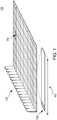
- the basic unit of a transmission in LTEis a resource block (RB) 100, which in its most common configuration consists of 12 sub-carriers 104 and 7 OFDM symbols 108 ( i.e. , one slot).
- An OFDM symbol 108may include a cyclic prefix 106.
- a unit of one sub-carrier and one OFDM symbolis referred to as a resource element (RE) 102.
- an RBmay consist of, for example, 84 REs in a 12 x 7 configuration.
- An LTE radio sub-framemay be composed of multiple resource blocks in frequency and two slots in time, with the number of RBs determining the bandwidth of the system. Two RBs in a sub-frame, that are adjacent in time, for instance as shown in FIG. 3 , may be referred to as an RB pair 300.
- An LTE communication networkmay be deployed in a number of configurations.
- a base station 502such as an eNB
- user equipment 504are in communication.
- a signalis transmitted by the eNB 502 in a downlink, i.e ., the link carrying transmissions from the eNB to the UE 504, a sub-frame may be transmitted from multiple antennas.
- the signalmay be received at a UE 504, which has one or more antennas.
- the radio channeldistorts the transmitted signals from the multiple antenna ports.
- the UE 504relies on reference symbols (RS) that are also transmitted on the downlink.
- RSreference symbols
- a reference symbolmay be understood as one or more REs carrying pre-defined symbols. These reference symbols and their position in the time-frequency grid are known, or otherwise determined, by the UE.
- the RSscan be used to determine channel estimates by measuring the effect of a specific radio channel on these symbols.
- An antenna portmay be understood as a virtual antenna, which can further be associated with a reference symbol RS.
- RSreference symbol
- the use of transmit pre-codingcan be used to direct transmitted energy towards a specific receiving UE. This may be accomplished by using all available antenna elements to transmit the same message, with different phase and/or amplitude weights applied at each antenna element. Since the reference symbol associated with each antenna port also undergoes the same pre-coding operation with identical pre-coding weights as the data, the transmission uses a single virtual antenna / single antenna port, and the UE need only perform channel estimation using a single RS.
- RSsused in LTE.
- a first type of RSis one that can be used by all UEs, and thus, have wide cell area coverage.
- One example of this type of RSis the common reference symbol (CRS) that is used by UEs for various purposes, including channel estimation.
- CRSsare defined so that they occupy certain pre-defined REs within the transmission sub-frame, regardless of whether there is any data being sent to users or not.
- a sub-frame 200may include a control region, control signaling, and reference symbols 202.
- Reference symbol 202may be a CRS used by a UE in the communication network.
- a second type of RSis a UE-specific reference symbol, which is intended specifically for use by only a certain UE or set of UEs.
- these UE-specific RSsare transmitted only when data is transmitted to a certain UE.
- the RSdoes not reach all parts of the cell, but rather only those parts of the cell where the UEs of interest (i.e ., the intended data recipients) are located.
- UE-specific RSare included as part of the RBs that are allocated to a UE for reception of user data.
- the exemplary use of UE-specific RSs in LTEis shown in the RB pair of FIG. 3 , which includes UE-specific RSs R 7 and R 9 .
- Control messages transmitted over a radio link to UEs in an LTE networkcan be broadly classified as control messages or data messages.
- Control messagesare used to facilitate the proper operation of the system, as well as proper operation of each UE within the system.
- Control messagescould include, for example, commands to control functions, such as transmitted power or other additional signaling within RBs.
- Examples of control messagesinclude, but are not limited to, the physical control format indicator channel (PCFICH) which carries configuration information of the control region size; the physical downlink control channel (PDCCH) which, for example, carries scheduling information and power control messages; the physical HARQ indicator channel (PHICH), which carries ACK/NACK in response to a previous uplink transmission; and the physical broadcast channel (PBCH), which carries system information.
- PCFICHphysical control format indicator channel
- PDCCHphysical downlink control channel
- PHICHphysical HARQ indicator channel
- PBCHphysical broadcast channel
- control messagesare demodulated using the CRS.
- the first one to four OFDM symbols, depending on the configuration, in a sub-frameare reserved for control information, for instance as shown in FIG. 2 .
- Control messages of PDCCH typeare transmitted in multiples of units called control channel elements (CCEs), where each CCE contains 36 REs.
- CCEscontrol channel elements
- data messagesmay be transmitted to users in RBs, which carry UE-specific RSs. These RSs may be used by the UEs to demodulate the data messages,
- UE-specific RSsallows a multi-antenna eNB to optimize the transmission using pre-coding of signals being transmitted from the multiple antennas so that the received signal becomes stronger at the UE and, consequently, the data rate of the transmission can be increased.
- Rel-10 of LTEalso defines a control channel called the R-PDCCH for transmitting control information to relay nodes.
- the relay node receiving the R-PDCCHcan use relay node (RN) specific reference signals to improve link performance.
- RNrelay node
- Adoption of the same principle of transmission as used for the R-PDCCHhas been considered by allowing the transmission of generic control messages to a UE using such transmissions based on UE-specific RSs.
- Section 10.1.1.7describes the transmission of data from multiple antenna ports, with a reference signal associated with each antenna port.
- US 2011/0170496discloses E-PDCCH, PDSCH and associated DMRS multiplexing.
- US2011/176634discloses an arrangement in which a Channel State Information-Reference Signal (CSI-RS) is associated with each of multiple antenna ports, and the multiple CSI-RSs are provided in a single Resource Block.
- CSI-RSChannel State Information-Reference Signal
- a problem with existing LTE systemsis that there is no effective way to transmit common control signals in a manner such that they may be demodulated using UE-specific RSs and, thus, can realize the benefits that come with using UE-specific RSs. For instance, the ability to turn them off when no data is transmitted, which could improve power efficiency and interference reduction, and allow for the number of RSs used to scale with the number of resources being used for control message transmission.
- Particular embodiments of the present inventionare directed to devices and methods for transmitting and receiving data in a wireless communications network using resource blocks that include a plurality of regions associated with one or more reference symbols.
- informationis transmitted in resource blocks (RBs) between a base station and one or more communication devices.
- RBresource blocks
- a plurality of non-overlapping regions of resource elements (REs)are defined.
- Each regionis associated with one or multiple unique reference symbols (RSs).
- UEuser equipment
- demodulates the information it receives in a particular region of an RBit uses the RS associated with that region.
- the RS informationmay be used, for example, to estimate a channel of the communication network or to demodulate and decode the data contained within the associated regions.
- a methodfor transmitting data in a resource block from a base station to a communication device.
- the transmitted resource blockincludes a plurality of regions made up of resource elements.
- the methodincludes allocating a first portion of the data to a first region of the resource block, which is associated with a first reference symbol, and allocating a second portion of the data to a second region of the resource block, which is associated with a second reference symbol.
- the methodfurther includes encoding the first portion of data to generate first encoded data and encoding the second portion of the data to generate second encoded data.
- the encoded datais modulated to generate modulated data, which is transmitted in the resource block, along with the reference symbols, to the communication device.
- a base station deviceoperable in a communication network for transmitting data in a resource block, where the resource block includes a plurality of regions made up of resource elements.
- the base stationincludes a processor configured to allocate a first portion of the data to a first region of the resource block, which is associated with a first reference symbol.
- the processoris also configured to allocate a second portion of the data to a second region of the resource block, which is associated with a second reference symbol.
- the processoris further configured to encode the first and second portions of data to generate encoded data
- the encoded datais then modulated by the processor and transmitted by a transmitter configured to transmit the modulated data, along with the first and second reference symbols, in the resource block.
- particular embodiments of the present inventionprovide a method for demodulating data in a resource block that includes a plurality of regions comprising resource elements.
- the methodincludes receiving the data at a communication device from a base station of a communication network, where a first portion of the data has been allocated to a first region of the resource block and associated with a first reference symbol, and a second portion of the data has been allocated to a second region of the resource block and associated with a second reference symbol.
- the methodalso includes estimating a first channel of the communication network using the first reference symbol and estimating a second channel of the communication network using the second reference symbol.
- the methodincludes demodulating at least one of the first or second data portions.
- Particular embodiments of the present inventionprovide a communication device operable in a communication network to receive data in a resource block, which includes a plurality of regions made up of resource elements.
- the datais received from a base station.
- a first portion of the datahas been allocated to a first region of the resource block and associated with a first reference symbol, while a second portion of the data has been allocated to a second region of the resource block and associated with a second reference symbol.
- the communication deviceincludes one or more antennas configured to receive the data, and a processor coupled to the antennas.
- the processoris configured to estimate a first channel of the communication network using the first reference symbol, and further to estimate a second channel of the communication network using the second reference symbol.
- the processoris also configured to demodulate at least one of the first or second portions of data.
- datais transmitted in resource blocks between a base station and one or more communication devices.
- FIG. 5illustrates an example wireless network 500.
- wireless network 500includes at least one base station 502 and at least one wireless user equipment (UE) communication device 504, interconnected via a network 506.
- UEwireless user equipment
- Examples of wireless UE communication devicesinclude mobile telephones, personal digital assistants, electronic readers, portable electronic tablets, personal computers, and laptop computers.
- FIG. 6illustrates a block diagram of an exemplary UE communication device 504.
- the UE communication device 504may include: an antenna array 602, which includes one or more antennas, a data processing system 606, which may include one or more microprocessors and/or one or more circuits, such as an application specific integrated circuit (ASIC), field-programmable gate arrays (FPGAs), or the like, and a data storage or memory system 608, which may include one or more non-volatile storage devices and/or one or more volatile storage devices (e.g., random access memory (RAM)).
- the antenna array 602is connected to transceiver 604, which is configured to transmit and receive signals via the antenna array 602.
- computer readable program codemay be stored in a computer readable medium, such as, but not limited to, magnetic media (e.g. , a hard disk), optical media (e.g. , a DVD), memory devices ( e.g. , random access memory), and the like.
- computer readable program codeis configured such that when executed by a processor, the code causes the data processing system 606 to perform steps described below (e.g ., steps described below with reference to the flow chart shown in FIG. 10 ).
- the UE communication device 504is configured to perform steps described above without the need for code. That is, for example, data processing system 606 may consist of one or more ASICs.
- the features described abovemay be implemented in hardware and/or software.
- the functional components of the UE communication device 504 described abovemay be implemented by data processing system 606 executing computer instructions, by data processing system 606 operating independent of any computer instructions, or by any suitable combination of hardware and/or software.
- FIG. 7illustrates a block diagram of an exemplary base station 502
- the base station 502may include: a data processing system 708, which may include one or more microprocessors and/or one or more circuits, such as an application specific integrated circuit (ASIC), field-programmable gate arrays (FPGAs), and the like; a network interface 706; and a data storage system 710, which may include one or more non-volatile storage devices and/or one or more volatile storage devices (e.g ., random access memory (RAM)),
- the network interface 706is connected to transceiver 704, which is configured to transmit and receive signals via an antenna array 702.
- the antenna arraymay be configured to include one or more antenna ports.
- antenna array 702may include a first antenna port 0, and a second antenna port 1, which correspond to ports 0 and 1 of the LTE specification.
- the base station 502is a Node B or Evolved Node B.
- computer readable program codemay be stored in a computer readable medium, such as, but not limited, to magnetic media (e.g ., a hard disk), optical media (e.g ., a DVD), memory devices ( e.g. , random access memory), and the like.
- computer readable program codeis configured such that when executed by a processor, the code causes the data processing system 708 to perform steps described below (e.g ., steps described below with reference to the flow chart shown in FIG. 8 ).
- the base station 502is configured to perform steps described above without the need for code. That is, for example, data processing system 708 may consist merely of one or more ASICs.
- the features described abovemay be implemented in hardware and/or software.
- the functional components of the base station described abovemay be implemented by data processing system 708 executing computer instructions, by data processing system 708 operating independent of any computer instructions, or by any suitable combination of hardware and/or software.
- datamay be transmitted in resource blocks (RBs) between a base station 502 and one or more communication devices 504.
- RBsresource blocks
- REsresource elements
- Each regionis associated with at least one unique reference symbol (RS).
- RS and/or antenna port informationmay be used, for example, to estimate a channel of the communication network or to demodulate the date contained within the associated regions.
- FIG. 4illustrates an exemplary resource block consisting of two time-frequency regions 402, 404, where each region has a reference symbol associated with it.
- the first region 402is associated with a first reference symbol transmitted in a resource element located in a first reference signal region 406.
- the second region 404is associated with a second reference symbol transmitted in a resource element located in a second reference signal region 408.
- Each regioncan be used, for example, to transmit control information, such as a CCE, a PHICH, or a PBCH, or fractions of such messages elements.
- the resource block 400includes multiple data regions, such as, regions 402 and 404 illustrated in FIG. 4 .
- a first portion of the datais allocated to a first region 402 of the resource block 400.
- This datais associated with a first reference symbol 406.
- the datamay be, for example, a control message.
- the control messagemay include commands related to power control scheduling information, ACK/NACK response, and/or system information.
- the first reference symbol 406may be a UE-specific reference symbol.
- a second portion of the datais allocated to a second region 404 of the resource block 400.
- This datais associated with a second reference symbol 408.
- this datamay be, for example, a control message and may include commands related to power control, scheduling information, ACK/NACK response, and/or system information.
- step 830the first portion of data is encoded to generate first encoded data.
- the second portion of the datais encoded to generate second encoded data.
- the encoded datais then modulated in step 840 to generate modulated data.
- step 850the modulated data, along with the first and second reference symbols, are transmitted in the resource block to a communication device 504.
- a base station 502such as the device diagrammed in FIG. 7 , is operable in a communications network and includes a transceiver 704 and data processing resources 708, which together are configured to transmit data in a resource block as detailed in the flow chart of FIG. 8 .
- FIG. 10a flow chart 1000 illustrating a process for demodulating data received in a resource block by a communication device 504 is shown.
- the communication device 504receives data from a base station 502 of a communication network.
- the base stationmay be, for example, an eNB as diagrammed in FiG. 7 .
- a first portion of the datais allocated to a first region of the received resource block, such as resource block 400 illustrated in FIG. 4 .
- a second portion of the datais allocated to a second region of the resource block 400.
- Each of the regionsis associated with a first and second reference symbol, respectively.
- step 1020the communication device estimates a channel of the communication network using the first reference symbol. Similarly, in step 1030, the communication device estimates a channel of the communication network using the second antenna port
- step 1040at least one of the first and second data is demodulated.
- the stepmay further include performing de-rate-matching and decoding on the demodulated data.
- a UE communication device 504such as the device diagrammed in FIG. 6 , includes an antenna array 602, a transceiver 604, and data processing resources 606, which together, are configured to demodulate data received in a resource block as detailed in the flow chart of FIG. 10 .
- a plurality of orthogonal time-frequency and code resourcesmay be defined.
- a partitionreferred to herein as a resource, may be defined as a region consisting of a subset of resource elements in the RB plus a cover code.
- the cover codemay be selected, for instance, from a set of orthogonal cover codes.
- each resourceis associated with one or more unique reference symbols, where the resource elements carrying the associated reference symbols are also transmitted in the same resource block or RB pair.
- a UEdemodulates the information in a given resource of the transmitted RB, it can use the RS associated with that resource for processing. For instance, the RS can be used for accurate channel estimation.
- each resource within the RBcan be independently assigned to one or more UEs.
- control informationis transmitted including (but not limited to) a CCE, which belongs for example to a PDCCH, a PHICH, or a PBCH. If the resource is too small to fit a whole CCE, PHICH, or PBCH, a fraction of these messages can be transmitted in a first resource and the other fractions in another resource, for instance, elsewhere in the same sub-frame.
- the other resourcecould be associated with other reference symbols.
- FIGS. 9 and 11-13illustrate exemplary partitioning of a resource block into regions along with the association of the regions to reference symbols.
- the use of an RB to illustrate embodiments in this disclosuremay straightforwardly be extended to an RB pair if, for instance, data is mapped to both slots in a sub-frame.
- the partitioning of resourcescan be performed based on frequency division multiplexing (FDM), as well as time division multiplexing (TDM) and code division multiplexing (CDM).
- FDMfrequency division multiplexing
- TDMtime division multiplexing
- CDMcode division multiplexing
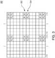
- FIG. 9shows an exemplary RB with the reference symbol positions for up to four transmission ports, as defined currently in LTE.
- the resource elements carrying the reference symbolsare denoted by R 7 and R 9 .
- the REs denoted by R 7can contain the RS for antenna port 7, or alternatively for antenna ports 7 and 8, if both ports are used.
- the RS for the two portsmay be overlaid on top of each other in a plurality of overlapping resource elements using orthogonal cover codes (OCC).
- OCCorthogonal cover codes
- the transmitted RS for port 7may be ⁇ +1, +1 ⁇ and for port. 8 may be ⁇ +1, -1 ⁇ .
- the RS for antenna ports 9 and 10are similarly overlaid on the adjacent RE pairs 904 shown in FIG. 9 .
- FIG. 9also shows two distinct regions for control message transmission within the RB.
- each regionhas 36 REs, which is the same as the number of REs in a CCE on the legacy LTE carrier.
- the first region, illustrated with dots,is associated with antenna port 7 or antenna ports 7 and 8
- the second region, illustrated with hashingis associated with port 9 or ports 9 and 10.
- a reference symbolis not necessarily transmitted in each RB transmission.
- an RS for a resourcedoes not need to be transmitted when the corresponding region is not used.
- Thisallows, for example, for the use of UE allocations and search spaces (locations where the UE performs blind decoding to search for messages addressed to it) that are defined in terms of CCEs for the legacy PDCCH, to be carried over to the control channel based on UE-specific RS.
- the only necessary change in existing schemesis the mapping of the CCEs to REs.
- the partitioning of resources within an RB or RB pair into multiple, non-overlapping regions with associated unique RSmay be implemented in various ways, for instance, as provided in FIG. 11 .
- a first regionis illustrated with dots and associated with antenna port 7 or antenna ports 7 and 8, while a second region is illustrated with hashing and associated with port 9 or ports 9 and 10.
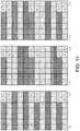
- FIG. 12illustrates two possible configurations with RBs that have been partitioned into four regions.
- no cover codes for the informationare required.
- the region illustrated with dotsis associated with antenna port 7
- the region illustrated with black blocksis associated with antenna port 8
- the region illustrated with hashingis associated with antenna port 9
- the region illustrated with white blocksis associated with antenna port 10.
- the RS for antenna ports 8 and 10may be transmitted using orthogonal cover codes in the same REs that are used by ports 7 and 9, respectively.
- Code division multiplexingmay be incorporated into a partitioning scheme to create additional associations between resources and reference symbols.
- two cover codessuch as ⁇ +1,+1 ⁇ and ⁇ +1,-1 ⁇
- ⁇ +1,+1 ⁇ and ⁇ +1,-1 ⁇could be applied to a region, e.g., the region illustrated with dots in FIGS. 9 and 11 .
- the region illustrated with dots with cover code ⁇ +1,+1 ⁇could be associated with antenna port 7 and the region illustrated with dots with cover code ⁇ +1,-1 ⁇ could be associated with antenna port 8.
- the region illustrated with hashing shown in FIGS. 9 and 11using cover code ⁇ +1,+1 ⁇ , could be associated with antenna port 9 while the region illustrated with hashing with cover code ⁇ +1,-1 ⁇ could be associated with antenna port 10.
- This approachcan provide an alternative to the implementation using four-region partitioning and RS association shown in FIG. 12 .
- a plurality of RBsmay be used together for defining region partitions and RS associations in order to embed frequency diversity into the region transmission. For instance, as shown in FIG. 13 , four regions and their associated reference symbols and antenna ports are defined using resource elements within two RBs. In this embodiment, the two RBs have frequency separation.
- the region illustrated with dotsis associated with antenna port 7.
- the region illustrated with hashingis associated with antenna port 9.
- the region illustrated with black blocksis associated with antenna port 8.
- the region illustrated with white blocksis associated with antenna port 10.
- the messagewhen a message, such as control message, is small, the message may be split and distributed over multiple regions, where each region is transmitted in a RB separated with sufficiently large frequency separation as to provide frequency diversity.
- exemplary small control messagesmay include a PDCCH with a single CCE, or a PHICH.
- a PHICHcan also share radio resources with other PDCCHs. This example is illustrated in FIG. 14 where UE 1 receives a PDCCH consisting of a single CCE and UE 2 receives a PHICH.
- the described solutionscan be applied to a new carrier type, where all sub-carriers in an RB can be utilized according to the above teachings.
- the initial, for instance first one to four depending on the configuration, OFDM symbols in a sub-framemay be reserved for control information. This is shown, for instance, in the allocation illustrated in FIG. 2 .
- the embodiments described abovecan be applied to the radio resources not allocated to the legacy control region, For instance, as shown in FIG. 14 , where the described solutions are applied to the final four OFDM symbols (after the first three for legacy operations) in the first slot of a sub-frame.
Landscapes
- Engineering & Computer Science (AREA)
- Signal Processing (AREA)
- Computer Networks & Wireless Communication (AREA)
- Mobile Radio Communication Systems (AREA)
Description
- The present invention relates generally to telecommunication networks, and more particularly, to a method and device for transmitting data in a wireless communication network.
- 3GRP Long Term Evolution (LTE) is a standard for mobile phone network technology. LTE is a set of enhancements to the Universal Mobile Telecommunications System (UMTS), and is a technology for realizing high-speed packet-based communication that can reach high data rates on both downlink and uplink channels. In LTE, transmissions are sent from base stations, such as Node Bs (NBs) and evolved Node Bs (eNBs), to mobile stations (e.g., user equipment (UE)). These transmissions are sent using orthogonal frequency division multiplexing (OFDM), which splits the signal into multiple parallel sub-carriers in frequency.
- As illustrated in
FIG. 1 , the basic unit of a transmission in LTE is a resource block (RB) 100, which in its most common configuration consists of 12sub-carriers 104 and 7 OFDM symbols 108 (i.e., one slot). AnOFDM symbol 108 may include acyclic prefix 106. A unit of one sub-carrier and one OFDM symbol is referred to as a resource element (RE) 102. Thus, an RB may consist of, for example, 84 REs in a 12 x 7 configuration. - An LTE radio sub-frame may be composed of multiple resource blocks in frequency and two slots in time, with the number of RBs determining the bandwidth of the system. Two RBs in a sub-frame, that are adjacent in time, for instance as shown in
FIG. 3 , may be referred to as anRB pair 300. In the time domain, an LTE downlink transmission may be organized into radio frames of 10 ms, each radio frame consisting of ten equally-sized sub-frames of length Tsub-frame) = 1 ms. - An LTE communication network, for instance, as illustrated in
FIG. 5 , may be deployed in a number of configurations. In certain configurations, abase station 502, such as an eNB, anduser equipment 504 are in communication. When a signal is transmitted by the eNB 502 in a downlink,i.e., the link carrying transmissions from the eNB to the UE 504, a sub-frame may be transmitted from multiple antennas. The signal may be received at a UE 504, which has one or more antennas. The radio channel distorts the transmitted signals from the multiple antenna ports. - Due to the multiple paths and conditions on each channel, in order to demodulate a transmission on the downlink, the UE 504 relies on reference symbols (RS) that are also transmitted on the downlink. A reference symbol may be understood as one or more REs carrying pre-defined symbols. These reference symbols and their position in the time-frequency grid are known, or otherwise determined, by the UE. Thus, the RSs can be used to determine channel estimates by measuring the effect of a specific radio channel on these symbols.
- According to the LTE standard, transmissions from an eNB are sent from "antenna ports" rather than antennas. An antenna port may be understood as a virtual antenna, which can further be associated with a reference symbol RS. Thus, when a UE measures the channel from an antenna port to the receiver antenna, which physical antenna elements were used for the transmission is irrelevant for the UE. The transmission on an antenna port may originate from a single physical antenna element or may be the combination of signals from multiple antenna elements.
- In certain instances, the use of transmit pre-coding can be used to direct transmitted energy towards a specific receiving UE. This may be accomplished by using all available antenna elements to transmit the same message, with different phase and/or amplitude weights applied at each antenna element. Since the reference symbol associated with each antenna port also undergoes the same pre-coding operation with identical pre-coding weights as the data, the transmission uses a single virtual antenna / single antenna port, and the UE need only perform channel estimation using a single RS.
- There are several broad types of RSs used in LTE. A first type of RS is one that can be used by all UEs, and thus, have wide cell area coverage. One example of this type of RS is the common reference symbol (CRS) that is used by UEs for various purposes, including channel estimation. Presently, these CRSs are defined so that they occupy certain pre-defined REs within the transmission sub-frame, regardless of whether there is any data being sent to users or not. For example, as shown in
FIG. 2 , a sub-frame 200 may include a control region, control signaling, andreference symbols 202.Reference symbol 202 may be a CRS used by a UE in the communication network. - A second type of RS is a UE-specific reference symbol, which is intended specifically for use by only a certain UE or set of UEs. Presently, these UE-specific RSs are transmitted only when data is transmitted to a certain UE. When pre-coded for a specific UE or set of UEs, the RS does not reach all parts of the cell, but rather only those parts of the cell where the UEs of interest (i.e., the intended data recipients) are located.
- In LTE, UE-specific RS are included as part of the RBs that are allocated to a UE for reception of user data. The exemplary use of UE-specific RSs in LTE is shown in the RB pair of
FIG. 3 , which includes UE-specific RSs R7 and R9. - Further, messages transmitted over a radio link to UEs in an LTE network can be broadly classified as control messages or data messages. Control messages are used to facilitate the proper operation of the system, as well as proper operation of each UE within the system. Control messages could include, for example, commands to control functions, such as transmitted power or other additional signaling within RBs. Examples of control messages include, but are not limited to, the physical control format indicator channel (PCFICH) which carries configuration information of the control region size; the physical downlink control channel (PDCCH) which, for example, carries scheduling information and power control messages; the physical HARQ indicator channel (PHICH), which carries ACK/NACK in response to a previous uplink transmission; and the physical broadcast channel (PBCH), which carries system information.
- In LTE Rel-10, control messages are demodulated using the CRS. The first one to four OFDM symbols, depending on the configuration, in a sub-frame are reserved for control information, for instance as shown in
FIG. 2 . Control messages of PDCCH type are transmitted in multiples of units called control channel elements (CCEs), where each CCE contains 36 REs. - Presently, data messages may be transmitted to users in RBs, which carry UE-specific RSs. These RSs may be used by the UEs to demodulate the data messages,
- The use of UE-specific RSs allows a multi-antenna eNB to optimize the transmission using pre-coding of signals being transmitted from the multiple antennas so that the received signal becomes stronger at the UE and, consequently, the data rate of the transmission can be increased.
- Similarly, Rel-10 of LTE also defines a control channel called the R-PDCCH for transmitting control information to relay nodes. The relay node receiving the R-PDCCH can use relay node (RN) specific reference signals to improve link performance. Adoption of the same principle of transmission as used for the R-PDCCH has been considered by allowing the transmission of generic control messages to a UE using such transmissions based on UE-specific RSs.
- Erik Dahlman, et al, "4G LTE/LTE-Advanced for Mobile Broadband" describes the LTE release 10 system. Section 10.1.1.7 describes the transmission of data from multiple antenna ports, with a reference signal associated with each antenna port.
US 2011/0170496 discloses E-PDCCH, PDSCH and associated DMRS multiplexing.US2011/176634 discloses an arrangement in which a Channel State Information-Reference Signal (CSI-RS) is associated with each of multiple antenna ports, and the multiple CSI-RSs are provided in a single Resource Block.- A problem with existing LTE systems is that there is no effective way to transmit common control signals in a manner such that they may be demodulated using UE-specific RSs and, thus, can realize the benefits that come with using UE-specific RSs. For instance, the ability to turn them off when no data is transmitted, which could improve power efficiency and interference reduction, and allow for the number of RSs used to scale with the number of resources being used for control message transmission.
- A further problem exists regarding how to achieve diversity for small control channel messages, such as PDCCH of a single CCE or a PHICH, when using UE specific RS transmissions.
- Also, there is not presently a way to allow transmission of control messages to UEs in bandwidths that may be different for different UEs.
- Accordingly, there is a need for a method and device for improving transmission techniques from a base station to a UE using reference symbols.
- The invention is set out in the appended claims. The references to embodiments in the description falling outside the scope of the appended claims are to be understood as mere examples which are useful for understanding the invention.
- Particular embodiments of the present invention are directed to devices and methods for transmitting and receiving data in a wireless communications network using resource blocks that include a plurality of regions associated with one or more reference symbols.
- According to certain aspects of the disclosed devices and methods, information is transmitted in resource blocks (RBs) between a base station and one or more communication devices. In each RB used for a data or control channel transmission, a plurality of non-overlapping regions of resource elements (REs) are defined. Each region is associated with one or multiple unique reference symbols (RSs). When user equipment (UE) demodulates the information it receives in a particular region of an RB, it uses the RS associated with that region. The RS information may be used, for example, to estimate a channel of the communication network or to demodulate and decode the data contained within the associated regions.
- In one particular aspect, a method is provided for transmitting data in a resource block from a base station to a communication device. The transmitted resource block includes a plurality of regions made up of resource elements. The method includes allocating a first portion of the data to a first region of the resource block, which is associated with a first reference symbol, and allocating a second portion of the data to a second region of the resource block, which is associated with a second reference symbol. The method further includes encoding the first portion of data to generate first encoded data and encoding the second portion of the data to generate second encoded data. The encoded data is modulated to generate modulated data, which is transmitted in the resource block, along with the reference symbols, to the communication device.
- Particular embodiments of the present invention provide a base station device operable in a communication network for transmitting data in a resource block, where the resource block includes a plurality of regions made up of resource elements. The base station includes a processor configured to allocate a first portion of the data to a first region of the resource block, which is associated with a first reference symbol. The processor is also configured to allocate a second portion of the data to a second region of the resource block, which is associated with a second reference symbol. The processor is further configured to encode the first and second portions of data to generate encoded data The encoded data is then modulated by the processor and transmitted by a transmitter configured to transmit the modulated data, along with the first and second reference symbols, in the resource block.
- In another aspect, particular embodiments of the present invention provide a method for demodulating data in a resource block that includes a plurality of regions comprising resource elements. The method includes receiving the data at a communication device from a base station of a communication network, where a first portion of the data has been allocated to a first region of the resource block and associated with a first reference symbol, and a second portion of the data has been allocated to a second region of the resource block and associated with a second reference symbol. The method also includes estimating a first channel of the communication network using the first reference symbol and estimating a second channel of the communication network using the second reference symbol. Finally, the method includes demodulating at least one of the first or second data portions.
- Particular embodiments of the present invention provide a communication device operable in a communication network to receive data in a resource block, which includes a plurality of regions made up of resource elements. The data is received from a base station. According to particular aspects, a first portion of the data has been allocated to a first region of the resource block and associated with a first reference symbol, while a second portion of the data has been allocated to a second region of the resource block and associated with a second reference symbol. The communication device includes one or more antennas configured to receive the data, and a processor coupled to the antennas. The processor is configured to estimate a first channel of the communication network using the first reference symbol, and further to estimate a second channel of the communication network using the second reference symbol. The processor is also configured to demodulate at least one of the first or second portions of data.
- The above and other aspects and embodiments are described below with reference to the accompanying drawings
- The accompanying drawings, which are incorporated herein and form part of the specification, illustrate various embodiments of the present disclosure and, together with the description, further serve to explain the principles of the disclosure and to enable a person skilled in the pertinent art to make and use the embodiments disclosed herein. In the drawings, like reference numbers indicate identical or functionally similar elements.
FIG. 1 illustrates an exemplary resource block.FIG. 2 illustrates an exemplary downlink sub-frame.FIG. 3 illustrates a resource block pair with UE-specific reference symbols.FIG. 4 illustrates a resource block with regions in accordance with exemplary embodiments of the present invention.- FTG. 5 illustrates a wireless communication system.
FIG. 6 is a block diagram of a UE communication device in accordance with exemplary embodiments of the present inventionFIG. 7 is a block diagram of a base station in accordance with exemplary embodiments of the present invention.FIG. 8 is a flow chart illustrating a process for transmitting data in accordance with exemplary embodiments of the present invention.FIG. 9 illustrates a resource block with regions and associated reference symbols in accordance with exemplary embodiments of the present invention.FIG. 10 is a flow chart illustrating a process for demodulating data in accordance with exemplary embodiments of the present invention.FIG. 11 illustrates exemplary resource blocks with regions and associated reference symbols in accordance with exemplary embodiments of the present invention.FIG. 12 illustrates exemplary resource blocks with four regions and associated reference symbols in accordance with exemplary embodiments of the present invention.FIG. 13 illustrates exemplary resource blocks with regions and associated reference symbols in accordance with exemplary embodiments of the present invention.FIG. 14 illustrates exemplary resource blocks with regions and associated reference symbols for transmission of small messages in accordance with exemplary embodiments of the present invention.- In exemplary embodiments of the disclosed devices and methods, data is transmitted in resource blocks between a base station and one or more communication devices.
FIG. 5 illustrates anexample wireless network 500. As shown,wireless network 500 includes at least onebase station 502 and at least one wireless user equipment (UE)communication device 504, interconnected via anetwork 506. Examples of wireless UE communication devices include mobile telephones, personal digital assistants, electronic readers, portable electronic tablets, personal computers, and laptop computers.FIG. 6 illustrates a block diagram of an exemplaryUE communication device 504. As shown inFIG. 6 , theUE communication device 504 may include: anantenna array 602, which includes one or more antennas, adata processing system 606, which may include one or more microprocessors and/or one or more circuits, such as an application specific integrated circuit (ASIC), field-programmable gate arrays (FPGAs), or the like, and a data storage ormemory system 608, which may include one or more non-volatile storage devices and/or one or more volatile storage devices (e.g., random access memory (RAM)). Theantenna array 602 is connected totransceiver 604, which is configured to transmit and receive signals via theantenna array 602.- In embodiments where
data processing system 606 includes a microprocessor, computer readable program code may be stored in a computer readable medium, such as, but not limited to, magnetic media (e.g., a hard disk), optical media (e.g., a DVD), memory devices (e.g., random access memory), and the like. In some embodiments, computer readable program code is configured such that when executed by a processor, the code causes thedata processing system 606 to perform steps described below (e.g., steps described below with reference to the flow chart shown inFIG. 10 ). In other embodiments, theUE communication device 504 is configured to perform steps described above without the need for code. That is, for example,data processing system 606 may consist of one or more ASICs. Hence, the features described above may be implemented in hardware and/or software. For example, in particular embodiments, the functional components of theUE communication device 504 described above may be implemented bydata processing system 606 executing computer instructions, bydata processing system 606 operating independent of any computer instructions, or by any suitable combination of hardware and/or software. FIG. 7 illustrates a block diagram of anexemplary base station 502, As shown inFIG. 7 , thebase station 502 may include: adata processing system 708, which may include one or more microprocessors and/or one or more circuits, such as an application specific integrated circuit (ASIC), field-programmable gate arrays (FPGAs), and the like; anetwork interface 706; and adata storage system 710, which may include one or more non-volatile storage devices and/or one or more volatile storage devices (e.g., random access memory (RAM)), Thenetwork interface 706 is connected totransceiver 704, which is configured to transmit and receive signals via anantenna array 702. According to particular embodiments of the present invention, the antenna array may be configured to include one or more antenna ports. For instance,antenna array 702 may include afirst antenna port 0, and asecond antenna port 1, which correspond toports base station 502 is a Node B or Evolved Node B.- In embodiments where
data processing system 708 includes a microprocessor, computer readable program code may be stored in a computer readable medium, such as, but not limited, to magnetic media (e.g., a hard disk), optical media (e.g., a DVD), memory devices (e.g., random access memory), and the like. In some embodiments, computer readable program code is configured such that when executed by a processor, the code causes thedata processing system 708 to perform steps described below (e.g., steps described below with reference to the flow chart shown inFIG. 8 ). In other embodiments, thebase station 502 is configured to perform steps described above without the need for code. That is, for example,data processing system 708 may consist merely of one or more ASICs. Hence, the features described above may be implemented in hardware and/or software. For example, in particular embodiments, the functional components of the base station described above may be implemented bydata processing system 708 executing computer instructions, bydata processing system 708 operating independent of any computer instructions, or by any suitable combination of hardware and/or software. - According to particular embodiments of the present invention, data may be transmitted in resource blocks (RBs) between a
base station 502 and one ormore communication devices 504. In certain aspects, within each RB used for a data or control channel transmission a plurality of non-overiapping regions of resource elements (REs) are defined. Each region is associated with at least one unique reference symbol (RS). - When
user equipment 504 demodulates the information it receives in a particular region of an RB, it uses the RS and/or antenna port associated with that region. The RS and/or antenna port information may be used, for example, to estimate a channel of the communication network or to demodulate the date contained within the associated regions. FIG. 4 illustrates an exemplary resource block consisting of two time-frequency regions first region 402 is associated with a first reference symbol transmitted in a resource element located in a firstreference signal region 406. Thesecond region 404 is associated with a second reference symbol transmitted in a resource element located in a secondreference signal region 408. Each region can be used, for example, to transmit control information, such as a CCE, a PHICH, or a PBCH, or fractions of such messages elements.- Referring now to
FIG. 8 , aflow chart 800 illustrating a process for transmitting data in aresource block 400 from abase station 502 to acommunication device 504 is shown. Theresource block 400 includes multiple data regions, such as,regions FIG. 4 . - In the first step of the
process 810, a first portion of the data is allocated to afirst region 402 of theresource block 400. This data is associated with afirst reference symbol 406. The data may be, for example, a control message. According to aspects of the embodiment, the control message may include commands related to power control scheduling information, ACK/NACK response, and/or system information. Furthermore, thefirst reference symbol 406 may be a UE-specific reference symbol. - In
step 820, a second portion of the data is allocated to asecond region 404 of theresource block 400. This data is associated with asecond reference symbol 408. As with the first data, this data may be, for example, a control message and may include commands related to power control, scheduling information, ACK/NACK response, and/or system information. - In
step 830, the first portion of data is encoded to generate first encoded data. Similarly, the second portion of the data is encoded to generate second encoded data. The encoded data is then modulated instep 840 to generate modulated data. - In
step 850, the modulated data, along with the first and second reference symbols, are transmitted in the resource block to acommunication device 504. - According to particular embodiments of the present invention, a
base station 502, such as the device diagrammed inFIG. 7 , is operable in a communications network and includes atransceiver 704 anddata processing resources 708, which together are configured to transmit data in a resource block as detailed in the flow chart ofFIG. 8 . - Referring to
FIG. 10 , aflow chart 1000 illustrating a process for demodulating data received in a resource block by acommunication device 504 is shown. - In
step 1010, thecommunication device 504 receives data from abase station 502 of a communication network. The base station may be, for example, an eNB as diagrammed inFiG. 7 . - A first portion of the data is allocated to a first region of the received resource block, such as
resource block 400 illustrated inFIG. 4 . A second portion of the data is allocated to a second region of theresource block 400. Each of the regions is associated with a first and second reference symbol, respectively. - In
step 1020, the communication device estimates a channel of the communication network using the first reference symbol. Similarly, instep 1030, the communication device estimates a channel of the communication network using the second antenna port - In
step 1040, at least one of the first and second data is demodulated, The step may further include performing de-rate-matching and decoding on the demodulated data. - According to particular embodiments of the present invention, a
UE communication device 504, such as the device diagrammed inFIG. 6 , includes anantenna array 602, atransceiver 604, anddata processing resources 606, which together, are configured to demodulate data received in a resource block as detailed in the flow chart ofFIG. 10 . - According to particular embodiments of the present invention, in a RB used for control channel transmission, a plurality of orthogonal time-frequency and code resources may be defined. A partition, referred to herein as a resource, may be defined as a region consisting of a subset of resource elements in the RB plus a cover code. The cover code may be selected, for instance, from a set of orthogonal cover codes. According to particular embodiments of the present invention, each resource is associated with one or more unique reference symbols, where the resource elements carrying the associated reference symbols are also transmitted in the same resource block or RB pair. When a UE demodulates the information in a given resource of the transmitted RB, it can use the RS associated with that resource for processing. For instance, the RS can be used for accurate channel estimation. Furthermore, each resource within the RB can be independently assigned to one or more UEs.
- In certain aspects, within each resource, control information is transmitted including (but not limited to) a CCE, which belongs for example to a PDCCH, a PHICH, or a PBCH. If the resource is too small to fit a whole CCE, PHICH, or PBCH, a fraction of these messages can be transmitted in a first resource and the other fractions in another resource, for instance, elsewhere in the same sub-frame. The other resource could be associated with other reference symbols.
FIGS. 9 and11-13 illustrate exemplary partitioning of a resource block into regions along with the association of the regions to reference symbols. The use of an RB to illustrate embodiments in this disclosure may straightforwardly be extended to an RB pair if, for instance, data is mapped to both slots in a sub-frame. According to particular embodiments of the present invention, the partitioning of resources can be performed based on frequency division multiplexing (FDM), as well as time division multiplexing (TDM) and code division multiplexing (CDM).FIG. 9 shows an exemplary RB with the reference symbol positions for up to four transmission ports, as defined currently in LTE. The resource elements carrying the reference symbols are denoted byR7 andR9. The REs denoted byR7 can contain the RS for antenna port 7, or alternatively for antenna ports 7 and 8, if both ports are used. The RS for the two ports may be overlaid on top of each other in a plurality of overlapping resource elements using orthogonal cover codes (OCC). For example, in each pair ofadjacent symbols 902 shown inFIG. 9 , the transmitted RS for port 7 may be {+1, +1} and for port. 8 may be {+1, -1}. According to particular embodiments of the present invention, the RS for antenna ports 9 and 10 are similarly overlaid on the adjacent RE pairs 904 shown inFIG. 9 .FIG. 9 also shows two distinct regions for control message transmission within the RB. In this embodiment, each region has 36 REs, which is the same as the number of REs in a CCE on the legacy LTE carrier. The first region, illustrated with dots, is associated with antenna port 7 or antenna ports 7 and 8, whereas the second region, illustrated with hashing, is associated with port 9 or ports 9 and 10.- According to particular embodiments of the present invention, a reference symbol is not necessarily transmitted in each RB transmission. For instance, an RS for a resource does not need to be transmitted when the corresponding region is not used. This allows, for example, for the use of UE allocations and search spaces (locations where the UE performs blind decoding to search for messages addressed to it) that are defined in terms of CCEs for the legacy PDCCH, to be carried over to the control channel based on UE-specific RS. The only necessary change in existing schemes is the mapping of the CCEs to REs.
- In particular embodiments of the present invention, the partitioning of resources within an RB or RB pair into multiple, non-overlapping regions with associated unique RS may be implemented in various ways, for instance, as provided in
FIG. 11 . In the examples ofFIG. 11 , a first region is illustrated with dots and associated with antenna port 7 or antenna ports 7 and 8, while a second region is illustrated with hashing and associated with port 9 or ports 9 and 10. - A further example, shown in
FIG. 12 , illustrates two possible configurations with RBs that have been partitioned into four regions. According to this example, no cover codes for the information are required. Thus, the region illustrated with dots is associated with antenna port 7, the region illustrated with black blocks is associated with antenna port 8, the region illustrated with hashing is associated with antenna port 9, and the region illustrated with white blocks is associated with antenna port 10. As previously described, the RS for antenna ports 8 and 10 may be transmitted using orthogonal cover codes in the same REs that are used by ports 7 and 9, respectively. - Code division multiplexing (CDM) may be incorporated into a partitioning scheme to create additional associations between resources and reference symbols. For instance, two cover codes, such as {+1,+1} and {+1,-1}, could be applied to a region, e.g., the region illustrated with dots in
FIGS. 9 and11 . In this example, the region illustrated with dots with cover code {+1,+1} could be associated with antenna port 7 and the region illustrated with dots with cover code {+1,-1} could be associated with antenna port 8. Similarly, the region illustrated with hashing shown inFIGS. 9 and11 , using cover code {+1,+1}, could be associated with antenna port 9 while the region illustrated with hashing with cover code {+1,-1} could be associated with antenna port 10. This approach can provide an alternative to the implementation using four-region partitioning and RS association shown inFIG. 12 . - According to certain embodiments, a plurality of RBs may be used together for defining region partitions and RS associations in order to embed frequency diversity into the region transmission. For instance, as shown in
FIG. 13 , four regions and their associated reference symbols and antenna ports are defined using resource elements within two RBs. In this embodiment, the two RBs have frequency separation. The region illustrated with dots is associated with antenna port 7. The region illustrated with hashing is associated with antenna port 9. The region illustrated with black blocks is associated with antenna port 8. The region illustrated with white blocks is associated with antenna port 10. - According to certain embodiments of the present invention, when a message, such as control message, is small, the message may be split and distributed over multiple regions, where each region is transmitted in a RB separated with sufficiently large frequency separation as to provide frequency diversity. Exemplary small control messages may include a PDCCH with a single CCE, or a PHICH.
- As discussed above, different orthogonal resources within a RB can be utilized by different PDCCHs. A PHICH can also share radio resources with other PDCCHs. This example is illustrated in
FIG. 14 whereUE 1 receives a PDCCH consisting of a single CCE andUE 2 receives a PHICH. - The described solutions cart be applied to a new carrier type, where all sub-carriers in an RB can be utilized according to the above teachings. However, in a carrier that is backward compatible to existing LTE system specifications, the initial, for instance first one to four depending on the configuration, OFDM symbols in a sub-frame may be reserved for control information. This is shown, for instance, in the allocation illustrated in
FIG. 2 . To enable support of legacy UEs within a cell, the embodiments described above can be applied to the radio resources not allocated to the legacy control region, For instance, as shown inFIG. 14 , where the described solutions are applied to the final four OFDM symbols (after the first three for legacy operations) in the first slot of a sub-frame. - Additionally, while the processes described above and illustrated in the drawings are shown as a sequence of steps, this was done solely for the sake of illustration. Accordingly, it is contemplated that some steps may be added, some steps may be omitted, the order of the steps may be re-arranged, and some steps may be performed in parallel.
Claims (14)
- A method for transmitting data in a resource block from a base station (502) to a communication device (504), the resource block including a plurality of regions that comprise resource elements, comprising:allocating (810) a first portion of said data to a first region of said plurality of regions, wherein said first portion of said data is associated with a first reference symbol;allocating (820) a second portion of said data to a second region of said plurality of regions, wherein said second portion of said data is associated with a second reference symbol;encoding (830) said first and second portions of said data to generate first and second encoded data;modulating (840) said first and second encoded data to generate modulated data; andtransmitting (850) said modulated data and said first and second reference symbols in said resource block, to said communication device,characterised by:allocating a third portion of said data to said first region, wherein said third portion of said data is associated with a third reference symbol; andapplying orthogonal cover codes to said first and third reference symbols, wherein said first and third reference symbols are allocated to an overlapping plurality of resource elements of said resource block.
- The method according to claim 1, wherein said first portion of said data is a control message.
- The method according to claim 2, wherein said control message includes commands related to one or more of power control, scheduling information, ACK/NACK response and system information.
- The method according to claim 2 or 3, wherein said first reference symbol is a UE-specific reference symbol.
- The method according to any of claims 1-4, wherein said first reference symbol is uniquely associated with said communication device.
- The method of according to any of claims 1-5, wherein said second reference symbol is not associated with said communication device.
- The method according to any preceding claim, further comprising:applying orthogonal cover codes to said first and third portions of said data.
- The method according to claim 1, wherein said resource block is comprised of a plurality of orthogonal frequency division multiplexed (OFDM) symbols, and further comprising:allocating a control message to a subset of said OFDM symbols to form a third region.
- A base station device (502) operable in a communication network for transmitting data in a resource block, the resource block including a plurality of regions that comprise resource elements, comprising:a processor (708) configured to perform a method as claimed in any of claims 1-8.
- A method for demodulating data in a resource block, which includes a plurality of regions that comprise resource elements, comprising:receiving (1010) said data at a communication device from a base station of a communication network, wherein a first portion of said data is allocated to a first region of said plurality of regions and is associated with a first reference symbol, a second portion of said data is allocated to a second region of said plurality of regions and is associated with a second reference symbol, a third portion of said data is allocated to said first region and is associated with a third reference symbol, said first and third reference symbols are allocated to an overlapping plurality of resource elements of said resource block, and orthogonal cover codes are applied to said first and third reference symbols;estimating (1020) a first channel of said communication network using said first reference symbol;estimating (1030) a second channel of said communication network using said second reference symbol; anddemodulating (1040) at least one of said first and second portions of said data.
- The method according to claim 10, wherein said first portion of said data is a control message.
- The method according to claim 11, wherein said control message includes commands related to one or more of power control, scheduling information, ACK/NACK response and system information.
- The method according to any of claims 10-12, wherein said first reference symbol is uniquely associated with said communication device.
- A communication device (504) operable in a communication network to receive data in a resource block, which includes a plurality of regions that comprise resource elements, comprising:an antenna (602) configured to receive said data; anda processor (606) coupled to said antenna and configured to receive said data from said antenna;wherein, a first portion of said data is allocated to a first region of said plurality of regions and is associated with a first reference symbol and a second portion of said data is allocated to a second region of said plurality of regions and is associated with a second reference symbol, a third portion of said data is allocated to said first region and is associated with a third reference symbol, said first and third reference symbols are allocated to an overlapping plurality of resource elements of said resource block, and orthogonal cover codes are applied to said first and third reference symbols, and said processor is further configured to perform a method according to any of claims 10 to 13.
Applications Claiming Priority (3)
| Application Number | Priority Date | Filing Date | Title |
|---|---|---|---|
| US201161523540P | 2011-08-15 | 2011-08-15 | |
| US13/494,040US9780931B2 (en) | 2011-08-15 | 2012-06-12 | Flexible transmission of messages in a wireless communication system |
| PCT/IB2012/054141WO2013024434A1 (en) | 2011-08-15 | 2012-08-14 | Flexible transmission of messages in a wireless communication system |
Publications (2)
| Publication Number | Publication Date |
|---|---|
| EP2745482A1 EP2745482A1 (en) | 2014-06-25 |
| EP2745482B1true EP2745482B1 (en) | 2019-02-13 |
Family
ID=47712660
Family Applications (1)
| Application Number | Title | Priority Date | Filing Date |
|---|---|---|---|
| EP12770236.3ANot-in-forceEP2745482B1 (en) | 2011-08-15 | 2012-08-14 | Flexible transmission of messages in a wireless communication system |
Country Status (5)
| Country | Link |
|---|---|
| US (1) | US9780931B2 (en) |
| EP (1) | EP2745482B1 (en) |
| JP (1) | JP5969609B2 (en) |
| CN (1) | CN103858401B (en) |
| WO (1) | WO2013024434A1 (en) |
Families Citing this family (6)
| Publication number | Priority date | Publication date | Assignee | Title |
|---|---|---|---|---|
| US9900131B2 (en) | 2011-08-15 | 2018-02-20 | Telefonaktiebolaget Lm Ericsson (Publ) | Flexible transmission of messages in a wireless communication system with multiple transmit antennas |
| US9780931B2 (en) | 2011-08-15 | 2017-10-03 | Telefonaktiebolaget Lm Ericsson (Publ) | Flexible transmission of messages in a wireless communication system |
| US8982814B2 (en) | 2011-11-04 | 2015-03-17 | Telefonaktiebolaget L M Ericsson (Publ) | Network node, user equipment and methods therein |
| CN105812106B (en)* | 2014-12-31 | 2019-05-24 | 华为技术有限公司 | The method and apparatus for transmitting upstream data |
| CN107925533B (en)* | 2015-09-24 | 2022-06-17 | 苹果公司 | V2X performance enhancement in high speed environments |
| GB2566306B (en)* | 2017-09-08 | 2021-06-16 | Samsung Electronics Co Ltd | Phase tracking reference signal |
Citations (1)
| Publication number | Priority date | Publication date | Assignee | Title |
|---|---|---|---|---|
| US20110170496A1 (en)* | 2010-01-11 | 2011-07-14 | Research In Motion Limited | Control Channel Interference Management and Extended PDCCH for Heterogeneous Network |
Family Cites Families (17)
| Publication number | Priority date | Publication date | Assignee | Title |
|---|---|---|---|---|
| WO2007132861A1 (en)* | 2006-05-16 | 2007-11-22 | Sharp Kabushiki Kaisha | Mobile communication system, mobile station apparatus, base station apparatus and mobile communication method |
| JP4671982B2 (en)* | 2007-01-09 | 2011-04-20 | 株式会社エヌ・ティ・ティ・ドコモ | Base station, transmission method and mobile communication system |
| CN101227739B (en) | 2008-02-02 | 2011-12-07 | 中兴通讯股份有限公司 | Distribution method of physics commingle retransmission indicating channel resource |
| CN101610104B (en)* | 2008-06-19 | 2013-03-13 | 电信科学技术研究院 | Method and device for distributing power of user dedicated reference symbols |
| KR20100089758A (en) | 2009-02-04 | 2010-08-12 | 엘지전자 주식회사 | Apparatus and method of transmitting signal in wireless communication system |
| JP5059800B2 (en) | 2009-03-16 | 2012-10-31 | 株式会社エヌ・ティ・ティ・ドコモ | Radio base station apparatus, mobile station apparatus, and radio communication method |
| RU2557164C2 (en) | 2009-10-01 | 2015-07-20 | Интердиджитал Пэйтент Холдингз, Инк. | Uplink control data transmission |
| KR101789326B1 (en)* | 2009-10-21 | 2017-10-24 | 엘지전자 주식회사 | Method and apparatus of transmitting reference signal in wireless communication system including relay node |
| WO2011079454A1 (en) | 2009-12-31 | 2011-07-07 | Nokia Corporation | Overlapping resource signaling via code switching |
| KR101740221B1 (en)* | 2010-01-18 | 2017-05-29 | 주식회사 골드피크이노베이션즈 | Method and Apparatus for allocating Channel State Information-Reference Signal in wireless communication system |
| KR101673906B1 (en) | 2010-04-29 | 2016-11-22 | 삼성전자주식회사 | Method and apparatus for mapping of ack/nack channel for supporting sdma downlink control channel in ofdm system |
| US8654734B2 (en) | 2010-06-01 | 2014-02-18 | Texas Instruments Incorporated | Multi-cell channel state information-reference symbol patterns for long term evolution extended cyclic prefix and code division multiplexing-time multiplexing |
| US8509155B2 (en) | 2010-07-16 | 2013-08-13 | Samsung Electronics Co., Ltd. | Method and system for multiplexing acknowledgement signals and sounding reference signals |
| WO2012026742A2 (en) | 2010-08-23 | 2012-03-01 | 엘지전자 주식회사 | Method and apparatus for transceiving a precoded signal in a multiple antenna supported wireless communication system |
| US20120263117A1 (en) | 2011-04-13 | 2012-10-18 | Motorola Mobility, Inc. | Method and Apparatus to Adjust the Control Region of a Subframe for Reducing Interference Between Channels in Wireless Communication Systems |
| US20130003604A1 (en) | 2011-06-30 | 2013-01-03 | Research In Motion Limited | Method and Apparatus for Enhancing Downlink Control Information Transmission |
| US9780931B2 (en) | 2011-08-15 | 2017-10-03 | Telefonaktiebolaget Lm Ericsson (Publ) | Flexible transmission of messages in a wireless communication system |
- 2012
- 2012-06-12USUS13/494,040patent/US9780931B2/enactiveActive
- 2012-08-14JPJP2014525547Apatent/JP5969609B2/ennot_activeExpired - Fee Related
- 2012-08-14EPEP12770236.3Apatent/EP2745482B1/ennot_activeNot-in-force
- 2012-08-14WOPCT/IB2012/054141patent/WO2013024434A1/enactiveApplication Filing
- 2012-08-14CNCN201280050682.6Apatent/CN103858401B/ennot_activeExpired - Fee Related
Patent Citations (1)
| Publication number | Priority date | Publication date | Assignee | Title |
|---|---|---|---|---|
| US20110170496A1 (en)* | 2010-01-11 | 2011-07-14 | Research In Motion Limited | Control Channel Interference Management and Extended PDCCH for Heterogeneous Network |
Also Published As
| Publication number | Publication date |
|---|---|
| US9780931B2 (en) | 2017-10-03 |
| CN103858401B (en) | 2017-08-22 |
| EP2745482A1 (en) | 2014-06-25 |
| CN103858401A (en) | 2014-06-11 |
| JP5969609B2 (en) | 2016-08-17 |
| WO2013024434A1 (en) | 2013-02-21 |
| JP2014524703A (en) | 2014-09-22 |
| HK1198851A1 (en) | 2015-06-12 |
| US20130044834A1 (en) | 2013-02-21 |
Similar Documents
| Publication | Publication Date | Title |
|---|---|---|
| US10735165B2 (en) | Flexible transmission of messages in a wireless communication system with multiple transmit antennas | |
| CN115426086B (en) | Method and apparatus for configuring demodulation reference signal location in a wireless cellular communication system | |
| KR101701899B1 (en) | 8-transmit antenna reference signal design for downlink communications in a wireless system | |
| CN105141405B (en) | Resource mapping method and device for OFDM system | |
| US11290246B2 (en) | DMRS indication method, terminal, and base station | |
| CN103039031B (en) | Method for performing HARQ processing and device using the method | |
| EP2369776B1 (en) | Method for indicating a DM-RS antenna port in a wireless communication system | |
| CN103650367B (en) | Base station, terminal, communication system, communication method, and integrated circuit | |
| JP6229987B2 (en) | Base station apparatus, communication method, and integrated circuit | |
| EP2639994B1 (en) | Method and apparatus for transmitting/receiving control channel in wireless communication system | |
| CN104272642A (en) | Resource Aggregation in Enhanced Control Channel | |
| EP2745482B1 (en) | Flexible transmission of messages in a wireless communication system | |
| CN103997722A (en) | Method and system for demodulation reference signal | |
| KR20110127051A (en) | Apparatus and method for processing channel state measurement reference signal in wireless communication system | |
| HK1198851B (en) | Flexible transmission of messages in a wireless communication system | |
| HK1198852B (en) | Flexible transmission of messages in a wireless communication system with multiple transmit antennas |
Legal Events
| Date | Code | Title | Description |
|---|---|---|---|
| PUAI | Public reference made under article 153(3) epc to a published international application that has entered the european phase | Free format text:ORIGINAL CODE: 0009012 | |
| 17P | Request for examination filed | Effective date:20140219 | |
| AK | Designated contracting states | Kind code of ref document:A1 Designated state(s):AL AT BE BG CH CY CZ DE DK EE ES FI FR GB GR HR HU IE IS IT LI LT LU LV MC MK MT NL NO PL PT RO RS SE SI SK SM TR | |
| DAX | Request for extension of the european patent (deleted) | ||
| STAA | Information on the status of an ep patent application or granted ep patent | Free format text:STATUS: EXAMINATION IS IN PROGRESS | |
| 17Q | First examination report despatched | Effective date:20170828 | |
| REG | Reference to a national code | Ref country code:DE Ref legal event code:R079 Ref document number:602012056650 Country of ref document:DE Free format text:PREVIOUS MAIN CLASS: H04L0027260000 Ipc:H04L0005000000 | |
| GRAP | Despatch of communication of intention to grant a patent | Free format text:ORIGINAL CODE: EPIDOSNIGR1 | |
| STAA | Information on the status of an ep patent application or granted ep patent | Free format text:STATUS: GRANT OF PATENT IS INTENDED | |
| RIC1 | Information provided on ipc code assigned before grant | Ipc:H04L 27/26 20060101ALN20180831BHEP Ipc:H04L 5/00 20060101AFI20180831BHEP | |
| INTG | Intention to grant announced | Effective date:20180924 | |
| GRAS | Grant fee paid | Free format text:ORIGINAL CODE: EPIDOSNIGR3 | |
| GRAA | (expected) grant | Free format text:ORIGINAL CODE: 0009210 | |
| STAA | Information on the status of an ep patent application or granted ep patent | Free format text:STATUS: THE PATENT HAS BEEN GRANTED | |
| AK | Designated contracting states | Kind code of ref document:B1 Designated state(s):AL AT BE BG CH CY CZ DE DK EE ES FI FR GB GR HR HU IE IS IT LI LT LU LV MC MK MT NL NO PL PT RO RS SE SI SK SM TR | |
| REG | Reference to a national code | Ref country code:GB Ref legal event code:FG4D | |
| REG | Reference to a national code | Ref country code:CH Ref legal event code:EP Ref country code:AT Ref legal event code:REF Ref document number:1096827 Country of ref document:AT Kind code of ref document:T Effective date:20190215 | |
| REG | Reference to a national code | Ref country code:IE Ref legal event code:FG4D | |
| REG | Reference to a national code | Ref country code:DE Ref legal event code:R096 Ref document number:602012056650 Country of ref document:DE | |
| REG | Reference to a national code | Ref country code:LT Ref legal event code:MG4D | |
| REG | Reference to a national code | Ref country code:NL Ref legal event code:MP Effective date:20190213 | |
| PG25 | Lapsed in a contracting state [announced via postgrant information from national office to epo] | Ref country code:FI Free format text:LAPSE BECAUSE OF FAILURE TO SUBMIT A TRANSLATION OF THE DESCRIPTION OR TO PAY THE FEE WITHIN THE PRESCRIBED TIME-LIMIT Effective date:20190213 Ref country code:LT Free format text:LAPSE BECAUSE OF FAILURE TO SUBMIT A TRANSLATION OF THE DESCRIPTION OR TO PAY THE FEE WITHIN THE PRESCRIBED TIME-LIMIT Effective date:20190213 Ref country code:NL Free format text:LAPSE BECAUSE OF FAILURE TO SUBMIT A TRANSLATION OF THE DESCRIPTION OR TO PAY THE FEE WITHIN THE PRESCRIBED TIME-LIMIT Effective date:20190213 Ref country code:NO Free format text:LAPSE BECAUSE OF FAILURE TO SUBMIT A TRANSLATION OF THE DESCRIPTION OR TO PAY THE FEE WITHIN THE PRESCRIBED TIME-LIMIT Effective date:20190513 Ref country code:PT Free format text:LAPSE BECAUSE OF FAILURE TO SUBMIT A TRANSLATION OF THE DESCRIPTION OR TO PAY THE FEE WITHIN THE PRESCRIBED TIME-LIMIT Effective date:20190613 Ref country code:SE Free format text:LAPSE BECAUSE OF FAILURE TO SUBMIT A TRANSLATION OF THE DESCRIPTION OR TO PAY THE FEE WITHIN THE PRESCRIBED TIME-LIMIT Effective date:20190213 | |
| PG25 | Lapsed in a contracting state [announced via postgrant information from national office to epo] | Ref country code:RS Free format text:LAPSE BECAUSE OF FAILURE TO SUBMIT A TRANSLATION OF THE DESCRIPTION OR TO PAY THE FEE WITHIN THE PRESCRIBED TIME-LIMIT Effective date:20190213 Ref country code:HR Free format text:LAPSE BECAUSE OF FAILURE TO SUBMIT A TRANSLATION OF THE DESCRIPTION OR TO PAY THE FEE WITHIN THE PRESCRIBED TIME-LIMIT Effective date:20190213 Ref country code:GR Free format text:LAPSE BECAUSE OF FAILURE TO SUBMIT A TRANSLATION OF THE DESCRIPTION OR TO PAY THE FEE WITHIN THE PRESCRIBED TIME-LIMIT Effective date:20190514 Ref country code:LV Free format text:LAPSE BECAUSE OF FAILURE TO SUBMIT A TRANSLATION OF THE DESCRIPTION OR TO PAY THE FEE WITHIN THE PRESCRIBED TIME-LIMIT Effective date:20190213 Ref country code:IS Free format text:LAPSE BECAUSE OF FAILURE TO SUBMIT A TRANSLATION OF THE DESCRIPTION OR TO PAY THE FEE WITHIN THE PRESCRIBED TIME-LIMIT Effective date:20190613 Ref country code:BG Free format text:LAPSE BECAUSE OF FAILURE TO SUBMIT A TRANSLATION OF THE DESCRIPTION OR TO PAY THE FEE WITHIN THE PRESCRIBED TIME-LIMIT Effective date:20190513 | |
| REG | Reference to a national code | Ref country code:AT Ref legal event code:MK05 Ref document number:1096827 Country of ref document:AT Kind code of ref document:T Effective date:20190213 | |
| PG25 | Lapsed in a contracting state [announced via postgrant information from national office to epo] | Ref country code:EE Free format text:LAPSE BECAUSE OF FAILURE TO SUBMIT A TRANSLATION OF THE DESCRIPTION OR TO PAY THE FEE WITHIN THE PRESCRIBED TIME-LIMIT Effective date:20190213 Ref country code:ES Free format text:LAPSE BECAUSE OF FAILURE TO SUBMIT A TRANSLATION OF THE DESCRIPTION OR TO PAY THE FEE WITHIN THE PRESCRIBED TIME-LIMIT Effective date:20190213 Ref country code:CZ Free format text:LAPSE BECAUSE OF FAILURE TO SUBMIT A TRANSLATION OF THE DESCRIPTION OR TO PAY THE FEE WITHIN THE PRESCRIBED TIME-LIMIT Effective date:20190213 Ref country code:AL Free format text:LAPSE BECAUSE OF FAILURE TO SUBMIT A TRANSLATION OF THE DESCRIPTION OR TO PAY THE FEE WITHIN THE PRESCRIBED TIME-LIMIT Effective date:20190213 Ref country code:RO Free format text:LAPSE BECAUSE OF FAILURE TO SUBMIT A TRANSLATION OF THE DESCRIPTION OR TO PAY THE FEE WITHIN THE PRESCRIBED TIME-LIMIT Effective date:20190213 Ref country code:SK Free format text:LAPSE BECAUSE OF FAILURE TO SUBMIT A TRANSLATION OF THE DESCRIPTION OR TO PAY THE FEE WITHIN THE PRESCRIBED TIME-LIMIT Effective date:20190213 Ref country code:IT Free format text:LAPSE BECAUSE OF FAILURE TO SUBMIT A TRANSLATION OF THE DESCRIPTION OR TO PAY THE FEE WITHIN THE PRESCRIBED TIME-LIMIT Effective date:20190213 Ref country code:DK Free format text:LAPSE BECAUSE OF FAILURE TO SUBMIT A TRANSLATION OF THE DESCRIPTION OR TO PAY THE FEE WITHIN THE PRESCRIBED TIME-LIMIT Effective date:20190213 | |
| REG | Reference to a national code | Ref country code:DE Ref legal event code:R097 Ref document number:602012056650 Country of ref document:DE | |
| PG25 | Lapsed in a contracting state [announced via postgrant information from national office to epo] | Ref country code:SM Free format text:LAPSE BECAUSE OF FAILURE TO SUBMIT A TRANSLATION OF THE DESCRIPTION OR TO PAY THE FEE WITHIN THE PRESCRIBED TIME-LIMIT Effective date:20190213 Ref country code:PL Free format text:LAPSE BECAUSE OF FAILURE TO SUBMIT A TRANSLATION OF THE DESCRIPTION OR TO PAY THE FEE WITHIN THE PRESCRIBED TIME-LIMIT Effective date:20190213 | |
| PLBE | No opposition filed within time limit | Free format text:ORIGINAL CODE: 0009261 | |
| STAA | Information on the status of an ep patent application or granted ep patent | Free format text:STATUS: NO OPPOSITION FILED WITHIN TIME LIMIT | |
| PG25 | Lapsed in a contracting state [announced via postgrant information from national office to epo] | Ref country code:AT Free format text:LAPSE BECAUSE OF FAILURE TO SUBMIT A TRANSLATION OF THE DESCRIPTION OR TO PAY THE FEE WITHIN THE PRESCRIBED TIME-LIMIT Effective date:20190213 | |
| 26N | No opposition filed | Effective date:20191114 | |
| PG25 | Lapsed in a contracting state [announced via postgrant information from national office to epo] | Ref country code:SI Free format text:LAPSE BECAUSE OF FAILURE TO SUBMIT A TRANSLATION OF THE DESCRIPTION OR TO PAY THE FEE WITHIN THE PRESCRIBED TIME-LIMIT Effective date:20190213 | |
| PG25 | Lapsed in a contracting state [announced via postgrant information from national office to epo] | Ref country code:TR Free format text:LAPSE BECAUSE OF FAILURE TO SUBMIT A TRANSLATION OF THE DESCRIPTION OR TO PAY THE FEE WITHIN THE PRESCRIBED TIME-LIMIT Effective date:20190213 | |
| PG25 | Lapsed in a contracting state [announced via postgrant information from national office to epo] | Ref country code:MC Free format text:LAPSE BECAUSE OF FAILURE TO SUBMIT A TRANSLATION OF THE DESCRIPTION OR TO PAY THE FEE WITHIN THE PRESCRIBED TIME-LIMIT Effective date:20190213 Ref country code:LU Free format text:LAPSE BECAUSE OF NON-PAYMENT OF DUE FEES Effective date:20190814 Ref country code:LI Free format text:LAPSE BECAUSE OF NON-PAYMENT OF DUE FEES Effective date:20190831 Ref country code:CH Free format text:LAPSE BECAUSE OF NON-PAYMENT OF DUE FEES Effective date:20190831 | |
| REG | Reference to a national code | Ref country code:BE Ref legal event code:MM Effective date:20190831 | |
| PG25 | Lapsed in a contracting state [announced via postgrant information from national office to epo] | Ref country code:IE Free format text:LAPSE BECAUSE OF NON-PAYMENT OF DUE FEES Effective date:20190814 | |
| PG25 | Lapsed in a contracting state [announced via postgrant information from national office to epo] | Ref country code:BE Free format text:LAPSE BECAUSE OF NON-PAYMENT OF DUE FEES Effective date:20190831 | |
| PGFP | Annual fee paid to national office [announced via postgrant information from national office to epo] | Ref country code:FR Payment date:20200825 Year of fee payment:9 Ref country code:DE Payment date:20200827 Year of fee payment:9 | |
| PG25 | Lapsed in a contracting state [announced via postgrant information from national office to epo] | Ref country code:CY Free format text:LAPSE BECAUSE OF FAILURE TO SUBMIT A TRANSLATION OF THE DESCRIPTION OR TO PAY THE FEE WITHIN THE PRESCRIBED TIME-LIMIT Effective date:20190213 | |
| PG25 | Lapsed in a contracting state [announced via postgrant information from national office to epo] | Ref country code:MT Free format text:LAPSE BECAUSE OF FAILURE TO SUBMIT A TRANSLATION OF THE DESCRIPTION OR TO PAY THE FEE WITHIN THE PRESCRIBED TIME-LIMIT Effective date:20190213 Ref country code:HU Free format text:LAPSE BECAUSE OF FAILURE TO SUBMIT A TRANSLATION OF THE DESCRIPTION OR TO PAY THE FEE WITHIN THE PRESCRIBED TIME-LIMIT; INVALID AB INITIO Effective date:20120814 | |
| REG | Reference to a national code | Ref country code:DE Ref legal event code:R119 Ref document number:602012056650 Country of ref document:DE | |
| PG25 | Lapsed in a contracting state [announced via postgrant information from national office to epo] | Ref country code:MK Free format text:LAPSE BECAUSE OF FAILURE TO SUBMIT A TRANSLATION OF THE DESCRIPTION OR TO PAY THE FEE WITHIN THE PRESCRIBED TIME-LIMIT Effective date:20190213 | |
| PG25 | Lapsed in a contracting state [announced via postgrant information from national office to epo] | Ref country code:FR Free format text:LAPSE BECAUSE OF NON-PAYMENT OF DUE FEES Effective date:20210831 Ref country code:DE Free format text:LAPSE BECAUSE OF NON-PAYMENT OF DUE FEES Effective date:20220301 | |
| PGFP | Annual fee paid to national office [announced via postgrant information from national office to epo] | Ref country code:GB Payment date:20220829 Year of fee payment:11 | |
| GBPC | Gb: european patent ceased through non-payment of renewal fee | Effective date:20230814 | |
| PG25 | Lapsed in a contracting state [announced via postgrant information from national office to epo] | Ref country code:GB Free format text:LAPSE BECAUSE OF NON-PAYMENT OF DUE FEES Effective date:20230814 | |
| PG25 | Lapsed in a contracting state [announced via postgrant information from national office to epo] | Ref country code:GB Free format text:LAPSE BECAUSE OF NON-PAYMENT OF DUE FEES Effective date:20230814 |