EP2744407B1 - Curved multi-planar reconstruction using fiber optic shape data - Google Patents
Curved multi-planar reconstruction using fiber optic shape dataDownload PDFInfo
- Publication number
- EP2744407B1 EP2744407B1EP12781149.5AEP12781149AEP2744407B1EP 2744407 B1EP2744407 B1EP 2744407B1EP 12781149 AEP12781149 AEP 12781149AEP 2744407 B1EP2744407 B1EP 2744407B1
- Authority
- EP
- European Patent Office
- Prior art keywords
- shape
- shape sensing
- recited
- image
- data
- Prior art date
- Legal status (The legal status is an assumption and is not a legal conclusion. Google has not performed a legal analysis and makes no representation as to the accuracy of the status listed.)
- Active
Links
- 239000000835fiberSubstances0.000titledescription30
- 238000003384imaging methodMethods0.000claimsdescription46
- 238000000034methodMethods0.000claimsdescription25
- 230000003287optical effectEffects0.000claimsdescription21
- 239000013307optical fiberSubstances0.000claimsdescription19
- 238000002591computed tomographyMethods0.000claimsdescription15
- 238000009877renderingMethods0.000claimsdescription11
- 230000033001locomotionEffects0.000claimsdescription10
- 238000002595magnetic resonance imagingMethods0.000claimsdescription9
- 238000002604ultrasonographyMethods0.000claimsdescription6
- 238000002594fluoroscopyMethods0.000claimsdescription5
- 230000002792vascularEffects0.000claimsdescription5
- 238000012633nuclear imagingMethods0.000claimsdescription3
- 210000004204blood vesselAnatomy0.000description15
- 238000012014optical coherence tomographyMethods0.000description15
- 238000002608intravascular ultrasoundMethods0.000description11
- 230000006870functionEffects0.000description7
- 238000010586diagramMethods0.000description6
- 238000012800visualizationMethods0.000description6
- 238000003860storageMethods0.000description5
- 210000003484anatomyAnatomy0.000description4
- 230000004927fusionEffects0.000description4
- 210000000056organAnatomy0.000description4
- 244000208734Pisonia aculeataSpecies0.000description3
- 230000000747cardiac effectEffects0.000description3
- 210000001035gastrointestinal tractAnatomy0.000description3
- 210000004072lungAnatomy0.000description3
- 210000001519tissueAnatomy0.000description3
- 238000004458analytical methodMethods0.000description2
- 238000013459approachMethods0.000description2
- 230000003190augmentative effectEffects0.000description2
- 230000008901benefitEffects0.000description2
- 230000007170pathologyEffects0.000description2
- 230000008569processEffects0.000description2
- 238000012545processingMethods0.000description2
- 239000000523sampleSubstances0.000description2
- 239000004065semiconductorSubstances0.000description2
- 230000002123temporal effectEffects0.000description2
- 230000000007visual effectEffects0.000description2
- 201000001320AtherosclerosisDiseases0.000description1
- 238000012935AveragingMethods0.000description1
- 201000000057Coronary StenosisDiseases0.000description1
- 206010011089Coronary artery stenosisDiseases0.000description1
- 208000031481Pathologic ConstrictionDiseases0.000description1
- 238000012952ResamplingMethods0.000description1
- 238000002583angiographyMethods0.000description1
- QVGXLLKOCUKJST-UHFFFAOYSA-Natomic oxygenChemical compound[O]QVGXLLKOCUKJST-UHFFFAOYSA-N0.000description1
- 230000005540biological transmissionEffects0.000description1
- 238000004364calculation methodMethods0.000description1
- 230000008859changeEffects0.000description1
- 238000004891communicationMethods0.000description1
- 238000004590computer programMethods0.000description1
- 238000002586coronary angiographyMethods0.000description1
- 208000029078coronary artery diseaseDiseases0.000description1
- 230000008878couplingEffects0.000description1
- 238000010168coupling processMethods0.000description1
- 238000005859coupling reactionMethods0.000description1
- 230000001066destructive effectEffects0.000description1
- 238000003745diagnosisMethods0.000description1
- 238000002059diagnostic imagingMethods0.000description1
- 238000006073displacement reactionMethods0.000description1
- 230000002526effect on cardiovascular systemEffects0.000description1
- 230000000694effectsEffects0.000description1
- 238000002674endoscopic surgeryMethods0.000description1
- 238000005516engineering processMethods0.000description1
- 238000011065in-situ storageMethods0.000description1
- 230000003993interactionEffects0.000description1
- 238000013152interventional procedureMethods0.000description1
- 238000001990intravenous administrationMethods0.000description1
- 238000005259measurementMethods0.000description1
- 238000012986modificationMethods0.000description1
- 230000004048modificationEffects0.000description1
- 208000031225myocardial ischemiaDiseases0.000description1
- 210000004165myocardiumAnatomy0.000description1
- 229910052760oxygenInorganic materials0.000description1
- 239000001301oxygenSubstances0.000description1
- 230000000737periodic effectEffects0.000description1
- 230000002093peripheral effectEffects0.000description1
- 230000002572peristaltic effectEffects0.000description1
- 238000003672processing methodMethods0.000description1
- 230000000241respiratory effectEffects0.000description1
- 230000004044responseEffects0.000description1
- 230000011218segmentationEffects0.000description1
- 238000002603single-photon emission computed tomographyMethods0.000description1
- 239000007787solidSubstances0.000description1
- 238000001228spectrumMethods0.000description1
- 208000037804stenosisDiseases0.000description1
- 230000036262stenosisEffects0.000description1
- 230000001225therapeutic effectEffects0.000description1
- 238000012285ultrasound imagingMethods0.000description1
- 210000005166vasculatureAnatomy0.000description1
Images


Classifications
- A—HUMAN NECESSITIES
- A61—MEDICAL OR VETERINARY SCIENCE; HYGIENE
- A61B—DIAGNOSIS; SURGERY; IDENTIFICATION
- A61B6/00—Apparatus or devices for radiation diagnosis; Apparatus or devices for radiation diagnosis combined with radiation therapy equipment
- A61B6/02—Arrangements for diagnosis sequentially in different planes; Stereoscopic radiation diagnosis
- A61B6/03—Computed tomography [CT]
- A61B6/032—Transmission computed tomography [CT]
- A—HUMAN NECESSITIES
- A61—MEDICAL OR VETERINARY SCIENCE; HYGIENE
- A61B—DIAGNOSIS; SURGERY; IDENTIFICATION
- A61B1/00—Instruments for performing medical examinations of the interior of cavities or tubes of the body by visual or photographical inspection, e.g. endoscopes; Illuminating arrangements therefor
- A61B1/00147—Holding or positioning arrangements
- A—HUMAN NECESSITIES
- A61—MEDICAL OR VETERINARY SCIENCE; HYGIENE
- A61B—DIAGNOSIS; SURGERY; IDENTIFICATION
- A61B1/00—Instruments for performing medical examinations of the interior of cavities or tubes of the body by visual or photographical inspection, e.g. endoscopes; Illuminating arrangements therefor
- A61B1/00163—Optical arrangements
- A61B1/00165—Optical arrangements with light-conductive means, e.g. fibre optics
- A—HUMAN NECESSITIES
- A61—MEDICAL OR VETERINARY SCIENCE; HYGIENE
- A61B—DIAGNOSIS; SURGERY; IDENTIFICATION
- A61B5/00—Measuring for diagnostic purposes; Identification of persons
- A61B5/06—Devices, other than using radiation, for detecting or locating foreign bodies ; Determining position of diagnostic devices within or on the body of the patient
- A61B5/065—Determining position of the probe employing exclusively positioning means located on or in the probe, e.g. using position sensors arranged on the probe
- A61B5/066—Superposing sensor position on an image of the patient, e.g. obtained by ultrasound or x-ray imaging
- A—HUMAN NECESSITIES
- A61—MEDICAL OR VETERINARY SCIENCE; HYGIENE
- A61B—DIAGNOSIS; SURGERY; IDENTIFICATION
- A61B5/00—Measuring for diagnostic purposes; Identification of persons
- A61B5/48—Other medical applications
- A61B5/4887—Locating particular structures in or on the body
- A—HUMAN NECESSITIES
- A61—MEDICAL OR VETERINARY SCIENCE; HYGIENE
- A61B—DIAGNOSIS; SURGERY; IDENTIFICATION
- A61B5/00—Measuring for diagnostic purposes; Identification of persons
- A61B5/74—Details of notification to user or communication with user or patient; User input means
- A61B5/742—Details of notification to user or communication with user or patient; User input means using visual displays
- A—HUMAN NECESSITIES
- A61—MEDICAL OR VETERINARY SCIENCE; HYGIENE
- A61B—DIAGNOSIS; SURGERY; IDENTIFICATION
- A61B6/00—Apparatus or devices for radiation diagnosis; Apparatus or devices for radiation diagnosis combined with radiation therapy equipment
- A61B6/12—Arrangements for detecting or locating foreign bodies
- A—HUMAN NECESSITIES
- A61—MEDICAL OR VETERINARY SCIENCE; HYGIENE
- A61B—DIAGNOSIS; SURGERY; IDENTIFICATION
- A61B6/00—Apparatus or devices for radiation diagnosis; Apparatus or devices for radiation diagnosis combined with radiation therapy equipment
- A61B6/46—Arrangements for interfacing with the operator or the patient
- A61B6/461—Displaying means of special interest
- A61B6/462—Displaying means of special interest characterised by constructional features of the display
- A—HUMAN NECESSITIES
- A61—MEDICAL OR VETERINARY SCIENCE; HYGIENE
- A61B—DIAGNOSIS; SURGERY; IDENTIFICATION
- A61B6/00—Apparatus or devices for radiation diagnosis; Apparatus or devices for radiation diagnosis combined with radiation therapy equipment
- A61B6/46—Arrangements for interfacing with the operator or the patient
- A61B6/461—Displaying means of special interest
- A61B6/463—Displaying means of special interest characterised by displaying multiple images or images and diagnostic data on one display
- A—HUMAN NECESSITIES
- A61—MEDICAL OR VETERINARY SCIENCE; HYGIENE
- A61B—DIAGNOSIS; SURGERY; IDENTIFICATION
- A61B6/00—Apparatus or devices for radiation diagnosis; Apparatus or devices for radiation diagnosis combined with radiation therapy equipment
- A61B6/46—Arrangements for interfacing with the operator or the patient
- A61B6/461—Displaying means of special interest
- A61B6/466—Displaying means of special interest adapted to display 3D data
- A—HUMAN NECESSITIES
- A61—MEDICAL OR VETERINARY SCIENCE; HYGIENE
- A61B—DIAGNOSIS; SURGERY; IDENTIFICATION
- A61B6/00—Apparatus or devices for radiation diagnosis; Apparatus or devices for radiation diagnosis combined with radiation therapy equipment
- A61B6/52—Devices using data or image processing specially adapted for radiation diagnosis
- A61B6/5211—Devices using data or image processing specially adapted for radiation diagnosis involving processing of medical diagnostic data
- A61B6/5229—Devices using data or image processing specially adapted for radiation diagnosis involving processing of medical diagnostic data combining image data of a patient, e.g. combining a functional image with an anatomical image
- A61B6/5235—Devices using data or image processing specially adapted for radiation diagnosis involving processing of medical diagnostic data combining image data of a patient, e.g. combining a functional image with an anatomical image combining images from the same or different ionising radiation imaging techniques, e.g. PET and CT
- A—HUMAN NECESSITIES
- A61—MEDICAL OR VETERINARY SCIENCE; HYGIENE
- A61B—DIAGNOSIS; SURGERY; IDENTIFICATION
- A61B6/00—Apparatus or devices for radiation diagnosis; Apparatus or devices for radiation diagnosis combined with radiation therapy equipment
- A61B6/52—Devices using data or image processing specially adapted for radiation diagnosis
- A61B6/5211—Devices using data or image processing specially adapted for radiation diagnosis involving processing of medical diagnostic data
- A61B6/5229—Devices using data or image processing specially adapted for radiation diagnosis involving processing of medical diagnostic data combining image data of a patient, e.g. combining a functional image with an anatomical image
- A61B6/5247—Devices using data or image processing specially adapted for radiation diagnosis involving processing of medical diagnostic data combining image data of a patient, e.g. combining a functional image with an anatomical image combining images from an ionising-radiation diagnostic technique and a non-ionising radiation diagnostic technique, e.g. X-ray and ultrasound
- A—HUMAN NECESSITIES
- A61—MEDICAL OR VETERINARY SCIENCE; HYGIENE
- A61B—DIAGNOSIS; SURGERY; IDENTIFICATION
- A61B8/00—Diagnosis using ultrasonic, sonic or infrasonic waves
- A61B8/08—Clinical applications
- A61B8/0833—Clinical applications involving detecting or locating foreign bodies or organic structures
- A61B8/0841—Clinical applications involving detecting or locating foreign bodies or organic structures for locating instruments
- A—HUMAN NECESSITIES
- A61—MEDICAL OR VETERINARY SCIENCE; HYGIENE
- A61B—DIAGNOSIS; SURGERY; IDENTIFICATION
- A61B8/00—Diagnosis using ultrasonic, sonic or infrasonic waves
- A61B8/46—Ultrasonic, sonic or infrasonic diagnostic devices with special arrangements for interfacing with the operator or the patient
- A61B8/461—Displaying means of special interest
- A61B8/462—Displaying means of special interest characterised by constructional features of the display
- A—HUMAN NECESSITIES
- A61—MEDICAL OR VETERINARY SCIENCE; HYGIENE
- A61B—DIAGNOSIS; SURGERY; IDENTIFICATION
- A61B8/00—Diagnosis using ultrasonic, sonic or infrasonic waves
- A61B8/46—Ultrasonic, sonic or infrasonic diagnostic devices with special arrangements for interfacing with the operator or the patient
- A61B8/461—Displaying means of special interest
- A61B8/463—Displaying means of special interest characterised by displaying multiple images or images and diagnostic data on one display
- A—HUMAN NECESSITIES
- A61—MEDICAL OR VETERINARY SCIENCE; HYGIENE
- A61B—DIAGNOSIS; SURGERY; IDENTIFICATION
- A61B8/00—Diagnosis using ultrasonic, sonic or infrasonic waves
- A61B8/46—Ultrasonic, sonic or infrasonic diagnostic devices with special arrangements for interfacing with the operator or the patient
- A61B8/461—Displaying means of special interest
- A61B8/466—Displaying means of special interest adapted to display 3D data
- A—HUMAN NECESSITIES
- A61—MEDICAL OR VETERINARY SCIENCE; HYGIENE
- A61B—DIAGNOSIS; SURGERY; IDENTIFICATION
- A61B8/00—Diagnosis using ultrasonic, sonic or infrasonic waves
- A61B8/48—Diagnostic techniques
- A61B8/483—Diagnostic techniques involving the acquisition of a 3D volume of data
- A—HUMAN NECESSITIES
- A61—MEDICAL OR VETERINARY SCIENCE; HYGIENE
- A61B—DIAGNOSIS; SURGERY; IDENTIFICATION
- A61B8/00—Diagnosis using ultrasonic, sonic or infrasonic waves
- A61B8/52—Devices using data or image processing specially adapted for diagnosis using ultrasonic, sonic or infrasonic waves
- A61B8/5215—Devices using data or image processing specially adapted for diagnosis using ultrasonic, sonic or infrasonic waves involving processing of medical diagnostic data
- A61B8/5238—Devices using data or image processing specially adapted for diagnosis using ultrasonic, sonic or infrasonic waves involving processing of medical diagnostic data for combining image data of patient, e.g. merging several images from different acquisition modes into one image
- A61B8/5246—Devices using data or image processing specially adapted for diagnosis using ultrasonic, sonic or infrasonic waves involving processing of medical diagnostic data for combining image data of patient, e.g. merging several images from different acquisition modes into one image combining images from the same or different imaging techniques, e.g. color Doppler and B-mode
- A—HUMAN NECESSITIES
- A61—MEDICAL OR VETERINARY SCIENCE; HYGIENE
- A61B—DIAGNOSIS; SURGERY; IDENTIFICATION
- A61B8/00—Diagnosis using ultrasonic, sonic or infrasonic waves
- A61B8/52—Devices using data or image processing specially adapted for diagnosis using ultrasonic, sonic or infrasonic waves
- A61B8/5215—Devices using data or image processing specially adapted for diagnosis using ultrasonic, sonic or infrasonic waves involving processing of medical diagnostic data
- A61B8/5238—Devices using data or image processing specially adapted for diagnosis using ultrasonic, sonic or infrasonic waves involving processing of medical diagnostic data for combining image data of patient, e.g. merging several images from different acquisition modes into one image
- A61B8/5261—Devices using data or image processing specially adapted for diagnosis using ultrasonic, sonic or infrasonic waves involving processing of medical diagnostic data for combining image data of patient, e.g. merging several images from different acquisition modes into one image combining images from different diagnostic modalities, e.g. ultrasound and X-ray
- A—HUMAN NECESSITIES
- A61—MEDICAL OR VETERINARY SCIENCE; HYGIENE
- A61M—DEVICES FOR INTRODUCING MEDIA INTO, OR ONTO, THE BODY; DEVICES FOR TRANSDUCING BODY MEDIA OR FOR TAKING MEDIA FROM THE BODY; DEVICES FOR PRODUCING OR ENDING SLEEP OR STUPOR
- A61M25/00—Catheters; Hollow probes
- A61M25/01—Introducing, guiding, advancing, emplacing or holding catheters
- A61M25/0105—Steering means as part of the catheter or advancing means; Markers for positioning
- A61M25/0108—Steering means as part of the catheter or advancing means; Markers for positioning using radio-opaque or ultrasound markers
- A—HUMAN NECESSITIES
- A61—MEDICAL OR VETERINARY SCIENCE; HYGIENE
- A61M—DEVICES FOR INTRODUCING MEDIA INTO, OR ONTO, THE BODY; DEVICES FOR TRANSDUCING BODY MEDIA OR FOR TAKING MEDIA FROM THE BODY; DEVICES FOR PRODUCING OR ENDING SLEEP OR STUPOR
- A61M25/00—Catheters; Hollow probes
- A61M25/01—Introducing, guiding, advancing, emplacing or holding catheters
- A61M25/09—Guide wires
- G—PHYSICS
- G01—MEASURING; TESTING
- G01R—MEASURING ELECTRIC VARIABLES; MEASURING MAGNETIC VARIABLES
- G01R33/00—Arrangements or instruments for measuring magnetic variables
- G01R33/20—Arrangements or instruments for measuring magnetic variables involving magnetic resonance
- G01R33/28—Details of apparatus provided for in groups G01R33/44 - G01R33/64
- G01R33/285—Invasive instruments, e.g. catheters or biopsy needles, specially adapted for tracking, guiding or visualization by NMR
- A—HUMAN NECESSITIES
- A61—MEDICAL OR VETERINARY SCIENCE; HYGIENE
- A61B—DIAGNOSIS; SURGERY; IDENTIFICATION
- A61B34/00—Computer-aided surgery; Manipulators or robots specially adapted for use in surgery
- A61B34/20—Surgical navigation systems; Devices for tracking or guiding surgical instruments, e.g. for frameless stereotaxis
- A61B2034/2046—Tracking techniques
- A61B2034/2061—Tracking techniques using shape-sensors, e.g. fiber shape sensors with Bragg gratings
- A—HUMAN NECESSITIES
- A61—MEDICAL OR VETERINARY SCIENCE; HYGIENE
- A61B—DIAGNOSIS; SURGERY; IDENTIFICATION
- A61B5/00—Measuring for diagnostic purposes; Identification of persons
- A61B5/0033—Features or image-related aspects of imaging apparatus, e.g. for MRI, optical tomography or impedance tomography apparatus; Arrangements of imaging apparatus in a room
- A61B5/0035—Features or image-related aspects of imaging apparatus, e.g. for MRI, optical tomography or impedance tomography apparatus; Arrangements of imaging apparatus in a room adapted for acquisition of images from more than one imaging mode, e.g. combining MRI and optical tomography
- A—HUMAN NECESSITIES
- A61—MEDICAL OR VETERINARY SCIENCE; HYGIENE
- A61B—DIAGNOSIS; SURGERY; IDENTIFICATION
- A61B5/00—Measuring for diagnostic purposes; Identification of persons
- A61B5/74—Details of notification to user or communication with user or patient; User input means
- A61B5/742—Details of notification to user or communication with user or patient; User input means using visual displays
- A61B5/7425—Displaying combinations of multiple images regardless of image source, e.g. displaying a reference anatomical image with a live image
- A—HUMAN NECESSITIES
- A61—MEDICAL OR VETERINARY SCIENCE; HYGIENE
- A61B—DIAGNOSIS; SURGERY; IDENTIFICATION
- A61B6/00—Apparatus or devices for radiation diagnosis; Apparatus or devices for radiation diagnosis combined with radiation therapy equipment
- A—HUMAN NECESSITIES
- A61—MEDICAL OR VETERINARY SCIENCE; HYGIENE
- A61B—DIAGNOSIS; SURGERY; IDENTIFICATION
- A61B6/00—Apparatus or devices for radiation diagnosis; Apparatus or devices for radiation diagnosis combined with radiation therapy equipment
- A61B6/02—Arrangements for diagnosis sequentially in different planes; Stereoscopic radiation diagnosis
- A61B6/03—Computed tomography [CT]
- A61B6/037—Emission tomography
- A—HUMAN NECESSITIES
- A61—MEDICAL OR VETERINARY SCIENCE; HYGIENE
- A61B—DIAGNOSIS; SURGERY; IDENTIFICATION
- A61B8/00—Diagnosis using ultrasonic, sonic or infrasonic waves
- A61B8/12—Diagnosis using ultrasonic, sonic or infrasonic waves in body cavities or body tracts, e.g. by using catheters
Definitions
- This disclosurerelates to medical instruments and more particularly to shape sensing optical fibers in medical applications for improving curved multi-planar reconstruction or reformatting.
- CMPRCurved Multi-planar Reformatting or Reconstruction
- CTcomputed tomography
- a volumeis built by stacking axial slices one behind the other.
- CMPRinvolves generating perspectives for a stack of axial slices so that panoramic images and images from paraxial cuts can be generated.
- CMPRis commonly used for visualizing structures with curved geometry, such as dental or cardiac features.
- CMPR operationincludes generating a multi-planar reconstruction (MPR) line on an axial (or coronal or sagittal) plane (e.g., in a two dimensional (2D) view). This may include generating a curved line along a region of interest.
- MPRmulti-planar reconstruction
- the CMPRcan be rendered visible in a three-dimensional modality. Slices along the line can be rendered for viewing such that cross-sections or slices parallel to a selected plane are available to be individually reviewed for the region of interest.
- the orientation of the plane over the MPR linecan change to axial, coronal or sagittal. This is achieved by selecting the appropriate view. It is possible to visualize thicker or thinner slab (slices).
- CMPRs of volumetric imaging dataare important to radiologists for various diagnostic purposes (e.g., vessel dimension and pathology analysis). Generating path data (e.g., the curved line) for this imaging mode can be a tedious manual task requiring selection of landmark points. The task is still difficult even if done automatically using image-based centerline or segmentation algorithms.
- US 2008/071142 A1 "Visual Navigation System for Endoscopic Surgery" of Gattani et al. published March 20, 2008is directed to a visual navigation system to provide coupled three-dimensional (3D) visualization and navigation assistance.
- the systemcomprises optical fiber curvature sensors to determine the shape, position and orientation of the flexible portion of the endoscope. This information can then be used to coregister live video from the endoscopic camera with intra-operative and/or pre-operative scan images.
- WO 01/33165 A1"Optical Fiber Navigation System” of Bucholz, published May 10, 2001 is directed to a system and method for surveying the three dimensional shape, orientation and position of an optical fiber which can provide corresponding information regarding the environment in which the optical fiber is positioned.
- US 2009/310847 A1 "Medical Image Processing Apparatus and X-Ray Diagnosis Apparatus" of Matsuzaki et al. published December 17, 2009is directed to an apparatus that creates a medical image by volume rendering, 2D (two-dimensional) projection CPR, SPR (Stretched Curved Planar Reconstruction), fly-through, MIP (Maximum/minimum Intensity Projection) and cross-cut images based on three-dimensional image data (volume data).
- a system and methodinclude a shape sensing enabled device having an optical fiber.
- An interpretation moduleis configured to receive optical signals from the optical fiber within a structure and interpret the optical signals to determine a shape of the device.
- An image generation moduleis configured to receive the shape of the device, register the shape with an image volume of the structure and generate a curved multi-planar reconstruction (CMPR) rendering based on the shape.
- CMPRcurved multi-planar reconstruction
- a workstationincludes a shape sensing system including a shape sensing enabled medical device having at least one optical fiber and an interpretation module configured to receive optical signals from the at least one optical fiber within a structure and interpret the optical signals to determine a shape of the medical device.
- a curved multi-planar reconstruction (CMPR) rendering moduleincludes an image generation module configured to receive the shape of the medical device, register the shape with an image volume of the structure. The CMPR is generated from the image volume using the shape as path information.
- a display for viewing the CMPRis included.
- a methodcomprising: collecting shape sensing data from a shape sensing device disposed within a three-dimensional structure; registering the three-dimensional structure having the shape sensing device therein with an image volume; and generating a curved multi-planar reconstruction (CMPR) image from the shape sensing data such that the shape sensing data provides a path along which image volume data is employed to provide an image of the three-dimensional structure.
- CMPRcurved multi-planar reconstruction
- CMPRcurved multi-planar reconstruction
- IVUSintravascular ultrasound
- Fiber optic shape sensing CMPRsprovide a method for data fusion when a fiber is integrated within the interventional device (e.g., a guide wire, catheter, etc.) and/or embedded in an imaging device (e.g., IVUS, optical coherence tomography (OCT), etc.). This is particularly useful in fusing images between non-Cartesian image modalities (e.g., (OCT, IVUS) and Cartesian imaging modalities (e.g., CT, MRI, etc.).
- non-Cartesian image modalitiese.g., (OCT, IVUS
- Cartesian imaging modalitiese.g., CT, MRI, etc.
- Non-Cartesian imaging modalitiesinclude acquisition of k-space trajectories not following the orthogonal Cartesian coordinate system (e.g., polar or radial projection imaging, etc.).
- Cartesian imaging modalitiesinclude acquisition of k-space trajectories following the orthogonal Cartesian coordinate system (e.g., rectilinear imaging).
- Examples of non-Cartesian imaging modalitiesinclude OCT, IVUS, etc.
- Optical coherence tomography (OCT)is an optical signal acquisition and processing method that captures micrometer-resolution, three-dimensional images from within optical scattering media (e.g., biological tissue).
- Optical coherence tomographyis an interferometric technique, employing, e.g., near-infrared light.
- the use of relatively long wavelength lightallows it to penetrate into the scattering medium.
- optical coherence tomographyhas achieved sub-micrometer resolution (with very wide-spectrum sources emitting over a ⁇ 100 nm wavelength range).
- OCThas also begun to be used in interventional cardiology to help diagnose coronary artery disease.
- IVUSis a medical imaging methodology using a specially designed catheter with a miniaturized ultrasound probe attached to the distal end of the catheter.
- the proximal end of the catheteris attached to computerized ultrasound equipment. This permits ultrasound imaging inside blood vessels, etc., visualizing inner walls in a living body.
- the non-Cartesian imaging modalitiesare not limited to those described and may include other types and methods.
- three-dimensional (3D) or 3D plus time (3D + t) imaging datais registered in an interventional setting with a shape tracking system.
- a CMPRis calculated along the path described by the shape tracking enabled instrument, e.g., a catheter, guide wire, etc.
- the CMPRis represented to the physician, reflecting a warped image of the anatomy in which the shape tracking enabled instrument is currently intersecting.
- real-time MRI volume parameterscan be adjusted to only acquire data necessary for generation of the CMPR of the volume currently intersected by the shape tracking enabled device, potentially streamlining the acquisition time and increasing interventional imaging frame rates. This may be applied to other imaging modalities as well.
- MRImagnetic resonance imaging
- the present inventionwill be described in terms of medical instruments; however, the teachings of the present invention are much broader and are applicable to any fiber optic instruments.
- the present principlesare employed in tracking or analyzing complex biological or mechanical systems.
- the present principlesare applicable to internal tracking procedures of biological systems, procedures in all areas of the body such as the lungs, gastro-intestinal tract, excretory organs, blood vessels, etc.
- the elements depicted in the FIGS.may be implemented in various combinations of hardware and software and provide functions which may be combined in a single element or multiple elements.
- processoror “controller” should not be construed to refer exclusively to hardware capable of executing software, and can implicitly include, without limitation, digital signal processor ("DSP") hardware, read-only memory (“ROM”) for storing software, random access memory (“RAM”), non-volatile storage, etc.
- DSPdigital signal processor
- ROMread-only memory
- RAMrandom access memory
- non-volatile storageetc.
- embodiments of the present inventioncan take the form of a computer program product accessible from a computer-usable or computer-readable storage medium providing program code for use by or in connection with a computer or any instruction execution system.
- a computer-usable or computer readable storage mediumcan be any apparatus that may include, store, communicate, propagate, or transport the program for use by or in connection with the instruction execution system, apparatus, or device.
- the mediumcan be an electronic, magnetic, optical, electromagnetic, infrared, or semiconductor system (or apparatus or device) or a propagation medium.
- Examples of a computer-readable mediuminclude a semiconductor or solid state memory, magnetic tape, a removable computer diskette, a random access memory (RAM), a read-only memory (ROM), a rigid magnetic disk and an optical disk.
- Current examples of optical disksinclude compact disk - read only memory (CD-ROM), compact disk - read/write (CD-R/W), Blu-RayTM and DVD.
- System 100may include a workstation or console 112 from which a procedure is supervised and/or managed.
- Workstation 112preferably includes one or more processors 114 and memory 116 for storing programs and applications.
- Memory 116may store an optical sensing and interpretation module 115 configured to interpret optical feedback signals from a shape sensing device or system 104.
- Optical sensing module 115is configured to use the optical signal feedback (and any other feedback, e.g., electromagnetic (EM) tracking) to reconstruct deformations, deflections and other changes associated with a medical device or instrument 102 and/or its surrounding region.
- the medical device 102may include a catheter, a guidewire, a probe, an endoscope, a robot, an electrode, a filter device, a balloon device, or other medical component, etc.
- a shape sensing systemincludes module 115 and a shape sensing device 104 mounted on or integrated into the device 102.
- the shape sensing systemincludes an optical interrogator 108 that provides selected signals and receives optical responses.
- An optical source 106may be provided as part of the interrogator 108 or as a separate unit for provided light signals to the shape sensing device 104.
- Shape sensing device 104includes one or more optical fibers 126 which are coupled to the device 102 in a set pattern or patterns.
- the optical fibers 126connect to the workstation 112 through cabling 127.
- the cabling 127may include fiber optics, electrical connections, other instrumentation, etc., as needed.
- Shape sensing 104 with fiber opticsmay be based on fiber optic Bragg grating sensors.
- a fiber optic Bragg grating(FBG) is a short segment of optical fiber that reflects particular wavelengths of light and transmits all others. This is achieved by adding a periodic variation of the refractive index in the fiber core, which generates a wavelength-specific dielectric mirror.
- a fiber Bragg gratingcan therefore be used as an inline optical filter to block certain wavelengths, or as a wavelength-specific reflector.
- a fundamental principle behind the operation of a fiber Bragg gratingis Fresnel reflection at each of the interfaces where the refractive index is changing. For some wavelengths, the reflected light of the various periods is in phase so that constructive interference exists for reflection and, consequently, destructive interference for transmission.
- the Bragg wavelengthis sensitive to strain as well as to temperature. This means that Bragg gratings can be used as sensing elements in fiber optical sensors. In an FBG sensor, the measurand (e.g., strain) causes a shift in the Bragg wavelength.
- One advantage of this techniqueis that various sensor elements can be distributed over the length of a fiber. Incorporating three or more cores with various sensors (gauges) along the length of a fiber that is embedded in a structure permits a three dimensional form of such a structure to be precisely determined, typically with better than 1 mm accuracy.
- a multitude of FBG sensorscan be located (e.g., three or more fiber sensing cores). From the strain measurement of each FBG, the curvature of the structure can be inferred at that position. From the multitude of measured positions, the total three-dimensional form is determined.
- Fiber-optic Bragg gratingsAs an alternative to fiber-optic Bragg gratings, the inherent backscatter in conventional optical fiber can be exploited.
- One such approachis to use Rayleigh scatter in standard single-mode communications fiber. Rayleigh scatter occurs as a result of random fluctuations of the index of refraction in the fiber core. These random fluctuations can be modeled as a Bragg grating with a random variation of amplitude and phase along the grating length.
- the 3D shape and dynamics of the surface of interestcan be followed.
- Other optical phenomenamay also be employed, such as e.g., Brillouin scatter, etc.
- An imaging system 110may be employed for in-situ imaging of a subject 131 during a procedure.
- the imaging system 110may be incorporated with the device 102 (e.g., IVUS, etc.) or may be employed externally to the subject 131.
- Imaging system 110may also be employed for collecting and processing pre-operative images to map out a region of interest in the subject to create an image volume 130 for registration and with shape sensing space.
- An image generation module 140is configured to receive the shape of the device, register the shape with the image volume 130 and generate a curved multi-planar reconstruction (CMPR) rendering based on the sensed shape.
- CMPRcurved multi-planar reconstruction
- Workstation 112includes a display 118 for viewing internal images of a subject (patient) 131 including CMPRs.
- Imaging system 110may include a fluoroscopy system, a computed tomography (CT) system, an ultrasonic system, a nuclear imaging system (PET, SPECT), etc.
- Display 118may also permit a user to interact with the workstation 112 and its components and functions, or any other element within the system 100. This is further facilitated by an interface 120 which may include a keyboard, mouse, a joystick, a haptic device, or any other peripheral or control to permit user feedback from and interaction with the workstation 112.
- CMPRscurved multi-planar reconstructions
- volumetric imaging dataare needed for various diagnostic purposes (e.g., vessel dimension and pathology analysis).
- a CMPRis based upon position data provided by the shape sensing 104.
- the shape sensing 104provided a continuous locus of points onto which the CMPR is generated.
- shape sensing 104enables the fusion or registration of a plurality of imaging modalities.
- the continuous locus of pointsprovides a curved or linear line to which one or more imaging modalities can be registered.
- non-Cartesian image modalitiese.g., OCT, IVUS
- Cartesian imaging modalitiese.g., CT, MRI, etc.
- the fusion of multiple images taken with different imaging modalitiesincreases accuracy and improves visualization of the images.
- an elongated devicesuch as a catheter
- a shape sensing optical fiberis advanced inside a particular blood vessel 204 or other vascular structure, say e.g., within the heart 206, endoluminal structure, such as the gastro-intestinal tract, lung airway, etc.
- the shape sensing fiberis contorted in the shape of the blood vessel 204 or structure.
- the shape sensing device 104provides path data which may be employed instead of segmenting or centerline algorithms.
- the shape sensing dataprovides a real-time snapshot of the blood vessel shape.
- the shape sensed fiberprovides a shape which can be co-registered with pre-operative digital images of the blood vessel and/or the region of interest.
- a catheter-based non-Cartesian imaging modalitysuch as intravenous ultrasound (IVUS) may have the fiber optic sensing device integrated therein.
- the shape of the vessel as provided by the geometrye.g., three-dimensional shape
- image data collected by one or more imaging modalitiese.g., both Cartesian and non-Cartesian modalities.
- a three-dimensional pre-operative image 210is illustratively shown corresponding to the blood vessel 204.
- the registrationis performed by known registration algorithms which look for similar patterns in two data sets and register the datasets so that points of one data set match with the points of the other data set. That is, the three-dimensional spaces coincide.
- the data setsare automatically fused when the shape sensing fiber is integrated within the imaging device (e.g., a guide-wire embedded in the imaging device (such as with IVUS, OCT, etc.).
- CMPR 402includes a panoramic two-dimensional image of the blood vessel 204, which may be flattened from the three-dimensional geometry acquired during the collection of shape sensed fiber optic data. Since the shape sensed fiber optic data is co-registered or fused with the pre-operative image data, cross-section lines 404 may be indicated and employed to generate cross-sectional views 406 of internal structures of the blood vessel 204. The data of the shape sensed optical fiber is employed to calculate CMPRs of volumetric imaging data sets.
- the shape sensed fiber optic datadelivers path information in the form of densely acquired points in five dimensions (e.g., 3D space, 1D rotation around the fiber axis, 1D time).
- Cross-sections 406may be generated that are transvers through the path along vessel 204 as depicted.
- 3D (or 3D+time) imaging datais registered in an interventional setting with a shape tracking system in block 502.
- data in multiple dimensionse.g., up to five or more
- the shape sensing enabled instrumente.g., a catheter, a guide-wire, etc.
- a CMPRmay be calculated along the path described by the shape sensing enabled instrument.
- the CMPRmay be represented to the physician, reflecting a warped image of the anatomy which the shape sensing enabled instrument is currently intersecting with (e.g., located within).
- Shape sensing enabled CMPR visualizationsare also particularly valuable for IVUS, fractional flow reserve (FFR), OCT, or other catheter-based imaging procedures, allowing for rapid fusion of non-Cartesian imaging information with conventional Cartesian data from pre-procedural or intra-procedural modalities (e.g., computed tomography (CT), magnetic resonance images (MRI), fluoroscopy, etc.).
- CTcomputed tomography
- MRImagnetic resonance images
- fluoroscopyetc.
- the shape sensing enabled instrument paths in 3Dcan be rapidly registered in real-time with corresponding paths identified in Cartesian volumes (e.g. the coronary vasculature in a Cardiac CT volume acquisition).
- Fractional flow reserveis a technique used in coronary catheterization to measure pressure differences across a coronary artery stenosis (narrowing, usually due to atherosclerosis) to determine the likelihood that the stenosis impedes oxygen delivery to the heart muscle (myocardial ischemia).
- refinement of the registrationcan be performed to account for any other tissue shifts between the Cartesian dataset acquisition and catheter-based imaging pullbacks (e.g., non-Cartesian datasets).
- a curvilinear path of the shape sensing enabled instrumentpermits for rapid resampling of pre-procedural or intra-procedural volumetric datasets along the instrument path at any instant in time.
- data acquired as a pullback along a curvilinear pathsuch as volumetric IVUS or OCT data can be resampled using the real-time shape sensing enabled instrument shape information to create a volume dataset in the Cartesian imaging space of a pre-procedural or intraprocedural imaging modality.
- the shape sensing enabled devicemay be moved to a new position as part of the refinement.
- the shape sensing enabled device based CMPRsprovide dynamic co-registration and visualization of non-Cartesian catheter-based imaging datasets with Cartesian-based imaging modalities.
- the CMPRmay be updated for each new shape/position of the shape sensing enable device. The operation path returns to block 504 to perform the update.
- a pullback or withdrawalis rather fast, but a shape sensing 3D shape may be taken before and just after the pull back.
- the registration for OCT in cardiovascular applicationsis hampered by heart beat motions of the vessels.
- the datacan be rescaled to a constant vessel diameter to account for this motion.
- An independent monitor or data from the shape sensing enabled instrumentcan provide information on a motion state of the organ. This information can be used to drive deformable registration between the shape sensing enabled instrument space and the volumetric data set (volume) used for generating the CMPR.
- the CMPR calculation processcan take the motion data into account to generate temporally varying CMPRs reflecting the anatomy's current shape.
- temporal averagingcan be used to reduce noise.
- the structure having the shape sensing device thereinmay include a vascular structure, or any endoluminal structure such as the gastro-intestinal tract, lung airway etc.
- the movement accounted formay include heart beats, peristaltic vibration, respiratory motion, etc.
- image renderingsare displayed for storage or use during a procedure.
- the above rendering approachescan be augmented with a plurality of visualization schemes with parameter settings defined in part or entirely by information from shape sensing enabled instrument characteristics. These may include, but are not limited to, color-encoded volumetric renderings of anatomy and function, surface renderings with color-encoded maps to reflect anatomical or functional characteristics of the tissue / shape sensing enabled instrument characteristics, and translucency/opacity augmented renderings wherein the shape information is used to automatically adjust/define visualization parameters.
- the imagesmay include fused images from a plurality of imaging modalities.
- real-time volume parameterscan be adjusted to only acquire data necessary for generation of the CMPR of the volume currently intersected by the shape enabled device. This is particularly useful with MRI modalities, which can streamline acquisition time and increase interventional imaging frame rates by collecting only needed information in a region of interest.
- shape sensing data(path information) is collected from a shape sensing device disposed within a three-dimensional structure, e.g., a vascular structure, a mechanical structure, etc.
- the shape sensing devicemay include one of an endoscope, a catheter, a guide-wire, etc.
- an image volumemay be collected for the structure using one or more imaging modalities. This may be performed in advance of any procedure and may be performed at a different location and time.
- image volume parametersmay optionally be adjusted during an acquisition of the image volume to limit collecting of volume data to regions intersecting with the shape sensing device.
- the three-dimensional structure having the shape sensing device thereinis registered with the image volume (i.e., the shape sensing space is registered with the image volume).
- the shape sensing devicemay include an imaging modality integrated therein. In such a case, the image volume and the shape sensing space are already registered.
- the image volumemay include preoperative images of a subject or patient.
- the image volumemay include a three-dimensional image of the structure taken by one or more of computed tomography, magnetic resonance imaging, fluoroscopy, ultrasound etc.
- a curved multi-planar reconstruction (CMPR) imageis generated from the shape sensing data such that the shape sensing data provides a path along which image volume data is employed to provide an image or images of the three-dimensional structure.
- Thismay include a warped linear or unrolled two dimensional view of the structure.
- the viewis influenced and/or based upon the path acquired by the shape sensing device for the structure.
- the shape sensing datamay include information over time for three-dimensional space and a rotation about an axis of the shape sensing device.
- the view of the structuremay include locations where slices or cross-sections may be taken and concurrently viewed.
- the cross-sections of the structuremay be rendered along the path.
- the CMPRmay be refined each time a new shape is acquired for the shape sensing device or to gather additional information.
- image datamay be rescaled (e.g, may be part of the refinement) to account for movements in the structure. The movement may be due to heartbeats or other sources.
- the rescalingmay include taking an average displacement or employing more sophisticated estimation tools to estimate appropriate dimensions in a CMPR view.
Landscapes
- Health & Medical Sciences (AREA)
- Life Sciences & Earth Sciences (AREA)
- Engineering & Computer Science (AREA)
- Medical Informatics (AREA)
- General Health & Medical Sciences (AREA)
- Physics & Mathematics (AREA)
- Biomedical Technology (AREA)
- Heart & Thoracic Surgery (AREA)
- Biophysics (AREA)
- Animal Behavior & Ethology (AREA)
- Public Health (AREA)
- Veterinary Medicine (AREA)
- Surgery (AREA)
- Pathology (AREA)
- Molecular Biology (AREA)
- Radiology & Medical Imaging (AREA)
- Nuclear Medicine, Radiotherapy & Molecular Imaging (AREA)
- Optics & Photonics (AREA)
- High Energy & Nuclear Physics (AREA)
- Human Computer Interaction (AREA)
- Computer Vision & Pattern Recognition (AREA)
- Pulmonology (AREA)
- Hematology (AREA)
- Anesthesiology (AREA)
- Theoretical Computer Science (AREA)
- Computer Graphics (AREA)
- General Engineering & Computer Science (AREA)
- General Physics & Mathematics (AREA)
- Condensed Matter Physics & Semiconductors (AREA)
- Gynecology & Obstetrics (AREA)
- Endoscopes (AREA)
- Ultra Sonic Daignosis Equipment (AREA)
- Magnetic Resonance Imaging Apparatus (AREA)
- Measuring And Recording Apparatus For Diagnosis (AREA)
Description
- This disclosure relates to medical instruments and more particularly to shape sensing optical fibers in medical applications for improving curved multi-planar reconstruction or reformatting.
- Curved Multi-planar Reformatting or Reconstruction (CMPR) is a very useful tool in computed tomography (CT), e.g., dental CT, cardiac CT, industrial CT, etc. A volume is built by stacking axial slices one behind the other. CMPR involves generating perspectives for a stack of axial slices so that panoramic images and images from paraxial cuts can be generated. CMPR is commonly used for visualizing structures with curved geometry, such as dental or cardiac features. CMPR operation includes generating a multi-planar reconstruction (MPR) line on an axial (or coronal or sagittal) plane (e.g., in a two dimensional (2D) view). This may include generating a curved line along a region of interest. The CMPR can be rendered visible in a three-dimensional modality. Slices along the line can be rendered for viewing such that cross-sections or slices parallel to a selected plane are available to be individually reviewed for the region of interest. The orientation of the plane over the MPR line can change to axial, coronal or sagittal. This is achieved by selecting the appropriate view. It is possible to visualize thicker or thinner slab (slices).
- CMPRs of volumetric imaging data are important to radiologists for various diagnostic purposes (e.g., vessel dimension and pathology analysis). Generating path data (e.g., the curved line) for this imaging mode can be a tedious manual task requiring selection of landmark points. The task is still difficult even if done automatically using image-based centerline or segmentation algorithms.
US 2008/071142 A1 "Visual Navigation System for Endoscopic Surgery" of Gattani et al. published March 20, 2008 is directed to a visual navigation system to provide coupled three-dimensional (3D) visualization and navigation assistance. The system comprises optical fiber curvature sensors to determine the shape, position and orientation of the flexible portion of the endoscope. This information can then be used to coregister live video from the endoscopic camera with intra-operative and/or pre-operative scan images.WO 01/33165 A1 US 2010/239140 A1 "Coupling the Viewing Direction of a Blood Vessel's CPR View with the Viewing Angle on the 3D Tubular Structure's Rendered Voxel Volume and/or with the C-Arm Geometry of a 3D Rotational Angiography Device's C-Arm System" of Ruijters et al., published September 23, 2010, is directed to method for rendering and displaying a curved planar reformat (CPR) view of a blood vessel's 3D tubular structure.US 2009/310847 A1 "Medical Image Processing Apparatus and X-Ray Diagnosis Apparatus" of Matsuzaki et al. published December 17, 2009 is directed to an apparatus that creates a medical image by volume rendering, 2D (two-dimensional) projection CPR, SPR (Stretched Curved Planar Reconstruction), fly-through, MIP (Maximum/minimum Intensity Projection) and cross-cut images based on three-dimensional image data (volume data).US 2008/177172 A1 "Two-Dimensional or Three-Dimensional Imaging of a Target Region in a Hollow Organ" of John et al. published July 24, 2008 is directed to a method in which a two- or three-dimensional reconstruction image dataset is reconstructed from two-dimensional images from the inside of a hollow organ that are recorded by a rotating image recording device and displayed.- In accordance with the present principles, a system and method include a shape sensing enabled device having an optical fiber. An interpretation module is configured to receive optical signals from the optical fiber within a structure and interpret the optical signals to determine a shape of the device. An image generation module is configured to receive the shape of the device, register the shape with an image volume of the structure and generate a curved multi-planar reconstruction (CMPR) rendering based on the shape.
- A workstation includes a shape sensing system including a shape sensing enabled medical device having at least one optical fiber and an interpretation module configured to receive optical signals from the at least one optical fiber within a structure and interpret the optical signals to determine a shape of the medical device. A curved multi-planar reconstruction (CMPR) rendering module includes an image generation module configured to receive the shape of the medical device, register the shape with an image volume of the structure. The CMPR is generated from the image volume using the shape as path information. A display for viewing the CMPR is included.
- A method, comprising: collecting shape sensing data from a shape sensing device disposed within a three-dimensional structure; registering the three-dimensional structure having the shape sensing device therein with an image volume; and generating a curved multi-planar reconstruction (CMPR) image from the shape sensing data such that the shape sensing data provides a path along which image volume data is employed to provide an image of the three-dimensional structure.
- These and other objects, features and advantages of the present disclosure will become apparent from the following detailed description of illustrative embodiments thereof, which is to be read in connection with the accompanying drawings.
- This disclosure will present in detail the following description of preferred embodiments with reference to the following figures wherein:
FIG. 1 is a block/flow diagram showing a system and workstation with a shape sensing system which employs shape sensed data as path data for curved multi-planar reconstruction (CMPR) imaging in accordance with one embodiment;FIG. 2 is an image of a heart having a blood vessel with a shape sensing device disposed therein;FIG. 3 is an image volume of a heart having a blood vessel corresponding to the blood vessel ofFIG. 2 ;FIG. 4 is an illustrative CMPR image of the blood vessel ofFIG. 3 using the shape sensing device data as a path for the CMPR image in accordance with the present principles;FIG. 5 is a block/flow diagram showing a system/method for employing the shape sensed data as path information for generating the CMPR in accordance with an illustrative embodiment; andFIG. 6 is a block/flow diagram showing a system/method for employing the shape sensed data as path information for generating the CMPR in accordance with another illustrative embodiment.- In accordance with the present principles, dense multipoint device tracking using fiber optic shape sensing technology, path data for curved multi-planar reconstruction (CMPR) generation during interventional procedures is made available to improve efficiency and accuracy. In particular, co-registration of an interventional device based on non-Cartesian imaging modalities, such as intravascular ultrasound (IVUS) images, with standard Cartesian datasets is not trivial. Fiber optic shape sensing CMPRs provide a method for data fusion when a fiber is integrated within the interventional device (e.g., a guide wire, catheter, etc.) and/or embedded in an imaging device (e.g., IVUS, optical coherence tomography (OCT), etc.). This is particularly useful in fusing images between non-Cartesian image modalities (e.g., (OCT, IVUS) and Cartesian imaging modalities (e.g., CT, MRI, etc.).
- Non-Cartesian imaging modalities include acquisition of k-space trajectories not following the orthogonal Cartesian coordinate system (e.g., polar or radial projection imaging, etc.). Cartesian imaging modalities include acquisition of k-space trajectories following the orthogonal Cartesian coordinate system (e.g., rectilinear imaging). Examples of non-Cartesian imaging modalities include OCT, IVUS, etc. Optical coherence tomography (OCT) is an optical signal acquisition and processing method that captures micrometer-resolution, three-dimensional images from within optical scattering media (e.g., biological tissue). Optical coherence tomography is an interferometric technique, employing, e.g., near-infrared light. The use of relatively long wavelength light allows it to penetrate into the scattering medium. Depending on the properties of the light source (superluminescent diodes and ultrashort pulsed lasers), optical coherence tomography has achieved sub-micrometer resolution (with very wide-spectrum sources emitting over a ∼100 nm wavelength range). OCT has also begun to be used in interventional cardiology to help diagnose coronary artery disease.
- IVUS is a medical imaging methodology using a specially designed catheter with a miniaturized ultrasound probe attached to the distal end of the catheter. The proximal end of the catheter is attached to computerized ultrasound equipment. This permits ultrasound imaging inside blood vessels, etc., visualizing inner walls in a living body. Although illustratively described here, the non-Cartesian imaging modalities are not limited to those described and may include other types and methods.
- In one embodiment, three-dimensional (3D) or 3D plus time (3D + t) imaging data is registered in an interventional setting with a shape tracking system. Each time a data frame is recorded, a CMPR is calculated along the path described by the shape tracking enabled instrument, e.g., a catheter, guide wire, etc. The CMPR is represented to the physician, reflecting a warped image of the anatomy in which the shape tracking enabled instrument is currently intersecting.
- In another embodiment, focused on magnetic resonance imaging (MRI) acquisitions, real-time MRI volume parameters can be adjusted to only acquire data necessary for generation of the CMPR of the volume currently intersected by the shape tracking enabled device, potentially streamlining the acquisition time and increasing interventional imaging frame rates. This may be applied to other imaging modalities as well.
- It should be understood that the present invention will be described in terms of medical instruments; however, the teachings of the present invention are much broader and are applicable to any fiber optic instruments. In some embodiments, the present principles are employed in tracking or analyzing complex biological or mechanical systems. In particular, the present principles are applicable to internal tracking procedures of biological systems, procedures in all areas of the body such as the lungs, gastro-intestinal tract, excretory organs, blood vessels, etc. The elements depicted in the FIGS. may be implemented in various combinations of hardware and software and provide functions which may be combined in a single element or multiple elements.
- The functions of the various elements shown in the FIGS. can be provided through the use of dedicated hardware as well as hardware capable of executing software in association with appropriate software. When provided by a processor, the functions can be provided by a single dedicated processor, by a single shared processor, or by a plurality of individual processors, some of which can be shared. Moreover, explicit use of the term "processor" or "controller" should not be construed to refer exclusively to hardware capable of executing software, and can implicitly include, without limitation, digital signal processor ("DSP") hardware, read-only memory ("ROM") for storing software, random access memory ("RAM"), non-volatile storage, etc.
- Moreover, all statements herein reciting principles, aspects, and embodiments of the invention, as well as specific examples thereof, are intended to encompass both structural and functional equivalents thereof. Additionally, it is intended that such equivalents include both currently known equivalents as well as equivalents developed in the future (i.e., any elements developed that perform the same function, regardless of structure). Thus, for example, it will be appreciated by those skilled in the art that the block diagrams presented herein represent conceptual views of illustrative system components and/or circuitry embodying the principles of the invention. Similarly, it will be appreciated that any flow charts, flow diagrams and the like represent various processes which may be substantially represented in computer readable storage media and so executed by a computer or processor, whether or not such computer or processor is explicitly shown.
- Furthermore, embodiments of the present invention can take the form of a computer program product accessible from a computer-usable or computer-readable storage medium providing program code for use by or in connection with a computer or any instruction execution system. For the purposes of this description, a computer-usable or computer readable storage medium can be any apparatus that may include, store, communicate, propagate, or transport the program for use by or in connection with the instruction execution system, apparatus, or device. The medium can be an electronic, magnetic, optical, electromagnetic, infrared, or semiconductor system (or apparatus or device) or a propagation medium. Examples of a computer-readable medium include a semiconductor or solid state memory, magnetic tape, a removable computer diskette, a random access memory (RAM), a read-only memory (ROM), a rigid magnetic disk and an optical disk. Current examples of optical disks include compact disk - read only memory (CD-ROM), compact disk - read/write (CD-R/W), Blu-Ray™ and DVD.
- Referring now to the drawings in which like numerals represent the same or similar elements and initially to
FIG. 1 , asystem 100 for curved multi-planar reconstruction using shape sensing enabled devices is illustratively shown in accordance with one embodiment.System 100 may include a workstation or console 112 from which a procedure is supervised and/or managed.Workstation 112 preferably includes one ormore processors 114 andmemory 116 for storing programs and applications.Memory 116 may store an optical sensing andinterpretation module 115 configured to interpret optical feedback signals from a shape sensing device orsystem 104.Optical sensing module 115 is configured to use the optical signal feedback (and any other feedback, e.g., electromagnetic (EM) tracking) to reconstruct deformations, deflections and other changes associated with a medical device orinstrument 102 and/or its surrounding region. Themedical device 102 may include a catheter, a guidewire, a probe, an endoscope, a robot, an electrode, a filter device, a balloon device, or other medical component, etc. - A shape sensing system includes
module 115 and ashape sensing device 104 mounted on or integrated into thedevice 102. The shape sensing system includes anoptical interrogator 108 that provides selected signals and receives optical responses. Anoptical source 106 may be provided as part of theinterrogator 108 or as a separate unit for provided light signals to theshape sensing device 104.Shape sensing device 104 includes one or moreoptical fibers 126 which are coupled to thedevice 102 in a set pattern or patterns. Theoptical fibers 126 connect to theworkstation 112 throughcabling 127. Thecabling 127 may include fiber optics, electrical connections, other instrumentation, etc., as needed. Shape sensing 104 with fiber optics may be based on fiber optic Bragg grating sensors. A fiber optic Bragg grating (FBG) is a short segment of optical fiber that reflects particular wavelengths of light and transmits all others. This is achieved by adding a periodic variation of the refractive index in the fiber core, which generates a wavelength-specific dielectric mirror. A fiber Bragg grating can therefore be used as an inline optical filter to block certain wavelengths, or as a wavelength-specific reflector.- A fundamental principle behind the operation of a fiber Bragg grating is Fresnel reflection at each of the interfaces where the refractive index is changing. For some wavelengths, the reflected light of the various periods is in phase so that constructive interference exists for reflection and, consequently, destructive interference for transmission. The Bragg wavelength is sensitive to strain as well as to temperature. This means that Bragg gratings can be used as sensing elements in fiber optical sensors. In an FBG sensor, the measurand (e.g., strain) causes a shift in the Bragg wavelength.
- One advantage of this technique is that various sensor elements can be distributed over the length of a fiber. Incorporating three or more cores with various sensors (gauges) along the length of a fiber that is embedded in a structure permits a three dimensional form of such a structure to be precisely determined, typically with better than 1 mm accuracy. Along the length of the fiber, at various positions, a multitude of FBG sensors can be located (e.g., three or more fiber sensing cores). From the strain measurement of each FBG, the curvature of the structure can be inferred at that position. From the multitude of measured positions, the total three-dimensional form is determined.
- As an alternative to fiber-optic Bragg gratings, the inherent backscatter in conventional optical fiber can be exploited. One such approach is to use Rayleigh scatter in standard single-mode communications fiber. Rayleigh scatter occurs as a result of random fluctuations of the index of refraction in the fiber core. These random fluctuations can be modeled as a Bragg grating with a random variation of amplitude and phase along the grating length. By using this effect in three or more cores running within a single length of multi-core fiber, the 3D shape and dynamics of the surface of interest can be followed. Other optical phenomena may also be employed, such as e.g., Brillouin scatter, etc.
- An
imaging system 110 may be employed for in-situ imaging of a subject 131 during a procedure. Theimaging system 110 may be incorporated with the device 102 (e.g., IVUS, etc.) or may be employed externally to the subject 131.Imaging system 110 may also be employed for collecting and processing pre-operative images to map out a region of interest in the subject to create animage volume 130 for registration and with shape sensing space. Animage generation module 140 is configured to receive the shape of the device, register the shape with theimage volume 130 and generate a curved multi-planar reconstruction (CMPR) rendering based on the sensed shape. Workstation 112 includes adisplay 118 for viewing internal images of a subject (patient) 131 including CMPRs.Imaging system 110 may include a fluoroscopy system, a computed tomography (CT) system, an ultrasonic system, a nuclear imaging system (PET, SPECT), etc.Display 118 may also permit a user to interact with theworkstation 112 and its components and functions, or any other element within thesystem 100. This is further facilitated by aninterface 120 which may include a keyboard, mouse, a joystick, a haptic device, or any other peripheral or control to permit user feedback from and interaction with theworkstation 112.- In one embodiment, curved multi-planar reconstructions (CMPRs) of volumetric imaging data are needed for various diagnostic purposes (e.g., vessel dimension and pathology analysis). In accordance with the present principles, a CMPR is based upon position data provided by the
shape sensing 104. Theshape sensing 104 provided a continuous locus of points onto which the CMPR is generated. In particularly useful embodiments, shape sensing 104 enables the fusion or registration of a plurality of imaging modalities. The continuous locus of points provides a curved or linear line to which one or more imaging modalities can be registered. For example, non-Cartesian image modalities (e.g., OCT, IVUS) can be fused or registered with respect to Cartesian imaging modalities (e.g., CT, MRI, etc.). The fusion of multiple images taken with different imaging modalities increases accuracy and improves visualization of the images. - Referring to
FIG. 2 , in one example, an elongated device, such as a catheter, is equipped with a shape sensing optical fiber and is advanced inside aparticular blood vessel 204 or other vascular structure, say e.g., within theheart 206, endoluminal structure, such as the gastro-intestinal tract, lung airway, etc. The shape sensing fiber is contorted in the shape of theblood vessel 204 or structure. Theshape sensing device 104 provides path data which may be employed instead of segmenting or centerline algorithms. The shape sensing data provides a real-time snapshot of the blood vessel shape. In particular, the shape sensed fiber provides a shape which can be co-registered with pre-operative digital images of the blood vessel and/or the region of interest. In one example, a catheter-based non-Cartesian imaging modality such as intravenous ultrasound (IVUS) may have the fiber optic sensing device integrated therein. The shape of the vessel as provided by the geometry (e.g., three-dimensional shape) over time is captured from the shape sensing device and employed to register with image data collected by one or more imaging modalities (e.g., both Cartesian and non-Cartesian modalities). - Referring to
FIG. 3 , a three-dimensionalpre-operative image 210 is illustratively shown corresponding to theblood vessel 204. The registration is performed by known registration algorithms which look for similar patterns in two data sets and register the datasets so that points of one data set match with the points of the other data set. That is, the three-dimensional spaces coincide. In one embodiment, the data sets are automatically fused when the shape sensing fiber is integrated within the imaging device (e.g., a guide-wire embedded in the imaging device (such as with IVUS, OCT, etc.). - Referring to
FIG. 4 , due to the diagnostic and therapeutic value of CMPRs within an interventional guidance context, a CMPR may be constructed based upon feedback from the shape sensing fiber.CMPR 402 includes a panoramic two-dimensional image of theblood vessel 204, which may be flattened from the three-dimensional geometry acquired during the collection of shape sensed fiber optic data. Since the shape sensed fiber optic data is co-registered or fused with the pre-operative image data,cross-section lines 404 may be indicated and employed to generatecross-sectional views 406 of internal structures of theblood vessel 204. The data of the shape sensed optical fiber is employed to calculate CMPRs of volumetric imaging data sets. The shape sensed fiber optic data delivers path information in the form of densely acquired points in five dimensions (e.g., 3D space, 1D rotation around the fiber axis, 1D time).Cross-sections 406 may be generated that are transvers through the path alongvessel 204 as depicted. - Referring to
FIG. 5 , a block diagram is shown to describe a method for CMPR imaging in accordance with one illustrative embodiment. 3D (or 3D+time) imaging data is registered in an interventional setting with a shape tracking system inblock 502. Inblock 504, data in multiple dimensions (e.g., up to five or more) may be continuously collected from the shape sensing enabled instrument, e.g., a catheter, a guide-wire, etc. Inblock 506, each time a data frame (or number of data frames) is recorded, a CMPR may be calculated along the path described by the shape sensing enabled instrument. The CMPR may be represented to the physician, reflecting a warped image of the anatomy which the shape sensing enabled instrument is currently intersecting with (e.g., located within). - Shape sensing enabled CMPR visualizations are also particularly valuable for IVUS, fractional flow reserve (FFR), OCT, or other catheter-based imaging procedures, allowing for rapid fusion of non-Cartesian imaging information with conventional Cartesian data from pre-procedural or intra-procedural modalities (e.g., computed tomography (CT), magnetic resonance images (MRI), fluoroscopy, etc.). The shape sensing enabled instrument paths in 3D can be rapidly registered in real-time with corresponding paths identified in Cartesian volumes (e.g. the coronary vasculature in a Cardiac CT volume acquisition). Fractional flow reserve (FFR) is a technique used in coronary catheterization to measure pressure differences across a coronary artery stenosis (narrowing, usually due to atherosclerosis) to determine the likelihood that the stenosis impedes oxygen delivery to the heart muscle (myocardial ischemia).
- In
block 508, refinement of the registration can be performed to account for any other tissue shifts between the Cartesian dataset acquisition and catheter-based imaging pullbacks (e.g., non-Cartesian datasets). A curvilinear path of the shape sensing enabled instrument permits for rapid resampling of pre-procedural or intra-procedural volumetric datasets along the instrument path at any instant in time. Alternatively, data acquired as a pullback along a curvilinear path such as volumetric IVUS or OCT data can be resampled using the real-time shape sensing enabled instrument shape information to create a volume dataset in the Cartesian imaging space of a pre-procedural or intraprocedural imaging modality. The shape sensing enabled device may be moved to a new position as part of the refinement. For any of these situations, the shape sensing enabled device based CMPRs provide dynamic co-registration and visualization of non-Cartesian catheter-based imaging datasets with Cartesian-based imaging modalities. Inblock 514, the CMPR may be updated for each new shape/position of the shape sensing enable device. The operation path returns to block 504 to perform the update. - For OCT, a pullback or withdrawal is rather fast, but a shape sensing 3D shape may be taken before and just after the pull back. The registration for OCT in cardiovascular applications is hampered by heart beat motions of the vessels. The data can be rescaled to a constant vessel diameter to account for this motion. An independent monitor or data from the shape sensing enabled instrument can provide information on a motion state of the organ. This information can be used to drive deformable registration between the shape sensing enabled instrument space and the volumetric data set (volume) used for generating the CMPR. In other words, the CMPR calculation process can take the motion data into account to generate temporally varying CMPRs reflecting the anatomy's current shape. If using the temporal deformation data of the shape sensing enabled instrument, temporal averaging can be used to reduce noise. Note the structure having the shape sensing device therein may include a vascular structure, or any endoluminal structure such as the gastro-intestinal tract, lung airway etc. The movement accounted for may include heart beats, peristaltic vibration, respiratory motion, etc.
- In
block 510, image renderings are displayed for storage or use during a procedure. The above rendering approaches can be augmented with a plurality of visualization schemes with parameter settings defined in part or entirely by information from shape sensing enabled instrument characteristics. These may include, but are not limited to, color-encoded volumetric renderings of anatomy and function, surface renderings with color-encoded maps to reflect anatomical or functional characteristics of the tissue / shape sensing enabled instrument characteristics, and translucency/opacity augmented renderings wherein the shape information is used to automatically adjust/define visualization parameters. The images may include fused images from a plurality of imaging modalities. - In another embodiment, in
block 512, real-time volume parameters can be adjusted to only acquire data necessary for generation of the CMPR of the volume currently intersected by the shape enabled device. This is particularly useful with MRI modalities, which can streamline acquisition time and increase interventional imaging frame rates by collecting only needed information in a region of interest. - Referring to
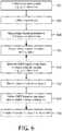
FIG. 6 , a method for generating a CMPR is illustratively shown in accordance with one embodiment. Inblock 602, shape sensing data (path information) is collected from a shape sensing device disposed within a three-dimensional structure, e.g., a vascular structure, a mechanical structure, etc. The shape sensing device may include one of an endoscope, a catheter, a guide-wire, etc. - In
block 604, an image volume may be collected for the structure using one or more imaging modalities. This may be performed in advance of any procedure and may be performed at a different location and time. Inblock 606, image volume parameters may optionally be adjusted during an acquisition of the image volume to limit collecting of volume data to regions intersecting with the shape sensing device. - In
block 608, the three-dimensional structure having the shape sensing device therein is registered with the image volume (i.e., the shape sensing space is registered with the image volume). The shape sensing device may include an imaging modality integrated therein. In such a case, the image volume and the shape sensing space are already registered. The image volume may include preoperative images of a subject or patient. The image volume may include a three-dimensional image of the structure taken by one or more of computed tomography, magnetic resonance imaging, fluoroscopy, ultrasound etc. - In
block 610, a curved multi-planar reconstruction (CMPR) image is generated from the shape sensing data such that the shape sensing data provides a path along which image volume data is employed to provide an image or images of the three-dimensional structure. This may include a warped linear or unrolled two dimensional view of the structure. The view is influenced and/or based upon the path acquired by the shape sensing device for the structure. The shape sensing data may include information over time for three-dimensional space and a rotation about an axis of the shape sensing device. The view of the structure may include locations where slices or cross-sections may be taken and concurrently viewed. Inblock 612, the cross-sections of the structure may be rendered along the path. - In
block 614, the CMPR may be refined each time a new shape is acquired for the shape sensing device or to gather additional information. Inblock 616, image data may be rescaled (e.g, may be part of the refinement) to account for movements in the structure. The movement may be due to heartbeats or other sources. The rescaling may include taking an average displacement or employing more sophisticated estimation tools to estimate appropriate dimensions in a CMPR view. - In interpreting the appended claims, it should be understood that:
- a) the word "comprising" does not exclude the presence of other elements or acts than those listed in a given claim;
- b) the word "a" or "an" preceding an element does not exclude the presence of a plurality of such elements;
- c) any reference signs in the claims do not limit their scope;
- d) several "means" may be represented by the same item or hardware or software implemented structure or function; and
- e) no specific sequence of acts is intended to be required unless specifically indicated.
- Having described preferred embodiments for curved multi-planar reconstruction using fiber optic shape data (which are intended to be illustrative and not limiting), it is noted that modifications and variations can be made by persons skilled in the art in light of the above teachings. It is therefore to be understood that changes may be made in the particular embodiments of the disclosure disclosed which are within the scope of the embodiments disclosed herein as outlined by the appended claims. Having thus described the details and particularity required by the patent laws, what is claimed and desired protected by Letters Patent is set forth in the appended claims.
Claims (15)
- A system, comprising:a shape sensing enabled device (102) having at least one optical fiber (126);an interpretation module (115) configured to receive optical signals from the at least one optical fiber within a structure and interpret the optical signals to determine a shape of the device; andan image generation module (140) configured to receive the shape of the device, register the shape with an image volume (130) of the structure and generate a curved multi-planar reconstruction (CMPR) rendering (402) based on the shape.
- The system as recited in claim 1, wherein the image volume (130) includes a three-dimensional image of the structure taken by one or more of computed tomography, magnetic resonance imaging, fluoroscopy, nuclear imaging and ultrasound.
- The system as recited in claim 1, wherein the shape sensing enabled device (102) includes an elongated instrument including one or more of an endoscope, a catheter and a guide-wire.
- The system as recited in claim 1, wherein the shape sensing enabled device (102) includes an imaging device configured to collect images at the shape sensing enabled medical device.
- The system as recited in claim 1, wherein the shape sensing enabled device (102) collects path information for the structure in three-dimensional space, about an axis of the at least one optical fiber and over time.
- The system as recited in claim 1, wherein the structure includes a vascular or endoluminal structure (204).
- The system as recited in claim 6, wherein the image generation module (140) rescales image data to account for movement in the vascular or endoluminal structure.
- The system as recited in claim 1, wherein the image generation module (140) rescales image data to account for movements in the structure.
- The system as recited in claim 1, wherein the shape sensing enabled device (102) collects path information to register and fuse non-Cartesian images with Cartesian images based upon the path information.
- A workstation comprising:a system to generate a curved multi-planar reconstruction (CMPR) based on the shape of a shape sensing enabled medical device as recited in claim landa display (118) for viewing the CMPR.
- The workstation as recited in claim 10, wherein the image volume (130) includes a three-dimensional image of the structure taken by one or more of computed tomography, magnetic resonance imaging, fluoroscopy, nuclear imaging and ultrasound.
- The workstation as recited in claim 10, wherein the shape sensing enabled device (102) includes an elongated instrument including one or more of an endoscope, a catheter and a guide-wire.
- The workstation as recited in claim 10, wherein the shape sensing enabled medical device (102) includes an imaging device configured to collect images at the shape sensing enabled medical device.
- The workstation as recited in claim 10, wherein the shape is used as path information and wherein the path information for the structure includes three-dimensional space, rotation about an axis of the at least one optical fiber and time.
- A method, comprising:collecting (602) shape sensing data from a shape sensing device disposed within a three-dimensional structure;registering (608) the three-dimensional structure having the shape sensing device therein with an image volume; andgenerating (610) a curved multi-planar reconstruction (CMPR) image from the shape sensing data such that the shape sensing data provides a path along which image volume data is employed to provide an image of the three-dimensional structure.
Applications Claiming Priority (2)
| Application Number | Priority Date | Filing Date | Title |
|---|---|---|---|
| US201161523930P | 2011-08-16 | 2011-08-16 | |
| PCT/IB2012/054108WO2013024418A1 (en) | 2011-08-16 | 2012-08-13 | Curved multi-planar reconstruction using fiber optic shape data |
Publications (2)
| Publication Number | Publication Date |
|---|---|
| EP2744407A1 EP2744407A1 (en) | 2014-06-25 |
| EP2744407B1true EP2744407B1 (en) | 2019-01-09 |
Family
ID=47137974
Family Applications (1)
| Application Number | Title | Priority Date | Filing Date |
|---|---|---|---|
| EP12781149.5AActiveEP2744407B1 (en) | 2011-08-16 | 2012-08-13 | Curved multi-planar reconstruction using fiber optic shape data |
Country Status (7)
| Country | Link |
|---|---|
| US (1) | US10575757B2 (en) |
| EP (1) | EP2744407B1 (en) |
| JP (1) | JP6114748B2 (en) |
| CN (1) | CN103781418B (en) |
| BR (1) | BR112014003281A2 (en) |
| RU (1) | RU2014110007A (en) |
| WO (1) | WO2013024418A1 (en) |
Families Citing this family (32)
| Publication number | Priority date | Publication date | Assignee | Title |
|---|---|---|---|---|
| CN102081697B (en)* | 2009-11-27 | 2013-12-11 | 深圳迈瑞生物医疗电子股份有限公司 | Method and device for defining interested volume in ultrasonic imaging space |
| EP2869754A2 (en) | 2012-07-09 | 2015-05-13 | Koninklijke Philips N.V. | Method and system for adaptive image guided intervention |
| EP2903552B1 (en) | 2012-10-01 | 2017-07-05 | Koninklijke Philips N.V. | Three dimensional polyline registration using shape constraints |
| WO2014167511A1 (en)* | 2013-04-12 | 2014-10-16 | Koninklijke Philips N.V. | Shape sensed ultrasound probe for fractional flow reserve simulation |
| EP3025304B1 (en)* | 2013-07-23 | 2021-09-08 | Koninklijke Philips N.V. | Registration system for registering an imaging device with a tracking device |
| WO2015071343A1 (en)* | 2013-11-13 | 2015-05-21 | Koninklijke Philips N.V. | Detection of rotational angle of an interventional device |
| WO2015110928A1 (en)* | 2014-01-24 | 2015-07-30 | Koninklijke Philips N.V. | Virtual image with optical shape sensing device perspective |
| US10772684B2 (en)* | 2014-02-11 | 2020-09-15 | Koninklijke Philips N.V. | Spatial visualization of internal mammary artery during minimally invasive bypass surgery |
| JP6713987B2 (en)* | 2014-09-08 | 2020-06-24 | コーニンクレッカ フィリップス エヌ ヴェKoninklijke Philips N.V. | Shape detection for orthopedic navigation |
| JP2017532146A (en)* | 2014-10-30 | 2017-11-02 | コーニンクレッカ フィリップス エヌ ヴェKoninklijke Philips N.V. | Ultrasonic visualization of curved structures |
| US9767620B2 (en) | 2014-11-26 | 2017-09-19 | Restoration Robotics, Inc. | Gesture-based editing of 3D models for hair transplantation applications |
| US10639007B2 (en) | 2014-12-02 | 2020-05-05 | Koninklijke Philips N.V. | Automatic tracking and registration of ultrasound probe using optical shape sensing without tip fixation |
| EP3037056B1 (en) | 2014-12-23 | 2021-04-21 | Stryker European Holdings I, LLC | System for reconstructing a trajectory of an optical fiber |
| JP2018511353A (en)* | 2015-01-22 | 2018-04-26 | コーニンクレッカ フィリップス エヌ ヴェKoninklijke Philips N.V. | Device visualization by optical shape sensing of guide wires |
| US20160225180A1 (en)* | 2015-01-29 | 2016-08-04 | Siemens Medical Solutions Usa, Inc. | Measurement tools with plane projection in rendered ultrasound volume imaging |
| CN107660134B (en)* | 2015-05-22 | 2021-06-29 | 直观外科手术操作公司 | System and method for image-guided surgical recording |
| CN108024783A (en)* | 2015-09-16 | 2018-05-11 | 皇家飞利浦有限公司 | Device for vascular characterization |
| EP3349659A1 (en)* | 2015-09-16 | 2018-07-25 | Koninklijke Philips N.V. | Apparatus for vessel characterization |
| CN108135530B (en)* | 2015-10-02 | 2023-01-17 | 皇家飞利浦有限公司 | A hub for device navigation utilizing optical shape-sensing guidewires |
| US10132891B2 (en)* | 2016-09-16 | 2018-11-20 | General Electric Company | System and method for attenuation correction of a surface coil in a PET-MRI system |
| EP3420914A1 (en) | 2017-06-30 | 2019-01-02 | Koninklijke Philips N.V. | Ultrasound system and method |
| CN111329587A (en)* | 2020-02-19 | 2020-06-26 | 上海理工大学 | Surgical registration system using shape sensing fiber optic mesh |
| WO2021175629A1 (en) | 2020-03-05 | 2021-09-10 | Koninklijke Philips N.V. | Contextual multiplanar reconstruction of three-dimensional ultrasound imaging data and associated devices, systems, and methods |
| US11877810B2 (en) | 2020-07-21 | 2024-01-23 | Bard Access Systems, Inc. | System, method and apparatus for magnetic tracking of ultrasound probe and generation of 3D visualization thereof |
| EP3944809A1 (en) | 2020-07-28 | 2022-02-02 | Koninklijke Philips N.V. | Arrangement and method for determining the position of an invasive device |
| EP4185209A1 (en) | 2020-08-04 | 2023-05-31 | Bard Access Systems, Inc. | System and method for optimized medical component insertion monitoring and imaging enhancement |
| WO2022035760A1 (en) | 2020-08-10 | 2022-02-17 | Bard Access Systems, Inc. | System and method for generating vessel representations in mixed reality/virtual reality |
| WO2022072727A2 (en) | 2020-10-02 | 2022-04-07 | Bard Access Systems, Inc. | Ultrasound systems and methods for sustained spatial attention |
| EP4228516A1 (en) | 2020-10-15 | 2023-08-23 | Bard Access Systems, Inc. | Ultrasound imaging system for generation of a three-dimensional ultrasound image |
| EP4282366A1 (en)* | 2022-05-23 | 2023-11-29 | Koninklijke Philips N.V. | Shape registration of a shape-sensing enabled device to an imaging system |
| US12102481B2 (en)* | 2022-06-03 | 2024-10-01 | Bard Access Systems, Inc. | Ultrasound probe with smart accessory |
| US12137989B2 (en) | 2022-07-08 | 2024-11-12 | Bard Access Systems, Inc. | Systems and methods for intelligent ultrasound probe guidance |
Family Cites Families (13)
| Publication number | Priority date | Publication date | Assignee | Title |
|---|---|---|---|---|
| CA2325036A1 (en)* | 1999-10-29 | 2001-04-29 | Advanced Sensor Technology, Llc | Optical fiber navigation system |
| JP2002306403A (en)* | 2001-04-18 | 2002-10-22 | Olympus Optical Co Ltd | Endoscope |
| JP4421203B2 (en)* | 2003-03-20 | 2010-02-24 | 株式会社東芝 | Luminous structure analysis processing device |
| JP2007044121A (en)* | 2005-08-08 | 2007-02-22 | Hitachi Medical Corp | Medical image display method and apparatus |
| CN1911155A (en)* | 2005-08-11 | 2007-02-14 | 奥林巴斯医疗株式会社 | Endoscopic procedure education system |
| JP5022667B2 (en)* | 2005-10-21 | 2012-09-12 | 株式会社東芝 | Medical image processing apparatus and medical image processing method |
| US8248413B2 (en)* | 2006-09-18 | 2012-08-21 | Stryker Corporation | Visual navigation system for endoscopic surgery |
| DE102006046045B4 (en) | 2006-09-28 | 2014-05-28 | Siemens Aktiengesellschaft | Method for two-dimensional or three-dimensional imaging of a target area of interest in a hollow organ and medical examination and treatment system |
| JP5085142B2 (en)* | 2007-01-22 | 2012-11-28 | オリンパス株式会社 | Endoscope system and method for operating apparatus for detecting shape of endoscope insertion portion used therefor |
| EP2188782B1 (en)* | 2007-08-03 | 2018-11-07 | Koninklijke Philips N.V. | Coupling the viewing direction of a blood vessel's cpr view with the viewing angle on this 3d tubular structure's rendered voxel volume and/or with the c-arm geometry of a 3d rotational angiography device's c-arm system |
| JP2009160205A (en) | 2008-01-04 | 2009-07-23 | Toshiba Corp | Medical support apparatus, medical support program, and radiographic apparatus |
| JP5641736B2 (en)* | 2008-03-25 | 2014-12-17 | 株式会社東芝 | Medical image processing apparatus and X-ray diagnostic apparatus |
| JP6574378B2 (en)* | 2012-08-04 | 2019-09-11 | コーニンクレッカ フィリップス エヌ ヴェKoninklijke Philips N.V. | Quantifying probe deflection to improve catheter identification |
- 2012
- 2012-08-13JPJP2014525539Apatent/JP6114748B2/enactiveActive
- 2012-08-13BRBR112014003281Apatent/BR112014003281A2/ennot_activeIP Right Cessation
- 2012-08-13USUS14/236,331patent/US10575757B2/enactiveActive
- 2012-08-13WOPCT/IB2012/054108patent/WO2013024418A1/enactiveApplication Filing
- 2012-08-13CNCN201280039729.9Apatent/CN103781418B/enactiveActive
- 2012-08-13EPEP12781149.5Apatent/EP2744407B1/enactiveActive
- 2012-08-13RURU2014110007/14Apatent/RU2014110007A/ennot_activeApplication Discontinuation
Non-Patent Citations (1)
| Title |
|---|
| None* |
Also Published As
| Publication number | Publication date |
|---|---|
| US20140155737A1 (en) | 2014-06-05 |
| RU2014110007A (en) | 2015-09-27 |
| JP6114748B2 (en) | 2017-04-12 |
| JP2014526927A (en) | 2014-10-09 |
| CN103781418B (en) | 2016-03-02 |
| CN103781418A (en) | 2014-05-07 |
| US10575757B2 (en) | 2020-03-03 |
| EP2744407A1 (en) | 2014-06-25 |
| WO2013024418A1 (en) | 2013-02-21 |
| BR112014003281A2 (en) | 2017-04-18 |
Similar Documents
| Publication | Publication Date | Title |
|---|---|---|
| EP2744407B1 (en) | Curved multi-planar reconstruction using fiber optic shape data | |
| JP7050733B6 (en) | Virtual image with viewpoint of optical shape detector | |
| EP2830502B1 (en) | Artifact removal using shape sensing | |
| US11547489B2 (en) | Shape sensing of multiple over-the-wire devices | |
| EP2677937B1 (en) | Non-rigid-body morphing of vessel image using intravascular device shape | |
| US10729340B2 (en) | Shape sensed ultrasound probe for fractional flow reserve simulation | |
| EP2866642B1 (en) | Fiber optic sensor guided navigation for vascular visualization and monitoring | |
| CN104349715B (en) | Distributed sensing device for reference to physiological characteristics | |
| US11406278B2 (en) | Non-rigid-body morphing of vessel image using intravascular device shape | |
| JP2017537698A5 (en) | ||
| EP3082610A1 (en) | Shape sensed robotic ultrasound for minimally invasive interventions |
Legal Events
| Date | Code | Title | Description |
|---|---|---|---|
| PUAI | Public reference made under article 153(3) epc to a published international application that has entered the european phase | Free format text:ORIGINAL CODE: 0009012 | |
| 17P | Request for examination filed | Effective date:20140317 | |
| AK | Designated contracting states | Kind code of ref document:A1 Designated state(s):AL AT BE BG CH CY CZ DE DK EE ES FI FR GB GR HR HU IE IS IT LI LT LU LV MC MK MT NL NO PL PT RO RS SE SI SK SM TR | |
| DAX | Request for extension of the european patent (deleted) | ||
| GRAP | Despatch of communication of intention to grant a patent | Free format text:ORIGINAL CODE: EPIDOSNIGR1 | |
| STAA | Information on the status of an ep patent application or granted ep patent | Free format text:STATUS: GRANT OF PATENT IS INTENDED | |
| INTG | Intention to grant announced | Effective date:20180801 | |
| GRAS | Grant fee paid | Free format text:ORIGINAL CODE: EPIDOSNIGR3 | |
| GRAA | (expected) grant | Free format text:ORIGINAL CODE: 0009210 | |
| STAA | Information on the status of an ep patent application or granted ep patent | Free format text:STATUS: THE PATENT HAS BEEN GRANTED | |
| AK | Designated contracting states | Kind code of ref document:B1 Designated state(s):AL AT BE BG CH CY CZ DE DK EE ES FI FR GB GR HR HU IE IS IT LI LT LU LV MC MK MT NL NO PL PT RO RS SE SI SK SM TR | |
| REG | Reference to a national code | Ref country code:GB Ref legal event code:FG4D | |
| REG | Reference to a national code | Ref country code:CH Ref legal event code:EP Ref country code:AT Ref legal event code:REF Ref document number:1086315 Country of ref document:AT Kind code of ref document:T Effective date:20190115 | |
| REG | Reference to a national code | Ref country code:DE Ref legal event code:R096 Ref document number:602012055749 Country of ref document:DE | |
| REG | Reference to a national code | Ref country code:IE Ref legal event code:FG4D | |
| REG | Reference to a national code | Ref country code:NL Ref legal event code:MP Effective date:20190109 | |
| REG | Reference to a national code | Ref country code:LT Ref legal event code:MG4D | |
| PG25 | Lapsed in a contracting state [announced via postgrant information from national office to epo] | Ref country code:NL Free format text:LAPSE BECAUSE OF FAILURE TO SUBMIT A TRANSLATION OF THE DESCRIPTION OR TO PAY THE FEE WITHIN THE PRESCRIBED TIME-LIMIT Effective date:20190109 | |
| REG | Reference to a national code | Ref country code:AT Ref legal event code:MK05 Ref document number:1086315 Country of ref document:AT Kind code of ref document:T Effective date:20190109 | |
| PG25 | Lapsed in a contracting state [announced via postgrant information from national office to epo] | Ref country code:ES Free format text:LAPSE BECAUSE OF FAILURE TO SUBMIT A TRANSLATION OF THE DESCRIPTION OR TO PAY THE FEE WITHIN THE PRESCRIBED TIME-LIMIT Effective date:20190109 Ref country code:SE Free format text:LAPSE BECAUSE OF FAILURE TO SUBMIT A TRANSLATION OF THE DESCRIPTION OR TO PAY THE FEE WITHIN THE PRESCRIBED TIME-LIMIT Effective date:20190109 Ref country code:PT Free format text:LAPSE BECAUSE OF FAILURE TO SUBMIT A TRANSLATION OF THE DESCRIPTION OR TO PAY THE FEE WITHIN THE PRESCRIBED TIME-LIMIT Effective date:20190509 Ref country code:FI Free format text:LAPSE BECAUSE OF FAILURE TO SUBMIT A TRANSLATION OF THE DESCRIPTION OR TO PAY THE FEE WITHIN THE PRESCRIBED TIME-LIMIT Effective date:20190109 Ref country code:NO Free format text:LAPSE BECAUSE OF FAILURE TO SUBMIT A TRANSLATION OF THE DESCRIPTION OR TO PAY THE FEE WITHIN THE PRESCRIBED TIME-LIMIT Effective date:20190409 Ref country code:PL Free format text:LAPSE BECAUSE OF FAILURE TO SUBMIT A TRANSLATION OF THE DESCRIPTION OR TO PAY THE FEE WITHIN THE PRESCRIBED TIME-LIMIT Effective date:20190109 Ref country code:LT Free format text:LAPSE BECAUSE OF FAILURE TO SUBMIT A TRANSLATION OF THE DESCRIPTION OR TO PAY THE FEE WITHIN THE PRESCRIBED TIME-LIMIT Effective date:20190109 | |
| PG25 | Lapsed in a contracting state [announced via postgrant information from national office to epo] | Ref country code:BG Free format text:LAPSE BECAUSE OF FAILURE TO SUBMIT A TRANSLATION OF THE DESCRIPTION OR TO PAY THE FEE WITHIN THE PRESCRIBED TIME-LIMIT Effective date:20190409 Ref country code:IS Free format text:LAPSE BECAUSE OF FAILURE TO SUBMIT A TRANSLATION OF THE DESCRIPTION OR TO PAY THE FEE WITHIN THE PRESCRIBED TIME-LIMIT Effective date:20190509 Ref country code:HR Free format text:LAPSE BECAUSE OF FAILURE TO SUBMIT A TRANSLATION OF THE DESCRIPTION OR TO PAY THE FEE WITHIN THE PRESCRIBED TIME-LIMIT Effective date:20190109 Ref country code:LV Free format text:LAPSE BECAUSE OF FAILURE TO SUBMIT A TRANSLATION OF THE DESCRIPTION OR TO PAY THE FEE WITHIN THE PRESCRIBED TIME-LIMIT Effective date:20190109 Ref country code:RS Free format text:LAPSE BECAUSE OF FAILURE TO SUBMIT A TRANSLATION OF THE DESCRIPTION OR TO PAY THE FEE WITHIN THE PRESCRIBED TIME-LIMIT Effective date:20190109 Ref country code:GR Free format text:LAPSE BECAUSE OF FAILURE TO SUBMIT A TRANSLATION OF THE DESCRIPTION OR TO PAY THE FEE WITHIN THE PRESCRIBED TIME-LIMIT Effective date:20190410 | |
| REG | Reference to a national code | Ref country code:DE Ref legal event code:R097 Ref document number:602012055749 Country of ref document:DE | |
| PG25 | Lapsed in a contracting state [announced via postgrant information from national office to epo] | Ref country code:RO Free format text:LAPSE BECAUSE OF FAILURE TO SUBMIT A TRANSLATION OF THE DESCRIPTION OR TO PAY THE FEE WITHIN THE PRESCRIBED TIME-LIMIT Effective date:20190109 Ref country code:IT Free format text:LAPSE BECAUSE OF FAILURE TO SUBMIT A TRANSLATION OF THE DESCRIPTION OR TO PAY THE FEE WITHIN THE PRESCRIBED TIME-LIMIT Effective date:20190109 Ref country code:EE Free format text:LAPSE BECAUSE OF FAILURE TO SUBMIT A TRANSLATION OF THE DESCRIPTION OR TO PAY THE FEE WITHIN THE PRESCRIBED TIME-LIMIT Effective date:20190109 Ref country code:CZ Free format text:LAPSE BECAUSE OF FAILURE TO SUBMIT A TRANSLATION OF THE DESCRIPTION OR TO PAY THE FEE WITHIN THE PRESCRIBED TIME-LIMIT Effective date:20190109 Ref country code:AT Free format text:LAPSE BECAUSE OF FAILURE TO SUBMIT A TRANSLATION OF THE DESCRIPTION OR TO PAY THE FEE WITHIN THE PRESCRIBED TIME-LIMIT Effective date:20190109 Ref country code:DK Free format text:LAPSE BECAUSE OF FAILURE TO SUBMIT A TRANSLATION OF THE DESCRIPTION OR TO PAY THE FEE WITHIN THE PRESCRIBED TIME-LIMIT Effective date:20190109 Ref country code:SK Free format text:LAPSE BECAUSE OF FAILURE TO SUBMIT A TRANSLATION OF THE DESCRIPTION OR TO PAY THE FEE WITHIN THE PRESCRIBED TIME-LIMIT Effective date:20190109 Ref country code:AL Free format text:LAPSE BECAUSE OF FAILURE TO SUBMIT A TRANSLATION OF THE DESCRIPTION OR TO PAY THE FEE WITHIN THE PRESCRIBED TIME-LIMIT Effective date:20190109 | |
| PLBE | No opposition filed within time limit | Free format text:ORIGINAL CODE: 0009261 | |
| STAA | Information on the status of an ep patent application or granted ep patent | Free format text:STATUS: NO OPPOSITION FILED WITHIN TIME LIMIT | |
| PG25 | Lapsed in a contracting state [announced via postgrant information from national office to epo] | Ref country code:SM Free format text:LAPSE BECAUSE OF FAILURE TO SUBMIT A TRANSLATION OF THE DESCRIPTION OR TO PAY THE FEE WITHIN THE PRESCRIBED TIME-LIMIT Effective date:20190109 | |
| 26N | No opposition filed | Effective date:20191010 | |
| PG25 | Lapsed in a contracting state [announced via postgrant information from national office to epo] | Ref country code:SI Free format text:LAPSE BECAUSE OF FAILURE TO SUBMIT A TRANSLATION OF THE DESCRIPTION OR TO PAY THE FEE WITHIN THE PRESCRIBED TIME-LIMIT Effective date:20190109 | |
| PG25 | Lapsed in a contracting state [announced via postgrant information from national office to epo] | Ref country code:TR Free format text:LAPSE BECAUSE OF FAILURE TO SUBMIT A TRANSLATION OF THE DESCRIPTION OR TO PAY THE FEE WITHIN THE PRESCRIBED TIME-LIMIT Effective date:20190109 | |
| PG25 | Lapsed in a contracting state [announced via postgrant information from national office to epo] | Ref country code:LU Free format text:LAPSE BECAUSE OF NON-PAYMENT OF DUE FEES Effective date:20190813 Ref country code:MC Free format text:LAPSE BECAUSE OF FAILURE TO SUBMIT A TRANSLATION OF THE DESCRIPTION OR TO PAY THE FEE WITHIN THE PRESCRIBED TIME-LIMIT Effective date:20190109 Ref country code:CH Free format text:LAPSE BECAUSE OF NON-PAYMENT OF DUE FEES Effective date:20190831 Ref country code:LI Free format text:LAPSE BECAUSE OF NON-PAYMENT OF DUE FEES Effective date:20190831 | |
| REG | Reference to a national code | Ref country code:BE Ref legal event code:MM Effective date:20190831 | |
| PG25 | Lapsed in a contracting state [announced via postgrant information from national office to epo] | Ref country code:IE Free format text:LAPSE BECAUSE OF NON-PAYMENT OF DUE FEES Effective date:20190813 | |
| PG25 | Lapsed in a contracting state [announced via postgrant information from national office to epo] | Ref country code:BE Free format text:LAPSE BECAUSE OF NON-PAYMENT OF DUE FEES Effective date:20190831 | |
| PG25 | Lapsed in a contracting state [announced via postgrant information from national office to epo] | Ref country code:CY Free format text:LAPSE BECAUSE OF FAILURE TO SUBMIT A TRANSLATION OF THE DESCRIPTION OR TO PAY THE FEE WITHIN THE PRESCRIBED TIME-LIMIT Effective date:20190109 | |
| PG25 | Lapsed in a contracting state [announced via postgrant information from national office to epo] | Ref country code:HU Free format text:LAPSE BECAUSE OF FAILURE TO SUBMIT A TRANSLATION OF THE DESCRIPTION OR TO PAY THE FEE WITHIN THE PRESCRIBED TIME-LIMIT; INVALID AB INITIO Effective date:20120813 Ref country code:MT Free format text:LAPSE BECAUSE OF FAILURE TO SUBMIT A TRANSLATION OF THE DESCRIPTION OR TO PAY THE FEE WITHIN THE PRESCRIBED TIME-LIMIT Effective date:20190109 | |
| PG25 | Lapsed in a contracting state [announced via postgrant information from national office to epo] | Ref country code:MK Free format text:LAPSE BECAUSE OF FAILURE TO SUBMIT A TRANSLATION OF THE DESCRIPTION OR TO PAY THE FEE WITHIN THE PRESCRIBED TIME-LIMIT Effective date:20190109 | |
| PGFP | Annual fee paid to national office [announced via postgrant information from national office to epo] | Ref country code:DE Payment date:20240828 Year of fee payment:13 | |
| PGFP | Annual fee paid to national office [announced via postgrant information from national office to epo] | Ref country code:GB Payment date:20240827 Year of fee payment:13 | |
| PGFP | Annual fee paid to national office [announced via postgrant information from national office to epo] | Ref country code:FR Payment date:20240826 Year of fee payment:13 |