EP2742542B1 - Systems and methods of antenna orientation in a point-to-point wireless network - Google Patents
Systems and methods of antenna orientation in a point-to-point wireless networkDownload PDFInfo
- Publication number
- EP2742542B1 EP2742542B1EP12821784.1AEP12821784AEP2742542B1EP 2742542 B1EP2742542 B1EP 2742542B1EP 12821784 AEP12821784 AEP 12821784AEP 2742542 B1EP2742542 B1EP 2742542B1
- Authority
- EP
- European Patent Office
- Prior art keywords
- antenna
- signal
- gain
- relative
- gains
- Prior art date
- Legal status (The legal status is an assumption and is not a legal conclusion. Google has not performed a legal analysis and makes no representation as to the accuracy of the status listed.)
- Active
Links
Images


Classifications
- H—ELECTRICITY
- H04—ELECTRIC COMMUNICATION TECHNIQUE
- H04W—WIRELESS COMMUNICATION NETWORKS
- H04W16/00—Network planning, e.g. coverage or traffic planning tools; Network deployment, e.g. resource partitioning or cells structures
- H04W16/24—Cell structures
- H04W16/28—Cell structures using beam steering
- H—ELECTRICITY
- H01—ELECTRIC ELEMENTS
- H01Q—ANTENNAS, i.e. RADIO AERIALS
- H01Q17/00—Devices for absorbing waves radiated from an antenna; Combinations of such devices with active antenna elements or systems
- H01Q17/001—Devices for absorbing waves radiated from an antenna; Combinations of such devices with active antenna elements or systems for modifying the directional characteristic of an aerial
- G—PHYSICS
- G01—MEASURING; TESTING
- G01R—MEASURING ELECTRIC VARIABLES; MEASURING MAGNETIC VARIABLES
- G01R29/00—Arrangements for measuring or indicating electric quantities not covered by groups G01R19/00 - G01R27/00
- G01R29/08—Measuring electromagnetic field characteristics
- G01R29/10—Radiation diagrams of antennas
- H—ELECTRICITY
- H01—ELECTRIC ELEMENTS
- H01Q—ANTENNAS, i.e. RADIO AERIALS
- H01Q1/00—Details of, or arrangements associated with, antennas
- H01Q1/12—Supports; Mounting means
- H01Q1/125—Means for positioning
- H01Q1/1257—Means for positioning using the received signal strength
- H—ELECTRICITY
- H04—ELECTRIC COMMUNICATION TECHNIQUE
- H04B—TRANSMISSION
- H04B17/00—Monitoring; Testing
- H04B17/10—Monitoring; Testing of transmitters
- H04B17/11—Monitoring; Testing of transmitters for calibration
- H04B17/12—Monitoring; Testing of transmitters for calibration of transmit antennas, e.g. of the amplitude or phase
- H—ELECTRICITY
- H04—ELECTRIC COMMUNICATION TECHNIQUE
- H04B—TRANSMISSION
- H04B17/00—Monitoring; Testing
- H04B17/20—Monitoring; Testing of receivers
- H04B17/23—Indication means, e.g. displays, alarms, audible means
- H—ELECTRICITY
- H04—ELECTRIC COMMUNICATION TECHNIQUE
- H04B—TRANSMISSION
- H04B17/00—Monitoring; Testing
- H04B17/30—Monitoring; Testing of propagation channels
- H04B17/309—Measuring or estimating channel quality parameters
- H—ELECTRICITY
- H04—ELECTRIC COMMUNICATION TECHNIQUE
- H04B—TRANSMISSION
- H04B7/00—Radio transmission systems, i.e. using radiation field
- H04B7/02—Diversity systems; Multi-antenna system, i.e. transmission or reception using multiple antennas
- H04B7/04—Diversity systems; Multi-antenna system, i.e. transmission or reception using multiple antennas using two or more spaced independent antennas
- H04B7/08—Diversity systems; Multi-antenna system, i.e. transmission or reception using multiple antennas using two or more spaced independent antennas at the receiving station
- H04B7/0882—Diversity systems; Multi-antenna system, i.e. transmission or reception using multiple antennas using two or more spaced independent antennas at the receiving station using post-detection diversity
- H—ELECTRICITY
- H01—ELECTRIC ELEMENTS
- H01Q—ANTENNAS, i.e. RADIO AERIALS
- H01Q25/00—Antennas or antenna systems providing at least two radiating patterns
- H01Q25/002—Antennas or antenna systems providing at least two radiating patterns providing at least two patterns of different beamwidth; Variable beamwidth antennas
Definitions
- the present invention(s)relate to wireless network systems, and more particularly, to systems and methods of antenna orientation in a point-to-point wireless network.
- Wireless antenna systemssuch as microwave antenna system
- Large amounts of informationmay be transmitted at high frequencies between antennas.
- Point-to-point antenna systemsare often used to increase, increase other desirable signal characteristics, and/or allow greater distances between antennas.
- e-band wireless systemsmay offer full-duplex gigabit Ethernet connectivity at data rates of 1 Gbps and higher.
- the e-bandincludes 71-76 and 81-86 GHz bands. Since gain of an antenna increases with frequency, it is possible to realize large gains from small antennas at e-band frequencies. For example, at the e-band of a 30 cm parabolic antenna has a gain of 44 to 45 dBi. An extra 24 dB allows for a significant distance increases between antennas.
- a monocularmay be coupled to an antenna to assist in antenna alignment and/or orientation.
- mirrors and lasershave been used to assist in alignment.
- pollution or other obstructions that limit visibilitymay limit the effectiveness of optical alignment.
- the installerneeds to know exact location of the remote site which can be very challenging in an urban environment.
- Prior publication EP1659813 A1refers to a communication system and method in which first and second stations are adapted to automatically establish at least one alternative communication part for wireless communication via narrow beam antennas.
- US Statutory Invention Registration H1034refers to a millimetre wave Cassegrain antenna for a seeker missile.
- US 3,364,490teaches a variable beam width antenna utilising defocusing relating to variable beam width double-reflector mono pulse antennas.
- US 7,663,560refer to a satellite system having an outdoor unit that has a low noise black (LNB) and having an antenna that relies on using a microwave energy absorbing cap.
- LNBlow noise black
- An exemplary methodcomprises positioning a first antenna to receive a first signal from a second antenna, the second antenna comprising energy absorbing material that functions to expand beamwidth, receiving the first signal from the second antenna, detecting a plurality of gains based on the first signal, repositioning the first antenna relative to the second antenna to a position associated with an acceptable gain based on the first signal, removing at least some of the energy absorbing material from the second antenna to narrow the beamwidth of the second antenna, receiving, by the first antenna, a second signal from the second antenna, detecting a plurality of gains based on the second signal, and repositioning the first antenna relative to the second antenna to a position associated with an increased gain of the plurality of gains based on the second signal, the increased gain being greater than the acceptable gain.
- the methodmay further comprise measuring a voltage associated with the first signal to detect the plurality of gains associated with different positions of the first antenna relative to the second antenna.
- the energy absorbing materialnarrows an aperture of the second antenna to broaden the beamwidth of the second antenna.
- the energy absorbing materialmay be adhered to the second antenna and removed from the second antenna by peeling the at least some of the energy absorbing material from the second antenna.
- repositioning the first antenna relative to the second antenna to the position associated with the increased gain of the plurality of gains based on the second signal, the increased gain being greater than the acceptable gain of the plurality of gains based on the first signalmay comprise repositioning the first antenna relative to the second antenna based on the maximum gain of the plurality of gains based on the second signal.
- Detecting the plurality of gains based on the second signal, each gain associated with the different position of the first antenna relative to the second antennamay comprise detecting the plurality of gains associated with different positions of the first antenna relative to the second antenna until detection of the increased gain, the increased gain being above a second predetermined threshold.
- the methodmay further comprise receiving, by the second antenna, a third signal from the first antenna, detecting a plurality of gains associated with different positions of the second antenna relative to the first antenna, and repositioning the second antenna relative to the first antenna to adjust a detected gain of the third signal.
- the methodmay also comprise removing at least some of energy absorbing material from the first antenna to narrow a beamwidth of the first antenna, receiving, by the second antenna, a fourth signal from the first antenna, detecting a plurality of gains based on the fourth signal, each gain associated with a different position of the second antenna relative to the first antenna, and repositioning the second antenna relative to the first antenna to a position associated with an increased gain of the plurality of gains based on the fourth signal, the increased gain being greater than the acceptable gain of the plurality of gains based on the third signal.
- An exemplary systemcomprises a first antenna and a meter.
- the first antennamay be configured to be positioned to receive a first signal from a second antenna, the first antenna comprising energy absorbing material, the energy absorbing material enabling expansion of a beamwidth of the first antenna, the first antenna configured to be repositioned relative to the second antenna based on an acceptable gain of the first signal, to be positioned to receive a second signal from the second antenna, at least some of the energy absorbing material being removed from the first antenna prior to reception of the second signal, the first antenna configured to be repositioned relative to the second antenna based on an increased gain of the second signal, the increased gain being greater than the acceptable gain of the plurality of gains based on the first signal.
- the metercoupled to the first antenna and configured to determine if a detected gain of the first signal is greater than or equal to the acceptable gain and to determine if a detected gain of the second signal is greater than or equal to the increased gain.
- Another exemplary embodimentscomprises positioning a first antenna to receive a first signal from a second antenna, the first antenna comprising energy absorbing material that functions to expand beamwidth of the first antenna, receiving, by the first antenna, the first signal from the second antenna, detecting a plurality of gains based on the first signal, each gain associated with a different position of the first antenna relative to the second antenna, repositioning the first antenna relative to the second antenna to a position associated with an acceptable gain of the plurality of gains based on the first signal, removing at least some of the energy absorbing material from the first antenna to narrow the beamwidth of the first antenna, receiving, by the first antenna, a second signal from the second antenna, detecting a plurality of gains based on the second signal, each gain associated with a different position of the first antenna relative to the second antenna, and repositioning the first antenna relative to the second antenna to a position associated with an increased gain of the plurality of gains based on the second signal, the increased gain being greater than the acceptable gain of the plurality of gains based on
- An exemplary systemcomprises a first antenna and a meter.
- the first antennamay be configured to be positioned to receive a first signal from a second antenna, the second antenna comprising energy absorbing material, the energy absorbing material enabling expansion of a beamwidth of the second antenna, the first antenna configured to be repositioned relative to the second antenna based on an acceptable gain of the first signal, to be positioned to receive a second signal from the second antenna, at least some of the energy absorbing material being removed from the second antenna prior to reception of the second signal, the first antenna configured to be repositioned relative to the second antenna based on an increased gain of the second signal, the increased gain being greater than the acceptable gain of the plurality of gains based on the first signal.
- the metermay be coupled to the first antenna and configured to determine if a detected gain of the first signal is greater than or equal to the acceptable gain and to determine if a detected gain of the second signal is greater than or equal to the increased gain.
- FIG. 1depicts a local antenna 102 in communication with a remote antenna 104 in some embodiments.
- the local antenna 102 and remote antenna 104may be any type of antenna including, for example, a parabolic antenna (e.g., aperture antenna).
- a parabolic antennais an antenna that uses a parabolic reflector to direct radio waves.
- An exemplary parabolic antennamay comprise a reflector element and a feed antenna.
- the reflector elementmay be made of many different types of material and may be any shape (e.g., circular dish, rectangular, or the like).
- the feed antennais typically at the reflector's focus and is a low-gain type antenna.
- the local antenna 102 and the remote antenna 104may be any kind of antennas.
- Many antennasutilize point-to-point transmission systems to obtain necessary gain and/or other desired signal characteristics over significant distances.
- Directing a radiation pattern with a narrow beamwidth from a transmitting antenna (e.g., transmitting effectiveness) and/or a receiving antenna (e.g., receiving effectiveness) in a point-to-point wireless networkallows for increased gain or other improved signal characteristics.
- Obtaining greater gain and/or other improved signal characteristicsmay increase reliability in poor weather conditions and may also allow for the receive and transmission antennas to be spaced further apart.
- the distance between the two antennasincrease and the beamwidths of one or both radiation patterns of the antennas narrows, it becomes increasingly difficult to position each antenna such that each antenna detects a signal from the other.
- Even if a receiving antennais generally positioned relative to the transmitting antenna, it remains difficult to adjust the orientation and position of the receiving antenna to reliably improve or maximize gain or other signal characteristics.
- the two antennasare typically positioned to allow the pencil beam to be directed to the receiving antenna such that the receiving antenna may receive a signal from the transmitting antenna.
- Considerable timemay be wasted as the antennas are adjusted until the receiving antenna is within the radiation pattern of the transmitting antenna.
- workers at the receiving antenna and workers at the transmitting antennamove the antenna elements (e.g., the "dish") such that a signal from the transmitting antenna may be received by the receiving antenna. If a signal is detected, then the receiving antenna may be further oriented or repositioned to maximize gain or other signal characteristics of the signal (e.g., adjusting position of the receiving element of the receive antenna).
- the transmitting antennamay also be oriented to improve gain at the receiving antenna.
- millimeter wave point-to-point antennasmay have a 3 dB beamwidth of 1.2 degrees (e.g., gain of 43dBi for 30cm dish antenna at 80GHz - a typical type of antenna for E-band point-to-point applications). If the initial antenna orientation is within +1-6 degrees in azimuth and elevation of the correct direction, there may be 10 discrete orientation positions for each polarization (e.g., 100 direction spots in AZ-EL plane). In case the link fade margin is below antenna sidelobe levels (typical SLL are >30dB), the time to align the antennas can be very high.
- Much faster antenna orientationcan be achieved by temporary widening the antenna beamwidth (e.g., with beamwidth of 3.6 degrees).
- the antenna orientationmay be much faster while still feasible as the antenna gain may reduce less than the link fade margin (e.g., 2 x 9.5dB).
- Antenna alignmentmay involve adjusting the direction of each antenna until the received signal strength reaches a desired or maximum level at each end of the link. Fine adjustment for azimuth (horizontal angel) and elevation (vertical angel) may be built into each antenna mount. Adjustment procedures may be provided with each antenna.
- the antenna mounting bracketsmay need to be loosened and the antenna swiveled on its pole mount to locate the beam.
- Some mounts for larger antennasmay have a separately clamped swivel base to allow the loosened antenna to swivel on it without fear of slipping down the pole. Where such a mount is not provided a temporary swivel clamp may be provided using a pair of pipe brackets bolted together immediately below the antenna mount.
- FIG. 2is a diagram depicting a transmitting antenna 202 and a receiving antenna 204 in some embodiments.
- the transmitting radiation pattern 206 of the transmitting antenna 202may be broadened (e.g., the beamwidth of the transmitting radiation pattern broadened) such that the receiving antenna 204 may more easily be positioned to detect a signal from the transmitting antenna.
- the receiving antenna 304may be further oriented or repositioned such that the receiving antenna 304 may maximize or receive a desired gain and/or other characteristic of the signal.
- the transmitting antenna 202may also be repositioned such that the receiving antenna 204 receives a signal with maximum gain or other characteristic.
- the receiving antenna 204may be more easily positioned and repositioned to find a signal from the transmitting antenna 202 when the transmitting radiation pattern 206 is broader.
- a signalmay be more easily detected by generally directing the receiving antenna 204 towards the transmitting antenna 202.
- minor adjustments to the orientation and/or positionmay be made to find a maximum gain or a gain above a predetermined threshold (e.g., above an acceptable gain).
- a predetermined thresholde.g., above an acceptable gain.
- any signal characteristics, not just gainmay be used. For example, adjustments to the receiving antenna 204 may be performed to maximize desirable signal characteristics and/or minimize undesirable signal characteristics.
- the transmitting radiation pattern from the transmitting antenna 202may be narrowed (e.g., a pencil beam is directed from the transmitting antenna 202 to the receiving antenna 204). Since the receiving antenna 204 is already oriented towards the transmitting antenna 202, the receiving antenna 204 may more easily find subsequent signals from the transmitting antenna 202. Once the subsequent signals from the transmitting antenna 202 is detected, the receiving antenna 202 may, again, be adjusted to maximize gain or gain above a second predetermined threshold (e.g., above an increased gain, the increased gain being greater than the acceptable gain). As discussed herein, adjustments to the receiving antenna 204 may be performed to maximize desirable signal characteristics and/or minimize undesirable signal characteristics of the subsequent signals.
- a second predetermined thresholde.g., above an increased gain, the increased gain being greater than the acceptable gain
- the processmay be iterative. For example, the process may continue as the radiation beam associated with the transmitting antenna is repeatedly narrowed after the receiving antenna detects a signal from the transmission antenna and the position adjusted to achieve the desired or expected characteristics.
- the receiving antenna 204 and/or transmission antenna 202may be repositioned to more easily direct the signal to the desired destination.
- a positione.g., a position that maximizes gain or achieves a desired performance of a signal characteristic of a received signal
- the beamwidth of the transmitting antennafor example, may be subsequently narrowed.
- the receiving antennabeing already in a position that is proximate to the desired position as a result of the previous adjustment(s), may be repositioned to detect the signal at the desired gain or other signal characteristic.
- antenna alignmentinvolves adjusting a direction (e.g., elevation, vertical, and/or horizontal position) for an antenna until the received signal strength reaches a maximum or desired level at each end of the link. Fine adjustment for azimuth (e.g., horizontal angle) and elevation (e.g., vertical angle) may be built into an antenna mount. In some embodiments, if the horizontal adjuster does not provide sufficient range to locate the main beam, antenna mounting brackets may be adjusted to locate the main beam.
- a directione.g., elevation, vertical, and/or horizontal position
- the beamwidth of an antennamay be altered by coupling the reflector element (or other element) of the antenna with energy absorbing materials.
- the energy absorbing materialmay be coupled to the antenna in any number of ways including, for example, adhesively or with a mechanical means (e.g., clips, staples, clamps, or the like).
- the functional effect of coupling the antenna to energy absorbing materialmay be to reduce the aperture of the antenna, thereby increasing the beamwidth of the associated radiation pattern.
- the energy absorbing materialsare further discussed herein. Although some embodiments discussed herein include examples of expanding or broadening a radiation patter of a related antenna, those skilled in the art will appreciate that the radiation pattern may be broadened in any number of ways.
- Gain, aperture, and beamwidthare related.
- gainis a directive quality of an antenna and is a ratio of the power received by the antenna from a source along its beam axis to the power received by a hypothetical isotropic antenna.
- the gainincreases with the square of the ratio of aperture width to wavelength.
- the angular width of the beam radiated by an aperture antennamay be measured by half-power beamwidth (HPBW) which is the angular separation between points on the antenna radiation pattern at which the power drops to one-half (-3 dB) its maximum value.
- HPBW ⁇k ⁇ / d where k is a factor which varies slightly depending on the shape of the reflector and the feed illumination pattern.
- k70 when ⁇ is in degrees.
- Friis equationgives the power received by one antenna under idealized conditions given another antenna a given distance away transmitting a known amount of power.
- a Received Signal Levelis monitored and the alignment of the receiving antenna is adjusted to maximize RSL.
- the RSLmay be monitored at several alignment orientations of the receiving antenna.
- the receiving antennamay be oriented to a position associated with a maximum monitored RSL or a RSL that is above an expected threshold.
- the transmission beamwidth of the transmitting antennamay be narrowed and the process repeated (e.g., adjusting a position of or repositioning the receiving antenna to detect a signal, monitoring RSL at several alignment orientations of the receiving antenna, and orienting the receiving antenna to a position associated with a maximum RSL or a RSL that is above another expected threshold).
- the processmay be repeated until the desired beamwidth of the transmission system, gain of the received signal, and/or other characteristic(s) of the received signal are obtained. In some embodiments, this process may be repeated at the far end of the link (e.g., the transmitting antenna may be adjusted and/or oriented to maximize gain or other characteristic(s) of a signal from the previously receiving antenna).
- a 1.2m antenna at 23 GHztypically has 0.9° of adjustment from center of main beam to the first null (0.4° to the -3 dB point). Antenna movement across the main beam will result in a rapid rise and fall of signal level.
- 1 degree of beam widthmay be equivalent to moving approximately 1.0 mm around a standard 114 mm (4.5 in.) diameter O/D pipe. Antennas may be verified as being on main beam (as opposed to a side lobe) by comparing measured receive signal level with the calculated level.
- Signal strength readingsare usually measurable when at least a main beam at one end and first side lobes at the other are aligned. The strongest signal occurs at the center of the main beam. The highest first lobe signal is typically 20-25 dB less than the main beam signal. When both antennas are aligned for maximum main beam signal strength, the receive signal level (RSL) should be within 2 dB of the calculated level for the path.
- RSL, RSSI, or any characteristic or combination of characteristics of the signalmay be monitored to adjust the orientation of the receiving antenna.
- a voltmetersuch as a multimeter, may be used to measure the RSSI voltage at an outdoor unit (e.g., the ODU of FIG. 4 ) coupled to the antenna.
- antenna alignmentmay be adjusted until the voltmeter indicates a minimum or sufficiently low value.
- a plurality of detected RSSI voltagesare detected as the receiving antenna is aligned and realigned. The lowest detected RSSI voltage of the plurality of voltages may be selected and the receiving antenna may be aligned with a position associated with the lowest detected RSSI voltage.
- a measured RSSI voltage at the ODUmay be compared to a predetermined threshold.
- the receiving antennamay be aligned until the RSSI voltage is at or below the predetermined threshold.
- the antennamay be realigned until the detected RSSI voltage is within a range (e.g., statistically close) to a desired RSSI voltage.
- the antennamay be realigned based on the detected RSSI voltage in many ways.
- This procedurecould be improved by providing a locking mechanism on the mounting mechanics. For example, after finding the correct position of the receiving antenna 204 with the most wide radiation beamwidth, the mechanical mechanism used for rotating the receiving antenna 204 may be locked for the next diaphragm beamwidth so that antenna could not be mechanically oriented outside spatial region dictated by the current diaphragm beamwidth.
- the receiver sensitivitymay be increased by the use of single tone (CW) transmitted signal rather than a wideband modulated signal used only during antenna alignment procedure. As much as 20dB receiver sensitivity could be gained using this approach (200MHz modulated signal for typical E band application using the narrowest channel versus 2MHz receiver resolution bandwidth for CW reception).
- CWsingle tone
- the discussion regarding FIG. 2contemplates changing the radiation pattern (e.g., a transmission radiation pattern) of the transmitting antenna 202, those skilled in the art will appreciate that instead of changing the radiation pattern of the transmitting antenna 202, the radiation pattern (e.g., a receptivity radiation pattern) of the receiving antenna 202 may be changed.
- the radiation pattern of the receiving antenna 202may be initially broadened (e.g., by coupling the receiving element of the receiving antenna 202 with energy absorbing material to narrow the aperture). After the receiving antenna 202 detects the signal from the transmitting antenna 202, the receiving antenna 202 may be adjusted to achieve an acceptable gain and/or other signal characteristic.
- the receiving antenna 202may be positioned to detect a subsequent signal from the transmitting antenna 202.
- the receiving antenna 204may be repositioned to achieve another desired acceptable gain and/or other signal characteristic. This process may be repeated until the final gain (e.g., an increased gain) or other signal characteristic is attained.
- the radiation pattern of both the transmitting antenna 202 and the receiving antenna 204may be broadened and subsequently narrowed.
- the radiation pattern of both the transmitting antenna 202 and the receiving antenna 204may be narrowed simultaneously or near simultaneously (e.g., by removing at least some energy absorbing material from both antennas).
- some energy absorbing materialmay be removed from one antenna and, after repositioning, some energy absorbing material may be removed from the other antenna.
- the radiation pattern in both antennasmay be broadened and narrowed in any way at any time.
- FIGs 3a-cdepict antennas 302 which may be coupled to varying amounts of energy absorbing material to decrease aperture of the antennas 302 in some embodiments.
- diaphragms of different openingsmade of appropriate absorbing material to control the antenna radiation beamwidth during the link setup may be used to assist in the process of finding signals from remote antennas and adjusting a local antenna position to increase gain of received signals.
- three different diaphragmscould be used with 3dB beamwidths of 12, 6, and 3 degrees, respectively.
- any number of diaphragmsmay be used which may be stripped off the antenna to change a radiation pattern.
- Diaphragmsmay be made of a thin sheet absorbing material and attached to the antenna rim. In some embodiments, after finding a maximum signal level for the most wide beamwidth (diaphragm with narrowest opening), this diaphragm may be removed and the next diaphragm would allow for a wider aperture when compared to the antenna without the diaphragm but still a more narrow aperture when compared to the previous aperture of the antenna (i.e., before any of the diaphragm was removed).
- the energy absorbent materialmay be a thin, flexible flat sheet configured to adhere to a part of the antenna (e.g., across all or apportion of the aperture of an aperture antenna).
- the energy absorbent materialmay include one or more dielectric loaded silicone rubber sheets.
- the energy absorbent materialmay be any dimension or thickness.
- any energy absorbing materialmay be used.
- Eccosorb DSF free space resonant absorbersfrom Emerson & Cuming Microwave Products TM, Q-Zorb RFSB single band absorber from Laird Technologies TM, Q-Zorb RFSW surface wave absorber from Laird Technologies TM, or the like may be used.
- Any adherentmaybe used including RTV silicone based adhesives with or without a primer, or the like.
- the energy absorbent materialmay be coupled to the antenna through the use of mechanical fasteners or the like.
- the antenna 302is directed to a remote antenna.
- the energy absorbent material 308 and 310function to broaden the beamwidth of the antenna 302 thereby allowing the remote antenna to more easily find a signal from the remote antenna and be oriented to thereby increase the gain (e.g., RSL) associated with the signal.
- energy absorbent material 308may be removed (e.g., peeled off of the antenna by a worker) thereby increasing the functional aperture of the antenna 302 and decreasing the beamwidth.
- the energy absorbent material 308 and 310function to broaden the beamwidth to allow the antenna 302 to allow the remote antenna t more easily find a signal from the antenna 302.
- the energy absorbent material 308is the same material as the energy absorbent material 310. In other embodiments, the energy absorbent material 308 is not the same material as the energy absorbent material 310.
- FIG. 3adepicts an antenna 302 with energy absorbent material 308 and 310 covering a portion of the antenna 302 in some embodiments.
- Antenna 302comprises a parabolic reflector 304 and a feed antenna 306.
- the parabolic reflector 304is blocked, at least partially, by the energy absorbent material 308 and 310.
- the energy absorbent material 308 and 310functionally shrinks the aperture of the antenna 302 and thereby broadens the transmission/reception radiation pattern of the antenna 302 (e.g., broadens the half-power beamwidth (HPBW)).
- HPBWhalf-power beamwidth
- FIG. 3bdepicts an energy absorbent material 310 covering a portion of the antenna 302 in some embodiments. Since the energy absorbent material 310 covers a smaller portion of the parabolic reflector 304, the functional aperture of the antenna 302 is greater than that discussed with regard to FIG. 3a . The resulting transmission/reception radiation of the antenna 302 is broader than an antenna with similar characteristics as antenna 302 but without the energy absorbent material 310. Further, the resulting transmission/reception radiation of the antenna 302 is smaller than the resulting transmission/reception radiation of the antenna 302 as depicted in FIG. 3a .
- energy absorbent material 308may be removed from the antenna 302 thereby increasing the functional aperture of the antenna 302 and decreasing the beamwidth.
- the energy absorbent material 310continues to function to broaden the beamwidth of the antenna 302 (when compared to an antenna with less or without any energy absorbent material) thereby allowing the remote antenna to more easily find a signal from the antenna 302 and be oriented to thereby increase the gain (e.g., RSL) associated with the signal.
- energy absorbent material 310may be removed (e.g., peeled off of the antenna by a worker) thereby further increasing the functional aperture of the antenna 302 and further decreasing the beamwidth.
- FIG. 3cdepicts the antenna 302 without the energy absorbent material in some embodiments.
- the parabolic reflector 304may provide the narrowest beamwidth of transmission/radiation patterns in comparison with the antennas of FIG. 3a and 3b .
- the remote antennamay be again repositioned to find the signal from the antenna 302 and then be adjusted to receive the desired and/or maximum gain of the signal.
- FIGs 3a-3ccontemplate removal of two separate portions of energy absorbent material 308 and 310, those skilled in the art will appreciate that any number of portions of energy absorbent material may be used. For example, there may be three or more different portions of energy absorbent material which may be used to enlarge the transmission radiation pattern. After the receiving antenna is positioned, a portion of the energy absorbent material may be removed from the antenna 302 and the process may continue.
- FIGs 3a-cdepict the removal of all energy absorbent materials from the antenna 402, any amount of energy absorbent materials may remain coupled to the antenna 302 at any time. For example, if a final desired gain or other characteristic of a signal is obtained, the energy absorbent materials may be left coupled to the antenna 302.
- FIGs 3a-c energy absorbent materials coupled to a transmitting antenna 302those skilled in the art will appreciate that the energy absorbent material may be coupled to a receiving antenna. As a result, the reception radiation pattern may be broadened to more easily find signals from the transmitting antenna. The iterative process of finding a signal from the transmitting antenna, adjusting the position of the receiving antenna for improved gain, removing some of the energy absorbent material from the receiving antenna may continue in a manner similar to that described herein.
- FIG. 4is an environment 400 including a transceiver unit 402 in some embodiments.
- the frequency radio unit 402is a split mount radio.
- a split-mount radiohas a part of the electronics mounted outdoors with an antenna and part indoors.
- the outdoor unit (ODU)may be the RF transmitter/receiver.
- the indoor unit (IDU)contains the modulator/demodulator, multiplexer, control, and traffic interface elements.
- the IDU and ODUmay be coupled using a cable.
- an all-indoor radiohas all radio equipment installed inside and is connected to its antenna using a waveguide or coax feeder.
- a split-mount radiomay be a point-to-point radio installation for licensed 6 to 38+ GHz frequency bands with the ODU direct-mounted to the rear of the antenna to provide an integral antenna feed.
- split-mountmay eliminate or reduce feeder losses, minimize or reduce rack occupancy, and/or lower installed costs compared to indoor radios.
- frequency radio unit 402may comprise an indoor unit (IDU) 406 in communication with a processor and/or a digital device, an outdoor unit (ODU) 408 in communication with the IDU 406 over cables 414, a waveguide 410 in communication with the ODU 408, and an antenna 404.
- the IDU 406may comprise a modulator/demodulator and control circuitry for providing data from a digital device or a processor over line 412 to the antenna 404 via the ODU 408 and/or the waveguide 410.
- the IDU 406may also be configured to receive information from the antenna 404 via the ODU 408 for providing to the digital device or processor via the line 412.
- the ODU 408may comprise an RF transmitter/receiver and be coupled with the antenna 404.
- the waveguide 410may or may not be a part of the ODU 408.
- the IDU 406 of the transceiver unit 402may be coupled to the ODU 408 utilizing a coaxial cable 414. Although only one coaxial cable 414 is depicted in FIG. 4 , any number of coaxial cables may provide signals between the IDU 406 and the ODU 408. Further, those skilled in the art will appreciate that any number and/or type of cables may be configured to receive and transmit signals between the IDU 406 and the ODU 408.
- the gain and/or other signal qualitiesmay be detected and/or measured with the use of a voltmeter.
- the voltmetermay be coupled to a part of the ODU 408 or the IDU 406.
- the antenna 404may be mounted utilizing a mounting bracket 414.
- the mounting bracket 414may allow the antenna 404 to move and/or be repositioned in any number of directions. In various embodiments, the mounting bracket 414 allows the antenna 404 to be repositioned vertically and horizontally.
- the mounting bracket 414may comprise adjustable locks that limit movement of the antenna 404.
- a worker or a computer programmay limit the movement of the antenna 404.
- the antenna 404may not be moved in at least one direction that is away from the narrowed signal.
- radio frequency unit 402is depicted in FIG. 4 as a split mount device, the radio frequency unit may not be a split mount device.
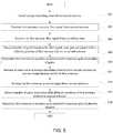
- FIG. 5is a flowchart for positioning a local antenna to find a signal from a remote antenna and achieve a desired gain and/or other signal characteristics in some embodiments.
- energy absorbing materialis installed on the remote second antenna.
- the energy absorbing materialmay be adhered or coupled to a receiving element of the remote second antenna.
- workersmay adhere the energy absorbing material to the receiving element of the remote second antenna to broaden a transmission radiation pattern of the remote second antenna.
- the first antennamay more easily detect a signal within the broader transmission radiation pattern.
- the energy absorbing materialmay be adhered or coupled to a receiving element of the local first antenna.
- workersmay adhere the energy absorbing material to the receiving element of the local first antenna to broaden a reception radiation pattern of the local first antenna.
- the first antennamay more easily detect a signal within the broader reception radiation pattern.
- some energy absorbing materialmay be added to both of the antennas.
- the first antennais positioned to receive a first signal from the second antenna.
- the first antennae.g., the receive element of the first antenna
- the second antennae.g., the receive element of the second antenna
- the first antennamay be positioned to search for a transmitted signal from the transmitting antenna.
- workersutilize a voltmeter at the first antenna to detect the signal from the second antenna.
- the first antennareceives the first signal from the second antenna.
- a signal from the second antennamay be detected at the first antenna.
- a position of the antennamay be marked and/or correlated with the strength of the signal (e.g., level of gain of the signal detected or level of another signal characteristic).
- the position of the antennamay represent a first position threshold.
- a plurality of gains associated with different positions by the first antenna relative to the second antennaare detected.
- the voltmetermay be used to detect different gains associated with different positions of the first antenna.
- the antennamay be repositioned to a position associated with the most desired detected signal propert(ies) (e.g., maximum gain).
- the position of the antennamay be marked and/or correlated with the strength of the signal.
- the position of the antennamay represent a second position threshold.
- the first antenna's positionmay be constrained by the first and/or second thresholds.
- the first antennais less likely to be adjusted in a position that moves away from the main beam of the second antenna.
- the thresholdsmay represent, in part, concentric circles in which the position of the first antenna may only be positioned within the narrowest concentric circle.
- the position of the first antennamay be limited by physical locks on a mounting bracket, physical limitations in the collar of the first antenna, thresholds, or any device or software.
- the first antennais repositioned to a position associated with maximum gain of the plurality of gains.
- the first positionmay be repositioned to a position associated with one or more desired signal characteristic(s) and/or avoidance of one or more undesired signal characteristic(s).
- the energy absorbing materialmay be removed from the second antenna to narrow transmission beamwidth of the second antenna. Any amount of the energy absorbing material may be removed.
- the beamwidth of the second antennamay be narrowed in any number of ways.
- the aperture of the second antennamay be mechanically narrowed (e.g., utilizing a shutter or other device). Further, obstructions may be utilized to limit the aperture and/or narrow the beamwidth.
- energy absorbing materialmay be removed from the first antenna to narrow a reception beamwidth of the first antenna.
- the first antennareceives a second signal from a second antenna.
- the first antennamay no longer be positioned to receive the second signal from the second antenna.
- the first antennamay be positioned based in part on the last position associated with desired signal characteristics of the previously received signal from the second antenna.
- a plurality of gainsor other signal characteristic(s) may be detected. The plurality of gains or other signal characteristics may be associated with different positions of the first antenna in step 516.
- the first antennais repositioned to a position associated with the most desired (e.g., maximum) gain or other signal characteristic.
- the first antennamay be repositioned based on the most desirable detected signal characteristic and the previous position.
- this processmay be iterated until a desired strength of a signal characteristic is attained. For example, there may be a minimum gain required by the two antennas over a given distance. Once a signal is detected by a first antenna at or above the minimum gain, the process may end. The process of repositioning the first antenna and/or narrowing a transmission or reception radiation pattern may repeat until the desired gain (or other signal characteristic is achieved.
- FIG. 6depicts a radio frequency unit 202 in some embodiments.
- the radio frequency unit 202may comprise mixer modules 602 and 616, filter modules 604, 608, 618, and 622, oscillator modules 606 and 620, a phase adjuster 610, an automatic gain control (AGC) module 612, amplification/attenuation modules 614 and 624, waveguide filter 626, and waveguide 628.
- the transmitting radio frequency unit 602may further comprise a signal quality module that may control the phase adjuster 610 and/or the AGC module 612.
- the radio frequency unit 202is a part of the ODU 408.
- the mixer module 602, filter module 604, and the oscillator module 606may represent an upconverter configured to upconvert the signal received from a gain module to an intermediate frequency signal.
- the mixer module 616, filter module 618, and oscillator module 620also may represent an upconverter configured to further upconvert the signal to an RF signal.
- the mixer modules 602 and 616may comprise mixers configured to mix the signal(s) provided by the modem with one or more other signals.
- the mixer modules 602 and 616may comprise many different types of mixers with many different electrical properties.
- the mixer 602mixes the signal received from a gain module (not shown) with the filtered oscillating signal from the filter module 604 and the oscillator module 606.
- the mixer module 616mixes a signal received from the amplifier/attenuator module 614 with the filtered oscillating signal from the filter module 618 and the oscillator module 620.
- each of the mixers 602 and 616may be the same as one or more other mixer modules.
- mixer modules 602 and 616may both be mixers sharing the same electrical properties or, alternately, the mixer 602 and 616 may be another kind of mixer and/or with different electrical properties.
- Each mixer modules 602 and 616may include one or more components.
- the mixer module 602may comprise one or more mixers.
- the filter modules 604, 608, 618, and 622may comprise filters configured to filter the signal.
- the filter modules 604, 608, 618, and 622may comprise many different types of filters (e.g., bandpass filter, low pass filter, high pass filter, or the like) with many different electrical properties.
- the filter module 604may be a band pass filter configured to filter the oscillation signal (or components of the signal) provided from the oscillator module 606.
- filter modules 604, 608, 618, and 622may filter signals (or components of the signals) from the oscillator module 606, the oscillator module 620, the mixer module 602, or the mixer module 616, respectively.
- each of the filter modules 604, 608, 618, and 622may be the same as one or more other filter modules.
- filters modules 604 and 608may both be filters sharing the same electrical properties while filter module 618 may be another kind of filter.
- filters module 604 and 608may both be filters of a similar type but have different electrical properties.
- Each filter modules 604, 608, 618, and 622may include one or more components.
- the filter modules 604may comprise one or more filters.
- the oscillator modules 606 and 620may comprise oscillators configured to provide an oscillating signal that may be used to upconvert the signal.
- the oscillator modules 606 and 620may comprise any kind of oscillator with any different electrical properties.
- the oscillator module 606provides an oscillating signal to the filter module 604.
- the oscillator module 620may provide an oscillating signal to the filter module 618.
- the oscillator modules 606 and 620may be local or remote.
- the oscillating module 606 and/or the oscillating module 620may be remotely located and configured to provide an oscillating signal to one or more transmitting radio frequency units.
- a single oscillating modulemay provide an oscillating signal to both the mixer module 602 and 616, respectively (e.g., optionally via a filter).
- the oscillator signal from the oscillator modulemay be altered (e.g., oscillation increased or decreased) and provided to a different part of the circuit.
- each of the oscillator modules 606 and 620may be the same as each other.
- oscillator modules 606 and 620may both be oscillators sharing the same electrical properties or, alternately, the oscillator modules 606 and 620 may be another kind of oscillator and/or with different electrical properties.
- Each oscillator modules 606 and 620may include one or more components.
- the oscillator module 606may comprise one or more oscillators.
- the radio frequency unit 202includes a signal quality module.
- the signal quality modulemay be configured to generate a phase control signal to control the phase of a processed signal.
- the signal quality modulereceives the upconverted RF signal from the amplifier/attenuator module 624 and mixes the amplified or attenuated signal with the filtered oscillator signal or the upconverted signal from the second upconverter.
- the signal quality modulemay filter the signal and compare the filtered, mixed signal with a predetermined phase value to generate a phase control signal based on the comparison.
- the phase adjuster 610may comprise a variable phase control circuit configured to increase or decrease the phase of the signal to be transmitted.
- the phase adjuster 610may comprise any different type of phase adjuster or phase shifter with different electrical properties.
- the phase adjuster 610increases or decreases the phase of the signal received from the filter module 608.
- the phase adjuster 610may adjust the phase of the signal based on the phase control signal from the signal quality module.
- the phase adjuster 610may include one or more components.
- the phase adjuster 610may comprise one or more phase control elements.
- the AGC module 612may comprise an automatic gain control (AGC) circuit configured to increase or decrease the gain of the signal received from the phase adjuster 610.
- AGCautomatic gain control
- the AGC module 612may comprise many different types of AGCs with many different electrical properties. In one example, the AGC module 612 increases or decreases the gain of the signal received from the phase adjuster 610.
- the AGC module 612may adjust the gain of the signal based on the gain control signal.
- the AGC module 612may include one or more components.
- the AGC module 612may comprise one or more AGCs.
- the signal quality modulemay provide control signals to adjust the filtered signal from the filter module 608 to achieve the desired adjustment. For example, in order to adjust the phase or amplitude of the signal, the signal quality module may compare the phase and amplitude of the signal to be provided to the waveguide filter 626 and/or the waveguide 628 based on a predetermined phase value and/or a predetermined amplitude value. Based on the comparison, the signal quality module may generate phase and gain control signals to achieve the desired adjustment.
- the predetermined phase value and amplitude valuemay be the same or substantially similar as the phase and amplitude of the wireless signals outputted by one or more other transmitting radio frequency units.
- the phase and the amplitude of one or more transmitting radio frequency unitmay be synchronized.
- the amplification/attenuation modules 614 and 624may comprise an amplifier and/or an attenuator configured to amplify and/or attenuate a signal.
- the amplification/attenuator modules 614 and 624may be any kind of amplifiers and/or attenuators. Further, the amplification/attenuator modules 614 and 624 may each comprise amplifiers and/or attenuators with any kind of electrical properties.
- the amplifier/attenuator module 614receives a signal from the AGC module 612.
- the amplifier/attenuator module 614may amplify or attenuate the signal.
- the amplifier/attenuator module 624may attenuate the signal (or components of the signal) after the signal has been upconverted by the mixer module 616, the filter module 618, and the oscillator module 620.
- the amplifier/attenuator module 624may then provide the signal to the signal quality module and/or the waveguide filter 626.
- each of the amplifier/attenuator modules 614 and 624may be the same as one or more other amplifier/attenuator modules.
- amplifier/attenuator modules 614 and 624may both be amplifiers sharing the same electrical properties.
- amplifier/attenuator modules 614 and 624may both be amplifiers but have different electrical properties.
- the radio frequency unit 202may comprise the waveguide filter 626 and the waveguide 628.
- the waveguide filter 626may be any filter coupled to the waveguide 628 and configured to filter the electromagnetic waves (e.g., remove noise).
- the waveguide 628may provide the signal to an antenna via a diplexer.
- the diplexermay provide the signal to the antenna.
- the waveguide 628may be any waveguide kind or type of waveguide.
- the waveguide 628may be hollow or dielectric.
- the waveguide 628comprises a rectangular to circular waveguide.
- the signal detection and/or detection of signal characteristicsmay occur at any point.
- a voltmeterdetects a signal received by an antenna by measuring voltage at the IF frequency.
- FIG. 7depicts an exemplary digital device 700 according to some embodiments.
- the digital device 700comprises a processor 702, a memory system 704, a storage system 706, a communication network interface 708, an I/O interface 710, and a display interface 712 communicatively coupled to a bus 714.
- the processor 702may be configured to execute executable instructions (e.g., programs).
- the processor 702comprises circuitry or any processor capable of processing the executable instructions.
- the memory system 704is any memory configured to store data. Some examples of the memory system 704 are storage devices, such as RAM or ROM. The memory system 704 may comprise the RAM cache. In various embodiments, data is stored within the memory system 704. The data within the memory system 704 may be cleared or ultimately transferred to the storage system 706.
- the storage system 706is any storage configured to retrieve and store data. Some examples of the storage system 706 are flash drives, hard drives, optical drives, and/or magnetic tape.
- the digital device 700includes a memory system 704 in the form of RAM and a storage system 706 in the form of flash data. Both the memory system 704 and the storage system 706 comprise computer readable media which may store instructions or programs that are executable by a computer processor including the processor 702.
- the communication network interface (com. network interface) 708may be coupled to a data network (e.g., data network 164 or 1114) via a link.
- the communication network interface 708may support communication over an Ethernet connection, a serial connection, a parallel connection, or an ATA connection, for example.
- the communication network interface 708may also support wireless communication (e.g., 802.11 a/b/g/n, WiMAX). It will be apparent to those skilled in the art that the communication network interface 708 may support many wired and wireless standards.
- the optional input/output (I/O) interface 710is any device that receives input from the user and output data.
- the optional display interface 712is any device that may be configured to output graphics and data to a display. In one example, the display interface 712 is a graphics adapter.
- a digital device 700may comprise more or less hardware elements than those depicted. Further, hardware elements may share functionality and still be within various embodiments described herein. In one example, encoding and/or decoding may be performed by the processor 702 and/or a coprocessor located on a GPU.
- a digital devicemay be coupled to the voltmeter or other meter to detect a signal, detect one or more signal characteristics associated with the signal, track one or more positions of the receiving antenna and/or transmission antenna, and/or associate the one or more positions of the receiving antenna and/or transmission antenna with the detected one or more signal characteristics.
- the digital devicemay make recommendations or control the receiving antenna based on detected signals, signal characteristics and past positioning to attain the desired position. As the aperture of the receiving or transmitting antennas is broadened and the radiation pattern narrowed, the digital device may search for a subsequent signal from the transmitting antenna by moving or making recommendations to move the receiving antenna until: 1) the subsequent signal is detected; and 2) the strongest or desired signal characteristics are attained.
- the digital devicemay include a series of thresholds and may move or make recommendations to move the receiving element of the receiving antenna until a signal characteristic is at or above one or more thresholds. Further, the digital device may track the most likely receiving and/or transmission radiation patterns and make more accurate recommendations of moving or repositioning the receiving antenna based at least in part on the likely radiation patterns.
- the digital devicemay move the receiver element and/or receiving antenna through servos and/or motors (e.g., at the mounting bracket).
- the above-described functions and componentsmay be comprised of instructions that are stored on a storage medium such as a non-transitive computer readable medium.
- the instructionsmay be retrieved and executed by a processor.
- Some examples of instructionsare software, program code, and firmware.
- Some examples of storage mediumare memory devices, tape, disks, integrated circuits, and servers.
- the instructionsare operational when executed by the processor to direct the processor to operate in accord with some embodiments. Those skilled in the art are familiar with instructions, processor(s), and storage medium.
Landscapes
- Engineering & Computer Science (AREA)
- Physics & Mathematics (AREA)
- Computer Networks & Wireless Communication (AREA)
- Signal Processing (AREA)
- Electromagnetism (AREA)
- Quality & Reliability (AREA)
- General Physics & Mathematics (AREA)
- Variable-Direction Aerials And Aerial Arrays (AREA)
- Position Fixing By Use Of Radio Waves (AREA)
- Mobile Radio Communication Systems (AREA)
- Aerials With Secondary Devices (AREA)
Description
- The present invention(s) relate to wireless network systems, and more particularly, to systems and methods of antenna orientation in a point-to-point wireless network.
- Wireless antenna systems, such as microwave antenna system, are increasingly common. Large amounts of information may be transmitted at high frequencies between antennas. Point-to-point antenna systems are often used to increase, increase other desirable signal characteristics, and/or allow greater distances between antennas.
- In one example, e-band wireless systems may offer full-duplex gigabit Ethernet connectivity at data rates of 1 Gbps and higher. The e-band includes 71-76 and 81-86 GHz bands. Since gain of an antenna increases with frequency, it is possible to realize large gains from small antennas at e-band frequencies. For example, at the e-band of a 30 cm parabolic antenna has a gain of 44 to 45 dBi. An extra 24 dB allows for a significant distance increases between antennas.
- Unfortunately, as distances between antennas increase, the difficulty of aligning one or both antennas to achieve point-to-point communication also increases. Weather or other external events may influence gain and/or other signal characteristics. In one example, weather may negatively affect e-band wireless systems resulting to link fading. The degree and severity of link fading may depend on weather type, severity, distances between antennas, type of antennas, gain demands, and the like. As with any radio transmission above 10 GHz, rain leads to significant attenuation of signals. For example, different amounts of rainfall may attenuate the signal from 10 dB/km to 30 dB/km. As a result, rainfall and other weather conditions may limit the distances between antennas.
- Further, visibility may be impacted by pollution, fog, smoke, or the like making positioning an antenna using line-of-sight difficult. It is not uncommon that optical alignment accessories are used to correctly align antennas. In one example, a monocular may be coupled to an antenna to assist in antenna alignment and/or orientation. Alternatively, mirrors and lasers have been used to assist in alignment. Unfortunately, pollution or other obstructions that limit visibility (even if there is no impact on signal quality) may limit the effectiveness of optical alignment. Further, even if air conditions are clear and optical tools are utilized, the installer needs to know exact location of the remote site which can be very challenging in an urban environment.
- Prior publication
EP1659813 A1 refers to a communication system and method in which first and second stations are adapted to automatically establish at least one alternative communication part for wireless communication via narrow beam antennas. US Statutory Invention Registration H1034 refers to a millimetre wave Cassegrain antenna for a seeker missile.US 3,364,490 teaches a variable beam width antenna utilising defocusing relating to variable beam width double-reflector mono pulse antennas.US 7,663,560 refer to a satellite system having an outdoor unit that has a low noise black (LNB) and having an antenna that relies on using a microwave energy absorbing cap. - An exemplary method comprises positioning a first antenna to receive a first signal from a second antenna, the second antenna comprising energy absorbing material that functions to expand beamwidth, receiving the first signal from the second antenna, detecting a plurality of gains based on the first signal, repositioning the first antenna relative to the second antenna to a position associated with an acceptable gain based on the first signal, removing at least some of the energy absorbing material from the second antenna to narrow the beamwidth of the second antenna, receiving, by the first antenna, a second signal from the second antenna, detecting a plurality of gains based on the second signal, and repositioning the first antenna relative to the second antenna to a position associated with an increased gain of the plurality of gains based on the second signal, the increased gain being greater than the acceptable gain.
- In various embodiments, repositioning the first antenna relative to the second antenna to the position associated with the acceptable gain of the plurality of gains based on the first signal may comprise positioning the first antenna based on a maximum gain detected of the plurality of gains. Detecting the plurality of gains based on the first signal, each gain associated with the different position of the first antenna relative to the second antenna may comprise detecting the plurality of gains associated with different positions of the first antenna relative to the second antenna until detection of the acceptable gain, the acceptable gain being above a first predetermined threshold.
- The method may further comprise measuring a voltage associated with the first signal to detect the plurality of gains associated with different positions of the first antenna relative to the second antenna. In some embodiments, the energy absorbing material narrows an aperture of the second antenna to broaden the beamwidth of the second antenna. The energy absorbing material may be adhered to the second antenna and removed from the second antenna by peeling the at least some of the energy absorbing material from the second antenna.
- In various embodiments, repositioning the first antenna relative to the second antenna to the position associated with the increased gain of the plurality of gains based on the second signal, the increased gain being greater than the acceptable gain of the plurality of gains based on the first signal, may comprise repositioning the first antenna relative to the second antenna based on the maximum gain of the plurality of gains based on the second signal. Detecting the plurality of gains based on the second signal, each gain associated with the different position of the first antenna relative to the second antenna may comprise detecting the plurality of gains associated with different positions of the first antenna relative to the second antenna until detection of the increased gain, the increased gain being above a second predetermined threshold.
- In some embodiments, the method may further comprise receiving, by the second antenna, a third signal from the first antenna, detecting a plurality of gains associated with different positions of the second antenna relative to the first antenna, and repositioning the second antenna relative to the first antenna to adjust a detected gain of the third signal. Further, the method may also comprise removing at least some of energy absorbing material from the first antenna to narrow a beamwidth of the first antenna, receiving, by the second antenna, a fourth signal from the first antenna, detecting a plurality of gains based on the fourth signal, each gain associated with a different position of the second antenna relative to the first antenna, and repositioning the second antenna relative to the first antenna to a position associated with an increased gain of the plurality of gains based on the fourth signal, the increased gain being greater than the acceptable gain of the plurality of gains based on the third signal.
- An exemplary system comprises a first antenna and a meter. The first antenna may be configured to be positioned to receive a first signal from a second antenna, the first antenna comprising energy absorbing material, the energy absorbing material enabling expansion of a beamwidth of the first antenna, the first antenna configured to be repositioned relative to the second antenna based on an acceptable gain of the first signal, to be positioned to receive a second signal from the second antenna, at least some of the energy absorbing material being removed from the first antenna prior to reception of the second signal, the first antenna configured to be repositioned relative to the second antenna based on an increased gain of the second signal, the increased gain being greater than the acceptable gain of the plurality of gains based on the first signal. The meter coupled to the first antenna and configured to determine if a detected gain of the first signal is greater than or equal to the acceptable gain and to determine if a detected gain of the second signal is greater than or equal to the increased gain.
- Another exemplary embodiments comprises positioning a first antenna to receive a first signal from a second antenna, the first antenna comprising energy absorbing material that functions to expand beamwidth of the first antenna, receiving, by the first antenna, the first signal from the second antenna, detecting a plurality of gains based on the first signal, each gain associated with a different position of the first antenna relative to the second antenna, repositioning the first antenna relative to the second antenna to a position associated with an acceptable gain of the plurality of gains based on the first signal, removing at least some of the energy absorbing material from the first antenna to narrow the beamwidth of the first antenna, receiving, by the first antenna, a second signal from the second antenna, detecting a plurality of gains based on the second signal, each gain associated with a different position of the first antenna relative to the second antenna, and repositioning the first antenna relative to the second antenna to a position associated with an increased gain of the plurality of gains based on the second signal, the increased gain being greater than the acceptable gain of the plurality of gains based on the first signal.
- An exemplary system comprises a first antenna and a meter. The first antenna may be configured to be positioned to receive a first signal from a second antenna, the second antenna comprising energy absorbing material, the energy absorbing material enabling expansion of a beamwidth of the second antenna, the first antenna configured to be repositioned relative to the second antenna based on an acceptable gain of the first signal, to be positioned to receive a second signal from the second antenna, at least some of the energy absorbing material being removed from the second antenna prior to reception of the second signal, the first antenna configured to be repositioned relative to the second antenna based on an increased gain of the second signal, the increased gain being greater than the acceptable gain of the plurality of gains based on the first signal. The meter may be coupled to the first antenna and configured to determine if a detected gain of the first signal is greater than or equal to the acceptable gain and to determine if a detected gain of the second signal is greater than or equal to the increased gain.
- Other features and aspects of various embodiments will become apparent from the following detailed description, taken in conjunction with the accompanying drawings, which illustrate, by way of example, the features of the various embodiments.
FIG. 1 depicts a local antenna in communication with a remote antenna in some embodiments.FIG. 2 is a diagram depicting a transmitting antenna and a receiving antenna in some embodiments.FIGs 3a-c depict antennas which may be coupled to varying amounts of energy absorbing material to decrease aperture of the antennas in some embodiments.FIG. 4 is an environment including a transceiver unit in some embodiments.FIG. 5 is a flowchart for positioning a local antenna to find a signal from a remote antenna and achieve a desired gain and/or other signal characteristics in some embodiments.FIG. 6 depicts a radio frequency unit in some embodiments.FIG. 7 depicts an exemplary digital device according to some embodiments.FIG. 1 depicts alocal antenna 102 in communication with aremote antenna 104 in some embodiments. Thelocal antenna 102 andremote antenna 104 may be any type of antenna including, for example, a parabolic antenna (e.g., aperture antenna). A parabolic antenna is an antenna that uses a parabolic reflector to direct radio waves. An exemplary parabolic antenna may comprise a reflector element and a feed antenna. The reflector element may be made of many different types of material and may be any shape (e.g., circular dish, rectangular, or the like). The feed antenna is typically at the reflector's focus and is a low-gain type antenna. Those skilled in the art will appreciate that thelocal antenna 102 and theremote antenna 104 may be any kind of antennas.- Many antennas, especially those in the e-band, utilize point-to-point transmission systems to obtain necessary gain and/or other desired signal characteristics over significant distances. Directing a radiation pattern with a narrow beamwidth from a transmitting antenna (e.g., transmitting effectiveness) and/or a receiving antenna (e.g., receiving effectiveness) in a point-to-point wireless network allows for increased gain or other improved signal characteristics. Obtaining greater gain and/or other improved signal characteristics may increase reliability in poor weather conditions and may also allow for the receive and transmission antennas to be spaced further apart. Unfortunately, as the distance between the two antennas increase and the beamwidths of one or both radiation patterns of the antennas narrows, it becomes increasingly difficult to position each antenna such that each antenna detects a signal from the other. Even if a receiving antenna is generally positioned relative to the transmitting antenna, it remains difficult to adjust the orientation and position of the receiving antenna to reliably improve or maximize gain or other signal characteristics.
- When a receiving antenna is a significant distance from a transmitting antenna and the transmitting antenna is transmitting a pencil beam radiation pattern, the two antennas are typically positioned to allow the pencil beam to be directed to the receiving antenna such that the receiving antenna may receive a signal from the transmitting antenna. Considerable time may be wasted as the antennas are adjusted until the receiving antenna is within the radiation pattern of the transmitting antenna. Typically, workers at the receiving antenna and workers at the transmitting antenna move the antenna elements (e.g., the "dish") such that a signal from the transmitting antenna may be received by the receiving antenna. If a signal is detected, then the receiving antenna may be further oriented or repositioned to maximize gain or other signal characteristics of the signal (e.g., adjusting position of the receiving element of the receive antenna). The transmitting antenna may also be oriented to improve gain at the receiving antenna.
- In one example, millimeter wave point-to-point antennas may have a 3 dB beamwidth of 1.2 degrees (e.g., gain of 43dBi for 30cm dish antenna at 80GHz - a typical type of antenna for E-band point-to-point applications). If the initial antenna orientation is within +1-6 degrees in azimuth and elevation of the correct direction, there may be 10 discrete orientation positions for each polarization (e.g., 100 direction spots in AZ-EL plane). In case the link fade margin is below antenna sidelobe levels (typical SLL are >30dB), the time to align the antennas can be very high.
- Much faster antenna orientation can be achieved by temporary widening the antenna beamwidth (e.g., with beamwidth of 3.6 degrees). In this example, the antenna orientation may be much faster while still feasible as the antenna gain may reduce less than the link fade margin (e.g., 2 x 9.5dB).
- Antenna alignment may involve adjusting the direction of each antenna until the received signal strength reaches a desired or maximum level at each end of the link. Fine adjustment for azimuth (horizontal angel) and elevation (vertical angel) may be built into each antenna mount. Adjustment procedures may be provided with each antenna.
- If the horizontal adjuster does not provide sufficient range to locate the main beam, the antenna mounting brackets may need to be loosened and the antenna swiveled on its pole mount to locate the beam. Some mounts for larger antennas may have a separately clamped swivel base to allow the loosened antenna to swivel on it without fear of slipping down the pole. Where such a mount is not provided a temporary swivel clamp may be provided using a pair of pipe brackets bolted together immediately below the antenna mount.
FIG. 2 is a diagram depicting a transmittingantenna 202 and a receivingantenna 204 in some embodiments. In various embodiments, the transmittingradiation pattern 206 of the transmittingantenna 202 may be broadened (e.g., the beamwidth of the transmitting radiation pattern broadened) such that the receivingantenna 204 may more easily be positioned to detect a signal from the transmitting antenna. Once the signal from the transmittingantenna 202 is detected, the receivingantenna 304 may be further oriented or repositioned such that the receivingantenna 304 may maximize or receive a desired gain and/or other characteristic of the signal. Similarly, the transmittingantenna 202 may also be repositioned such that the receivingantenna 204 receives a signal with maximum gain or other characteristic.- Those skilled in the art will appreciate that the receiving
antenna 204 may be more easily positioned and repositioned to find a signal from the transmittingantenna 202 when the transmittingradiation pattern 206 is broader. In one example, a signal may be more easily detected by generally directing the receivingantenna 204 towards the transmittingantenna 202. Once the signal from the transmittingantenna 202 is detected, minor adjustments to the orientation and/or position may be made to find a maximum gain or a gain above a predetermined threshold (e.g., above an acceptable gain). Those skilled in the art will appreciate that any signal characteristics, not just gain, may be used. For example, adjustments to the receivingantenna 204 may be performed to maximize desirable signal characteristics and/or minimize undesirable signal characteristics. - Subsequently, in order to achieve a final desired gain and/or other signal characteristics, the transmitting radiation pattern from the transmitting
antenna 202 may be narrowed (e.g., a pencil beam is directed from the transmittingantenna 202 to the receiving antenna 204). Since the receivingantenna 204 is already oriented towards the transmittingantenna 202, the receivingantenna 204 may more easily find subsequent signals from the transmittingantenna 202. Once the subsequent signals from the transmittingantenna 202 is detected, the receivingantenna 202 may, again, be adjusted to maximize gain or gain above a second predetermined threshold (e.g., above an increased gain, the increased gain being greater than the acceptable gain). As discussed herein, adjustments to the receivingantenna 204 may be performed to maximize desirable signal characteristics and/or minimize undesirable signal characteristics of the subsequent signals. - Those skilled in the art will appreciate that the process may be iterative. For example, the process may continue as the radiation beam associated with the transmitting antenna is repeatedly narrowed after the receiving antenna detects a signal from the transmission antenna and the position adjusted to achieve the desired or expected characteristics. At each stage, the receiving
antenna 204 and/ortransmission antenna 202 may be repositioned to more easily direct the signal to the desired destination. Once a position is found (e.g., a position that maximizes gain or achieves a desired performance of a signal characteristic of a received signal), the beamwidth of the transmitting antenna, for example, may be subsequently narrowed. The receiving antenna, being already in a position that is proximate to the desired position as a result of the previous adjustment(s), may be repositioned to detect the signal at the desired gain or other signal characteristic. - In various embodiments, antenna alignment involves adjusting a direction (e.g., elevation, vertical, and/or horizontal position) for an antenna until the received signal strength reaches a maximum or desired level at each end of the link. Fine adjustment for azimuth (e.g., horizontal angle) and elevation (e.g., vertical angle) may be built into an antenna mount. In some embodiments, if the horizontal adjuster does not provide sufficient range to locate the main beam, antenna mounting brackets may be adjusted to locate the main beam.
- In various embodiments, the beamwidth of an antenna may be altered by coupling the reflector element (or other element) of the antenna with energy absorbing materials. The energy absorbing material may be coupled to the antenna in any number of ways including, for example, adhesively or with a mechanical means (e.g., clips, staples, clamps, or the like). The functional effect of coupling the antenna to energy absorbing material may be to reduce the aperture of the antenna, thereby increasing the beamwidth of the associated radiation pattern. The energy absorbing materials are further discussed herein. Although some embodiments discussed herein include examples of expanding or broadening a radiation patter of a related antenna, those skilled in the art will appreciate that the radiation pattern may be broadened in any number of ways.
- Gain, aperture, and beamwidth are related. For example, gain is a directive quality of an antenna and is a ratio of the power received by the antenna from a source along its beam axis to the power received by a hypothetical isotropic antenna. One equation regarding the gain of a parabolic antenna is as follows:

- A is the area of the antenna aperture, that is, the mouth of the parabolic reflector
- d is the diameter of the parabolic reflector, if it is circular
- λ is the wavelength of the radio waves.
- eA is a dimensionless parameter between 0 and 1 called the aperture efficiency. The aperture efficiency of typical parabolic antennas is 0.55 to 0.70.
- As discussed herein, in aperture antennas, the larger the aperture (compared to the wavelength), the higher the gain. The gain increases with the square of the ratio of aperture width to wavelength.
- The angular width of the beam radiated by an aperture antenna may be measured by half-power beamwidth (HPBW) which is the angular separation between points on the antenna radiation pattern at which the power drops to one-half (-3 dB) its maximum value. For parabolic antennas, the HPBWθ is given by:

- There is an inverse relation between gain and beamwidth. By combining the beamwidth equation with the gain equation, the relation is:

- The Friis equation gives the power received by one antenna under idealized conditions given another antenna a given distance away transmitting a known amount of power.
- The inverse of the factor in parentheses is the so-called free-space path loss. To use the equation as written, the antenna gain maynot be in units of decibels, and the wavelength and distance units must be the same. If the gain has units of dB, the equation is slightly modified to:

- (Gain has units of dB, and power has units of dBm or dBW)
whereGt andGr are the antenna gains (with respect to an isotropic radiator) of the transmitting and receiving antennas respectively,λ is the wavelength, andR is the distance between the antennas. This form of the Friis equation applies under the following ideal conditions: - R ≫λ(reads asR much greater thanλ).
- The antennas are in unobstructed free space.
- Pr is understood to be the available power at the receive antenna terminals.
- Pr is understood to be the power delivered to the transmit antenna.
- The antennas are correctly aligned and polarized.
- The bandwidth is narrow enough that a single value for the wavelength can be assumed.
- To detect a desired gain or other signal characteristic, in some embodiments, a Received Signal Level (RSL) is monitored and the alignment of the receiving antenna is adjusted to maximize RSL. The RSL may be monitored at several alignment orientations of the receiving antenna. The receiving antenna may be oriented to a position associated with a maximum monitored RSL or a RSL that is above an expected threshold. The transmission beamwidth of the transmitting antenna may be narrowed and the process repeated (e.g., adjusting a position of or repositioning the receiving antenna to detect a signal, monitoring RSL at several alignment orientations of the receiving antenna, and orienting the receiving antenna to a position associated with a maximum RSL or a RSL that is above another expected threshold). The process may be repeated until the desired beamwidth of the transmission system, gain of the received signal, and/or other characteristic(s) of the received signal are obtained. In some embodiments, this process may be repeated at the far end of the link (e.g., the transmitting antenna may be adjusted and/or oriented to maximize gain or other characteristic(s) of a signal from the previously receiving antenna).
- In one example of locating the main beam of an antenna, once a measurable signal is observed, very small alignment adjustments may be required to locate the main beam. For example, a 1.2m antenna at 23 GHz typically has 0.9° of adjustment from center of main beam to the first null (0.4° to the -3 dB point). Antenna movement across the main beam will result in a rapid rise and fall of signal level. As a guide, 1 degree of beam width may be equivalent to moving approximately 1.0 mm around a standard 114 mm (4.5 in.) diameter O/D pipe. Antennas may be verified as being on main beam (as opposed to a side lobe) by comparing measured receive signal level with the calculated level. Signal strength readings are usually measurable when at least a main beam at one end and first side lobes at the other are aligned. The strongest signal occurs at the center of the main beam. The highest first lobe signal is typically 20-25 dB less than the main beam signal. When both antennas are aligned for maximum main beam signal strength, the receive signal level (RSL) should be within 2 dB of the calculated level for the path.
- RSL, RSSI, or any characteristic or combination of characteristics of the signal may be monitored to adjust the orientation of the receiving antenna. In one example, a voltmeter, such as a multimeter, may be used to measure the RSSI voltage at an outdoor unit (e.g., the ODU of
FIG. 4 ) coupled to the antenna. In one example, antenna alignment may be adjusted until the voltmeter indicates a minimum or sufficiently low value. In one example, a plurality of detected RSSI voltages are detected as the receiving antenna is aligned and realigned. The lowest detected RSSI voltage of the plurality of voltages may be selected and the receiving antenna may be aligned with a position associated with the lowest detected RSSI voltage. In another example, a measured RSSI voltage at the ODU may be compared to a predetermined threshold. The receiving antenna may be aligned until the RSSI voltage is at or below the predetermined threshold. In yet another example, the antenna may be realigned until the detected RSSI voltage is within a range (e.g., statistically close) to a desired RSSI voltage. - Those skilled in the art will appreciate that the antenna may be realigned based on the detected RSSI voltage in many ways. In various embodiments, the RSSI voltage provides a direct relationship with RSL. For example, an RSSI of 0.25 Vdc=-10dBm decrease in RSL. (See table RSL - voltage at BNC - so for a voltage at BNC (Vdc), there is a commiserate RSL (dBm).
- This procedure could be improved by providing a locking mechanism on the mounting mechanics. For example, after finding the correct position of the receiving
antenna 204 with the most wide radiation beamwidth, the mechanical mechanism used for rotating the receivingantenna 204 may be locked for the next diaphragm beamwidth so that antenna could not be mechanically oriented outside spatial region dictated by the current diaphragm beamwidth. - In case link hop length is very long (moderate link fade margin) the receiver sensitivity may be increased by the use of single tone (CW) transmitted signal rather than a wideband modulated signal used only during antenna alignment procedure. As much as 20dB receiver sensitivity could be gained using this approach (200MHz modulated signal for typical E band application using the narrowest channel versus 2MHz receiver resolution bandwidth for CW reception).
- Although the discussion regarding
FIG. 2 contemplates changing the radiation pattern (e.g., a transmission radiation pattern) of the transmittingantenna 202, those skilled in the art will appreciate that instead of changing the radiation pattern of the transmittingantenna 202, the radiation pattern (e.g., a receptivity radiation pattern) of the receivingantenna 202 may be changed. For example, the radiation pattern of the receivingantenna 202 may be initially broadened (e.g., by coupling the receiving element of the receivingantenna 202 with energy absorbing material to narrow the aperture). After the receivingantenna 202 detects the signal from the transmittingantenna 202, the receivingantenna 202 may be adjusted to achieve an acceptable gain and/or other signal characteristic. Subsequently, some if not all of the energy absorbing material may be removed and the receivingantenna 202 may be positioned to detect a subsequent signal from the transmittingantenna 202. After detection of the subsequent signal, the receivingantenna 204 may be repositioned to achieve another desired acceptable gain and/or other signal characteristic. This process may be repeated until the final gain (e.g., an increased gain) or other signal characteristic is attained. - Those skilled in the art will appreciate that the radiation pattern of both the transmitting
antenna 202 and the receivingantenna 204 may be broadened and subsequently narrowed. In some embodiments, the radiation pattern of both the transmittingantenna 202 and the receivingantenna 204 may be narrowed simultaneously or near simultaneously (e.g., by removing at least some energy absorbing material from both antennas). In various embodiments, some energy absorbing material may be removed from one antenna and, after repositioning, some energy absorbing material may be removed from the other antenna. Those skilled in the art will appreciate that the radiation pattern in both antennas may be broadened and narrowed in any way at any time. FIGs 3a-c depictantennas 302 which may be coupled to varying amounts of energy absorbing material to decrease aperture of theantennas 302 in some embodiments. In various embodiments, diaphragms of different openings made of appropriate absorbing material to control the antenna radiation beamwidth during the link setup may be used to assist in the process of finding signals from remote antennas and adjusting a local antenna position to increase gain of received signals. For example, three different diaphragms could be used with 3dB beamwidths of 12, 6, and 3 degrees, respectively. Those skilled in the art will appreciate that any number of diaphragms may be used which may be stripped off the antenna to change a radiation pattern.- Diaphragms may be made of a thin sheet absorbing material and attached to the antenna rim. In some embodiments, after finding a maximum signal level for the most wide beamwidth (diaphragm with narrowest opening), this diaphragm may be removed and the next diaphragm would allow for a wider aperture when compared to the antenna without the diaphragm but still a more narrow aperture when compared to the previous aperture of the antenna (i.e., before any of the diaphragm was removed).
- In one example, the energy absorbent material may be a thin, flexible flat sheet configured to adhere to a part of the antenna (e.g., across all or apportion of the aperture of an aperture antenna). The energy absorbent material may include one or more dielectric loaded silicone rubber sheets. The energy absorbent material may be any dimension or thickness. Those skilled in the art will appreciate that any energy absorbing material may be used. For example, Eccosorb DSF free space resonant absorbers from Emerson & Cuming Microwave Products ™, Q-Zorb RFSB single band absorber from Laird Technologies ™, Q-Zorb RFSW surface wave absorber from Laird Technologies ™, or the like may be used. Any adherent maybe used including RTV silicone based adhesives with or without a primer, or the like. In some embodiments, the energy absorbent material may be coupled to the antenna through the use of mechanical fasteners or the like.
- In various embodiments, the
antenna 302 is directed to a remote antenna. The energyabsorbent material antenna 302 thereby allowing the remote antenna to more easily find a signal from the remote antenna and be oriented to thereby increase the gain (e.g., RSL) associated with the signal. After the remote antenna is positioned and adjusted to receive the desired and/or maximum gain of the signal, energyabsorbent material 308 may be removed (e.g., peeled off of the antenna by a worker) thereby increasing the functional aperture of theantenna 302 and decreasing the beamwidth. Alternately, the energyabsorbent material antenna 302 to allow the remote antenna t more easily find a signal from theantenna 302. - In various embodiments, the energy
absorbent material 308 is the same material as the energyabsorbent material 310. In other embodiments, the energyabsorbent material 308 is not the same material as the energyabsorbent material 310. FIG. 3a depicts anantenna 302 with energyabsorbent material antenna 302 in some embodiments.Antenna 302 comprises aparabolic reflector 304 and afeed antenna 306. Theparabolic reflector 304 is blocked, at least partially, by the energyabsorbent material absorbent material antenna 302 and thereby broadens the transmission/reception radiation pattern of the antenna 302 (e.g., broadens the half-power beamwidth (HPBW)).FIG. 3b depicts an energyabsorbent material 310 covering a portion of theantenna 302 in some embodiments. Since the energyabsorbent material 310 covers a smaller portion of theparabolic reflector 304, the functional aperture of theantenna 302 is greater than that discussed with regard toFIG. 3a . The resulting transmission/reception radiation of theantenna 302 is broader than an antenna with similar characteristics asantenna 302 but without the energyabsorbent material 310. Further, the resulting transmission/reception radiation of theantenna 302 is smaller than the resulting transmission/reception radiation of theantenna 302 as depicted inFIG. 3a .- As discussed herein, once the remote antenna has been oriented to a desired and/or maximum gain based on the smaller functional aperture of the
antenna 302 associated withFIG. 3a , energyabsorbent material 308 may be removed from theantenna 302 thereby increasing the functional aperture of theantenna 302 and decreasing the beamwidth. The energyabsorbent material 310 continues to function to broaden the beamwidth of the antenna 302 (when compared to an antenna with less or without any energy absorbent material) thereby allowing the remote antenna to more easily find a signal from theantenna 302 and be oriented to thereby increase the gain (e.g., RSL) associated with the signal. After the remote antenna is positioned and repositioned to receive the desired and/or maximum gain of the signal, energyabsorbent material 310 may be removed (e.g., peeled off of the antenna by a worker) thereby further increasing the functional aperture of theantenna 302 and further decreasing the beamwidth. FIG. 3c depicts theantenna 302 without the energy absorbent material in some embodiments. Theparabolic reflector 304 may provide the narrowest beamwidth of transmission/radiation patterns in comparison with the antennas ofFIG. 3a and 3b . In a manner similarly discussed regardingFIGs 3a and 3b , the remote antenna may be again repositioned to find the signal from theantenna 302 and then be adjusted to receive the desired and/or maximum gain of the signal.- Although the discussion regarding
FIGs 3a-3c contemplate removal of two separate portions of energyabsorbent material antenna 302 and the process may continue. - Although
FIGs 3a-c depict the removal of all energy absorbent materials from theantenna 402, any amount of energy absorbent materials may remain coupled to theantenna 302 at any time. For example, if a final desired gain or other characteristic of a signal is obtained, the energy absorbent materials may be left coupled to theantenna 302. - Although the discussion regarding
FIGs 3a-c energy absorbent materials coupled to a transmittingantenna 302, those skilled in the art will appreciate that the energy absorbent material may be coupled to a receiving antenna. As a result, the reception radiation pattern may be broadened to more easily find signals from the transmitting antenna. The iterative process of finding a signal from the transmitting antenna, adjusting the position of the receiving antenna for improved gain, removing some of the energy absorbent material from the receiving antenna may continue in a manner similar to that described herein. FIG. 4 is anenvironment 400 including atransceiver unit 402 in some embodiments. Thefrequency radio unit 402 is a split mount radio. A split-mount radio has a part of the electronics mounted outdoors with an antenna and part indoors. The outdoor unit (ODU) may be the RF transmitter/receiver. The indoor unit (IDU) contains the modulator/demodulator, multiplexer, control, and traffic interface elements. The IDU and ODU may be coupled using a cable. By comparison, an all-indoor radio has all radio equipment installed inside and is connected to its antenna using a waveguide or coax feeder. A split-mount radio may be a point-to-point radio installation for licensed 6 to 38+ GHz frequency bands with the ODU direct-mounted to the rear of the antenna to provide an integral antenna feed. By having the ODU mounted with the antenna, split-mount may eliminate or reduce feeder losses, minimize or reduce rack occupancy, and/or lower installed costs compared to indoor radios.- For example,
frequency radio unit 402 may comprise an indoor unit (IDU) 406 in communication with a processor and/or a digital device, an outdoor unit (ODU) 408 in communication with theIDU 406 overcables 414, awaveguide 410 in communication with theODU 408, and anantenna 404. TheIDU 406 may comprise a modulator/demodulator and control circuitry for providing data from a digital device or a processor overline 412 to theantenna 404 via theODU 408 and/or thewaveguide 410. Similarly, theIDU 406 may also be configured to receive information from theantenna 404 via theODU 408 for providing to the digital device or processor via theline 412. TheODU 408 may comprise an RF transmitter/receiver and be coupled with theantenna 404. Thewaveguide 410 may or may not be a part of theODU 408. - The
IDU 406 of thetransceiver unit 402 may be coupled to theODU 408 utilizing acoaxial cable 414. Although only onecoaxial cable 414 is depicted inFIG. 4 , any number of coaxial cables may provide signals between theIDU 406 and theODU 408. Further, those skilled in the art will appreciate that any number and/or type of cables may be configured to receive and transmit signals between theIDU 406 and theODU 408. - In various embodiments, the gain and/or other signal qualities may be detected and/or measured with the use of a voltmeter. The voltmeter may be coupled to a part of the
ODU 408 or theIDU 406. - In various embodiments, the
antenna 404 may be mounted utilizing a mountingbracket 414. The mountingbracket 414 may allow theantenna 404 to move and/or be repositioned in any number of directions. In various embodiments, the mountingbracket 414 allows theantenna 404 to be repositioned vertically and horizontally. - The mounting
bracket 414 may comprise adjustable locks that limit movement of theantenna 404. In one example, once the voltmeter at theODU 408 determines that a signal is detected, a worker or a computer program may limit the movement of theantenna 404. In this example, after the radiation pattern of theantenna 404 or a remote antenna is narrowed and theantenna 404 is repositioned, theantenna 404 may not be moved in at least one direction that is away from the narrowed signal. By limiting the movements of theantenna 404 during alignment, the range of motion to readjust theantenna 404 may be repeatedly narrowed to allow for quicker detection of a subsequent signal within a narrowing beamwidth to achieve the desired gain or other signal characteristic. - Although the
radio frequency unit 402 is depicted inFIG. 4 as a split mount device, the radio frequency unit may not be a split mount device. FIG. 5 is a flowchart for positioning a local antenna to find a signal from a remote antenna and achieve a desired gain and/or other signal characteristics in some embodiments. Instep 502, energy absorbing material is installed on the remote second antenna. In one example, the energy absorbing material may be adhered or coupled to a receiving element of the remote second antenna. In some embodiments, workers may adhere the energy absorbing material to the receiving element of the remote second antenna to broaden a transmission radiation pattern of the remote second antenna. The first antenna may more easily detect a signal within the broader transmission radiation pattern.- In some embodiments, the energy absorbing material may be adhered or coupled to a receiving element of the local first antenna. In some embodiments, workers may adhere the energy absorbing material to the receiving element of the local first antenna to broaden a reception radiation pattern of the local first antenna. The first antenna may more easily detect a signal within the broader reception radiation pattern. Those skilled in the art will appreciate that, in some embodiments, some energy absorbing material may be added to both of the antennas.
- In
step 504, the first antenna is positioned to receive a first signal from the second antenna. In various embodiments, the first antenna (e.g., the receive element of the first antenna) may be generally directed to the second antenna (e.g., the receive element of the second antenna). The first antenna may be positioned to search for a transmitted signal from the transmitting antenna. In some embodiments, workers utilize a voltmeter at the first antenna to detect the signal from the second antenna. - In
step 506, the first antenna receives the first signal from the second antenna. In various embodiments, a signal from the second antenna may be detected at the first antenna. In some embodiments, a position of the antenna may be marked and/or correlated with the strength of the signal (e.g., level of gain of the signal detected or level of another signal characteristic). The position of the antenna may represent a first position threshold. - In
step 508, a plurality of gains associated with different positions by the first antenna relative to the second antenna are detected. In one example, the voltmeter may be used to detect different gains associated with different positions of the first antenna. Instep 510, the antenna may be repositioned to a position associated with the most desired detected signal propert(ies) (e.g., maximum gain). In various embodiments, the position of the antenna may be marked and/or correlated with the strength of the signal. The position of the antenna may represent a second position threshold. - Those skilled in the art will appreciate that as the radiation pattern of either the second antenna or first antenna narrows, the first antenna's position may be constrained by the first and/or second thresholds. As a result, the first antenna is less likely to be adjusted in a position that moves away from the main beam of the second antenna. For example, the thresholds may represent, in part, concentric circles in which the position of the first antenna may only be positioned within the narrowest concentric circle. Those skilled in the art will appreciate that the position of the first antenna may be limited by physical locks on a mounting bracket, physical limitations in the collar of the first antenna, thresholds, or any device or software.
- In
step 510, the first antenna is repositioned to a position associated with maximum gain of the plurality of gains. As described herein, the first position may be repositioned to a position associated with one or more desired signal characteristic(s) and/or avoidance of one or more undesired signal characteristic(s). - In
step 512, at least some of the energy absorbing material may be removed from the second antenna to narrow transmission beamwidth of the second antenna. Any amount of the energy absorbing material may be removed. Those skilled in the art will appreciate that the beamwidth of the second antenna may be narrowed in any number of ways. In various embodiments, the aperture of the second antenna may be mechanically narrowed (e.g., utilizing a shutter or other device). Further, obstructions may be utilized to limit the aperture and/or narrow the beamwidth. In some embodiments, energy absorbing material may be removed from the first antenna to narrow a reception beamwidth of the first antenna. - In
step 514, the first antenna receives a second signal from a second antenna. When the beamwidth of the second antenna is narrowed, the first antenna may no longer be positioned to receive the second signal from the second antenna. In various embodiments, the first antenna may be positioned based in part on the last position associated with desired signal characteristics of the previously received signal from the second antenna. Once the second signal is detected, a plurality of gains (or other signal characteristic(s)) may be detected. The plurality of gains or other signal characteristics may be associated with different positions of the first antenna instep 516. - In
step 518, the first antenna is repositioned to a position associated with the most desired (e.g., maximum) gain or other signal characteristic. The first antenna may be repositioned based on the most desirable detected signal characteristic and the previous position. - In various embodiments, this process may be iterated until a desired strength of a signal characteristic is attained. For example, there may be a minimum gain required by the two antennas over a given distance. Once a signal is detected by a first antenna at or above the minimum gain, the process may end. The process of repositioning the first antenna and/or narrowing a transmission or reception radiation pattern may repeat until the desired gain (or other signal characteristic is achieved.
FIG. 6 depicts aradio frequency unit 202 in some embodiments. Theradio frequency unit 202 may comprisemixer modules filter modules oscillator modules phase adjuster 610, an automatic gain control (AGC)module 612, amplification/attenuation modules waveguide filter 626, andwaveguide 628. The transmittingradio frequency unit 602 may further comprise a signal quality module that may control thephase adjuster 610 and/or theAGC module 612.- In various embodiments, the
radio frequency unit 202 is a part of theODU 408. Themixer module 602,filter module 604, and theoscillator module 606 may represent an upconverter configured to upconvert the signal received from a gain module to an intermediate frequency signal. Similarly, themixer module 616,filter module 618, andoscillator module 620 also may represent an upconverter configured to further upconvert the signal to an RF signal. Those skilled in the art will appreciate that there may be any number of upconverters configured to upconvert the signals within the transmittingradio frequency unit 602. - The
mixer modules mixer modules mixer 602 mixes the signal received from a gain module (not shown) with the filtered oscillating signal from thefilter module 604 and theoscillator module 606. In another example, themixer module 616 mixes a signal received from the amplifier/attenuator module 614 with the filtered oscillating signal from thefilter module 618 and theoscillator module 620. - Those skilled in the art will appreciate that each of the
mixers mixer modules mixer mixer modules mixer module 602 may comprise one or more mixers. - The
filter modules filter modules filter module 604 may be a band pass filter configured to filter the oscillation signal (or components of the signal) provided from theoscillator module 606. Similarly,filter modules oscillator module 606, theoscillator module 620, themixer module 602, or themixer module 616, respectively. - Those skilled in the art will appreciate that each of the
filter modules modules filter module 618 may be another kind of filter. In another example, filtersmodule - Each
filter modules filter modules 604 may comprise one or more filters. - The
oscillator modules oscillator modules oscillator module 606 provides an oscillating signal to thefilter module 604. Theoscillator module 620 may provide an oscillating signal to thefilter module 618. - The
oscillator modules oscillating module 606 and/or theoscillating module 620 may be remotely located and configured to provide an oscillating signal to one or more transmitting radio frequency units. In some embodiments, a single oscillating module may provide an oscillating signal to both themixer module - Those skilled in the art will appreciate that each of the
oscillator modules oscillator modules oscillator modules oscillator modules oscillator module 606 may comprise one or more oscillators. - In various embodiments, the
radio frequency unit 202 includes a signal quality module. The signal quality module may be configured to generate a phase control signal to control the phase of a processed signal. In one example, the signal quality module receives the upconverted RF signal from the amplifier/attenuator module 624 and mixes the amplified or attenuated signal with the filtered oscillator signal or the upconverted signal from the second upconverter. The signal quality module may filter the signal and compare the filtered, mixed signal with a predetermined phase value to generate a phase control signal based on the comparison. - The
phase adjuster 610 may comprise a variable phase control circuit configured to increase or decrease the phase of the signal to be transmitted. Thephase adjuster 610 may comprise any different type of phase adjuster or phase shifter with different electrical properties. In one example, thephase adjuster 610 increases or decreases the phase of the signal received from thefilter module 608. Thephase adjuster 610 may adjust the phase of the signal based on the phase control signal from the signal quality module. - The
phase adjuster 610 may include one or more components. For example, thephase adjuster 610 may comprise one or more phase control elements. - The
AGC module 612 may comprise an automatic gain control (AGC) circuit configured to increase or decrease the gain of the signal received from thephase adjuster 610. TheAGC module 612 may comprise many different types of AGCs with many different electrical properties. In one example, theAGC module 612 increases or decreases the gain of the signal received from thephase adjuster 610. TheAGC module 612 may adjust the gain of the signal based on the gain control signal. - The
AGC module 612 may include one or more components. For example, theAGC module 612 may comprise one or more AGCs. - In various embodiments, in order to adjust the phase of the signal or the amplitude of the signal, the signal quality module may provide control signals to adjust the filtered signal from the
filter module 608 to achieve the desired adjustment. For example, in order to adjust the phase or amplitude of the signal, the signal quality module may compare the phase and amplitude of the signal to be provided to thewaveguide filter 626 and/or thewaveguide 628 based on a predetermined phase value and/or a predetermined amplitude value. Based on the comparison, the signal quality module may generate phase and gain control signals to achieve the desired adjustment. - In some embodiments, the predetermined phase value and amplitude value may be the same or substantially similar as the phase and amplitude of the wireless signals outputted by one or more other transmitting radio frequency units. In one example, the phase and the amplitude of one or more transmitting radio frequency unit may be synchronized.
- The amplification/
attenuation modules attenuator modules attenuator modules - In some embodiments, the amplifier/
attenuator module 614 receives a signal from theAGC module 612. The amplifier/attenuator module 614 may amplify or attenuate the signal. Further, the amplifier/attenuator module 624 may attenuate the signal (or components of the signal) after the signal has been upconverted by themixer module 616, thefilter module 618, and theoscillator module 620. The amplifier/attenuator module 624 may then provide the signal to the signal quality module and/or thewaveguide filter 626. - Those skilled in the art will appreciate that each of the amplifier/
attenuator modules attenuator modules attenuator modules - The
radio frequency unit 202 may comprise thewaveguide filter 626 and thewaveguide 628. Thewaveguide filter 626 may be any filter coupled to thewaveguide 628 and configured to filter the electromagnetic waves (e.g., remove noise). Thewaveguide 628 may provide the signal to an antenna via a diplexer. The diplexer may provide the signal to the antenna. Thewaveguide 628 may be any waveguide kind or type of waveguide. For example, thewaveguide 628 may be hollow or dielectric. In some embodiments, thewaveguide 628 comprises a rectangular to circular waveguide. - In various embodiments, the signal detection and/or detection of signal characteristics may occur at any point. In some embodiments, a voltmeter detects a signal received by an antenna by measuring voltage at the IF frequency.
FIG. 7 depicts an exemplarydigital device 700 according to some embodiments. Thedigital device 700 comprises aprocessor 702, amemory system 704, astorage system 706, a communication network interface 708, an I/O interface 710, and adisplay interface 712 communicatively coupled to abus 714. Theprocessor 702 may be configured to execute executable instructions (e.g., programs). In some embodiments, theprocessor 702 comprises circuitry or any processor capable of processing the executable instructions.- The
memory system 704 is any memory configured to store data. Some examples of thememory system 704 are storage devices, such as RAM or ROM. Thememory system 704 may comprise the RAM cache. In various embodiments, data is stored within thememory system 704. The data within thememory system 704 may be cleared or ultimately transferred to thestorage system 706. - The
storage system 706 is any storage configured to retrieve and store data. Some examples of thestorage system 706 are flash drives, hard drives, optical drives, and/or magnetic tape. In some embodiments, thedigital device 700 includes amemory system 704 in the form of RAM and astorage system 706 in the form of flash data. Both thememory system 704 and thestorage system 706 comprise computer readable media which may store instructions or programs that are executable by a computer processor including theprocessor 702. - The communication network interface (com. network interface) 708 may be coupled to a data network (e.g., data network 164 or 1114) via a link. The communication network interface 708 may support communication over an Ethernet connection, a serial connection, a parallel connection, or an ATA connection, for example. The communication network interface 708 may also support wireless communication (e.g., 802.11 a/b/g/n, WiMAX). It will be apparent to those skilled in the art that the communication network interface 708 may support many wired and wireless standards.
- The optional input/output (I/O)
interface 710 is any device that receives input from the user and output data. Theoptional display interface 712 is any device that may be configured to output graphics and data to a display. In one example, thedisplay interface 712 is a graphics adapter. - It will be appreciated by those skilled in the art that the hardware elements of the
digital device 700 are not limited to those depicted inFIG. 7 . Adigital device 700 may comprise more or less hardware elements than those depicted. Further, hardware elements may share functionality and still be within various embodiments described herein. In one example, encoding and/or decoding may be performed by theprocessor 702 and/or a coprocessor located on a GPU. - In various embodiments, a digital device may be coupled to the voltmeter or other meter to detect a signal, detect one or more signal characteristics associated with the signal, track one or more positions of the receiving antenna and/or transmission antenna, and/or associate the one or more positions of the receiving antenna and/or transmission antenna with the detected one or more signal characteristics. In various embodiments, the digital device may make recommendations or control the receiving antenna based on detected signals, signal characteristics and past positioning to attain the desired position. As the aperture of the receiving or transmitting antennas is broadened and the radiation pattern narrowed, the digital device may search for a subsequent signal from the transmitting antenna by moving or making recommendations to move the receiving antenna until: 1) the subsequent signal is detected; and 2) the strongest or desired signal characteristics are attained. In various embodiments, the digital device may include a series of thresholds and may move or make recommendations to move the receiving element of the receiving antenna until a signal characteristic is at or above one or more thresholds. Further, the digital device may track the most likely receiving and/or transmission radiation patterns and make more accurate recommendations of moving or repositioning the receiving antenna based at least in part on the likely radiation patterns.
- In various embodiments, the digital device may move the receiver element and/or receiving antenna through servos and/or motors (e.g., at the mounting bracket).
- The above-described functions and components may be comprised of instructions that are stored on a storage medium such as a non-transitive computer readable medium. The instructions may be retrieved and executed by a processor. Some examples of instructions are software, program code, and firmware. Some examples of storage medium are memory devices, tape, disks, integrated circuits, and servers. The instructions are operational when executed by the processor to direct the processor to operate in accord with some embodiments. Those skilled in the art are familiar with instructions, processor(s), and storage medium.


Claims (18)
- A method of antenna orientation in a point-to-point wireless network comprising:positioning a first antenna (204) to receive a first signal from a second antenna (302), the second antenna (302) comprising energy absorbing material (308) that functions to expand beamwidth of the second antenna (302);receiving, by the first antenna (204), the first signal from the second antenna (302);detecting a plurality of gains based on the first signal, each gain associated with a different position of the first antenna (204) relative to the second antenna (302);repositioning the first antenna (204) relative to the second antenna (302) to a position associated with an acceptable gain of the plurality of gains based on the first signal;removing at least some of the energy absorbing material (308) from the second antenna (302) to narrow the beamwidth of the second antenna (302);receiving, by the first antenna (204), a second signal from the second antenna (302);detecting a plurality of gains based on the second signal, each gain associated with a different position of the first antenna relative to the second antenna (302); andrepositioning the first antenna (204) relative to the second antenna (302) to a position associated with an increased gain of the plurality of gains based on the second signal, the increased gain being greater than the acceptable gain of the plurality of gains based on the first signal.
- The method of claim 1 wherein repositioning the first antenna (204) relative to the second antenna (302) to the position associated with the acceptable gain of the plurality of gains based on the first signal comprises positioning the first antenna (204) based on a maximum gain detected of the plurality of gains.
- The method of claim 1 wherein detecting the plurality of gains based on the first signal, each gain associated with the different position of the first antenna (204) relative to the second antenna (302) comprises detecting the plurality of gains associated with different positions of the first antenna relative to the second antenna (302) until detection of the acceptable gain, the acceptable gain being above a first predetermined threshold; or
comprises detecting the plurality of gains associated with different positions of the first antenna relative to the second antenna (302) until detection of the increased gain, the increased gain being above a second predetermined threshold. - The method of claim 1 further comprising measuring a voltage associated with the first signal to detect the plurality of gains associated with different positions of the first antenna (204) relative to the second antenna (302).
- The method of claim 1 wherein the energy absorbing material (308) narrows an aperture of the second antenna (302) to broaden the beamwidth of the second antenna (302);
or wherein the energy absorbing material (308) is adhered to the second antenna (302) and removing the at least some of the energy absorbing material (308) from the second antenna (302) comprises peeling the at least some of the energy absorbing material (308) from the second antenna (302). - The method of claim 1 wherein repositioning the first antenna (204) relative to the second antenna (302) to the position associated with the increased gain of the plurality of gains based on the second signal, the increased gain being greater than the acceptable gain of the plurality of gains based on the first signal, comprises repositioning the first antenna relative to the second antenna (302) based on the maximum gain of the plurality of gains based on the second signal.
- The method of claim 1 the method further comprising:receiving, by the second antenna (302), a third signal from the first antenna (204);detecting a plurality of gains associated with different positions of the second antenna (302) relative to the first antenna (204);repositioning the second antenna (302) relative to the first antenna (204) to adjust a detected gain of the third signal.
- The method of claim 7 the method further comprising:removing at least some of energy absorbing material (308) from the first antenna to narrow a beamwidth of the first antenna (204);receiving, by the second antenna (302), a fourth signal from the first antenna (204);detecting a plurality of gains based on the fourth signal, each gain associated with a different position of the second antenna (302) relative to the first antenna (204); andrepositioning the second antenna (302) relative to the first antenna (204) to a position associated with an increased gain of the plurality of gains based on the fourth signal, the increased gain being greater than the acceptable gain of the plurality of gains based on the third signal.
- A system for antenna orientation in a point-to-point wireless network comprising:a first antenna (302) configured to be positioned to receive a first signal from a second antenna (204), the first antenna (302) comprising energy absorbing material, the energy absorbing material (308) enabling expansion of a beamwidth of the first antenna, the first antenna (302) configured to be repositioned relative to the second antenna (204) based on an acceptable gain of the first signal, to be positioned to receive a second signal from the second antenna (204), at least some of the energy absorbing material (308) being removed from the first antenna (302) prior to reception of the second signal, the first antenna (302) configured to be repositioned relative to the second antenna (204) based on an increased gain of the second signal, the increased gain being greater than the acceptable gain of the plurality of gains based on the first signal; anda meter coupled to the first antenna (302) and configured to determine if a detected gain of the first signal is greater than or equal to the acceptable gain and to determine if a detected gain of the second signal is greater than or equal to the increased gain.
- The system of claim 9 wherein the first antenna (302) configured to be repositioned relative to the second antenna (204) based on the first signal comprises the first antenna configured to be repositioned relative to the second antenna (204) by repositioning the first antenna (302) based on a maximum gain of the first signal detected by the meter.
- The system of claim 9 wherein the meter is configured to detect, based on the first signal, a plurality of gains, each gain being associated with the different position of the first antenna relative to the second antenna (204).
- The system of claim 11 wherein the meter is further configured to detect the plurality of gains associated with different positions of the first antenna (302) relative to the second antenna (204) until detection of the acceptable gain, the acceptable gain being above a first predetermined threshold.
- The system of claim 11 wherein the energy absorbing material (308) narrows an aperture of the first antenna (302) to broaden the beamwidth of the first antenna (302); or wherein the energy absorbing material (308) is adhered to the second antenna (204).
- The system of claim 9 wherein the first antenna configured to be repositioned relative to the second antenna (204) based on an increased gain of the second signal comprises the first antenna configured to be repositioned relative to the second antenna (204) by repositioning the first antenna based on a maximum gain of the second signal detect by the meter.
- The system of claim 14 wherein the meter configured to determine if a detected gain of the second signal is greater than or equal to the increased gain.
- The system of claim 14 wherein the second antenna (204) is configured to receive a third signal from the first antenna and to be repositioned relative to the first antenna to adjust a detected gain of the third signal.
- A method of antenna orientation in a point-to-point wireless network comprising:positioning a first antenna (204) to receive a first signal from a second antenna (302), the first antenna comprising energy absorbing material (308) that functions to expand beamwidth of the first antenna;receiving, by the first antenna (204), the first signal from the second antenna (302);detecting a plurality of gains based on the first signal, each gain associated with a different position of the first antenna relative to the second antenna (302);repositioning the first antenna (204) relative to the second antenna (302) to a position associated with an acceptable gain of the plurality of gains based on the first signal;removing at least some of the energy absorbing material (308) from the first antenna (204) to narrow the beamwidth of the first antenna;receiving, by the first antenna (204), a second signal from the second antenna (302);detecting a plurality of gains based on the second signal, each gain associated with a different position of the first antenna (204) relative to the second antenna (302); andrepositioning the first antenna relative to the second antenna (302) to a position associated with an increased gain of the plurality of gains based on the second signal, the increased gain being greater than the acceptable gain of the plurality of gains based on the first signal.
- A system for antenna orientation in a point-to-point wireless network comprising:a first antenna (204) configured to be positioned to receive a first signal from a second antenna (302), the second antenna (302) comprising energy absorbing material, the energy absorbing material (308) enabling expansion of a beamwidth of the second antenna (302), the first antenna (204) configured to be repositioned relative to the second antenna (302) based on an acceptable gain of the first signal, to be positioned to receive a second signal from the second antenna (302), at least some of the energy absorbing material (308) being removed from the second antenna (302) prior to reception of the second signal, the first antenna (204) configured to be repositioned relative to the second antenna (302) based on an increased gain of the second signal, the increased gain being greater than the acceptable gain of the plurality of gains based on the first signal; anda meter coupled to the first antenna (204) and configured to determine if a detected gain of the first signal is greater than or equal to the acceptable gain and to determine if a detected gain of the second signal is greater than or equal to the increased gain.
Priority Applications (1)
| Application Number | Priority Date | Filing Date | Title |
|---|---|---|---|
| SI201231268TSI2742542T1 (en) | 2011-08-11 | 2012-08-13 | Systems and methods of antenna orientation in a point-to-point wireless network |
Applications Claiming Priority (2)
| Application Number | Priority Date | Filing Date | Title |
|---|---|---|---|
| US201161522619P | 2011-08-11 | 2011-08-11 | |
| PCT/US2012/050668WO2013023226A1 (en) | 2011-08-11 | 2012-08-13 | Systems and methods of antenna orientation in a point-to-point wireless network |
Publications (3)
| Publication Number | Publication Date |
|---|---|
| EP2742542A1 EP2742542A1 (en) | 2014-06-18 |
| EP2742542A4 EP2742542A4 (en) | 2015-04-15 |
| EP2742542B1true EP2742542B1 (en) | 2018-02-28 |
Family
ID=47669020
Family Applications (1)
| Application Number | Title | Priority Date | Filing Date |
|---|---|---|---|
| EP12821784.1AActiveEP2742542B1 (en) | 2011-08-11 | 2012-08-13 | Systems and methods of antenna orientation in a point-to-point wireless network |
Country Status (7)
| Country | Link |
|---|---|
| US (4) | US8849288B2 (en) |
| EP (1) | EP2742542B1 (en) |
| CN (1) | CN103890984A (en) |
| MY (1) | MY165076A (en) |
| SG (1) | SG2014010177A (en) |
| SI (1) | SI2742542T1 (en) |
| WO (1) | WO2013023226A1 (en) |
Families Citing this family (184)
| Publication number | Priority date | Publication date | Assignee | Title |
|---|---|---|---|---|
| EP2742542B1 (en) | 2011-08-11 | 2018-02-28 | Aviat Networks, Inc. | Systems and methods of antenna orientation in a point-to-point wireless network |
| US9794807B2 (en)* | 2011-11-30 | 2017-10-17 | Maxlinear Asia Singapore PTE LTD | Management of backhaul nodes in a microwave backhaul |
| US9113347B2 (en) | 2012-12-05 | 2015-08-18 | At&T Intellectual Property I, Lp | Backhaul link for distributed antenna system |
| US10009065B2 (en) | 2012-12-05 | 2018-06-26 | At&T Intellectual Property I, L.P. | Backhaul link for distributed antenna system |
| WO2014161566A1 (en)* | 2013-04-02 | 2014-10-09 | Telefonaktiebolaget L M Ericsson (Publ) | A radio antenna alignment tool |
| CN104218318B (en)* | 2013-05-29 | 2017-08-04 | 华为技术有限公司 | antenna alignment method and device |
| US9999038B2 (en) | 2013-05-31 | 2018-06-12 | At&T Intellectual Property I, L.P. | Remote distributed antenna system |
| US9525524B2 (en) | 2013-05-31 | 2016-12-20 | At&T Intellectual Property I, L.P. | Remote distributed antenna system |
| CN104244273B (en)* | 2013-06-09 | 2018-06-08 | 普天信息技术研究院有限公司 | A kind of method of Fast back-projection algorithm broadcast beam of smart antenna |
| CN104581962B (en)* | 2013-10-22 | 2018-08-17 | 华为技术有限公司 | A kind of method and apparatus of link circuit self-adapting |
| US8897697B1 (en) | 2013-11-06 | 2014-11-25 | At&T Intellectual Property I, Lp | Millimeter-wave surface-wave communications |
| EP3095203B1 (en) | 2014-01-16 | 2017-09-06 | Telefonaktiebolaget LM Ericsson (publ) | Improved control of directive antennas for wireless links |
| EP2924804A1 (en)* | 2014-03-28 | 2015-09-30 | Alcatel- Lucent Shanghai Bell Co., Ltd | Radome with absorbent device, and antenna comprising same |
| US9692101B2 (en) | 2014-08-26 | 2017-06-27 | At&T Intellectual Property I, L.P. | Guided wave couplers for coupling electromagnetic waves between a waveguide surface and a surface of a wire |
| US9768833B2 (en) | 2014-09-15 | 2017-09-19 | At&T Intellectual Property I, L.P. | Method and apparatus for sensing a condition in a transmission medium of electromagnetic waves |
| US10063280B2 (en) | 2014-09-17 | 2018-08-28 | At&T Intellectual Property I, L.P. | Monitoring and mitigating conditions in a communication network |
| US9615269B2 (en) | 2014-10-02 | 2017-04-04 | At&T Intellectual Property I, L.P. | Method and apparatus that provides fault tolerance in a communication network |
| US9685992B2 (en) | 2014-10-03 | 2017-06-20 | At&T Intellectual Property I, L.P. | Circuit panel network and methods thereof |
| US9503189B2 (en) | 2014-10-10 | 2016-11-22 | At&T Intellectual Property I, L.P. | Method and apparatus for arranging communication sessions in a communication system |
| US9973299B2 (en) | 2014-10-14 | 2018-05-15 | At&T Intellectual Property I, L.P. | Method and apparatus for adjusting a mode of communication in a communication network |
| US9762289B2 (en) | 2014-10-14 | 2017-09-12 | At&T Intellectual Property I, L.P. | Method and apparatus for transmitting or receiving signals in a transportation system |
| US9780834B2 (en) | 2014-10-21 | 2017-10-03 | At&T Intellectual Property I, L.P. | Method and apparatus for transmitting electromagnetic waves |
| US9653770B2 (en) | 2014-10-21 | 2017-05-16 | At&T Intellectual Property I, L.P. | Guided wave coupler, coupling module and methods for use therewith |
| US9312919B1 (en) | 2014-10-21 | 2016-04-12 | At&T Intellectual Property I, Lp | Transmission device with impairment compensation and methods for use therewith |
| US9627768B2 (en) | 2014-10-21 | 2017-04-18 | At&T Intellectual Property I, L.P. | Guided-wave transmission device with non-fundamental mode propagation and methods for use therewith |
| US9577306B2 (en) | 2014-10-21 | 2017-02-21 | At&T Intellectual Property I, L.P. | Guided-wave transmission device and methods for use therewith |
| US9520945B2 (en) | 2014-10-21 | 2016-12-13 | At&T Intellectual Property I, L.P. | Apparatus for providing communication services and methods thereof |
| US9769020B2 (en) | 2014-10-21 | 2017-09-19 | At&T Intellectual Property I, L.P. | Method and apparatus for responding to events affecting communications in a communication network |
| US10009067B2 (en) | 2014-12-04 | 2018-06-26 | At&T Intellectual Property I, L.P. | Method and apparatus for configuring a communication interface |
| US9954287B2 (en) | 2014-11-20 | 2018-04-24 | At&T Intellectual Property I, L.P. | Apparatus for converting wireless signals and electromagnetic waves and methods thereof |
| US10243784B2 (en) | 2014-11-20 | 2019-03-26 | At&T Intellectual Property I, L.P. | System for generating topology information and methods thereof |
| US9461706B1 (en) | 2015-07-31 | 2016-10-04 | At&T Intellectual Property I, Lp | Method and apparatus for exchanging communication signals |
| US9997819B2 (en) | 2015-06-09 | 2018-06-12 | At&T Intellectual Property I, L.P. | Transmission medium and method for facilitating propagation of electromagnetic waves via a core |
| US9544006B2 (en) | 2014-11-20 | 2017-01-10 | At&T Intellectual Property I, L.P. | Transmission device with mode division multiplexing and methods for use therewith |
| US9800327B2 (en) | 2014-11-20 | 2017-10-24 | At&T Intellectual Property I, L.P. | Apparatus for controlling operations of a communication device and methods thereof |
| US10340573B2 (en) | 2016-10-26 | 2019-07-02 | At&T Intellectual Property I, L.P. | Launcher with cylindrical coupling device and methods for use therewith |
| US9742462B2 (en) | 2014-12-04 | 2017-08-22 | At&T Intellectual Property I, L.P. | Transmission medium and communication interfaces and methods for use therewith |
| EP3217577B1 (en)* | 2014-11-28 | 2022-01-19 | Huawei Technologies Co., Ltd. | Method and apparatus for antenna alignment |
| US10144036B2 (en) | 2015-01-30 | 2018-12-04 | At&T Intellectual Property I, L.P. | Method and apparatus for mitigating interference affecting a propagation of electromagnetic waves guided by a transmission medium |
| US9876570B2 (en) | 2015-02-20 | 2018-01-23 | At&T Intellectual Property I, Lp | Guided-wave transmission device with non-fundamental mode propagation and methods for use therewith |
| CN104659498B (en)* | 2015-03-05 | 2017-10-31 | 北京航空航天大学 | A kind of active Polarimetric Calibration device of rotatable double antenna and its Polarimetric Calibration method |
| US9749013B2 (en) | 2015-03-17 | 2017-08-29 | At&T Intellectual Property I, L.P. | Method and apparatus for reducing attenuation of electromagnetic waves guided by a transmission medium |
| US9705561B2 (en) | 2015-04-24 | 2017-07-11 | At&T Intellectual Property I, L.P. | Directional coupling device and methods for use therewith |
| US10224981B2 (en) | 2015-04-24 | 2019-03-05 | At&T Intellectual Property I, Lp | Passive electrical coupling device and methods for use therewith |
| US9948354B2 (en) | 2015-04-28 | 2018-04-17 | At&T Intellectual Property I, L.P. | Magnetic coupling device with reflective plate and methods for use therewith |
| US9793954B2 (en) | 2015-04-28 | 2017-10-17 | At&T Intellectual Property I, L.P. | Magnetic coupling device and methods for use therewith |
| US9748626B2 (en) | 2015-05-14 | 2017-08-29 | At&T Intellectual Property I, L.P. | Plurality of cables having different cross-sectional shapes which are bundled together to form a transmission medium |
| US9871282B2 (en) | 2015-05-14 | 2018-01-16 | At&T Intellectual Property I, L.P. | At least one transmission medium having a dielectric surface that is covered at least in part by a second dielectric |
| US9490869B1 (en) | 2015-05-14 | 2016-11-08 | At&T Intellectual Property I, L.P. | Transmission medium having multiple cores and methods for use therewith |
| US10650940B2 (en) | 2015-05-15 | 2020-05-12 | At&T Intellectual Property I, L.P. | Transmission medium having a conductive material and methods for use therewith |
| US9917341B2 (en) | 2015-05-27 | 2018-03-13 | At&T Intellectual Property I, L.P. | Apparatus and method for launching electromagnetic waves and for modifying radial dimensions of the propagating electromagnetic waves |
| US10103801B2 (en) | 2015-06-03 | 2018-10-16 | At&T Intellectual Property I, L.P. | Host node device and methods for use therewith |
| US10812174B2 (en) | 2015-06-03 | 2020-10-20 | At&T Intellectual Property I, L.P. | Client node device and methods for use therewith |
| US9866309B2 (en) | 2015-06-03 | 2018-01-09 | At&T Intellectual Property I, Lp | Host node device and methods for use therewith |
| US9912381B2 (en) | 2015-06-03 | 2018-03-06 | At&T Intellectual Property I, Lp | Network termination and methods for use therewith |
| US9913139B2 (en) | 2015-06-09 | 2018-03-06 | At&T Intellectual Property I, L.P. | Signal fingerprinting for authentication of communicating devices |
| US9608692B2 (en) | 2015-06-11 | 2017-03-28 | At&T Intellectual Property I, L.P. | Repeater and methods for use therewith |
| US10142086B2 (en) | 2015-06-11 | 2018-11-27 | At&T Intellectual Property I, L.P. | Repeater and methods for use therewith |
| US9820146B2 (en) | 2015-06-12 | 2017-11-14 | At&T Intellectual Property I, L.P. | Method and apparatus for authentication and identity management of communicating devices |
| US9667317B2 (en) | 2015-06-15 | 2017-05-30 | At&T Intellectual Property I, L.P. | Method and apparatus for providing security using network traffic adjustments |
| WO2016205808A1 (en)* | 2015-06-19 | 2016-12-22 | Nxgen Partners Ip, Llc | Patch antenna array for transmission of hermite-gaussian and laguerre gaussian beams |
| US9509415B1 (en) | 2015-06-25 | 2016-11-29 | At&T Intellectual Property I, L.P. | Methods and apparatus for inducing a fundamental wave mode on a transmission medium |
| US9865911B2 (en) | 2015-06-25 | 2018-01-09 | At&T Intellectual Property I, L.P. | Waveguide system for slot radiating first electromagnetic waves that are combined into a non-fundamental wave mode second electromagnetic wave on a transmission medium |
| US9640850B2 (en) | 2015-06-25 | 2017-05-02 | At&T Intellectual Property I, L.P. | Methods and apparatus for inducing a non-fundamental wave mode on a transmission medium |
| US10044409B2 (en) | 2015-07-14 | 2018-08-07 | At&T Intellectual Property I, L.P. | Transmission medium and methods for use therewith |
| US10341142B2 (en) | 2015-07-14 | 2019-07-02 | At&T Intellectual Property I, L.P. | Apparatus and methods for generating non-interfering electromagnetic waves on an uninsulated conductor |
| US10148016B2 (en) | 2015-07-14 | 2018-12-04 | At&T Intellectual Property I, L.P. | Apparatus and methods for communicating utilizing an antenna array |
| US9628116B2 (en) | 2015-07-14 | 2017-04-18 | At&T Intellectual Property I, L.P. | Apparatus and methods for transmitting wireless signals |
| US10320586B2 (en) | 2015-07-14 | 2019-06-11 | At&T Intellectual Property I, L.P. | Apparatus and methods for generating non-interfering electromagnetic waves on an insulated transmission medium |
| US9882257B2 (en) | 2015-07-14 | 2018-01-30 | At&T Intellectual Property I, L.P. | Method and apparatus for launching a wave mode that mitigates interference |
| US9722318B2 (en) | 2015-07-14 | 2017-08-01 | At&T Intellectual Property I, L.P. | Method and apparatus for coupling an antenna to a device |
| US10170840B2 (en) | 2015-07-14 | 2019-01-01 | At&T Intellectual Property I, L.P. | Apparatus and methods for sending or receiving electromagnetic signals |
| US10033108B2 (en) | 2015-07-14 | 2018-07-24 | At&T Intellectual Property I, L.P. | Apparatus and methods for generating an electromagnetic wave having a wave mode that mitigates interference |
| US10205655B2 (en) | 2015-07-14 | 2019-02-12 | At&T Intellectual Property I, L.P. | Apparatus and methods for communicating utilizing an antenna array and multiple communication paths |
| US9847566B2 (en) | 2015-07-14 | 2017-12-19 | At&T Intellectual Property I, L.P. | Method and apparatus for adjusting a field of a signal to mitigate interference |
| US9853342B2 (en) | 2015-07-14 | 2017-12-26 | At&T Intellectual Property I, L.P. | Dielectric transmission medium connector and methods for use therewith |
| US10033107B2 (en) | 2015-07-14 | 2018-07-24 | At&T Intellectual Property I, L.P. | Method and apparatus for coupling an antenna to a device |
| US9793951B2 (en) | 2015-07-15 | 2017-10-17 | At&T Intellectual Property I, L.P. | Method and apparatus for launching a wave mode that mitigates interference |
| US9608740B2 (en) | 2015-07-15 | 2017-03-28 | At&T Intellectual Property I, L.P. | Method and apparatus for launching a wave mode that mitigates interference |
| US10090606B2 (en) | 2015-07-15 | 2018-10-02 | At&T Intellectual Property I, L.P. | Antenna system with dielectric array and methods for use therewith |
| US9749053B2 (en) | 2015-07-23 | 2017-08-29 | At&T Intellectual Property I, L.P. | Node device, repeater and methods for use therewith |
| US9912027B2 (en) | 2015-07-23 | 2018-03-06 | At&T Intellectual Property I, L.P. | Method and apparatus for exchanging communication signals |
| US9871283B2 (en) | 2015-07-23 | 2018-01-16 | At&T Intellectual Property I, Lp | Transmission medium having a dielectric core comprised of plural members connected by a ball and socket configuration |
| US9948333B2 (en) | 2015-07-23 | 2018-04-17 | At&T Intellectual Property I, L.P. | Method and apparatus for wireless communications to mitigate interference |
| US9967173B2 (en) | 2015-07-31 | 2018-05-08 | At&T Intellectual Property I, L.P. | Method and apparatus for authentication and identity management of communicating devices |
| US9735833B2 (en) | 2015-07-31 | 2017-08-15 | At&T Intellectual Property I, L.P. | Method and apparatus for communications management in a neighborhood network |
| US10116060B2 (en) | 2015-08-31 | 2018-10-30 | Commscope Technologies Llc | Variable beam width antenna systems |
| US10355352B2 (en)* | 2015-09-04 | 2019-07-16 | Sunsight Holdings, Llc | Alignment system for point-to-point alignment of spaced apart first and second antennas and related methods |
| US9904535B2 (en) | 2015-09-14 | 2018-02-27 | At&T Intellectual Property I, L.P. | Method and apparatus for distributing software |
| US10079661B2 (en) | 2015-09-16 | 2018-09-18 | At&T Intellectual Property I, L.P. | Method and apparatus for use with a radio distributed antenna system having a clock reference |
| US10136434B2 (en) | 2015-09-16 | 2018-11-20 | At&T Intellectual Property I, L.P. | Method and apparatus for use with a radio distributed antenna system having an ultra-wideband control channel |
| US10009063B2 (en) | 2015-09-16 | 2018-06-26 | At&T Intellectual Property I, L.P. | Method and apparatus for use with a radio distributed antenna system having an out-of-band reference signal |
| US9769128B2 (en) | 2015-09-28 | 2017-09-19 | At&T Intellectual Property I, L.P. | Method and apparatus for encryption of communications over a network |
| US9729197B2 (en) | 2015-10-01 | 2017-08-08 | At&T Intellectual Property I, L.P. | Method and apparatus for communicating network management traffic over a network |
| US9876264B2 (en) | 2015-10-02 | 2018-01-23 | At&T Intellectual Property I, Lp | Communication system, guided wave switch and methods for use therewith |
| US10355367B2 (en) | 2015-10-16 | 2019-07-16 | At&T Intellectual Property I, L.P. | Antenna structure for exchanging wireless signals |
| US10665942B2 (en) | 2015-10-16 | 2020-05-26 | At&T Intellectual Property I, L.P. | Method and apparatus for adjusting wireless communications |
| CN107332592A (en)* | 2016-03-18 | 2017-11-07 | 建汉科技股份有限公司 | Antenna alignment system and method |
| WO2017167352A1 (en)* | 2016-03-29 | 2017-10-05 | Telefonaktiebolaget Lm Ericsson (Publ) | Rotatable antenna arrangement for los-mimo |
| US10359497B1 (en)* | 2016-04-07 | 2019-07-23 | Sprint Communications Company L.P. | Directional antenna orientation optimization |
| US9912061B2 (en)* | 2016-05-18 | 2018-03-06 | International Business Machines Corporation | Millimeter-wave communications on a multifunction platform |
| US9660345B1 (en)* | 2016-05-18 | 2017-05-23 | International Business Machines Corporation | Millimeter-wave communications on a multifunction platform |
| US10581162B2 (en)* | 2016-08-22 | 2020-03-03 | Keysight Technologies, Inc. | Systems and methods for determining a spatial radiation characteristic of a transmitted radio-frequency signal |
| US9912419B1 (en) | 2016-08-24 | 2018-03-06 | At&T Intellectual Property I, L.P. | Method and apparatus for managing a fault in a distributed antenna system |
| US9860075B1 (en) | 2016-08-26 | 2018-01-02 | At&T Intellectual Property I, L.P. | Method and communication node for broadband distribution |
| US10291311B2 (en) | 2016-09-09 | 2019-05-14 | At&T Intellectual Property I, L.P. | Method and apparatus for mitigating a fault in a distributed antenna system |
| US11032819B2 (en) | 2016-09-15 | 2021-06-08 | At&T Intellectual Property I, L.P. | Method and apparatus for use with a radio distributed antenna system having a control channel reference signal |
| US10135147B2 (en) | 2016-10-18 | 2018-11-20 | At&T Intellectual Property I, L.P. | Apparatus and methods for launching guided waves via an antenna |
| US10340600B2 (en) | 2016-10-18 | 2019-07-02 | At&T Intellectual Property I, L.P. | Apparatus and methods for launching guided waves via plural waveguide systems |
| US10135146B2 (en) | 2016-10-18 | 2018-11-20 | At&T Intellectual Property I, L.P. | Apparatus and methods for launching guided waves via circuits |
| US10374316B2 (en) | 2016-10-21 | 2019-08-06 | At&T Intellectual Property I, L.P. | System and dielectric antenna with non-uniform dielectric |
| US10811767B2 (en) | 2016-10-21 | 2020-10-20 | At&T Intellectual Property I, L.P. | System and dielectric antenna with convex dielectric radome |
| US9876605B1 (en) | 2016-10-21 | 2018-01-23 | At&T Intellectual Property I, L.P. | Launcher and coupling system to support desired guided wave mode |
| US9991580B2 (en) | 2016-10-21 | 2018-06-05 | At&T Intellectual Property I, L.P. | Launcher and coupling system for guided wave mode cancellation |
| US10312567B2 (en) | 2016-10-26 | 2019-06-04 | At&T Intellectual Property I, L.P. | Launcher with planar strip antenna and methods for use therewith |
| US10225025B2 (en) | 2016-11-03 | 2019-03-05 | At&T Intellectual Property I, L.P. | Method and apparatus for detecting a fault in a communication system |
| US10498044B2 (en) | 2016-11-03 | 2019-12-03 | At&T Intellectual Property I, L.P. | Apparatus for configuring a surface of an antenna |
| US10291334B2 (en) | 2016-11-03 | 2019-05-14 | At&T Intellectual Property I, L.P. | System for detecting a fault in a communication system |
| US10224634B2 (en) | 2016-11-03 | 2019-03-05 | At&T Intellectual Property I, L.P. | Methods and apparatus for adjusting an operational characteristic of an antenna |
| US10527714B2 (en)* | 2016-11-17 | 2020-01-07 | Rohde & Schwarz Gmbh & Co. Kg | Calibration device and calibration method for calibrating antenna arrays |
| US10090594B2 (en) | 2016-11-23 | 2018-10-02 | At&T Intellectual Property I, L.P. | Antenna system having structural configurations for assembly |
| US10340601B2 (en) | 2016-11-23 | 2019-07-02 | At&T Intellectual Property I, L.P. | Multi-antenna system and methods for use therewith |
| US10178445B2 (en) | 2016-11-23 | 2019-01-08 | At&T Intellectual Property I, L.P. | Methods, devices, and systems for load balancing between a plurality of waveguides |
| US10535928B2 (en) | 2016-11-23 | 2020-01-14 | At&T Intellectual Property I, L.P. | Antenna system and methods for use therewith |
| US10340603B2 (en) | 2016-11-23 | 2019-07-02 | At&T Intellectual Property I, L.P. | Antenna system having shielded structural configurations for assembly |
| CN108112021B (en)* | 2016-11-24 | 2021-01-22 | 大唐移动通信设备有限公司 | Method and device for returning radio frequency channel detection data |
| US10361489B2 (en) | 2016-12-01 | 2019-07-23 | At&T Intellectual Property I, L.P. | Dielectric dish antenna system and methods for use therewith |
| US10305190B2 (en) | 2016-12-01 | 2019-05-28 | At&T Intellectual Property I, L.P. | Reflecting dielectric antenna system and methods for use therewith |
| US10020844B2 (en) | 2016-12-06 | 2018-07-10 | T&T Intellectual Property I, L.P. | Method and apparatus for broadcast communication via guided waves |
| US10439675B2 (en) | 2016-12-06 | 2019-10-08 | At&T Intellectual Property I, L.P. | Method and apparatus for repeating guided wave communication signals |
| US10727599B2 (en) | 2016-12-06 | 2020-07-28 | At&T Intellectual Property I, L.P. | Launcher with slot antenna and methods for use therewith |
| US10819035B2 (en) | 2016-12-06 | 2020-10-27 | At&T Intellectual Property I, L.P. | Launcher with helical antenna and methods for use therewith |
| US10755542B2 (en) | 2016-12-06 | 2020-08-25 | At&T Intellectual Property I, L.P. | Method and apparatus for surveillance via guided wave communication |
| US10637149B2 (en) | 2016-12-06 | 2020-04-28 | At&T Intellectual Property I, L.P. | Injection molded dielectric antenna and methods for use therewith |
| US10694379B2 (en) | 2016-12-06 | 2020-06-23 | At&T Intellectual Property I, L.P. | Waveguide system with device-based authentication and methods for use therewith |
| US9927517B1 (en) | 2016-12-06 | 2018-03-27 | At&T Intellectual Property I, L.P. | Apparatus and methods for sensing rainfall |
| US10135145B2 (en) | 2016-12-06 | 2018-11-20 | At&T Intellectual Property I, L.P. | Apparatus and methods for generating an electromagnetic wave along a transmission medium |
| US10326494B2 (en) | 2016-12-06 | 2019-06-18 | At&T Intellectual Property I, L.P. | Apparatus for measurement de-embedding and methods for use therewith |
| US10382976B2 (en) | 2016-12-06 | 2019-08-13 | At&T Intellectual Property I, L.P. | Method and apparatus for managing wireless communications based on communication paths and network device positions |
| US10027397B2 (en) | 2016-12-07 | 2018-07-17 | At&T Intellectual Property I, L.P. | Distributed antenna system and methods for use therewith |
| US10547348B2 (en) | 2016-12-07 | 2020-01-28 | At&T Intellectual Property I, L.P. | Method and apparatus for switching transmission mediums in a communication system |
| US10446936B2 (en) | 2016-12-07 | 2019-10-15 | At&T Intellectual Property I, L.P. | Multi-feed dielectric antenna system and methods for use therewith |
| US9893795B1 (en) | 2016-12-07 | 2018-02-13 | At&T Intellectual Property I, Lp | Method and repeater for broadband distribution |
| US10389029B2 (en) | 2016-12-07 | 2019-08-20 | At&T Intellectual Property I, L.P. | Multi-feed dielectric antenna system with core selection and methods for use therewith |
| US10168695B2 (en) | 2016-12-07 | 2019-01-01 | At&T Intellectual Property I, L.P. | Method and apparatus for controlling an unmanned aircraft |
| US10359749B2 (en) | 2016-12-07 | 2019-07-23 | At&T Intellectual Property I, L.P. | Method and apparatus for utilities management via guided wave communication |
| US10243270B2 (en) | 2016-12-07 | 2019-03-26 | At&T Intellectual Property I, L.P. | Beam adaptive multi-feed dielectric antenna system and methods for use therewith |
| US10139820B2 (en) | 2016-12-07 | 2018-11-27 | At&T Intellectual Property I, L.P. | Method and apparatus for deploying equipment of a communication system |
| US10916969B2 (en) | 2016-12-08 | 2021-02-09 | At&T Intellectual Property I, L.P. | Method and apparatus for providing power using an inductive coupling |
| US10530505B2 (en) | 2016-12-08 | 2020-01-07 | At&T Intellectual Property I, L.P. | Apparatus and methods for launching electromagnetic waves along a transmission medium |
| US9998870B1 (en) | 2016-12-08 | 2018-06-12 | At&T Intellectual Property I, L.P. | Method and apparatus for proximity sensing |
| US10389037B2 (en) | 2016-12-08 | 2019-08-20 | At&T Intellectual Property I, L.P. | Apparatus and methods for selecting sections of an antenna array and use therewith |
| US10326689B2 (en) | 2016-12-08 | 2019-06-18 | At&T Intellectual Property I, L.P. | Method and system for providing alternative communication paths |
| US9911020B1 (en) | 2016-12-08 | 2018-03-06 | At&T Intellectual Property I, L.P. | Method and apparatus for tracking via a radio frequency identification device |
| US10411356B2 (en) | 2016-12-08 | 2019-09-10 | At&T Intellectual Property I, L.P. | Apparatus and methods for selectively targeting communication devices with an antenna array |
| US10938108B2 (en) | 2016-12-08 | 2021-03-02 | At&T Intellectual Property I, L.P. | Frequency selective multi-feed dielectric antenna system and methods for use therewith |
| US10777873B2 (en) | 2016-12-08 | 2020-09-15 | At&T Intellectual Property I, L.P. | Method and apparatus for mounting network devices |
| US10069535B2 (en) | 2016-12-08 | 2018-09-04 | At&T Intellectual Property I, L.P. | Apparatus and methods for launching electromagnetic waves having a certain electric field structure |
| US10601494B2 (en) | 2016-12-08 | 2020-03-24 | At&T Intellectual Property I, L.P. | Dual-band communication device and method for use therewith |
| US10103422B2 (en) | 2016-12-08 | 2018-10-16 | At&T Intellectual Property I, L.P. | Method and apparatus for mounting network devices |
| US10340983B2 (en) | 2016-12-09 | 2019-07-02 | At&T Intellectual Property I, L.P. | Method and apparatus for surveying remote sites via guided wave communications |
| US9838896B1 (en) | 2016-12-09 | 2017-12-05 | At&T Intellectual Property I, L.P. | Method and apparatus for assessing network coverage |
| US10264586B2 (en) | 2016-12-09 | 2019-04-16 | At&T Mobility Ii Llc | Cloud-based packet controller and methods for use therewith |
| US10374729B2 (en)* | 2017-02-10 | 2019-08-06 | FreeWave Technologies, Inc. | Antenna alignment tool and method |
| US9973940B1 (en) | 2017-02-27 | 2018-05-15 | At&T Intellectual Property I, L.P. | Apparatus and methods for dynamic impedance matching of a guided wave launcher |
| US10298293B2 (en) | 2017-03-13 | 2019-05-21 | At&T Intellectual Property I, L.P. | Apparatus of communication utilizing wireless network devices |
| WO2018173535A1 (en)* | 2017-03-22 | 2018-09-27 | 日本電気株式会社 | Antenna directivity adjustment apparatus and antenna directivity adjustment method |
| CN110463085A (en)* | 2017-03-31 | 2019-11-15 | 英特尔Ip公司 | The technology determined for channel status |
| RU2665808C1 (en)* | 2017-12-26 | 2018-09-04 | Общество с ограниченной ответственностью "Радио Гигабит" | Method for elimination of antenna angular orientation error in point-point communication system |
| US10476611B2 (en)* | 2017-12-29 | 2019-11-12 | Rohde & Schwarz Gmbh & Co. Kg | Compact antenna range reflector with reduced edge diffraction |
| EP3766186A1 (en)* | 2018-03-15 | 2021-01-20 | Telefonaktiebolaget Lm Ericsson (Publ) | Alignment means for directive antennas |
| US10608760B2 (en)* | 2018-04-12 | 2020-03-31 | Gogo Llc | Systems and methods for detecting satellite-based communication interference |
| US11076303B2 (en) | 2018-12-18 | 2021-07-27 | Sunsight Holdings, Llc | Antenna alignment tool generating earth browser file and related methods |
| EP3928466A1 (en) | 2019-02-20 | 2021-12-29 | Telefonaktiebolaget Lm Ericsson (Publ) | Adjusting alignment for microwave transmissions based on an rl model |
| WO2020192888A1 (en)* | 2019-03-25 | 2020-10-01 | Telefonaktiebolaget Lm Ericsson (Publ) | Means and method for antenna alignment |
| US10727562B1 (en) | 2019-04-23 | 2020-07-28 | At&T Intellectual Property I, L.P. | Dynamic autonomous piezoelectric stabilizer mount |
| CN112332893B (en)* | 2019-08-05 | 2024-11-12 | 中国移动通信有限公司研究院 | A beamforming method and device for antenna |
| US11260226B2 (en) | 2019-08-16 | 2022-03-01 | Advanced Bionics Ag | Cochlear implant assemblies and methods of manufacturing the same |
| US11728911B2 (en) | 2021-03-29 | 2023-08-15 | Cisco Technology, Inc. | Automatic identification of antenna orientation |
| EP4068504A3 (en)* | 2021-03-31 | 2022-12-21 | Nokia Solutions and Networks Oy | Antenna apparatus and method |
| US11616565B2 (en) | 2021-06-30 | 2023-03-28 | Gogo Business Aviation Llc | Beam pointing fine tuning for vehicle-based antennas |
| US11862839B2 (en)* | 2021-11-23 | 2024-01-02 | Viavi Solutions Inc. | Mount for coupling an antenna alignment device to an antenna with non-planar external surface |
| US12288922B2 (en)* | 2022-06-06 | 2025-04-29 | Viavi Solutions Inc. | Antenna fine tuning with a voltmeter associated with an antenna alignment device |
| WO2025151830A1 (en)* | 2024-01-10 | 2025-07-17 | Cellular Path Inc. | Automatic calibration of a donor antenna |
Family Cites Families (26)
| Publication number | Priority date | Publication date | Assignee | Title |
|---|---|---|---|---|
| US3364490A (en)* | 1963-09-26 | 1968-01-16 | Hazeltine Research Inc | Variable beamwidth antennas utilizing defocusing |
| US3518687A (en)* | 1966-12-09 | 1970-06-30 | Us Air Force | Microwave antenna side lobe and beam reduction apparatus |
| US5748151A (en)* | 1980-12-17 | 1998-05-05 | Lockheed Martin Corporation | Low radar cross section (RCS) high gain lens antenna |
| US4410892A (en)* | 1981-05-26 | 1983-10-18 | Andrew Corporation | Reflector-type microwave antennas with absorber lined conical feed |
| US5317328A (en)* | 1984-04-02 | 1994-05-31 | Gabriel Electronics Incorporated | Horn reflector antenna with absorber lined conical feed |
| US4837576A (en)* | 1984-11-16 | 1989-06-06 | Electrospace Systems, Inc. | Antenna tracking system |
| USH1034H (en)* | 1990-12-28 | 1992-03-03 | United States Of America | Millimeter wave tracking radar antenna with variable azimuth pattern |
| US5929808A (en)* | 1997-10-14 | 1999-07-27 | Teledesic Llc | System and method for the acquisition of a non-geosynchronous satellite signal |
| FI980616L (en)* | 1997-11-05 | 1999-05-06 | Nokia Telecommunications Oy | Method for improving radio connection quality in a cellular radio network |
| JP2000050205A (en)* | 1998-07-24 | 2000-02-18 | Sony Corp | Image-pickup system |
| CA2397430A1 (en)* | 2000-01-14 | 2001-07-19 | Breck W. Lovinggood | Repeaters for wireless communication systems |
| US6486832B1 (en)* | 2000-11-10 | 2002-11-26 | Am Group | Direction-agile antenna system for wireless communications |
| US6836675B2 (en)* | 2001-01-08 | 2004-12-28 | Franklin Zhigang Zhang | Method for aiming and adjusting microwave antenna during installation, and apparatus |
| US6611231B2 (en)* | 2001-04-27 | 2003-08-26 | Vivato, Inc. | Wireless packet switched communication systems and networks using adaptively steered antenna arrays |
| US6611696B2 (en)* | 2001-05-02 | 2003-08-26 | Trex Enterprises Corporation | Method and apparatus for aligning the antennas of a millimeter wave communication link using a narrow band oscillator and a power detector |
| US7633442B2 (en)* | 2004-06-03 | 2009-12-15 | Interdigital Technology Corporation | Satellite communication subscriber device with a smart antenna and associated method |
| DE602005014187D1 (en)* | 2004-11-19 | 2009-06-10 | Sony Deutschland Gmbh | Communication system and method |
| EP2077686B1 (en)* | 2004-11-19 | 2012-12-12 | Sony Deutschland GmbH | Communication system and method |
| US7663560B1 (en) | 2005-11-15 | 2010-02-16 | The Directv Group, Inc. | Antenna pointing aid |
| EP1912454B1 (en)* | 2006-10-09 | 2013-08-14 | Sony Deutschland Gmbh | Transmitting device, receiving device and method for establishing a wireless communication link |
| US7501982B2 (en)* | 2006-10-16 | 2009-03-10 | Provigent Ltd. | Antenna alignment method |
| FR2922064B1 (en)* | 2007-10-05 | 2011-04-15 | Thales Sa | METHOD FOR CONTROLLING INTELLIGENT ANTENNAS WITHIN A COMMUNICATION NETWORK |
| US8451171B1 (en)* | 2008-08-05 | 2013-05-28 | The Directv Group, Inc. | Tool to automatically align outdoor unit |
| US8023915B2 (en)* | 2009-03-30 | 2011-09-20 | Mitsubishi Electric Research Laboratories, Inc. | Beamforming in wireless vehicular networks |
| US8487813B2 (en)* | 2009-06-01 | 2013-07-16 | Siklu Communication ltd. | Antenna alignment method and apparatus |
| EP2742542B1 (en)* | 2011-08-11 | 2018-02-28 | Aviat Networks, Inc. | Systems and methods of antenna orientation in a point-to-point wireless network |
- 2012
- 2012-08-13EPEP12821784.1Apatent/EP2742542B1/enactiveActive
- 2012-08-13SISI201231268Tpatent/SI2742542T1/enunknown
- 2012-08-13USUS13/584,791patent/US8849288B2/enactiveActive
- 2012-08-13MYMYPI2014000345Apatent/MY165076A/enunknown
- 2012-08-13SGSG2014010177Apatent/SG2014010177A/enunknown
- 2012-08-13CNCN201280050226.1Apatent/CN103890984A/enactivePending
- 2012-08-13WOPCT/US2012/050668patent/WO2013023226A1/enunknown
- 2013
- 2013-10-16USUS14/055,794patent/US9485004B2/enactiveActive
- 2014
- 2014-08-18USUS14/462,379patent/US9467219B2/enactiveActive
- 2016
- 2016-10-10USUS15/289,847patent/US10051486B2/enactiveActive
Non-Patent Citations (1)
| Title |
|---|
| None* |
Also Published As
| Publication number | Publication date |
|---|---|
| EP2742542A1 (en) | 2014-06-18 |
| EP2742542A4 (en) | 2015-04-15 |
| US20140043181A1 (en) | 2014-02-13 |
| US10051486B2 (en) | 2018-08-14 |
| US8849288B2 (en) | 2014-09-30 |
| US20130040594A1 (en) | 2013-02-14 |
| CN103890984A (en) | 2014-06-25 |
| US20170026854A1 (en) | 2017-01-26 |
| WO2013023226A1 (en) | 2013-02-14 |
| SI2742542T1 (en) | 2018-05-31 |
| US9485004B2 (en) | 2016-11-01 |
| US9467219B2 (en) | 2016-10-11 |
| SG2014010177A (en) | 2014-04-28 |
| MY165076A (en) | 2018-02-28 |
| US20140357210A1 (en) | 2014-12-04 |
Similar Documents
| Publication | Publication Date | Title |
|---|---|---|
| EP2742542B1 (en) | Systems and methods of antenna orientation in a point-to-point wireless network | |
| US20160173149A1 (en) | Automatic Twist and Sway Compensation in a Microwave Backhaul Transceiver | |
| US10103824B2 (en) | Antenna alignment using unmanned aerial vehicle | |
| US11764860B2 (en) | Radio frequency signal boosters for providing indoor coverage of high frequency cellular networks | |
| US20190052346A1 (en) | Millimeter wave booster, millimeter wave transmission system, and millimeter wave transmission method | |
| US11595110B1 (en) | Radio frequency signal boosters for providing indoor coverage of high frequency cellular networks | |
| KR20160089661A (en) | Controlled reception pattern antenna | |
| CN109164305B (en) | A method for measuring antenna gain of integrated satellite TV receiving station | |
| US12133090B2 (en) | Passive intermodulation interference optimized antenna configuration | |
| US20190198969A1 (en) | Method for elimination of antenna angular orientation error in point-to-point communication system | |
| US10098013B2 (en) | Dynamic azimuth adjustment for cellular repeater antenna systems | |
| US10879620B2 (en) | Antenna directivity adjustment apparatus and antenna directivity adjustment method | |
| KR101653218B1 (en) | Gnss rf disturbance apparatus | |
| JP2022008872A (en) | Radio wave communication device, radio wave receiver, and radio wave communication system | |
| CN110224232B (en) | Antenna system and method for reducing signal radiation in undesired directions | |
| KR100451639B1 (en) | Satellite communication antenna using multiplex frequency band | |
| US4737796A (en) | Ground plane interference elimination by passive element | |
| JP2011188439A (en) | Communication method by facing mimo transmitter and receiver | |
| Cella et al. | Mm-wave short range outdoor links with phased arrays | |
| Fernandes et al. | Shaped coverage of elongated cells at millimetrewaves using a dielectric lens antennas | |
| US11843184B1 (en) | Dual band, singular form factor, transmit and receive GNSS antenna with passively shaped antenna pattern | |
| CN106058488A (en) | Parabolic antenna | |
| JP3790801B2 (en) | Antenna device with directivity angle visualization device and directivity angle visualization device | |
| KR100527077B1 (en) | Wideband transmitting/receiving antenna and Folded tapered slot antennas | |
| JPH053447A (en) | Radio transmitter-receiver |
Legal Events
| Date | Code | Title | Description |
|---|---|---|---|
| PUAI | Public reference made under article 153(3) epc to a published international application that has entered the european phase | Free format text:ORIGINAL CODE: 0009012 | |
| 17P | Request for examination filed | Effective date:20140311 | |
| AK | Designated contracting states | Kind code of ref document:A1 Designated state(s):AL AT BE BG CH CY CZ DE DK EE ES FI FR GB GR HR HU IE IS IT LI LT LU LV MC MK MT NL NO PL PT RO RS SE SI SK SM TR | |
| DAX | Request for extension of the european patent (deleted) | ||
| RA4 | Supplementary search report drawn up and despatched (corrected) | Effective date:20150312 | |
| RIC1 | Information provided on ipc code assigned before grant | Ipc:H04B 7/08 20060101ALI20150306BHEP Ipc:G01R 29/10 20060101ALI20150306BHEP Ipc:H01Q 25/00 20060101ALI20150306BHEP Ipc:H04W 16/28 20090101ALI20150306BHEP Ipc:H04B 17/309 20150101ALI20150306BHEP Ipc:H01Q 17/00 20060101ALI20150306BHEP Ipc:H04B 17/12 20150101ALI20150306BHEP Ipc:H01Q 1/12 20060101ALI20150306BHEP Ipc:H01L 35/00 20060101AFI20150306BHEP | |
| REG | Reference to a national code | Ref country code:DE Ref legal event code:R079 Ref document number:602012043474 Country of ref document:DE Free format text:PREVIOUS MAIN CLASS: H01L0035000000 Ipc:H04B0017230000 | |
| RIC1 | Information provided on ipc code assigned before grant | Ipc:H01Q 17/00 20060101ALI20170721BHEP Ipc:H04B 17/12 20150101ALI20170721BHEP Ipc:H04B 17/309 20150101ALI20170721BHEP Ipc:H04B 17/23 20150101AFI20170721BHEP Ipc:H04W 16/28 20090101ALI20170721BHEP Ipc:H01Q 1/12 20060101ALI20170721BHEP Ipc:H04B 7/08 20060101ALI20170721BHEP Ipc:G01R 29/10 20060101ALI20170721BHEP | |
| GRAP | Despatch of communication of intention to grant a patent | Free format text:ORIGINAL CODE: EPIDOSNIGR1 | |
| INTG | Intention to grant announced | Effective date:20170828 | |
| GRAS | Grant fee paid | Free format text:ORIGINAL CODE: EPIDOSNIGR3 | |
| GRAA | (expected) grant | Free format text:ORIGINAL CODE: 0009210 | |
| AK | Designated contracting states | Kind code of ref document:B1 Designated state(s):AL AT BE BG CH CY CZ DE DK EE ES FI FR GB GR HR HU IE IS IT LI LT LU LV MC MK MT NL NO PL PT RO RS SE SI SK SM TR | |
| REG | Reference to a national code | Ref country code:GB Ref legal event code:FG4D Ref country code:CH Ref legal event code:EP | |
| REG | Reference to a national code | Ref country code:AT Ref legal event code:REF Ref document number:975222 Country of ref document:AT Kind code of ref document:T Effective date:20180315 | |
| REG | Reference to a national code | Ref country code:IE Ref legal event code:FG4D | |
| REG | Reference to a national code | Ref country code:DE Ref legal event code:R096 Ref document number:602012043474 Country of ref document:DE | |
| REG | Reference to a national code | Ref country code:NL Ref legal event code:MP Effective date:20180228 | |
| REG | Reference to a national code | Ref country code:LT Ref legal event code:MG4D | |
| REG | Reference to a national code | Ref country code:AT Ref legal event code:MK05 Ref document number:975222 Country of ref document:AT Kind code of ref document:T Effective date:20180228 | |
| PG25 | Lapsed in a contracting state [announced via postgrant information from national office to epo] | Ref country code:NL Free format text:LAPSE BECAUSE OF FAILURE TO SUBMIT A TRANSLATION OF THE DESCRIPTION OR TO PAY THE FEE WITHIN THE PRESCRIBED TIME-LIMIT Effective date:20180228 Ref country code:HR Free format text:LAPSE BECAUSE OF FAILURE TO SUBMIT A TRANSLATION OF THE DESCRIPTION OR TO PAY THE FEE WITHIN THE PRESCRIBED TIME-LIMIT Effective date:20180228 Ref country code:NO Free format text:LAPSE BECAUSE OF FAILURE TO SUBMIT A TRANSLATION OF THE DESCRIPTION OR TO PAY THE FEE WITHIN THE PRESCRIBED TIME-LIMIT Effective date:20180528 Ref country code:FI Free format text:LAPSE BECAUSE OF FAILURE TO SUBMIT A TRANSLATION OF THE DESCRIPTION OR TO PAY THE FEE WITHIN THE PRESCRIBED TIME-LIMIT Effective date:20180228 Ref country code:ES Free format text:LAPSE BECAUSE OF FAILURE TO SUBMIT A TRANSLATION OF THE DESCRIPTION OR TO PAY THE FEE WITHIN THE PRESCRIBED TIME-LIMIT Effective date:20180228 Ref country code:CY Free format text:LAPSE BECAUSE OF FAILURE TO SUBMIT A TRANSLATION OF THE DESCRIPTION OR TO PAY THE FEE WITHIN THE PRESCRIBED TIME-LIMIT Effective date:20180228 Ref country code:LT Free format text:LAPSE BECAUSE OF FAILURE TO SUBMIT A TRANSLATION OF THE DESCRIPTION OR TO PAY THE FEE WITHIN THE PRESCRIBED TIME-LIMIT Effective date:20180228 | |
| REG | Reference to a national code | Ref country code:FR Ref legal event code:PLFP Year of fee payment:7 | |
| PG25 | Lapsed in a contracting state [announced via postgrant information from national office to epo] | Ref country code:LV Free format text:LAPSE BECAUSE OF FAILURE TO SUBMIT A TRANSLATION OF THE DESCRIPTION OR TO PAY THE FEE WITHIN THE PRESCRIBED TIME-LIMIT Effective date:20180228 Ref country code:AT Free format text:LAPSE BECAUSE OF FAILURE TO SUBMIT A TRANSLATION OF THE DESCRIPTION OR TO PAY THE FEE WITHIN THE PRESCRIBED TIME-LIMIT Effective date:20180228 Ref country code:RS Free format text:LAPSE BECAUSE OF FAILURE TO SUBMIT A TRANSLATION OF THE DESCRIPTION OR TO PAY THE FEE WITHIN THE PRESCRIBED TIME-LIMIT Effective date:20180228 Ref country code:SE Free format text:LAPSE BECAUSE OF FAILURE TO SUBMIT A TRANSLATION OF THE DESCRIPTION OR TO PAY THE FEE WITHIN THE PRESCRIBED TIME-LIMIT Effective date:20180228 Ref country code:BG Free format text:LAPSE BECAUSE OF FAILURE TO SUBMIT A TRANSLATION OF THE DESCRIPTION OR TO PAY THE FEE WITHIN THE PRESCRIBED TIME-LIMIT Effective date:20180528 Ref country code:GR Free format text:LAPSE BECAUSE OF FAILURE TO SUBMIT A TRANSLATION OF THE DESCRIPTION OR TO PAY THE FEE WITHIN THE PRESCRIBED TIME-LIMIT Effective date:20180529 | |
| PG25 | Lapsed in a contracting state [announced via postgrant information from national office to epo] | Ref country code:RO Free format text:LAPSE BECAUSE OF FAILURE TO SUBMIT A TRANSLATION OF THE DESCRIPTION OR TO PAY THE FEE WITHIN THE PRESCRIBED TIME-LIMIT Effective date:20180228 Ref country code:AL Free format text:LAPSE BECAUSE OF FAILURE TO SUBMIT A TRANSLATION OF THE DESCRIPTION OR TO PAY THE FEE WITHIN THE PRESCRIBED TIME-LIMIT Effective date:20180228 Ref country code:EE Free format text:LAPSE BECAUSE OF FAILURE TO SUBMIT A TRANSLATION OF THE DESCRIPTION OR TO PAY THE FEE WITHIN THE PRESCRIBED TIME-LIMIT Effective date:20180228 Ref country code:PL Free format text:LAPSE BECAUSE OF FAILURE TO SUBMIT A TRANSLATION OF THE DESCRIPTION OR TO PAY THE FEE WITHIN THE PRESCRIBED TIME-LIMIT Effective date:20180228 | |
| REG | Reference to a national code | Ref country code:DE Ref legal event code:R097 Ref document number:602012043474 Country of ref document:DE | |
| PG25 | Lapsed in a contracting state [announced via postgrant information from national office to epo] | Ref country code:SK Free format text:LAPSE BECAUSE OF FAILURE TO SUBMIT A TRANSLATION OF THE DESCRIPTION OR TO PAY THE FEE WITHIN THE PRESCRIBED TIME-LIMIT Effective date:20180228 Ref country code:CZ Free format text:LAPSE BECAUSE OF FAILURE TO SUBMIT A TRANSLATION OF THE DESCRIPTION OR TO PAY THE FEE WITHIN THE PRESCRIBED TIME-LIMIT Effective date:20180228 Ref country code:DK Free format text:LAPSE BECAUSE OF FAILURE TO SUBMIT A TRANSLATION OF THE DESCRIPTION OR TO PAY THE FEE WITHIN THE PRESCRIBED TIME-LIMIT Effective date:20180228 Ref country code:SM Free format text:LAPSE BECAUSE OF FAILURE TO SUBMIT A TRANSLATION OF THE DESCRIPTION OR TO PAY THE FEE WITHIN THE PRESCRIBED TIME-LIMIT Effective date:20180228 | |
| PLBE | No opposition filed within time limit | Free format text:ORIGINAL CODE: 0009261 | |
| STAA | Information on the status of an ep patent application or granted ep patent | Free format text:STATUS: NO OPPOSITION FILED WITHIN TIME LIMIT | |
| 26N | No opposition filed | Effective date:20181129 | |
| PG25 | Lapsed in a contracting state [announced via postgrant information from national office to epo] | Ref country code:MC Free format text:LAPSE BECAUSE OF FAILURE TO SUBMIT A TRANSLATION OF THE DESCRIPTION OR TO PAY THE FEE WITHIN THE PRESCRIBED TIME-LIMIT Effective date:20180228 | |
| REG | Reference to a national code | Ref country code:CH Ref legal event code:PL | |
| PG25 | Lapsed in a contracting state [announced via postgrant information from national office to epo] | Ref country code:LU Free format text:LAPSE BECAUSE OF NON-PAYMENT OF DUE FEES Effective date:20180813 Ref country code:LI Free format text:LAPSE BECAUSE OF NON-PAYMENT OF DUE FEES Effective date:20180831 Ref country code:CH Free format text:LAPSE BECAUSE OF NON-PAYMENT OF DUE FEES Effective date:20180831 | |
| REG | Reference to a national code | Ref country code:BE Ref legal event code:MM Effective date:20180831 | |
| REG | Reference to a national code | Ref country code:IE Ref legal event code:MM4A | |
| PG25 | Lapsed in a contracting state [announced via postgrant information from national office to epo] | Ref country code:IE Free format text:LAPSE BECAUSE OF NON-PAYMENT OF DUE FEES Effective date:20180813 | |
| PG25 | Lapsed in a contracting state [announced via postgrant information from national office to epo] | Ref country code:BE Free format text:LAPSE BECAUSE OF NON-PAYMENT OF DUE FEES Effective date:20180831 | |
| PG25 | Lapsed in a contracting state [announced via postgrant information from national office to epo] | Ref country code:MT Free format text:LAPSE BECAUSE OF NON-PAYMENT OF DUE FEES Effective date:20180813 | |
| PG25 | Lapsed in a contracting state [announced via postgrant information from national office to epo] | Ref country code:TR Free format text:LAPSE BECAUSE OF FAILURE TO SUBMIT A TRANSLATION OF THE DESCRIPTION OR TO PAY THE FEE WITHIN THE PRESCRIBED TIME-LIMIT Effective date:20180228 | |
| PG25 | Lapsed in a contracting state [announced via postgrant information from national office to epo] | Ref country code:HU Free format text:LAPSE BECAUSE OF FAILURE TO SUBMIT A TRANSLATION OF THE DESCRIPTION OR TO PAY THE FEE WITHIN THE PRESCRIBED TIME-LIMIT; INVALID AB INITIO Effective date:20120813 Ref country code:PT Free format text:LAPSE BECAUSE OF FAILURE TO SUBMIT A TRANSLATION OF THE DESCRIPTION OR TO PAY THE FEE WITHIN THE PRESCRIBED TIME-LIMIT Effective date:20180228 | |
| PG25 | Lapsed in a contracting state [announced via postgrant information from national office to epo] | Ref country code:MK Free format text:LAPSE BECAUSE OF NON-PAYMENT OF DUE FEES Effective date:20180228 | |
| PG25 | Lapsed in a contracting state [announced via postgrant information from national office to epo] | Ref country code:IS Free format text:LAPSE BECAUSE OF FAILURE TO SUBMIT A TRANSLATION OF THE DESCRIPTION OR TO PAY THE FEE WITHIN THE PRESCRIBED TIME-LIMIT Effective date:20180628 | |
| PGFP | Annual fee paid to national office [announced via postgrant information from national office to epo] | Ref country code:DE Payment date:20240821 Year of fee payment:13 | |
| PGFP | Annual fee paid to national office [announced via postgrant information from national office to epo] | Ref country code:FR Payment date:20240819 Year of fee payment:13 | |
| PGFP | Annual fee paid to national office [announced via postgrant information from national office to epo] | Ref country code:IT Payment date:20240820 Year of fee payment:13 | |
| PGFP | Annual fee paid to national office [announced via postgrant information from national office to epo] | Ref country code:GB Payment date:20241112 Year of fee payment:13 | |
| PGFP | Annual fee paid to national office [announced via postgrant information from national office to epo] | Ref country code:SI Payment date:20250710 Year of fee payment:14 |