EP2742365B1 - Compensated cross-well tomography methods and systems - Google Patents
Compensated cross-well tomography methods and systemsDownload PDFInfo
- Publication number
- EP2742365B1 EP2742365B1EP11873738.6AEP11873738AEP2742365B1EP 2742365 B1EP2742365 B1EP 2742365B1EP 11873738 AEP11873738 AEP 11873738AEP 2742365 B1EP2742365 B1EP 2742365B1
- Authority
- EP
- European Patent Office
- Prior art keywords
- receivers
- transmitters
- data
- compensated value
- ikjm
- Prior art date
- Legal status (The legal status is an assumption and is not a legal conclusion. Google has not performed a legal analysis and makes no representation as to the accuracy of the status listed.)
- Not-in-force
Links
- 238000000034methodMethods0.000titledescription26
- 238000003325tomographyMethods0.000titledescription17
- 238000005259measurementMethods0.000description19
- 230000004044responseEffects0.000description14
- 230000008569processEffects0.000description12
- 230000015572biosynthetic processEffects0.000description11
- 238000005755formation reactionMethods0.000description11
- 238000010586diagramMethods0.000description8
- 238000012545processingMethods0.000description5
- 238000004088simulationMethods0.000description5
- 238000004891communicationMethods0.000description4
- 238000005553drillingMethods0.000description4
- 239000012530fluidSubstances0.000description4
- 238000012986modificationMethods0.000description4
- 230000004048modificationEffects0.000description4
- 230000005540biological transmissionEffects0.000description3
- 230000000694effectsEffects0.000description3
- 230000007613environmental effectEffects0.000description3
- 238000009826distributionMethods0.000description2
- 238000010304firingMethods0.000description2
- 230000006870functionEffects0.000description2
- 238000004519manufacturing processMethods0.000description2
- 238000012800visualizationMethods0.000description2
- 238000004458analytical methodMethods0.000description1
- 238000013459approachMethods0.000description1
- 230000015556catabolic processEffects0.000description1
- 238000005520cutting processMethods0.000description1
- 238000006731degradation reactionMethods0.000description1
- 238000013461designMethods0.000description1
- 238000005516engineering processMethods0.000description1
- 238000003384imaging methodMethods0.000description1
- 230000014759maintenance of locationEffects0.000description1
- 238000012544monitoring processMethods0.000description1
- 238000010606normalizationMethods0.000description1
- 230000000149penetrating effectEffects0.000description1
- 230000010287polarizationEffects0.000description1
- 238000002310reflectometryMethods0.000description1
- 238000003860storageMethods0.000description1
- 239000000126substanceSubstances0.000description1
- 230000009897systematic effectEffects0.000description1
- 238000012360testing methodMethods0.000description1
- 230000032258transportEffects0.000description1
- 239000013598vectorSubstances0.000description1
Images


Classifications
- G—PHYSICS
- G01—MEASURING; TESTING
- G01V—GEOPHYSICS; GRAVITATIONAL MEASUREMENTS; DETECTING MASSES OR OBJECTS; TAGS
- G01V3/00—Electric or magnetic prospecting or detecting; Measuring magnetic field characteristics of the earth, e.g. declination, deviation
- G01V3/38—Processing data, e.g. for analysis, for interpretation, for correction
- G—PHYSICS
- G01—MEASURING; TESTING
- G01V—GEOPHYSICS; GRAVITATIONAL MEASUREMENTS; DETECTING MASSES OR OBJECTS; TAGS
- G01V1/00—Seismology; Seismic or acoustic prospecting or detecting
- G01V1/40—Seismology; Seismic or acoustic prospecting or detecting specially adapted for well-logging
- G01V1/42—Seismology; Seismic or acoustic prospecting or detecting specially adapted for well-logging using generators in one well and receivers elsewhere or vice versa
- G—PHYSICS
- G01—MEASURING; TESTING
- G01V—GEOPHYSICS; GRAVITATIONAL MEASUREMENTS; DETECTING MASSES OR OBJECTS; TAGS
- G01V11/00—Prospecting or detecting by methods combining techniques covered by two or more of main groups G01V1/00 - G01V9/00
- G—PHYSICS
- G01—MEASURING; TESTING
- G01V—GEOPHYSICS; GRAVITATIONAL MEASUREMENTS; DETECTING MASSES OR OBJECTS; TAGS
- G01V3/00—Electric or magnetic prospecting or detecting; Measuring magnetic field characteristics of the earth, e.g. declination, deviation
- G01V3/18—Electric or magnetic prospecting or detecting; Measuring magnetic field characteristics of the earth, e.g. declination, deviation specially adapted for well-logging
- G—PHYSICS
- G01—MEASURING; TESTING
- G01V—GEOPHYSICS; GRAVITATIONAL MEASUREMENTS; DETECTING MASSES OR OBJECTS; TAGS
- G01V2210/00—Details of seismic processing or analysis
- G01V2210/30—Noise handling
- G—PHYSICS
- G01—MEASURING; TESTING
- G01V—GEOPHYSICS; GRAVITATIONAL MEASUREMENTS; DETECTING MASSES OR OBJECTS; TAGS
- G01V2210/00—Details of seismic processing or analysis
- G01V2210/60—Analysis
- G01V2210/66—Subsurface modeling
Definitions
- crosswell tomographywas performed using seismic transmitters and receivers, but more recently the focus has been on the use of electromagnetic (EM) transmitters and receivers.
- EMelectromagnetic
- noise and inaccuracies in the survey systemwill negatively impact image quality.
- One important cause of this degradation in crosswell tomographyis mismatches between assumed and actual values for sensor gains and phases. These mismatches can result from a number of causes including differences in sensor types, calibration errors, variation in borehole configurations (e.g., mud composition and borehole radius), and environmental parameters such as temperature and pressure. Phase mismatches can be caused or exacerbated by latencies in electronic systems and synchronization errors for the widely-distributed components of a typical crosswell tomography system. Traditional methods crosswell tomography do not appear to adequately address such inaccuracies.
- a method for improving image quality of crosswell tomographycomprising: obtaining data from at least two receivers in response to transmissions from at least two transmitters, wherein the transmitters and receivers are distributed among two or more boreholes; deriving at least one compensated value that combines the data from the at least two receivers' responses to the at least two transmitters as a ratio that cancels errors between actual and assumed characteristics of the at least two receivers and the at least two transmitters; and performing an inversion based at least in part on said compensated value to obtain a sub surface image, wherein said compensated value compensates for inaccuracies including sensor gains and phase variations, wherein said compensated value is expressible by V ij ′ V km ′ V im ′ V kj ′ , wherein i and k are receiver indices and j and m are transmitter indices, and wherein said inversion employs a forward model that relates subsurface formation properties to said at least one
- a system for improving image quality of crosswell tomographycomprising: a memory unit that stores inversion software; and a processor coupled to said memory to execute the software, wherein said software configures said processor to: obtain data from at least two receivers in response to transmissions from at least two transmitters, wherein one of said receivers or transmitters are in a borehole; derive at least one compensated value based on responses of said receivers to each of said transmitters that are combined as a ratio that cancels errors between actual and assumed characteristics of said receivers and said transmitters; and perform an inversion based at least in part on said compensated value to obtain a subsurface image, wherein said compensated value compensates for inaccuracies including sensor gains and phase variations, wherein said compensated value is expressible by V ij ′ V km ′ V im ′ V kj ′ , wherein i and k are receiver indices and j and m are transmitter indices, wherein the in
- datais obtained from at least two receivers in response to each of at least two transmitters, the transmitters and receivers being located in boreholes near the region of interest.
- the datais combined to form at least one compensated value that compensates for any transmitter and receiver gain or phase inaccuracies.
- An inversionis then performed to identify the subsurface structure that best matches these compensated values.
- At least some system embodimentsimplement this method using software that then outputs one or more images derived from the subsurface structure.
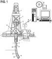
- the disclosed systems and methodsemploy at least one borehole in or near the subsurface region of interest. Such boreholes may be drilled as illustrated in Fig. 1 .
- a drilling platform 2is equipped with a derrick 4 that supports a hoist 6 for raising and lowering a drill string 8.
- the hoist 6suspends a top drive 10 that is used to rotate the drill string 8 and to lower the drill string through the well head 12. Sections of the drill string 8 are connected by threaded connectors 7.
- Connected to the lower end of the drill string 8is a drill bit 14 that rotates to create and extend a borehole 16 along a desired path 18.
- a pump 20circulates drilling fluid through a supply pipe 20 to top drive 10, downhole through the interior of drill string 8, through orifices in drill bit 14, back to the surface via the annulus around drill string 8, and into a retention pit 24.
- the drilling fluidtransports cuttings from the borehole into the pit 24 and aids in maintaining the integrity of the borehole 20.
- Logging instruments 26may be positioned on the drill string 8.
- a telemetry module 28may provide communication between the logging instruments 26 and a surface interface 34 using any one of various available telemetry technologies.
- acoustic sensors 30 and 32detect mud pulse telemetry carrying data from the logging instruments.
- a data processing system 38is coupled to the surface interface 34 by a wired or wireless communications link 36 to control and acquire measurements from the logging instruments 26.
- the illustrated data processing system 38is a general purpose computer with one or more input devices 42 and one or more output devices 44 for interacting with a user.
- Software on information storage media 40(or in the computer's internal memory) configures the computer's internal processor(s) to acquire crosswell tomography measurements and derive a model of the subsurface structure for display to the user.
- Logging instruments 26preferably include acoustic transducers for sending and/or receiving acoustic signals, or electromagnetic antennas for sending and/or receiving electromagnetic ("EM") signals. Though illustrated on a drill string, the logging instruments can additionally be conveyed on a wire line or a coiled tubing string. Data processing system 38 acquires measurements using multiple transmitters and receivers in various positions in and around the region of interest.
- EMelectromagnetic
- Fig. 2Ashows an illustrative configuration in which various transmitters ("T") and receivers ("R”) are positioned in each of the branches of a multilateral well, including a substantially vertical branch penetrating the region of interest and five substantially horizontal branches extending outward in various directions along the top of the reservoir.
- Fig. 2Bshows a different illustrative configuration in which multiple transceiver (transmitter and receiver) nodes are positioned throughout a region of interests using multiple vertical wells, some of which may include lateral branches having additional transceiver nodes.
- Some or all of the boreholesmay be open (i.e., uncased). Similarly, some or all of the boreholes may be cased and the sensors positioned inside the casing. Where the casing causes too much attenuation, the sensors may be configured to send/receive low frequency magnetic waves.
- Some systemsmay employ additional sensors positioned at the surface.
- the number and position of the nodesdepends on the region's volume, properties (resistivity or acoustic impedance), and the desired resolution of the model. Generally, however, a greater number of nodes offers better model accuracy, and a three dimensional arrangement of nodes may be preferred to a two dimensional arrangement, which in turn may be preferred to a one dimensional arrangement. Where some of the nodes are spaced too far from the region of interest to be useful, they may be omitted to avoid introducing unnecessary noise into the inversion process.
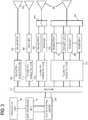
- Fig. 3is a function block diagram of a compensated crosswell tomography system.
- Each of the nodes in Figs. 2A-2Bincludes at least one sensor 302 for transmitting and/or receiving acoustic or EM signals.
- the sensorsare antennas or magnetometers.
- Suitable antenna configurationsinclude a coil antenna (see, e.g., Fig. 4A ) with an optional bucking coil (see, e.g., Fig. 4B ), a toroidal antenna, an electrical gap antenna, a spaced-electrode antenna, and a horn antenna.
- the suitable sensorsinclude piezoelectric transducers, magnetic coil speakers, bender bars, and conventional seismic sources.
- Some of the sensorsare coupled to a transmitter 304 to transmit signals into the formation, some are coupled to a receiver 306 to receive signals from the formation, some are switchable between transmit and receive mode. In the latter case, a switch 308 may be provided between the sensor 302 and its associated transmitter 304 and receiver 306. Some embodiments may even provide multiple transmitters and receivers for at given sensor, e.g., for different signal frequencies. Conversely, the system may include multiple sensors 302 coupled to a given transmitter 304 or receiver 306, e.g., to enable the transmitter or receiver to send or receive signals in different directions or polarizations. Tilted antennas are contemplated for making measurements of orthogonal or linearly independent EM signal components.
- Each nodeincludes a telemetry unit 310 that controls the associated transmitters 304 and receivers 306 (and switches 308) in accordance with commands from a system control center 314.
- a network 312couples the control center 314 to the various nodes via conventional wired or wireless communication links to the well head of each well in the system, and an interface unit at each well head completes the communications chain via an intrawell telemetry channel such as a wireline, an electromagnetic telemetry link, an acoustic telemetry link, or a mud pulse telemetry technique. Any suitable configuration can be used for network 312.
- control center 314iterates through each of the available transmitters 304, causing them to fire in turn while all of the other nodes are set to detect and capture any resulting receive signal.
- the telemetry units 310capture the receiver signals for each transmitter firing and communicate them to the control center 314. Such measurements may be repeated and combined to improve signal to noise ratio.
- the data processing unit 38acquires the set of receiver responses to each transmitter firing and processes them as outlined below to produce a model of the subsurface structure. A user can view and interact with the model via a visualization unit 44.
- Fig. 5shows a high-level block diagram of an inversion process.
- Raw data(the amplitude and phase of each receiver's responses to each transmitter) is processed in block 502 to obtain compensated data.
- an iterative inversion processadapts a structural model of the region of interest until the compensated data are matched by predicted data.
- a forward model block 506generates the predicted data based on the current structural model, and the inversion block responsively adapts the structural model until the error between the predicted and compensated data values falls below a threshold.
- the adapted structural modelis then output by block 504 for visualization and/or analysis to determine the amount and distribution of fluids in the reservoir.
- the compensated datais formed by constructing ratios of the raw data. These ratios are designed to compensate for any systematic errors in the transmit/receive characteristics of the various sensors. Because of this compensation, the results of the inversion process are much improved relative to those of an inversion process performed directly on the raw data. Moreover, this approach relaxes system design constraints, enabling the use of a variety of sensor types, and operation in diverse borehole and environmental circumstances. The synchronization requirements are relaxed, and the system can more easily accommodate miscalibration or parameter drift of the sensors.
- the systemincludes a total of T transmit antennas and a total of R receive antennas, there are a total of T !/(2( T -2)! transmitter pairs and a total of R !/(2( R -2)!) receiver pairs, yielding up to T !R!/(4(T-2)!( R -2)! compensated values.
- the measurementsmay be made at multiple frequencies, further increasing the number of measurements to be matched in the inversion process.
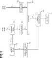
- Fig. 6is a more detailed block diagram of an inversion process.
- the raw datais denoted as v t,r,f where t , r and f in the subscript represent a particular transmitter, receiver and frequency, respectively.
- t , r and fin the subscript represent a particular transmitter, receiver and frequency, respectively.
- p t1,t2,r1,r2,fthe compensated data
- some embodimentsnormalize the raw data with respect to measurements predicted by an assumed (perhaps constant resistivity) background model. Such normalization may be useful for reducing the dominance of strong signal channels in the inversion process.
- a parallel track in Fig. 6begins with an initial model of the subsurface structure in the region of interest, represented in the figure by the conductivity values ⁇ i , j , k 1 , where the superscript indicates an iteration number and i, j, k represent spatial indices in the x, y, and z directions for cells in the conductivity grid.
- the conductivity gridneeds to be chosen large enough to cover the region of interest and other features that might affect the measurements.
- a forward model 604operates on the model to predict the signal measurements for every transmitter-receiver combination and frequency using an initial guess for the formation conductivity.
- the predicted data due to this conductivity profile(denoted as v F t,r,f ) are processed by a block 606 that performs the same operations as block 602.
- the output of block 606is denoted p t 1 , t 2 , r 1 , r 2 F .
- Block 608determines the difference between the outputs of blocks 602 and 608, producing p DIF t1,t2,r1,r2,f .
- Block 610evaluates the magnitude of this difference to determine whether the model has converged.
- convergenceis determined by comparing the magnitude of the difference to the magnitude of compensated data p t1,t2,r1,r2,f , e.g., testing whether ⁇ P DIF ⁇ ⁇ c ⁇ P ⁇ , where P DIF and P are vectors whose elements are producing p DIF t1,t2,r1,r2,f . and p t1,t2,r1,r2,f , respectively and c is a constant. If convergence is satisfied, the block 611 outputs the conductivity model.
- block 612derives a set of changes for the conductivity model based on p DIF
- block 614applies the changes to the conductivity model to arrive at an updated model ⁇ n + 1 i,j,k for iteration step n.
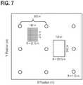
- Fig. 7shows a top view of a simulation model for comparing the performance of the disclosed method to a tomography method that fails to compensate the raw data.
- the simulation modelis a formation bed with nine vertical boreholes each having a transceiver positioned 70 meters above the bottom of the formation bed. The boreholes are evenly spaced apart by 500 meters in X and Y directions.
- the formation bedis assumed to have two resistive anomalies in an otherwise homogeneous medium of 1 ⁇ -m resistivity. Both anomalies have a thickness of 65 m in z-direction. If the middle transceiver is taken as the origin, the first anomaly is the volume defined between 155m and 285 m in x-direction, and -130 to 130 m. in y-direction.
- This anomalyhas a resistivity of 25 ⁇ -m.
- the second anomalyis defined between -290 and -150 m in x-direction and 120 and 330 m in y-direction. Resistivity of this anomaly is taken as 20 ⁇ -m.
- a multi-frequency system with z-directed coil transmitterswas considered with operating frequencies of 1, 2, 5 and 10 Hz.
- Synthetic datawas created with a 3-D finite difference time domain (FDTD) code according to the conductivity profile described above. A 5% multiplicative gain noise was applied to the synthetic data.
- FDTDfinite difference time domain
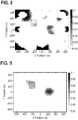
- Fig. 8The results from the traditional inversion of this data are shown in Fig. 8 .
- the true locations of the anomaliesare indicated with dashed lines.
- the inverted imageexhibits severe artifacts due to noise. Although several peaks close to the targets are observed, results also show many false positives and it is not possible to reliably determine the shape and boundaries of the reservoir.
- Fig. 9The results from inversion using compensated values in accordance with the method disclosed above are shown in Fig. 9 .
- the conductivity imageis unaffected by the presence of sensor gain and phase errors. It can be seen that higher intensity regions match very accurately with reservoir boundaries and any false positives occurring due to sensor gain and phase noises are eliminated.
- Fig. 10shows an illustrative flow diagram for compensated crosswell tomography.
- datais obtained from at least two receivers in response to transmissions from at least two transmitters. At least one of the receivers or transmitters are located inside a borehole. The transmitters and receivers can also be distributed among two or more boreholes and on the surface.
- datais obtained from additional pairs of receivers in response to additional pairs of transmitters.
- at least one compensated valueis derived based on the responses of the receivers to the transmitters.
- the compensated valueis expressible as: V ij ⁇ V km ⁇ V im ⁇ V kj ⁇ , where i and k are receiver indices and j and m are transmitter indices.
- An inversionis performed based at least in part on the derived compensated value(s), as shown in block 1008.
- a sub-surface image of a target areais produced based on the inversion.
- the imagecan provide information about at least one formation property, such as acoustic velocity, attenuation, seismic reflectivity, electromagnetic resistivity, or electrical permittivity.
- the operations represented in Fig. 10can be implemented as software on a general purpose computer.
- the processor(s) in such a computerare configured to execute software stored on disk or in memory, the software causing the processors to obtain the data, process it, and display resulting images in accordance with user commands.
- the compensated measurement formulais not the only one that yields cancellation of the gain and phase errors, as combinations of measurements by three receivers in response to three transmitters, or four receivers in response to four transmitters, etc, will yield similar cancellations.
- the following claimsembrace such alternative forms, equivalents, and modifications.
Landscapes
- Life Sciences & Earth Sciences (AREA)
- Physics & Mathematics (AREA)
- General Life Sciences & Earth Sciences (AREA)
- General Physics & Mathematics (AREA)
- Geophysics (AREA)
- Engineering & Computer Science (AREA)
- Environmental & Geological Engineering (AREA)
- Geology (AREA)
- Remote Sensing (AREA)
- Acoustics & Sound (AREA)
- Geophysics And Detection Of Objects (AREA)
- Analysing Materials By The Use Of Radiation (AREA)
Description
- Modern oil field operations demand a great quantity of information relating to the parameters and conditions encountered downhole. Among the types of desired information is the extent and distribution of fluids in the reservoir formations. While it is possible to glean a general picture with surface surveys, such surveys are limited by the effects of the subsurface layers overlying the region of interest. Such effects can be eliminated or reduced by the use of boreholes in or near the region of interest. With a suitable arrangement of borehole transmitters and receivers, crosswell tomography can be used to extract a comparatively detailed image of the region of interest, suitable for planning and monitoring production from a reservoir.
- Initially, crosswell tomography was performed using seismic transmitters and receivers, but more recently the focus has been on the use of electromagnetic (EM) transmitters and receivers. As with any geophysical survey, noise and inaccuracies in the survey system will negatively impact image quality. One important cause of this degradation in crosswell tomography is mismatches between assumed and actual values for sensor gains and phases. These mismatches can result from a number of causes including differences in sensor types, calibration errors, variation in borehole configurations (e.g., mud composition and borehole radius), and environmental parameters such as temperature and pressure. Phase mismatches can be caused or exacerbated by latencies in electronic systems and synchronization errors for the widely-distributed components of a typical crosswell tomography system. Traditional methods crosswell tomography do not appear to adequately address such inaccuracies.
- Documents cited during prosecution include
US 2002/0000808 A1 , which discloses a permanently emplaced electromagnetic system and method measuring formation resistivity adjacent to and between wells;US 2009/0005992 A1 , which discloses a method and system for removing effects of conductive casings and wellbore and surface heterogeneity in electromagnetic imaging surveys;US 2003/023381 A1 ; andWO 2012/064342 A1 , which discloses a system and method of making environmental measurements. - According to a first aspect of the present invention, there is a provided a method for improving image quality of crosswell tomography, comprising: obtaining data from at least two receivers in response to transmissions from at least two transmitters, wherein the transmitters and receivers are distributed among two or more boreholes; deriving at least one compensated value that combines the data from the at least two receivers' responses to the at least two transmitters as a ratio that cancels errors between actual and assumed characteristics of the at least two receivers and the at least two transmitters; and performing an inversion based at least in part on said compensated value to obtain a sub surface image, wherein said compensated value compensates for inaccuracies including sensor gains and phase variations, wherein said compensated value is expressible by

- According to a second aspect of the present invention, there is a provided a system for improving image quality of crosswell tomography, comprising: a memory unit that stores inversion software; and a processor coupled to said memory to execute the software, wherein said software configures said processor to: obtain data from at least two receivers in response to transmissions from at least two transmitters, wherein one of said receivers or transmitters are in a borehole; derive at least one compensated value based on responses of said receivers to each of said transmitters that are combined as a ratio that cancels errors between actual and assumed characteristics of said receivers and said transmitters; and perform an inversion based at least in part on said compensated value to obtain a subsurface image, wherein said compensated value compensates for inaccuracies including sensor gains and phase variations, wherein said compensated value is expressible by

- For a better understanding of the present invention, reference will be made, by way of example only, to the following drawings, in which:
Fig. 1 shows an illustrative drilling environment;Fig. 2A shows an illustrative multilateral environment for crosswell tomography;Fig. 2B shows an illustrative multiple borehole environment for crosswell tomography;Fig. 3 is a function block diagram of an illustrative compensated crosswell tomography system;Figs. 4A and 4B shows illustrative configurations for electromagnetic (EM) transmit and receive antennas;Fig. 5 is a high-level flow diagram of an illustrative inversion process;Fig. 6 is a detailed flow diagram of an illustrative inversion process;Fig. 7 shows an illustrative reservoir model for simulation;Fig. 8 shows traditional inversion results for the illustrative simulation;Fig. 9 shows compensated inversion results for the illustrative simulation; andFig. 10 is a flow diagram of an illustrative compensated crosswell tomography method.- While the invention is susceptible to various alternative forms, equivalents, and modifications, specific embodiments thereof are shown by way of example in the drawings and will herein be described in detail. It should be understood, however, that the drawings and detailed description thereto do not limit the disclosure, but on the contrary, they provide the foundation for one of ordinary skill to discern the alternative forms, equivalents, and modifications that are encompassed with the described embodiments by the scope of the appended claims.
- The issues identified in the background are at least in part addressed by the disclosed compensated crosswell tomography methods and systems. In at least some method embodiments, data is obtained from at least two receivers in response to each of at least two transmitters, the transmitters and receivers being located in boreholes near the region of interest. The data is combined to form at least one compensated value that compensates for any transmitter and receiver gain or phase inaccuracies. An inversion is then performed to identify the subsurface structure that best matches these compensated values. At least some system embodiments implement this method using software that then outputs one or more images derived from the subsurface structure.
- The disclosed systems and methods employ at least one borehole in or near the subsurface region of interest. Such boreholes may be drilled as illustrated in
Fig. 1 . Adrilling platform 2 is equipped with aderrick 4 that supports a hoist 6 for raising and lowering adrill string 8. The hoist 6 suspends atop drive 10 that is used to rotate thedrill string 8 and to lower the drill string through thewell head 12. Sections of thedrill string 8 are connected by threadedconnectors 7. Connected to the lower end of thedrill string 8 is adrill bit 14 that rotates to create and extend aborehole 16 along a desired path 18. Apump 20 circulates drilling fluid through asupply pipe 20 totop drive 10, downhole through the interior ofdrill string 8, through orifices indrill bit 14, back to the surface via the annulus arounddrill string 8, and into aretention pit 24. The drilling fluid transports cuttings from the borehole into thepit 24 and aids in maintaining the integrity of theborehole 20. - Logging
instruments 26 may be positioned on thedrill string 8. Atelemetry module 28 may provide communication between thelogging instruments 26 and asurface interface 34 using any one of various available telemetry technologies. In one example,acoustic sensors data processing system 38 is coupled to thesurface interface 34 by a wired orwireless communications link 36 to control and acquire measurements from thelogging instruments 26. The illustrateddata processing system 38 is a general purpose computer with one ormore input devices 42 and one ormore output devices 44 for interacting with a user. Software on information storage media 40 (or in the computer's internal memory) configures the computer's internal processor(s) to acquire crosswell tomography measurements and derive a model of the subsurface structure for display to the user. Logging instruments 26 preferably include acoustic transducers for sending and/or receiving acoustic signals, or electromagnetic antennas for sending and/or receiving electromagnetic ("EM") signals. Though illustrated on a drill string, the logging instruments can additionally be conveyed on a wire line or a coiled tubing string.Data processing system 38 acquires measurements using multiple transmitters and receivers in various positions in and around the region of interest.Fig. 2A shows an illustrative configuration in which various transmitters ("T") and receivers ("R") are positioned in each of the branches of a multilateral well, including a substantially vertical branch penetrating the region of interest and five substantially horizontal branches extending outward in various directions along the top of the reservoir.Fig. 2B shows a different illustrative configuration in which multiple transceiver (transmitter and receiver) nodes are positioned throughout a region of interests using multiple vertical wells, some of which may include lateral branches having additional transceiver nodes. Some or all of the boreholes may be open (i.e., uncased). Similarly, some or all of the boreholes may be cased and the sensors positioned inside the casing. Where the casing causes too much attenuation, the sensors may be configured to send/receive low frequency magnetic waves. Some systems may employ additional sensors positioned at the surface.- The number and position of the nodes depends on the region's volume, properties (resistivity or acoustic impedance), and the desired resolution of the model. Generally, however, a greater number of nodes offers better model accuracy, and a three dimensional arrangement of nodes may be preferred to a two dimensional arrangement, which in turn may be preferred to a one dimensional arrangement. Where some of the nodes are spaced too far from the region of interest to be useful, they may be omitted to avoid introducing unnecessary noise into the inversion process.
Fig. 3 is a function block diagram of a compensated crosswell tomography system. Each of the nodes inFigs. 2A-2B includes at least onesensor 302 for transmitting and/or receiving acoustic or EM signals. For an EM system the sensors are antennas or magnetometers. Suitable antenna configurations include a coil antenna (see, e.g.,Fig. 4A ) with an optional bucking coil (see, e.g.,Fig. 4B ), a toroidal antenna, an electrical gap antenna, a spaced-electrode antenna, and a horn antenna. For an acoustic system, the suitable sensors include piezoelectric transducers, magnetic coil speakers, bender bars, and conventional seismic sources.- Some of the sensors are coupled to a
transmitter 304 to transmit signals into the formation, some are coupled to areceiver 306 to receive signals from the formation, some are switchable between transmit and receive mode. In the latter case, aswitch 308 may be provided between thesensor 302 and its associatedtransmitter 304 andreceiver 306. Some embodiments may even provide multiple transmitters and receivers for at given sensor, e.g., for different signal frequencies. Conversely, the system may includemultiple sensors 302 coupled to a giventransmitter 304 orreceiver 306, e.g., to enable the transmitter or receiver to send or receive signals in different directions or polarizations. Tilted antennas are contemplated for making measurements of orthogonal or linearly independent EM signal components. - Each node includes a
telemetry unit 310 that controls the associatedtransmitters 304 and receivers 306 (and switches 308) in accordance with commands from asystem control center 314. Anetwork 312 couples thecontrol center 314 to the various nodes via conventional wired or wireless communication links to the well head of each well in the system, and an interface unit at each well head completes the communications chain via an intrawell telemetry channel such as a wireline, an electromagnetic telemetry link, an acoustic telemetry link, or a mud pulse telemetry technique. Any suitable configuration can be used fornetwork 312. - During normal operation, the
control center 314 iterates through each of theavailable transmitters 304, causing them to fire in turn while all of the other nodes are set to detect and capture any resulting receive signal. Thetelemetry units 310 capture the receiver signals for each transmitter firing and communicate them to thecontrol center 314. Such measurements may be repeated and combined to improve signal to noise ratio. Thedata processing unit 38 acquires the set of receiver responses to each transmitter firing and processes them as outlined below to produce a model of the subsurface structure. A user can view and interact with the model via avisualization unit 44. Fig. 5 shows a high-level block diagram of an inversion process. Raw data (the amplitude and phase of each receiver's responses to each transmitter) is processed inblock 502 to obtain compensated data. Inblock 504, an iterative inversion process adapts a structural model of the region of interest until the compensated data are matched by predicted data. Aforward model block 506 generates the predicted data based on the current structural model, and the inversion block responsively adapts the structural model until the error between the predicted and compensated data values falls below a threshold. The adapted structural model is then output byblock 504 for visualization and/or analysis to determine the amount and distribution of fluids in the reservoir.- The compensated data is formed by constructing ratios of the raw data. These ratios are designed to compensate for any systematic errors in the transmit/receive characteristics of the various sensors. Because of this compensation, the results of the inversion process are much improved relative to those of an inversion process performed directly on the raw data. Moreover, this approach relaxes system design constraints, enabling the use of a variety of sensor types, and operation in diverse borehole and environmental circumstances. The synchronization requirements are relaxed, and the system can more easily accommodate miscalibration or parameter drift of the sensors.
- Let


Fig. 6 is a more detailed block diagram of an inversion process. The raw data is denoted as vt,r,f where t , r and f in the subscript represent a particular transmitter, receiver and frequency, respectively. Once raw data is obtained, it is passed through an initial processing stage to obtain the compensated data pt1,t2,r1,r2,f. Note that prior to determining the compensated values, some embodiments normalize the raw data with respect to measurements predicted by an assumed (perhaps constant resistivity) background model. Such normalization may be useful for reducing the dominance of strong signal channels in the inversion process.- A parallel track in
Fig. 6 begins with an initial model of the subsurface structure in the region of interest, represented in the figure by the conductivity values
forward model 604 operates on the model to predict the signal measurements for every transmitter-receiver combination and frequency using an initial guess for the formation conductivity. The predicted data due to this conductivity profile (denoted asvFt,r,f) are processed by ablock 606 that performs the same operations asblock 602. The output ofblock 606 is denoted
Block 608 determines the difference between the outputs ofblocks Block 610 evaluates the magnitude of this difference to determine whether the model has converged. In some embodiments, convergence is determined by comparing the magnitude of the difference to the magnitude of compensated data pt1,t2,r1,r2,f, e.g., testing whether ∥P DIF∥ ≤c∥P∥, whereP DIF andP are vectors whose elements are producingpDIFt1,t2,r1,r2,f. andpt1,t2,r1,r2,f, respectively and c is a constant. If convergence is satisfied, theblock 611 outputs the conductivity model. Otherwise, block 612 derives a set of changes for the conductivity model based onpDIF, and block 614 applies the changes to the conductivity model to arrive at an updated modelσn+1i,j,k for iteration stepn. Fig. 7 shows a top view of a simulation model for comparing the performance of the disclosed method to a tomography method that fails to compensate the raw data. The simulation model is a formation bed with nine vertical boreholes each having a transceiver positioned 70 meters above the bottom of the formation bed. The boreholes are evenly spaced apart by 500 meters in X and Y directions. The formation bed is assumed to have two resistive anomalies in an otherwise homogeneous medium of 1 Ω-m resistivity. Both anomalies have a thickness of 65 m in z-direction. If the middle transceiver is taken as the origin, the first anomaly is the volume defined between 155m and 285 m in x-direction, and -130 to 130 m. in y-direction. This anomaly has a resistivity of 25 Ω-m. The second anomaly is defined between -290 and -150 m in x-direction and 120 and 330 m in y-direction. Resistivity of this anomaly is taken as 20 Ω-m. A multi-frequency system with z-directed coil transmitters was considered with operating frequencies of 1, 2, 5 and 10 Hz. Synthetic data was created with a 3-D finite difference time domain (FDTD) code according to the conductivity profile described above. A 5% multiplicative gain noise was applied to the synthetic data.- The results from the traditional inversion of this data are shown in
Fig. 8 . The true locations of the anomalies are indicated with dashed lines. The inverted image exhibits severe artifacts due to noise. Although several peaks close to the targets are observed, results also show many false positives and it is not possible to reliably determine the shape and boundaries of the reservoir. - The results from inversion using compensated values in accordance with the method disclosed above are shown in
Fig. 9 . The conductivity image is unaffected by the presence of sensor gain and phase errors. It can be seen that higher intensity regions match very accurately with reservoir boundaries and any false positives occurring due to sensor gain and phase noises are eliminated. Fig. 10 shows an illustrative flow diagram for compensated crosswell tomography. Inblock 1002, data is obtained from at least two receivers in response to transmissions from at least two transmitters. At least one of the receivers or transmitters are located inside a borehole. The transmitters and receivers can also be distributed among two or more boreholes and on the surface. Inblock 1004, data is obtained from additional pairs of receivers in response to additional pairs of transmitters. Inblock 1006, at least one compensated value is derived based on the responses of the receivers to the transmitters. The compensated value is expressible as:
block 1008. Finally, inblock 1010, a sub-surface image of a target area is produced based on the inversion. The image can provide information about at least one formation property, such as acoustic velocity, attenuation, seismic reflectivity, electromagnetic resistivity, or electrical permittivity.- The operations represented in
Fig. 10 can be implemented as software on a general purpose computer. The processor(s) in such a computer are configured to execute software stored on disk or in memory, the software causing the processors to obtain the data, process it, and display resulting images in accordance with user commands. - One of ordinary skill, upon reviewing the foregoing disclosure, will recognize various alternative forms, equivalents, and modifications to disclosed elements and operations. For example, the compensated measurement formula is not the only one that yields cancellation of the gain and phase errors, as combinations of measurements by three receivers in response to three transmitters, or four receivers in response to four transmitters, etc, will yield similar cancellations. Where possible, the following claims embrace such alternative forms, equivalents, and modifications.


Claims (11)
- A computer implemented method for improving image quality of crosswell tomography, comprising:obtaining data from at least two receivers (306) in response to transmissions from at least two transmitters (304), wherein the transmitters (304) and receivers (306) are distributed among two or more boreholes;deriving at least one compensated value (Pikjm) that combines the data from the at least two receivers' (306) responses to the at least two transmitters (304) as a ratio that cancels errors between actual and assumed characteristics of the at least two receivers (306) and the at least two transmitters (304); andperforming an inversion based at least in part on said compensated value to obtain a sub surface image, wherein said compensated value (Pikjm) compensates for inaccuracies including sensor gains and phase variations, wherein said compensated value (Pikjm) is expressible by

- The method of any preceding claim, wherein said obtaining data further includes obtaining data from additional receivers (306) in response to additional pairs of transmitters (304).
- The method of any preceding claim, wherein said data is expressible as a complex value to represent gain and phase.
- The method of any preceding claim, wherein the receivers (306) include at least one of: a magnetic dipole, an electric dipole, spaced-apart electrodes.
- The method of any preceding claim, wherein said image provides information about at least one formation property selected from a set of consisting of: acoustic velocity, attenuation, seismic reflectivity, and electromagnetic resistivity.
- A system for improving image quality of crosswell tomography, comprising:a memory unit (40) that stores inversion software; anda processor coupled to said memory (40) to execute the software, wherein said software configures said processor to:obtain data from at least two receivers (306) in response to transmissions from at least two transmitters (304), wherein one of said receivers (306) or transmitters (304) are in a borehole;derive at least one compensated value (Pikjm) based on responses of said receivers (306) to each of said transmitters (304) that are combined as a ratio that cancels errors between actual and assumed characteristics of said receivers (306) and said transmitters (304); andperform an inversion based at least in part on said compensated value (Pikjm) to obtain a subsurface image, wherein said compensated value compensates for inaccuracies including sensor gains and phase variations, wherein said compensated value is expressible by

- The system of Claim 6, further comprising a network electrically coupled to said processor, at least two transmitters (304), and at least two receivers (306), wherein at least one of said transmitters or one of said receivers is located inside said borehole, and, optionally, wherein said network is electrically coupled to at least one sensor, at least one transmitter, and at least one receiver.
- The system of Claim 6 or 7, wherein said software further configures the processor to obtain data from additional receivers in response to additional pairs of transmitters.
- The system of any one of Claims 6 to 8, wherein said data is expressible as a complex value to represent gain and phase.
- The system of any one of Claims 6 to 9, wherein said image provides information about at least one formation property selected from a set of consisting of: acoustic velocity, attenuation, seismic reflectivity, and electromagnetic resistivity.
- The system of any one of Claims 6 to 10, wherein the transmitters and receivers are each coupled to an antenna, the antenna being in the set consisting of coils, solenoids, wire antennas, electrodes, gap antennas, and toroids.


Applications Claiming Priority (1)
| Application Number | Priority Date | Filing Date | Title |
|---|---|---|---|
| PCT/US2011/055020WO2013052049A1 (en) | 2011-10-06 | 2011-10-06 | Compensated cross-well tomography methods and systems |
Publications (3)
| Publication Number | Publication Date |
|---|---|
| EP2742365A1 EP2742365A1 (en) | 2014-06-18 |
| EP2742365A4 EP2742365A4 (en) | 2015-01-14 |
| EP2742365B1true EP2742365B1 (en) | 2017-03-01 |
Family
ID=48044027
Family Applications (1)
| Application Number | Title | Priority Date | Filing Date |
|---|---|---|---|
| EP11873738.6ANot-in-forceEP2742365B1 (en) | 2011-10-06 | 2011-10-06 | Compensated cross-well tomography methods and systems |
Country Status (9)
| Country | Link |
|---|---|
| US (1) | US9008970B2 (en) |
| EP (1) | EP2742365B1 (en) |
| CN (1) | CN103842852B (en) |
| AU (1) | AU2011378454B2 (en) |
| BR (1) | BR112014005881A2 (en) |
| CA (1) | CA2845627C (en) |
| IN (1) | IN2014DN01793A (en) |
| RU (1) | RU2577418C2 (en) |
| WO (1) | WO2013052049A1 (en) |
Families Citing this family (22)
| Publication number | Priority date | Publication date | Assignee | Title |
|---|---|---|---|---|
| US9008970B2 (en) | 2011-10-06 | 2015-04-14 | Halliburton Energy Services, Inc. | Compensated crosswell tomography methods and systems |
| US20150378046A1 (en)* | 2013-10-03 | 2015-12-31 | Halliburton Energy Services, Inc. | Downhole tool with radial array of conformable sensors for downhole detection and imaging |
| WO2015088563A1 (en) | 2013-12-13 | 2015-06-18 | Halliburton Energy Services, Inc. | Methods and systems of electromagnetic interferometry for downhole environments |
| AU2015253515B2 (en) | 2014-05-01 | 2017-06-15 | Halliburton Energy Services, Inc. | Multilateral production control methods and systems employing a casing segment with at least one transmission crossover arrangement |
| MY177192A (en) | 2014-05-01 | 2020-09-09 | Halliburton Energy Services Inc | Casing segment having at least one transmission crossover arrangement |
| CA2947008C (en) | 2014-05-01 | 2020-06-30 | Halliburton Energy Services, Inc. | Guided drilling methods and systems employing a casing segment with at least one transmission crossover arrangement |
| CN106460506B (en)* | 2014-05-01 | 2022-06-10 | 哈利伯顿能源服务公司 | Interwell tomography method and system employing casing segments with at least one transmission crossover arrangement |
| CN104391333B (en)* | 2014-10-21 | 2017-04-26 | 安徽理工大学 | Multi-inter well geological information detecting and processing system and method |
| WO2016085511A1 (en) | 2014-11-26 | 2016-06-02 | Halliburton Energy Services, Inc. | Onshore electromagnetic reservoir monitoring |
| CN104360396B (en)* | 2014-12-04 | 2016-10-19 | 中国海洋石油总公司 | A kind of three kinds of preliminary wave Zoumaling tunnel methods of TTI medium between offshore well |
| EP3384324A4 (en)* | 2015-12-03 | 2018-12-19 | Halliburton Energy Services, Inc. | Crosswell tomography using an array of optical fiber transducers |
| EP3469185B1 (en) | 2016-08-12 | 2023-05-10 | Halliburton Energy Services, Inc. | Multistage processing and inversion of corrosion detection tools |
| BR112019014495A2 (en)* | 2017-02-06 | 2020-02-11 | Halliburton Energy Services, Inc. | METHOD AND SYSTEM FOR MODELING UNDERGROUND TRAINING, AND, LEGIBLE MEANS BY NON-TRANSITIONAL COMPUTER. |
| US11723579B2 (en) | 2017-09-19 | 2023-08-15 | Neuroenhancement Lab, LLC | Method and apparatus for neuroenhancement |
| US11717686B2 (en) | 2017-12-04 | 2023-08-08 | Neuroenhancement Lab, LLC | Method and apparatus for neuroenhancement to facilitate learning and performance |
| US11273283B2 (en) | 2017-12-31 | 2022-03-15 | Neuroenhancement Lab, LLC | Method and apparatus for neuroenhancement to enhance emotional response |
| US12280219B2 (en) | 2017-12-31 | 2025-04-22 | NeuroLight, Inc. | Method and apparatus for neuroenhancement to enhance emotional response |
| US11364361B2 (en) | 2018-04-20 | 2022-06-21 | Neuroenhancement Lab, LLC | System and method for inducing sleep by transplanting mental states |
| EP3849410A4 (en) | 2018-09-14 | 2022-11-02 | Neuroenhancement Lab, LLC | SLEEP ENHANCEMENT SYSTEM AND METHOD |
| RU2706205C1 (en)* | 2019-04-30 | 2019-11-14 | Общество С Ограниченной Ответственностью "Радионда" | Radio-wave geointroscopy system of inter-well space |
| US11817799B2 (en)* | 2020-11-20 | 2023-11-14 | Halliburton Energy Services, Inc. | Single crystal ultrasonic transducer with charge mode receiver |
| US12416622B2 (en) | 2022-12-15 | 2025-09-16 | Halliburton Energy Services, Inc. | Sensors for measuring properties of materials flowing through a flowline |
Citations (1)
| Publication number | Priority date | Publication date | Assignee | Title |
|---|---|---|---|---|
| EP2628027A1 (en)* | 2010-11-12 | 2013-08-21 | Halliburton Energy Services, Inc. | System and method of making environmental measurements |
Family Cites Families (21)
| Publication number | Priority date | Publication date | Assignee | Title |
|---|---|---|---|---|
| US4446434A (en) | 1978-12-20 | 1984-05-01 | Conoco Inc. | Hydrocarbon prospecting method with changing of electrode spacing for the indirect detection of hydrocarbon reservoirs |
| US5355088A (en)* | 1991-04-16 | 1994-10-11 | Schlumberger Technology Corporation | Method and apparatus for determining parameters of a transition zone of a formation traversed by a wellbore and generating a more accurate output record medium |
| US6179084B1 (en) | 1997-03-17 | 2001-01-30 | Yamamoto Engineering Corporation | Underground acoustic wave transmitter, receiver, transmitting/receiving method, and underground exploration using this |
| US6703838B2 (en) | 1998-04-13 | 2004-03-09 | Schlumberger Technology Corporation | Method and apparatus for measuring characteristics of geological formations |
| US6534986B2 (en)* | 2000-05-01 | 2003-03-18 | Schlumberger Technology Corporation | Permanently emplaced electromagnetic system and method for measuring formation resistivity adjacent to and between wells |
| US6393363B1 (en)* | 2000-06-28 | 2002-05-21 | Schlumberger Technology Corporation | Method and apparatus for the measurement of the electrical resistivity of geologic formations employing modeling data |
| US6538447B2 (en) | 2000-12-13 | 2003-03-25 | Halliburton Energy Services, Inc. | Compensated multi-mode elctromagnetic wave resistivity tool |
| US8296113B2 (en) | 2001-05-18 | 2012-10-23 | Halliburton Energy Services, Inc. | Virtual steering of induction tool attenuation and phase difference measurements |
| US6777940B2 (en)* | 2002-11-08 | 2004-08-17 | Ultima Labs, Inc. | Apparatus and method for resistivity well logging |
| US7046581B2 (en) | 2003-12-01 | 2006-05-16 | Shell Oil Company | Well-to-well tomography |
| CA2627861C (en) | 2005-11-01 | 2012-04-17 | Exxonmobil Upstream Research Company | Method for phase and amplitude correction in controlled source electromagnetic survey data |
| KR100861084B1 (en)* | 2006-12-08 | 2008-09-30 | 한국지질자원연구원 | 4D inversion method of physical exploration data and 4D imaging method of underground structure using the same. |
| US8131526B2 (en)* | 2007-04-14 | 2012-03-06 | Schlumberger Technology Corporation | System and method for evaluating petroleum reservoir using forward modeling |
| US7565244B2 (en)* | 2007-06-27 | 2009-07-21 | Schlumberger Technology Corporation | Method and system for removing effects of conductive casings and wellbore and surface heterogeneity in electromagnetic imaging surveys |
| US8129993B2 (en)* | 2007-07-10 | 2012-03-06 | Schlumberger Technology Corporation | Determining formation parameters using electromagnetic coupling components |
| US7852087B2 (en)* | 2007-08-10 | 2010-12-14 | Schlumberger Technology Corporation | Removing effects of near surface geology from surface-to-borehole electromagnetic data |
| US8401796B2 (en) | 2008-09-29 | 2013-03-19 | Schlumberger Technology Corporation | Methods and systems for acoustically monitoring formations |
| US8456166B2 (en)* | 2008-12-02 | 2013-06-04 | Schlumberger Technology Corporation | Single-well through casing induction logging tool |
| US8812237B2 (en) | 2009-02-05 | 2014-08-19 | Schlumberger Technology Corporation | Deep-reading electromagnetic data acquisition method |
| US9612355B2 (en) | 2010-07-09 | 2017-04-04 | Halliburton Energy Services, Inc. | Imaging and sensing of subterranean reservoirs |
| US9008970B2 (en) | 2011-10-06 | 2015-04-14 | Halliburton Energy Services, Inc. | Compensated crosswell tomography methods and systems |
- 2011
- 2011-10-06USUS14/349,872patent/US9008970B2/enactiveActive
- 2011-10-06AUAU2011378454Apatent/AU2011378454B2/ennot_activeCeased
- 2011-10-06CNCN201180073478.1Apatent/CN103842852B/ennot_activeExpired - Fee Related
- 2011-10-06EPEP11873738.6Apatent/EP2742365B1/ennot_activeNot-in-force
- 2011-10-06RURU2014113422/28Apatent/RU2577418C2/ennot_activeIP Right Cessation
- 2011-10-06ININ1793DEN2014patent/IN2014DN01793A/enunknown
- 2011-10-06BRBR112014005881Apatent/BR112014005881A2/ennot_activeApplication Discontinuation
- 2011-10-06WOPCT/US2011/055020patent/WO2013052049A1/enactiveApplication Filing
- 2011-10-06CACA2845627Apatent/CA2845627C/ennot_activeExpired - Fee Related
Patent Citations (1)
| Publication number | Priority date | Publication date | Assignee | Title |
|---|---|---|---|---|
| EP2628027A1 (en)* | 2010-11-12 | 2013-08-21 | Halliburton Energy Services, Inc. | System and method of making environmental measurements |
Also Published As
| Publication number | Publication date |
|---|---|
| CN103842852A (en) | 2014-06-04 |
| US20140244175A1 (en) | 2014-08-28 |
| AU2011378454A1 (en) | 2014-03-06 |
| CA2845627C (en) | 2016-11-29 |
| AU2011378454B2 (en) | 2015-05-21 |
| CN103842852B (en) | 2017-11-10 |
| BR112014005881A2 (en) | 2017-03-28 |
| EP2742365A4 (en) | 2015-01-14 |
| RU2577418C2 (en) | 2016-03-20 |
| EP2742365A1 (en) | 2014-06-18 |
| IN2014DN01793A (en) | 2015-05-15 |
| CA2845627A1 (en) | 2013-04-11 |
| US9008970B2 (en) | 2015-04-14 |
| RU2014113422A (en) | 2015-11-20 |
| WO2013052049A1 (en) | 2013-04-11 |
Similar Documents
| Publication | Publication Date | Title |
|---|---|---|
| EP2742365B1 (en) | Compensated cross-well tomography methods and systems | |
| US10627541B2 (en) | System, method and computer-program product for in-situ calibration of a wellbore resistivity logging tool | |
| AU2003278866B2 (en) | Fixed-depth of investigation log for multi-spacing multi-frequency LWD resistivity tools | |
| US10451765B2 (en) | Post-well reservoir characterization using image-constrained inversion | |
| NO348938B1 (en) | Measuring petrophysical properties of an earth formation by regularized direct inversion of electromagnetic signals | |
| US10359535B2 (en) | Electrode-based tool measurement corrections based on measured leakage currents | |
| AU2017263252B2 (en) | Methods and systems employing look-around and look-ahead inversion of downhole measurements | |
| US10031254B2 (en) | Electrode-based tool measurement corrections based on leakage currents estimated using a predetermined internal impedance model or table | |
| US10914859B2 (en) | Real-time true resistivity estimation for logging-while-drilling tools | |
| CN103590823B (en) | Measure the device of formation resistivity at drill place | |
| NO20160142A1 (en) | Surface calibration of a wellbore resistivity logging tool | |
| US20170038495A1 (en) | Systems and methods for relative dip correction | |
| US10302802B2 (en) | Apparatus and methods of skin effect correction | |
| WO2017078740A1 (en) | Downhole logging systems and methods employing adjustably-spaced modules | |
| US10459110B2 (en) | Flexible conductive shield for downhole electromagnetic noise suppression | |
| NO348153B1 (en) | Identifying antenna system parameter changes | |
| AU2016433067A1 (en) | Use of gap subs behind a coil antenna in electromagnetic induction tools |
Legal Events
| Date | Code | Title | Description |
|---|---|---|---|
| PUAI | Public reference made under article 153(3) epc to a published international application that has entered the european phase | Free format text:ORIGINAL CODE: 0009012 | |
| 17P | Request for examination filed | Effective date:20140313 | |
| AK | Designated contracting states | Kind code of ref document:A1 Designated state(s):AL AT BE BG CH CY CZ DE DK EE ES FI FR GB GR HR HU IE IS IT LI LT LU LV MC MK MT NL NO PL PT RO RS SE SI SK SM TR | |
| RIN1 | Information on inventor provided before grant (corrected) | Inventor name:SAN MARTIN, LUIS, E. Inventor name:BITTAR, MICHAEL, S. Inventor name:GUNER, BARIS Inventor name:DONDERICI, BURKAY | |
| A4 | Supplementary search report drawn up and despatched | Effective date:20141215 | |
| DAX | Request for extension of the european patent (deleted) | ||
| RIC1 | Information provided on ipc code assigned before grant | Ipc:G01V 1/42 20060101ALN20141209BHEP Ipc:G01V 3/18 20060101AFI20141209BHEP | |
| 17Q | First examination report despatched | Effective date:20160205 | |
| REG | Reference to a national code | Ref country code:DE Ref legal event code:R079 Ref document number:602011035585 Country of ref document:DE Free format text:PREVIOUS MAIN CLASS: G01V0001000000 Ipc:G01V0003180000 | |
| RIC1 | Information provided on ipc code assigned before grant | Ipc:G01V 1/42 20060101ALN20160810BHEP Ipc:G01V 3/18 20060101AFI20160810BHEP | |
| GRAP | Despatch of communication of intention to grant a patent | Free format text:ORIGINAL CODE: EPIDOSNIGR1 | |
| RIC1 | Information provided on ipc code assigned before grant | Ipc:G01V 1/42 20060101ALN20160907BHEP Ipc:G01V 3/18 20060101AFI20160907BHEP | |
| RIC1 | Information provided on ipc code assigned before grant | Ipc:G01V 3/18 20060101AFI20160912BHEP Ipc:G01V 1/42 20060101ALN20160912BHEP | |
| INTG | Intention to grant announced | Effective date:20160928 | |
| GRAS | Grant fee paid | Free format text:ORIGINAL CODE: EPIDOSNIGR3 | |
| GRAA | (expected) grant | Free format text:ORIGINAL CODE: 0009210 | |
| AK | Designated contracting states | Kind code of ref document:B1 Designated state(s):AL AT BE BG CH CY CZ DE DK EE ES FI FR GB GR HR HU IE IS IT LI LT LU LV MC MK MT NL NO PL PT RO RS SE SI SK SM TR | |
| REG | Reference to a national code | Ref country code:GB Ref legal event code:FG4D | |
| REG | Reference to a national code | Ref country code:CH Ref legal event code:EP Ref country code:AT Ref legal event code:REF Ref document number:872001 Country of ref document:AT Kind code of ref document:T Effective date:20170315 | |
| REG | Reference to a national code | Ref country code:IE Ref legal event code:FG4D | |
| REG | Reference to a national code | Ref country code:DE Ref legal event code:R096 Ref document number:602011035585 Country of ref document:DE | |
| REG | Reference to a national code | Ref country code:NO Ref legal event code:T2 Effective date:20170301 | |
| REG | Reference to a national code | Ref country code:NL Ref legal event code:MP Effective date:20170301 | |
| REG | Reference to a national code | Ref country code:LT Ref legal event code:MG4D | |
| REG | Reference to a national code | Ref country code:AT Ref legal event code:MK05 Ref document number:872001 Country of ref document:AT Kind code of ref document:T Effective date:20170301 | |
| PG25 | Lapsed in a contracting state [announced via postgrant information from national office to epo] | Ref country code:GR Free format text:LAPSE BECAUSE OF FAILURE TO SUBMIT A TRANSLATION OF THE DESCRIPTION OR TO PAY THE FEE WITHIN THE PRESCRIBED TIME-LIMIT Effective date:20170602 Ref country code:HR Free format text:LAPSE BECAUSE OF FAILURE TO SUBMIT A TRANSLATION OF THE DESCRIPTION OR TO PAY THE FEE WITHIN THE PRESCRIBED TIME-LIMIT Effective date:20170301 Ref country code:FI Free format text:LAPSE BECAUSE OF FAILURE TO SUBMIT A TRANSLATION OF THE DESCRIPTION OR TO PAY THE FEE WITHIN THE PRESCRIBED TIME-LIMIT Effective date:20170301 Ref country code:LT Free format text:LAPSE BECAUSE OF FAILURE TO SUBMIT A TRANSLATION OF THE DESCRIPTION OR TO PAY THE FEE WITHIN THE PRESCRIBED TIME-LIMIT Effective date:20170301 | |
| PG25 | Lapsed in a contracting state [announced via postgrant information from national office to epo] | Ref country code:BG Free format text:LAPSE BECAUSE OF FAILURE TO SUBMIT A TRANSLATION OF THE DESCRIPTION OR TO PAY THE FEE WITHIN THE PRESCRIBED TIME-LIMIT Effective date:20170601 Ref country code:RS Free format text:LAPSE BECAUSE OF FAILURE TO SUBMIT A TRANSLATION OF THE DESCRIPTION OR TO PAY THE FEE WITHIN THE PRESCRIBED TIME-LIMIT Effective date:20170301 Ref country code:ES Free format text:LAPSE BECAUSE OF FAILURE TO SUBMIT A TRANSLATION OF THE DESCRIPTION OR TO PAY THE FEE WITHIN THE PRESCRIBED TIME-LIMIT Effective date:20170301 Ref country code:SE Free format text:LAPSE BECAUSE OF FAILURE TO SUBMIT A TRANSLATION OF THE DESCRIPTION OR TO PAY THE FEE WITHIN THE PRESCRIBED TIME-LIMIT Effective date:20170301 Ref country code:LV Free format text:LAPSE BECAUSE OF FAILURE TO SUBMIT A TRANSLATION OF THE DESCRIPTION OR TO PAY THE FEE WITHIN THE PRESCRIBED TIME-LIMIT Effective date:20170301 Ref country code:AT Free format text:LAPSE BECAUSE OF FAILURE TO SUBMIT A TRANSLATION OF THE DESCRIPTION OR TO PAY THE FEE WITHIN THE PRESCRIBED TIME-LIMIT Effective date:20170301 | |
| PG25 | Lapsed in a contracting state [announced via postgrant information from national office to epo] | Ref country code:NL Free format text:LAPSE BECAUSE OF FAILURE TO SUBMIT A TRANSLATION OF THE DESCRIPTION OR TO PAY THE FEE WITHIN THE PRESCRIBED TIME-LIMIT Effective date:20170301 | |
| PG25 | Lapsed in a contracting state [announced via postgrant information from national office to epo] | Ref country code:IT Free format text:LAPSE BECAUSE OF FAILURE TO SUBMIT A TRANSLATION OF THE DESCRIPTION OR TO PAY THE FEE WITHIN THE PRESCRIBED TIME-LIMIT Effective date:20170301 Ref country code:RO Free format text:LAPSE BECAUSE OF FAILURE TO SUBMIT A TRANSLATION OF THE DESCRIPTION OR TO PAY THE FEE WITHIN THE PRESCRIBED TIME-LIMIT Effective date:20170301 Ref country code:CZ Free format text:LAPSE BECAUSE OF FAILURE TO SUBMIT A TRANSLATION OF THE DESCRIPTION OR TO PAY THE FEE WITHIN THE PRESCRIBED TIME-LIMIT Effective date:20170301 Ref country code:EE Free format text:LAPSE BECAUSE OF FAILURE TO SUBMIT A TRANSLATION OF THE DESCRIPTION OR TO PAY THE FEE WITHIN THE PRESCRIBED TIME-LIMIT Effective date:20170301 Ref country code:SK Free format text:LAPSE BECAUSE OF FAILURE TO SUBMIT A TRANSLATION OF THE DESCRIPTION OR TO PAY THE FEE WITHIN THE PRESCRIBED TIME-LIMIT Effective date:20170301 | |
| PG25 | Lapsed in a contracting state [announced via postgrant information from national office to epo] | Ref country code:IS Free format text:LAPSE BECAUSE OF FAILURE TO SUBMIT A TRANSLATION OF THE DESCRIPTION OR TO PAY THE FEE WITHIN THE PRESCRIBED TIME-LIMIT Effective date:20170701 Ref country code:SM Free format text:LAPSE BECAUSE OF FAILURE TO SUBMIT A TRANSLATION OF THE DESCRIPTION OR TO PAY THE FEE WITHIN THE PRESCRIBED TIME-LIMIT Effective date:20170301 Ref country code:PL Free format text:LAPSE BECAUSE OF FAILURE TO SUBMIT A TRANSLATION OF THE DESCRIPTION OR TO PAY THE FEE WITHIN THE PRESCRIBED TIME-LIMIT Effective date:20170301 Ref country code:PT Free format text:LAPSE BECAUSE OF FAILURE TO SUBMIT A TRANSLATION OF THE DESCRIPTION OR TO PAY THE FEE WITHIN THE PRESCRIBED TIME-LIMIT Effective date:20170703 | |
| REG | Reference to a national code | Ref country code:DE Ref legal event code:R097 Ref document number:602011035585 Country of ref document:DE | |
| PLBE | No opposition filed within time limit | Free format text:ORIGINAL CODE: 0009261 | |
| STAA | Information on the status of an ep patent application or granted ep patent | Free format text:STATUS: NO OPPOSITION FILED WITHIN TIME LIMIT | |
| PG25 | Lapsed in a contracting state [announced via postgrant information from national office to epo] | Ref country code:DK Free format text:LAPSE BECAUSE OF FAILURE TO SUBMIT A TRANSLATION OF THE DESCRIPTION OR TO PAY THE FEE WITHIN THE PRESCRIBED TIME-LIMIT Effective date:20170301 | |
| 26N | No opposition filed | Effective date:20171204 | |
| PG25 | Lapsed in a contracting state [announced via postgrant information from national office to epo] | Ref country code:SI Free format text:LAPSE BECAUSE OF FAILURE TO SUBMIT A TRANSLATION OF THE DESCRIPTION OR TO PAY THE FEE WITHIN THE PRESCRIBED TIME-LIMIT Effective date:20170301 | |
| REG | Reference to a national code | Ref country code:DE Ref legal event code:R119 Ref document number:602011035585 Country of ref document:DE | |
| PG25 | Lapsed in a contracting state [announced via postgrant information from national office to epo] | Ref country code:MC Free format text:LAPSE BECAUSE OF FAILURE TO SUBMIT A TRANSLATION OF THE DESCRIPTION OR TO PAY THE FEE WITHIN THE PRESCRIBED TIME-LIMIT Effective date:20170301 | |
| REG | Reference to a national code | Ref country code:CH Ref legal event code:PL | |
| REG | Reference to a national code | Ref country code:IE Ref legal event code:MM4A | |
| REG | Reference to a national code | Ref country code:FR Ref legal event code:ST Effective date:20180629 | |
| PG25 | Lapsed in a contracting state [announced via postgrant information from national office to epo] | Ref country code:LU Free format text:LAPSE BECAUSE OF NON-PAYMENT OF DUE FEES Effective date:20171006 Ref country code:DE Free format text:LAPSE BECAUSE OF NON-PAYMENT OF DUE FEES Effective date:20180501 Ref country code:LI Free format text:LAPSE BECAUSE OF NON-PAYMENT OF DUE FEES Effective date:20171031 Ref country code:CH Free format text:LAPSE BECAUSE OF NON-PAYMENT OF DUE FEES Effective date:20171031 | |
| REG | Reference to a national code | Ref country code:BE Ref legal event code:MM Effective date:20171031 | |
| PG25 | Lapsed in a contracting state [announced via postgrant information from national office to epo] | Ref country code:FR Free format text:LAPSE BECAUSE OF NON-PAYMENT OF DUE FEES Effective date:20171031 Ref country code:BE Free format text:LAPSE BECAUSE OF NON-PAYMENT OF DUE FEES Effective date:20171031 | |
| PG25 | Lapsed in a contracting state [announced via postgrant information from national office to epo] | Ref country code:MT Free format text:LAPSE BECAUSE OF NON-PAYMENT OF DUE FEES Effective date:20171006 | |
| PG25 | Lapsed in a contracting state [announced via postgrant information from national office to epo] | Ref country code:IE Free format text:LAPSE BECAUSE OF NON-PAYMENT OF DUE FEES Effective date:20171006 | |
| PG25 | Lapsed in a contracting state [announced via postgrant information from national office to epo] | Ref country code:HU Free format text:LAPSE BECAUSE OF FAILURE TO SUBMIT A TRANSLATION OF THE DESCRIPTION OR TO PAY THE FEE WITHIN THE PRESCRIBED TIME-LIMIT; INVALID AB INITIO Effective date:20111006 | |
| PG25 | Lapsed in a contracting state [announced via postgrant information from national office to epo] | Ref country code:CY Free format text:LAPSE BECAUSE OF NON-PAYMENT OF DUE FEES Effective date:20170301 | |
| PGFP | Annual fee paid to national office [announced via postgrant information from national office to epo] | Ref country code:NO Payment date:20190925 Year of fee payment:9 | |
| PG25 | Lapsed in a contracting state [announced via postgrant information from national office to epo] | Ref country code:MK Free format text:LAPSE BECAUSE OF FAILURE TO SUBMIT A TRANSLATION OF THE DESCRIPTION OR TO PAY THE FEE WITHIN THE PRESCRIBED TIME-LIMIT Effective date:20170301 | |
| PGFP | Annual fee paid to national office [announced via postgrant information from national office to epo] | Ref country code:GB Payment date:20190823 Year of fee payment:9 | |
| PG25 | Lapsed in a contracting state [announced via postgrant information from national office to epo] | Ref country code:TR Free format text:LAPSE BECAUSE OF FAILURE TO SUBMIT A TRANSLATION OF THE DESCRIPTION OR TO PAY THE FEE WITHIN THE PRESCRIBED TIME-LIMIT Effective date:20170301 | |
| PG25 | Lapsed in a contracting state [announced via postgrant information from national office to epo] | Ref country code:AL Free format text:LAPSE BECAUSE OF FAILURE TO SUBMIT A TRANSLATION OF THE DESCRIPTION OR TO PAY THE FEE WITHIN THE PRESCRIBED TIME-LIMIT Effective date:20170301 | |
| REG | Reference to a national code | Ref country code:NO Ref legal event code:MMEP | |
| GBPC | Gb: european patent ceased through non-payment of renewal fee | Effective date:20201006 | |
| PG25 | Lapsed in a contracting state [announced via postgrant information from national office to epo] | Ref country code:NO Free format text:LAPSE BECAUSE OF NON-PAYMENT OF DUE FEES Effective date:20201031 | |
| PG25 | Lapsed in a contracting state [announced via postgrant information from national office to epo] | Ref country code:GB Free format text:LAPSE BECAUSE OF NON-PAYMENT OF DUE FEES Effective date:20201006 |