EP2740414B1 - Suture anchor delivery device - Google Patents
Suture anchor delivery deviceDownload PDFInfo
- Publication number
- EP2740414B1 EP2740414B1EP13195554.4AEP13195554AEP2740414B1EP 2740414 B1EP2740414 B1EP 2740414B1EP 13195554 AEP13195554 AEP 13195554AEP 2740414 B1EP2740414 B1EP 2740414B1
- Authority
- EP
- European Patent Office
- Prior art keywords
- driver mechanism
- suture
- driver
- pin
- longitudinal channel
- Prior art date
- Legal status (The legal status is an assumption and is not a legal conclusion. Google has not performed a legal analysis and makes no representation as to the accuracy of the status listed.)
- Active
Links
Images


Classifications
- A—HUMAN NECESSITIES
- A61—MEDICAL OR VETERINARY SCIENCE; HYGIENE
- A61B—DIAGNOSIS; SURGERY; IDENTIFICATION
- A61B17/00—Surgical instruments, devices or methods
- A61B17/04—Surgical instruments, devices or methods for suturing wounds; Holders or packages for needles or suture materials
- A—HUMAN NECESSITIES
- A61—MEDICAL OR VETERINARY SCIENCE; HYGIENE
- A61B—DIAGNOSIS; SURGERY; IDENTIFICATION
- A61B17/00—Surgical instruments, devices or methods
- A61B17/04—Surgical instruments, devices or methods for suturing wounds; Holders or packages for needles or suture materials
- A61B17/0469—Suturing instruments for use in minimally invasive surgery, e.g. endoscopic surgery
- A—HUMAN NECESSITIES
- A61—MEDICAL OR VETERINARY SCIENCE; HYGIENE
- A61B—DIAGNOSIS; SURGERY; IDENTIFICATION
- A61B17/00—Surgical instruments, devices or methods
- A61B17/04—Surgical instruments, devices or methods for suturing wounds; Holders or packages for needles or suture materials
- A61B17/0401—Suture anchors, buttons or pledgets, i.e. means for attaching sutures to bone, cartilage or soft tissue; Instruments for applying or removing suture anchors
- A61B2017/0404—Buttons
- A—HUMAN NECESSITIES
- A61—MEDICAL OR VETERINARY SCIENCE; HYGIENE
- A61B—DIAGNOSIS; SURGERY; IDENTIFICATION
- A61B17/00—Surgical instruments, devices or methods
- A61B17/04—Surgical instruments, devices or methods for suturing wounds; Holders or packages for needles or suture materials
- A61B17/0401—Suture anchors, buttons or pledgets, i.e. means for attaching sutures to bone, cartilage or soft tissue; Instruments for applying or removing suture anchors
- A61B2017/0409—Instruments for applying suture anchors
- A—HUMAN NECESSITIES
- A61—MEDICAL OR VETERINARY SCIENCE; HYGIENE
- A61B—DIAGNOSIS; SURGERY; IDENTIFICATION
- A61B17/00—Surgical instruments, devices or methods
- A61B17/04—Surgical instruments, devices or methods for suturing wounds; Holders or packages for needles or suture materials
- A61B17/0401—Suture anchors, buttons or pledgets, i.e. means for attaching sutures to bone, cartilage or soft tissue; Instruments for applying or removing suture anchors
- A61B2017/0412—Suture anchors, buttons or pledgets, i.e. means for attaching sutures to bone, cartilage or soft tissue; Instruments for applying or removing suture anchors having anchoring barbs or pins extending outwardly from suture anchor body
- A—HUMAN NECESSITIES
- A61—MEDICAL OR VETERINARY SCIENCE; HYGIENE
- A61B—DIAGNOSIS; SURGERY; IDENTIFICATION
- A61B17/00—Surgical instruments, devices or methods
- A61B17/04—Surgical instruments, devices or methods for suturing wounds; Holders or packages for needles or suture materials
- A61B17/0401—Suture anchors, buttons or pledgets, i.e. means for attaching sutures to bone, cartilage or soft tissue; Instruments for applying or removing suture anchors
- A61B2017/0414—Suture anchors, buttons or pledgets, i.e. means for attaching sutures to bone, cartilage or soft tissue; Instruments for applying or removing suture anchors having a suture-receiving opening, e.g. lateral opening
- A—HUMAN NECESSITIES
- A61—MEDICAL OR VETERINARY SCIENCE; HYGIENE
- A61B—DIAGNOSIS; SURGERY; IDENTIFICATION
- A61B17/00—Surgical instruments, devices or methods
- A61B17/04—Surgical instruments, devices or methods for suturing wounds; Holders or packages for needles or suture materials
- A61B17/0401—Suture anchors, buttons or pledgets, i.e. means for attaching sutures to bone, cartilage or soft tissue; Instruments for applying or removing suture anchors
- A61B2017/0417—T-fasteners
- A—HUMAN NECESSITIES
- A61—MEDICAL OR VETERINARY SCIENCE; HYGIENE
- A61B—DIAGNOSIS; SURGERY; IDENTIFICATION
- A61B17/00—Surgical instruments, devices or methods
- A61B17/04—Surgical instruments, devices or methods for suturing wounds; Holders or packages for needles or suture materials
- A61B17/0401—Suture anchors, buttons or pledgets, i.e. means for attaching sutures to bone, cartilage or soft tissue; Instruments for applying or removing suture anchors
- A61B2017/0446—Means for attaching and blocking the suture in the suture anchor
- A61B2017/0459—Multiple holes in the anchor through which the suture extends and locking the suture when tension is applied
- A—HUMAN NECESSITIES
- A61—MEDICAL OR VETERINARY SCIENCE; HYGIENE
- A61B—DIAGNOSIS; SURGERY; IDENTIFICATION
- A61B17/00—Surgical instruments, devices or methods
- A61B17/04—Surgical instruments, devices or methods for suturing wounds; Holders or packages for needles or suture materials
- A61B17/0401—Suture anchors, buttons or pledgets, i.e. means for attaching sutures to bone, cartilage or soft tissue; Instruments for applying or removing suture anchors
- A61B2017/0464—Suture anchors, buttons or pledgets, i.e. means for attaching sutures to bone, cartilage or soft tissue; Instruments for applying or removing suture anchors for soft tissue
- A—HUMAN NECESSITIES
- A61—MEDICAL OR VETERINARY SCIENCE; HYGIENE
- A61B—DIAGNOSIS; SURGERY; IDENTIFICATION
- A61B17/00—Surgical instruments, devices or methods
- A61B17/04—Surgical instruments, devices or methods for suturing wounds; Holders or packages for needles or suture materials
- A61B2017/0496—Surgical instruments, devices or methods for suturing wounds; Holders or packages for needles or suture materials for tensioning sutures
- A—HUMAN NECESSITIES
- A61—MEDICAL OR VETERINARY SCIENCE; HYGIENE
- A61B—DIAGNOSIS; SURGERY; IDENTIFICATION
- A61B17/00—Surgical instruments, devices or methods
- A61B17/04—Surgical instruments, devices or methods for suturing wounds; Holders or packages for needles or suture materials
- A61B17/06—Needles ; Sutures; Needle-suture combinations; Holders or packages for needles or suture materials
- A61B2017/06052—Needle-suture combinations in which a suture is extending inside a hollow tubular needle, e.g. over the entire length of the needle
- A—HUMAN NECESSITIES
- A61—MEDICAL OR VETERINARY SCIENCE; HYGIENE
- A61B—DIAGNOSIS; SURGERY; IDENTIFICATION
- A61B17/00—Surgical instruments, devices or methods
- A61B17/064—Surgical staples, i.e. penetrating the tissue
- A61B2017/0646—Surgical staples, i.e. penetrating the tissue for insertion into cartillege, e.g. meniscus
Definitions
- the present inventionrelates to a suture achor delivery system comprising a control mechanism for prioritized deployment of two suture anchors.
- Torrie et al.disclose a closure device for repairing a tear in soft tissue comprising a suture coupled with two fixation members. Each fixation member comprises two holes through which the suture is received. The suture is immovably fixed to the first fixation member, but is freely movable relative to the second fixation member. Therefore, a retaining element, in the form of a slip knot or overhand knot, must be provided on the free end of the suture to prevent the suture from loosening between the fixation members when a tension is applied. When an overhand knot is used, the surgeon must use a knot pusher in order to shorten the length of suture between the fixation members and close the tear. As illustrated in Figures 2A-2I and 13-13B , the knots required by this system are particularly complicated to tie and correctly position.
- Fallin et al.disclose a suture anchor delivery system comprising two suture anchors secured together by a suture. Similar to Torrie et al., the suture is immovably fixed to the first fixation member. The suture is received in the second fixation member such that pulling on the loose end of the suture causes it to selectively lock to the second anchor. Once the fixation members are implanted, tightening the portion of the suture between them requires a highly coordinated procedure. The surgeon must simultaneously pull back on both free ends of a retraction line and the free end of the suture to cause the suture to unlock from the second fixation device. Then, while continuing to pull back on the free end of the suture, the surgeon must slowly release the retraction line at a complementary rate. If necessary, this process is repeated until all of the slack is removed from between the anchors.
- this devicedoes not provide any means for the surgeon to rigidly fix the position of the delivery needle, which would offer more flexibility in the deployment process.
- a suture holding systemfor use in the repair of soft tissue tears with a delivery device that allows for independent and prioritized deployment of at least two suture anchors that also allows a surgeon to fix one or more of the driver mechanisms in at least one position.
- US 2008/140092 A1discloses a suture anchor delivery system according to the preamble of appended independent claim 1.
- the delivery device 300includes a housing 310, which may be formed in two separate pieces and connected together or may be formed as one continuous piece, with first 312 and second 314 driver mechanisms coupled thereto for independently deploying two suture anchors (not shown).
- the driver mechanisms 312, 314are slidably disposed in first 320 and second 322 channels open to the top surface 324 of the housing 310 and include first 316 and second 318 pushers.
- Grips 326may be provided on the pushers 316, 318 to prevent the surgeon's fingers or thumb from slipping during deployment.
- a finger hold 328may also be provided on the bottom surface 330 of the housing 310.
- first 312 and second 314 driver mechanismsalso include first 344 and second 346 fins, respectively, extending downwardly from the pushers 316, 318.
- the fins 344, 346are slidably received within channels 320, 322.
- First 332 and second 334 delivery needles for carrying the two suture anchorsare coupled to the driver mechanisms 312 and 314 by conventional means and extend through a cannula 336 which may be provided at a distal end 338 of the housing 310.
- the distal end 342 of the cannula 336may be forked to allow for passage of a suture connecting the two anchors.
- the distal end of the cannula 342 and the distal end of the needles 332, 334may have a slight curvature to aid in implanting to the suture anchors.
- Calibration marks 340which determine the penetration depth of needle, may be provided on the top surface 324 of the housing for assisting the surgeon.
- the improved delivery device 300also includes a control mechanism 348 for controlling the sequence of deployment of the driver mechanisms 312, 314. Specifically, the control mechanism 348 ensures that the first driver mechanism 312 is deployed before the second driver mechanism 314, such that the first suture anchor is implanted before the second suture anchor. This sequence of implantation is important for maintaining the orientation of the first suture anchor with respect to the second suture anchor so that the suture threaded between the two anchors does not become tangled, twisted or reversed, which will make tightening of the suture and repair of the torn tissue difficult, if not impossible.
- control mechanism 348does not allow the second driver mechanism 314 to be advanced in a distal direction until the first driver mechanism 312 has been advanced to a fully extended position and the first suture anchor is implanted.
- Figures 2A, 2B , 3A, 3B and 4illustrate both driver mechanisms 312, 314 in a fully retracted position. In this position, needles 332, 334 are concealed within the cannula 336.
- the control mechanism 348includes a pin 350 slidably disposed in a lateral bore 352 in the housing 310. As shown in Figure 3A , when the first driver mechanism 312 is fully retracted, spring 354 keeps the head 356 of pin 350 biased towards the fin 344 of the first driver mechanism. In this position, one end of the pin 350 lies distal of the fin 346 of the second driver mechanism 314, preventing it from moving in a distal direction.
- the pin 350also includes a stop 358, having a diameter conforming approximately to the diameter of the bore 352 and is larger than the diameter of the body portion 360 of the pin.
- Figures 6A, 6B , 7A, 7B and 8illustrate the first driver mechanism 312 in a fully extended position, while the second driver mechanism 314 remains in a fully retracted position. Until the first driver mechanism 312 is moved into this position, the second driver mechanism 314 cannot be advanced.
- Figure 7Awhen the first driver mechanism 312 is fully advanced, the fin 344 is moved completely distal of the pin head 356, allowing clearance from the lateral bore 352, into the channel 320.
- Spring 354having been compressed in the locked position of the control mechanism 348, now causes the pin to move laterally into the channel 320.
- a track 364which runs the length of fin 344, is also provided.
- the head 356will pass through track 364. Once pin 350 has moved laterally into channel 320, the second end of the pin no longer blocks second driver mechanism 314 from moving longitudinally in channel 312 and the surgeon may implant the second suture anchor.
- first driver mechanism 312has been returned to a fully retracted state and the second driver mechanism 314 is advanced to a fully extended state, thus allowing the surgeon to implant the second suture anchor.
- the delivery device 300may also be provided with a toggle mechanism 366. It is often desirable for the surgeon to fix or lock a driver mechanism, and thus a delivery needle, in a particular position during the implantation procedure. For example, the surgeon may wish to fix the driver mechanism in a fully extended position, or in an intermediate position in between the fully retracted and fully extended positions. This ability to fix the driver mechanism provides additional rigidity to the delivery device in that the surgeon need not physically hold the pusher in the desired position. Further, the ability to fix the driver mechanism in an intermediate position, where the delivery needle is not fully extended, provides the surgeon with the flexibility to change the position of the needle within the tissue before the suture anchor is implanted. For safety and sterility reasons, it may also be desirable to fix the driver mechanisms in a fully retracted position so that they are not accidentally advanced prior to the surgical procedure, such as during packaging or shipping, or after the surgical procedure has been completed.
- the toggle mechanism 366includes at least one toggle channel 368, 370 in the housing and at least one detent 372, 374 positioned along and opening up to the channel 368, 370.
- the detents 372, 374define the positions in which the surgeon may fix a driver mechanism.
- the toggle mechanism 366includes three detents 372, one defining a fully retracted position, a fully extended position and an intermediate position lying therebetween. To lock the driver mechanism in one of the preset positions, pin 376, 378, connected to the fin 344, 346, is received in the toggle 372, 374 of the desired position.
- a slit 380, 382is provided in the fin 344, 346 which allows the pin 376, 378 to essentially be squeezed together and pressed downward from a detent and into toggle channel 368, 370.
- the toggle mechanism 366may be provided in one or both of the driver mechanisms 312, 314.
- the anchor 400includes at least two eyelets 402 and a longitudinal channel 404 for receiving the distal end of a delivery needle 332, 334.
- the channel 404 and at least a distal portion of the needle 332, 334may be non-circular in cross section to prevent the anchor 400 from rotating on the needle.
- the anchor 400may also be provided with a tapered leading edge 406 to facilitate in implantation.
- first and second anchors 400, 400'are loaded on to needles 332, 334 engaging shoulders 410, 412 as shown in Figure 14 .
- a single strand of suture 408is threaded through the first anchor 400 and then through the second anchor 400', with a locking slip-knot 414 connecting the two ends of suture.
- the free end 416 of suture 408may be pulled in the direction of arrow A to tighten the loop of suture passing through the tissue 418 to close tear 420. Any other suitable knot may also be used.
- the suture, loaded on the anchorsmay then pass out of the distal end 342 of the cannula 336 through the slots therein, as shown in Figure 16 .
- the surgeonpositions the delivery device 300 at the area of interest, for example, near a tear in a meniscus.
- the surgeonthen engages the first driver mechanism 312, for example, by placing his/her thumb on the first pusher 316, and advances the first driver mechanism 312 in a distal direction thereby advancing first needle 332 carrying the first implant 400.
- the first needle 332which may have a pointed distal end, then enters tissue 418, crosses the tear 420, and continues until the needle 332 exits the surface 422 of the tissue.
- the surgeonmay use the toggle mechanism 366 to fix the driver mechanism 312 at an intermediate position to, for example, determine if the needle is properly positioned across the tear. If the surgeon does not like the positioning, he may retract the needle and correct the placement.
- the first anchor 400will be disengaged from the first needle.
- the surgeonmay also fix the first needle 332 in the fully extended position via the toggle mechanism 366 while he/she, for example, disengages the first anchor 400 or adjusts the suture 408.
- the control mechanism 348prevents the second driver mechanism 314 from advancing in a distal direction.
- the same procedureis used to implant the second suture anchor 400'. Once both anchors 400, 400' are implanted, the surgeon may then pull free end 416 of the suture in the direction of arrow A to tighten the length of suture between the implants and close the tear 420.
- a stop knot 420which may be a single overhand knot, may also be provided in the length of suture between the eyelets 402' of the second suture anchor 400'.
- This stop knot 420aids in tightening of the anchor construct. Without the knot, tightening of the construct can be difficult because of the multiple lengths of suture that pass through the tissue 418, which can cause the suture to get caught up and not slide well.
- the stop knot 420With the stop knot 420, the length of the suture portion between the slip-knot 414 and stop knot 420 is fixed and not adjustable.
Landscapes
- Health & Medical Sciences (AREA)
- Life Sciences & Earth Sciences (AREA)
- Surgery (AREA)
- Heart & Thoracic Surgery (AREA)
- Engineering & Computer Science (AREA)
- Biomedical Technology (AREA)
- Nuclear Medicine, Radiotherapy & Molecular Imaging (AREA)
- Medical Informatics (AREA)
- Molecular Biology (AREA)
- Animal Behavior & Ethology (AREA)
- General Health & Medical Sciences (AREA)
- Public Health (AREA)
- Veterinary Medicine (AREA)
- Surgical Instruments (AREA)
Description
- The present invention relates to a suture achor delivery system comprising a control mechanism for prioritized deployment of two suture anchors.
- When a soft tissue, or a portion of a tissue, such as muscle, ligament, or cartilage, tears, surgery to repair the detached soft tissue is often required. The goal of such surgery is to suture the torn portion of the tissue to thereby repair the tear and reconstitute the tissue back to its original status. Traditionally, repair was accomplished by sewing the tissue together with two needles and a suture, then tying knots to secure the suture within the tissue. To simplify the wound closure procedure and to improve fixation, various types of suture anchors have been developed, such as those described in
U.S. Pat. No. 7,153,312 B1 to Torrie et al. andU.S. Pat. No. 6,972,027 B2 to Fallin et al. - Torrie et al. disclose a closure device for repairing a tear in soft tissue comprising a suture coupled with two fixation members. Each fixation member comprises two holes through which the suture is received. The suture is immovably fixed to the first fixation member, but is freely movable relative to the second fixation member. Therefore, a retaining element, in the form of a slip knot or overhand knot, must be provided on the free end of the suture to prevent the suture from loosening between the fixation members when a tension is applied. When an overhand knot is used, the surgeon must use a knot pusher in order to shorten the length of suture between the fixation members and close the tear. As illustrated in
Figures 2A-2I and13-13B , the knots required by this system are particularly complicated to tie and correctly position. - Fallin et al. disclose a suture anchor delivery system comprising two suture anchors secured together by a suture. Similar to Torrie et al., the suture is immovably fixed to the first fixation member. The suture is received in the second fixation member such that pulling on the loose end of the suture causes it to selectively lock to the second anchor. Once the fixation members are implanted, tightening the portion of the suture between them requires a highly coordinated procedure. The surgeon must simultaneously pull back on both free ends of a retraction line and the free end of the suture to cause the suture to unlock from the second fixation device. Then, while continuing to pull back on the free end of the suture, the surgeon must slowly release the retraction line at a complementary rate. If necessary, this process is repeated until all of the slack is removed from between the anchors.
- Unfortunately, the devices of Torrie et al. and Fallin et al. are unsatisfactory for a variety of reasons. What is desired, therefore, is a suture holding system for use in the repair of soft tissue tears that does not require the use of knots, knot pushers, and retraction lines in order to implant and utilize the devices.
- Several devices are also known for the delivery of such suture anchors. Both Fallin et al. and Torrie et al. disclose delivery devices in which two or more suture anchors are delivered via a single needle and single pusher mechanism. Such devices provide the surgeon with little freedom for individually deploying the suture anchors and make it difficult to make adjustments once deployment of the first anchor has begun. As a result, delivery devices which allow for the independent delivery of at least two suture anchors have been developed. For example,
U.S. Patent No. 7,905,904 to Stone et al. discloses a delivery device having separate needles and pushers for delivering each of two implants. However, this device undesirably has the pusher mechanisms extending from opposing surfaces of the body of the device. Further, this device does not provide any means for the surgeon to rigidly fix the position of the delivery needle, which would offer more flexibility in the deployment process. What is desired, therefore, is a suture holding system for use in the repair of soft tissue tears with a delivery device that allows for independent and prioritized deployment of at least two suture anchors that also allows a surgeon to fix one or more of the driver mechanisms in at least one position. US 2008/140092 A1 discloses a suture anchor delivery system according to the preamble of appended independent claim 1.- The invention is defined by the appended independent claim 1. A preferred embodiment is defined by the dependend claim.
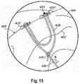
FIG. 1 is a projected view of an embodiment of the delivery device of the present invention.FIG. 2A is a side view of an embodiment of the delivery device shown inFIG. 1 .FIG. 2B is a top view of an embodiment of the delivery device shown inFIG. 1 .FIG. 3A is a sectional view of an embodiment of the delivery device shown inFIG. 2A taken along the line A-A.FIG. 3B is a sectional view of an embodiment of the delivery device shown inFIG. 2B taken along the line B-B.FIG. 4 is a sectional view of an embodiment of the delivery device shown inFIG. 2B taken along the line C-C.FIG. 5 is a side view of an embodiment of the driver mechanism for use in the delivery device ofFIG. 1 .FIG. 6A is a side view of an embodiment of the delivery device shown inFIG. 1 .FIG. 6B is a top view of an embodiment of the delivery device shown inFIG. 1 .FIG. 7A is a sectional view of an embodiment of the delivery device shown inFIG. 6A taken along the line D-D.FIG. 7B is a sectional view of an embodiment of the delivery device shown inFIG. 6B taken along the line E-E.FIG. 8 is a sectional view of an embodiment of the delivery device shown inFIG. 6B taken along the line F-F.FIG. 9A is a side view of an embodiment of the delivery device shown inFIG. 1 .FIG. 9B is a top view of an embodiment of the delivery device shown inFIG. 1 .FIG. 10A is a sectional view of an embodiment of the delivery device shown inFIG. 9A taken along the line G-G.FIG. 10B is a sectional view of an embodiment of the delivery device shown inFIG. 9B taken along the line H-H.FIG. 11 is a sectional view of an embodiment of the delivery device shown inFIG. 9B taken along the line I-I.FIG. 12 is a projected view of an embodiment of a suture anchor for use with the delivery device depicted inFig. 1 .FIG. 13A is a side view of an embodiment of a suture anchor for use with the delivery device depicted inFIG. 1 .FIG. 13B is a top view of an embodiment of a suture anchor for use with the delivery device depicted inFIG. 1 .FIG. 13C is a back view of an embodiment of a suture anchor for use with the delivery device depicted inFIG. 1 .FIG. 14 is a top partial sectional view of an embodiment of the delivery device depicted inFIG. 1 , showing two suture anchors.FIG. 15 is a view of an embodiment of the suture holding system having two suture anchors being used to repair a tear in soft tissue.FIG. 16 is a projected partial view of an embodiment of the suture holding system, including an embodiment of the delivery device depicted inFIG. 1 .- An embodiment of a
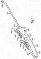
delivery device 300, according to the present invention, is shown inFigure 1 . Thedelivery device 300 includes ahousing 310, which may be formed in two separate pieces and connected together or may be formed as one continuous piece, with first 312 and second 314 driver mechanisms coupled thereto for independently deploying two suture anchors (not shown). Thedriver mechanisms top surface 324 of thehousing 310 and include first 316 and second 318 pushers.Grips 326 may be provided on thepushers finger hold 328 may also be provided on thebottom surface 330 of thehousing 310. As shown in detail inFigure 5 , first 312 and second 314 driver mechanisms also include first 344 and second 346 fins, respectively, extending downwardly from thepushers fins channels - First 332 and second 334 delivery needles for carrying the two suture anchors are coupled to the
driver mechanisms cannula 336 which may be provided at adistal end 338 of thehousing 310. Thedistal end 342 of thecannula 336 may be forked to allow for passage of a suture connecting the two anchors. Additionally, the distal end of thecannula 342 and the distal end of theneedles top surface 324 of the housing for assisting the surgeon. - The
improved delivery device 300 also includes acontrol mechanism 348 for controlling the sequence of deployment of thedriver mechanisms control mechanism 348 ensures that thefirst driver mechanism 312 is deployed before thesecond driver mechanism 314, such that the first suture anchor is implanted before the second suture anchor. This sequence of implantation is important for maintaining the orientation of the first suture anchor with respect to the second suture anchor so that the suture threaded between the two anchors does not become tangled, twisted or reversed, which will make tightening of the suture and repair of the torn tissue difficult, if not impossible. - Generally, the
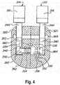
control mechanism 348 does not allow thesecond driver mechanism 314 to be advanced in a distal direction until thefirst driver mechanism 312 has been advanced to a fully extended position and the first suture anchor is implanted.Figures 2A, 2B ,3A, 3B and4 illustrate bothdriver mechanisms cannula 336. - In one embodiment, the
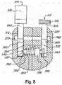
control mechanism 348 includes apin 350 slidably disposed in alateral bore 352 in thehousing 310. As shown inFigure 3A , when thefirst driver mechanism 312 is fully retracted,spring 354 keeps thehead 356 ofpin 350 biased towards thefin 344 of the first driver mechanism. In this position, one end of thepin 350 lies distal of thefin 346 of thesecond driver mechanism 314, preventing it from moving in a distal direction. Thepin 350 also includes astop 358, having a diameter conforming approximately to the diameter of thebore 352 and is larger than the diameter of thebody portion 360 of the pin. Figures 6A, 6B ,7A, 7B and8 illustrate thefirst driver mechanism 312 in a fully extended position, while thesecond driver mechanism 314 remains in a fully retracted position. Until thefirst driver mechanism 312 is moved into this position, thesecond driver mechanism 314 cannot be advanced. As shown inFigure 7A , when thefirst driver mechanism 312 is fully advanced, thefin 344 is moved completely distal of thepin head 356, allowing clearance from thelateral bore 352, into thechannel 320.Spring 354, having been compressed in the locked position of thecontrol mechanism 348, now causes the pin to move laterally into thechannel 320. As shown inFigure 8 , atrack 364, which runs the length offin 344, is also provided. When the surgeon chooses to return thefirst driver mechanism 312 from the fully extended to the fully retracted position, thehead 356 will pass throughtrack 364. Oncepin 350 has moved laterally intochannel 320, the second end of the pin no longer blockssecond driver mechanism 314 from moving longitudinally inchannel 312 and the surgeon may implant the second suture anchor.- In
Figures 9A, 9B ,10A, 10B and11 ,first driver mechanism 312 has been returned to a fully retracted state and thesecond driver mechanism 314 is advanced to a fully extended state, thus allowing the surgeon to implant the second suture anchor. - The
delivery device 300 may also be provided with atoggle mechanism 366. It is often desirable for the surgeon to fix or lock a driver mechanism, and thus a delivery needle, in a particular position during the implantation procedure. For example, the surgeon may wish to fix the driver mechanism in a fully extended position, or in an intermediate position in between the fully retracted and fully extended positions. This ability to fix the driver mechanism provides additional rigidity to the delivery device in that the surgeon need not physically hold the pusher in the desired position. Further, the ability to fix the driver mechanism in an intermediate position, where the delivery needle is not fully extended, provides the surgeon with the flexibility to change the position of the needle within the tissue before the suture anchor is implanted. For safety and sterility reasons, it may also be desirable to fix the driver mechanisms in a fully retracted position so that they are not accidentally advanced prior to the surgical procedure, such as during packaging or shipping, or after the surgical procedure has been completed. - As shown in
Figure 3B , thetoggle mechanism 366 includes at least onetoggle channel detent 372, 374 positioned along and opening up to thechannel detents 372, 374 define the positions in which the surgeon may fix a driver mechanism. In one embodiment, thetoggle mechanism 366 includes threedetents 372, one defining a fully retracted position, a fully extended position and an intermediate position lying therebetween. To lock the driver mechanism in one of the preset positions,pin 376, 378, connected to thefin toggle 372, 374 of the desired position. To achieve this, aslit fin pin 376, 378 to essentially be squeezed together and pressed downward from a detent and intotoggle channel toggle mechanism 366 may be provided in one or both of thedriver mechanisms - One embodiment of a
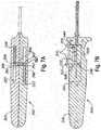
suture anchor 400 is shown inFigure 12 . Theanchor 400 includes at least twoeyelets 402 and alongitudinal channel 404 for receiving the distal end of adelivery needle channel 404 and at least a distal portion of theneedle anchor 400 from rotating on the needle. Theanchor 400 may also be provided with a taperedleading edge 406 to facilitate in implantation. - In operation, first and
second anchors 400, 400', with asuture 408 threaded therebetween, are loaded on toneedles shoulders Figure 14 . In one embodiment, a single strand ofsuture 408 is threaded through thefirst anchor 400 and then through the second anchor 400', with a locking slip-knot 414 connecting the two ends of suture. Thefree end 416 ofsuture 408 may be pulled in the direction of arrow A to tighten the loop of suture passing through thetissue 418 to closetear 420. Any other suitable knot may also be used. The suture, loaded on the anchors, may then pass out of thedistal end 342 of thecannula 336 through the slots therein, as shown inFigure 16 . - To implant the
anchors 400, 400', the surgeon positions thedelivery device 300 at the area of interest, for example, near a tear in a meniscus. The surgeon then engages thefirst driver mechanism 312, for example, by placing his/her thumb on thefirst pusher 316, and advances thefirst driver mechanism 312 in a distal direction thereby advancingfirst needle 332 carrying thefirst implant 400. As the surgeon advances thefirst driver mechanism 312, thefirst needle 332, which may have a pointed distal end, then enterstissue 418, crosses thetear 420, and continues until theneedle 332 exits thesurface 422 of the tissue. In the interim of this process, the surgeon may use thetoggle mechanism 366 to fix thedriver mechanism 312 at an intermediate position to, for example, determine if the needle is properly positioned across the tear. If the surgeon does not like the positioning, he may retract the needle and correct the placement. - Once the driver mechanism reaches its fully extended position, the
first anchor 400 will be disengaged from the first needle. The surgeon may also fix thefirst needle 332 in the fully extended position via thetoggle mechanism 366 while he/she, for example, disengages thefirst anchor 400 or adjusts thesuture 408. As described above, until thefirst driver mechanism 312 reaches the fully extended position, thecontrol mechanism 348 prevents thesecond driver mechanism 314 from advancing in a distal direction. The same procedure is used to implant the second suture anchor 400'. Once bothanchors 400, 400' are implanted, the surgeon may then pullfree end 416 of the suture in the direction of arrow A to tighten the length of suture between the implants and close thetear 420. - Additionally, in one embodiment, a
stop knot 420, which may be a single overhand knot, may also be provided in the length of suture between the eyelets 402' of the second suture anchor 400'. Thisstop knot 420 aids in tightening of the anchor construct. Without the knot, tightening of the construct can be difficult because of the multiple lengths of suture that pass through thetissue 418, which can cause the suture to get caught up and not slide well. With thestop knot 420, the length of the suture portion between the slip-knot 414 and stopknot 420 is fixed and not adjustable.
Claims (2)
- A suture anchor delivery system comprising:a housing (310) having a distal end and a proximal end, a first longitudinal channel (320), and a second longitudinal channel (322) substantially parallel to the first longitudinal channel; a first driver mechanism (312) slidably disposed in the first longitudinal channel, and a second driver mechanism (314) slidably disposed in the second longitudinal channel, such that each driver mechanism is movable in a longitudinal direction with respect to said housing (310);a first delivery needle (332) and a second delivery needle (334), said first delivery needle (332) connected at its proximal end to said first driver mechanism (312) and said second delivery needle (334) connected at its proximal end to said second driver mechanism (314);said first driver mechanism (312) and said second driver mechanism (314) each having fully retracted and fully extended longitudinal positions; anda control mechanism (348) operable to prevent said second driver mechanism (314) from being moved in a distal direction until said first driver mechanism (312) is longitudinally advanced to said fully extended position,characterized in that
the housing further comprises a lateral bore (352) in between, and opening into, the first and the second longitudinal channel, andin that the control mechanism (348) comprises a pin (350) having a head (356) and a body (360), said pin (350) being slidably disposed in the lateral bore such that the pin is movable in a lateral direction with respect to said housing (310), anda spring (354) received on the pin body (360) between the head and the housing, biasing the pin towards the first driver mechanism, the control mechanism (348) having a locked position inwhich the first driver mechanism (312) is in a longitudinally retracted position, wherein the spring (354) biases the pin head (356) laterally against the first driver mechanism (312), andin which at least a portion of the pin body (360) is positioned in the second longitudinal channel, distal of said second driver mechanism (314), thus preventing the second driver mechanism (314) from being longitudinally advanced in the second longitudinal channel in a distal direction,the control mechanism (348) further having an unlocked positionin which the first driver mechanism (312) is in its fully extended longitudinal position, wherein the spring biases the pin head (356) laterally into the first longitudinal channel into a position that is proximal to the first driver mechanism (312),so that the pin body does no longer prevent the second driver mechanism (314) from being longitudinally advanced in the second longitudinal channel in a distal direction. - The suture anchor delivery system of claim 1, wherein said control mechanism (348) is in a locked position until said first driver mechanism (312) is longitudinally advanced to said fully extended position and in an unlocked position after said first driver mechanism (312) is longitudinally advanced to said fully extended position.
Applications Claiming Priority (1)
| Application Number | Priority Date | Filing Date | Title |
|---|---|---|---|
| US13/707,229US9445806B2 (en) | 2009-02-06 | 2012-12-06 | Suture holder delivery system |
Publications (3)
| Publication Number | Publication Date |
|---|---|
| EP2740414A2 EP2740414A2 (en) | 2014-06-11 |
| EP2740414A3 EP2740414A3 (en) | 2014-08-20 |
| EP2740414B1true EP2740414B1 (en) | 2018-02-07 |
Family
ID=49886596
Family Applications (1)
| Application Number | Title | Priority Date | Filing Date |
|---|---|---|---|
| EP13195554.4AActiveEP2740414B1 (en) | 2012-12-06 | 2013-12-03 | Suture anchor delivery device |
Country Status (1)
| Country | Link |
|---|---|
| EP (1) | EP2740414B1 (en) |
Families Citing this family (2)
| Publication number | Priority date | Publication date | Assignee | Title |
|---|---|---|---|---|
| FR3086524B1 (en)* | 2018-09-28 | 2022-03-18 | S B M | DEVICE FOR FIXING AT LEAST ONE SUTURE THREAD IN A BIOLOGICAL TISSUE |
| RU209301U1 (en)* | 2021-07-29 | 2022-03-15 | Алексей Витальевич Мазалов | SUTURE HOLDER FOR ANCHOR SCREWDRIVER |
Family Cites Families (6)
| Publication number | Priority date | Publication date | Assignee | Title |
|---|---|---|---|---|
| US7153312B1 (en) | 1999-12-02 | 2006-12-26 | Smith & Nephew Inc. | Closure device and method for tissue repair |
| US6972027B2 (en) | 2002-06-26 | 2005-12-06 | Stryker Endoscopy | Soft tissue repair system |
| US7905904B2 (en) | 2006-02-03 | 2011-03-15 | Biomet Sports Medicine, Llc | Soft tissue repair device and associated methods |
| US8936614B2 (en)* | 2010-12-30 | 2015-01-20 | Covidien Lp | Combined unilateral/bilateral jaws on a surgical instrument |
| US8920436B2 (en)* | 2011-01-13 | 2014-12-30 | Usgi Medical, Inc. | Endoscopic tissue anchor deployment |
| AU2011354723B2 (en)* | 2011-01-14 | 2016-07-28 | Synthes Gmbh | Stitch lock for attaching two or more structures |
- 2013
- 2013-12-03EPEP13195554.4Apatent/EP2740414B1/enactiveActive
Non-Patent Citations (1)
| Title |
|---|
| None* |
Also Published As
| Publication number | Publication date |
|---|---|
| EP2740414A2 (en) | 2014-06-11 |
| EP2740414A3 (en) | 2014-08-20 |
Similar Documents
| Publication | Publication Date | Title |
|---|---|---|
| US9220493B2 (en) | Suture anchor kit | |
| US9445806B2 (en) | Suture holder delivery system | |
| EP2215972B1 (en) | Suture holding system | |
| US20210282772A1 (en) | Adjustable loop with locking knot | |
| JP6319778B2 (en) | Medical device and medical kit for attaching sutures to bone | |
| CA2737051C (en) | Method and apparatus for attaching soft tissue to bone | |
| US5810853A (en) | Knotting element for use in suturing anatomical tissue and methods therefor | |
| EP3097865B1 (en) | System for all-inside suture fixation for implant attachment and soft tissue repair | |
| US20220265266A1 (en) | Self-cinching suture construct apparatus | |
| AU2021204456A1 (en) | Transosseous suture anchor | |
| US20160345955A1 (en) | Systems and methods for repairing tissue | |
| JP7403539B2 (en) | System for repairing soft tissue tears | |
| EP3760134A1 (en) | A knot pusher | |
| MX2015004955A (en) | Flexible anchor delivery system. | |
| EP2822477A1 (en) | Suture-based knotless repair | |
| EP2740415B1 (en) | Suture holding system | |
| JP7171253B2 (en) | Finger rests for collapsible suture loops | |
| CN106333719A (en) | Device and method for suturing | |
| EP2740414B1 (en) | Suture anchor delivery device | |
| JP2025157437A (en) | System for repairing soft tissue tears |
Legal Events
| Date | Code | Title | Description |
|---|---|---|---|
| PUAI | Public reference made under article 153(3) epc to a published international application that has entered the european phase | Free format text:ORIGINAL CODE: 0009012 | |
| 17P | Request for examination filed | Effective date:20131203 | |
| AK | Designated contracting states | Kind code of ref document:A2 Designated state(s):AL AT BE BG CH CY CZ DE DK EE ES FI FR GB GR HR HU IE IS IT LI LT LU LV MC MK MT NL NO PL PT RO RS SE SI SK SM TR | |
| AX | Request for extension of the european patent | Extension state:BA ME | |
| PUAL | Search report despatched | Free format text:ORIGINAL CODE: 0009013 | |
| AK | Designated contracting states | Kind code of ref document:A3 Designated state(s):AL AT BE BG CH CY CZ DE DK EE ES FI FR GB GR HR HU IE IS IT LI LT LU LV MC MK MT NL NO PL PT RO RS SE SI SK SM TR | |
| AX | Request for extension of the european patent | Extension state:BA ME | |
| RIC1 | Information provided on ipc code assigned before grant | Ipc:A61B 17/04 20060101AFI20140717BHEP Ipc:A61B 17/06 20060101ALN20140717BHEP Ipc:A61B 17/00 20060101ALN20140717BHEP Ipc:A61B 17/064 20060101ALN20140717BHEP Ipc:A61B 19/00 20060101ALN20140717BHEP | |
| RIN1 | Information on inventor provided before grant (corrected) | Inventor name:ZANTOP, THORE Inventor name:HART, RICKEY | |
| R17P | Request for examination filed (corrected) | Effective date:20150212 | |
| RBV | Designated contracting states (corrected) | Designated state(s):AL AT BE BG CH CY CZ DE DK EE ES FI FR GB GR HR HU IE IS IT LI LT LU LV MC MK MT NL NO PL PT RO RS SE SI SK SM TR | |
| 17Q | First examination report despatched | Effective date:20150619 | |
| RIC1 | Information provided on ipc code assigned before grant | Ipc:A61B 17/00 20060101ALN20160421BHEP Ipc:A61B 17/06 20060101ALN20160421BHEP Ipc:A61B 17/064 20060101ALN20160421BHEP Ipc:A61B 17/04 20060101AFI20160421BHEP | |
| GRAP | Despatch of communication of intention to grant a patent | Free format text:ORIGINAL CODE: EPIDOSNIGR1 | |
| RIC1 | Information provided on ipc code assigned before grant | Ipc:A61B 17/00 20060101ALN20170518BHEP Ipc:A61B 17/04 20060101AFI20170518BHEP Ipc:A61B 17/06 20060101ALN20170518BHEP Ipc:A61B 17/064 20060101ALN20170518BHEP | |
| INTG | Intention to grant announced | Effective date:20170616 | |
| GRAS | Grant fee paid | Free format text:ORIGINAL CODE: EPIDOSNIGR3 | |
| GRAA | (expected) grant | Free format text:ORIGINAL CODE: 0009210 | |
| RAP1 | Party data changed (applicant data changed or rights of an application transferred) | Owner name:KARL STORZ SE & CO. KG | |
| AK | Designated contracting states | Kind code of ref document:B1 Designated state(s):AL AT BE BG CH CY CZ DE DK EE ES FI FR GB GR HR HU IE IS IT LI LT LU LV MC MK MT NL NO PL PT RO RS SE SI SK SM TR | |
| REG | Reference to a national code | Ref country code:GB Ref legal event code:FG4D | |
| REG | Reference to a national code | Ref country code:AT Ref legal event code:REF Ref document number:968483 Country of ref document:AT Kind code of ref document:T Effective date:20180215 Ref country code:CH Ref legal event code:EP | |
| REG | Reference to a national code | Ref country code:IE Ref legal event code:FG4D | |
| REG | Reference to a national code | Ref country code:DE Ref legal event code:R096 Ref document number:602013032916 Country of ref document:DE | |
| REG | Reference to a national code | Ref country code:NL Ref legal event code:MP Effective date:20180207 | |
| REG | Reference to a national code | Ref country code:AT Ref legal event code:MK05 Ref document number:968483 Country of ref document:AT Kind code of ref document:T Effective date:20180207 | |
| PG25 | Lapsed in a contracting state [announced via postgrant information from national office to epo] | Ref country code:LT Free format text:LAPSE BECAUSE OF FAILURE TO SUBMIT A TRANSLATION OF THE DESCRIPTION OR TO PAY THE FEE WITHIN THE PRESCRIBED TIME-LIMIT Effective date:20180207 Ref country code:CY Free format text:LAPSE BECAUSE OF FAILURE TO SUBMIT A TRANSLATION OF THE DESCRIPTION OR TO PAY THE FEE WITHIN THE PRESCRIBED TIME-LIMIT Effective date:20180207 Ref country code:NO Free format text:LAPSE BECAUSE OF FAILURE TO SUBMIT A TRANSLATION OF THE DESCRIPTION OR TO PAY THE FEE WITHIN THE PRESCRIBED TIME-LIMIT Effective date:20180507 Ref country code:FI Free format text:LAPSE BECAUSE OF FAILURE TO SUBMIT A TRANSLATION OF THE DESCRIPTION OR TO PAY THE FEE WITHIN THE PRESCRIBED TIME-LIMIT Effective date:20180207 Ref country code:NL Free format text:LAPSE BECAUSE OF FAILURE TO SUBMIT A TRANSLATION OF THE DESCRIPTION OR TO PAY THE FEE WITHIN THE PRESCRIBED TIME-LIMIT Effective date:20180207 Ref country code:HR Free format text:LAPSE BECAUSE OF FAILURE TO SUBMIT A TRANSLATION OF THE DESCRIPTION OR TO PAY THE FEE WITHIN THE PRESCRIBED TIME-LIMIT Effective date:20180207 Ref country code:ES Free format text:LAPSE BECAUSE OF FAILURE TO SUBMIT A TRANSLATION OF THE DESCRIPTION OR TO PAY THE FEE WITHIN THE PRESCRIBED TIME-LIMIT Effective date:20180207 | |
| PG25 | Lapsed in a contracting state [announced via postgrant information from national office to epo] | Ref country code:RS Free format text:LAPSE BECAUSE OF FAILURE TO SUBMIT A TRANSLATION OF THE DESCRIPTION OR TO PAY THE FEE WITHIN THE PRESCRIBED TIME-LIMIT Effective date:20180207 Ref country code:SE Free format text:LAPSE BECAUSE OF FAILURE TO SUBMIT A TRANSLATION OF THE DESCRIPTION OR TO PAY THE FEE WITHIN THE PRESCRIBED TIME-LIMIT Effective date:20180207 Ref country code:LV Free format text:LAPSE BECAUSE OF FAILURE TO SUBMIT A TRANSLATION OF THE DESCRIPTION OR TO PAY THE FEE WITHIN THE PRESCRIBED TIME-LIMIT Effective date:20180207 Ref country code:GR Free format text:LAPSE BECAUSE OF FAILURE TO SUBMIT A TRANSLATION OF THE DESCRIPTION OR TO PAY THE FEE WITHIN THE PRESCRIBED TIME-LIMIT Effective date:20180508 Ref country code:PL Free format text:LAPSE BECAUSE OF FAILURE TO SUBMIT A TRANSLATION OF THE DESCRIPTION OR TO PAY THE FEE WITHIN THE PRESCRIBED TIME-LIMIT Effective date:20180207 Ref country code:IS Free format text:LAPSE BECAUSE OF FAILURE TO SUBMIT A TRANSLATION OF THE DESCRIPTION OR TO PAY THE FEE WITHIN THE PRESCRIBED TIME-LIMIT Effective date:20180607 Ref country code:BG Free format text:LAPSE BECAUSE OF FAILURE TO SUBMIT A TRANSLATION OF THE DESCRIPTION OR TO PAY THE FEE WITHIN THE PRESCRIBED TIME-LIMIT Effective date:20180507 Ref country code:AT Free format text:LAPSE BECAUSE OF FAILURE TO SUBMIT A TRANSLATION OF THE DESCRIPTION OR TO PAY THE FEE WITHIN THE PRESCRIBED TIME-LIMIT Effective date:20180207 | |
| PG25 | Lapsed in a contracting state [announced via postgrant information from national office to epo] | Ref country code:AL Free format text:LAPSE BECAUSE OF FAILURE TO SUBMIT A TRANSLATION OF THE DESCRIPTION OR TO PAY THE FEE WITHIN THE PRESCRIBED TIME-LIMIT Effective date:20180207 Ref country code:EE Free format text:LAPSE BECAUSE OF FAILURE TO SUBMIT A TRANSLATION OF THE DESCRIPTION OR TO PAY THE FEE WITHIN THE PRESCRIBED TIME-LIMIT Effective date:20180207 Ref country code:RO Free format text:LAPSE BECAUSE OF FAILURE TO SUBMIT A TRANSLATION OF THE DESCRIPTION OR TO PAY THE FEE WITHIN THE PRESCRIBED TIME-LIMIT Effective date:20180207 | |
| REG | Reference to a national code | Ref country code:DE Ref legal event code:R097 Ref document number:602013032916 Country of ref document:DE | |
| PG25 | Lapsed in a contracting state [announced via postgrant information from national office to epo] | Ref country code:SK Free format text:LAPSE BECAUSE OF FAILURE TO SUBMIT A TRANSLATION OF THE DESCRIPTION OR TO PAY THE FEE WITHIN THE PRESCRIBED TIME-LIMIT Effective date:20180207 Ref country code:CZ Free format text:LAPSE BECAUSE OF FAILURE TO SUBMIT A TRANSLATION OF THE DESCRIPTION OR TO PAY THE FEE WITHIN THE PRESCRIBED TIME-LIMIT Effective date:20180207 Ref country code:DK Free format text:LAPSE BECAUSE OF FAILURE TO SUBMIT A TRANSLATION OF THE DESCRIPTION OR TO PAY THE FEE WITHIN THE PRESCRIBED TIME-LIMIT Effective date:20180207 Ref country code:SM Free format text:LAPSE BECAUSE OF FAILURE TO SUBMIT A TRANSLATION OF THE DESCRIPTION OR TO PAY THE FEE WITHIN THE PRESCRIBED TIME-LIMIT Effective date:20180207 | |
| PLBE | No opposition filed within time limit | Free format text:ORIGINAL CODE: 0009261 | |
| STAA | Information on the status of an ep patent application or granted ep patent | Free format text:STATUS: NO OPPOSITION FILED WITHIN TIME LIMIT | |
| 26N | No opposition filed | Effective date:20181108 | |
| PG25 | Lapsed in a contracting state [announced via postgrant information from national office to epo] | Ref country code:SI Free format text:LAPSE BECAUSE OF FAILURE TO SUBMIT A TRANSLATION OF THE DESCRIPTION OR TO PAY THE FEE WITHIN THE PRESCRIBED TIME-LIMIT Effective date:20180207 | |
| REG | Reference to a national code | Ref country code:CH Ref legal event code:PL | |
| PG25 | Lapsed in a contracting state [announced via postgrant information from national office to epo] | Ref country code:MC Free format text:LAPSE BECAUSE OF FAILURE TO SUBMIT A TRANSLATION OF THE DESCRIPTION OR TO PAY THE FEE WITHIN THE PRESCRIBED TIME-LIMIT Effective date:20180207 Ref country code:LU Free format text:LAPSE BECAUSE OF NON-PAYMENT OF DUE FEES Effective date:20181203 | |
| REG | Reference to a national code | Ref country code:IE Ref legal event code:MM4A | |
| REG | Reference to a national code | Ref country code:BE Ref legal event code:MM Effective date:20181231 | |
| PG25 | Lapsed in a contracting state [announced via postgrant information from national office to epo] | Ref country code:IE Free format text:LAPSE BECAUSE OF NON-PAYMENT OF DUE FEES Effective date:20181203 | |
| PG25 | Lapsed in a contracting state [announced via postgrant information from national office to epo] | Ref country code:BE Free format text:LAPSE BECAUSE OF NON-PAYMENT OF DUE FEES Effective date:20181231 | |
| PG25 | Lapsed in a contracting state [announced via postgrant information from national office to epo] | Ref country code:CH Free format text:LAPSE BECAUSE OF NON-PAYMENT OF DUE FEES Effective date:20181231 Ref country code:LI Free format text:LAPSE BECAUSE OF NON-PAYMENT OF DUE FEES Effective date:20181231 | |
| PG25 | Lapsed in a contracting state [announced via postgrant information from national office to epo] | Ref country code:MT Free format text:LAPSE BECAUSE OF NON-PAYMENT OF DUE FEES Effective date:20181203 | |
| PG25 | Lapsed in a contracting state [announced via postgrant information from national office to epo] | Ref country code:TR Free format text:LAPSE BECAUSE OF FAILURE TO SUBMIT A TRANSLATION OF THE DESCRIPTION OR TO PAY THE FEE WITHIN THE PRESCRIBED TIME-LIMIT Effective date:20180207 | |
| PG25 | Lapsed in a contracting state [announced via postgrant information from national office to epo] | Ref country code:PT Free format text:LAPSE BECAUSE OF FAILURE TO SUBMIT A TRANSLATION OF THE DESCRIPTION OR TO PAY THE FEE WITHIN THE PRESCRIBED TIME-LIMIT Effective date:20180207 | |
| PG25 | Lapsed in a contracting state [announced via postgrant information from national office to epo] | Ref country code:MK Free format text:LAPSE BECAUSE OF NON-PAYMENT OF DUE FEES Effective date:20180207 Ref country code:HU Free format text:LAPSE BECAUSE OF FAILURE TO SUBMIT A TRANSLATION OF THE DESCRIPTION OR TO PAY THE FEE WITHIN THE PRESCRIBED TIME-LIMIT; INVALID AB INITIO Effective date:20131203 | |
| P01 | Opt-out of the competence of the unified patent court (upc) registered | Effective date:20230527 | |
| PGFP | Annual fee paid to national office [announced via postgrant information from national office to epo] | Ref country code:GB Payment date:20241217 Year of fee payment:12 | |
| PGFP | Annual fee paid to national office [announced via postgrant information from national office to epo] | Ref country code:FR Payment date:20241227 Year of fee payment:12 | |
| PGFP | Annual fee paid to national office [announced via postgrant information from national office to epo] | Ref country code:DE Payment date:20241227 Year of fee payment:12 | |
| PGFP | Annual fee paid to national office [announced via postgrant information from national office to epo] | Ref country code:IT Payment date:20241220 Year of fee payment:12 |