EP2737864B1 - Receiving part for receiving a rod for coupling the rod to a bone anchoring element and a bone anchoring device - Google Patents
Receiving part for receiving a rod for coupling the rod to a bone anchoring element and a bone anchoring deviceDownload PDFInfo
- Publication number
- EP2737864B1 EP2737864B1EP14157391.5AEP14157391AEP2737864B1EP 2737864 B1EP2737864 B1EP 2737864B1EP 14157391 AEP14157391 AEP 14157391AEP 2737864 B1EP2737864 B1EP 2737864B1
- Authority
- EP
- European Patent Office
- Prior art keywords
- head
- receiving portion
- locking ring
- receiving part
- rod
- Prior art date
- Legal status (The legal status is an assumption and is not a legal conclusion. Google has not performed a legal analysis and makes no representation as to the accuracy of the status listed.)
- Active
Links
Images


Classifications
- A—HUMAN NECESSITIES
- A61—MEDICAL OR VETERINARY SCIENCE; HYGIENE
- A61B—DIAGNOSIS; SURGERY; IDENTIFICATION
- A61B17/00—Surgical instruments, devices or methods
- A61B17/56—Surgical instruments or methods for treatment of bones or joints; Devices specially adapted therefor
- A61B17/58—Surgical instruments or methods for treatment of bones or joints; Devices specially adapted therefor for osteosynthesis, e.g. bone plates, screws or setting implements
- A61B17/68—Internal fixation devices, including fasteners and spinal fixators, even if a part thereof projects from the skin
- A61B17/70—Spinal positioners or stabilisers, e.g. stabilisers comprising fluid filler in an implant
- A61B17/7001—Screws or hooks combined with longitudinal elements which do not contact vertebrae
- A61B17/7035—Screws or hooks, wherein a rod-clamping part and a bone-anchoring part can pivot relative to each other
- A61B17/7037—Screws or hooks, wherein a rod-clamping part and a bone-anchoring part can pivot relative to each other wherein pivoting is blocked when the rod is clamped
- A—HUMAN NECESSITIES
- A61—MEDICAL OR VETERINARY SCIENCE; HYGIENE
- A61B—DIAGNOSIS; SURGERY; IDENTIFICATION
- A61B17/00—Surgical instruments, devices or methods
- A61B17/56—Surgical instruments or methods for treatment of bones or joints; Devices specially adapted therefor
- A61B17/58—Surgical instruments or methods for treatment of bones or joints; Devices specially adapted therefor for osteosynthesis, e.g. bone plates, screws or setting implements
- A61B17/68—Internal fixation devices, including fasteners and spinal fixators, even if a part thereof projects from the skin
- A61B17/84—Fasteners therefor or fasteners being internal fixation devices
- A61B17/86—Pins or screws or threaded wires; nuts therefor
Definitions
- the inventionrelates to a receiving part for receiving a rod for coupling the rod to a bone anchoring element and a bone anchoring device with such a receiving part.
- the receiving partincludes a receiving part body with a rod receiving portion and a head receiving portion for receiving the head of the bone anchoring element and a locking ring for locking the head in the head receiving portion.
- the headcan be clamped by compressing a plurality of flexible wall sections with the locking ring wherein the clamping force is generated in a wall section at a circumferentially distinct pressure area.
- US 5,733,285describes a polyaxial colletted locking mechanism for use with an orthopaedic apparatus including a screw having a curvate head and a coupling element.
- the coupling elementhas a tapered and colletted portion having an interior chamber in which the curvate head is initially polyaxially disposed.
- a locking collaris disposed around the tapered and colletted portion such that translation thereof in the direction of the expanding taper causes the interior volume to contract onto the curvate head and lock it therein.
- WO 2007/038350 A2discloses an apparatus for connecting a bone anchor to a support rod, the apparatus including a connector body and a cap.
- the connector bodyhas a socket for insertion, angulation and removal of a bone anchor.
- a sleeveis provided which is configured to fit over the connector body for locking the bone anchor in the socket.
- EP 2 204 129 A1also discloses an apparatus for connecting a bone anchor to a support rod.
- the apparatuscomprises a receiving part body with a head receiving portion having an open end and being flexible so as to allow introduction and clamping of the head.
- the head receiving portionis provided with an outer tapered surface.
- a locking ring embracing the head receiving portionhas a tapered inner surface exerting a force onto the head receiving portion to lock the head therein.
- US 2001/004713 A1shows a device for connecting a longitudinal support to a bone anchor having a rounded head.
- the devicehas a lower portion with a chamber for receiving the rounded head.
- the lower portionhas a substantially spherical exterior surface.
- a sleeveis slidable over the body for compressing the chamber for biasing the longitudinal support.
- a lower sleeveacts as a clamping ring and it is fitted with a conical inside wall and is slidable over the exterior surface of a lower portion to compress the chamber.
- WO 2004/089245 A2describes a bone anchor having a bottom ring.
- the bottom ringsurrounds a lower portion of a housing provided to accept a rod and join it with the polyaxial bone anchor.
- the lower portionhas multiple resiliently opposed fingers and further comprises a convex outer surface.
- An inner surface of the bottom ringlies on the outside of the outer diameter of the lower portion.
- US 2002/0032443 A1discloses a multi-axial screw assembly including a bone screw mounted within a receiver member. A pair of shape-memory alloy locking rings is provided to clamp the receiver member about the bone screw.
- the receiving part according to the inventionis improved in view of the clamping and locking of the head. Exerting pressure by the locking ring at positions where the head receiving portion has slits does not contribute to an effective clamping of the head. Therefore, the bone anchoring device according to the present invention is designed such that the pressure force exerted by the locking ring onto the head receiving portion is concentrated onto distinct pressure areas separated from each other in circumferential direction. Hence, the clamping force can be precisely applied which improves the safety of the fixation.
- the receiving part according to the inventioncan have a pre-locking function wherein the locking ring is latched with respect to the receiving part body in a condition in which the head is inserted but not yet locked so that the head is prevented from removal.
- a modular systemcan be provided that allows to combine various anchoring elements with any suitable receiving part on demand depending on the actual clinical requirements.
- the bone anchoring deviceincludes a bone anchoring element 1 in the form of a bone screw having a threaded shaft 2 and a head 3 with a spherically-shaped outer surface portion.
- the head 3has a recess 4 for engagement with a driver.
- the bone anchoring devicefurther includes a receiving part body 5 for receiving a rod 100 to connect the rod 100 to the bone anchoring element 1.
- a locking ring 6is provided that engages the receiving part body 5.
- a fixation device in the form of an inner screw 7is provided for fixing the rod 100 in the receiving part body 5.
- Fig. 3cis a cross-sectional view wherein the section is being taken in a plane containing the rod axis
- Fig. 3dis a cross-sectional view wherein the section is taken perpendicular to the rod axis.
- the receiving part body 5comprises a rod receiving portion 9 which is substantially cylindrical and has a first end 9a and an opposite second end 9b and a central axis or cylinder axis C.
- a coaxial first bore 10is provided at the second end 9b. The diameter of the first bore 10 is smaller than the diameter of the head 3 of the bone anchoring element.
- a coaxial second bore 11extends from the first end 9a to a distance from the second end 9b.
- the diameter of the second 11is greater than that of the first bore 10.
- a substantially U-shaped recess 12extends from the first end 9a in the direction of the second end 9b in the rod receiving portion, the diameter of the recess 12 being slightly larger than the diameter of the rod 100 to allow placing the rod 100 in the recess and guiding it therein.
- the internal thread 13can be a metric thread, flat thread, a negative angle thread, a saw-tooth thread or any other thread form.
- a thread formsuch as a flat thread or a negative angle thread can be used which prevents splaying of the legs 12a, 12b when the inner screw 7 is tightened.
- the depth of the recess 12is such that the rod 100 and the inner screw 7 can be inserted between the legs 12a, 12b. It shall be noted that the diameter of the coaxial bore 11 can vary along the central axis C.
- cut-outs 15a,15bare provided in the rod receiving portion on either end of the channel formed by the recess 12.
- the receiving part body 5comprises a head receiving portion 17 providing an accommodation space for the head 3 of the bone anchoring element 1.
- the head receiving portion 17is substantially cylindrically-shaped with an outer diameter which is smaller than the greatest outer diameter of the rod receiving portion 9 such that the head receiving portion 17 is recessed with respect to the rod receiving portion 9 as can be best seen, for example in Figs. 3b) and 3c ).
- An internal hollow section 18 in the head receiving portion 17forms a seat for the head of the bone anchoring element 1.
- the hollow section 18is open via the opening 19 to a free end 17b of the head receiving portion.
- the hollow section 18is spherically shaped to accommodate the spherical head 3.
- the hollow section 18generally may be adapted to any other shape of the head 3 or can be shaped otherwise so as to allow locking of the head 3 in the head receiving portion 17.
- a plurality of slits 20are provided in the head receiving portion 17.
- the slits 20extend from the free end 17b to a distance from the second end 9b of the rod receiving portion.
- the slits 20extend over a region which includes the largest inner diameter of the hollow section 18.
- the slits 20render the head receiving portion 17 flexible so that it can be compressed to clamp and finally lock the head 3 in the internal hollow section 18 by friction.
- the head receiving portion 17is configured to allow the insertion of the head 3 by expanding the head receiving portion and to clamp and finally lock the head 3 by compressing the head receiving portion. 17.
- Some of the slits 20extend further into the rod receiving portion forming slits 20a as shown, for example, in Figs. 3a) and 3b ). By means of this, the insertion of the head 3 can be facilitated further.
- the pressure areais a distinct area seen in a circumferential direction within the flexible wall section 17a.
- the pressure areais formed by a tear drop-shaped projection 21 at the outer surface of each flexible wall section 17a.
- the tear drop-shaped projection 21is arranged at the center of the flexible wall section 17a in an axial direction and in a circumferential direction.
- the tear drop-shaped projection 21is oriented such that its height and width increases towards the open end 17b.
- the outer diameter of the head receiving portionincreases towards the free end 17b in the region of the tear drop-shaped projection as can be seen best in Fig. 3d ).
- an outwardly tapered pressure areais provided at each of the flexible wall sections 17a.
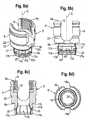
- Fig. 4ashows a perspective view of the locking ring 6.
- the locking ring 6is substantially cylindrical and has an upper end 6a and a lower end 6b. In the mounted state the upper end 6a is oriented in the direction of the first end 9a of the rod receiving portion and the lower end 6b is oriented towards the free end 17b of the head receiving portion. Adjacent the lower end 6b the locking ring 6 is substantially hollow cylindrically-shaped with an inner cylindrical surface 61, the diameter of which is slightly smaller than the outer diameter of the head receiving portion 17 in the region of the outermost area of the tear drop-shaped projection 21.
- the head receiving portion 17can be compressed to clamp and finally lock the head 3 when the locking ring 6 is around the head receiving portion 17.
- the lower end 6b of the locking ringmay have a rounded edge as shown, for example in Fig. 4d ) which shows a sectional view of the locking ring according line B-B in Fig. 4c ).
- Adjacent the cylindrical surface 61 the locking ring 6has a circular rim 62 with the upper end 6a. Between the circular rim 62 and the hollow cylindrical surface 61 an annular abutment surface 63 is formed.
- the height of the circular rim 62is such that when the locking ring 6 is in its lowermost position the rim 62 bridges the gap between the abutment surface 63 and the second end 9b as shown, in particular in Fig. 5b ). This may serve, for example, for preventing tissue growing into the gap between the abutment surface 63 and the second end 9b of the receiving part.
- the locking ring 6further has two projections 64 as shown in particular in Fig. 4a) and Fig. 4d ) which project from the abutment surface 63 towards the upper end 6a.
- the projections 64are offset from each other by 180° and may have a concave upper surface 64a for facilitating receiving the rod 100.
- All parts of the bone anchoring deviceare made of a bio-compatible material, for example of titanium, stainless steel or a bio-compatible alloy, such as Nitinol, or a bio-compatible plastic material such as, for example polyetheretherketone (PEEK).
- the partscan all be made of the same or of different materials.
- the assembly and use of the bone anchoring devicewill now be explained with reference to Figs. 5a) to 5c ).
- the locking ring 6is mounted from the free end 17b of the head receiving portion by compressing the flexible wall sections 17a.
- the locking ringis moved into a first position, which is the insertion position, shown in Fig. 5a ).
- the annular abutment surface 63abuts against the lower end 9b of the rod receiving portion 9.
- the locking ring 6is prevented from falling out, since the outer diameter of the head receiving portion 17 in the area of the highest point of the tear drop-shaped projection 21 is larger than the inner diameter of the cylindrical surface 61.
- the projections 64 of the locking ringaligned with the U-shaped recess 12. As can be seen in Fig. 5a ) in the first position, the projections 64 project above the bottom of the U-shaped recess 12.
- the anchoring element 1is inserted into a bone part or a vertebra.
- the recess 4 of the headcan be accessed with a driver through the first bore 10.
- the receiving partis still pivotable relative to the head 3 of the bone anchoring element 1.
- at least two bone anchoring devicesare used which are connected to the stabilization rod 100. After insertion of each of the bone anchoring devices, the receiving part bodies 5 are rotated and/or pivoted to be adjusted to receive the rod 100.
- the inner screw 7is screwed between the legs 12a, 12b until it presses onto the rod 100.
- the rod 100is thereby shifted towards the bottom of the U-shaped recess thereby engaging the upper surface 64a of the projections 64 and shifting down the locking ring 6.
- Fig. 5cwhich shows a cross-sectional view of the bone anchoring device with inserted rod and tightened inner screw 7 in a section containing the rod axis
- the locking ringdoes not engage the flexible wall section 17a other than at the distinct pressure areas realized by the tear drop-shaped projections 21.
- the pressureis applied only at the distinct pressure areas which are evenly distributed in a circumferential direction. Pressure is not exerted at positions which do not contribute to clamping the head such as the slits 20. Therefore, the efficiency of applying the clamping force is increased.
- the bone anchoring device of the second examplediffers from the bone anchoring device according to the first embodiment essentially be the design of the pressure area and of the locking ring.
- the receiving part body 5'has at its outer surface of the rod receiving portion 9 an engagement portion for the locking ring in the form of a circumferential groove 22 and a cylindrical portion 23 with slightly reduced diameter compared to the substantially cylindrical portion on the upper side of the groove 22.
- the groove 22acts as a stop for the locking ring in a second position which is a pre-locking position described below.
- the head receiving portion 17comprises the pressure areas which are realized by a ball bearing 21' provided in each flexible wall section, respectively.
- the head receiving portion 17has a first cylindrical section 17c with a first diameter adjacent the second end 9b of the rod receiving portion and a second cylindrical portion 17d with a second diameter greater than the first diameter which has the ball bearing 21'.
- a third portion 17e with a diameter that is essentially the same as that of the second portion 17cis provided at the free end 17b.
- a groove 24is provided that serves for engagement with a portion of the locking ring. It shall be noted that the grooves 22 and 24 may have an inclined lower edge which is inclined towards the free end 17b to facilitate disengagement of the locking ring when moving downwards.
- the second portion 17cis substantially at a position around the largest diameter of the hollow internal section 18 which corresponds to the largest outer diameter of the head 3 when it is inserted into the hollow interior section 18.
- the slits 20'preferably extend from the free end 17b only as far as the upper end of the second portion 17d, as for example, shown in Figs. 8b) and 8c ).
- Each of the flexible wall sections 17acomprises a distinct pressure area in form of a ball bearing21' at its center in a circumferential direction.
- Each ball bearing 21'includes a recess 25 having a substantially circular cross section which is sized and shaped to accommodate a ball 26 therein. The ball 26 can rotate in the recess and a portion of the ball projects out of the second cylindrical portion 17d. As soon as the locking ring is mounted the balls cannot fall out.
- the receiving part body 5'comprises in a circumferential direction equidistantly spaced balls 26 that cooperate with the locking ring.
- the locking ring 6'is substantially cylindrical and has the upper end 6a and the lower end 6b. Near the lower end 6b an inwardly projecting circular edge 610 is provided that cooperates with the third portion we adjacent the free end 17b of the head receiving portion 17.
- the inwardly projecting edge 610provides a cylindrical inner surface. Furthermore, the inwardly projecting edge 610 is configured to engage the groove 24 of the head receiving portion 17.
- the locking ring 6'Adjacent the inwardly projecting edge 610 the locking ring 6' comprises a hollow cylindrical portion 611 the height of which is such that it can receive the portions of the balls 26 protruding out of the recesses 25, as can be seen in particular in Fig. 10a ). Hence, the inner diameter is larger than the inner diameter of the inwardly projecting edge 610. Adjacent the hollow cylindrical portion 611, there is a hollow cylindrical portion 612, the inner diameter of which is smaller than the inner diameter of the hollow cylindrical portion 611 and larger than the inner diameter of the inwardly projecting edge 610. The inner diameter of the hollow cylindrical portion 612 is such that, as can be seen in Fig. 10b ) when the locking ring is around the head receiving portion 17 such that the hollow cylindrical portion 612 is arranged around the balls 26, the inner surface of the hollow cylindrical portion 612 can slide along the balls of the ball bearing.
- the upper portion of the locking ring 6' adjacent the upper end 6aconsists of upwardly extending wall portions 613 which are separated from each other by slits 614.
- the upwardly extending wall portions 613are arranged at the outer circumference of an inner circumferential shoulder 615 of the locking ring and render the upper portion of the locking ring flexible.
- the number and the size of the slits and the thickness of the wall portions 613are configured such that a desired flexibility is obtained.
- the wall portions 613comprise engagement sections 613 a which are shaped so as to engage the groove 22 provided on the outer surface of the rod receiving portion 9.
- the locking ring 6'is sized in such a way with respect to the head receiving portion 17 that the head receiving portion 17 can expand within the locking ring 6' to allow the introduction of the head 3 when the locking rings in the first position as shown in Fig. 10a ).
- Two projections 64which may have a concave upper surface portion 64a are provided at 180° offset from each other like in the locking ring 6 of the first embodiment.
- the curvature of the upper surface 64amay correspond to the curvature of the rod 100.
- the projections 64have such a height that they project above the bottom of the U-shaped recess 12 and extend into the cut-outs 15a, 15b, when the locking ring 6' is in a position in which the head 3 is not yet locked as shown in Figs. 10a) and 10b ).
- the height of the upwardly extending wall portions 613is such that when the locking ring is in a first position shown in Fig.
- the locking ringmay be tapered towards its lower end 6b to reduce the outer dimension of the receiving part.
- a first position of the locking ring 6'which is the insertion position in which the locking ring 6' is latched with respect to the receiving part body 5', is defined in such a way that the inwardly projecting edge 610 engages the groove 24 at the outer surface of the head receiving portion 17.
- the head 3can be inserted through the opening 19 into the hollow internal section 18 of the head receiving portion 17. Since the inner diameter of the inwardly projecting edge 610 is larger than the outer diameter of the groove 24, an expansion of the head receiving portion 17 when the head 3 is introduced is possible.
- the locking ring 6'is additionally held by a clamping force between the rod receiving portion 9 and the flexible wall portions 613 of the locking ring 6' which are slightly bent outwards as can be seen in particular in Fig. 10a ).
- the head receiving portion 17When the locking ring is in the first position, the head receiving portion 17 is not compressed. In this position, the locking ring is prevented from moving upwards towards the first end 9a of the rod receiving portion, since it abuts with the shoulder 615 against the second end 9b of the head receiving portion and with the inwardly projecting edge 610 against the upper wall of the groove 24. This holds the locking ring 6' in place.
- the inclined lower edge of the groove 24prevents an inadvertent downward movement of the locking ring 6' but allows a downward movement upon exertion of an additional downwardly directed force.
- the headIn the first position, the head can freely pivot in the hollow internal section 18. The head receiving portion is not compressed and the balls 26 are not touched, since they project into the hollow cylindrical portion 611.
- a second position, in which the locking ring 6' is latched with respect to the receiving part body 5'is shown in Fig. 10b ).
- a second positionis a pre-locking position in which the head 3 is prevented from removal from the hollow internal section 18 and optionally is held in a preliminary angular position by a slight friction force exerted by the flexible wall section 17a.
- the locking ring 6'has been shifted towards the free end 17b of the head receiving portion until the engagement portion 613a of the upwardly extending wall portion 613 resiliently snap into the groove 22 provided at the rod receiving portion 9.
- the free upper edge of the engagement portions 613aabut against the upper wall of the groove 22, as shown in Fig.
- the inclined lower edge of the groove 22prevents inadvertent downward movement of the locking towards the free end 17b but allows such downward movement upon exertion of an additional axial force.
- the locking 6'has to be shifted downwards. While the locking ring is shifted downwards the hollow cylindrical portion 612 slides along the rotating balls 26, thereby exerting pressure onto the flexible wall section 17a at the position of the balls 26. Hence, a jamming of the two cylindrical surfaces 17d of the head receiving portion and the hollow cylindrical portion 612 of the locking ring is prevented while simultaneously pressure is exerted onto the balls 26 which project out from the surface 17d.
- the balls 26define distinct pressure areas to exert the pressure onto the head 3 to clamp and finally lock the head 3.
- the bone anchoring elementIn the pre-locked position, the bone anchoring element cannot be removed from the receiving part. Hence, an accidental or inadvertent removal of the head is not possible. However, an angulation of the screw element is still possible by overcoming the friction force, for example manually.
- a third positionwhich is the locking position, is shown in Fig. 10c ).
- the third positionis defined as the position in which the head 3 is finally locked within the receiving portion 17.
- the inwardly projecting edge 610compresses the third portion 17e adjacent the free end 17b of the head receiving portion 17.
- the combination of the pressure exerted via the pressure areas in form of the balls 26 and the pressure exerted via the inwardly projecting edge 610firmly locks the head 3 within the receiving part body 5.
- the third positionis reached by a downward movement of the locking ring upon the action of the rod 100 pressing the upper surface of the projections 64. The rod is pressed downward when tightening the fixation screw 7.
- a third example of the bone anchoring devicewill now be described with reference to Figs. 11 to 15c ). Parts and portions which are the same or similar to those of the first embodiment and the second example are designated with same reference numerals and the description thereof will not be repeated.
- the third example of the bone anchoring devicediffers from the first embodiment and the second example by the design of the pressure areas.
- pressure areas 21"are defined as circumferentially distinct projections which are located at an inner side of the locking ring 6".
- the receiving part body 5"has a head receiving portion 17 similar to that of the second example.
- the second cylindrical portion 17d'is provided at an axial position of the head receiving portion 17 which corresponds substantially to the largest outer diameter of the head 3.
- the slits 20extend as in the first embodiment and the second example from the free end 17b to a distance from the second end 9b of rod receiving portion and on top of the second cylindrical portion 17d'.
- the locking ring 6"differs from the locking ring according to the second example in such a way that is has pressure areas in the form of circumferentially distinct projections 620 which are at an axial position corresponding to the position of the second cylindrical portion 17d' when the locking ring is in the third position as shown in Fig. 15c ).
- the projections 620project to the inside of the locking ring. Their number corresponds to the number of flexible wall segments 17a and the distance corresponds to the distance of the flexible wall sections 17a so that when the locking ring is mounted each projection 620 can engage one flexible wall section 17a.
- the projections 620have a height in axial direction which is approximately the same as the height of the second cylindrical portion 17d'.
- the projectionscan be generated by providing cut-outs of a projecting ring with inclined cutting surfaces 620a as shown in Fig. 14a) and Fig. 14d ). However, other shapes are possible which are configured to generate a distinct pressure area with respect to the flexible wall sections 17a. Assembly and use of the bone anchoring device according to the third example is similar to that of the second example. As shown in Fig. 15a ) in the first position, the inwardly projecting edge 610 of the locking ring 6" engages the groove 24 at the head receiving portion 17. The head can be introduced from the free end 17b.
- the engagement portions 613aengage the groove 22 at the rod receiving portion.
- the projections 620 of the lockingbegin to press against the second cylindrical portion 17d' of the head receiving portion 17.
- the projections 620are positioned substantially at the center of the second cylindrical portion 17d' and compress the flexible wall sections 17a to clamp the head 3.
- the inwardly projecting edge 610engages the third cylindrical portion 17e. The combination of pressure of the projections 620 and the inwardly projecting edge 610 the head is firmly locked within the hollow internal section 18.
- Single features of the embodiment describedcan be combined or exchanged with features of other examples.
- the locking ring and the receiving part of the first embodimentcan also be configured to have a pre-locking function and the locking ring and the receiving part of the second and third examplescan be designed without pre-locking function.
- the head of the bone anchoring elementcan have another shape, such as, for example, a cylindrical shape, whereby a mono-axial bone screw is provided allowing rotation of the screw element with respect to the receiving part body around a single axis.
- the projections forming the pressure areascan have any shape. Preferably, they have a rounded shape to facilitate movement of the locking ring.
- the head receiving portioncan have an inclined open end or can be otherwise asymmetric to allow a greater angulation of the head in one direction.
- anchoring elementall kinds of anchoring elements can be used and combined with the receiving part.
- These anchoring elementsare e.g. screws of different length, with different diameters, cannulated screws, screws with different thread forms, nails, hooks and anchoring elements wherein the head and the shaft are separate parts, etc.
- the rod receiving portionmay also have a different shape.
- the recesscan be configured to allow the rod to be introduced from the side instead of being introduced from the top.
- the recesscan also be closed instead of U-shaped.
- Various kinds of locking devicesincluding two- or more-part locking device, outer nuts, outer caps, bayonet locking devices or others are possible.
Landscapes
- Health & Medical Sciences (AREA)
- Orthopedic Medicine & Surgery (AREA)
- Life Sciences & Earth Sciences (AREA)
- Surgery (AREA)
- Neurology (AREA)
- Heart & Thoracic Surgery (AREA)
- Engineering & Computer Science (AREA)
- Biomedical Technology (AREA)
- Nuclear Medicine, Radiotherapy & Molecular Imaging (AREA)
- Medical Informatics (AREA)
- Molecular Biology (AREA)
- Animal Behavior & Ethology (AREA)
- General Health & Medical Sciences (AREA)
- Public Health (AREA)
- Veterinary Medicine (AREA)
- Surgical Instruments (AREA)
Description
- The invention relates to a receiving part for receiving a rod for coupling the rod to a bone anchoring element and a bone anchoring device with such a receiving part. The receiving part includes a receiving part body with a rod receiving portion and a head receiving portion for receiving the head of the bone anchoring element and a locking ring for locking the head in the head receiving portion. The head can be clamped by compressing a plurality of flexible wall sections with the locking ring wherein the clamping force is generated in a wall section at a circumferentially distinct pressure area.
US 5,733,285 describes a polyaxial colletted locking mechanism for use with an orthopaedic apparatus including a screw having a curvate head and a coupling element. The coupling element has a tapered and colletted portion having an interior chamber in which the curvate head is initially polyaxially disposed. A locking collar is disposed around the tapered and colletted portion such that translation thereof in the direction of the expanding taper causes the interior volume to contract onto the curvate head and lock it therein.WO 2007/038350 A2 discloses an apparatus for connecting a bone anchor to a support rod, the apparatus including a connector body and a cap. The connector body has a socket for insertion, angulation and removal of a bone anchor. A sleeve is provided which is configured to fit over the connector body for locking the bone anchor in the socket.EP 2 204 129 A1US 2001/004713 A1 shows a device for connecting a longitudinal support to a bone anchor having a rounded head. The device has a lower portion with a chamber for receiving the rounded head. The lower portion has a substantially spherical exterior surface. A sleeve is slidable over the body for compressing the chamber for biasing the longitudinal support. A lower sleeve acts as a clamping ring and it is fitted with a conical inside wall and is slidable over the exterior surface of a lower portion to compress the chamber.WO 2004/089245 A2 describes a bone anchor having a bottom ring. The bottom ring surrounds a lower portion of a housing provided to accept a rod and join it with the polyaxial bone anchor. The lower portion has multiple resiliently opposed fingers and further comprises a convex outer surface. An inner surface of the bottom ring lies on the outside of the outer diameter of the lower portion.US 2002/0032443 A1 discloses a multi-axial screw assembly including a bone screw mounted within a receiver member. A pair of shape-memory alloy locking rings is provided to clamp the receiver member about the bone screw.- It is the object of the invention to provide an improved receiving part for receiving a rod for coupling the rod to a bone anchoring element and a bone anchoring device with such a receiving part which allows a save handling during surgery and a save fixation of the bone anchoring element and the rod.
- The object is solved by a receiving part according to claim 1 and bone anchoring device according to
claim 13. Further developments are given in the dependent claims. - The receiving part according to the invention is improved in view of the clamping and locking of the head. Exerting pressure by the locking ring at positions where the head receiving portion has slits does not contribute to an effective clamping of the head. Therefore, the bone anchoring device according to the present invention is designed such that the pressure force exerted by the locking ring onto the head receiving portion is concentrated onto distinct pressure areas separated from each other in circumferential direction. Hence, the clamping force can be precisely applied which improves the safety of the fixation.
- Furthermore, the receiving part according to the invention can have a pre-locking function wherein the locking ring is latched with respect to the receiving part body in a condition in which the head is inserted but not yet locked so that the head is prevented from removal.
- With the bone anchoring device, a modular system can be provided that allows to combine various anchoring elements with any suitable receiving part on demand depending on the actual clinical requirements. The reduces the costs of polyaxial screws, reduces the inventory and gives the surgeon a substantial choice of implants.
- Further features and advantages of the invention will become apparent from the description of embodiments by means of the accompanying drawings.
- In the drawings
- Fig. 1
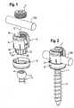
- shows a perspective exploded view of a first embodiment of the bone anchoring device.
- Fig. 2
- shows a perspective view of the bone anchoring device of
fig. 1 in an assembled state. - Fig. 3a) to 3e)
- show a perspective view, a side view, a first cross-sectional view, a second cross-sectional view and a bottom view, respectively, of the receiving part body of the bone anchoring device according to the first embodiment.
- Fig. 4a) to 4d)
- show a perspective view, a side view, a bottom view and a cross-sectional view, respectively, of the locking ring of the bone anchoring device according to the first embodiment.
- Fig. 5a) to 5c)
- show cross-sectional views of steps of use of the bone anchoring device according to the first embodiment.
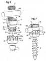
- Fig. 6
- shows a perspective exploded view of a second example of the bone anchoring device.
- Fig. 7
- shows a perspective view of the bone anchoring device of
Fig. 6 in an assembled state. - Fig. 8a) to 8d)
- show a perspective view, a side view, a cross-sectional view and a bottom view, respectively, of the receiving part body of the bone anchoring device of the second example.
- Fig. 9a) to 9d)
- show a perspective view, a bottom view, a side view and a cross-sectional view, respectively, of the locking ring of the bone anchoring device of the second example.
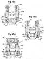
- Fig. 10a) to 10c)
- show cross-sectional views of steps of use of the bone anchoring device according to the second example.
- Fig: 1.1
- shows a perspective exploded view of a third example of the bone anchoring device.
- Fig. 12
- shows a perspective view of the bone anchoring device of
Fig. 11 in an assembled state. - Fig. 13a) to 13d)
- show a perspective view, a side view, a cross-sectional view and a bottom view, respectively, of the receiving part body of the bone anchoring device according to the third example.
- Fig. 14a) to 14d)
- show a perspective view, a bottom view, a side view and a cross-sectional view, respectively, of the locking ring of the bone anchoring device according to the third example.
- Fig. 15a) to 15c)
- show cross-sectional views of different steps of use of the bone anchoring device according to the third example.
- A first embodiment of a bone anchoring device illustrating the invention is shown in
Figs. 1 to 5c ). The remaining figures illustrate examples useful for understanding the invention. The bone anchoring device includes a bone anchoring element 1 in the form of a bone screw having a threadedshaft 2 and ahead 3 with a spherically-shaped outer surface portion. Thehead 3 has a recess 4 for engagement with a driver. The bone anchoring device further includes a receivingpart body 5 for receiving arod 100 to connect therod 100 to the bone anchoring element 1. For locking thehead 3 in the receiving part body 5 alocking ring 6 is provided that engages the receivingpart body 5. Furthermore, a fixation device in the form of aninner screw 7 is provided for fixing therod 100 in the receivingpart body 5. - In
Figs. 3a) to 3e), Fig. 3c ) is a cross-sectional view wherein the section is being taken in a plane containing the rod axis andFig. 3d ) is a cross-sectional view wherein the section is taken perpendicular to the rod axis. As shown in particular inFigs. 1 to 3e ), the receivingpart body 5 comprises arod receiving portion 9 which is substantially cylindrical and has afirst end 9a and an oppositesecond end 9b and a central axis or cylinder axis C. A coaxialfirst bore 10 is provided at thesecond end 9b. The diameter of thefirst bore 10 is smaller than the diameter of thehead 3 of the bone anchoring element. A coaxialsecond bore 11 extends from thefirst end 9a to a distance from thesecond end 9b. The diameter of the second 11 is greater than that of thefirst bore 10. A substantiallyU-shaped recess 12 extends from thefirst end 9a in the direction of thesecond end 9b in the rod receiving portion, the diameter of therecess 12 being slightly larger than the diameter of therod 100 to allow placing therod 100 in the recess and guiding it therein. By means of therecess 12 tofree legs internal thread 13 is provided. Theinternal thread 13 can be a metric thread, flat thread, a negative angle thread, a saw-tooth thread or any other thread form. If the fixation device is in form of theinner screw 7, a thread form such as a flat thread or a negative angle thread can be used which prevents splaying of thelegs inner screw 7 is tightened. The depth of therecess 12 is such that therod 100 and theinner screw 7 can be inserted between thelegs coaxial bore 11 can vary along the central axis C. - As can be seen in particular in
Figs. 3a) and 3e ) cut-outs recess 12. - At the side of the
second end 9b the receivingpart body 5 comprises ahead receiving portion 17 providing an accommodation space for thehead 3 of the bone anchoring element 1. Thehead receiving portion 17 is substantially cylindrically-shaped with an outer diameter which is smaller than the greatest outer diameter of therod receiving portion 9 such that thehead receiving portion 17 is recessed with respect to therod receiving portion 9 as can be best seen, for example inFigs. 3b) and 3c ). An internalhollow section 18 in thehead receiving portion 17 forms a seat for the head of the bone anchoring element 1. Thehollow section 18 is open via theopening 19 to afree end 17b of the head receiving portion. In the embodiment shown, thehollow section 18 is spherically shaped to accommodate thespherical head 3. However, thehollow section 18 generally may be adapted to any other shape of thehead 3 or can be shaped otherwise so as to allow locking of thehead 3 in thehead receiving portion 17. - A plurality of
slits 20 are provided in thehead receiving portion 17. Theslits 20 extend from thefree end 17b to a distance from thesecond end 9b of the rod receiving portion. Generally, theslits 20 extend over a region which includes the largest inner diameter of thehollow section 18. Theslits 20 render thehead receiving portion 17 flexible so that it can be compressed to clamp and finally lock thehead 3 in the internalhollow section 18 by friction. Thehead receiving portion 17 is configured to allow the insertion of thehead 3 by expanding the head receiving portion and to clamp and finally lock thehead 3 by compressing the head receiving portion. 17. Some of theslits 20 extend further into the rod receivingportion forming slits 20a as shown, for example, inFigs. 3a) and 3b ). By means of this, the insertion of thehead 3 can be facilitated further. - By the
slits flexible wall sections 17a of thehead receiving portion 17 are formed. On each of theflexible wall sections 17a a pressure area is formed in which the pressure generated by the cooperation with thelocking ring 6 with thehead receiving portion 17 is applied to thehead 3. The pressure area is a distinct area seen in a circumferential direction within theflexible wall section 17a. In the first embodiment, the pressure area is formed by a tear drop-shapedprojection 21 at the outer surface of eachflexible wall section 17a. The tear drop-shapedprojection 21 is arranged at the center of theflexible wall section 17a in an axial direction and in a circumferential direction. The tear drop-shapedprojection 21 is oriented such that its height and width increases towards theopen end 17b. By means of this, the outer diameter of the head receiving portion increases towards thefree end 17b in the region of the tear drop-shaped projection as can be seen best inFig. 3d ). Hence, an outwardly tapered pressure area is provided at each of theflexible wall sections 17a. - The
locking ring 6 will now be described with reference toFigs. 4a) to 4d). Fig. 4a ) shows a perspective view of thelocking ring 6. Thelocking ring 6 is substantially cylindrical and has anupper end 6a and alower end 6b. In the mounted state theupper end 6a is oriented in the direction of thefirst end 9a of the rod receiving portion and thelower end 6b is oriented towards thefree end 17b of the head receiving portion. Adjacent thelower end 6b thelocking ring 6 is substantially hollow cylindrically-shaped with an innercylindrical surface 61, the diameter of which is slightly smaller than the outer diameter of thehead receiving portion 17 in the region of the outermost area of the tear drop-shapedprojection 21. By means of this, thehead receiving portion 17 can be compressed to clamp and finally lock thehead 3 when thelocking ring 6 is around thehead receiving portion 17. Thelower end 6b of the locking ring may have a rounded edge as shown, for example inFig. 4d ) which shows a sectional view of the locking ring according line B-B inFig. 4c ). Adjacent thecylindrical surface 61 thelocking ring 6 has acircular rim 62 with theupper end 6a. Between thecircular rim 62 and the hollowcylindrical surface 61 anannular abutment surface 63 is formed. The height of thecircular rim 62 is such that when thelocking ring 6 is in its lowermost position therim 62 bridges the gap between theabutment surface 63 and thesecond end 9b as shown, in particular inFig. 5b ). This may serve, for example, for preventing tissue growing into the gap between theabutment surface 63 and thesecond end 9b of the receiving part. Thelocking ring 6 further has twoprojections 64 as shown in particular inFig. 4a) and Fig. 4d ) which project from theabutment surface 63 towards theupper end 6a. Theprojections 64 are offset from each other by 180° and may have a concaveupper surface 64a for facilitating receiving therod 100. - All parts of the bone anchoring device are made of a bio-compatible material, for example of titanium, stainless steel or a bio-compatible alloy, such as Nitinol, or a bio-compatible plastic material such as, for example polyetheretherketone (PEEK). The parts can all be made of the same or of different materials.
- The assembly and use of the bone anchoring device will now be explained with reference to
Figs. 5a) to 5c ). Thelocking ring 6 is mounted from thefree end 17b of the head receiving portion by compressing theflexible wall sections 17a. Next, the locking ring is moved into a first position, which is the insertion position, shown inFig. 5a ). In this position, theannular abutment surface 63 abuts against thelower end 9b of therod receiving portion 9. Between the innercylindrical surface 61 and the outer surface of thehead receiving portion 17 there is a gap which allows the expansion of theflexible wall section 17a to some extent. In this condition, thehead 3 can be inserted from thefree end 17b by expanding the hollowinternal section 18. Once thehead 3 is inserted to the hollowinternal section 18, thelocking ring 6 is prevented from falling out, since the outer diameter of thehead receiving portion 17 in the area of the highest point of the tear drop-shapedprojection 21 is larger than the inner diameter of thecylindrical surface 61. Theprojections 64 of the locking ring aligned with theU-shaped recess 12. As can be seen inFig. 5a ) in the first position, theprojections 64 project above the bottom of theU-shaped recess 12. - In this condition, which can be achieved by preassembling the receiving
part body 5, thelocking ring 6 and the anchoring element 1, the anchoring element 1 is inserted into a bone part or a vertebra. The recess 4 of the head can be accessed with a driver through thefirst bore 10. In the condition shown inFig. 5a ) the receiving part is still pivotable relative to thehead 3 of the bone anchoring element 1. Usually, at least two bone anchoring devices are used which are connected to thestabilization rod 100. After insertion of each of the bone anchoring devices, the receivingpart bodies 5 are rotated and/or pivoted to be adjusted to receive therod 100. Once the correct position of the rod with respect to the bone anchoring devices is achieved, theinner screw 7 is screwed between thelegs rod 100. Therod 100 is thereby shifted towards the bottom of the U-shaped recess thereby engaging theupper surface 64a of theprojections 64 and shifting down thelocking ring 6. - When the
locking ring 6 is shifted towards thefree end 17b of the head receiving portion its cylindricalinner surface 62 engages the outwardly tapering surface of the tear drop-shapedprojections 21, thereby creating an increasing pressure onto theflexible wall sections 17a. When the locking ring has been fully moved downwards the pressure exerted by the locking ring onto the flexible wall sections is such that thehead 3 is finally locked in the hollowinternal section 18. - As can be seen in
Fig. 5c ) which shows a cross-sectional view of the bone anchoring device with inserted rod and tightenedinner screw 7 in a section containing the rod axis, the locking ring does not engage theflexible wall section 17a other than at the distinct pressure areas realized by the tear drop-shapedprojections 21. On other areas, there is a gap between the parallel surfaces of the innercylindrical surface 61 and theflexible wall sections 17a. Hence, the pressure is applied only at the distinct pressure areas which are evenly distributed in a circumferential direction. Pressure is not exerted at positions which do not contribute to clamping the head such as theslits 20. Therefore, the efficiency of applying the clamping force is increased. - A second example of the bone anchoring device will now be described with reference to
Figs. 6 to 10c ). Parts and portions which are identical or similar to the parts and portions of the first embodiment are described by the same reference numerals and the description thereof will not be repeated. The bone anchoring device of the second example differs from the bone anchoring device according to the first embodiment essentially be the design of the pressure area and of the locking ring. - As can be seen in particular in
Figs. 1 and8a ) to 8d) the receiving part body 5' has at its outer surface of therod receiving portion 9 an engagement portion for the locking ring in the form of acircumferential groove 22 and a cylindrical portion 23 with slightly reduced diameter compared to the substantially cylindrical portion on the upper side of thegroove 22. Thegroove 22 acts as a stop for the locking ring in a second position which is a pre-locking position described below. - The
head receiving portion 17 comprises the pressure areas which are realized by a ball bearing 21' provided in each flexible wall section, respectively. Thehead receiving portion 17 has a firstcylindrical section 17c with a first diameter adjacent thesecond end 9b of the rod receiving portion and a secondcylindrical portion 17d with a second diameter greater than the first diameter which has the ball bearing 21'. Athird portion 17e with a diameter that is essentially the same as that of thesecond portion 17c is provided at thefree end 17b. Between thesecond portion 17d and thethird portion 17e agroove 24 is provided that serves for engagement with a portion of the locking ring. It shall be noted that thegrooves free end 17b to facilitate disengagement of the locking ring when moving downwards. Thesecond portion 17c is substantially at a position around the largest diameter of the hollowinternal section 18 which corresponds to the largest outer diameter of thehead 3 when it is inserted into the hollowinterior section 18. The slits 20' preferably extend from thefree end 17b only as far as the upper end of thesecond portion 17d, as for example, shown inFigs. 8b) and 8c ). - Each of the
flexible wall sections 17a comprises a distinct pressure area in form of a ball bearing21' at its center in a circumferential direction. Each ball bearing 21' includes arecess 25 having a substantially circular cross section which is sized and shaped to accommodate aball 26 therein. Theball 26 can rotate in the recess and a portion of the ball projects out of the secondcylindrical portion 17d. As soon as the locking ring is mounted the balls cannot fall out. As best seen inFigs. 6 and10a ) to 10c) the receiving part body 5' comprises in a circumferential direction equidistantly spacedballs 26 that cooperate with the locking ring. - The locking ring will now be described with respect to
Figs. 9a) to 9d ). The locking ring 6' is substantially cylindrical and has theupper end 6a and thelower end 6b. Near thelower end 6b an inwardly projectingcircular edge 610 is provided that cooperates with the third portion we adjacent thefree end 17b of thehead receiving portion 17. The inwardly projectingedge 610 provides a cylindrical inner surface. Furthermore, the inwardly projectingedge 610 is configured to engage thegroove 24 of thehead receiving portion 17. - Adjacent the inwardly projecting
edge 610 the locking ring 6' comprises a hollowcylindrical portion 611 the height of which is such that it can receive the portions of theballs 26 protruding out of therecesses 25, as can be seen in particular inFig. 10a ). Hence, the inner diameter is larger than the inner diameter of the inwardly projectingedge 610. Adjacent the hollowcylindrical portion 611, there is a hollowcylindrical portion 612, the inner diameter of which is smaller than the inner diameter of the hollowcylindrical portion 611 and larger than the inner diameter of the inwardly projectingedge 610. The inner diameter of the hollowcylindrical portion 612 is such that, as can be seen inFig. 10b ) when the locking ring is around thehead receiving portion 17 such that the hollowcylindrical portion 612 is arranged around theballs 26, the inner surface of the hollowcylindrical portion 612 can slide along the balls of the ball bearing. - The upper portion of the locking ring 6' adjacent the
upper end 6a consists of upwardly extendingwall portions 613 which are separated from each other byslits 614. The upwardly extendingwall portions 613 are arranged at the outer circumference of an innercircumferential shoulder 615 of the locking ring and render the upper portion of the locking ring flexible. The number and the size of the slits and the thickness of thewall portions 613 are configured such that a desired flexibility is obtained. At their free ends thewall portions 613 compriseengagement sections 613 a which are shaped so as to engage thegroove 22 provided on the outer surface of therod receiving portion 9. - The locking ring 6' is sized in such a way with respect to the
head receiving portion 17 that thehead receiving portion 17 can expand within the locking ring 6' to allow the introduction of thehead 3 when the locking rings in the first position as shown inFig. 10a ). - Two
projections 64 which may have a concaveupper surface portion 64a are provided at 180° offset from each other like in thelocking ring 6 of the first embodiment. The curvature of theupper surface 64a may correspond to the curvature of therod 100. Theprojections 64 have such a height that they project above the bottom of theU-shaped recess 12 and extend into the cut-outs head 3 is not yet locked as shown inFigs. 10a) and 10b ). The height of the upwardly extendingwall portions 613 is such that when the locking ring is in a first position shown inFig. 10a ) in which its inner circumferential shoulder abuts against thesecond end 9b, the upwardly extendingwall portion 613 are with theirengagement portion 613a above thecircumferential groove 22. At the outside, the locking ring may be tapered towards itslower end 6b to reduce the outer dimension of the receiving part. - The function and use of the bone anchoring device will now be explained with reference to
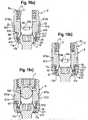
Figs. 10a) to 10c ). As shown inFig. 10a ), a first position of the locking ring 6', which is the insertion position in which the locking ring 6' is latched with respect to the receiving part body 5', is defined in such a way that the inwardly projectingedge 610 engages thegroove 24 at the outer surface of thehead receiving portion 17. In this condition, thehead 3 can be inserted through theopening 19 into the hollowinternal section 18 of thehead receiving portion 17. Since the inner diameter of the inwardly projectingedge 610 is larger than the outer diameter of thegroove 24, an expansion of thehead receiving portion 17 when thehead 3 is introduced is possible. In the first position, the locking ring 6' is additionally held by a clamping force between therod receiving portion 9 and theflexible wall portions 613 of the locking ring 6' which are slightly bent outwards as can be seen in particular inFig. 10a ). - When the locking ring is in the first position, the
head receiving portion 17 is not compressed. In this position, the locking ring is prevented from moving upwards towards thefirst end 9a of the rod receiving portion, since it abuts with theshoulder 615 against thesecond end 9b of the head receiving portion and with the inwardly projectingedge 610 against the upper wall of thegroove 24. This holds the locking ring 6' in place. The inclined lower edge of thegroove 24 prevents an inadvertent downward movement of the locking ring 6' but allows a downward movement upon exertion of an additional downwardly directed force. In the first position, the head can freely pivot in the hollowinternal section 18. The head receiving portion is not compressed and theballs 26 are not touched, since they project into the hollowcylindrical portion 611. - A second position, in which the locking ring 6' is latched with respect to the receiving part body 5' is shown in
Fig. 10b ). A second position is a pre-locking position in which thehead 3 is prevented from removal from the hollowinternal section 18 and optionally is held in a preliminary angular position by a slight friction force exerted by theflexible wall section 17a. In the second position, the locking ring 6' has been shifted towards thefree end 17b of the head receiving portion until theengagement portion 613a of the upwardly extendingwall portion 613 resiliently snap into thegroove 22 provided at therod receiving portion 9. The free upper edge of theengagement portions 613a abut against the upper wall of thegroove 22, as shown inFig. 10b ), thereby preventing upward movement of the locking ring out of the pre-locking position. On the other hand, the inclined lower edge of thegroove 22 prevents inadvertent downward movement of the locking towards thefree end 17b but allows such downward movement upon exertion of an additional axial force. - To reach the second position from the first position the locking 6' has to be shifted downwards. While the locking ring is shifted downwards the hollow
cylindrical portion 612 slides along therotating balls 26, thereby exerting pressure onto theflexible wall section 17a at the position of theballs 26. Hence, a jamming of the twocylindrical surfaces 17d of the head receiving portion and the hollowcylindrical portion 612 of the locking ring is prevented while simultaneously pressure is exerted onto theballs 26 which project out from thesurface 17d. Theballs 26 define distinct pressure areas to exert the pressure onto thehead 3 to clamp and finally lock thehead 3. - In the pre-locked position, the bone anchoring element cannot be removed from the receiving part. Hence, an accidental or inadvertent removal of the head is not possible. However, an angulation of the screw element is still possible by overcoming the friction force, for example manually.
- A third position, which is the locking position, is shown in
Fig. 10c ). The third position is defined as the position in which thehead 3 is finally locked within the receivingportion 17. The inwardly projectingedge 610 compresses thethird portion 17e adjacent thefree end 17b of thehead receiving portion 17. The combination of the pressure exerted via the pressure areas in form of theballs 26 and the pressure exerted via the inwardly projectingedge 610 firmly locks thehead 3 within the receivingpart body 5. The third position is reached by a downward movement of the locking ring upon the action of therod 100 pressing the upper surface of theprojections 64. The rod is pressed downward when tightening thefixation screw 7. - A third example of the bone anchoring device will now be described with reference to
Figs. 11 to 15c ). Parts and portions which are the same or similar to those of the first embodiment and the second example are designated with same reference numerals and the description thereof will not be repeated. The third example of the bone anchoring device differs from the first embodiment and the second example by the design of the pressure areas. In the thirdexample pressure areas 21" are defined as circumferentially distinct projections which are located at an inner side of thelocking ring 6". - As can be seen in particular in
Figs. 13a) to 13d ) the receivingpart body 5" has ahead receiving portion 17 similar to that of the second example. The secondcylindrical portion 17d' is provided at an axial position of thehead receiving portion 17 which corresponds substantially to the largest outer diameter of thehead 3. Theslits 20 extend as in the first embodiment and the second example from thefree end 17b to a distance from thesecond end 9b of rod receiving portion and on top of the secondcylindrical portion 17d'. - The
locking ring 6" differs from the locking ring according to the second example in such a way that is has pressure areas in the form of circumferentiallydistinct projections 620 which are at an axial position corresponding to the position of the secondcylindrical portion 17d' when the locking ring is in the third position as shown inFig. 15c ). Theprojections 620 project to the inside of the locking ring. Their number corresponds to the number offlexible wall segments 17a and the distance corresponds to the distance of theflexible wall sections 17a so that when the locking ring is mounted eachprojection 620 can engage oneflexible wall section 17a. Theprojections 620 have a height in axial direction which is approximately the same as the height of the secondcylindrical portion 17d'. Their width in a circumferential direction is smaller than the width of theflexible wall sections 17a thereby creating the distinct pressure area in eachflexible wall section 17a. The projections can be generated by providing cut-outs of a projecting ring withinclined cutting surfaces 620a as shown inFig. 14a) and Fig. 14d ). However, other shapes are possible which are configured to generate a distinct pressure area with respect to theflexible wall sections 17a. Assembly and use of the bone anchoring device according to the third example is similar to that of the second example. As shown inFig. 15a ) in the first position, the inwardly projectingedge 610 of thelocking ring 6" engages thegroove 24 at thehead receiving portion 17. The head can be introduced from thefree end 17b. - In the second position, which is the pre-locking position, as shown in
Fig. 15b ) theengagement portions 613a engage thegroove 22 at the rod receiving portion. In this position theprojections 620 of the locking begin to press against the secondcylindrical portion 17d' of thehead receiving portion 17. - In the third position, as shown in
Fig. 15c ), theprojections 620 are positioned substantially at the center of the secondcylindrical portion 17d' and compress theflexible wall sections 17a to clamp thehead 3. In addition, the inwardly projectingedge 610 engages the thirdcylindrical portion 17e. The combination of pressure of theprojections 620 and the inwardly projectingedge 610 the head is firmly locked within the hollowinternal section 18. - Single features of the embodiment described can be combined or exchanged with features of other examples. For example, it is possible to have the projections that form the distinct pressure areas on the flexible wall portions and on the locking ring alternately in a circumferential direction. The locking ring and the receiving part of the first embodiment can also be configured to have a pre-locking function and the locking ring and the receiving part of the second and third examplescan be designed without pre-locking function.
- Further modifications of the embodiments shown are possible. For example, the head of the bone anchoring element can have another shape, such as, for example, a cylindrical shape, whereby a mono-axial bone screw is provided allowing rotation of the screw element with respect to the receiving part body around a single axis.
- The projections forming the pressure areas can have any shape. Preferably, they have a rounded shape to facilitate movement of the locking ring.
- The head receiving portion can have an inclined open end or can be otherwise asymmetric to allow a greater angulation of the head in one direction.
- For the anchoring element, all kinds of anchoring elements can be used and combined with the receiving part. These anchoring elements are e.g. screws of different length, with different diameters, cannulated screws, screws with different thread forms, nails, hooks and anchoring elements wherein the head and the shaft are separate parts, etc.
- The rod receiving portion may also have a different shape. For example, the recess can be configured to allow the rod to be introduced from the side instead of being introduced from the top. The recess can also be closed instead of U-shaped. Various kinds of locking devices, including two- or more-part locking device, outer nuts, outer caps, bayonet locking devices or others are possible.
Claims (9)
- A receiving part for receiving a rod for coupling the rod to a bone anchoring element (1), the receiving part including
a receiving part body (5) with a top end (9a) and a bottom end (17b), and
a rod receiving portion (9) with a channel (12) for receiving the rod (100), and
a head receiving portion (17) for accommodating a head (3) of the bone anchoring element, the head receiving portion having an open end (19, 17b) for introducing the head (3); and
a locking ring (6) embracing the head receiving portion (17),
wherein the head receiving portion comprises a plurality of flexible wall portions (17a) and wherein the flexible wall portions (17a) and the locking ring (6) are configured to engage each other at circumferentially distinct pressure areas (21) within the flexible wall sections (17a), wherein
the distinct pressure areas are provided by tear drop-shaped projections (21),characterized in that the tear drop-shaped proj ections (21) are arranged at the centre of the flexible wall sections (17a) in an axial direction and in a circumferential direction. - The receiving part according to claim 1, wherein the flexible wall portions (17a) are separated by slits (20).
- The receiving part according to claim 1 or 2, wherein the distinct pressure areas include circumferentially separated projections (21, 26) which are provided at the flexible wall sections (17a).
- The receiving part of one of claims 1 to 3, wherein the tear drop-shaped projections are oriented such that the width and the height increases towards the open end (19, 17).
- The receiving part of one of claims 1 to 4, wherein the locking ring (6) has a lower end (6b) oriented towards a free end of the head receiving portion (17) and wherein, adjacent to the lower end (6b), the locking ring (6) is substantially hollow cylindrically-shaped with an inner cylindrical surface (61), the diameter of which is slightly smaller than an outer diameter of the head receiving portion (17) in the region of the outermost area of the tear drop-shaped projections (21).
- The receiving part of one of claims 1 to 5, wherein opposing surfaces of the head receiving portion (17) and the locking ring (6) other than at the distinct pressure areas are parallel.
- The receiving part of one of claims 1 to 6, wherein the distinct pressure areas are arranged substantially at the centre of the flexible wall portion (17a), respectively.
- The receiving part of one of claims 1 to 7, wherein the head receiving portion (17) includes a hollow internal section (18) for accommodating the head and wherein the distinct pressure areas (21) are located at a position of the largest inner diameter of the hollow internal section (18).
- A bone anchoring device including a receiving part according to claims 1 to 8 and a bone anchoring element (1) having a shaft (2) for anchoring in the bone and a head (15).
Priority Applications (1)
| Application Number | Priority Date | Filing Date | Title |
|---|---|---|---|
| EP14157391.5AEP2737864B1 (en) | 2010-12-10 | 2010-12-10 | Receiving part for receiving a rod for coupling the rod to a bone anchoring element and a bone anchoring device |
Applications Claiming Priority (2)
| Application Number | Priority Date | Filing Date | Title |
|---|---|---|---|
| EP10194596.2AEP2462886B1 (en) | 2010-12-10 | 2010-12-10 | Receiving part for receiving a rod for coupling the rod to a bone anchoring element and a bone anchoring device |
| EP14157391.5AEP2737864B1 (en) | 2010-12-10 | 2010-12-10 | Receiving part for receiving a rod for coupling the rod to a bone anchoring element and a bone anchoring device |
Related Parent Applications (1)
| Application Number | Title | Priority Date | Filing Date |
|---|---|---|---|
| EP10194596.2ADivisionEP2462886B1 (en) | 2010-12-10 | 2010-12-10 | Receiving part for receiving a rod for coupling the rod to a bone anchoring element and a bone anchoring device |
Publications (2)
| Publication Number | Publication Date |
|---|---|
| EP2737864A1 EP2737864A1 (en) | 2014-06-04 |
| EP2737864B1true EP2737864B1 (en) | 2017-04-12 |
Family
ID=43735791
Family Applications (2)
| Application Number | Title | Priority Date | Filing Date |
|---|---|---|---|
| EP14157391.5AActiveEP2737864B1 (en) | 2010-12-10 | 2010-12-10 | Receiving part for receiving a rod for coupling the rod to a bone anchoring element and a bone anchoring device |
| EP10194596.2AActiveEP2462886B1 (en) | 2010-12-10 | 2010-12-10 | Receiving part for receiving a rod for coupling the rod to a bone anchoring element and a bone anchoring device |
Family Applications After (1)
| Application Number | Title | Priority Date | Filing Date |
|---|---|---|---|
| EP10194596.2AActiveEP2462886B1 (en) | 2010-12-10 | 2010-12-10 | Receiving part for receiving a rod for coupling the rod to a bone anchoring element and a bone anchoring device |
Country Status (6)
| Country | Link |
|---|---|
| US (1) | US9066759B2 (en) |
| EP (2) | EP2737864B1 (en) |
| JP (1) | JP2012125565A (en) |
| KR (1) | KR20120065236A (en) |
| CN (1) | CN102525614B (en) |
| ES (1) | ES2473915T3 (en) |
Families Citing this family (44)
| Publication number | Priority date | Publication date | Assignee | Title |
|---|---|---|---|---|
| ES2348814T3 (en) | 2007-07-31 | 2010-12-15 | Biedermann Motech Gmbh | ANCHORAGE DEVICE Ã “SEO. |
| US8007522B2 (en) | 2008-02-04 | 2011-08-30 | Depuy Spine, Inc. | Methods for correction of spinal deformities |
| EP2384709B1 (en) | 2010-05-05 | 2012-09-05 | Biedermann Technologies GmbH & Co. KG | Receiving part for receiving a rod for coupling the rod to a bone anchoring element, bone anchoring device, method and tool for assembling the same |
| EP2737864B1 (en)* | 2010-12-10 | 2017-04-12 | Biedermann Technologies GmbH & Co. KG | Receiving part for receiving a rod for coupling the rod to a bone anchoring element and a bone anchoring device |
| EP2462888B1 (en)* | 2010-12-10 | 2015-02-18 | Biedermann Technologies GmbH & Co. KG | Receiving part for receiving a rod for coupling the rod to a bone anchoring element and bone anchoring device with such a receiving part |
| EP2918237A1 (en)* | 2011-09-15 | 2015-09-16 | Biedermann Technologies GmbH & Co. KG | Polyaxial bone anchoring device with enlarged pivot angle |
| EP2574297B1 (en)* | 2011-09-30 | 2015-11-11 | Biedermann Technologies GmbH & Co. KG | Bone anchoring device and tool cooperating with such a bone anchoring device |
| EP2591739A1 (en)* | 2011-11-14 | 2013-05-15 | Biedermann Technologies GmbH & Co. KG | Polyaxial bone anchoring device |
| EP2606841B1 (en)* | 2011-12-23 | 2016-03-09 | Biedermann Technologies GmbH & Co. KG | Polyaxial bone anchoring device |
| ES2552987T3 (en)* | 2012-07-03 | 2015-12-03 | Biedermann Technologies Gmbh & Co. Kg | Polyaxial bone anchoring device |
| US9782204B2 (en) | 2012-09-28 | 2017-10-10 | Medos International Sarl | Bone anchor assemblies |
| EP2764840B1 (en)* | 2013-02-11 | 2017-05-03 | Biedermann Technologies GmbH & Co. KG | Coupling assembly for coupling a rod to a bone anchoring element and bone anchoring device with such a coupling assembly |
| US9724145B2 (en) | 2013-03-14 | 2017-08-08 | Medos International Sarl | Bone anchor assemblies with multiple component bottom loading bone anchors |
| US10342582B2 (en) | 2013-03-14 | 2019-07-09 | DePuy Synthes Products, Inc. | Bone anchor assemblies and methods with improved locking |
| US20140277153A1 (en) | 2013-03-14 | 2014-09-18 | DePuy Synthes Products, LLC | Bone Anchor Assemblies and Methods With Improved Locking |
| US9259247B2 (en) | 2013-03-14 | 2016-02-16 | Medos International Sarl | Locking compression members for use with bone anchor assemblies and methods |
| US9775660B2 (en) | 2013-03-14 | 2017-10-03 | DePuy Synthes Products, Inc. | Bottom-loading bone anchor assemblies and methods |
| US9566092B2 (en) | 2013-10-29 | 2017-02-14 | Roger P. Jackson | Cervical bone anchor with collet retainer and outer locking sleeve |
| US9707013B2 (en)* | 2015-04-30 | 2017-07-18 | Warsaw Orthopedic, Inc. | Spinal implant system and methods of use |
| CN104783886B (en)* | 2015-05-06 | 2017-09-19 | 山东威高骨科材料股份有限公司 | Undercut mark screw base and the assembly method for positioning pressure ring |
| EP3120791B1 (en) | 2015-07-24 | 2017-11-22 | Biedermann Technologies GmbH & Co. KG | Polyaxial bone anchoring device and instrument for use with the same |
| CN105522422A (en)* | 2016-01-21 | 2016-04-27 | 南京理工大学 | Supporting device adjustable in all directions |
| US10363073B2 (en) | 2016-07-13 | 2019-07-30 | Medos International Sàrl | Bone anchor assemblies and related instrumentation |
| US10874438B2 (en) | 2016-07-13 | 2020-12-29 | Medos International Sarl | Bone anchor assemblies and related instrumentation |
| US10463402B2 (en) | 2016-07-13 | 2019-11-05 | Medos International Sàrl | Bone anchor assemblies and related instrumentation |
| US10568667B2 (en) | 2016-07-13 | 2020-02-25 | Medos International Sàrl | Bone anchor assemblies and related instrumentation |
| EP3278750B1 (en) | 2016-08-04 | 2018-12-12 | Biedermann Technologies GmbH & Co. KG | Polyaxial bone anchoring device and system of an instrument and a polyaxial bone anchoring device |
| EP3287089B1 (en)* | 2016-08-24 | 2019-07-24 | Biedermann Technologies GmbH & Co. KG | Polyaxial bone anchoring device and system of an instrument and a polyaxial bone anchoring device |
| WO2018183486A1 (en) | 2017-03-30 | 2018-10-04 | K2M, Inc. | Modular offset screw |
| US11298156B2 (en) | 2017-03-30 | 2022-04-12 | K2M, Inc. | Modular screw |
| AU2018243875B2 (en) | 2017-03-30 | 2022-05-26 | K2M, Inc. | Bone anchor apparatus and method of use thereof |
| US10258386B2 (en)* | 2017-06-15 | 2019-04-16 | Warsaw Orthopedic, Inc. | Spinal construct and method |
| EP3437576B1 (en)* | 2017-08-03 | 2022-02-09 | Biedermann Technologies GmbH & Co. KG | Stabilization device for bones or vertebrae |
| EP3476340B1 (en) | 2017-10-25 | 2021-06-02 | Biedermann Technologies GmbH & Co. KG | Polyaxial bone anchoring device |
| EP3536271B1 (en) | 2018-03-06 | 2022-05-04 | Biedermann Technologies GmbH & Co. KG | Polyaxial bone anchoring device and system of an instrument and a polyaxial bone anchoring device |
| US11571244B2 (en) | 2019-05-22 | 2023-02-07 | Nuvasive, Inc. | Posterior spinal fixation screws |
| EP3785649B1 (en) | 2019-08-30 | 2022-08-03 | Biedermann Technologies GmbH & Co. KG | Bone anchoring device |
| EP3821834B1 (en)* | 2019-11-14 | 2024-05-01 | Biedermann Technologies GmbH & Co. KG | Receiving part for coupling a rod to a bone anchor |
| WO2021263088A1 (en) | 2020-06-26 | 2021-12-30 | K2M, Inc. | Modular head assembly |
| WO2022108875A1 (en) | 2020-11-19 | 2022-05-27 | K2M, Inc. | Modular head assembly for spinal fixation |
| CN112370138A (en)* | 2020-11-24 | 2021-02-19 | 朱晓东 | Orthopedic screw and system for scoliosis of children |
| WO2022184797A1 (en) | 2021-03-05 | 2022-09-09 | Medos International Sarl | Selectively locking polyaxial screw |
| EP4074271B1 (en)* | 2021-04-15 | 2024-09-11 | Biedermann Technologies GmbH & Co. KG | Polyaxial bone anchoring device |
| EP4129220B1 (en)* | 2021-08-04 | 2024-07-03 | Biedermann Technologies GmbH & Co. KG | Coupling device for coupling a rod to a bone anchoring element and method of manufacturing the same |
Family Cites Families (45)
| Publication number | Priority date | Publication date | Assignee | Title |
|---|---|---|---|---|
| US5586984A (en)* | 1995-07-13 | 1996-12-24 | Fastenetix, L.L.C. | Polyaxial locking screw and coupling element assembly for use with rod fixation apparatus |
| US5733285A (en) | 1995-07-13 | 1998-03-31 | Fastenetix, Llc | Polyaxial locking mechanism |
| US5584834A (en)* | 1995-07-13 | 1996-12-17 | Fastenetix, L.L.C. | Polyaxial locking screw and coupling element assembly for use with side loading rod fixation apparatus |
| US5683392A (en)* | 1995-10-17 | 1997-11-04 | Wright Medical Technology, Inc. | Multi-planar locking mechanism for bone fixation |
| US5688274A (en)* | 1995-10-23 | 1997-11-18 | Fastenetix Llc. | Spinal implant device having a single central rod and claw hooks |
| US5879350A (en)* | 1996-09-24 | 1999-03-09 | Sdgi Holdings, Inc. | Multi-axial bone screw assembly |
| US5728098A (en)* | 1996-11-07 | 1998-03-17 | Sdgi Holdings, Inc. | Multi-angle bone screw assembly using shape-memory technology |
| US6371957B1 (en)* | 1997-01-22 | 2002-04-16 | Synthes (Usa) | Device for connecting a longitudinal bar to a pedicle screw |
| PT1117336E (en)* | 1998-09-29 | 2004-10-29 | Synthes Ag | DEVICE FOR CONNECTING A LONGITUDINAL SUPPORT TO A BONUS FIXATION MEANS |
| US6254602B1 (en)* | 1999-05-28 | 2001-07-03 | Sdgi Holdings, Inc. | Advanced coupling device using shape-memory technology |
| JP2001074013A (en)* | 1999-09-03 | 2001-03-23 | Higashio Mech Co Ltd | Joint for resin pipe |
| US7306603B2 (en)* | 2002-08-21 | 2007-12-11 | Innovative Spinal Technologies | Device and method for percutaneous placement of lumbar pedicle screws and connecting rods |
| US20060200128A1 (en)* | 2003-04-04 | 2006-09-07 | Richard Mueller | Bone anchor |
| US20050080415A1 (en)* | 2003-10-14 | 2005-04-14 | Keyer Thomas R. | Polyaxial bone anchor and method of spinal fixation |
| US7090674B2 (en)* | 2003-11-03 | 2006-08-15 | Spinal, Llc | Bone fixation system with low profile fastener |
| US8021398B2 (en)* | 2004-06-09 | 2011-09-20 | Life Spine, Inc. | Spinal fixation system |
| US8267969B2 (en)* | 2004-10-20 | 2012-09-18 | Exactech, Inc. | Screw systems and methods for use in stabilization of bone structures |
| JP4121495B2 (en)* | 2004-12-14 | 2008-07-23 | 第一ビニール株式会社 | Telescopic fixing rod |
| US7850715B2 (en)* | 2005-04-29 | 2010-12-14 | Warsaw Orthopedic Inc. | Orthopedic implant apparatus |
| WO2008137933A1 (en)* | 2005-05-25 | 2008-11-13 | Alpinespine Llc | Low rider pedicle screw system |
| EP1926443B1 (en)* | 2005-09-23 | 2013-04-03 | Synthes GmbH | Bone support apparatus |
| US7988694B2 (en)* | 2005-09-29 | 2011-08-02 | K2M, Inc. | Spinal fixation system having locking and unlocking devices for use with a multi-planar, taper lock screw |
| CA2647026A1 (en)* | 2006-03-22 | 2008-08-28 | Pioneer Surgical Technology, Inc. | Low top bone fixation system and method for using the same |
| US8162991B2 (en)* | 2006-07-27 | 2012-04-24 | K2M, Inc. | Multi-planar, taper lock screw |
| US8167910B2 (en)* | 2006-10-16 | 2012-05-01 | Innovative Delta Technology Llc | Bone screw and associated assembly and methods of use thereof |
| WO2008121343A1 (en)* | 2007-03-30 | 2008-10-09 | Vertiflex, Inc. | Multi-level minimally invasive spinal stabilization system |
| US20080312697A1 (en)* | 2007-06-15 | 2008-12-18 | Robert Reid, Inc. | System and Method for Polyaxially Adjustable Bone Anchorage |
| ES2348814T3 (en)* | 2007-07-31 | 2010-12-15 | Biedermann Motech Gmbh | ANCHORAGE DEVICE Ã “SEO. |
| JP5651472B2 (en)* | 2007-10-23 | 2015-01-14 | ケー2エム, インコーポレイテッド | Posterior pedicle screw with taper lock |
| US8506601B2 (en)* | 2008-10-14 | 2013-08-13 | Pioneer Surgical Technology, Inc. | Low profile dual locking fixation system and offset anchor member |
| US8328817B2 (en)* | 2008-11-05 | 2012-12-11 | K2M, Inc. | Multiplanar taper lock screw and lock indicator gauge |
| ES2403194T3 (en)* | 2008-11-28 | 2013-05-16 | Biedermann Technologies Gmbh & Co. Kg | Receiving component to receive a rod for coupling with a bone anchoring element and a bone anchoring system with this receiving component |
| ES2423676T3 (en)* | 2008-12-29 | 2013-09-23 | Biedermann Technologies Gmbh & Co. Kg | Housing piece to accommodate a rod in order to couple the rod to a bone anchoring element, and bone anchoring device with such a housing piece |
| ES2378588T3 (en)* | 2008-12-30 | 2012-04-16 | Biedermann Motech Gmbh | Receiving part for receiving a rod for coupling the rod in a bone anchoring element and bone anchoring device with such receiving part |
| US8636778B2 (en)* | 2009-02-11 | 2014-01-28 | Pioneer Surgical Technology, Inc. | Wide angulation coupling members for bone fixation system |
| ES2548580T3 (en)* | 2009-02-20 | 2015-10-19 | Biedermann Technologies Gmbh & Co. Kg | Receiving part for housing a rod for coupling to a bone anchoring element and bone anchoring device that includes such receiving part |
| EP2286748B1 (en)* | 2009-08-20 | 2014-05-28 | Biedermann Technologies GmbH & Co. KG | Bone anchoring device |
| US20120041490A1 (en)* | 2009-11-18 | 2012-02-16 | Synthes Usa, Llc | Variable offset spine fixation system and method |
| EP2384709B1 (en)* | 2010-05-05 | 2012-09-05 | Biedermann Technologies GmbH & Co. KG | Receiving part for receiving a rod for coupling the rod to a bone anchoring element, bone anchoring device, method and tool for assembling the same |
| US8974501B2 (en)* | 2010-10-18 | 2015-03-10 | Alphatec Spine, Inc. | Distal loading receiver for a polyaxial bone screw and method for implantation thereof |
| EP2514378B1 (en)* | 2010-12-10 | 2015-02-18 | Biedermann Technologies GmbH & Co. KG | Bone anchoring device |
| EP2462888B1 (en)* | 2010-12-10 | 2015-02-18 | Biedermann Technologies GmbH & Co. KG | Receiving part for receiving a rod for coupling the rod to a bone anchoring element and bone anchoring device with such a receiving part |
| EP2737864B1 (en)* | 2010-12-10 | 2017-04-12 | Biedermann Technologies GmbH & Co. KG | Receiving part for receiving a rod for coupling the rod to a bone anchoring element and a bone anchoring device |
| ES2399983T3 (en)* | 2010-12-23 | 2013-04-04 | Biedermann Technologies Gmbh & Co. Kg | Stabilization device for vertebrae or bone parts |
| US9504495B2 (en)* | 2011-02-11 | 2016-11-29 | Blackstone Medical, Inc. | Multi-axial pedicle fixation assembly and method for use |
- 2010
- 2010-12-10EPEP14157391.5Apatent/EP2737864B1/enactiveActive
- 2010-12-10ESES10194596.2Tpatent/ES2473915T3/enactiveActive
- 2010-12-10EPEP10194596.2Apatent/EP2462886B1/enactiveActive
- 2011
- 2011-12-06CNCN201110402231.1Apatent/CN102525614B/ennot_activeExpired - Fee Related
- 2011-12-06KRKR1020110129622Apatent/KR20120065236A/ennot_activeWithdrawn
- 2011-12-06JPJP2011266673Apatent/JP2012125565A/enactivePending
- 2011-12-12USUS13/323,433patent/US9066759B2/enactiveActive
Non-Patent Citations (1)
| Title |
|---|
| None* |
Also Published As
| Publication number | Publication date |
|---|---|
| US9066759B2 (en) | 2015-06-30 |
| JP2012125565A (en) | 2012-07-05 |
| CN102525614A (en) | 2012-07-04 |
| CN102525614B (en) | 2016-03-02 |
| EP2462886A1 (en) | 2012-06-13 |
| EP2737864A1 (en) | 2014-06-04 |
| EP2462886B1 (en) | 2014-03-19 |
| US20120179209A1 (en) | 2012-07-12 |
| KR20120065236A (en) | 2012-06-20 |
| ES2473915T3 (en) | 2014-07-08 |
Similar Documents
| Publication | Publication Date | Title |
|---|---|---|
| EP2737864B1 (en) | Receiving part for receiving a rod for coupling the rod to a bone anchoring element and a bone anchoring device | |
| US9173684B2 (en) | Receiving part for receiving a rod for coupling the rod to a bone anchoring element and bone anchoring device with such a receiving part | |
| US9005259B2 (en) | Receiving part for receiving a rod for coupling the rod to a bone anchoring element and bone anchoring device with such a receiving part | |
| US8636781B2 (en) | Receiving part for receiving a rod for coupling the rod to a bone anchoring element and a bone anchoring device with such a receiving part | |
| EP2022424B1 (en) | Bone anchoring device | |
| EP3092963B1 (en) | Coupling device for coupling a rod to a bone anchoring element and bone anchoring device with such a coupling device | |
| EP2559391B1 (en) | Polyaxial bone anchoring system | |
| EP3028655B1 (en) | Locking element for a polyaxial bone anchor, bone plate assembly and tool | |
| EP1839606B1 (en) | Locking assembly for securing a rod member in a receiver part for use in spinal or trauma surgery, bone anchoring device with such a locking assembly and tool therefor |
Legal Events
| Date | Code | Title | Description |
|---|---|---|---|
| PUAI | Public reference made under article 153(3) epc to a published international application that has entered the european phase | Free format text:ORIGINAL CODE: 0009012 | |
| 17P | Request for examination filed | Effective date:20140228 | |
| AC | Divisional application: reference to earlier application | Ref document number:2462886 Country of ref document:EP Kind code of ref document:P | |
| AK | Designated contracting states | Kind code of ref document:A1 Designated state(s):AL AT BE BG CH CY CZ DE DK EE ES FI FR GB GR HR HU IE IS IT LI LT LU LV MC MK MT NL NO PL PT RO RS SE SI SK SM TR | |
| R17P | Request for examination filed (corrected) | Effective date:20141203 | |
| RBV | Designated contracting states (corrected) | Designated state(s):AL AT BE BG CH CY CZ DE DK EE ES FI FR GB GR HR HU IE IS IT LI LT LU LV MC MK MT NL NO PL PT RO RS SE SI SK SM TR | |
| 17Q | First examination report despatched | Effective date:20160426 | |
| GRAP | Despatch of communication of intention to grant a patent | Free format text:ORIGINAL CODE: EPIDOSNIGR1 | |
| INTG | Intention to grant announced | Effective date:20161031 | |
| GRAS | Grant fee paid | Free format text:ORIGINAL CODE: EPIDOSNIGR3 | |
| GRAA | (expected) grant | Free format text:ORIGINAL CODE: 0009210 | |
| AC | Divisional application: reference to earlier application | Ref document number:2462886 Country of ref document:EP Kind code of ref document:P | |
| AK | Designated contracting states | Kind code of ref document:B1 Designated state(s):AL AT BE BG CH CY CZ DE DK EE ES FI FR GB GR HR HU IE IS IT LI LT LU LV MC MK MT NL NO PL PT RO RS SE SI SK SM TR | |
| REG | Reference to a national code | Ref country code:GB Ref legal event code:FG4D | |
| REG | Reference to a national code | Ref country code:CH Ref legal event code:EP | |
| REG | Reference to a national code | Ref country code:CH Ref legal event code:NV Representative=s name:NOVAGRAAF INTERNATIONAL SA, CH | |
| REG | Reference to a national code | Ref country code:IE Ref legal event code:FG4D | |
| REG | Reference to a national code | Ref country code:AT Ref legal event code:REF Ref document number:883082 Country of ref document:AT Kind code of ref document:T Effective date:20170515 | |
| REG | Reference to a national code | Ref country code:DE Ref legal event code:R096 Ref document number:602010041581 Country of ref document:DE | |
| REG | Reference to a national code | Ref country code:NL Ref legal event code:MP Effective date:20170412 | |
| REG | Reference to a national code | Ref country code:LT Ref legal event code:MG4D | |
| REG | Reference to a national code | Ref country code:AT Ref legal event code:MK05 Ref document number:883082 Country of ref document:AT Kind code of ref document:T Effective date:20170412 | |
| PG25 | Lapsed in a contracting state [announced via postgrant information from national office to epo] | Ref country code:NL Free format text:LAPSE BECAUSE OF FAILURE TO SUBMIT A TRANSLATION OF THE DESCRIPTION OR TO PAY THE FEE WITHIN THE PRESCRIBED TIME-LIMIT Effective date:20170412 | |
| PG25 | Lapsed in a contracting state [announced via postgrant information from national office to epo] | Ref country code:NO Free format text:LAPSE BECAUSE OF FAILURE TO SUBMIT A TRANSLATION OF THE DESCRIPTION OR TO PAY THE FEE WITHIN THE PRESCRIBED TIME-LIMIT Effective date:20170712 Ref country code:AT Free format text:LAPSE BECAUSE OF FAILURE TO SUBMIT A TRANSLATION OF THE DESCRIPTION OR TO PAY THE FEE WITHIN THE PRESCRIBED TIME-LIMIT Effective date:20170412 Ref country code:FI Free format text:LAPSE BECAUSE OF FAILURE TO SUBMIT A TRANSLATION OF THE DESCRIPTION OR TO PAY THE FEE WITHIN THE PRESCRIBED TIME-LIMIT Effective date:20170412 Ref country code:HR Free format text:LAPSE BECAUSE OF FAILURE TO SUBMIT A TRANSLATION OF THE DESCRIPTION OR TO PAY THE FEE WITHIN THE PRESCRIBED TIME-LIMIT Effective date:20170412 Ref country code:LT Free format text:LAPSE BECAUSE OF FAILURE TO SUBMIT A TRANSLATION OF THE DESCRIPTION OR TO PAY THE FEE WITHIN THE PRESCRIBED TIME-LIMIT Effective date:20170412 Ref country code:GR Free format text:LAPSE BECAUSE OF FAILURE TO SUBMIT A TRANSLATION OF THE DESCRIPTION OR TO PAY THE FEE WITHIN THE PRESCRIBED TIME-LIMIT Effective date:20170713 Ref country code:ES Free format text:LAPSE BECAUSE OF FAILURE TO SUBMIT A TRANSLATION OF THE DESCRIPTION OR TO PAY THE FEE WITHIN THE PRESCRIBED TIME-LIMIT Effective date:20170412 | |
| PG25 | Lapsed in a contracting state [announced via postgrant information from national office to epo] | Ref country code:LV Free format text:LAPSE BECAUSE OF FAILURE TO SUBMIT A TRANSLATION OF THE DESCRIPTION OR TO PAY THE FEE WITHIN THE PRESCRIBED TIME-LIMIT Effective date:20170412 Ref country code:PL Free format text:LAPSE BECAUSE OF FAILURE TO SUBMIT A TRANSLATION OF THE DESCRIPTION OR TO PAY THE FEE WITHIN THE PRESCRIBED TIME-LIMIT Effective date:20170412 Ref country code:RS Free format text:LAPSE BECAUSE OF FAILURE TO SUBMIT A TRANSLATION OF THE DESCRIPTION OR TO PAY THE FEE WITHIN THE PRESCRIBED TIME-LIMIT Effective date:20170412 Ref country code:BG Free format text:LAPSE BECAUSE OF FAILURE TO SUBMIT A TRANSLATION OF THE DESCRIPTION OR TO PAY THE FEE WITHIN THE PRESCRIBED TIME-LIMIT Effective date:20170712 Ref country code:IS Free format text:LAPSE BECAUSE OF FAILURE TO SUBMIT A TRANSLATION OF THE DESCRIPTION OR TO PAY THE FEE WITHIN THE PRESCRIBED TIME-LIMIT Effective date:20170812 Ref country code:SE Free format text:LAPSE BECAUSE OF FAILURE TO SUBMIT A TRANSLATION OF THE DESCRIPTION OR TO PAY THE FEE WITHIN THE PRESCRIBED TIME-LIMIT Effective date:20170412 | |
| REG | Reference to a national code | Ref country code:DE Ref legal event code:R097 Ref document number:602010041581 Country of ref document:DE | |
| PG25 | Lapsed in a contracting state [announced via postgrant information from national office to epo] | Ref country code:EE Free format text:LAPSE BECAUSE OF FAILURE TO SUBMIT A TRANSLATION OF THE DESCRIPTION OR TO PAY THE FEE WITHIN THE PRESCRIBED TIME-LIMIT Effective date:20170412 Ref country code:DK Free format text:LAPSE BECAUSE OF FAILURE TO SUBMIT A TRANSLATION OF THE DESCRIPTION OR TO PAY THE FEE WITHIN THE PRESCRIBED TIME-LIMIT Effective date:20170412 Ref country code:RO Free format text:LAPSE BECAUSE OF FAILURE TO SUBMIT A TRANSLATION OF THE DESCRIPTION OR TO PAY THE FEE WITHIN THE PRESCRIBED TIME-LIMIT Effective date:20170412 Ref country code:CZ Free format text:LAPSE BECAUSE OF FAILURE TO SUBMIT A TRANSLATION OF THE DESCRIPTION OR TO PAY THE FEE WITHIN THE PRESCRIBED TIME-LIMIT Effective date:20170412 Ref country code:SK Free format text:LAPSE BECAUSE OF FAILURE TO SUBMIT A TRANSLATION OF THE DESCRIPTION OR TO PAY THE FEE WITHIN THE PRESCRIBED TIME-LIMIT Effective date:20170412 | |
| PLBE | No opposition filed within time limit | Free format text:ORIGINAL CODE: 0009261 | |
| STAA | Information on the status of an ep patent application or granted ep patent | Free format text:STATUS: NO OPPOSITION FILED WITHIN TIME LIMIT | |
| PG25 | Lapsed in a contracting state [announced via postgrant information from national office to epo] | Ref country code:SM Free format text:LAPSE BECAUSE OF FAILURE TO SUBMIT A TRANSLATION OF THE DESCRIPTION OR TO PAY THE FEE WITHIN THE PRESCRIBED TIME-LIMIT Effective date:20170412 Ref country code:IT Free format text:LAPSE BECAUSE OF FAILURE TO SUBMIT A TRANSLATION OF THE DESCRIPTION OR TO PAY THE FEE WITHIN THE PRESCRIBED TIME-LIMIT Effective date:20170412 | |
| 26N | No opposition filed | Effective date:20180115 | |
| PG25 | Lapsed in a contracting state [announced via postgrant information from national office to epo] | Ref country code:SI Free format text:LAPSE BECAUSE OF FAILURE TO SUBMIT A TRANSLATION OF THE DESCRIPTION OR TO PAY THE FEE WITHIN THE PRESCRIBED TIME-LIMIT Effective date:20170412 | |
| REG | Reference to a national code | Ref country code:IE Ref legal event code:MM4A | |
| PG25 | Lapsed in a contracting state [announced via postgrant information from national office to epo] | Ref country code:LU Free format text:LAPSE BECAUSE OF NON-PAYMENT OF DUE FEES Effective date:20171210 Ref country code:MT Free format text:LAPSE BECAUSE OF NON-PAYMENT OF DUE FEES Effective date:20171210 | |
| REG | Reference to a national code | Ref country code:FR Ref legal event code:ST Effective date:20180831 | |
| REG | Reference to a national code | Ref country code:BE Ref legal event code:MM Effective date:20171231 | |
| PG25 | Lapsed in a contracting state [announced via postgrant information from national office to epo] | Ref country code:FR Free format text:LAPSE BECAUSE OF NON-PAYMENT OF DUE FEES Effective date:20180102 Ref country code:IE Free format text:LAPSE BECAUSE OF NON-PAYMENT OF DUE FEES Effective date:20171210 | |
| PG25 | Lapsed in a contracting state [announced via postgrant information from national office to epo] | Ref country code:BE Free format text:LAPSE BECAUSE OF NON-PAYMENT OF DUE FEES Effective date:20171231 | |
| PG25 | Lapsed in a contracting state [announced via postgrant information from national office to epo] | Ref country code:MC Free format text:LAPSE BECAUSE OF FAILURE TO SUBMIT A TRANSLATION OF THE DESCRIPTION OR TO PAY THE FEE WITHIN THE PRESCRIBED TIME-LIMIT Effective date:20170412 Ref country code:HU Free format text:LAPSE BECAUSE OF FAILURE TO SUBMIT A TRANSLATION OF THE DESCRIPTION OR TO PAY THE FEE WITHIN THE PRESCRIBED TIME-LIMIT; INVALID AB INITIO Effective date:20101210 | |
| PG25 | Lapsed in a contracting state [announced via postgrant information from national office to epo] | Ref country code:CY Free format text:LAPSE BECAUSE OF NON-PAYMENT OF DUE FEES Effective date:20170412 | |
| PG25 | Lapsed in a contracting state [announced via postgrant information from national office to epo] | Ref country code:MK Free format text:LAPSE BECAUSE OF FAILURE TO SUBMIT A TRANSLATION OF THE DESCRIPTION OR TO PAY THE FEE WITHIN THE PRESCRIBED TIME-LIMIT Effective date:20170412 | |
| PG25 | Lapsed in a contracting state [announced via postgrant information from national office to epo] | Ref country code:TR Free format text:LAPSE BECAUSE OF FAILURE TO SUBMIT A TRANSLATION OF THE DESCRIPTION OR TO PAY THE FEE WITHIN THE PRESCRIBED TIME-LIMIT Effective date:20170412 | |
| PG25 | Lapsed in a contracting state [announced via postgrant information from national office to epo] | Ref country code:PT Free format text:LAPSE BECAUSE OF FAILURE TO SUBMIT A TRANSLATION OF THE DESCRIPTION OR TO PAY THE FEE WITHIN THE PRESCRIBED TIME-LIMIT Effective date:20170412 | |
| PG25 | Lapsed in a contracting state [announced via postgrant information from national office to epo] | Ref country code:AL Free format text:LAPSE BECAUSE OF FAILURE TO SUBMIT A TRANSLATION OF THE DESCRIPTION OR TO PAY THE FEE WITHIN THE PRESCRIBED TIME-LIMIT Effective date:20170412 | |
| P01 | Opt-out of the competence of the unified patent court (upc) registered | Effective date:20230525 | |
| PGFP | Annual fee paid to national office [announced via postgrant information from national office to epo] | Ref country code:DE Payment date:20241218 Year of fee payment:15 | |
| PGFP | Annual fee paid to national office [announced via postgrant information from national office to epo] | Ref country code:GB Payment date:20241213 Year of fee payment:15 | |
| PGFP | Annual fee paid to national office [announced via postgrant information from national office to epo] | Ref country code:CH Payment date:20250101 Year of fee payment:15 |