EP2736406B1 - Neuromodulation transfection system with means for active fluid delivery - Google Patents
Neuromodulation transfection system with means for active fluid deliveryDownload PDFInfo
- Publication number
- EP2736406B1 EP2736406B1EP12743611.1AEP12743611AEP2736406B1EP 2736406 B1EP2736406 B1EP 2736406B1EP 12743611 AEP12743611 AEP 12743611AEP 2736406 B1EP2736406 B1EP 2736406B1
- Authority
- EP
- European Patent Office
- Prior art keywords
- fluid delivery
- optical
- array
- neural interface
- fluidic
- Prior art date
- Legal status (The legal status is an assumption and is not a legal conclusion. Google has not performed a legal analysis and makes no representation as to the accuracy of the status listed.)
- Active
Links
- 239000012530fluidSubstances0.000titleclaimsdescription43
- 238000001890transfectionMethods0.000titledescription35
- 230000004007neuromodulationEffects0.000titledescription33
- 230000001537neural effectEffects0.000claimsdescription80
- 230000003287optical effectEffects0.000claimsdescription78
- 238000004520electroporationMethods0.000claimsdescription29
- 239000010409thin filmSubstances0.000claimsdescription21
- 239000000758substrateSubstances0.000claimsdescription11
- 210000001519tissueAnatomy0.000description39
- 238000000034methodMethods0.000description16
- 239000000523sampleSubstances0.000description15
- 230000006870functionEffects0.000description12
- 239000012867bioactive agentSubstances0.000description11
- 230000000638stimulationEffects0.000description10
- 239000000463materialSubstances0.000description9
- 239000003124biologic agentSubstances0.000description7
- VYPSYNLAJGMNEJ-UHFFFAOYSA-NSilicium dioxideChemical compoundO=[Si]=OVYPSYNLAJGMNEJ-UHFFFAOYSA-N0.000description6
- 210000004027cellAnatomy0.000description6
- 238000004891communicationMethods0.000description6
- 230000007246mechanismEffects0.000description6
- 238000001356surgical procedureMethods0.000description6
- 102000004310Ion ChannelsHuman genes0.000description5
- 230000005684electric fieldEffects0.000description5
- 238000004519manufacturing processMethods0.000description5
- 210000004556brainAnatomy0.000description4
- 239000007943implantSubstances0.000description4
- 238000002513implantationMethods0.000description4
- 230000003993interactionEffects0.000description4
- 210000000278spinal cordAnatomy0.000description4
- 102000010175OpsinHuman genes0.000description3
- 108050001704OpsinProteins0.000description3
- 238000005253claddingMethods0.000description3
- 238000009792diffusion processMethods0.000description3
- 210000003205muscleAnatomy0.000description3
- 238000001127nanoimprint lithographyMethods0.000description3
- 210000002569neuronAnatomy0.000description3
- 239000013307optical fiberSubstances0.000description3
- 238000000206photolithographyMethods0.000description3
- 229920000642polymerPolymers0.000description3
- 230000008569processEffects0.000description3
- 102000004169proteins and genesHuman genes0.000description3
- 108090000623proteins and genesProteins0.000description3
- 239000000377silicon dioxideSubstances0.000description3
- 230000004936stimulating effectEffects0.000description3
- 239000013598vectorSubstances0.000description3
- 229920001486SU-8 photoresistPolymers0.000description2
- 230000008901benefitEffects0.000description2
- 239000003795chemical substances by applicationSubstances0.000description2
- 230000008045co-localizationEffects0.000description2
- 229920000547conjugated polymerPolymers0.000description2
- 230000008021depositionEffects0.000description2
- 238000000151depositionMethods0.000description2
- 239000003814drugSubstances0.000description2
- 238000003780insertionMethods0.000description2
- 230000037431insertionEffects0.000description2
- 239000002773nucleotideSubstances0.000description2
- 125000003729nucleotide groupChemical group0.000description2
- 210000000578peripheral nerveAnatomy0.000description2
- BASFCYQUMIYNBI-UHFFFAOYSA-NplatinumChemical compound[Pt]BASFCYQUMIYNBI-UHFFFAOYSA-N0.000description2
- 229920001296polysiloxanePolymers0.000description2
- 239000004065semiconductorSubstances0.000description2
- 238000003860storageMethods0.000description2
- 230000001225therapeutic effectEffects0.000description2
- 241000282693CercopithecidaeSpecies0.000description1
- 241001465754MetazoaSpecies0.000description1
- 241000699670Mus sp.Species0.000description1
- 241000283973Oryctolagus cuniculusSpecies0.000description1
- 229920001609Poly(3,4-ethylenedioxythiophene)Polymers0.000description1
- 239000004642PolyimideSubstances0.000description1
- 241000288906PrimatesSpecies0.000description1
- 241000700157Rattus norvegicusSpecies0.000description1
- 241000283984RodentiaSpecies0.000description1
- 229910020286SiOxNyInorganic materials0.000description1
- XUIMIQQOPSSXEZ-UHFFFAOYSA-NSiliconChemical compound[Si]XUIMIQQOPSSXEZ-UHFFFAOYSA-N0.000description1
- NRTOMJZYCJJWKI-UHFFFAOYSA-NTitanium nitrideChemical compound[Ti]#NNRTOMJZYCJJWKI-UHFFFAOYSA-N0.000description1
- 230000004913activationEffects0.000description1
- 210000003484anatomyAnatomy0.000description1
- 230000015572biosynthetic processEffects0.000description1
- 210000005013brain tissueAnatomy0.000description1
- 210000000170cell membraneAnatomy0.000description1
- 230000001413cellular effectEffects0.000description1
- 229910052681coesiteInorganic materials0.000description1
- 239000002131composite materialSubstances0.000description1
- 230000003750conditioning effectEffects0.000description1
- 239000004020conductorSubstances0.000description1
- 238000010276constructionMethods0.000description1
- 229910052906cristobaliteInorganic materials0.000description1
- 238000013461designMethods0.000description1
- 230000000249desinfective effectEffects0.000description1
- 238000010586diagramMethods0.000description1
- 229910003460diamondInorganic materials0.000description1
- 239000010432diamondSubstances0.000description1
- 239000003989dielectric materialSubstances0.000description1
- 229940079593drugDrugs0.000description1
- 238000012377drug deliveryMethods0.000description1
- 238000005516engineering processMethods0.000description1
- 238000005530etchingMethods0.000description1
- 239000011521glassSubstances0.000description1
- PCHJSUWPFVWCPO-UHFFFAOYSA-NgoldChemical compound[Au]PCHJSUWPFVWCPO-UHFFFAOYSA-N0.000description1
- 229910052737goldInorganic materials0.000description1
- 239000010931goldSubstances0.000description1
- 238000001727in vivoMethods0.000description1
- 208000015181infectious diseaseDiseases0.000description1
- 150000002500ionsChemical class0.000description1
- 229910052741iridiumInorganic materials0.000description1
- GKOZUEZYRPOHIO-UHFFFAOYSA-Niridium atomChemical compound[Ir]GKOZUEZYRPOHIO-UHFFFAOYSA-N0.000description1
- 238000000608laser ablationMethods0.000description1
- 238000010329laser etchingMethods0.000description1
- 229910052751metalInorganic materials0.000description1
- 239000002184metalSubstances0.000description1
- 238000005459micromachiningMethods0.000description1
- 239000000203mixtureSubstances0.000description1
- 210000000653nervous systemAnatomy0.000description1
- 102000039446nucleic acidsHuman genes0.000description1
- 108020004707nucleic acidsProteins0.000description1
- 150000007523nucleic acidsChemical class0.000description1
- 238000013041optical simulationMethods0.000description1
- 230000037361pathwayEffects0.000description1
- 238000000059patterningMethods0.000description1
- 230000035699permeabilityEffects0.000description1
- 230000003094perturbing effectEffects0.000description1
- 229910052697platinumInorganic materials0.000description1
- 229920000052poly(p-xylylene)Polymers0.000description1
- 229920001721polyimidePolymers0.000description1
- 238000012545processingMethods0.000description1
- 238000005086pumpingMethods0.000description1
- 238000011160researchMethods0.000description1
- 230000004044responseEffects0.000description1
- 230000002207retinal effectEffects0.000description1
- 230000019491signal transductionEffects0.000description1
- 229910052710siliconInorganic materials0.000description1
- 239000010703siliconSubstances0.000description1
- HBMJWWWQQXIZIP-UHFFFAOYSA-Nsilicon carbideChemical compound[Si+]#[C-]HBMJWWWQQXIZIP-UHFFFAOYSA-N0.000description1
- 229910010271silicon carbideInorganic materials0.000description1
- 235000012239silicon dioxideNutrition0.000description1
- 229910052682stishoviteInorganic materials0.000description1
- 239000000126substanceSubstances0.000description1
- 229940124597therapeutic agentDrugs0.000description1
- 238000012546transferMethods0.000description1
- 229910052905tridymiteInorganic materials0.000description1
- 239000013603viral vectorSubstances0.000description1
Images


Classifications
- A—HUMAN NECESSITIES
- A61—MEDICAL OR VETERINARY SCIENCE; HYGIENE
- A61N—ELECTROTHERAPY; MAGNETOTHERAPY; RADIATION THERAPY; ULTRASOUND THERAPY
- A61N5/00—Radiation therapy
- A61N5/06—Radiation therapy using light
- A61N5/0613—Apparatus adapted for a specific treatment
- A61N5/0622—Optical stimulation for exciting neural tissue
- A—HUMAN NECESSITIES
- A61—MEDICAL OR VETERINARY SCIENCE; HYGIENE
- A61B—DIAGNOSIS; SURGERY; IDENTIFICATION
- A61B5/00—Measuring for diagnostic purposes; Identification of persons
- A61B5/24—Detecting, measuring or recording bioelectric or biomagnetic signals of the body or parts thereof
- A—HUMAN NECESSITIES
- A61—MEDICAL OR VETERINARY SCIENCE; HYGIENE
- A61N—ELECTROTHERAPY; MAGNETOTHERAPY; RADIATION THERAPY; ULTRASOUND THERAPY
- A61N1/00—Electrotherapy; Circuits therefor
- A61N1/02—Details
- A61N1/04—Electrodes
- A61N1/05—Electrodes for implantation or insertion into the body, e.g. heart electrode
- A61N1/0551—Spinal or peripheral nerve electrodes
- A—HUMAN NECESSITIES
- A61—MEDICAL OR VETERINARY SCIENCE; HYGIENE
- A61N—ELECTROTHERAPY; MAGNETOTHERAPY; RADIATION THERAPY; ULTRASOUND THERAPY
- A61N1/00—Electrotherapy; Circuits therefor
- A61N1/18—Applying electric currents by contact electrodes
- A61N1/32—Applying electric currents by contact electrodes alternating or intermittent currents
- A61N1/327—Applying electric currents by contact electrodes alternating or intermittent currents for enhancing the absorption properties of tissue, e.g. by electroporation
- A—HUMAN NECESSITIES
- A61—MEDICAL OR VETERINARY SCIENCE; HYGIENE
- A61B—DIAGNOSIS; SURGERY; IDENTIFICATION
- A61B2562/00—Details of sensors; Constructional details of sensor housings or probes; Accessories for sensors
- A61B2562/04—Arrangements of multiple sensors of the same type
- A61B2562/046—Arrangements of multiple sensors of the same type in a matrix array
- A—HUMAN NECESSITIES
- A61—MEDICAL OR VETERINARY SCIENCE; HYGIENE
- A61B—DIAGNOSIS; SURGERY; IDENTIFICATION
- A61B5/00—Measuring for diagnostic purposes; Identification of persons
- A61B5/48—Other medical applications
- A61B5/4836—Diagnosis combined with treatment in closed-loop systems or methods
- A61B5/4839—Diagnosis combined with treatment in closed-loop systems or methods combined with drug delivery
- A—HUMAN NECESSITIES
- A61—MEDICAL OR VETERINARY SCIENCE; HYGIENE
- A61B—DIAGNOSIS; SURGERY; IDENTIFICATION
- A61B5/00—Measuring for diagnostic purposes; Identification of persons
- A61B5/68—Arrangements of detecting, measuring or recording means, e.g. sensors, in relation to patient
- A61B5/6846—Arrangements of detecting, measuring or recording means, e.g. sensors, in relation to patient specially adapted to be brought in contact with an internal body part, i.e. invasive
- A61B5/6867—Arrangements of detecting, measuring or recording means, e.g. sensors, in relation to patient specially adapted to be brought in contact with an internal body part, i.e. invasive specially adapted to be attached or implanted in a specific body part
- A61B5/6868—Brain
- A—HUMAN NECESSITIES
- A61—MEDICAL OR VETERINARY SCIENCE; HYGIENE
- A61N—ELECTROTHERAPY; MAGNETOTHERAPY; RADIATION THERAPY; ULTRASOUND THERAPY
- A61N1/00—Electrotherapy; Circuits therefor
- A61N1/02—Details
- A61N1/04—Electrodes
- A61N1/05—Electrodes for implantation or insertion into the body, e.g. heart electrode
- A61N1/0526—Head electrodes
- A61N1/0529—Electrodes for brain stimulation
- A—HUMAN NECESSITIES
- A61—MEDICAL OR VETERINARY SCIENCE; HYGIENE
- A61N—ELECTROTHERAPY; MAGNETOTHERAPY; RADIATION THERAPY; ULTRASOUND THERAPY
- A61N5/00—Radiation therapy
- A61N5/06—Radiation therapy using light
- A61N5/0601—Apparatus for use inside the body
- A61N2005/0612—Apparatus for use inside the body using probes penetrating tissue; interstitial probes
- A—HUMAN NECESSITIES
- A61—MEDICAL OR VETERINARY SCIENCE; HYGIENE
- A61N—ELECTROTHERAPY; MAGNETOTHERAPY; RADIATION THERAPY; ULTRASOUND THERAPY
- A61N5/00—Radiation therapy
- A61N5/06—Radiation therapy using light
- A61N2005/063—Radiation therapy using light comprising light transmitting means, e.g. optical fibres
- A—HUMAN NECESSITIES
- A61—MEDICAL OR VETERINARY SCIENCE; HYGIENE
- A61N—ELECTROTHERAPY; MAGNETOTHERAPY; RADIATION THERAPY; ULTRASOUND THERAPY
- A61N5/00—Radiation therapy
- A61N5/06—Radiation therapy using light
- A61N2005/065—Light sources therefor
- A61N2005/0651—Diodes
- A—HUMAN NECESSITIES
- A61—MEDICAL OR VETERINARY SCIENCE; HYGIENE
- A61N—ELECTROTHERAPY; MAGNETOTHERAPY; RADIATION THERAPY; ULTRASOUND THERAPY
- A61N5/00—Radiation therapy
- A61N5/06—Radiation therapy using light
- A61N5/067—Radiation therapy using light using laser light
Definitions
- the present inventionrelates to the neural device field, and more specifically to a new and useful neuromodulation transfection system in the neural device field.
- opsinsuch as ChR2 or Halorhodospin
- Document US 2010/211,172 A1relates to implantable devices for communicating with biological tissue and methods and systems for using the devices.
- the devicesare implanted in a subject and used to communicate with regenerated neural tissue.
- HBIhybrid bioelectrical interface
- a hybrid bioelectrical interface (HBI) devicethat can be an implantable device comprising an abiotic component operable to transmit charge via electrons or ions; a biological component interfacing with the neural tissue, the biological component being sourced from biologic, biologically-derived, or bio-functionalized material; and a conjugated polymer component that together provide a means to chronically interface living neural tissue with electronic devices for extended durations (e.g. greater than 10 years).
- conjugated polymersprovide a functional electrical interface for charge transfer and signal transduction between the nervous system and an electronic device (e.g. robotic prosthetic limb, retinal implant, microchip).
- Document US 2011/144,566 A1relates to systems, devices, methods, and compositions described for providing an actively-controllable disinfecting implantable device configured to, for example, treat or prevent an infection in a biological subject.
- an additional surgeryis required to introduce an optical stimulator, electrical stimulator, and/or neurosensing components.
- an optical stimulatorelectrical stimulator, and/or neurosensing components.
- the combined use of all these conventional neuroscience techniquesrequires multiple separate surgeries and/or implants, and every additional procedure or implant increases the difficulty of spatially co-locating the biologic agents, optical light source, neurosensing components, and other components such as drug delivery devices for therapeutic agents.
- performing multiple surgical proceduresmay risk creating complications for a patient or other subject.
- the inventionprovides a neural interface array comprising an optical waveguide having one or more optical apertures; a thin film electrode array associated with the optical waveguide, the thin film electrode array comprising a plurality of electrodes; one or more optical ports and one or more fluidic ports; and a fluid delivery channel attached to at least one of the optical waveguide and the thin film electrode array having one or more fluidic apertures; wherein the optical waveguide, the fluid delivery channel, and the thin film electrode array are combined such that the one or more optical apertures are optically coupled with the one or more optical ports, and the one or more fluidic apertures are fluidically coupled with the one or more fluidic ports.
- the methodincludes steps of providing a neural interface array at an implantation site in a subject, the neural interface array having an optical waveguide, a thin film electrode array associated with the optical waveguide, the electrode array including a plurality of electrodes and a fluid delivery channel associated with the optical waveguide; delivering fluid to the implantation site using the fluid delivery channel; optically stimulating using the optical waveguide; and sensing an electrical signal using one of the plurality of electrodes.
- the inventionprovides a neural interface system configured for active fluid delivery.
- the systemincludes a neural interface array including an optical waveguide, a thin film electrode array associated with the optical waveguide, the electrode array comprising a plurality of electrodes, and a fluid delivery channel attached to the optical waveguide.
- the systemalso includes an electrical subsystem in communication with the electrode array; an optical subsystem in communication with the optical waveguide; and a fluidic subsystem in communication with the fluid delivery channel.
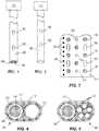
- components of a neuromodulation transfection system 100include a waveguide 160 ( FIG. 1 ), a fluidic channel 150 ( FIG. 2 ), and a neural interface array 110, which can be combined a multiple ways to produce embodiments of the neuromodulation transfection system 100, for example as shown in FIGS. 4 and 5 .
- the neural interface array 110which can be inserted in or around tissue, includes one or more electrodes including a neurosensing electrode 120, a neurostimulation electrode 130, and/or an electroporation electrode 140.
- the fluidic channel 150can be coupled to the neural interface array 110 and configured to deliver a biologic agent to target tissue.
- the waveguide 160can be coupled to an optical light source and the neural interface array 110 and configured to optically stimulate selected tissue. Additionally, each of electrodes may be used for multiple purposes, including neurosensing, neurostimulation, and electroporation. Sensing and stimulating electrodes may in some embodiments have similar properties, but in other embodiments properties may differ depending on design requirements. Sensing electrodes with a small geometric area are generally suitable for small spatial volume sensing, whereas sensing electrodes having a larger geometric area are suitable for large volume (beyond the single cellular domain) sensing and lower power consumption during stimulation.
- Electroporationalso known as electropermeabilization
- electropermeabilizationin which an externally applied electric field increases the permeability of a cell membrane, may be performed to facilitate delivery of a vector into cells and subsequent expression of light-sensitive ion channels.
- the electroporation electrodes 140may be used to facilitate introduction of a vector into neurons.
- the neuromodulation transfection system 100is multi-functional in that it can deliver biologic agents such as light-sensitive opsins and/or therapeutic or other bioactive agents to a targeted tissue region, selectively create electric fields to achieve effective electroporation in the targeted tissue region, selectively optically stimulate particular regions in the targeted tissue region, and sense neural activity in the targeted tissue region.
- the neuromodulation transfection system 100may be implanted in a particular tissue location in a single surgical procedure, which ensures accurate spatial co-localization of the biologic agents using the fluidic channel 150, the waveguide 160 for optical stimulation, the neurosensing electrodes 120, neurostimulation electrodes 130, electroporation electrodes 140, and reduces the number of separate surgeries and implants that must be endured by the patient or other subject.
- the neuromodulation transfection system 100is implantable in brain tissue or over a surface in the brain or other neural surface (e.g. spinal cord or peripheral nerves), but may alternatively be implantable in or wrapped around other suitable tissue (e.g. muscle or heart). Implantation of the neuromodulation transfection system may in various embodiments be partial or complete; in either case, implantation is performed in a manner that provides access for delivery of fluids as well as electrical and optical communications as needed. In some embodiments the neuromodulation transfection system can be a completely implanted and self contained unit.
- the neural interface array 110functions to provide a medium for interaction with surrounding tissue.
- the neural interface array 110includes a plurality of electrodes, which includes an array of neurosensing electrodes 120 for recording electrical signals, and/or an array of electroporation electrodes 140 that emit an electrical field to stimulate electroporation of targeted cells.
- the neural interface array 110may further include an array of neurostimulation electrodes 130 that electrically stimulate selected tissue regions, such as to elicit neural signals.
- the electrode sitesmay be individually and independently controllable, but at least a portion may alternatively be functionally grouped together, such as to form a selectively-controllable composite macroelectrode from a group of individual microelectrodes.
- the electroporation electrodes 140may be selectively operated in a pattern to create an electrical field that induces molecular movement and/or electropermeabilization along a desired pathway in a targeted region of tissue.
- the electroporation electrodes 140may be coupled to an external voltage driver that controls the electric field emitted by the electroporation electrodes 140.
- the neural interface array 110may be wrapped around an elongated carrier, such as a cylindrical or elliptical carrier as shown in US 2011/0093052 (hereinafter referred to as the '052 publication).
- the neural interface array 110may be configured to wrap around tissue, such as the spinal cord.
- some or all of the electrode sitesmay be ring electrodes, or circular or elliptical electrode sites distributed longitudinally along and/or circumferentially around the carrier.
- the neural interface arrayis planar (e.g.
- the electrode sitesmay be distributed along a face and/or edge of the probe, depending on the particular application of the system, as shown in U.S. Patent Application number 2011/0112591 (hereinafter referred to as the '591 publication).
- the electrode sitesmay be distributed on the neural interface array 110 in other suitable arrangements.
- the carrier and/or neural interface array 110itself may define a sharpened distal point to aid insertion into tissue (see, e.g., FIG. 7 ).
- the neural interface array 110may further define a plurality of apertures that may be one or more variations.
- a fluidic aperture 152functions as a fluid delivery port that allows passage of fluid from the fluidic channel 150 which is coupled to the neural interface array 110.
- an optical aperture 162is a hole or window of optically diffusive material that functions as an optical port that allows passage of optical light from an optical light source or waveguide 160 coupled adjacent to (e.g. layered behind) the neural interface array 110.
- the optical portmay be accompanied with light-directing elements that direct light from the optical light source or waveguide 160, such as the ports and light-directing elements described in the '591 publication.
- the fluidic aperture 152may include microvalves or other gating mechanisms to help regulate the passage of fluid through the fluid delivery port.
- the optical aperture 162may include micromirrors or other reflective or scattering mechanisms to help regulate the passage of light through the optical delivery port.
- the neural interface array 110is flexible, but in other embodiments may alternatively be rigid or semi-rigid.
- the neural interface array 110in various embodiments is a thin-film array fabricated on a wafer, a glass substrate as large as the device, or on a large rolled polymer.
- Common thin-film techniquessuch as used in semiconductor, microelectromechanical system (MEMS), flat panel technology, or roll-to-roll manufacturing may be used to create the neural interface array with standard deposition, photolithography, laser ablation, and etching techniques.
- Common substrate materialsinclude SU-8, polyimide, parylene, silicone, etc. and/or other suitable materials.
- a thin-film neural interface array 110may be formed by micromachining and/or other microfabrication techniques, such as semiconductor manufacturing processes that are known and readily understood by one ordinarily skilled in the art.
- a thin-film neural interface array 110includes a plurality of conductive layers deposited on a substrate and patterned to form the neurosensing electrodes 120, neurostimulation electrodes 130, and/or electroporation electrodes 140, using materials such as gold, platinum, iridium, titanium nitride, PEDOT, or other suitable conductive materials.
- the conductive layersmay be additionally protected from the in vivo environment by the deposition and patterning of thin layer(s) of dielectric materials such as silicon carbide, silicon dioxide, and/or diamond at appropriate temperatures.
- a thin-film neural interface array 110may further include insulating layers and conductive traces or interconnects that couple to the electrode sites and transmit signals to and from external instrumentation and the electrode sites, as disclosed in the '052 publication.
- the specific structure and formation of the electrode sitesmay depend on the particular application to which the neuromodulation transfection system 100 is applied. By having components made using thin-film or MEMS methods, one can readily combine the optical, fluidic, and electrical components of the neuromodulation transfection system for various applications and various subject anatomy by changing as few as one photolithographic step in the entire manufacturing process.
- the fluidic channel 150 of the neuromodulation transfection system 100functions to deliver a biologic agent or bioactive agent to target tissue, and may further function as a carrier that provides structural support for the system.
- the fluidic channel 150in some embodiments is coupled to a fluid reservoir 154, such as a pump or other source, internal or external to the body, for active release into tissue.
- the fluid delivered by the fluidic channel 150can contain a biologic or bioactive agent such as light-sensitive opsins (either as proteins or nucleotides encoding for the proteins, which may be packaged into vectors), drugs or other therapeutic bioactive agents, and/or other suitable fluid or other substance.
- cooperation between the fluidic channel 150 and the electroporation electrodes 140facilitates transfection of neurons or other cells in order to introduce nucleic acids into the selected cells to enable the use of optogenetic techniques.
- the system 100may include a single fluidic channel 150 for delivery of multiple kinds of agents, or may include multiple fluidic channels 150 ( FIG. 5 ), for example to provide a distinct fluidic channel 150 for each of multiple kinds of biologic or bioactive agent.
- the fluidic channel 150in some embodiments is coupled to the neural interface array 110, such as a separate structure fastened to the neural interface array 110 or a channel defined by the neural interface array 110.
- the fluidic channel 150may be implemented using tubing made of a biocompatible metal and/or polymer, or other suitable material. As shown in FIG.
- the fluidic channel 150may define one or more fluidic apertures 152 through which the carried fluid is delivered to surrounding target tissue, although in some embodiments the fluid may additionally and/or alternatively exit the fluidic channel 150 at the distal end of the lumen of the channel 150.
- the fluidic apertures 152may be specifically designed for particular types or regions of tissue, such as regions of the brain, spinal cord, peripheral nerves, or muscle.
- the fluidic apertures 152 of the fluidic channel 150may be aligned with fluidic ports 153 on the neural interface array 110.
- the fluidic ports 153 of the neural interface array 110 and the fluidic apertures on the fluidic channel 150may include microvalves or other gating mechanisms to help regulate the passage of fluid along the fluidic channel 150 and/or through the fluidic apertures 152.
- the waveguide 160 of the neuromodulation transfection system 100functions to optically stimulate selected tissue.
- the waveguide 160is coupled to an optical light source 168 such as a light-emitting diode (LED), a laser diode, or other suitable laser or light source, such that the waveguide 160 carries and/or redirects light from the optical light source.
- the waveguide 160may be coupled to an external optical light source located outside the body.
- localized light sources 168e.g. LEDs
- the optical light sourcemay have selectively adjustable parameters, such as duration, intensity, and wavelength.
- the waveguide 160may further function as a carrier or other structure for providing support for the system 100.
- the waveguide 160 in one embodimentis an optical fiber, which may be a commercially-available optical fiber or an optical fiber that is customized to be specific to a particular application (e.g. use in a brain region).
- the waveguide 160may include other suitable optical waveguide materials.
- the waveguide 160may be a thin-film structure made of a light-propagating material such as silicon oxynitride (SiO x N y ), SiO 2 , silica, S 3 N 4 , SU-8, Cytop, or other suitable material, formed by one or more of several suitable fabrication processes including: micro-optoelectro-mechanical systems (MOEMS), photolithography, microembossing, thermal nanoimprint lithography (NIL), combined nanoimprinting and photolithography (CNP), and/or other suitable fabrication process.
- the waveguide 160may include a refractor, reflector, lens, scattering element, or other light-directing elements that direct light from the optical light source.
- the waveguide 160may be similar to that described in the '591 publication, but may be other suitable kinds of optical light propagators.
- the waveguide 160may include an inner core 164 and a cladding layer 166 over the core 164, such that the core 164 and cladding layer 166 facilitate internal reflection along the waveguide 160.
- the cladding layer 166may be etched to include one or more apertures 162 or diffusion ports through which the carried light from the optical light source may pass.
- the apertures 162 or diffusion ports of the waveguide 160may be aligned with optical ports 163 of the neural interface array 110.
- the system 100includes an elongated probe in which the neural interface array 110 is wrapped at least partially around the fluidic channel 150 and/or waveguide 160, which function as a carrier that provides structural support for the system 100.
- the fluidic channel 150 and/or waveguide 160may include a sharpened distal point to aid insertion of the system 100 into tissue.
- the neural interface array 110may include fluid delivery and/or optical ports that align with apertures of the fluidic channel and/or diffusion ports of the waveguide 160 to allow fluid and optical light pass through the array to surrounding selected tissues.
- At least some of the electroporation 140, neurostimulation 130, and/or neurosensing 120 electrodesare in various embodiments proximate to the apertures of the neural interface array 110, such that some electrodes are approximately co-located with the apertures to interact with the same region of tissue.
- the neurosensing electrodes 120, neurostimulation electrodes 130, electroporation electrodes 140, emission locations of bioactive agents and/or optical stimulationare, in many embodiments, adjacent to one another such that the same tissue regions (targeted cells) may be electropermeabilized by the electroporation electrodes 140, receive bioactive agents, be optically stimulated through the optical ports, electrically stimulated by neurostimulation electrodes 130, and/or sensed by neurosensing electrodes 120 without requiring repositioning of the implanted system 100 or replacement of the implanted system 100 with another device.
- the electroporation electrodes 140may be interspersed with the fluidic delivery ports and optical ports of the neural interface array 110.
- the neural interface array 110may be coupled to the waveguide 160 and fluidic channel 150 by wrapping the thin-film neural interface array 110 around the waveguide 160 and fluidic channel 150, injecting a polymer 180 such as silicone to fill the spaces between the neural interface array 110, waveguide 160, and fluidic channel 150, and cured to seal the assembled neuromodulation transfection system 100 ( FIGS. 4 and 5 ).
- the system 100may be manufactured and assembled in other suitable ways.
- the system 100includes a planar probe 170 having a first side (which for convenience may be referred to as the "front" face) and a second side (which for convenience may be referred to as the "back" face).
- a carriersuch as the fluidic channel 150, waveguide 160 and/or other elongated structure
- the fluidic channel 150 and waveguide 160may be concentrically or telescopically engaged, such as the waveguide 160 passing within the lumen of the fluidic channel 150 (e.g. as shown in FIGS. 6-8 ), thereby creating an annular space between the waveguide 160 and the wall of the fluidic channel 150 through which fluid may pass.
- the fluidic channel 150 and waveguide 160may be adjacent to one another and longitudinally aligned with the probe 170, coupled to the front face and/or back face of the probe 170 ( FIG. 10 ).
- the sites of the neurostimulation 120, neurosensing 130, and/or electroporation 140 electrodesmay be arranged along the centerline or edge of one or both of the faces of the probe 170 (e.g. FIG. 11 ), but may be distributed in other suitable arrangements.
- the electrodes and locations of bioactive agents and/or optical simulationmay be, in many embodiments, adjacent to one another such that they facilitate interaction with the same tissue regions. Thus, as shown in FIG.
- delivery of light and fluid and electrical stimulation, sensing, and electroporationoccur in approximately the same region 190 of tissue.
- the electroporation electrodes 140may also be placed both near to and far from the fluidic port 152 and thereby be used to selectively transfect tissue in discrete anatomical locations without changing the position of the fluidic port itself. Creating discrete electroporation regions by controlling electrode placement allows specific neural circuits to be affected with a high degree of control. Identification of the neural circuits appropriate for electroporation may be performed using neurosensing electrodes 120 or using neurostimulation 130 or electroporation electrodes 140 in sensing mode.
- the system 100may include a substantially planar neural interface array 110', such as for covering a tissue surface (e.g., brain or muscle).
- the substantially planar neural interface array 110'may additionally and/or alternatively be configured to wrap around tissue, such as the spinal cord.
- the fluidic channel 150may be coupled to the surface of the substantially planar neural interface array 110', and/or be embedded within the substrate of the substantially planar neural interface array 110'. As shown in FIG.
- the substantially planar neural interface array 110'includes distributed sites for neurosensing 120, neurostimulation 130, and/or electroporation 140 electrodes, and one or more optical ports 163 from which light emanates from one or more light sources (e.g., LEDs or light conducted through a waveguide 160).
- the substrate of the substantially planar neural interface array 110'may include one or more fluidic apertures 152 that allow for release of the bioactive agent from the system 100.
- the electrodes and locations of bioactive agents and/or optical stimulationmay be adjacent to one another to facilitate interaction with the same tissue regions.
- each type of electrode, optical light emission, and bioactive agent emissionmay be interspersed and distributed in an approximately regular pattern so that delivery of agents, cell transfection, light-based activation of ion channels, electrical stimulation, and electrical sensing may be performed in the same discrete location(s).
- the system 100may include a variant of the substantially planar neural interface array 110' probe disclosed above.
- the neural interface array 110" of FIGS. 10-12apertures pass between the back and front faces, with the electrode sites on the front face of the probe and the fluidic channel 150 and waveguide 160 coupled to the back face of the probe.
- the fluidic channel 150 and waveguide 160may be longitudinally aligned with and adjacent to one another and with the probe such that at least some of the fluidic apertures 152 of the fluidic channel 150 and apertures 162 of the waveguide 160 are approximately aligned with the fluidic ports 153 and optical ports 163 of the probe to allow fluid and light to pass through the front side of the probe ( FIG. 10 ).
- Some of the apertures 152, 162 of the fluidic channel 150 and waveguide 160may face away from the probe such that fluid and light may pass into tissue in another direction, such as away from the front face of the probe ( FIG. 10 ).
- the system 100may include the neural interface array 110", fluidic channel 150, optical source, and waveguide 160 coupled together in various suitable arrangements in which their relative positions enable approximate co-localization of their respective interactions with tissue. Further, in certain embodiments each of the neural interface array 110", fluidic channel 150, optical source, and waveguide 160 are modular and arrangeable in custom relative positions to suit particular applications.
- the neuromodulation transfection system 100is part of a neural interface system 1000, which may include an electrical subsystem 1100, an optical subsystem 1200, a fluidic subsystem 1300, and a controller 2000.
- the electrical subsystem 1100functions to operate with the neural interface array 110, for example when the neuromodulation transfection system 100 is implanted into a subject 1500 ( FIG. 13 ).
- the subject 1500may include any number of animals into which the neuromodulation transfection system 100 may be implanted and with which the neural interface system 1000 may be employed, including without limitation rodents (e.g. rats, mice, rabbits, etc.) and primates (e.g. humans, monkeys, etc.).
- the controller 2000may control the electrical subsystem 1100, the optical subsystem 1200, and/or the fluidic subsystem 1300 to carry out the functions of the neural interface system 1000 such as those disclosed herein.
- the electrical subsystem 1100, optical subsystem 1200, fluidic subsystem 1300, and controller 2000may be integrated into a single unit or may be separate units, and each may be external to the subject 1500 or may be part of an implanted device.
- Each of the electrical subsystem 1100, optical subsystem 1200, fluidic subsystem 1300, and controller 2000may include a processor, memory, storage, input/output mechanisms, and communication mechanisms, including capabilities for wired and/or wireless communications within the components of the system 1000 and between the system 1000 and external computers and networks.
- the electrical subsystem 1100includes at least one of several variations of suitable electronic subsystems to operate with the neural interface array 110 or combinations thereof.
- the electrical subsystem 1100may be a printed circuit board with or without onboard integrated circuits and/or on-chip circuitry for signal conditioning and/or stimulus generation, an Application Specific Integrated Circuit (ASIC), a multiplexer chip, a buffer amplifier, an electronics interface, a pulse generator (which produces signals such as a highfrequency, pulsed electric current, and which in certain embodiments may be implantable), a power supply (which in various embodiments can include an implantable rechargeable battery), integrated electronics for signal processing of the input (recorded) or output (stimulation) signals (either of which may be processed in real time), other suitable electrical subsystem, or combinations thereof, as disclosed in the '052 publication.
- ASICApplication Specific Integrated Circuit
- ASICApplication Specific Integrated Circuit
- multiplexer chipwhich produces signals such as a highfrequency, pulsed electric current, and which in certain embodiments may be implantable
- the optical subsystem 1200includes power and control units to control the light source 168 in order to generate light pulses of suitable wavelength, duration, intensity, and pulse shape.
- the light source 168(either directly or via the waveguide 160) functions to illuminate surrounding tissue and stimulating targeted tissue in a manner where the light is parallel, perpendicular, or at other angles relative to the electrodes.
- the fluidic subsystem 1300includes power and control units as well as provisions for storage (e.g. a tank, cartridge, or other reservoir) and delivery (e.g. one of a number of pumping mechanisms) of one or more fluids through one or multiple fluidic channels 150, including provisions for controlling the rate, volume, and timing of fluid delivery.
- provisions for storagee.g. a tank, cartridge, or other reservoir
- deliverye.g. one of a number of pumping mechanisms
- the inventionprovides, among other things, a neuromodulation transfection system.
- the present applicationdiscloses a neuromodulation transfection system that combines multiple functions such as those disclosed herein in a form that includes highly adaptable positioning of the various components to optimize the system performance in a specific subject or application.
- Various features and advantages of the inventionare set forth in the following claims.
Landscapes
- Health & Medical Sciences (AREA)
- Life Sciences & Earth Sciences (AREA)
- Engineering & Computer Science (AREA)
- Biomedical Technology (AREA)
- Veterinary Medicine (AREA)
- Animal Behavior & Ethology (AREA)
- General Health & Medical Sciences (AREA)
- Public Health (AREA)
- Nuclear Medicine, Radiotherapy & Molecular Imaging (AREA)
- Radiology & Medical Imaging (AREA)
- Biophysics (AREA)
- Pathology (AREA)
- Neurosurgery (AREA)
- Heart & Thoracic Surgery (AREA)
- Physics & Mathematics (AREA)
- Neurology (AREA)
- Orthopedic Medicine & Surgery (AREA)
- Cardiology (AREA)
- Medical Informatics (AREA)
- Molecular Biology (AREA)
- Surgery (AREA)
- Optics & Photonics (AREA)
- Apparatus Associated With Microorganisms And Enzymes (AREA)
Description
- This application claims the benefit of
US Provisional Application No. 61/511,371 filed July 25, 2011 - The present invention relates to the neural device field, and more specifically to a new and useful neuromodulation transfection system in the neural device field.
- Various research and clinical neuroscience applications may involve a combination of different techniques for perturbing neural circuits and measuring the circuit's response. Stimulation may be electrical such as with conductive electrode sites, or may be optical such as with optogenetic tools. Such neurostimulation is typically sensed and/or recorded with electrical neurosensing. In particular, optogenetics is a developing technique that uses light-sensitive ion channels for optical stimulation of neural tissue, which allows experimenters or medical practitioners to selectively excite and/or silence particular neural channels with high precision. To create such light sensitive ion channels, the user performs a surgery in which an opsin such as ChR2 or Halorhodospin (e.g. delivered in the form of a protein or as a nucleotide for example using a viral vector) is introduced into target tissue, generally with cell-type specificity.
DocumentUS 2010/211,172 A1 relates to implantable devices for communicating with biological tissue and methods and systems for using the devices. For example, the devices are implanted in a subject and used to communicate with regenerated neural tissue.
DocumentUS 2009/292,325 A1 relates to a hybrid bioelectrical interface (HBI) device that can be an implantable device comprising an abiotic component operable to transmit charge via electrons or ions; a biological component interfacing with the neural tissue, the biological component being sourced from biologic, biologically-derived, or bio-functionalized material; and a conjugated polymer component that together provide a means to chronically interface living neural tissue with electronic devices for extended durations (e.g. greater than 10 years).
In some embodiments, conjugated polymers provide a functional electrical interface for charge transfer and signal transduction between the nervous system and an electronic device (e.g. robotic prosthetic limb, retinal implant, microchip).
DocumentUS 2011/144,566 A1 relates to systems, devices, methods, and compositions described for providing an actively-controllable disinfecting implantable device configured to, for example, treat or prevent an infection in a biological subject. - To optically stimulate or inhibit the neurons containing light-sensitive ion channels, an additional surgery is required to introduce an optical stimulator, electrical stimulator, and/or neurosensing components. In other words, the combined use of all these conventional neuroscience techniques requires multiple separate surgeries and/or implants, and every additional procedure or implant increases the difficulty of spatially co-locating the biologic agents, optical light source, neurosensing components, and other components such as drug delivery devices for therapeutic agents. Furthermore, performing multiple surgical procedures may risk creating complications for a patient or other subject.
- Thus, there is a need in the neural device field to create a new and useful neuromodulation transfection system.
- In one embodiment, the invention provides a neural interface array comprising an optical waveguide having one or more optical apertures; a thin film electrode array associated with the optical waveguide, the thin film electrode array comprising a plurality of electrodes; one or more optical ports and one or more fluidic ports; and a fluid delivery channel attached to at least one of the optical waveguide and the thin film electrode array having one or more fluidic apertures; wherein the optical waveguide, the fluid delivery channel, and the thin film electrode array are combined such that the one or more optical apertures are optically coupled with the one or more optical ports, and the one or more fluidic apertures are fluidically coupled with the one or more fluidic ports.
- Disclosed is also a method for optical stimulation using an implanted neural interface array. The method includes steps of providing a neural interface array at an implantation site in a subject, the neural interface array having an optical waveguide, a thin film electrode array associated with the optical waveguide, the electrode array including a plurality of electrodes and a fluid delivery channel associated with the optical waveguide; delivering fluid to the implantation site using the fluid delivery channel; optically stimulating using the optical waveguide; and sensing an electrical signal using one of the plurality of electrodes.
- In another embodiment, the invention provides a neural interface system configured for active fluid delivery. The system includes a neural interface array including an optical waveguide, a thin film electrode array associated with the optical waveguide, the electrode array comprising a plurality of electrodes, and a fluid delivery channel attached to the optical waveguide. The system also includes an electrical subsystem in communication with the electrode array; an optical subsystem in communication with the optical waveguide; and a fluidic subsystem in communication with the fluid delivery channel.
- Other aspects of the invention will become apparent by consideration of the detailed description and accompanying drawings.
FIG. 1 shows a perspective view of an embodiment of a waveguide of a neuromodulation transfection system;FIG. 2 shows a perspective view of an embodiment of a fluidic channel of a neuromodulation transfection system;FIG. 3 shows diagram of an embodiment of a neural interface array of a neuromodulation transfection system;FIG. 4 is a cross-sectional view of an embodiment of a neuromodulation transfection system;FIG. 5 is a cross-sectional view of another embodiment of a neuromodulation transfection system;FIG. 6 is a cross-sectional view of another embodiment of a neuromodulation transfection system;FIG. 7 is a perspective view of the neuromodulation transfection system ofFIG. 6 ;FIG. 8 is a side view of the neuromodulation transfection system ofFIG. 6 ;FIG. 9 is a schematic of another embodiment of a neuromodulation transfection system; andFIG. 10 is a cross-sectional view of another embodiment of a neuromodulation transfection system;FIG. 11 is a front view of another embodiment of a neuromodulation transfection system;FIG. 12 is a side view of another embodiment of a neuromodulation transfection system.FIG. 13 shows an embodiment of a system for use with embodiments of the disclosed neuromodulation transfection system.- Before embodiments of the invention are explained in detail, it is to be understood that the invention is not limited in its application to the details of construction and the arrangement of components set forth in the following description or illustrated in the following drawings. The invention is capable of other embodiments and of being practiced or of being carried out in various ways.
- As shown in
FIGS. 1-3 , components of aneuromodulation transfection system 100 according to various embodiments include a waveguide 160 (FIG. 1 ), a fluidic channel 150 (FIG. 2 ), and aneural interface array 110, which can be combined a multiple ways to produce embodiments of theneuromodulation transfection system 100, for example as shown inFIGS. 4 and 5 . Theneural interface array 110, which can be inserted in or around tissue, includes one or more electrodes including aneurosensing electrode 120, aneurostimulation electrode 130, and/or anelectroporation electrode 140. Thefluidic channel 150 can be coupled to theneural interface array 110 and configured to deliver a biologic agent to target tissue. Thewaveguide 160 can be coupled to an optical light source and theneural interface array 110 and configured to optically stimulate selected tissue. Additionally, each of electrodes may be used for multiple purposes, including neurosensing, neurostimulation, and electroporation. Sensing and stimulating electrodes may in some embodiments have similar properties, but in other embodiments properties may differ depending on design requirements. Sensing electrodes with a small geometric area are generally suitable for small spatial volume sensing, whereas sensing electrodes having a larger geometric area are suitable for large volume (beyond the single cellular domain) sensing and lower power consumption during stimulation. - Electroporation (also known as electropermeabilization), in which an externally applied electric field increases the permeability of a cell membrane, may be performed to facilitate delivery of a vector into cells and subsequent expression of light-sensitive ion channels. Thus, in those embodiments in which the
neural interface array 110 includeselectroporation electrodes 140, theelectroporation electrodes 140 may be used to facilitate introduction of a vector into neurons. - The
neuromodulation transfection system 100 is multi-functional in that it can deliver biologic agents such as light-sensitive opsins and/or therapeutic or other bioactive agents to a targeted tissue region, selectively create electric fields to achieve effective electroporation in the targeted tissue region, selectively optically stimulate particular regions in the targeted tissue region, and sense neural activity in the targeted tissue region. Theneuromodulation transfection system 100 may be implanted in a particular tissue location in a single surgical procedure, which ensures accurate spatial co-localization of the biologic agents using thefluidic channel 150, thewaveguide 160 for optical stimulation, theneurosensing electrodes 120,neurostimulation electrodes 130,electroporation electrodes 140, and reduces the number of separate surgeries and implants that must be endured by the patient or other subject. In some embodiments, theneuromodulation transfection system 100 is implantable in brain tissue or over a surface in the brain or other neural surface (e.g. spinal cord or peripheral nerves), but may alternatively be implantable in or wrapped around other suitable tissue (e.g. muscle or heart). Implantation of the neuromodulation transfection system may in various embodiments be partial or complete; in either case, implantation is performed in a manner that provides access for delivery of fluids as well as electrical and optical communications as needed. In some embodiments the neuromodulation transfection system can be a completely implanted and self contained unit. - The
neural interface array 110 functions to provide a medium for interaction with surrounding tissue. As noted above, theneural interface array 110 includes a plurality of electrodes, which includes an array ofneurosensing electrodes 120 for recording electrical signals, and/or an array ofelectroporation electrodes 140 that emit an electrical field to stimulate electroporation of targeted cells. Theneural interface array 110 may further include an array ofneurostimulation electrodes 130 that electrically stimulate selected tissue regions, such as to elicit neural signals. Within each electrode array, the electrode sites may be individually and independently controllable, but at least a portion may alternatively be functionally grouped together, such as to form a selectively-controllable composite macroelectrode from a group of individual microelectrodes. Theelectroporation electrodes 140 may be selectively operated in a pattern to create an electrical field that induces molecular movement and/or electropermeabilization along a desired pathway in a targeted region of tissue. In particular, theelectroporation electrodes 140 may be coupled to an external voltage driver that controls the electric field emitted by theelectroporation electrodes 140. - In a first variation, the
neural interface array 110 may be wrapped around an elongated carrier, such as a cylindrical or elliptical carrier as shown inUS 2011/0093052 (hereinafter referred to as the '052 publication). In a second variation, theneural interface array 110 may be configured to wrap around tissue, such as the spinal cord. In these variations, some or all of the electrode sites may be ring electrodes, or circular or elliptical electrode sites distributed longitudinally along and/or circumferentially around the carrier. In a third variation, the neural interface array is planar (e.g. coupled to a planar carrier or formed as a sheet) and the electrode sites may be distributed along a face and/or edge of the probe, depending on the particular application of the system, as shown inU.S. Patent Application number 2011/0112591 (hereinafter referred to as the '591 publication). However, the electrode sites may be distributed on theneural interface array 110 in other suitable arrangements. In each of these variations, the carrier and/orneural interface array 110 itself may define a sharpened distal point to aid insertion into tissue (see, e.g.,FIG. 7 ). - As shown in
FIG. 3 , theneural interface array 110 may further define a plurality of apertures that may be one or more variations. In one embodiment, afluidic aperture 152 functions as a fluid delivery port that allows passage of fluid from thefluidic channel 150 which is coupled to theneural interface array 110. In another embodiment, anoptical aperture 162 is a hole or window of optically diffusive material that functions as an optical port that allows passage of optical light from an optical light source orwaveguide 160 coupled adjacent to (e.g. layered behind) theneural interface array 110. The optical port may be accompanied with light-directing elements that direct light from the optical light source orwaveguide 160, such as the ports and light-directing elements described in the '591 publication. In either of these embodiments, thefluidic aperture 152 may include microvalves or other gating mechanisms to help regulate the passage of fluid through the fluid delivery port. Similarly, theoptical aperture 162 may include micromirrors or other reflective or scattering mechanisms to help regulate the passage of light through the optical delivery port. - In some embodiments the
neural interface array 110 is flexible, but in other embodiments may alternatively be rigid or semi-rigid. Theneural interface array 110 in various embodiments is a thin-film array fabricated on a wafer, a glass substrate as large as the device, or on a large rolled polymer. Common thin-film techniques, such as used in semiconductor, microelectromechanical system (MEMS), flat panel technology, or roll-to-roll manufacturing may be used to create the neural interface array with standard deposition, photolithography, laser ablation, and etching techniques. Common substrate materials include SU-8, polyimide, parylene, silicone, etc. and/or other suitable materials. In particular, theneural interface array 110 may be formed by micromachining and/or other microfabrication techniques, such as semiconductor manufacturing processes that are known and readily understood by one ordinarily skilled in the art. In one embodiment, a thin-filmneural interface array 110 includes a plurality of conductive layers deposited on a substrate and patterned to form theneurosensing electrodes 120,neurostimulation electrodes 130, and/orelectroporation electrodes 140, using materials such as gold, platinum, iridium, titanium nitride, PEDOT, or other suitable conductive materials. The conductive layers may be additionally protected from thein vivo environment by the deposition and patterning of thin layer(s) of dielectric materials such as silicon carbide, silicon dioxide, and/or diamond at appropriate temperatures. Furthermore, the apertures (where an aperture may also be called a via) functioning as optical or fluidic ports may be formed through patterned etching or other suitable microfabrication processes. In various embodiments, a thin-filmneural interface array 110 may further include insulating layers and conductive traces or interconnects that couple to the electrode sites and transmit signals to and from external instrumentation and the electrode sites, as disclosed in the '052 publication. However, the specific structure and formation of the electrode sites may depend on the particular application to which theneuromodulation transfection system 100 is applied. By having components made using thin-film or MEMS methods, one can readily combine the optical, fluidic, and electrical components of the neuromodulation transfection system for various applications and various subject anatomy by changing as few as one photolithographic step in the entire manufacturing process. - The
fluidic channel 150 of theneuromodulation transfection system 100 functions to deliver a biologic agent or bioactive agent to target tissue, and may further function as a carrier that provides structural support for the system. Thefluidic channel 150 in some embodiments is coupled to afluid reservoir 154, such as a pump or other source, internal or external to the body, for active release into tissue. In various embodiments, the fluid delivered by thefluidic channel 150 can contain a biologic or bioactive agent such as light-sensitive opsins (either as proteins or nucleotides encoding for the proteins, which may be packaged into vectors), drugs or other therapeutic bioactive agents, and/or other suitable fluid or other substance. As noted above, cooperation between thefluidic channel 150 and theelectroporation electrodes 140 facilitates transfection of neurons or other cells in order to introduce nucleic acids into the selected cells to enable the use of optogenetic techniques. - In various embodiments, the
system 100 may include a singlefluidic channel 150 for delivery of multiple kinds of agents, or may include multiple fluidic channels 150 (FIG. 5 ), for example to provide a distinctfluidic channel 150 for each of multiple kinds of biologic or bioactive agent. Thefluidic channel 150 in some embodiments is coupled to theneural interface array 110, such as a separate structure fastened to theneural interface array 110 or a channel defined by theneural interface array 110. Thefluidic channel 150 may be implemented using tubing made of a biocompatible metal and/or polymer, or other suitable material. As shown inFIG. 2 , thefluidic channel 150 may define one or morefluidic apertures 152 through which the carried fluid is delivered to surrounding target tissue, although in some embodiments the fluid may additionally and/or alternatively exit thefluidic channel 150 at the distal end of the lumen of thechannel 150. Thefluidic apertures 152 may be specifically designed for particular types or regions of tissue, such as regions of the brain, spinal cord, peripheral nerves, or muscle. Thefluidic apertures 152 of thefluidic channel 150 may be aligned withfluidic ports 153 on theneural interface array 110. Thefluidic ports 153 of theneural interface array 110 and the fluidic apertures on thefluidic channel 150 may include microvalves or other gating mechanisms to help regulate the passage of fluid along thefluidic channel 150 and/or through thefluidic apertures 152. - The
waveguide 160 of theneuromodulation transfection system 100 functions to optically stimulate selected tissue. Thewaveguide 160 is coupled to an opticallight source 168 such as a light-emitting diode (LED), a laser diode, or other suitable laser or light source, such that thewaveguide 160 carries and/or redirects light from the optical light source. For example, thewaveguide 160 may be coupled to an external optical light source located outside the body. In some embodiments, localized light sources 168 (e.g. LEDs) may be integrated into theneural interface array 110 in place of using awaveguide 160 to direct light from another location. The optical light source may have selectively adjustable parameters, such as duration, intensity, and wavelength. Thewaveguide 160 may further function as a carrier or other structure for providing support for thesystem 100. As shown inFIG. 1 , thewaveguide 160 in one embodiment is an optical fiber, which may be a commercially-available optical fiber or an optical fiber that is customized to be specific to a particular application (e.g. use in a brain region). Alternatively, thewaveguide 160 may include other suitable optical waveguide materials. For example, thewaveguide 160 may be a thin-film structure made of a light-propagating material such as silicon oxynitride (SiOxNy), SiO2, silica, S3N4, SU-8, Cytop, or other suitable material, formed by one or more of several suitable fabrication processes including: micro-optoelectro-mechanical systems (MOEMS), photolithography, microembossing, thermal nanoimprint lithography (NIL), combined nanoimprinting and photolithography (CNP), and/or other suitable fabrication process. Thewaveguide 160 may include a refractor, reflector, lens, scattering element, or other light-directing elements that direct light from the optical light source. Other variations of thewaveguide 160 may be similar to that described in the '591 publication, but may be other suitable kinds of optical light propagators. For example, thewaveguide 160 may include aninner core 164 and acladding layer 166 over thecore 164, such that thecore 164 andcladding layer 166 facilitate internal reflection along thewaveguide 160. Thecladding layer 166 may be etched to include one ormore apertures 162 or diffusion ports through which the carried light from the optical light source may pass. Theapertures 162 or diffusion ports of thewaveguide 160 may be aligned withoptical ports 163 of theneural interface array 110. - In one embodiment of the system, as shown in
FIG. 4 , thesystem 100 includes an elongated probe in which theneural interface array 110 is wrapped at least partially around thefluidic channel 150 and/orwaveguide 160, which function as a carrier that provides structural support for thesystem 100. As noted above, thefluidic channel 150 and/orwaveguide 160 may include a sharpened distal point to aid insertion of thesystem 100 into tissue. Further, theneural interface array 110 may include fluid delivery and/or optical ports that align with apertures of the fluidic channel and/or diffusion ports of thewaveguide 160 to allow fluid and optical light pass through the array to surrounding selected tissues. At least some of theelectroporation 140,neurostimulation 130, and/orneurosensing 120 electrodes are in various embodiments proximate to the apertures of theneural interface array 110, such that some electrodes are approximately co-located with the apertures to interact with the same region of tissue. In particular, theneurosensing electrodes 120,neurostimulation electrodes 130,electroporation electrodes 140, emission locations of bioactive agents and/or optical stimulation are, in many embodiments, adjacent to one another such that the same tissue regions (targeted cells) may be electropermeabilized by theelectroporation electrodes 140, receive bioactive agents, be optically stimulated through the optical ports, electrically stimulated byneurostimulation electrodes 130, and/or sensed byneurosensing electrodes 120 without requiring repositioning of the implantedsystem 100 or replacement of the implantedsystem 100 with another device. For example, theelectroporation electrodes 140 may be interspersed with the fluidic delivery ports and optical ports of theneural interface array 110. In embodiments such as this, theneural interface array 110 may be coupled to thewaveguide 160 andfluidic channel 150 by wrapping the thin-filmneural interface array 110 around thewaveguide 160 andfluidic channel 150, injecting apolymer 180 such as silicone to fill the spaces between theneural interface array 110,waveguide 160, andfluidic channel 150, and cured to seal the assembled neuromodulation transfection system 100 (FIGS. 4 and 5 ). However, thesystem 100 may be manufactured and assembled in other suitable ways. - In another embodiment, as shown in
FIGS. 6-8 , thesystem 100 includes a planar probe 170 having a first side (which for convenience may be referred to as the "front" face) and a second side (which for convenience may be referred to as the "back" face). A carrier (such as thefluidic channel 150,waveguide 160 and/or other elongated structure) may be coupled to the front face or back face of the probe 170 for structure support. Thefluidic channel 150 andwaveguide 160 may be concentrically or telescopically engaged, such as thewaveguide 160 passing within the lumen of the fluidic channel 150 (e.g. as shown inFIGS. 6-8 ), thereby creating an annular space between thewaveguide 160 and the wall of thefluidic channel 150 through which fluid may pass. Alternatively, thefluidic channel 150 andwaveguide 160 may be adjacent to one another and longitudinally aligned with the probe 170, coupled to the front face and/or back face of the probe 170 (FIG. 10 ). The sites of theneurostimulation 120,neurosensing 130, and/orelectroporation 140 electrodes may be arranged along the centerline or edge of one or both of the faces of the probe 170 (e.g.FIG. 11 ), but may be distributed in other suitable arrangements. As with other embodiments disclosed herein, the electrodes and locations of bioactive agents and/or optical simulation may be, in many embodiments, adjacent to one another such that they facilitate interaction with the same tissue regions. Thus, as shown inFIG. 8 , delivery of light and fluid and electrical stimulation, sensing, and electroporation occur in approximately thesame region 190 of tissue. Theelectroporation electrodes 140 may also be placed both near to and far from thefluidic port 152 and thereby be used to selectively transfect tissue in discrete anatomical locations without changing the position of the fluidic port itself. Creating discrete electroporation regions by controlling electrode placement allows specific neural circuits to be affected with a high degree of control. Identification of the neural circuits appropriate for electroporation may be performed usingneurosensing electrodes 120 or usingneurostimulation 130 orelectroporation electrodes 140 in sensing mode. - In yet another embodiment, the
system 100 may include a substantially planar neural interface array 110', such as for covering a tissue surface (e.g., brain or muscle). The substantially planar neural interface array 110' may additionally and/or alternatively be configured to wrap around tissue, such as the spinal cord. Thefluidic channel 150 may be coupled to the surface of the substantially planar neural interface array 110', and/or be embedded within the substrate of the substantially planar neural interface array 110'. As shown inFIG. 9 , in this embodiment the substantially planar neural interface array 110' includes distributed sites forneurosensing 120,neurostimulation 130, and/orelectroporation 140 electrodes, and one or moreoptical ports 163 from which light emanates from one or more light sources (e.g., LEDs or light conducted through a waveguide 160). The substrate of the substantially planar neural interface array 110' may include one or morefluidic apertures 152 that allow for release of the bioactive agent from thesystem 100. As with other embodiments disclosed herein, the electrodes and locations of bioactive agents and/or optical stimulation may be adjacent to one another to facilitate interaction with the same tissue regions. For example, each type of electrode, optical light emission, and bioactive agent emission may be interspersed and distributed in an approximately regular pattern so that delivery of agents, cell transfection, light-based activation of ion channels, electrical stimulation, and electrical sensing may be performed in the same discrete location(s). - In additional embodiments, aspects of the various disclosed embodiments may be combined. For example, as shown in
FIGS. 10-12 , thesystem 100 may include a variant of the substantially planar neural interface array 110' probe disclosed above. In theneural interface array 110" ofFIGS. 10-12 , apertures pass between the back and front faces, with the electrode sites on the front face of the probe and thefluidic channel 150 andwaveguide 160 coupled to the back face of the probe. In particular, thefluidic channel 150 andwaveguide 160 may be longitudinally aligned with and adjacent to one another and with the probe such that at least some of thefluidic apertures 152 of thefluidic channel 150 andapertures 162 of thewaveguide 160 are approximately aligned with thefluidic ports 153 andoptical ports 163 of the probe to allow fluid and light to pass through the front side of the probe (FIG. 10 ). Some of theapertures fluidic channel 150 andwaveguide 160 may face away from the probe such that fluid and light may pass into tissue in another direction, such as away from the front face of the probe (FIG. 10 ). In additional alternative embodiments, thesystem 100 may include theneural interface array 110",fluidic channel 150, optical source, andwaveguide 160 coupled together in various suitable arrangements in which their relative positions enable approximate co-localization of their respective interactions with tissue. Further, in certain embodiments each of theneural interface array 110",fluidic channel 150, optical source, andwaveguide 160 are modular and arrangeable in custom relative positions to suit particular applications. - In certain embodiments the
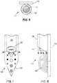
neuromodulation transfection system 100 is part of aneural interface system 1000, which may include anelectrical subsystem 1100, anoptical subsystem 1200, afluidic subsystem 1300, and acontroller 2000. Theelectrical subsystem 1100 functions to operate with theneural interface array 110, for example when theneuromodulation transfection system 100 is implanted into a subject 1500 (FIG. 13 ). The subject 1500 may include any number of animals into which theneuromodulation transfection system 100 may be implanted and with which theneural interface system 1000 may be employed, including without limitation rodents (e.g. rats, mice, rabbits, etc.) and primates (e.g. humans, monkeys, etc.). - The
controller 2000 may control theelectrical subsystem 1100, theoptical subsystem 1200, and/or thefluidic subsystem 1300 to carry out the functions of theneural interface system 1000 such as those disclosed herein. Theelectrical subsystem 1100,optical subsystem 1200,fluidic subsystem 1300, andcontroller 2000 may be integrated into a single unit or may be separate units, and each may be external to the subject 1500 or may be part of an implanted device. Each of theelectrical subsystem 1100,optical subsystem 1200,fluidic subsystem 1300, andcontroller 2000 may include a processor, memory, storage, input/output mechanisms, and communication mechanisms, including capabilities for wired and/or wireless communications within the components of thesystem 1000 and between thesystem 1000 and external computers and networks. - The
electrical subsystem 1100 includes at least one of several variations of suitable electronic subsystems to operate with theneural interface array 110 or combinations thereof. Theelectrical subsystem 1100 may be a printed circuit board with or without onboard integrated circuits and/or on-chip circuitry for signal conditioning and/or stimulus generation, an Application Specific Integrated Circuit (ASIC), a multiplexer chip, a buffer amplifier, an electronics interface, a pulse generator (which produces signals such as a highfrequency, pulsed electric current, and which in certain embodiments may be implantable), a power supply (which in various embodiments can include an implantable rechargeable battery), integrated electronics for signal processing of the input (recorded) or output (stimulation) signals (either of which may be processed in real time), other suitable electrical subsystem, or combinations thereof, as disclosed in the '052 publication. - The
optical subsystem 1200 includes power and control units to control thelight source 168 in order to generate light pulses of suitable wavelength, duration, intensity, and pulse shape. The light source 168 (either directly or via the waveguide 160) functions to illuminate surrounding tissue and stimulating targeted tissue in a manner where the light is parallel, perpendicular, or at other angles relative to the electrodes. - The
fluidic subsystem 1300 includes power and control units as well as provisions for storage (e.g. a tank, cartridge, or other reservoir) and delivery (e.g. one of a number of pumping mechanisms) of one or more fluids through one or multiplefluidic channels 150, including provisions for controlling the rate, volume, and timing of fluid delivery. - Thus, the invention provides, among other things, a neuromodulation transfection system. The present application discloses a neuromodulation transfection system that combines multiple functions such as those disclosed herein in a form that includes highly adaptable positioning of the various components to optimize the system performance in a specific subject or application. Various features and advantages of the invention are set forth in the following claims.
Claims (10)
- A neural interface array (110), comprising:an optical waveguide (160) having one or more optical apertures (162);a thin film electrode array associated with the optical waveguide (160), the thin film electrode array comprising a plurality of electrodes, one or more optical ports (163) and one or more fluidic ports (153); anda fluid delivery channel (150) attached to at least one of the optical waveguide (160) and the thin film electrode array having one or more fluidic apertures (152); wherein the optical waveguide (160), the fluid delivery channel (150), and the thin film electrode array are combined such that the one or more optical apertures (162) are optically coupled with the one or more optical ports (163), and the one or more fluidic apertures (152) are fluidically coupled with the one or more fluidic ports (153).
- The neural interface array (110) of claim 1, wherein the optical waveguide (160) and the fluid delivery channel (150) are adjacent to one another; preferably
wherein the thin film electrode array comprises a flexible substrate, which wraps around the optical waveguide (160) and the fluid delivery channel (150). - The neural interface array (110) of claim 1, wherein the optical waveguide (160) and fluid delivery channel (150) are concentric; preferably
wherein the fluid delivery channel (150) surrounds the optical waveguide (160). - The neural interface array (110) of claim 1, wherein the thin film electrode array comprises a flexible substrate and wherein the flexible substrate wraps around the optical waveguide (160) and the fluid delivery channel (150).
- The neural interface array of claim 1, wherein the fluid delivery channel terminates in a fluidic aperture (152), preferably
wherein at least one of the plurality of electrodes comprises an electroporation electrode (140) and wherein the electroporation electrode (140) is adjacent to the fluidic aperture (152). - The neural interface array (110) of claim 1, wherein the plurality of electrodes comprises a neurosensing electrode; and/or
wherein the plurality of electrodes comprises a neurostimulation electrode (130); and/or
said array further comprising a plurality of fluid delivery channels (150) associated with the waveguide (160). - A neural interface system configured for active fluid delivery, comprising a neural interface array (110) as claimed in claim 1.
- The system of claim 7, wherein the optical waveguide (160) and fluid delivery channel (150) are adjacent to one another; preferably
wherein the thin film electrode array comprises a flexible substrate which wraps around the optical waveguide (160) and the fluid delivery channel (150). - The system of claim 7, wherein the optical waveguide (160) and fluid delivery channel (150) are concentric; preferably
wherein the fluid delivery channel (150) surrounds the optical waveguide (160). - The system of claim 7, wherein the thin film electrode array comprises a flexible substrate and wherein the flexible substrate wraps around the optical waveguide (160) and the fluid delivery channel (150).
Applications Claiming Priority (2)
| Application Number | Priority Date | Filing Date | Title |
|---|---|---|---|
| US201161511371P | 2011-07-25 | 2011-07-25 | |
| PCT/US2012/048075WO2013016391A1 (en) | 2011-07-25 | 2012-07-25 | Neuromodulation transfection system with means for active fluid delivery and a method for its use |
Publications (2)
| Publication Number | Publication Date |
|---|---|
| EP2736406A1 EP2736406A1 (en) | 2014-06-04 |
| EP2736406B1true EP2736406B1 (en) | 2019-09-04 |
Family
ID=46614636
Family Applications (1)
| Application Number | Title | Priority Date | Filing Date |
|---|---|---|---|
| EP12743611.1AActiveEP2736406B1 (en) | 2011-07-25 | 2012-07-25 | Neuromodulation transfection system with means for active fluid delivery |
Country Status (3)
| Country | Link |
|---|---|
| US (1) | US9700736B2 (en) |
| EP (1) | EP2736406B1 (en) |
| WO (1) | WO2013016391A1 (en) |
Families Citing this family (25)
| Publication number | Priority date | Publication date | Assignee | Title |
|---|---|---|---|---|
| US9700736B2 (en) | 2011-07-25 | 2017-07-11 | Neuronexus Technologies, Inc. | Neuromodulation transfection system with active fluid delivery |
| US9782091B2 (en) | 2011-07-25 | 2017-10-10 | Neuronexus Technologies, Inc. | Opto-electrical device for artifact reduction |
| US10493297B2 (en) | 2011-07-25 | 2019-12-03 | Neuronexus Technologies, Inc. | Neuromodulation transfection system with passive fluid delivery |
| US9486641B2 (en) | 2013-03-16 | 2016-11-08 | Lawrence Livermore National Security, Llc | Incorporating an optical waveguide into a neural interface |
| USD750248S1 (en)* | 2013-04-08 | 2016-02-23 | Medtronic Bakken Research Center B.V. | Apparatus for stimulation of the nervous system |
| CN103301576A (en)* | 2013-05-27 | 2013-09-18 | 中国科学院苏州生物医学工程技术研究所 | Implantable multimodal neuromodulation electrode based on photoelectric technology and manufacturing method thereof |
| EP2808056B1 (en)* | 2013-05-29 | 2020-04-15 | Imec VZW | Optical stimulation device |
| ITTO20130603A1 (en)* | 2013-07-17 | 2015-01-18 | Fond Istituto Italiano Di Tecnologia | OPTOGENETIC INSTRUMENT FOR MULTIPLE AND INDEPENDENT ADDRESSING OF PATTERNED OPTICAL WINDOWS |
| KR102377409B1 (en)* | 2013-12-20 | 2022-03-21 | 뉴로나노 아베 | Medical device comprising an electrode and a light source |
| CN104490385A (en)* | 2014-12-12 | 2015-04-08 | 上海大学 | Needle type microelectrode array |
| CN105477780B (en)* | 2015-12-01 | 2018-11-13 | 中国科学院苏州生物医学工程技术研究所 | Implantable nerve stimulates the optoelectronic pole and its manufacturing method with record |
| US10207103B2 (en)* | 2016-07-05 | 2019-02-19 | Pacesetter, Inc. | Implantable thin film devices |
| CN106178271B (en)* | 2016-07-05 | 2019-05-24 | 上海交通大学 | The flexible nerve electrode device and preparation method thereof that LED light stimulation and electrographic recording integrate |
| CA3041999A1 (en) | 2016-10-31 | 2018-05-03 | The Alfred E. Mann Foundation For Scientific Research | Nerve cuff electrodes fabricated using over-molded lcp substrates |
| US10809513B2 (en)* | 2017-06-06 | 2020-10-20 | United Arab Emirates University | Functionalized optical lens and method of manufacturing |
| US12226626B2 (en) | 2019-07-01 | 2025-02-18 | Wavegate Corporation | Electrode and percutaneous lead and method of use |
| WO2021003496A1 (en)* | 2019-07-01 | 2021-01-07 | Wavegate Corporation | Improved surgical electrode and lead for use with implanted pulse generator and method of use |
| KR102252113B1 (en)* | 2019-09-19 | 2021-05-17 | 한국과학기술연구원 | Neural probe structure for measuring multiple fluorescence signals and manufacturing method thereof |
| AU2020371599B2 (en) | 2019-10-21 | 2025-09-04 | Incando Therapeutics Pte. Ltd. | Methods and apparatus for phototherapy |
| CA3193733A1 (en) | 2020-09-02 | 2022-03-10 | The Alfred E. Mann Foundation For Scientific Research | Electrode leads having multi-application nerve cuffs and associated systems and methods |
| US12343554B2 (en)* | 2020-09-28 | 2025-07-01 | Carnegie Mellon University | Implantable photonic platform |
| AU2022249112A1 (en) | 2021-03-30 | 2023-10-12 | The Alfred E. Mann Foundation For Scientific Research | Electrode leads having nerve cuffs and associated systems |
| EP4366818A1 (en) | 2021-07-09 | 2024-05-15 | The Alfred E. Mann Foundation for Scientific Research | Electrode leads having multi-application helical nerve cuffs and associated systems and methods |
| US12296172B2 (en) | 2022-02-01 | 2025-05-13 | The Alfred E. Mann Foundation For Scientific Research | Electrode leads having nerve contact elements with coil contacts and associated systems and methods |
| WO2024256494A1 (en)* | 2023-06-16 | 2024-12-19 | Danmarks Tekniske Universitet | Angled fiber-based neural implant for neuromodulation |
Family Cites Families (68)
| Publication number | Priority date | Publication date | Assignee | Title |
|---|---|---|---|---|
| US3628017A (en) | 1970-06-18 | 1971-12-14 | Itek Corp | Ultraviolet light-sensitive cell using a substantially chemically unchanged semiconductor electrode in an electrolyte |
| US5356630A (en) | 1989-02-22 | 1994-10-18 | Massachusetts Institute Of Technology | Delivery system for controlled release of bioactive factors |
| US20060024359A1 (en) | 1995-06-07 | 2006-02-02 | Walker Jeffrey P | Drug delivery system and method |
| US6188097B1 (en) | 1997-07-02 | 2001-02-13 | Micron Technology, Inc. | Rough electrode (high surface area) from Ti and TiN |
| US6778853B1 (en) | 1997-12-17 | 2004-08-17 | University Of South Florida | Electroporation device |
| US7171263B2 (en)* | 1999-06-04 | 2007-01-30 | Impulse Dynamics Nv | Drug delivery device |
| US7096070B1 (en)* | 2000-02-09 | 2006-08-22 | Transneuronix, Inc. | Medical implant device for electrostimulation using discrete micro-electrodes |
| US6294074B1 (en) | 2000-05-18 | 2001-09-25 | The University Of Chicago | Electrode design for corrosion monitoring using electrochemical noise measurements |
| US20020116028A1 (en)* | 2001-02-20 | 2002-08-22 | Wilson Greatbatch | MRI-compatible pacemaker with pulse carrying photonic catheter providing VOO functionality |
| US7214197B2 (en) | 2001-11-06 | 2007-05-08 | Prass Richard L | Intraoperative neurophysiological monitoring system |
| JP2003149491A (en)* | 2001-11-15 | 2003-05-21 | Furukawa Electric Co Ltd:The | Optical waveguide circuit module |
| US20030147958A1 (en) | 2002-01-29 | 2003-08-07 | Cheol-Hee Ahn | Biodegradable multi-block copolymers of poly(amino acid)s and poly(ethylene glycol) for the delivery of bioactive agents |
| WO2003107087A1 (en) | 2002-06-13 | 2003-12-24 | Nokia Corporation | Enhancement electrode configuration for electrically controlled light modulators |
| US20040111139A1 (en) | 2002-12-10 | 2004-06-10 | Mccreery Douglas B. | Apparatus and methods for differential stimulation of nerve fibers |
| US6874950B2 (en)* | 2002-12-17 | 2005-04-05 | International Business Machines Corporation | Devices and methods for side-coupling optical fibers to optoelectronic components |
| US10052497B2 (en) | 2005-07-22 | 2018-08-21 | The Board Of Trustees Of The Leland Stanford Junior University | System for optical stimulation of target cells |
| WO2008089003A2 (en) | 2007-01-09 | 2008-07-24 | The Board Of Trustees Of The Leland Stanford Junior University | System for optical stimulation of target cells |
| US9274099B2 (en) | 2005-07-22 | 2016-03-01 | The Board Of Trustees Of The Leland Stanford Junior University | Screening test drugs to identify their effects on cell membrane voltage-gated ion channel |
| US8005526B2 (en) | 2005-08-31 | 2011-08-23 | The Regents Of The University Of Michigan | Biologically integrated electrode devices |
| US8140170B2 (en)* | 2005-09-12 | 2012-03-20 | The Cleveland Clinic Foundation | Method and apparatus for renal neuromodulation |
| US8792978B2 (en)* | 2010-05-28 | 2014-07-29 | Lockheed Martin Corporation | Laser-based nerve stimulators for, E.G., hearing restoration in cochlear prostheses and method |
| US7606622B2 (en) | 2006-01-24 | 2009-10-20 | Cardiac Pacemakers, Inc. | Method and device for detecting and treating depression |
| EP2019588A4 (en) | 2006-05-04 | 2010-11-24 | Univ Wayne State | RECOVERY OF VISUAL REACTIONS BY IN VIVO ADMINISTRATION OF RHODOPSIN NUCLEIC ACIDS |
| US7955889B1 (en) | 2006-07-11 | 2011-06-07 | The Trustees Of Princeton University | Organic photosensitive cells grown on rough electrode with nano-scale morphology control |
| EP2131919A4 (en)* | 2007-04-02 | 2010-10-20 | Georgia Tech Res Inst | Implantable device for communicating with biological tissue |
| US20090210039A1 (en)* | 2007-05-09 | 2009-08-20 | Boyden Edward S | Prosthetic system for therapeutic optical activation and silencing of genetically-targeted neurons |
| US8734718B2 (en) | 2007-08-17 | 2014-05-27 | The Invention Science Fund I, Llc | Systems, devices, and methods including catheters having an actively controllable therapeutic agent delivery component |
| US9138596B2 (en)* | 2007-08-22 | 2015-09-22 | Cardiac Pacemakers, Inc. | Optical depolarization of cardiac tissue |
| US10434327B2 (en) | 2007-10-31 | 2019-10-08 | The Board Of Trustees Of The Leland Stanford Junior University | Implantable optical stimulators |
| US8562658B2 (en) | 2007-12-06 | 2013-10-22 | Technion Research & Development Foundation Limited | Method and system for optical stimulation of neurons |
| WO2009124220A2 (en) | 2008-04-02 | 2009-10-08 | St. Jude Medical, Atrial Fibrillation Division, Inc. | Photodynamic-based myocardial mapping device and method |
| EP3165534B1 (en) | 2008-04-23 | 2018-09-26 | The Board of Trustees of The Leland Stanford Junior University | Systems, methods and compositions for optical stimulation of target cells |
| US20090292325A1 (en)* | 2008-05-02 | 2009-11-26 | Cederna Paul S | Hybrid bioelectrical interface device |
| GB0816501D0 (en) | 2008-09-10 | 2008-10-15 | Imp Innovations Ltd | Photo-ionic pacemakers |
| NZ602416A (en) | 2008-11-14 | 2014-08-29 | Univ Leland Stanford Junior | Optically-based stimulation of target cells and modifications thereto |
| KR101051025B1 (en) | 2008-12-23 | 2011-07-26 | 한국과학기술연구원 | Brain stimulation and measurement apparatus and method of manufacturing the same |
| EP2240240B1 (en) | 2009-01-23 | 2014-06-25 | MED-EL Elektromedizinische Geräte GmbH | Stimulation channel conditioning |
| US8718784B2 (en) | 2010-01-14 | 2014-05-06 | Nano-Retina, Inc. | Penetrating electrodes for retinal stimulation |
| US8428740B2 (en) | 2010-08-06 | 2013-04-23 | Nano-Retina, Inc. | Retinal prosthesis techniques |
| US8442641B2 (en) | 2010-08-06 | 2013-05-14 | Nano-Retina, Inc. | Retinal prosthesis techniques |
| US20120035583A1 (en)* | 2009-03-19 | 2012-02-09 | Jehuda Peter Sepkuty | Multimode neurobiophysiology probe |
| EP2408514B1 (en) | 2009-03-20 | 2017-01-25 | Retina Implant AG | Active retinal implant |
| DE102009015389A1 (en) | 2009-03-20 | 2010-09-30 | Retina Implant Ag | Active retinal implant for eye for serving to counteract loss of vision due to degenerations of retina, has array of stimulation elements that are designed as radiation-emitting elements |
| US9089698B2 (en) | 2009-04-17 | 2015-07-28 | The Regents Of The University Of California | Method and apparatus for optogenetic treatment of blindness including retinitis pigmentosa |
| TWI511756B (en) | 2009-04-21 | 2015-12-11 | 伊穆諾萊特公司 | Pharmaceutical composition or kit for modifying a target structure which mediates or is associated with a biological activity |
| EP2278332A1 (en) | 2009-07-20 | 2011-01-26 | Fondazione Centro San Raffaele del Monte Tabor | Method for optical measuring variations of cell membrane conductance |
| US20110087126A1 (en) | 2009-10-08 | 2011-04-14 | Massachusetts Institute Of Technology | Light-Proof Electrodes |
| US8332046B2 (en) | 2009-10-16 | 2012-12-11 | Neuronexus Technologies, Inc. | Neural interface system |
| CN102686147B (en) | 2009-11-05 | 2016-01-20 | 格雷特巴奇有限公司 | waveguide neural interface device |
| WO2011057276A2 (en) | 2009-11-09 | 2011-05-12 | University Of Utah Research Foundation | Three-dimensional penetrating optical-electrical neural interface for selective stimulation and recording |
| WO2011068696A2 (en)* | 2009-11-19 | 2011-06-09 | The Regents Of The University Of Michigan | Neural probe with optical stimulation capability |
| US10001470B2 (en) | 2009-12-04 | 2018-06-19 | Sanford-Burnham Medical Research Institute | Method, system and composition for optically inducing cardiomyocyte contraction |
| ES2676274T3 (en) | 2010-03-17 | 2018-07-18 | The Board Of Trustees Of The Leland Stanford Junior University | Light sensitive molecules that allow the passage of ions |
| GB201017820D0 (en) | 2010-10-21 | 2010-12-01 | King S College London | Cells and devices |
| KR101150422B1 (en)* | 2010-10-26 | 2012-06-01 | 한국과학기술연구원 | Optical Stimulus Probe with Reflecting Surface |
| JP6276591B2 (en) | 2010-11-05 | 2018-02-07 | ザ ボード オブ トラスティーズ オブ ザ レランド スタンフォード ジュニア ユニバーシティー | Photo-activated chimeric opsin and method of use thereof |
| WO2012061744A2 (en) | 2010-11-05 | 2012-05-10 | The Board Of Trustees Of The Leland Stanford Junior University | Stabilized step function opsin proteins and methods of using the same |
| EP2635346B1 (en) | 2010-11-05 | 2017-03-29 | The Board of Trustees of the Leland Stanford Junior University | Optogenetic control of reward-related behaviors |
| US20120310140A1 (en) | 2010-12-01 | 2012-12-06 | Spinal Modulation, Inc. | Directed delivery of agents to neural anatomy |
| KR101206462B1 (en)* | 2011-01-05 | 2012-11-29 | 한국과학기술연구원 | Optical Stimulus Probe Structure with Optical transmittable Probe and Manufacturing method thereof |
| WO2012135511A1 (en)* | 2011-03-29 | 2012-10-04 | The Charles Stark Draper Laboratory, Inc. | Probe for neural recording and optical spectroscopic interrogation |
| US8986292B2 (en)* | 2011-04-13 | 2015-03-24 | St. Jude Medical, Inc. | Optical feedback RF ablator and ablator tip |
| US9801559B2 (en)* | 2011-07-25 | 2017-10-31 | Diagnostic Biochips, Inc. | Integrated optical neural probe |
| US9782091B2 (en) | 2011-07-25 | 2017-10-10 | Neuronexus Technologies, Inc. | Opto-electrical device for artifact reduction |
| US9700736B2 (en) | 2011-07-25 | 2017-07-11 | Neuronexus Technologies, Inc. | Neuromodulation transfection system with active fluid delivery |
| US10493297B2 (en) | 2011-07-25 | 2019-12-03 | Neuronexus Technologies, Inc. | Neuromodulation transfection system with passive fluid delivery |
| US9808179B2 (en)* | 2011-08-03 | 2017-11-07 | Flip Technologies Limited | Catheter and a system and a method for locating a catheter in a vessel |
| US9125573B2 (en)* | 2011-12-29 | 2015-09-08 | St. Jude Medical, Atrial Fibrillation Division, Inc. | Electrically transparent introducer sheath |
- 2012
- 2012-07-25USUS13/557,536patent/US9700736B2/ennot_activeExpired - Fee Related
- 2012-07-25EPEP12743611.1Apatent/EP2736406B1/enactiveActive
- 2012-07-25WOPCT/US2012/048075patent/WO2013016391A1/enactiveApplication Filing
Non-Patent Citations (1)
| Title |
|---|
| None* |
Also Published As
| Publication number | Publication date |
|---|---|
| US20130030352A1 (en) | 2013-01-31 |
| US9700736B2 (en) | 2017-07-11 |
| EP2736406A1 (en) | 2014-06-04 |
| WO2013016391A1 (en) | 2013-01-31 |
Similar Documents
| Publication | Publication Date | Title |
|---|---|---|
| EP2736406B1 (en) | Neuromodulation transfection system with means for active fluid delivery | |
| US10493297B2 (en) | Neuromodulation transfection system with passive fluid delivery | |
| EP3192562B1 (en) | Devices for optical stimulation of target cells using an optical transmission element | |
| US10357649B2 (en) | Neural interface system | |
| US11110290B2 (en) | Implantable device with optical lead | |
| EP3313505A1 (en) | Electroporation system for controlled localized therapeutics delivery | |
| US11497913B1 (en) | Micro-fabricated electrode arrays with flexible substrate for highly charge-efficient and selective stimulation of nerve tissue | |
| KR101917500B1 (en) | Neural electrode device comprsing neural electrode array and micro fluidic channel for deliverying drug | |
| US20230096373A1 (en) | Electrical optical medical lead | |
| KR101019464B1 (en) | Optical stimulation system | |
| C. Coffey | Optogenetics: Controlling neurons with photons |
Legal Events
| Date | Code | Title | Description |
|---|---|---|---|
| PUAI | Public reference made under article 153(3) epc to a published international application that has entered the european phase | Free format text:ORIGINAL CODE: 0009012 | |
| 17P | Request for examination filed | Effective date:20140221 | |
| AK | Designated contracting states | Kind code of ref document:A1 Designated state(s):AL AT BE BG CH CY CZ DE DK EE ES FI FR GB GR HR HU IE IS IT LI LT LU LV MC MK MT NL NO PL PT RO RS SE SI SK SM TR | |
| DAX | Request for extension of the european patent (deleted) | ||
| RAP1 | Party data changed (applicant data changed or rights of an application transferred) | Owner name:GREATBATCH LTD. | |
| RAP1 | Party data changed (applicant data changed or rights of an application transferred) | Owner name:NEURONEXUS TECHNOLOGIES, INC. | |
| RAP1 | Party data changed (applicant data changed or rights of an application transferred) | Owner name:NEURONEXUS TECHNOLOGIES, INC. | |
| STAA | Information on the status of an ep patent application or granted ep patent | Free format text:STATUS: EXAMINATION IS IN PROGRESS | |
| 17Q | First examination report despatched | Effective date:20180511 | |
| GRAP | Despatch of communication of intention to grant a patent | Free format text:ORIGINAL CODE: EPIDOSNIGR1 | |
| STAA | Information on the status of an ep patent application or granted ep patent | Free format text:STATUS: GRANT OF PATENT IS INTENDED | |
| INTG | Intention to grant announced | Effective date:20190307 | |
| RAP1 | Party data changed (applicant data changed or rights of an application transferred) | Owner name:NEURONEXUS TECHNOLOGIES, INC. | |
| GRAS | Grant fee paid | Free format text:ORIGINAL CODE: EPIDOSNIGR3 | |
| GRAA | (expected) grant | Free format text:ORIGINAL CODE: 0009210 | |
| STAA | Information on the status of an ep patent application or granted ep patent | Free format text:STATUS: THE PATENT HAS BEEN GRANTED | |
| AK | Designated contracting states | Kind code of ref document:B1 Designated state(s):AL AT BE BG CH CY CZ DE DK EE ES FI FR GB GR HR HU IE IS IT LI LT LU LV MC MK MT NL NO PL PT RO RS SE SI SK SM TR | |
| REG | Reference to a national code | Ref country code:GB Ref legal event code:FG4D | |
| REG | Reference to a national code | Ref country code:CH Ref legal event code:EP | |
| REG | Reference to a national code | Ref country code:AT Ref legal event code:REF Ref document number:1174207 Country of ref document:AT Kind code of ref document:T Effective date:20190915 | |
| REG | Reference to a national code | Ref country code:DE Ref legal event code:R096 Ref document number:602012063628 Country of ref document:DE | |
| REG | Reference to a national code | Ref country code:IE Ref legal event code:FG4D | |
| REG | Reference to a national code | Ref country code:NL Ref legal event code:MP Effective date:20190904 | |
| REG | Reference to a national code | Ref country code:LT Ref legal event code:MG4D | |
| PG25 | Lapsed in a contracting state [announced via postgrant information from national office to epo] | Ref country code:LT Free format text:LAPSE BECAUSE OF FAILURE TO SUBMIT A TRANSLATION OF THE DESCRIPTION OR TO PAY THE FEE WITHIN THE PRESCRIBED TIME-LIMIT Effective date:20190904 Ref country code:BG Free format text:LAPSE BECAUSE OF FAILURE TO SUBMIT A TRANSLATION OF THE DESCRIPTION OR TO PAY THE FEE WITHIN THE PRESCRIBED TIME-LIMIT Effective date:20191204 Ref country code:FI Free format text:LAPSE BECAUSE OF FAILURE TO SUBMIT A TRANSLATION OF THE DESCRIPTION OR TO PAY THE FEE WITHIN THE PRESCRIBED TIME-LIMIT Effective date:20190904 Ref country code:SE Free format text:LAPSE BECAUSE OF FAILURE TO SUBMIT A TRANSLATION OF THE DESCRIPTION OR TO PAY THE FEE WITHIN THE PRESCRIBED TIME-LIMIT Effective date:20190904 Ref country code:HR Free format text:LAPSE BECAUSE OF FAILURE TO SUBMIT A TRANSLATION OF THE DESCRIPTION OR TO PAY THE FEE WITHIN THE PRESCRIBED TIME-LIMIT Effective date:20190904 Ref country code:NO Free format text:LAPSE BECAUSE OF FAILURE TO SUBMIT A TRANSLATION OF THE DESCRIPTION OR TO PAY THE FEE WITHIN THE PRESCRIBED TIME-LIMIT Effective date:20191204 | |
| PG25 | Lapsed in a contracting state [announced via postgrant information from national office to epo] | Ref country code:RS Free format text:LAPSE BECAUSE OF FAILURE TO SUBMIT A TRANSLATION OF THE DESCRIPTION OR TO PAY THE FEE WITHIN THE PRESCRIBED TIME-LIMIT Effective date:20190904 Ref country code:LV Free format text:LAPSE BECAUSE OF FAILURE TO SUBMIT A TRANSLATION OF THE DESCRIPTION OR TO PAY THE FEE WITHIN THE PRESCRIBED TIME-LIMIT Effective date:20190904 Ref country code:ES Free format text:LAPSE BECAUSE OF FAILURE TO SUBMIT A TRANSLATION OF THE DESCRIPTION OR TO PAY THE FEE WITHIN THE PRESCRIBED TIME-LIMIT Effective date:20190904 Ref country code:AL Free format text:LAPSE BECAUSE OF FAILURE TO SUBMIT A TRANSLATION OF THE DESCRIPTION OR TO PAY THE FEE WITHIN THE PRESCRIBED TIME-LIMIT Effective date:20190904 Ref country code:GR Free format text:LAPSE BECAUSE OF FAILURE TO SUBMIT A TRANSLATION OF THE DESCRIPTION OR TO PAY THE FEE WITHIN THE PRESCRIBED TIME-LIMIT Effective date:20191205 | |
| REG | Reference to a national code | Ref country code:AT Ref legal event code:MK05 Ref document number:1174207 Country of ref document:AT Kind code of ref document:T Effective date:20190904 | |
| PG25 | Lapsed in a contracting state [announced via postgrant information from national office to epo] | Ref country code:AT Free format text:LAPSE BECAUSE OF FAILURE TO SUBMIT A TRANSLATION OF THE DESCRIPTION OR TO PAY THE FEE WITHIN THE PRESCRIBED TIME-LIMIT Effective date:20190904 Ref country code:EE Free format text:LAPSE BECAUSE OF FAILURE TO SUBMIT A TRANSLATION OF THE DESCRIPTION OR TO PAY THE FEE WITHIN THE PRESCRIBED TIME-LIMIT Effective date:20190904 Ref country code:PL Free format text:LAPSE BECAUSE OF FAILURE TO SUBMIT A TRANSLATION OF THE DESCRIPTION OR TO PAY THE FEE WITHIN THE PRESCRIBED TIME-LIMIT Effective date:20190904 Ref country code:PT Free format text:LAPSE BECAUSE OF FAILURE TO SUBMIT A TRANSLATION OF THE DESCRIPTION OR TO PAY THE FEE WITHIN THE PRESCRIBED TIME-LIMIT Effective date:20200106 Ref country code:NL Free format text:LAPSE BECAUSE OF FAILURE TO SUBMIT A TRANSLATION OF THE DESCRIPTION OR TO PAY THE FEE WITHIN THE PRESCRIBED TIME-LIMIT Effective date:20190904 Ref country code:RO Free format text:LAPSE BECAUSE OF FAILURE TO SUBMIT A TRANSLATION OF THE DESCRIPTION OR TO PAY THE FEE WITHIN THE PRESCRIBED TIME-LIMIT Effective date:20190904 Ref country code:IT Free format text:LAPSE BECAUSE OF FAILURE TO SUBMIT A TRANSLATION OF THE DESCRIPTION OR TO PAY THE FEE WITHIN THE PRESCRIBED TIME-LIMIT Effective date:20190904 | |
| PG25 | Lapsed in a contracting state [announced via postgrant information from national office to epo] | Ref country code:SM Free format text:LAPSE BECAUSE OF FAILURE TO SUBMIT A TRANSLATION OF THE DESCRIPTION OR TO PAY THE FEE WITHIN THE PRESCRIBED TIME-LIMIT Effective date:20190904 Ref country code:IS Free format text:LAPSE BECAUSE OF FAILURE TO SUBMIT A TRANSLATION OF THE DESCRIPTION OR TO PAY THE FEE WITHIN THE PRESCRIBED TIME-LIMIT Effective date:20200224 Ref country code:SK Free format text:LAPSE BECAUSE OF FAILURE TO SUBMIT A TRANSLATION OF THE DESCRIPTION OR TO PAY THE FEE WITHIN THE PRESCRIBED TIME-LIMIT Effective date:20190904 Ref country code:CZ Free format text:LAPSE BECAUSE OF FAILURE TO SUBMIT A TRANSLATION OF THE DESCRIPTION OR TO PAY THE FEE WITHIN THE PRESCRIBED TIME-LIMIT Effective date:20190904 | |
| REG | Reference to a national code | Ref country code:DE Ref legal event code:R097 Ref document number:602012063628 Country of ref document:DE | |
| PLBE | No opposition filed within time limit | Free format text:ORIGINAL CODE: 0009261 | |
| STAA | Information on the status of an ep patent application or granted ep patent | Free format text:STATUS: NO OPPOSITION FILED WITHIN TIME LIMIT | |
| PG2D | Information on lapse in contracting state deleted | Ref country code:IS | |
| PG25 | Lapsed in a contracting state [announced via postgrant information from national office to epo] | Ref country code:DK Free format text:LAPSE BECAUSE OF FAILURE TO SUBMIT A TRANSLATION OF THE DESCRIPTION OR TO PAY THE FEE WITHIN THE PRESCRIBED TIME-LIMIT Effective date:20190904 Ref country code:IS Free format text:LAPSE BECAUSE OF FAILURE TO SUBMIT A TRANSLATION OF THE DESCRIPTION OR TO PAY THE FEE WITHIN THE PRESCRIBED TIME-LIMIT Effective date:20200105 | |
| 26N | No opposition filed | Effective date:20200605 | |
| PG25 | Lapsed in a contracting state [announced via postgrant information from national office to epo] | Ref country code:SI Free format text:LAPSE BECAUSE OF FAILURE TO SUBMIT A TRANSLATION OF THE DESCRIPTION OR TO PAY THE FEE WITHIN THE PRESCRIBED TIME-LIMIT Effective date:20190904 | |
| REG | Reference to a national code | Ref country code:DE Ref legal event code:R079 Ref document number:602012063628 Country of ref document:DE Free format text:PREVIOUS MAIN CLASS: A61B0005040000 Ipc:A61B0005240000 | |
| PG25 | Lapsed in a contracting state [announced via postgrant information from national office to epo] | Ref country code:MC Free format text:LAPSE BECAUSE OF FAILURE TO SUBMIT A TRANSLATION OF THE DESCRIPTION OR TO PAY THE FEE WITHIN THE PRESCRIBED TIME-LIMIT Effective date:20190904 | |
| REG | Reference to a national code | Ref country code:CH Ref legal event code:PL | |
| REG | Reference to a national code | Ref country code:BE Ref legal event code:MM Effective date:20200731 | |
| PG25 | Lapsed in a contracting state [announced via postgrant information from national office to epo] | Ref country code:LI Free format text:LAPSE BECAUSE OF NON-PAYMENT OF DUE FEES Effective date:20200731 Ref country code:CH Free format text:LAPSE BECAUSE OF NON-PAYMENT OF DUE FEES Effective date:20200731 Ref country code:LU Free format text:LAPSE BECAUSE OF NON-PAYMENT OF DUE FEES Effective date:20200725 | |
| PG25 | Lapsed in a contracting state [announced via postgrant information from national office to epo] | Ref country code:BE Free format text:LAPSE BECAUSE OF NON-PAYMENT OF DUE FEES Effective date:20200731 | |
| PG25 | Lapsed in a contracting state [announced via postgrant information from national office to epo] | Ref country code:IE Free format text:LAPSE BECAUSE OF NON-PAYMENT OF DUE FEES Effective date:20200725 | |
| PG25 | Lapsed in a contracting state [announced via postgrant information from national office to epo] | Ref country code:TR Free format text:LAPSE BECAUSE OF FAILURE TO SUBMIT A TRANSLATION OF THE DESCRIPTION OR TO PAY THE FEE WITHIN THE PRESCRIBED TIME-LIMIT Effective date:20190904 Ref country code:MT Free format text:LAPSE BECAUSE OF FAILURE TO SUBMIT A TRANSLATION OF THE DESCRIPTION OR TO PAY THE FEE WITHIN THE PRESCRIBED TIME-LIMIT Effective date:20190904 Ref country code:CY Free format text:LAPSE BECAUSE OF FAILURE TO SUBMIT A TRANSLATION OF THE DESCRIPTION OR TO PAY THE FEE WITHIN THE PRESCRIBED TIME-LIMIT Effective date:20190904 | |
| PG25 | Lapsed in a contracting state [announced via postgrant information from national office to epo] | Ref country code:MK Free format text:LAPSE BECAUSE OF FAILURE TO SUBMIT A TRANSLATION OF THE DESCRIPTION OR TO PAY THE FEE WITHIN THE PRESCRIBED TIME-LIMIT Effective date:20190904 | |
| PGFP | Annual fee paid to national office [announced via postgrant information from national office to epo] | Ref country code:GB Payment date:20220727 Year of fee payment:11 Ref country code:DE Payment date:20220727 Year of fee payment:11 | |
| PGFP | Annual fee paid to national office [announced via postgrant information from national office to epo] | Ref country code:FR Payment date:20220725 Year of fee payment:11 | |
| REG | Reference to a national code | Ref country code:DE Ref legal event code:R119 Ref document number:602012063628 Country of ref document:DE | |
| GBPC | Gb: european patent ceased through non-payment of renewal fee | Effective date:20230725 | |
| PG25 | Lapsed in a contracting state [announced via postgrant information from national office to epo] | Ref country code:DE Free format text:LAPSE BECAUSE OF NON-PAYMENT OF DUE FEES Effective date:20240201 Ref country code:GB Free format text:LAPSE BECAUSE OF NON-PAYMENT OF DUE FEES Effective date:20230725 | |
| PG25 | Lapsed in a contracting state [announced via postgrant information from national office to epo] | Ref country code:FR Free format text:LAPSE BECAUSE OF NON-PAYMENT OF DUE FEES Effective date:20230731 |