EP2734881B1 - Fiber optic connector and cable assembly having a fiber locking mechanism - Google Patents
Fiber optic connector and cable assembly having a fiber locking mechanismDownload PDFInfo
- Publication number
- EP2734881B1 EP2734881B1EP12817330.9AEP12817330AEP2734881B1EP 2734881 B1EP2734881 B1EP 2734881B1EP 12817330 AEP12817330 AEP 12817330AEP 2734881 B1EP2734881 B1EP 2734881B1
- Authority
- EP
- European Patent Office
- Prior art keywords
- fiber optic
- cable
- fiber
- optical fiber
- connector
- Prior art date
- Legal status (The legal status is an assumption and is not a legal conclusion. Google has not performed a legal analysis and makes no representation as to the accuracy of the status listed.)
- Active
Links
Images


Classifications
- G—PHYSICS
- G02—OPTICS
- G02B—OPTICAL ELEMENTS, SYSTEMS OR APPARATUS
- G02B6/00—Light guides; Structural details of arrangements comprising light guides and other optical elements, e.g. couplings
- G02B6/24—Coupling light guides
- G02B6/36—Mechanical coupling means
- G02B6/38—Mechanical coupling means having fibre to fibre mating means
- G02B6/3807—Dismountable connectors, i.e. comprising plugs
- G02B6/3887—Anchoring optical cables to connector housings, e.g. strain relief features
- G02B6/3888—Protection from over-extension or over-compression
- G—PHYSICS
- G02—OPTICS
- G02B—OPTICAL ELEMENTS, SYSTEMS OR APPARATUS
- G02B6/00—Light guides; Structural details of arrangements comprising light guides and other optical elements, e.g. couplings
- G02B6/24—Coupling light guides
- G02B6/36—Mechanical coupling means
- G—PHYSICS
- G02—OPTICS
- G02B—OPTICAL ELEMENTS, SYSTEMS OR APPARATUS
- G02B6/00—Light guides; Structural details of arrangements comprising light guides and other optical elements, e.g. couplings
- G02B6/24—Coupling light guides
- G02B6/36—Mechanical coupling means
- G02B6/38—Mechanical coupling means having fibre to fibre mating means
- G02B6/3807—Dismountable connectors, i.e. comprising plugs
- G02B6/381—Dismountable connectors, i.e. comprising plugs of the ferrule type, e.g. fibre ends embedded in ferrules, connecting a pair of fibres
- G02B6/3818—Dismountable connectors, i.e. comprising plugs of the ferrule type, e.g. fibre ends embedded in ferrules, connecting a pair of fibres of a low-reflection-loss type
- G02B6/3821—Dismountable connectors, i.e. comprising plugs of the ferrule type, e.g. fibre ends embedded in ferrules, connecting a pair of fibres of a low-reflection-loss type with axial spring biasing or loading means
- G—PHYSICS
- G02—OPTICS
- G02B—OPTICAL ELEMENTS, SYSTEMS OR APPARATUS
- G02B6/00—Light guides; Structural details of arrangements comprising light guides and other optical elements, e.g. couplings
- G02B6/24—Coupling light guides
- G02B6/36—Mechanical coupling means
- G02B6/38—Mechanical coupling means having fibre to fibre mating means
- G02B6/3807—Dismountable connectors, i.e. comprising plugs
- G02B6/381—Dismountable connectors, i.e. comprising plugs of the ferrule type, e.g. fibre ends embedded in ferrules, connecting a pair of fibres
- G02B6/3826—Dismountable connectors, i.e. comprising plugs of the ferrule type, e.g. fibre ends embedded in ferrules, connecting a pair of fibres characterised by form or shape
- G—PHYSICS
- G02—OPTICS
- G02B—OPTICAL ELEMENTS, SYSTEMS OR APPARATUS
- G02B6/00—Light guides; Structural details of arrangements comprising light guides and other optical elements, e.g. couplings
- G02B6/24—Coupling light guides
- G02B6/36—Mechanical coupling means
- G02B6/38—Mechanical coupling means having fibre to fibre mating means
- G02B6/3807—Dismountable connectors, i.e. comprising plugs
- G02B6/3873—Connectors using guide surfaces for aligning ferrule ends, e.g. tubes, sleeves, V-grooves, rods, pins, balls
- G02B6/3885—Multicore or multichannel optical connectors, i.e. one single ferrule containing more than one fibre, e.g. ribbon type
- G—PHYSICS
- G02—OPTICS
- G02B—OPTICAL ELEMENTS, SYSTEMS OR APPARATUS
- G02B6/00—Light guides; Structural details of arrangements comprising light guides and other optical elements, e.g. couplings
- G02B6/24—Coupling light guides
- G02B6/36—Mechanical coupling means
- G02B6/38—Mechanical coupling means having fibre to fibre mating means
- G02B6/3807—Dismountable connectors, i.e. comprising plugs
- G02B6/3887—Anchoring optical cables to connector housings, e.g. strain relief features
- G02B6/3889—Anchoring optical cables to connector housings, e.g. strain relief features using encapsulation for protection, e.g. adhesive, molding or casting resin
- G—PHYSICS
- G02—OPTICS
- G02B—OPTICAL ELEMENTS, SYSTEMS OR APPARATUS
- G02B6/00—Light guides; Structural details of arrangements comprising light guides and other optical elements, e.g. couplings
- G02B6/44—Mechanical structures for providing tensile strength and external protection for fibres, e.g. optical transmission cables
- G02B6/4401—Optical cables
- G02B6/4429—Means specially adapted for strengthening or protecting the cables
- G02B6/4434—Central member to take up tensile loads
- G—PHYSICS
- G02—OPTICS
- G02B—OPTICAL ELEMENTS, SYSTEMS OR APPARATUS
- G02B6/00—Light guides; Structural details of arrangements comprising light guides and other optical elements, e.g. couplings
- G02B6/24—Coupling light guides
- G02B6/36—Mechanical coupling means
- G02B6/38—Mechanical coupling means having fibre to fibre mating means
- G02B6/3807—Dismountable connectors, i.e. comprising plugs
- G02B6/3869—Mounting ferrules to connector body, i.e. plugs
- G—PHYSICS
- G02—OPTICS
- G02B—OPTICAL ELEMENTS, SYSTEMS OR APPARATUS
- G02B6/00—Light guides; Structural details of arrangements comprising light guides and other optical elements, e.g. couplings
- G02B6/24—Coupling light guides
- G02B6/36—Mechanical coupling means
- G02B6/38—Mechanical coupling means having fibre to fibre mating means
- G02B6/3807—Dismountable connectors, i.e. comprising plugs
- G02B6/389—Dismountable connectors, i.e. comprising plugs characterised by the method of fastening connecting plugs and sockets, e.g. screw- or nut-lock, snap-in, bayonet type
- G02B6/3893—Push-pull type, e.g. snap-in, push-on
Definitions
- the present disclosurerelates generally to a fiber optic connector and cable assembly.
- Fiber optic communication systemsare becoming prevalent in part because service providers want to deliver high bandwidth communication capabilities (e.g., data and voice) to customers.
- Fiber optic communication systemsemploy a network of fiber optic cables to transmit large volumes of data and voice signals over relatively long distances.
- Optical fiber connectorsare an important part of most fiber optic communication systems. Fiber optic connectors allow two optical fibers to be quickly optically connected without requiring a splice. Fiber optic connectors can be used to optically interconnect two lengths of optical fiber. Fiber optic connectors can also be used to interconnect lengths of optical fiber to passive and active equipment.
- a typical fiber optic connectorincludes a ferrule assembly supported at a distal end of a connector housing.
- a springis used to bias the ferrule assembly in a distal direction relative to the connector housing.
- the ferrulefunctions to support an end portion of at least one optical fiber (in the case of a multi-fiber ferrule, the ends of multiple fibers are supported).
- the ferrulehas a distal end face at which a polished end of the optical fiber is located.
- a fiber optic connectoris often secured to the end of a corresponding fiber optic cable by anchoring strength structures of the cable to the connector housing of the connector.
- Anchoringis typically accomplished through the use of conventional techniques such as crimps or adhesive.
- Anchoring the strength structures of the cable to the connector housingis advantageous because it allows tensile load applied to the cable to be transferred from the strength structures of the cable directly to the connector housing. In this way, the tensile load is not transferred to the ferrule assembly of the fiber optic connector. If the tensile load were to be applied to the ferrule assembly, such tensile load could cause the ferrule assembly to be pulled in a proximal direction against the bias of the connector spring thereby possibly causing an optical disconnection between the connector and its corresponding mated connector.
- Fiber optic connectors of the type described abovecan be referred to as pull-proof connectors.
- US 2009/0148101 A1discloses a fiber optic connector and cable assembly, comprising a fiber optic connector including a connector housing having a distal end and a proximal end.
- the fiber optic connectorincluding a ferrule assembly having a ferrule and a spring, the ferrule having a distal end face that is accessible at the distal end of the connector housing, the spring being between the distal end and the proximal end of the connector housing, the spring biasing the ferrule in a distal direction relative to the connector housing, the ferrule being movable in a proximal direction relative to the fiber optic connector from a distal position to a proximal position.
- the fiber optic connector and cable assemblycomprises a cable having at least one fiber, a cable jacket that contacts the fiber and first and second strength members on opposite sides of the fiber.
- a pressure clampcan be used to secure the cable. Because the strength members are much larger in size than the fiber, the force of the clamp compresses down on the strength members but does not clamp down on the fibers.
- US 2008/0175541 A1teaches a similar fiber optic connector and cable assembly.
- the US 2008/0175541 A1further teaches a cable including a buffer tube with one fiber, strength members positioned on opposite sides of the buffer tube.
- the buffer tube and the strength membersare positioned within an outer jacket of the cable.
- US 2009/0148101 A1teaches a further similar fiber optic connector and cable assembly.
- the US 2009/0148101 A1further teaches a cable including an outer jacket, a buffer tube positioned around an optical fiber and strength members positioned on opposite sides of the buffer tube. The buffer tube and strength are positioned within the outer jacket.
- the technical problemis to provide an improved fiber optic connector and cable assembly.
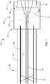
- FIG. 1illustrates a first fiber optic connector 20 connected to a fiber optic cable 46 to form a fiber optic connector and cable assembly 100 in accordance with the principles of the present disclosure.
- the fiber optic connector 20has a connector housing 32 that extends from a distal end 22 of the fiber optic connector 20 to a proximal end 24 of the fiber optic connector 20.
- the fiber optic connector 20includes a ferrule assembly 26 that mounts adjacent the distal end 22 of the connector housing 32.
- the ferrule assembly 26includes a ferrule 28, a hub and a spring 31.
- the ferrule assembly 26mounts at least partially within the fiber optic connector 20.
- the proximal end 24 of the fiber optic connector 20is configured to receive, anchor and provide strain relief/bend radius protection to a fiber optic cable 46.
- the fiber optic cable 46includes a cable jacket 48 surrounding at least one optical fiber 50 that is locked into place with an anchor mechanism 51.
- the fiber optic cable 46also includes at least one strength structure 52 formed by one or more strength members (e.g., reinforcing fibers such as aramid yarn/Kevlar).
- the anchor mechanism 51is any suitable device, system, or mechanism for anchoring the at least one optical fiber 50 either directly to the at least one strength structure 52 or indirectly to the at least one strength member 52 through an intermediate structure, such as the cable jacket 48. Accordingly, the anchor mechanism 51 anchors the at least one optical fiber 50 relative to the at least one strength structure 52.
- the anchor mechanism 51is any suitable device, system, or mechanism for anchoring the at least one optical fiber 50 to the cable jacket 48.
- the anchor mechanism 51prevents relative axial movement between the at least one strength member 52 and the at least one optical fiber 50.
- the anchor mechanism 51prevents relative axial movement at the anchor location between the at least one optical fiber 50, the at least one strength member 52, and the intermediate structure.
- the anchor mechanism 51provides for connection reliability and reliable optical performance.
- the anchor mechanism 51is positioned at a fiber anchoring location that is not at or coextensive with an optical fiber splice location.
- FIGS. 1-5illustrate example embodiments of a fiber optic cable 46.
- FIG. 1illustrates an embodiment of a fiber optic cable 46 with four optical fibers 50. It is appreciated that any number of optical fibers 50, such as 1, 4, 8, 12, or etc., may be utilized by the present disclosure.
- the fiber optic cable 46also includes at least one strength structure 52 formed by one or more strength members (e.g., reinforcing fibers such as aramid yarn/Kevlar).
- FIG. 1illustrates an example embodiment of two strength structures 52. It is appreciated that any number of strength structures 52, such as 1, 2, 3, 4, or etc., may be utilized by the present disclosure.
- the at least one strength structure 52is a strength layer formed around the at least one optical fiber 50.
- the at least one optical fiber 50is routed through an open space in the total length of the fiber optic cable 46 and through a fiber passage in the total length of the fiber optic connector 20.
- the at least one optical fiber 50further includes a distal portion secured within the ferrule 28. Further details regarding a fiber optic cable are found in U.S. Application Serial No. 12/607,748, filed on October 10, 2009 .
- the fiber optic connector 20is adapted to be mechanically coupled to a like fiber optic connector by an intermediate fiber optic adapter. Further details regarding the fiber optic adapter are found in U.S. Patent No. 5,214,730 .
- the ferrule 28 of the ferrule assembly 26includes a distal end face and a proximal end face.
- the distal end face of the ferrule 28is positioned distally outwardly beyond a distal end 22 of the connector housing 32 and the proximal end face of the ferrule 28 is positioned within the connector housing 32.
- the ferrule hub and the spring 31are captured between the distal end 22 and the proximal end 24 of the connector housing 32.
- the spring 31is configured to bias the ferrule 28 in a distal direction relative to the connector housing 32.
- the ferrule 28is movable in a proximal direction relative to the fiber optic connector 20 from a distal position to a proximal position.
- the distal position and the proximal positionare separated by an axial displacement distance AD.
- ADaxial displacement distance
- the proximal movement of the ferrule 28is against a bias of the spring 31.
- the at least one strength structure 52provides tensile reinforcement to the fiber optic cable 46.
- the at least one strength structure 52also functions as a separator for separating the at least one optical fiber 50 from the cable jacket 48.
- the at least one strength member 52is positioned between the at least one optical fiber 50 and the jacket 48.
- the at least one strength structure 52is attached to the cable jacket 48.
- the at least one strength structure 52is not attached to the jacket 48 and slides within the cable jacket 48. Further details regarding the strength structure are found in U.S. Patent Application Publication No. 2009/0297104, filed on May 28, 2009 .
- the anchor mechanism 51is any suitable device, system, or mechanism for anchoring the at least one optical fiber 50 relative to the at least one strength structure 52.
- the anchor mechanism 51either directly anchors the at least one optical fiber 50 to the at least one strength member 52 or indirectly anchors the at least one optical fiber 50 to the at least one strength member 52 through an intermediate structure.
- the anchor mechanism 51anchors the at least one optical fiber 50 to the cable jacket 48 and/or the strength structure 52.
- the anchor mechanism 51anchors the at least one optical fiber 50 to the at least one strength structure 52.
- the anchor mechanism 51is any suitable device, system, or mechanism for anchoring the at least one optical fiber 50 to the cable jacket 48.
- the at least one optical fiber 50extends through a fiber passage extending the total length of the fiber optic connector 20.
- the at least one optical fiber 50extends through the connector housing 32 and the ferrule 28.
- a portion of the at least one optical fiber 50 extending proximally from the ferrule 28 through the fiber optic connector 20 to the jacketed portion of the fiber optic cable 46includes a core, cladding layer and one or more coating layers.
- the portion of the at least one optical fiber 50 extending through the ferrule 28includes the core and the cladding layer.
- the fiber optic connector 20is a pull-proof connector in which the at least one strength structure 52 of the fiber optic cable 46 is anchored to the connector housing 32 thereby preventing tensile loads from being transferred to the ferrule assembly 26. Because of this configuration, movement of the ferrule 28 in a proximal direction relative to the connector housing 32 causes the at least one optical fiber 50 to be forced/displaced in a proximal direction relative to the connector housing 32 and the jacket 48 of the fiber optic cable 46. In the depicted embodiment, the ferrule 28 has a maximum axial displacement AD in the proximal direction during the connection process. The axial displacement AD creates an excess length of fiber having a length equal to the length of the axial displacement AD.
- the at least one optical fiber 50can also be affected and/or displaced by axial stretching, axial pulling, axial shrinking, axial shortening, and/or coiling of the jacket 48 of the fiber optic cable 46.
- axial elongation of the jacket 48can cause tension to be transferred to the one or more optical fibers 50 causing the one or more optical fibers 50 to pull back on the ferrule 28 against the bias of the spring 31. With the ferrule 28 pulled back, the ability to provide an effective optical connection with another optical connector can be compromised. In the case of multi-fiber ferrules, the pull back force transferred from the optical fibers 50 to the ferrule 28 can easily overcome the spring load of the spring 31 without exceeding the breaking points of the individual optical fibers 50. Absent the anchor mechanism 51, axial shrinking/shortening of the jacket 48 caused by temperature variations or coiling of the cable can cause excess optical fiber length to be forced inside the connector 20 thereby causing microbending of the optical fibers 50 and signal degradation.
- the anchor mechanism 51 of the present disclosurelessens and/or prevents this undesirable movement of the ferrule 28 and the at least one optical fiber 50. Accordingly, the anchor mechanism 51 described herein provides for a fiber optic connector and cable assembly 100 that has more reliable connections and more reliable optical performance than previously utilized fiber optic cable and connector assemblies that do not utilize an anchor mechanism 51.
- the anchor mechanism 51may be any suitable device, system, or mechanism for anchoring the at least one optical fiber 50 into place within the fiber optic cable 46.
- the anchor mechanism 51prevents an axial load on the at least one optical fiber 50 from transferring through the at least one optical fiber 50 in either direction across the anchor mechanism 51.
- the prevention of load transferprevents any optical fiber movement within the open space of the fiber optic cable 46 from being transferred to the distal end of the at least one optical fiber 50 that is secured to the ferrule 28.
- the prevention of load transferwill also prevent movement of the at least one optical fiber 50 cause by any axial displacement of the ferrule 28 from being transferred across the anchor mechanism 51.
- the location of the anchor mechanism 51 in the fiber optic cable 46is located at a predetermined distance D from the proximal end 24 of the connector housing 32.
- the predetermined distance Dis enough distance to accommodate acceptable macrobending of the at least one optical fiber 50 in response to the axial displacement AD of the ferrule 28.
- the fiber optic cable 46has a diameter that is large enough to take-up an excess length of the at least one optical fiber 50 that corresponds to the axial displacement distance of the ferrule 28 to accommodate for acceptable macrobending of the at least one optical fiber 50.
- the predetermined distance Dmay be adjacent to the fiber optic connector 20 if the fiber optic connector 20 itself includes an internal fiber take-up region_(e.g., see the fiber optic connector disclosed in U.S. Patent Application No. 13/420,286 , entitled Fiber Optic Connector that claims priority to U.S. Provisional Patent Application having Attorney Docket No. 02316.3202USP2 and Application Serial No. 61/510,711 , filed on the date concurrent herewith.
- the predetermined distance Dpreferably provides enough space within the fiber optic cable 46 to accommodate acceptable macrobending of the at least one optical fiber 50 in response to the axial displacement AD of the ferrule 28.
- the predetermined distanceis from about 12.7 cm (5 inches) to about 0.914 m (3 feet). In some embodiments, the predetermined distance is from about 15.24 cm (6 inches) to about 0.457 m (1.5 feet). In further embodiments, the predetermined distance is from about 0.305 m (1 foot) to about 0.61 (2 feet). In further embodiments, the predetermined distance is from about 1 foot. In other embodiments, the predetermined distance is from about 0.457 m (1.5 feet) to about 0.762 m (2.5 feet).
- the anchor mechanism 51is an adhesive, a curable substance, and/or a securing medium, such as epoxy.
- the adhesiveis injected with a needle through the cable jacket 48 into the open space of the fiber optic cable 46.
- a cable jacket 48is cut open to create an open window 60 through which the adhesive is applied to the at least one optical fiber 50.
- the open window 60may be sealed by utilizing a heat shrink wrap applied over the cable jacket 48.
- the anchor mechanism 51is a permanently deformed portion of the cable jacket 48 that has been deformed by a hot press of the cable jacket 48 to lock the at least one optical fiber 50 in place within the fiber optic cable 46.
- the anchor mechanism 51is a heat shrink wrap or crimp applied over the cable jacket 48 to compress the cable jacket 48 to lock the at least one optical fiber 50 in place within the fiber optic cable 46.
- the anchor mechanism 51includes a locking device such as a clip or retainer secured to the inside of the jacket 48.
- the locking devicecan be placed at least partially inside the fiber optic cable 46 through an open window 60 in the jacket 48.
- the locking deviceis a solid structure located at least partially within the jacket 48 and holds or locks the at least one fiber in place relative to the at least one strength structure 52, such as a clip.
- the locking devicemay include a biasing member and/or one or more catches 54 for locking the clip or crimp into place within the open space of the fiber optic cable 46.
- the catches 54inhibit axial movement of the locking devices relative to the at least one strength structure 52.
- the anchor mechanism 51utilizes an adhesive in addition to the locking device.
- the locking devicescan include receptacles (e.g., channels, openings, pockets, etc.) for receiving the optical fibers 50.
- Adhesivecan be used to anchor the optical fibers 50 within the receptacles.
- the open window 60is sealed by utilizing a heat shrink layer around the fiber optic cable 46 to seal off the open window 60.
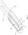
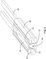
- FIGS. 2 , 4 , and 6illustrates a top view of an embodiment of a fiber optic cable 46 having an open window 60.
- FIGS. 3 , 5 , and 7illustrate a cross-sectional view of an embodiment of a fiber optic cable 46.
- FIGS. 2 , 4 , and 6illustrate an anchor mechanism 51 shown in the open window 60 of the fiber optic cable 46.
- the anchor mechanisms 51 in FIGS. 2 , 4 , and 6are each a view of a different locking device.
- FIGS. 3 , 4 , and 5each show an isometric, cross-section view of the different locking devices illustrated in FIGS. 2 , 4 , and 6 .
- 3 , 4 , and 5show different embodiments of a clip that has one or more catches 54.
- Catches 54embed into the intermediate structure, such as the cable jacket 48, and/or the at least one strength structure 52 to lock the clip into place in the open space within the fiber optic cable 46.
- the clipsfurther include a biasing member.
- the biasing memberbiases the one or more catches 54 into the intermediate structure and/or the at least one strength structure 52.
- the anchor mechanism 51further includes the use of adhesive to lock the at least one optical fiber 50 into place within the fiber optic cable 46.
- the clip illustrated in FIGS. 2 and 3has an open portion 56 that opens toward the open window 60. Further, the clip illustrated in FIGS. 2 and 3 has five catches 54 that embed into the cable jacket 48.
- the clip illustrated in FIGS. 4 and 5has an open portion 56 that opens away from the open window 60. Further, the clip illustrated in FIGS. 4 and 5 has four catches 54 that embed into the cable jacket 48.
- the clip illustrated in FIGS. 4 and 5also include a biasing member. The biasing member is inherent to the clip and biases or pushes curved ends 55 and the catches 54 of the clip into the cable jacket 48.
- the clip illustrated in FIGS. 6 and 7has an open portion 56 that opens toward the open window 60. Further, the clip illustrated in FIGS. 6 and 7 has two catches 54 that embed into the cable jacket 48. The clip illustrated in FIGS. 6 and 7 also include a biasing member for embedding the clip and the catches 54 into the cable jacket 48. Additionally, the clip illustrated in FIGS. 6 and 7 include two wings or clasps 58 for anchoring the clip into a position within the cable jacket 48.
Landscapes
- Physics & Mathematics (AREA)
- General Physics & Mathematics (AREA)
- Optics & Photonics (AREA)
- Mechanical Coupling Of Light Guides (AREA)
Description
- The present disclosure relates generally to a fiber optic connector and cable assembly.
- Fiber optic communication systems are becoming prevalent in part because service providers want to deliver high bandwidth communication capabilities (e.g., data and voice) to customers. Fiber optic communication systems employ a network of fiber optic cables to transmit large volumes of data and voice signals over relatively long distances. Optical fiber connectors are an important part of most fiber optic communication systems. Fiber optic connectors allow two optical fibers to be quickly optically connected without requiring a splice. Fiber optic connectors can be used to optically interconnect two lengths of optical fiber. Fiber optic connectors can also be used to interconnect lengths of optical fiber to passive and active equipment.
- A typical fiber optic connector includes a ferrule assembly supported at a distal end of a connector housing. A spring is used to bias the ferrule assembly in a distal direction relative to the connector housing. The ferrule functions to support an end portion of at least one optical fiber (in the case of a multi-fiber ferrule, the ends of multiple fibers are supported). The ferrule has a distal end face at which a polished end of the optical fiber is located. When two fiber optic connectors are interconnected, the distal end faces of the ferrules abut one another and the ferrules are forced proximally relative to their respective connector housings against the bias of their respective springs. With the fiber optic connectors connected, their respective optical fibers are coaxially aligned such that the end faces of the optical fibers directly oppose one another. In this way, an optical signal can be transmitted from optical fiber to optical fiber through the aligned end faces of the optical fibers. For many fiber optic connector styles, alignment between two fiber optic connectors is provided through the use of an intermediate fiber optic adapter.
- A fiber optic connector is often secured to the end of a corresponding fiber optic cable by anchoring strength structures of the cable to the connector housing of the connector. Anchoring is typically accomplished through the use of conventional techniques such as crimps or adhesive. Anchoring the strength structures of the cable to the connector housing is advantageous because it allows tensile load applied to the cable to be transferred from the strength structures of the cable directly to the connector housing. In this way, the tensile load is not transferred to the ferrule assembly of the fiber optic connector. If the tensile load were to be applied to the ferrule assembly, such tensile load could cause the ferrule assembly to be pulled in a proximal direction against the bias of the connector spring thereby possibly causing an optical disconnection between the connector and its corresponding mated connector. Fiber optic connectors of the type described above can be referred to as pull-proof connectors.
US 2009/0148101 A1 discloses a fiber optic connector and cable assembly, comprising a fiber optic connector including a connector housing having a distal end and a proximal end. The fiber optic connector including a ferrule assembly having a ferrule and a spring, the ferrule having a distal end face that is accessible at the distal end of the connector housing, the spring being between the distal end and the proximal end of the connector housing, the spring biasing the ferrule in a distal direction relative to the connector housing, the ferrule being movable in a proximal direction relative to the fiber optic connector from a distal position to a proximal position. The distal position and the proximal positon are separated by an axial displacement distance and a proximal movement of the ferrule is against a bias of the spring. The fiber optic connector and cable assembly comprises a cable having at least one fiber, a cable jacket that contacts the fiber and first and second strength members on opposite sides of the fiber. A pressure clamp can be used to secure the cable. Because the strength members are much larger in size than the fiber, the force of the clamp compresses down on the strength members but does not clamp down on the fibers.US 2008/0175541 A1 teaches a similar fiber optic connector and cable assembly. TheUS 2008/0175541 A1 further teaches a cable including a buffer tube with one fiber, strength members positioned on opposite sides of the buffer tube. The buffer tube and the strength members are positioned within an outer jacket of the cable.US 2009/0148101 A1 teaches a further similar fiber optic connector and cable assembly. TheUS 2009/0148101 A1 further teaches a cable including an outer jacket, a buffer tube positioned around an optical fiber and strength members positioned on opposite sides of the buffer tube. The buffer tube and strength are positioned within the outer jacket.- The technical problem is to provide an improved fiber optic connector and cable assembly.
- The technical problem is solved by a fiber optic connector and cable assembly with the features of claim 1. Further embodiments are mentioned in the dependent claims.
Fig. 1 is a schematic section view of an embodiment of a fiber optic cable and fiber optic connector in accordance with the principles of the present disclosure;Fig. 2 is a top view of an embodiment of a fiber optic cable having an open window in accordance with the principles of the present disclosure;Fig. 3 is an isometric, cross-sectional view of an embodiment of the fiber optic cable illustrated inFig. 2 in accordance with the principles of the present disclosure;Fig. 4 is a top view of an embodiment of a fiber optic cable having an open window in accordance with the principles of the present disclosure;Fig. 5 is an isometric, cross-sectional view of an embodiment of the fiber optic cable illustrated inFig. 4 in accordance with the principles of the present disclosure;Fig. 6 is a top view of an embodiment of a fiber optic cable having an open window in accordance with the principles of the present disclosure; andFig. 7 is an isometric, cross-sectional view of an embodiment of the fiber optic cable illustrated inFig. 6 in accordance with the principles of the present disclosure.Figure 1 illustrates a first fiberoptic connector 20 connected to a fiberoptic cable 46 to form a fiber optic connector andcable assembly 100 in accordance with the principles of the present disclosure. The fiberoptic connector 20 has aconnector housing 32 that extends from adistal end 22 of the fiberoptic connector 20 to aproximal end 24 of the fiberoptic connector 20. The fiberoptic connector 20 includes aferrule assembly 26 that mounts adjacent thedistal end 22 of theconnector housing 32. Theferrule assembly 26 includes aferrule 28, a hub and aspring 31. Theferrule assembly 26 mounts at least partially within the fiberoptic connector 20. Theproximal end 24 of the fiberoptic connector 20 is configured to receive, anchor and provide strain relief/bend radius protection to a fiberoptic cable 46.- The fiber
optic cable 46 includes acable jacket 48 surrounding at least oneoptical fiber 50 that is locked into place with ananchor mechanism 51. The fiberoptic cable 46 also includes at least onestrength structure 52 formed by one or more strength members (e.g., reinforcing fibers such as aramid yarn/Kevlar). In some embodiments, theanchor mechanism 51, is any suitable device, system, or mechanism for anchoring the at least oneoptical fiber 50 either directly to the at least onestrength structure 52 or indirectly to the at least onestrength member 52 through an intermediate structure, such as thecable jacket 48. Accordingly, theanchor mechanism 51 anchors the at least oneoptical fiber 50 relative to the at least onestrength structure 52. In an alternative embodiment, theanchor mechanism 51 is any suitable device, system, or mechanism for anchoring the at least oneoptical fiber 50 to thecable jacket 48. - At the anchor location, the
anchor mechanism 51 prevents relative axial movement between the at least onestrength member 52 and the at least oneoptical fiber 50. In some embodiments, when the at least oneoptical fiber 50 is indirectly anchored to the at least onestrength member 52 by theanchor mechanism 51, theanchor mechanism 51 prevents relative axial movement at the anchor location between the at least oneoptical fiber 50, the at least onestrength member 52, and the intermediate structure. Accordingly, theanchor mechanism 51 provides for connection reliability and reliable optical performance. Preferably, theanchor mechanism 51 is positioned at a fiber anchoring location that is not at or coextensive with an optical fiber splice location. FIGS. 1-5 illustrate example embodiments of a fiberoptic cable 46.FIG. 1 illustrates an embodiment of a fiberoptic cable 46 with fouroptical fibers 50. It is appreciated that any number ofoptical fibers 50, such as 1, 4, 8, 12, or etc., may be utilized by the present disclosure. Thefiber optic cable 46 also includes at least onestrength structure 52 formed by one or more strength members (e.g., reinforcing fibers such as aramid yarn/Kevlar).FIG. 1 illustrates an example embodiment of twostrength structures 52. It is appreciated that any number ofstrength structures 52, such as 1, 2, 3, 4, or etc., may be utilized by the present disclosure. In some embodiments, not illustrated, the at least onestrength structure 52 is a strength layer formed around the at least oneoptical fiber 50. The at least oneoptical fiber 50 is routed through an open space in the total length of thefiber optic cable 46 and through a fiber passage in the total length of thefiber optic connector 20. The at least oneoptical fiber 50 further includes a distal portion secured within theferrule 28. Further details regarding a fiber optic cable are found inU.S. Application Serial No. 12/607,748, filed on October 10, 2009 - It will be appreciated that the
fiber optic connector 20 is adapted to be mechanically coupled to a like fiber optic connector by an intermediate fiber optic adapter. Further details regarding the fiber optic adapter are found inU.S. Patent No. 5,214,730 . - Referring to
Fig. 1 , theferrule 28 of theferrule assembly 26 includes a distal end face and a proximal end face. The distal end face of theferrule 28 is positioned distally outwardly beyond adistal end 22 of theconnector housing 32 and the proximal end face of theferrule 28 is positioned within theconnector housing 32. When theconnector housing 32 is assembled as shown atFig. 1 , the ferrule hub and thespring 31 are captured between thedistal end 22 and theproximal end 24 of theconnector housing 32. As so configured, thespring 31 is configured to bias theferrule 28 in a distal direction relative to theconnector housing 32. Accordingly theferrule 28 is movable in a proximal direction relative to thefiber optic connector 20 from a distal position to a proximal position. The distal position and the proximal position are separated by an axial displacement distance AD. Thus, the proximal movement of theferrule 28 is against a bias of thespring 31. When two of thefiber optic connectors 20 are interconnected, theirferrules 28 are forced to move in proximal directions relative to theirrespective connector housings 32 against the bias of theirrespective springs 31. The movement is along the central axes of the matedfiber optic connectors 20. - The at least one
strength structure 52 provides tensile reinforcement to thefiber optic cable 46. In addition to providing tensile strength to thefiber optic cable 46, in some embodiments, the at least onestrength structure 52 also functions as a separator for separating the at least oneoptical fiber 50 from thecable jacket 48. For example, in some embodiments, the at least onestrength member 52 is positioned between the at least oneoptical fiber 50 and thejacket 48. In some embodiments, the at least onestrength structure 52 is attached to thecable jacket 48. In other embodiments, the at least onestrength structure 52 is not attached to thejacket 48 and slides within thecable jacket 48. Further details regarding the strength structure are found inU.S. Patent Application Publication No. 2009/0297104, filed on May 28, 2009 . - As discussed above, in some embodiments, the
anchor mechanism 51, is any suitable device, system, or mechanism for anchoring the at least oneoptical fiber 50 relative to the at least onestrength structure 52. For example, theanchor mechanism 51 either directly anchors the at least oneoptical fiber 50 to the at least onestrength member 52 or indirectly anchors the at least oneoptical fiber 50 to the at least onestrength member 52 through an intermediate structure. In one embodiment, when the at least onestrength structure 52 is attached to thecable jacket 48, theanchor mechanism 51 anchors the at least oneoptical fiber 50 to thecable jacket 48 and/or thestrength structure 52. In another embodiment, when the at least onestrength structure 52 is not attached to thecable jacket 48, theanchor mechanism 51 anchors the at least oneoptical fiber 50 to the at least onestrength structure 52. As discussed above, in alternative embodiments, theanchor mechanism 51, is any suitable device, system, or mechanism for anchoring the at least oneoptical fiber 50 to thecable jacket 48. - As shown in
Fig. 1 , the at least oneoptical fiber 50 extends through a fiber passage extending the total length of thefiber optic connector 20. For example, the at least oneoptical fiber 50 extends through theconnector housing 32 and theferrule 28. In certain embodiments, a portion of the at least oneoptical fiber 50 extending proximally from theferrule 28 through thefiber optic connector 20 to the jacketed portion of thefiber optic cable 46 includes a core, cladding layer and one or more coating layers. In some embodiments, the portion of the at least oneoptical fiber 50 extending through theferrule 28 includes the core and the cladding layer. - The
fiber optic connector 20 is a pull-proof connector in which the at least onestrength structure 52 of thefiber optic cable 46 is anchored to theconnector housing 32 thereby preventing tensile loads from being transferred to theferrule assembly 26. Because of this configuration, movement of theferrule 28 in a proximal direction relative to theconnector housing 32 causes the at least oneoptical fiber 50 to be forced/displaced in a proximal direction relative to theconnector housing 32 and thejacket 48 of thefiber optic cable 46. In the depicted embodiment, theferrule 28 has a maximum axial displacement AD in the proximal direction during the connection process. The axial displacement AD creates an excess length of fiber having a length equal to the length of the axial displacement AD. - The at least one
optical fiber 50 can also be affected and/or displaced by axial stretching, axial pulling, axial shrinking, axial shortening, and/or coiling of thejacket 48 of thefiber optic cable 46. - Absent the
anchor mechanism 51, axial elongation of thejacket 48 can cause tension to be transferred to the one or moreoptical fibers 50 causing the one or moreoptical fibers 50 to pull back on theferrule 28 against the bias of thespring 31. With theferrule 28 pulled back, the ability to provide an effective optical connection with another optical connector can be compromised. In the case of multi-fiber ferrules, the pull back force transferred from theoptical fibers 50 to theferrule 28 can easily overcome the spring load of thespring 31 without exceeding the breaking points of the individualoptical fibers 50. Absent theanchor mechanism 51, axial shrinking/shortening of thejacket 48 caused by temperature variations or coiling of the cable can cause excess optical fiber length to be forced inside theconnector 20 thereby causing microbending of theoptical fibers 50 and signal degradation. - With regard to the undesirable movement of the
ferrule 28 and the at least one fiber as described above, theanchor mechanism 51 of the present disclosure lessens and/or prevents this undesirable movement of theferrule 28 and the at least oneoptical fiber 50. Accordingly, theanchor mechanism 51 described herein provides for a fiber optic connector andcable assembly 100 that has more reliable connections and more reliable optical performance than previously utilized fiber optic cable and connector assemblies that do not utilize ananchor mechanism 51. - As discussed above, the
anchor mechanism 51 may be any suitable device, system, or mechanism for anchoring the at least oneoptical fiber 50 into place within thefiber optic cable 46. Theanchor mechanism 51 prevents an axial load on the at least oneoptical fiber 50 from transferring through the at least oneoptical fiber 50 in either direction across theanchor mechanism 51. The prevention of load transfer, prevents any optical fiber movement within the open space of thefiber optic cable 46 from being transferred to the distal end of the at least oneoptical fiber 50 that is secured to theferrule 28. However, the prevention of load transfer will also prevent movement of the at least oneoptical fiber 50 cause by any axial displacement of theferrule 28 from being transferred across theanchor mechanism 51.
Accordingly, the location of theanchor mechanism 51 in thefiber optic cable 46 is located at a predetermined distance D from theproximal end 24 of theconnector housing 32. The predetermined distance D is enough distance to accommodate acceptable macrobending of the at least oneoptical fiber 50 in response to the axial displacement AD of theferrule 28. Further, thefiber optic cable 46 has a diameter that is large enough to take-up an excess length of the at least oneoptical fiber 50 that corresponds to the axial displacement distance of theferrule 28 to accommodate for acceptable macrobending of the at least oneoptical fiber 50. - For example, the predetermined distance D may be adjacent to the
fiber optic connector 20 if thefiber optic connector 20 itself includes an internal fiber take-up region_(e.g., see the fiber optic connector disclosed inU.S. Patent Application No. 13/420,286 , entitled Fiber Optic Connector that claims priority to U.S. Provisional Patent Application having Attorney Docket No. 02316.3202USP2 and Application Serial No.61/510,711 fiber optic connector 20 does not include a fiber take-up region, the predetermined distance D preferably provides enough space within thefiber optic cable 46 to accommodate acceptable macrobending of the at least oneoptical fiber 50 in response to the axial displacement AD of theferrule 28. In some embodiments, the predetermined distance is from about 12.7 cm (5 inches) to about 0.914 m (3 feet). In some embodiments, the predetermined distance is from about 15.24 cm (6 inches) to about 0.457 m (1.5 feet). In further embodiments, the predetermined distance is from about 0.305 m (1 foot) to about 0.61 (2 feet). In further embodiments, the predetermined distance is from about 1 foot. In other embodiments, the predetermined distance is from about 0.457 m (1.5 feet) to about 0.762 m (2.5 feet). - In some embodiments, the
anchor mechanism 51 is an adhesive, a curable substance, and/or a securing medium, such as epoxy. In some embodiments, the adhesive is injected with a needle through thecable jacket 48 into the open space of thefiber optic cable 46. In other embodiments, acable jacket 48 is cut open to create anopen window 60 through which the adhesive is applied to the at least oneoptical fiber 50. In these embodiments, theopen window 60 may be sealed by utilizing a heat shrink wrap applied over thecable jacket 48. - In other embodiments, the
anchor mechanism 51 is a permanently deformed portion of thecable jacket 48 that has been deformed by a hot press of thecable jacket 48 to lock the at least oneoptical fiber 50 in place within thefiber optic cable 46. In other embodiments, theanchor mechanism 51 is a heat shrink wrap or crimp applied over thecable jacket 48 to compress thecable jacket 48 to lock the at least oneoptical fiber 50 in place within thefiber optic cable 46. - In some embodiments, the
anchor mechanism 51 includes a locking device such as a clip or retainer secured to the inside of thejacket 48. The locking device can be placed at least partially inside thefiber optic cable 46 through anopen window 60 in thejacket 48. The locking device is a solid structure located at least partially within thejacket 48 and holds or locks the at least one fiber in place relative to the at least onestrength structure 52, such as a clip. The locking device may include a biasing member and/or one ormore catches 54 for locking the clip or crimp into place within the open space of thefiber optic cable 46. Thecatches 54 inhibit axial movement of the locking devices relative to the at least onestrength structure 52. In some embodiments, theanchor mechanism 51 utilizes an adhesive in addition to the locking device. The locking devices can include receptacles (e.g., channels, openings, pockets, etc.) for receiving theoptical fibers 50. Adhesive can be used to anchor theoptical fibers 50 within the receptacles. As discussed above, in some embodiments, theopen window 60 is sealed by utilizing a heat shrink layer around thefiber optic cable 46 to seal off theopen window 60. FIGS. 2 ,4 , and6 illustrates a top view of an embodiment of afiber optic cable 46 having anopen window 60.FIGS. 3 ,5 , and7 illustrate a cross-sectional view of an embodiment of afiber optic cable 46.FIGS. 2 ,4 , and6 illustrate ananchor mechanism 51 shown in theopen window 60 of thefiber optic cable 46. Theanchor mechanisms 51 inFIGS. 2 ,4 , and6 are each a view of a different locking device.FIGS. 3 ,4 , and5 each show an isometric, cross-section view of the different locking devices illustrated inFIGS. 2 ,4 , and6 . For example, the locking devices illustrated inFIGS. 3 ,4 , and5 show different embodiments of a clip that has one or more catches 54.Catches 54 embed into the intermediate structure, such as thecable jacket 48, and/or the at least onestrength structure 52 to lock the clip into place in the open space within thefiber optic cable 46. In some embodiments, the clips further include a biasing member. In some embodiments the biasing member biases the one ormore catches 54 into the intermediate structure and/or the at least onestrength structure 52. In other embodiments, theanchor mechanism 51 further includes the use of adhesive to lock the at least oneoptical fiber 50 into place within thefiber optic cable 46.- For example, the clip illustrated in
FIGS. 2 and3 has anopen portion 56 that opens toward theopen window 60. Further, the clip illustrated inFIGS. 2 and3 has fivecatches 54 that embed into thecable jacket 48. - The clip illustrated in
FIGS. 4 and5 has anopen portion 56 that opens away from theopen window 60. Further, the clip illustrated inFIGS. 4 and5 has fourcatches 54 that embed into thecable jacket 48. The clip illustrated inFIGS. 4 and5 also include a biasing member. The biasing member is inherent to the clip and biases or pushes curved ends 55 and thecatches 54 of the clip into thecable jacket 48. - The clip illustrated in
FIGS. 6 and7 has anopen portion 56 that opens toward theopen window 60. Further, the clip illustrated inFIGS. 6 and7 has twocatches 54 that embed into thecable jacket 48. The clip illustrated inFIGS. 6 and7 also include a biasing member for embedding the clip and thecatches 54 into thecable jacket 48. Additionally, the clip illustrated inFIGS. 6 and7 include two wings or clasps 58 for anchoring the clip into a position within thecable jacket 48. - Numerous other changes may be made which will readily suggest themselves to those skilled in the art and which are encompassed as defined in the claims. While various embodiments have been described for purposes of this disclosure, various changes and modifications may be made which are well within the scope of the present claims.
Claims (16)
- A fiber optic connector and cable assembly (100) comprising:a fiber optic connector (20) including a connector housing (32) having a distal end (22) and a proximal end (24);the fiber optic connector (20) including a ferrule assembly (26) having a ferrule (28) and a spring (31), the ferrule (28) having a distal end face that is accessible at the distal end (22) of the connector housing (32), the spring (31) being between the distal end (22) and the proximal end (24) of the connector housing (32), the spring (31) biasing the ferrule (28) in a distal direction relative to the connector housing (32), the ferrule (28) being movable in a proximal direction relative to the fiber optic connector (20) from a distal position to a proximal position, the distal position and the proximal position being separated by an axial displacement distance (AD), a proximal movement of the ferrule (28) being against a bias of the spring (31);a fiber optic cable (46) including at least one optical fiber (50) contained within a cable jacket (48), the fiber optic cable (46) also including at least one strength structure (52) for providing tensile reinforcement to the fiber optic cable (46), the at least one strength structure (52) being anchored to the connector housing (32) adjacent the proximal end (24) of the connector housing (32), the at least one optical fiber (50) extending through a fiber passage of the fiber optic connector (20) from the proximal end (24) of the connector housing (32) to the ferrule (28), the at least one optical fiber (50) having a distal portion potted within the ferrule (28); andthe at least one optical fiber being anchored at an anchoring location positioned within the fiber optic cable, the anchoring location being spaced from the proximal end (24) of the connector housing, the part of the at least one optical fiber (50) extending through a fiber passage of the fiber optic connector from the proximal end (24) of the connector housing (32) to the ferrule (28) being anchored to at least one of the cable jacket (48) and the at least one strength structure (52) to prevent axial movement of the at least one optical fiber relative to at least one of the cable jacket and the at least one strength structure at the anchoring location.
- The fiber optic connector and cable assembly of claim 1, wherein the anchoring location prevents an axial load on the at least one optical fiber (50) from transferring across the anchoring location.
- The fiber optic connector and cable assembly of claim 1, wherein the anchoring location is about 12,7 cm to about 0,914 m away from a proximal end (24) of the connector housing (32).
- The fiber optic connector and cable assembly of claim 3, wherein the fiber optic cable (46) has diameter that is large enough to take-up an excess length of the at least one optical fiber (50) that corresponds to the axial displacement distance (AD) of the ferrule (28) to accommodate for acceptable macrobending of the at least one optical fiber (50).
- The fiber optic connector and cable assembly of claim 1, wherein the at least one optical fiber is anchored by an adhesive.
- The fiber optic connector and cable assembly of claim 1, wherein the anchoring location is a permanently deformed portion of the cable j acket (48) by a hot press of the cable jacket (48) to lock the at least one optical fiber (50) in place within the fiber optic cable (46).
- The fiber optic connector and cable assembly of claim 1, wherein the at least one optical fiber is anchored by a heat shrink that is applied over the cable jacket (48).
- The fiber optic connector and cable assembly of claim 1, wherein the at least one optical fiber is anchored by a locking device.
- The fiber optic connector and cable assembly of claim 8, wherein the locking device is a clip.
- The fiber optic connector and cable assembly of claim 9, wherein the clip has at least one catch (54) that embeds into at least one of the at least one strength structure (52) and the cable jacket (48) to lock the clip into place in an open space within the fiber optic cable (46); wherein the clip further includes a biasing member to lock the clip into place in the open space within the fiber optic cable (46).
- The fiber optic connector and cable assembly of claim 8, wherein the locking device has a biasing member to hold the locking device into place in an open space within the fiber optic cable (46).
- The fiber optic connector and cable assembly of claim 8, wherein the locking device is inserted into the fiber optic cable (46) through an open window (60) on the cable jacket (48).
- The fiber optic connector and cable assembly of claim 8, wherein the at least one optical fiber is further anchored by an adhesive.
- The fiber optic connector and cable assembly of claim 1, wherein the at least one strength structure (52) is attached to the cable jacket (48), and wherein the at least one optical fiber (50) is anchored directly to the at least one strength structure (52) at the anchoring location.
- The fiber optic connector and cable assembly of claim 1, wherein the at least one strength structure (52) is attached to the cable jacket (48); and the at least one optical fiber (50) being anchored indirectly to the at least one strength structure (52) by anchoring the at least one optical fiber (50) to the cable jacket (48) at the anchoring location.
- The fiber optic connector and cable assembly of claim 1, wherein the at least one strength structure (52) is not attached to the cable jacket (48); and wherein the at least one optical fiber (50) is anchored directly to the at least one strength structure (52) at the anchoring location.
Applications Claiming Priority (3)
| Application Number | Priority Date | Filing Date | Title |
|---|---|---|---|
| US201161510888P | 2011-07-22 | 2011-07-22 | |
| US201161526996P | 2011-08-24 | 2011-08-24 | |
| PCT/US2012/047402WO2013016135A2 (en) | 2011-07-22 | 2012-07-19 | Fiber optic connector and cable assembly having a fiber locking mechanism |
Publications (3)
| Publication Number | Publication Date |
|---|---|
| EP2734881A2 EP2734881A2 (en) | 2014-05-28 |
| EP2734881A4 EP2734881A4 (en) | 2015-03-25 |
| EP2734881B1true EP2734881B1 (en) | 2019-05-08 |
Family
ID=47601720
Family Applications (1)
| Application Number | Title | Priority Date | Filing Date |
|---|---|---|---|
| EP12817330.9AActiveEP2734881B1 (en) | 2011-07-22 | 2012-07-19 | Fiber optic connector and cable assembly having a fiber locking mechanism |
Country Status (5)
| Country | Link |
|---|---|
| US (3) | US8864391B2 (en) |
| EP (1) | EP2734881B1 (en) |
| ES (1) | ES2734981T3 (en) |
| RU (1) | RU2603237C2 (en) |
| WO (1) | WO2013016135A2 (en) |
Families Citing this family (13)
| Publication number | Priority date | Publication date | Assignee | Title |
|---|---|---|---|---|
| RU2603237C2 (en) | 2011-07-22 | 2016-11-27 | Адс Телекоммьюникейшнз, Инк. | Unit of connection of fibre-optic cable with connector having fibre locking means |
| EP2737350A1 (en)* | 2011-07-29 | 2014-06-04 | Corning Cable Systems LLC | Fiber optic cable assemblies having a connector with a stable fiber length therein |
| US9829646B2 (en)* | 2013-11-04 | 2017-11-28 | CommScope Connectivity Belgium BVBA | Fiber optic connector having an optical fiber that is axially moveable within a ferrule |
| USD760167S1 (en) | 2014-05-01 | 2016-06-28 | Sonos, Inc. | Electrical plug-in connector |
| WO2016004347A1 (en)* | 2014-07-03 | 2016-01-07 | Adc Telecommunications, Inc. | Optical fiber connector for multi-fiber cable |
| EP3822676A1 (en) | 2015-04-02 | 2021-05-19 | CommScope Technologies LLC | Fiber optic network architecture using high fiber-count fiber optic connectors |
| USD796447S1 (en) | 2015-04-08 | 2017-09-05 | Sonos, Inc. | Power plug |
| EP3593187A4 (en) | 2017-03-07 | 2021-01-13 | CommScope Technologies LLC | System for locking optical fibers within a fiber optic cable |
| GB201707946D0 (en) | 2017-05-17 | 2017-06-28 | Optasense Holdings Ltd | Distributed fibre optic sensing |
| USD854016S1 (en) | 2017-09-28 | 2019-07-16 | Sonos, Inc. | Media plug adapter |
| TWM577968U (en)* | 2019-01-19 | 2019-05-11 | 擎宏電子企業有限公司 | Adapter board structure for power module of DC power supply |
| JP2021117439A (en)* | 2020-01-29 | 2021-08-10 | 株式会社フジクラ | Optical fiber cable and manufacturing method of optical fiber cable |
| RU201818U1 (en)* | 2020-06-23 | 2021-01-14 | Общество с ограниченной ответственностью "Медицинские технологии и инновации" | Connector for connecting the catheter light guide to a laser source |
Family Cites Families (26)
| Publication number | Priority date | Publication date | Assignee | Title |
|---|---|---|---|---|
| ATE93068T1 (en)* | 1988-12-05 | 1993-08-15 | Kupferdraht Isolierwerk Ag | SELF-SUPPORTING OPTICAL CABLE. |
| AU635172B2 (en) | 1991-05-13 | 1993-03-11 | Nippon Telegraph & Telephone Corporation | Multifiber optical connector plug with low reflection and low insertion loss |
| US5673352A (en) | 1996-01-12 | 1997-09-30 | Alcatel Submarine Networks, Inc. | Fiber optic micro cable |
| JPH10311934A (en)* | 1997-05-12 | 1998-11-24 | Kiyousera Elco Kk | Plastic optical fiber connectors |
| US6493491B1 (en) | 1999-09-28 | 2002-12-10 | Alcatel | Optical drop cable for aerial installation |
| US7113679B2 (en) | 2000-05-26 | 2006-09-26 | Corning Cable Systems, Llc | Fiber optic drop cables and preconnectorized assemblies having toning portions |
| US6542674B1 (en) | 2000-08-25 | 2003-04-01 | Corning Cable Systems Llc | Fiber optic cables with strength members |
| US6546175B1 (en) | 2000-05-26 | 2003-04-08 | Corning Cable Systems Llc | Self-supporting fiber optic cable |
| US7090407B2 (en) | 2000-05-26 | 2006-08-15 | Corning Cable Systems Llc | Preconnectorized fiber optic drop cables and assemblies for efficient deployment |
| US6953287B2 (en)* | 2003-11-06 | 2005-10-11 | 3M Innovative Properties Company | Anchor for fiber optic cable |
| US7221831B2 (en)* | 2005-03-03 | 2007-05-22 | Nexans | Multi-tube fiber optic cable and system and method for making the same |
| US7264402B2 (en) | 2005-03-10 | 2007-09-04 | Corning Cable Systems Llc | Multi-fiber optic receptacle and plug assembly |
| US20060291787A1 (en) | 2005-06-27 | 2006-12-28 | Seddon David A | Fiber optic cable having strength component |
| US7463803B2 (en) | 2005-11-14 | 2008-12-09 | Corning Cable Systems Llc | Drop cable with fiber optic connector and methods for fabricating same |
| WO2008021253A2 (en) | 2006-08-14 | 2008-02-21 | Adc Telecommunications, Inc. | Factory spliced cable assembly |
| US7840109B2 (en) | 2006-08-14 | 2010-11-23 | Adc Telecommunications, Inc. | Factory spliced cable assembly |
| US7400814B1 (en) | 2007-01-13 | 2008-07-15 | Furukawa Electric North America, Inc. | Wall-mountable optical fiber and cable management apparatus |
| US7572065B2 (en) | 2007-01-24 | 2009-08-11 | Adc Telecommunications, Inc. | Hardened fiber optic connector |
| US7567741B2 (en)* | 2007-11-26 | 2009-07-28 | Corning Cable Systems Llc | Fiber optic cables and assemblies for fiber toward the subscriber applications |
| US7762726B2 (en) | 2007-12-11 | 2010-07-27 | Adc Telecommunications, Inc. | Hardened fiber optic connection system |
| CN102016669A (en)* | 2008-04-25 | 2011-04-13 | 3M创新有限公司 | Field terminable LC format optical connector with splice element |
| WO2009155037A2 (en) | 2008-05-28 | 2009-12-23 | Adc Telecommunications, Inc. | Fiber optic cable |
| WO2010062646A1 (en) | 2008-10-28 | 2010-06-03 | Adc Telecommunications, Inc. | Flat drop cable |
| US7621675B1 (en) | 2009-02-13 | 2009-11-24 | Ofs Fitel, Llc | Single-piece cable retention housing for hardened outside plant connector |
| US8636425B2 (en) | 2011-03-15 | 2014-01-28 | Adc Telecommunications, Inc. | Fiber optic connector |
| RU2603237C2 (en) | 2011-07-22 | 2016-11-27 | Адс Телекоммьюникейшнз, Инк. | Unit of connection of fibre-optic cable with connector having fibre locking means |
- 2012
- 2012-07-19RURU2014106491/28Apatent/RU2603237C2/ennot_activeIP Right Cessation
- 2012-07-19ESES12817330Tpatent/ES2734981T3/enactiveActive
- 2012-07-19WOPCT/US2012/047402patent/WO2013016135A2/enactiveApplication Filing
- 2012-07-19EPEP12817330.9Apatent/EP2734881B1/enactiveActive
- 2012-07-19USUS13/552,856patent/US8864391B2/ennot_activeExpired - Fee Related
- 2014
- 2014-09-18USUS14/490,219patent/US9500816B2/enactiveActive
- 2016
- 2016-11-16USUS15/353,206patent/US10254495B2/enactiveActive
Non-Patent Citations (1)
| Title |
|---|
| None* |
Also Published As
| Publication number | Publication date |
|---|---|
| US8864391B2 (en) | 2014-10-21 |
| WO2013016135A2 (en) | 2013-01-31 |
| US10254495B2 (en) | 2019-04-09 |
| US20150104134A1 (en) | 2015-04-16 |
| US9500816B2 (en) | 2016-11-22 |
| WO2013016135A3 (en) | 2013-05-02 |
| ES2734981T3 (en) | 2019-12-13 |
| US20170192190A1 (en) | 2017-07-06 |
| EP2734881A4 (en) | 2015-03-25 |
| US20130183005A1 (en) | 2013-07-18 |
| EP2734881A2 (en) | 2014-05-28 |
| RU2603237C2 (en) | 2016-11-27 |
| RU2014106491A (en) | 2015-08-27 |
Similar Documents
| Publication | Publication Date | Title |
|---|---|---|
| EP2734881B1 (en) | Fiber optic connector and cable assembly having a fiber locking mechanism | |
| US9989711B2 (en) | Fiber optic connector and fiber optic cable assembly with fiber optic cable anchored to boot of fiber optic connector | |
| US20240142723A1 (en) | Fiber optic connector | |
| US20170212313A1 (en) | Fiber optic connector and fiber optic cable assembly with fiber optic cable anchored to boot of fiber optic connector | |
| US10302878B2 (en) | Methods for forming connectorized fiber optic cabling | |
| ES2710111T3 (en) | Improved traction coating for pulling a fiber optic cable along a conduit | |
| US7758257B2 (en) | Methods for forming connectorized fiber optic cabling | |
| US8702323B2 (en) | Strain relief boot for a fiber optic connector | |
| US11474309B2 (en) | Connectorized fiber optic cabling assembly | |
| US9664864B2 (en) | Method for terminating high fiber count cables | |
| US20240411100A1 (en) | Cable entry transition to a cassette for a fiber optic cable configured to reduce stress on an optical fiber and reduce signal loss |
Legal Events
| Date | Code | Title | Description |
|---|---|---|---|
| PUAI | Public reference made under article 153(3) epc to a published international application that has entered the european phase | Free format text:ORIGINAL CODE: 0009012 | |
| 17P | Request for examination filed | Effective date:20140109 | |
| AK | Designated contracting states | Kind code of ref document:A2 Designated state(s):AL AT BE BG CH CY CZ DE DK EE ES FI FR GB GR HR HU IE IS IT LI LT LU LV MC MK MT NL NO PL PT RO RS SE SI SK SM TR | |
| DAX | Request for extension of the european patent (deleted) | ||
| A4 | Supplementary search report drawn up and despatched | Effective date:20150220 | |
| RIC1 | Information provided on ipc code assigned before grant | Ipc:G02B 6/38 20060101AFI20150216BHEP | |
| STAA | Information on the status of an ep patent application or granted ep patent | Free format text:STATUS: EXAMINATION IS IN PROGRESS | |
| 17Q | First examination report despatched | Effective date:20180522 | |
| GRAP | Despatch of communication of intention to grant a patent | Free format text:ORIGINAL CODE: EPIDOSNIGR1 | |
| STAA | Information on the status of an ep patent application or granted ep patent | Free format text:STATUS: GRANT OF PATENT IS INTENDED | |
| INTG | Intention to grant announced | Effective date:20181219 | |
| GRAS | Grant fee paid | Free format text:ORIGINAL CODE: EPIDOSNIGR3 | |
| GRAA | (expected) grant | Free format text:ORIGINAL CODE: 0009210 | |
| STAA | Information on the status of an ep patent application or granted ep patent | Free format text:STATUS: THE PATENT HAS BEEN GRANTED | |
| AK | Designated contracting states | Kind code of ref document:B1 Designated state(s):AL AT BE BG CH CY CZ DE DK EE ES FI FR GB GR HR HU IE IS IT LI LT LU LV MC MK MT NL NO PL PT RO RS SE SI SK SM TR | |
| REG | Reference to a national code | Ref country code:GB Ref legal event code:FG4D | |
| REG | Reference to a national code | Ref country code:CH Ref legal event code:EP Ref country code:AT Ref legal event code:REF Ref document number:1131083 Country of ref document:AT Kind code of ref document:T Effective date:20190515 | |
| REG | Reference to a national code | Ref country code:IE Ref legal event code:FG4D | |
| REG | Reference to a national code | Ref country code:DE Ref legal event code:R096 Ref document number:602012059969 Country of ref document:DE | |
| REG | Reference to a national code | Ref country code:NL Ref legal event code:MP Effective date:20190508 | |
| REG | Reference to a national code | Ref country code:LT Ref legal event code:MG4D | |
| PG25 | Lapsed in a contracting state [announced via postgrant information from national office to epo] | Ref country code:SE Free format text:LAPSE BECAUSE OF FAILURE TO SUBMIT A TRANSLATION OF THE DESCRIPTION OR TO PAY THE FEE WITHIN THE PRESCRIBED TIME-LIMIT Effective date:20190508 Ref country code:PT Free format text:LAPSE BECAUSE OF FAILURE TO SUBMIT A TRANSLATION OF THE DESCRIPTION OR TO PAY THE FEE WITHIN THE PRESCRIBED TIME-LIMIT Effective date:20190908 Ref country code:AL Free format text:LAPSE BECAUSE OF FAILURE TO SUBMIT A TRANSLATION OF THE DESCRIPTION OR TO PAY THE FEE WITHIN THE PRESCRIBED TIME-LIMIT Effective date:20190508 Ref country code:NL Free format text:LAPSE BECAUSE OF FAILURE TO SUBMIT A TRANSLATION OF THE DESCRIPTION OR TO PAY THE FEE WITHIN THE PRESCRIBED TIME-LIMIT Effective date:20190508 Ref country code:LT Free format text:LAPSE BECAUSE OF FAILURE TO SUBMIT A TRANSLATION OF THE DESCRIPTION OR TO PAY THE FEE WITHIN THE PRESCRIBED TIME-LIMIT Effective date:20190508 Ref country code:HR Free format text:LAPSE BECAUSE OF FAILURE TO SUBMIT A TRANSLATION OF THE DESCRIPTION OR TO PAY THE FEE WITHIN THE PRESCRIBED TIME-LIMIT Effective date:20190508 Ref country code:NO Free format text:LAPSE BECAUSE OF FAILURE TO SUBMIT A TRANSLATION OF THE DESCRIPTION OR TO PAY THE FEE WITHIN THE PRESCRIBED TIME-LIMIT Effective date:20190808 Ref country code:FI Free format text:LAPSE BECAUSE OF FAILURE TO SUBMIT A TRANSLATION OF THE DESCRIPTION OR TO PAY THE FEE WITHIN THE PRESCRIBED TIME-LIMIT Effective date:20190508 | |
| PG25 | Lapsed in a contracting state [announced via postgrant information from national office to epo] | Ref country code:GR Free format text:LAPSE BECAUSE OF FAILURE TO SUBMIT A TRANSLATION OF THE DESCRIPTION OR TO PAY THE FEE WITHIN THE PRESCRIBED TIME-LIMIT Effective date:20190809 Ref country code:BG Free format text:LAPSE BECAUSE OF FAILURE TO SUBMIT A TRANSLATION OF THE DESCRIPTION OR TO PAY THE FEE WITHIN THE PRESCRIBED TIME-LIMIT Effective date:20190808 Ref country code:LV Free format text:LAPSE BECAUSE OF FAILURE TO SUBMIT A TRANSLATION OF THE DESCRIPTION OR TO PAY THE FEE WITHIN THE PRESCRIBED TIME-LIMIT Effective date:20190508 Ref country code:RS Free format text:LAPSE BECAUSE OF FAILURE TO SUBMIT A TRANSLATION OF THE DESCRIPTION OR TO PAY THE FEE WITHIN THE PRESCRIBED TIME-LIMIT Effective date:20190508 | |
| REG | Reference to a national code | Ref country code:ES Ref legal event code:FG2A Ref document number:2734981 Country of ref document:ES Kind code of ref document:T3 Effective date:20191213 | |
| REG | Reference to a national code | Ref country code:AT Ref legal event code:MK05 Ref document number:1131083 Country of ref document:AT Kind code of ref document:T Effective date:20190508 | |
| PG25 | Lapsed in a contracting state [announced via postgrant information from national office to epo] | Ref country code:AT Free format text:LAPSE BECAUSE OF FAILURE TO SUBMIT A TRANSLATION OF THE DESCRIPTION OR TO PAY THE FEE WITHIN THE PRESCRIBED TIME-LIMIT Effective date:20190508 Ref country code:DK Free format text:LAPSE BECAUSE OF FAILURE TO SUBMIT A TRANSLATION OF THE DESCRIPTION OR TO PAY THE FEE WITHIN THE PRESCRIBED TIME-LIMIT Effective date:20190508 Ref country code:EE Free format text:LAPSE BECAUSE OF FAILURE TO SUBMIT A TRANSLATION OF THE DESCRIPTION OR TO PAY THE FEE WITHIN THE PRESCRIBED TIME-LIMIT Effective date:20190508 Ref country code:SK Free format text:LAPSE BECAUSE OF FAILURE TO SUBMIT A TRANSLATION OF THE DESCRIPTION OR TO PAY THE FEE WITHIN THE PRESCRIBED TIME-LIMIT Effective date:20190508 Ref country code:CZ Free format text:LAPSE BECAUSE OF FAILURE TO SUBMIT A TRANSLATION OF THE DESCRIPTION OR TO PAY THE FEE WITHIN THE PRESCRIBED TIME-LIMIT Effective date:20190508 Ref country code:RO Free format text:LAPSE BECAUSE OF FAILURE TO SUBMIT A TRANSLATION OF THE DESCRIPTION OR TO PAY THE FEE WITHIN THE PRESCRIBED TIME-LIMIT Effective date:20190508 | |
| REG | Reference to a national code | Ref country code:DE Ref legal event code:R097 Ref document number:602012059969 Country of ref document:DE | |
| RAP2 | Party data changed (patent owner data changed or rights of a patent transferred) | Owner name:COMMSCOPE TECHNOLOGIES LLC | |
| PG25 | Lapsed in a contracting state [announced via postgrant information from national office to epo] | Ref country code:MC Free format text:LAPSE BECAUSE OF FAILURE TO SUBMIT A TRANSLATION OF THE DESCRIPTION OR TO PAY THE FEE WITHIN THE PRESCRIBED TIME-LIMIT Effective date:20190508 Ref country code:IT Free format text:LAPSE BECAUSE OF FAILURE TO SUBMIT A TRANSLATION OF THE DESCRIPTION OR TO PAY THE FEE WITHIN THE PRESCRIBED TIME-LIMIT Effective date:20190508 Ref country code:SM Free format text:LAPSE BECAUSE OF FAILURE TO SUBMIT A TRANSLATION OF THE DESCRIPTION OR TO PAY THE FEE WITHIN THE PRESCRIBED TIME-LIMIT Effective date:20190508 | |
| REG | Reference to a national code | Ref country code:CH Ref legal event code:PL | |
| PLBE | No opposition filed within time limit | Free format text:ORIGINAL CODE: 0009261 | |
| STAA | Information on the status of an ep patent application or granted ep patent | Free format text:STATUS: NO OPPOSITION FILED WITHIN TIME LIMIT | |
| PG25 | Lapsed in a contracting state [announced via postgrant information from national office to epo] | Ref country code:TR Free format text:LAPSE BECAUSE OF FAILURE TO SUBMIT A TRANSLATION OF THE DESCRIPTION OR TO PAY THE FEE WITHIN THE PRESCRIBED TIME-LIMIT Effective date:20190508 | |
| 26N | No opposition filed | Effective date:20200211 | |
| REG | Reference to a national code | Ref country code:BE Ref legal event code:MM Effective date:20190731 | |
| PG25 | Lapsed in a contracting state [announced via postgrant information from national office to epo] | Ref country code:PL Free format text:LAPSE BECAUSE OF FAILURE TO SUBMIT A TRANSLATION OF THE DESCRIPTION OR TO PAY THE FEE WITHIN THE PRESCRIBED TIME-LIMIT Effective date:20190508 | |
| PG25 | Lapsed in a contracting state [announced via postgrant information from national office to epo] | Ref country code:CH Free format text:LAPSE BECAUSE OF NON-PAYMENT OF DUE FEES Effective date:20190731 Ref country code:BE Free format text:LAPSE BECAUSE OF NON-PAYMENT OF DUE FEES Effective date:20190731 Ref country code:LI Free format text:LAPSE BECAUSE OF NON-PAYMENT OF DUE FEES Effective date:20190731 Ref country code:LU Free format text:LAPSE BECAUSE OF NON-PAYMENT OF DUE FEES Effective date:20190719 Ref country code:SI Free format text:LAPSE BECAUSE OF FAILURE TO SUBMIT A TRANSLATION OF THE DESCRIPTION OR TO PAY THE FEE WITHIN THE PRESCRIBED TIME-LIMIT Effective date:20190508 | |
| PG25 | Lapsed in a contracting state [announced via postgrant information from national office to epo] | Ref country code:IE Free format text:LAPSE BECAUSE OF NON-PAYMENT OF DUE FEES Effective date:20190719 | |
| PG25 | Lapsed in a contracting state [announced via postgrant information from national office to epo] | Ref country code:CY Free format text:LAPSE BECAUSE OF FAILURE TO SUBMIT A TRANSLATION OF THE DESCRIPTION OR TO PAY THE FEE WITHIN THE PRESCRIBED TIME-LIMIT Effective date:20190508 | |
| PG25 | Lapsed in a contracting state [announced via postgrant information from national office to epo] | Ref country code:IS Free format text:LAPSE BECAUSE OF FAILURE TO SUBMIT A TRANSLATION OF THE DESCRIPTION OR TO PAY THE FEE WITHIN THE PRESCRIBED TIME-LIMIT Effective date:20190908 | |
| PG25 | Lapsed in a contracting state [announced via postgrant information from national office to epo] | Ref country code:HU Free format text:LAPSE BECAUSE OF FAILURE TO SUBMIT A TRANSLATION OF THE DESCRIPTION OR TO PAY THE FEE WITHIN THE PRESCRIBED TIME-LIMIT; INVALID AB INITIO Effective date:20120719 Ref country code:MT Free format text:LAPSE BECAUSE OF FAILURE TO SUBMIT A TRANSLATION OF THE DESCRIPTION OR TO PAY THE FEE WITHIN THE PRESCRIBED TIME-LIMIT Effective date:20190508 | |
| PG25 | Lapsed in a contracting state [announced via postgrant information from national office to epo] | Ref country code:MK Free format text:LAPSE BECAUSE OF FAILURE TO SUBMIT A TRANSLATION OF THE DESCRIPTION OR TO PAY THE FEE WITHIN THE PRESCRIBED TIME-LIMIT Effective date:20190508 | |
| REG | Reference to a national code | Ref country code:GB Ref legal event code:732E Free format text:REGISTERED BETWEEN 20220714 AND 20220720 | |
| REG | Reference to a national code | Ref country code:DE Ref legal event code:R081 Ref document number:602012059969 Country of ref document:DE Owner name:COMMSCOPE TECHNOLOGIES LLC, WILMINGTON, US Free format text:FORMER OWNER: ADC TELECOMMUNICATIONS, INC., BERWYN, PA, US | |
| P01 | Opt-out of the competence of the unified patent court (upc) registered | Effective date:20230530 | |
| PGFP | Annual fee paid to national office [announced via postgrant information from national office to epo] | Ref country code:DE Payment date:20240729 Year of fee payment:13 | |
| PGFP | Annual fee paid to national office [announced via postgrant information from national office to epo] | Ref country code:GB Payment date:20240729 Year of fee payment:13 | |
| PGFP | Annual fee paid to national office [announced via postgrant information from national office to epo] | Ref country code:FR Payment date:20240725 Year of fee payment:13 | |
| PGFP | Annual fee paid to national office [announced via postgrant information from national office to epo] | Ref country code:ES Payment date:20250801 Year of fee payment:14 |