EP2734266B1 - Devices for bone restructure and stabilization - Google Patents
Devices for bone restructure and stabilizationDownload PDFInfo
- Publication number
- EP2734266B1 EP2734266B1EP12814196.7AEP12814196AEP2734266B1EP 2734266 B1EP2734266 B1EP 2734266B1EP 12814196 AEP12814196 AEP 12814196AEP 2734266 B1EP2734266 B1EP 2734266B1
- Authority
- EP
- European Patent Office
- Prior art keywords
- expandable member
- bone
- light
- head
- delivery catheter
- Prior art date
- Legal status (The legal status is an assumption and is not a legal conclusion. Google has not performed a legal analysis and makes no representation as to the accuracy of the status listed.)
- Active
Links
Images


Classifications
- A—HUMAN NECESSITIES
- A61—MEDICAL OR VETERINARY SCIENCE; HYGIENE
- A61B—DIAGNOSIS; SURGERY; IDENTIFICATION
- A61B17/00—Surgical instruments, devices or methods
- A61B17/56—Surgical instruments or methods for treatment of bones or joints; Devices specially adapted therefor
- A61B17/58—Surgical instruments or methods for treatment of bones or joints; Devices specially adapted therefor for osteosynthesis, e.g. bone plates, screws or setting implements
- A61B17/88—Osteosynthesis instruments; Methods or means for implanting or extracting internal or external fixation devices
- A61B17/8802—Equipment for handling bone cement or other fluid fillers
- A61B17/8833—Osteosynthesis tools specially adapted for handling bone cement or fluid fillers; Means for supplying bone cement or fluid fillers to introducing tools, e.g. cartridge handling means
- A61B17/8836—Osteosynthesis tools specially adapted for handling bone cement or fluid fillers; Means for supplying bone cement or fluid fillers to introducing tools, e.g. cartridge handling means for heating, cooling or curing of bone cement or fluid fillers
- A—HUMAN NECESSITIES
- A61—MEDICAL OR VETERINARY SCIENCE; HYGIENE
- A61B—DIAGNOSIS; SURGERY; IDENTIFICATION
- A61B17/00—Surgical instruments, devices or methods
- A61B17/56—Surgical instruments or methods for treatment of bones or joints; Devices specially adapted therefor
- A61B17/58—Surgical instruments or methods for treatment of bones or joints; Devices specially adapted therefor for osteosynthesis, e.g. bone plates, screws or setting implements
- A61B17/68—Internal fixation devices, including fasteners and spinal fixators, even if a part thereof projects from the skin
- A61B17/70—Spinal positioners or stabilisers, e.g. stabilisers comprising fluid filler in an implant
- A61B17/7097—Stabilisers comprising fluid filler in an implant, e.g. balloon; devices for inserting or filling such implants
- A—HUMAN NECESSITIES
- A61—MEDICAL OR VETERINARY SCIENCE; HYGIENE
- A61B—DIAGNOSIS; SURGERY; IDENTIFICATION
- A61B17/00—Surgical instruments, devices or methods
- A61B17/56—Surgical instruments or methods for treatment of bones or joints; Devices specially adapted therefor
- A61B17/58—Surgical instruments or methods for treatment of bones or joints; Devices specially adapted therefor for osteosynthesis, e.g. bone plates, screws or setting implements
- A61B17/68—Internal fixation devices, including fasteners and spinal fixators, even if a part thereof projects from the skin
- A61B17/72—Intramedullary devices, e.g. pins or nails
- A61B17/7233—Intramedullary devices, e.g. pins or nails with special means of locking the nail to the bone
- A61B17/7258—Intramedullary devices, e.g. pins or nails with special means of locking the nail to the bone with laterally expanding parts, e.g. for gripping the bone
- A61B17/7275—Intramedullary devices, e.g. pins or nails with special means of locking the nail to the bone with laterally expanding parts, e.g. for gripping the bone with expanding cylindrical parts
- A—HUMAN NECESSITIES
- A61—MEDICAL OR VETERINARY SCIENCE; HYGIENE
- A61B—DIAGNOSIS; SURGERY; IDENTIFICATION
- A61B17/00—Surgical instruments, devices or methods
- A61B17/56—Surgical instruments or methods for treatment of bones or joints; Devices specially adapted therefor
- A61B17/58—Surgical instruments or methods for treatment of bones or joints; Devices specially adapted therefor for osteosynthesis, e.g. bone plates, screws or setting implements
- A61B17/68—Internal fixation devices, including fasteners and spinal fixators, even if a part thereof projects from the skin
- A61B17/72—Intramedullary devices, e.g. pins or nails
- A61B17/7283—Intramedullary devices, e.g. pins or nails with special cross-section of the nail
- A—HUMAN NECESSITIES
- A61—MEDICAL OR VETERINARY SCIENCE; HYGIENE
- A61B—DIAGNOSIS; SURGERY; IDENTIFICATION
- A61B17/00—Surgical instruments, devices or methods
- A61B17/56—Surgical instruments or methods for treatment of bones or joints; Devices specially adapted therefor
- A61B17/58—Surgical instruments or methods for treatment of bones or joints; Devices specially adapted therefor for osteosynthesis, e.g. bone plates, screws or setting implements
- A61B17/68—Internal fixation devices, including fasteners and spinal fixators, even if a part thereof projects from the skin
- A61B17/74—Devices for the head or neck or trochanter of the femur
- A61B17/742—Devices for the head or neck or trochanter of the femur having one or more longitudinal elements oriented along or parallel to the axis of the neck
- A61B17/748—Devices for the head or neck or trochanter of the femur having one or more longitudinal elements oriented along or parallel to the axis of the neck with means for adapting the angle between the longitudinal elements and the shaft axis of the femur
- A—HUMAN NECESSITIES
- A61—MEDICAL OR VETERINARY SCIENCE; HYGIENE
- A61B—DIAGNOSIS; SURGERY; IDENTIFICATION
- A61B17/00—Surgical instruments, devices or methods
- A61B17/56—Surgical instruments or methods for treatment of bones or joints; Devices specially adapted therefor
- A61B17/58—Surgical instruments or methods for treatment of bones or joints; Devices specially adapted therefor for osteosynthesis, e.g. bone plates, screws or setting implements
- A61B17/88—Osteosynthesis instruments; Methods or means for implanting or extracting internal or external fixation devices
- A61B17/885—Tools for expanding or compacting bones or discs or cavities therein
- A61B17/8852—Tools for expanding or compacting bones or discs or cavities therein capable of being assembled or enlarged, or changing shape, inside the bone or disc
- A61B17/8855—Tools for expanding or compacting bones or discs or cavities therein capable of being assembled or enlarged, or changing shape, inside the bone or disc inflatable, e.g. kyphoplasty balloons
- A—HUMAN NECESSITIES
- A61—MEDICAL OR VETERINARY SCIENCE; HYGIENE
- A61B—DIAGNOSIS; SURGERY; IDENTIFICATION
- A61B17/00—Surgical instruments, devices or methods
- A61B17/56—Surgical instruments or methods for treatment of bones or joints; Devices specially adapted therefor
- A61B17/58—Surgical instruments or methods for treatment of bones or joints; Devices specially adapted therefor for osteosynthesis, e.g. bone plates, screws or setting implements
- A61B17/88—Osteosynthesis instruments; Methods or means for implanting or extracting internal or external fixation devices
- A61B17/885—Tools for expanding or compacting bones or discs or cavities therein
- A61B17/8852—Tools for expanding or compacting bones or discs or cavities therein capable of being assembled or enlarged, or changing shape, inside the bone or disc
- A61B17/8858—Tools for expanding or compacting bones or discs or cavities therein capable of being assembled or enlarged, or changing shape, inside the bone or disc laterally or radially expansible
- A—HUMAN NECESSITIES
- A61—MEDICAL OR VETERINARY SCIENCE; HYGIENE
- A61F—FILTERS IMPLANTABLE INTO BLOOD VESSELS; PROSTHESES; DEVICES PROVIDING PATENCY TO, OR PREVENTING COLLAPSING OF, TUBULAR STRUCTURES OF THE BODY, e.g. STENTS; ORTHOPAEDIC, NURSING OR CONTRACEPTIVE DEVICES; FOMENTATION; TREATMENT OR PROTECTION OF EYES OR EARS; BANDAGES, DRESSINGS OR ABSORBENT PADS; FIRST-AID KITS
- A61F2/00—Filters implantable into blood vessels; Prostheses, i.e. artificial substitutes or replacements for parts of the body; Appliances for connecting them with the body; Devices providing patency to, or preventing collapsing of, tubular structures of the body, e.g. stents
- A61F2/02—Prostheses implantable into the body
- A61F2/30—Joints
- A61F2/30721—Accessories
- A61F2/30724—Spacers for centering an implant in a bone cavity, e.g. in a cement-receiving cavity
- A—HUMAN NECESSITIES
- A61—MEDICAL OR VETERINARY SCIENCE; HYGIENE
- A61F—FILTERS IMPLANTABLE INTO BLOOD VESSELS; PROSTHESES; DEVICES PROVIDING PATENCY TO, OR PREVENTING COLLAPSING OF, TUBULAR STRUCTURES OF THE BODY, e.g. STENTS; ORTHOPAEDIC, NURSING OR CONTRACEPTIVE DEVICES; FOMENTATION; TREATMENT OR PROTECTION OF EYES OR EARS; BANDAGES, DRESSINGS OR ABSORBENT PADS; FIRST-AID KITS
- A61F2/00—Filters implantable into blood vessels; Prostheses, i.e. artificial substitutes or replacements for parts of the body; Appliances for connecting them with the body; Devices providing patency to, or preventing collapsing of, tubular structures of the body, e.g. stents
- A61F2/02—Prostheses implantable into the body
- A61F2/30—Joints
- A61F2/30721—Accessories
- A61F2/30749—Fixation appliances for connecting prostheses to the body
- A—HUMAN NECESSITIES
- A61—MEDICAL OR VETERINARY SCIENCE; HYGIENE
- A61F—FILTERS IMPLANTABLE INTO BLOOD VESSELS; PROSTHESES; DEVICES PROVIDING PATENCY TO, OR PREVENTING COLLAPSING OF, TUBULAR STRUCTURES OF THE BODY, e.g. STENTS; ORTHOPAEDIC, NURSING OR CONTRACEPTIVE DEVICES; FOMENTATION; TREATMENT OR PROTECTION OF EYES OR EARS; BANDAGES, DRESSINGS OR ABSORBENT PADS; FIRST-AID KITS
- A61F2/00—Filters implantable into blood vessels; Prostheses, i.e. artificial substitutes or replacements for parts of the body; Appliances for connecting them with the body; Devices providing patency to, or preventing collapsing of, tubular structures of the body, e.g. stents
- A61F2/02—Prostheses implantable into the body
- A61F2/30—Joints
- A61F2/38—Joints for elbows or knees
- A61F2/3804—Joints for elbows or knees for elbows
- A—HUMAN NECESSITIES
- A61—MEDICAL OR VETERINARY SCIENCE; HYGIENE
- A61N—ELECTROTHERAPY; MAGNETOTHERAPY; RADIATION THERAPY; ULTRASOUND THERAPY
- A61N5/00—Radiation therapy
- A61N5/06—Radiation therapy using light
- A—HUMAN NECESSITIES
- A61—MEDICAL OR VETERINARY SCIENCE; HYGIENE
- A61N—ELECTROTHERAPY; MAGNETOTHERAPY; RADIATION THERAPY; ULTRASOUND THERAPY
- A61N5/00—Radiation therapy
- A61N5/06—Radiation therapy using light
- A61N5/0613—Apparatus adapted for a specific treatment
- A61N5/062—Photodynamic therapy, i.e. excitation of an agent
- A—HUMAN NECESSITIES
- A61—MEDICAL OR VETERINARY SCIENCE; HYGIENE
- A61F—FILTERS IMPLANTABLE INTO BLOOD VESSELS; PROSTHESES; DEVICES PROVIDING PATENCY TO, OR PREVENTING COLLAPSING OF, TUBULAR STRUCTURES OF THE BODY, e.g. STENTS; ORTHOPAEDIC, NURSING OR CONTRACEPTIVE DEVICES; FOMENTATION; TREATMENT OR PROTECTION OF EYES OR EARS; BANDAGES, DRESSINGS OR ABSORBENT PADS; FIRST-AID KITS
- A61F2/00—Filters implantable into blood vessels; Prostheses, i.e. artificial substitutes or replacements for parts of the body; Appliances for connecting them with the body; Devices providing patency to, or preventing collapsing of, tubular structures of the body, e.g. stents
- A61F2/02—Prostheses implantable into the body
- A61F2/30—Joints
- A61F2002/30001—Additional features of subject-matter classified in A61F2/28, A61F2/30 and subgroups thereof
- A61F2002/30316—The prosthesis having different structural features at different locations within the same prosthesis; Connections between prosthetic parts; Special structural features of bone or joint prostheses not otherwise provided for
- A61F2002/30535—Special structural features of bone or joint prostheses not otherwise provided for
- A61F2002/30579—Special structural features of bone or joint prostheses not otherwise provided for with mechanically expandable devices, e.g. fixation devices
- A—HUMAN NECESSITIES
- A61—MEDICAL OR VETERINARY SCIENCE; HYGIENE
- A61F—FILTERS IMPLANTABLE INTO BLOOD VESSELS; PROSTHESES; DEVICES PROVIDING PATENCY TO, OR PREVENTING COLLAPSING OF, TUBULAR STRUCTURES OF THE BODY, e.g. STENTS; ORTHOPAEDIC, NURSING OR CONTRACEPTIVE DEVICES; FOMENTATION; TREATMENT OR PROTECTION OF EYES OR EARS; BANDAGES, DRESSINGS OR ABSORBENT PADS; FIRST-AID KITS
- A61F2/00—Filters implantable into blood vessels; Prostheses, i.e. artificial substitutes or replacements for parts of the body; Appliances for connecting them with the body; Devices providing patency to, or preventing collapsing of, tubular structures of the body, e.g. stents
- A61F2/02—Prostheses implantable into the body
- A61F2/30—Joints
- A61F2002/30001—Additional features of subject-matter classified in A61F2/28, A61F2/30 and subgroups thereof
- A61F2002/30316—The prosthesis having different structural features at different locations within the same prosthesis; Connections between prosthetic parts; Special structural features of bone or joint prostheses not otherwise provided for
- A61F2002/30535—Special structural features of bone or joint prostheses not otherwise provided for
- A61F2002/30581—Special structural features of bone or joint prostheses not otherwise provided for having a pocket filled with fluid, e.g. liquid
- A61F2002/30583—Special structural features of bone or joint prostheses not otherwise provided for having a pocket filled with fluid, e.g. liquid filled with hardenable fluid, e.g. curable in-situ
- A—HUMAN NECESSITIES
- A61—MEDICAL OR VETERINARY SCIENCE; HYGIENE
- A61F—FILTERS IMPLANTABLE INTO BLOOD VESSELS; PROSTHESES; DEVICES PROVIDING PATENCY TO, OR PREVENTING COLLAPSING OF, TUBULAR STRUCTURES OF THE BODY, e.g. STENTS; ORTHOPAEDIC, NURSING OR CONTRACEPTIVE DEVICES; FOMENTATION; TREATMENT OR PROTECTION OF EYES OR EARS; BANDAGES, DRESSINGS OR ABSORBENT PADS; FIRST-AID KITS
- A61F2/00—Filters implantable into blood vessels; Prostheses, i.e. artificial substitutes or replacements for parts of the body; Appliances for connecting them with the body; Devices providing patency to, or preventing collapsing of, tubular structures of the body, e.g. stents
- A61F2/02—Prostheses implantable into the body
- A61F2/30—Joints
- A61F2/30721—Accessories
- A61F2002/30754—Implants for interposition between two natural articular surfaces
- A—HUMAN NECESSITIES
- A61—MEDICAL OR VETERINARY SCIENCE; HYGIENE
- A61F—FILTERS IMPLANTABLE INTO BLOOD VESSELS; PROSTHESES; DEVICES PROVIDING PATENCY TO, OR PREVENTING COLLAPSING OF, TUBULAR STRUCTURES OF THE BODY, e.g. STENTS; ORTHOPAEDIC, NURSING OR CONTRACEPTIVE DEVICES; FOMENTATION; TREATMENT OR PROTECTION OF EYES OR EARS; BANDAGES, DRESSINGS OR ABSORBENT PADS; FIRST-AID KITS
- A61F2/00—Filters implantable into blood vessels; Prostheses, i.e. artificial substitutes or replacements for parts of the body; Appliances for connecting them with the body; Devices providing patency to, or preventing collapsing of, tubular structures of the body, e.g. stents
- A61F2/02—Prostheses implantable into the body
- A61F2/30—Joints
- A61F2/30767—Special external or bone-contacting surface, e.g. coating for improving bone ingrowth
- A61F2002/30934—Special articulating surfaces
- A—HUMAN NECESSITIES
- A61—MEDICAL OR VETERINARY SCIENCE; HYGIENE
- A61F—FILTERS IMPLANTABLE INTO BLOOD VESSELS; PROSTHESES; DEVICES PROVIDING PATENCY TO, OR PREVENTING COLLAPSING OF, TUBULAR STRUCTURES OF THE BODY, e.g. STENTS; ORTHOPAEDIC, NURSING OR CONTRACEPTIVE DEVICES; FOMENTATION; TREATMENT OR PROTECTION OF EYES OR EARS; BANDAGES, DRESSINGS OR ABSORBENT PADS; FIRST-AID KITS
- A61F2/00—Filters implantable into blood vessels; Prostheses, i.e. artificial substitutes or replacements for parts of the body; Appliances for connecting them with the body; Devices providing patency to, or preventing collapsing of, tubular structures of the body, e.g. stents
- A61F2/02—Prostheses implantable into the body
- A61F2/30—Joints
- A61F2/46—Special tools for implanting artificial joints
- A61F2002/4631—Special tools for implanting artificial joints the prosthesis being specially adapted for being cemented
- A—HUMAN NECESSITIES
- A61—MEDICAL OR VETERINARY SCIENCE; HYGIENE
- A61N—ELECTROTHERAPY; MAGNETOTHERAPY; RADIATION THERAPY; ULTRASOUND THERAPY
- A61N5/00—Radiation therapy
- A61N5/06—Radiation therapy using light
- A61N5/0601—Apparatus for use inside the body
- A61N2005/0612—Apparatus for use inside the body using probes penetrating tissue; interstitial probes
Definitions
- the embodiments disclosed hereinrelate to bone implants, and more particularly to devices and methods for bone restructure and stabilization.
- Bonesform the skeleton of the body and allow the body to be supported against gravity and to move and function in the world. Bone fractures can occur, for example, from an outside force or from a controlled surgical cut (an osteotomy). A fracture's alignment is described as to whether the fracture fragments are displaced or in their normal anatomic position. In some instances, surgery may be required to re-align and stabilize the fractured bone. But proper positioning and alignment of a bone is difficult to achieve. It would be desirable to have an improved device or method for stabilizing, positioning, and repairing a fractured or weakened bone.
- US 2010/0262069discloses a photodynamic bone stabilisation system which is not adapted for use in a bone head and which does not include a receptacle to engage an intramedullary rod.
- a device for repairing or stabilizing a fractured or weakened head of a bonethat includes a delivery catheter having an elongated shaft with a proximal end, a distal end, and a longitudinal axis therebetween, the delivery catheter having an inner void for passing at least one light sensitive liquid, and an inner lumen; an expandable member releasably engaging the distal end of the delivery catheter, the expandable member moving from a deflated state to an inflated state when the at least one light sensitive liquid is passed to the expandable member, wherein the expandable member is sufficiently designed to be at least partially placed into a space within a head of a bone; and a light conducting fiber sized to pass through the inner lumen of the delivery catheter and into the expandable member, wherein, when the light conducting fiber is in the expandable member, the light conducting fiber is able to disperse the light energy to initiate hardening of the at least
- the expandable memberis sufficiently designed to be contained within a head of a bone. In an embodiment, the expandable member is sufficiently designed such that a head section of the expandable member is within a head of a bone and a shaft section of the expandable member extends for a length into the shaft of the bone.
- a photodynamic implant of the present disclosureacts as a mandrel or form over which fragments of a head of a bone can be arranged to a substantially original position.
- a photodynamic implantacts as a filler to return a head of a bone substantially to its original, anatomical shape prior to fracture or breaking.
- a photodynamic implant of the present disclosureis used for reattaching bone fragments of a head of a bone separated from the bone.
- a photodynamic implant of the present disclosureis used for fixating a head of a bone separated from the bone.
- a photodynamic implant of the present disclosureis used to re-align fragments of a broken bone to promote fracture restructure and stabilization.
- a photodynamic implant of the present disclosureprovides support and stability to a fractured or weakened bone during the natural healing process of the bone.
- a photodynamic implant of the present disclosureis used to provide added strength to a weakened bone.
- a photodynamic implant of the present disclosureis configured to engage with another implant, including, but not limited to, a metal screw, rod, pin or nail.
- a photodynamic implant of the present disclosureprovides means to secure, bolt and pull the fractured bone segments back together into position.
- a photodynamic implant of the present disclosureis used to fill a space within a fractured bone to return the fractured bone to its anatomical shape and is engaged to another implant that provides strength and stability to the shape.
- a photodynamic implant of the present disclosureis configured to receive bone screws such that compressive force is exerted on bone fragments supported by the photodynamic implant.
- a photodynamic implant of the present disclosureis configured to fill interstitial space between a bone fixation implant and cortical bone to distribute load more evenly across the bone interface. That is, a photodynamic implant of the present disclosure acts as a filler between a bone fixation implant and a cortical bone interface so that load is not transferred through focal contact points between the bone fixation device and the cortical bone, but rather the load is distributed throughout a conformal contact in the bone.
- a device for restructuring or stabilizing a fractured or weakened head of a boneis provided.
- the deviceincludes: a delivery catheter having an elongated shaft with a proximal end, a distal end, and a longitudinal axis therebetween, an inner void for passing at least one light sensitive liquid, and an inner lumen; an expandable member releasably engaging the distal end of the delivery catheter; and a light conducting fiber sized to pass through the inner lumen of the delivery catheter and into the expandable member.
- the expandable memberis capable of moving from a deflated state to an inflated state when the at least one light sensitive liquid is passed to the expandable member.
- the expandable memberis sufficiently designed to be at least partially placed into a space within a head of a bone. When the light conducting fiber is in the expandable member, the light conducting fiber is able to disperse the light energy to initiate hardening of the at least one light sensitive liquid within the expandable member to form a photodynamic implant
- the expandable memberhas a pear shape, bulb shape, dome shape, rounded shape, or elongated shape. In an embodiment, the expandable member has a tapered elongated shape. In an embodiment, the expandable member has a retrograde shape or an antegrade shape. In an embodiment, the expandable member has a proximal end and a distal end, and the diameter of the proximal end of the expandable member is larger than the diameter of the distal end of the expandable member. In an embodiment, the expandable member has a proximal end and a distal end, and the diameter of the distal end of the expandable member is larger than the diameter of the proximal end of the expandable member.
- the expandable memberis sufficiently designed to be contained within a head of a bone.
- the expandable memberincludes a head section and a shaft section, and the expandable member is sufficiently designed such that the head section can be placed within a head of a bone and the shaft section can extend for a length into a shaft of the bone.
- the photodynamic implantis configured to engage with at least one bone fixation implant such as a intramedullary nail or rod.
- the light conducting fiberincludes a core and a cladding disposed on the core, and the cladding has at least one cut therein to expose the core and configured to alter the light exuded from the light conducting fiber.
- a kit for repairing or stabilizing a fractured or weakened head of a boneincludes: a light conducting fiber; at least one light sensitive liquid; a delivery catheter having an elongated shaft with a proximal end, a distal end, and a longitudinal axis therebetween, an inner void, and an inner lumen; and an expandable member releasably engaging the distal end of the delivery catheter.
- the expandable memberis sufficiently designed to be at least partially placed into a space within a head of a bone.
- the delivery catheterhas an inner void for passing the at least one light sensitive liquid into the expandable member, and an inner lumen for passing the light conducting fiber into the expandable member.
- the kitsincludes a plurality of expandable members of different sizes or shapes.
- the kitincludes a light source.
- a method for repairing or stabilizing a fractured or weakened head of a boneincludes: placing an expandable member removably attached to a distal end of a delivery catheter at least partially into a space within a head of a bone; infusing a light sensitive liquid into the expandable member through an inner lumen of the delivery catheter; inserting a light conducting fiber into the expandable member through an inner void of the delivery catheter; and activating the light conducting fiber to cure the light sensitive liquid inside the expandable member to form a photodynamic implant inside the head of the bone.
- the expandable memberhas a tapered elongated shape.
- the methodincludes disposing a head section of the expandable member within a head of a bone and extending a shaft section of the expandable member for a length into the shaft of the bone.
- the methodincludes engaging the photodynamic implant with at least one bone fixation implant.
- the at least one bone fixation implantis a screw, rod, pin, nail, or combination thereof.
- the boneis a femur or a humerus.
- Devices and methods for bone restructure and stabilizationare disclosed herein.
- the present disclosureis directed to devices and methods for human treatment of bone fractures.
- the present disclosureis directed to devices and methods for veterinary treatment of a fractured or a weakened bone.
- devices and methodsare provided for restructure, alignment and stabilization of a bone having a rounded head.
- the devices of the present disclosureare suitable to treat any fractured or weakened bone including, but not limited to, tibia, femur, fibula, humerus, ulna, radius, metatarsals, metacarpals, phalanx, phalanges, ribs, spine, vertebrae, clavicle, pelvis, wrist, mandible, and other bones.
- a bone implant system of the present disclosureis used to treat a fractured or weakened proximal humerus.
- a bone implant system of the present disclosureis used to treat a fractured or weakened femoral head.
- the terms "fracture” or “fractured bone”refer to a partial or complete break in the continuity of a bone.
- the fracturecan occur, for example, from an outside force or from a controlled surgical cut (osteotomy).
- the presently disclosed embodimentscan be used to treat any type of bone fracture, including, but not limited to, a displaced fracture, a non-displaced fracture, an open fracture, a closed fracture, a hairline fracture, a compound fracture, a simple fracture, a multi-fragment fracture, a comminuted fracture, an avulsion fracture, a buckle fracture, a compacted fracture, a stress fracture, a compression fracture, spiral fracture, butterfly fracture, other fractures as described by AO Foundation coding, multiple fractures in a bone, and other types of fractures.
- weakened bonerefers to a bone with a propensity toward a fracture due to a decreased strength or stability due to a disease or trauma.
- Some bone diseases that weaken the bonesinclude, but are not limited to, osteoporosis, achondroplasia, bone cancer, fibrodysplasia ossificans progressiva, fibrous dysplasia, legg calve perthes disease, myeloma, osteogenesis imperfecta, osteomyelitis, osteopenia, osteoporosis, Paget's disease, and scoliosis.
- Weakened bonesare more susceptible to fracture, and treatment to prevent bone fractures may be desirable.
- photodynamic implantrefers to an expandable member of the present disclosure that is infused with a photodynamic (light curable) material and exposed to an appropriate frequency of light and intensity to cure the material inside the expandable member and form a rigid structure.
- a photodynamic implant of the present disclosureprovides a template, mandrel or form for restructuring a fractured or weakened bone. That is, a photodynamic implant of the present disclosure acts as a template, mandrel or form over which the fragments of a fractured bone can be arranged to a substantially original position and/or to which the fragments can be secured in a substantially original position.
- a photodynamic implant of the present disclosureacts as a template, mandrel or form to return a broken bone to its a substantially normal, anatomically-correct shape.
- a photodynamic implant of the present disclosureacts as a template, mandrel or form to support or stabilize a weakened bone in its a substantially normal, anatomically-correct shape.
- a photodynamic implant of the present disclosureis used to restructure a fractured bone by aiding in attachment of a broken-off portion of a bone to the intact portion of the bone.
- a photodynamic implant of the present disclosureis used to add strength to a weakened bone to prevent further weakening or a potential fracture.
- the present deviceis used in a minimally invasive surgical procedure.
- the devicecan enter a minimally invasive incision or access hole of any suitable size.
- the access holeis about 5mm to about 6mm in diameter or any other suitable dimensions.
- an expanding reamer or burris used to pass through the small access hole. When inserted, the reamer is opened up to create a larger hole in the bone.
- FIG. 1Ashows a schematic illustration of an embodiment of a bone implant system 100.
- the system 100includes a light source 110, a light pipe 120, an attachment system 130 and a light-conducting fiber 140.
- the attachment system 130communicates light energy from the light source 110 to the light-conducting fiber 140.
- the light source 110emits frequency that corresponds to a band in the vicinity of 390 nm to 770 nm, the visible spectrum.
- the light source 110emits frequency that corresponds to a band in the vicinity of 410 nm to 500 nm.
- the light source 110emits frequency that corresponds to a band in the vicinity of 430 nm to 450 nm.
- the system 100further includes a flexible delivery catheter 150 having a proximal end that includes at least two ports and a distal end terminating in an expandable member 170.
- the expandable member 170 of FIG. 1Ahas a bulbous shape, but may have any other suitable shape.
- FIG. 1B and FIG. 1Cshow schematic illustrations of embodiments of a bone implant device.
- the devicesinclude a delivery catheter 150 and an expandable member 170 sufficiently shaped to fit within a space or a gap in a fractured bone.
- the expandable members 170 of FIG. 1B and FIG. 1Chave a tapered elongated shape to fill the space or gap in certain fractured or weakened bones to be repaired or stabilized.
- the expandable member 170has an antegrade shape as shown in FIG. 1B .
- the expandable member 170has a retrograde shape as shown in FIG. 1C .
- the expandable member 170has a larger diameter at its distal end than the proximal end.
- the expandable member 170has a larger diameter at its proximal end than the distal end.
- the maximum diameter of the larger portion of the expandable member 170is at least 1.5 times larger than the maximum diameter of the smaller portion of the expandable member 170. In an embodiment, the maximum diameter of the larger portion of the expandable member 170 is at least two times larger than the maximum diameter of the smaller portion of the expandable member 170.
- the maximum diameter of the proximal portion of the expandable member 170is at least 1.5 times the maximum diameter of the distal portion of the expandable member 170. In an embodiment, the maximum diameter of the proximal portion of the expandable member 170 is at least two times the maximum diameter of the distal portion of the expandable member 170.
- the maximum diameter of the distal portion of the expandable member 170is at least 1.5 times the maximum diameter of the proximal portion of the expandable member 170. In an embodiment, the maximum diameter of the distal portion of the expandable member 170 is at least two times the maximum diameter of the proximal portion of the expandable member 170.
- an expandable member 170 having a retrograde or antegrade shapecan be used for repair of a weakened or fractured proximal humerus.
- the antegrade shapeallows for placement of the portion of the expandable member 170 with the largest diameter at the bone location most in need of repair or stabilization, including above and below the surgical neck area.
- the antegrade shapeallows for an incision and entry point into the humeral head through or just lateral to the rotator cuff.
- the geometry of the retrograde shapeis opposite to the antegrade shape.
- a deviceincludes a retrograde shape expandable member 170 and has a longer catheter 150 (for example, about 3-4 inches longer) due to the increased distance from the bone access hole to the surgical neck.
- the expandable member 170is sufficiently shaped to fit within a space or a gap in a fractured or weakened bone.
- One or more radiopaque markers, bands or beadsmay be placed at various locations along the expandable member 170 and/or the flexible delivery catheter 150 so that components of the system 100 may be viewed using fluoroscopy.
- the proximal end of the delivery catheter 150includes a first port 162 and a second port 164.
- the first port 162can accept, for example, the light-conducting fiber 140.
- the second port 164can accept, for example, a syringe 160 housing a light-sensitive liquid 165.
- the syringe 160maintains a low pressure during the infusion and aspiration of the light-sensitive liquid 165.
- the syringe 160maintains a low pressure of about 10 atmospheres or less during the infusion and aspiration of the light-sensitive liquid 165.
- the syringe 160maintains a low pressure of less than about 5 atmospheres during the infusion and aspiration of the light-sensitive liquid 165. In an embodiment, the syringe 160 maintains a low pressure of about 4 atmospheres or less during the infusion and aspiration of the light-sensitive liquid 165.
- the light-sensitive liquid 165is a photodynamic (light-curable) monomer. In an embodiment, the photodynamic (light-curable) monomer is exposed to an appropriate frequency of light and intensity to cure the monomer inside the expandable member 170 and form a rigid structure.
- the photodynamic (light-curable) monomer 165is exposed to electromagnetic spectrum that is visible (frequency that corresponds to a band in the vicinity of 390 nm to 770 nm).
- the photodynamic (light-curable) monomer 165is radiolucent, which permit x-rays to pass through the photodynamic (light-curable) monomer 165.
- the delivery catheter 150has one or more ports.
- FIG. 2A and FIG. 2Bshow close-up cross-sectional views of the region circled in FIG. 1 .
- FIG. 2Ashows a cross-sectional view of a distal end of the delivery catheter 150 and the expandable member 170 prior to the device being infused with light-sensitive liquid.
- FIG. 2Bshows a cross-sectional view of the distal end of the delivery catheter 150 and the expandable member 170 after the device has been infused with light-sensitive liquid and light energy from the light-conducting fiber is introduced into the delivery catheter 150 and inner lumen of the expandable member 170 to cure the light-sensitive liquid.
- the flexible delivery catheter 150includes an inner void 152 for passage of the light-sensitive liquid 165, and an inner lumen 154 for passage of the light-conducting fiber 140.
- the inner lumen 154 and the inner void 152are concentric to one another.
- the light-sensitive liquid 165has a low viscosity or low resistance to flow, to facilitate the delivery of the light-sensitive liquid 165 through the inner void 152.
- the light-sensitive liquid 165has a viscosity of about 1000 cP or less.
- the light-sensitive liquid 165has a viscosity ranging from about 650 cP to about 450 cP.
- the expandable member 170may be inflated, trial fit and adjusted as many times as a user wants with the light-sensitive liquid 165, up until the light source 110 is activated, when the polymerization process is initiated. Because the light-sensitive liquid 165 has a liquid consistency and is viscous, the light-sensitive liquid 165 may be delivered using low pressure delivery and high pressure delivery is not required, but may be used.
- FIG. 2C and FIG. 2Dshow a close-up cross-sectional view of the region circled in FIG. 1B and FIG. 1C , respectively.
- FIG. 2C and FIG. 2Dshow cross-sectional views of a distal end of the delivery catheter 150 and the expandable member 170 and a light-conducting fiber 140 in the delivery catheter 150 and inner lumen of the expandable member 170.
- the devicealso has a separation area 172 at the junction of the delivery catheter 150 and the expandable member 170 where the delivery catheter 150 may be separated from the expandable member 170.
- a contrast materialmay be added to the light-sensitive liquid 165 without significantly increasing the viscosity.
- Contrast materialsinclude, but are not limited to, barium sulfate, tantalum, or other contrast materials known in the art.
- the light-sensitive liquid 165can be introduced into the proximal end of the flexible delivery catheter 150 and passes within the inner void 152 of the flexible delivery catheter 150 up into an inner cavity 172 of the expandable member 170 to change a thickness of the expandable member 170 without changing a width or depth of the expandable member 170.
- the light-sensitive liquid 165is delivered under low pressure via the syringe 160 attached to the second port 164.
- the light-sensitive liquid 165can be aspirated and reinfused as necessary, allowing for thickness adjustments to the expandable member 170 prior to activating the light source 110 and converting the liquid monomer 165 into a hard polymer.
- the light-sensitive liquidmay be provided as a unit dose.
- the term "unit dose"is intended to mean an effective amount of light sensitive liquid adequate for a single session or treatment.
- a unit dose of a light sensitive liquid of the present disclosure for expanding the expandable member 170may be defined as enough light-sensitive liquid to expand the expandable member 170 to a desired shape and size.
- the expandable member 170is sufficiently shaped and sized to fit within a space or a gap in a fractured bone.
- the desired shape and size of the expandable member 170may vary somewhat from patient to patient.
- a user using a unit dosemay have excess light-sensitive liquid left over after the procedure. It is desirable to provide sufficient amount of light-sensitive liquid to accommodate even the above-average patient.
- a unit dose of a light-sensitive liquid of the present disclosureis contained within a container.
- a unit dose of a light-sensitive liquid of the present disclosureis contained in an ampoule.
- the light-sensitive liquidcan be delivered under low pressure via a standard syringe attached to the second port 164.
- the light-sensitive liquidcan be delivered without use of a pump.
- the light-conducting fiber 140can be introduced into the proximal end of the flexible delivery catheter 150 via the first port 162 and passes within the inner lumen 154 of the flexible delivery catheter 150 up into the expandable member 170.
- the light-conducting fiber 140is used in accordance to communicate energy in the form of light from the light source 110 to a remote location.
- the light-sensitive liquid 165remains a liquid monomer until activated by the light-conducting fiber 140 (cures on demand). Radiant energy from the light source 110 is absorbed and converted to chemical energy to polymerize the monomer.
- the light-sensitive liquid 165once exposed to the correct frequency light and intensity, is converted into a hard polymer, resulting in a rigid structure or photodynamic implant of the present disclosure.
- the monomermay cure in any amount of time. In an embodiment, the monomer in the light sensitive liquid 165 cures in about five seconds to about five minutes. This cure affixes the expandable member 170 in an expanded shape to form a photodynamic implant of the present disclosure.
- a curemay refer to any chemical, physical, and/or mechanical transformation that allows a composition to progress from a form (e.g., flowable form) that allows it to be delivered through the inner void 162 in the flexible delivery catheter 150, into a more permanent (e.g., cured) form for final use in vivo.
- curablemay refer to uncured light-sensitive liquid 165, having the potential to be cured in vivo (as by catalysis or the application of a suitable energy source), as well as to a light-sensitive liquid 165 in the process of curing (e.g., a composition formed at the time of delivery by the concurrent mixing of a plurality of composition components).
- Suitable light-conducting fiber 140can be made from any material, including, but not limited to, glass, silicon, silica glass, quartz, sapphire, plastic, combinations of materials, or any other material, and may have any diameter.
- the light-conducting fibermay be made from a polymethyl methacrylate core with a transparent polymer cladding.
- the light-conducting fiber 140has any suitable diameter.
- the light-conducting fiberhas a diameter between approximately 0.75 mm and approximately 2.0 mm.
- the light-conducting fibercan have a diameter of about 0.75 mm, about 1 mm, about 1.5 mm, about 2 mm, less than about 0.75 mm or greater than about 2 mm.
- one or more light conducting fibers 140are used. Using more than one light conducting fibers 140 may reduce the cure time of the light-sensitive liquid, particularly when used with larger expandable members 170.
- a plurality of light conducting fibers 140are positioned side-by-side or in parallel in the expandable member 170.
- a plurality of light conducting fibers 140are positioned serially with ends of adjacent light conducting fibers 140 aligned or abutting on another in an end to end fashion. For example, one light conducting fiber may be positioned in the distal portion of the expandable member and another light conducting fiber may be positioned in the proximal portion of the expandable member 170.
- a plurality of light conducting fibersare positioned in a combination of parallel and serial positions, such as partially overlapping or any other suitable configuration.
- a plurality of light conducting fiberscan be attached to a single light source with a splitter, or can be attached to a plurality of light sources.
- an inner lumen of a delivery catheter 150when a plurality of light conducting fibers 140 are used, an inner lumen of a delivery catheter 150 has a larger inner diameter. In an embodiment, an inner lumen of the delivery catheter 150 has an inner diameter of about 1.8 mm. In an embodiment, an inner lumen of the delivery catheter is sized to contain a plurality of light conducting fibers 140. In an embodiment, a delivery catheter sized to contain a plurality of light conducting fibers 140 has an inner diameter of about 2.3 mm to about 3.0 mm.
- the light-conducting fiber 140is made from a polymethyl methacrylate core with a transparent polymer cladding. It should be appreciated that the above-described characteristics and properties of the light-conducting fibers 140 are exemplary and not all embodiments of the present disclosure are intended to be limited in these respects.
- Light energy from a visible emitting light sourcecan be transmitted by the light-conducting fiber 140.
- visible lighthaving a wavelength spectrum of between about 380 nm to about 780 nm, between about 400 nm to about 600 nm, between about 420 nm to about 500 nm, between about 430 nm to about 440 nm or any other suitable wavelengths, is used to cure the light-sensitive liquid.
- the most basic function of a fiberis to guide light, i.e., to keep light concentrated over longer propagation distances despite the natural tendency of light beams to diverge, and possibly even under conditions of strong bending.
- this guidanceis achieved by creating a region with increased refractive index around the fiber axis, called the fiber core, which is surrounded by the cladding.
- the claddingmay be protected with a polymer coating.
- Lightis kept in the "core" of the light-conducting fiber by total internal reflection. Cladding keeps light traveling down the length of the fiber to a destination. In some instances, it is desirable to conduct electromagnetic waves along a single guide and extract light along a given length of the guide's distal end rather than only at the guide's terminating face.
- At least a portion of a length of a light-conducting fiberis modified, e.g., by removing the cladding, in order to alter the profile of light exuded from the light-conducting fiber.
- profile of lightrefers to, without limitation, direction, propagation, amount, intensity, angle of incidence, uniformity, distribution of light and combinations thereof.
- the light-conducting fiberemits light radially in a uniform manner, such as, for example, with uniform intensity, along a length of the light-conducting fiber in addition to or instead of emitting light from its terminal end/tip. To that end, all or part of the cladding along the length of the light-conducting fiber may be removed.
- removing claddingincludes taking away the cladding entirely to expose the light-conducting fiber as well as reducing the thickness of the cladding.
- removing claddingincludes forming an opening, such as a cut, a notch, or a hole, through the cladding.
- removing all or part of the claddingmay alter the propagation of light along the light-conducting fiber.
- removing all or part of the claddingmay alter the direction and angle of incidence of light exuded from the light-conducting fiber.
- FIG. 1B, FIG. 1C , FIG. 2C, and FIG. 2Dshow an example of a light-conducting fiber having a cut 141 in the cladding along the length of the light-conducting fiber to modify light exuding from the light-conducting fiber.
- FIG. 3Aillustrates an embodiment of a device in a cavity of a bone 314 prior to inflation of the expandable member 170.
- the cladding of the light-conducting fiber 140is removed by making a cut 141 in the cladding to expose the core of the light-conducting fiber 140.
- the cut 141is a continuous cut extending for the entire length of the modified section.
- the cut 141includes multiple discontinuous cuts.
- the claddingis removed in such a way that a similar amount of light is exuded along the modified section of the light-conducting fiber.
- the claddingis removed in such a way that a different amount of light is exuded along the modified section of the light-conducting fiber. In another embodiment, the cladding is removed in such a way that the amount of light exuded along the modified section of the light-conducting fiber decreases from the distal end of the modified section of the light-conducting fiber toward the proximal end thereof.
- the cuts in the claddingare located along the length of the fiber in a spiral, as shown in FIG. 3A . In an embodiment, the pitch or spacing between the cuts is varied along the length of the modified section of the light-conducting fiber.
- the spacing between the cutsincreases from the proximal end of the modified section of the light-conducting fiber 140 to the distal end thereof such that the amount of light exuded from the modified section of the light-conducting fiber 140 progressively increases toward the distal end of the modified section of the light-conducting fiber 140.
- FIG. 3Bis a schematic illustration showing an embodiment of an expandable member 170 in the expanded state in a cavity of a bone 314.
- the expandable member 170is sufficiently designed for placement into a space 310 within a head 312 of a bone 314, including, but not limited to, a humerus or a femur.
- the expandable member 170approximates the shape of the head 312 and is configured to be placed within the head 312.
- the expandable member 170is provided with shape and size to enable reconstruction of the head 312.
- the expandable member 170can be pear-shaped, light-bulb shaped, or elongated.
- FIG. 3Bshows an example of an expandable member 170 that is elongated.
- the expandable member 170includes a head section 302, i.e. an enlarged upper section, that merges into a shaft section 304, i.e. a tapered or frusto-conical lower section.
- the head section 302tapers gradually to form the shaft section 304, which can extend from the head 312 into a shaft 316 of the bone 314.
- the expandable member 170including both the head section 302 and the shaft section 304, is configured to be contained in the space 310 within the head 312.
- the shaft section 304 of the expandable member 170extends for any desired distance into the shaft 316 of the bone 314.
- the shaft section 304 of the expandable member 170extends into the shaft 316 of the bone 314 for about 50 mm to about 300 mm.
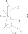
- FIG. 4A and FIG. 4Bshow schematic illustrations of embodiments of an expandable member 170.
- the head section 402is dome-shaped or rounded.
- the bulbous shape of the head 412has a diameter D1 that is larger than the diameter D2 of the shaft section of the implant.
- the diameter D1 of the head section 402is at least double the diameter D2 of the shaft section 404.
- the diameter D1 of the head section 402is at least triple the diameter D2 of the shaft section 404.
- the diameter D1 of the head section 402is 2.5 times, 3.5 times, 4 times, 5 times, 10 times or more larger than the diameter D2 of the shaft section 404.
- the head sectionmay be about 20 to 35 mm in diameter at a distal part of the implant (for example, anatomically the proximal head of the humerus), tapering in the frusto-conical shaft section to 10 to 15 mm.
- the shaft section 404is generally triangular or tapered.
- the shaft section 404is generally frusto-conical.
- the expandable member 170, including the head section 402 and the shaft section 404,may be formed as a single piece, or, alternatively, these sections can be mated to one another via a screwed-in section, a through hole, or any other suitable mechanism.
- the shaft section 404 of the expandable member 170can include a transition portion 404a extending from the head section 402 and an extension portion 404b extending distally from the head 412 from the tapered portion 404a into the intramedullary cavity.
- the transition portion 404acan be tapered or frusto-conical and the extension portion can be either uniform or tapered.
- the diameter D2 of the transition portion 404is substantially the same as the diameter D3 of the extension portion 404b.
- the diameter D2 of the transition portion 404ais 1.5 times, 2 times, 3 times or more larger than the diameter D3 of the extension portion 404b.
- the diameter D1 of the head section 402is at least double the diameter D3 of the extension portion 404b of the shaft section 404. In an embodiment, the diameter D1 of the head section 402 is at least triple the diameter D3 of the extension portion 404b of the shaft section 404. In various embodiments, the diameter D1 of the head section 402 is 2.5 times, 3.5 times, 4 times, 5 times, 10 times or more larger than the diameter D3 of the extension portion 404b of the shaft section 404.
- the expandable member 170can be round or oval for placement into the space 410 within the head 412 of the bone 414. It should be noted that the expandable member 170 may have any other shape suitable for placement into a head of a bone. Suitable additional shapes include, but are not limited to, a sphere, ovoid sphere, tapered cone, three-dimensional wedge whereby one axis is significantly wider than the other, with both tapering from a larger dimension to a smaller dimension, and similar. As discussed above, the expandable member 170 can be a tapered elongated shape such as an antegrade shape or a retrograde shape, as shown in FIG. 1B and FIG. 1C , respectively.
- the external surface of the expandable member 170is resilient and puncture resistant.
- the expandable member 170is manufactured from a non-compliant (non-stretch/non-expansion) conformable material including, but not limited to, urethane, polyethylene terephthalate (PET), nylon elastomer and other similar polymers.
- the expandable member 170is manufactured from a polyethylene terephthalate (PET).
- PETpolyethylene terephthalate
- the expandable member 170is manufactured from a radiolucent material, which permit x-rays to pass through the expandable member 170.
- the expandable member 170is manufactured from a radiolucent polyethylene terephthalate (PET).
- the expandable member 170is manufactured from a conformable compliant material that is limited in dimensional change by embedded fibers. In an embodiment, at least a portion of the external surface 174 of the expandable member 170 is substantially even and smooth. In an embodiment, at least a portion of the external surface of the expandable member 170 includes at least one textured element such as a bump, a ridge, a rib, an indentation or any other shape. In an embodiment, at least a portion of the external surface of the expandable member 170 protrudes out to form a textured element. In an embodiment, at least a portion of the external surface of the expandable member 170 invaginates to form a textured element.
- the textured elementincreases the friction and improves the grip and stability of the expandable member 170 after the expandable member 170 is inserted into the fracture location. In an embodiment, the textured element results in increased interdigitation of bone-device interface as compared to an expandable member without textured elements.
- the textured elementcan be convex in shape. In an embodiment, the textured element can be concave in shape. In an embodiment, the textured element can be circumferential around the width of the expandable member 170, either completely or partially.
- bone graft or bone graft substitutecan be used in conjunction with an expandable member 170 of the present disclosure.
- the bone graftis an allogeneic bone graft.
- the bone graftis an autologous bone graft.
- the bone graft substituteis a hydroxyapatite bone substitute.
- a bone graft or bone graft substituteis used to fill in any gaps that may exist, for example, between the external surface of the expandable member 170 and the surfaces of the bone fragments.
- a bone graft or bone graft substituteis used to fill any gaps that may exist, for example, between the textured element of the expandable member 170 and the surfaces of the bone fragments.
- the expandable member 170can include an external surface that may be coated with materials including, but not limited to, drugs (for example, antibiotics), proteins (for example, growth factors) or other natural or synthetic additives (for example, radiopaque or ultrasonically active materials).
- drugsfor example, antibiotics
- proteinsfor example, growth factors
- other natural or synthetic additivesfor example, radiopaque or ultrasonically active materials.
- drugsfor example, antibiotics
- proteinsfor example, growth factors
- other natural or synthetic additivesfor example, radiopaque or ultrasonically active materials.
- an infectionmay develop in a patient, requiring the patient to undergo antibiotic treatment.
- An antibiotic drugmay be added to the external surface of the expandable member 170 to prevent or combat a possible infection.
- Proteinssuch as, for example, bone morphogenic protein or other growth factors have been shown to induce the formation of cartilage and bone.
- a growth factormay be added to the external surface of the expandable member 170 to help induce the formation of new bone. Due to the lack of thermal e
- the expandable member 170does not have any valves.
- One benefit of not having valvesis that the expandable member 170 may be expanded or reduced in size as many times as necessary to assist in the fracture reduction and placement.
- Another benefit of the expandable member 170 not having valvesis the efficacy and safety of the system 100. Since there is no communication passage of light-sensitive liquid 165 to the body there cannot be any leakage of liquid 165 because all the liquid 165 is contained within the expandable member 170.
- a permanent sealis created between the expandable member 170 and the delivery catheter 150 that is both hardened and affixed prior to the delivery catheter 150 being removed.
- abrasively treating the external surface of the expandable member 170 for example, by chemical etching or air propelled abrasive mediaimproves the connection and adhesion between the external surface of the expandable member 170 and a bone surface.
- the surfacingsignificantly increases the amount of surface area that comes in contact with the bone which can result in a stronger grip.
- the expandable member 170can be infused with light-sensitive liquid 165 and the light-sensitive liquid 165 can be cured to form a photodynamic implant, the photodynamic implant may be separated from the delivery catheter 150.
- a separation area 142is located at the junction between the distal end of the cured expandable member 170 (or photodynamic implant) and the delivery catheter 150 to facilitate the release of the photodynamic implant from the delivery catheter 150.
- the separation area 142ensures that there are no leaks of reinforcing material from the elongated shaft of the delivery catheter and/or the photodynamic implant.
- the separation areaseals the photodynamic implant and removes the elongated shaft of the delivery catheter by making a break at a known or predetermined site (e.g., a separation area).
- the separation area 142may be various lengths and up to about an inch long.
- the separation area 142may also include a stress concentrator, such as a notch, groove, channel or similar structure that concentrates stress in the separation area 142.
- the stress concentratorcan also be an area of reduced radial cross section of cured light-sensitive liquid inside a contiguous cross sectional catheter to facilitate separating by the application of longitudinal force.
- the stress concentratoris designed to ensure that the photodynamic implant is separated from the delivery catheter 150 at the separation area 142.
- the photodynamic implantWhen tension is applied to the delivery catheter 150, the photodynamic implant separates from the shaft of the delivery catheter 150, substantially at the location of the stress concentrator. The tension creates a sufficient mechanical force to preferentially break the cured material and catheter composite and create a clean separation of the photodynamic implant/shaft interface.
- the photodynamic implantmay be separated from the delivery catheter 150 by any other suitable means including, but not limited to, radial twisting, shear impact, and cross-sectional cutting.
- the shape of the photodynamic implantcorresponds to the shape of the expandable member 170.
- the photodynamic implantcan be pear-shaped, oval, round, elongated, tapered, and the like. Modification of light-sensitive liquid 165 infusion allows a user to adjust the span or thickness of expandable member 170 to provide specific photodynamic implant size and shape to each subject.
- the photodynamic implantbest mirrors the size and shape of the area into which the expandable member 170 is implanted.
- the photodynamic implantis configured to be at least partially placed into a space within a head of a bone.
- the photodynamic implantis configured to be contained within a head of a bone.
- the photodynamic implantis configured such that a distal section of the implant extends for a length into the shaft of the bone.
- the photodynamic implant formed by infusing and curing the light sensitive liquid 165 into the expandable member 170is used for restructuring, aligning and/or stabilizing a bone.
- the expandable member 170can be infused with an amount of light-sensitive liquid 165 such that the final cured photodynamic implant has the size and shape to substantially return a broken head of a bone to its anatomical shape.
- the expandable member 170can be infused with an amount of light-sensitive liquid 165 such that the photodynamic implant has the size and shape such that a head of a bone can be restructured to a substantially original size and shape around the final cured photodynamic implant.
- the expandable member 170can be infused with an amount of light-sensitive liquid 165 such that the photodynamic implant facilitates a reduction of a fractured bone.
- the size and shape of the photodynamic implant 510attempts to maximize the surface contact area with the surrounding bone, minimizing specific points of concentrated pressure.
- the photodynamic implantmay be sufficiently designed to provide high compressive strength, thus minimizing deformation under dynamic loading conditions.
- the expandable memberis positioned and inflated to a size sufficient to provide maximum fill of the cavity of the bone, such as an intramedullary canal, at the region of the fracture or weakened bone.
- the expandable memberis inflated to any suitable size. In an embodiment, the expandable member is inflated up to about 20 mm in diameter.
- FIG. 5shows an embodiment of a photodynamic implant 510 that is designed to engage other bone fixation implants 520 including, but not limited to, bone screws, nails, pins and rods, among others.
- the bone fixation implantscan engage the final cured photodynamic implant at any user-selected location along the photodynamic implant.
- FIG. 5illustrates a plurality of bone fixation implants 520 engaged with the photodynamic implant 510 at user-selected locations 525.
- bone fragmentscan be secured in substantially original position by attaching the bone fragments to the final cured photodynamic implant with bone fixation implants.
- the photodynamic implant 510can be placed into a space within a head of a bone and one or more bone fixation implants can be inserted through the bone into the photodynamic implant 510 so as to fixate the head to the rest of the bone.
- the photodynamic implant 510may include one or more receptacles 530 for receiving standard metallic implants.
- the photodynamic implant 510may include one or more receptacles 530 to engage an intramedullary nail or rod 550.
- the nail or rod 550may be secured to the photodynamic implant 510 by any suitable means such as, for example, locking, snap-fit, friction fit or threading or similar.
- bone fixation implantsincluding, but not limited to, screws and other suitable mechanisms are anchored into the cured expandable member or the photodynamic implant at the surgeons desired locations based on the fracture pathology and not the location of pre-determined locking holes.
- the photodynamic implantare of a sufficiently large size to provide for a significant anchor and target above and below the fracture site for placement of multiple bone fixation implants including support cross-locking screws and any other suitable mechanisms.
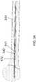
- FIG. 6illustrates a device inserted into a cavity of bone using the present systems and methods.
- a minimally invasive incision(not shown) is made through the skin of the patient's body to expose a fractured bone.
- the incisionmay be made at the proximal end or the distal end of the fractured bone to expose the bone surface. Once the bone is exposed, it may be necessary to retract some muscles and tissues that may be in view of the bone.
- an access hole 610is formed in a bone 605 by drilling or other methods known in the art. The access hole extends through a hard compact outer layer of the bone into the relatively porous inner or cancellous tissue.
- the medullary materialshould be cleared from the medullary cavity prior to insertion of the system 100.
- Marrowis found mainly in the flat bones such as hip bone, breast bone, skull, ribs, vertebrae and shoulder blades, and in the cancellous material at the proximal ends of the bones like the femur and humerus.
- the medullary materialincluding air, blood, fluids, fat, marrow, tissue and bone debris should be removed to form a void.
- the voidis defined as a hollowed out space, wherein a first position defines the most distal edge of the void with relation to the penetration point on the bone, and a second position defines the most proximal edge of the void with relation to the penetration site on the bone.
- the bonemay be hollowed out sufficiently to have the medullary material of the medullary cavity up to the cortical bone removed. Any suitable method for removing the medullary material may be used. Suitable methods include, but are not limited to, those described in U.S. Patent No. 4,294,251 entitled "Method of Suction Lavage," U.S. Patent No. 5,554,111 entitled “Bone Cleaning and Drying system," U.S. Patent No.
- a guidewire 608may be introduced into the bone 605 via the access hole 610 and advanced through the intramedullary cavity 615 of the bone 602 to a rounded head 609 of the bone 602.
- the expandable member 170 of the system 100is then delivered over the guidewire 608 to be placed within the head 609 of the bone 602.
- the location of the expandable member 170may be determined using at least one radiopaque marker 615 which is detectable from the outside or the inside of the bone 602.
- the light-sensitive liquid 165is then infused into the expandable member 170 to cause the expandable member 170 to expand to a desired size and shape, as described above.
- the light-sensitive liquid 165can be cured inside the expandable member 170 using the light-conducting fiber 140, as shown in FIG. 3A . After the light-sensitive liquid 165 is hardened, the light-conducting fiber 140 can be removed from the system 100.
- an expandable member 170is filled with the cured light-sensitive liquid 165 that is released from the delivery catheter 150 to form a photodynamic implant inside the head 609 of the bone 602, as shown in FIG. 3B .
- a photodynamic implant of the present disclosureacts to return a broken bone substantially to its original, anatomical shape.
- a photodynamic implant of the present disclosureacts as a mandrel over which fragments of a broken bone can be arranged to a substantially original position and to which the fragments can be attached by using bone fixation implants, including, but not limited to, bone screws, nails, pins and rods, among others.
- a bone fixation implantscan be placed into a photodynamic implant of the present disclosure at any user-selected location on the photodynamic implant.
- a photodynamic implant of the present disclosureis used for reattaching a bone fragment separated from a broken bone.
- a photodynamic implant of the present disclosureis used to re-align fragments of a broken bone.
- a photodynamic implant of the present disclosureprovides support and stability to a fractured bone during the natural healing process of the bone.
- a photodynamic implant of the present disclosurecan be used to stabilize or add strength to a weakened bone.
- the photodynamic implantprovides rotational stability by contouring to the cavity of the bone without the need for a significant number of locking screws or other bone fixation mechanisms, though such mechanisms may be used.
- the expandable memberis of a sufficient size to provide bending stability.
- a bone implant system 100 of the present disclosureis used to treat a fractured or weakened proximal humerus.
- proximal humeral fracturesare classified based on the number and type of major fragments.
- a two-part fractureis typically a humeral neck fracture, separating the head of the humerus from the shaft of the humerus.
- More complicated fracturesare three-part and four-part fractures.
- Three-part proximal humerus fracturescan involve, for example, separation of greater tuberosity and humeral neck.
- Four-part fracturestypically involve articular surface of the head and head splitting fractures.
- a photodynamic implant of the present disclosurecan be used to treat two-part, three-part, or four-part fractures of the proximal humerus.
- a photodynamic implant of the present disclosurecan be used to realign, restructure, stabilize or support the shaft of the humerus, greater tuberosity, humeral neck, articular surface of the head and head splitting fractures.
- a photodynamic implant of the present disclosurecan be used to stabilize a weakened humeral head, neck, shaft or other portions of humerus.
- access to the intramedullary cavity of a humeruscan be obtained by either retrograde approach or an antegrade approach as described above. It should be noted that the orientation of the expandable member relative to the delivery catheter will change depending on the chosen approach.
- the expandable member 107is placed within a space of cancellous bone near the top of the humeral head. Once the expandable portion 107 is in the correct position within the humerus, the expandable portion 107 is filled with the light-sensitive liquid 165, which is then cured resulting in the photodynamic implant 510.
- the bone implant system 100is used to treat a humeral neck fracture, separating the head of the humerus from the shaft of the humerus.
- the addition of the light-sensitive liquid 165 to the expandable member 170causes the expandable member to expand.
- the expandable member 170is expanded by the entering light-sensitive liquid 165, the fracture of the humeral neck is reduced.
- the light-sensitive liquid 165can be cured to form the photodynamic implant 510, which can then be separated from the delivery catheter.
- the photodynamic implant 510is used to treat a three-part fracture or a four-part fracture of a humeral head.
- the photodynamic implant 510acts as a filler, mandrel or support element for fragments of the humeral head.
- the photodynamic implant 510fills the space within the humeral head to substantially return the hemural head to its anatomical shape.
- fractured bone fragmentscan be placed over the photodynamic implant 510 to return the fragments to their respective substantially original, anatomical positions.
- broken fragmentscan be secured in their respective substantially, original position by attaching the broken fragments to the photodynamic implant by bone fixation implants, such as bone screws, nails, pins and rods, among others.
- the photodynamic implant 510extends into the shaft of the humerus or is attached to another implant that extends into the shaft of the humerus to provide additional stability to the bone for the duration of the healing process.
- a bone implant system 100 of the present disclosureis used to treat a proximal femoral fracture, such as a femoral neck fracture. In an embodiment, a bone implant system 100 of the present disclosure is used to treat or stabilize a weakened femoral head.
- the photodynamic implant 710is created inside an intramedullary space 704 within a head 706 of the femur 702, as described above.
- the broken fragments of the femur 702can then be aligned and compressed together by placing a metal screw 708 or another bone fixation implant through the bone fragments or the side of the femur 702 into the photodynamic implant 710 in the femoral head 706.
- the force of compression on the bone fragmentscan be controlled by controlling the distance to which the screw 708 is driven into the photodynamic implant 710.
- the combination of the photodynamic implant 710 and a secondary implant, i.e. the screw 708,provides strength and stability to the femur 702.
- the photodynamic implant 710can be configured to fill interstitial space between the bone fixation implant 708 and cortical bone surface inside the intramedullary cavity 704 to distribute load more evenly across the bone surface. That is, the photodynamic implant 710 acts as a filler between the bone fixation implant 708 and the cortical bone surface so that load is not transferred between the bone fixation implant 708 and the cortical bone through focal contact points between the bone fixation implant 708 and the cortical bone, but is rather distributed throughout a conformal contact created by the photodynamic implant 710.
- the present deviceincludes a series of small interlocking metallic or plastic tubes that are inserted into the cavity of the bone, such as the medullary canal.
- the series of tubesare used instead of or in addition to the use of the catheter
- the tubesare made from any suitable material including, but not limited to, a metal or a plastic.
- the tubesare interlocked sequentially to adjacent tubes such that the addition of the each incremental tube lengthens the entire tube.
- the tubesare slid over a mandrel and then locked or engaged to an adjacent tube in an end to end fashion.
- the interlocking mechanism of the sequential tubesis flexible so that the tubes can accommodate curvatures and deflections within the cavity of the bone. Since the series of tubes are flexible, the series of tubes are able to transit the length of the cavity of the bone without being obstructed within the canal as would a rigid length of tubing. Also, because the tube is flexible, a larger diameter tube or series of tubes may be interlocked and used within the cavity of a bone. A rigid tube would need to have a smaller diameter to navigate the deflections and curvatures within a cavity of a bone.
- the interlocking tubesmay be of different diameters such that the tubes can accommodate different diameters and tapers within the cavity of the bone.
- the photodynamic monomer and the expandable memberare inserted into and through the tube, the expandable member is inflated, and the photodynamic monomer is cured within the confines of the tube.
- the use of the series of tubes and the monomer disposed within the series of tubesprovides a stronger photodynamic implant.
- a device for restructuring or stabilizing a fractured or weakened head of a boneincludes a delivery catheter having an elongated shaft with a proximal end, a distal end, and a longitudinal axis therebetween, the delivery catheter having an inner void for passing at least one light sensitive liquid, and an inner lumen; an expandable member releasably engaging the distal end of the delivery catheter, the expandable member moving from a deflated state to an inflated state when the at least one light sensitive liquid is passed to the expandable member; wherein the expandable member is sufficiently designed to be at least partially placed into a space within a head of a bone, and a light conducting fiber sized to pass through the inner lumen of the delivery catheter and into the expandable member, wherein, when the light conducting fiber is in the expandable member, the light conducting fiber is able to disperse the light energy to initiate hardening of the at least one light sensitive liquid within the expandable member to form a photodynamic implant.
- a method for repairing or stabilizing a fractured or weakened head of a boneincludes placing a expandable member removably attached to a distal end of a delivery catheter into at least partially into a space within a head of a bone, infusing a light sensitive liquid into the expandable member through an inner lumen of the delivery catheter, inserting a light conducting fiber into the expandable member through an inner void of the delivery catheter, and activating the light conducting fiber to cure the light sensitive liquid inside the expandable member, thereby forming a photodynamic implant inside the head of the bone which serves as a mandrel or form for repair and stabilization of the head of the bone.
- a kit for repairing or stabilizing a fractured or weakened head of a boneincludes an light conducting fiber; a unit dose of at least one light sensitive liquid; and a delivery catheter having an elongated shaft with a proximal end, a distal end, and a longitudinal axis therebetween, wherein the delivery catheter has an inner void for passing the at least one light sensitive liquid into a expandable member releasably engaging the distal end of the delivery catheter, and an inner lumen for passing the light conducting fiber into the expandable member, wherein the expandable member is sufficiently designed to be at least partially placed into a space within a head of a bone.
- the kitincludes a plurality of expandable members of different sizes or shapes.
- the kitincludes a light source.
- a device for restructuring or stabilizing a fractured or weakened head of a boneincludes: a delivery catheter having an elongated shaft with a proximal end, a distal end, and a longitudinal axis therebetween, an inner void for passing at least one light sensitive liquid, and an inner lumen; an expandable member releasably engaging the distal end of the delivery catheter; and a light conducting fiber sized to pass through the inner lumen of the delivery catheter and into the expandable member.
- the expandable memberis capable of moving from a deflated state to an inflated state when the at least one light sensitive liquid is passed to the expandable member.
- the expandable memberis sufficiently designed to be at least partially placed into a space within a head of a bone. When the light conducting fiber is in the expandable member, the light conducting fiber is able to disperse the light energy to initiate hardening of the at least one light sensitive liquid within the expandable member to form a photodynamic implant
- a method for repairing or stabilizing a fractured or weakened head of a boneincludes: placing an expandable member removably attached to a distal end of a delivery catheter at least partially into a space within a head of a bone; infusing a light sensitive liquid into the expandable member through an inner lumen of the delivery catheter; inserting a light conducting fiber into the expandable member through an inner void of the delivery catheter; and activating the light conducting fiber to cure the light sensitive liquid inside the expandable member to form a photodynamic implant inside the head of the bone.
- the expandable memberhas a tapered elongated shape.
- a kit for repairing or stabilizing a fractured or weakened head of a boneincludes: a light conducting fiber; at least one light sensitive liquid; a delivery catheter having an elongated shaft with a proximal end, a distal end, and a longitudinal axis therebetween, an inner void, and an inner lumen; and an expandable member releasably engaging the distal end of the delivery catheter.
- the expandable memberis sufficiently designed to be at least partially placed into a space within a head of a bone.
- the delivery catheterhas an inner void for passing the at least one light sensitive liquid into the expandable member, and an inner lumen for passing the light conducting fiber into the expandable member.
- the kitsincludes a plurality of expandable members of different sizes or shapes.
- the kitincludes a light source.
Landscapes
- Health & Medical Sciences (AREA)
- Orthopedic Medicine & Surgery (AREA)
- Life Sciences & Earth Sciences (AREA)
- Surgery (AREA)
- Engineering & Computer Science (AREA)
- Biomedical Technology (AREA)
- General Health & Medical Sciences (AREA)
- Animal Behavior & Ethology (AREA)
- Public Health (AREA)
- Veterinary Medicine (AREA)
- Nuclear Medicine, Radiotherapy & Molecular Imaging (AREA)
- Heart & Thoracic Surgery (AREA)
- Medical Informatics (AREA)
- Molecular Biology (AREA)
- Neurology (AREA)
- Radiology & Medical Imaging (AREA)
- Pathology (AREA)
- Oral & Maxillofacial Surgery (AREA)
- Cardiology (AREA)
- Transplantation (AREA)
- Vascular Medicine (AREA)
- Biophysics (AREA)
- Physical Education & Sports Medicine (AREA)
- Prostheses (AREA)
- Surgical Instruments (AREA)
- Materials For Medical Uses (AREA)
Description
- The embodiments disclosed herein relate to bone implants, and more particularly to devices and methods for bone restructure and stabilization.
- Bones form the skeleton of the body and allow the body to be supported against gravity and to move and function in the world. Bone fractures can occur, for example, from an outside force or from a controlled surgical cut (an osteotomy). A fracture's alignment is described as to whether the fracture fragments are displaced or in their normal anatomic position. In some instances, surgery may be required to re-align and stabilize the fractured bone. But proper positioning and alignment of a bone is difficult to achieve. It would be desirable to have an improved device or method for stabilizing, positioning, and repairing a fractured or weakened bone.
US 2010/0262069 discloses a photodynamic bone stabilisation system which is not adapted for use in a bone head and which does not include a receptacle to engage an intramedullary rod.- Devices and methods for bone restructure and stabilization are disclosed herein. According to aspects illustrated herein, there is provided a device for repairing or stabilizing a fractured or weakened head of a bone that includes a delivery catheter having an elongated shaft with a proximal end, a distal end, and a longitudinal axis therebetween, the delivery catheter having an inner void for passing at least one light sensitive liquid, and an inner lumen; an expandable member releasably engaging the distal end of the delivery catheter, the expandable member moving from a deflated state to an inflated state when the at least one light sensitive liquid is passed to the expandable member, wherein the expandable member is sufficiently designed to be at least partially placed into a space within a head of a bone; and a light conducting fiber sized to pass through the inner lumen of the delivery catheter and into the expandable member, wherein, when the light conducting fiber is in the expandable member, the light conducting fiber is able to disperse the light energy to initiate hardening of the at least one light sensitive liquid within the expandable member, forming a photodynamic implant of the present disclosure. In an embodiment, the expandable member is sufficiently designed to be contained within a head of a bone. In an embodiment, the expandable member is sufficiently designed such that a head section of the expandable member is within a head of a bone and a shaft section of the expandable member extends for a length into the shaft of the bone.
- In an embodiment, a photodynamic implant of the present disclosure acts as a mandrel or form over which fragments of a head of a bone can be arranged to a substantially original position. In an embodiment, a photodynamic implant acts as a filler to return a head of a bone substantially to its original, anatomical shape prior to fracture or breaking. In an embodiment, a photodynamic implant of the present disclosure is used for reattaching bone fragments of a head of a bone separated from the bone. In an embodiment, a photodynamic implant of the present disclosure is used for fixating a head of a bone separated from the bone. In an embodiment, a photodynamic implant of the present disclosure is used to re-align fragments of a broken bone to promote fracture restructure and stabilization. In an embodiment, a photodynamic implant of the present disclosure provides support and stability to a fractured or weakened bone during the natural healing process of the bone. In an embodiment, a photodynamic implant of the present disclosure is used to provide added strength to a weakened bone.
- In an embodiment, a photodynamic implant of the present disclosure is configured to engage with another implant, including, but not limited to, a metal screw, rod, pin or nail. In an embodiment, a photodynamic implant of the present disclosure provides means to secure, bolt and pull the fractured bone segments back together into position. In an embodiment, a photodynamic implant of the present disclosure is used to fill a space within a fractured bone to return the fractured bone to its anatomical shape and is engaged to another implant that provides strength and stability to the shape. In an embodiment, a photodynamic implant of the present disclosure is configured to receive bone screws such that compressive force is exerted on bone fragments supported by the photodynamic implant.
- In an embodiment, a photodynamic implant of the present disclosure is configured to fill interstitial space between a bone fixation implant and cortical bone to distribute load more evenly across the bone interface. That is, a photodynamic implant of the present disclosure acts as a filler between a bone fixation implant and a cortical bone interface so that load is not transferred through focal contact points between the bone fixation device and the cortical bone, but rather the load is distributed throughout a conformal contact in the bone. According to the invention, a device for restructuring or stabilizing a fractured or weakened head of a bone is provided. The device includes: a delivery catheter having an elongated shaft with a proximal end, a distal end, and a longitudinal axis therebetween, an inner void for passing at least one light sensitive liquid, and an inner lumen; an expandable member releasably engaging the distal end of the delivery catheter; and a light conducting fiber sized to pass through the inner lumen of the delivery catheter and into the expandable member. The expandable member is capable of moving from a deflated state to an inflated state when the at least one light sensitive liquid is passed to the expandable member. The expandable member is sufficiently designed to be at least partially placed into a space within a head of a bone. When the light conducting fiber is in the expandable member, the light conducting fiber is able to disperse the light energy to initiate hardening of the at least one light sensitive liquid within the expandable member to form a photodynamic implant
- In an embodiment, the expandable member has a pear shape, bulb shape, dome shape, rounded shape, or elongated shape. In an embodiment, the expandable member has a tapered elongated shape. In an embodiment, the expandable member has a retrograde shape or an antegrade shape. In an embodiment, the expandable member has a proximal end and a distal end, and the diameter of the proximal end of the expandable member is larger than the diameter of the distal end of the expandable member. In an embodiment, the expandable member has a proximal end and a distal end, and the diameter of the distal end of the expandable member is larger than the diameter of the proximal end of the expandable member. In an embodiment, the expandable member is sufficiently designed to be contained within a head of a bone. In an embodiment, the expandable member includes a head section and a shaft section, and the expandable member is sufficiently designed such that the head section can be placed within a head of a bone and the shaft section can extend for a length into a shaft of the bone. According to the invention, the photodynamic implant is configured to engage with at least one bone fixation implant such as a intramedullary nail or rod. In an embodiment, the light conducting fiber includes a core and a cladding disposed on the core, and the cladding has at least one cut therein to expose the core and configured to alter the light exuded from the light conducting fiber.
- In one aspect, a kit for repairing or stabilizing a fractured or weakened head of a bone includes: a light conducting fiber; at least one light sensitive liquid; a delivery catheter having an elongated shaft with a proximal end, a distal end, and a longitudinal axis therebetween, an inner void, and an inner lumen; and an expandable member releasably engaging the distal end of the delivery catheter. The expandable member is sufficiently designed to be at least partially placed into a space within a head of a bone. The delivery catheter has an inner void for passing the at least one light sensitive liquid into the expandable member, and an inner lumen for passing the light conducting fiber into the expandable member. In an embodiment, the kits includes a plurality of expandable members of different sizes or shapes. In an embodiment, the kit includes a light source.
- In an example, a method for repairing or stabilizing a fractured or weakened head of a bone includes: placing an expandable member removably attached to a distal end of a delivery catheter at least partially into a space within a head of a bone; infusing a light sensitive liquid into the expandable member through an inner lumen of the delivery catheter; inserting a light conducting fiber into the expandable member through an inner void of the delivery catheter; and activating the light conducting fiber to cure the light sensitive liquid inside the expandable member to form a photodynamic implant inside the head of the bone. In an embodiment, the expandable member has a tapered elongated shape.
- In an embodiment, the method includes disposing a head section of the expandable member within a head of a bone and extending a shaft section of the expandable member for a length into the shaft of the bone. In an embodiment, the method includes engaging the photodynamic implant with at least one bone fixation implant. In an embodiment, the at least one bone fixation implant is a screw, rod, pin, nail, or combination thereof. In an embodiment, the bone is a femur or a humerus.
- The presently disclosed embodiments will be further explained with reference to the attached drawings, wherein like structures are referred to by like numerals throughout the several views. The drawings shown are not necessarily to scale, with emphasis instead generally being placed upon illustrating the principles of the presently disclosed embodiments.
FIG. 1A shows a schematic illustration of an embodiment of a bone implant system of the present disclosure. The system includes a light source, a light pipe, an attachment system, a light-conducting fiber, a light-sensitive liquid, a delivery catheter and an expandable member sufficiently shaped to fit within a space or a gap in a fractured bone.FIG. 1B and FIG. 1C show schematic illustrations of embodiments of a bone implant device that includes a delivery catheter and an expandable member sufficiently shaped to fit within a space or a gap in a fractured bone.FIG. 2A and FIG. 2B show close-up cross-sectional views of the region circled inFIG. 1A .FIG. 2A shows a cross-sectional view of a distal end of the delivery catheter and the expandable member prior to the device being infused with light-sensitive liquid.FIG. 2B shows a cross-sectional view of the distal end of the delivery catheter and the expandable member after the device has been infused with light-sensitive liquid and light energy from the light-conducting fiber is introduced into the delivery catheter and inner lumen of the expandable member to cure the light-sensitive liquid.FIG. 2C and FIG. 2D show a close-up cross-sectional view of the regions circled inFIG. 1B and FIG. 1C , respectively.FIG. 2C and FIG. 2D show a cross-sectional view of a distal end of the delivery catheter and the expandable member and a light-conducting fiber in the delivery catheter and inner lumen of the expandable member.FIG. 3A illustrates a cross-section view of an embodiment of a device in a cavity of a bone prior to inflation of the expandable member.FIG. 3B illustrates a cross-section view of an embodiment of a device in a cavity of a bone after inflation of the expandable member.FIG. 4A andFIG. 4B show schematic illustrations of embodiments of an expandable member.FIG. 5 is a schematic illustration of an embodiment of a photodynamic implant of the present disclosure.FIG. 6 illustrates a cross-sectional view of an embodiment of a device being inserted into a cavity of bone using the disclosed devices and methods.FIG. 7 shows a cross-sectional view of an embodiment of a device for treating a fractured or weakened head of a femur using the disclosed methods.- While the above-identified drawings set forth presently disclosed embodiments, other embodiments are also contemplated, as noted in the discussion. This disclosure presents illustrative embodiments by way of representation and not limitation. Numerous other modifications and embodiments can be devised by those skilled in the art which fall within the scope and spirit of the principles of the presently disclosed embodiments.
- Devices and methods for bone restructure and stabilization are disclosed herein. In an embodiment, the present disclosure is directed to devices and methods for human treatment of bone fractures. In an embodiment, the present disclosure is directed to devices and methods for veterinary treatment of a fractured or a weakened bone. In an embodiment, devices and methods are provided for restructure, alignment and stabilization of a bone having a rounded head. The devices of the present disclosure are suitable to treat any fractured or weakened bone including, but not limited to, tibia, femur, fibula, humerus, ulna, radius, metatarsals, metacarpals, phalanx, phalanges, ribs, spine, vertebrae, clavicle, pelvis, wrist, mandible, and other bones. In an embodiment, a bone implant system of the present disclosure is used to treat a fractured or weakened proximal humerus. In an embodiment, a bone implant system of the present disclosure is used to treat a fractured or weakened femoral head.
- As used herein, the terms "fracture" or "fractured bone" refer to a partial or complete break in the continuity of a bone. The fracture can occur, for example, from an outside force or from a controlled surgical cut (osteotomy). The presently disclosed embodiments can be used to treat any type of bone fracture, including, but not limited to, a displaced fracture, a non-displaced fracture, an open fracture, a closed fracture, a hairline fracture, a compound fracture, a simple fracture, a multi-fragment fracture, a comminuted fracture, an avulsion fracture, a buckle fracture, a compacted fracture, a stress fracture, a compression fracture, spiral fracture, butterfly fracture, other fractures as described by AO Foundation coding, multiple fractures in a bone, and other types of fractures.
- As used herein, the term "weakened bone" refers to a bone with a propensity toward a fracture due to a decreased strength or stability due to a disease or trauma. Some bone diseases that weaken the bones include, but are not limited to, osteoporosis, achondroplasia, bone cancer, fibrodysplasia ossificans progressiva, fibrous dysplasia, legg calve perthes disease, myeloma, osteogenesis imperfecta, osteomyelitis, osteopenia, osteoporosis, Paget's disease, and scoliosis. Weakened bones are more susceptible to fracture, and treatment to prevent bone fractures may be desirable.
- As used herein, the term "photodynamic implant" refers to an expandable member of the present disclosure that is infused with a photodynamic (light curable) material and exposed to an appropriate frequency of light and intensity to cure the material inside the expandable member and form a rigid structure.
- As used herein, the terms "bone restructuring" or "restructure" refer to positioning a fractured bone back to a substantially normal, anatomically-correct position (separation of the bone fragments) and/or shape as well as supporting or stabilizing a weakened bone. In an embodiment, a photodynamic implant of the present disclosure provides a template, mandrel or form for restructuring a fractured or weakened bone. That is, a photodynamic implant of the present disclosure acts as a template, mandrel or form over which the fragments of a fractured bone can be arranged to a substantially original position and/or to which the fragments can be secured in a substantially original position. In an embodiment, a photodynamic implant of the present disclosure acts as a template, mandrel or form to return a broken bone to its a substantially normal, anatomically-correct shape. In an embodiment, a photodynamic implant of the present disclosure acts as a template, mandrel or form to support or stabilize a weakened bone in its a substantially normal, anatomically-correct shape. In an embodiment, a photodynamic implant of the present disclosure is used to restructure a fractured bone by aiding in attachment of a broken-off portion of a bone to the intact portion of the bone. In an embodiment, a photodynamic implant of the present disclosure is used to add strength to a weakened bone to prevent further weakening or a potential fracture.
- In an embodiment, the present device is used in a minimally invasive surgical procedure. The device can enter a minimally invasive incision or access hole of any suitable size. For example, the access hole is about 5mm to about 6mm in diameter or any other suitable dimensions. In an embodiment, an expanding reamer or burr is used to pass through the small access hole. When inserted, the reamer is opened up to create a larger hole in the bone.
FIG. 1A shows a schematic illustration of an embodiment of abone implant system 100. As shown inFIG. 1A , thesystem 100 includes alight source 110, alight pipe 120, anattachment system 130 and a light-conductingfiber 140. Theattachment system 130 communicates light energy from thelight source 110 to the light-conductingfiber 140. In an embodiment, thelight source 110 emits frequency that corresponds to a band in the vicinity of 390 nm to 770 nm, the visible spectrum. In an embodiment, thelight source 110 emits frequency that corresponds to a band in the vicinity of 410 nm to 500 nm. In an embodiment, thelight source 110 emits frequency that corresponds to a band in the vicinity of 430 nm to 450 nm. Thesystem 100 further includes aflexible delivery catheter 150 having a proximal end that includes at least two ports and a distal end terminating in anexpandable member 170. Theexpandable member 170 ofFIG. 1A has a bulbous shape, but may have any other suitable shape.FIG. 1B and FIG. 1C show schematic illustrations of embodiments of a bone implant device. The devices include adelivery catheter 150 and anexpandable member 170 sufficiently shaped to fit within a space or a gap in a fractured bone. Theexpandable members 170 ofFIG. 1B and FIG. 1C have a tapered elongated shape to fill the space or gap in certain fractured or weakened bones to be repaired or stabilized. In an embodiment, theexpandable member 170 has an antegrade shape as shown inFIG. 1B . In an embodiment, theexpandable member 170 has a retrograde shape as shown inFIG. 1C . InFIG. 1B , theexpandable member 170 has a larger diameter at its distal end than the proximal end. InFIG. 1C , theexpandable member 170 has a larger diameter at its proximal end than the distal end.- In an embodiment, the maximum diameter of the larger portion of the
expandable member 170 is at least 1.5 times larger than the maximum diameter of the smaller portion of theexpandable member 170. In an embodiment, the maximum diameter of the larger portion of theexpandable member 170 is at least two times larger than the maximum diameter of the smaller portion of theexpandable member 170. - In an embodiment, shown in
FIG. 1B , the maximum diameter of the proximal portion of theexpandable member 170 is at least 1.5 times the maximum diameter of the distal portion of theexpandable member 170. In an embodiment, the maximum diameter of the proximal portion of theexpandable member 170 is at least two times the maximum diameter of the distal portion of theexpandable member 170. - In an embodiment, shown in
FIG. 1C , the maximum diameter of the distal portion of theexpandable member 170 is at least 1.5 times the maximum diameter of the proximal portion of theexpandable member 170. In an embodiment, the maximum diameter of the distal portion of theexpandable member 170 is at least two times the maximum diameter of the proximal portion of theexpandable member 170. - The various shapes of the
expandable member 170 allow for different approaches during minimally invasive surgical treatment of weakened or fractured bones. For example, anexpandable member 170 having a retrograde or antegrade shape can be used for repair of a weakened or fractured proximal humerus. The antegrade shape allows for placement of the portion of theexpandable member 170 with the largest diameter at the bone location most in need of repair or stabilization, including above and below the surgical neck area. For example, in the case of a proximal humerus, the antegrade shape allows for an incision and entry point into the humeral head through or just lateral to the rotator cuff. The geometry of the retrograde shape is opposite to the antegrade shape. With the retrograde shape, the portion of theexpandable member 170 with the largest diameter is placed at the distal end of thecatheter 150. The retrograde shapedexpandable member 170 having the largest diameter can be placed at the bone location most in need of repair or stabilization, including above and below the surgical neck area. When repairing a proximal humerus, the retrograde shape allows for distal placement through an incision and bone entry point at (1) the medial or lateral epicondyles or (2) between these condyles at the roof of the olecranon fossa. In an embodiment, a device includes a retrograde shapeexpandable member 170 and has a longer catheter 150 (for example, about 3-4 inches longer) due to the increased distance from the bone access hole to the surgical neck. - In an embodiment, the
expandable member 170 is sufficiently shaped to fit within a space or a gap in a fractured or weakened bone. One or more radiopaque markers, bands or beads may be placed at various locations along theexpandable member 170 and/or theflexible delivery catheter 150 so that components of thesystem 100 may be viewed using fluoroscopy. - In the embodiments shown in
FIG. 1A ,FIG. 1B, and FIG. 1C , the proximal end of thedelivery catheter 150 includes afirst port 162 and asecond port 164. Thefirst port 162 can accept, for example, the light-conductingfiber 140. Thesecond port 164 can accept, for example, a syringe 160 housing a light-sensitive liquid 165. In an embodiment, the syringe 160 maintains a low pressure during the infusion and aspiration of the light-sensitive liquid 165. In an embodiment, the syringe 160 maintains a low pressure of about 10 atmospheres or less during the infusion and aspiration of the light-sensitive liquid 165. In an embodiment, the syringe 160 maintains a low pressure of less than about 5 atmospheres during the infusion and aspiration of the light-sensitive liquid 165. In an embodiment, the syringe 160 maintains a low pressure of about 4 atmospheres or less during the infusion and aspiration of the light-sensitive liquid 165. In an embodiment, the light-sensitive liquid 165 is a photodynamic (light-curable) monomer. In an embodiment, the photodynamic (light-curable) monomer is exposed to an appropriate frequency of light and intensity to cure the monomer inside theexpandable member 170 and form a rigid structure. In an embodiment, the photodynamic (light-curable)monomer 165 is exposed to electromagnetic spectrum that is visible (frequency that corresponds to a band in the vicinity of 390 nm to 770 nm). In an embodiment, the photodynamic (light-curable)monomer 165 is radiolucent, which permit x-rays to pass through the photodynamic (light-curable)monomer 165. In an embodiment, thedelivery catheter 150 has one or more ports. FIG. 2A and FIG. 2B show close-up cross-sectional views of the region circled inFIG. 1 .FIG. 2A shows a cross-sectional view of a distal end of thedelivery catheter 150 and theexpandable member 170 prior to the device being infused with light-sensitive liquid.FIG. 2B shows a cross-sectional view of the distal end of thedelivery catheter 150 and theexpandable member 170 after the device has been infused with light-sensitive liquid and light energy from the light-conducting fiber is introduced into thedelivery catheter 150 and inner lumen of theexpandable member 170 to cure the light-sensitive liquid.- As illustrated in
FIG. 2A and FIG. 2B , theflexible delivery catheter 150 includes aninner void 152 for passage of the light-sensitive liquid 165, and aninner lumen 154 for passage of the light-conductingfiber 140. In the embodiment illustrated inFIG. 2A and FIG. 2B , theinner lumen 154 and theinner void 152 are concentric to one another. The light-sensitive liquid 165 has a low viscosity or low resistance to flow, to facilitate the delivery of the light-sensitive liquid 165 through theinner void 152. In an embodiment, the light-sensitive liquid 165 has a viscosity of about 1000 cP or less. In an embodiment, the light-sensitive liquid 165 has a viscosity ranging from about 650 cP to about 450 cP. Theexpandable member 170 may be inflated, trial fit and adjusted as many times as a user wants with the light-sensitive liquid 165, up until thelight source 110 is activated, when the polymerization process is initiated. Because the light-sensitive liquid 165 has a liquid consistency and is viscous, the light-sensitive liquid 165 may be delivered using low pressure delivery and high pressure delivery is not required, but may be used. FIG. 2C and FIG. 2D show a close-up cross-sectional view of the region circled inFIG. 1B and FIG. 1C , respectively.FIG. 2C and FIG. 2D show cross-sectional views of a distal end of thedelivery catheter 150 and theexpandable member 170 and a light-conductingfiber 140 in thedelivery catheter 150 and inner lumen of theexpandable member 170. The device also has aseparation area 172 at the junction of thedelivery catheter 150 and theexpandable member 170 where thedelivery catheter 150 may be separated from theexpandable member 170.- In an embodiment, a contrast material may be added to the light-
sensitive liquid 165 without significantly increasing the viscosity. Contrast materials include, but are not limited to, barium sulfate, tantalum, or other contrast materials known in the art. The light-sensitive liquid 165 can be introduced into the proximal end of theflexible delivery catheter 150 and passes within theinner void 152 of theflexible delivery catheter 150 up into aninner cavity 172 of theexpandable member 170 to change a thickness of theexpandable member 170 without changing a width or depth of theexpandable member 170. In an embodiment, the light-sensitive liquid 165 is delivered under low pressure via the syringe 160 attached to thesecond port 164. The light-sensitive liquid 165 can be aspirated and reinfused as necessary, allowing for thickness adjustments to theexpandable member 170 prior to activating thelight source 110 and converting theliquid monomer 165 into a hard polymer. - In an embodiment, the light-sensitive liquid may be provided as a unit dose. As used herein, the term "unit dose" is intended to mean an effective amount of light sensitive liquid adequate for a single session or treatment. By way of a non-limiting example, a unit dose of a light sensitive liquid of the present disclosure for expanding the
expandable member 170 may be defined as enough light-sensitive liquid to expand theexpandable member 170 to a desired shape and size. In an embodiment, theexpandable member 170 is sufficiently shaped and sized to fit within a space or a gap in a fractured bone. The desired shape and size of theexpandable member 170 may vary somewhat from patient to patient. Thus, a user using a unit dose may have excess light-sensitive liquid left over after the procedure. It is desirable to provide sufficient amount of light-sensitive liquid to accommodate even the above-average patient. In an embodiment, a unit dose of a light-sensitive liquid of the present disclosure is contained within a container. - In an embodiment, a unit dose of a light-sensitive liquid of the present disclosure is contained in an ampoule. In an embodiment, the light-sensitive liquid can be delivered under low pressure via a standard syringe attached to the
second port 164. In an embodiment, the light-sensitive liquid can be delivered without use of a pump. - As illustrated in
FIG. 1A in conjunction withFIG. 2B , the light-conductingfiber 140 can be introduced into the proximal end of theflexible delivery catheter 150 via thefirst port 162 and passes within theinner lumen 154 of theflexible delivery catheter 150 up into theexpandable member 170. The light-conductingfiber 140 is used in accordance to communicate energy in the form of light from thelight source 110 to a remote location. The light-sensitive liquid 165 remains a liquid monomer until activated by the light-conducting fiber 140 (cures on demand). Radiant energy from thelight source 110 is absorbed and converted to chemical energy to polymerize the monomer. The light-sensitive liquid 165, once exposed to the correct frequency light and intensity, is converted into a hard polymer, resulting in a rigid structure or photodynamic implant of the present disclosure. The monomer may cure in any amount of time. In an embodiment, the monomer in the lightsensitive liquid 165 cures in about five seconds to about five minutes. This cure affixes theexpandable member 170 in an expanded shape to form a photodynamic implant of the present disclosure. A cure may refer to any chemical, physical, and/or mechanical transformation that allows a composition to progress from a form (e.g., flowable form) that allows it to be delivered through theinner void 162 in theflexible delivery catheter 150, into a more permanent (e.g., cured) form for final usein vivo. For example, "curable" may refer to uncured light-sensitive liquid 165, having the potential to be curedin vivo (as by catalysis or the application of a suitable energy source), as well as to a light-sensitive liquid 165 in the process of curing (e.g., a composition formed at the time of delivery by the concurrent mixing of a plurality of composition components). - Light-conducting fibers use a construction of concentric layers for optical and mechanical advantages. Suitable light-conducting
fiber 140 can be made from any material, including, but not limited to, glass, silicon, silica glass, quartz, sapphire, plastic, combinations of materials, or any other material, and may have any diameter. In an embodiment, the light-conducting fiber may be made from a polymethyl methacrylate core with a transparent polymer cladding. The light-conductingfiber 140 has any suitable diameter. In an embodiment, the light-conducting fiber has a diameter between approximately 0.75 mm and approximately 2.0 mm. In some embodiments, the light-conducting fiber can have a diameter of about 0.75 mm, about 1 mm, about 1.5 mm, about 2 mm, less than about 0.75 mm or greater than about 2 mm. - In an embodiment, one or more
light conducting fibers 140 are used. Using more than onelight conducting fibers 140 may reduce the cure time of the light-sensitive liquid, particularly when used with largerexpandable members 170. In an embodiment, a plurality oflight conducting fibers 140 are positioned side-by-side or in parallel in theexpandable member 170. In an embodiment, a plurality oflight conducting fibers 140 are positioned serially with ends of adjacentlight conducting fibers 140 aligned or abutting on another in an end to end fashion. For example, one light conducting fiber may be positioned in the distal portion of the expandable member and another light conducting fiber may be positioned in the proximal portion of theexpandable member 170. In an embodiment, a plurality of light conducting fibers are positioned in a combination of parallel and serial positions, such as partially overlapping or any other suitable configuration. In an embodiment, a plurality of light conducting fibers can be attached to a single light source with a splitter, or can be attached to a plurality of light sources. - In an embodiment, when a plurality of
light conducting fibers 140 are used, an inner lumen of adelivery catheter 150 has a larger inner diameter. In an embodiment, an inner lumen of thedelivery catheter 150 has an inner diameter of about 1.8 mm. In an embodiment, an inner lumen of the delivery catheter is sized to contain a plurality oflight conducting fibers 140. In an embodiment, a delivery catheter sized to contain a plurality oflight conducting fibers 140 has an inner diameter of about 2.3 mm to about 3.0 mm. - In an embodiment, the light-conducting
fiber 140 is made from a polymethyl methacrylate core with a transparent polymer cladding. It should be appreciated that the above-described characteristics and properties of the light-conductingfibers 140 are exemplary and not all embodiments of the present disclosure are intended to be limited in these respects. Light energy from a visible emitting light source can be transmitted by the light-conductingfiber 140. In an embodiment, visible light having a wavelength spectrum of between about 380 nm to about 780 nm, between about 400 nm to about 600 nm, between about 420 nm to about 500 nm, between about 430 nm to about 440 nm or any other suitable wavelengths, is used to cure the light-sensitive liquid. - The most basic function of a fiber is to guide light, i.e., to keep light concentrated over longer propagation distances despite the natural tendency of light beams to diverge, and possibly even under conditions of strong bending. In the simple case of a step-index fiber, this guidance is achieved by creating a region with increased refractive index around the fiber axis, called the fiber core, which is surrounded by the cladding. The cladding may be protected with a polymer coating. Light is kept in the "core" of the light-conducting fiber by total internal reflection. Cladding keeps light traveling down the length of the fiber to a destination. In some instances, it is desirable to conduct electromagnetic waves along a single guide and extract light along a given length of the guide's distal end rather than only at the guide's terminating face.
- In some embodiments of the present disclosure, at least a portion of a length of a light-conducting fiber is modified, e.g., by removing the cladding, in order to alter the profile of light exuded from the light-conducting fiber. The term "profile of light" refers to, without limitation, direction, propagation, amount, intensity, angle of incidence, uniformity, distribution of light and combinations thereof. In an embodiment, the light-conducting fiber emits light radially in a uniform manner, such as, for example, with uniform intensity, along a length of the light-conducting fiber in addition to or instead of emitting light from its terminal end/tip. To that end, all or part of the cladding along the length of the light-conducting fiber may be removed. It should be noted that the term "removing cladding" includes taking away the cladding entirely to expose the light-conducting fiber as well as reducing the thickness of the cladding. In addition, the term "removing cladding" includes forming an opening, such as a cut, a notch, or a hole, through the cladding. In an embodiment, removing all or part of the cladding may alter the propagation of light along the light-conducting fiber. In another embodiment, removing all or part of the cladding may alter the direction and angle of incidence of light exuded from the light-conducting fiber.
FIG. 1B, FIG. 1C ,FIG. 2C, and FIG. 2D show an example of a light-conducting fiber having acut 141 in the cladding along the length of the light-conducting fiber to modify light exuding from the light-conducting fiber.FIG. 3A illustrates an embodiment of a device in a cavity of abone 314 prior to inflation of theexpandable member 170. In an embodiment, as shown inFIG. 3A , the cladding of the light-conductingfiber 140 is removed by making acut 141 in the cladding to expose the core of the light-conductingfiber 140. In an embodiment, thecut 141 is a continuous cut extending for the entire length of the modified section. In an embodiment, thecut 141 includes multiple discontinuous cuts. In an embodiment, the cladding is removed in such a way that a similar amount of light is exuded along the modified section of the light-conducting fiber. In another embodiment, the cladding is removed in such a way that a different amount of light is exuded along the modified section of the light-conducting fiber. In another embodiment, the cladding is removed in such a way that the amount of light exuded along the modified section of the light-conducting fiber decreases from the distal end of the modified section of the light-conducting fiber toward the proximal end thereof. In an embodiment, to alter the profile of the light exuded from the modified section, the cuts in the cladding are located along the length of the fiber in a spiral, as shown inFIG. 3A . In an embodiment, the pitch or spacing between the cuts is varied along the length of the modified section of the light-conducting fiber. In an embodiment, the spacing between the cuts increases from the proximal end of the modified section of the light-conductingfiber 140 to the distal end thereof such that the amount of light exuded from the modified section of the light-conductingfiber 140 progressively increases toward the distal end of the modified section of the light-conductingfiber 140.FIG. 3B is a schematic illustration showing an embodiment of anexpandable member 170 in the expanded state in a cavity of abone 314. As shown inFIG. 3B , theexpandable member 170 is sufficiently designed for placement into aspace 310 within ahead 312 of abone 314, including, but not limited to, a humerus or a femur. In an embodiment, theexpandable member 170 approximates the shape of thehead 312 and is configured to be placed within thehead 312. In an embodiment, theexpandable member 170 is provided with shape and size to enable reconstruction of thehead 312. In an embodiment, theexpandable member 170 can be pear-shaped, light-bulb shaped, or elongated.FIG. 3B shows an example of anexpandable member 170 that is elongated.- In an embodiment, the
expandable member 170 includes ahead section 302, i.e. an enlarged upper section, that merges into ashaft section 304, i.e. a tapered or frusto-conical lower section. In an embodiment, thehead section 302 tapers gradually to form theshaft section 304, which can extend from thehead 312 into ashaft 316 of thebone 314. In an embodiment, theexpandable member 170, including both thehead section 302 and theshaft section 304, is configured to be contained in thespace 310 within thehead 312. In an embodiment, theshaft section 304 of theexpandable member 170 extends for any desired distance into theshaft 316 of thebone 314. In an embodiment, theshaft section 304 of theexpandable member 170 extends into theshaft 316 of thebone 314 for about 50 mm to about 300 mm. FIG. 4A andFIG. 4B show schematic illustrations of embodiments of anexpandable member 170. As shown inFIG. 4A , in an embodiment, thehead section 402 is dome-shaped or rounded. The bulbous shape of the head 412 has a diameter D1 that is larger than the diameter D2 of the shaft section of the implant. In an embodiment, the diameter D1 of thehead section 402 is at least double the diameter D2 of theshaft section 404. In an embodiment, the diameter D1 of thehead section 402 is at least triple the diameter D2 of theshaft section 404. In various embodiments, the diameter D1 of thehead section 402 is 2.5 times, 3.5 times, 4 times, 5 times, 10 times or more larger than the diameter D2 of theshaft section 404. In an embodiment, the head section may be about 20 to 35 mm in diameter at a distal part of the implant (for example, anatomically the proximal head of the humerus), tapering in the frusto-conical shaft section to 10 to 15 mm. In an embodiment, theshaft section 404 is generally triangular or tapered. In an embodiment, theshaft section 404 is generally frusto-conical. Theexpandable member 170, including thehead section 402 and theshaft section 404, may be formed as a single piece, or, alternatively, these sections can be mated to one another via a screwed-in section, a through hole, or any other suitable mechanism.- As shown in
FIG. 4B , in an embodiment, theshaft section 404 of theexpandable member 170 can include atransition portion 404a extending from thehead section 402 and anextension portion 404b extending distally from the head 412 from the taperedportion 404a into the intramedullary cavity. Thetransition portion 404a can be tapered or frusto-conical and the extension portion can be either uniform or tapered. In an embodiment, the diameter D2 of thetransition portion 404 is substantially the same as the diameter D3 of theextension portion 404b. In an embodiment, the diameter D2 of thetransition portion 404a is 1.5 times, 2 times, 3 times or more larger than the diameter D3 of theextension portion 404b. In an embodiment, the diameter D1 of thehead section 402 is at least double the diameter D3 of theextension portion 404b of theshaft section 404. In an embodiment, the diameter D1 of thehead section 402 is at least triple the diameter D3 of theextension portion 404b of theshaft section 404. In various embodiments, the diameter D1 of thehead section 402 is 2.5 times, 3.5 times, 4 times, 5 times, 10 times or more larger than the diameter D3 of theextension portion 404b of theshaft section 404. - In an embodiment, the
expandable member 170 can be round or oval for placement into the space 410 within the head 412 of the bone 414. It should be noted that theexpandable member 170 may have any other shape suitable for placement into a head of a bone. Suitable additional shapes include, but are not limited to, a sphere, ovoid sphere, tapered cone, three-dimensional wedge whereby one axis is significantly wider than the other, with both tapering from a larger dimension to a smaller dimension, and similar. As discussed above, theexpandable member 170 can be a tapered elongated shape such as an antegrade shape or a retrograde shape, as shown inFIG. 1B and FIG. 1C , respectively. - In an embodiment, the external surface of the
expandable member 170 is resilient and puncture resistant. In an embodiment, theexpandable member 170 is manufactured from a non-compliant (non-stretch/non-expansion) conformable material including, but not limited to, urethane, polyethylene terephthalate (PET), nylon elastomer and other similar polymers. In an embodiment, theexpandable member 170 is manufactured from a polyethylene terephthalate (PET). In an embodiment, theexpandable member 170 is manufactured from a radiolucent material, which permit x-rays to pass through theexpandable member 170. In an embodiment, theexpandable member 170 is manufactured from a radiolucent polyethylene terephthalate (PET). In an embodiment, theexpandable member 170 is manufactured from a conformable compliant material that is limited in dimensional change by embedded fibers. In an embodiment, at least a portion of the external surface 174 of theexpandable member 170 is substantially even and smooth. In an embodiment, at least a portion of the external surface of theexpandable member 170 includes at least one textured element such as a bump, a ridge, a rib, an indentation or any other shape. In an embodiment, at least a portion of the external surface of theexpandable member 170 protrudes out to form a textured element. In an embodiment, at least a portion of the external surface of theexpandable member 170 invaginates to form a textured element. In an embodiment, the textured element increases the friction and improves the grip and stability of theexpandable member 170 after theexpandable member 170 is inserted into the fracture location. In an embodiment, the textured element results in increased interdigitation of bone-device interface as compared to an expandable member without textured elements. In an embodiment, the textured element can be convex in shape. In an embodiment, the textured element can be concave in shape. In an embodiment, the textured element can be circumferential around the width of theexpandable member 170, either completely or partially. - In general, bone graft or bone graft substitute can be used in conjunction with an
expandable member 170 of the present disclosure. In an embodiment, the bone graft is an allogeneic bone graft. In an embodiment, the bone graft is an autologous bone graft. In an embodiment, the bone graft substitute is a hydroxyapatite bone substitute. In an embodiment, a bone graft or bone graft substitute is used to fill in any gaps that may exist, for example, between the external surface of theexpandable member 170 and the surfaces of the bone fragments. In an embodiment, a bone graft or bone graft substitute is used to fill any gaps that may exist, for example, between the textured element of theexpandable member 170 and the surfaces of the bone fragments. - In general, the
expandable member 170 can include an external surface that may be coated with materials including, but not limited to, drugs (for example, antibiotics), proteins (for example, growth factors) or other natural or synthetic additives (for example, radiopaque or ultrasonically active materials). For example, after a minimally invasive surgical procedure an infection may develop in a patient, requiring the patient to undergo antibiotic treatment. An antibiotic drug may be added to the external surface of theexpandable member 170 to prevent or combat a possible infection. Proteins, such as, for example, bone morphogenic protein or other growth factors have been shown to induce the formation of cartilage and bone. A growth factor may be added to the external surface of theexpandable member 170 to help induce the formation of new bone. Due to the lack of thermal egress of the light-sensitive liquid 165 in theexpandable member 170, the effectiveness and stability of the coating is maintained. - In an embodiment, the
expandable member 170 does not have any valves. One benefit of not having valves is that theexpandable member 170 may be expanded or reduced in size as many times as necessary to assist in the fracture reduction and placement. Another benefit of theexpandable member 170 not having valves is the efficacy and safety of thesystem 100. Since there is no communication passage of light-sensitive liquid 165 to the body there cannot be any leakage ofliquid 165 because all the liquid 165 is contained within theexpandable member 170. In an embodiment, a permanent seal is created between theexpandable member 170 and thedelivery catheter 150 that is both hardened and affixed prior to thedelivery catheter 150 being removed. - In an embodiment, abrasively treating the external surface of the
expandable member 170 for example, by chemical etching or air propelled abrasive media, improves the connection and adhesion between the external surface of theexpandable member 170 and a bone surface. The surfacing significantly increases the amount of surface area that comes in contact with the bone which can result in a stronger grip. - The
expandable member 170 can be infused with light-sensitive liquid 165 and the light-sensitive liquid 165 can be cured to form a photodynamic implant, the photodynamic implant may be separated from thedelivery catheter 150. As shown inFIG. 3A andFIG. 3B , a separation area 142 is located at the junction between the distal end of the cured expandable member 170 (or photodynamic implant) and thedelivery catheter 150 to facilitate the release of the photodynamic implant from thedelivery catheter 150. The separation area 142 ensures that there are no leaks of reinforcing material from the elongated shaft of the delivery catheter and/or the photodynamic implant. The separation area seals the photodynamic implant and removes the elongated shaft of the delivery catheter by making a break at a known or predetermined site (e.g., a separation area). The separation area 142 may be various lengths and up to about an inch long. The separation area 142 may also include a stress concentrator, such as a notch, groove, channel or similar structure that concentrates stress in the separation area 142. The stress concentrator can also be an area of reduced radial cross section of cured light-sensitive liquid inside a contiguous cross sectional catheter to facilitate separating by the application of longitudinal force. The stress concentrator is designed to ensure that the photodynamic implant is separated from thedelivery catheter 150 at the separation area 142. When tension is applied to thedelivery catheter 150, the photodynamic implant separates from the shaft of thedelivery catheter 150, substantially at the location of the stress concentrator. The tension creates a sufficient mechanical force to preferentially break the cured material and catheter composite and create a clean separation of the photodynamic implant/shaft interface. The photodynamic implant may be separated from thedelivery catheter 150 by any other suitable means including, but not limited to, radial twisting, shear impact, and cross-sectional cutting. - In an embodiment, the shape of the photodynamic implant corresponds to the shape of the
expandable member 170. In various embodiment, the photodynamic implant can be pear-shaped, oval, round, elongated, tapered, and the like. Modification of light-sensitive liquid 165 infusion allows a user to adjust the span or thickness ofexpandable member 170 to provide specific photodynamic implant size and shape to each subject. In that theexpandable member 170 is formable and shapeable by the user prior to the photocuring of the light-sensitive liquid 165 in theexpandable member 170, the photodynamic implant best mirrors the size and shape of the area into which theexpandable member 170 is implanted. In an embodiment, the photodynamic implant is configured to be at least partially placed into a space within a head of a bone. In an embodiment, the photodynamic implant is configured to be contained within a head of a bone. In an embodiment, the photodynamic implant is configured such that a distal section of the implant extends for a length into the shaft of the bone. - In an embodiment, the photodynamic implant formed by infusing and curing the light
sensitive liquid 165 into theexpandable member 170 is used for restructuring, aligning and/or stabilizing a bone. In an embodiment, theexpandable member 170 can be infused with an amount of light-sensitive liquid 165 such that the final cured photodynamic implant has the size and shape to substantially return a broken head of a bone to its anatomical shape. In an embodiment, theexpandable member 170 can be infused with an amount of light-sensitive liquid 165 such that the photodynamic implant has the size and shape such that a head of a bone can be restructured to a substantially original size and shape around the final cured photodynamic implant. In an embodiment, theexpandable member 170 can be infused with an amount of light-sensitive liquid 165 such that the photodynamic implant facilitates a reduction of a fractured bone. In an embodiment, the size and shape of thephotodynamic implant 510 attempts to maximize the surface contact area with the surrounding bone, minimizing specific points of concentrated pressure. The photodynamic implant may be sufficiently designed to provide high compressive strength, thus minimizing deformation under dynamic loading conditions. - In an embodiment, the expandable member is positioned and inflated to a size sufficient to provide maximum fill of the cavity of the bone, such as an intramedullary canal, at the region of the fracture or weakened bone. The expandable member is inflated to any suitable size. In an embodiment, the expandable member is inflated up to about 20 mm in diameter.
FIG. 5 shows an embodiment of aphotodynamic implant 510 that is designed to engage otherbone fixation implants 520 including, but not limited to, bone screws, nails, pins and rods, among others. The bone fixation implants can engage the final cured photodynamic implant at any user-selected location along the photodynamic implant. For example,FIG. 5 illustrates a plurality ofbone fixation implants 520 engaged with thephotodynamic implant 510 at user-selectedlocations 525. In an embodiment, bone fragments can be secured in substantially original position by attaching the bone fragments to the final cured photodynamic implant with bone fixation implants. In an embodiment, thephotodynamic implant 510 can be placed into a space within a head of a bone and one or more bone fixation implants can be inserted through the bone into thephotodynamic implant 510 so as to fixate the head to the rest of the bone. In reference toFIG. 5 , in an embodiment, thephotodynamic implant 510 may include one ormore receptacles 530 for receiving standard metallic implants. In an embodiment, thephotodynamic implant 510 may include one ormore receptacles 530 to engage an intramedullary nail orrod 550. The nail orrod 550 may be secured to thephotodynamic implant 510 by any suitable means such as, for example, locking, snap-fit, friction fit or threading or similar.- In an embodiment, bone fixation implants including, but not limited to, screws and other suitable mechanisms are anchored into the cured expandable member or the photodynamic implant at the surgeons desired locations based on the fracture pathology and not the location of pre-determined locking holes. In an embodiment, the photodynamic implant are of a sufficiently large size to provide for a significant anchor and target above and below the fracture site for placement of multiple bone fixation implants including support cross-locking screws and any other suitable mechanisms.
FIG. 6 illustrates a device inserted into a cavity of bone using the present systems and methods. First, a minimally invasive incision (not shown) is made through the skin of the patient's body to expose a fractured bone. The incision may be made at the proximal end or the distal end of the fractured bone to expose the bone surface. Once the bone is exposed, it may be necessary to retract some muscles and tissues that may be in view of the bone. As shown inFIG. 6 , anaccess hole 610 is formed in abone 605 by drilling or other methods known in the art. The access hole extends through a hard compact outer layer of the bone into the relatively porous inner or cancellous tissue. For bones with marrow, the medullary material should be cleared from the medullary cavity prior to insertion of thesystem 100. Marrow is found mainly in the flat bones such as hip bone, breast bone, skull, ribs, vertebrae and shoulder blades, and in the cancellous material at the proximal ends of the bones like the femur and humerus. Once the medullary cavity is reached, the medullary material including air, blood, fluids, fat, marrow, tissue and bone debris should be removed to form a void. The void is defined as a hollowed out space, wherein a first position defines the most distal edge of the void with relation to the penetration point on the bone, and a second position defines the most proximal edge of the void with relation to the penetration site on the bone. The bone may be hollowed out sufficiently to have the medullary material of the medullary cavity up to the cortical bone removed. Any suitable method for removing the medullary material may be used. Suitable methods include, but are not limited to, those described inU.S. Patent No. 4,294,251 entitled "Method of Suction Lavage,"U.S. Patent No. 5,554,111 entitled "Bone Cleaning and Drying system,"U.S. Patent No. 5,707,374 entitled "Apparatus for Preparing the Medullary Cavity,"U.S. Patent No. 6,478,751 entitled "Bone Marrow Aspiration Needle," andU.S. Patent No. 6,358,252 entitled "Apparatus for Extracting Bone Marrow."- A
guidewire 608 may be introduced into thebone 605 via theaccess hole 610 and advanced through theintramedullary cavity 615 of the bone 602 to arounded head 609 of the bone 602. Theexpandable member 170 of thesystem 100 is then delivered over theguidewire 608 to be placed within thehead 609 of the bone 602. The location of theexpandable member 170 may be determined using at least oneradiopaque marker 615 which is detectable from the outside or the inside of the bone 602. Once theexpandable member 170 is in the correct position within thehead 609, the light-sensitive liquid 165 is then infused into theexpandable member 170 to cause theexpandable member 170 to expand to a desired size and shape, as described above. - The light-
sensitive liquid 165 can be cured inside theexpandable member 170 using the light-conductingfiber 140, as shown inFIG. 3A . After the light-sensitive liquid 165 is hardened, the light-conductingfiber 140 can be removed from thesystem 100. - In an embodiment, an
expandable member 170 is filled with the cured light-sensitive liquid 165 that is released from thedelivery catheter 150 to form a photodynamic implant inside thehead 609 of the bone 602, as shown inFIG. 3B . In an embodiment, a photodynamic implant of the present disclosure acts to return a broken bone substantially to its original, anatomical shape. In an embodiment, a photodynamic implant of the present disclosure acts as a mandrel over which fragments of a broken bone can be arranged to a substantially original position and to which the fragments can be attached by using bone fixation implants, including, but not limited to, bone screws, nails, pins and rods, among others. A bone fixation implants can be placed into a photodynamic implant of the present disclosure at any user-selected location on the photodynamic implant. In an embodiment, a photodynamic implant of the present disclosure is used for reattaching a bone fragment separated from a broken bone. In an embodiment, a photodynamic implant of the present disclosure is used to re-align fragments of a broken bone. In an embodiment, a photodynamic implant of the present disclosure provides support and stability to a fractured bone during the natural healing process of the bone. In an embodiment, a photodynamic implant of the present disclosure can be used to stabilize or add strength to a weakened bone. - In an embodiment, the photodynamic implant provides rotational stability by contouring to the cavity of the bone without the need for a significant number of locking screws or other bone fixation mechanisms, though such mechanisms may be used. Also, the expandable member is of a sufficient size to provide bending stability.
- In an embodiment, a
bone implant system 100 of the present disclosure is used to treat a fractured or weakened proximal humerus. In general, proximal humeral fractures are classified based on the number and type of major fragments. For example, a two-part fracture is typically a humeral neck fracture, separating the head of the humerus from the shaft of the humerus. More complicated fractures are three-part and four-part fractures. Three-part proximal humerus fractures can involve, for example, separation of greater tuberosity and humeral neck. Four-part fractures typically involve articular surface of the head and head splitting fractures. In an embodiment, a photodynamic implant of the present disclosure can be used to treat two-part, three-part, or four-part fractures of the proximal humerus. In an embodiment, a photodynamic implant of the present disclosure can be used to realign, restructure, stabilize or support the shaft of the humerus, greater tuberosity, humeral neck, articular surface of the head and head splitting fractures. In an embodiment, a photodynamic implant of the present disclosure can be used to stabilize a weakened humeral head, neck, shaft or other portions of humerus. - In an embodiment, access to the intramedullary cavity of a humerus can be obtained by either retrograde approach or an antegrade approach as described above. It should be noted that the orientation of the expandable member relative to the delivery catheter will change depending on the chosen approach. The expandable member 107 is placed within a space of cancellous bone near the top of the humeral head. Once the expandable portion 107 is in the correct position within the humerus, the expandable portion 107 is filled with the light-
sensitive liquid 165, which is then cured resulting in thephotodynamic implant 510. In an embodiment, thebone implant system 100 is used to treat a humeral neck fracture, separating the head of the humerus from the shaft of the humerus. The addition of the light-sensitive liquid 165 to theexpandable member 170 causes the expandable member to expand. As theexpandable member 170 is expanded by the entering light-sensitive liquid 165, the fracture of the humeral neck is reduced. Once orientation of the bone fragments is confirmed to be in a desired position, the light-sensitive liquid 165 can be cured to form thephotodynamic implant 510, which can then be separated from the delivery catheter. In an embodiment, thephotodynamic implant 510 is used to treat a three-part fracture or a four-part fracture of a humeral head. In an embodiment, thephotodynamic implant 510 acts as a filler, mandrel or support element for fragments of the humeral head. In an embodiment, thephotodynamic implant 510 fills the space within the humeral head to substantially return the hemural head to its anatomical shape. In an embodiment, fractured bone fragments can be placed over thephotodynamic implant 510 to return the fragments to their respective substantially original, anatomical positions. In an embodiment, broken fragments can be secured in their respective substantially, original position by attaching the broken fragments to the photodynamic implant by bone fixation implants, such as bone screws, nails, pins and rods, among others. In an embodiment, thephotodynamic implant 510 extends into the shaft of the humerus or is attached to another implant that extends into the shaft of the humerus to provide additional stability to the bone for the duration of the healing process. - In an embodiment, a
bone implant system 100 of the present disclosure is used to treat a proximal femoral fracture, such as a femoral neck fracture. In an embodiment, abone implant system 100 of the present disclosure is used to treat or stabilize a weakened femoral head. - As shown in
FIG. 7 , in an embodiment, thephotodynamic implant 710 is created inside anintramedullary space 704 within ahead 706 of thefemur 702, as described above. The broken fragments of thefemur 702 can then be aligned and compressed together by placing ametal screw 708 or another bone fixation implant through the bone fragments or the side of thefemur 702 into thephotodynamic implant 710 in thefemoral head 706. The force of compression on the bone fragments can be controlled by controlling the distance to which thescrew 708 is driven into thephotodynamic implant 710. The combination of thephotodynamic implant 710 and a secondary implant, i.e. thescrew 708, provides strength and stability to thefemur 702. Alternatively or additionally, thephotodynamic implant 710 can be configured to fill interstitial space between thebone fixation implant 708 and cortical bone surface inside theintramedullary cavity 704 to distribute load more evenly across the bone surface. That is, thephotodynamic implant 710 acts as a filler between thebone fixation implant 708 and the cortical bone surface so that load is not transferred between thebone fixation implant 708 and the cortical bone through focal contact points between thebone fixation implant 708 and the cortical bone, but is rather distributed throughout a conformal contact created by thephotodynamic implant 710. - In an embodiment, the present device includes a series of small interlocking metallic or plastic tubes that are inserted into the cavity of the bone, such as the medullary canal. In an embodiment, the series of tubes are used instead of or in addition to the use of the catheter The tubes are made from any suitable material including, but not limited to, a metal or a plastic. The tubes are interlocked sequentially to adjacent tubes such that the addition of the each incremental tube lengthens the entire tube.
- In an embodiment, the tubes are slid over a mandrel and then locked or engaged to an adjacent tube in an end to end fashion. The interlocking mechanism of the sequential tubes is flexible so that the tubes can accommodate curvatures and deflections within the cavity of the bone. Since the series of tubes are flexible, the series of tubes are able to transit the length of the cavity of the bone without being obstructed within the canal as would a rigid length of tubing. Also, because the tube is flexible, a larger diameter tube or series of tubes may be interlocked and used within the cavity of a bone. A rigid tube would need to have a smaller diameter to navigate the deflections and curvatures within a cavity of a bone. The interlocking tubes may be of different diameters such that the tubes can accommodate different diameters and tapers within the cavity of the bone.
- In an embodiment, once the tubes are all interlocked, the photodynamic monomer and the expandable member are inserted into and through the tube, the expandable member is inflated, and the photodynamic monomer is cured within the confines of the tube. In an embodiment, the use of the series of tubes and the monomer disposed within the series of tubes provides a stronger photodynamic implant.
- It should be noted that although the present disclosure has been described with respect to treating fractures of the humerus and femur, those skilled in the art will recognize that the presently disclosed embodiments and methods can be used to treat other bones in the body, including but not limited to, a fractured or weakened tibia, fibula, ulna, radius, metatarsals, metacarpals, phalanx, phalanges, ribs, spine, vertebrae, clavicle and other bones.
- In an embodiment, a device for restructuring or stabilizing a fractured or weakened head of a bone includes a delivery catheter having an elongated shaft with a proximal end, a distal end, and a longitudinal axis therebetween, the delivery catheter having an inner void for passing at least one light sensitive liquid, and an inner lumen; an expandable member releasably engaging the distal end of the delivery catheter, the expandable member moving from a deflated state to an inflated state when the at least one light sensitive liquid is passed to the expandable member; wherein the expandable member is sufficiently designed to be at least partially placed into a space within a head of a bone, and a light conducting fiber sized to pass through the inner lumen of the delivery catheter and into the expandable member, wherein, when the light conducting fiber is in the expandable member, the light conducting fiber is able to disperse the light energy to initiate hardening of the at least one light sensitive liquid within the expandable member to form a photodynamic implant.
- In an embodiment, a method for repairing or stabilizing a fractured or weakened head of a bone includes placing a expandable member removably attached to a distal end of a delivery catheter into at least partially into a space within a head of a bone, infusing a light sensitive liquid into the expandable member through an inner lumen of the delivery catheter, inserting a light conducting fiber into the expandable member through an inner void of the delivery catheter, and activating the light conducting fiber to cure the light sensitive liquid inside the expandable member, thereby forming a photodynamic implant inside the head of the bone which serves as a mandrel or form for repair and stabilization of the head of the bone.
- In an embodiment, a kit for repairing or stabilizing a fractured or weakened head of a bone includes an light conducting fiber; a unit dose of at least one light sensitive liquid; and a delivery catheter having an elongated shaft with a proximal end, a distal end, and a longitudinal axis therebetween, wherein the delivery catheter has an inner void for passing the at least one light sensitive liquid into a expandable member releasably engaging the distal end of the delivery catheter, and an inner lumen for passing the light conducting fiber into the expandable member, wherein the expandable member is sufficiently designed to be at least partially placed into a space within a head of a bone. In an embodiment, the kit includes a plurality of expandable members of different sizes or shapes. In an embodiment, the kit includes a light source.
- In an aspect, a device for restructuring or stabilizing a fractured or weakened head of a bone includes: a delivery catheter having an elongated shaft with a proximal end, a distal end, and a longitudinal axis therebetween, an inner void for passing at least one light sensitive liquid, and an inner lumen; an expandable member releasably engaging the distal end of the delivery catheter; and a light conducting fiber sized to pass through the inner lumen of the delivery catheter and into the expandable member. The expandable member is capable of moving from a deflated state to an inflated state when the at least one light sensitive liquid is passed to the expandable member. The expandable member is sufficiently designed to be at least partially placed into a space within a head of a bone. When the light conducting fiber is in the expandable member, the light conducting fiber is able to disperse the light energy to initiate hardening of the at least one light sensitive liquid within the expandable member to form a photodynamic implant
- In one aspect, a method for repairing or stabilizing a fractured or weakened head of a bone includes: placing an expandable member removably attached to a distal end of a delivery catheter at least partially into a space within a head of a bone; infusing a light sensitive liquid into the expandable member through an inner lumen of the delivery catheter; inserting a light conducting fiber into the expandable member through an inner void of the delivery catheter; and activating the light conducting fiber to cure the light sensitive liquid inside the expandable member to form a photodynamic implant inside the head of the bone. In an embodiment, the expandable member has a tapered elongated shape.
- In one aspect, a kit for repairing or stabilizing a fractured or weakened head of a bone includes: a light conducting fiber; at least one light sensitive liquid; a delivery catheter having an elongated shaft with a proximal end, a distal end, and a longitudinal axis therebetween, an inner void, and an inner lumen; and an expandable member releasably engaging the distal end of the delivery catheter. The expandable member is sufficiently designed to be at least partially placed into a space within a head of a bone. The delivery catheter has an inner void for passing the at least one light sensitive liquid into the expandable member, and an inner lumen for passing the light conducting fiber into the expandable member. In an embodiment, the kits includes a plurality of expandable members of different sizes or shapes. In an embodiment, the kit includes a light source.
Claims (16)
- A device for restructuring or stabilizing a fractured or weakened head of a bone comprising:a delivery catheter having an elongated shaft with a proximal end, a distal end, and a longitudinal axis therebetween, an inner void for passing at least one light sensitive liquid, and an inner lumen;an expandable member releasably engaging the distal end of the delivery catheter wherein the expandable member is sufficiently designed to be at least partially placed into a space within a head of a bone;the delivery catheter being fluidly coupled to the expandable member and configured to allow the at least one light sensitive liquid to pass through the inner void of the delivery catheter and into the expandable member in situ in a head of a bone to move the expandable member from a deflated state to an inflated state to trial fit the expandable member to mirror a size and shape of an area of the space of the head of the bone;a light conducting fiber sized to pass through the inner lumen of the delivery catheter and into the expandable member, wherein, when the light conducting fiber is in the expandable member, the light conducting fiber is able to disperse light energy to initiate hardening of the at least one light sensitive liquid within the expandable member to form a photodynamic implant, wherein the photodynamic implant includes one or more receptacle to engage an intramedullary nail or rod.
- The device of claim 1, wherein the expandable member has a pear shape, a bulb shape, a dome shape, a rounded shape, or an elongated shape.
- The device of claim 1, wherein the expandable member has a tapered elongated shape.
- The device of claim 1, wherein the expandable member has a retrograde shape or an antegrade shape.
- The device of claim 1, wherein the expandable member has a proximal end and a distal end, and a diameter of the proximal end of the expandable member is larger than a diameter of the distal end of the expandable member.
- The device of claim 1, wherein the expandable member has a proximal end and a distal end, and a diameter of the distal end of the expandable member is larger than a diameter of the proximal end of the expandable member.
- The device of claim 1, wherein the expandable member is sufficiently designed to be contained within the head of the bone.
- The device of claim 1, wherein the expandable member includes a head section and a shaft section, and the expandable member is sufficiently designed such that the head section can be placed within the head of the bone and the shaft section can extend for a length into a shaft of the bone.
- The device of claim 1, wherein the photodynamic implant engages with at least one bone fixation implant, wherein the at least one bone fixation implant is inserted through the bone to engage the photodynamic implant to the head of the bone.
- The device of claim 9, wherein the at least one bone fixation implant is a screw, a rod, a pin, a nail, or some combination thereof.
- The device of claim 1, wherein the light conducting fiber includes a core and a cladding disposed on the core, and the cladding has at least one cut therein to expose the core and configured to alter the light exuded from the light conducting fiber, in which, the cladding is removed so an amount of light excluded along the light-conducting fiber decreases from a portion of a distal end of the light-conducting fiber toward a proximal end thereof.
- A kit for repairing or stabilizing a fractured or weakened head of a bone comprising:a light conducting fiber;at least one light sensitive liquid;a delivery catheter having an elongated shaft with a proximal end, a distal end, and a longitudinal axis therebetween, an inner void, and an inner lumen; andan expandable member releasably engaging the distal end of the delivery catheter,wherein the expandable member is sufficiently designed to be at least partially placed into a space within a head of a bone, and wherein the delivery catheter has an inner void for passing the at least one light sensitive liquid into the expandable member, and an inner lumen for passing the light conducting fiber into the expandable member, wherein the expandable member includes one or more receptacle to engage an intramedullary nail or rod, wherein the delivery catheter is fluidly coupled to the expandable member and configured to allow the at least one light sensitive liquid to pass through the inner void of the delivery catheter and into the expandable member in situ in a head of a bone to move the expandable member from a deflated state to an inflated state to trial fit the expandable member to mirror a size and a shape of an area of the space of the head of the bone.
- The kit of claim 12, further comprising a plurality of expandable members of different sizes or shapes.
- The kit of claim 12, further comprising a light source.
- The kit of claim 12, further comprising at least one bone fixation implant, wherein the bone fixation implant is a screw, a rod, a pin, a nail, or some combination thereof.
- The device of claim 1, wherein the one or more receptacle is located at a proximal end of the photodynamic implant for engaging the intramedullary nail or rod.
Applications Claiming Priority (7)
| Application Number | Priority Date | Filing Date | Title |
|---|---|---|---|
| US201161509459P | 2011-07-19 | 2011-07-19 | |
| US201161509391P | 2011-07-19 | 2011-07-19 | |
| US201161509314P | 2011-07-19 | 2011-07-19 | |
| PCT/US2012/047446WO2013013071A1 (en) | 2011-07-19 | 2012-07-19 | Devices and methods for bone restructure and stabilization |
| US13/553,051US20130023876A1 (en) | 2011-07-19 | 2012-07-19 | Combination Photodynamic Devices |
| US13/553,450US9144442B2 (en) | 2011-07-19 | 2012-07-19 | Photodynamic articular joint implants and methods of use |
| US13/553,247US9775661B2 (en) | 2011-07-19 | 2012-07-19 | Devices and methods for bone restructure and stabilization |
Publications (3)
| Publication Number | Publication Date |
|---|---|
| EP2734266A1 EP2734266A1 (en) | 2014-05-28 |
| EP2734266A4 EP2734266A4 (en) | 2015-01-14 |
| EP2734266B1true EP2734266B1 (en) | 2017-12-20 |
Family
ID=46881644
Family Applications (3)
| Application Number | Title | Priority Date | Filing Date |
|---|---|---|---|
| EP12814196.7AActiveEP2734266B1 (en) | 2011-07-19 | 2012-07-19 | Devices for bone restructure and stabilization |
| EP12814468.0AWithdrawnEP2734134A1 (en) | 2011-07-19 | 2012-07-19 | Photodynamic articular joint implants and methods of use |
| EP12814466.4AWithdrawnEP2734133A4 (en) | 2011-07-19 | 2012-07-19 | Combination photodynamic devices |
Family Applications After (2)
| Application Number | Title | Priority Date | Filing Date |
|---|---|---|---|
| EP12814468.0AWithdrawnEP2734134A1 (en) | 2011-07-19 | 2012-07-19 | Photodynamic articular joint implants and methods of use |
| EP12814466.4AWithdrawnEP2734133A4 (en) | 2011-07-19 | 2012-07-19 | Combination photodynamic devices |
Country Status (7)
| Country | Link |
|---|---|
| US (7) | US20130023876A1 (en) |
| EP (3) | EP2734266B1 (en) |
| JP (1) | JP2014533965A (en) |
| CN (1) | CN103687645A (en) |
| AU (1) | AU2012283910A1 (en) |
| BR (1) | BR112014001078A2 (en) |
| GB (1) | GB2493100B (en) |
Families Citing this family (40)
| Publication number | Priority date | Publication date | Assignee | Title |
|---|---|---|---|---|
| US7806900B2 (en) | 2006-04-26 | 2010-10-05 | Illuminoss Medical, Inc. | Apparatus and methods for delivery of reinforcing materials to bone |
| CA2669129C (en) | 2006-11-10 | 2014-09-16 | Illuminoss Medical, Inc. | Systems and methods for internal bone fixation |
| US7879041B2 (en) | 2006-11-10 | 2011-02-01 | Illuminoss Medical, Inc. | Systems and methods for internal bone fixation |
| US9427289B2 (en)* | 2007-10-31 | 2016-08-30 | Illuminoss Medical, Inc. | Light source |
| US8403968B2 (en) | 2007-12-26 | 2013-03-26 | Illuminoss Medical, Inc. | Apparatus and methods for repairing craniomaxillofacial bones using customized bone plates |
| AU2009310439B2 (en)* | 2008-10-31 | 2016-05-26 | Implantica Patent Ltd. | Device and method for bone adjustment with anchoring function |
| US8210729B2 (en) | 2009-04-06 | 2012-07-03 | Illuminoss Medical, Inc. | Attachment system for light-conducting fibers |
| US8512338B2 (en)* | 2009-04-07 | 2013-08-20 | Illuminoss Medical, Inc. | Photodynamic bone stabilization systems and methods for reinforcing bone |
| BRPI1015207A2 (en)* | 2009-04-07 | 2016-05-03 | Illuminoss Medical Inc | photodynamic bone stabilization systems and methods for treating spine conditions |
| EP2467098A4 (en) | 2009-08-19 | 2015-07-08 | Illuminoss Medical Inc | Devices and methods for bone alignment, stabilization and distraction |
| BR112012011132A2 (en)* | 2009-11-10 | 2016-07-05 | Illuminoss Medical Inc | intramedullary implants having variable fixation placement |
| US8684965B2 (en) | 2010-06-21 | 2014-04-01 | Illuminoss Medical, Inc. | Photodynamic bone stabilization and drug delivery systems |
| EP2654584A1 (en) | 2010-12-22 | 2013-10-30 | Illuminoss Medical, Inc. | Systems and methods for treating conditions and diseases of the spine |
| US20130023876A1 (en) | 2011-07-19 | 2013-01-24 | Illuminoss Medical, Inc. | Combination Photodynamic Devices |
| US8936644B2 (en) | 2011-07-19 | 2015-01-20 | Illuminoss Medical, Inc. | Systems and methods for joint stabilization |
| US9724138B2 (en) | 2011-09-22 | 2017-08-08 | Arthrex, Inc. | Intermedullary devices for generating and applying compression within a body |
| US9241806B2 (en) | 2011-09-26 | 2016-01-26 | Globus Medical, Inc. | Flexible anchoring and fusion devices and methods of using the same |
| US8939977B2 (en) | 2012-07-10 | 2015-01-27 | Illuminoss Medical, Inc. | Systems and methods for separating bone fixation devices from introducer |
| US9687281B2 (en) | 2012-12-20 | 2017-06-27 | Illuminoss Medical, Inc. | Distal tip for bone fixation devices |
| US9289238B2 (en) | 2014-04-23 | 2016-03-22 | Texas Scottish Rite Hospital For Children | Dynamization module for external fixation strut |
| WO2016004284A1 (en) | 2014-07-02 | 2016-01-07 | The Research Foundation For The State University Of New York | Temporomandibular joint implants and methods of treating a temporomandibular joint |
| EP3297547B1 (en) | 2015-05-21 | 2023-11-01 | Ecole Polytechnique Fédérale de Lausanne (EPFL) | Device for injection, photoactivation and solidifaction of liquid embolic material in the vascular system or other organic cavities |
| US20160374561A1 (en)* | 2015-06-26 | 2016-12-29 | Stryker European Holdings I, Llc | Bone healing probe |
| WO2017079613A1 (en) | 2015-11-06 | 2017-05-11 | Illuminoss Medical, Inc. | Systems and methods for anti-microbial effect for bones |
| US9717530B1 (en) | 2016-02-03 | 2017-08-01 | Texas Scottish Rite Hospital For Children | External fixation struts |
| US10603076B2 (en) | 2016-02-03 | 2020-03-31 | Texas Scottish Rite Hospital For Children | Dynamization device for orthopedic fixation device |
| US20190275201A1 (en)* | 2016-11-16 | 2019-09-12 | Ecole Polytechnique Federale De Lausanne (Epfl) | Photopolymerizable bone filler material |
| US10041163B1 (en) | 2017-02-03 | 2018-08-07 | Ge-Hitachi Nuclear Energy Americas Llc | Plasma spray coating for sealing a defect area in a workpiece |
| US10387377B2 (en)* | 2017-05-19 | 2019-08-20 | Takashi Suzuki | Computerized methods of data compression and analysis |
| US20190094069A1 (en)* | 2017-09-27 | 2019-03-28 | Apple Inc. | Electronic Devices Having Infrared Blocking Light Guides |
| US11071572B2 (en) | 2018-06-27 | 2021-07-27 | Illuminoss Medical, Inc. | Systems and methods for bone stabilization and fixation |
| CN110811933B (en)* | 2019-12-12 | 2021-09-03 | 安徽中健三维科技有限公司 | Titanium alloy bone defect support based on 3D printing technology |
| US11826077B2 (en) | 2020-03-23 | 2023-11-28 | Texas Scottish Rite Hospital For Children | External fixation strut |
| US12390252B2 (en) | 2021-04-18 | 2025-08-19 | Medical Patents Llc | Fracture reduction device |
| CN113520513B (en)* | 2021-06-16 | 2023-02-28 | 叶川 | Bone-taking and pressure-reducing bone grafting device capable of protecting hip through percutaneous minimally invasive precise positioning |
| WO2023028342A1 (en) | 2021-08-27 | 2023-03-02 | Illuminoss Medical, Inc. | Anti-microbial blue light systems and methods |
| US12004785B2 (en) | 2022-04-21 | 2024-06-11 | DePuy Synthes Products, Inc. | Retrograde femoral intramedullary nail, and related systems and methods |
| CN114917011B (en)* | 2022-06-21 | 2025-06-17 | 中南大学湘雅医院 | Light-curing bone support implant device |
| US11925394B1 (en) | 2022-09-01 | 2024-03-12 | MediCarbone, Inc. | Methods for creating, inserting, and removing an intramedullary sleeve system for bone treatment and stabilization |
| CN117958941B (en)* | 2024-01-29 | 2025-03-25 | 邦士医疗科技股份有限公司 | Device for forming bone internal fixation and method of use |
Family Cites Families (367)
| Publication number | Priority date | Publication date | Assignee | Title |
|---|---|---|---|---|
| US3485520A (en)* | 1968-05-01 | 1969-12-23 | Rayburn G Alexander | Self-locking connection between rigid members and method of making same |
| EP0006414B1 (en) | 1978-06-29 | 1984-10-10 | Osteo Ag | Carbon fiber reinforced bone cement |
| US4294251A (en) | 1978-10-17 | 1981-10-13 | Greenwald A Seth | Method of suction lavage |
| US4281420A (en) | 1979-02-15 | 1981-08-04 | Raab S | Bone connective prostheses adapted to maximize strength and durability of prostheses-bone cement interface; and methods of forming same |
| US4271839A (en)* | 1979-07-25 | 1981-06-09 | Thomas J. Fogarty | Dilation catheter method and apparatus |
| US4341691A (en) | 1980-02-20 | 1982-07-27 | Zimmer, Inc. | Low viscosity bone cement |
| US4369772A (en) | 1980-04-28 | 1983-01-25 | University Of Florida | Method for strengthening a fractured bone |
| JPS5734823A (en) | 1980-08-07 | 1982-02-25 | Olympus Optical Co | Endoscope apparatus with adaptor |
| US4313434A (en) | 1980-10-17 | 1982-02-02 | David Segal | Fracture fixation |
| US4433898A (en) | 1980-12-22 | 1984-02-28 | National Semiconductor Corporation | Fiber optic assembly for coupling an optical fiber and a light source |
| DE3142730A1 (en) | 1981-04-01 | 1982-10-21 | Curt Dipl.-Ing. 1000 Berlin Kranz | "JOINT PROSTHESIS" |
| US4422719A (en) | 1981-05-07 | 1983-12-27 | Space-Lyte International, Inc. | Optical distribution system including light guide |
| US4466435A (en) | 1981-09-04 | 1984-08-21 | Murray William M | Bone cement nozzle and method |
| US4453539A (en)* | 1982-03-01 | 1984-06-12 | The University Of Toledo | Expandable intramedullary nail for the fixation of bone fractures |
| US4462394A (en) | 1982-05-03 | 1984-07-31 | Howmedica, Inc. | Intramedullary canal seal for cement pressurization |
| US4697584A (en) | 1984-10-12 | 1987-10-06 | Darrel W. Haynes | Device and method for plugging an intramedullary bone canal |
| US4686973A (en) | 1984-10-12 | 1987-08-18 | Dow Corning Corporation | Method of making an intramedullary bone plug and bone plug made thereby |
| US5019075A (en)* | 1984-10-24 | 1991-05-28 | The Beth Israel Hospital | Method and apparatus for angioplasty |
| US4735625A (en) | 1985-09-11 | 1988-04-05 | Richards Medical Company | Bone cement reinforcement and method |
| US4904391A (en) | 1985-10-09 | 1990-02-27 | Freeman Richard B | Method and apparatus for removal of cells from bone marrow |
| US4888024A (en) | 1985-11-08 | 1989-12-19 | Powlan Roy Y | Prosthetic device and method of fixation within the medullary cavity of bones |
| US4892550A (en)* | 1985-12-30 | 1990-01-09 | Huebsch Donald L | Endoprosthesis device and method |
| US5092899A (en) | 1988-03-21 | 1992-03-03 | Mark Forte | Prosthesis with flexible intramedullary stem |
| US5316550A (en) | 1986-04-07 | 1994-05-31 | Mark Forte | Prosthesis with flexible intramedullary stem |
| DE8706912U1 (en) | 1987-05-14 | 1987-08-27 | Howmedica GmbH, 2314 Schönkirchen | Small bone plate and screws, particularly for the treatment of fractures of the skull and facial skeleton or similar. |
| US4961424A (en) | 1987-08-05 | 1990-10-09 | Olympus Optical Co., Ltd. | Ultrasonic treatment device |
| US4870953A (en) | 1987-11-13 | 1989-10-03 | Donmicheal T Anthony | Intravascular ultrasonic catheter/probe and method for treating intravascular blockage |
| US5030093A (en) | 1988-06-10 | 1991-07-09 | Aaron Teitelbaum | Method and apparatus for dental restorative material |
| US4998930A (en)* | 1988-08-03 | 1991-03-12 | Phototherapeutic Systems | Intracavity laser phototherapy method |
| US5222958A (en) | 1988-10-11 | 1993-06-29 | Zimmer, Inc. | Apparatus for removing pre-placed prosthetic joints |
| US4963151A (en) | 1988-12-28 | 1990-10-16 | Trustees Of The University Of Pennsylvania | Reinforced bone cement, method of production thereof and reinforcing fiber bundles therefor |
| US4969888A (en)* | 1989-02-09 | 1990-11-13 | Arie Scholten | Surgical protocol for fixation of osteoporotic bone using inflatable device |
| US5207669A (en) | 1989-05-26 | 1993-05-04 | C. R. Bard, Inc. | Optical fiber diffusion tip for uniform illumination |
| CH680564A5 (en)* | 1989-12-07 | 1992-09-30 | Experimentelle Chirurgie Schwe | |
| US5391144A (en) | 1990-02-02 | 1995-02-21 | Olympus Optical Co., Ltd. | Ultrasonic treatment apparatus |
| US5112333A (en) | 1990-02-07 | 1992-05-12 | Fixel Irving E | Intramedullary nail |
| NL9001858A (en) | 1990-08-23 | 1992-03-16 | Stamicarbon | Bone reconstruction, fracture repair or prosthetic mounting - provides high strength and stiffness bone repair using fibre-reinforced, resin-bonded material anchored within cavity in bone |
| DE4028466A1 (en) | 1990-09-07 | 1992-03-12 | Gercke Hans Hermann | Catheter with light-conductor - accommodates conductor in auxiliary passage or alternatively extruded into it |
| US5102413A (en) | 1990-11-14 | 1992-04-07 | Poddar Satish B | Inflatable bone fixation device |
| US5085660A (en) | 1990-11-19 | 1992-02-04 | Lin Kwan C | Innovative locking plate system |
| CS277533B6 (en) | 1990-12-29 | 1993-03-17 | Krajicek Milan | Fixed osteaosynthesis appliance |
| GB2255362A (en) | 1991-04-29 | 1992-11-04 | Tamrock World Corp | Fiber optic remote control system |
| US5336699A (en) | 1992-02-20 | 1994-08-09 | Orthopaedic Research Institute | Bone cement having chemically joined reinforcing fillers |
| US5368566A (en) | 1992-04-29 | 1994-11-29 | Cardiovascular Dynamics, Inc. | Delivery and temporary stent catheter having a reinforced perfusion lumen |
| US5432876C1 (en) | 1992-10-19 | 2002-05-21 | Minnesota Mining & Mfg | Illumination devices and optical fibres for use therein |
| US5702446A (en)* | 1992-11-09 | 1997-12-30 | Board Of Regents, The University Of Texas System | Bone prosthesis |
| AU5606994A (en) | 1992-11-20 | 1994-06-22 | P. Douglas Kiester | Bone cement removal method and apparatus |
| US5548676A (en) | 1993-06-29 | 1996-08-20 | Savage, Jr.; John M. | Light pipe optical coupling between led and fiber optics cable |
| IT1261494B (en) | 1993-07-30 | 1996-05-23 | Gideon Raphael Tock | ENDOMIDOLLAR NAIL AND CROSS-LINKED OSTEOSYNTHESIS, MODULAR FOR APPLICATION IN ORTHOPEDICS WITHOUT EXPOSURE TO IONIZING RAYS. |
| US5445608A (en) | 1993-08-16 | 1995-08-29 | James C. Chen | Method and apparatus for providing light-activated therapy |
| WO1995008289A2 (en) | 1993-09-16 | 1995-03-30 | Scimed Life Systems, Inc. | Percutaneous repair of cardiovascular anomalies and repair compositions |
| US5480400A (en) | 1993-10-01 | 1996-01-02 | Berger; J. Lee | Method and device for internal fixation of bone fractures |
| US5423850A (en) | 1993-10-01 | 1995-06-13 | Berger; J. Lee | Balloon compressor for internal fixation of bone fractures |
| US5415654A (en) | 1993-10-05 | 1995-05-16 | S.L.T. Japan Co., Ltd. | Laser balloon catheter apparatus |
| WO1995020362A1 (en) | 1994-01-26 | 1995-08-03 | Reiley Mark A | Improved inflatable device for use in surgical protocol relating to fixation of bone |
| US6248110B1 (en) | 1994-01-26 | 2001-06-19 | Kyphon, Inc. | Systems and methods for treating fractured or diseased bone using expandable bodies |
| US20030229372A1 (en)* | 1994-01-26 | 2003-12-11 | Kyphon Inc. | Inflatable device for use in surgical protocols relating to treatment of fractured or diseased bone |
| US20030032963A1 (en) | 2001-10-24 | 2003-02-13 | Kyphon Inc. | Devices and methods using an expandable body with internal restraint for compressing cancellous bone |
| US20060100635A1 (en) | 1994-01-26 | 2006-05-11 | Kyphon, Inc. | Inflatable device for use in surgical protocol relating to fixation of bone |
| US6241734B1 (en) | 1998-08-14 | 2001-06-05 | Kyphon, Inc. | Systems and methods for placing materials into bone |
| US6716216B1 (en)* | 1998-08-14 | 2004-04-06 | Kyphon Inc. | Systems and methods for treating vertebral bodies |
| ATE361028T1 (en) | 1994-01-26 | 2007-05-15 | Kyphon Inc | IMPROVED INFLATABLE DEVICE FOR USE IN SURGICAL METHODS OF FIXATION OF BONE |
| US5443468A (en) | 1994-02-04 | 1995-08-22 | Johnson; Lanny L. | Method for drilling a bore in bone using a compaction drill |
| US5411016A (en) | 1994-02-22 | 1995-05-02 | Scimed Life Systems, Inc. | Intravascular balloon catheter for use in combination with an angioscope |
| US5538514A (en) | 1994-04-07 | 1996-07-23 | Zimmer, Inc. | Method for forming bone cement to an implant |
| GB9407135D0 (en) | 1994-04-11 | 1994-06-01 | Aberdeen University And Plasma | Treatment of osteoporosis |
| US5556429A (en) | 1994-05-06 | 1996-09-17 | Advanced Bio Surfaces, Inc. | Joint resurfacing system |
| US6140452A (en) | 1994-05-06 | 2000-10-31 | Advanced Bio Surfaces, Inc. | Biomaterial for in situ tissue repair |
| US20050043808A1 (en) | 1994-05-06 | 2005-02-24 | Advanced Bio Surfaces, Inc. | Knee joint prosthesis |
| US6248131B1 (en) | 1994-05-06 | 2001-06-19 | Advanced Bio Surfaces, Inc. | Articulating joint repair |
| US5888220A (en) | 1994-05-06 | 1999-03-30 | Advanced Bio Surfaces, Inc. | Articulating joint repair |
| DE4424883A1 (en) | 1994-07-14 | 1996-01-18 | Merck Patent Gmbh | Femoral prosthesis |
| US6423055B1 (en) | 1999-07-14 | 2002-07-23 | Cardiofocus, Inc. | Phototherapeutic wave guide apparatus |
| US5641501A (en) | 1994-10-11 | 1997-06-24 | Ethicon, Inc. | Absorbable polymer blends |
| EP0709698B1 (en) | 1994-10-28 | 2004-10-20 | Kerr Corporation | Dental fiber optic light guide |
| US5658963A (en) | 1995-02-02 | 1997-08-19 | Bisco, Inc. | One-component primer/bonding-resin systems |
| NL9500493A (en) | 1995-03-13 | 1996-10-01 | Cordis Europ | Catheter with light guide. |
| NL9500516A (en)* | 1995-03-15 | 1996-10-01 | Cordis Europ | Balloon catheter with light-guiding basic body. |
| US5554111A (en) | 1995-03-16 | 1996-09-10 | Mayo Foundation For Medical Education & Research | Bone cleaning and drying system |
| EP0815177B1 (en) | 1995-03-23 | 2007-08-08 | Genzyme Corporation | Redox and photoinitiator systems for priming for improved adherence of gels to substrates |
| US6077265A (en) | 1995-04-21 | 2000-06-20 | Werding; Gerd | Nail for fixing the position and shape of broken long bones |
| US6039762A (en) | 1995-06-07 | 2000-03-21 | Sdgi Holdings, Inc. | Reinforced bone graft substitutes |
| DE19521053A1 (en) | 1995-06-09 | 1996-12-12 | Merck Patent Gmbh | Instruments for preparing the medullary canal |
| US6217581B1 (en) | 1995-10-18 | 2001-04-17 | John Thomas Tolson | High pressure cement injection device for bone repair |
| DE29520445U1 (en) | 1995-12-22 | 1996-02-08 | Wolf Gmbh Richard | Device for connecting a light guide cable to the light guide connection of an endoscope |
| US5989230A (en) | 1996-01-11 | 1999-11-23 | Essex Technology, Inc. | Rotate to advance catheterization system |
| EP0961901A1 (en) | 1996-01-19 | 1999-12-08 | Lumenyte International Corporation | Side lighting optical conduit |
| US6254571B1 (en)* | 1996-04-18 | 2001-07-03 | Applied Medical Resources Corporation | Remote clot management |
| US5908433A (en) | 1996-05-10 | 1999-06-01 | Stryker Corporation | Carpal tunnel knife |
| US5879350A (en) | 1996-09-24 | 1999-03-09 | Sdgi Holdings, Inc. | Multi-axial bone screw assembly |
| EP0873145A2 (en) | 1996-11-15 | 1998-10-28 | Advanced Bio Surfaces, Inc. | Biomaterial system for in situ tissue repair |
| DE19652608C1 (en) | 1996-12-18 | 1998-08-27 | Eska Implants Gmbh & Co | Prophylaxis implant against fractures of osteoporotically affected bone segments |
| US8480754B2 (en) | 2001-05-25 | 2013-07-09 | Conformis, Inc. | Patient-adapted and improved articular implants, designs and related guide tools |
| IL128261A0 (en) | 1999-01-27 | 1999-11-30 | Disc O Tech Medical Tech Ltd | Expandable element |
| EP1905392B1 (en) | 1997-03-07 | 2011-05-18 | Kyphon SÀRL | System for percutaneous bone and spinal stabilization, fixation and repair |
| WO2004110300A2 (en) | 2001-07-25 | 2004-12-23 | Disc Orthopaedic Technologies Inc. | Deformable tools and implants |
| US6008264A (en) | 1997-04-30 | 1999-12-28 | Laser Med, Inc. | Method for curing polymeric materials, such as those used in dentistry, and for tailoring the post-cure properties of polymeric materials through the use of light source power modulation |
| US6282013B1 (en) | 1997-04-30 | 2001-08-28 | Lasermed, Inc. | System for curing polymeric materials, such as those used in dentistry, and for tailoring the post-cure properties of polymeric materials through the use of light source power modulation |
| US6223085B1 (en) | 1997-05-06 | 2001-04-24 | Urologix, Inc. | Device and method for preventing restenosis |
| US5972015A (en) | 1997-08-15 | 1999-10-26 | Kyphon Inc. | Expandable, asymetric structures for deployment in interior body regions |
| US5913859A (en) | 1997-07-01 | 1999-06-22 | Shapira; Ira L. | Apparatus for extracting bone marrow |
| US6852095B1 (en)* | 1997-07-09 | 2005-02-08 | Charles D. Ray | Interbody device and method for treatment of osteoporotic vertebral collapse |
| US6048346A (en) | 1997-08-13 | 2000-04-11 | Kyphon Inc. | Systems and methods for injecting flowable materials into bones |
| US6103203A (en) | 1997-08-15 | 2000-08-15 | Ultradent Products, Inc. | System and method for controlling a light actuator to achieve partial polymerization |
| US6402719B1 (en)* | 1997-09-05 | 2002-06-11 | Cordis Webster, Inc. | Steerable DMR catheter with infusion tube |
| US6033411A (en) | 1997-10-14 | 2000-03-07 | Parallax Medical Inc. | Precision depth guided instruments for use in vertebroplasty |
| AU1573899A (en) | 1997-11-25 | 1999-06-15 | Discotech Medical Technologies, Ltd. | Inflatable dental implant for receipt and support of a dental prosthesis |
| US6079868A (en) | 1997-12-18 | 2000-06-27 | Advanced Bio Surfaces, Inc. | Static mixer |
| US5980253A (en) | 1998-01-12 | 1999-11-09 | 3M Innovative Properties Company | Process for treating hard tissues |
| US6200134B1 (en) | 1998-01-20 | 2001-03-13 | Kerr Corporation | Apparatus and method for curing materials with radiation |
| US7048731B2 (en) | 1998-01-23 | 2006-05-23 | Laser Abrasive Technologies, Llc | Methods and apparatus for light induced processing of biological tissues and of dental materials |
| US5980075A (en) | 1998-02-26 | 1999-11-09 | Sheaffer; Clifford G. | Fiber optics illumination system for plastic light fiber |
| US5913860A (en) | 1998-02-27 | 1999-06-22 | Synthes (Usa) | Surgical nail inserter |
| US6458375B1 (en) | 1998-02-27 | 2002-10-01 | Musculoskeletal Transplant Foundation | Malleable paste with allograft bone reinforcement for filling bone defects |
| US5897557A (en) | 1998-03-13 | 1999-04-27 | Chin; Albert K. | Bone fracture reinforcement structure and method |
| US6258089B1 (en) | 1998-05-19 | 2001-07-10 | Alphatec Manufacturing, Inc. | Anterior cervical plate and fixation system |
| US6224630B1 (en) | 1998-05-29 | 2001-05-01 | Advanced Bio Surfaces, Inc. | Implantable tissue repair device |
| CA2333761C (en) | 1998-06-01 | 2008-05-27 | Kyphon Inc. | Expandable preformed structures for deployment in interior body regions |
| US6719773B1 (en)* | 1998-06-01 | 2004-04-13 | Kyphon Inc. | Expandable structures for deployment in interior body regions |
| US6059789A (en) | 1998-06-22 | 2000-05-09 | Xomed Surgical Products, Inc. | Drill guide for creating a tunnel in bone for fixating soft tissue to the bone and kit and method for fixating soft tissue to bone |
| US6416531B2 (en) | 1998-06-24 | 2002-07-09 | Light Sciences Corporation | Application of light at plural treatment sites within a tumor to increase the efficacy of light therapy |
| DE19829589C2 (en)* | 1998-07-02 | 2000-08-03 | Univ Eberhard Karls | Device for anchoring an endoprosthesis in a bone |
| US6136011A (en) | 1998-07-14 | 2000-10-24 | Advanced Cardiovascular Systems, Inc. | Stent delivery system and method of use |
| US6818018B1 (en) | 1998-08-14 | 2004-11-16 | Incept Llc | In situ polymerizable hydrogels |
| US6290382B1 (en) | 1998-08-17 | 2001-09-18 | Ppt Vision, Inc. | Fiber bundle combiner and led illumination system and method |
| US8187278B2 (en) | 1998-08-25 | 2012-05-29 | Advanced Photodynamic Technologies, Inc. | Photodynamic cellular and acellular organism eradication utilizing a photosensitive material and benzalkonium chloride |
| CA2452508C (en) | 1998-10-26 | 2010-09-14 | Expanding Orthopedics Inc. | Expandable orthopedic device |
| US6261289B1 (en) | 1998-10-26 | 2001-07-17 | Mark Levy | Expandable orthopedic device |
| US6195477B1 (en) | 1998-11-12 | 2001-02-27 | Delphi Technologies, Inc. | Hybrid fiber optic lighting distribution system |
| AU1525700A (en) | 1998-11-19 | 2000-06-05 | Board Of Trustees Of The University Of Arkansas, The | Increasing bone strength with selected bisphosphonates |
| US6019774A (en) | 1998-12-10 | 2000-02-01 | Kinetikos Medical Incorporated | Carpal tunnel release apparatus and method |
| US6019761A (en) | 1998-12-23 | 2000-02-01 | Gustilo; Ramon B. | Intramedullary nail and method of use |
| US7947015B2 (en) | 1999-01-25 | 2011-05-24 | Atrium Medical Corporation | Application of a therapeutic substance to a tissue location using an expandable medical device |
| US7621950B1 (en) | 1999-01-27 | 2009-11-24 | Kyphon Sarl | Expandable intervertebral spacer |
| US6159236A (en) | 1999-01-28 | 2000-12-12 | Advanced Photodynamic Technologies, Inc. | Expandable treatment device for photodynamic therapy and method of using same |
| US6179852B1 (en) | 1999-02-01 | 2001-01-30 | Biomet, Inc. | Carpal tunnel device and method |
| US6294187B1 (en) | 1999-02-23 | 2001-09-25 | Osteotech, Inc. | Load-bearing osteoimplant, method for its manufacture and method of repairing bone using same |
| US6696073B2 (en) | 1999-02-23 | 2004-02-24 | Osteotech, Inc. | Shaped load-bearing osteoimplant and methods of making same |
| US6395007B1 (en) | 1999-03-16 | 2002-05-28 | American Osteomedix, Inc. | Apparatus and method for fixation of osteoporotic bone |
| US6317615B1 (en) | 1999-04-19 | 2001-11-13 | Cardiac Pacemakers, Inc. | Method and system for reducing arterial restenosis in the presence of an intravascular stent |
| WO2000067825A1 (en) | 1999-05-07 | 2000-11-16 | Microheart, Inc. | Apparatus and method for delivering therapeutic and diagnostic agents |
| US6607530B1 (en) | 1999-05-10 | 2003-08-19 | Highgate Orthopedics, Inc. | Systems and methods for spinal fixation |
| US7273497B2 (en) | 1999-05-28 | 2007-09-25 | Anova Corp. | Methods for treating a defect in the annulus fibrosis |
| AU7381900A (en) | 1999-09-24 | 2001-04-30 | Omnisonics Medical Technologies, Inc. | Variable stiffness medical device |
| US6579279B1 (en) | 1999-09-24 | 2003-06-17 | Omnisonics Medical Technologies, Inc. | Steerable catheter device |
| US6652547B2 (en) | 1999-10-05 | 2003-11-25 | Omnisonics Medical Technologies, Inc. | Apparatus and method of removing occlusions using ultrasonic medical device operating in a transverse mode |
| US6551337B1 (en) | 1999-10-05 | 2003-04-22 | Omnisonics Medical Technologies, Inc. | Ultrasonic medical device operating in a transverse mode |
| US6524251B2 (en) | 1999-10-05 | 2003-02-25 | Omnisonics Medical Technologies, Inc. | Ultrasonic device for tissue ablation and sheath for use therewith |
| US6660013B2 (en) | 1999-10-05 | 2003-12-09 | Omnisonics Medical Technologies, Inc. | Apparatus for removing plaque from blood vessels using ultrasonic energy |
| US6733451B2 (en) | 1999-10-05 | 2004-05-11 | Omnisonics Medical Technologies, Inc. | Apparatus and method for an ultrasonic probe used with a pharmacological agent |
| US6695782B2 (en) | 1999-10-05 | 2004-02-24 | Omnisonics Medical Technologies, Inc. | Ultrasonic probe device with rapid attachment and detachment means |
| US6695781B2 (en) | 1999-10-05 | 2004-02-24 | Omnisonics Medical Technologies, Inc. | Ultrasonic medical device for tissue remodeling |
| US6494883B1 (en) | 2000-05-26 | 2002-12-17 | Bret A. Ferree | Bone reinforcers |
| US6524313B1 (en) | 1999-10-14 | 2003-02-25 | Pega Medical | Intramedullary nail system |
| US6387098B1 (en) | 1999-10-21 | 2002-05-14 | Peter Alexander Cole | Intramedullary catheter nail apparatus and method |
| US6733513B2 (en) | 1999-11-04 | 2004-05-11 | Advanced Bioprosthetic Surfaces, Ltd. | Balloon catheter having metal balloon and method of making same |
| CA2391062C (en) | 1999-11-11 | 2008-01-08 | Synthes (U.S.A.) | Radially expandable intramedullary nail |
| US8007498B2 (en) | 1999-12-09 | 2011-08-30 | Mische Hans A | Methods and devices for treatment of bone fractures |
| WO2001049193A1 (en) | 2000-01-03 | 2001-07-12 | Orthoscope Ltd. | Intramedullary support strut |
| US6336914B1 (en) | 2000-01-13 | 2002-01-08 | Gillespie, Iii Richard D. | Releasable interlock assembly having axial and rotational engagement |
| US6981969B2 (en) | 2000-02-14 | 2006-01-03 | The United States Of America As Represented By The Secretary Of The Army | Orthogonal Arterial Catheter |
| US6740093B2 (en) | 2000-02-28 | 2004-05-25 | Stephen Hochschuler | Method and apparatus for treating a vertebral body |
| US6419483B1 (en) | 2000-03-01 | 2002-07-16 | 3M Innovative Properties Company | Method and apparatus for curling light-curable dental materials |
| US6332894B1 (en) | 2000-03-07 | 2001-12-25 | Zimmer, Inc. | Polymer filled spinal fusion cage |
| US6447514B1 (en) | 2000-03-07 | 2002-09-10 | Zimmer | Polymer filled hip fracture fixation device |
| US6336930B1 (en) | 2000-03-07 | 2002-01-08 | Zimmer, Inc. | Polymer filled bone plate |
| US6425923B1 (en)* | 2000-03-07 | 2002-07-30 | Zimmer, Inc. | Contourable polymer filled implant |
| US7258692B2 (en) | 2000-03-07 | 2007-08-21 | Zimmer, Inc. | Method and apparatus for reducing femoral fractures |
| AU5326701A (en) | 2000-04-05 | 2001-10-23 | Kyphon Inc | Methods and devices for treating fractured and/or diseased bone |
| US6478751B1 (en) | 2000-04-18 | 2002-11-12 | Allegiance Corporation | Bone marrow aspiration needle |
| US6482234B1 (en) | 2000-04-26 | 2002-11-19 | Pearl Technology Holdings, Llc | Prosthetic spinal disc |
| US20030105469A1 (en) | 2001-05-09 | 2003-06-05 | Regene Ex Ltd. | Bioresorbable inflatable devices, incision tool and methods for tissue expansion and tissue regeneration |
| US6975898B2 (en) | 2000-06-19 | 2005-12-13 | University Of Washington | Medical imaging, diagnosis, and therapy using a scanning single optical fiber system |
| US6875212B2 (en) | 2000-06-23 | 2005-04-05 | Vertelink Corporation | Curable media for implantable medical device |
| US6964667B2 (en) | 2000-06-23 | 2005-11-15 | Sdgi Holdings, Inc. | Formed in place fixation system with thermal acceleration |
| US6899713B2 (en) | 2000-06-23 | 2005-05-31 | Vertelink Corporation | Formable orthopedic fixation system |
| US6551321B1 (en) | 2000-06-23 | 2003-04-22 | Centerpulse Orthopedics Inc. | Flexible intramedullary nail |
| US6620185B1 (en) | 2000-06-27 | 2003-09-16 | Smith & Nephew, Inc. | Surgical procedures and instruments |
| US7144414B2 (en) | 2000-06-27 | 2006-12-05 | Smith & Nephew, Inc. | Surgical procedures and instruments |
| AU2001271440A1 (en) | 2000-06-27 | 2002-01-08 | Kyphon Inc. | Systems and methods for injecting flowable materials into bones |
| DE60139262D1 (en) | 2000-08-28 | 2009-08-27 | Disc Dynamics Inc | SYSTEM FOR RECONSTRUCTING JOINT SURFACES OF MAMMALS |
| US6485512B1 (en) | 2000-09-27 | 2002-11-26 | Advanced Cardiovascular Systems, Inc. | Two-stage light curable stent and delivery system |
| AU2001243287A1 (en) | 2000-10-10 | 2002-04-22 | Vertx, Inc. | Method and appartus for treating a vertebral body |
| ATE360401T1 (en) | 2000-10-17 | 2007-05-15 | Maria-Grazia Ascenzi | SYSTEM AND METHOD FOR MODELING BONE STRUCTURES |
| WO2002034148A2 (en) | 2000-10-25 | 2002-05-02 | Kyphon Inc. | Systems and methods for reducing fractured bone using a fracture reduction cannula |
| WO2002043628A1 (en) | 2000-12-01 | 2002-06-06 | Sabitzer Ronald J | Method and device for expanding a body cavity |
| US7811286B2 (en) | 2001-02-12 | 2010-10-12 | Robert J. Medoff | Implant device for applying compression across a fracture site |
| US7008433B2 (en) | 2001-02-15 | 2006-03-07 | Depuy Acromed, Inc. | Vertebroplasty injection device |
| US6827743B2 (en) | 2001-02-28 | 2004-12-07 | Sdgi Holdings, Inc. | Woven orthopedic implants |
| US6595998B2 (en) | 2001-03-08 | 2003-07-22 | Spinewave, Inc. | Tissue distraction device |
| US20050209629A1 (en) | 2001-04-19 | 2005-09-22 | Kerr Sean H | Resorbable containment device and process for making and using same |
| US6632235B2 (en) | 2001-04-19 | 2003-10-14 | Synthes (U.S.A.) | Inflatable device and method for reducing fractures in bone and in treating the spine |
| US6605056B2 (en)* | 2001-07-11 | 2003-08-12 | Scimed Life Systems, Inc. | Conformable balloon |
| US7858679B2 (en) | 2001-07-20 | 2010-12-28 | Northwestern University | Polymeric compositions and related methods of use |
| US7004945B2 (en) | 2001-11-01 | 2006-02-28 | Spinewave, Inc. | Devices and methods for the restoration of a spinal disc |
| US20060292206A1 (en) | 2001-11-26 | 2006-12-28 | Kim Steven W | Devices and methods for treatment of vascular aneurysms |
| ES2276747T3 (en) | 2001-12-05 | 2007-07-01 | Synthes Gmbh | INTERVERTEBRAL DISK PROTECTION OR NUCLEUS REPLACEMENT PROTESIS. |
| US6887275B2 (en) | 2001-12-15 | 2005-05-03 | Ace Surgical Supply Co., Inc. | Maxillofacial anchoring system for alveolar and small bone skeletal distraction |
| US6799880B2 (en) | 2001-12-31 | 2004-10-05 | 3M Innovative Properties Company | Illumination device |
| JP4324478B2 (en) | 2002-01-22 | 2009-09-02 | アドバンスト バイオ サーフェイシズ,インコーポレイティド | Interposition arthroplasty system |
| JP2003298360A (en) | 2002-03-29 | 2003-10-17 | Hitachi Ltd | High frequency amplifier |
| US6960215B2 (en) | 2002-05-08 | 2005-11-01 | Boston Scientific Scimed, Inc. | Tactical detachable anatomic containment device and therapeutic treatment system |
| US20040236366A1 (en) | 2002-05-16 | 2004-11-25 | Kennedy Kenneth C. | Non-buckling balloon catheter |
| US8388684B2 (en) | 2002-05-23 | 2013-03-05 | Pioneer Signal Technology, Inc. | Artificial disc device |
| US7166133B2 (en) | 2002-06-13 | 2007-01-23 | Kensey Nash Corporation | Devices and methods for treating defects in the tissue of a living being |
| US7033347B2 (en) | 2002-12-11 | 2006-04-25 | Angiodynamics, Inc. | Endovascular laser treatment device |
| ES2309350T3 (en) | 2002-07-11 | 2008-12-16 | Advanced Bio Surfaces, Inc. | METHOD AND EQUIPMENT FOR INTERPOSITIONAL ARTROPLASTY. |
| US7360542B2 (en) | 2002-09-06 | 2008-04-22 | Apneon, Inc. | Devices, systems, and methods to fixate tissue within the regions of body, such as the pharyngeal conduit |
| WO2004026169A2 (en) | 2002-09-18 | 2004-04-01 | Kinetikos Medical Incorporated | Wrist implant apparatus and method |
| US6932843B2 (en) | 2002-09-25 | 2005-08-23 | Medicinelodge, Inc. | Apparatus and method for the in-situ formation of a structural prosthesis |
| US7141061B2 (en) | 2002-11-14 | 2006-11-28 | Synecor, Llc | Photocurable endoprosthesis system |
| AU2003298670A1 (en) | 2002-11-21 | 2004-06-18 | Sdgi Holdings, Inc. | Systems and techniques for intravertebral spinal stabilization with expandable devices |
| US6866678B2 (en) | 2002-12-10 | 2005-03-15 | Interbational Technology Center | Phototherapeutic treatment methods and apparatus |
| WO2004058074A1 (en) | 2002-12-23 | 2004-07-15 | Omnisonics Medical Technologies, Inc. | Apparatus and method for ultrasonic medical device with improved visibility in imaging procedures |
| US7857748B2 (en)* | 2003-01-15 | 2010-12-28 | Syne Cor, Llc | Photocurable endoprosthesis methods of manufacture |
| AU2004212942A1 (en) | 2003-02-14 | 2004-09-02 | Depuy Spine, Inc. | In-situ formed intervertebral fusion device |
| US7101072B2 (en) | 2003-03-13 | 2006-09-05 | Gc Corporation | Photoirradiation device and fiber rod |
| EP1610865A4 (en) | 2003-03-14 | 2007-11-28 | Light Sciences Oncology Inc | Light generating device to intravascular use |
| US7695471B2 (en)* | 2003-04-18 | 2010-04-13 | The University Of Hong Kong | Fixation device |
| WO2004098453A2 (en) | 2003-05-06 | 2004-11-18 | Triage Medical, Inc. | Proximal anchors for bone fixation system |
| US20050010297A1 (en) | 2003-05-08 | 2005-01-13 | Kuros Biosurgery Ag | Balloon technologies for tissue repair |
| US7632291B2 (en) | 2003-06-13 | 2009-12-15 | Trivascular2, Inc. | Inflatable implant |
| WO2004112661A1 (en) | 2003-06-20 | 2004-12-29 | Myers Thomas H | Method and apparatus for strengthening the biomechanical properties of implants |
| WO2005016174A2 (en) | 2003-06-27 | 2005-02-24 | Advanced Bio Surfaces, Inc. | Method and system for toe arthroplasty |
| US20070067032A1 (en) | 2003-06-27 | 2007-03-22 | Felt Jeffrey C | Meniscus preserving implant method and apparatus |
| US20070027547A1 (en) | 2003-06-27 | 2007-02-01 | Advanced Bio Surfaces, Inc. | System and method for ankle arthroplasty |
| US20050015140A1 (en) | 2003-07-14 | 2005-01-20 | Debeer Nicholas | Encapsulation device and methods of use |
| US20050015148A1 (en) | 2003-07-18 | 2005-01-20 | Jansen Lex P. | Biocompatible wires and methods of using same to fill bone void |
| JP4144468B2 (en)* | 2003-07-25 | 2008-09-03 | 富士ゼロックス株式会社 | Multilayer polymer optical waveguide and method for manufacturing the same |
| EP1673031A1 (en) | 2003-09-02 | 2006-06-28 | University Of Florida | Polymeric reconstrainable, repositionable, detachable, percutaneous endovascular stentgraft |
| US7740656B2 (en) | 2003-11-17 | 2010-06-22 | Medtronic, Inc. | Implantable heart valve prosthetic devices having intrinsically conductive polymers |
| DE60325428D1 (en)* | 2003-11-25 | 2009-01-29 | Inst Tecnologico De Canarias S | MARK NAGEL |
| US20050142315A1 (en) | 2003-12-24 | 2005-06-30 | Desimone Joseph M. | Liquid perfluoropolymers and medical applications incorporating same |
| AU2005206175A1 (en) | 2004-01-16 | 2005-08-04 | Expanding Orthopedics, Inc. | Bone fracture treatment devices |
| US20050171604A1 (en) | 2004-01-20 | 2005-08-04 | Alexander Michalow | Unicondylar knee implant |
| US20050192626A1 (en) | 2004-01-30 | 2005-09-01 | Nmt Medical, Inc. | Devices, systems, and methods for closure of cardiac openings |
| US7744555B2 (en) | 2004-02-06 | 2010-06-29 | Depuy Spine, Inc. | Implant having a photocatalytic unit |
| US20050197711A1 (en) | 2004-03-03 | 2005-09-08 | Cachia Victor V. | Catheter deliverable foot implant and method of delivering the same |
| US7632277B2 (en) | 2004-03-29 | 2009-12-15 | Woll Bioorthopedics Llc | Orthopedic intramedullary fixation system |
| US7465318B2 (en) | 2004-04-15 | 2008-12-16 | Soteira, Inc. | Cement-directing orthopedic implants |
| DE602005023605D1 (en) | 2004-05-21 | 2010-10-28 | Myers Surgical Solutions Llc | FRACTURE FIXATION AND STITIZATION STABILIZATION SYSTEM |
| US20050278023A1 (en) | 2004-06-10 | 2005-12-15 | Zwirkoski Paul A | Method and apparatus for filling a cavity |
| JP2006017885A (en)* | 2004-06-30 | 2006-01-19 | Fuji Xerox Co Ltd | Waveguide film type optical module, optical waveguide film and its manufacturing method |
| US8114158B2 (en) | 2004-08-03 | 2012-02-14 | Kspine, Inc. | Facet device and method |
| DE602005024575D1 (en) | 2004-08-10 | 2010-12-16 | Yekimed Ag | BIOMIMETIC METHOD OF COATING SUBSTRATES |
| CA2580101A1 (en) | 2004-09-14 | 2006-03-23 | Spineco, Inc. | Implant device |
| US7354419B2 (en)* | 2004-10-15 | 2008-04-08 | Futuremed Interventional, Inc. | Medical balloon having strengthening rods |
| US8123807B2 (en) | 2004-10-20 | 2012-02-28 | Vertiflex, Inc. | Systems and methods for posterior dynamic stabilization of the spine |
| US8152837B2 (en) | 2004-10-20 | 2012-04-10 | The Board Of Trustees Of The Leland Stanford Junior University | Systems and methods for posterior dynamic stabilization of the spine |
| US7419450B2 (en) | 2004-10-25 | 2008-09-02 | Hoya Corporation | Light source apparatus for electronic endoscope and electronic endoscope having the light source apparatus |
| US20060100547A1 (en) | 2004-10-27 | 2006-05-11 | Omnisonics Medical Technologies, Inc. | Apparatus and method for using an ultrasonic medical device to reinforce bone |
| US20060100706A1 (en) | 2004-11-10 | 2006-05-11 | Shadduck John H | Stent systems and methods for spine treatment |
| US7682378B2 (en) | 2004-11-10 | 2010-03-23 | Dfine, Inc. | Bone treatment systems and methods for introducing an abrading structure to abrade bone |
| WO2006055547A2 (en)* | 2004-11-15 | 2006-05-26 | Izex Technologies, Inc. | Instrumented orthopedic and other medical implants |
| US7722620B2 (en) | 2004-12-06 | 2010-05-25 | Dfine, Inc. | Bone treatment systems and methods |
| US20060282169A1 (en) | 2004-12-17 | 2006-12-14 | Felt Jeffrey C | System and method for upper extremity joint arthroplasty |
| US20060253102A1 (en) | 2004-12-21 | 2006-11-09 | Nance Edward J | Non-expandable transluminal access sheath |
| AR055833A1 (en)* | 2005-01-07 | 2007-09-12 | Celonova Biosciences Inc | IMPLANTABLE THREE DIMENSIONAL BEAR SUPPORT |
| US8109981B2 (en) | 2005-01-25 | 2012-02-07 | Valam Corporation | Optical therapies and devices |
| US7427295B2 (en) | 2005-02-03 | 2008-09-23 | Elli Quence, Llc | Spinal fill for disk surgery |
| US7407616B2 (en) | 2005-02-11 | 2008-08-05 | New Photonics, Llc | Method for photo-curing polymerizable compositions with pulsed light |
| US20060265077A1 (en) | 2005-02-23 | 2006-11-23 | Zwirkoski Paul A | Spinal repair |
| US20060229617A1 (en) | 2005-02-25 | 2006-10-12 | Orthomechanics Ltd. | Intramedullary devices and methods of deploying the same |
| US20060258981A1 (en) | 2005-04-27 | 2006-11-16 | Tracee Eidenschink | Balloon catheter with perfusion lumen |
| US20060264951A1 (en) | 2005-05-18 | 2006-11-23 | Nelson Charles L | Minimally Invasive Actuable Bone Fixation Devices Having a Retractable Interdigitation Process |
| US20060276793A1 (en) | 2005-05-26 | 2006-12-07 | Amedica Corporation | Bone fixation plate with self-locking screws |
| US7628800B2 (en)* | 2005-06-03 | 2009-12-08 | Warsaw Orthopedic, Inc. | Formed in place corpectomy device |
| US7547319B2 (en) | 2005-06-15 | 2009-06-16 | Ouroboros Medical | Mechanical apparatus and method for artificial disc replacement |
| US8360970B2 (en) | 2005-06-22 | 2013-01-29 | Vycor Medical, Inc. | Surgical access instruments for use with spinal or orthopedic surgery |
| US7850711B1 (en) | 2005-06-22 | 2010-12-14 | Biomet Sports Medicine, Llc | Method and apparatus for securing soft tissue to bone |
| US7515957B2 (en) | 2005-06-23 | 2009-04-07 | Medtronic Vascular, Inc. | Catheter-based, dual balloon photopolymerization system |
| US7386203B2 (en) | 2005-06-30 | 2008-06-10 | Lawrence Livermore National Security, Llc | System for diffusing light from an optical fiber or light guide |
| US7985256B2 (en) | 2005-09-26 | 2011-07-26 | Coalign Innovations, Inc. | Selectively expanding spine cage, hydraulically controllable in three dimensions for enhanced spinal fusion |
| EP1937187A4 (en) | 2005-10-19 | 2012-05-30 | Entpr Inc A | Curable bone substitute |
| JP2009512522A (en) | 2005-10-21 | 2009-03-26 | アキュームド・エルエルシー | Orthopedic rod with a clamping opening |
| US7731710B2 (en) | 2005-10-31 | 2010-06-08 | Alcon, Inc. | Surgical wide-angle illuminator |
| US20070123876A1 (en) | 2005-10-31 | 2007-05-31 | Czartoski Timothy J | Multiple purpose nail, nail assembly and associated method |
| EP1956991A1 (en) | 2005-11-15 | 2008-08-20 | Aoi Medical, Inc. | Inflatable device for restoring anatomy of fractured bone |
| WO2007076376A2 (en) | 2005-12-19 | 2007-07-05 | Stout Medical Group, L.P. | Expandable delivery device |
| AU2006335005B2 (en) | 2006-01-09 | 2009-09-24 | Silesco Pty Ltd | Implantable joint prosthesis |
| EP1983917B1 (en) | 2006-01-27 | 2014-06-25 | Spinal Ventures, LLC | Low pressure delivery system for delivering a solid and liquid mixture into a target site for medical treatment |
| US7776075B2 (en) | 2006-01-31 | 2010-08-17 | Warsaw Orthopedic, Inc. | Expandable spinal rods and methods of use |
| US7967820B2 (en) | 2006-02-07 | 2011-06-28 | P Tech, Llc. | Methods and devices for trauma welding |
| US20070239148A1 (en) | 2006-04-11 | 2007-10-11 | Synergetics, Inc. | Laser Probe Assembly with Laser Light Source Connector and Electronic Identification Connector |
| US7806900B2 (en) | 2006-04-26 | 2010-10-05 | Illuminoss Medical, Inc. | Apparatus and methods for delivery of reinforcing materials to bone |
| CN101431951B (en) | 2006-04-26 | 2012-03-14 | 伊卢米诺斯医学有限公司 | Devices and methods for delivering reinforcing materials to bone |
| US7811290B2 (en) | 2006-04-26 | 2010-10-12 | Illuminoss Medical, Inc. | Apparatus and methods for reinforcing bone |
| US7215863B1 (en) | 2006-04-27 | 2007-05-08 | International Business Machines Corporation | Light pipe optical coupling utilizing convex-shaped light pipe end |
| WO2008021972A2 (en) | 2006-08-10 | 2008-02-21 | Pioneer Surgical Technology, Inc. | Intervertebral disc space sizing tools and methods |
| US8926620B2 (en) | 2006-08-25 | 2015-01-06 | Kyphon Sarl | Apparatus and methods for use of expandable members in surgical applications |
| US7926995B2 (en) | 2006-10-02 | 2011-04-19 | Asahi Kasei Kabushiki Kaisha | Backlight assembly with thin film light pipe |
| US20080103505A1 (en) | 2006-10-26 | 2008-05-01 | Hendrik Raoul Andre Fransen | Containment device for site-specific delivery of a therapeutic material and methods of use |
| US7879041B2 (en) | 2006-11-10 | 2011-02-01 | Illuminoss Medical, Inc. | Systems and methods for internal bone fixation |
| CA2669129C (en) | 2006-11-10 | 2014-09-16 | Illuminoss Medical, Inc. | Systems and methods for internal bone fixation |
| US8480718B2 (en)* | 2006-12-21 | 2013-07-09 | Warsaw Orthopedic, Inc. | Curable orthopedic implant devices configured to be hardened after placement in vivo |
| US7771476B2 (en) | 2006-12-21 | 2010-08-10 | Warsaw Orthopedic Inc. | Curable orthopedic implant devices configured to harden after placement in vivo by application of a cure-initiating energy before insertion |
| US8758407B2 (en) | 2006-12-21 | 2014-06-24 | Warsaw Orthopedic, Inc. | Methods for positioning a load-bearing orthopedic implant device in vivo |
| US9895494B2 (en) | 2007-01-25 | 2018-02-20 | DePuy Synthes Products, Inc. | Syringe with energy delivery component and method of use |
| US20090287309A1 (en) | 2007-01-30 | 2009-11-19 | Tornier Sas | Intra-articular joint replacement |
| WO2008097855A2 (en) | 2007-02-05 | 2008-08-14 | Dfine, Inc. | Bone treatment systems and methods |
| IL181211A0 (en) | 2007-02-07 | 2007-07-04 | Nmb Medical Applic Ltd | Device and methods for strengthening long bones |
| WO2008109566A1 (en) | 2007-03-02 | 2008-09-12 | Spinealign Medical, Inc. | Fracture fixation system and method |
| US20080249529A1 (en) | 2007-03-15 | 2008-10-09 | Depuy Spine, Inc. | Dual incision disc repair device and method |
| AU2008228710A1 (en) | 2007-03-22 | 2008-09-25 | Novalign Orthopaedics, Inc. | Segmented intramedullary structure |
| US9687353B2 (en) | 2007-03-31 | 2017-06-27 | Spinal Kinetics, Inc. | Prosthetic intervertebral discs having balloon-based fillable cores that are implantable by minimally invasive surgical techniques |
| US20080269745A1 (en)* | 2007-04-24 | 2008-10-30 | Osteolign, Inc. | Thermo-chemically activated intramedullary bone stent |
| WO2008137428A2 (en)* | 2007-04-30 | 2008-11-13 | Dfine, Inc. | Bone treatment systems and methods |
| US8273124B2 (en) | 2007-05-17 | 2012-09-25 | Depuy Spine, Inc. | Self-distracting cage |
| CA2690560C (en) | 2007-06-15 | 2013-09-10 | Max Endoscopy, Inc. | Flexible infrared delivery apparatus and method |
| US8523901B2 (en) | 2007-08-14 | 2013-09-03 | Illuminoss Medical, Inc. | Apparatus and methods for attaching soft tissue to bone |
| US9427289B2 (en) | 2007-10-31 | 2016-08-30 | Illuminoss Medical, Inc. | Light source |
| US20090118833A1 (en) | 2007-11-05 | 2009-05-07 | Zimmer Spine, Inc. | In-situ curable interspinous process spacer |
| US8556949B2 (en)* | 2007-11-14 | 2013-10-15 | DePuy Synthes Products, LLC | Hybrid bone fixation element and methods of using the same |
| EP2214580B1 (en) | 2007-11-16 | 2013-05-22 | Synthes GmbH | Porous containment device for stabilization of vertebral compression fractures |
| US8888850B2 (en) | 2007-11-19 | 2014-11-18 | Linares Medical Devices, Llc | Combination spacer insert and support for providing inter-cervical vertebral support |
| US8403968B2 (en) | 2007-12-26 | 2013-03-26 | Illuminoss Medical, Inc. | Apparatus and methods for repairing craniomaxillofacial bones using customized bone plates |
| US8012157B2 (en) | 2007-12-28 | 2011-09-06 | Illuminoss Medical, Inc. | Internal bone fixation sizing device and methods |
| GB2468452B (en) | 2008-01-04 | 2012-04-04 | Illuminoss Medical Inc | Apparatus and methods for separating internal bone fixation device from introducer |
| CA2781407A1 (en)* | 2008-01-14 | 2009-07-23 | Michael P. Brenzel | Apparatus and methods for fracture repair |
| US7842040B2 (en)* | 2008-01-18 | 2010-11-30 | Illuminoss Medical, Inc. | Internal bone fixation system with integrated mixer |
| US8034022B2 (en) | 2008-04-08 | 2011-10-11 | Cook Medical Technologies Llc | Weeping balloon catheter |
| EP2285302A4 (en) | 2008-04-21 | 2013-05-01 | Jg Medical Products Llc | Light delivery structure for use in intramedullary transillumination apparatus and method for producing same |
| US20090299374A1 (en) | 2008-06-02 | 2009-12-03 | Loma Vista Medical, Inc. | Inflatable medical devices |
| CN102046106B (en)* | 2008-06-02 | 2012-12-26 | 斯恩蒂斯有限公司 | Inflatable interspinous spacer |
| US8883948B2 (en) | 2008-07-01 | 2014-11-11 | The Regents Of The University Of Colorado | Methods for extensive dark curing based on visible-light initiated, controlled radical polymerization |
| GB0813659D0 (en) | 2008-07-25 | 2008-09-03 | Smith & Nephew | Fracture putty |
| WO2010024882A1 (en) | 2008-08-28 | 2010-03-04 | Cook Incorporated | Coated stent |
| BRPI0823138A2 (en) | 2008-10-31 | 2015-06-16 | Illuminoss Medical Inc | Systems and methods for internal bone fixation |
| US8679103B2 (en) | 2008-12-22 | 2014-03-25 | Valam Corporation | Two step mammalian biofilm treatment processes and systems |
| US20100249942A1 (en) | 2009-03-27 | 2010-09-30 | Wright State University | Toe joint replacement models |
| US8210729B2 (en) | 2009-04-06 | 2012-07-03 | Illuminoss Medical, Inc. | Attachment system for light-conducting fibers |
| US8512338B2 (en)* | 2009-04-07 | 2013-08-20 | Illuminoss Medical, Inc. | Photodynamic bone stabilization systems and methods for reinforcing bone |
| BRPI1015207A2 (en) | 2009-04-07 | 2016-05-03 | Illuminoss Medical Inc | photodynamic bone stabilization systems and methods for treating spine conditions |
| EP2467098A4 (en) | 2009-08-19 | 2015-07-08 | Illuminoss Medical Inc | Devices and methods for bone alignment, stabilization and distraction |
| EP2298201A1 (en) | 2009-08-31 | 2011-03-23 | Ozics Oy | Arrangement for internal bone support |
| WO2011038315A1 (en)* | 2009-09-28 | 2011-03-31 | Zimmer, Inc. | Expandable intramedullary rod |
| BR112012011132A2 (en) | 2009-11-10 | 2016-07-05 | Illuminoss Medical Inc | intramedullary implants having variable fixation placement |
| US8226657B2 (en)* | 2009-11-10 | 2012-07-24 | Carefusion 207, Inc. | Systems and methods for vertebral or other bone structure height restoration and stabilization |
| US8480279B2 (en) | 2009-11-11 | 2013-07-09 | Alcon Research, Ltd. | Structured illumination probe and method |
| JP2013512048A (en)* | 2009-11-30 | 2013-04-11 | シンセス ゲゼルシャフト ミット ベシュレンクテル ハフツング | Expandable implant |
| US9526538B2 (en) | 2009-12-07 | 2016-12-27 | Globus Medical, Inc. | Methods and apparatus for treating vertebral fractures |
| US8734458B2 (en)* | 2009-12-07 | 2014-05-27 | Globus Medical, Inc. | Methods and apparatus for treating vertebral fractures |
| EP2512384A1 (en) | 2009-12-18 | 2012-10-24 | Crosstrees Medical, Inc. | Apparatus and methods for detaching an expandable member from a medical device |
| US20110218826A1 (en) | 2010-02-19 | 2011-09-08 | Lighthouse Group International, Llc | System and method of assigning residential home price volatility |
| US8211121B1 (en) | 2010-03-06 | 2012-07-03 | Q-Tech Medical Incorporated | Methods and apparatus for image-guided extraluminal occlusion using clamping jaws |
| WO2011112615A1 (en)* | 2010-03-08 | 2011-09-15 | Krinke Todd A | Apparatus and methods for securing a bone implant |
| US8684965B2 (en) | 2010-06-21 | 2014-04-01 | Illuminoss Medical, Inc. | Photodynamic bone stabilization and drug delivery systems |
| BR112013000994A2 (en)* | 2010-08-10 | 2017-07-11 | Synthes Gmbh | expandable implant |
| WO2012051312A1 (en) | 2010-10-12 | 2012-04-19 | Extraortho, Inc. | Single lock external fixation clamp arrangement |
| JP5913331B2 (en) | 2010-10-14 | 2016-04-27 | ジンテス ゲゼルシャフト ミット ベシュレンクテル ハフツング | Double-threaded guidewire or reinforcement wire for multi-use vertebral augmentation (VA) balloons |
| US9216049B2 (en) | 2010-11-15 | 2015-12-22 | Illuminoss Medical, Inc. | Systems and methods for implant removal |
| EP2654584A1 (en) | 2010-12-22 | 2013-10-30 | Illuminoss Medical, Inc. | Systems and methods for treating conditions and diseases of the spine |
| US9554840B2 (en) | 2011-04-08 | 2017-01-31 | Kyphon SÀRL | Low cost low profile inflatable bone tamp |
| US9999456B2 (en) | 2011-05-10 | 2018-06-19 | DePuy Synthes Products, Inc. | Bone fracture fixation clamp |
| US8585770B2 (en)* | 2011-07-12 | 2013-11-19 | Biomet Manufacturing, Llc | Implant sleeve for cement hip stems |
| US20130023876A1 (en) | 2011-07-19 | 2013-01-24 | Illuminoss Medical, Inc. | Combination Photodynamic Devices |
| US8936644B2 (en) | 2011-07-19 | 2015-01-20 | Illuminoss Medical, Inc. | Systems and methods for joint stabilization |
| CA2841962A1 (en) | 2011-07-19 | 2013-01-24 | Illuminoss Medical, Inc. | Devices and methods for bone restructure and stabilization |
| US8303664B1 (en)* | 2011-12-21 | 2012-11-06 | Burstein Albert H | Joint replacement spacers |
| US9241752B2 (en) | 2012-04-27 | 2016-01-26 | Medtronic Ardian Luxembourg S.A.R.L. | Shafts with pressure relief in cryotherapeutic catheters and associated devices, systems, and methods |
| US8939977B2 (en) | 2012-07-10 | 2015-01-27 | Illuminoss Medical, Inc. | Systems and methods for separating bone fixation devices from introducer |
| US9687281B2 (en) | 2012-12-20 | 2017-06-27 | Illuminoss Medical, Inc. | Distal tip for bone fixation devices |
| EP3019238A4 (en) | 2013-07-10 | 2017-03-29 | Oxys AG | Devices and methods for delivery of therapeutic energy |
| ES2574759B1 (en) | 2014-11-21 | 2017-04-06 | Jmborro S.L. | DEVICE FOR THE TREATMENT OF COSTAL FRACTURES |
| WO2017079613A1 (en) | 2015-11-06 | 2017-05-11 | Illuminoss Medical, Inc. | Systems and methods for anti-microbial effect for bones |
| EP3423884A4 (en) | 2016-03-02 | 2019-11-20 | The Government of the United States of America as represented by the Secretary of the Navy | TWO-DIMENSIONAL OPTICAL PHASE OPTICAL CONTROL NETWORK WITH SIMPLIFIED COMMAND |
| US11071572B2 (en) | 2018-06-27 | 2021-07-27 | Illuminoss Medical, Inc. | Systems and methods for bone stabilization and fixation |
- 2012
- 2012-07-19USUS13/553,051patent/US20130023876A1/ennot_activeAbandoned
- 2012-07-19AUAU2012283910Apatent/AU2012283910A1/ennot_activeAbandoned
- 2012-07-19JPJP2014521794Apatent/JP2014533965A/enactivePending
- 2012-07-19EPEP12814196.7Apatent/EP2734266B1/enactiveActive
- 2012-07-19CNCN201280035846.8Apatent/CN103687645A/enactivePending
- 2012-07-19EPEP12814468.0Apatent/EP2734134A1/ennot_activeWithdrawn
- 2012-07-19GBGB1212851.8Apatent/GB2493100B/enactiveActive
- 2012-07-19USUS13/553,450patent/US9144442B2/enactiveActive
- 2012-07-19BRBR112014001078Apatent/BR112014001078A2/ennot_activeIP Right Cessation
- 2012-07-19EPEP12814466.4Apatent/EP2734133A4/ennot_activeWithdrawn
- 2012-07-19USUS13/553,247patent/US9775661B2/enactiveActive
- 2015
- 2015-09-02USUS14/843,286patent/US10292823B2/enactiveActive
- 2019
- 2019-04-12USUS16/382,642patent/US11141207B2/enactiveActive
- 2021
- 2021-10-06USUS17/494,942patent/US11559343B2/enactiveActive
- 2023
- 2023-01-23USUS18/100,245patent/US20230263561A1/enactivePending
Non-Patent Citations (1)
| Title |
|---|
| None* |
Also Published As
| Publication number | Publication date |
|---|---|
| GB201212851D0 (en) | 2012-09-05 |
| US9775661B2 (en) | 2017-10-03 |
| US20230263561A1 (en) | 2023-08-24 |
| US20130046390A1 (en) | 2013-02-21 |
| US20190231533A1 (en) | 2019-08-01 |
| US9144442B2 (en) | 2015-09-29 |
| CN103687645A (en) | 2014-03-26 |
| BR112014001078A2 (en) | 2017-02-21 |
| GB2493100B (en) | 2014-08-20 |
| EP2734133A1 (en) | 2014-05-28 |
| GB2493100A (en) | 2013-01-23 |
| US11141207B2 (en) | 2021-10-12 |
| AU2012283910A1 (en) | 2014-01-30 |
| US20150374498A1 (en) | 2015-12-31 |
| US10292823B2 (en) | 2019-05-21 |
| EP2734134A1 (en) | 2014-05-28 |
| JP2014533965A (en) | 2014-12-18 |
| US20130023886A1 (en) | 2013-01-24 |
| US20130023876A1 (en) | 2013-01-24 |
| US11559343B2 (en) | 2023-01-24 |
| EP2734266A1 (en) | 2014-05-28 |
| EP2734266A4 (en) | 2015-01-14 |
| US20220133377A1 (en) | 2022-05-05 |
| EP2734133A4 (en) | 2015-04-01 |
Similar Documents
| Publication | Publication Date | Title |
|---|---|---|
| EP2734266B1 (en) | Devices for bone restructure and stabilization | |
| WO2013013071A1 (en) | Devices and methods for bone restructure and stabilization | |
| US9855145B2 (en) | Systems and methods for joint stabilization | |
| US12161373B2 (en) | Systems and methods for bone stabilization and fixation | |
| US9724147B2 (en) | Apparatus for delivery of reinforcing materials to bone | |
| US20110118740A1 (en) | Intramedullary Implants Having Variable Fastener Placement |
Legal Events
| Date | Code | Title | Description |
|---|---|---|---|
| PUAI | Public reference made under article 153(3) epc to a published international application that has entered the european phase | Free format text:ORIGINAL CODE: 0009012 | |
| 17P | Request for examination filed | Effective date:20140123 | |
| AK | Designated contracting states | Kind code of ref document:A1 Designated state(s):AL AT BE BG CH CY CZ DE DK EE ES FI FR GB GR HR HU IE IS IT LI LT LU LV MC MK MT NL NO PL PT RO RS SE SI SK SM TR | |
| DAX | Request for extension of the european patent (deleted) | ||
| A4 | Supplementary search report drawn up and despatched | Effective date:20141212 | |
| RIC1 | Information provided on ipc code assigned before grant | Ipc:A61N 1/30 20060101AFI20141208BHEP Ipc:A61B 17/70 20060101ALI20141208BHEP Ipc:A61B 17/72 20060101ALI20141208BHEP | |
| 17Q | First examination report despatched | Effective date:20151208 | |
| GRAP | Despatch of communication of intention to grant a patent | Free format text:ORIGINAL CODE: EPIDOSNIGR1 | |
| INTG | Intention to grant announced | Effective date:20170517 | |
| GRAS | Grant fee paid | Free format text:ORIGINAL CODE: EPIDOSNIGR3 | |
| GRAA | (expected) grant | Free format text:ORIGINAL CODE: 0009210 | |
| AK | Designated contracting states | Kind code of ref document:B1 Designated state(s):AL AT BE BG CH CY CZ DE DK EE ES FI FR GB GR HR HU IE IS IT LI LT LU LV MC MK MT NL NO PL PT RO RS SE SI SK SM TR | |
| REG | Reference to a national code | Ref country code:GB Ref legal event code:FG4D | |
| REG | Reference to a national code | Ref country code:CH Ref legal event code:EP | |
| REG | Reference to a national code | Ref country code:IE Ref legal event code:FG4D | |
| REG | Reference to a national code | Ref country code:AT Ref legal event code:REF Ref document number:955827 Country of ref document:AT Kind code of ref document:T Effective date:20180115 | |
| REG | Reference to a national code | Ref country code:DE Ref legal event code:R096 Ref document number:602012041176 Country of ref document:DE | |
| REG | Reference to a national code | Ref country code:NL Ref legal event code:FP | |
| PG25 | Lapsed in a contracting state [announced via postgrant information from national office to epo] | Ref country code:NO Free format text:LAPSE BECAUSE OF FAILURE TO SUBMIT A TRANSLATION OF THE DESCRIPTION OR TO PAY THE FEE WITHIN THE PRESCRIBED TIME-LIMIT Effective date:20180320 Ref country code:SE Free format text:LAPSE BECAUSE OF FAILURE TO SUBMIT A TRANSLATION OF THE DESCRIPTION OR TO PAY THE FEE WITHIN THE PRESCRIBED TIME-LIMIT Effective date:20171220 Ref country code:FI Free format text:LAPSE BECAUSE OF FAILURE TO SUBMIT A TRANSLATION OF THE DESCRIPTION OR TO PAY THE FEE WITHIN THE PRESCRIBED TIME-LIMIT Effective date:20171220 Ref country code:LT Free format text:LAPSE BECAUSE OF FAILURE TO SUBMIT A TRANSLATION OF THE DESCRIPTION OR TO PAY THE FEE WITHIN THE PRESCRIBED TIME-LIMIT Effective date:20171220 | |
| REG | Reference to a national code | Ref country code:LT Ref legal event code:MG4D | |
| REG | Reference to a national code | Ref country code:AT Ref legal event code:MK05 Ref document number:955827 Country of ref document:AT Kind code of ref document:T Effective date:20171220 | |
| PG25 | Lapsed in a contracting state [announced via postgrant information from national office to epo] | Ref country code:GR Free format text:LAPSE BECAUSE OF FAILURE TO SUBMIT A TRANSLATION OF THE DESCRIPTION OR TO PAY THE FEE WITHIN THE PRESCRIBED TIME-LIMIT Effective date:20180321 Ref country code:LV Free format text:LAPSE BECAUSE OF FAILURE TO SUBMIT A TRANSLATION OF THE DESCRIPTION OR TO PAY THE FEE WITHIN THE PRESCRIBED TIME-LIMIT Effective date:20171220 Ref country code:BG Free format text:LAPSE BECAUSE OF FAILURE TO SUBMIT A TRANSLATION OF THE DESCRIPTION OR TO PAY THE FEE WITHIN THE PRESCRIBED TIME-LIMIT Effective date:20180320 Ref country code:HR Free format text:LAPSE BECAUSE OF FAILURE TO SUBMIT A TRANSLATION OF THE DESCRIPTION OR TO PAY THE FEE WITHIN THE PRESCRIBED TIME-LIMIT Effective date:20171220 Ref country code:RS Free format text:LAPSE BECAUSE OF FAILURE TO SUBMIT A TRANSLATION OF THE DESCRIPTION OR TO PAY THE FEE WITHIN THE PRESCRIBED TIME-LIMIT Effective date:20171220 | |
| REG | Reference to a national code | Ref country code:FR Ref legal event code:PLFP Year of fee payment:7 | |
| PG25 | Lapsed in a contracting state [announced via postgrant information from national office to epo] | Ref country code:CZ Free format text:LAPSE BECAUSE OF FAILURE TO SUBMIT A TRANSLATION OF THE DESCRIPTION OR TO PAY THE FEE WITHIN THE PRESCRIBED TIME-LIMIT Effective date:20171220 Ref country code:SK Free format text:LAPSE BECAUSE OF FAILURE TO SUBMIT A TRANSLATION OF THE DESCRIPTION OR TO PAY THE FEE WITHIN THE PRESCRIBED TIME-LIMIT Effective date:20171220 Ref country code:ES Free format text:LAPSE BECAUSE OF FAILURE TO SUBMIT A TRANSLATION OF THE DESCRIPTION OR TO PAY THE FEE WITHIN THE PRESCRIBED TIME-LIMIT Effective date:20171220 Ref country code:EE Free format text:LAPSE BECAUSE OF FAILURE TO SUBMIT A TRANSLATION OF THE DESCRIPTION OR TO PAY THE FEE WITHIN THE PRESCRIBED TIME-LIMIT Effective date:20171220 Ref country code:CY Free format text:LAPSE BECAUSE OF FAILURE TO SUBMIT A TRANSLATION OF THE DESCRIPTION OR TO PAY THE FEE WITHIN THE PRESCRIBED TIME-LIMIT Effective date:20171220 | |
| PG25 | Lapsed in a contracting state [announced via postgrant information from national office to epo] | Ref country code:IT Free format text:LAPSE BECAUSE OF FAILURE TO SUBMIT A TRANSLATION OF THE DESCRIPTION OR TO PAY THE FEE WITHIN THE PRESCRIBED TIME-LIMIT Effective date:20171220 Ref country code:RO Free format text:LAPSE BECAUSE OF FAILURE TO SUBMIT A TRANSLATION OF THE DESCRIPTION OR TO PAY THE FEE WITHIN THE PRESCRIBED TIME-LIMIT Effective date:20171220 Ref country code:IS Free format text:LAPSE BECAUSE OF FAILURE TO SUBMIT A TRANSLATION OF THE DESCRIPTION OR TO PAY THE FEE WITHIN THE PRESCRIBED TIME-LIMIT Effective date:20180420 Ref country code:PL Free format text:LAPSE BECAUSE OF FAILURE TO SUBMIT A TRANSLATION OF THE DESCRIPTION OR TO PAY THE FEE WITHIN THE PRESCRIBED TIME-LIMIT Effective date:20171220 Ref country code:AT Free format text:LAPSE BECAUSE OF FAILURE TO SUBMIT A TRANSLATION OF THE DESCRIPTION OR TO PAY THE FEE WITHIN THE PRESCRIBED TIME-LIMIT Effective date:20171220 Ref country code:SM Free format text:LAPSE BECAUSE OF FAILURE TO SUBMIT A TRANSLATION OF THE DESCRIPTION OR TO PAY THE FEE WITHIN THE PRESCRIBED TIME-LIMIT Effective date:20171220 | |
| REG | Reference to a national code | Ref country code:DE Ref legal event code:R097 Ref document number:602012041176 Country of ref document:DE | |
| PLBE | No opposition filed within time limit | Free format text:ORIGINAL CODE: 0009261 | |
| STAA | Information on the status of an ep patent application or granted ep patent | Free format text:STATUS: NO OPPOSITION FILED WITHIN TIME LIMIT | |
| 26N | No opposition filed | Effective date:20180921 | |
| PG25 | Lapsed in a contracting state [announced via postgrant information from national office to epo] | Ref country code:DK Free format text:LAPSE BECAUSE OF FAILURE TO SUBMIT A TRANSLATION OF THE DESCRIPTION OR TO PAY THE FEE WITHIN THE PRESCRIBED TIME-LIMIT Effective date:20171220 | |
| PG25 | Lapsed in a contracting state [announced via postgrant information from national office to epo] | Ref country code:SI Free format text:LAPSE BECAUSE OF FAILURE TO SUBMIT A TRANSLATION OF THE DESCRIPTION OR TO PAY THE FEE WITHIN THE PRESCRIBED TIME-LIMIT Effective date:20171220 | |
| PG25 | Lapsed in a contracting state [announced via postgrant information from national office to epo] | Ref country code:LU Free format text:LAPSE BECAUSE OF NON-PAYMENT OF DUE FEES Effective date:20180719 Ref country code:MC Free format text:LAPSE BECAUSE OF FAILURE TO SUBMIT A TRANSLATION OF THE DESCRIPTION OR TO PAY THE FEE WITHIN THE PRESCRIBED TIME-LIMIT Effective date:20171220 | |
| REG | Reference to a national code | Ref country code:BE Ref legal event code:MM Effective date:20180731 | |
| REG | Reference to a national code | Ref country code:IE Ref legal event code:MM4A | |
| PG25 | Lapsed in a contracting state [announced via postgrant information from national office to epo] | Ref country code:IE Free format text:LAPSE BECAUSE OF NON-PAYMENT OF DUE FEES Effective date:20180719 | |
| PG25 | Lapsed in a contracting state [announced via postgrant information from national office to epo] | Ref country code:BE Free format text:LAPSE BECAUSE OF NON-PAYMENT OF DUE FEES Effective date:20180731 | |
| REG | Reference to a national code | Ref country code:DE Ref legal event code:R082 Ref document number:602012041176 Country of ref document:DE | |
| PG25 | Lapsed in a contracting state [announced via postgrant information from national office to epo] | Ref country code:MT Free format text:LAPSE BECAUSE OF NON-PAYMENT OF DUE FEES Effective date:20180719 | |
| PG25 | Lapsed in a contracting state [announced via postgrant information from national office to epo] | Ref country code:TR Free format text:LAPSE BECAUSE OF FAILURE TO SUBMIT A TRANSLATION OF THE DESCRIPTION OR TO PAY THE FEE WITHIN THE PRESCRIBED TIME-LIMIT Effective date:20171220 | |
| PG25 | Lapsed in a contracting state [announced via postgrant information from national office to epo] | Ref country code:HU Free format text:LAPSE BECAUSE OF FAILURE TO SUBMIT A TRANSLATION OF THE DESCRIPTION OR TO PAY THE FEE WITHIN THE PRESCRIBED TIME-LIMIT; INVALID AB INITIO Effective date:20120719 Ref country code:PT Free format text:LAPSE BECAUSE OF FAILURE TO SUBMIT A TRANSLATION OF THE DESCRIPTION OR TO PAY THE FEE WITHIN THE PRESCRIBED TIME-LIMIT Effective date:20171220 | |
| PG25 | Lapsed in a contracting state [announced via postgrant information from national office to epo] | Ref country code:MK Free format text:LAPSE BECAUSE OF NON-PAYMENT OF DUE FEES Effective date:20171220 | |
| PG25 | Lapsed in a contracting state [announced via postgrant information from national office to epo] | Ref country code:AL Free format text:LAPSE BECAUSE OF FAILURE TO SUBMIT A TRANSLATION OF THE DESCRIPTION OR TO PAY THE FEE WITHIN THE PRESCRIBED TIME-LIMIT Effective date:20171220 | |
| PGFP | Annual fee paid to national office [announced via postgrant information from national office to epo] | Ref country code:NL Payment date:20210716 Year of fee payment:10 | |
| PGFP | Annual fee paid to national office [announced via postgrant information from national office to epo] | Ref country code:CH Payment date:20210715 Year of fee payment:10 | |
| REG | Reference to a national code | Ref country code:CH Ref legal event code:PL | |
| REG | Reference to a national code | Ref country code:NL Ref legal event code:MM Effective date:20220801 | |
| PG25 | Lapsed in a contracting state [announced via postgrant information from national office to epo] | Ref country code:LI Free format text:LAPSE BECAUSE OF NON-PAYMENT OF DUE FEES Effective date:20220731 Ref country code:CH Free format text:LAPSE BECAUSE OF NON-PAYMENT OF DUE FEES Effective date:20220731 | |
| P01 | Opt-out of the competence of the unified patent court (upc) registered | Effective date:20230523 | |
| PG25 | Lapsed in a contracting state [announced via postgrant information from national office to epo] | Ref country code:NL Free format text:LAPSE BECAUSE OF NON-PAYMENT OF DUE FEES Effective date:20220801 | |
| PGFP | Annual fee paid to national office [announced via postgrant information from national office to epo] | Ref country code:DE Payment date:20240522 Year of fee payment:13 | |
| PGFP | Annual fee paid to national office [announced via postgrant information from national office to epo] | Ref country code:GB Payment date:20250529 Year of fee payment:14 | |
| PGFP | Annual fee paid to national office [announced via postgrant information from national office to epo] | Ref country code:FR Payment date:20250508 Year of fee payment:14 |