EP2731493B1 - Multimodality left atrial appendage occlusion device - Google Patents
Multimodality left atrial appendage occlusion deviceDownload PDFInfo
- Publication number
- EP2731493B1 EP2731493B1EP12741162.7AEP12741162AEP2731493B1EP 2731493 B1EP2731493 B1EP 2731493B1EP 12741162 AEP12741162 AEP 12741162AEP 2731493 B1EP2731493 B1EP 2731493B1
- Authority
- EP
- European Patent Office
- Prior art keywords
- atrial appendage
- left atrial
- transponder unit
- occlusion device
- laa
- Prior art date
- Legal status (The legal status is an assumption and is not a legal conclusion. Google has not performed a legal analysis and makes no representation as to the accuracy of the status listed.)
- Active
Links
Images


Classifications
- A—HUMAN NECESSITIES
- A61—MEDICAL OR VETERINARY SCIENCE; HYGIENE
- A61B—DIAGNOSIS; SURGERY; IDENTIFICATION
- A61B5/00—Measuring for diagnostic purposes; Identification of persons
- A61B5/0002—Remote monitoring of patients using telemetry, e.g. transmission of vital signals via a communication network
- A61B5/0031—Implanted circuitry
- A—HUMAN NECESSITIES
- A61—MEDICAL OR VETERINARY SCIENCE; HYGIENE
- A61B—DIAGNOSIS; SURGERY; IDENTIFICATION
- A61B17/00—Surgical instruments, devices or methods
- A61B17/0057—Implements for plugging an opening in the wall of a hollow or tubular organ, e.g. for sealing a vessel puncture or closing a cardiac septal defect
- A—HUMAN NECESSITIES
- A61—MEDICAL OR VETERINARY SCIENCE; HYGIENE
- A61B—DIAGNOSIS; SURGERY; IDENTIFICATION
- A61B17/00—Surgical instruments, devices or methods
- A61B17/12—Surgical instruments, devices or methods for ligaturing or otherwise compressing tubular parts of the body, e.g. blood vessels or umbilical cord
- A61B17/12022—Occluding by internal devices, e.g. balloons or releasable wires
- A61B17/12099—Occluding by internal devices, e.g. balloons or releasable wires characterised by the location of the occluder
- A61B17/12122—Occluding by internal devices, e.g. balloons or releasable wires characterised by the location of the occluder within the heart
- A—HUMAN NECESSITIES
- A61—MEDICAL OR VETERINARY SCIENCE; HYGIENE
- A61B—DIAGNOSIS; SURGERY; IDENTIFICATION
- A61B17/00—Surgical instruments, devices or methods
- A61B17/12—Surgical instruments, devices or methods for ligaturing or otherwise compressing tubular parts of the body, e.g. blood vessels or umbilical cord
- A61B17/12022—Occluding by internal devices, e.g. balloons or releasable wires
- A61B17/12131—Occluding by internal devices, e.g. balloons or releasable wires characterised by the type of occluding device
- A61B17/12136—Balloons
- A—HUMAN NECESSITIES
- A61—MEDICAL OR VETERINARY SCIENCE; HYGIENE
- A61B—DIAGNOSIS; SURGERY; IDENTIFICATION
- A61B17/00—Surgical instruments, devices or methods
- A61B17/12—Surgical instruments, devices or methods for ligaturing or otherwise compressing tubular parts of the body, e.g. blood vessels or umbilical cord
- A61B17/12022—Occluding by internal devices, e.g. balloons or releasable wires
- A61B17/12131—Occluding by internal devices, e.g. balloons or releasable wires characterised by the type of occluding device
- A61B17/12168—Occluding by internal devices, e.g. balloons or releasable wires characterised by the type of occluding device having a mesh structure
- A61B17/12172—Occluding by internal devices, e.g. balloons or releasable wires characterised by the type of occluding device having a mesh structure having a pre-set deployed three-dimensional shape
- A—HUMAN NECESSITIES
- A61—MEDICAL OR VETERINARY SCIENCE; HYGIENE
- A61B—DIAGNOSIS; SURGERY; IDENTIFICATION
- A61B17/00—Surgical instruments, devices or methods
- A61B17/12—Surgical instruments, devices or methods for ligaturing or otherwise compressing tubular parts of the body, e.g. blood vessels or umbilical cord
- A61B17/12022—Occluding by internal devices, e.g. balloons or releasable wires
- A61B17/12131—Occluding by internal devices, e.g. balloons or releasable wires characterised by the type of occluding device
- A61B17/12181—Occluding by internal devices, e.g. balloons or releasable wires characterised by the type of occluding device formed by fluidized, gelatinous or cellular remodelable materials, e.g. embolic liquids, foams or extracellular matrices
- A61B17/12186—Occluding by internal devices, e.g. balloons or releasable wires characterised by the type of occluding device formed by fluidized, gelatinous or cellular remodelable materials, e.g. embolic liquids, foams or extracellular matrices liquid materials adapted to be injected
- A—HUMAN NECESSITIES
- A61—MEDICAL OR VETERINARY SCIENCE; HYGIENE
- A61N—ELECTROTHERAPY; MAGNETOTHERAPY; RADIATION THERAPY; ULTRASOUND THERAPY
- A61N1/00—Electrotherapy; Circuits therefor
- A61N1/18—Applying electric currents by contact electrodes
- A61N1/32—Applying electric currents by contact electrodes alternating or intermittent currents
- A61N1/36—Applying electric currents by contact electrodes alternating or intermittent currents for stimulation
- A61N1/372—Arrangements in connection with the implantation of stimulators
- A61N1/37205—Microstimulators, e.g. implantable through a cannula
- A—HUMAN NECESSITIES
- A61—MEDICAL OR VETERINARY SCIENCE; HYGIENE
- A61B—DIAGNOSIS; SURGERY; IDENTIFICATION
- A61B17/00—Surgical instruments, devices or methods
- A61B2017/00017—Electrical control of surgical instruments
- A61B2017/00022—Sensing or detecting at the treatment site
- A—HUMAN NECESSITIES
- A61—MEDICAL OR VETERINARY SCIENCE; HYGIENE
- A61B—DIAGNOSIS; SURGERY; IDENTIFICATION
- A61B17/00—Surgical instruments, devices or methods
- A61B2017/00017—Electrical control of surgical instruments
- A61B2017/00022—Sensing or detecting at the treatment site
- A61B2017/00084—Temperature
- A—HUMAN NECESSITIES
- A61—MEDICAL OR VETERINARY SCIENCE; HYGIENE
- A61B—DIAGNOSIS; SURGERY; IDENTIFICATION
- A61B17/00—Surgical instruments, devices or methods
- A61B17/0057—Implements for plugging an opening in the wall of a hollow or tubular organ, e.g. for sealing a vessel puncture or closing a cardiac septal defect
- A61B2017/00575—Implements for plugging an opening in the wall of a hollow or tubular organ, e.g. for sealing a vessel puncture or closing a cardiac septal defect for closure at remote site, e.g. closing atrial septum defects
- A61B2017/00579—Barbed implements
- A—HUMAN NECESSITIES
- A61—MEDICAL OR VETERINARY SCIENCE; HYGIENE
- A61B—DIAGNOSIS; SURGERY; IDENTIFICATION
- A61B17/00—Surgical instruments, devices or methods
- A61B17/0057—Implements for plugging an opening in the wall of a hollow or tubular organ, e.g. for sealing a vessel puncture or closing a cardiac septal defect
- A61B2017/00575—Implements for plugging an opening in the wall of a hollow or tubular organ, e.g. for sealing a vessel puncture or closing a cardiac septal defect for closure at remote site, e.g. closing atrial septum defects
- A61B2017/00588—Rigid or stiff implements, e.g. made of several rigid parts linked by hinges
- A—HUMAN NECESSITIES
- A61—MEDICAL OR VETERINARY SCIENCE; HYGIENE
- A61B—DIAGNOSIS; SURGERY; IDENTIFICATION
- A61B17/00—Surgical instruments, devices or methods
- A61B17/0057—Implements for plugging an opening in the wall of a hollow or tubular organ, e.g. for sealing a vessel puncture or closing a cardiac septal defect
- A61B2017/00575—Implements for plugging an opening in the wall of a hollow or tubular organ, e.g. for sealing a vessel puncture or closing a cardiac septal defect for closure at remote site, e.g. closing atrial septum defects
- A61B2017/00597—Implements comprising a membrane
- A—HUMAN NECESSITIES
- A61—MEDICAL OR VETERINARY SCIENCE; HYGIENE
- A61B—DIAGNOSIS; SURGERY; IDENTIFICATION
- A61B17/00—Surgical instruments, devices or methods
- A61B17/0057—Implements for plugging an opening in the wall of a hollow or tubular organ, e.g. for sealing a vessel puncture or closing a cardiac septal defect
- A61B2017/00575—Implements for plugging an opening in the wall of a hollow or tubular organ, e.g. for sealing a vessel puncture or closing a cardiac septal defect for closure at remote site, e.g. closing atrial septum defects
- A61B2017/00606—Implements H-shaped in cross-section, i.e. with occluders on both sides of the opening
- A—HUMAN NECESSITIES
- A61—MEDICAL OR VETERINARY SCIENCE; HYGIENE
- A61B—DIAGNOSIS; SURGERY; IDENTIFICATION
- A61B17/00—Surgical instruments, devices or methods
- A61B17/0057—Implements for plugging an opening in the wall of a hollow or tubular organ, e.g. for sealing a vessel puncture or closing a cardiac septal defect
- A61B2017/00575—Implements for plugging an opening in the wall of a hollow or tubular organ, e.g. for sealing a vessel puncture or closing a cardiac septal defect for closure at remote site, e.g. closing atrial septum defects
- A61B2017/0061—Implements located only on one side of the opening
- A—HUMAN NECESSITIES
- A61—MEDICAL OR VETERINARY SCIENCE; HYGIENE
- A61B—DIAGNOSIS; SURGERY; IDENTIFICATION
- A61B17/00—Surgical instruments, devices or methods
- A61B17/0057—Implements for plugging an opening in the wall of a hollow or tubular organ, e.g. for sealing a vessel puncture or closing a cardiac septal defect
- A61B2017/00575—Implements for plugging an opening in the wall of a hollow or tubular organ, e.g. for sealing a vessel puncture or closing a cardiac septal defect for closure at remote site, e.g. closing atrial septum defects
- A61B2017/00615—Implements with an occluder on one side of the opening and holding means therefor on the other
- A—HUMAN NECESSITIES
- A61—MEDICAL OR VETERINARY SCIENCE; HYGIENE
- A61B—DIAGNOSIS; SURGERY; IDENTIFICATION
- A61B17/00—Surgical instruments, devices or methods
- A61B17/0057—Implements for plugging an opening in the wall of a hollow or tubular organ, e.g. for sealing a vessel puncture or closing a cardiac septal defect
- A61B2017/00575—Implements for plugging an opening in the wall of a hollow or tubular organ, e.g. for sealing a vessel puncture or closing a cardiac septal defect for closure at remote site, e.g. closing atrial septum defects
- A61B2017/00632—Occluding a cavity, i.e. closing a blind opening
- A—HUMAN NECESSITIES
- A61—MEDICAL OR VETERINARY SCIENCE; HYGIENE
- A61B—DIAGNOSIS; SURGERY; IDENTIFICATION
- A61B17/00—Surgical instruments, devices or methods
- A61B17/0057—Implements for plugging an opening in the wall of a hollow or tubular organ, e.g. for sealing a vessel puncture or closing a cardiac septal defect
- A61B2017/00646—Type of implements
- A61B2017/0065—Type of implements the implement being an adhesive
- A—HUMAN NECESSITIES
- A61—MEDICAL OR VETERINARY SCIENCE; HYGIENE
- A61B—DIAGNOSIS; SURGERY; IDENTIFICATION
- A61B5/00—Measuring for diagnostic purposes; Identification of persons
- A61B5/0002—Remote monitoring of patients using telemetry, e.g. transmission of vital signals via a communication network
- A61B5/0004—Remote monitoring of patients using telemetry, e.g. transmission of vital signals via a communication network characterised by the type of physiological signal transmitted
- A61B5/0006—ECG or EEG signals
- A—HUMAN NECESSITIES
- A61—MEDICAL OR VETERINARY SCIENCE; HYGIENE
- A61B—DIAGNOSIS; SURGERY; IDENTIFICATION
- A61B5/00—Measuring for diagnostic purposes; Identification of persons
- A61B5/0002—Remote monitoring of patients using telemetry, e.g. transmission of vital signals via a communication network
- A61B5/0004—Remote monitoring of patients using telemetry, e.g. transmission of vital signals via a communication network characterised by the type of physiological signal transmitted
- A61B5/0008—Temperature signals
- A—HUMAN NECESSITIES
- A61—MEDICAL OR VETERINARY SCIENCE; HYGIENE
- A61B—DIAGNOSIS; SURGERY; IDENTIFICATION
- A61B5/00—Measuring for diagnostic purposes; Identification of persons
- A61B5/02—Detecting, measuring or recording for evaluating the cardiovascular system, e.g. pulse, heart rate, blood pressure or blood flow
- A61B5/021—Measuring pressure in heart or blood vessels
- A61B5/0215—Measuring pressure in heart or blood vessels by means inserted into the body
- A—HUMAN NECESSITIES
- A61—MEDICAL OR VETERINARY SCIENCE; HYGIENE
- A61N—ELECTROTHERAPY; MAGNETOTHERAPY; RADIATION THERAPY; ULTRASOUND THERAPY
- A61N1/00—Electrotherapy; Circuits therefor
- A61N1/02—Details
- A61N1/04—Electrodes
- A61N1/05—Electrodes for implantation or insertion into the body, e.g. heart electrode
- A61N1/056—Transvascular endocardial electrode systems
- A61N1/057—Anchoring means; Means for fixing the head inside the heart
- A—HUMAN NECESSITIES
- A61—MEDICAL OR VETERINARY SCIENCE; HYGIENE
- A61N—ELECTROTHERAPY; MAGNETOTHERAPY; RADIATION THERAPY; ULTRASOUND THERAPY
- A61N1/00—Electrotherapy; Circuits therefor
- A61N1/18—Applying electric currents by contact electrodes
- A61N1/32—Applying electric currents by contact electrodes alternating or intermittent currents
- A61N1/36—Applying electric currents by contact electrodes alternating or intermittent currents for stimulation
- A61N1/372—Arrangements in connection with the implantation of stimulators
- A61N1/37211—Means for communicating with stimulators
- A61N1/37252—Details of algorithms or data aspects of communication system, e.g. handshaking, transmitting specific data or segmenting data
- A61N1/37258—Alerting the patient
- A—HUMAN NECESSITIES
- A61—MEDICAL OR VETERINARY SCIENCE; HYGIENE
- A61N—ELECTROTHERAPY; MAGNETOTHERAPY; RADIATION THERAPY; ULTRASOUND THERAPY
- A61N1/00—Electrotherapy; Circuits therefor
- A61N1/18—Applying electric currents by contact electrodes
- A61N1/32—Applying electric currents by contact electrodes alternating or intermittent currents
- A61N1/36—Applying electric currents by contact electrodes alternating or intermittent currents for stimulation
- A61N1/372—Arrangements in connection with the implantation of stimulators
- A61N1/37211—Means for communicating with stimulators
- A61N1/37252—Details of algorithms or data aspects of communication system, e.g. handshaking, transmitting specific data or segmenting data
- A61N1/37264—Changing the program; Upgrading firmware
Definitions
- the present inventionrelates generally to devices for analysis and treatment of the heart and more particularly to a multimodality device for left atrial appendage occlusion.
- Atrial fibrillationis the leading cause of strokes due to thrombi (e.g., blood clots) that predominantly form in the left atrial appendage (LAA) and then subsequently embolize.
- thrombie.g., blood clots
- LAAleft atrial appendage
- the present applicationdescribes an apparatus that hinders or even prevents thrombus buildup in the first instance.
- the apparatusnot only occludes the LAA, the apparatus eliminates the potential space within the LAA where thrombus formation could form.
- an occlusion deviceis used to block the orifice opening of the LAA, i.e., the ostium, where the occlusion device is configured to allow injection of a biocompatible, inert material into the LAA during implantation.
- This materialis used to fill the LAA acting as a bulking agent.
- the materialmay be injected directly into the LAA or in an expandable balloon within the LAA and is maintained in a liquid phase during implantation, which allows the material to better fill the entire LAA volume.
- the occlusion devicecaps the fluid preventing it from spilling out of the LAA, and thus avoiding the possibility of embolism.
- the fluid levelsare monitored during insertion to prevent spillover. Either way, preferably the material is maintained in the liquid phase throughout insertion and then actively converted it into a solid phase by a controllable mechanism, such as application of a catalyst material into the LAA that induces a solid phase in the material or application of an electrical current, radiofrequency energy, heat, light, etc that solidifies the material.
- the transition from liquid phase to solid phaseoccurs naturally over time, in response to body temperature, or in response to blood entering the LAA.
- the biocompatible, inert materialis conductive.
- the deviceincludes a delivery catheter through which the apparatus is deployed, including the occlusion device and the inert material.
- the occlusion devicemay take the form of an umbrella, butterfly or a balloon design to include the orifice of the LAA during deployment.
- the apparatusalso includes a MEMS transponder unit, which is deployed into the LAA before, during, or after injection of the biocompatible material, and then retained in the material after hardening to the solid phase.
- the transponderserves to record and transmit electrical activity of the LAA, either through conductive media or by direct contact to the LAA wall.
- the transpondermay record electrical activity and electrograms, pressure, transthoracic impedance, temperature, pH, oxygen saturation.
- the recorded valuesare then transmitted wirelessly to an interface communications device, which may be located internally, within the body, or external to the body, and which performs preprocessing on the signals from the transponder, such as, bandwidth filtering, noise reduction, and signal amplification.
- the interface deviceperforms preliminary analysis of the received signal, e.g., converting raw signal data into numerically representative form.
- the transponderis preferably self-powered, through a rechargeable power unit that may be recharged inductively using the interface device or other device.
- An embodiment of the present inventionis an implantable apparatus for blocking a left atrial appendage, the apparatus comprising: an occlusion device having a positioning stage in which the occlusion device is collapsed for positioning the occlusion device at an opening of the left atrial appendage, the occlusion device having a cover that in a deployed stage encloses the opening and a strut support structure that in a deployed stage fixedly engage the cover to enclose the opening; and a transponder unit configured to sense a physiological condition, the transponder unit having a wireless transmitter for transmitting reporting signals indicating the sensed physiological condition, the transponder unit is connected to the strut support structure such that in the deployed stage the strut support structure maintains engagement with the transponder unit and positions the transponder unit within the left atrial appendage for sensing the physiological condition within the left atrial appendage.
- an implantable apparatus for blocking a left atrial appendagecomprises: an occlusion device having a positioning stage in which the occlusion device is collapsed for positioning the occlusion device at an opening of the left atrial appendage, the occlusion device having a cover that in a deployed stage encloses the opening and a strut support structure that in a deployed stage fixedly engages the cover to enclose the opening; a transponder unit configured to sense a plurality of physiological conditions and configured to wirelessly transmit sensed measurements of the physiological conditions to an external receiver; and a biocompatible, inert material in liquid phase inserted into the left atrial appendage, wherein the biocompatible, inert material freely suspends the transponder unit within the left atrial appendage.
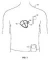
- Fig. 1illustrates an implantable apparatus 100 for blocking a left atrial appendage 102 of the heart 104.
- the apparatusincludes an implanted transponder unit 106, an interface communication unit 108, and portable control device 110.
- the transponder unit 106has a sensing mode in which the device senses one or more physiological conditions that are detectable within the LAA. Different embodiments will provide sensing of one or more physiological conditions. These physiological conditions include rhythm of the atria, pressure, transthoracic impedance, temperature, oxygen saturation, pH, etc.
- a sensing mode that senses pressure within the LAAindicates left ventricular filling pressures. Analyzing these pressure measurements, healthcare professionals may diagnose whether the patient is developing heart failure or there is contractile dysfunction of the heart.
- a sensing mode that senses transthoracic impedanceindicates the impedance across the chest wall. This impedance is reduced with fluid build up in the lungs and thus suggestive of heart failure.
- the sensed impedancemay be automatically or manually compared to previous impedance measurements, for example, to determine change over time.
- a sensing mode that sensing temperatureindicates core body temperature. From the measurement, healthcare professionals may diagnose any febrile illness.
- a sensing mode that records electrograms within the LAAcan enable immediate diagnosis of whether the patient is in sinus rhythm or AF.
- the transponder unit 106senses heart rhythms longitudinally so that arrhythmia burden can be defined over a period of time.
- the datamay be stored on an optional local memory 179 of the transponder unit 106, see Fig. 2A , or may be stored in a remote interface or controller as discussed further below.
- the transponder unit 106is a multimodal device capable of sensing in each mode. The sensing measurements may be made at periodic intervals, but are typically performed continuously. Furthermore, a control unit 110 with the transponder unit 106 is programmed to automatically alert the patient and/or physician if any of the measured physiological conditions reach a threshold level or otherwise indicate a warning condition for the patient. Such automatic detection and alert, based on the measured values from the transponder unit 106, is valuable because ⁇ 30% of patients with AF may be asymptomatic. Timely diagnosis of AF can be critically important to prevent thromboembolic complications such as stroke, unnecessary treatment with blood thinners which can lead to major potentially fatal bleeding complications and prevention of heart failure due to rapid rates during AF.
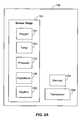
- the transponder unit 106includes a sensor stage 150 that is able to sense one or more physiological conditions within the LAA. That sensor stage may perform electrical monitoring of electrically-determined physiological conditions and/or monitoring for hemodynamically-determined physiology conditions (pressure, etc.).
- the sensor stagemay for example include a MEMS/NEMS fabricated oxygen content/saturation filter 151, a MEMS/NEMS fabricated pressure sensor 152, a MEMS/NEMS fabricated temperature sensor 154, and an MEMS/NEMS fabricated impedance measuring sensor 156, and a MEMS/NEMS fabricated rhythm sensor 158.
- the lattermay be include capability to record, filter, amplify, process and transmit electrograms.
- MEMSrefers to Micro Electromechanical Systems
- NEMSrefers to Nano Electromechanical Systems. For both known fabrication techniques suitable to form the devices described herein are contemplated.
- the transponder under 106communicates with the communication interface unit 108, which may be external to the patient, for example on a belt etc., or alternatively may be implanted internally within the patient, as shown in FIG. 1 .
- the interface unit 108includes a transceiver and wirelessly communicates with the transponder unit, in particular transceiver 184 (184') of the transponder unit 106.
- the transceiver 184communicates the sensed reporting signals, corresponding to the sensed measured values, to the interface unit 108. These include measurements of any of physiological conditions mentioned herein.
- the unit 108may communicate the received reporting signals from the transponder unit 106 to the control device 110, after signal amplification, noise reduction, any pre-filtering, and any preliminary data analysis. That communication may be wireless or through a wired means, such as through a universal serial bus (USB) connection to the control device 110.
- USBuniversal serial bus
- the control device 110may be a dedicated handheld, portable device displaying physiological conditions, such as pressure, temperature, and/or impedance.
- the device 110may display rhythm data for the heart as well.
- the device 110can display any of the sensed data from the transponder unit 106.
- the wireless communicationsmay be implemented using any standard protocol or specification, such as WiFi or any of the Institute of Electrical and Electronics Engineers (IEEE) 802.11 a, b, g, or n standards, BluetoothTM, Near Field Communication, radio-frequency identification (RFID) or others.
- IEEEInstitute of Electrical and Electronics Engineers
- the wireless communicationmay alternatively be implemented using a proprietary protocol.
- the device 110analyzes the received sensed signals and determines the physiological condition of the patient, such as the rhythm status, sinus rhythm (SR) and AF.
- the device 110also determines alarm conditions that can alert the patient and physician or other care provider, where such alarm conditions are displayed to the patient or care provider.
- a treatment instruction or instruction regimencan be prepared in response to the analysis of the device 110.
- the device 110is programmed to present actual instructions on a screen as to how to address the alarm condition.
- the control device 110may indeed be a stand-alone wireless device or incorporated into an existing system, such as a pacing/defibrillation system.
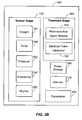
- the transponder unitis a multi-mode device, which in addition to the sensing mode capabilities described above, optionally includes a treatment mode, in which the device is able to treat conditions in the LAA or in the heart, more generally, such as atrial fibrillation or atrial flutter.
- the transponder unit 106'is shown having similar elements to those of Fig. 2A and also including a treatment stage 180 that, in the illustrated example, includes an electrical pulsing stage 182, which is used to apply an electrical pulse to the heart in response to a sensed atrial fibrillation condition or bradycardia (slow heart rate) condition such as may occur after conversion of AF to sinus rhythm sensed by the stage 150'.
- the transponder unit 106'further includes another treatment device in the form of a pharmaceutical agent release stage 183, which releases a pharmaceutical agent into the left atrial appendage for treatment of AF or heart failure or otherwise as determined from the sensor data from the sensor stage 150'.
- the pulse stage 182 and the pharmaceutical agent release stage 183are part of a control system in which, the sensor stage 150' determines one or more physiological conditions indicating, either alone or when combined with other condition data, an arrhythmia condition. In that control system, the sensor stage 150' then communicates the sensed signals to the communication interface 108, which then analyzes the signals to determine if an arrhythmia condition exists.
- control system of Fig. 2Bmay be an open loop system, in other examples, the control system is a closed loop system where the sensor stage 150' constantly senses the one or more physiological conditions and feeds the sensed signals into the interface 108 or control device 110 (of Fig. 1 ), which constantly update the treatment signals communicated to the treatment stage 180.
- control loop adjustmentmay occur at predetermined time intervals, for example, to achieve constant adjustment.
- the transponder 106/106'may be placed within the LAA using a conductive element.
- a biocompatible, inert filler material 200 injected into the LAA 102may be conductive, such that the sensor may sense a signal through or an electrical pulse generate may produce a signal through the material 200 to the inner walls 202 of the LAA 102.
- the transponder unit 106is supported by a strut support structure 300 which has conductive struts 302 extending from the transponder 106 to the walls of the LAA 102, such that sensing is from or treatment is applied to the walls of the LAA through struts 302.
- these conductive struts 302are also anchoring struts that engage the inner wall 202 of the LAA 102 and retain the transponder unit 106 without direct contact.
- FIG. 3Dillustrates a similar configuration to that of FIG. 3C , but with both struts 302 and the inert material 200 supporting the transponder unit 106 within the LAA 102.
- the transceiver 184receives treatment instructions signals from the unit 108 for controlling one or both of the electrical pulse generator 182 and the pharmaceutical agent release stage 183.
- the transponder unit 106includes an inductive power storage 186 which powers the unit 106 and which may be recharged by the interface unit 108 through an inductive recharging.
- the unit 108may be battery powered, for example.
- the chargingis achieved through radiofrequency induction, which may use a frequency of 125 MHz.
- the passive power mechanismmay be implemented by having the interface unit 108 interrogate the transponder unit 106 for new measurements using a poll signal.
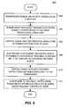
- FIG. 4is a process 400 used to deploy the transponder unit 106.
- insertion of a delivery catheteroccurs.
- a transeptal punctureis made using either one of the conventional catheter systems or using the delivery sheath, and dilator included in this description. If a conventional transeptal sheath is used, this is later exchanged with delivery sheath described herein using over the wire technique once the transeptal puncture and access to the left atrium is obtained.
- the delivery systemthat includes a delivery sheath through which a delivery catheter, such as catheter 190 in FIG. 3A , is positioned into the left atrium 192, the catheter 190 may be a 8-14 Fr sized catheter.
- the catheter 190Once the catheter 190 is positioned in place, with a distal end extending into the left atrium, the transponder unit 106, the material 200, and an occlusion device 194 (shown in FIG. 3A ) may be implanted.
- a biocompatible, inert materialis injected into the LAA to serve as a volume filler material, such as the material 200.
- the delivery catheter 190may be used with a dedicated delivery lumen formed inside the catheter 190.
- the material 200is in a liquid phase form and has not been converted to a solid phase.
- the materialis maintained in this liquid phase throughout injection into the LAA 102, thereby allowing the material 200 to better fill the entire LAA volume.
- the material 200is preferably biocompatible and inert, which means that it will not adversely affect conditions in the LAA or the blood flow system if introduced in the blood circulation.
- the inert biocompatible material 200may be, for example, silicone oil, a variety of polymers, polyethylene, polyester, and expanded polytetrafluoroethylene, PET, ePET, biomimetic hydrogels, polyvinyl alcohols (PVA), polycaprolactone, ovalbumin, biocompatible hydrogels, collagen, alginate hydrogel, polyethylene glycol, fibrin glue, poly(2-hydroxyethyl methacrylate) (PHEMA) and poly N-(2-hydroxypropyl)- methacrylamide (PHPMA), liquid embolic materials such as isobutyl-2 cyanoacrylate, and particulate embolic material such as spheres coated with iron or barium, or silicone particles, N-butyl cyanoacrylate (NBCA) (that hardens a soon as it gets in contact with blood or ionic
- biocompatible, inert materialsmay also be used. However, it may be desirable to prevent that material from exiting the LAA during this initial injection stage. Therefore, the amount of material 200 introduced into the LAA 102 may be monitored against leakage of the biocompatible material.
- This materialcan also be radio-opaque or echogenic so that delivery of the material can be monitored by X-ray or ultrasound (intracardiac, transesophageal or surface echocardiography).
- an RCAradio contrast agents
- an x-ray imaging systemwill be able to display RCA and thereby identify if any of the material is escaping the LAA.
- Other visualizable mediamay be introduced instead.
- the delivery cathetermay contain a deliver lumen or capillary used to introduce the agent from the catheter to the material trapped in the LAA.
- an intracardiac ultrasoundmay be used to visualize the material, relying upon the difference in density of the injected material versus that of the heart tissue.
- An exampleis a transesophageal ultrasound device, which when inserted into the esophagus can be used for highly identifiable imaging of the left atrium. In any event, these techniques may be particularly useful as they are also often used for catheter positioning anyway.
- biocompatible, inert compositionsmay be used for the material 200. These include classes of materials, such as various polymers.
- the materialsare biocompatible, inert, lightweight and low density.
- the materialsPreferably have a liquid phase that may be controllably converted into a solid phase by a stimulus.
- the process 400determines whether the appropriate amount of the material 200 has been delivered, e.g., whether the material has completely or sufficiently filled the LAA.
- the processenters a second stage (indicated by block 408) to convert the material from a liquid phase to a solid phase.
- the material within the LAA 102is actively converted from a liquid phase to a solid phase, where active conversion refers to using a controllable mechanism to initiate conversion from the liquid phase to the solid phase.
- An example active mechanismis the introduction of a catalyst material into the LAA that induces a solid phase in the material 200, e.g., where that catalyst is formed of another biocompatible, inert material.
- Another example technique for actively converting the material 200 within the LAA 102 from a fluid to a solid phaseis by applying an electrical current, heat or light to induce the phase change in the material 200.
- the medical professionalcan more accurately control when the injected material will be solidified, which helps reduce the risk of embolism during the procedure and which also allows the medical professional to better control the amount of material inserted into the LAA.
- the latteris important for maximizing the amount of LAA volume closed off.
- Non-active techniques for liquid-to-solid phase conversationare also contemplated. These include transitions that occur naturally over time, e.g., in response to body temperature, or in response to blood entering the LAA.
- FIGS. 3A-3Dillustrate various examples apparatuses for implanting transponders, each shown in a deployed stage.
- the transponder unit 106is inserted into the LAA 102 by the delivery catheter 190 and during the material injection process of FIG. 4 , for example, between the first stage of injection and the second stage of active phase change.
- the transponder unit 106may be inserted through another lumen channel in the catheter 190, while in other examples, the transponder unit 106 is maintained at a distal end of the catheter 190, for example, along with the occlusion device 194, which as shown in FIGS. 6a-6g can have an umbrella, butterfly, balloon or other design.
- FIG. 3Bprovides a more focused view of the configuration of FIG. 3A , showing the material 200 filling the entire volume and with the occlusion device 194 in place occluding the ostium 120 of the LAA 102.
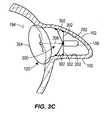
- Fig. 3Cillustrates another example apparatus in which the transponder unit 106 is injected into the LAA 102 as part of the occlusion device 194.
- That occlusion device 194includes a membrane structure 304 that covers the entire ostium 120 of the LAA 102 when deployed and is retained in place against the ostium 120 and the LAA 102 through the strut support structure 300.
- the struts 302form anchor struts that are initially collapsed at least partially or fully along a longitudinal mainstay strut 306 until sufficiently deployed in the LAA 102. The struts 302 may then be deployed from which they will extend radially outward from the mainstay strut 306 to engage the inner wall 202 of the LAA 102.
- the struts 302are in a staggered length and engage the inner wall 202 transversely, from the mainstay strut 306, and engage the inner wall 202 in an articulated fashion, in which longer struts engage portions of the inner wall 202 such that at least a portion of any lateral pulling force on the strut support structure 300 (i.e., pulling on the mainstay strut 306) will be counteracted by a lateral retaining force from these struts.
- Fig. 3Dillustrates an example similar to that of FIG. 3C , but showing the filler material 200 in place.
- the struts 302may be maintained against the inner wall 202 through means such as a spring force, pinch attachment, hooking end, etc.
- the filtering membrane 304may be made of biocompatible materials, such as, for example, ePFTE (e.g., Gortex.RTM.), polyester (e.g., Dacron.RTM.), PTFE (e.g., Teflon.RTM.), silicone, urethane, metal fibers, or other biocompatible polymers.
- ePFTEe.g., Gortex.RTM.
- polyestere.g., Dacron.RTM.
- PTFEe.g., Teflon.RTM.
- siliconee.g., silicone, urethane, metal fibers, or other biocompatible polymers.
- the membrane 304may be impermeable to blood ingress.
- the membrane 304may be porous allowing blood to flow therethrough while blocking or inhibiting the passage of thrombus, clots, or emboli formed within the atrial appendage from entering the atrium of the heart and, the patient's bloodstream.
- Using a permeable membranemay reduce the risk of leakage about the periphery of the filtering membrane, or of dislodgement of the occlusion device that may result from the exertion of pressure against the surface of the occlusion device. Allowing the blood flow through and across the membrane 304 may relieve this pressure, sufficiently and in a controlled manner, to reduce such leakage or dislodgement.
- Tissue in-growthmay additionally secure the occlusion device 194 to the opening of the LAA 102. More particularly, the growth of tissue may occur along the outer periphery of the occlusion device. This tissue growth, in cooperation with the pressure relief provided by the permeable structure, may provide additional means of reducing leakage about the periphery of the occlusion device. Tissue growth may eventually cover additional surface area of the membrane of the occlusion device.
- Fig. 5illustrates a process 500 for diagnosing atrial fibrillation or atrial flutter.
- a transponder unitsenses one or more physiological conditions and then wirelessly transmits (e.g., block 504) reporting signals corresponding to those sensed physiological conditions to the control device, either directly (as discussed in relation to Fig. 5 ) or through a communication interface unit.
- the control deviceanalyzes the received reporting signals and determines rhythm state of heart, e.g., whether the heart is experiencing SR, or AF. In response to the determination, the control device alerts the patient and/or the physician, via a block 508.
- the processmay further automatically develop treatment instructions and send those instructions wirelessly to the transponder, via a block 510.
- treatment instructionsmay include instructions to the stage 182 for application of electrical pulse signals to heart through LAA and/or instructions to the stage 183 to deliver of a treatment agent into the LAA, which instructions may then be performed using the transponder device and the treatment stage 180, via block 512.
- the stage 183is connected to an external, deployed therapeutic agent reservoir within the LAA or to reservoir within the transponder unit 106.
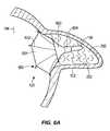
- FIGS. 6a-6gillustrate various example occlusion devices that are configured to allow for injection of a filler material into the LAA and implantation of a transponder unit into the LAA for sensing and wireless communications.
- the inert filler material 200may have any of the characteristics, features, or functions described in the examples above.
- Fig. 6Aillustrates another example apparatus in which the occlusion device 194 has an inverted umbrella design and the transponder unit 106 is part of the occlusion device 194.
- the occlusion device 194includes a membrane structure 601 that covers the entire ostium 120 of the LAA 102 when deployed and is retained in place against the ostium 120 and the LAA 102 through the strut support structure 600.
- the support ring 604, strut base 603, and filler material 200maintains the struts 602 in the proper configuration.
- the struts 602may be configured for attachment to the walls of the ostium 120 on the outer sides thereof through similar means as with struts 302 in Fig. 3C above.
- the struts 602are initially collapsed at least partially or fully collapsed along the longitudinal axis of the catheter 190 until the delivery sheath causes the struts 602 to extend radially outward and engage the outer wall of the ostium 120.
- Fig. 6Dillustrates another example apparatus in which the occlusion device 194 has an umbrella design.
- the membrane structure 605is drawn up against the ostium 120 by ratcheting the membrane structure along pole 610, shown in Fig. 6B .
- the pawl mechanism 606engages teeth 607 on pole 610 and is moved forward to snugly position the membrane structure 605 across the ostium 120.
- the filler material 200provides additional support, in conjunction with the strut support structure comprised of struts 608, to help maintain the membrane structure 605 in place.
- Figs. 6B-6Cillustrate a method of delivery and deployment for the example apparatus of Fig. 6D .
- the umbrella opening structure 609can be pushed to the open position (by a surgeon) or have a spring loaded mechanism to push the struts 608 to the open position.
- the ends of the umbrella struts 608engage the LAA wall around the ostium 120 and prevent the umbrella design strut support structure from being withdrawn from the LAA.
- Fig. 6Eillustrates another example apparatus in which the occlusion device 194 has a balloon design.
- the transponder unit 106is embedded within the balloon occlusion device 194 in inflation material 611.
- the balloon 612may be made from a compliant or non-compliant polymer, examples of which include silicone, polyethylene, polyurethane, and PET.
- the outside surface of the balloonmay contain a material to induce fibrosis.
- Inflation material 611can be gas, fluid or gel that is injected under pressure through the delivery catheter 190.
- the inflation materialcould also be a polymer that can be hardened.
- the inflation materialcan also contain a radiopaque dye or other visualizable media.
- Fig. 6Fillustrates another example apparatus in which the occlusion device 194 that utilizes an anchor balloon design.
- the balloon 613expands within the LAA and secures the membrane structure 614 in place.
- the balloon 613is expanded prior to complete placement within the LAA, and the expanded balloon is then inserted into the distal end of the LAA cavity.
- the transponder 106is attached to connecting rod 615 which is itself fixedly attached to and in between both the balloon 613 and the membrane structure 614.
- the transponder unit 106may be conductively paired with the interior LAA wall 202 through conductive balloon 612.
- the balloon 612does not provide a conductive channel and instead serves only to provide support and stability for the occlusion device 194 and transponder unit 106.
- the balloon and filler materialmay be the same as described above with regards to the example illustrated in Fig. 6E .
- Fig. 6Gillustrates another example apparatus in which the occlusion device 194 is of a butterfly design.
- Membrane structure 616is secured in place by the anchor balloon 617 and positioned across the ostium 120.
- the outer edge of the membrane structure 616may be directly engaged with the atrial wall surrounding the ostium 120.
- the anchor balloon 617is initially collapsed and later expanded once inserted into the LAA.
- the transponder unit 106is attached to the anchor balloon 617 and embedded in filler material 200 within the LAA.
- Certain examplesmay be better suited for certain individual characteristics, such as the size and shape of the ostium 120 and LAA 102.
- the umbrella design illustrated in Figs. 6A-6D and the balloon design illustrated in Fig. 6Emay be better suited where the interior wall of ostium 120 is small such that it does not form a ledge on the interior of the LAA 102.
- the umbrella and balloon design examples of Figs. 6A-6D and 6Eare further advantageous as being adaptable to fit a wide range of LAA sizes and shapes, providing near-universal fit.
- the anchor balloon design of Fig. 6Fmay be design more suited for where the distal end of the LAA 102 is larger.
- the anchor ballooncan serve to expand the distal end of the LAA 102 to more securely engage the anchor inside the LAA.
- the butterfly design illustrated in Fig. 6Gmay be more effective where the size of the ostium 120 and the shape of the LAA 102 coincide such that the interior ostium wall 120 forms a ledge against which an anchor-structure may engage along the interior of the LAA 102.
- Certain examplesmay additionally be advantageous as providing more rigid placement across the ostium 120, or alternatively, more flexible placement adaptable to movement of the ostium 120 and LAA 102.
- Certain examplesmay additionally provide a simpler deployment procedure than others.
- the inverse-umbrella structure of Fig. 6Arequires just a two step deployment process, involving the opening of the umbrella-shaped membrane structure 605 and the securing of the membrane structure across the ostium. This may be advantageous over other more complicated processes, such as the three step deployment example illustrated in Figs. 6B-6D .
- the filler materialis injected into the LAA prior to deployment of the occlusion device 194 and transponder unit 106.
- the filler materialis injected after the occlusion device and transponder unit have been deployed and secured into place. In the latter, the filler material might be injected through a delivery catheter operatively coupled to an injection mechanism on the occlusion device 194.
- the LAA 102might first be evacuated of thrombi through the use of an aspiration catheter or other aspirational means prior to injection of the filler material 200.
- the filler material 200might be injected without prior aspiration. In both cases, the filler material serves to obliterate the left atrial appendage space.
- the present techniquesare described for use in the LAA, they may be also be implemented on the right atrial appendage or more generally in any vessel or aperture in the body in which blood is permitted to flow therethrough, in which blood clots may be formed and thus it desired to prevent such formations from embolizing and entering into the blood stream.
- the present applicationis not limited to this or any particular AF patient.
- the present techniquesmay be applied to arterial or venous aneurysms, etc.
- Various blocks, operations, and techniques described abovemay be implemented in hardware, firmware, software, or any combination of hardware, firmware, and/or software.
- some or all of the blocks, operations, techniques, etc.may be implemented in, for example, a custom integrated circuit (IC), an application specific integrated circuit (ASIC), a field programmable logic array (FPGA), a programmable logic array (PLA), etc.
- ICintegrated circuit
- ASICapplication specific integrated circuit
- FPGAfield programmable logic array
- PDAprogrammable logic array
- the softwareWhen implemented in software, the software may be stored in any computer readable memory such as on a magnetic disk, or other storage medium, in a RAM or ROM or flash memory of a computer, processor, hard disk drive, optical disk drive, tape drive, etc.
- the present inventionthus may include software for controlling hardware (e.g., a computer) capable of executing instructions stored on the computer readable medium and for enabling that hardware to interact with a human user.
- softwaremay include, but is not limited to, device drivers, operating systems and user applications, such as development tools.
- Such computer readable mediafurther includes the computer program product of the present invention for performing the inventive method of the present invention.
- the computer code devices of the present inventioncan be any interpreted or executable code mechanism, including but not limited to scripts, interpreters, dynamic link libraries, Java classes, and complete executable programs.
- parts of the processing of the present inventionmay be distributed for better performance, reliability, and/or cost. For example, an outline or image may be selected on a first computer and sent to a second computer for remote diagnosis.
- the inventionmay also be implemented by the preparation of application specific integrated circuits or by interconnecting an appropriate network of conventional component circuits, as will be readily apparent to those skilled in the art.
Landscapes
- Health & Medical Sciences (AREA)
- Life Sciences & Earth Sciences (AREA)
- Surgery (AREA)
- Engineering & Computer Science (AREA)
- Veterinary Medicine (AREA)
- Public Health (AREA)
- General Health & Medical Sciences (AREA)
- Biomedical Technology (AREA)
- Animal Behavior & Ethology (AREA)
- Molecular Biology (AREA)
- Medical Informatics (AREA)
- Heart & Thoracic Surgery (AREA)
- Nuclear Medicine, Radiotherapy & Molecular Imaging (AREA)
- Vascular Medicine (AREA)
- Reproductive Health (AREA)
- Cardiology (AREA)
- Computer Networks & Wireless Communication (AREA)
- Physics & Mathematics (AREA)
- Biophysics (AREA)
- Pathology (AREA)
- Radiology & Medical Imaging (AREA)
- Surgical Instruments (AREA)
Description
- The present invention relates generally to devices for analysis and treatment of the heart and more particularly to a multimodality device for left atrial appendage occlusion.
- Atrial fibrillation (AF) is the leading cause of strokes due to thrombi (e.g., blood clots) that predominantly form in the left atrial appendage (LAA) and then subsequently embolize.
- There are, of course, a number of treatments to prevent, or more accurately reduce the risk of, stroke. But the treatments are lacking. For example, although systemic anticoagulation using warfarin has been used to minimize the risk of stroke, warfarin is nonetheless associated with a 0.5-1% per year risk of major bleeding including intracranial bleeding. Furthermore, not all patients are eligible to take warfarin due to risk of bleeding. More importantly, patients at highest risk for strokes often are also at highest risk of bleeding and cannot take warfarin.
- Document
US 6,551,303 B1 discloses a membrane or plug structure applied to the ostium of an atrial appendage for preventing blood flow and physical connection between an atrium of the heart and the associated atrial appendages to isolate an atrial appendage and prevent thrombus leaving therefrom. - There is need for a device that will effectively prevent thrombi formation and embolism, and preferably provide additional functionality to treat a patient experiencing AF.
- The present application describes an apparatus that hinders or even prevents thrombus buildup in the first instance. The apparatus not only occludes the LAA, the apparatus eliminates the potential space within the LAA where thrombus formation could form. Numerous examples are described, but principally, an occlusion device is used to block the orifice opening of the LAA, i.e., the ostium, where the occlusion device is configured to allow injection of a biocompatible, inert material into the LAA during implantation. This material is used to fill the LAA acting as a bulking agent. The material may be injected directly into the LAA or in an expandable balloon within the LAA and is maintained in a liquid phase during implantation, which allows the material to better fill the entire LAA volume. In some examples, the occlusion device caps the fluid preventing it from spilling out of the LAA, and thus avoiding the possibility of embolism. In other examples, the fluid levels are monitored during insertion to prevent spillover. Either way, preferably the material is maintained in the liquid phase throughout insertion and then actively converted it into a solid phase by a controllable mechanism, such as application of a catalyst material into the LAA that induces a solid phase in the material or application of an electrical current, radiofrequency energy, heat, light, etc that solidifies the material. In other examples, the transition from liquid phase to solid phase occurs naturally over time, in response to body temperature, or in response to blood entering the LAA. In some examples, the biocompatible, inert material is conductive.
- The device includes a delivery catheter through which the apparatus is deployed, including the occlusion device and the inert material. The occlusion device may take the form of an umbrella, butterfly or a balloon design to include the orifice of the LAA during deployment.
- In some examples, the apparatus also includes a MEMS transponder unit, which is deployed into the LAA before, during, or after injection of the biocompatible material, and then retained in the material after hardening to the solid phase. The transponder serves to record and transmit electrical activity of the LAA, either through conductive media or by direct contact to the LAA wall. The transponder may record electrical activity and electrograms, pressure, transthoracic impedance, temperature, pH, oxygen saturation. The recorded values are then transmitted wirelessly to an interface communications device, which may be located internally, within the body, or external to the body, and which performs preprocessing on the signals from the transponder, such as, bandwidth filtering, noise reduction, and signal amplification. In some examples, the interface device performs preliminary analysis of the received signal, e.g., converting raw signal data into numerically representative form.
- The transponder is preferably self-powered, through a rechargeable power unit that may be recharged inductively using the interface device or other device.
- An embodiment of the present invention is an implantable apparatus for blocking a left atrial appendage, the apparatus comprising: an occlusion device having a positioning stage in which the occlusion device is collapsed for positioning the occlusion device at an opening of the left atrial appendage, the occlusion device having a cover that in a deployed stage encloses the opening and a strut support structure that in a deployed stage fixedly engage the cover to enclose the opening; and a transponder unit configured to sense a physiological condition, the transponder unit having a wireless transmitter for transmitting reporting signals indicating the sensed physiological condition, the transponder unit is connected to the strut support structure such that in the deployed stage the strut support structure maintains engagement with the transponder unit and positions the transponder unit within the left atrial appendage for sensing the physiological condition within the left atrial appendage.
- In another embodiment, an implantable apparatus for blocking a left atrial appendage comprises: an occlusion device having a positioning stage in which the occlusion device is collapsed for positioning the occlusion device at an opening of the left atrial appendage, the occlusion device having a cover that in a deployed stage encloses the opening and a strut support structure that in a deployed stage fixedly engages the cover to enclose the opening; a transponder unit configured to sense a plurality of physiological conditions and configured to wirelessly transmit sensed measurements of the physiological conditions to an external receiver; and a biocompatible, inert material in liquid phase inserted into the left atrial appendage, wherein the biocompatible, inert material freely suspends the transponder unit within the left atrial appendage.
- The features, functions, and advantages can be achieved independently in various embodiments of the present invention or may be combined in yet other embodiments.
FIG. 1 illustrates an implantable apparatus for blocking the left atrial appendage, showing an implanted transponder, interface communication unit, and portable control device, in accordance with an example;FIG. 2A is block diagram of an example transponder unit as may be used in the implantable apparatus ofFIG. 1 ;FIG. 2B is block diagram of another example transponder unit as may be used in the implantable apparatus ofFIG. 1 ;FIG. 3A illustrates the deployment stage of an implantable apparatus for blocking the left atrial appendage, with the apparatus implanted in direct contact with an inner wall of the LAA;FIG. 3B illustrates the deployment stage of an implantable apparatus for blocking the left atrial appendage, with the apparatus implanted suspended within the LAA out of direct contact with an inner wall;FIG. 3C illustrates the deployment stage of an implantable apparatus for blocking the left atrial appendage, with the apparatus implanted suspended in the LAA by a strut support structure of an occlusion device;FIG. 3D illustrates another example of the deployment stage of an implantable apparatus for blocking the left atrial appendage;FIG. 4 illustrates a process for deploying an implantable apparatus for blocking the left atrial appendage;FIG. 5 illustrates a process for treating atrial fibrillation or atrial flutter ;FIGS. 6A - 6G illustrate various example occlusion devices that may be used in the apparatus of claim 1 to close off the ostium of the LAA;Fig. 1 illustrates animplantable apparatus 100 for blocking a leftatrial appendage 102 of theheart 104. The apparatus includes an implantedtransponder unit 106, aninterface communication unit 108, andportable control device 110.- The
transponder unit 106 has a sensing mode in which the device senses one or more physiological conditions that are detectable within the LAA. Different embodiments will provide sensing of one or more physiological conditions. These physiological conditions include rhythm of the atria, pressure, transthoracic impedance, temperature, oxygen saturation, pH, etc. - A sensing mode that senses pressure within the LAA indicates left ventricular filling pressures. Analyzing these pressure measurements, healthcare professionals may diagnose whether the patient is developing heart failure or there is contractile dysfunction of the heart.
- A sensing mode that senses transthoracic impedance indicates the impedance across the chest wall. This impedance is reduced with fluid build up in the lungs and thus suggestive of heart failure. The sensed impedance may be automatically or manually compared to previous impedance measurements, for example, to determine change over time.
- A sensing mode that sensing temperature indicates core body temperature. From the measurement, healthcare professionals may diagnose any febrile illness.
- A sensing mode that records electrograms within the LAA can enable immediate diagnosis of whether the patient is in sinus rhythm or AF. In some examples, the
transponder unit 106 senses heart rhythms longitudinally so that arrhythmia burden can be defined over a period of time. The data may be stored on an optionallocal memory 179 of thetransponder unit 106, seeFig. 2A , or may be stored in a remote interface or controller as discussed further below. - In the illustrated example, the
transponder unit 106 is a multimodal device capable of sensing in each mode. The sensing measurements may be made at periodic intervals, but are typically performed continuously. Furthermore, acontrol unit 110 with thetransponder unit 106 is programmed to automatically alert the patient and/or physician if any of the measured physiological conditions reach a threshold level or otherwise indicate a warning condition for the patient. Such automatic detection and alert, based on the measured values from thetransponder unit 106, is valuable because~30% of patients with AF may be asymptomatic. Timely diagnosis of AF can be critically important to prevent thromboembolic complications such as stroke, unnecessary treatment with blood thinners which can lead to major potentially fatal bleeding complications and prevention of heart failure due to rapid rates during AF. - As shown in
FIG. 2A , thetransponder unit 106 includes asensor stage 150 that is able to sense one or more physiological conditions within the LAA. That sensor stage may perform electrical monitoring of electrically-determined physiological conditions and/or monitoring for hemodynamically-determined physiology conditions (pressure, etc.). The sensor stage may for example include a MEMS/NEMS fabricated oxygen content/saturation filter 151, a MEMS/NEMS fabricatedpressure sensor 152, a MEMS/NEMS fabricatedtemperature sensor 154, and an MEMS/NEMS fabricatedimpedance measuring sensor 156, and a MEMS/NEMS fabricatedrhythm sensor 158. The latter may be include capability to record, filter, amplify, process and transmit electrograms. As used herein MEMS refers to Micro Electromechanical Systems; and NEMS refers to Nano Electromechanical Systems. For both known fabrication techniques suitable to form the devices described herein are contemplated. - The transponder under 106 communicates with the
communication interface unit 108, which may be external to the patient, for example on a belt etc., or alternatively may be implanted internally within the patient, as shown inFIG. 1 . Either way theinterface unit 108 includes a transceiver and wirelessly communicates with the transponder unit, in particular transceiver 184 (184') of thetransponder unit 106. Thetransceiver 184 communicates the sensed reporting signals, corresponding to the sensed measured values, to theinterface unit 108. These include measurements of any of physiological conditions mentioned herein. - The
unit 108 may communicate the received reporting signals from thetransponder unit 106 to thecontrol device 110, after signal amplification, noise reduction, any pre-filtering, and any preliminary data analysis. That communication may be wireless or through a wired means, such as through a universal serial bus (USB) connection to thecontrol device 110. - The
control device 110 may be a dedicated handheld, portable device displaying physiological conditions, such as pressure, temperature, and/or impedance. Thedevice 110 may display rhythm data for the heart as well. Thedevice 110 can display any of the sensed data from thetransponder unit 106. - The wireless communications may be implemented using any standard protocol or specification, such as WiFi or any of the Institute of Electrical and Electronics Engineers (IEEE) 802.11 a, b, g, or n standards, Bluetooth™, Near Field Communication, radio-frequency identification (RFID) or others. The wireless communication may alternatively be implemented using a proprietary protocol.
- In some examples, the
device 110 analyzes the received sensed signals and determines the physiological condition of the patient, such as the rhythm status, sinus rhythm (SR) and AF. Thedevice 110 also determines alarm conditions that can alert the patient and physician or other care provider, where such alarm conditions are displayed to the patient or care provider. A treatment instruction or instruction regimen can be prepared in response to the analysis of thedevice 110. In some examples, thedevice 110 is programmed to present actual instructions on a screen as to how to address the alarm condition. - The
control device 110 may indeed be a stand-alone wireless device or incorporated into an existing system, such as a pacing/defibrillation system. - In some examples, the transponder unit is a multi-mode device, which in addition to the sensing mode capabilities described above, optionally includes a treatment mode, in which the device is able to treat conditions in the LAA or in the heart, more generally, such as atrial fibrillation or atrial flutter. In
Fig. 2B , the transponder unit 106' is shown having similar elements to those ofFig. 2A and also including atreatment stage 180 that, in the illustrated example, includes anelectrical pulsing stage 182, which is used to apply an electrical pulse to the heart in response to a sensed atrial fibrillation condition or bradycardia (slow heart rate) condition such as may occur after conversion of AF to sinus rhythm sensed by the stage 150'. The transponder unit 106' further includes another treatment device in the form of a pharmaceuticalagent release stage 183, which releases a pharmaceutical agent into the left atrial appendage for treatment of AF or heart failure or otherwise as determined from the sensor data from the sensor stage 150'. - In some examples, the
pulse stage 182 and the pharmaceuticalagent release stage 183 are part of a control system in which, the sensor stage 150' determines one or more physiological conditions indicating, either alone or when combined with other condition data, an arrhythmia condition. In that control system, the sensor stage 150' then communicates the sensed signals to thecommunication interface 108, which then analyzes the signals to determine if an arrhythmia condition exists. - While the control system of
Fig. 2B may be an open loop system, in other examples, the control system is a closed loop system where the sensor stage 150' constantly senses the one or more physiological conditions and feeds the sensed signals into theinterface 108 or control device 110 (ofFig. 1 ), which constantly update the treatment signals communicated to thetreatment stage 180. Such control loop adjustment may occur at predetermined time intervals, for example, to achieve constant adjustment. - To facilitate both sensing and treatment, the
transponder 106/106' may be placed within the LAA using a conductive element. First, as shown in the example ofFig. 3B (discussed further below), when the transponder unit 106 - unit 106' though not shown would be used in the illustrated example the same way - is suspended within theLAA 102, then a biocompatible,inert filler material 200 injected into theLAA 102 may be conductive, such that the sensor may sense a signal through or an electrical pulse generate may produce a signal through the material 200 to theinner walls 202 of theLAA 102. Fig. 3C , thetransponder unit 106 is supported by astrut support structure 300 which hasconductive struts 302 extending from thetransponder 106 to the walls of theLAA 102, such that sensing is from or treatment is applied to the walls of the LAA throughstruts 302. In the illustrated example theseconductive struts 302 are also anchoring struts that engage theinner wall 202 of theLAA 102 and retain thetransponder unit 106 without direct contact.FIG. 3D illustrates a similar configuration to that ofFIG. 3C , but with bothstruts 302 and theinert material 200 supporting thetransponder unit 106 within theLAA 102.- In some examples, the
transceiver 184 receives treatment instructions signals from theunit 108 for controlling one or both of theelectrical pulse generator 182 and the pharmaceuticalagent release stage 183. - The
transponder unit 106 includes aninductive power storage 186 which powers theunit 106 and which may be recharged by theinterface unit 108 through an inductive recharging. In such a configuration, theunit 108 may be battery powered, for example. - In some examples, the charging is achieved through radiofrequency induction, which may use a frequency of 125 MHz. For example, the passive power mechanism may be implemented by having the
interface unit 108 interrogate thetransponder unit 106 for new measurements using a poll signal. FIG. 4 is aprocess 400 used to deploy thetransponder unit 106. At aninitial block 402, insertion of a delivery catheter occurs. First a transeptal puncture is made using either one of the conventional catheter systems or using the delivery sheath, and dilator included in this description. If a conventional transeptal sheath is used, this is later exchanged with delivery sheath described herein using over the wire technique once the transeptal puncture and access to the left atrium is obtained. Then the delivery system that includes a delivery sheath through which a delivery catheter, such ascatheter 190 inFIG. 3A , is positioned into theleft atrium 192, thecatheter 190 may be a 8-14 Fr sized catheter. Once thecatheter 190 is positioned in place, with a distal end extending into the left atrium, thetransponder unit 106, thematerial 200, and an occlusion device 194 (shown inFIG. 3A ) may be implanted.- As shown in
Fig. 4 , with the delivery catheter in position, at ablock 404, a biocompatible, inert material is injected into the LAA to serve as a volume filler material, such as thematerial 200. To deliver thematerial 200, thedelivery catheter 190 may be used with a dedicated delivery lumen formed inside thecatheter 190. - In this initial stage of the process, the
material 200 is in a liquid phase form and has not been converted to a solid phase. Preferably the material is maintained in this liquid phase throughout injection into theLAA 102, thereby allowing thematerial 200 to better fill the entire LAA volume. - The
material 200 is preferably biocompatible and inert, which means that it will not adversely affect conditions in the LAA or the blood flow system if introduced in the blood circulation. The inertbiocompatible material 200 may be, for example, silicone oil, a variety of polymers, polyethylene, polyester, and expanded polytetrafluoroethylene, PET, ePET, biomimetic hydrogels, polyvinyl alcohols (PVA), polycaprolactone, ovalbumin, biocompatible hydrogels, collagen, alginate hydrogel, polyethylene glycol, fibrin glue, poly(2-hydroxyethyl methacrylate) (PHEMA) and poly N-(2-hydroxypropyl)- methacrylamide (PHPMA), liquid embolic materials such as isobutyl-2 cyanoacrylate, and particulate embolic material such as spheres coated with iron or barium, or silicone particles, N-butyl cyanoacrylate (NBCA) (that hardens a soon as it gets in contact with blood or ionic material such as saline) polyvinyl alcohol sponge (PVA), gelfoam, ethanol or other alcohols, or microcoils. Other biocompatible, inert materials may also be used. However, it may be desirable to prevent that material from exiting the LAA during this initial injection stage. Therefore, the amount ofmaterial 200 introduced into theLAA 102 may be monitored against leakage of the biocompatible material. This material can also be radio-opaque or echogenic so that delivery of the material can be monitored by X-ray or ultrasound (intracardiac, transesophageal or surface echocardiography). - To monitor the amount of
material 200 delivered to theLAA 102, more specifically to monitor the fluid levels and prevent leakage, at ablock 406, an RCA (radio contrast agents), i.e., radiopaque dye, may be used in the material to visually indicate if there is leakage. An x-ray imaging system will be able to display RCA and thereby identify if any of the material is escaping the LAA. Other visualizable media may be introduced instead. In either example, the delivery catheter may contain a deliver lumen or capillary used to introduce the agent from the catheter to the material trapped in the LAA. In another example, an intracardiac ultrasound (or some other ultrasound) may be used to visualize the material, relying upon the difference in density of the injected material versus that of the heart tissue. An example is a transesophageal ultrasound device, which when inserted into the esophagus can be used for highly identifiable imaging of the left atrium. In any event, these techniques may be particularly useful as they are also often used for catheter positioning anyway. - Various biocompatible, inert compositions may be used for the
material 200. These include classes of materials, such as various polymers. - While example classes of materials are described, it will be apparent that any suitable materials may be used, where the materials are biocompatible, inert, lightweight and low density. Preferably the materials have a liquid phase that may be controllably converted into a solid phase by a stimulus.
- Generally speaking, after the
material 200 has been delivered, theprocess 400 determines whether the appropriate amount of thematerial 200 has been delivered, e.g., whether the material has completely or sufficiently filled the LAA. - If the appropriate amount of the
material 200 has been delivered, the process enters a second stage (indicated by block 408) to convert the material from a liquid phase to a solid phase. Specifically, the material within theLAA 102 is actively converted from a liquid phase to a solid phase, where active conversion refers to using a controllable mechanism to initiate conversion from the liquid phase to the solid phase. An example active mechanism is the introduction of a catalyst material into the LAA that induces a solid phase in thematerial 200, e.g., where that catalyst is formed of another biocompatible, inert material. - Another example technique for actively converting the
material 200 within theLAA 102 from a fluid to a solid phase is by applying an electrical current, heat or light to induce the phase change in thematerial 200. - By using an active mechanism, the medical professional can more accurately control when the injected material will be solidified, which helps reduce the risk of embolism during the procedure and which also allows the medical professional to better control the amount of material inserted into the LAA. The latter is important for maximizing the amount of LAA volume closed off.
- Non-active techniques for liquid-to-solid phase conversation are also contemplated. These include transitions that occur naturally over time, e.g., in response to body temperature, or in response to blood entering the LAA.
FIGS. 3A-3D illustrate various examples apparatuses for implanting transponders, each shown in a deployed stage. InFIG. 3A , thetransponder unit 106 is inserted into theLAA 102 by thedelivery catheter 190 and during the material injection process ofFIG. 4 , for example, between the first stage of injection and the second stage of active phase change. Thetransponder unit 106 may be inserted through another lumen channel in thecatheter 190, while in other examples, thetransponder unit 106 is maintained at a distal end of thecatheter 190, for example, along with theocclusion device 194, which as shown inFIGS. 6a-6g can have an umbrella, butterfly, balloon or other design.FIG. 3B provides a more focused view of the configuration ofFIG. 3A , showing thematerial 200 filling the entire volume and with theocclusion device 194 in place occluding theostium 120 of theLAA 102.Fig. 3C illustrates another example apparatus in which thetransponder unit 106 is injected into theLAA 102 as part of theocclusion device 194. Thatocclusion device 194 includes amembrane structure 304 that covers theentire ostium 120 of theLAA 102 when deployed and is retained in place against theostium 120 and theLAA 102 through thestrut support structure 300. Thestruts 302 form anchor struts that are initially collapsed at least partially or fully along alongitudinal mainstay strut 306 until sufficiently deployed in theLAA 102. Thestruts 302 may then be deployed from which they will extend radially outward from themainstay strut 306 to engage theinner wall 202 of theLAA 102. Preferably thestruts 302 are in a staggered length and engage theinner wall 202 transversely, from themainstay strut 306, and engage theinner wall 202 in an articulated fashion, in which longer struts engage portions of theinner wall 202 such that at least a portion of any lateral pulling force on the strut support structure 300 (i.e., pulling on the mainstay strut 306) will be counteracted by a lateral retaining force from these struts.Fig. 3D illustrates an example similar to that ofFIG. 3C , but showing thefiller material 200 in place.- The
struts 302 may be maintained against theinner wall 202 through means such as a spring force, pinch attachment, hooking end, etc. - The
filtering membrane 304 may be made of biocompatible materials, such as, for example, ePFTE (e.g., Gortex.RTM.), polyester (e.g., Dacron.RTM.), PTFE (e.g., Teflon.RTM.), silicone, urethane, metal fibers, or other biocompatible polymers. - The
membrane 304 may be impermeable to blood ingress. In other examples, themembrane 304 may be porous allowing blood to flow therethrough while blocking or inhibiting the passage of thrombus, clots, or emboli formed within the atrial appendage from entering the atrium of the heart and, the patient's bloodstream. Using a permeable membrane may reduce the risk of leakage about the periphery of the filtering membrane, or of dislodgement of the occlusion device that may result from the exertion of pressure against the surface of the occlusion device. Allowing the blood flow through and across themembrane 304 may relieve this pressure, sufficiently and in a controlled manner, to reduce such leakage or dislodgement. Tissue in-growth may additionally secure theocclusion device 194 to the opening of theLAA 102. More particularly, the growth of tissue may occur along the outer periphery of the occlusion device. This tissue growth, in cooperation with the pressure relief provided by the permeable structure, may provide additional means of reducing leakage about the periphery of the occlusion device. Tissue growth may eventually cover additional surface area of the membrane of the occlusion device. Fig. 5 illustrates aprocess 500 for diagnosing atrial fibrillation or atrial flutter. At ablock 502 , a transponder unit senses one or more physiological conditions and then wirelessly transmits (e.g., block 504) reporting signals corresponding to those sensed physiological conditions to the control device, either directly (as discussed in relation toFig. 5 ) or through a communication interface unit. At ablock 506, the control device analyzes the received reporting signals and determines rhythm state of heart, e.g., whether the heart is experiencing SR, or AF. In response to the determination, the control device alerts the patient and/or the physician, via ablock 508. In some examples, the process may further automatically develop treatment instructions and send those instructions wirelessly to the transponder, via ablock 510. Such treatment instructions may include instructions to thestage 182 for application of electrical pulse signals to heart through LAA and/or instructions to thestage 183 to deliver of a treatment agent into the LAA, which instructions may then be performed using the transponder device and thetreatment stage 180, viablock 512. For the later, thestage 183 is connected to an external, deployed therapeutic agent reservoir within the LAA or to reservoir within thetransponder unit 106.FIGS. 6a-6g illustrate various example occlusion devices that are configured to allow for injection of a filler material into the LAA and implantation of a transponder unit into the LAA for sensing and wireless communications.- In each of the examples illustrated by
Figs. 6A-6G , theinert filler material 200 may have any of the characteristics, features, or functions described in the examples above. Fig. 6A illustrates another example apparatus in which theocclusion device 194 has an inverted umbrella design and thetransponder unit 106 is part of theocclusion device 194. Theocclusion device 194 includes amembrane structure 601 that covers theentire ostium 120 of theLAA 102 when deployed and is retained in place against theostium 120 and theLAA 102 through thestrut support structure 600. Thesupport ring 604,strut base 603, andfiller material 200 maintains thestruts 602 in the proper configuration. Thestruts 602 may be configured for attachment to the walls of theostium 120 on the outer sides thereof through similar means as withstruts 302 inFig. 3C above.- The
struts 602 are initially collapsed at least partially or fully collapsed along the longitudinal axis of thecatheter 190 until the delivery sheath causes thestruts 602 to extend radially outward and engage the outer wall of theostium 120. Fig. 6D illustrates another example apparatus in which theocclusion device 194 has an umbrella design. In some examples, themembrane structure 605 is drawn up against theostium 120 by ratcheting the membrane structure alongpole 610, shown inFig. 6B . Shown inFig. 6C , thepawl mechanism 606 engagesteeth 607 onpole 610 and is moved forward to snugly position themembrane structure 605 across theostium 120. Thefiller material 200 provides additional support, in conjunction with the strut support structure comprised ofstruts 608, to help maintain themembrane structure 605 in place.Figs. 6B-6C illustrate a method of delivery and deployment for the example apparatus ofFig. 6D . Theumbrella opening structure 609 can be pushed to the open position (by a surgeon) or have a spring loaded mechanism to push thestruts 608 to the open position. The ends of the umbrella struts 608 engage the LAA wall around theostium 120 and prevent the umbrella design strut support structure from being withdrawn from the LAA.Fig. 6E illustrates another example apparatus in which theocclusion device 194 has a balloon design. Thetransponder unit 106 is embedded within theballoon occlusion device 194 ininflation material 611. Theballoon 612 may be made from a compliant or non-compliant polymer, examples of which include silicone, polyethylene, polyurethane, and PET. The outside surface of the balloon may contain a material to induce fibrosis.Inflation material 611 can be gas, fluid or gel that is injected under pressure through thedelivery catheter 190. The inflation material could also be a polymer that can be hardened. The inflation material can also contain a radiopaque dye or other visualizable media.Fig. 6F illustrates another example apparatus in which theocclusion device 194 that utilizes an anchor balloon design. In one example, theballoon 613 expands within the LAA and secures themembrane structure 614 in place. In an alternative example, theballoon 613 is expanded prior to complete placement within the LAA, and the expanded balloon is then inserted into the distal end of the LAA cavity. Thetransponder 106 is attached to connectingrod 615 which is itself fixedly attached to and in between both theballoon 613 and themembrane structure 614.- In some examples, the
transponder unit 106 may be conductively paired with theinterior LAA wall 202 throughconductive balloon 612. In alternative examples, theballoon 612 does not provide a conductive channel and instead serves only to provide support and stability for theocclusion device 194 andtransponder unit 106. The balloon and filler material may be the same as described above with regards to the example illustrated inFig. 6E . Fig. 6G illustrates another example apparatus in which theocclusion device 194 is of a butterfly design.Membrane structure 616 is secured in place by theanchor balloon 617 and positioned across theostium 120. The outer edge of themembrane structure 616 may be directly engaged with the atrial wall surrounding theostium 120. Theanchor balloon 617 is initially collapsed and later expanded once inserted into the LAA. Thetransponder unit 106 is attached to theanchor balloon 617 and embedded infiller material 200 within the LAA.- Certain examples may be better suited for certain individual characteristics, such as the size and shape of the
ostium 120 andLAA 102. The umbrella design illustrated inFigs. 6A-6D and the balloon design illustrated inFig. 6E may be better suited where the interior wall ofostium 120 is small such that it does not form a ledge on the interior of theLAA 102. The umbrella and balloon design examples ofFigs. 6A-6D and6E , respectively, are further advantageous as being adaptable to fit a wide range of LAA sizes and shapes, providing near-universal fit. The anchor balloon design ofFig. 6F may be design more suited for where the distal end of theLAA 102 is larger. Alternatively or additionally, the anchor balloon can serve to expand the distal end of theLAA 102 to more securely engage the anchor inside the LAA. The butterfly design illustrated inFig. 6G may be more effective where the size of theostium 120 and the shape of theLAA 102 coincide such that theinterior ostium wall 120 forms a ledge against which an anchor-structure may engage along the interior of theLAA 102. - Certain examples may additionally be advantageous as providing more rigid placement across the
ostium 120, or alternatively, more flexible placement adaptable to movement of theostium 120 andLAA 102. - Certain examples may additionally provide a simpler deployment procedure than others. In one example, the inverse-umbrella structure of
Fig. 6A requires just a two step deployment process, involving the opening of the umbrella-shapedmembrane structure 605 and the securing of the membrane structure across the ostium. This may be advantageous over other more complicated processes, such as the three step deployment example illustrated inFigs. 6B-6D . - In some examples, the filler material is injected into the LAA prior to deployment of the
occlusion device 194 andtransponder unit 106. In alternative examples, the filler material is injected after the occlusion device and transponder unit have been deployed and secured into place. In the latter, the filler material might be injected through a delivery catheter operatively coupled to an injection mechanism on theocclusion device 194. - In any of the design described above, the
LAA 102 might first be evacuated of thrombi through the use of an aspiration catheter or other aspirational means prior to injection of thefiller material 200. Alternatively, thefiller material 200 might be injected without prior aspiration. In both cases, the filler material serves to obliterate the left atrial appendage space. - Although the present techniques are described for use in the LAA, they may be also be implemented on the right atrial appendage or more generally in any vessel or aperture in the body in which blood is permitted to flow therethrough, in which blood clots may be formed and thus it desired to prevent such formations from embolizing and entering into the blood stream.
- More broadly, while the above techniques have been described with reference to patients with AF or atrial flutter, the present application is not limited to this or any particular AF patient. The present techniques, for example, may be applied to arterial or venous aneurysms, etc.
- Various blocks, operations, and techniques described above may be implemented in hardware, firmware, software, or any combination of hardware, firmware, and/or software. When implemented in hardware, some or all of the blocks, operations, techniques, etc. may be implemented in, for example, a custom integrated circuit (IC), an application specific integrated circuit (ASIC), a field programmable logic array (FPGA), a programmable logic array (PLA), etc.
- When implemented in software, the software may be stored in any computer readable memory such as on a magnetic disk, or other storage medium, in a RAM or ROM or flash memory of a computer, processor, hard disk drive, optical disk drive, tape drive, etc.
- Stored on any one or on a combination of computer readable media, the present invention thus may include software for controlling hardware (e.g., a computer) capable of executing instructions stored on the computer readable medium and for enabling that hardware to interact with a human user. Such software may include, but is not limited to, device drivers, operating systems and user applications, such as development tools. Such computer readable media further includes the computer program product of the present invention for performing the inventive method of the present invention. The computer code devices of the present invention can be any interpreted or executable code mechanism, including but not limited to scripts, interpreters, dynamic link libraries, Java classes, and complete executable programs. Moreover, parts of the processing of the present invention may be distributed for better performance, reliability, and/or cost. For example, an outline or image may be selected on a first computer and sent to a second computer for remote diagnosis.
- The invention may also be implemented by the preparation of application specific integrated circuits or by interconnecting an appropriate network of conventional component circuits, as will be readily apparent to those skilled in the art.
- Moreover, while the present invention has been described with reference to specific examples, which are intended to be illustrative only and not to be limiting of the invention, it will be apparent to those of ordinary skill in the art that changes, additions and/or deletions may be made to the disclosed embodiments without departing from the scope of the invention.
- Thus, although certain apparatus constructed in accordance with the teachings of the invention have been described herein, the scope of coverage of this patent is not limited thereto. On the contrary, this patent covers all embodiments of the teachings of the invention fairly falling within the scope of the appended claims.
Claims (15)
- An implantable apparatus (100) for blocking a left atrial appendage, the apparatus comprising:an occlusion device (194) having a positioning stage in which the occlusion device is collapsed for positioning the occlusion device at an opening (120) of the left atrial appendage (102), the occlusion device having a cover (304) that in a deployed stage encloses the opening and a strut support structure (300) that in a deployed stage fixedly engages the cover to enclose the opening; anda transponder unit (106, 106') configured to sense a physiological condition, the transponder unit having a wireless transmitter (184) for transmitting reporting signals indicating the sensed physiological condition wherein the transponder unit (106, 106') is connected to the strut support structure (300) such that in the deployed stage the strut support structure (300) maintains engagement with the transponder unit (106, 106') and positions the transponder unit (106, 106') within the left atrial appendage (102) for sensing the physiological condition within the left atrial appendage (102).
- The apparatus of claim 1, wherein the strut support structure (300) is configured to extend into the left atrial appendage (102) to retain the transponder unit (106, 106') suspended in the left atrial appendage in the deployed stage.
- The apparatus of claim 1, wherein the strut support structure is configured to (300) extend into the left atrial appendage (102) to retain the transponder unit (106, 106') against an inner wall (202) of the left atrial appendage (102) in the deployed stage.
- The apparatus of claim 1, wherein the transponder unit (106, 106') is a multimodal device having a sensing mode in which the physiological condition is sensed and a treatment mode in which the transponder unit (106, 106') performs a treatment operation in the left atrial appendage (102).
- The apparatus of claim 4, wherein the treatment operation is the application of an electrical signal to the left atrial appendage to alter the heartbeat rhythm of the heart.
- The apparatus of claim 1, wherein the transponder unit is configured to be passively powered by a power storage device (186) within the transponder unit (106'), the power storage device being configured to be inductively powered from an external inductive power source.
- The apparatus of claim 1, further comprising an implantable interface unit (108) that is configured to communicate with the transponder unit (106, 106') to receive the reporting signals, wherein the implantable interface unit (108) is configured to communicate instructions to program operation of the transponder unit (106, 106').
- The apparatus of claim 7, wherein the implantable interface unit (108) has a power supply mode in which the implantable interface unit (108) inductively recharges the transponder unit (106, 106').
- The apparatus of claim 1, further comprising an external interface unit that is configured to communicate with the transponder unit to receive the reporting signals.
- The apparatus of claim 9, wherein the external interface unit (108) has a power supply mode in which the external interface unit inductively recharges the transponder unit (106, 106').
- The apparatus of claim 1, wherein the transponder unit (106, 106') is configured to sense any of the following physiological conditions: temperature within the left atrial appendage, pressure within the left atrial appendage, transthoracic impedance, electrical activity, as either voltage or current, or rhythm within the left atrial appendage.
- The apparatus of claim 1, wherein the cover (304) is impermeable to prevent blood from entering the left atrial appendage (102).
- The apparatus of claim 1, wherein the cover (304) is permeable to partially allow blood entry into the left atrial appendage (102) but impermeable to penetration by blood clots or thrombi formed within the left atrial appendage (102).
- An implantable apparatus (100) for blocking a left atrial appendage (102), the apparatus comprising:an occlusion device (194) having a positioning stage in which the occlusion device (194) is collapsed for positioning the occlusion device at an opening (120) of the left atrial appendage (102), the occlusion device having a cover (304) that in a deployed stage encloses the opening (120) and a strut support structure (300) that in a deployed stage fixedly engages the cover (304) to enclose the opening (120);a transponder unit (106, 106') configured to sense one or more a plurality of physiological conditions and configured to wirelessly transmit sensed measurements of the physiological conditions to an external receiver (108); anda biocompatible, inert material (200) in liquid phase insertable into the left atrial appendage (102), wherein the biocompatible, inert material (200) is configured to freely suspend the transponder unit (106, 106') within the left atrial appendage (102).
- The implantable apparatus of claim 14, wherein the inert material (200) is configured to be maintained in the liquid phase within the left atrial appendage (102) until an activation event is triggered that converts the biocompatible, inert material (200) into a solid phase.
Applications Claiming Priority (2)
| Application Number | Priority Date | Filing Date | Title |
|---|---|---|---|
| US201161506405P | 2011-07-11 | 2011-07-11 | |
| PCT/US2012/046256WO2013009872A1 (en) | 2011-07-11 | 2012-07-11 | Multimodality left atrial appendage occlusion device |
Publications (2)
| Publication Number | Publication Date |
|---|---|
| EP2731493A1 EP2731493A1 (en) | 2014-05-21 |
| EP2731493B1true EP2731493B1 (en) | 2015-07-01 |
Family
ID=46598953
Family Applications (1)
| Application Number | Title | Priority Date | Filing Date |
|---|---|---|---|
| EP12741162.7AActiveEP2731493B1 (en) | 2011-07-11 | 2012-07-11 | Multimodality left atrial appendage occlusion device |
Country Status (3)
| Country | Link |
|---|---|
| US (1) | US9011551B2 (en) |
| EP (1) | EP2731493B1 (en) |
| WO (1) | WO2013009872A1 (en) |
Families Citing this family (64)
| Publication number | Priority date | Publication date | Assignee | Title |
|---|---|---|---|---|
| US7686825B2 (en) | 2004-03-25 | 2010-03-30 | Hauser David L | Vascular filter device |
| EP2775933B1 (en)* | 2011-11-09 | 2016-12-28 | Easynotes Ltd. | Obstruction device |
| US10617425B2 (en) | 2014-03-10 | 2020-04-14 | Conformal Medical, Inc. | Devices and methods for excluding the left atrial appendage |
| JP6423851B2 (en) | 2013-03-13 | 2018-11-14 | アーロン・ヴィ・カプラン | Device for emptying the left atrial appendage |
| US11399842B2 (en) | 2013-03-13 | 2022-08-02 | Conformal Medical, Inc. | Devices and methods for excluding the left atrial appendage |
| US10238406B2 (en) | 2013-10-21 | 2019-03-26 | Inari Medical, Inc. | Methods and apparatus for treating embolism |
| JP6661539B2 (en) | 2013-12-20 | 2020-03-11 | テルモ株式会社 | Vessel closure |
| PT3125780T (en) | 2014-03-31 | 2018-04-09 | Jitmed Sp Z O O | Left atrial appendage occlusion device |
| AU2015249283B2 (en)* | 2014-04-25 | 2019-07-18 | Flow Medtech, Llc | Left atrial appendage occlusion device |
| US10499822B2 (en)* | 2014-05-09 | 2019-12-10 | The Royal Institution For The Advancement Of Learning / Mcgill University | Methods and systems relating to biological systems with embedded mems sensors |
| CA2999169A1 (en) | 2014-09-19 | 2016-03-24 | Flow Medtech, Inc. | Left atrial appendage occlusion device delivery system |
| US9526891B2 (en) | 2015-04-24 | 2016-12-27 | Medtronic, Inc. | Intracardiac medical device |
| US20180161039A1 (en)* | 2015-06-19 | 2018-06-14 | Koninklijke Philips N.V. | Implantable medical device and system to heat tissue |
| US10548579B2 (en)* | 2015-07-29 | 2020-02-04 | Cardiac Pacemakers, Inc. | Left atrial appendage implant |
| CN113796927B (en) | 2015-10-23 | 2025-03-04 | 伊纳里医疗公司 | Intravascular treatment of vascular occlusion and related devices, systems and methods |
| CN108882941B (en)* | 2015-11-13 | 2021-08-24 | 心脏起搏器公司 | Bioabsorbable left atrial appendage closure with endothelialization-promoting surface |
| WO2018017935A1 (en) | 2016-07-22 | 2018-01-25 | Cornell University | Left atrial appendage occluder device |
| EP3300669A1 (en)* | 2016-09-29 | 2018-04-04 | Universität Zürich | Device and method for sealing a membrane |
| FI3528717T3 (en) | 2016-10-24 | 2024-08-09 | Inari Medical Inc | Devices for treating vascular occlusion |
| US11426172B2 (en) | 2016-10-27 | 2022-08-30 | Conformal Medical, Inc. | Devices and methods for excluding the left atrial appendage |
| WO2018081466A2 (en) | 2016-10-27 | 2018-05-03 | Conformal Medical, Inc. | Devices and methods for excluding the left atrial appendage |
| US20200008788A1 (en)* | 2017-02-06 | 2020-01-09 | Universitaet Zürich | Device and method for sealing a membrane |
| CN110582240A (en) | 2017-04-05 | 2019-12-17 | 爱尔兰国立高威大学 | Implantable Medical Devices |
| JP7125766B2 (en) | 2017-04-05 | 2022-08-25 | ナショナル・ユニバーシティ・オブ・アイルランド・ガルウェイ | implantable medical device |
| US12408924B2 (en)* | 2017-05-12 | 2025-09-09 | Robert S. Fishel | Mechanism and device for left atrial appendage occlusion with electrical isolation |
| US11357512B2 (en) | 2017-05-12 | 2022-06-14 | Robert Fishel | Mechanism and device for left atrial appendage occlusion with electrical isolation |
| EP3629945A4 (en)* | 2017-05-25 | 2021-03-03 | Terumo Corporation | ADHESIVE LOCKING SYSTEMS |
| US12016569B2 (en)* | 2017-07-10 | 2024-06-25 | Maurice Buchbinder | Left atrial appendage occlusion methods and devices |
| WO2019050765A1 (en) | 2017-09-06 | 2019-03-14 | Inari Medical, Inc. | Hemostasis valves and methods of use |
| EP3459469A1 (en) | 2017-09-23 | 2019-03-27 | Universität Zürich | Medical occluder device |
| US12402885B2 (en) | 2017-09-23 | 2025-09-02 | Universität Zürich | Medical occlusion device |
| CN107595347B (en)* | 2017-09-25 | 2019-11-26 | 潘湘斌 | A repeatable retractable left atrial appendage occluder assembly and its intervention method |
| WO2019136218A1 (en)* | 2018-01-06 | 2019-07-11 | Cardiocorx | System for monitoring or treating a medical condition of a patient |
| US11154314B2 (en) | 2018-01-26 | 2021-10-26 | Inari Medical, Inc. | Single insertion delivery system for treating embolism and associated systems and methods |
| US11191547B2 (en) | 2018-01-26 | 2021-12-07 | Syntheon 2.0, LLC | Left atrial appendage clipping device and methods for clipping the LAA |
| CN110314282B (en)* | 2018-03-31 | 2023-08-04 | 长庚医疗财团法人林口长庚纪念医院 | Cardiac rhythm regulating device and cardiac rhythm regulating system |
| CA3114285A1 (en) | 2018-08-13 | 2020-02-20 | Inari Medical, Inc. | System for treating embolism and associated devices and methods |
| WO2020093012A1 (en) | 2018-11-01 | 2020-05-07 | Terumo Corporation | Occlusion systems |
| US11589873B2 (en)* | 2018-12-31 | 2023-02-28 | Biosense Webster (Israel) Ltd. | Occlusion detection by pressure measurement |
| US12144508B2 (en) | 2019-02-08 | 2024-11-19 | Conformal Medical, Inc. | Devices and methods for excluding the left atrial appendage |
| US12268394B2 (en) | 2019-02-08 | 2025-04-08 | Conformal Medical, Inc. | Devices and methods for excluding the left atrial appendage |
| US20200269059A1 (en) | 2019-02-20 | 2020-08-27 | Ablation Innovations, LLC | Apparatus, systems, and methods to improve atrial fibrillation outcomes involving the left atrial appendage |
| WO2020185389A1 (en)* | 2019-03-12 | 2020-09-17 | Edwards Lifesciences Corporation | Occluder with self-powered sensors |
| US10925615B2 (en) | 2019-05-03 | 2021-02-23 | Syntheon 2.0, LLC | Recapturable left atrial appendage clipping device and methods for recapturing a left atrial appendage clip |
| US11369355B2 (en)* | 2019-06-17 | 2022-06-28 | Coherex Medical, Inc. | Medical device and system for occluding a tissue opening and method thereof |
| CN114126540A (en) | 2019-07-17 | 2022-03-01 | 波士顿科学医学有限公司 | Continuously covered left atrial appendage implant |
| EP4563099A3 (en) | 2019-08-30 | 2025-08-06 | Boston Scientific Scimed, Inc. | Left atrial appendage implant with sealing disk |
| JP7531236B2 (en) | 2019-09-26 | 2024-08-09 | ウニベルシタット チューリッヒ | Left atrial appendage closure device |
| JP7638273B2 (en) | 2019-10-16 | 2025-03-03 | イナリ メディカル, インコーポレイテッド | Systems, devices and methods for treating vascular obstructions |
| WO2021195085A1 (en) | 2020-03-24 | 2021-09-30 | Boston Scientific Scimed, Inc. | Medical system for treating a left atrial appendage |
| GB202005439D0 (en) | 2020-04-14 | 2020-05-27 | Aurigen Medical Ltd | A device for occlusion of a left a trial appendage of a heart |
| CA3175525A1 (en) | 2020-04-28 | 2021-11-04 | Terumo Corporation | Occlusion systems |
| WO2022076258A1 (en)* | 2020-10-05 | 2022-04-14 | Fishel Robert S | Mechanism and device for left atrial appendage occlusion with electrical isolation |
| JP2023545537A (en) | 2020-10-17 | 2023-10-30 | オーリジェン メディカル リミテッド | Left atrial appendage treatment device |
| JP7627761B2 (en) | 2020-11-30 | 2025-02-06 | ボストン サイエンティフィック サイムド,インコーポレイテッド | Implantable passive mean pressure sensor |
| US12383201B2 (en) | 2021-02-03 | 2025-08-12 | Boston Scientific Scimed, Inc. | Medical system for treating a left atrial appendage |
| US20220265280A1 (en)* | 2021-02-19 | 2022-08-25 | Conformal Medical, Inc. | Multifunctional left atrial appendage (laa) occluder |
| EP4358872A1 (en) | 2021-06-22 | 2024-05-01 | Boston Scientific Scimed, Inc. | Left atrial appendage implant |
| US20220401722A1 (en)* | 2021-06-22 | 2022-12-22 | Medtronic, Inc. | Medical lead system |
| CN117615720A (en) | 2021-07-08 | 2024-02-27 | 波士顿科学医学有限公司 | Left auricle closing device |
| US20240335200A1 (en)* | 2021-07-27 | 2024-10-10 | Applied Cardiovascular Solutions, LLC | Methods, systems, and devices for the occlusion of the left atrial appendage |
| WO2023038929A1 (en) | 2021-09-08 | 2023-03-16 | Boston Scientific Scimed, Inc. | Occlusive implant with multi-sharpness split tip soft tissue anchors |
| EP4463083A1 (en) | 2022-01-11 | 2024-11-20 | Inari Medical, Inc. | Devices for removing clot material from intravascularly implanted devices, and associated systems and methods |
| CN119454151B (en)* | 2025-01-09 | 2025-05-06 | 上海形状记忆合金材料有限公司 | A left atrial appendage occlusion component |
Family Cites Families (23)
| Publication number | Priority date | Publication date | Assignee | Title |
|---|---|---|---|---|
| US4007743A (en) | 1975-10-20 | 1977-02-15 | American Hospital Supply Corporation | Opening mechanism for umbrella-like intravascular shunt defect closure device |
| US7044134B2 (en) | 1999-11-08 | 2006-05-16 | Ev3 Sunnyvale, Inc | Method of implanting a device in the left atrial appendage |
| US6551303B1 (en) | 1999-10-27 | 2003-04-22 | Atritech, Inc. | Barrier device for ostium of left atrial appendage |
| US6689150B1 (en) | 1999-10-27 | 2004-02-10 | Atritech, Inc. | Filter apparatus for ostium of left atrial appendage |
| US6994092B2 (en) | 1999-11-08 | 2006-02-07 | Ev3 Sunnyvale, Inc. | Device for containing embolic material in the LAA having a plurality of tissue retention structures |
| EP1309289A2 (en) | 2000-08-18 | 2003-05-14 | Atritech, Inc. | Expandable implant devices for filtering blood flow from atrial appendages |
| US6827714B2 (en) | 2001-03-07 | 2004-12-07 | Scimed Life Systems, Inc. | Internal indifferent electrode device for use with lesion creation apparatus and method of forming lesions using the same |
| CA2449468A1 (en) | 2001-06-04 | 2002-12-12 | Albert Einstein Healthcare Network | Cardiac stimulating apparatus having a blood clot filter and atrial pacer |
| US7615010B1 (en)* | 2002-10-03 | 2009-11-10 | Integrated Sensing Systems, Inc. | System for monitoring the physiologic parameters of patients with congestive heart failure |
| US7686762B1 (en) | 2002-10-03 | 2010-03-30 | Integrated Sensing Systems, Inc. | Wireless device and system for monitoring physiologic parameters |
| EP1488735B1 (en)* | 2003-06-17 | 2007-06-13 | Raymond Moser | Instrumented retrievable implantable device |
| US7317951B2 (en)* | 2003-07-25 | 2008-01-08 | Integrated Sensing Systems, Inc. | Anchor for medical implant placement and method of manufacture |
| US7566336B2 (en) | 2003-11-25 | 2009-07-28 | Cardia, Inc. | Left atrial appendage closure device |
| KR101218633B1 (en) | 2003-12-11 | 2013-01-09 | 보드 오브 리전츠, 더 유니버시티 오브 텍사스 시스템 | Compounds for treatment of cell proliferative diseases |
| US20050228468A1 (en) | 2004-04-01 | 2005-10-13 | Macoviak John A | Devices, systems, and methods for treating atrial fibrillation |
| US7455669B2 (en) | 2005-03-08 | 2008-11-25 | Boston Scientific Scimed, Inc. | Finger mountable lesion formation devices and methods |
| US7824397B2 (en) | 2005-08-19 | 2010-11-02 | Boston Scientific Scimed, Inc. | Occlusion apparatus |
| US8322346B2 (en) | 2007-06-28 | 2012-12-04 | Integrated Sensing Systems, Inc. | Minimally-invasive procedure for monitoring a physiological parameter within an internal organ |
| WO2009026563A2 (en)* | 2007-08-23 | 2009-02-26 | Direct Flow Medical, Inc. | Translumenally implantable heart valve with formed in place support |
| JP2012515625A (en) | 2009-01-22 | 2012-07-12 | セント・ジュード・メディカル,カーディオロジー・ディヴィジョン,インコーポレイテッド | Magnetic docking system and method for long term adjustment of implantable devices |
| JP2015500677A (en) | 2011-11-08 | 2015-01-08 | ボストン サイエンティフィック サイムド,インコーポレイテッドBoston Scientific Scimed,Inc. | Handle assembly for left atrial appendage closure device |
| US20130190799A1 (en) | 2012-01-24 | 2013-07-25 | Boston Scientific Scimed, Inc. | Occluding Device |
| US20130237908A1 (en) | 2012-03-09 | 2013-09-12 | Boston Scientific Scimed, Inc. | Sponge-like left atrial occlusion device and related methods of use |
- 2012
- 2012-07-11EPEP12741162.7Apatent/EP2731493B1/enactiveActive
- 2012-07-11USUS13/546,662patent/US9011551B2/enactiveActive
- 2012-07-11WOPCT/US2012/046256patent/WO2013009872A1/enactiveApplication Filing
Also Published As
| Publication number | Publication date |
|---|---|
| WO2013009872A1 (en) | 2013-01-17 |
| US20130018413A1 (en) | 2013-01-17 |
| EP2731493A1 (en) | 2014-05-21 |
| US9011551B2 (en) | 2015-04-21 |
Similar Documents
| Publication | Publication Date | Title |
|---|---|---|
| EP2731493B1 (en) | Multimodality left atrial appendage occlusion device | |
| US12279776B2 (en) | Implantable medical device | |
| AU2018247939B2 (en) | An implantable medical device | |
| EP1633242B1 (en) | Instrumented retrievable implantable device | |
| EP3773238B1 (en) | Implantable intracardiac apparatus | |
| US20220117555A1 (en) | System for monitoring or treating a medical condition of a patient | |
| CN107405083B (en) | Implantable devices for heart failure monitoring and related methods | |
| US20170105635A1 (en) | Intracardiac medical device with pressure sensing | |
| US20230149072A1 (en) | Device for occlusion of a left atrial appendage of a heart | |
| US20130165965A1 (en) | Pressure transducer equipped cardiac plug | |
| US20200397557A1 (en) | Blood filter devices, systems, and methods of using the same to detect the presence of a thrombus within said filter devices | |
| US20220061679A1 (en) | Occlusion device with sensing functionality | |
| WO2023014807A1 (en) | Medical device and method for safely closing, isolating, or adjusting the volume of a structure in the human body | |
| CN115670560A (en) | Medical device | |
| US20190246984A1 (en) | Instrumented retrievable implantable device | |
| US20250318836A1 (en) | Implantable medical device |
Legal Events
| Date | Code | Title | Description |
|---|---|---|---|
| PUAI | Public reference made under article 153(3) epc to a published international application that has entered the european phase | Free format text:ORIGINAL CODE: 0009012 | |
| 17P | Request for examination filed | Effective date:20140122 | |
| AK | Designated contracting states | Kind code of ref document:A1 Designated state(s):AL AT BE BG CH CY CZ DE DK EE ES FI FR GB GR HR HU IE IS IT LI LT LU LV MC MK MT NL NO PL PT RO RS SE SI SK SM TR | |
| DAX | Request for extension of the european patent (deleted) | ||
| GRAP | Despatch of communication of intention to grant a patent | Free format text:ORIGINAL CODE: EPIDOSNIGR1 | |
| RIC1 | Information provided on ipc code assigned before grant | Ipc:A61B 5/00 20060101AFI20150203BHEP Ipc:A61B 5/0215 20060101ALN20150203BHEP Ipc:A61N 1/05 20060101ALN20150203BHEP Ipc:A61N 1/372 20060101ALI20150203BHEP Ipc:A61B 17/00 20060101ALI20150203BHEP Ipc:A61B 17/12 20060101ALI20150203BHEP | |
| INTG | Intention to grant announced | Effective date:20150220 | |
| RIC1 | Information provided on ipc code assigned before grant | Ipc:A61B 5/00 20060101AFI20150210BHEP Ipc:A61B 5/0215 20060101ALN20150210BHEP Ipc:A61N 1/05 20060101ALN20150210BHEP Ipc:A61N 1/372 20060101ALI20150210BHEP Ipc:A61B 17/00 20060101ALI20150210BHEP Ipc:A61B 17/12 20060101ALI20150210BHEP | |
| GRAS | Grant fee paid | Free format text:ORIGINAL CODE: EPIDOSNIGR3 | |
| GRAA | (expected) grant | Free format text:ORIGINAL CODE: 0009210 | |
| AK | Designated contracting states | Kind code of ref document:B1 Designated state(s):AL AT BE BG CH CY CZ DE DK EE ES FI FR GB GR HR HU IE IS IT LI LT LU LV MC MK MT NL NO PL PT RO RS SE SI SK SM TR | |
| REG | Reference to a national code | Ref country code:GB Ref legal event code:FG4D | |
| REG | Reference to a national code | Ref country code:AT Ref legal event code:REF Ref document number:733447 Country of ref document:AT Kind code of ref document:T Effective date:20150715 Ref country code:CH Ref legal event code:EP | |
| REG | Reference to a national code | Ref country code:IE Ref legal event code:FG4D | |
| REG | Reference to a national code | Ref country code:DE Ref legal event code:R096 Ref document number:602012008433 Country of ref document:DE | |
| REG | Reference to a national code | Ref country code:AT Ref legal event code:MK05 Ref document number:733447 Country of ref document:AT Kind code of ref document:T Effective date:20150701 | |
| REG | Reference to a national code | Ref country code:NL Ref legal event code:MP Effective date:20150701 | |
| REG | Reference to a national code | Ref country code:LT Ref legal event code:MG4D | |
| PG25 | Lapsed in a contracting state [announced via postgrant information from national office to epo] | Ref country code:NO Free format text:LAPSE BECAUSE OF FAILURE TO SUBMIT A TRANSLATION OF THE DESCRIPTION OR TO PAY THE FEE WITHIN THE PRESCRIBED TIME-LIMIT Effective date:20151001 Ref country code:LT Free format text:LAPSE BECAUSE OF FAILURE TO SUBMIT A TRANSLATION OF THE DESCRIPTION OR TO PAY THE FEE WITHIN THE PRESCRIBED TIME-LIMIT Effective date:20150701 Ref country code:LV Free format text:LAPSE BECAUSE OF FAILURE TO SUBMIT A TRANSLATION OF THE DESCRIPTION OR TO PAY THE FEE WITHIN THE PRESCRIBED TIME-LIMIT Effective date:20150701 Ref country code:GR Free format text:LAPSE BECAUSE OF FAILURE TO SUBMIT A TRANSLATION OF THE DESCRIPTION OR TO PAY THE FEE WITHIN THE PRESCRIBED TIME-LIMIT Effective date:20151002 Ref country code:FI Free format text:LAPSE BECAUSE OF FAILURE TO SUBMIT A TRANSLATION OF THE DESCRIPTION OR TO PAY THE FEE WITHIN THE PRESCRIBED TIME-LIMIT Effective date:20150701 | |
| PG25 | Lapsed in a contracting state [announced via postgrant information from national office to epo] | Ref country code:SE Free format text:LAPSE BECAUSE OF FAILURE TO SUBMIT A TRANSLATION OF THE DESCRIPTION OR TO PAY THE FEE WITHIN THE PRESCRIBED TIME-LIMIT Effective date:20150701 Ref country code:ES Free format text:LAPSE BECAUSE OF FAILURE TO SUBMIT A TRANSLATION OF THE DESCRIPTION OR TO PAY THE FEE WITHIN THE PRESCRIBED TIME-LIMIT Effective date:20150701 Ref country code:HR Free format text:LAPSE BECAUSE OF FAILURE TO SUBMIT A TRANSLATION OF THE DESCRIPTION OR TO PAY THE FEE WITHIN THE PRESCRIBED TIME-LIMIT Effective date:20150701 Ref country code:PL Free format text:LAPSE BECAUSE OF FAILURE TO SUBMIT A TRANSLATION OF THE DESCRIPTION OR TO PAY THE FEE WITHIN THE PRESCRIBED TIME-LIMIT Effective date:20150701 Ref country code:AT Free format text:LAPSE BECAUSE OF FAILURE TO SUBMIT A TRANSLATION OF THE DESCRIPTION OR TO PAY THE FEE WITHIN THE PRESCRIBED TIME-LIMIT Effective date:20150701 Ref country code:PT Free format text:LAPSE BECAUSE OF FAILURE TO SUBMIT A TRANSLATION OF THE DESCRIPTION OR TO PAY THE FEE WITHIN THE PRESCRIBED TIME-LIMIT Effective date:20151102 Ref country code:RS Free format text:LAPSE BECAUSE OF FAILURE TO SUBMIT A TRANSLATION OF THE DESCRIPTION OR TO PAY THE FEE WITHIN THE PRESCRIBED TIME-LIMIT Effective date:20150701 Ref country code:IS Free format text:LAPSE BECAUSE OF FAILURE TO SUBMIT A TRANSLATION OF THE DESCRIPTION OR TO PAY THE FEE WITHIN THE PRESCRIBED TIME-LIMIT Effective date:20151101 | |
| REG | Reference to a national code | Ref country code:CH Ref legal event code:PL | |
| PG25 | Lapsed in a contracting state [announced via postgrant information from national office to epo] | Ref country code:MC Free format text:LAPSE BECAUSE OF FAILURE TO SUBMIT A TRANSLATION OF THE DESCRIPTION OR TO PAY THE FEE WITHIN THE PRESCRIBED TIME-LIMIT Effective date:20150701 | |
| REG | Reference to a national code | Ref country code:DE Ref legal event code:R097 Ref document number:602012008433 Country of ref document:DE | |
| REG | Reference to a national code | Ref country code:IE Ref legal event code:MM4A | |
| PG25 | Lapsed in a contracting state [announced via postgrant information from national office to epo] | Ref country code:CH Free format text:LAPSE BECAUSE OF NON-PAYMENT OF DUE FEES Effective date:20150731 Ref country code:IT Free format text:LAPSE BECAUSE OF FAILURE TO SUBMIT A TRANSLATION OF THE DESCRIPTION OR TO PAY THE FEE WITHIN THE PRESCRIBED TIME-LIMIT Effective date:20150701 Ref country code:SK Free format text:LAPSE BECAUSE OF FAILURE TO SUBMIT A TRANSLATION OF THE DESCRIPTION OR TO PAY THE FEE WITHIN THE PRESCRIBED TIME-LIMIT Effective date:20150701 Ref country code:DK Free format text:LAPSE BECAUSE OF FAILURE TO SUBMIT A TRANSLATION OF THE DESCRIPTION OR TO PAY THE FEE WITHIN THE PRESCRIBED TIME-LIMIT Effective date:20150701 Ref country code:LI Free format text:LAPSE BECAUSE OF NON-PAYMENT OF DUE FEES Effective date:20150731 Ref country code:CZ Free format text:LAPSE BECAUSE OF FAILURE TO SUBMIT A TRANSLATION OF THE DESCRIPTION OR TO PAY THE FEE WITHIN THE PRESCRIBED TIME-LIMIT Effective date:20150701 Ref country code:EE Free format text:LAPSE BECAUSE OF FAILURE TO SUBMIT A TRANSLATION OF THE DESCRIPTION OR TO PAY THE FEE WITHIN THE PRESCRIBED TIME-LIMIT Effective date:20150701 | |
| PLBE | No opposition filed within time limit | Free format text:ORIGINAL CODE: 0009261 | |
| STAA | Information on the status of an ep patent application or granted ep patent | Free format text:STATUS: NO OPPOSITION FILED WITHIN TIME LIMIT | |
| PG25 | Lapsed in a contracting state [announced via postgrant information from national office to epo] | Ref country code:RO Free format text:LAPSE BECAUSE OF FAILURE TO SUBMIT A TRANSLATION OF THE DESCRIPTION OR TO PAY THE FEE WITHIN THE PRESCRIBED TIME-LIMIT Effective date:20150701 | |
| 26N | No opposition filed | Effective date:20160404 | |
| REG | Reference to a national code | Ref country code:FR Ref legal event code:PLFP Year of fee payment:5 | |
| PG25 | Lapsed in a contracting state [announced via postgrant information from national office to epo] | Ref country code:IE Free format text:LAPSE BECAUSE OF NON-PAYMENT OF DUE FEES Effective date:20150711 | |
| PG25 | Lapsed in a contracting state [announced via postgrant information from national office to epo] | Ref country code:SI Free format text:LAPSE BECAUSE OF FAILURE TO SUBMIT A TRANSLATION OF THE DESCRIPTION OR TO PAY THE FEE WITHIN THE PRESCRIBED TIME-LIMIT Effective date:20150701 | |
| PG25 | Lapsed in a contracting state [announced via postgrant information from national office to epo] | Ref country code:BE Free format text:LAPSE BECAUSE OF FAILURE TO SUBMIT A TRANSLATION OF THE DESCRIPTION OR TO PAY THE FEE WITHIN THE PRESCRIBED TIME-LIMIT Effective date:20150701 | |
| PG25 | Lapsed in a contracting state [announced via postgrant information from national office to epo] | Ref country code:MT Free format text:LAPSE BECAUSE OF FAILURE TO SUBMIT A TRANSLATION OF THE DESCRIPTION OR TO PAY THE FEE WITHIN THE PRESCRIBED TIME-LIMIT Effective date:20150701 | |
| PG25 | Lapsed in a contracting state [announced via postgrant information from national office to epo] | Ref country code:HU Free format text:LAPSE BECAUSE OF FAILURE TO SUBMIT A TRANSLATION OF THE DESCRIPTION OR TO PAY THE FEE WITHIN THE PRESCRIBED TIME-LIMIT; INVALID AB INITIO Effective date:20120711 Ref country code:BG Free format text:LAPSE BECAUSE OF FAILURE TO SUBMIT A TRANSLATION OF THE DESCRIPTION OR TO PAY THE FEE WITHIN THE PRESCRIBED TIME-LIMIT Effective date:20150701 Ref country code:SM Free format text:LAPSE BECAUSE OF FAILURE TO SUBMIT A TRANSLATION OF THE DESCRIPTION OR TO PAY THE FEE WITHIN THE PRESCRIBED TIME-LIMIT Effective date:20150701 | |
| PG25 | Lapsed in a contracting state [announced via postgrant information from national office to epo] | Ref country code:NL Free format text:LAPSE BECAUSE OF FAILURE TO SUBMIT A TRANSLATION OF THE DESCRIPTION OR TO PAY THE FEE WITHIN THE PRESCRIBED TIME-LIMIT Effective date:20150701 Ref country code:CY Free format text:LAPSE BECAUSE OF FAILURE TO SUBMIT A TRANSLATION OF THE DESCRIPTION OR TO PAY THE FEE WITHIN THE PRESCRIBED TIME-LIMIT Effective date:20150701 | |
| REG | Reference to a national code | Ref country code:FR Ref legal event code:PLFP Year of fee payment:6 | |
| PG25 | Lapsed in a contracting state [announced via postgrant information from national office to epo] | Ref country code:LU Free format text:LAPSE BECAUSE OF NON-PAYMENT OF DUE FEES Effective date:20150711 | |
| PG25 | Lapsed in a contracting state [announced via postgrant information from national office to epo] | Ref country code:MK Free format text:LAPSE BECAUSE OF FAILURE TO SUBMIT A TRANSLATION OF THE DESCRIPTION OR TO PAY THE FEE WITHIN THE PRESCRIBED TIME-LIMIT Effective date:20150701 Ref country code:TR Free format text:LAPSE BECAUSE OF FAILURE TO SUBMIT A TRANSLATION OF THE DESCRIPTION OR TO PAY THE FEE WITHIN THE PRESCRIBED TIME-LIMIT Effective date:20150701 | |
| REG | Reference to a national code | Ref country code:FR Ref legal event code:PLFP Year of fee payment:7 | |
| PG25 | Lapsed in a contracting state [announced via postgrant information from national office to epo] | Ref country code:AL Free format text:LAPSE BECAUSE OF FAILURE TO SUBMIT A TRANSLATION OF THE DESCRIPTION OR TO PAY THE FEE WITHIN THE PRESCRIBED TIME-LIMIT Effective date:20150701 | |
| P01 | Opt-out of the competence of the unified patent court (upc) registered | Effective date:20230503 | |
| PGFP | Annual fee paid to national office [announced via postgrant information from national office to epo] | Ref country code:DE Payment date:20240719 Year of fee payment:13 | |
| PGFP | Annual fee paid to national office [announced via postgrant information from national office to epo] | Ref country code:GB Payment date:20240702 Year of fee payment:13 | |
| PGFP | Annual fee paid to national office [announced via postgrant information from national office to epo] | Ref country code:FR Payment date:20240717 Year of fee payment:13 |