EP2731196B1 - Unbalanced dipole microwave antenna - Google Patents
Unbalanced dipole microwave antennaDownload PDFInfo
- Publication number
- EP2731196B1 EP2731196B1EP14153419.8AEP14153419AEP2731196B1EP 2731196 B1EP2731196 B1EP 2731196B1EP 14153419 AEP14153419 AEP 14153419AEP 2731196 B1EP2731196 B1EP 2731196B1
- Authority
- EP
- European Patent Office
- Prior art keywords
- antenna assembly
- feedline
- microwave antenna
- dielectric
- assembly according
- Prior art date
- Legal status (The legal status is an assumption and is not a legal conclusion. Google has not performed a legal analysis and makes no representation as to the accuracy of the status listed.)
- Active
Links
Images


Classifications
- A—HUMAN NECESSITIES
- A61—MEDICAL OR VETERINARY SCIENCE; HYGIENE
- A61B—DIAGNOSIS; SURGERY; IDENTIFICATION
- A61B18/00—Surgical instruments, devices or methods for transferring non-mechanical forms of energy to or from the body
- A61B18/18—Surgical instruments, devices or methods for transferring non-mechanical forms of energy to or from the body by applying electromagnetic radiation, e.g. microwaves
- A61B18/1815—Surgical instruments, devices or methods for transferring non-mechanical forms of energy to or from the body by applying electromagnetic radiation, e.g. microwaves using microwaves
- A—HUMAN NECESSITIES
- A61—MEDICAL OR VETERINARY SCIENCE; HYGIENE
- A61B—DIAGNOSIS; SURGERY; IDENTIFICATION
- A61B18/00—Surgical instruments, devices or methods for transferring non-mechanical forms of energy to or from the body
- A61B18/18—Surgical instruments, devices or methods for transferring non-mechanical forms of energy to or from the body by applying electromagnetic radiation, e.g. microwaves
- H—ELECTRICITY
- H01—ELECTRIC ELEMENTS
- H01Q—ANTENNAS, i.e. RADIO AERIALS
- H01Q9/00—Electrically-short antennas having dimensions not more than twice the operating wavelength and consisting of conductive active radiating elements
- H01Q9/04—Resonant antennas
- H01Q9/16—Resonant antennas with feed intermediate between the extremities of the antenna, e.g. centre-fed dipole
- A—HUMAN NECESSITIES
- A61—MEDICAL OR VETERINARY SCIENCE; HYGIENE
- A61B—DIAGNOSIS; SURGERY; IDENTIFICATION
- A61B18/00—Surgical instruments, devices or methods for transferring non-mechanical forms of energy to or from the body
- A61B2018/00005—Cooling or heating of the probe or tissue immediately surrounding the probe
- A61B2018/00011—Cooling or heating of the probe or tissue immediately surrounding the probe with fluids
- A61B2018/00023—Cooling or heating of the probe or tissue immediately surrounding the probe with fluids closed, i.e. without wound contact by the fluid
- A—HUMAN NECESSITIES
- A61—MEDICAL OR VETERINARY SCIENCE; HYGIENE
- A61B—DIAGNOSIS; SURGERY; IDENTIFICATION
- A61B18/00—Surgical instruments, devices or methods for transferring non-mechanical forms of energy to or from the body
- A61B2018/00053—Mechanical features of the instrument of device
- A61B2018/00059—Material properties
- A61B2018/00071—Electrical conductivity
- A—HUMAN NECESSITIES
- A61—MEDICAL OR VETERINARY SCIENCE; HYGIENE
- A61B—DIAGNOSIS; SURGERY; IDENTIFICATION
- A61B18/00—Surgical instruments, devices or methods for transferring non-mechanical forms of energy to or from the body
- A61B2018/00053—Mechanical features of the instrument of device
- A61B2018/00166—Multiple lumina
- A—HUMAN NECESSITIES
- A61—MEDICAL OR VETERINARY SCIENCE; HYGIENE
- A61B—DIAGNOSIS; SURGERY; IDENTIFICATION
- A61B18/00—Surgical instruments, devices or methods for transferring non-mechanical forms of energy to or from the body
- A61B18/18—Surgical instruments, devices or methods for transferring non-mechanical forms of energy to or from the body by applying electromagnetic radiation, e.g. microwaves
- A61B18/1815—Surgical instruments, devices or methods for transferring non-mechanical forms of energy to or from the body by applying electromagnetic radiation, e.g. microwaves using microwaves
- A61B2018/183—Surgical instruments, devices or methods for transferring non-mechanical forms of energy to or from the body by applying electromagnetic radiation, e.g. microwaves using microwaves characterised by the type of antenna
- A61B2018/1838—Dipole antennas
Definitions
- the present disclosurerelates generally to microwave applicators used in tissue ablation procedures. More particularly, the present disclosure is directed to a microwave applicator having either a liquid or solid loaded tip dipole antenna.
- Treatment of certain diseasesrequires destruction of malignant tissue growths (e.g., tumors). It is known that tumor cells denature at elevated temperatures that are slightly lower than temperatures injurious to surrounding healthy cells. Therefore, known treatment methods, such as hyperthermia therapy, heat tumor cells to temperatures above 41° C, while maintaining adjacent healthy cells at lower temperatures to avoid irreversible cell damage. Such methods involve applying electromagnetic radiation to heat tissue and include ablation and coagulation of tissue. In particular, microwave energy is used to coagulate and/or ablate tissue to denature or kill the cancerous cells.
- Microwave energyis applied via microwave ablation antennas that penetrate tissue to reach tumors.
- microwave antennassuch as monopole and dipole.
- monopole and dipole antennasmicrowave energy radiates perpendicularly from the axis of the conductor.
- a monopole antennaincludes a single, elongated microwave conductor.
- Dipole antennasmay have a coaxial construction including an inner conductor and an outer conductor separated by a dielectric portion. More specifically, dipole microwave antennas may have a long, thin inner conductor that extends along a longitudinal axis of the antenna and is surrounded by an outer conductor. In certain variations, a portion or portions of the outer conductor may be selectively removed to provide for more effective outward radiation of energy.
- This type of microwave antenna constructionis typically referred to as a "leaky waveguide" or "leaky coaxial" antenna.
- microwave antennashave a narrow operational bandwidth, a wavelength range at which optimal operational efficiency is achieved, and hence, are incapable of maintaining a predetermined impedance match between the microwave delivery system (e.g., generator, cable, etc.) and the tissue surrounding the microwave antenna. More specifically, as microwave energy is applied to tissue, the dielectric constant of the tissue immediately surrounding the microwave antenna decreases as the tissue is cooked. The drop causes the wavelength of the microwave energy being applied to tissue to increase beyond the bandwidth of the antenna. As a result, there is a mismatch between the bandwidth of conventional microwave antenna and the microwave energy being applied. Thus, narrow band microwave antennas may detune hindering effective energy delivery and dispersion.
- the microwave delivery systeme.g., generator, cable, etc.
- a microwave antenna assemblyincludes an unbalanced dipole antenna, a shorted choke having a dielectric layer extending past the conductor layer and connection hub coupled to a coolant system for circulating a dielectric coolant fluid through the antenna assembly.
- a microwave antenna assemblyincludes a feedline having an inner conductor, an outer conductor and an inner insulator disposed therebetween.
- a radiating portionis included which has an unbalanced dipole antenna having a proximal portion and a distal portion that is longer than the proximal portion.
- the proximal portionincludes at least a portion of the inner conductor and the inner insulator and the distal portion includes a conductive member.
- the antenna assemblyalso includes a choke disposed around at least a portion of the feedline.
- the chokeincludes an inner dielectric layer and an outer conductive layer, wherein the outer conductive layer is shorted to the outer conductor of the feedline and the inner dielectric layer extends past the outer conductive layer.
- the assemblyfurther includes a sheath disposed over the feedline and the radiating portion, the sheath defines a chamber around the feedline and the radiating portion, the chamber being adapted to circulate dielectric coolant fluid therethrough.
- a microwave antenna assemblyincludes a feedline having an inner conductor, an outer conductor and an inner insulator disposed therebetween and a radiating portion including an unbalanced dipole antenna having a proximal portion and a distal portion that are of different lengths.
- the proximal portionincludes at least a portion of the inner conductor and the inner insulator and the distal portion includes a conductive member.
- the antenna assemblyalso includes a choke disposed around at least a portion of the feedline.
- the chokeincludes an inner dielectric layer and an outer conductive layer, wherein the outer conductive layer is shorted to the outer conductor of the feedline and the inner dielectric layer extends past the outer conductive layer.
- the antenna assemblyfurther includes a coolant jacket disposed over the feedline defining a proximal chamber around the feedline, the chamber being adapted to circulate dielectric coolant fluid therethrough and a solid dielectric loading having central cavity defined therein adapted to fit about the radiating portion, the solid dielectric loading extending from the coolant jacket.
- Fig.1shows a microwave ablation system 10 that includes a microwave antenna assembly 12 coupled to a microwave generator 14 via a flexible coaxial cable 16.
- the generator 14is configured to provide microwave energy at an operational frequency from about 500 MHz to about 5000 MHz.
- the antenna assembly 12is generally comprised of radiating portion 18, which may be connected by feedline 20 (or shaft) to the cable 16. More specifically, the antenna assembly 12 is coupled to the cable 16 through a connection hub 22.
- the connection hub 22also includes an outlet fluid port 30 and an inlet fluid port 32 that are connected in fluid communication with a sheath 38.
- the sheath 38encloses the radiating portion 18 and the feedline 20 allowing for coolant fluid from the ports 30 and 32 to be supplied and circulated around the antenna assembly 12.
- the ports 30 and 32are also coupled to a supply pump 34 that is, in turn, coupled to a supply tank 36.
- the supply tank 36stores the coolant fluid and maintains the fluid at a predetermined temperature.
- the supply tank 36may include a coolant unit which cools the returning liquid from the antenna assembly 12.
- the coolant fluidmay be a gas and/or a mixture of fluid and gas.
- Assembly 12also includes a tip 48 having a tapered end 24 that terminates, in one embodiment, at a pointed end 26 to allow for insertion into tissue with minimal resistance at a distal end of the radiating portion 18.
- tip 48may be rounded or flat.
- Fig. 2illustrates the radiating portion 18 of the antenna assembly 12 having an unbalanced dipole antenna 40.
- the dipole antenna 40is coupled to the feedline 20 that electrically connects antenna assembly 12 to the generator 14.
- the feedline 20includes an inner conductor 50 (e.g., wire) surrounded by an inner insulator 52, which is then surrounded by an outer conductor 56 (e.g., cylindrical conducting sheath).
- the inner and outer conductorsmay be constructed of copper, gold, stainless steel or other conductive metals with similar conductivity values.
- the metalsmay be plated with other materials, e.g., other conductive materials, to improve their properties, e.g., to improve conductivity or decrease energy loss, etc.
- the feedline 20may be formed from a coaxial semi-rigid or flexible cable having a wire with a 0.047" outer diameter rated for 50 Ohms.
- the dipole antenna 40includes a proximal portion 42 and a distal portion 44 interconnected by a dielectric spacer at a feed point 46.
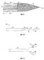
- the distal portion 44 and the proximal portion 42are of different, unequal lengths so that the dipole antenna 40 is unbalanced. In one embodiment, as shown in Fig. 7 , the distal portion 44 may be longer than the proximal portion 42.
- the proximal portion 42is formed from the inner conductor 50 and the inner insulator 52 which are extended outside the outer conductor 56, as shown best in Fig. 4 .
- the outer conductor 56 and the inner insulator 52may be sliced off to reveal the inner conductor 50, as shown in Fig. 5 .
- the distal portion 44includes a conductive member 45 that may be formed from any type of conductive material, such as metals (e.g., copper, stainless steel, tin, and various alloys thereof).
- the distal portion 44may have a solid structure and may be formed from solid wire (e.g., 10 AWG).
- the distal portion 44may be formed from a hollow sleeve of an outer conductor of coaxial cable or another cylindrical conductor.
- the cylindrical conductormay then be filled with solder to convert the cylinder into a solid shaft. More specifically, the solder may be heated to a temperature sufficient to liquefy the solder within the cylindrical conductor (e.g., 500°F) thereby creating a solid shaft.
- the proximal portion 42may also be formed from solid wire or a cylindrical conductor filled with solder.
- the proximal portion 42is thereafter coupled to the inner conductor 50, as shown in Fig. 4 . This may be accomplished by soldering the proximal portion 42 to the distal end of the inner conductor 50, such as by melting the solder of the proximal portion 42 and inserting the inner conductor 50 therein.
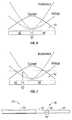
- the unbalanced dipole antenna 40provides for better impedance matching during ablation. Variation in tissue properties during ablation complicates real part impedance matching of microwave ablation antennas. Over the course of an ablation, a given position on the dipole varies in real impedance due to the resulting dynamic current and voltage relationship.
- Fig. 6shows the difficulty in matching real part impedance using a half-wave dipole antenna which includes two portions of equal lengths, at the center of the dipole the voltage is minimized and the current is maximized. However, the real part impedance is minimized and is maximized at the ends of the proximal and distal portions 42 and 44.
- the unbalanced dipole antenna 40 of the present disclosureminimizes the integration over ablation time of the difference between the feed point real part impedance and the impedance of the cable 16.
- the unbalanced half-wave dipoleprovides a better match of initial impedance to real part impedance by placing the gap between the proximal and distal portions 42 and 44 away from the center of the dipole antenna 40.
- the length of the distal portion 40is about 40 mm to minimize return loss of the assembly 12.
- Fig. 8illustrates the distal portion 44 attached to the proximal portion 42.
- the distal portion 44may be soldered to the inner conductor 50 of the proximal portion 42 to establish electromechanical contact therebetween.
- the distal portion 44may be attached to the proximal portion 42 by liquefying the solder of the distal portion 44 and inserting the distal end of the inner conductor 50 therein. A portion of the distal end of the inner conductor 50 is inserted into the distal portion 44 such that a dipole feed gap "G" remains between the proximal and distal portions 42 and 44 at the feed point 46.
- the gap “G”may be from about 1 mm to about 3 mm.
- the dipole feed gap of the antennais the first structure the coaxial field mode encounters upon transfer to free space. The gap therefore plays an important role in the return loss, or system-to-antenna impedance match.
- the gap "G”is thereafter filled with a dielectric material to form the dielectric spacer at the feed point 46.
- the inner insulator 52is extended into the feed point 46.
- the dielectric materialmay be polytetrafluoroethylene (PTFE), such as Teflon® sold by DuPont of Willmington, DE.
- PTFEpolytetrafluoroethylene
- the gap "G”may be coated via a dielectric seal coating as discussed in more detail below.
- the distal portion 44is coupled to the tip 48, which may be formed from a variety of heat-resistant materials suitable for penetrating tissue, such as metals (e.g., stainless steel) and various thermoplastic materials, such as poletherimide, polyamide thermoplastic resins, an example of which is Ultem® sold by General Electric Co. of Fairfield, CT.
- the tip 48may be machined from various stock rods to obtain a desired shape.
- the tip 48may be attached to the distal portion 44 using various adhesives, such as epoxy seal 49. If the tip 48 is metal, the tip 48 may be soldered to the distal portion 44.
- Fig. 11illustrates various shapes and forms of the tip 48, namely a stainless steel tip 48a and a dielectric tip 48b.
- Both tips 48a and 48bincludes an insertion base 51 having an external diameter that is smaller than diameter of the tips 48a and 49 allowing for easier insertion into the sheath 38. This configuration also provides for a better seal between the tip 48 and the sheath 38 as discussed in more detail below.
- the antenna assembly 12also includes a choke 60.
- the choke 60is disposed around the feedline 20 and includes an inner dielectric layer 62 and an outer conductive layer 64.
- the choke 60is a proximally positioned quarter-wave length shorted choke.
- the choke 60is implemented as a quarter-wave length shorted by using the outer conductive layer 64 around the outer conductor 56 of the feedline 20 separated by the dielectric layer.
- the choke 60is shorted to the outer conductor 56 of the feedline 20 at the proximal end of the choke 60 by soldering or other means.
- the dielectric layer 32is formed from a fluoropolymer, such as tetrafluorethylene, perfluorpropylene, and the like, and has a thickness of 0.005 inches.
- the outer conductive layer 34may be formed from a so-called "perfect conductor" material, such as a highly conductive metal (e.g., copper).
- the choke 60may be a quarter-wavelength shorted choke, a half-wavelength open choke, and inverted quarter-wavelength shorted choke or a gap cancellation choke.
- the choke 60confines the microwave energy from the generator 14 to the radiating portion 20 of the assembly 12, thereby limiting the microwave energy deposition zone length along the feedline 20.
- the choke 28provides high impedance to microwave energy conducted down the outside of the feedline 20, thereby limiting energy deposition to the end of the antenna.
- a shorted quarter-wave choke placed at the high impedance point of the proximal portion 42 on the antenna assembly 12confines antenna currents to the radiating section 18 of the assembly 12, reducing the length and maximizing the cross sectional diameter of ablations due to nearly spherical power dissipation zones.
- the dielectric of dielectric layer 62extends past the choke conductor layer 64 toward the distal end of the assembly 12, as shown in Fig. 10 .
- the dielectric layer 62may extend past the choke conductor layer 64 by about 6 mm.
- This extended dielectricimproves the performance of the choke 60 by placing a capacitance between the proximal portion 42 of the dipole and the outer surface of the choke conductor layer 64 thereby blocking currents from jumping onto the choke conductor layer 64.
- the capacitance formed by the dielectricis a high impedance barrier to microwave currents which would otherwise jump from the proximal portion 42 to the outer surface of the choke 60 near the entrance thereof, avoiding the choke structure completely. Instead, these currents are directed into the quarter-wave choke 60 by the capacitance, improving its effectiveness.
- the wavelength increase due to tissue desiccationcauses the high impedance point on the proximal portion 42 to move proximally along the assembly 12.
- An effective chokemust present high impedance at this variable point.
- the extended dielectriceffectively acts as a variable position choke, covering the range over which this point s Kunststoffs, maintaining choke effectiveness as long as the high impedance point of the proximal portion 42 stays within the extended dielectric boundaries.
- the dielectric layer 62may be extended to any length between the choke conductive layer 64 and the feed point 46.
- the dielectric layer 62may be formed by applying a dielectric shrink material, such as 5/64" thick PTFE shrink wrap to the outer conductor 56. Once the shrink wrap material is placed around the outer conductor 56, the material is heated so that the material melts and sets about the outer conductor 56. The heating may be accomplished by hot air blowers, which can provide a hot air stream of about 750° F. Multiple layers of the PTFE shrink wrap may be applied and consecutively heated to form the dielectric layer 62 of desired thickness. In one embodiment, three or more layers of the PTFE shrink wrap are applied.
- a dielectric shrink materialsuch as 5/64" thick PTFE shrink wrap
- the conductor layer 64may be formed by applying one or more layers of a conductive metal foil (e.g., copper) onto the dielectric layer 62.
- the foilmay extend past the proximal end of the dielectric layer 62 as shown in Fig. 12 .
- the foilmay be attached to the dielectric layer 62 using various types of adhesives (e.g., ultraviolet light activated glue, epoxy, etc.).
- the proximal end of the foil which extends past the dielectric layer 62may be attached to the feedline 20 by means of a so-called "wire-wrap" technique to provide a good electrical connection to the foil and the feedline 20 as shown in Fig. 12 .
- the wireis wrapped around the copper foil at the point where the foil begins to taper down past the dielectric layer 62. After the wire is wrapped, the wire is soldered to itself all along the length of the wrap to secure the wire and prevent the wire from unwrapping.
- other meansmay be used to secure the foil to the feedline 20, such as a hollow cylinder may be placed around the excess foil necking down past the dielectric layer 62.
- the foilmay be substantially the same length as the dielectric layer 62 to obviate the need for securing the proximal end of the foil to the feedline 20.
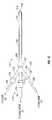
- the assembly 12also includes the connection hub 22, as shown in more detail in Fig. 13 .
- the connection hub 22includes a cable connector 79 and fluid ports 30 and 32.
- the connection hub 22may include a three-branch luer type connector 72, with a middle finger 74 being used to house the cable connector 70 and the left and right fingers 76 and 78 to house the outlet and inlet fluid ports 30 and 32, respectively.
- the connection hub 22also includes a base 81 disposed at a distal end of the middle finger 74.
- the assembly 12also includes an active coolant system as shown in Figs. 1 , 13 and 14 . More specifically, the assembly 12 includes sheath 38 that encloses the feedline 20, the radiating portion 18 from the tip 48 to the base 81. The coolant is supplied by the pump 34 and is circulated in the space between the radiating portion 18, the feedline 20 and the sheath 38. Since the radiating portion 18 and the feedline 20 are in direct contact with the coolant fluid these components of the assembly 12 should be sealed to prevent any fluid seeping therein. This may be accomplished by applying any type of melt-processible polymers using conventional injection molding and screw extrusion techniques.
- a sleeve of fluorinated ethylene propylene (FEP) shrink wrapmay be applied to the entire assembly 12, namely the feedline 20 and the radiating portion 18, as shown in Fig. 1 .
- the FEP sleeveis then heated to seal the feedline 20 and radiating portion 18.
- the resulting FEP sealprevents any coolant fluid from penetrating into the assembly 12.
- the FEP sleevemay be applied either prior to or after applying the outer conductive layer 64.
- FEPmay also be applied at the point where the inner conductor 50 and the inner insulator 52 are extended past the outer conductor 56, thereby creating a vacuum 53 as shown in Fig. 4 .
- the sheath 38may be any type of rigid tube, such as a catheter manufactured from polyimide and other types of polymers.
- the sheath 38may be assembled by initially securing the tip 48 to the distal end of the sheath 38 and then inserting the combined sheath and tip assembly onto the assembly 12.
- the sheath 38is also secured to the base 81 of the connection hub 22 and the tip 48 such that the sheath 38 is in fluid communication with the connection hub 22 and defines a chamber 89 between the base 81 and the tip 48.
- the inflow tube 86may include one or more inflow tubes 86a and 86b.
- the inflow tubes 86a and 86bmay be any type of flexible tube having an external diameter sufficient to fit inside the chamber 89 ( Figs. 4 and 9 ) between the feedline 20 and the sheath 38.
- the inflow tubes 86a and 86bare inserted through the outlet fluid port 30. More specifically, the inflow tube 86a is inserted almost to the distal end of the distal portion 44 and the inflow tube 86b is inserted approximately to the feed point 46 as shown in Fig. 14 .
- the inflow tubes 86a and 86bare then secured to the radiating portion 18 (e.g., using epoxy, glue, etc.).
- the inflow tubes 86a and 86bare positioned in this configuration to provide for optimal coolant flow through the sheath 38.
- the fluid flow from the inflow tube 86ais ejected into the tip 48 and is reflected in the proximal direction.
- the fluid flow from the inflow tube 86bprovides for the coolant along the radiating portion 18.
- the pump 34supplies fluid to the assembly 12 through the inflow tubes 86a and 86b, thereby circulating the coolant through the entire length of the assembly 12 including the connection hub 22.
- the fluidis then withdrawn from the middle finger 74 and the left finger 76 through the outlet fluid port 32.
- the above-discussed coolant systemprovides for circulation of dielectric coolant fluid (e.g., saline, deionized water, etc.) through the entire length of the antenna assembly 12.
- the dielectric coolant fluidremoves the heat generated by the assembly 12.
- the dielectric coolant fluidacts as a buffer for the assembly 12 and prevents near field dielectric properties of the assembly 12 from changing due varying tissue dielectric properties.
- desiccation of the tissue around the radiating portion 18results in a drop in tissue complex permittivity by a considerable factor (e.g., about 10).
- the dielectric constant (er') dropincreases the wavelength of microwave energy in the tissue, which dramatically affects the impedance of un-buffered microwave antenna assemblies, thereby mismatching the antenna assemblies from the system impedance (e.g., impedance of the cable 16 and the generator 14).
- the increase in wavelengthalso results in a power dissipation zone which is much longer in length along the assembly 12 than in cross sectional diameter.
- the decrease in tissue conductivity (er")also affects the real part of the impedance of the assembly 12.
- the fluid dielectric buffering according to the present disclosurealso moderates the increase in wavelength of the delivered energy and drop in conductivity of the near field, thereby reducing the change in impedance of the assembly 12, allowing for more consistent antenna-to-system impedance match and spherical power dissipation zone despite tissue behavior.
- the buffering of wavelength variationalso allows for a more effective choking network.
- the chokemust be placed at the low current point, or high impedance point, on the end of the proximal portion 42. With wavelength buffering in the choked wet tip, the half wavelength current pattern on the dipole radiating section is maintained, making the position of the high impedance point less variable and therefore allowing for a more effective choke network.
- the cable cooling and the dielectric bufferingallow for targeted and efficient energy delivery to the tissue to enable nearly spherical ablation zones and fast ablation times. Either saline or deionized water can be used with the assembly 12.
- Figs. 15-18illustrate another embodiment of a microwave antenna assembly 112 of having a radiating portion 118 and a feedline 120 which couples the assembly 112 to the cable 16. More specifically, the antenna assembly 112 is coupled to the cable 16 through a connection hub 122 that includes an outlet fluid port 130 and an inlet fluid port 132.
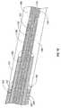
- Figs. 16 and 17illustrate the radiating portion 118 of the antenna assembly 112 having an unbalanced dipole antenna 140 in which the sheath 38 is replaced by a metallic conduit (e.g., coolant jacket 200) and a solid dielectric loading 190.
- the dipole antenna 140is coupled to the feedline 120, which electrically connects antenna assembly 112 to the generator 14.
- the feedline 120includes an inner conductor 150 (e.g., wire) surrounded by an inner 152 insulator which is then surrounded by an outer conductor 156 (e.g., cylindrical conducting sheath).
- the dipole antenna 140includes a proximal portion 142 and a distal portion 144 interconnected by a dielectric spacer at a feed point 146.
- the distal portion 144includes a conductive member 145.
- the distal portion 144 and the proximal portion 142are of different, unequal lengths so that the dipole antenna 40 is unbalanced.
- the proximal portion 142is formed from the inner conductor 150 and the inner insulator 152 which are extended outside the outer conductor 156.
- the outer conductor 156 and the inner insulator 152may be sliced off to reveal the inner conductor 150 as shown in Fig. 18 .
- the distal portion 144may be formed from any type of conductive material such as metals (e.g., copper, stainless steel, tin, and various alloys thereof.
- the portion 144may have a solid structure and may be formed from solid wire (e.g., 10 AWG) or a cylindrical conductor filled with solder similar to the portion 44 of the assembly 12.
- the proximal portion 144is thereafter coupled to the inner conductor 150.
- the antenna assembly 112also includes a choke 160.
- the choke 160is disposed around the feedline 120 and includes an inner dielectric layer 162 and an outer conductive layer 164.
- the choke 160is a proximally positioned quarter-wave shorted choke that is shorted to the outer conductor 156 of the feedline 120 at the proximal end of the choke 160 by soldering or other means.
- the dielectric of dielectric layer 162extends past the choke conductor layer 164 toward the distal end of the assembly 112.
- the assembly 112also includes the connection hub 122, as shown in Figs. 15 .
- the connection hub 122includes a cable connector 179 and the fluid ports 130 and 132.
- the connection hub 122may include a three-branch luer type connector 172, with a middle finger 174 being used to house the cable connector 179 and the left and right fingers 176 and 178 to house the outlet and inlet fluid ports 130 and 132, respectively.
- the cable connector 179is coupled to the inner conductor 152 and outer conductor 156 that are extended outside the outer conductor 156 at the proximal end of the feedline 120.
- the connection hub 122also includes a base 181 disposed at a distal end of the middle finger 174.
- the assembly 112includes one or more inflow tubes 186 which are fed through the right finger 178.
- the assembly 112includes a solid dielectric loading 190 disposed over the dipole antenna 140 replacing the liquid dielectric material of assembly 112.
- the solid dielectric loading 190extend from the point of termination of the choke conductor layer 164. More specifically, the assembly 112 includes a fluid seal 192 over the distal end of the choke conductor layer 164.
- the loading 190may be attached to the seal 192 via glue and other means.
- the loading 190may be cylinder-shaped having a central cavity 198 defined therein suitable for insertion over the antenna 140.
- the loading 190may also have a tapered end 194 with a pointed tip 196, thereby obviating the need for the tip 48.
- the loading 190may also be attached to the distal end of the antenna 140 (e.g., at the distal portion 144 thereof) within the cavity 198.
- the cavity 198may have a substantially cylindrical shape suitable to fit over the antenna 140 depending on the cross-sectional shape thereof.
- the cavity 198includes a proximal portion 197 and a distal portion 199 with the proximal portion 197 having a larger inner diameter than the distal portion 199 to accommodate the choke dielectric layer 162.
- the choke layer 162may be extended to any length between the choke conductive layer 164 and the feed point 146. To accommodate the extended choke layer 162 the depth of the proximal portion 197 varies accordingly.
- the loading 190has an outer diameter being substantially equal to the thickness of the feedline 120 and the inner diameter being substantially equal to the diameter of the dipole antenna 140. Since the loading 190 is disposed on the dipole antenna 140 and no coolant fluid is going to be in contact therewith, the antenna 140 may not be coated in dielectric shrink wrap to seal its components.
- the dielectric material of the loading 90may have a dielectric constant of from about 2.5 and 150 and may be made from a ceramic material, such as alumina ceramic or a plastic material, such as a polyamide plastic (e.g., VESPEL® available from DuPont of Wilmington, Delaware).
- the loading 190acts as a dielectric buffer between the radiating portion 118 and the tissue so that as the electrical properties of the tissue change during ablation the antenna assembly 112 remains halfwave resonant and impedance-matched to the energy delivery system (e.g., the generator 14, the cable 16, etc.) throughout the ablation.
- the energy delivery systeme.g., the generator 14, the cable 16, etc.
- the antenna assembly 112also includes a coolant jacket 200 disposed between the base 181 and the seal 192.
- the coolant jacket 200maybe formed from stainless steel or other suitable medical grade metals.
- the coolant jacket 200defines a proximal chamber 201 between the choke conductor layer 164 and the coolant jacket 200 into which a dielectric coolant fluid is supplied through the connection hub 122. More specifically, one or more inflow tube 186 similar to the tubes 86a and 86b may extend into the chamber 201 to circulate the dielectric coolant fluid through the coolant jacket 200.
- the seal 192is disposed between the coolant jacket 200 and the choke conductor layer 164 at the distal ends thereof.
- the seal 192may be formed from any type of dielectric (e.g., elastomer) and/or conductive material suitable for sealing the chamber 201 from the loading 190.
Landscapes
- Health & Medical Sciences (AREA)
- Surgery (AREA)
- Life Sciences & Earth Sciences (AREA)
- Biomedical Technology (AREA)
- Medical Informatics (AREA)
- Nuclear Medicine, Radiotherapy & Molecular Imaging (AREA)
- Electromagnetism (AREA)
- Engineering & Computer Science (AREA)
- Physics & Mathematics (AREA)
- Heart & Thoracic Surgery (AREA)
- Otolaryngology (AREA)
- Molecular Biology (AREA)
- Animal Behavior & Ethology (AREA)
- General Health & Medical Sciences (AREA)
- Public Health (AREA)
- Veterinary Medicine (AREA)
- Surgical Instruments (AREA)
- Details Of Aerials (AREA)
Description
- This application claims the benefit of priority to
U.S. Provisional Application Serial No. 61/023,031 - The present disclosure relates generally to microwave applicators used in tissue ablation procedures. More particularly, the present disclosure is directed to a microwave applicator having either a liquid or solid loaded tip dipole antenna.
- Treatment of certain diseases requires destruction of malignant tissue growths (e.g., tumors). It is known that tumor cells denature at elevated temperatures that are slightly lower than temperatures injurious to surrounding healthy cells. Therefore, known treatment methods, such as hyperthermia therapy, heat tumor cells to temperatures above 41° C, while maintaining adjacent healthy cells at lower temperatures to avoid irreversible cell damage. Such methods involve applying electromagnetic radiation to heat tissue and include ablation and coagulation of tissue. In particular, microwave energy is used to coagulate and/or ablate tissue to denature or kill the cancerous cells.
- Microwave energy is applied via microwave ablation antennas that penetrate tissue to reach tumors. There are several types of microwave antennas, such as monopole and dipole. In monopole and dipole antennas, microwave energy radiates perpendicularly from the axis of the conductor. A monopole antenna includes a single, elongated microwave conductor. Dipole antennas may have a coaxial construction including an inner conductor and an outer conductor separated by a dielectric portion. More specifically, dipole microwave antennas may have a long, thin inner conductor that extends along a longitudinal axis of the antenna and is surrounded by an outer conductor. In certain variations, a portion or portions of the outer conductor may be selectively removed to provide for more effective outward radiation of energy. This type of microwave antenna construction is typically referred to as a "leaky waveguide" or "leaky coaxial" antenna.
- Conventional microwave antennas have a narrow operational bandwidth, a wavelength range at which optimal operational efficiency is achieved, and hence, are incapable of maintaining a predetermined impedance match between the microwave delivery system (e.g., generator, cable, etc.) and the tissue surrounding the microwave antenna. More specifically, as microwave energy is applied to tissue, the dielectric constant of the tissue immediately surrounding the microwave antenna decreases as the tissue is cooked. The drop causes the wavelength of the microwave energy being applied to tissue to increase beyond the bandwidth of the antenna. As a result, there is a mismatch between the bandwidth of conventional microwave antenna and the microwave energy being applied. Thus, narrow band microwave antennas may detune hindering effective energy delivery and dispersion.
- According to one aspect of the present disclosure a microwave antenna assembly is disclosed. The antenna assembly includes an unbalanced dipole antenna, a shorted choke having a dielectric layer extending past the conductor layer and connection hub coupled to a coolant system for circulating a dielectric coolant fluid through the antenna assembly.
- According to another aspect of the present disclosure a microwave antenna assembly is disclosed. The antenna assembly includes a feedline having an inner conductor, an outer conductor and an inner insulator disposed therebetween. A radiating portion is included which has an unbalanced dipole antenna having a proximal portion and a distal portion that is longer than the proximal portion. The proximal portion includes at least a portion of the inner conductor and the inner insulator and the distal portion includes a conductive member. The antenna assembly also includes a choke disposed around at least a portion of the feedline. The choke includes an inner dielectric layer and an outer conductive layer, wherein the outer conductive layer is shorted to the outer conductor of the feedline and the inner dielectric layer extends past the outer conductive layer. The assembly further includes a sheath disposed over the feedline and the radiating portion, the sheath defines a chamber around the feedline and the radiating portion, the chamber being adapted to circulate dielectric coolant fluid therethrough.
- According to a further aspect of the present disclosure a microwave antenna assembly is disclosed. The antenna assembly includes a feedline having an inner conductor, an outer conductor and an inner insulator disposed therebetween and a radiating portion including an unbalanced dipole antenna having a proximal portion and a distal portion that are of different lengths. The proximal portion includes at least a portion of the inner conductor and the inner insulator and the distal portion includes a conductive member. The antenna assembly also includes a choke disposed around at least a portion of the feedline. The choke includes an inner dielectric layer and an outer conductive layer, wherein the outer conductive layer is shorted to the outer conductor of the feedline and the inner dielectric layer extends past the outer conductive layer. The antenna assembly further includes a coolant jacket disposed over the feedline defining a proximal chamber around the feedline, the chamber being adapted to circulate dielectric coolant fluid therethrough and a solid dielectric loading having central cavity defined therein adapted to fit about the radiating portion, the solid dielectric loading extending from the coolant jacket.
- The above and other aspects, features, and advantages of the present disclosure will become more apparent in light of the following detailed description when taken in conjunction with the accompanying drawings in which:
Fig. 1 is a schematic diagram of a microwave ablation system according to an embodiment of the present disclosure;Fig. 2 is a perspective cross-sectional view of a microwave antenna assembly according to the present disclosure;Fig. 3 is an enlarged cross-sectional of a portion of the microwave antenna assembly ofFig. 2 ;Fig. 4 is an enlarged cross-sectional of a portion of the microwave antenna assembly ofFig. 2 ;Fig. 5 is a side view of a distal portion of a feedline of the microwave antenna assembly ofFig. 2 ;Fig. 6 is a schematic illustration of a balanced dipole antenna according to an embodiment of the present disclosure;Fig. 7 is a schematic illustration of an unbalanced dipole antenna according to an embodiment of the present disclosure;Fig. 8 is a side view of the unbalanced dipole antenna of the microwave antenna assembly ofFig. 2 ;Fig. 9 is an enlarged cross-sectional of a distal end of the microwave antenna assembly ofFig. 2 ;Fig. 10 is a side view of a radiating portion of the microwave antenna assembly ofFig. 2 ;Fig. 11 is a side view of a tip and a sheath of the microwave antenna assembly ofFig. 2 ;Fig. 12 is a side view of is proximal end of the feedline of the microwave antenna assembly ofFig. 2 ;Fig. 13 is a cross-sectional view of the connection hub and a proximal end f the microwave antenna assembly ofFig. 2 ;Fig. 14 is a schematic view of inflow tubes of the microwave antenna assembly ofFig. 2 ;Fig. 15 is a side view of a microwave antenna assembly according to one embodiment of the present disclosure;Figs. 16 and 17 are perspective cross-sectional views of the microwave antenna ofFig. 15 ; andFig. 18 is a cross-sectional enlarged perspective view of the microwave antenna ofFig. 15 .- Particular embodiments of the present disclosure will be described herein below with reference to the accompanying drawings. In the following description, well-known functions or constructions are not described in detail to avoid obscuring the present disclosure in unnecessary detail.
Fig.1 shows amicrowave ablation system 10 that includes amicrowave antenna assembly 12 coupled to amicrowave generator 14 via a flexiblecoaxial cable 16. Thegenerator 14 is configured to provide microwave energy at an operational frequency from about 500 MHz to about 5000 MHz.- The
antenna assembly 12 is generally comprised of radiatingportion 18, which may be connected by feedline 20 (or shaft) to thecable 16. More specifically, theantenna assembly 12 is coupled to thecable 16 through aconnection hub 22. Theconnection hub 22 also includes anoutlet fluid port 30 and aninlet fluid port 32 that are connected in fluid communication with asheath 38. Thesheath 38 encloses the radiatingportion 18 and thefeedline 20 allowing for coolant fluid from theports antenna assembly 12. Theports supply pump 34 that is, in turn, coupled to asupply tank 36. Thesupply tank 36 stores the coolant fluid and maintains the fluid at a predetermined temperature. In one embodiment, thesupply tank 36 may include a coolant unit which cools the returning liquid from theantenna assembly 12. In another embodiment, the coolant fluid may be a gas and/or a mixture of fluid and gas. Assembly 12 also includes atip 48 having atapered end 24 that terminates, in one embodiment, at apointed end 26 to allow for insertion into tissue with minimal resistance at a distal end of the radiatingportion 18. In those cases where the radiatingportion 18 is inserted into a pre-existing opening,tip 48 may be rounded or flat.Fig. 2 illustrates the radiatingportion 18 of theantenna assembly 12 having anunbalanced dipole antenna 40. Thedipole antenna 40 is coupled to thefeedline 20 that electrically connectsantenna assembly 12 to thegenerator 14. As shown inFig. 3-4 , thefeedline 20 includes an inner conductor 50 (e.g., wire) surrounded by aninner insulator 52, which is then surrounded by an outer conductor 56 (e.g., cylindrical conducting sheath). The inner and outer conductors may be constructed of copper, gold, stainless steel or other conductive metals with similar conductivity values. The metals may be plated with other materials, e.g., other conductive materials, to improve their properties, e.g., to improve conductivity or decrease energy loss, etc. In one embodiment, thefeedline 20 may be formed from a coaxial semi-rigid or flexible cable having a wire with a 0.047" outer diameter rated for 50 Ohms.- The
dipole antenna 40 includes aproximal portion 42 and adistal portion 44 interconnected by a dielectric spacer at afeed point 46. Thedistal portion 44 and theproximal portion 42 are of different, unequal lengths so that thedipole antenna 40 is unbalanced. In one embodiment, as shown inFig. 7 , thedistal portion 44 may be longer than theproximal portion 42. Theproximal portion 42 is formed from theinner conductor 50 and theinner insulator 52 which are extended outside theouter conductor 56, as shown best inFig. 4 . In one embodiment, in which thefeedline 20 is formed from a coaxial cable, theouter conductor 56 and theinner insulator 52 may be sliced off to reveal theinner conductor 50, as shown inFig. 5 . - The
distal portion 44 includes aconductive member 45 that may be formed from any type of conductive material, such as metals (e.g., copper, stainless steel, tin, and various alloys thereof). Thedistal portion 44 may have a solid structure and may be formed from solid wire (e.g., 10 AWG). In another embodiment, thedistal portion 44 may be formed from a hollow sleeve of an outer conductor of coaxial cable or another cylindrical conductor. The cylindrical conductor may then be filled with solder to convert the cylinder into a solid shaft. More specifically, the solder may be heated to a temperature sufficient to liquefy the solder within the cylindrical conductor (e.g., 500°F) thereby creating a solid shaft. - In another embodiment, the
proximal portion 42 may also be formed from solid wire or a cylindrical conductor filled with solder. Theproximal portion 42 is thereafter coupled to theinner conductor 50, as shown inFig. 4 . This may be accomplished by soldering theproximal portion 42 to the distal end of theinner conductor 50, such as by melting the solder of theproximal portion 42 and inserting theinner conductor 50 therein. - In some embodiments, the
unbalanced dipole antenna 40 provides for better impedance matching during ablation. Variation in tissue properties during ablation complicates real part impedance matching of microwave ablation antennas. Over the course of an ablation, a given position on the dipole varies in real impedance due to the resulting dynamic current and voltage relationship.Fig. 6 shows the difficulty in matching real part impedance using a half-wave dipole antenna which includes two portions of equal lengths, at the center of the dipole the voltage is minimized and the current is maximized. However, the real part impedance is minimized and is maximized at the ends of the proximal anddistal portions unbalanced dipole antenna 40 of the present disclosure minimizes the integration over ablation time of the difference between the feed point real part impedance and the impedance of thecable 16. As illustrated inFig. 7 , the unbalanced half-wave dipole provides a better match of initial impedance to real part impedance by placing the gap between the proximal anddistal portions dipole antenna 40. In one embodiment, the length of thedistal portion 40 is about 40 mm to minimize return loss of theassembly 12. Fig. 8 illustrates thedistal portion 44 attached to theproximal portion 42. Thedistal portion 44 may be soldered to theinner conductor 50 of theproximal portion 42 to establish electromechanical contact therebetween. In one embodiment, where thedistal portion 44 is formed from a hollow cylindrical conductor filled with a solder material, thedistal portion 44 may be attached to theproximal portion 42 by liquefying the solder of thedistal portion 44 and inserting the distal end of theinner conductor 50 therein. A portion of the distal end of theinner conductor 50 is inserted into thedistal portion 44 such that a dipole feed gap "G" remains between the proximal anddistal portions feed point 46. The gap "G" may be from about 1 mm to about 3 mm. The dipole feed gap of the antenna is the first structure the coaxial field mode encounters upon transfer to free space. The gap therefore plays an important role in the return loss, or system-to-antenna impedance match. In one embodiment, the gap "G" is thereafter filled with a dielectric material to form the dielectric spacer at thefeed point 46. In another embodiment, theinner insulator 52 is extended into thefeed point 46. The dielectric material may be polytetrafluoroethylene (PTFE), such as Teflon® sold by DuPont of Willmington, DE. In another embodiment, as shown inFig. 4 , the gap "G" may be coated via a dielectric seal coating as discussed in more detail below.- As shown in
Figs. 2 and9 , thedistal portion 44 is coupled to thetip 48, which may be formed from a variety of heat-resistant materials suitable for penetrating tissue, such as metals (e.g., stainless steel) and various thermoplastic materials, such as poletherimide, polyamide thermoplastic resins, an example of which is Ultem® sold by General Electric Co. of Fairfield, CT. Thetip 48 may be machined from various stock rods to obtain a desired shape. Thetip 48 may be attached to thedistal portion 44 using various adhesives, such asepoxy seal 49. If thetip 48 is metal, thetip 48 may be soldered to thedistal portion 44. Fig. 11 illustrates various shapes and forms of thetip 48, namely astainless steel tip 48a and adielectric tip 48b. Bothtips insertion base 51 having an external diameter that is smaller than diameter of thetips sheath 38. This configuration also provides for a better seal between thetip 48 and thesheath 38 as discussed in more detail below.- With reference to
Figs. 2 and 3 , theantenna assembly 12 also includes achoke 60. Thechoke 60 is disposed around thefeedline 20 and includes aninner dielectric layer 62 and an outerconductive layer 64. In one embodiment, thechoke 60 is a proximally positioned quarter-wave length shorted choke. Thechoke 60 is implemented as a quarter-wave length shorted by using the outerconductive layer 64 around theouter conductor 56 of thefeedline 20 separated by the dielectric layer. Thechoke 60 is shorted to theouter conductor 56 of thefeedline 20 at the proximal end of thechoke 60 by soldering or other means. In one embodiment, thedielectric layer 32 is formed from a fluoropolymer, such as tetrafluorethylene, perfluorpropylene, and the like, and has a thickness of 0.005 inches. The outerconductive layer 34 may be formed from a so-called "perfect conductor" material, such as a highly conductive metal (e.g., copper). - In embodiments, the
choke 60 may be a quarter-wavelength shorted choke, a half-wavelength open choke, and inverted quarter-wavelength shorted choke or a gap cancellation choke. Thechoke 60 confines the microwave energy from thegenerator 14 to the radiatingportion 20 of theassembly 12, thereby limiting the microwave energy deposition zone length along thefeedline 20. The choke 28 provides high impedance to microwave energy conducted down the outside of thefeedline 20, thereby limiting energy deposition to the end of the antenna. - A shorted quarter-wave choke placed at the high impedance point of the
proximal portion 42 on theantenna assembly 12 confines antenna currents to the radiatingsection 18 of theassembly 12, reducing the length and maximizing the cross sectional diameter of ablations due to nearly spherical power dissipation zones. - The dielectric of
dielectric layer 62 extends past thechoke conductor layer 64 toward the distal end of theassembly 12, as shown inFig. 10 . In one embodiment, thedielectric layer 62 may extend past thechoke conductor layer 64 by about 6 mm. This extended dielectric improves the performance of thechoke 60 by placing a capacitance between theproximal portion 42 of the dipole and the outer surface of thechoke conductor layer 64 thereby blocking currents from jumping onto thechoke conductor layer 64. The capacitance formed by the dielectric is a high impedance barrier to microwave currents which would otherwise jump from theproximal portion 42 to the outer surface of thechoke 60 near the entrance thereof, avoiding the choke structure completely. Instead, these currents are directed into the quarter-wave choke 60 by the capacitance, improving its effectiveness. - As discussed above, the wavelength increase due to tissue desiccation causes the high impedance point on the
proximal portion 42 to move proximally along theassembly 12. An effective choke must present high impedance at this variable point. The extended dielectric effectively acts as a variable position choke, covering the range over which this point slufts, maintaining choke effectiveness as long as the high impedance point of theproximal portion 42 stays within the extended dielectric boundaries. Thedielectric layer 62 may be extended to any length between the chokeconductive layer 64 and thefeed point 46. - In one embodiment, the
dielectric layer 62 may be formed by applying a dielectric shrink material, such as 5/64" thick PTFE shrink wrap to theouter conductor 56. Once the shrink wrap material is placed around theouter conductor 56, the material is heated so that the material melts and sets about theouter conductor 56. The heating may be accomplished by hot air blowers, which can provide a hot air stream of about 750° F. Multiple layers of the PTFE shrink wrap may be applied and consecutively heated to form thedielectric layer 62 of desired thickness. In one embodiment, three or more layers of the PTFE shrink wrap are applied. - As shown in
Figs. 3 and10 , theconductor layer 64 may be formed by applying one or more layers of a conductive metal foil (e.g., copper) onto thedielectric layer 62. The foil may extend past the proximal end of thedielectric layer 62 as shown inFig. 12 . The foil may be attached to thedielectric layer 62 using various types of adhesives (e.g., ultraviolet light activated glue, epoxy, etc.). In one embodiment, the proximal end of the foil which extends past thedielectric layer 62 may be attached to thefeedline 20 by means of a so-called "wire-wrap" technique to provide a good electrical connection to the foil and thefeedline 20 as shown inFig. 12 . The wire is wrapped around the copper foil at the point where the foil begins to taper down past thedielectric layer 62. After the wire is wrapped, the wire is soldered to itself all along the length of the wrap to secure the wire and prevent the wire from unwrapping. In another embodiment, other means may be used to secure the foil to thefeedline 20, such as a hollow cylinder may be placed around the excess foil necking down past thedielectric layer 62. In a further embodiment, the foil may be substantially the same length as thedielectric layer 62 to obviate the need for securing the proximal end of the foil to thefeedline 20. - The
assembly 12 also includes theconnection hub 22, as shown in more detail inFig. 13 . Theconnection hub 22 includes acable connector 79 andfluid ports connection hub 22 may include a three-branchluer type connector 72, with a middle finger 74 being used to house the cable connector 70 and the left andright fingers inlet fluid ports connection hub 22 also includes a base 81 disposed at a distal end of the middle finger 74. - The
assembly 12 also includes an active coolant system as shown inFigs. 1 ,13 and 14 . More specifically, theassembly 12 includessheath 38 that encloses thefeedline 20, the radiatingportion 18 from thetip 48 to thebase 81. The coolant is supplied by thepump 34 and is circulated in the space between the radiatingportion 18, thefeedline 20 and thesheath 38. Since the radiatingportion 18 and thefeedline 20 are in direct contact with the coolant fluid these components of theassembly 12 should be sealed to prevent any fluid seeping therein. This may be accomplished by applying any type of melt-processible polymers using conventional injection molding and screw extrusion techniques. In one embodiment, a sleeve of fluorinated ethylene propylene (FEP) shrink wrap may be applied to theentire assembly 12, namely thefeedline 20 and the radiatingportion 18, as shown inFig. 1 . The FEP sleeve is then heated to seal thefeedline 20 and radiatingportion 18. The resulting FEP seal prevents any coolant fluid from penetrating into theassembly 12. The FEP sleeve may be applied either prior to or after applying the outerconductive layer 64. In addition, FEP may also be applied at the point where theinner conductor 50 and theinner insulator 52 are extended past theouter conductor 56, thereby creating avacuum 53 as shown inFig. 4 . - The
sheath 38 may be any type of rigid tube, such as a catheter manufactured from polyimide and other types of polymers. Thesheath 38 may be assembled by initially securing thetip 48 to the distal end of thesheath 38 and then inserting the combined sheath and tip assembly onto theassembly 12. Thesheath 38 is also secured to thebase 81 of theconnection hub 22 and thetip 48 such that thesheath 38 is in fluid communication with theconnection hub 22 and defines achamber 89 between the base 81 and thetip 48. - The
inflow tube 86 may include one ormore inflow tubes inflow tubes Figs. 4 and9 ) between thefeedline 20 and thesheath 38. Theinflow tubes outlet fluid port 30. More specifically, theinflow tube 86a is inserted almost to the distal end of thedistal portion 44 and theinflow tube 86b is inserted approximately to thefeed point 46 as shown inFig. 14 . Theinflow tubes inflow tubes sheath 38. The fluid flow from theinflow tube 86a is ejected into thetip 48 and is reflected in the proximal direction. The fluid flow from theinflow tube 86b provides for the coolant along the radiatingportion 18. During operation, thepump 34 supplies fluid to theassembly 12 through theinflow tubes assembly 12 including theconnection hub 22. The fluid is then withdrawn from the middle finger 74 and theleft finger 76 through theoutlet fluid port 32. - The above-discussed coolant system provides for circulation of dielectric coolant fluid (e.g., saline, deionized water, etc.) through the entire length of the
antenna assembly 12. The dielectric coolant fluid removes the heat generated by theassembly 12. In addition, the dielectric coolant fluid acts as a buffer for theassembly 12 and prevents near field dielectric properties of theassembly 12 from changing due varying tissue dielectric properties. As microwave energy is applied during ablation, desiccation of the tissue around the radiatingportion 18 results in a drop in tissue complex permittivity by a considerable factor (e.g., about 10). The dielectric constant (er') drop increases the wavelength of microwave energy in the tissue, which dramatically affects the impedance of un-buffered microwave antenna assemblies, thereby mismatching the antenna assemblies from the system impedance (e.g., impedance of thecable 16 and the generator 14). The increase in wavelength also results in a power dissipation zone which is much longer in length along theassembly 12 than in cross sectional diameter. The decrease in tissue conductivity (er") also affects the real part of the impedance of theassembly 12. The fluid dielectric buffering according to the present disclosure also moderates the increase in wavelength of the delivered energy and drop in conductivity of the near field, thereby reducing the change in impedance of theassembly 12, allowing for more consistent antenna-to-system impedance match and spherical power dissipation zone despite tissue behavior. - The buffering of wavelength variation also allows for a more effective choking network. The choke must be placed at the low current point, or high impedance point, on the end of the
proximal portion 42. With wavelength buffering in the choked wet tip, the half wavelength current pattern on the dipole radiating section is maintained, making the position of the high impedance point less variable and therefore allowing for a more effective choke network. Together, the cable cooling and the dielectric buffering allow for targeted and efficient energy delivery to the tissue to enable nearly spherical ablation zones and fast ablation times. Either saline or deionized water can be used with theassembly 12. Figs. 15-18 illustrate another embodiment of amicrowave antenna assembly 112 of having a radiatingportion 118 and afeedline 120 which couples theassembly 112 to thecable 16. More specifically, theantenna assembly 112 is coupled to thecable 16 through aconnection hub 122 that includes anoutlet fluid port 130 and aninlet fluid port 132.Figs. 16 and 17 illustrate the radiatingportion 118 of theantenna assembly 112 having anunbalanced dipole antenna 140 in which thesheath 38 is replaced by a metallic conduit (e.g., coolant jacket 200) and asolid dielectric loading 190. Thedipole antenna 140 is coupled to thefeedline 120, which electrically connectsantenna assembly 112 to thegenerator 14. As shown inFig. 18 , similar to thefeedline 20, thefeedline 120 includes an inner conductor 150 (e.g., wire) surrounded by an inner 152 insulator which is then surrounded by an outer conductor 156 (e.g., cylindrical conducting sheath).- The
dipole antenna 140 includes aproximal portion 142 and adistal portion 144 interconnected by a dielectric spacer at afeed point 146. Thedistal portion 144 includes aconductive member 145. Thedistal portion 144 and theproximal portion 142 are of different, unequal lengths so that thedipole antenna 40 is unbalanced. Theproximal portion 142 is formed from theinner conductor 150 and theinner insulator 152 which are extended outside theouter conductor 156. In one embodiment, in which thefeedline 120 is formed from a coaxial cable, theouter conductor 156 and theinner insulator 152 may be sliced off to reveal theinner conductor 150 as shown inFig. 18 . - The
distal portion 144 may be formed from any type of conductive material such as metals (e.g., copper, stainless steel, tin, and various alloys thereof. Theportion 144 may have a solid structure and may be formed from solid wire (e.g., 10 AWG) or a cylindrical conductor filled with solder similar to theportion 44 of theassembly 12. Theproximal portion 144 is thereafter coupled to theinner conductor 150. - With reference to
Figs. 16-18 , theantenna assembly 112 also includes achoke 160. Thechoke 160 is disposed around thefeedline 120 and includes aninner dielectric layer 162 and an outerconductive layer 164. In one embodiment, thechoke 160 is a proximally positioned quarter-wave shorted choke that is shorted to theouter conductor 156 of thefeedline 120 at the proximal end of thechoke 160 by soldering or other means. The dielectric ofdielectric layer 162 extends past thechoke conductor layer 164 toward the distal end of theassembly 112. - The
assembly 112 also includes theconnection hub 122, as shown inFigs. 15 . Theconnection hub 122 includes acable connector 179 and thefluid ports connection hub 122 may include a three-branchluer type connector 172, with amiddle finger 174 being used to house thecable connector 179 and the left andright fingers inlet fluid ports cable connector 179 is coupled to theinner conductor 152 andouter conductor 156 that are extended outside theouter conductor 156 at the proximal end of thefeedline 120. Theconnection hub 122 also includes a base 181 disposed at a distal end of themiddle finger 174. In one embodiment, theassembly 112 includes one ormore inflow tubes 186 which are fed through theright finger 178. - The
assembly 112 includes asolid dielectric loading 190 disposed over thedipole antenna 140 replacing the liquid dielectric material ofassembly 112. Thesolid dielectric loading 190 extend from the point of termination of thechoke conductor layer 164. More specifically, theassembly 112 includes afluid seal 192 over the distal end of thechoke conductor layer 164. In one embodiment, theloading 190 may be attached to theseal 192 via glue and other means. - The
loading 190 may be cylinder-shaped having acentral cavity 198 defined therein suitable for insertion over theantenna 140. Theloading 190 may also have atapered end 194 with apointed tip 196, thereby obviating the need for thetip 48. Theloading 190 may also be attached to the distal end of the antenna 140 (e.g., at thedistal portion 144 thereof) within thecavity 198. Thecavity 198 may have a substantially cylindrical shape suitable to fit over theantenna 140 depending on the cross-sectional shape thereof. In addition, thecavity 198 includes aproximal portion 197 and adistal portion 199 with theproximal portion 197 having a larger inner diameter than thedistal portion 199 to accommodate thechoke dielectric layer 162. Thechoke layer 162 may be extended to any length between the chokeconductive layer 164 and thefeed point 146. To accommodate theextended choke layer 162 the depth of theproximal portion 197 varies accordingly. - The
loading 190 has an outer diameter being substantially equal to the thickness of thefeedline 120 and the inner diameter being substantially equal to the diameter of thedipole antenna 140. Since theloading 190 is disposed on thedipole antenna 140 and no coolant fluid is going to be in contact therewith, theantenna 140 may not be coated in dielectric shrink wrap to seal its components. - In one embodiment, the dielectric material of the loading 90 may have a dielectric constant of from about 2.5 and 150 and may be made from a ceramic material, such as alumina ceramic or a plastic material, such as a polyamide plastic (e.g., VESPEL® available from DuPont of Wilmington, Delaware). The loading 190 acts as a dielectric buffer between the radiating
portion 118 and the tissue so that as the electrical properties of the tissue change during ablation theantenna assembly 112 remains halfwave resonant and impedance-matched to the energy delivery system (e.g., thegenerator 14, thecable 16, etc.) throughout the ablation. - The
antenna assembly 112 also includes acoolant jacket 200 disposed between the base 181 and theseal 192. Thecoolant jacket 200 maybe formed from stainless steel or other suitable medical grade metals. Thecoolant jacket 200 defines aproximal chamber 201 between thechoke conductor layer 164 and thecoolant jacket 200 into which a dielectric coolant fluid is supplied through theconnection hub 122. More specifically, one ormore inflow tube 186 similar to thetubes chamber 201 to circulate the dielectric coolant fluid through thecoolant jacket 200. Theseal 192 is disposed between thecoolant jacket 200 and thechoke conductor layer 164 at the distal ends thereof. Theseal 192 may be formed from any type of dielectric (e.g., elastomer) and/or conductive material suitable for sealing thechamber 201 from theloading 190. - The described embodiments of the present disclosure are intended to be illustrative rather than restrictive, and are not intended to represent every embodiment of the present disclosure. Various modifications and variations can be made without departing from the scope of the disclosure as set forth in the following claims both literally and in equivalents recognized in law.
Claims (14)
- A microwave antenna assembly (12) for tissue ablation, comprising:a feedline (20), including:an inner conductor (50);an outer conductor (56); andan inner insulator (52) disposed between the inner and outer conductors; anda radiating portion (18) including an unbalanced dipole antenna having a proximal portion (42) and a distal portion (44) of different lengths and defining a gap ("G") between the proximal and distal portions, wherein the proximal portion includes at least a portion of the inner conductor and the inner insulator and the distal portion includes a conductive member, and wherein the gap is disposed off-center of the unbalanced dipole antenna to provide an impedance match between the unbalanced dipole antenna and a real component of impedance of tissue.
- The microwave antenna assembly according to claim 1, further comprising:a choke (60) disposed about at least a portion of the feedline, the choke including an inner dielectric layer (62) and an outer conductive layer (64).
- The microwave antenna assembly according to claim 2, wherein the outer conductive layer is shorted to the outer conductor of the feedline.
- The microwave antenna assembly according to claim 2 or 3, wherein the inner dielectric layer extends distally past a distal end of the outer conductive layer.
- The microwave antenna assembly according to claim 2, 3 or 4, wherein the inner dielectric layer is made of material selected from the group consisting of a tetrafluorethylene and a perfluorpropylene.
- The microwave antenna assembly according to any preceding claim, further comprising:a connection hub (22) including cable connector coupled to the feedline, an inlet fluid port (32) and an outlet fluid port (30).
- The microwave antenna assembly according to claim 6, further comprising:a tip (48) having an insertion base (51), a tapered end (24) and a pointed end (26), wherein the tip is coupled to the distal end of the unbalanced dipole antenna; anda sheath (38) coupled to the connection hub and the tip, the sheath defining a chamber about the feedline and the radiating portion.
- The microwave antenna assembly according to claim 7, furthering comprising:at least one inflow tube (86) coupled to the inlet fluid port and disposed within the chamber for supplying a dielectric coolant fluid thereto; andat least one outflow tube (88) coupled to the outlet fluid port and in fluid communication with the chamber for withdrawing the dielectric coolant fluid therefrom.
- The microwave antenna assembly according to claim 6 as dependent on claim 2, 3, 4 or 5, further comprising:a seal (192) disposed around a distal end of the outer conductive layer of the choke; anda coolant jacket (200) coupled to the connection hub and the seal thereby defining a proximal chamber around the feedline.
- The microwave antenna assembly according to claim 9, further comprising:a solid dielectric loading (190) coupled to the seal and including a central cavity defined therein adapted to fit about the radiating portion.
- The microwave antenna assembly according to claim 10, wherein the solid dielectric loading is formed from a dielectric material having a dielectric constant from 2.5 to 150.
- The microwave antenna assembly of any one of the preceding claims, wherein the distal portion of the antenna is longer than the proximal portion of the antenna.
- The microwave antenna assembly of any one of the preceding claims, wherein the gap, which provides a feed gap, is located at a feed point where the inner conductor and the inner insulator of the feedline extend past the outer conductor.
- The microwave antenna assembly of claim 13, wherein a distal end portion of the inner conductor of the feedline makes electromechanical contact with the distal portion of the radiation portion.
Applications Claiming Priority (3)
| Application Number | Priority Date | Filing Date | Title |
|---|---|---|---|
| US2303108P | 2008-01-23 | 2008-01-23 | |
| US12/350,292US8945111B2 (en) | 2008-01-23 | 2009-01-08 | Choked dielectric loaded tip dipole microwave antenna |
| EP09704429.1AEP2245702B8 (en) | 2008-01-23 | 2009-01-22 | Choked dielectric loaded tip dipole microwave antenna |
Related Parent Applications (2)
| Application Number | Title | Priority Date | Filing Date |
|---|---|---|---|
| EP09704429.1ADivisionEP2245702B8 (en) | 2008-01-23 | 2009-01-22 | Choked dielectric loaded tip dipole microwave antenna |
| EP09704429.1ADivision-IntoEP2245702B8 (en) | 2008-01-23 | 2009-01-22 | Choked dielectric loaded tip dipole microwave antenna |
Publications (2)
| Publication Number | Publication Date |
|---|---|
| EP2731196A1 EP2731196A1 (en) | 2014-05-14 |
| EP2731196B1true EP2731196B1 (en) | 2016-03-30 |
Family
ID=40877043
Family Applications (4)
| Application Number | Title | Priority Date | Filing Date |
|---|---|---|---|
| EP14154455.1AActiveEP2736122B1 (en) | 2008-01-23 | 2009-01-22 | Unbalanced dipole microwave antenna |
| EP14153419.8AActiveEP2731196B1 (en) | 2008-01-23 | 2009-01-22 | Unbalanced dipole microwave antenna |
| EP15201968.3AWithdrawnEP3026756A1 (en) | 2008-01-23 | 2009-01-22 | Dipole microwave antenna |
| EP09704429.1AActiveEP2245702B8 (en) | 2008-01-23 | 2009-01-22 | Choked dielectric loaded tip dipole microwave antenna |
Family Applications Before (1)
| Application Number | Title | Priority Date | Filing Date |
|---|---|---|---|
| EP14154455.1AActiveEP2736122B1 (en) | 2008-01-23 | 2009-01-22 | Unbalanced dipole microwave antenna |
Family Applications After (2)
| Application Number | Title | Priority Date | Filing Date |
|---|---|---|---|
| EP15201968.3AWithdrawnEP3026756A1 (en) | 2008-01-23 | 2009-01-22 | Dipole microwave antenna |
| EP09704429.1AActiveEP2245702B8 (en) | 2008-01-23 | 2009-01-22 | Choked dielectric loaded tip dipole microwave antenna |
Country Status (8)
| Country | Link |
|---|---|
| US (6) | US8945111B2 (en) |
| EP (4) | EP2736122B1 (en) |
| JP (1) | JP2011511538A (en) |
| KR (1) | KR101521957B1 (en) |
| CN (2) | CN101926046B (en) |
| AU (1) | AU2009206445B2 (en) |
| CA (1) | CA2712776C (en) |
| WO (1) | WO2009094422A1 (en) |
Families Citing this family (95)
| Publication number | Priority date | Publication date | Assignee | Title |
|---|---|---|---|---|
| US10363092B2 (en) | 2006-03-24 | 2019-07-30 | Neuwave Medical, Inc. | Transmission line with heat transfer ability |
| US10376314B2 (en) | 2006-07-14 | 2019-08-13 | Neuwave Medical, Inc. | Energy delivery systems and uses thereof |
| US11389235B2 (en) | 2006-07-14 | 2022-07-19 | Neuwave Medical, Inc. | Energy delivery systems and uses thereof |
| US9622813B2 (en) | 2007-11-01 | 2017-04-18 | Covidien Lp | Method for volume determination and geometric reconstruction |
| US8280525B2 (en) | 2007-11-16 | 2012-10-02 | Vivant Medical, Inc. | Dynamically matched microwave antenna for tissue ablation |
| US8945111B2 (en)* | 2008-01-23 | 2015-02-03 | Covidien Lp | Choked dielectric loaded tip dipole microwave antenna |
| US8435237B2 (en) | 2008-01-29 | 2013-05-07 | Covidien Lp | Polyp encapsulation system and method |
| US9949794B2 (en) | 2008-03-27 | 2018-04-24 | Covidien Lp | Microwave ablation devices including expandable antennas and methods of use |
| US8192427B2 (en) | 2008-06-09 | 2012-06-05 | Tyco Healthcare Group Lp | Surface ablation process with electrode cooling methods |
| US8251987B2 (en) | 2008-08-28 | 2012-08-28 | Vivant Medical, Inc. | Microwave antenna |
| US8403924B2 (en) | 2008-09-03 | 2013-03-26 | Vivant Medical, Inc. | Shielding for an isolation apparatus used in a microwave generator |
| US9113924B2 (en)* | 2008-10-17 | 2015-08-25 | Covidien Lp | Choked dielectric loaded tip dipole microwave antenna |
| US8202270B2 (en) | 2009-02-20 | 2012-06-19 | Vivant Medical, Inc. | Leaky-wave antennas for medical applications |
| US8197473B2 (en) | 2009-02-20 | 2012-06-12 | Vivant Medical, Inc. | Leaky-wave antennas for medical applications |
| US9277969B2 (en) | 2009-04-01 | 2016-03-08 | Covidien Lp | Microwave ablation system with user-controlled ablation size and method of use |
| US8463396B2 (en) | 2009-05-06 | 2013-06-11 | Covidien LLP | Power-stage antenna integrated system with high-strength shaft |
| US8292881B2 (en) | 2009-05-27 | 2012-10-23 | Vivant Medical, Inc. | Narrow gauge high strength choked wet tip microwave ablation antenna |
| US8235981B2 (en) | 2009-06-02 | 2012-08-07 | Vivant Medical, Inc. | Electrosurgical devices with directional radiation pattern |
| EP3549544B1 (en) | 2009-07-28 | 2021-01-06 | Neuwave Medical, Inc. | DEVICE FOR ABLATION |
| US8328800B2 (en)* | 2009-08-05 | 2012-12-11 | Vivant Medical, Inc. | Directive window ablation antenna with dielectric loading |
| USD634010S1 (en) | 2009-08-05 | 2011-03-08 | Vivant Medical, Inc. | Medical device indicator guide |
| US9031668B2 (en)* | 2009-08-06 | 2015-05-12 | Covidien Lp | Vented positioner and spacer and method of use |
| US8328801B2 (en)* | 2009-08-17 | 2012-12-11 | Vivant Medical, Inc. | Surface ablation antenna with dielectric loading |
| US8069553B2 (en)* | 2009-09-09 | 2011-12-06 | Vivant Medical, Inc. | Method for constructing a dipole antenna |
| US8355803B2 (en) | 2009-09-16 | 2013-01-15 | Vivant Medical, Inc. | Perfused core dielectrically loaded dipole microwave antenna probe |
| US8394087B2 (en)* | 2009-09-24 | 2013-03-12 | Vivant Medical, Inc. | Optical detection of interrupted fluid flow to ablation probe |
| US8343145B2 (en) | 2009-09-28 | 2013-01-01 | Vivant Medical, Inc. | Microwave surface ablation using conical probe |
| US8568401B2 (en) | 2009-10-27 | 2013-10-29 | Covidien Lp | System for monitoring ablation size |
| US8469953B2 (en)* | 2009-11-16 | 2013-06-25 | Covidien Lp | Twin sealing chamber hub |
| US8491579B2 (en)* | 2010-02-05 | 2013-07-23 | Covidien Lp | Electrosurgical devices with choke shorted to biological tissue |
| US8968288B2 (en)* | 2010-02-19 | 2015-03-03 | Covidien Lp | Ablation devices with dual operating frequencies, systems including same, and methods of adjusting ablation volume using same |
| US9028474B2 (en) | 2010-03-25 | 2015-05-12 | Covidien Lp | Microwave surface coagulator with retractable blade |
| ES2856026T3 (en) | 2010-05-03 | 2021-09-27 | Neuwave Medical Inc | Power supply systems |
| US9561076B2 (en)* | 2010-05-11 | 2017-02-07 | Covidien Lp | Electrosurgical devices with balun structure for air exposure of antenna radiating section and method of directing energy to tissue using same |
| USD673685S1 (en) | 2010-09-08 | 2013-01-01 | Vivant Medical, Inc. | Microwave device spacer and positioner with arcuate slot |
| US8945144B2 (en) | 2010-09-08 | 2015-02-03 | Covidien Lp | Microwave spacers and method of use |
| US8968289B2 (en) | 2010-10-22 | 2015-03-03 | Covidien Lp | Microwave spacers and methods of use |
| US9011421B2 (en)* | 2011-01-05 | 2015-04-21 | Covidien Lp | Energy-delivery devices with flexible fluid-cooled shaft, inflow/outflow junctions suitable for use with same, and systems including same |
| US8932281B2 (en)* | 2011-01-05 | 2015-01-13 | Covidien Lp | Energy-delivery devices with flexible fluid-cooled shaft, inflow/outflow junctions suitable for use with same, and systems including same |
| US9017319B2 (en) | 2011-01-05 | 2015-04-28 | Covidien Lp | Energy-delivery devices with flexible fluid-cooled shaft, inflow/outflow junctions suitable for use with same, and systems including same |
| US9770294B2 (en) | 2011-01-05 | 2017-09-26 | Covidien Lp | Energy-delivery devices with flexible fluid-cooled shaft, inflow/outflow junctions suitable for use with same, and systems including same |
| US8974450B2 (en)* | 2011-02-03 | 2015-03-10 | Covidien Lp | System and method for ablation procedure monitoring using electrodes |
| US9579150B2 (en) | 2011-04-08 | 2017-02-28 | Covidien Lp | Microwave ablation instrument with interchangeable antenna probe |
| US9198724B2 (en) | 2011-04-08 | 2015-12-01 | Covidien Lp | Microwave tissue dissection and coagulation |
| JP5763263B2 (en) | 2011-04-08 | 2015-08-12 | コビディエン エルピー | Flexible microwave catheter for natural or artificial lumens |
| US8992413B2 (en)* | 2011-05-31 | 2015-03-31 | Covidien Lp | Modified wet tip antenna design |
| US9192438B2 (en)* | 2011-12-21 | 2015-11-24 | Neuwave Medical, Inc. | Energy delivery systems and uses thereof |
| US9119648B2 (en) | 2012-01-06 | 2015-09-01 | Covidien Lp | System and method for treating tissue using an expandable antenna |
| US9113931B2 (en) | 2012-01-06 | 2015-08-25 | Covidien Lp | System and method for treating tissue using an expandable antenna |
| US20130293437A1 (en)* | 2012-03-22 | 2013-11-07 | Venti Group, LLC | Chokes for electrical cables |
| CN104507408B (en) | 2012-06-22 | 2017-06-20 | 柯惠有限合伙公司 | For the microwave thermometric of microwave ablation system |
| US9901398B2 (en)* | 2012-06-29 | 2018-02-27 | Covidien Lp | Microwave antenna probes |
| US9993295B2 (en) | 2012-08-07 | 2018-06-12 | Covidien Lp | Microwave ablation catheter and method of utilizing the same |
| US9901399B2 (en)* | 2012-12-17 | 2018-02-27 | Covidien Lp | Ablation probe with tissue sensing configuration |
| US9888956B2 (en) | 2013-01-22 | 2018-02-13 | Angiodynamics, Inc. | Integrated pump and generator device and method of use |
| US9987087B2 (en) | 2013-03-29 | 2018-06-05 | Covidien Lp | Step-down coaxial microwave ablation applicators and methods for manufacturing same |
| WO2015057986A1 (en) | 2013-10-18 | 2015-04-23 | Venti Group, LLC | Electrical connectors with low passive intermodulation |
| GB201323171D0 (en)* | 2013-12-31 | 2014-02-12 | Creo Medical Ltd | Electrosurgical apparatus and device |
| CN106572884B (en)* | 2014-08-20 | 2020-06-12 | 柯惠有限合伙公司 | System and method for spherical ablation |
| US10624697B2 (en) | 2014-08-26 | 2020-04-21 | Covidien Lp | Microwave ablation system |
| US10813691B2 (en) | 2014-10-01 | 2020-10-27 | Covidien Lp | Miniaturized microwave ablation assembly |
| GB201418479D0 (en) | 2014-10-17 | 2014-12-03 | Creo Medical Ltd | Cable for conveying radiofrequency and/or microwave frequency energy to an electrosurgical instrument |
| US9653811B2 (en) | 2015-05-22 | 2017-05-16 | The United States Of America, As Represented By The Secretary Of The Army | Dipole antenna with micro strip line stub feed |
| US11039884B2 (en) | 2015-06-12 | 2021-06-22 | The University Of Sydney | Microwave ablation device |
| US10660691B2 (en) | 2015-10-07 | 2020-05-26 | Angiodynamics, Inc. | Multiple use subassembly with integrated fluid delivery system for use with single or dual-lumen peristaltic tubing |
| CN113367788B (en) | 2015-10-26 | 2024-09-06 | 纽韦弗医疗设备公司 | Energy delivery systems and uses thereof |
| CN105596079B (en)* | 2016-02-18 | 2018-09-28 | 赛诺微医疗科技(浙江)有限公司 | For the antenna module of microwave ablation and using its microwave melt needle |
| US10813692B2 (en) | 2016-02-29 | 2020-10-27 | Covidien Lp | 90-degree interlocking geometry for introducer for facilitating deployment of microwave radiating catheter |
| US10531917B2 (en) | 2016-04-15 | 2020-01-14 | Neuwave Medical, Inc. | Systems and methods for energy delivery |
| CN105816240B (en)* | 2016-05-24 | 2018-09-28 | 赛诺微医疗科技(浙江)有限公司 | For the antenna module of microwave ablation and using its microwave melt needle |
| US11065053B2 (en)* | 2016-08-02 | 2021-07-20 | Covidien Lp | Ablation cable assemblies and a method of manufacturing the same |
| US10376309B2 (en) | 2016-08-02 | 2019-08-13 | Covidien Lp | Ablation cable assemblies and a method of manufacturing the same |
| US11197715B2 (en) | 2016-08-02 | 2021-12-14 | Covidien Lp | Ablation cable assemblies and a method of manufacturing the same |
| US11095012B2 (en)* | 2016-09-30 | 2021-08-17 | Intel Corporation | Methods for conductively coating millimeter waveguides |
| CN107260302A (en)* | 2017-04-20 | 2017-10-20 | 南京维京九洲医疗器械研发中心 | Curved microwave ablation aciculiform antenna for treating fibroid |
| CN107115146A (en)* | 2017-04-20 | 2017-09-01 | 南京维京九洲医疗器械研发中心 | With the tumour Microwave Coagulation Therapy aciculiform antenna for taking out fluid-filling structure |
| CN107260301B (en)* | 2017-04-20 | 2021-04-02 | 南通融锋医疗科技有限公司 | True circle microwave ablation antenna and system |
| EP3441034A1 (en)* | 2017-08-09 | 2019-02-13 | National University of Ireland Galway | A microwave ablation probe |
| CN108191408A (en)* | 2018-01-09 | 2018-06-22 | 江苏省陶瓷研究所有限公司 | A kind of manufacturing method of radio emissioning antenna large scale higfh-tension ceramics insulator |
| US11672596B2 (en) | 2018-02-26 | 2023-06-13 | Neuwave Medical, Inc. | Energy delivery devices with flexible and adjustable tips |
| GB2573823A (en)* | 2018-05-19 | 2019-11-20 | Creo Medical Ltd | Electrosurgical ablation instrument |
| ES2916523T3 (en)* | 2018-05-31 | 2022-07-01 | Bh Scient Llc | System for microwave ablation and temperature measurement during ablation |
| GB2575485A (en)* | 2018-07-12 | 2020-01-15 | Creo Medical Ltd | Electrosurgical instrument |
| GB2580424B (en)* | 2019-01-11 | 2023-02-01 | Gyrus Medical Ltd | Microwave ablation antenna assemblies |
| US11832879B2 (en) | 2019-03-08 | 2023-12-05 | Neuwave Medical, Inc. | Systems and methods for energy delivery |
| CN110308336B (en)* | 2019-07-04 | 2021-05-07 | 中国人民解放军63660部队 | Dielectric loaded D-dot electric field measuring sensor |
| US11063475B1 (en)* | 2020-06-30 | 2021-07-13 | The Florida International University Board Of Trustees | Power transfer and harvesting system having anchor-shaped antennas |
| WO2022051654A1 (en)* | 2020-09-03 | 2022-03-10 | Kansas State University Research Foundation | Microwave catheters for high-power thermal ablation |
| CN113180307B (en)* | 2021-04-28 | 2023-05-16 | 北京航天雷特机电工程有限公司 | Microwave antenna and electronic cigarette |
| EP4085862B1 (en) | 2021-05-04 | 2024-05-29 | Endowave Ltd. | A microwave ablation probe |
| CN113576657B (en)* | 2021-05-08 | 2024-05-24 | 南京瑞波医学科技有限公司 | Medical ablation antenna |
| US12070266B2 (en) | 2021-06-29 | 2024-08-27 | Varian Medical Systems, Inc. | Microwave ablation probe with choke |
| US12390278B2 (en) | 2023-10-31 | 2025-08-19 | Hepta Medical SAS | Systems and methods for adaptive ablation volume prediction based on tissue temperature measurements and anatomical segmentation |
| USD1084316S1 (en) | 2023-11-20 | 2025-07-15 | Angiodynamics, Inc. | Ferrule |
| CN119423969B (en)* | 2024-11-14 | 2025-06-24 | 南京亿高医疗科技股份有限公司 | Varicose vein ablation catheter and catheter head thereof |
Family Cites Families (229)
| Publication number | Priority date | Publication date | Assignee | Title |
|---|---|---|---|---|
| DE390937C (en) | 1922-10-13 | 1924-03-03 | Adolf Erb | Device for internal heating of furnace furnaces for hardening, tempering, annealing, quenching and melting |
| DE1099658B (en) | 1959-04-29 | 1961-02-16 | Siemens Reiniger Werke Ag | Automatic switch-on device for high-frequency surgical devices |
| FR1275415A (en) | 1960-09-26 | 1961-11-10 | Device for detecting disturbances for electrical installations, in particular electrosurgery | |
| DE1139927B (en) | 1961-01-03 | 1962-11-22 | Friedrich Laber | High-frequency surgical device |
| DE1149832C2 (en) | 1961-02-25 | 1977-10-13 | Siemens AG, 1000 Berlin und 8000 München | HIGH FREQUENCY SURGICAL EQUIPMENT |
| FR1347865A (en) | 1962-11-22 | 1964-01-04 | Improvements to diathermo-coagulation devices | |
| DE1439302B2 (en) | 1963-10-26 | 1971-05-19 | Siemens AG, 1000 Berlin u 8000 München | High frequency surgical device |
| US3631363A (en) | 1969-11-14 | 1971-12-28 | Gen Electric | High-frequency cavity oscillator having improved tuning means |
| SU401367A1 (en) | 1971-10-05 | 1973-10-12 | Тернопольский государственный медицинский институт | BIAKTIVNYE ELECTRO SURGICAL INSTRUMENT |
| FR2235669A1 (en) | 1973-07-07 | 1975-01-31 | Lunacek Boris | Gynaecological sterilisation instrument - has hollow electrode protruding from the end of a curved ended tube |
| GB1480736A (en) | 1973-08-23 | 1977-07-20 | Matburn Ltd | Electrodiathermy apparatus |
| FR2251864A1 (en) | 1973-11-21 | 1975-06-13 | Termiflex Corp | Portable input and output unit for connection to a data processor - is basically a calculator with transmitter and receiver |
| DE2407559C3 (en) | 1974-02-16 | 1982-01-21 | Dornier System Gmbh, 7990 Friedrichshafen | Heat probe |
| DE2415263A1 (en) | 1974-03-29 | 1975-10-02 | Aesculap Werke Ag | Surgical H.F. coagulation probe has electrode tongs - with exposed ends of insulated conductors forming tong-jaws |
| DE2429021C2 (en) | 1974-06-18 | 1983-12-08 | Erbe Elektromedizin GmbH, 7400 Tübingen | Remote switching device for an HF surgical device |
| FR2276027A1 (en) | 1974-06-25 | 1976-01-23 | Medical Plastics Inc | Plate electrode with connector - is clamped between connector jaws held by releasable locking device |
| US3932873A (en)* | 1974-09-20 | 1976-01-13 | Rca Corporation | Shortened aperture dipole antenna |
| DE2460481A1 (en) | 1974-12-20 | 1976-06-24 | Delma Elektro Med App | Electrode grip for remote HF surgical instrument switching - has shaped insulated piece with contact ring of sterilizable (silicon) rubber |
| US4237887A (en) | 1975-01-23 | 1980-12-09 | Valleylab, Inc. | Electrosurgical device |
| DE2504280C3 (en) | 1975-02-01 | 1980-08-28 | Hans Heinrich Prof. Dr. 8035 Gauting Meinke | Device for cutting and / or coagulating human tissue with high frequency current |
| JPS55106B1 (en) | 1975-04-03 | 1980-01-05 | ||
| CA1064581A (en) | 1975-06-02 | 1979-10-16 | Stephen W. Andrews | Pulse control circuit and method for electrosurgical units |
| FR2315286A2 (en) | 1975-06-26 | 1977-01-21 | Lamidey Marcel | H.F. blood coagulating dissecting forceps - with adjustable stops to vary clamping space and circuit making contacts |
| DE2540968C2 (en) | 1975-09-13 | 1982-12-30 | Erbe Elektromedizin GmbH, 7400 Tübingen | Device for switching on the coagulation current of a bipolar coagulation forceps |
| FR2390968A1 (en) | 1977-05-16 | 1978-12-15 | Skovajsa Joseph | Local acupuncture treatment appts. - has oblong head with end aperture and contains laser diode unit (NL 20.11.78) |
| US4140130A (en) | 1977-05-31 | 1979-02-20 | Storm Iii Frederick K | Electrode structure for radio frequency localized heating of tumor bearing tissue |
| SU727201A2 (en) | 1977-11-02 | 1980-04-15 | Киевский Научно-Исследовательский Институт Нейрохирургии | Electric surgical apparatus |
| DE2803275C3 (en) | 1978-01-26 | 1980-09-25 | Aesculap-Werke Ag Vormals Jetter & Scheerer, 7200 Tuttlingen | Remote switching device for switching a monopolar HF surgical device |
| JPS55106A (en) | 1978-05-01 | 1980-01-05 | Bii Uiriamusu Jiyun Kuraarensu | Kit for patient who artificial anus is formed |
| DE2823291A1 (en) | 1978-05-27 | 1979-11-29 | Rainer Ing Grad Koch | Coagulation instrument automatic HF switching circuit - has first lead to potentiometer and second to transistor base |
| DE2946728A1 (en) | 1979-11-20 | 1981-05-27 | Erbe Elektromedizin GmbH & Co KG, 7400 Tübingen | HF surgical appts. for use with endoscope - provides cutting or coagulation current at preset intervals and of selected duration |
| US5097844A (en) | 1980-04-02 | 1992-03-24 | Bsd Medical Corporation | Hyperthermia apparatus having three-dimensional focusing |
| US4462412A (en) | 1980-04-02 | 1984-07-31 | Bsd Medical Corporation | Annular electromagnetic radiation applicator for biological tissue, and method |
| US4798215A (en) | 1984-03-15 | 1989-01-17 | Bsd Medical Corporation | Hyperthermia apparatus |
| US4375220A (en) | 1980-05-09 | 1983-03-01 | Matvias Fredrick M | Microwave applicator with cooling mechanism for intracavitary treatment of cancer |
| JPS5778844A (en) | 1980-11-04 | 1982-05-17 | Kogyo Gijutsuin | Lasre knife |
| DE3045996A1 (en) | 1980-12-05 | 1982-07-08 | Medic Eschmann Handelsgesellschaft für medizinische Instrumente mbH, 2000 Hamburg | Electro-surgical scalpel instrument - has power supply remotely controlled by surgeon |
| FR2502935B1 (en) | 1981-03-31 | 1985-10-04 | Dolley Roger | METHOD AND DEVICE FOR CONTROLLING THE COAGULATION OF TISSUES USING A HIGH FREQUENCY CURRENT |
| DE3120102A1 (en) | 1981-05-20 | 1982-12-09 | F.L. Fischer GmbH & Co, 7800 Freiburg | ARRANGEMENT FOR HIGH-FREQUENCY COAGULATION OF EGG WHITE FOR SURGICAL PURPOSES |
| US4397313A (en) | 1981-08-03 | 1983-08-09 | Clini-Therm Corporation | Multiple microwave applicator system and method for microwave hyperthermia treatment |
| FR2517953A1 (en) | 1981-12-10 | 1983-06-17 | Alvar Electronic | Diaphanometer for optical examination of breast tissue structure - measures tissue transparency using two plates and optical fibre bundle cooperating with photoelectric cells |
| US4442438A (en) | 1982-03-29 | 1984-04-10 | Motorola, Inc. | Helical antenna structure capable of resonating at two different frequencies |
| US5370675A (en) | 1992-08-12 | 1994-12-06 | Vidamed, Inc. | Medical probe device and method |
| JPS5957650A (en) | 1982-09-27 | 1984-04-03 | 呉羽化学工業株式会社 | Probe for heating body cavity |
| FR2546409B1 (en) | 1983-05-26 | 1988-05-13 | Cgr Mev | HYPERTHERMIA APPARATUS |
| FR2573301B3 (en) | 1984-11-16 | 1987-04-30 | Lamidey Gilles | SURGICAL PLIERS AND ITS CONTROL AND CONTROL APPARATUS |
| DE3510586A1 (en) | 1985-03-23 | 1986-10-02 | Erbe Elektromedizin GmbH, 7400 Tübingen | Control device for a high-frequency surgical instrument |
| US4658836A (en) | 1985-06-28 | 1987-04-21 | Bsd Medical Corporation | Body passage insertable applicator apparatus for electromagnetic |
| DE3604823C2 (en) | 1986-02-15 | 1995-06-01 | Lindenmeier Heinz | High frequency generator with automatic power control for high frequency surgery |
| JPH055106Y2 (en) | 1986-02-28 | 1993-02-09 | ||
| IL78755A0 (en) | 1986-05-12 | 1986-08-31 | Biodan Medical Systems Ltd | Applicator for insertion into a body opening for medical purposes |
| EP0246350A1 (en) | 1986-05-23 | 1987-11-25 | Erbe Elektromedizin GmbH. | Coagulation electrode |
| JPH0540112Y2 (en) | 1987-03-03 | 1993-10-12 | ||
| JPH0647028B2 (en)* | 1987-03-10 | 1994-06-22 | 新日本無線株式会社 | Electromagnetic wave heating device |
| DE3711511C1 (en) | 1987-04-04 | 1988-06-30 | Hartmann & Braun Ag | Method for determining gas concentrations in a gas mixture and sensor for measuring thermal conductivity |
| DE8712328U1 (en) | 1987-09-11 | 1988-02-18 | Jakoubek, Franz, 7201 Emmingen-Liptingen | Endoscopy forceps |
| US5344435A (en) | 1988-07-28 | 1994-09-06 | Bsd Medical Corporation | Urethral inserted applicator prostate hyperthermia |
| FR2639238B1 (en) | 1988-11-21 | 1991-02-22 | Technomed Int Sa | APPARATUS FOR SURGICAL TREATMENT OF TISSUES BY HYPERTHERMIA, PREFERABLY THE PROSTATE, COMPRISING MEANS OF THERMAL PROTECTION COMPRISING PREFERABLY RADIOREFLECTIVE SCREEN MEANS |
| FR2693116B1 (en) | 1992-07-06 | 1995-04-28 | Technomed Int Sa | Urethral probe and apparatus for the therapeutic treatment of prostate tissue by thermotherapy. |
| US5592183A (en) | 1988-12-06 | 1997-01-07 | Henf; George | Gap raidated antenna |
| DE3904558C2 (en) | 1989-02-15 | 1997-09-18 | Lindenmeier Heinz | Automatically power-controlled high-frequency generator for high-frequency surgery |
| JP2852084B2 (en)* | 1989-09-26 | 1999-01-27 | オリンパス光学工業株式会社 | Medical microwave probe |
| DE3942998C2 (en) | 1989-12-27 | 1998-11-26 | Delma Elektro Med App | High frequency electrosurgical unit |
| US5624392A (en) | 1990-05-11 | 1997-04-29 | Saab; Mark A. | Heat transfer catheters and methods of making and using same |
| JPH0714421B2 (en)* | 1990-06-12 | 1995-02-22 | オリンパス光学工業株式会社 | Thermotherapy device |
| US5417686A (en) | 1990-07-10 | 1995-05-23 | The Texas A&M University System | Temperature control mechanisms for a micro heat pipe catheter |
| JP2806511B2 (en) | 1990-07-31 | 1998-09-30 | 松下電工株式会社 | Manufacturing method of sintered alloy |
| US5221269A (en) | 1990-10-15 | 1993-06-22 | Cook Incorporated | Guide for localizing a nonpalpable breast lesion |
| JP2951418B2 (en) | 1991-02-08 | 1999-09-20 | トキコ株式会社 | Sample liquid component analyzer |
| US5417210A (en) | 1992-05-27 | 1995-05-23 | International Business Machines Corporation | System and method for augmentation of endoscopic surgery |
| DE4122050C2 (en) | 1991-07-03 | 1996-05-30 | Gore W L & Ass Gmbh | Antenna arrangement with supply line for medical heat application in body cavities |
| US5366477A (en) | 1991-10-17 | 1994-11-22 | American Cyanamid Company | Actuating forces transmission link and assembly for use in surgical instruments |
| DE4238263A1 (en) | 1991-11-15 | 1993-05-19 | Minnesota Mining & Mfg | Adhesive comprising hydrogel and crosslinked polyvinyl:lactam - is used in electrodes for biomedical application providing low impedance and good mechanical properties when water and/or moisture is absorbed from skin |
| DE4205213A1 (en) | 1992-02-20 | 1993-08-26 | Delma Elektro Med App | HIGH FREQUENCY SURGERY DEVICE |
| FR2687786B1 (en) | 1992-02-26 | 1994-05-06 | Pechiney Recherche | MEASUREMENT OF ELECTRICAL RESISTIVITY AND HIGH TEMPERATURE THERMAL CONDUCTIVITY OF REFRACTORY PRODUCTS. |
| US5413588A (en) | 1992-03-06 | 1995-05-09 | Urologix, Inc. | Device and method for asymmetrical thermal therapy with helical dipole microwave antenna |
| FR2689768B1 (en) | 1992-04-08 | 1997-06-27 | Inst Nat Sante Rech Med | APPLICATOR DEVICE FOR MICROWAVE HYPERTHERMIA IN A CERTAIN BODY. |
| US5275597A (en)* | 1992-05-18 | 1994-01-04 | Baxter International Inc. | Percutaneous transluminal catheter and transmitter therefor |
| CA2094220A1 (en) | 1992-05-21 | 1993-11-22 | Mark A. Rydell | Surgical scissors with bipolar coagulation feature |
| US5720718A (en) | 1992-08-12 | 1998-02-24 | Vidamed, Inc. | Medical probe apparatus with enhanced RF, resistance heating, and microwave ablation capabilities |
| US6623516B2 (en) | 1992-08-13 | 2003-09-23 | Mark A. Saab | Method for changing the temperature of a selected body region |
| DE4303882C2 (en) | 1993-02-10 | 1995-02-09 | Kernforschungsz Karlsruhe | Combination instrument for separation and coagulation for minimally invasive surgery |
| GB9309142D0 (en) | 1993-05-04 | 1993-06-16 | Gyrus Medical Ltd | Laparoscopic instrument |
| US5464437A (en) | 1993-07-08 | 1995-11-07 | Urologix, Inc. | Benign prostatic hyperplasia treatment catheter with urethral cooling |
| GB9322464D0 (en) | 1993-11-01 | 1993-12-22 | Gyrus Medical Ltd | Electrosurgical apparatus |
| DE4339049C2 (en) | 1993-11-16 | 2001-06-28 | Erbe Elektromedizin | Surgical system configuration facility |
| US6849063B1 (en) | 1994-03-11 | 2005-02-01 | Wit Ip Corporation | Thermal treatment apparatus |
| GB9413070D0 (en) | 1994-06-29 | 1994-08-17 | Gyrus Medical Ltd | Electrosurgical apparatus |
| US5951546A (en) | 1994-12-13 | 1999-09-14 | Lorentzen; Torben | Electrosurgical instrument for tissue ablation, an apparatus, and a method for providing a lesion in damaged and diseased tissue from a mammal |
| GB9425781D0 (en) | 1994-12-21 | 1995-02-22 | Gyrus Medical Ltd | Electrosurgical instrument |
| US5628770A (en) | 1995-06-06 | 1997-05-13 | Urologix, Inc. | Devices for transurethral thermal therapy |
| US6293942B1 (en) | 1995-06-23 | 2001-09-25 | Gyrus Medical Limited | Electrosurgical generator method |
| US5843144A (en) | 1995-06-26 | 1998-12-01 | Urologix, Inc. | Method for treating benign prostatic hyperplasia with thermal therapy |
| US6059780A (en) | 1995-08-15 | 2000-05-09 | Rita Medical Systems, Inc. | Multiple antenna ablation apparatus and method with cooling element |
| DE19608716C1 (en) | 1996-03-06 | 1997-04-17 | Aesculap Ag | Bipolar surgical holding instrument |
| US5938692A (en) | 1996-03-26 | 1999-08-17 | Urologix, Inc. | Voltage controlled variable tuning antenna |
| US6289249B1 (en) | 1996-04-17 | 2001-09-11 | The United States Of America As Represented By The Administrator Of The National Aeronautics And Space Administration | Transcatheter microwave antenna |
| US5904709A (en) | 1996-04-17 | 1999-05-18 | The United States Of America As Represented By The Administrator Of The National Aeronautics And Space Administration | Microwave treatment for cardiac arrhythmias |
| US5733319A (en) | 1996-04-25 | 1998-03-31 | Urologix, Inc. | Liquid coolant supply system |
| US5902251A (en) | 1996-05-06 | 1999-05-11 | Vanhooydonk; Neil C. | Transcervical intrauterine applicator for intrauterine hyperthermia |
| WO1997043971A2 (en) | 1996-05-22 | 1997-11-27 | Somnus Medical Technologies, Inc. | Method and apparatus for ablating turbinates |
| US5776176A (en) | 1996-06-17 | 1998-07-07 | Urologix Inc. | Microwave antenna for arterial for arterial microwave applicator |
| US5861021A (en) | 1996-06-17 | 1999-01-19 | Urologix Inc | Microwave thermal therapy of cardiac tissue |
| US5800486A (en) | 1996-06-17 | 1998-09-01 | Urologix, Inc. | Device for transurethral thermal therapy with cooling balloon |
| DE29616210U1 (en) | 1996-09-18 | 1996-11-14 | Olympus Winter & Ibe Gmbh, 22045 Hamburg | Handle for surgical instruments |
| US5737384A (en) | 1996-10-04 | 1998-04-07 | Massachusetts Institute Of Technology | X-ray needle providing heating with microwave energy |
| DE19643127A1 (en) | 1996-10-18 | 1998-04-23 | Berchtold Gmbh & Co Geb | High frequency surgical device and method for its operation |
| US5923475A (en) | 1996-11-27 | 1999-07-13 | Eastman Kodak Company | Laser printer using a fly's eye integrator |
| US5829519A (en) | 1997-03-10 | 1998-11-03 | Enhanced Energy, Inc. | Subterranean antenna cooling system |
| DE19717411A1 (en) | 1997-04-25 | 1998-11-05 | Aesculap Ag & Co Kg | Monitoring of thermal loading of patient tissue in contact region of neutral electrode of HF treatment unit |
| US6591049B2 (en) | 1997-07-02 | 2003-07-08 | Lumitex, Inc. | Light delivery systems and applications thereof |
| WO1999007297A1 (en) | 1997-08-05 | 1999-02-18 | Trustees Of Dartmouth College | System and methods for fallopian tube occlusion |
| DE19751108A1 (en) | 1997-11-18 | 1999-05-20 | Beger Frank Michael Dipl Desig | Electrosurgical operation tool, especially for diathermy |
| US6031375A (en) | 1997-11-26 | 2000-02-29 | The Johns Hopkins University | Method of magnetic resonance analysis employing cylindrical coordinates and an associated apparatus |
| EP0923907A1 (en) | 1997-12-19 | 1999-06-23 | Gyrus Medical Limited | An electrosurgical instrument |
| DE19801173C1 (en) | 1998-01-15 | 1999-07-15 | Kendall Med Erzeugnisse Gmbh | Clamp connector for film electrodes |
| US6522930B1 (en) | 1998-05-06 | 2003-02-18 | Atrionix, Inc. | Irrigated ablation device assembly |
| DE19848540A1 (en) | 1998-10-21 | 2000-05-25 | Reinhard Kalfhaus | Circuit layout and method for operating a single- or multiphase current inverter connects an AC voltage output to a primary winding and current and a working resistance to a transformer's secondary winding and current. |
| US6245062B1 (en) | 1998-10-23 | 2001-06-12 | Afx, Inc. | Directional reflector shield assembly for a microwave ablation instrument |
| US6451015B1 (en) | 1998-11-18 | 2002-09-17 | Sherwood Services Ag | Method and system for menu-driven two-dimensional display lesion generator |
| US7070595B2 (en) | 1998-12-14 | 2006-07-04 | Medwaves, Inc. | Radio-frequency based catheter system and method for ablating biological tissues |
| US6097985A (en) | 1999-02-09 | 2000-08-01 | Kai Technologies, Inc. | Microwave systems for medical hyperthermia, thermotherapy and diagnosis |
| US6181970B1 (en) | 1999-02-09 | 2001-01-30 | Kai Technologies, Inc. | Microwave devices for medical hyperthermia, thermotherapy and diagnosis |
| US6233490B1 (en) | 1999-02-09 | 2001-05-15 | Kai Technologies, Inc. | Microwave antennas for medical hyperthermia, thermotherapy and diagnosis |
| US6427089B1 (en) | 1999-02-19 | 2002-07-30 | Edward W. Knowlton | Stomach treatment apparatus and method |
| US20020022836A1 (en) | 1999-03-05 | 2002-02-21 | Gyrus Medical Limited | Electrosurgery system |
| US6287297B1 (en) | 1999-03-05 | 2001-09-11 | Plc Medical Systems, Inc. | Energy delivery system and method for performing myocardial revascular |
| US6375606B1 (en) | 1999-03-17 | 2002-04-23 | Stereotaxis, Inc. | Methods of and apparatus for treating vascular defects |
| US6161049A (en) | 1999-03-26 | 2000-12-12 | Urologix, Inc. | Thermal therapy catheter |
| GB9911956D0 (en) | 1999-05-21 | 1999-07-21 | Gyrus Medical Ltd | Electrosurgery system and method |
| GB9911954D0 (en) | 1999-05-21 | 1999-07-21 | Gyrus Medical Ltd | Electrosurgery system and instrument |
| GB9912627D0 (en) | 1999-05-28 | 1999-07-28 | Gyrus Medical Ltd | An electrosurgical instrument |
| GB9912625D0 (en) | 1999-05-28 | 1999-07-28 | Gyrus Medical Ltd | An electrosurgical generator and system |
| GB9913652D0 (en) | 1999-06-11 | 1999-08-11 | Gyrus Medical Ltd | An electrosurgical generator |
| WO2001001847A1 (en) | 1999-07-06 | 2001-01-11 | Inbae Yoon | Penetrating endoscope and endoscopic surgical instrument with cmos image sensor and display |
| US6275738B1 (en) | 1999-08-19 | 2001-08-14 | Kai Technologies, Inc. | Microwave devices for medical hyperthermia, thermotherapy and diagnosis |
| US6230060B1 (en) | 1999-10-22 | 2001-05-08 | Daniel D. Mawhinney | Single integrated structural unit for catheter incorporating a microwave antenna |
| US6944504B1 (en) | 2000-02-23 | 2005-09-13 | The United States Of America As Represented By The Administrator Of The National Aeronautics And Space Administration | Microwave medical treatment apparatus and method |
| US6725080B2 (en) | 2000-03-01 | 2004-04-20 | Surgical Navigation Technologies, Inc. | Multiple cannula image guided tool for image guided procedures |
| JP4723156B2 (en) | 2000-03-31 | 2011-07-13 | アンジオ ダイナミクス インコーポレイテッド | Tissue biopsy and treatment equipment |
| US6470217B1 (en) | 2000-04-13 | 2002-10-22 | Celsion Corporation | Method for heating ductal and glandular carcinomas and other breast lesions to perform thermal downsizing and a thermal lumpectomy |
| US6725095B2 (en) | 2000-04-13 | 2004-04-20 | Celsion Corporation | Thermotherapy method for treatment and prevention of cancer in male and female patients and cosmetic ablation of tissue |
| DE10027727C1 (en) | 2000-06-03 | 2001-12-06 | Aesculap Ag & Co Kg | Scissors-shaped or forceps-shaped surgical instrument |
| JP2002100921A (en)* | 2000-09-21 | 2002-04-05 | Mitsumi Electric Co Ltd | Antenna device and its adjusting method |
| US6866624B2 (en) | 2000-12-08 | 2005-03-15 | Medtronic Ave,Inc. | Apparatus and method for treatment of malignant tumors |
| US6603994B2 (en) | 2000-12-28 | 2003-08-05 | Scimed Life Systems, Inc. | Apparatus and method for internally inducing a magnetic field in an aneurysm to embolize aneurysm with magnetically-controllable substance |
| ITPI20010006A1 (en)* | 2001-01-31 | 2002-07-31 | Cnr Consiglio Naz Delle Ricer | INTERSTITIAL ANTENNA WITH MINIATURIZED CHOKE FOR MICROWAVE HYPERTEMIA APPLICATIONS IN MEDICINE AND SURGERY |
| US6470127B2 (en)* | 2001-01-31 | 2002-10-22 | Intelligent Optical Systems, Inc. | Photonic band-gap light-emitting fibers |
| JP2005502417A (en)* | 2001-09-19 | 2005-01-27 | ウロロジックス, インコーポレイテッド | Microwave ablation device |
| US7128739B2 (en)* | 2001-11-02 | 2006-10-31 | Vivant Medical, Inc. | High-strength microwave antenna assemblies and methods of use |
| US6878147B2 (en) | 2001-11-02 | 2005-04-12 | Vivant Medical, Inc. | High-strength microwave antenna assemblies |
| US6706040B2 (en)* | 2001-11-23 | 2004-03-16 | Medlennium Technologies, Inc. | Invasive therapeutic probe |
| DE10224154A1 (en) | 2002-05-27 | 2003-12-18 | Celon Ag Medical Instruments | Application device for electrosurgical device for body tissue removal via of HF current has electrode subset selected from active electrode set in dependence on measured impedance of body tissue |
| AU2003302229A1 (en) | 2002-09-27 | 2004-06-30 | The Trustees Of Dartmouth College | Imaging by magnetic resonance adsorption, elastography and tomography |
| US7697972B2 (en) | 2002-11-19 | 2010-04-13 | Medtronic Navigation, Inc. | Navigation system for cardiac therapies |
| US6847848B2 (en) | 2003-01-07 | 2005-01-25 | Mmtc, Inc | Inflatable balloon catheter structural designs and methods for treating diseased tissue of a patient |
| JP2004290266A (en) | 2003-03-25 | 2004-10-21 | Olympus Corp | Treating apparatus |
| DE10328514B3 (en) | 2003-06-20 | 2005-03-03 | Aesculap Ag & Co. Kg | Endoscopic surgical scissor instrument has internal pushrod terminating at distal end in transverse cylindrical head |
| GB2403148C2 (en) | 2003-06-23 | 2013-02-13 | Microsulis Ltd | Radiation applicator |
| US7311703B2 (en) | 2003-07-18 | 2007-12-25 | Vivant Medical, Inc. | Devices and methods for cooling microwave antennas |
| JP4427781B2 (en)* | 2003-09-06 | 2010-03-10 | 正雄 作間 | Wideband sleeve antenna |
| FR2862813B1 (en) | 2003-11-20 | 2006-06-02 | Pellenc Sa | METHOD FOR BALANCED LOADING OF LITHIUM-ION OR POLYMER LITHIUM BATTERY |
| FR2864439B1 (en) | 2003-12-30 | 2010-12-03 | Image Guided Therapy | DEVICE FOR TREATING A VOLUME OF BIOLOGICAL TISSUE BY LOCALIZED HYPERTHERMIA |
| US20070016180A1 (en) | 2004-04-29 | 2007-01-18 | Lee Fred T Jr | Microwave surgical device |
| US20070016181A1 (en) | 2004-04-29 | 2007-01-18 | Van Der Weide Daniel W | Microwave tissue resection tool |
| US7467015B2 (en) | 2004-04-29 | 2008-12-16 | Neuwave Medical, Inc. | Segmented catheter for tissue ablation |
| US7244254B2 (en) | 2004-04-29 | 2007-07-17 | Micrablate | Air-core microwave ablation antennas |
| US20050245920A1 (en) | 2004-04-30 | 2005-11-03 | Vitullo Jeffrey M | Cell necrosis apparatus with cooled microwave antenna |
| DE102004022206B4 (en) | 2004-05-04 | 2006-05-11 | Bundesrepublik Deutschland, vertr. d. d. Bundesministerium für Wirtschaft und Arbeit, dieses vertr. d. d. Präsidenten der Physikalisch-Technischen Bundesanstalt | Sensor for measuring thermal conductivity comprises a strip composed of two parallel sections, and two outer heating strips |
| GB2415630C2 (en) | 2004-07-02 | 2007-03-22 | Microsulis Ltd | Radiation applicator and method of radiating tissue |
| EP1776040A4 (en)* | 2004-08-09 | 2012-02-15 | Univ Johns Hopkins | IMPLANTABLE MRI-COMPATIBLE PACING AND ANTENNAS AND ASSOCIATED SYSTEMS AND METHODS |
| US7271363B2 (en) | 2004-09-01 | 2007-09-18 | Noritsu Koki Co., Ltd. | Portable microwave plasma systems including a supply line for gas and microwaves |
| ITMO20050034A1 (en)* | 2005-02-11 | 2006-08-12 | Hs Hospital Service Spa | MICROWAVE DEVICE FOR FABRIC APPLICATION. |
| US7799019B2 (en) | 2005-05-10 | 2010-09-21 | Vivant Medical, Inc. | Reinforced high strength microwave antenna |
| JP2006343644A (en) | 2005-06-10 | 2006-12-21 | Nippon Telegr & Teleph Corp <Ntt> | Speech recognition method, speech recognition apparatus, program, and recording medium |
| GB2434314B (en) | 2006-01-03 | 2011-06-15 | Microsulis Ltd | Microwave applicator with dipole antenna |
| DE202005015147U1 (en) | 2005-09-26 | 2006-02-09 | Health & Life Co., Ltd., Chung-Ho | Biosensor test strip with identifying function for biological measuring instruments has functioning electrode and counter electrode, identification zones with coating of electrically conductive material and reaction zone |
| US8255054B2 (en)* | 2005-11-04 | 2012-08-28 | Kenergy, Inc. | MRI compatible implanted electronic medical device |
| US7565207B2 (en) | 2005-11-22 | 2009-07-21 | Bsd Medical Corporation | Apparatus for creating hyperthermia in tissue |
| US8882766B2 (en) | 2006-01-24 | 2014-11-11 | Covidien Ag | Method and system for controlling delivery of energy to divide tissue |
| US7826904B2 (en) | 2006-02-07 | 2010-11-02 | Angiodynamics, Inc. | Interstitial microwave system and method for thermal treatment of diseases |
| US10363092B2 (en) | 2006-03-24 | 2019-07-30 | Neuwave Medical, Inc. | Transmission line with heat transfer ability |
| JP4897331B2 (en) | 2006-03-30 | 2012-03-14 | 富士通フロンテック株式会社 | Communication control device, communication control program, and communication driver registration method |
| JP5055500B2 (en)* | 2006-04-04 | 2012-10-24 | 並木精密宝石株式会社 | Therapeutic antenna probe, method of use thereof, and electromagnetic therapeutic system |
| US7864129B2 (en)* | 2006-04-04 | 2011-01-04 | Namiki Seimitsu Houseki Kabushiki Kaisha | Radio frequency medical treatment device and system and usage method thereof |
| JP2008056955A (en) | 2006-08-29 | 2008-03-13 | Masayoshi Umeno | Carbon film forming method |
| US8211099B2 (en) | 2007-01-31 | 2012-07-03 | Tyco Healthcare Group Lp | Thermal feedback systems and methods of using the same |
| US7777130B2 (en) | 2007-06-18 | 2010-08-17 | Vivant Medical, Inc. | Microwave cable cooling |
| JP4925943B2 (en) | 2007-06-28 | 2012-05-09 | 株式会社日立ハイテクインスツルメンツ | How to verify parts library data |
| US20090005766A1 (en)* | 2007-06-28 | 2009-01-01 | Joseph Brannan | Broadband microwave applicator |
| US8280525B2 (en)* | 2007-11-16 | 2012-10-02 | Vivant Medical, Inc. | Dynamically matched microwave antenna for tissue ablation |
| US8292880B2 (en) | 2007-11-27 | 2012-10-23 | Vivant Medical, Inc. | Targeted cooling of deployable microwave antenna |
| US8945111B2 (en)* | 2008-01-23 | 2015-02-03 | Covidien Lp | Choked dielectric loaded tip dipole microwave antenna |
| US7642451B2 (en) | 2008-01-23 | 2010-01-05 | Vivant Medical, Inc. | Thermally tuned coaxial cable for microwave antennas |
| US8435237B2 (en) | 2008-01-29 | 2013-05-07 | Covidien Lp | Polyp encapsulation system and method |
| US8262703B2 (en) | 2008-01-31 | 2012-09-11 | Vivant Medical, Inc. | Medical device including member that deploys in a spiral-like configuration and method |
| US8353902B2 (en) | 2008-01-31 | 2013-01-15 | Vivant Medical, Inc. | Articulating ablation device and method |
| US8221418B2 (en) | 2008-02-07 | 2012-07-17 | Tyco Healthcare Group Lp | Endoscopic instrument for tissue identification |
| US8965536B2 (en) | 2008-03-03 | 2015-02-24 | Covidien Lp | Intracooled percutaneous microwave ablation probe |
| US9949794B2 (en) | 2008-03-27 | 2018-04-24 | Covidien Lp | Microwave ablation devices including expandable antennas and methods of use |
| US9198723B2 (en) | 2008-03-31 | 2015-12-01 | Covidien Lp | Re-hydration antenna for ablation |
| US8246614B2 (en) | 2008-04-17 | 2012-08-21 | Vivant Medical, Inc. | High-strength microwave antenna coupling |
| US8059059B2 (en) | 2008-05-29 | 2011-11-15 | Vivant Medical, Inc. | Slidable choke microwave antenna |
| US8192427B2 (en) | 2008-06-09 | 2012-06-05 | Tyco Healthcare Group Lp | Surface ablation process with electrode cooling methods |
| US8834409B2 (en) | 2008-07-29 | 2014-09-16 | Covidien Lp | Method for ablation volume determination and geometric reconstruction |
| US20100030206A1 (en) | 2008-07-29 | 2010-02-04 | Brannan Joseph D | Tissue Ablation System With Phase-Controlled Channels |
| US9700366B2 (en) | 2008-08-01 | 2017-07-11 | Covidien Lp | Polyphase electrosurgical system and method |
| US8182480B2 (en) | 2008-08-19 | 2012-05-22 | Tyco Healthcare Group Lp | Insulated tube for suction coagulator |
| US20100045559A1 (en) | 2008-08-25 | 2010-02-25 | Vivant Medical, Inc. | Dual-Band Dipole Microwave Ablation Antenna |
| US8211098B2 (en) | 2008-08-25 | 2012-07-03 | Vivant Medical, Inc. | Microwave antenna assembly having a dielectric body portion with radial partitions of dielectric material |
| US8251987B2 (en) | 2008-08-28 | 2012-08-28 | Vivant Medical, Inc. | Microwave antenna |
| US8394086B2 (en) | 2008-09-03 | 2013-03-12 | Vivant Medical, Inc. | Microwave shielding apparatus |
| US20100076422A1 (en) | 2008-09-24 | 2010-03-25 | Tyco Healthcare Group Lp | Thermal Treatment of Nucleus Pulposus |
| US20100087808A1 (en) | 2008-10-03 | 2010-04-08 | Vivant Medical, Inc. | Combined Frequency Microwave Ablation System, Devices and Methods of Use |
| US9375272B2 (en) | 2008-10-13 | 2016-06-28 | Covidien Lp | Antenna assemblies for medical applications |
| US8512328B2 (en) | 2008-10-13 | 2013-08-20 | Covidien Lp | Antenna assemblies for medical applications |
| US9113924B2 (en) | 2008-10-17 | 2015-08-25 | Covidien Lp | Choked dielectric loaded tip dipole microwave antenna |
| US8197473B2 (en) | 2009-02-20 | 2012-06-12 | Vivant Medical, Inc. | Leaky-wave antennas for medical applications |
| US8202270B2 (en) | 2009-02-20 | 2012-06-19 | Vivant Medical, Inc. | Leaky-wave antennas for medical applications |
| US8118808B2 (en) | 2009-03-10 | 2012-02-21 | Vivant Medical, Inc. | Cooled dielectrically buffered microwave dipole antenna |
| US9277969B2 (en) | 2009-04-01 | 2016-03-08 | Covidien Lp | Microwave ablation system with user-controlled ablation size and method of use |
| US10045819B2 (en) | 2009-04-14 | 2018-08-14 | Covidien Lp | Frequency identification for microwave ablation probes |
| US8216227B2 (en) | 2009-05-06 | 2012-07-10 | Vivant Medical, Inc. | Power-stage antenna integrated system with junction member |
| US8463396B2 (en) | 2009-05-06 | 2013-06-11 | Covidien LLP | Power-stage antenna integrated system with high-strength shaft |
| US8353903B2 (en) | 2009-05-06 | 2013-01-15 | Vivant Medical, Inc. | Power-stage antenna integrated system |
| US8292881B2 (en) | 2009-05-27 | 2012-10-23 | Vivant Medical, Inc. | Narrow gauge high strength choked wet tip microwave ablation antenna |
| US8834460B2 (en) | 2009-05-29 | 2014-09-16 | Covidien Lp | Microwave ablation safety pad, microwave safety pad system and method of use |
| US8235981B2 (en) | 2009-06-02 | 2012-08-07 | Vivant Medical, Inc. | Electrosurgical devices with directional radiation pattern |
| JP2011244298A (en) | 2010-05-20 | 2011-12-01 | Toshiba Alpine Automotive Technology Corp | Moving image imaging apparatus and image display device for vehicle |
- 2009
- 2009-01-08USUS12/350,292patent/US8945111B2/enactiveActive
- 2009-01-22EPEP14154455.1Apatent/EP2736122B1/enactiveActive
- 2009-01-22AUAU2009206445Apatent/AU2009206445B2/ennot_activeCeased
- 2009-01-22CACA2712776Apatent/CA2712776C/ennot_activeExpired - Fee Related
- 2009-01-22EPEP14153419.8Apatent/EP2731196B1/enactiveActive
- 2009-01-22WOPCT/US2009/031658patent/WO2009094422A1/enactiveApplication Filing
- 2009-01-22EPEP15201968.3Apatent/EP3026756A1/ennot_activeWithdrawn
- 2009-01-22EPEP09704429.1Apatent/EP2245702B8/enactiveActive
- 2009-01-22KRKR1020107017468Apatent/KR101521957B1/enactiveActive
- 2009-01-22CNCN200980103070.7Apatent/CN101926046B/enactiveActive
- 2009-01-22JPJP2010544404Apatent/JP2011511538A/enactivePending
- 2009-01-22CNCN201610804270.7Apatent/CN106109012B/enactiveActive
- 2012
- 2012-04-11USUS13/444,496patent/US9861439B2/enactiveActive
- 2015
- 2015-01-19USUS14/599,619patent/US10058384B2/enactiveActive
- 2018
- 2018-08-27USUS16/113,540patent/US10743934B2/enactiveActive
- 2020
- 2020-08-07USUS16/987,476patent/US12318133B2/enactiveActive
- 2025
- 2025-05-21USUS19/214,342patent/US20250281237A1/enactivePending
Also Published As
| Publication number | Publication date |
|---|---|
| EP2731196A1 (en) | 2014-05-14 |
| CN106109012B (en) | 2019-08-30 |
| KR20110005234A (en) | 2011-01-17 |
| EP2245702B8 (en) | 2014-06-11 |
| AU2009206445A1 (en) | 2009-07-30 |
| JP2011511538A (en) | 2011-04-07 |
| US10743934B2 (en) | 2020-08-18 |
| US12318133B2 (en) | 2025-06-03 |
| US20120194409A1 (en) | 2012-08-02 |
| CA2712776C (en) | 2016-06-21 |
| US20200360087A1 (en) | 2020-11-19 |
| US20190000548A1 (en) | 2019-01-03 |
| US20090187180A1 (en) | 2009-07-23 |
| US10058384B2 (en) | 2018-08-28 |
| EP2245702A1 (en) | 2010-11-03 |
| CA2712776A1 (en) | 2009-07-30 |
| EP2245702A4 (en) | 2011-04-20 |
| CN101926046A (en) | 2010-12-22 |
| US9861439B2 (en) | 2018-01-09 |
| EP2736122B1 (en) | 2016-05-25 |
| WO2009094422A1 (en) | 2009-07-30 |
| KR101521957B1 (en) | 2015-05-20 |
| CN101926046B (en) | 2016-09-14 |
| AU2009206445B2 (en) | 2013-12-05 |
| US8945111B2 (en) | 2015-02-03 |
| EP3026756A1 (en) | 2016-06-01 |
| US20250281237A1 (en) | 2025-09-11 |
| EP2736122A1 (en) | 2014-05-28 |
| EP2245702B1 (en) | 2014-04-02 |
| US20150133908A1 (en) | 2015-05-14 |
| CN106109012A (en) | 2016-11-16 |
Similar Documents
| Publication | Publication Date | Title |
|---|---|---|
| US12318133B2 (en) | Choked microwave antenna | |
| US10188460B2 (en) | Choked dielectric loaded tip dipole microwave antenna | |
| US8361062B2 (en) | Slidable choke microwave antenna | |
| AU2015261719B2 (en) | Slidable choke microwave antenna | |
| AU2014201120A1 (en) | Slidable choke microwave antenna |
Legal Events
| Date | Code | Title | Description |
|---|---|---|---|
| PUAI | Public reference made under article 153(3) epc to a published international application that has entered the european phase | Free format text:ORIGINAL CODE: 0009012 | |
| 17P | Request for examination filed | Effective date:20140131 | |
| AC | Divisional application: reference to earlier application | Ref document number:2245702 Country of ref document:EP Kind code of ref document:P | |
| AK | Designated contracting states | Kind code of ref document:A1 Designated state(s):AT BE BG CH CY CZ DE DK EE ES FI FR GB GR HR HU IE IS IT LI LT LU LV MC MK MT NL NO PL PT RO SE SI SK TR | |
| R17P | Request for examination filed (corrected) | Effective date:20141107 | |
| RBV | Designated contracting states (corrected) | Designated state(s):AT BE BG CH CY CZ DE DK EE ES FI FR GB GR HR HU IE IS IT LI LT LU LV MC MK MT NL NO PL PT RO SE SI SK TR | |
| REG | Reference to a national code | Ref country code:DE Ref legal event code:R079 Ref document number:602009037464 Country of ref document:DE Free format text:PREVIOUS MAIN CLASS: H01Q0009160000 Ipc:A61B0018180000 | |
| GRAP | Despatch of communication of intention to grant a patent | Free format text:ORIGINAL CODE: EPIDOSNIGR1 | |
| RIC1 | Information provided on ipc code assigned before grant | Ipc:A61B 18/18 20060101AFI20150825BHEP Ipc:H01Q 9/16 20060101ALI20150825BHEP | |
| INTG | Intention to grant announced | Effective date:20150928 | |
| GRAS | Grant fee paid | Free format text:ORIGINAL CODE: EPIDOSNIGR3 | |
| GRAA | (expected) grant | Free format text:ORIGINAL CODE: 0009210 | |
| AC | Divisional application: reference to earlier application | Ref document number:2245702 Country of ref document:EP Kind code of ref document:P | |
| AK | Designated contracting states | Kind code of ref document:B1 Designated state(s):AT BE BG CH CY CZ DE DK EE ES FI FR GB GR HR HU IE IS IT LI LT LU LV MC MK MT NL NO PL PT RO SE SI SK TR | |
| REG | Reference to a national code | Ref country code:GB Ref legal event code:FG4D | |
| REG | Reference to a national code | Ref country code:CH Ref legal event code:EP | |
| REG | Reference to a national code | Ref country code:AT Ref legal event code:REF Ref document number:784463 Country of ref document:AT Kind code of ref document:T Effective date:20160415 | |
| REG | Reference to a national code | Ref country code:IE Ref legal event code:FG4D | |
| REG | Reference to a national code | Ref country code:DE Ref legal event code:R096 Ref document number:602009037464 Country of ref document:DE | |
| REG | Reference to a national code | Ref country code:LT Ref legal event code:MG4D | |
| PG25 | Lapsed in a contracting state [announced via postgrant information from national office to epo] | Ref country code:FI Free format text:LAPSE BECAUSE OF FAILURE TO SUBMIT A TRANSLATION OF THE DESCRIPTION OR TO PAY THE FEE WITHIN THE PRESCRIBED TIME-LIMIT Effective date:20160330 Ref country code:GR Free format text:LAPSE BECAUSE OF FAILURE TO SUBMIT A TRANSLATION OF THE DESCRIPTION OR TO PAY THE FEE WITHIN THE PRESCRIBED TIME-LIMIT Effective date:20160701 Ref country code:NO Free format text:LAPSE BECAUSE OF FAILURE TO SUBMIT A TRANSLATION OF THE DESCRIPTION OR TO PAY THE FEE WITHIN THE PRESCRIBED TIME-LIMIT Effective date:20160630 Ref country code:HR Free format text:LAPSE BECAUSE OF FAILURE TO SUBMIT A TRANSLATION OF THE DESCRIPTION OR TO PAY THE FEE WITHIN THE PRESCRIBED TIME-LIMIT Effective date:20160330 | |
| REG | Reference to a national code | Ref country code:NL Ref legal event code:MP Effective date:20160330 | |
| REG | Reference to a national code | Ref country code:AT Ref legal event code:MK05 Ref document number:784463 Country of ref document:AT Kind code of ref document:T Effective date:20160330 | |
| PG25 | Lapsed in a contracting state [announced via postgrant information from national office to epo] | Ref country code:LT Free format text:LAPSE BECAUSE OF FAILURE TO SUBMIT A TRANSLATION OF THE DESCRIPTION OR TO PAY THE FEE WITHIN THE PRESCRIBED TIME-LIMIT Effective date:20160330 Ref country code:LV Free format text:LAPSE BECAUSE OF FAILURE TO SUBMIT A TRANSLATION OF THE DESCRIPTION OR TO PAY THE FEE WITHIN THE PRESCRIBED TIME-LIMIT Effective date:20160330 Ref country code:SE Free format text:LAPSE BECAUSE OF FAILURE TO SUBMIT A TRANSLATION OF THE DESCRIPTION OR TO PAY THE FEE WITHIN THE PRESCRIBED TIME-LIMIT Effective date:20160330 | |
| PG25 | Lapsed in a contracting state [announced via postgrant information from national office to epo] | Ref country code:NL Free format text:LAPSE BECAUSE OF FAILURE TO SUBMIT A TRANSLATION OF THE DESCRIPTION OR TO PAY THE FEE WITHIN THE PRESCRIBED TIME-LIMIT Effective date:20160330 | |
| PG25 | Lapsed in a contracting state [announced via postgrant information from national office to epo] | Ref country code:EE Free format text:LAPSE BECAUSE OF FAILURE TO SUBMIT A TRANSLATION OF THE DESCRIPTION OR TO PAY THE FEE WITHIN THE PRESCRIBED TIME-LIMIT Effective date:20160330 Ref country code:IS Free format text:LAPSE BECAUSE OF FAILURE TO SUBMIT A TRANSLATION OF THE DESCRIPTION OR TO PAY THE FEE WITHIN THE PRESCRIBED TIME-LIMIT Effective date:20160730 Ref country code:PL Free format text:LAPSE BECAUSE OF FAILURE TO SUBMIT A TRANSLATION OF THE DESCRIPTION OR TO PAY THE FEE WITHIN THE PRESCRIBED TIME-LIMIT Effective date:20160330 | |
| PG25 | Lapsed in a contracting state [announced via postgrant information from national office to epo] | Ref country code:AT Free format text:LAPSE BECAUSE OF FAILURE TO SUBMIT A TRANSLATION OF THE DESCRIPTION OR TO PAY THE FEE WITHIN THE PRESCRIBED TIME-LIMIT Effective date:20160330 Ref country code:SK Free format text:LAPSE BECAUSE OF FAILURE TO SUBMIT A TRANSLATION OF THE DESCRIPTION OR TO PAY THE FEE WITHIN THE PRESCRIBED TIME-LIMIT Effective date:20160330 Ref country code:CZ Free format text:LAPSE BECAUSE OF FAILURE TO SUBMIT A TRANSLATION OF THE DESCRIPTION OR TO PAY THE FEE WITHIN THE PRESCRIBED TIME-LIMIT Effective date:20160330 Ref country code:PT Free format text:LAPSE BECAUSE OF FAILURE TO SUBMIT A TRANSLATION OF THE DESCRIPTION OR TO PAY THE FEE WITHIN THE PRESCRIBED TIME-LIMIT Effective date:20160801 Ref country code:ES Free format text:LAPSE BECAUSE OF FAILURE TO SUBMIT A TRANSLATION OF THE DESCRIPTION OR TO PAY THE FEE WITHIN THE PRESCRIBED TIME-LIMIT Effective date:20160330 Ref country code:RO Free format text:LAPSE BECAUSE OF FAILURE TO SUBMIT A TRANSLATION OF THE DESCRIPTION OR TO PAY THE FEE WITHIN THE PRESCRIBED TIME-LIMIT Effective date:20160330 | |
| REG | Reference to a national code | Ref country code:FR Ref legal event code:PLFP Year of fee payment:9 | |
| PG25 | Lapsed in a contracting state [announced via postgrant information from national office to epo] | Ref country code:BE Free format text:LAPSE BECAUSE OF FAILURE TO SUBMIT A TRANSLATION OF THE DESCRIPTION OR TO PAY THE FEE WITHIN THE PRESCRIBED TIME-LIMIT Effective date:20160330 Ref country code:IT Free format text:LAPSE BECAUSE OF FAILURE TO SUBMIT A TRANSLATION OF THE DESCRIPTION OR TO PAY THE FEE WITHIN THE PRESCRIBED TIME-LIMIT Effective date:20160330 | |
| REG | Reference to a national code | Ref country code:DE Ref legal event code:R097 Ref document number:602009037464 Country of ref document:DE | |
| PG25 | Lapsed in a contracting state [announced via postgrant information from national office to epo] | Ref country code:DK Free format text:LAPSE BECAUSE OF FAILURE TO SUBMIT A TRANSLATION OF THE DESCRIPTION OR TO PAY THE FEE WITHIN THE PRESCRIBED TIME-LIMIT Effective date:20160330 | |
| PLBE | No opposition filed within time limit | Free format text:ORIGINAL CODE: 0009261 | |
| STAA | Information on the status of an ep patent application or granted ep patent | Free format text:STATUS: NO OPPOSITION FILED WITHIN TIME LIMIT | |
| 26N | No opposition filed | Effective date:20170103 | |
| PG25 | Lapsed in a contracting state [announced via postgrant information from national office to epo] | Ref country code:SI Free format text:LAPSE BECAUSE OF FAILURE TO SUBMIT A TRANSLATION OF THE DESCRIPTION OR TO PAY THE FEE WITHIN THE PRESCRIBED TIME-LIMIT Effective date:20160330 | |
| REG | Reference to a national code | Ref country code:CH Ref legal event code:PL | |
| PG25 | Lapsed in a contracting state [announced via postgrant information from national office to epo] | Ref country code:MC Free format text:LAPSE BECAUSE OF FAILURE TO SUBMIT A TRANSLATION OF THE DESCRIPTION OR TO PAY THE FEE WITHIN THE PRESCRIBED TIME-LIMIT Effective date:20160330 | |
| PG25 | Lapsed in a contracting state [announced via postgrant information from national office to epo] | Ref country code:LI Free format text:LAPSE BECAUSE OF NON-PAYMENT OF DUE FEES Effective date:20170131 Ref country code:CH Free format text:LAPSE BECAUSE OF NON-PAYMENT OF DUE FEES Effective date:20170131 | |
| PG25 | Lapsed in a contracting state [announced via postgrant information from national office to epo] | Ref country code:LU Free format text:LAPSE BECAUSE OF NON-PAYMENT OF DUE FEES Effective date:20170122 | |
| REG | Reference to a national code | Ref country code:FR Ref legal event code:PLFP Year of fee payment:10 | |
| PG25 | Lapsed in a contracting state [announced via postgrant information from national office to epo] | Ref country code:MT Free format text:LAPSE BECAUSE OF NON-PAYMENT OF DUE FEES Effective date:20170122 | |
| PG25 | Lapsed in a contracting state [announced via postgrant information from national office to epo] | Ref country code:HU Free format text:LAPSE BECAUSE OF FAILURE TO SUBMIT A TRANSLATION OF THE DESCRIPTION OR TO PAY THE FEE WITHIN THE PRESCRIBED TIME-LIMIT; INVALID AB INITIO Effective date:20090122 | |
| PG25 | Lapsed in a contracting state [announced via postgrant information from national office to epo] | Ref country code:BG Free format text:LAPSE BECAUSE OF FAILURE TO SUBMIT A TRANSLATION OF THE DESCRIPTION OR TO PAY THE FEE WITHIN THE PRESCRIBED TIME-LIMIT Effective date:20160330 | |
| PG25 | Lapsed in a contracting state [announced via postgrant information from national office to epo] | Ref country code:CY Free format text:LAPSE BECAUSE OF NON-PAYMENT OF DUE FEES Effective date:20160330 | |
| PG25 | Lapsed in a contracting state [announced via postgrant information from national office to epo] | Ref country code:MK Free format text:LAPSE BECAUSE OF FAILURE TO SUBMIT A TRANSLATION OF THE DESCRIPTION OR TO PAY THE FEE WITHIN THE PRESCRIBED TIME-LIMIT Effective date:20160330 | |
| PG25 | Lapsed in a contracting state [announced via postgrant information from national office to epo] | Ref country code:TR Free format text:LAPSE BECAUSE OF FAILURE TO SUBMIT A TRANSLATION OF THE DESCRIPTION OR TO PAY THE FEE WITHIN THE PRESCRIBED TIME-LIMIT Effective date:20160330 | |
| PGFP | Annual fee paid to national office [announced via postgrant information from national office to epo] | Ref country code:GB Payment date:20201218 Year of fee payment:13 | |
| PGFP | Annual fee paid to national office [announced via postgrant information from national office to epo] | Ref country code:IE Payment date:20211217 Year of fee payment:14 | |
| GBPC | Gb: european patent ceased through non-payment of renewal fee | Effective date:20220122 | |
| PG25 | Lapsed in a contracting state [announced via postgrant information from national office to epo] | Ref country code:GB Free format text:LAPSE BECAUSE OF NON-PAYMENT OF DUE FEES Effective date:20220122 | |
| PG25 | Lapsed in a contracting state [announced via postgrant information from national office to epo] | Ref country code:IE Free format text:LAPSE BECAUSE OF NON-PAYMENT OF DUE FEES Effective date:20230122 | |
| PGFP | Annual fee paid to national office [announced via postgrant information from national office to epo] | Ref country code:FR Payment date:20231219 Year of fee payment:16 | |
| PGFP | Annual fee paid to national office [announced via postgrant information from national office to epo] | Ref country code:DE Payment date:20231219 Year of fee payment:16 | |
| REG | Reference to a national code | Ref country code:DE Ref legal event code:R119 Ref document number:602009037464 Country of ref document:DE |