EP2728858B1 - Receiving apparatus and receiving method thereof - Google Patents
Receiving apparatus and receiving method thereofDownload PDFInfo
- Publication number
- EP2728858B1 EP2728858B1EP12823547.0AEP12823547AEP2728858B1EP 2728858 B1EP2728858 B1EP 2728858B1EP 12823547 AEP12823547 AEP 12823547AEP 2728858 B1EP2728858 B1EP 2728858B1
- Authority
- EP
- European Patent Office
- Prior art keywords
- multimedia data
- video
- data
- video frame
- buffer
- Prior art date
- Legal status (The legal status is an assumption and is not a legal conclusion. Google has not performed a legal analysis and makes no representation as to the accuracy of the status listed.)
- Not-in-force
Links
Images


Classifications
- H—ELECTRICITY
- H04—ELECTRIC COMMUNICATION TECHNIQUE
- H04N—PICTORIAL COMMUNICATION, e.g. TELEVISION
- H04N5/00—Details of television systems
- H04N5/04—Synchronising
- H—ELECTRICITY
- H04—ELECTRIC COMMUNICATION TECHNIQUE
- H04N—PICTORIAL COMMUNICATION, e.g. TELEVISION
- H04N21/00—Selective content distribution, e.g. interactive television or video on demand [VOD]
- H04N21/40—Client devices specifically adapted for the reception of or interaction with content, e.g. set-top-box [STB]; Operations thereof
- H04N21/43—Processing of content or additional data, e.g. demultiplexing additional data from a digital video stream; Elementary client operations, e.g. monitoring of home network or synchronising decoder's clock; Client middleware
- H—ELECTRICITY
- H04—ELECTRIC COMMUNICATION TECHNIQUE
- H04H—BROADCAST COMMUNICATION
- H04H20/00—Arrangements for broadcast or for distribution combined with broadcast
- H04H20/18—Arrangements for synchronising broadcast or distribution via plural systems
- H—ELECTRICITY
- H04—ELECTRIC COMMUNICATION TECHNIQUE
- H04N—PICTORIAL COMMUNICATION, e.g. TELEVISION
- H04N21/00—Selective content distribution, e.g. interactive television or video on demand [VOD]
- H04N21/20—Servers specifically adapted for the distribution of content, e.g. VOD servers; Operations thereof
- H04N21/23—Processing of content or additional data; Elementary server operations; Server middleware
- H04N21/242—Synchronization processes, e.g. processing of PCR [Program Clock References]
- H—ELECTRICITY
- H04—ELECTRIC COMMUNICATION TECHNIQUE
- H04N—PICTORIAL COMMUNICATION, e.g. TELEVISION
- H04N21/00—Selective content distribution, e.g. interactive television or video on demand [VOD]
- H04N21/40—Client devices specifically adapted for the reception of or interaction with content, e.g. set-top-box [STB]; Operations thereof
- H04N21/43—Processing of content or additional data, e.g. demultiplexing additional data from a digital video stream; Elementary client operations, e.g. monitoring of home network or synchronising decoder's clock; Client middleware
- H04N21/4302—Content synchronisation processes, e.g. decoder synchronisation
- H04N21/4307—Synchronising the rendering of multiple content streams or additional data on devices, e.g. synchronisation of audio on a mobile phone with the video output on the TV screen
- H04N21/43072—Synchronising the rendering of multiple content streams or additional data on devices, e.g. synchronisation of audio on a mobile phone with the video output on the TV screen of multiple content streams on the same device
- H—ELECTRICITY
- H04—ELECTRIC COMMUNICATION TECHNIQUE
- H04N—PICTORIAL COMMUNICATION, e.g. TELEVISION
- H04N21/00—Selective content distribution, e.g. interactive television or video on demand [VOD]
- H04N21/40—Client devices specifically adapted for the reception of or interaction with content, e.g. set-top-box [STB]; Operations thereof
- H04N21/45—Management operations performed by the client for facilitating the reception of or the interaction with the content or administrating data related to the end-user or to the client device itself, e.g. learning user preferences for recommending movies, resolving scheduling conflicts
- H04N21/462—Content or additional data management, e.g. creating a master electronic program guide from data received from the Internet and a Head-end, controlling the complexity of a video stream by scaling the resolution or bit-rate based on the client capabilities
- H04N21/4622—Retrieving content or additional data from different sources, e.g. from a broadcast channel and the Internet
- H—ELECTRICITY
- H04—ELECTRIC COMMUNICATION TECHNIQUE
- H04N—PICTORIAL COMMUNICATION, e.g. TELEVISION
- H04N21/00—Selective content distribution, e.g. interactive television or video on demand [VOD]
- H04N21/60—Network structure or processes for video distribution between server and client or between remote clients; Control signalling between clients, server and network components; Transmission of management data between server and client, e.g. sending from server to client commands for recording incoming content stream; Communication details between server and client
- H04N21/61—Network physical structure; Signal processing
- H04N21/6106—Network physical structure; Signal processing specially adapted to the downstream path of the transmission network
- H04N21/6125—Network physical structure; Signal processing specially adapted to the downstream path of the transmission network involving transmission via Internet
- H—ELECTRICITY
- H04—ELECTRIC COMMUNICATION TECHNIQUE
- H04N—PICTORIAL COMMUNICATION, e.g. TELEVISION
- H04N21/00—Selective content distribution, e.g. interactive television or video on demand [VOD]
- H04N21/60—Network structure or processes for video distribution between server and client or between remote clients; Control signalling between clients, server and network components; Transmission of management data between server and client, e.g. sending from server to client commands for recording incoming content stream; Communication details between server and client
- H04N21/63—Control signaling related to video distribution between client, server and network components; Network processes for video distribution between server and clients or between remote clients, e.g. transmitting basic layer and enhancement layers over different transmission paths, setting up a peer-to-peer communication via Internet between remote STB's; Communication protocols; Addressing
- H04N21/631—Multimode Transmission, e.g. transmitting basic layers and enhancement layers of the content over different transmission paths or transmitting with different error corrections, different keys or with different transmission protocols
- H—ELECTRICITY
- H04—ELECTRIC COMMUNICATION TECHNIQUE
- H04N—PICTORIAL COMMUNICATION, e.g. TELEVISION
- H04N5/00—Details of television systems
- H04N5/44—Receiver circuitry for the reception of television signals according to analogue transmission standards
Definitions
- Methods and apparatuses consistent with exemplary embodimentsrelate to a receiving apparatus and a receiving method thereof, and more particularly, to a receiving apparatus which receives and processes a plurality of streams, and a receiving method thereof.
- TVstelevisions
- UHDultra high definition
- a channel bandwidth used in an existing broadcasting networkis limited, whereas a multi-angle content, a 3D content, or a content of UHD level image quality has a data size greater than that of the existing content. Therefore, the existing broadcasting network has difficulty in transmitting the content of the great data size as it is.
- Investing in new equipments to provide new contentsmay incur much cost.
- Existing broadcasting equipments and receiving apparatusesshould be used to provide new contents. Accordingly, a method of transmitting reference multimedia data from among a plurality of multimedia data included in a multimedia content through an existing broadcasting network and transmitting additional multimedia data through a transmission path which his different from the existing broadcasting network may be considered.
- WO 2009/020302-Adiscloses a system in which in order to achieve synchronization of ensemble transport interface (ETI) signals of a first network and a second network, a synchronization device receives a first ETI signal from the first network and a second ETI signal from the second network, generates delay times between the same frames, compares frames of the first ETI signal and frames of the second ETI signal, and then synchronizes the first ETI signal and the second ETI signal according to the delay time.
- ETIensemble transport interface
- JP2004254149-Aaddresses the problem of output streamed data by synchronizing them with timing outputted from the transmitting sides, on the receiving sides, between a plurality of multi-points.
- Transmission sidesoutput the stream data at the same time by synchronizing them with the timing of a synchronizing signal generated from synchronous media by adding a time code of the current time to them and transmitting them to receiving sides via networks.
- the receiving sidesreceive the stream data, read the time code and measure transmission time (delay time) of the stream data from the time code and a time code obtained by converting receiving time.
- a delay time management devicereceives delay time on the individual receiving sides and calculates the difference with the maximum delay time.
- the individual receiving sidesadjust the timing of the output of the stream data according to the difference and output them as stream data outputted at the same moment from the transmitting sides.
- US 2008/0037954 A1describes a process to detect video glitches and audio-video synchronization errors arising during playback or capture.
- the processencodes an external time stamp into video and audio streams directly at the output of a digital media playback device.
- the processcaptures the stamped video and audio streams and analyzes the external stamp by comparing it with a presentation time stamp and a capture time stamp.
- US 2010/142624 A1describes a decoder.
- a video decoderextracts, when receiving a video stream, video output time information attached to each video frame.
- a difference value calculatorcalculates a difference value between an occurrence time of a synchronizing signal and the video output time information.
- an audio output time correctorcorrects, using the difference value, audio output time information attached to each audio frame.
- a video sourceoutputs video represented by a video frame in synchronization with a synchronizing signal.
- An audio sourceoutputs, when a value of reference time information and a corrected value of the audio output time information are synchronized, audio represented by an audio frame with the synchronized audio output time information.
- One or more exemplary embodimentsprovide a receiving apparatus which receives a plurality of streams through different paths and processes the streams, and a receiving method thereof.
- One or more exemplary embodimentsalso provide a method for synchronizing a plurality of streams provided through different paths and reproducing the plurality of streams.
- a receiving apparatusincluding: a first receiver configured to receive first multimedia data to which a first time code is added in every frame through a broadcasting network; a second receiver configured to receive second multimedia data to which a second time code is added in every frame through an IP network; a first signal processor configured to signal process the first multimedia data and generate a first video frame; a second signal processor configured to signal process the second multimedia data and generate a second video frame; a controller configured to compare the first time code of the first multimedia data and the second time code of the second multimedia data and calculate a difference in time stamp information of video frames having matching time codes; and a renderer configured to read out video frames to be synchronized with each other from among the first video frame and the second video frame using the difference in the time stamp information, and render the video frames.
- the first signal processormay include: a first demultiplexer configured to demultiplex the received first multimedia data; a first buffer configured to store first video data which is demultiplexed from the first multimedia data; a first decoder configured to decode the first video data stored in the first buffer and generate the first video frame; and a second buffer configured to store the generated first video frame
- the second signal processormay include: a second demultiplexer configured to demultiplex the received second multimedia data; a third buffer configured to store second video data which is demultiplexed from the second multimedia data; a second decoder configured to decode the second video data stored in the third buffer and generate the second video frame; and a fourth buffer configured to store the generated second video frame.
- the controllermay correct time stamp information of one of the first video data and the second video data stored in the first buffer and the third buffer using the difference in the time stamp information.
- the receiving apparatusmay further include a storage configured to store the first multimedia data received through the first receiver, and, when the second multimedia data to be synchronized with the stored first multimedia data is received, the controller may control the first signal processor to process the stored first multimedia data.
- the controllermay compare the first time code added to the first multimedia data stored in the storage and the second time code added to the second multimedia data received through the second receiver, and may determine whether the second multimedia data to be synchronized with the stored first multimedia data is received or not.
- the controllermay control the storage to store the first multimedia data.
- a method for receiving of a receiving apparatusincluding: receiving first multimedia data to which a first time code is added in every frame through a broadcasting network; receiving second multimedia data to which a second time code is added in every frame through an IP network; signal processing the first multimedia data and generating a first video frame; signal processing the second multimedia data and generating a second video frame; comparing the first time code of the first multimedia data and the second time code of the second multimedia data and calculating a difference in time stamp information of video frames having matching time codes; and reading out video frames to be synchronized with each other from among the first video frame and the second video frame using the difference in the time stamp information, and rendering the video frames.
- the generating the first video framemay include: demultiplexing the received first multimedia data; storing first video data which is demultiplexed from the first multimedia data in a first buffer; decoding the first video data stored in the first buffer and generating the first video frame; and storing the generated first video frame in a second buffer
- the generating the second video framemay include: demultiplexing the received second multimedia data; storing second video data which is demultiplexed from the second multimedia data in a third buffer; decoding the second video data stored in the third buffer and generating the second video frame; and storing the generated second video frame in a fourth buffer.
- the methodmay further include correcting time stamp information of one of the first video data and the second video data stored in the first buffer and the third buffer using the difference in the time stamp information.
- the methodmay further include storing the first multimedia data received through a first receiver, and the generating the first video frame may include, when the second multimedia data to be synchronized with the stored first multimedia data is received, signal processing the stored first multimedia data.
- the generating the first video framemay include comparing the first time code added to the stored first multimedia data and the second time code added to the received second multimedia data, and determining whether the second multimedia data to be synchronized with the stored first multimedia data is received or not.
- the storingmay include, when a user command to synchronize and reproduce the first multimedia data and the second multimedia data is input, storing the first multimedia data.
- multimedia datacan be effectively synchronized and reproduced.
- FIG. 1is a view illustrating a multimedia data exchanging system according to an exemplary embodiment.
- a multimedia data exchanging system 1000includes a transmitting apparatus 100 and a receiving apparatus 200.
- the transmitting apparatus 100processes multimedia data and transmits different signals through different transmission networks. For example, the transmitting apparatus 100 may transmit a first signal through a first transmission network and may transmit a second signal through a second transmission network.
- the first signal and the second signalmay be different multimedia data constituting a single content, or may be multimedia data of relatively low image quality and multimedia data of relatively high image quality.
- the multimedia datawhen the multimedia data is a 3D content, one of a left-eye image and a right-eye image may be transmitted through the first transmission network and the other one may be transmitted through the second transmission network.
- a first signal of full high definition (FHD) image qualitymay be transmitted through the first transmission network
- a second signal of ultra high definition (UHD) image qualitymay be transmitted through the second transmission network.
- the first signal and the second signalmay be multimedia data constituting a multi-angle content, a 2D image or, a depth image.
- the first transmission networkmay be a radio frequency (RF) network (or a broadcasting network) and the second transmission network may be an internet protocol (IP) network (or Internet).
- RFradio frequency
- IPinternet protocol
- the first transmission networkmay be the IP network and the second transmission network may be the RF network or the first transmission network and the second transmission network may be the same type of network.
- the receiving apparatus 200may receive the first signal and the second signal from the transmitting apparatus 100, perform signal processing with respect to the multimedia data, synchronize the multimedia data, and reproduce the content.
- the receiving apparatus 200may receive the second signal from a server. That is, the receiving apparatus 200 may receive the second signal directly from the transmitting apparatus 100 or may receive the second signal generated in the transmitting apparatus 100 through a separate server.
- the signal transmitted through the first transmission network and the second transmission networkmay include a Program Clock Reference (PCR), a Decoding Time Stamp (DTS), and a Presentation Time Stamp (PTS) for synchronizing.
- PCRProgram Clock Reference
- DTSDecoding Time Stamp
- PTSPresentation Time Stamp
- the PCRrefers to reference time information based on which the receiving apparatus (set-top box or TV) sets a time reference according to that of the transmitting apparatus.
- the receiving apparatussets a System Time Clock (STC) value according to the PCR.
- STCSystem Time Clock
- the DTSis a time stamp for informing a decoding time of data
- the PTSrefers to a time stamp for informing a reproducing time for synchronizing a video and a voice.
- the DTS and the PTSare referred to as a time stamp in the present specification.
- the PCRmay be different according to characteristics of the transmitting apparatuses 100-1 and 100-2. Specifically, this is because that different signals use different encoders, and the respective encoders may not have consistent system operation clock information and may have different operation way and delay. Therefore, although the receiving apparatus reproduces the content according to the time stamp matching the PCR, synchronization may not be performed.
- the receiving apparatus 200 of the system according to the exemplary embodimentmay correct the time stamp using a time code and may perform synchronization.
- FIG. 2is a block diagram illustrating a configuration of a multimedia data exchanging system according to an exemplary embodiment.
- a transmitting apparatus 100 of a multimedia data exchanging system 1000includes a data generator 110, a first transmitter 120, and a second transmitter 130.
- the data processor 110processes multimedia data and transmits the multimedia data to the first transmitter 120 and the second transmitter 130. Specifically, the data processor 110 processes first multimedia data and second multimedia data constituting a multimedia content and transmits the first multimedia data and the second multimedia data to the first transmitter 120 and the second transmitter 130, respectively.
- the first multimedia data and the second multimedia datamay include synchronization information for synchronizing.
- the first transmitter 120transmits the first multimedia data to a receiving apparatus 200 through a first transmission network.
- the first transmitter 120may convert the first multimedia data into a form suitable for a transmission standard of the first transmission network and may transmit the first multimedia data to the receiving apparatus 200.
- the second transmitter 130transmits the second multimedia data to the receiving apparatus 200 through a second transmission network.
- the second transmitter 130may convert the second multimedia data to a form suitable for a transmission standard of the second transmission network.
- the receiving apparatus 200 of the multimedia data exchanging systemincludes a first receiver 210, a second receiver 220, and a data processor 230.
- the first receiver 210receives the first multimedia data from the transmitting apparatus 100 through the first transmission network.
- the second receiver 220receives the second multimedia data from the transmitting apparatus 100 through the second transmission network.
- the first receiver 210may receive the first multimedia data through a broadcasting network and the second receiver 220 may receive the second multimedia data through an IP network.
- the data processor 230processes the first transmission data and the second transmission data and forms a multimedia content. Specifically, the data processor 230 signal processes the first multimedia data and the second multimedia data and generates video frames, and synchronizes the video frame of the first multimedia data and the video frame of the second multimedia data using synchronization information included in the first multimedia data and the second multimedia data, and renders the video frames.
- FIG. 3is a block diagram illustrating a detailed configuration of a receiving apparatus according to an exemplary embodiment.
- a receiving apparatus 200includes a first receiver 210, a second receiver 220, a first signal processor 240, a second signal processor 250, a controller 260, and a renderer 270.
- the first receiver 210receives first multimedia data. Specifically, the first receiver 210 may receive first multimedia data to which a first time code is added in every frame through a broadcasting network.
- the second receiver 220receives second multimedia data. Specifically, the second receiver 220 may receive second multimedia data to which a second time code is added in every frame through the broadcasting network.
- the configurations of the first receiver 210 and the second receiver 220may be implemented variously according to their communication paths.
- the first receiver 210 and the second receiver 220may include elements likes an antenna, a tuner, a demodulator, an equalizer, etc.
- the first receiver 210 and the second receivers 220may include a network communication module.
- the time code added to the respective multimedia datamay be a Society of Motion Picture and Television Engineers (SMPTE) time code.
- SMPTE 12Mrepresents a time code in the form of "clock:minute:second:frame".
- the SMPTE 12M time codemay be inserted when raw data such as a movie, a video, a sound, etc. is obtained and edited, and may serve as a reference to correct and edit on a time axis.
- the raw data obtained on the same time axismay have the same time code value.
- the SMPTE time codemay be divided into a Longitude Time Code (LTC) and a Vertical Interval Time Code (VITC) according to a recording method.
- LTCLongitude Time Code
- VITCVertical Interval Time Code
- the LTCis recorded according to an advancing direction of a tape.
- the LTCmay consist of data of 80 bits in total, including visual information (25 bits), user information (32 bits), synchronization information (16 bits), reserved area (4 bits), and frame mode display (2 bits).
- the VITCis recorded on two horizontal lines within a vertical blanking interval of a video signal.
- SMPTE RP-188defines an interface standard for transmitting a time code of an LTC or VITC type as ancillary data, and the time code may be transmitted according to such an interface standard.
- the first and second multimedia datamay include a time stamp for synchronizing in addition to the time code.
- the first and second multimedia dataeach includes a DTS and a PTS. It is common that the time stamp is used as synchronization information for synchronizing.
- the first multimedia data and the second multimedia dataare encoded by different encoders and thus there is a problem that system clocks may not be consistent with each other. Accordingly, the above-described time code may be used for synchronizing. A detailed description thereof will be provided below.
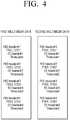
- FIG. 4is a view illustrating an example of a stream to which a time code and a time stamp are added according to an exemplary embodiment.
- the transmitting apparatus 100may transmit the first multimedia data and the second multimedia data in the form of a transport stream.
- the transmitting apparatus 100may generate a transport stream by packetizing a video Elementary Stream (ES), an audio ES, and an additional data ES constituting multimedia data using a Packetized Elementary Stream (PES) packetizer, and then multiplexing the video ES, the audio ES, and the additional data ES.
- PESPacketized Elementary Stream
- respective PES headersinclude PTS and DTS information
- ES headersinclude time code information.
- the time code informationmay be included in one of the video ES header, the audio ES header, and the additional data ES header.
- the first signal processor 240signal processes the first multimedia data received through the first receiver 210 and generates a video frame.
- the second signal processor 250signal processes the second multimedia data received through the second receiver 220 and generates a video frame.
- the first signal processor 240 and the second signal processor 250will be explained in detail with reference to FIG. 5 .
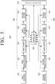
- FIG. 5is a block diagram to illustrate detailed configurations of the first and second signal processors according to an exemplary embodiment.
- the first signal processor 240includes a first demultiplexer 241, a first buffer 242, a first decoder 243, and a second buffer 244.
- the first demultiplexer 241receives the first multimedia data from the first receiver 210 and demultiplexes the first multimedia data. Specifically, the first demultiplexer 241 receives and demultiplexes the first multimedia data, thereby dividing the first multimedia data into first video data, first audio data, and first additional data.
- the first buffer 242stores the first video data which is demultiplexed from the first multimedia data. Specifically, the first buffer 242 may store the first video data which is demultiplexed from the first multimedia data in sequence.
- the first decoder 243decodes the first video data which is stored in the first buffer 242, and generates a first video frame. Specifically, the first decoder 242 performs a reverse process of the encoder (not shown) which encodes the first video data in the transmitting apparatus 100, and decodes the first video data when the DTS of the first video data is consistent with the system clock.
- the encoder (not shown) of the transmitting apparatus 100 which encodes the first video datamay perform MPEG-2 encoding with respect to the first video data for the sake of compatibility with an existing receiving apparatus which does not support data reception through a heterogenous network, and accordingly, the first decoder 242 of the receiving apparatus 200 may perform MPEG-2 decoding with respect to the first video data.
- the first video datais not limited to such a video format and may be encoded and decoded according to various video formats which are currently available such as H.264, HEVC, etc., and video formats which will be developed in the future and applicable to the present disclosure.
- the second buffer 244stores the first video frame which is generated by the first decoder 243. Specifically, the second buffer 244 may store the video frames which are generated in order of decoding the first video data by the first decoder 243 in sequence.
- the second signal processor 250includes a second demultiplexer 251, a third buffer 252, a second decoder 253, and a fourth buffer 254.
- the second demultiplexer 251receives the second multimedia data from the second receiver 220 and demultiplexes the second multimedia data. Specifically, the second demultiplexer 251 receives and demultiplexes the second multimedia data, thereby dividing the second multimedia data into second video data, second audio data, and second additional data.
- the third buffer 252stores the second video data which is demultiplexed from the second multimedia data. Specifically, the third buffer 252 may store the second video data which is demultiplexed from the second multimedia data in sequence.
- the second decoder 253decodes the second video data which is stored in the third buffer 252, and generates a second video frame. Specifically, the second decoder 252 performs a reverse process of the encoder (not shown) which encodes the second video data in the transmitting apparatus 100, and decodes the second video data when the DTS of the second video data is consistent with the system clock.
- the encoder (not shown) of the transmitting apparatus 100 which encodes the second video datamay perform H.264 encoding with respect to the second video data, and accordingly, the second decoder 252 of the receiving apparatus 200 may perform H.264 decoding with respect to the second video data.
- the second video datais not limited to such a video format and may be encoded and decoded according to various video formats which are currently available such as HEVC, etc., and video formats which will be developed in the future and applicable to the present disclosure.
- the fourth buffer 254stores the second video frame which is generated by the second decoder 253. Specifically, the fourth buffer 254 may store the video frames which are generated in order of decoding the second video data by the second decoder 253 in sequence.
- the first and second signal processors 240 and 250may further include a depacketizer to depacketize the demultiplexed video data, audio data, and additional data, and a buffer (not shown) and a decoder (not shown) to process the depacketized audio data and additional data.
- the decoded audio data and additional datamay be synchronized with the first video frame and the second video frame or rendered and may be output.
- this featurehas no direct relationship with the present disclosure and thus a detailed description thereof is omitted.
- the controller 260may control an overall operation of the receiving apparatus 260. Specifically, the controller 260 controls the first receiver 210, the second receiver 220, the first signal processor 240, the second signal processor 250, and the renderer 270 to receive and process the first multimedia data and the second multimedia data.
- the controller 260may detect information on the time code and the time stamp from the demultiplexed first multimedia data and second multimedia data. As described above with reference to FIG. 3 , the time code may be inserted into the ES header and the time stamp may be inserted into the PES header. Accordingly, the controller 260 may detect the time code and the time stamp after the first multimedia data and the second multimedia data have been demultiplexed. More specifically, the controller 260 may detect the time stamp from the PES header which is generated by demultiplexing the multimedia data, and may detect the time code from the ES header which is generated by depacketizing the PES using the depacketizer (not shown).
- the controller 260may detect the time code at any time after the multimedia data has been demultiplexed and depackterized. That is, the controller 260 may detect the time code from the video data which has been demultiplexed and stored in the buffer 242 or 252, or may detect the time code during the decoding process of the decoder 243 or 253. Also, the controller 260 may detect the time code from the data which has been decoded and stored in the buffer 244 or 254.
- the controller 260may compare a first time code of the first multimedia data and a second time code of the second multimedia data, and may calculate a difference in time stamp information of video frames that have matching time codes.
- a difference in the PTS of the two framesmay be 15.
- the same ruleis applied to the DTS.
- the controller 260may correct the DTS of one of the first and second video data stored in the first buffer 242 and the third buffer 252 using the difference in the time stamp information, so that the video data can be synchronized before being decoded by the decoders 243 and 253.
- controller 260may correct the DTS (or the PTS) of the first video data and the second video data (or the first and second video frames) using the difference in the time stamp information during the decoding process of the first decoder 243 and the second decoder 253, so that the video data can be synchronized.
- controller 260may correct the PTS of one of the first and second video frames stored in the second buffer 244 and the fourth buffer 254 using the difference in the time stamp information, so that the video frames can be synchronized before being input to the renderer 270.
- the renderer 270may perform rendering using the first video frame and the second video frame. Specifically, the renderer 270 renders the first video frame and the second video frame when the PTS of the first video frame and the second video frame is consistent with the system clock, and displays the first video frame and the second video frame on a display screen.
- the renderer 270may read out the video frame that is to be synchronized from among the first video frame stored in the second buffer 244 and the second video frame stored in the fourth buffer 254 using the difference in the time stamp information calculated by the controller 260, and may render the video frame.
- the time codeis inserted into the ES header of the transport stream and is transmitted to the receiving apparatus 200.
- the receiving apparatus 200may receive information on the time code through a separate stream and may synchronize the first video data and the second video data.
- the receiving apparatus 200may receive a map table including a packet order of the first multimedia data and the second multimedia data and the time code and the PTS information of the video frame included in each packet from an external apparatus such as a server through the first receiver 210 or the second receiver 220.
- the controller 260may compare the time code information of the first multimedia data and the second multimedia data, which is included in the received map table, and may compare the PTS of the first multimedia data and the second multimedia data having the matching time codes and calculate a difference in the PTS.
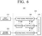
- FIG. 6is a block diagram illustrating a configuration of a receiving apparatus according to another exemplary embodiment.
- a receiving apparatus 200may further include a storage 280 in addition to a first receiver 210, a second receiver 220, a first signal processor 240, a second signal processor 250, a controller 260, and a renderer 270.
- the receiving apparatus 200When the receiving apparatus 200 receives first multimedia data and second multimedia data through different networks, there may be a difference in receiving time according to characteristics of the networks.
- the second multimedia datawhen the first multimedia data is transmitted through a broadcasting network and the second multimedia data is transmitted through an IP network, the second multimedia data may be late transmitted to the receiving apparatus due to the characteristics of the IP network.
- the first multimedia data and the second multimedia dataare received at similar time, the first multimedia data and the second multimedia data may be in condition in which they can be synchronized with each other by correcting the time stamp as described above.
- a difference in the receiving time between the first multimedia data and the second multimedia datais great, it may be impossible to synchronize simply by correcting the PTS. That is, when one of the first multimedia data and the second multimedia data is late received, video frames having the same time code cannot be found and thus it may be impossible to synchronize the respective video frames.
- the receiving apparatus 200may include the storage 280 to store the first multimedia data or the second multimedia data to delay the multimedia data that is received first from among the first multimedia data and the second multimedia data.
- the storage 280may be implemented by using a Personal Video Recorder (PVR).
- PVRPersonal Video Recorder
- a case in which the first multimedia data is received through a broadcasting network and the second multimedia data is received through an IP networkwill be explained by way of an example.
- the storage 280may store the first multimedia data received through the first receiver 210.
- the controller 260may control the first signal processor 240 to process the first multimedia data.
- the controller 260may compare a first time code added to the first multimedia data stored in the storage 280 and a second time code added to the second multimedia data received through the second receiver 220, thereby determining whether the second multimedia data to be synchronized with the multimedia data stored in the storage 280 is received or not.
- the controller 260detects a time code from the first multimedia data stored in the storage 280.
- the time codemay be inserted into the ES header, and the controller 260 should demultiplex the first multimedia data stored in the storage 280 to detect the time code from the first multimedia data (More specifically, the time code may be detected after the PES data which is generated by demultiplexing the first multimedia data is depacketized).
- the first signal processormay demultiplex the first multimedia data using the first demultiplexer 241.
- the first signal processor 240may include a separate demultiplexer to demultiplex the first multimedia data stored in the storage 280.
- the controller 260may detect a time code from the second multimedia data.
- the controller 260may compare the time code detected from the second multimedia data and the time code detected from the first multimedia data stored in the storage 280, and, when there are matching time codes, may determine that the second multimedia data to be synchronized with the first multimedia data stored in the storage 280 is received.
- the controller 260may control the respective elements of the receiving apparatus 200 to synchronize and reproduce the first multimedia data and the second multimedia data. This has been described above with reference to FIG. 5 and a detailed description is omitted.
- the receiving apparatus 200may perform a different operation according to a condition in which the first multimedia data is stored in the storage 280. This will be explained in detail with reference to FIGS. 7 and 8 .
- FIG. 7is a view to illustrate a method for delaying first multimedia data and processing the first multimedia data according to an exemplary embodiment. Specifically, FIG. 7 illustrates a method in which, when the receiving apparatus 200 receives a user command to synchronize and reproduce first multimedia data and second multimedia data while processing and reproducing only the first multimedia data, the receiving apparatus 200 stores the first multimedia data received from the time when the user command is input.
- the first multimedia data received after the user command is input(after the fourth packet of the first multimedia data 710 of FIG. 7 ) is stored in the storage 280.
- the receiving apparatus 200may request the second multimedia data from the transmitting apparatus 100 or a server which provides the second multimedia data, and may receive the second multimedia data 720 through the IP network.
- a predetermined timeis required until the receiving apparatus 200 requests the second multimedia data and receives a first packet, and additionally, a predetermined time may be required from a time (t1) when the first packet of the second multimedia data is received to a time (t2) when a fourth packet of the second multimedia data to be synchronized with the first multimedia data stored in the storage 280 and reproduced is received.
- the receiving apparatus 200may stop reproducing the first multimedia data from the time (t0) when the user command is input to the time (t2) when the fourth packet of the second multimedia data is received, and may synchronize and reproduce the second multimedia data and the first multimedia data when the fourth packet of the second multimedia data is received.
- the receiving apparatus 200may reproduce only the first multimedia data, and, when the fourth packet of the second multimedia data is received (t2), the receiving apparatus 200 may synchronize the fourth packet of the second multimedia data and the first multimedia data again and reproduce the second multimedia data and the first multimedia data.
- the receiving apparatus 200delays processing the first multimedia data stored in the storage 280 and synchronizes and reproduces the first multimedia data and the second multimedia data.
- FIG. 8is a view to illustrate a method for delaying and processing first multimedia data according to another exemplary embodiment. Specifically, FIG. 8 is a view to illustrate a case in which the receiving apparatus 200 stores first multimedia data in the storage 280 from the time when the first multimedia data 810 is initially reproduced (that is, a case in which the first multimedia data is stored from its first packet).
- the receiving apparatus 200receives the first multimedia data 810 through the RF network and reproduces the first multimedia data 810, and stores the first multimedia data in the storage 280 from the first packet. After that, when a user command to synchronize and reproduce the first multimedia data and the second multimedia data is input, the receiving apparatus 200 requests the second multimedia data 820 from the transmitting apparatus 100 or the server and receives the second multimedia data 820 through the IP network.
- the receiving apparatus 200finds a packet of the first multimedia data that is to be synchronized with the first packet of the second multimedia data and reproduced from among the packets of the first multimedia data stored in the storage 280 (that is, the first packet of the first multimedia data), synchronizes the packet of the first multimedia data and the first packet of the second multimedia data, and outputs the packets. That is, the receiving apparatus 200 may synchronize the first multimedia data and the second multimedia data and may reproduce the multimedia content from the beginning.
- the receiving apparatus 200delays processing the first multimedia data stored in the storage 280 and synchronizes and reproduces the first multimedia data and the second multimedia data.
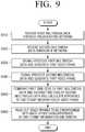
- FIG. 9is a flowchart to illustrate a receiving method of a receiving apparatus according to an exemplary embodiment.
- first multimedia datais received through a broadcasting network (S910) and second multimedia data is received through an IP network (S920).
- the first multimedia datais signal processed and a first video frame is generated (S930).
- the generating the first video framemay include demultiplexing the first multimedia data, storing first video data demultiplexed from the first multimedia data in a first buffer, decoding the first video data and generating a first video frame, and storing the first video frame in a second buffer.
- the second multimedia datais signal processed and a second video frame is generated (S940).
- the generating the second video framemay include demultiplexing the second multimedia data, storing second video data demultiplexed from the second multimedia data in a third buffer, decoding the second video data and generating a second video frame, and storing the second video frame in a fourth buffer.
- a first time code of the first multimedia data and a second time code of the second multimedia dataare compared with each other and a difference in time stamp information of video frames having matching time codes is calculated (S950).
- video frames to be synchronizedare read out from among the first video frame and the second video frame using the difference in the time stamp information and rendering is performed (S960).
- the receiving method of the receiving apparatusmay further include correcting time stamp information of one of the first video data and the second video data stored in the first buffer and the third buffer using the difference in the time stamp information.
- the receiving methodmay further include storing the first multimedia data received through a first receiver.
- the generating the first video framemay include signal processing the first multimedia data when the second multimedia data to be synchronized with the first multimedia data is received.
- the generating the first video framemay include comparing a first time code added to the stored first multimedia data and a second time code added to the received second multimedia data, and determining whether the second multimedia data to be synchronized with the stored first multimedia data is received or not.
- the storingmay include, when a user command to synchronize and reproduce the first multimedia data and the second multimedia data is input, storing the first multimedia data.
- a program to perform the method according to the above-described various exemplary embodimentsmay be stored on various kinds of recording media and used.
- a code to perform the above-described methodsmay be stored in various kinds of non-volatile recording media such as a flash memory, a Read Only Memory (ROM), an Erasable Programmable ROM (EPROM), an Electronically Erasable and Programmable ROM (EEPROM), a hard disk, a removable disk, a memory card, a USB memory, and a CD-ROM.
- non-volatile recording mediasuch as a flash memory, a Read Only Memory (ROM), an Erasable Programmable ROM (EPROM), an Electronically Erasable and Programmable ROM (EEPROM), a hard disk, a removable disk, a memory card, a USB memory, and a CD-ROM.
Landscapes
- Engineering & Computer Science (AREA)
- Signal Processing (AREA)
- Multimedia (AREA)
- Databases & Information Systems (AREA)
- Two-Way Televisions, Distribution Of Moving Picture Or The Like (AREA)
- Testing, Inspecting, Measuring Of Stereoscopic Televisions And Televisions (AREA)
Description
- Methods and apparatuses consistent with exemplary embodiments relate to a receiving apparatus and a receiving method thereof, and more particularly, to a receiving apparatus which receives and processes a plurality of streams, and a receiving method thereof.
- With the development of electronic technologies, various kinds of electronic apparatuses have been developed and distributed. In particular, televisions (TVs) are able to provide 3D contents or contents of higher resolution, and accordingly, development of technologies for providing a content including a plurality of images like a 3D content, a multi- angle content, and a content having depth images or a content of ultra high definition (UHD) level image quality is ongoing.
- A channel bandwidth used in an existing broadcasting network is limited, whereas a multi-angle content, a 3D content, or a content of UHD level image quality has a data size greater than that of the existing content. Therefore, the existing broadcasting network has difficulty in transmitting the content of the great data size as it is.
- Investing in new equipments to provide new contents may incur much cost. Existing broadcasting equipments and receiving apparatuses should be used to provide new contents. Accordingly, a method of transmitting reference multimedia data from among a plurality of multimedia data included in a multimedia content through an existing broadcasting network and transmitting additional multimedia data through a transmission path which his different from the existing broadcasting network may be considered.
- However, when data is transmitted through different transmission networks, respective multimedia data use independent encoders. System clocks of the respective encoders do not match each other and thus it is difficult to add the same synchronization information.
WO 2009/020302-A discloses a system in which in order to achieve synchronization of ensemble transport interface (ETI) signals of a first network and a second network, a synchronization device receives a first ETI signal from the first network and a second ETI signal from the second network, generates delay times between the same frames, compares frames of the first ETI signal and frames of the second ETI signal, and then synchronizes the first ETI signal and the second ETI signal according to the delay time.JP2004254149-A US 2008/0037954 A1 describes a process to detect video glitches and audio-video synchronization errors arising during playback or capture. The process encodes an external time stamp into video and audio streams directly at the output of a digital media playback device. The process captures the stamped video and audio streams and analyzes the external stamp by comparing it with a presentation time stamp and a capture time stamp.US 2010/142624 A1 describes a decoder. A video decoder extracts, when receiving a video stream, video output time information attached to each video frame. Thereafter, a difference value calculator calculates a difference value between an occurrence time of a synchronizing signal and the video output time information. Further, an audio output time corrector corrects, using the difference value, audio output time information attached to each audio frame. Then, a video source outputs video represented by a video frame in synchronization with a synchronizing signal. An audio source outputs, when a value of reference time information and a corrected value of the audio output time information are synchronized, audio represented by an audio frame with the synchronized audio output time information.- One or more exemplary embodiments provide a receiving apparatus which receives a plurality of streams through different paths and processes the streams, and a receiving method thereof. One or more exemplary embodiments also provide a method for synchronizing a plurality of streams provided through different paths and reproducing the plurality of streams.
- The invention provides a receiving apparatus and method thereof as set out in the claims of this specification. According to an aspect of an exemplary embodiment, there is provided a receiving apparatus including: a first receiver configured to receive first multimedia data to which a first time code is added in every frame through a broadcasting network; a second receiver configured to receive second multimedia data to which a second time code is added in every frame through an IP network; a first signal processor configured to signal process the first multimedia data and generate a first video frame; a second signal processor configured to signal process the second multimedia data and generate a second video frame; a controller configured to compare the first time code of the first multimedia data and the second time code of the second multimedia data and calculate a difference in time stamp information of video frames having matching time codes; and a renderer configured to read out video frames to be synchronized with each other from among the first video frame and the second video frame using the difference in the time stamp information, and render the video frames.
- The first signal processor may include: a first demultiplexer configured to demultiplex the received first multimedia data; a first buffer configured to store first video data which is demultiplexed from the first multimedia data; a first decoder configured to decode the first video data stored in the first buffer and generate the first video frame; and a second buffer configured to store the generated first video frame, and the second signal processor may include: a second demultiplexer configured to demultiplex the received second multimedia data; a third buffer configured to store second video data which is demultiplexed from the second multimedia data; a second decoder configured to decode the second video data stored in the third buffer and generate the second video frame; and a fourth buffer configured to store the generated second video frame.
- The controller may correct time stamp information of one of the first video data and the second video data stored in the first buffer and the third buffer using the difference in the time stamp information.
- The receiving apparatus may further include a storage configured to store the first multimedia data received through the first receiver, and, when the second multimedia data to be synchronized with the stored first multimedia data is received, the controller may control the first signal processor to process the stored first multimedia data.
- The controller may compare the first time code added to the first multimedia data stored in the storage and the second time code added to the second multimedia data received through the second receiver, and may determine whether the second multimedia data to be synchronized with the stored first multimedia data is received or not.
- When a user command to synchronize and reproduce the first multimedia data and the second multimedia data is input, the controller may control the storage to store the first multimedia data.
- According to an aspect of another exemplary embodiment, there is provided a method for receiving of a receiving apparatus, the method including: receiving first multimedia data to which a first time code is added in every frame through a broadcasting network; receiving second multimedia data to which a second time code is added in every frame through an IP network; signal processing the first multimedia data and generating a first video frame; signal processing the second multimedia data and generating a second video frame; comparing the first time code of the first multimedia data and the second time code of the second multimedia data and calculating a difference in time stamp information of video frames having matching time codes; and reading out video frames to be synchronized with each other from among the first video frame and the second video frame using the difference in the time stamp information, and rendering the video frames.
- The generating the first video frame may include: demultiplexing the received first multimedia data; storing first video data which is demultiplexed from the first multimedia data in a first buffer; decoding the first video data stored in the first buffer and generating the first video frame; and storing the generated first video frame in a second buffer, and the generating the second video frame may include: demultiplexing the received second multimedia data; storing second video data which is demultiplexed from the second multimedia data in a third buffer; decoding the second video data stored in the third buffer and generating the second video frame; and storing the generated second video frame in a fourth buffer.
- The method may further include correcting time stamp information of one of the first video data and the second video data stored in the first buffer and the third buffer using the difference in the time stamp information.
- The method may further include storing the first multimedia data received through a first receiver, and the generating the first video frame may include, when the second multimedia data to be synchronized with the stored first multimedia data is received, signal processing the stored first multimedia data.
- The generating the first video frame may include comparing the first time code added to the stored first multimedia data and the second time code added to the received second multimedia data, and determining whether the second multimedia data to be synchronized with the stored first multimedia data is received or not.
- The storing may include, when a user command to synchronize and reproduce the first multimedia data and the second multimedia data is input, storing the first multimedia data.
- According to the above-described various exemplary embodiments, different data are received and transmitted through different paths using existing broadcasting equipments and the limitation of the transmission bandwidth is overcome, so that new contents can be provided to the user.
- Also, even when a plurality of streams are provided through different paths, multimedia data can be effectively synchronized and reproduced.
- The above and/or other aspects of the invention will become and more readily appreciated from the following description of the exemplary embodiments, taken in conjunction with the accompanying drawings of which:
FIG. 1 is a view illustrating a multimedia data exchanging system according to an exemplary embodiment;FIG. 2 is a block diagram illustrating a configuration of a multimedia data exchanging system according to an exemplary embodiment;FIG. 3 is a block diagram illustrating a detailed configuration of a receiving apparatus according to an exemplary embodiment;FIG. 4 is a view illustrating an example of a stream to which a time code and a time stamp are added according to an exemplary embodiment;FIG. 5 is a block diagram to illustrate detailed configurations of first and second signal processors according to an exemplary embodiment;FIG. 6 is a block diagram illustrating a configuration of a receiving apparatus according to another exemplary embodiment;FIG. 7 is a view to illustrate a method for delaying and processing first multimedia data according to an exemplary embodiment;FIG. 8 is a view to illustrate a method for delaying and processing first multimedia data according to another exemplary embodiment; andFIG. 9 is a flowchart to illustrate a receiving method of a receiving apparatus according to an exemplary embodiment.- Reference will now be made in detail to the present exemplary embodiments of the present invention, examples of which are illustrated in the accompanying drawings, wherein like reference numerals refer to the like elements throughout. The exemplary embodiments are described below in order to explain the present invention by referring to the figures.
FIG. 1 is a view illustrating a multimedia data exchanging system according to an exemplary embodiment. Referring toFIG. 1 , a multimediadata exchanging system 1000 includes a transmittingapparatus 100 and a receivingapparatus 200.- The transmitting
apparatus 100 processes multimedia data and transmits different signals through different transmission networks. For example, the transmittingapparatus 100 may transmit a first signal through a first transmission network and may transmit a second signal through a second transmission network. - The first signal and the second signal may be different multimedia data constituting a single content, or may be multimedia data of relatively low image quality and multimedia data of relatively high image quality. For example, when the multimedia data is a 3D content, one of a left-eye image and a right-eye image may be transmitted through the first transmission network and the other one may be transmitted through the second transmission network. For another example, a first signal of full high definition (FHD) image quality may be transmitted through the first transmission network, and a second signal of ultra high definition (UHD) image quality may be transmitted through the second transmission network. In addition, the first signal and the second signal may be multimedia data constituting a multi-angle content, a 2D image or, a depth image.
- Herein, the first transmission network may be a radio frequency (RF) network (or a broadcasting network) and the second transmission network may be an internet protocol (IP) network (or Internet). However, this is merely an example. The first transmission network may be the IP network and the second transmission network may be the RF network or the first transmission network and the second transmission network may be the same type of network.
- The receiving
apparatus 200 may receive the first signal and the second signal from the transmittingapparatus 100, perform signal processing with respect to the multimedia data, synchronize the multimedia data, and reproduce the content. - The receiving
apparatus 200 may receive the second signal from a server. That is, the receivingapparatus 200 may receive the second signal directly from the transmittingapparatus 100 or may receive the second signal generated in the transmittingapparatus 100 through a separate server. - The signal transmitted through the first transmission network and the second transmission network may include a Program Clock Reference (PCR), a Decoding Time Stamp (DTS), and a Presentation Time Stamp (PTS) for synchronizing.
- The PCR refers to reference time information based on which the receiving apparatus (set-top box or TV) sets a time reference according to that of the transmitting apparatus. The receiving apparatus sets a System Time Clock (STC) value according to the PCR. The DTS is a time stamp for informing a decoding time of data, and the PTS refers to a time stamp for informing a reproducing time for synchronizing a video and a voice. The DTS and the PTS are referred to as a time stamp in the present specification.
- When different signals are transmitted from different transmitting apparatuses 100-1 and 100-2, the PCR may be different according to characteristics of the transmitting apparatuses 100-1 and 100-2. Specifically, this is because that different signals use different encoders, and the respective encoders may not have consistent system operation clock information and may have different operation way and delay. Therefore, although the receiving apparatus reproduces the content according to the time stamp matching the PCR, synchronization may not be performed.
- The receiving
apparatus 200 of the system according to the exemplary embodiment may correct the time stamp using a time code and may perform synchronization. FIG. 2 is a block diagram illustrating a configuration of a multimedia data exchanging system according to an exemplary embodiment. Referring toFIG. 2 , a transmittingapparatus 100 of a multimediadata exchanging system 1000 includes adata generator 110, afirst transmitter 120, and asecond transmitter 130.- The
data processor 110 processes multimedia data and transmits the multimedia data to thefirst transmitter 120 and thesecond transmitter 130. Specifically, thedata processor 110 processes first multimedia data and second multimedia data constituting a multimedia content and transmits the first multimedia data and the second multimedia data to thefirst transmitter 120 and thesecond transmitter 130, respectively. The first multimedia data and the second multimedia data may include synchronization information for synchronizing. - The
first transmitter 120 transmits the first multimedia data to a receivingapparatus 200 through a first transmission network. To achieve this, thefirst transmitter 120 may convert the first multimedia data into a form suitable for a transmission standard of the first transmission network and may transmit the first multimedia data to the receivingapparatus 200. - The
second transmitter 130 transmits the second multimedia data to the receivingapparatus 200 through a second transmission network. To achieve this, thesecond transmitter 130 may convert the second multimedia data to a form suitable for a transmission standard of the second transmission network. - The receiving
apparatus 200 of the multimedia data exchanging system includes afirst receiver 210, asecond receiver 220, and adata processor 230. - The
first receiver 210 receives the first multimedia data from the transmittingapparatus 100 through the first transmission network. Thesecond receiver 220 receives the second multimedia data from the transmittingapparatus 100 through the second transmission network. For example, thefirst receiver 210 may receive the first multimedia data through a broadcasting network and thesecond receiver 220 may receive the second multimedia data through an IP network. - The
data processor 230 processes the first transmission data and the second transmission data and forms a multimedia content. Specifically, thedata processor 230 signal processes the first multimedia data and the second multimedia data and generates video frames, and synchronizes the video frame of the first multimedia data and the video frame of the second multimedia data using synchronization information included in the first multimedia data and the second multimedia data, and renders the video frames. FIG. 3 is a block diagram illustrating a detailed configuration of a receiving apparatus according to an exemplary embodiment. Referring toFIG. 3 , a receivingapparatus 200 includes afirst receiver 210, asecond receiver 220, afirst signal processor 240, asecond signal processor 250, acontroller 260, and arenderer 270.- The
first receiver 210 receives first multimedia data. Specifically, thefirst receiver 210 may receive first multimedia data to which a first time code is added in every frame through a broadcasting network. - The
second receiver 220 receives second multimedia data. Specifically, thesecond receiver 220 may receive second multimedia data to which a second time code is added in every frame through the broadcasting network. - The configurations of the
first receiver 210 and thesecond receiver 220 may be implemented variously according to their communication paths. For example, when thefirst receiver 210 and thesecond receiver 220 are modules to receive signals transmitted through a broadcasting network, thefirst receiver 210 and thesecond receiver 220 may include elements likes an antenna, a tuner, a demodulator, an equalizer, etc. When thefirst receiver 210 and thesecond receivers 220 are modules to receive signals through a network, thefirst receiver 210 and thesecond receiver 220 may include a network communication module. - The time code added to the respective multimedia data may be a Society of Motion Picture and Television Engineers (SMPTE) time code. SMPTE 12M represents a time code in the form of "clock:minute:second:frame". The SMPTE 12M time code may be inserted when raw data such as a movie, a video, a sound, etc. is obtained and edited, and may serve as a reference to correct and edit on a time axis. Theraw data obtained on the same time axis may have the same time code value.
- The SMPTE time code may be divided into a Longitude Time Code (LTC) and a Vertical Interval Time Code (VITC) according to a recording method. The LTC is recorded according to an advancing direction of a tape. The LTC may consist of data of 80 bits in total, including visual information (25 bits), user information (32 bits), synchronization information (16 bits), reserved area (4 bits), and frame mode display (2 bits). The VITC is recorded on two horizontal lines within a vertical blanking interval of a video signal.
- SMPTE RP-188 defines an interface standard for transmitting a time code of an LTC or VITC type as ancillary data, and the time code may be transmitted according to such an interface standard.
- The first and second multimedia data may include a time stamp for synchronizing in addition to the time code. Specifically, the first and second multimedia data each includes a DTS and a PTS. It is common that the time stamp is used as synchronization information for synchronizing. However, in heterogenous network-based multimedia data exchanging system, the first multimedia data and the second multimedia data are encoded by different encoders and thus there is a problem that system clocks may not be consistent with each other. Accordingly, the above-described time code may be used for synchronizing. A detailed description thereof will be provided below.
FIG. 4 is a view illustrating an example of a stream to which a time code and a time stamp are added according to an exemplary embodiment. The transmittingapparatus 100 may transmit the first multimedia data and the second multimedia data in the form of a transport stream.- Specifically, the transmitting
apparatus 100 may generate a transport stream by packetizing a video Elementary Stream (ES), an audio ES, and an additional data ES constituting multimedia data using a Packetized Elementary Stream (PES) packetizer, and then multiplexing the video ES, the audio ES, and the additional data ES. As shown inFIG. 4 , respective PES headers include PTS and DTS information, and ES headers include time code information. In particular, the time code information may be included in one of the video ES header, the audio ES header, and the additional data ES header. - The
first signal processor 240 signal processes the first multimedia data received through thefirst receiver 210 and generates a video frame. Thesecond signal processor 250 signal processes the second multimedia data received through thesecond receiver 220 and generates a video frame. Thefirst signal processor 240 and thesecond signal processor 250 will be explained in detail with reference toFIG. 5 . FIG. 5 is a block diagram to illustrate detailed configurations of the first and second signal processors according to an exemplary embodiment. Referring toFIG. 5 , thefirst signal processor 240 includes afirst demultiplexer 241, afirst buffer 242, afirst decoder 243, and asecond buffer 244.- The
first demultiplexer 241 receives the first multimedia data from thefirst receiver 210 and demultiplexes the first multimedia data. Specifically, thefirst demultiplexer 241 receives and demultiplexes the first multimedia data, thereby dividing the first multimedia data into first video data, first audio data, and first additional data. - The
first buffer 242 stores the first video data which is demultiplexed from the first multimedia data. Specifically, thefirst buffer 242 may store the first video data which is demultiplexed from the first multimedia data in sequence. - The
first decoder 243 decodes the first video data which is stored in thefirst buffer 242, and generates a first video frame. Specifically, thefirst decoder 242 performs a reverse process of the encoder (not shown) which encodes the first video data in the transmittingapparatus 100, and decodes the first video data when the DTS of the first video data is consistent with the system clock. In particular, the encoder (not shown) of the transmittingapparatus 100 which encodes the first video data may perform MPEG-2 encoding with respect to the first video data for the sake of compatibility with an existing receiving apparatus which does not support data reception through a heterogenous network, and accordingly, thefirst decoder 242 of the receivingapparatus 200 may perform MPEG-2 decoding with respect to the first video data. However, the first video data is not limited to such a video format and may be encoded and decoded according to various video formats which are currently available such as H.264, HEVC, etc., and video formats which will be developed in the future and applicable to the present disclosure. - The
second buffer 244 stores the first video frame which is generated by thefirst decoder 243. Specifically, thesecond buffer 244 may store the video frames which are generated in order of decoding the first video data by thefirst decoder 243 in sequence. - Referring to
FIG. 5 , thesecond signal processor 250 includes asecond demultiplexer 251, athird buffer 252, asecond decoder 253, and afourth buffer 254. - The
second demultiplexer 251 receives the second multimedia data from thesecond receiver 220 and demultiplexes the second multimedia data. Specifically, thesecond demultiplexer 251 receives and demultiplexes the second multimedia data, thereby dividing the second multimedia data into second video data, second audio data, and second additional data. - The
third buffer 252 stores the second video data which is demultiplexed from the second multimedia data. Specifically, thethird buffer 252 may store the second video data which is demultiplexed from the second multimedia data in sequence. - The
second decoder 253 decodes the second video data which is stored in thethird buffer 252, and generates a second video frame. Specifically, thesecond decoder 252 performs a reverse process of the encoder (not shown) which encodes the second video data in the transmittingapparatus 100, and decodes the second video data when the DTS of the second video data is consistent with the system clock. In particular, the encoder (not shown) of the transmittingapparatus 100 which encodes the second video data may perform H.264 encoding with respect to the second video data, and accordingly, thesecond decoder 252 of the receivingapparatus 200 may perform H.264 decoding with respect to the second video data. However, the second video data is not limited to such a video format and may be encoded and decoded according to various video formats which are currently available such as HEVC, etc., and video formats which will be developed in the future and applicable to the present disclosure. - The
fourth buffer 254 stores the second video frame which is generated by thesecond decoder 253. Specifically, thefourth buffer 254 may store the video frames which are generated in order of decoding the second video data by thesecond decoder 253 in sequence. - The first and
second signal processors - The
controller 260 may control an overall operation of the receivingapparatus 260. Specifically, thecontroller 260 controls thefirst receiver 210, thesecond receiver 220, thefirst signal processor 240, thesecond signal processor 250, and therenderer 270 to receive and process the first multimedia data and the second multimedia data. - The
controller 260 may detect information on the time code and the time stamp from the demultiplexed first multimedia data and second multimedia data. As described above with reference toFIG. 3 , the time code may be inserted into the ES header and the time stamp may be inserted into the PES header. Accordingly, thecontroller 260 may detect the time code and the time stamp after the first multimedia data and the second multimedia data have been demultiplexed. More specifically, thecontroller 260 may detect the time stamp from the PES header which is generated by demultiplexing the multimedia data, and may detect the time code from the ES header which is generated by depacketizing the PES using the depacketizer (not shown). - Also, the
controller 260 may detect the time code at any time after the multimedia data has been demultiplexed and depackterized. That is, thecontroller 260 may detect the time code from the video data which has been demultiplexed and stored in thebuffer decoder controller 260 may detect the time code from the data which has been decoded and stored in thebuffer - The
controller 260 may compare a first time code of the first multimedia data and a second time code of the second multimedia data, and may calculate a difference in time stamp information of video frames that have matching time codes. - For example, when the first video frame and the second video frame have the same time code, and a PTS of the first video frame (PTS_1) is 115 and a PTS of the second video frame (PTS_2) is 100, a difference in the PTS of the two frames may be 15. The same rule is applied to the DTS.
- The
controller 260 calculates the difference in the time stamp information and corrects the time stamp, so that the first video data (or the first video frame) and the second video data (or the second video frame) can be synchronized with each other. For example, when PTS_1-PTS_2=15, the PTS may be corrected so that the first video frame is output 15 frames later than the second video frame which has the same time code as that of the first video frame. - The
controller 260 may correct the DTS of one of the first and second video data stored in thefirst buffer 242 and thethird buffer 252 using the difference in the time stamp information, so that the video data can be synchronized before being decoded by thedecoders - In addition, the
controller 260 may correct the DTS (or the PTS) of the first video data and the second video data (or the first and second video frames) using the difference in the time stamp information during the decoding process of thefirst decoder 243 and thesecond decoder 253, so that the video data can be synchronized. - In addition, the
controller 260 may correct the PTS of one of the first and second video frames stored in thesecond buffer 244 and thefourth buffer 254 using the difference in the time stamp information, so that the video frames can be synchronized before being input to therenderer 270. - The
renderer 270 may perform rendering using the first video frame and the second video frame. Specifically, therenderer 270 renders the first video frame and the second video frame when the PTS of the first video frame and the second video frame is consistent with the system clock, and displays the first video frame and the second video frame on a display screen. - The
renderer 270 may read out the video frame that is to be synchronized from among the first video frame stored in thesecond buffer 244 and the second video frame stored in thefourth buffer 254 using the difference in the time stamp information calculated by thecontroller 260, and may render the video frame. - In the above-described exemplary embodiment, the time code is inserted into the ES header of the transport stream and is transmitted to the receiving
apparatus 200. However, the receivingapparatus 200 may receive information on the time code through a separate stream and may synchronize the first video data and the second video data. Specifically, the receivingapparatus 200 may receive a map table including a packet order of the first multimedia data and the second multimedia data and the time code and the PTS information of the video frame included in each packet from an external apparatus such as a server through thefirst receiver 210 or thesecond receiver 220. Thecontroller 260 may compare the time code information of the first multimedia data and the second multimedia data, which is included in the received map table, and may compare the PTS of the first multimedia data and the second multimedia data having the matching time codes and calculate a difference in the PTS. FIG. 6 is a block diagram illustrating a configuration of a receiving apparatus according to another exemplary embodiment. Referring toFIG. 6 , a receivingapparatus 200 may further include astorage 280 in addition to afirst receiver 210, asecond receiver 220, afirst signal processor 240, asecond signal processor 250, acontroller 260, and arenderer 270.- When the receiving
apparatus 200 receives first multimedia data and second multimedia data through different networks, there may be a difference in receiving time according to characteristics of the networks. In particular, when the first multimedia data is transmitted through a broadcasting network and the second multimedia data is transmitted through an IP network, the second multimedia data may be late transmitted to the receiving apparatus due to the characteristics of the IP network. When the first multimedia data and the second multimedia data are received at similar time, the first multimedia data and the second multimedia data may be in condition in which they can be synchronized with each other by correcting the time stamp as described above. However, when a difference in the receiving time between the first multimedia data and the second multimedia data is great, it may be impossible to synchronize simply by correcting the PTS. That is, when one of the first multimedia data and the second multimedia data is late received, video frames having the same time code cannot be found and thus it may be impossible to synchronize the respective video frames. - Accordingly, the receiving
apparatus 200 may include thestorage 280 to store the first multimedia data or the second multimedia data to delay the multimedia data that is received first from among the first multimedia data and the second multimedia data. Thestorage 280 may be implemented by using a Personal Video Recorder (PVR). Hereinafter, a case in which the first multimedia data is received through a broadcasting network and the second multimedia data is received through an IP network will be explained by way of an example. - When the first multimedia data is received through the broadcasting network and the second multimedia data is received through the IP network, the
storage 280 may store the first multimedia data received through thefirst receiver 210. - When the second multimedia data to be synchronized with the multimedia data stored in the
storage 280 is received, thecontroller 260 may control thefirst signal processor 240 to process the first multimedia data. Thecontroller 260 may compare a first time code added to the first multimedia data stored in thestorage 280 and a second time code added to the second multimedia data received through thesecond receiver 220, thereby determining whether the second multimedia data to be synchronized with the multimedia data stored in thestorage 280 is received or not. - Specifically, the
controller 260 detects a time code from the first multimedia data stored in thestorage 280. As explained inFIG. 3 , the time code may be inserted into the ES header, and thecontroller 260 should demultiplex the first multimedia data stored in thestorage 280 to detect the time code from the first multimedia data (More specifically, the time code may be detected after the PES data which is generated by demultiplexing the first multimedia data is depacketized). To achieve this, the first signal processor may demultiplex the first multimedia data using thefirst demultiplexer 241. Also, thefirst signal processor 240 may include a separate demultiplexer to demultiplex the first multimedia data stored in thestorage 280. - Also, when the second multimedia data is received through the
second receiver 220, thecontroller 260 may detect a time code from the second multimedia data. Thecontroller 260 may compare the time code detected from the second multimedia data and the time code detected from the first multimedia data stored in thestorage 280, and, when there are matching time codes, may determine that the second multimedia data to be synchronized with the first multimedia data stored in thestorage 280 is received. - When the
controller 260 determines that the second multimedia data to be synchronized with the first multimedia data is received, thecontroller 260 may control the respective elements of the receivingapparatus 200 to synchronize and reproduce the first multimedia data and the second multimedia data. This has been described above with reference toFIG. 5 and a detailed description is omitted. - The receiving
apparatus 200 may perform a different operation according to a condition in which the first multimedia data is stored in thestorage 280. This will be explained in detail with reference toFIGS. 7 and8 . FIG. 7 is a view to illustrate a method for delaying first multimedia data and processing the first multimedia data according to an exemplary embodiment. Specifically,FIG. 7 illustrates a method in which, when the receivingapparatus 200 receives a user command to synchronize and reproduce first multimedia data and second multimedia data while processing and reproducing only the first multimedia data, the receivingapparatus 200 stores the first multimedia data received from the time when the user command is input.- When a user command to synchronize and reproduce the first multimedia data and the second multimedia data is input while the
first multimedia data 710 is received through the RF network and reproduced (for example, when a user command to reproduce a 3D content is input while a 2D content is reproduced, the first multimedia data received after the user command is input (after the fourth packet of thefirst multimedia data 710 ofFIG. 7 ) is stored in thestorage 280. - When the user command is input, the receiving
apparatus 200 may request the second multimedia data from the transmittingapparatus 100 or a server which provides the second multimedia data, and may receive thesecond multimedia data 720 through the IP network. In this case, there is a delay between a time when the user command is input and a time when the first multimedia data and the second multimedia data are synchronized and reproduced. For example, a predetermined time is required until the receivingapparatus 200 requests the second multimedia data and receives a first packet, and additionally, a predetermined time may be required from a time (t1) when the first packet of the second multimedia data is received to a time (t2) when a fourth packet of the second multimedia data to be synchronized with the first multimedia data stored in thestorage 280 and reproduced is received. - Accordingly, the receiving
apparatus 200 may stop reproducing the first multimedia data from the time (t0) when the user command is input to the time (t2) when the fourth packet of the second multimedia data is received, and may synchronize and reproduce the second multimedia data and the first multimedia data when the fourth packet of the second multimedia data is received. - Also, even when the user command is input, the receiving
apparatus 200 may reproduce only the first multimedia data, and, when the fourth packet of the second multimedia data is received (t2), the receivingapparatus 200 may synchronize the fourth packet of the second multimedia data and the first multimedia data again and reproduce the second multimedia data and the first multimedia data. - As a result, even when reception of the second multimedia data through the IP stream is delayed, the receiving
apparatus 200 delays processing the first multimedia data stored in thestorage 280 and synchronizes and reproduces the first multimedia data and the second multimedia data. FIG. 8 is a view to illustrate a method for delaying and processing first multimedia data according to another exemplary embodiment. Specifically,FIG. 8 is a view to illustrate a case in which the receivingapparatus 200 stores first multimedia data in thestorage 280 from the time when thefirst multimedia data 810 is initially reproduced (that is, a case in which the first multimedia data is stored from its first packet).- The receiving
apparatus 200 receives thefirst multimedia data 810 through the RF network and reproduces thefirst multimedia data 810, and stores the first multimedia data in thestorage 280 from the first packet. After that, when a user command to synchronize and reproduce the first multimedia data and the second multimedia data is input, the receivingapparatus 200 requests thesecond multimedia data 820 from the transmittingapparatus 100 or the server and receives thesecond multimedia data 820 through the IP network. When the first packet of the second multimedia data is received, the receivingapparatus 200 finds a packet of the first multimedia data that is to be synchronized with the first packet of the second multimedia data and reproduced from among the packets of the first multimedia data stored in the storage 280 (that is, the first packet of the first multimedia data), synchronizes the packet of the first multimedia data and the first packet of the second multimedia data, and outputs the packets. That is, the receivingapparatus 200 may synchronize the first multimedia data and the second multimedia data and may reproduce the multimedia content from the beginning. - As a result, even when the reception of the second multimedia data through the IP stream is delayed, the receiving
apparatus 200 delays processing the first multimedia data stored in thestorage 280 and synchronizes and reproduces the first multimedia data and the second multimedia data. FIG. 9 is a flowchart to illustrate a receiving method of a receiving apparatus according to an exemplary embodiment. Referring toFIG. 9 , first multimedia data is received through a broadcasting network (S910) and second multimedia data is received through an IP network (S920). The first multimedia data is signal processed and a first video frame is generated (S930). The generating the first video frame may include demultiplexing the first multimedia data, storing first video data demultiplexed from the first multimedia data in a first buffer, decoding the first video data and generating a first video frame, and storing the first video frame in a second buffer.- The second multimedia data is signal processed and a second video frame is generated (S940). The generating the second video frame may include demultiplexing the second multimedia data, storing second video data demultiplexed from the second multimedia data in a third buffer, decoding the second video data and generating a second video frame, and storing the second video frame in a fourth buffer.
- A first time code of the first multimedia data and a second time code of the second multimedia data are compared with each other and a difference in time stamp information of video frames having matching time codes is calculated (S950).
- After that, video frames to be synchronized are read out from among the first video frame and the second video frame using the difference in the time stamp information and rendering is performed (S960).
- The receiving method of the receiving apparatus according to an exemplary embodiment may further include correcting time stamp information of one of the first video data and the second video data stored in the first buffer and the third buffer using the difference in the time stamp information.
- Also, the receiving method may further include storing the first multimedia data received through a first receiver. The generating the first video frame may include signal processing the first multimedia data when the second multimedia data to be synchronized with the first multimedia data is received.
- Also, the generating the first video frame may include comparing a first time code added to the stored first multimedia data and a second time code added to the received second multimedia data, and determining whether the second multimedia data to be synchronized with the stored first multimedia data is received or not.
- Also, the storing may include, when a user command to synchronize and reproduce the first multimedia data and the second multimedia data is input, storing the first multimedia data.
- A program to perform the method according to the above-described various exemplary embodiments may be stored on various kinds of recording media and used.
- Specifically, a code to perform the above-described methods may be stored in various kinds of non-volatile recording media such as a flash memory, a Read Only Memory (ROM), an Erasable Programmable ROM (EPROM), an Electronically Erasable and Programmable ROM (EEPROM), a hard disk, a removable disk, a memory card, a USB memory, and a CD-ROM.
Claims (12)
- A receiving apparatus (200) comprising:a first receiver (210) configured to receive, through a first network, first multimedia data comprising a first time stamp information, wherein the first network is a broadcasting network; a second receiver (220) configured to receive, through a second network, second multimedia data comprising a second time stamp information;a first signal processor (240) configured to obtain a first video frame from the first multimedia data;a second signal processor (250) configured to obtain a second video frame from the second multimedia data; anda controller (260) configured to compare the first multimedia data and the second multimedia data;characterized in thatthe first time stamp information includes a first Decoding Time Stamp, DTS, and a first Presentation Time Stamp, PTS;the second network is an IP network;the second time stamp information includes a second DTS and a second PTS;a first time code is added in every frame of the first multimedia data;a second time code is added in every frame of the second multimedia data;the controller (260) is configured to compare the first time code of the first multimedia data and the second time code of the second multimedia data, calculate a difference between the first and second time stamp information of video frames comprising matching first and second time codes and synchronize the first video frame and the second video frame comprising matching time codes by correcting the time stamp information; andthe receiving apparatus comprises a renderer (270) configured to render the first video frame and the second video frame in response to the PTS of the first video frame and the second video frame being consistent with a system clock and display the first video frame and the second video frame on a display screen.
- The receiving apparatus (200) of claim 1, wherein the first signal processor (240) comprises:a first demultiplexer (241) configured to demultiplex the received first multimedia data;a first buffer (242) configured to store first video data which is demultiplexed from the first multimedia data;a first decoder (243) configured to decode the first video data stored in the first buffer (241) when the first DTS of the first video data is consistent with the system clock and obtain the first video frame; anda second buffer (244) configured to store the obtained first video frame, andwherein the second signal processor (250) comprises:a second demultiplexer (251) configured to demultiplex the received second multimedia data;a third buffer (252) configured to store second video data which is demultiplexed from the second multimedia data;a second decoder (253) configured to decode the second video data stored in the third buffer (252) when the second DTS of the second video data is consistent with the system clock and obtain the second video frame; anda fourth buffer (254) configured to store the obtained second video frame.
- The receiving apparatus (200) of claim 2, wherein the controller (260) corrects time stamp information of one of the first video data and the second video data stored in the first buffer (242) and the third buffer (252) using the difference in the time stamp information.
- The receiving apparatus (200) of claim 1, further comprising a storage (280) configured to store the first multimedia data received through the first receiver (210),
wherein, when the second multimedia data to be synchronized with the stored first multimedia data is received, the controller (260) controls the first signal processor (240) to process the stored first multimedia data. - The receiving apparatus (200) of claim 4, wherein the controller (260) compares the first time code added to the first multimedia data stored in the storage (280) and the second time code added to the second multimedia data received through the second receiver (220), and determines whether the second multimedia data to be synchronized with the stored first multimedia data is received or not.
- The receiving apparatus (200) of claim 4, wherein, when a user command to synchronize and reproduce the first multimedia data and the second multimedia data is input, the controller (260) controls the storage (280) to store the first multimedia data.
- A method for receiving of a receiving apparatus (200), the method comprising:receiving first multimedia data, through a first network (S910), wherein the first network is a broadcasting network, the first multimedia data comprising a first time stamp information;receiving second multimedia data, through a second network (S920), the second multimedia data comprising a second time stamp information;obtaining a first video frame from the first multimedia data (S930);obtaining a second video frame from the second multimedia data (S940);comparing the first multimedia data and the second multimedia data,characterized in thatthe first time stamp information includes a first Decoding Time Stamp, DTS, and a first Presentation Time Stamp, PTS;the second network is an IP network;the second time stamp information includes a second DTS and a second PTS;a first time code is added in every frame of the first multimedia data;a second time code is added in every frame of the second multimedia data;the method further comprisescomparing the first time code of the first multimedia data and the second time code of the second multimedia data;calculating a difference between the first and second time stamp information of video frames comprising matching first and second time codes (S950);synchronizing the first video frame and the second video frame comprising matching time codes by correcting the time stamp information;rendering the first video frame and the second video frame in response to the PTS of the first video frame and the second video frame being consistent with a system clock anddisplaying the first video frame and the second video frame on a display screen.
- The method of claim 7, wherein the obtaining the first video frame comprises:demultiplexing the received first multimedia data;storing first video data which is demultiplexed from the first multimedia data in a first buffer (242);decoding the first video data stored in the first buffer (242) when the first DTS of the first video data is consistent with the system clock and obtaining the first video frame; andstoring the obtained first video frame in a second buffer (244), andwherein the obtaining the second video frame comprises:demultiplexing the received second multimedia data;storing second video data which is demultiplexed from the second multimedia data in a third buffer (252);decoding the second video data stored in the third buffer (252) when the second DTS of the second video data is consistent with the system clock and obtaining the second video frame; andstoring the obtained second video frame in a fourth buffer (254).
- The method of claim 8, further comprising correcting time stamp information of one of the first video data and the second video data stored in the first buffer (242) and the third buffer (252) using the difference in the time stamp information.
- The method of claim 7, further comprising storing the first multimedia data received through a first receiver (210),
wherein the obtaining the first video frame comprises, when the second multimedia data to be synchronized with the stored first multimedia data is received, signal processing the stored first multimedia data. - The method of claim 10, wherein the obtaining the first video frame comprises comparing the first time code added to the stored first multimedia data and the second time code added to the received second multimedia data, and determining whether the second multimedia data to be synchronized with the stored first multimedia data is received or not.
- The method of claim 10, wherein the storing comprises, when a user command to synchronize and reproduce the first multimedia data and the second multimedia data is input, storing the first multimedia data.
Applications Claiming Priority (3)
| Application Number | Priority Date | Filing Date | Title |
|---|---|---|---|
| US201161522906P | 2011-08-12 | 2011-08-12 | |
| KR1020120088488AKR101967818B1 (en) | 2011-08-12 | 2012-08-13 | Receiver and the receiving method thereof |
| PCT/KR2012/006455WO2013025032A1 (en) | 2011-08-12 | 2012-08-13 | Receiving apparatus and receiving method thereof |
Publications (3)
| Publication Number | Publication Date |
|---|---|
| EP2728858A1 EP2728858A1 (en) | 2014-05-07 |
| EP2728858A4 EP2728858A4 (en) | 2014-12-31 |
| EP2728858B1true EP2728858B1 (en) | 2018-05-23 |
Family
ID=47897156
Family Applications (1)
| Application Number | Title | Priority Date | Filing Date |
|---|---|---|---|
| EP12823547.0ANot-in-forceEP2728858B1 (en) | 2011-08-12 | 2012-08-13 | Receiving apparatus and receiving method thereof |
Country Status (7)
| Country | Link |
|---|---|
| US (1) | US9762774B2 (en) |
| EP (1) | EP2728858B1 (en) |
| JP (1) | JP6184408B2 (en) |
| KR (1) | KR101967818B1 (en) |
| CN (1) | CN103718563B (en) |
| BR (1) | BR112014003343B1 (en) |
| WO (1) | WO2013025032A1 (en) |
Families Citing this family (16)
| Publication number | Priority date | Publication date | Assignee | Title |
|---|---|---|---|---|
| US9653117B2 (en)* | 2013-08-29 | 2017-05-16 | Avid Technology, Inc. | Interconnected multimedia systems with synchronized playback of media streams |
| CN103780943B (en)* | 2014-01-24 | 2017-04-12 | 华为技术有限公司 | Audio channel switching method, device and system |
| KR20150114854A (en)* | 2014-04-02 | 2015-10-13 | 한국전자통신연구원 | Method and apparatus for transmitting and receiving hybrid broadcasting |
| JP6521052B2 (en)* | 2015-02-27 | 2019-05-29 | 富士フイルム株式会社 | Gas separation membrane, gas separation module, gas separation device, and gas separation method |
| US10887644B2 (en)* | 2015-09-01 | 2021-01-05 | Sony Corporation | Reception device, data processing method, and program |
| CN106550248B (en)* | 2015-09-18 | 2020-05-01 | 中国移动通信集团公司 | Audio and video synchronization method and device |
| KR102553258B1 (en)* | 2015-09-18 | 2023-07-07 | 삼성전자 주식회사 | Apparatus and method for playbacking multimedia content |
| CN106937137B (en)* | 2015-12-30 | 2020-07-14 | 惠州市伟乐科技股份有限公司 | Method for synchronizing audio and video of multichannel digital audio coding |
| US10764473B2 (en)* | 2016-01-14 | 2020-09-01 | Disney Enterprises, Inc. | Automatically synchronizing multiple real-time video sources |
| CN106713963B (en)* | 2016-11-28 | 2019-07-26 | 天脉聚源(北京)科技有限公司 | A kind of method and device for the playback progress being aligned video flowing |
| CN109547768B (en)* | 2018-11-05 | 2021-04-27 | 万维科研有限公司 | Method for generating three-dimensional video accurate depth map |
| US11259082B2 (en)* | 2019-10-22 | 2022-02-22 | Synamedia Limited | Systems and methods for data processing, storage, and retrieval from a server |
| WO2021221194A1 (en)* | 2020-04-28 | 2021-11-04 | 엘지전자 주식회사 | Signal processing device and video display device having same |
| CN114079813A (en)* | 2020-08-18 | 2022-02-22 | 中兴通讯股份有限公司 | Picture synchronization method, encoding method, video playback device and video encoding device |
| KR20220111552A (en)* | 2021-02-02 | 2022-08-09 | 삼성전자주식회사 | Electronic apparatus and controlling method thereof |
| TWI825928B (en)* | 2022-08-18 | 2023-12-11 | 瑞昱半導體股份有限公司 | Signal compensation device and method for dynamically compensating signal |
Citations (5)
| Publication number | Priority date | Publication date | Assignee | Title |
|---|---|---|---|---|
| US20080037954A1 (en)* | 2006-05-15 | 2008-02-14 | Microsoft Corporation | Automatic Video Glitch Detection and Audio-Video Synchronization Assessment |
| US20090276821A1 (en)* | 2008-04-30 | 2009-11-05 | At&T Knowledge Ventures, L.P. | Dynamic synchronization of media streams within a social network |
| US20100142624A1 (en)* | 2007-08-27 | 2010-06-10 | Fujitsu Limited | Decoder and decoding method |
| CN101854533A (en)* | 2010-06-10 | 2010-10-06 | 华为技术有限公司 | Channel switching method, device and system |
| EP2323392A1 (en)* | 2009-11-03 | 2011-05-18 | Tektronix International Sales GmbH | Method and apparatus for measuring delay within a compressed digital stream |
Family Cites Families (39)
| Publication number | Priority date | Publication date | Assignee | Title |
|---|---|---|---|---|
| US6334219B1 (en)* | 1994-09-26 | 2001-12-25 | Adc Telecommunications Inc. | Channel selection for a hybrid fiber coax network |
| ATE336857T1 (en)* | 1996-06-04 | 2006-09-15 | Ericsson Telefon Ab L M | ACCESS NETWORK ON A SPECIAL MEDIUM |
| US7241219B2 (en) | 1997-03-12 | 2007-07-10 | Walker Digital, Llc | Methods and apparatus for providing entertainment content at a gaming device |
| US6272132B1 (en)* | 1998-06-11 | 2001-08-07 | Synchrodyne Networks, Inc. | Asynchronous packet switching with common time reference |
| US6414996B1 (en)* | 1998-12-08 | 2002-07-02 | Stmicroelectronics, Inc. | System, method and apparatus for an instruction driven digital video processor |
| JP4454821B2 (en)* | 2000-10-03 | 2010-04-21 | キヤノン株式会社 | Transmission device, transmission method, and storage medium |
| JP2002125203A (en)* | 2000-10-12 | 2002-04-26 | Mitsubishi Electric Corp | Media encoder and media decoder |
| US20020089602A1 (en)* | 2000-10-18 | 2002-07-11 | Sullivan Gary J. | Compressed timing indicators for media samples |
| US7346698B2 (en) | 2000-12-20 | 2008-03-18 | G. W. Hannaway & Associates | Webcasting method and system for time-based synchronization of multiple, independent media streams |
| GB2380105B (en)* | 2001-07-09 | 2003-12-10 | Samsung Electronics Co Ltd | Apparatus and method for symbol mapping tfci bits for a hard split mode in a cdma mobile communication system |
| US20040125762A1 (en)* | 2001-08-17 | 2004-07-01 | Amit Haller | Device, system, method and computer readable medium for attaching to a device identifited by an access point name in a wide area network providing particular services |
| US7039000B2 (en)* | 2001-11-16 | 2006-05-02 | Mitsubishi Electric Research Laboratories, Inc. | Timing synchronization for OFDM-based wireless networks |
| JP3741425B2 (en)* | 2002-01-29 | 2006-02-01 | 株式会社東芝 | Wireless transmission device |
| JP2004040455A (en)* | 2002-07-03 | 2004-02-05 | Nippon Television Network Corp | Transmission reproducing method. transmission method, and system thereof |
| JP2004102647A (en)* | 2002-09-10 | 2004-04-02 | Sony Corp | Recording apparatus and method, reproducing apparatus and method, recording medium, and program |
| JP2004254149A (en)* | 2003-02-21 | 2004-09-09 | Nippon Telegr & Teleph Corp <Ntt> | Data transmission control method and system |
| US20090013369A1 (en) | 2005-04-28 | 2009-01-08 | Samsung Electronics Co., Ltd. | Device and Method for Initializing Decoder in Digital Broadcasting Receiver |
| US20070022437A1 (en) | 2005-07-19 | 2007-01-25 | David Gerken | Methods and apparatus for providing content and services coordinated with television content |
| JP4440863B2 (en)* | 2005-09-13 | 2010-03-24 | パナソニック株式会社 | Encoding / decoding device, encoding / decoding method, encoding / decoding integrated circuit, and encoding / decoding program |
| US9153125B2 (en) | 2005-12-20 | 2015-10-06 | Savant Systems, Llc | Programmable multimedia controller with programmable services |
| KR100738930B1 (en)* | 2006-01-06 | 2007-07-12 | 에스케이 텔레콤주식회사 | Method and system for improving image quality of satellite digital multimedia broadcasting using multiple transmission of mobile communication network and satellite digital multimedia broadcasting network, apparatus for same |
| JP4994698B2 (en)* | 2006-04-13 | 2012-08-08 | キヤノン株式会社 | Information transmission apparatus and information transmission method |
| TW200835303A (en)* | 2006-09-07 | 2008-08-16 | Avocent Huntsville Corp | Point-to-multipoint high definition multimedia transmitter and receiver |
| US7782851B2 (en)* | 2007-06-26 | 2010-08-24 | At&T Intellectual Property I, L.P. | System and method of detecting lost video data packets |
| KR20090003809A (en)* | 2007-07-03 | 2009-01-12 | 삼성전자주식회사 | Method and apparatus for reproducing broadcast information using a plurality of networks |
| KR100923574B1 (en)* | 2007-08-07 | 2009-10-27 | 한국전자통신연구원 | Digital multimedia broadcasting transmission system and method |
| CN101453662B (en)* | 2007-12-03 | 2012-04-04 | 华为技术有限公司 | Stereo video communication terminal, system and method |
| JP2009253538A (en)* | 2008-04-03 | 2009-10-29 | Sharp Corp | Information processing apparatus, information processing method, information processing program, and computer-readable recording medium recording the program |
| EP2141689A1 (en) | 2008-07-04 | 2010-01-06 | Koninklijke KPN N.V. | Generating a stream comprising interactive content |
| JP5077028B2 (en)* | 2008-04-07 | 2012-11-21 | 第一精工株式会社 | Connector device |
| CN101557474B (en) | 2008-05-28 | 2010-11-10 | 北京同步科技有限公司 | Method for realizing time point alignment of video files recorded by multi-channel recording elements |
| US8583067B2 (en)* | 2008-09-24 | 2013-11-12 | Honeywell International Inc. | Apparatus and method for improved wireless communication reliability and performance in process control systems |
| KR100972792B1 (en)* | 2008-11-04 | 2010-07-29 | 한국전자통신연구원 | Apparatus and method for synchronizing stereoscopic images and apparatus and method for providing stereoscopic images using the same |
| US9906757B2 (en)* | 2009-02-26 | 2018-02-27 | Akamai Technologies, Inc. | Deterministically skewing synchronized events for content streams |
| KR101012980B1 (en)* | 2009-03-16 | 2011-02-10 | 한국방송공사 | Hierarchical Broadcasting Device and Method |
| US20110052136A1 (en)* | 2009-09-01 | 2011-03-03 | Video Clarity, Inc. | Pattern-based monitoring of media synchronization |
| CA2684678A1 (en)* | 2009-11-03 | 2011-05-03 | Research In Motion Limited | System and method for dynamic post-processing on a mobile device |
| US20110304618A1 (en)* | 2010-06-14 | 2011-12-15 | Qualcomm Incorporated | Calculating disparity for three-dimensional images |
| US20120218288A1 (en)* | 2011-02-24 | 2012-08-30 | Cheng Bruce C H | Interactive program system |
- 2012
- 2012-08-13EPEP12823547.0Apatent/EP2728858B1/ennot_activeNot-in-force
- 2012-08-13CNCN201280039426.7Apatent/CN103718563B/ennot_activeExpired - Fee Related
- 2012-08-13JPJP2014524950Apatent/JP6184408B2/ennot_activeExpired - Fee Related
- 2012-08-13WOPCT/KR2012/006455patent/WO2013025032A1/ennot_activeCeased
- 2012-08-13BRBR112014003343-9Apatent/BR112014003343B1/enactiveIP Right Grant
- 2012-08-13USUS14/238,645patent/US9762774B2/enactiveActive
- 2012-08-13KRKR1020120088488Apatent/KR101967818B1/ennot_activeExpired - Fee Related
Patent Citations (6)
| Publication number | Priority date | Publication date | Assignee | Title |
|---|---|---|---|---|
| US20080037954A1 (en)* | 2006-05-15 | 2008-02-14 | Microsoft Corporation | Automatic Video Glitch Detection and Audio-Video Synchronization Assessment |
| US20100142624A1 (en)* | 2007-08-27 | 2010-06-10 | Fujitsu Limited | Decoder and decoding method |
| US20090276821A1 (en)* | 2008-04-30 | 2009-11-05 | At&T Knowledge Ventures, L.P. | Dynamic synchronization of media streams within a social network |
| EP2323392A1 (en)* | 2009-11-03 | 2011-05-18 | Tektronix International Sales GmbH | Method and apparatus for measuring delay within a compressed digital stream |
| CN101854533A (en)* | 2010-06-10 | 2010-10-06 | 华为技术有限公司 | Channel switching method, device and system |
| EP2509320A1 (en)* | 2010-06-10 | 2012-10-10 | Huawei Technologies Co., Ltd. | Channel switching method, apparatus and system |
Also Published As
| Publication number | Publication date |
|---|---|
| EP2728858A4 (en) | 2014-12-31 |
| JP2014527353A (en) | 2014-10-09 |
| KR20130018207A (en) | 2013-02-20 |
| WO2013025032A1 (en) | 2013-02-21 |
| KR101967818B1 (en) | 2019-04-10 |
| US20140176795A1 (en) | 2014-06-26 |
| CN103718563B (en) | 2019-03-15 |
| JP6184408B2 (en) | 2017-08-23 |
| CN103718563A (en) | 2014-04-09 |
| BR112014003343A2 (en) | 2017-03-01 |
| EP2728858A1 (en) | 2014-05-07 |
| US9762774B2 (en) | 2017-09-12 |
| BR112014003343B1 (en) | 2022-06-21 |
Similar Documents
| Publication | Publication Date | Title |
|---|---|---|
| EP2728858B1 (en) | Receiving apparatus and receiving method thereof | |
| JP5977760B2 (en) | Receiving device for receiving a plurality of real-time transmission streams, its transmitting device, and multimedia content reproducing method | |
| US9628771B2 (en) | Transmitter and receiver for transmitting and receiving multimedia content, and reproduction method therefor | |
| US20120293618A1 (en) | Image data transmission apparatus, image data transmission method and image data reception apparatus | |
| US20130271657A1 (en) | Receiving apparatus for providing hybrid service, and hybrid service providing method thereof | |
| US20130276046A1 (en) | Receiving apparatus for receiving a plurality of signals through different paths and method for processing signals thereof | |
| US10305617B2 (en) | Transmission apparatus, transmission method, reception apparatus, and reception method | |
| JP5972616B2 (en) | Reception device, clock restoration method, and program | |
| US20130271568A1 (en) | Transmitting system and receiving apparatus for providing hybrid service, and service providing method thereof | |
| US20150109411A1 (en) | Image playback apparatus for 3dtv and method performed by the apparatus | |
| JP6957186B2 (en) | Information processing equipment, information processing methods, programs, and recording medium manufacturing methods | |
| KR102137350B1 (en) | Decoding device, reception device, transmission device, transmission/reception system, decoding method, and storage medium having decoding program stored therein | |
| EP3280147A1 (en) | Method and apparatus for transmitting and receiving broadcast signal | |
| KR102016674B1 (en) | Receiving device for providing hybryd service and method thereof | |
| US10531136B2 (en) | Data processing device, data processing method, and program | |
| KR20170093637A (en) | Method for buffering media transport stream in heterogeneous networks environment and image receiving apparatus using the method | |
| JP6684433B2 (en) | Transmission device, transmission method, and program | |
| US20170171598A1 (en) | Broadcast receiving apparatus and controlling method thereof | |
| KR20130116154A (en) | Receiving device for a plurality of signals through different paths and method for processing the signals thereof | |
| KR20150045869A (en) | Video reception unit to provide hybrid service based on transport stream system target decoder model | |
| KR20130115975A (en) | Transmitting system and receiving device for providing hybrid service, and methods thereof |
Legal Events
| Date | Code | Title | Description |
|---|---|---|---|
| PUAI | Public reference made under article 153(3) epc to a published international application that has entered the european phase | Free format text:ORIGINAL CODE: 0009012 | |
| 17P | Request for examination filed | Effective date:20140114 | |
| AK | Designated contracting states | Kind code of ref document:A1 Designated state(s):AL AT BE BG CH CY CZ DE DK EE ES FI FR GB GR HR HU IE IS IT LI LT LU LV MC MK MT NL NO PL PT RO RS SE SI SK SM TR | |
| DAX | Request for extension of the european patent (deleted) | ||
| A4 | Supplementary search report drawn up and despatched | Effective date:20141127 | |
| RIC1 | Information provided on ipc code assigned before grant | Ipc:H04N 21/43 20110101ALI20141121BHEP Ipc:H04N 21/63 20110101ALI20141121BHEP Ipc:H04N 21/242 20110101ALI20141121BHEP Ipc:H04H 20/18 20080101ALI20141121BHEP Ipc:H04N 7/08 20060101AFI20141121BHEP Ipc:H04N 21/61 20110101ALI20141121BHEP Ipc:H04H 40/18 20080101ALI20141121BHEP Ipc:H04N 7/173 20110101ALI20141121BHEP Ipc:H04N 21/2343 20110101ALI20141121BHEP Ipc:H04N 21/462 20110101ALI20141121BHEP Ipc:H04N 5/04 20060101ALI20141121BHEP | |
| 17Q | First examination report despatched | Effective date:20160822 | |
| GRAP | Despatch of communication of intention to grant a patent | Free format text:ORIGINAL CODE: EPIDOSNIGR1 | |
| INTG | Intention to grant announced | Effective date:20180213 | |
| GRAS | Grant fee paid | Free format text:ORIGINAL CODE: EPIDOSNIGR3 | |
| GRAA | (expected) grant | Free format text:ORIGINAL CODE: 0009210 | |
| AK | Designated contracting states | Kind code of ref document:B1 Designated state(s):AL AT BE BG CH CY CZ DE DK EE ES FI FR GB GR HR HU IE IS IT LI LT LU LV MC MK MT NL NO PL PT RO RS SE SI SK SM TR | |
| REG | Reference to a national code | Ref country code:GB Ref legal event code:FG4D | |
| REG | Reference to a national code | Ref country code:CH Ref legal event code:EP | |
| REG | Reference to a national code | Ref country code:IE Ref legal event code:FG4D | |
| REG | Reference to a national code | Ref country code:AT Ref legal event code:REF Ref document number:1002479 Country of ref document:AT Kind code of ref document:T Effective date:20180615 | |
| REG | Reference to a national code | Ref country code:DE Ref legal event code:R096 Ref document number:602012046696 Country of ref document:DE | |
| REG | Reference to a national code | Ref country code:FR Ref legal event code:PLFP Year of fee payment:7 | |
| REG | Reference to a national code | Ref country code:NL Ref legal event code:FP | |
| REG | Reference to a national code | Ref country code:LT Ref legal event code:MG4D | |
| PG25 | Lapsed in a contracting state [announced via postgrant information from national office to epo] | Ref country code:LT Free format text:LAPSE BECAUSE OF FAILURE TO SUBMIT A TRANSLATION OF THE DESCRIPTION OR TO PAY THE FEE WITHIN THE PRESCRIBED TIME-LIMIT Effective date:20180523 Ref country code:SE Free format text:LAPSE BECAUSE OF FAILURE TO SUBMIT A TRANSLATION OF THE DESCRIPTION OR TO PAY THE FEE WITHIN THE PRESCRIBED TIME-LIMIT Effective date:20180523 Ref country code:NO Free format text:LAPSE BECAUSE OF FAILURE TO SUBMIT A TRANSLATION OF THE DESCRIPTION OR TO PAY THE FEE WITHIN THE PRESCRIBED TIME-LIMIT Effective date:20180823 Ref country code:FI Free format text:LAPSE BECAUSE OF FAILURE TO SUBMIT A TRANSLATION OF THE DESCRIPTION OR TO PAY THE FEE WITHIN THE PRESCRIBED TIME-LIMIT Effective date:20180523 Ref country code:BG Free format text:LAPSE BECAUSE OF FAILURE TO SUBMIT A TRANSLATION OF THE DESCRIPTION OR TO PAY THE FEE WITHIN THE PRESCRIBED TIME-LIMIT Effective date:20180823 Ref country code:ES Free format text:LAPSE BECAUSE OF FAILURE TO SUBMIT A TRANSLATION OF THE DESCRIPTION OR TO PAY THE FEE WITHIN THE PRESCRIBED TIME-LIMIT Effective date:20180523 | |
| PG25 | Lapsed in a contracting state [announced via postgrant information from national office to epo] | Ref country code:LV Free format text:LAPSE BECAUSE OF FAILURE TO SUBMIT A TRANSLATION OF THE DESCRIPTION OR TO PAY THE FEE WITHIN THE PRESCRIBED TIME-LIMIT Effective date:20180523 Ref country code:HR Free format text:LAPSE BECAUSE OF FAILURE TO SUBMIT A TRANSLATION OF THE DESCRIPTION OR TO PAY THE FEE WITHIN THE PRESCRIBED TIME-LIMIT Effective date:20180523 Ref country code:GR Free format text:LAPSE BECAUSE OF FAILURE TO SUBMIT A TRANSLATION OF THE DESCRIPTION OR TO PAY THE FEE WITHIN THE PRESCRIBED TIME-LIMIT Effective date:20180824 Ref country code:RS Free format text:LAPSE BECAUSE OF FAILURE TO SUBMIT A TRANSLATION OF THE DESCRIPTION OR TO PAY THE FEE WITHIN THE PRESCRIBED TIME-LIMIT Effective date:20180523 | |
| REG | Reference to a national code | Ref country code:AT Ref legal event code:MK05 Ref document number:1002479 Country of ref document:AT Kind code of ref document:T Effective date:20180523 | |
| PG25 | Lapsed in a contracting state [announced via postgrant information from national office to epo] | Ref country code:DK Free format text:LAPSE BECAUSE OF FAILURE TO SUBMIT A TRANSLATION OF THE DESCRIPTION OR TO PAY THE FEE WITHIN THE PRESCRIBED TIME-LIMIT Effective date:20180523 Ref country code:AT Free format text:LAPSE BECAUSE OF FAILURE TO SUBMIT A TRANSLATION OF THE DESCRIPTION OR TO PAY THE FEE WITHIN THE PRESCRIBED TIME-LIMIT Effective date:20180523 Ref country code:PL Free format text:LAPSE BECAUSE OF FAILURE TO SUBMIT A TRANSLATION OF THE DESCRIPTION OR TO PAY THE FEE WITHIN THE PRESCRIBED TIME-LIMIT Effective date:20180523 Ref country code:EE Free format text:LAPSE BECAUSE OF FAILURE TO SUBMIT A TRANSLATION OF THE DESCRIPTION OR TO PAY THE FEE WITHIN THE PRESCRIBED TIME-LIMIT Effective date:20180523 Ref country code:CZ Free format text:LAPSE BECAUSE OF FAILURE TO SUBMIT A TRANSLATION OF THE DESCRIPTION OR TO PAY THE FEE WITHIN THE PRESCRIBED TIME-LIMIT Effective date:20180523 Ref country code:RO Free format text:LAPSE BECAUSE OF FAILURE TO SUBMIT A TRANSLATION OF THE DESCRIPTION OR TO PAY THE FEE WITHIN THE PRESCRIBED TIME-LIMIT Effective date:20180523 Ref country code:SK Free format text:LAPSE BECAUSE OF FAILURE TO SUBMIT A TRANSLATION OF THE DESCRIPTION OR TO PAY THE FEE WITHIN THE PRESCRIBED TIME-LIMIT Effective date:20180523 | |
| REG | Reference to a national code | Ref country code:DE Ref legal event code:R097 Ref document number:602012046696 Country of ref document:DE | |
| PG25 | Lapsed in a contracting state [announced via postgrant information from national office to epo] | Ref country code:SM Free format text:LAPSE BECAUSE OF FAILURE TO SUBMIT A TRANSLATION OF THE DESCRIPTION OR TO PAY THE FEE WITHIN THE PRESCRIBED TIME-LIMIT Effective date:20180523 Ref country code:IT Free format text:LAPSE BECAUSE OF FAILURE TO SUBMIT A TRANSLATION OF THE DESCRIPTION OR TO PAY THE FEE WITHIN THE PRESCRIBED TIME-LIMIT Effective date:20180523 | |
| PG25 | Lapsed in a contracting state [announced via postgrant information from national office to epo] | Ref country code:MC Free format text:LAPSE BECAUSE OF FAILURE TO SUBMIT A TRANSLATION OF THE DESCRIPTION OR TO PAY THE FEE WITHIN THE PRESCRIBED TIME-LIMIT Effective date:20180523 | |
| PLBE | No opposition filed within time limit | Free format text:ORIGINAL CODE: 0009261 | |
| REG | Reference to a national code | Ref country code:CH Ref legal event code:PL | |
| STAA | Information on the status of an ep patent application or granted ep patent | Free format text:STATUS: NO OPPOSITION FILED WITHIN TIME LIMIT | |
| PG25 | Lapsed in a contracting state [announced via postgrant information from national office to epo] | Ref country code:LI Free format text:LAPSE BECAUSE OF NON-PAYMENT OF DUE FEES Effective date:20180831 Ref country code:CH Free format text:LAPSE BECAUSE OF NON-PAYMENT OF DUE FEES Effective date:20180831 Ref country code:LU Free format text:LAPSE BECAUSE OF NON-PAYMENT OF DUE FEES Effective date:20180813 | |
| 26N | No opposition filed | Effective date:20190226 | |
| REG | Reference to a national code | Ref country code:BE Ref legal event code:MM Effective date:20180831 | |
| REG | Reference to a national code | Ref country code:IE Ref legal event code:MM4A | |
| PG25 | Lapsed in a contracting state [announced via postgrant information from national office to epo] | Ref country code:SI Free format text:LAPSE BECAUSE OF FAILURE TO SUBMIT A TRANSLATION OF THE DESCRIPTION OR TO PAY THE FEE WITHIN THE PRESCRIBED TIME-LIMIT Effective date:20180523 | |
| PG25 | Lapsed in a contracting state [announced via postgrant information from national office to epo] | Ref country code:IE Free format text:LAPSE BECAUSE OF NON-PAYMENT OF DUE FEES Effective date:20180813 | |
| PG25 | Lapsed in a contracting state [announced via postgrant information from national office to epo] | Ref country code:BE Free format text:LAPSE BECAUSE OF NON-PAYMENT OF DUE FEES Effective date:20180831 | |
| PGFP | Annual fee paid to national office [announced via postgrant information from national office to epo] | Ref country code:NL Payment date:20190723 Year of fee payment:8 | |
| PGFP | Annual fee paid to national office [announced via postgrant information from national office to epo] | Ref country code:FR Payment date:20190723 Year of fee payment:8 | |
| PG25 | Lapsed in a contracting state [announced via postgrant information from national office to epo] | Ref country code:AL Free format text:LAPSE BECAUSE OF FAILURE TO SUBMIT A TRANSLATION OF THE DESCRIPTION OR TO PAY THE FEE WITHIN THE PRESCRIBED TIME-LIMIT Effective date:20180523 | |
| PG25 | Lapsed in a contracting state [announced via postgrant information from national office to epo] | Ref country code:MT Free format text:LAPSE BECAUSE OF NON-PAYMENT OF DUE FEES Effective date:20180813 | |
| PG25 | Lapsed in a contracting state [announced via postgrant information from national office to epo] | Ref country code:TR Free format text:LAPSE BECAUSE OF FAILURE TO SUBMIT A TRANSLATION OF THE DESCRIPTION OR TO PAY THE FEE WITHIN THE PRESCRIBED TIME-LIMIT Effective date:20180523 | |
| PG25 | Lapsed in a contracting state [announced via postgrant information from national office to epo] | Ref country code:PT Free format text:LAPSE BECAUSE OF FAILURE TO SUBMIT A TRANSLATION OF THE DESCRIPTION OR TO PAY THE FEE WITHIN THE PRESCRIBED TIME-LIMIT Effective date:20180523 Ref country code:HU Free format text:LAPSE BECAUSE OF FAILURE TO SUBMIT A TRANSLATION OF THE DESCRIPTION OR TO PAY THE FEE WITHIN THE PRESCRIBED TIME-LIMIT; INVALID AB INITIO Effective date:20120813 | |
| PG25 | Lapsed in a contracting state [announced via postgrant information from national office to epo] | Ref country code:CY Free format text:LAPSE BECAUSE OF FAILURE TO SUBMIT A TRANSLATION OF THE DESCRIPTION OR TO PAY THE FEE WITHIN THE PRESCRIBED TIME-LIMIT Effective date:20180523 Ref country code:MK Free format text:LAPSE BECAUSE OF NON-PAYMENT OF DUE FEES Effective date:20180523 | |
| PG25 | Lapsed in a contracting state [announced via postgrant information from national office to epo] | Ref country code:IS Free format text:LAPSE BECAUSE OF FAILURE TO SUBMIT A TRANSLATION OF THE DESCRIPTION OR TO PAY THE FEE WITHIN THE PRESCRIBED TIME-LIMIT Effective date:20180923 | |
| PGFP | Annual fee paid to national office [announced via postgrant information from national office to epo] | Ref country code:DE Payment date:20200721 Year of fee payment:9 Ref country code:GB Payment date:20200722 Year of fee payment:9 | |
| REG | Reference to a national code | Ref country code:NL Ref legal event code:MM Effective date:20200901 | |
| PG25 | Lapsed in a contracting state [announced via postgrant information from national office to epo] | Ref country code:FR Free format text:LAPSE BECAUSE OF NON-PAYMENT OF DUE FEES Effective date:20200831 | |
| PG25 | Lapsed in a contracting state [announced via postgrant information from national office to epo] | Ref country code:NL Free format text:LAPSE BECAUSE OF NON-PAYMENT OF DUE FEES Effective date:20200901 | |
| REG | Reference to a national code | Ref country code:DE Ref legal event code:R119 Ref document number:602012046696 Country of ref document:DE | |
| GBPC | Gb: european patent ceased through non-payment of renewal fee | Effective date:20210813 | |
| PG25 | Lapsed in a contracting state [announced via postgrant information from national office to epo] | Ref country code:GB Free format text:LAPSE BECAUSE OF NON-PAYMENT OF DUE FEES Effective date:20210813 Ref country code:DE Free format text:LAPSE BECAUSE OF NON-PAYMENT OF DUE FEES Effective date:20220301 |