EP2726214B1 - Paint cup assembly - Google Patents
Paint cup assemblyDownload PDFInfo
- Publication number
- EP2726214B1 EP2726214B1EP12805077.0AEP12805077AEP2726214B1EP 2726214 B1EP2726214 B1EP 2726214B1EP 12805077 AEP12805077 AEP 12805077AEP 2726214 B1EP2726214 B1EP 2726214B1
- Authority
- EP
- European Patent Office
- Prior art keywords
- paint
- spray gun
- cup assembly
- assembly
- cap
- Prior art date
- Legal status (The legal status is an assumption and is not a legal conclusion. Google has not performed a legal analysis and makes no representation as to the accuracy of the status listed.)
- Active
Links
Images


Classifications
- B—PERFORMING OPERATIONS; TRANSPORTING
- B05—SPRAYING OR ATOMISING IN GENERAL; APPLYING FLUENT MATERIALS TO SURFACES, IN GENERAL
- B05B—SPRAYING APPARATUS; ATOMISING APPARATUS; NOZZLES
- B05B7/00—Spraying apparatus for discharge of liquids or other fluent materials from two or more sources, e.g. of liquid and air, of powder and gas
- B05B7/24—Spraying apparatus for discharge of liquids or other fluent materials from two or more sources, e.g. of liquid and air, of powder and gas with means, e.g. a container, for supplying liquid or other fluent material to a discharge device
- B05B7/2402—Apparatus to be carried on or by a person, e.g. by hand; Apparatus comprising containers fixed to the discharge device
- B05B7/2405—Apparatus to be carried on or by a person, e.g. by hand; Apparatus comprising containers fixed to the discharge device using an atomising fluid as carrying fluid for feeding, e.g. by suction or pressure, a carried liquid from the container to the nozzle
- B05B7/2408—Apparatus to be carried on or by a person, e.g. by hand; Apparatus comprising containers fixed to the discharge device using an atomising fluid as carrying fluid for feeding, e.g. by suction or pressure, a carried liquid from the container to the nozzle characterised by the container or its attachment means to the spray apparatus
- B—PERFORMING OPERATIONS; TRANSPORTING
- B05—SPRAYING OR ATOMISING IN GENERAL; APPLYING FLUENT MATERIALS TO SURFACES, IN GENERAL
- B05B—SPRAYING APPARATUS; ATOMISING APPARATUS; NOZZLES
- B05B7/00—Spraying apparatus for discharge of liquids or other fluent materials from two or more sources, e.g. of liquid and air, of powder and gas
- B05B7/24—Spraying apparatus for discharge of liquids or other fluent materials from two or more sources, e.g. of liquid and air, of powder and gas with means, e.g. a container, for supplying liquid or other fluent material to a discharge device
- B05B7/2402—Apparatus to be carried on or by a person, e.g. by hand; Apparatus comprising containers fixed to the discharge device
- B05B7/2478—Gun with a container which, in normal use, is located above the gun
- B—PERFORMING OPERATIONS; TRANSPORTING
- B05—SPRAYING OR ATOMISING IN GENERAL; APPLYING FLUENT MATERIALS TO SURFACES, IN GENERAL
- B05B—SPRAYING APPARATUS; ATOMISING APPARATUS; NOZZLES
- B05B15/00—Details of spraying plant or spraying apparatus not otherwise provided for; Accessories
- B05B15/40—Filters located upstream of the spraying outlets
Definitions
- the present disclosureis directed to a paint cup assembly and to a paint cup assembly having a tactile feedback mechanism.
- Spray gunscan be used for rapidly coating surfaces with liquids, such as paint.
- Paintcan be contained in a container that attaches to the spray gun.
- the outlet of the containercan be a releasably connectable coupling that connects to the spray gun. Paint can flow from the container into the spray gun and then, fed to a spray nozzle.
- the spray nozzlecan combine the paint with air, atomize the liquid, and form a spray.
- the container and the mating connection to the spray gunshould be thoroughly cleaned so that the paint from one operation does not contaminate the paint to be sprayed in the next spraying operation.
- the coupling between container and spray gunshould be free of any dried liquid that might interfere with the connection between container and spray gun.
- a container with a lid and a disposable cup or linercan be used to eliminate or reduce the labor required to clean the container and the coupling to the spray gun.
- WO 2005/120718 A1refers to an adapter assembly for connecting a fluid supply assembly to a fluid applicator.
- WO 2004/037433 A1refers to the connection between a spray gun and a reservoir containing the liquid to be sprayed.
- the terms “comprises,” “comprising,” “includes, “ “including, “ “has, “ “having,” or any other variation thereof,are intended to cover a non-exclusive inclusion.
- a process, method, article, or apparatus that comprises a list of featuresis not necessarily limited only to those features but can include other features not expressly listed or other features that are inherent to such process, method, article, or apparatus.
- “or”refers to an inclusive-or and not to an exclusive-or. For example, a condition A or B is satisfied by any one of the following: A is true (or present) and B is false (or not present), A is false (or not present) and B is true (or present), and both A and B are true (or present).
- a paint sprayer assemblyis illustrated and is generally designated 100.
- the paint sprayer assembly 100includes a paint spray gun 102 and a paint cup assembly 104 that can be removably engaged with the paint spray gun 102 via an adapter 106.
- the adapter 106can be threadably engaged with the paint spray gun 102 and the paint cup assembly 104 can be inserted into the adapter 104.
- the paint cup assembly 104can be in fluid communication with the paint spray gun 102.
- the paint cup assembly 104can deliver paint to the paint spray gun 102 and the paint spray gun 102 can be used to transmit the fluid, e.g., paint, to a substrate, e.g., a car body.
- FIG. 2 through FIG. 9illustrate details concerning the paint cup assembly 104 that is depicted in FIG. 1 in conjunction with the paint spray gun 102. Specifically, FIG. 2 and FIG. 3 include details concerning the paint cup assembly 104 in its entirety and FIG. 4 through FIG. 9 illustrate details concerning various component parts of the paint cup assembly 104.
- the paint cup assembly 104includes a paint reservoir, e.g., a paint liner 202.
- the paint cup assembly 104can also include an extended ring 204 that can at least partially surround the paint liner 202.
- the extended ring 204can include an axial extension, e.g., a skirt, that can extend toward a closed proximal end of the paint liner such that the ring can be configured to allow a user to grasp the paint cup assembly without collapsing the paint liner during attachment with a paint sprayer.
- the paint cup assembly 104includes a cap 206 that can be threadably engaged with the extended ring 204. As described in detail below, the cap 206 can engage the adapter 106 in order for the paint cup assembly 104 to be attached to a spray gun (not illustrated).
- FIG. 3indicates that the paint liner 202 can include a hollow body 302 that defines a proximal end 304 and a distal end 306.
- the hollow body 302can be generally frustoconical.
- the proximal end 304 of the hollow body 302can be closed. Further, the proximal end 304 of the hollow body 302 can be rounded.
- the distal end 306 of the hollow body 302can be open and can facilitate filling the paint liner 202 with paint, as described in detail below.
- the hollow body 302can also include a rim 308 that circumscribes the distal end 306 of the hollow body 302. When the extended ring 204 is engaged with the cap 206, the rim 308 of the paint liner 202 can be captured, or otherwise trapped, between the extended ring 204 and the cap 206.
- the paint liner 202can be transparent.
- the paint liner 202, including the hollow body 302can be translucent.
- the paint liner 202, including the hollow body 302can be opaque.
- portions of the paint liner 202can be opaque and other portions can be transparent, translucent, or a combination thereof.
- the paint liner 202can substantially opaque with one or more transparent strips to facilitate measuring while filling the paint liner 202 with paint.
- the paint liner 202can be disposable. Further, in a particular aspect, the paint liner 202 can be collapsible. Specifically, the paint liner 202 can be collapsible as paint is withdrawn from within the paint liner 202. Also, in a particular aspect, the paint liner 202 can be constructed from low density polyethylene (LDPE).
- LDPElow density polyethylene
- the paint liner 202can include a plurality of indicia 310 spaced along the length of the hollow body 302 of the paint liner 202. Each of the indicia can be space along the length of the hollow body 302. Each of the indicia 310 can represent an incremental change in an internal volume of the paint liner.
- the plurality of indicia 310can be lines that are printed, or otherwise disposed, on an exterior surface of the body 302.
- the plurality of indicia 310can be printed, or otherwise disposed, on an interior surface of the body 302.
- the plurality of indicia 310can be printed, or otherwise disposed, on an interior surface of the body 302 and on an exterior surface of the body 302.
- the indicia 310can partially circumscribe the body 302.
- the indicia 310can fully circumscribe the body 302.
- the volume between adjacent indiciacan be the same. Further, it can be appreciated that due to the tapered shape of the body 302 the spacing of the indicia along the body can vary.
- each of the plurality of indicia 310can be a raised rib extending from the body.
- Each of the ribscan extend internally into the body.
- each of the ribscan extend externally, or outwardly, from the body.
- each of the indicia 310can serve as a crush zone to facilitate collapsing of the paint liner 202 as paint is expressed from the paint liner 202 during a spraying operation.
- the body 302 of the paint liner 202can have a body wall thickness, t BW
- each of the indicia 310can have an indicia wall thickness, t IW
- the indicia wall thicknesscan be less than the body wall thickness.
- the indicia wall thicknesscan be less than or equal to ninety percent (90%) of the body wall thickness. In another aspect, the indicia wall thickness can be less than or equal to eighty-five percent (85%) of the body wall thickness. In yet another aspect, the indicia wall thickness can be less than or equal to eighty percent (80%) of the body wall thickness. In still another aspect, the indicia wall thickness can be less than or equal to seventy-five percent (75%) of the body wall thickness. In another aspect, the indicia wall thickness can be less than or equal to seventy percent (70%) of the body wall thickness. In still yet another aspect, the indicia wall thickness can be less than or equal to sixty-five percent (65%) of the body wall thickness. In yet another aspect, the indicia wall thickness can be less than or equal to sixty percent (60%) of the body wall thickness.
- the indicia wall thicknesscan be less than or equal to fifty-five percent (55%) of the body wall thickness. In still another aspect, the indicia wall thickness can be less than or equal to fifty percent (50%) of the body wall thickness. In another aspect, the indicia wall thickness can be less than or equal to forty-five percent (45%) of the body wall thickness. In another aspect, the indicia wall thickness can be less than or equal to forty percent (40%) of the body wall thickness. In yet another aspect, the indicia wall thickness can be less than or equal to thirty-five percent (35%) of the body wall thickness. Further, in another aspect, the indicia wall thickness can be less than or equal to thirty percent (30%) of the body wall thickness.
- the indicia wall thicknesscan be less than or equal to twenty-five percent (25%) of the body wall thickness. In another aspect, the indicia wall thickness may not be less than twenty percent (20%) of the body wall thickness. Further, the indicia wall thickness can be within a range between and including any of the percentage of body wall thickness values described herein.
- the extended ring 204can include a hub 312 having a proximal end 314 and a distal end 316.
- a skirt 318can extend longitudinally from the proximal end 314 of the hub 312.
- the skirt 318can be formed with a plurality of slots 320.
- the slots 320can allow a user to see the indicia 310 on the paint liner 202 while filling the paint liner 202 with paint.
- FIG. 3indicates that the distal end 316 of the hub 312 can be formed with a plurality of teeth 322 that extend radially outward from the hub 312.
- the hub 312 of the extended ring 204can have a gear, or cog, shape.
- This gear, or cog, shapecan be configured to key the paint cup assembly 104 to a filling station, described in detail below, during filling.
- the gear shapecan be configured to fit into a correspondingly shaped hole formed in a filling station in order to prevent the paint cup assembly 104 from rotating within the hole as the extended ring 204 is engaged with the cap 206.
- the hub 312can include an interior surface (not illustrated) that can be formed with a plurality of internal threads. As such, the hub 312, and the extended ring 204, can be configured to threadably engage the cap 206.
- the skirt 318 of the extended ring 204can at least partially surround the paint liner 202. Further, the skirt 318 can extend at least partially along the length of the paint liner 202.
- the skirt 318can be substantially rigid and the skirt 318 can be configured to be grasped without collapsing the paint liner 202.
- the extended ring 204can be constructed from twenty percent (20%) talc filled polypropylene.
- the cap 206 of the paint cup assembly 104can include generally hemispherical hollow body 329 having a proximal end 330 and a distal end 332.
- the proximal end 330 of the cap 206can be formed with a plurality of external threads 334 that are configured to engage the internal threads (not illustrated) formed in the hub 312 of the extended ring 204.
- the cap 206can also include a primary sealing structure 336 and a secondary sealing structure 338.
- the cap 206can also include an external rim 339 having an external diameter.
- the primary sealing structure 336can be located at a distance from the external rim 339 and the secondary sealing structure 338 can be located between the primary sealing structure 336 and the external rim 339.
- the extended ring 204can be threaded onto the cap 206 and the rim 308 of the paint liner 202 can be sandwiched between the extended ring 204 and the cap 206.
- a primary sealcan be established between the rim 308 of the paint liner 202 and the primary sealing structure 336 on the cap 206. The primary seal can substantially prevent fluid from leaking through the interface established by the paint liner 202 and the cap 206.
- a secondary sealcan be established between secondary sealing structure 338 on the cap 206 and the hub 312 of the extended ring 204. The secondary seal can substantially prevent fluid from leaking through the interface established by the cap 206 and the extended ring 204.
- the paint cup assembly 104when the paint cup assembly 104 is filled with fluid and assembled as illustrated in FIG. 1 , the paint cup assembly 104 can be shaken to stir, or otherwise mix, the fluid within the paint cup assembly 104.
- the cap 206can include an outlet tube 340 that can extend from the distal end 332 of the cap 206.
- the outlet tube 340can extend from the center of the distal end 332 of the cap 206.
- the outlet tube 340can be configured to be removably engaged with the adapter 106.
- the outlet tube 340can be formed with external threads 342.
- the outlet tube 340can be formed within one or more locking pins 400 that can extend radially outward from the outlet tube 340.
- the locking pins 400can be configured to engage one or more grooves, or slots, formed within the adapter 106. Examples of grooves or slots formed within the adapter 106 are described below in conjunction with FIG. 10 and FIG. 11 .
- the outlet tube 340can be formed with one or more grooves configured to engage one or more locking pins within the adapter.
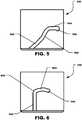
- FIG. 5illustrates one such groove, generally designated 500.
- the groove 500can include a generally helical portion 502 that extends to a relatively straight portion 504.
- the relatively straight portion 504can be substantially parallel to the end face of the outlet tube 340.
- a spring in a valve assemblycan provide a biasing force to facilitate locking the paint cup assembly 104 ( FIG. 3 ) within the adapter 106 ( FIG. 3 ).
- the relatively straight portion 504can be slightly angled with respect to the end face of the outlet tube 340 in order to provide a ramped structure to further facilitate locking the paint cup assembly 104 ( FIG. 3 ) within the adapter 106 ( FIG. 3 ).
- the relatively straight portion 504can be angled in a range of one degree to twenty degrees (1°-20°) relative to a line parallel to the end face of the outlet tube 340.
- the relatively straight portion 504can terminate in a notch 506, or divot.
- a locking pincan move into the notch 506 and can further secure attachment of the paint cup assembly 104 ( FIG. 3 ) to the adapter ( FIG. 3 ).
- FIG. 6illustrates another groove, generally designated 600.
- the groove 600can include a vertical portion 602 that can be substantially perpendicular to the end face of the outlet tube 304.
- the vertical portion 602leads to a first angled portion 604 that can be angled away from the end face of the outlet tube 304, e.g., in a range of one degree to twenty degrees (1°-20°).
- the first portion 604can be angled with respect to a line parallel to the end face of the outlet tube 304.
- a second angled portion 606extends from the first angled portion 604 in the opposite direction as the first angled portion 604, i.e., toward the end face of the outlet tube 304.
- the second angled portion 606can be angled in a range of one degree to twenty degrees (1°-20°).
- the second angled portion 606can be angled with respect to a line parallel to the end face of the outlet tube 304.
- the cap 206can be constructed from polypropylene (PP).
- the paint cup assembly 104can also include a valve assembly 350.
- the valve assembly 350can be installed within the cap 206. Specifically, the valve assembly 350 can be installed within the cap 206 between the outlet tube 340 and a valve retainer 352.
- the valve assembly 350can include a plunger 354 and a spring 356.
- the valve assembly 350can include a ball (not illustrated) in lieu of a plunger.
- the plunger 354can be constructed from a thermoplastic elastomer (TPE).
- the spring 365can be a conical compression spring made from stainless steel.
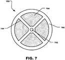
- the valve retainer 352include a generally disk shaped frame 700.
- the frame 700 of the valve retainer 352can be formed with a central opening 702 through which a portion of the plunger 354 can extend through after installation and during operation of the valve assembly 350, as described below.
- FIG. 7depicts that the frame 700 of valve retainer 352 can include one or more windows 704, or openings, formed therein.
- a filter material 706, e.g., a mesh type material,can be disposed within each window 704.
- the frame 700can include an upper portion and a lower portion and the filter material 706 can be sandwiched there between.
- the frame 700can be a single piece and formed with the windows 704 and the filter material 706 can be welded to an upper surface or lower surface of the frame 700.
- the frame 700 of the valve retainer 352can be constructed from polypropylene.
- the filter material 706can be a mesh type material suitable for filtering a fluid such as paint.
- the plunger 354can include a shaft 800 that can include a proximal end 802 and a distal end 804.
- a head 806can extend from the distal end 804 of the shaft 800.
- the head 806 of the plunger 354can include a proximal end 808 and a distal end 810.
- a sealing collar 812can extend radially from the proximal end 808 of the head 806.
- the sealing collar 812can be formed with a sealing face 814.
- the sealing face 814 of the sealing collar 812can be configured to engage a valve seat, described below, formed in the outlet tube 340 ( FIG. 3 ) of the cap 206 ( FIG. 3 ). When the sealing face 814 engages the valve seat, flow through the outlet tube 340 ( FIG. 3 ) can be substantially blocked and the paint cup assembly 104 ( FIG. 3 ) can be sealed.
- FIG. 8depicts that the head 806 of the plunger 354 can be formed with one or more flutes 816.
- the flutes 816can facilitate fluid flow through the paint cup assembly 104 ( FIG. 3 ) when the sealing face 814 is disengaged from the valve seat.
- the paint cup assembly 104can further include the adapter 106.
- a valve actuator 850can be installed within the adapter 106.
- FIG. 9illustrates further details concerning the valve actuator 850 and
- FIG. 10illustrates further details regarding the adapter 106.
- the valve actuator 850can include a generally cylindrical, base 900.
- a generally cylindrical, hollow post 902can extend from the base 900.
- the base 900can be formed with a central bore 904.
- the post 902can be formed with one or more slots 906, or openings.
- the slots 906are configured to allow fluid, e.g., paint, to flow through the post 902 and the base 900 when the valve assembly 350 ( FIG. 3 ) is in the open configuration.
- the post 902can be configured to engage the plunger 354 ( FIG. 3 , FIG. 8 ) and move the plunger 354 linearly in order to disengage the sealing face 814 ( FIG. 8 ) of the plunger 354 ( FIG. 8 ) from the valve seat, described in detail below in conjunction with FIG. 13 .
- valve actuator 850can be constructed from nylon.
- FIG. 10depicts details concerning the construction of the adapter 106.
- the adapter 106can include an adapter body 1000 that can define a proximal end 1002 and a distal end 1004. Further, the adapter 106 can include an internal bore 1006 along the length of the adapter body 1000.
- the internal bore 1006can include a first bore portion 1008 that can extend from the proximal end 1002 of the adapter body 1000 toward the distal end 1004 of the adapter body 1000.
- the internal bore 1006can include a second bore portion 1010 that can extend from the first bore portion 1008 toward the distal end 1004 of the adapter body 1000.
- a third bore portion 1012can extend from the second bore portion 1010 and terminate at the distal end 1004 of the adapter body 1000.
- the base 900 ( FIG. 9 ) of the valve actuator 354 ( FIG. 3 )can be sized and shaped to fit into the second bore portion 1010 of the internal bore 1006 formed in the adapter body 1000. Moreover, the base 900 ( FIG. 9 ) of the valve actuator 354 ( FIG. 3 ) can be press fitted into the second bore portion 1010.
- the first bore portion 1008can be formed with one or more grooves 1016 that can be configured to engage one or more locking pins 400 ( FIG. 4 ) that extend radially outward from the outlet tube 340 ( FIG. 4 ) of the cap 206 ( FIG. 3 ).
- the groove 1016can include a generally helical portion 1018 that can extend to a relatively straight portion 1020.
- the relatively straight portion 1020can be substantially parallel to the end face of the adapter 106.
- the paint cup assembly 104( FIG. 3 ) can be rotated in order to move the locking pins 400 ( FIG. 4 ) within the grooves 1016 until the paint cup assembly 104 ( FIG. 3 ) is essentially locked in placed within the adapter 106 ( FIG. 3 ).
- the relatively straight portion 1020can be slightly angled toward to the end face of the adapter 106 in order to provide a ramped structure to further facilitate locking the paint cup assembly 104 ( FIG. 3 ) within the adapter 106 ( FIG. 3 ).
- the relatively straight portion 1020can be angled in a range of one degree to twenty degrees (1°-20°) relative to a line parallel to the end face of the adapter 106.
- the relatively straight portion 1020can terminate in a notch 1022, or divot. A locking pin can move into the notch 1022 and can further secure attachment of the paint cup assembly 104 ( FIG. 3 ) to the adapter 106 ( FIG. 3 ).
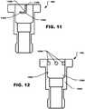
- FIG. 11illustrates another groove, generally designated 1100, that can be formed in the adapter 106.
- the groove 1100can include a vertical portion 1102 that can be substantially perpendicular to the end face of the adapter 106.
- the vertical portion 1102leads to a first angled portion 1104 that can be angled away from the end face of the adapter 106, e.g., in a range of one degree to twenty degrees (1°-20°).
- the first portion 1104can be angled with respect to a line parallel to the end face of the adapter 106.
- a second angled portion 1106can extend from the first angled portion 1104 in the opposite direction as the first angled portion 1104, i.e., toward the end face of the adapter 106.
- the second angled portion 1106can be angled in a range of one degree to twenty degrees (1°-20°).
- the second angled portion 1106can be angled with respect to a line parallel to the end face of the adapter 106.
- the adapter 106can be formed within one or more locking pins 1200 that can extend radially inward from the adapter body 1000.
- the locking pins 1200can extend radially inward from the wall of the first bore portion 1008 of the internal bore 1006 formed in the adapter body 1000.
- the locking pins 1200can be configured to engage one or more grooves, or slots, formed within the outlet tube 340 of the cap 206.
- the adapter 106can be constructed from a metal, such as aluminum.
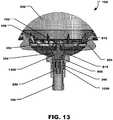
- FIG. 13depicts the outlet tube 340 of the cap 206 inserted into the first bore portion 1008 of the internal bore 1006 formed in the adapter 106.
- the valve actuator 850 within the adapter 106can engage the plunger 354 of the valve assembly 350.
- the post 902 of the valve actuator 850can contact and engage the head 806 of the plunger 354.
- the post 902 of the valve actuator 850can cause the plunger 354 to move linearly into the cap 206 and through the valve retainer 352, e.g., through the central opening 702 of the valve retainer 352.
- the spring 356can be compressed between the valve retainer 352 and the head 806 of the plunger 354.
- the sealing face 814 formed on the sealing collar 812 of the head 806can be unseated, or otherwise disengaged, from a valve seat 1300 formed within the cap 206 at the base of the outlet tube 340.
- fluide.g., paint
- fluidcan flow from the paint liner 202 through the cap 206 and out of the outlet tube 340.
- the fluidcan then flow through the valve actuator 850 and through the adapter 106 into a paint sprayer.
- the filter material 706FIG. 7
- the valve retainer 352can filter the fluid, e.g., to remove any dirt, dust, or other particles.
- the valve assembly 350can be configured to be operable from a closed configuration in which fluid flow through the outlet tube 340 can be prevented to an open configuration in which fluid flow through the outlet tube 340 can be permitted upon engagement with a paint sprayer.
- the open configurationcan be achieved automatically during engagement of the paint cup assembly 104 with the adapter 106 or paint sprayer (not illustrated).
- the engagementcan be achieved by reducing a distance between the paint cup assembly and the adapter 106 or paint sprayer (not illustrated).
- engagementcan include an interference fi.
- engagementcan include a threaded engagement.
- valve assembly 1400can include a membrane 1402 disposed within an outlet tube 1404 of a cap (not illustrated).
- the membrane 1402can be self-sealing when a trocar is removed therefrom.
- the valve assembly 1400can further include a trocar 1406 or a similarly configured needle or piercing hollow shaft.
- the trocar 1406can be disposed within an internal bore 1408 of an adapter 1410.
- the trocar 1406can be supported by one or more support structures 1412 that extend radially from a base of the trocar 1406 to the wall of the internal bore 1408.
- the outlet tube 1404 of the capcan be inserted into the internal bore 1408 of the adapter 1410. Further, as the outlet tube 1404 is pushed into the adapter, the trocar 1406 can pierce the membrane 1402 in order to permit fluid flow out of the paint cup assembly (not illustrated) and through the adapter 1410 into a paint sprayer (not illustrated).
- the trocar 1406When the paint cup assembly (not illustrated) is disengaged from the adapter 1410, the trocar 1406 can be retracted, or otherwise removed, from the membrane 1402. Once the trocar 1406 is removed from the membrane 1402, the membrane 1402 can seal the hole formed at the location within the membrane 1402 in which the trocar 1406 pierced the membrane 1402. As such, if the paint cup assembly (not illustrated) remains at least partially filled with fluid, leakage of the fluid can be substantially minimized.
- the paint cup assembly 1500can include a paint liner 1502.
- a ring 1504can fit around an end of the paint liner 1502. Further, the ring 1504 can threadably engage a cap 1506 and capture the end of the pain liner 1502 between the ring 1504 and the cap 1506.
- the cap 1506can be configured to engage an adapter 1508.
- the paint liner 1502can be substantially similar to the paint liner 202 described above.
- the ring 1504can be similar in construction to the hub 312 of the extended ring 204 described above.
- the extended ring 204can be included in the paint cup assembly 1500.
- the cap 1506can include a proximal end 1510 and a distal end 1512. Further, the cap 1506 can include a generally flat surface 1514 at the distal end 1512 and an outlet tube 1516 can extend from the generally flat surface 1514 of the cap 1506. In a particular aspect, the cap 1506 can include many, if not all, of the features described above in conjunction the cap 206 illustrated in FIG. 3 .
- the cap 1506also includes a structural feature 1520 that can extend from the flat surface 1514 of the cap 1506.
- the structural feature 1500can be a protrusion, a recess, or a combination thereof. Further, the structural feature 1500 can include multiple protrusions, recesses, or combinations thereof.
- the structural feature 1520can be formed adjacent to, or near, the outlet tube 1516 of the cap 1506. Specifically, the structural feature can be formed adjacent to an outer perimeter of the outlet tube 1516.
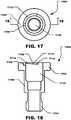
- FIG. 17 and FIG. 18indicate that the adapter 1508 can include an adapter body 1700 that can have a proximal end 1702 and a distal end 1704. Further, the adapter 1508 can include a top face 1706 at the proximal end 1702 of the adapter 1508. As illustrated in FIG. 17 and FIG. 18 , the adapter 1508 includes a complementary structural feature 1708 formed in the top face 1706 of the adapter 1508 adjacent to a bore 1710 that extends through the adapter body 1700.
- the complementary structural feature 1708can be a protrusion, a recess, or a combination thereof. Further, the complementary structural feature 1708 can include multiple protrusions, recesses, or combinations thereof.
- the complementary structural feature 1708can be configured to engage the structural feature 1520 formed on the cap 1506.
- the complementary structural feature 1708can be formed on a paint spray gun, at or near a paint inlet thereof.
- the adapter 1508can be include a ramped portion 1712 that can be formed in the top face 1706 of the adapter 1508 adjacent to the complementary structural feature 1708.
- the ramped portion 1712can engage the structural feature 1520 on the cap 1506 in order to increase a first rotational resistance, described below, that can be felt by the user as the paint cup assembly 1500 is engaged with the adapter 1508.
- the ramped portion 1602can be formed at an angle, ⁇ , with respect to the top face 1706 of the adapter and ⁇ can be ⁇ 1°, such as ⁇ 2°, or ⁇ 3°.
- ⁇can be ⁇ 10°, such as ⁇ 9°, ⁇ 8°, ⁇ 7°, ⁇ 6°, or ⁇ 5°. In a particular aspect, ⁇ can be within a range between and including any of the values for ⁇ described above.
- the ramped portion 1712can include a proximal end 1714 adjacent to the complementary structural feature 1708 and the ramped portion 1712 can extend to a distal end 1716 that is distanced from the complementary structural feature 1708.
- a distance between the ramped portion 1602 and the top face 1706 of the adapter 1508can increase from the proximal end 1714 of the ramped portion 1712 to the distal end 1716 of the ramped portion 1712.
- the structural feature 1520 on the cap 1506can move across the ramped portion 1712 before the structural feature snaps into, or otherwise engages, the complementary structural feature 1708 on the adapter 104.
- the structural feature 1520 on the cap 1506moves across the ramped portion 1712 that angle of the ramped portion 1712 can cause the ramped portion 1712 act as a wedge against the structural feature 1520 and increase the rotational resistance experienced by a user.
- a similar ramped portioncan be formed on the cap 1506 of the paint cup assembly 1500 adjacent to the structural feature 1520 formed thereon.
- the structural features 1520, 1708can cooperate with each other to form a tactile feedback mechanism that can provide a tactile indication to a user that can be felt by the user while the user is engaging the spray cup assembly 1500 with a paint sprayer, e.g., directly to the paint sprayer or indirectly to the paint sprayer via an adapter 1508.
- the tactile indicationcan include two stages. First, the tactile indication can provide a first rotational resistance to the user. The first rotational resistance can require a torque to overcome that is greater than the normal engagement torque required to rotate the paint cup assembly 1500 relative to the adapter 1508 without the tactile feedback mechanism. The second rotational resistance can be substantially less than the first rotational resistance and can occur when the structural feature 1520 on the paint cup assembly 1500 engages the complementary structural feature 1708 on the adapter 1508.
- the tactile indicationcan occur within at least about 1° from an end of rotation of the paint cup assembly with respect to the paint spray gun, such at least about 2°, at least about 3°, at least about 4°, at least about 5°, at least about 10°, at least about 15°, or even at least about 20°. Further, the tactile indication can occur within no greater than 180° from an end of rotation of the paint reservoir assembly with respect to the paint spray gun, such as no greater than about 170°, no greater than about 160°, no greater than about 150°, no greater than about 100°, no greater than about 60°, or no greater than about 45°. The tactile indication can occur within a range between and including 1° to 180° from an end of rotation of the paint cup assembly 1500 with respect to the adapter 1508 or paint spray gun.
- the tactile indicationprior to complete engagement of the paint reservoir assembly with the paint spray gun, includes a first rotational resistance followed by a second rotational resistance.
- the first torsional resistanceis greater than the second torsional resistance.
- the first rotational resistancecan be at least about 2 times greater than the second rotational resistance, at least about 3 times, or at least about 5 times.
- the first rotational resistancecan be not greater than about 10 times greater than the second rotational resistance, not greater than 8 times, or not greater than 7 times.
- the first rotational resistancecan be within a range between and including at least about 2 times greater than the second rotational resistance and not greater than about 10 times greater than the second rotational resistance.
- the first rotational resistancecan be greater than a normal engagement resistance between the paint cup assembly and the paint spray gun prior to the occurrence of the tactile indication.
- the first rotational resistancecan be at least about 2 times greater than the normal engagement resistance, at least about 3 times greater, at least about 4 times greater, or at least about 5 times greater.
- the first rotational resistancecan not greater than about 10 times greater than the normal engagement resistance, not greater than 8 times, or not greater than 7 times.
- the first rotational resistancecan be within a range between and including at least about 2 times greater than the normal engagement resistance and not greater than about 10 times greater than the normal engagement resistance.
- the first torsional resistancecan occur within at least about 10° from the end of rotation of the paint reservoir assembly with respect to the paint spray gun, at least about 15°, at least about 20°, or at least about 30°. Further, the first torsional resistance occurs within no greater than about 180° from the end of rotation of the paint reservoir assembly with respect to the paint spray gun, no greater than about 90°, no greater than about 60°, or no greater than about 45°. The first torsional resistance can occur within a range between and including 10° and 180° from the end of rotation. The end of rotation occurs when the paint cup assembly is fully engaged with the paint spray gun.
- the second torsional resistancecan occur within at least about 1° of the end of rotation of the paint reservoir assembly with respect to the paint spray gun, at least about 2°, at least about 3°, or at least about 5°. Moreover, the second torsional resistance occurs within no greater than about 10° of the end of rotation of the paint reservoir assembly with respect to the paint spray gun, no greater than about 9°, no greater than about 8°, or no greater than about 7°. The second torsional resistance can occur within a range between and including 1° and 10° from the end of rotation.
- the tactile indicationis configured to prevent a user from over engaging the cap with respect to the paint spray gun. Further, the tactile indication is configured to prevent a user from over tightening the cap with respect to the paint spray gun.
- the tactile indicationcan provide a signal to a user to cease an engagement operation between the paint reservoir assembly and the paint spray gun.
- the engagement operationcan include angular motion between the paint reservoir assembly and the paint spray gun.
- the engagement operationcan include linear motion between the paint reservoir assembly and the paint spray gun.
- the engagement operationcomprises a combination of angular motion and linear motion between the cap and the paint inlet.
- the tactile indicationcan be felt by a user just prior to the paint reservoir assembly properly engaging the paint spray gun.
- the tactile indicationcan include a snap that is felt by a user just before, or as, a paint reservoir assembly reaches full engagement with the paint spray gun.
- the tactile indicationcan be a vibration.
- the vibrationcan be a mechanical vibration or a sonic vibration.
- the vibrationcan be a click, or a series of clicks, that can be felt by a user, heard by a user, or a combination thereof. Further, the vibration can be felt by the user through the paint cup assembly.
- a torque diagram showing the engagement torque of a paint cup assembly, or paint reservoir assembly, with a paint spray gun or adapteris shown.
- the torque diagramshows the engagement torque plotted versus angular rotation of the paint cup assembly relative to the paint spray gun.
- the torque diagramshows a first portion 1902 that represents the normal torque required to overcome the normal engagement resistance of the paint cup assembly relative to the paint spray gun.
- the normal engagement resistanceis that resistance provided by the engagement of male threads on the paint cup assembly with female threads on the adapter, e.g., before the structural feature on the cap begins sliding against the ramped portion on the adapter.
- the torque diagram 1900can include a second portion 1904.
- the second portionrepresents the torque required to overcome the first rotational resistance provided by the structural feature 1520 on the paint cup assembly 1500 and the ramped portion 1712 of the adapter 1508 just before to the structural feature 1520 on the paint cup assembly 1500 engages the complementary structural feature 1708 on the adapter 1508.
- the torque diagram 1900can also include a third portion 1906 that represents the torque required to overcome the second rotational resistance that occurs after the structural feature 1520 on the paint cup assembly 1500 4 engages the structural feature 1708 on the adapter 1508. As shown, the second rotational resistance is substantially less than the first rotational resistance.
- the torque diagram 1900includes a spike 1908 in the torque that would occur if a user attempted to over-rotate the paint cup assembly 1500 with respect to the adapter 1508.
- the paint cup assemblyprovides a paint cup assembly that is substantially leak-proof regardless of the orientation of the paint cup assembly.
- the paint cup assemblyalso provides a tactile feed back mechanism that can prevent a user from over-tightening the paint cup assembly when engaging the paint cup assembly with a paint spray gun via an adapter.
- the paint cup assemblycan be connected to a paint spray gun while the paint spray gun is in an upright position typically used while expelling paint from the paint spray gun.
- the valvemaintains paint within the paint cup assembly until the paint cup assembly is engaged with the paint spray gun and the adapter opens the valve. Further, when the paint cup assembly is disengaged with the paint spray gun, the valve returns to a closed position and seals the outlet of the paint cup assembly.
- the paint cup assemblycan be stored for later use and any remaining paint can stay fresh and usable for an extended period of time.
- the paint spray guncan incorporate one or more of the features of the adapter and in such an aspect, the paint cup assembly can be directly engaged with the paint spray gun without using the adapter. Accordingly, a post within the paint spray gun can be configured to open the valve when the paint cup assembly is directly engaged with the paint spray gun.
Landscapes
- Nozzles (AREA)
Description
- The present disclosure is directed to a paint cup assembly and to a paint cup assembly having a tactile feedback mechanism.
- Spray guns can be used for rapidly coating surfaces with liquids, such as paint. Paint can be contained in a container that attaches to the spray gun. The outlet of the container can be a releasably connectable coupling that connects to the spray gun. Paint can flow from the container into the spray gun and then, fed to a spray nozzle. The spray nozzle can combine the paint with air, atomize the liquid, and form a spray. At the end of the spraying operation, the container and the mating connection to the spray gun should be thoroughly cleaned so that the paint from one operation does not contaminate the paint to be sprayed in the next spraying operation. Additionally, the coupling between container and spray gun should be free of any dried liquid that might interfere with the connection between container and spray gun. A container with a lid and a disposable cup or liner can be used to eliminate or reduce the labor required to clean the container and the coupling to the spray gun.
WO 2005/120718 A1 refers to an adapter assembly for connecting a fluid supply assembly to a fluid applicator.WO 2004/037433 A1 refers to the connection between a spray gun and a reservoir containing the liquid to be sprayed. - Embodiments are illustrated by way of example and are not limited in the accompanying figures.
FIG. 1 includes a plan view of a paint sprayer assembly in accordance with a particular embodiment.FIG. 2 includes a plan view of a paint cup assembly engaged with an adapter in accordance with a particular embodiment.FIG. 3 includes an exploded plan view of a paint cup assembly and an adapter in accordance with a particular embodiment.FIG. 3a includes a detailed cross-sectional view of a paint liner.FIG. 4 includes a detailed plan view of a paint cup assembly outlet tube in accordance with a particular embodiment.FIG. 5 includes a detailed plan view of a paint cup assembly outlet tube in accordance with another particular embodiment.FIG. 6 includes a detailed plan view of a paint cup assembly outlet tube in accordance with a yet another particular embodiment.FIG. 7 includes a plan view of a valve retainer in accordance with a particular embodiment.FIG. 8 includes a cross-sectional view of a valve plunger in accordance with a particular embodiment.FIG. 9 includes a cross-sectional view of a valve actuator in accordance with a particular embodiment.FIG. 10 includes a cross-sectional view of an adapter in accordance with a particular embodiment.FIG. 11 includes a cross-sectional view of an adapter in accordance with another particular embodiment.FIG. 12 includes a cross-sectional view of an adapter in accordance with yet another particular embodiment.FIG. 13 includes a cross-sectional view of the paint cup assembly taken along line 13-13 inFIG. 2 in accordance with a particular embodiment.FIG. 14 includes a detailed plan view of a paint cup assembly valve assembly in accordance with another particular embodiment.FIG. 15 includes a plan view of a paint cup assembly in accordance with another particular embodiment.FIG. 16 includes another plan view of a paint cup assembly in accordance with a particular embodiment.FIG. 17 includes a plan view of an adapter in accordance with another particular embodiment.FIG. 18 includes a cross-sectional view of an adapter in accordance with a particular embodiment taken along Line 18-18 inFIG. 17 .FIG. 19 includes a graph showing torque and angular rotation during engagement of an embodiment of a paint cup assembly in accordance with a particular embodiment with a paint spray gun.- Skilled artisans appreciate that elements in the figures are illustrated for simplicity and clarity and have not necessarily been drawn to scale. For example, the dimensions of some of the elements in the figures can be exaggerated relative to other elements to help to improve understanding of embodiments of the invention. The use of the same reference symbols in different drawings indicates similar or identical items.
- The following description in combination with the figures is provided to assist in understanding the teachings disclosed herein. The following discussion will focus on specific implementations and embodiments of the teachings. This focus is provided to assist in describing the teachings and should not be interpreted as a limitation on the scope or applicability of the teachings.
- As used herein, the terms "comprises," "comprising," "includes, " "including, " "has, " "having," or any other variation thereof, are intended to cover a non-exclusive inclusion. For example, a process, method, article, or apparatus that comprises a list of features is not necessarily limited only to those features but can include other features not expressly listed or other features that are inherent to such process, method, article, or apparatus. Further, unless expressly stated to the contrary, "or" refers to an inclusive-or and not to an exclusive-or. For example, a condition A or B is satisfied by any one of the following: A is true (or present) and B is false (or not present), A is false (or not present) and B is true (or present), and both A and B are true (or present).
- The use of "a" or "an" is employed to describe elements and components described herein. This is done merely for convenience and to give a general sense of the scope of the embodiments of the disclosure. This description should be read to include one or at least one and the singular also includes the plural, or vice versa, unless it is clear that it is meant otherwise.
- Unless otherwise defined, all technical and scientific terms used herein have the same meaning as commonly understood by one of ordinary skill in the art to which this disclosure belongs. The materials, methods, and examples are illustrative only and not intended to be limiting.
- Referring initially to
FIG. 1 , a paint sprayer assembly is illustrated and is generally designated 100. As illustrated, thepaint sprayer assembly 100 includes apaint spray gun 102 and apaint cup assembly 104 that can be removably engaged with thepaint spray gun 102 via anadapter 106. In a particular aspect, theadapter 106 can be threadably engaged with thepaint spray gun 102 and thepaint cup assembly 104 can be inserted into theadapter 104. Further, during operation of thepaint spray gun 102, thepaint cup assembly 104 can be in fluid communication with thepaint spray gun 102. Specifically, thepaint cup assembly 104 can deliver paint to thepaint spray gun 102 and thepaint spray gun 102 can be used to transmit the fluid, e.g., paint, to a substrate, e.g., a car body. FIG. 2 through FIG. 9 illustrate details concerning thepaint cup assembly 104 that is depicted inFIG. 1 in conjunction with thepaint spray gun 102. Specifically,FIG. 2 andFIG. 3 include details concerning thepaint cup assembly 104 in its entirety andFIG. 4 through FIG. 9 illustrate details concerning various component parts of thepaint cup assembly 104.- As indicated in
FIG. 2 andFIG. 3 , thepaint cup assembly 104 includes a paint reservoir, e.g., apaint liner 202. Thepaint cup assembly 104 can also include an extendedring 204 that can at least partially surround thepaint liner 202. In a particular aspect, the extendedring 204 can include an axial extension, e.g., a skirt, that can extend toward a closed proximal end of the paint liner such that the ring can be configured to allow a user to grasp the paint cup assembly without collapsing the paint liner during attachment with a paint sprayer. As illustrated, thepaint cup assembly 104 includes acap 206 that can be threadably engaged with the extendedring 204. As described in detail below, thecap 206 can engage theadapter 106 in order for thepaint cup assembly 104 to be attached to a spray gun (not illustrated). FIG. 3 indicates that thepaint liner 202 can include ahollow body 302 that defines aproximal end 304 and adistal end 306. Thehollow body 302 can be generally frustoconical. Theproximal end 304 of thehollow body 302 can be closed. Further, theproximal end 304 of thehollow body 302 can be rounded. Thedistal end 306 of thehollow body 302 can be open and can facilitate filling thepaint liner 202 with paint, as described in detail below. Thehollow body 302 can also include arim 308 that circumscribes thedistal end 306 of thehollow body 302. When theextended ring 204 is engaged with thecap 206, therim 308 of thepaint liner 202 can be captured, or otherwise trapped, between theextended ring 204 and thecap 206.- In a particular aspect, the
paint liner 202, including thehollow body 302, can be transparent. In another aspect, thepaint liner 202, including thehollow body 302, can be translucent. In still another aspect, thepaint liner 202, including thehollow body 302, can be opaque. In still another aspect, portions of thepaint liner 202 can be opaque and other portions can be transparent, translucent, or a combination thereof. For example, thepaint liner 202 can substantially opaque with one or more transparent strips to facilitate measuring while filling thepaint liner 202 with paint. - In a particular aspect, the
paint liner 202 can be disposable. Further, in a particular aspect, thepaint liner 202 can be collapsible. Specifically, thepaint liner 202 can be collapsible as paint is withdrawn from within thepaint liner 202. Also, in a particular aspect, thepaint liner 202 can be constructed from low density polyethylene (LDPE). - As illustrated in
FIG. 3 , thepaint liner 202 can include a plurality ofindicia 310 spaced along the length of thehollow body 302 of thepaint liner 202. Each of the indicia can be space along the length of thehollow body 302. Each of theindicia 310 can represent an incremental change in an internal volume of the paint liner. In a particular aspect, the plurality ofindicia 310 can be lines that are printed, or otherwise disposed, on an exterior surface of thebody 302. In another aspect, the plurality ofindicia 310 can be printed, or otherwise disposed, on an interior surface of thebody 302. In still another aspect, the plurality ofindicia 310 can be printed, or otherwise disposed, on an interior surface of thebody 302 and on an exterior surface of thebody 302. Theindicia 310 can partially circumscribe thebody 302. Alternatively, theindicia 310 can fully circumscribe thebody 302. - It can be appreciated that the volume between adjacent indicia can be the same. Further, it can be appreciated that due to the tapered shape of the
body 302 the spacing of the indicia along the body can vary. - In a particular aspect, each of the plurality of
indicia 310 can be a raised rib extending from the body. Each of the ribs can extend internally into the body. Conversely, each of the ribs can extend externally, or outwardly, from the body. - In another aspect, each of the
indicia 310 can serve as a crush zone to facilitate collapsing of thepaint liner 202 as paint is expressed from thepaint liner 202 during a spraying operation. As illustrated inFIG. 3a , thebody 302 of thepaint liner 202 can have a body wall thickness, tBW, and each of theindicia 310 can have an indicia wall thickness, tIW, and the indicia wall thickness can be less than the body wall thickness. - In a particular aspect, the indicia wall thickness can be less than or equal to ninety percent (90%) of the body wall thickness. In another aspect, the indicia wall thickness can be less than or equal to eighty-five percent (85%) of the body wall thickness. In yet another aspect, the indicia wall thickness can be less than or equal to eighty percent (80%) of the body wall thickness. In still another aspect, the indicia wall thickness can be less than or equal to seventy-five percent (75%) of the body wall thickness. In another aspect, the indicia wall thickness can be less than or equal to seventy percent (70%) of the body wall thickness. In still yet another aspect, the indicia wall thickness can be less than or equal to sixty-five percent (65%) of the body wall thickness. In yet another aspect, the indicia wall thickness can be less than or equal to sixty percent (60%) of the body wall thickness.
- In another aspect, the indicia wall thickness can be less than or equal to fifty-five percent (55%) of the body wall thickness. In still another aspect, the indicia wall thickness can be less than or equal to fifty percent (50%) of the body wall thickness. In another aspect, the indicia wall thickness can be less than or equal to forty-five percent (45%) of the body wall thickness. In another aspect, the indicia wall thickness can be less than or equal to forty percent (40%) of the body wall thickness. In yet another aspect, the indicia wall thickness can be less than or equal to thirty-five percent (35%) of the body wall thickness. Further, in another aspect, the indicia wall thickness can be less than or equal to thirty percent (30%) of the body wall thickness. In still another aspect, the indicia wall thickness can be less than or equal to twenty-five percent (25%) of the body wall thickness. In another aspect, the indicia wall thickness may not be less than twenty percent (20%) of the body wall thickness. Further, the indicia wall thickness can be within a range between and including any of the percentage of body wall thickness values described herein.
- Returning to
FIG. 3 , theextended ring 204 can include ahub 312 having aproximal end 314 and adistal end 316. As illustrated, askirt 318 can extend longitudinally from theproximal end 314 of thehub 312. Theskirt 318 can be formed with a plurality ofslots 320. Theslots 320 can allow a user to see theindicia 310 on thepaint liner 202 while filling thepaint liner 202 with paint. FIG. 3 indicates that thedistal end 316 of thehub 312 can be formed with a plurality ofteeth 322 that extend radially outward from thehub 312. Accordingly, when viewed from thedistal end 316, thehub 312 of theextended ring 204 can have a gear, or cog, shape. This gear, or cog, shape can be configured to key thepaint cup assembly 104 to a filling station, described in detail below, during filling. Specifically, the gear shape can be configured to fit into a correspondingly shaped hole formed in a filling station in order to prevent thepaint cup assembly 104 from rotating within the hole as theextended ring 204 is engaged with thecap 206.- The
hub 312 can include an interior surface (not illustrated) that can be formed with a plurality of internal threads. As such, thehub 312, and theextended ring 204, can be configured to threadably engage thecap 206. When assembled, as illustrated inFIG. 2 , theskirt 318 of theextended ring 204 can at least partially surround thepaint liner 202. Further, theskirt 318 can extend at least partially along the length of thepaint liner 202. In a particular aspect, theskirt 318 can be substantially rigid and theskirt 318 can be configured to be grasped without collapsing thepaint liner 202. Particularly, theextended ring 204 can be constructed from twenty percent (20%) talc filled polypropylene. - As further illustrated in
FIG. 3 , thecap 206 of thepaint cup assembly 104 can include generally hemispherical hollow body 329 having aproximal end 330 and adistal end 332. Theproximal end 330 of thecap 206 can be formed with a plurality ofexternal threads 334 that are configured to engage the internal threads (not illustrated) formed in thehub 312 of theextended ring 204. Thecap 206 can also include aprimary sealing structure 336 and asecondary sealing structure 338. Thecap 206 can also include an external rim 339 having an external diameter. Theprimary sealing structure 336 can be located at a distance from the external rim 339 and thesecondary sealing structure 338 can be located between theprimary sealing structure 336 and the external rim 339. - During use, the
extended ring 204 can be threaded onto thecap 206 and therim 308 of thepaint liner 202 can be sandwiched between theextended ring 204 and thecap 206. A primary seal can be established between therim 308 of thepaint liner 202 and theprimary sealing structure 336 on thecap 206. The primary seal can substantially prevent fluid from leaking through the interface established by thepaint liner 202 and thecap 206. A secondary seal can be established betweensecondary sealing structure 338 on thecap 206 and thehub 312 of theextended ring 204. The secondary seal can substantially prevent fluid from leaking through the interface established by thecap 206 and theextended ring 204. - Accordingly, when the
paint cup assembly 104 is filled with fluid and assembled as illustrated inFIG. 1 , thepaint cup assembly 104 can be shaken to stir, or otherwise mix, the fluid within thepaint cup assembly 104. - As illustrated in
FIG. 3 , thecap 206 can include anoutlet tube 340 that can extend from thedistal end 332 of thecap 206. Specifically, theoutlet tube 340 can extend from the center of thedistal end 332 of thecap 206. Theoutlet tube 340 can be configured to be removably engaged with theadapter 106. For example, as depicted inFIG.3 , theoutlet tube 340 can be formed withexternal threads 342. - Alternatively, as illustrated in
FIG. 4 , theoutlet tube 340 can be formed within one or more locking pins 400 that can extend radially outward from theoutlet tube 340. The locking pins 400 can be configured to engage one or more grooves, or slots, formed within theadapter 106. Examples of grooves or slots formed within theadapter 106 are described below in conjunction withFIG. 10 andFIG. 11 . - In another aspect, the
outlet tube 340 can be formed with one or more grooves configured to engage one or more locking pins within the adapter.FIG. 5 illustrates one such groove, generally designated 500. As such, thegroove 500 can include a generallyhelical portion 502 that extends to a relativelystraight portion 504. The relativelystraight portion 504 can be substantially parallel to the end face of theoutlet tube 340. To install the paint cup assembly 104 (FIG. 3 ) within the adapter 106 (FIG. 3 ), theoutlet tube 340 can be inserted into the adapter 106 (FIG. 3 ) such that thegroove 500, or grooves, fit over corresponding locking pins. Thereafter, the paint cup assembly 104 (FIG. 3 ) can be rotated in order to move thegroove 500, or grooves, over the locking pins until the paint cup assembly 104 (FIG. 3 ) is essentially locked in placed within the adapter 106 (FIG. 3 ). - It can be appreciated that a spring in a valve assembly, described below, can provide a biasing force to facilitate locking the paint cup assembly 104 (
FIG. 3 ) within the adapter 106 (FIG. 3 ). Further, it can be appreciated that the relativelystraight portion 504 can be slightly angled with respect to the end face of theoutlet tube 340 in order to provide a ramped structure to further facilitate locking the paint cup assembly 104 (FIG. 3 ) within the adapter 106 (FIG. 3 ). For example, the relativelystraight portion 504 can be angled in a range of one degree to twenty degrees (1°-20°) relative to a line parallel to the end face of theoutlet tube 340. Additionally, the relativelystraight portion 504 can terminate in anotch 506, or divot. A locking pin can move into thenotch 506 and can further secure attachment of the paint cup assembly 104 (FIG. 3 ) to the adapter (FIG. 3 ). FIG. 6 illustrates another groove, generally designated 600. As illustrated, thegroove 600 can include avertical portion 602 that can be substantially perpendicular to the end face of theoutlet tube 304. Thevertical portion 602 leads to a firstangled portion 604 that can be angled away from the end face of theoutlet tube 304, e.g., in a range of one degree to twenty degrees (1°-20°). Thefirst portion 604 can be angled with respect to a line parallel to the end face of theoutlet tube 304. A secondangled portion 606 extends from the firstangled portion 604 in the opposite direction as the firstangled portion 604, i.e., toward the end face of theoutlet tube 304. The secondangled portion 606 can be angled in a range of one degree to twenty degrees (1°-20°). The secondangled portion 606 can be angled with respect to a line parallel to the end face of theoutlet tube 304.- In a particular aspect, the
cap 206 can be constructed from polypropylene (PP). - Returning to
FIG. 3 , thepaint cup assembly 104 can also include avalve assembly 350. Thevalve assembly 350 can be installed within thecap 206. Specifically, thevalve assembly 350 can be installed within thecap 206 between theoutlet tube 340 and avalve retainer 352. Thevalve assembly 350 can include aplunger 354 and aspring 356. In another aspect, thevalve assembly 350 can include a ball (not illustrated) in lieu of a plunger. - In a particular aspect, the
plunger 354 can be constructed from a thermoplastic elastomer (TPE). Further, the spring 365 can be a conical compression spring made from stainless steel. - As illustrated in
FIG. 7 , thevalve retainer 352 include a generally disk shapedframe 700. Theframe 700 of thevalve retainer 352 can be formed with acentral opening 702 through which a portion of theplunger 354 can extend through after installation and during operation of thevalve assembly 350, as described below.FIG. 7 depicts that theframe 700 ofvalve retainer 352 can include one ormore windows 704, or openings, formed therein. Afilter material 706, e.g., a mesh type material, can be disposed within eachwindow 704. In a particular aspect, theframe 700 can include an upper portion and a lower portion and thefilter material 706 can be sandwiched there between. In another aspect, theframe 700 can be a single piece and formed with thewindows 704 and thefilter material 706 can be welded to an upper surface or lower surface of theframe 700. - In a particular aspect, the
frame 700 of thevalve retainer 352 can be constructed from polypropylene. Further, thefilter material 706 can be a mesh type material suitable for filtering a fluid such as paint. - As illustrated in
FIG. 8 , theplunger 354 can include ashaft 800 that can include aproximal end 802 and adistal end 804. Ahead 806 can extend from thedistal end 804 of theshaft 800. Thehead 806 of theplunger 354 can include aproximal end 808 and adistal end 810. A sealingcollar 812 can extend radially from theproximal end 808 of thehead 806. The sealingcollar 812 can be formed with a sealingface 814. The sealingface 814 of thesealing collar 812 can be configured to engage a valve seat, described below, formed in the outlet tube 340 (FIG. 3 ) of the cap 206 (FIG. 3 ). When the sealingface 814 engages the valve seat, flow through the outlet tube 340 (FIG. 3 ) can be substantially blocked and the paint cup assembly 104 (FIG. 3 ) can be sealed. FIG. 8 depicts that thehead 806 of theplunger 354 can be formed with one ormore flutes 816. Theflutes 816 can facilitate fluid flow through the paint cup assembly 104 (FIG. 3 ) when the sealingface 814 is disengaged from the valve seat.- Returning to
FIG. 3 , thepaint cup assembly 104 can further include theadapter 106. Avalve actuator 850 can be installed within theadapter 106.FIG. 9 illustrates further details concerning thevalve actuator 850 andFIG. 10 illustrates further details regarding theadapter 106. - As illustrated in
FIG. 9 , thevalve actuator 850 can include a generally cylindrical,base 900. A generally cylindrical,hollow post 902 can extend from thebase 900. As illustrated, the base 900 can be formed with acentral bore 904. Further, thepost 902 can be formed with one ormore slots 906, or openings. Theslots 906 are configured to allow fluid, e.g., paint, to flow through thepost 902 and the base 900 when the valve assembly 350 (FIG. 3 ) is in the open configuration. In a particular embodiment, thepost 902 can be configured to engage the plunger 354 (FIG. 3 ,FIG. 8 ) and move theplunger 354 linearly in order to disengage the sealing face 814 (FIG. 8 ) of the plunger 354 (FIG. 8 ) from the valve seat, described in detail below in conjunction withFIG. 13 . - In a particular aspect, the
valve actuator 850 can be constructed from nylon. FIG. 10 depicts details concerning the construction of theadapter 106. As illustrated, theadapter 106 can include anadapter body 1000 that can define aproximal end 1002 and adistal end 1004. Further, theadapter 106 can include aninternal bore 1006 along the length of theadapter body 1000. Theinternal bore 1006 can include afirst bore portion 1008 that can extend from theproximal end 1002 of theadapter body 1000 toward thedistal end 1004 of theadapter body 1000. Further, theinternal bore 1006 can include asecond bore portion 1010 that can extend from thefirst bore portion 1008 toward thedistal end 1004 of theadapter body 1000. Athird bore portion 1012 can extend from thesecond bore portion 1010 and terminate at thedistal end 1004 of theadapter body 1000.- In a particular aspect, the base 900 (
FIG. 9 ) of the valve actuator 354 (FIG. 3 ) can be sized and shaped to fit into thesecond bore portion 1010 of theinternal bore 1006 formed in theadapter body 1000. Moreover, the base 900 (FIG. 9 ) of the valve actuator 354 (FIG. 3 ) can be press fitted into thesecond bore portion 1010. - As illustrated in
FIG. 10 , thefirst bore portion 1008 can be formed with one ormore grooves 1016 that can be configured to engage one or more locking pins 400 (FIG. 4 ) that extend radially outward from the outlet tube 340 (FIG. 4 ) of the cap 206 (FIG. 3 ). Thegroove 1016 can include a generallyhelical portion 1018 that can extend to a relativelystraight portion 1020. The relativelystraight portion 1020 can be substantially parallel to the end face of theadapter 106. To install the paint cup assembly 104 (FIG. 3 ) within the adapter 106 (FIG. 3 ), the outlet tube 340 (FIG. 3 ) can be inserted into the adapter 106 (FIG. 3 ) such that the locking pins 400 (FIG. 4 ) fit into correspondinggrooves 1016. Thereafter, the paint cup assembly 104 (FIG. 3 ) can be rotated in order to move the locking pins 400 (FIG. 4 ) within thegrooves 1016 until the paint cup assembly 104 (FIG. 3 ) is essentially locked in placed within the adapter 106 (FIG. 3 ). - It can be appreciated that the relatively
straight portion 1020 can be slightly angled toward to the end face of theadapter 106 in order to provide a ramped structure to further facilitate locking the paint cup assembly 104 (FIG. 3 ) within the adapter 106 (FIG. 3 ). For example, the relativelystraight portion 1020 can be angled in a range of one degree to twenty degrees (1°-20°) relative to a line parallel to the end face of theadapter 106. Additionally, the relativelystraight portion 1020 can terminate in anotch 1022, or divot. A locking pin can move into thenotch 1022 and can further secure attachment of the paint cup assembly 104 (FIG. 3 ) to the adapter 106 (FIG. 3 ). FIG. 11 illustrates another groove, generally designated 1100, that can be formed in theadapter 106. As illustrated, thegroove 1100 can include avertical portion 1102 that can be substantially perpendicular to the end face of theadapter 106. Thevertical portion 1102 leads to a firstangled portion 1104 that can be angled away from the end face of theadapter 106, e.g., in a range of one degree to twenty degrees (1°-20°). Thefirst portion 1104 can be angled with respect to a line parallel to the end face of theadapter 106. A secondangled portion 1106 can extend from the firstangled portion 1104 in the opposite direction as the firstangled portion 1104, i.e., toward the end face of theadapter 106. The secondangled portion 1106 can be angled in a range of one degree to twenty degrees (1°-20°). The secondangled portion 1106 can be angled with respect to a line parallel to the end face of theadapter 106.- As illustrated in
FIG. 12 , in an alternative embodiment, theadapter 106 can be formed within one ormore locking pins 1200 that can extend radially inward from theadapter body 1000. For example, the locking pins 1200 can extend radially inward from the wall of thefirst bore portion 1008 of theinternal bore 1006 formed in theadapter body 1000. In a particular aspect, the locking pins 1200 can be configured to engage one or more grooves, or slots, formed within theoutlet tube 340 of thecap 206. - In a particular aspect, the
adapter 106 can be constructed from a metal, such as aluminum. - Referring now to
FIG. 13 , a detailed view of thepaint cup assembly 104 is illustrated.FIG. 13 depicts theoutlet tube 340 of thecap 206 inserted into thefirst bore portion 1008 of theinternal bore 1006 formed in theadapter 106. As theoutlet tube 340 is inserted into theadapter 106, thevalve actuator 850 within theadapter 106 can engage theplunger 354 of thevalve assembly 350. Specifically, thepost 902 of thevalve actuator 850 can contact and engage thehead 806 of theplunger 354. - The
post 902 of thevalve actuator 850 can cause theplunger 354 to move linearly into thecap 206 and through thevalve retainer 352, e.g., through thecentral opening 702 of thevalve retainer 352. As theplunger 354 moves as described, thespring 356 can be compressed between thevalve retainer 352 and thehead 806 of theplunger 354. Further, as theplunger 354 moves into thecap 206, the sealingface 814 formed on thesealing collar 812 of thehead 806 can be unseated, or otherwise disengaged, from avalve seat 1300 formed within thecap 206 at the base of theoutlet tube 340. - As the sealing
face 814 of thehead 806 is unseated from thevalve seat 1300 of theoutlet tube 340, fluid, e.g., paint, can flow from thepaint liner 202 through thecap 206 and out of theoutlet tube 340. The fluid can then flow through thevalve actuator 850 and through theadapter 106 into a paint sprayer. As the fluid flows through thecap 206, the filter material 706 (FIG. 7 ) disposed within thevalve retainer 352 can filter the fluid, e.g., to remove any dirt, dust, or other particles. - Accordingly, as illustrated in
FIG. 13 , thevalve assembly 350 can be configured to be operable from a closed configuration in which fluid flow through theoutlet tube 340 can be prevented to an open configuration in which fluid flow through theoutlet tube 340 can be permitted upon engagement with a paint sprayer. In particular, the open configuration can be achieved automatically during engagement of thepaint cup assembly 104 with theadapter 106 or paint sprayer (not illustrated). Further, it can be appreciated that the engagement can be achieved by reducing a distance between the paint cup assembly and theadapter 106 or paint sprayer (not illustrated). Further, in a particular embodiment, engagement can include an interference fi. In another aspect, engagement can include a threaded engagement. - Referring to
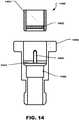
FIG. 14 , a third embodiment of a valve assembly is illustrated and is designated 1400. As illustrated, thevalve assembly 1400 can include amembrane 1402 disposed within anoutlet tube 1404 of a cap (not illustrated). In particular aspect, themembrane 1402 can be self-sealing when a trocar is removed therefrom. - The
valve assembly 1400 can further include atrocar 1406 or a similarly configured needle or piercing hollow shaft. Thetrocar 1406 can be disposed within aninternal bore 1408 of anadapter 1410. Thetrocar 1406 can be supported by one ormore support structures 1412 that extend radially from a base of thetrocar 1406 to the wall of theinternal bore 1408. - As a paint cup assembly (not illustrated) is engaged with the
adapter 1410, theoutlet tube 1404 of the cap (not illustrated) can be inserted into theinternal bore 1408 of theadapter 1410. Further, as theoutlet tube 1404 is pushed into the adapter, thetrocar 1406 can pierce themembrane 1402 in order to permit fluid flow out of the paint cup assembly (not illustrated) and through theadapter 1410 into a paint sprayer (not illustrated). - When the paint cup assembly (not illustrated) is disengaged from the
adapter 1410, thetrocar 1406 can be retracted, or otherwise removed, from themembrane 1402. Once thetrocar 1406 is removed from themembrane 1402, themembrane 1402 can seal the hole formed at the location within themembrane 1402 in which thetrocar 1406 pierced themembrane 1402. As such, if the paint cup assembly (not illustrated) remains at least partially filled with fluid, leakage of the fluid can be substantially minimized. - Referring now to
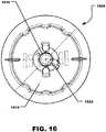
FIG. 15 through FIG. 17 , another embodiment of a paint cup assembly is shown and is generally designated 1500. As illustrated, thepaint cup assembly 1500 can include apaint liner 1502. Aring 1504 can fit around an end of thepaint liner 1502. Further, thering 1504 can threadably engage acap 1506 and capture the end of thepain liner 1502 between thering 1504 and thecap 1506. Thecap 1506 can be configured to engage anadapter 1508. - In a particular aspect, the
paint liner 1502 can be substantially similar to thepaint liner 202 described above. Further, thering 1504 can be similar in construction to thehub 312 of theextended ring 204 described above. In lieu of thering 1504 illustrated inFIG. 15 , theextended ring 204 can be included in thepaint cup assembly 1500. - In general, the
cap 1506 can include aproximal end 1510 and adistal end 1512. Further, thecap 1506 can include a generallyflat surface 1514 at thedistal end 1512 and anoutlet tube 1516 can extend from the generallyflat surface 1514 of thecap 1506. In a particular aspect, thecap 1506 can include many, if not all, of the features described above in conjunction thecap 206 illustrated inFIG. 3 . - In addition to those features, the
cap 1506 also includes astructural feature 1520 that can extend from theflat surface 1514 of thecap 1506. Thestructural feature 1500 can be a protrusion, a recess, or a combination thereof. Further, thestructural feature 1500 can include multiple protrusions, recesses, or combinations thereof. As illustrated inFIG. 15 andFIG. 16 , thestructural feature 1520 can be formed adjacent to, or near, theoutlet tube 1516 of thecap 1506. Specifically, the structural feature can be formed adjacent to an outer perimeter of theoutlet tube 1516. FIG. 17 and FIG. 18 indicate that theadapter 1508 can include anadapter body 1700 that can have aproximal end 1702 and adistal end 1704. Further, theadapter 1508 can include atop face 1706 at theproximal end 1702 of theadapter 1508. As illustrated inFIG. 17 and FIG. 18 , theadapter 1508 includes a complementarystructural feature 1708 formed in thetop face 1706 of theadapter 1508 adjacent to abore 1710 that extends through theadapter body 1700. The complementarystructural feature 1708 can be a protrusion, a recess, or a combination thereof. Further, the complementarystructural feature 1708 can include multiple protrusions, recesses, or combinations thereof. The complementarystructural feature 1708 can be configured to engage thestructural feature 1520 formed on thecap 1506. For a direct connection between thepaint cup assembly 1500 and a paint spray gun, the complementarystructural feature 1708 can be formed on a paint spray gun, at or near a paint inlet thereof.- As shown in
FIG. 17 and FIG. 18 , theadapter 1508 can be include a rampedportion 1712 that can be formed in thetop face 1706 of theadapter 1508 adjacent to the complementarystructural feature 1708. The rampedportion 1712 can engage thestructural feature 1520 on thecap 1506 in order to increase a first rotational resistance, described below, that can be felt by the user as thepaint cup assembly 1500 is engaged with theadapter 1508. The ramped portion 1602 can be formed at an angle, α, with respect to thetop face 1706 of the adapter and α can be ≥ 1°, such as ≥ 2°, or ≥ 3°. Further, α can be ≤ 10°, such as ≤ 9°, ≤ 8°, ≤ 7°, ≤ 6°, or ≤ 5°. In a particular aspect, α can be within a range between and including any of the values for α described above. - As depicted in
FIG. 18 , the rampedportion 1712 can include aproximal end 1714 adjacent to the complementarystructural feature 1708 and the rampedportion 1712 can extend to adistal end 1716 that is distanced from the complementarystructural feature 1708. A distance between the ramped portion 1602 and thetop face 1706 of theadapter 1508 can increase from theproximal end 1714 of the rampedportion 1712 to thedistal end 1716 of the rampedportion 1712. As thecap 1506 is engaged with theadapter 1508, thestructural feature 1520 on thecap 1506 can move across the rampedportion 1712 before the structural feature snaps into, or otherwise engages, the complementarystructural feature 1708 on theadapter 104. As thestructural feature 1520 on thecap 1506 moves across the rampedportion 1712 that angle of the rampedportion 1712 can cause the rampedportion 1712 act as a wedge against thestructural feature 1520 and increase the rotational resistance experienced by a user. - It can be appreciated that a similar ramped portion can be formed on the
cap 1506 of thepaint cup assembly 1500 adjacent to thestructural feature 1520 formed thereon. - In a particular aspect, the
structural features spray cup assembly 1500 with a paint sprayer, e.g., directly to the paint sprayer or indirectly to the paint sprayer via anadapter 1508. The tactile indication can include two stages. First, the tactile indication can provide a first rotational resistance to the user. The first rotational resistance can require a torque to overcome that is greater than the normal engagement torque required to rotate thepaint cup assembly 1500 relative to theadapter 1508 without the tactile feedback mechanism. The second rotational resistance can be substantially less than the first rotational resistance and can occur when thestructural feature 1520 on thepaint cup assembly 1500 engages the complementarystructural feature 1708 on theadapter 1508. - The tactile indication can occur within at least about 1° from an end of rotation of the paint cup assembly with respect to the paint spray gun, such at least about 2°, at least about 3°, at least about 4°, at least about 5°, at least about 10°, at least about 15°, or even at least about 20°. Further, the tactile indication can occur within no greater than 180° from an end of rotation of the paint reservoir assembly with respect to the paint spray gun, such as no greater than about 170°, no greater than about 160°, no greater than about 150°, no greater than about 100°, no greater than about 60°, or no greater than about 45°. The tactile indication can occur within a range between and including 1° to 180° from an end of rotation of the
paint cup assembly 1500 with respect to theadapter 1508 or paint spray gun. - In a particular aspect, prior to complete engagement of the paint reservoir assembly with the paint spray gun, the tactile indication includes a first rotational resistance followed by a second rotational resistance. The first torsional resistance is greater than the second torsional resistance. The first rotational resistance can be at least about 2 times greater than the second rotational resistance, at least about 3 times, or at least about 5 times. The first rotational resistance can be not greater than about 10 times greater than the second rotational resistance, not greater than 8 times, or not greater than 7 times. The first rotational resistance can be within a range between and including at least about 2 times greater than the second rotational resistance and not greater than about 10 times greater than the second rotational resistance.
- Further, the first rotational resistance can be greater than a normal engagement resistance between the paint cup assembly and the paint spray gun prior to the occurrence of the tactile indication. The first rotational resistance can be at least about 2 times greater than the normal engagement resistance, at least about 3 times greater, at least about 4 times greater, or at least about 5 times greater. The first rotational resistance can not greater than about 10 times greater than the normal engagement resistance, not greater than 8 times, or not greater than 7 times. The first rotational resistance can be within a range between and including at least about 2 times greater than the normal engagement resistance and not greater than about 10 times greater than the normal engagement resistance.
- The first torsional resistance can occur within at least about 10° from the end of rotation of the paint reservoir assembly with respect to the paint spray gun, at least about 15°, at least about 20°, or at least about 30°. Further, the first torsional resistance occurs within no greater than about 180° from the end of rotation of the paint reservoir assembly with respect to the paint spray gun, no greater than about 90°, no greater than about 60°, or no greater than about 45°. The first torsional resistance can occur within a range between and including 10° and 180° from the end of rotation. The end of rotation occurs when the paint cup assembly is fully engaged with the paint spray gun.
- The second torsional resistance can occur within at least about 1° of the end of rotation of the paint reservoir assembly with respect to the paint spray gun, at least about 2°, at least about 3°, or at least about 5°. Moreover, the second torsional resistance occurs within no greater than about 10° of the end of rotation of the paint reservoir assembly with respect to the paint spray gun, no greater than about 9°, no greater than about 8°, or no greater than about 7°. The second torsional resistance can occur within a range between and including 1° and 10° from the end of rotation.
- In a particular aspect, the tactile indication is configured to prevent a user from over engaging the cap with respect to the paint spray gun. Further, the tactile indication is configured to prevent a user from over tightening the cap with respect to the paint spray gun. In particular, the tactile indication can provide a signal to a user to cease an engagement operation between the paint reservoir assembly and the paint spray gun. The engagement operation can include angular motion between the paint reservoir assembly and the paint spray gun. Also, the engagement operation can include linear motion between the paint reservoir assembly and the paint spray gun. Alternatively, the engagement operation comprises a combination of angular motion and linear motion between the cap and the paint inlet.
- In one embodiment, the tactile indication can be felt by a user just prior to the paint reservoir assembly properly engaging the paint spray gun. For example, the tactile indication can include a snap that is felt by a user just before, or as, a paint reservoir assembly reaches full engagement with the paint spray gun.
- In another aspect, the tactile indication can be a vibration. The vibration can be a mechanical vibration or a sonic vibration. The vibration can be a click, or a series of clicks, that can be felt by a user, heard by a user, or a combination thereof. Further, the vibration can be felt by the user through the paint cup assembly.
- Referring to
FIG. 19 , a torque diagram showing the engagement torque of a paint cup assembly, or paint reservoir assembly, with a paint spray gun or adapter is shown. As shown, the torque diagram shows the engagement torque plotted versus angular rotation of the paint cup assembly relative to the paint spray gun. The torque diagram shows afirst portion 1902 that represents the normal torque required to overcome the normal engagement resistance of the paint cup assembly relative to the paint spray gun. The normal engagement resistance is that resistance provided by the engagement of male threads on the paint cup assembly with female threads on the adapter, e.g., before the structural feature on the cap begins sliding against the ramped portion on the adapter. - The torque diagram 1900 can include a
second portion 1904. The second portion represents the torque required to overcome the first rotational resistance provided by thestructural feature 1520 on thepaint cup assembly 1500 and the rampedportion 1712 of theadapter 1508 just before to thestructural feature 1520 on thepaint cup assembly 1500 engages the complementarystructural feature 1708 on theadapter 1508. The torque diagram 1900 can also include athird portion 1906 that represents the torque required to overcome the second rotational resistance that occurs after thestructural feature 1520 on thepaint cup assembly 1500 4 engages thestructural feature 1708 on theadapter 1508. As shown, the second rotational resistance is substantially less than the first rotational resistance. Finally, the torque diagram 1900 includes aspike 1908 in the torque that would occur if a user attempted to over-rotate thepaint cup assembly 1500 with respect to theadapter 1508. - With the configuration described herein, the paint cup assembly provides a paint cup assembly that is substantially leak-proof regardless of the orientation of the paint cup assembly. The paint cup assembly also provides a tactile feed back mechanism that can prevent a user from over-tightening the paint cup assembly when engaging the paint cup assembly with a paint spray gun via an adapter.
- Further, the paint cup assembly can be connected to a paint spray gun while the paint spray gun is in an upright position typically used while expelling paint from the paint spray gun. The valve maintains paint within the paint cup assembly until the paint cup assembly is engaged with the paint spray gun and the adapter opens the valve. Further, when the paint cup assembly is disengaged with the paint spray gun, the valve returns to a closed position and seals the outlet of the paint cup assembly. The paint cup assembly can be stored for later use and any remaining paint can stay fresh and usable for an extended period of time.
- In a particular aspect, the paint spray gun can incorporate one or more of the features of the adapter and in such an aspect, the paint cup assembly can be directly engaged with the paint spray gun without using the adapter. Accordingly, a post within the paint spray gun can be configured to open the valve when the paint cup assembly is directly engaged with the paint spray gun.
- Note that not all of the activities described above in the general description or the examples are required, that a portion of a specific activity may not be required, and that one or more further activities can be performed in addition to those described. Still further, the order in which activities are listed is not necessarily the order in which they are performed.
- Certain features that are, for clarity, described herein in the context of separate embodiments, can also be provided in combination in a single embodiment. Conversely, various features that are, for brevity, described in the context of a single embodiment, can also be provided separately or in any subcombination. Further, reference to values stated in ranges includes each and every value within that range.
- Benefits, other advantages, and solutions to problems have been described above with regard to specific embodiments. However, the benefits, advantages, solutions to problems, and any feature(s) that can cause any benefit, advantage, or solution to occur or become more pronounced are not to be construed as a critical, required, or essential feature of any or all the claims.
- The specification and illustrations of the embodiments described herein are intended to provide a general understanding of the structure of the various embodiments. The specification and illustrations are not intended to serve as an exhaustive and comprehensive description of all of the elements and features of apparatus and systems that use the structures or methods described herein. Separate embodiments can also be provided in combination in a single embodiment, and conversely, various features that are, for brevity, described in the context of a single embodiment, can also be provided separately or in any subcombination. Further, reference to values stated in ranges includes each and every value within that range. Many other embodiments can be apparent to skilled artisans only after reading this specification.
Claims (15)
- A paint cup assembly (104, 1500) adapted to engage a paint spray gun (102), the paint cup assembly (104, 1500) comprising:a paint reservoir (202, 1502);a cap (206, 1506) configured to engage an end of the paint reservoir (202, 1502) and seal the paint reservoir (202, 1502), wherein the cap (206, 1506) includes an outlet tube (340, 1516) extending from a face of the cap (206, 1506), a coupling feature (342, 400) adapted to removably engage the paint spray gun (102), and a structural feature (1520) formed in the face of the cap (206, 1506) adjacent to the outlet (340, 1516) wherein the structural feature (1520) is configured to engage a complementary structural feature (1708) on the paint spray gun (102) in order to provide a tactile indication as the paint cup assembly (104, 1500) engages the paint spray gun (102).
- The paint cup assembly (104, 1500) according to claim 1, further comprising:a ring (204, 1504) circumscribing an end of the paint reservoir (202, 1502);the cap (206, 1506) configured to threadably engage the ring (204, 1504) and capture the end of the paint reservoir (202, 1502) between the paint reservoir (202, 1502) and the cap (206, 1506).
- A paint cup assembly (104, 1500) for a paint spray gun (102), comprising:a paint reservoir assembly (104, 1500) including:a paint reservoir (202, 1502);a cap (206, 1506) configured to engage the paint reservoir (202, 1502);an adapter (106, 1508) having a proximal end (1002), a distal end (1004) and a structural element (1708), wherein:the adaptor (106, 1508) is configured to engage with a spray gun (102) at the distal end (1004) and engage with a coupling feature (342, 400) on the cap (206, 1506) of the paint reservoir assembly (104, 1500) at the proximal end (1002);the proximal end (1002) includes a proximal face, wherein the proximal face of the adapter (1508) is configured to form a tactile feedback mechanism; andwherein the tactile feedback mechanism is configured to provide a tactile indication to a user as the paint reservoir assembly (104, 1500) is engaged with the paint spray gun (102).
- The paint cup assembly (104, 1500) of any one of claims 1, 2, or 3, wherein the tactile indication occurs within at least about 1° from an end of rotation of the paint reservoir assembly (104, 1500) with respect to the paint spray gun (102), at least about 2°, at least about 3°, at least about 4°, at least about 5°, at least about 10°, at least about 15°, or even at least about 20°, and wherein the tactile indication occurs within no greater than 180° from an end of rotation of the paint reservoir assembly (104, 1500) with respect to the paint spray gun (102), no greater than about 170°, no greater than about 160°, no greater than about 150°, no greater than about 100°, no greater than about 60°, or no greater than about 45°.
- The paint cup assembly of any one of claims 1, 2, or 3, wherein prior to complete engagement of the paint reservoir assembly with the paint spray gun, the tactile indication includes a first rotational resistance followed by a second rotational resistance, wherein the first torsional resistance is greater than the second torsional resistance.
- The paint cup assembly (104, 1500) of claim 5, wherein the first rotational resistance is at least about 2 times greater than the second rotational resistance, at least about 3 times, or at least about 5 times, and wherein the first rotational resistance is not greater than about 10 times greater than the second rotational resistance, not greater than 8 times, or not greater than 7 times.
- The paint cup assembly (104, 1500) of claim 5, wherein the first rotational resistance is at least about 2 times greater than the normal engagement resistance, at least about 3 times greater, at least about 4 times greater, or at least about 5 times greater, and wherein the first rotational resistance is not greater than about 10 times greater than the normal engagement resistance, not greater than 8 times, or not greater than 7 times.
- The paint cup assembly (104, 1500) of claim 5, wherein the first torsional resistance occurs within at least about 10° from an end of rotation of the paint reservoir assembly (104, 1500) with respect to the paint spray gun (102), at least about 15°, at least about 20°, or at least about 30°, and wherein the first torsional resistance occurs within no greater than about 180° from an end of rotation of the paint reservoir assembly (104, 1500) with respect to the paint spray gun (102), no greater than about 90°, no greater than about 60°, or no greater than about 45°.
- The paint cup assembly (104, 1500) of any one of claims 1, 2 or 3, wherein the second torsional resistance occurs within at least about 1° of the end of rotation of the paint reservoir assembly (104, 1500) with respect to the paint spray gun (102), at least about 2°, at least about 3°, or at least about 5°, and wherein the second torsional resistance occurs within no greater than about 10° of the end of rotation of the paint reservoir assembly (104, 1500) with respect to the paint spray gun (102), no greater than about 9°, no greater than about 8°, or no greater than about 7°.
- The paint cup assembly (104, 1500) of any one of claims 1, 2, or 3, wherein the tactile indication is configured to prevent a user from over engaging the cap (206, 1506) with respect to the paint spray gun (102).
- The paint cup assembly (104, 1500) of claim 9, wherein the tactile indication is configured to prevent a user from over tightening the cap (206, 1506) with respect to the paint spray gun (102), and wherein the tactile indication provides a signal to a user to cease an engagement operation between the paint reservoir assembly (104, 1500) and the paint spray gun (102).
- The paint cup assembly (104, 1500) of claim 10, wherein the engagement operation comprises angular motion between the paint reservoir assembly (104, 1500) and the paint spray gun (102).
- The paint cup assembly (104, 1500) of claim 10, wherein the engagement operation comprises linear motion between the paint reservoir assembly (104, 1500) and the paint spray gun (102).
- The paint cup assembly (104, 1500) of claim 10, wherein the engagement operation comprises a combination of angular motion and linear motion between the cap (206, 1506) and the paint inlet.
- The paint cup assembly (104, 1500) of any one of claims 1, 2 or 3, wherein the tactile indication is felt by a user just prior to the paint reservoir assembly (104, 1500) properly engaging the paint spray gun (102), and wherein the tactile indication comprises a snap that is felt by a user when a paint reservoir assembly (104, 1500) reaches full engagement with the paint spray gun (102).
Applications Claiming Priority (2)
| Application Number | Priority Date | Filing Date | Title |
|---|---|---|---|
| US201161503504P | 2011-06-30 | 2011-06-30 | |
| PCT/US2012/044648WO2013003592A2 (en) | 2011-06-30 | 2012-06-28 | Paint cup assembly |
Publications (3)
| Publication Number | Publication Date |
|---|---|
| EP2726214A2 EP2726214A2 (en) | 2014-05-07 |
| EP2726214A4 EP2726214A4 (en) | 2015-01-21 |
| EP2726214B1true EP2726214B1 (en) | 2019-05-01 |
Family
ID=47389558
Family Applications (1)
| Application Number | Title | Priority Date | Filing Date |
|---|---|---|---|
| EP12805077.0AActiveEP2726214B1 (en) | 2011-06-30 | 2012-06-28 | Paint cup assembly |
Country Status (6)
| Country | Link |
|---|---|
| US (1) | US9586220B2 (en) |
| EP (1) | EP2726214B1 (en) |
| CA (1) | CA2838949C (en) |
| ES (1) | ES2739299T3 (en) |
| MX (1) | MX371278B (en) |
| WO (1) | WO2013003592A2 (en) |
Families Citing this family (25)
| Publication number | Priority date | Publication date | Assignee | Title |
|---|---|---|---|---|
| US8127963B2 (en) | 2004-12-16 | 2012-03-06 | Saint-Gobain Abrasives, Inc. | Liquid container system for a spray gun |
| US8033413B2 (en) | 2006-06-20 | 2011-10-11 | Saint-Gobain Abrastives, Inc. | Liquid supply assembly |
| US11040360B2 (en) | 2006-06-20 | 2021-06-22 | Saint-Gobain Abrasives, Inc. | Liquid supply assembly |
| US20120279887A1 (en) | 2011-05-06 | 2012-11-08 | Saint-Gobain Abrasifs | Paint cup assembly with a collapsible liner |
| ES2739299T3 (en) | 2011-06-30 | 2020-01-30 | Saint Gobain Abrasives Inc | Paint container set |
| MX2014007887A (en) | 2011-12-30 | 2014-10-06 | Saint Gobain Abrasives Inc | Convertible paint cup assembly with air inlet valve. |
| AU2014262656B2 (en) | 2013-05-08 | 2018-08-09 | Graco Minnesota Inc. | Paint can adapter for handheld spray device |
| WO2015084617A1 (en) | 2013-12-05 | 2015-06-11 | 3M Innovative Properties Company | Container for a spraying device |
| US20160059251A1 (en)* | 2014-08-27 | 2016-03-03 | Gbemisola Yewanbe Ogunyomi | Airbrush |
| WO2016069063A1 (en)* | 2014-10-30 | 2016-05-06 | Graco Minnesota Inc. | Paint can adapter for handheld spray device |
| CN104858081B (en)* | 2015-06-08 | 2017-10-20 | 苏州科劳斯贸易有限公司 | A kind of spray gun used for sprayer |
| EP3135385B2 (en)* | 2015-08-25 | 2022-02-09 | Andreas Massold | Lid for a container for liquids for a spray gun |
| EP3402601A1 (en) | 2016-01-15 | 2018-11-21 | 3M Innovative Properties Company | Modular spray gun lid assemblies and methods of design and use |
| PL3842154T3 (en) | 2016-01-15 | 2025-06-09 | 3M Innovative Properties Company | Connector system for hand-held spray guns |
| US10689165B2 (en) | 2016-01-15 | 2020-06-23 | 3M Innovative Properties Company | Reservoir systems for hand-held spray guns and methods of use |
| PL3402604T3 (en)* | 2016-01-15 | 2021-07-19 | 3M Innovative Properties Company | WIDE BORE CONNECTOR FOR LIQUIDS FOR HAND SPRAY GUNS |
| CN112756126A (en)* | 2016-01-15 | 2021-05-07 | 3M创新有限公司 | Spray gun cup, receiver and method of use |
| WO2017123709A1 (en) | 2016-01-15 | 2017-07-20 | 3M Innovative Properties Company | Spray gun cups, receptacles, lids, and methods of use |
| USD810863S1 (en) | 2016-12-12 | 2018-02-20 | 3M Innovative Properties Company | Spray gun liquid containment device |
| US10434527B1 (en)* | 2017-10-05 | 2019-10-08 | EMM Holding BV | Fluid dispensing system |
| USD918340S1 (en)* | 2019-05-01 | 2021-05-04 | Tony ZHENG | Paint cup |
| US10919676B2 (en) | 2019-05-02 | 2021-02-16 | Emm Holding B.V. | Lid with ventilation system |
| CN215744212U (en)* | 2021-09-18 | 2022-02-08 | 青岛汉柏塑料科技有限公司 | Switching mechanism for connecting spray gun and supply cup |
| CN114484117B (en)* | 2022-03-02 | 2025-02-18 | 青岛汉柏塑料科技有限公司 | A new connector for fluid supply cups |
| CN114798214B (en)* | 2022-03-28 | 2023-09-08 | 李秋方 | Spray gun for prolonging service life of die coating in metal mold casting |
Family Cites Families (431)
| Publication number | Priority date | Publication date | Assignee | Title |
|---|---|---|---|---|
| US533489A (en) | 1895-02-05 | Thomas edwin ogram | ||
| US758239A (en) | 1902-10-20 | 1904-04-26 | Willy Ducart | Means for packing bottles, &c. |
| US1370687A (en) | 1919-03-07 | 1921-03-08 | Ferris John | Spraying device |
| GB202363A (en) | 1922-04-25 | 1923-08-23 | Colin Brown | Improvements in and relating to spraying apparatus |
| US1722101A (en) | 1924-08-20 | 1929-07-23 | William F Little | Measuring device |
| US1556913A (en) | 1924-09-03 | 1925-10-13 | Fedele De Palma | Water filter |
| US1703384A (en) | 1924-10-18 | 1929-02-26 | Matthews W N Corp | Paint gun |
| US1748440A (en) | 1925-03-30 | 1930-02-25 | Burdick Charles Laurence | Spraying apparatus |
| GB256179A (en) | 1925-08-01 | 1927-06-02 | Matthews W N Corp | Improvements in sprayers for paint, lacquer and the like |
| DE514814C (en) | 1927-07-17 | 1930-12-18 | Albert Krautzberger | Apparatus for applying paint by means of compressed air |
| US1843899A (en) | 1928-02-29 | 1932-02-02 | P A Geier Co | Low-pressure spraying apparatus |
| US1843269A (en) | 1929-03-02 | 1932-02-02 | Leo W Capser | Spraying apparatus |
| CH144080A (en) | 1930-01-25 | 1930-12-15 | Ova A G | Paint atomizer with exchangeable paint container. |
| US2004574A (en) | 1933-02-13 | 1935-06-11 | Jr William Oliver Gee | Spray gun reservoir |
| US2005026A (en) | 1933-09-11 | 1935-06-18 | Charles K Ellsworth | Package for bottles |
| US2051518A (en) | 1935-10-28 | 1936-08-18 | Sherwin Williams Co | Spray gun adapter |
| US2228861A (en) | 1936-08-20 | 1941-01-14 | Edward F Wegener | Adapter |
| US2200675A (en) | 1937-09-11 | 1940-05-14 | Northcutt Ellie Hugh | Container for spray guns |
| US2177032A (en) | 1938-06-14 | 1939-10-24 | Baumgardner Henry Charles | Spraying device |
| US2318717A (en) | 1939-12-30 | 1943-05-11 | Stanco Inc | Snap-on attachment cap |
| US2310633A (en) | 1940-05-07 | 1943-02-09 | Kelite Products Inc | Spraying apparatus |
| US2595317A (en) | 1946-05-06 | 1952-05-06 | Jr Roby Byron White | Spray gun |
| US2593639A (en) | 1947-06-17 | 1952-04-22 | Rodwell Engineering And Sales | Filter |
| US2641365A (en) | 1947-07-17 | 1953-06-09 | Carl V Lundeen | Spray gun strainer |
| BE491243A (en) | 1948-09-21 | |||
| US2593839A (en) | 1948-11-23 | 1952-04-22 | Gen Aniline & Film Corp | Diazotype photoprinting material |
| US2606586A (en) | 1949-06-03 | 1952-08-12 | Crown Cork Specialty Corp | Container |
| US2670239A (en) | 1950-06-05 | 1954-02-23 | Electric Sprayit Company | Dual purpose spray gun |
| NL82645C (en) | 1950-07-27 | |||
| US2670882A (en) | 1952-01-04 | 1954-03-02 | William L Best | Receptacle attachment for spray guns |
| BE517923A (en) | 1952-02-28 | |||
| US2795461A (en) | 1955-02-14 | 1957-06-11 | William M Durkin | Spray gun for viscous materials |
| US2877934A (en) | 1956-11-19 | 1959-03-17 | H H Helbush | Detachable handle for gas-loaded dispensing containers |
| US2851187A (en) | 1956-12-03 | 1958-09-09 | Therm O Plastic Products Inc | Container and bail ear construction |
| US2901182A (en) | 1957-08-07 | 1959-08-25 | Donaldson Co Inc | Engine operated insecticide sprayer |
| US2959358A (en) | 1957-10-31 | 1960-11-08 | William D Vork | Portable pneumatic spray-painting unit |
| GB843161A (en) | 1959-01-08 | 1960-08-04 | Daniel William Rosenthal | Improvements in mixing device |
| US3000576A (en) | 1960-03-01 | 1961-09-19 | Spee Flo Company | Spray gun |
| US3066872A (en) | 1960-03-03 | 1962-12-04 | Frank R Kobee | Viscous fluid applicator |
| FR1282085A (en) | 1960-12-07 | 1962-01-19 | Pierre Bevengut Ets | Improvements to spraying devices |
| US3035623A (en) | 1961-05-04 | 1962-05-22 | Stylette Plastics Inc | Containers |
| US3163544A (en) | 1962-03-06 | 1964-12-29 | Emery I Valyi | Container |
| NL290138A (en) | 1962-03-14 | |||
| US3136486A (en) | 1962-06-21 | 1964-06-09 | Melford H Docken | Spray gun for use with a disposable container |
| US3134494A (en) | 1962-08-20 | 1964-05-26 | Paul N Quinn | Infant feeding device |
| US3157360A (en) | 1963-02-25 | 1964-11-17 | William L Heard | Spray gun having valved flexible liner |
| US3186643A (en) | 1963-03-04 | 1965-06-01 | Mario J Manetti | Spray gun having disk, diaphragm and plug construction |
| US3167210A (en) | 1963-04-30 | 1965-01-26 | Greig Bros Cooperage Corp | Device for securing the filler neck of a container liner to the container |
| US3227305A (en) | 1963-08-09 | 1966-01-04 | Binks Mfg Co | Disposable liner |
| US3211324A (en) | 1963-10-10 | 1965-10-12 | Raymond C Henery | Liner for paint receptacle of paint spray gun |
| US3260464A (en) | 1963-10-18 | 1966-07-12 | Edward W Harant | Garden chemical solution metering device |
| US3236459A (en) | 1963-12-16 | 1966-02-22 | Thomas P Mcritchie | Apparatus for spraying materials |
| US3240398A (en) | 1964-03-09 | 1966-03-15 | Sharpe Mfg Company | Vented spray gun cup |
| US3198438A (en) | 1964-03-12 | 1965-08-03 | Hultgren | Sprayer construction |
| US3255972A (en) | 1964-03-12 | 1966-06-14 | Hultgren | Disposable container |
| FR1413975A (en) | 1964-08-31 | 1965-10-15 | Device for dispensing fluid under pressure | |
| GB1077369A (en) | 1965-12-15 | 1967-07-26 | Mullard Ltd | Low-temperature ferromagnetic devices |
| US3338406A (en) | 1965-12-20 | 1967-08-29 | Dow Chemical Co | Carton construction |
| US3362640A (en) | 1966-03-04 | 1968-01-09 | Morton Z. Fainman | Superclean spray gun |
| US3393842A (en) | 1966-05-10 | 1968-07-23 | Sterigard Company | Pressurized container with elastic inner container and method of assembling same |
| US3406853A (en) | 1966-08-09 | 1968-10-22 | La Martine S. Mcleod | Container with disposable liner |
| US3401842A (en) | 1966-11-28 | 1968-09-17 | Betty L Morrison | Combination paint cup and filler for spray guns |
| US3757718A (en) | 1966-12-13 | 1973-09-11 | Shell Oil Co | Method for forming hollow articles of work-stengthenable plastic materials |
| US3381845A (en) | 1967-01-03 | 1968-05-07 | Roderick B. Macdonald | Disposable plastic container for spray guns |
| SE342422B (en) | 1967-01-18 | 1972-02-07 | Rigello Pak Ab | |
| US3432104A (en) | 1967-03-23 | 1969-03-11 | Theodore L Kaltenbach | Seal spray gun siphon cup |
| US3507309A (en) | 1967-07-07 | 1970-04-21 | Harold D Johnson | Sprayer for hydrocarbon-containing liquids |
| US3524589A (en) | 1968-06-14 | 1970-08-18 | Paul P Pelton Jr | Liquid-spray device |
| US3606092A (en) | 1968-12-04 | 1971-09-20 | Klaus E Kollmai | Multiple fluid washing apparatus |
| US3593921A (en) | 1969-08-18 | 1971-07-20 | Charles Boltic | Spray gun attachment |
| US3892360A (en) | 1970-04-09 | 1975-07-01 | Roy Otto Schlottmann | Apparatus for dry packing of surfaces |
| US3658122A (en) | 1970-05-19 | 1972-04-25 | Harvey Nicholas Kalyk | Baby bottle warming container and method of attaining thermal equilibrium |
| US3674074A (en) | 1970-07-17 | 1972-07-04 | Walter J Lavis | Removable cover for spray gun |
| US3773211A (en) | 1970-08-13 | 1973-11-20 | H Bridgman | Uterine aspiration collection bag |
| US3672645A (en) | 1971-01-08 | 1972-06-27 | Joseph L Terrels | Container and stirrer for paint sprayer |
| US3779419A (en) | 1971-02-10 | 1973-12-18 | C Heitz | Holder for flexible receptacle liners |
| US3776408A (en) | 1971-06-28 | 1973-12-04 | Scott Paper Co | Nursing unit |
| US3940052A (en) | 1971-11-03 | 1976-02-24 | Mchugh Vincent Kenneth | Unitary container liner |
| CA965388A (en) | 1972-01-10 | 1975-04-01 | Illinois Tool Works Inc. | Nursing bottle construction and assembly |
| US3784039A (en) | 1972-01-10 | 1974-01-08 | Illinois Tool Works | Nursing bottle construction and assembly |
| US3780950A (en) | 1972-02-07 | 1973-12-25 | W Brennan | Paint accomodating modules adapted for use with spray guns |
| CH540159A (en) | 1972-02-11 | 1973-08-15 | Baillod Frederic | Plastics bowl - with removable liners |
| US3790021A (en) | 1972-06-30 | 1974-02-05 | I Bailey | Plastic container with disposable inner container |
| US3790017A (en) | 1972-08-08 | 1974-02-05 | Int Playtex Corp | Nursing unit |
| US3841555A (en) | 1972-08-14 | 1974-10-15 | D Lilja | Spray apparatus and method |
| US3853157A (en) | 1973-02-22 | 1974-12-10 | A Madaio | Process and apparatus for dispensing liquid compositions intended for parenteral administration |
| US3815967A (en) | 1973-03-08 | 1974-06-11 | W Jocelyn | File device |
| US3858810A (en) | 1973-07-31 | 1975-01-07 | Larry E Seeley | Spray paint container and attachment therefor |
| US3934746A (en) | 1973-11-08 | 1976-01-27 | Lilja Duane F | Fluid product reservoir |
| DE2412743A1 (en) | 1974-03-16 | 1975-09-25 | Daimler Benz Ag | Constant mixture ratio device - for spraying two-component lacquer filler, etc |
| US4186783A (en) | 1974-04-19 | 1980-02-05 | Brandt Michael W | Chemical injector |
| CA1006450A (en) | 1974-05-14 | 1977-03-08 | Arthur C. Barr | Nursing unit with improved plastic liner |
| US3939842A (en) | 1974-09-05 | 1976-02-24 | Key Pharmaceuticals, Inc. | Hemorrhoidal device |
| DE2514160C3 (en) | 1975-03-29 | 1988-12-01 | ESB Elektrostatische Sprüh- und Beschichtungsanlagen G.F. Vöhringer GmbH, 7758 Meersburg | Electrostatic sprayer for powdered spray material |
| US3937367A (en) | 1975-05-27 | 1976-02-10 | Hood Charles B | Gas charged sprayer |
| GB1531330A (en) | 1975-09-03 | 1978-11-08 | Freya Plastic Delbrouck Gmbh F | Stackable crate |
| US4043510A (en) | 1975-11-21 | 1977-08-23 | Morris William E | Non-aerosol type dispenser |
| US4067499A (en) | 1976-02-17 | 1978-01-10 | Cohen Milton J | Non-aerosol continuous spray dispenser |
| JPS52113870U (en) | 1976-02-25 | 1977-08-30 | ||
| US4035004A (en) | 1976-03-18 | 1977-07-12 | Hengesbach Robert W | Ball and socket connector and combination thereof with spray gun |
| DE2611884A1 (en) | 1976-03-20 | 1977-09-29 | Itw Ateco Gmbh | CONNECTING CONSTRUCTION FOR RELEASING CONNECTION OF TWO WORKPIECES, IN PARTICULAR CONNECTING FITTINGS FOR FURNITURE PARTS |
| US4151929A (en) | 1976-07-09 | 1979-05-01 | Sapien Sisto V | Plastic liner with collar for a paint receptacle |
| GB1536312A (en) | 1976-11-13 | 1978-12-20 | Shelter Islands Co Ltd | Spray gun |
| US4069751A (en) | 1977-01-10 | 1978-01-24 | Sunbeam Corporation | Coffee brewing apparatus |
| US4159081A (en) | 1977-07-18 | 1979-06-26 | Scientific Energy Systems Corporation | Plural valve, hand-held spray apparatus |
| US4122973A (en) | 1977-10-14 | 1978-10-31 | Ahern Paul B | Lined containers for paint and the like |
| ZA791659B (en) | 1978-04-17 | 1980-04-30 | Ici Ltd | Process and apparatus for spraying liquid |
| US4193506A (en) | 1978-05-15 | 1980-03-18 | Procter & Gamble Company | Disposable infant nurser |
| US4347948A (en) | 1978-08-31 | 1982-09-07 | Nippon Paint Co., Ltd. | Container for filling in liquid |
| USD257668S (en) | 1978-10-10 | 1980-12-23 | Ahern Paul B | Paint pot liner |
| DE2900998C3 (en) | 1979-01-12 | 1982-01-21 | Josef Nittel KG, 6096 Raunheim | Lay-out and orientation cover for flexible container linings |
| JPS594922Y2 (en) | 1979-02-15 | 1984-02-14 | 実 世取山 | Disposable inner container for paint mixing |
| US4258862A (en) | 1979-06-26 | 1981-03-31 | Ivar Thorsheim | Liquid dispenser |
| FR2468412A1 (en) | 1979-11-02 | 1981-05-08 | Skm Sa | COVER FOR PAINT GUN BUCKET |
| US4379455A (en) | 1980-01-21 | 1983-04-12 | Deaton David W | Medical receptacle with disposable liner assembly |
| US4430084A (en) | 1980-01-21 | 1984-02-07 | American Hospital Supply Corp. | Method for pre-use storage of a medical receptacle |
| US4321922A (en) | 1980-01-21 | 1982-03-30 | Deaton David W | Medical receptacle with disposable liner assembly |
| US4401274A (en) | 1980-03-20 | 1983-08-30 | Imperial Chemical Industries Plc | Containers for use in electrostatic spraying |
| IT1138756B (en) | 1980-04-29 | 1986-09-17 | Ihmels Manfred | PRESSURE-OPERATED SPRAY GUN |
| DE3020831C2 (en) | 1980-06-02 | 1986-11-06 | Siemens AG, 1000 Berlin und 8000 München | Device for cooling a superconducting excitation winding and a damper shield of the rotor of an electrical machine |
| US4388044A (en) | 1980-08-01 | 1983-06-14 | Paul Wilkinson | Water storage tank |
| US4653691A (en) | 1980-11-12 | 1987-03-31 | Champion Spark Plug Company | Washing attachment |
| US4339046A (en) | 1981-01-26 | 1982-07-13 | Robert Coen | Nursing bottle |
| CA1178252A (en) | 1981-03-02 | 1984-11-20 | Anthony D. Jackman | Dispensing container |
| US4406406A (en) | 1981-03-13 | 1983-09-27 | Knapp Philip B | Liquid metering and dispensing apparatus |
| US4405088A (en) | 1981-03-20 | 1983-09-20 | Gray James W | Adaptor for disposable cans for siphon-type spray paint guns |
| DE3118207A1 (en) | 1981-05-08 | 1982-11-25 | Lang Apparatebau GmbH, 8227 Siegsdorf | "SPRAYER" |
| GB2103173A (en) | 1981-07-28 | 1983-02-16 | Clive Anthony Ashfield | Paint kettle |
| US4457455A (en) | 1981-10-13 | 1984-07-03 | Philip Meshberg | Collapsible container |
| US4621770A (en) | 1981-12-14 | 1986-11-11 | Sayen Michael D | Plant watering/misting device |
| US4455140A (en) | 1981-12-18 | 1984-06-19 | Sherwood Medical Company | Body fluid collection device |
| EP0092359A3 (en) | 1982-04-21 | 1985-08-21 | BOLTON, Terence William | Liquid dispensing and atomizing device |
| US4411387A (en) | 1982-04-23 | 1983-10-25 | Stern Donald J | Manually-operated spray applicator |
| US4491254A (en) | 1982-09-22 | 1985-01-01 | The O. M. Scott And Sons Company | Liquid chemical applicator |
| US4442003A (en) | 1982-09-30 | 1984-04-10 | Hose Specialties Company | Filter assembly |
| CH653574A5 (en) | 1983-01-11 | 1986-01-15 | Ehrensperger C Ag | Device for spraying flowable and liquid materials |
| US4645097A (en) | 1983-04-07 | 1987-02-24 | Kaufman John George | Sidewall dispenser |
| USD283832S (en) | 1983-05-02 | 1986-05-13 | Champion Spark Plug Company | Spray apparatus housing for liquids, powder and the like |
| US4516693A (en) | 1983-09-06 | 1985-05-14 | Gaston Roy T | Sanitary drinking water system |
| US4586628A (en) | 1983-11-02 | 1986-05-06 | Josef Nittel Gmbh & Co Kg | Resilient inner liner for lining of transport or storage containers |
| DE3346165C2 (en) | 1983-12-21 | 1987-04-30 | Hartmut 2905 Edewecht Ihmels | Spray agent insert for spray guns |
| US4628644A (en) | 1984-01-05 | 1986-12-16 | Steven Somers | Abrasive material spraying apparatus |
| US4501500A (en) | 1984-01-20 | 1985-02-26 | Terrels Joseph L | Paint cup for sprayer |
| US4559140A (en) | 1984-03-30 | 1985-12-17 | Centre De Recherche Industrielle Du Quebec | Paint filter |
| US4558792A (en) | 1984-04-12 | 1985-12-17 | Baxter Travenol Laboratories, Inc. | Container such as a nursing container, with flexible liner and access site and method of making said access site |
| US4657151A (en) | 1984-04-12 | 1987-04-14 | Baxter Travenol Laboratories, Inc. | Container such as a nursing container, with flexible liner |
| US4781311A (en) | 1984-08-17 | 1988-11-01 | The Clorox Company | Angular positioned trigger sprayer with selective snap-screw container connection |
| CA1192852A (en) | 1984-09-21 | 1985-09-03 | Lawrence W. Vallier | Disposable film plastic paint tray liners |
| DE3439442A1 (en) | 1984-10-27 | 1986-04-30 | Helga-Margot 7156 Wüstenrot Herrmann | Packaging container |
| US4623095A (en) | 1984-11-19 | 1986-11-18 | Pronk Frank E | Liquid adding apparatus and method for a shower fixture |
| GB2170471A (en) | 1985-02-02 | 1986-08-06 | Geoffrey Roy Haines | Paint kettle liner |
| DE3507734C2 (en) | 1985-03-05 | 1994-01-27 | Norbert Frohne | Suspension device for paint spray guns in flow cup design |
| USD290990S (en) | 1985-03-27 | 1987-07-21 | Plastic Oddities, Inc. | Insulated cover for a faucet or the like |
| DE3517122C1 (en) | 1985-05-11 | 1986-05-28 | Daimler-Benz Ag, 7000 Stuttgart | Basket or cup-shaped receptacle for paint containers on paint spray guns |
| GB8512275D0 (en) | 1985-05-15 | 1985-06-19 | Letraset International Ltd | Formulating pasty materials |
| US4633052A (en) | 1985-08-26 | 1986-12-30 | Beavers Jerry E | Microwave oven with disposable liner bag |
| US4625890A (en) | 1985-10-09 | 1986-12-02 | Galer Herbert W | Safety closure for open head containers |
| MY101876A (en) | 1986-01-14 | 1992-02-15 | Minnesota Mining & Mfg | Composite useful for paint transfer and methods of use and preparation thereof. |
| US4693423A (en) | 1986-02-25 | 1987-09-15 | The Wooster Brush Company | Power paint sprayer |
| US4813556A (en) | 1986-07-11 | 1989-03-21 | Globestar Incorporated | Collapsible baby bottle with integral gripping elements and liner |
| USD300555S (en) | 1986-07-24 | 1989-04-04 | Patterson Daniel J | Water hydrant insulated cover |
| US4712739A (en) | 1986-10-03 | 1987-12-15 | Champion Spark Plug Company | Spray gun nozzle assembly retainer clip and spray gun nozzle assembly |
| US4813609A (en) | 1987-02-09 | 1989-03-21 | French Floyd R | Spray nozzle |
| USD309858S (en) | 1987-04-28 | 1990-08-14 | Vmc Industries, Inc. | Sprayer canister |
| US5035339A (en) | 1987-04-28 | 1991-07-30 | Vmc Industries, Inc. | Universal sprayer canister |
| CA1280109C (en) | 1987-07-08 | 1991-02-12 | Laszlo Murzsa | Paint mixing container |
| JPS6427659U (en) | 1987-08-10 | 1989-02-17 | ||
| US4836764A (en) | 1987-10-13 | 1989-06-06 | Questech Ventures Inc. | Melt-phase thermal pressure apparatus for forming of plastic blanks into retortable containers |
| US4760962A (en) | 1987-10-30 | 1988-08-02 | The Devilbiss Company | Spray gun paint cup and lid assembly |
| US4824018A (en) | 1987-11-23 | 1989-04-25 | Shreve Donald R | Quick change spray paint receptacle apparatus |
| US4909409A (en) | 1987-11-23 | 1990-03-20 | Shreve Donald R | Quick change spray paint receptacle apparatus |
| US5424086A (en) | 1988-03-02 | 1995-06-13 | Walker; Rohan C. W. | Method of manufacturing disposable inserts for nursing bottles |
| US4925055A (en) | 1988-03-04 | 1990-05-15 | Edward S. Robbins, III | Container with unitary bladder and associated dispenser cap |
| FR2631254A1 (en) | 1988-05-10 | 1989-11-17 | Pham Kien Duong | Improved air-brush |
| DE3819495C1 (en) | 1988-06-08 | 1989-11-23 | Minnesota Mining And Mfg. Co., Saint Paul, Minn., Us | |
| ES2039919T3 (en) | 1988-07-25 | 1993-10-01 | Cebal S.A. | MANUFACTURING AND CONDITIONING PROCEDURE OF A STOCK EXCHANGE, SUB-COUPLINGS AND RELEVANT DISTRIBUTORS. |
| US5248089A (en) | 1988-08-15 | 1993-09-28 | Wagner Spray Tech Corporation | Combination carrying case/paint container |
| US4951875A (en) | 1988-09-19 | 1990-08-28 | Devey Daniel A | Diposable liner system for spray guns |
| US4998696A (en) | 1988-10-14 | 1991-03-12 | Warren Desjardins | Paint can caddy |
| US5078322A (en) | 1988-10-24 | 1992-01-07 | Wagner Spray Tech Corporation | Low pressure high volume spray gun |
| US5069389A (en) | 1988-10-31 | 1991-12-03 | Constantine Bitsakos | Adapter for an air spray paint gun |
| FR2639324A1 (en) | 1988-11-24 | 1990-05-25 | Hennequin Sophie | Container made from two parts one of which is disposable |
| US4971251A (en) | 1988-11-28 | 1990-11-20 | Minnesota Mining And Manufacturing Company | Spray gun with disposable liquid handling portion |
| US4936511A (en) | 1988-11-28 | 1990-06-26 | Minnesota Mining And Manufacturing Company | Spray gun with disposable liquid handling portion |
| US4946558A (en) | 1988-12-09 | 1990-08-07 | Terrill Designs, Inc. | Water distilling apparatus |
| US5060816A (en) | 1988-12-22 | 1991-10-29 | Robbins Edward S Iii | Composite container and associated carrier |
| US4930644A (en) | 1988-12-22 | 1990-06-05 | Robbins Edward S Iii | Thin film container with removable lid and related process |
| US5005726A (en) | 1988-12-22 | 1991-04-09 | Robbins Edward S | Composite container assemblies |
| US4979628A (en) | 1988-12-22 | 1990-12-25 | Robbins Edward S Iii | Containers having one or more integral annular bands of increased thickness |
| NO166397C (en) | 1989-03-16 | 1991-07-17 | Elkem As | DEVICE FOR THE ADDITION OF FINE DISTRIBUTED MICROSILICA SLURRYTIL A WATER-SPRAYED CONCRETE NOZZLE WATER PIPES. |
| DE8903605U1 (en) | 1989-03-22 | 1989-06-29 | Fresenius AG, 6380 Bad Homburg | Transfer device for bottles filled with a medically effective liquid |
| AU4347289A (en) | 1989-06-21 | 1991-01-08 | Rehrig Pacific Company, Inc. | Low depth, nestable tray for fluid containers |
| US5118003A (en) | 1989-06-26 | 1992-06-02 | Bemis Manufacturing Company | Vacuum drainage collecting device |
| JPH0372973A (en) | 1989-08-11 | 1991-03-28 | Iwata Tosouki Kogyo Kk | Spray gun having paint supply amount control means |
| US4999109A (en) | 1989-08-28 | 1991-03-12 | Sabre Reza A | Filtering lid with separate inlet and outlet compartments |
| US5102384A (en) | 1989-09-01 | 1992-04-07 | Ross Philip E | Method for making flat bottom plastic bag |
| US5071070A (en) | 1989-09-21 | 1991-12-10 | Hardy Duard I | Apparatus for dispensing fluid into the water flow of a shower |
| US4961537A (en) | 1989-09-28 | 1990-10-09 | Djs & T Limited Partnership | Pressure operated spray applicator |
| DE8912367U1 (en) | 1989-10-18 | 1989-12-14 | Herberts Gmbh, 5600 Wuppertal | Device for securing the lid of a can, in particular a paint can |
| US4982868A (en) | 1989-11-07 | 1991-01-08 | Robbins Edward S Iii | Bail type pitcher for thin walled container |
| WO1992011930A1 (en) | 1991-01-10 | 1992-07-23 | Jeff Martin | Fluid mixing accessory |
| CA2099763C (en) | 1989-11-15 | 2001-07-24 | Jeff Martin | Fluid mixing accessory |
| GB2239821B (en) | 1990-01-12 | 1993-09-22 | Brien Michael John O | Spray gun stand |
| DE9007389U1 (en) | 1990-01-25 | 1991-06-13 | Lambda Physik Forschungs- und Entwicklungsgesellschaft mbH, 3400 Göttingen | Device for cleaning laser gas |
| WO1992014437A1 (en) | 1990-01-26 | 1992-09-03 | Alberto Signorini | Disposable nurser |
| GB2240610B (en) | 1990-02-05 | 1993-12-08 | Devilbiss Co | Needle packing assembly |
| US5054687A (en) | 1990-03-14 | 1991-10-08 | Ransburg Corporation | Pressure feed paint cup |
| CA2047014C (en) | 1990-07-20 | 1998-05-05 | Peter L. Frank | Air valve for portable paint gun |
| US5078323A (en) | 1990-07-20 | 1992-01-07 | Wagner Spray Tech Corporation | Air valve for portable paint gun |
| US5052623A (en) | 1990-09-10 | 1991-10-01 | Nordeen Melvin A | Compartmentalized paint cup with selector valve for spray guns |
| EP0506915A1 (en) | 1990-10-10 | 1992-10-07 | Minnesota Mining And Manufacturing Company | Paint masking assembly and method of masking |
| US5102052A (en) | 1990-10-17 | 1992-04-07 | S. C. Johnson & Son, Inc. | Fluid spray device |
| US5462711A (en) | 1990-12-17 | 1995-10-31 | Ricottone; Jacqueline L. | Disposable beaker sheath |
| DE4041389A1 (en) | 1990-12-21 | 1992-06-25 | Kugelfischer G Schaefer & Co | DEVICE FOR REMOVING OIL FROM RING SPACES |
| US5059319A (en) | 1990-12-24 | 1991-10-22 | Welsh Matthew J | Paint can strainer cover |
| DE4102326A1 (en) | 1991-01-26 | 1992-07-30 | Gefinex Gmbh | Multi-purpose container, esp. plastics bucket - has removable, stick-on inner and/or lining |
| GB9101812D0 (en) | 1991-01-28 | 1991-03-13 | Morgan Crucible Co | Dispensing of fluids |
| US5238150A (en) | 1991-02-01 | 1993-08-24 | William Dispenser Corporation | Dispenser with compressible piston assembly for expelling product from a collapsible reservoir |
| US5119992A (en) | 1991-02-11 | 1992-06-09 | Ransburg Corporation | Spray gun with regulated pressure feed paint cup |
| US5143294A (en) | 1991-04-08 | 1992-09-01 | Lintvedt Arnold M | Pliant container for storage of a liquid and liquid application therefrom |
| US5143242A (en) | 1991-04-25 | 1992-09-01 | Millasich David S | Paint bucket with disposable liner |
| WO1992019386A1 (en) | 1991-05-08 | 1992-11-12 | Zeljko Bodulovic | Liquid applicator |
| US5236506A (en) | 1991-07-03 | 1993-08-17 | Russell Mazakas | Method for installing a portable spray booth liner |
| US5248096A (en) | 1991-11-15 | 1993-09-28 | Medea Trading Company, Inc. | Air brush |
| US5253900A (en) | 1991-11-18 | 1993-10-19 | Snyder Glenn W | Conversion adapter for airbrush liquid media reservoir |
| US5259400A (en) | 1992-01-10 | 1993-11-09 | Pollenex Corporation | Smokeless ashtray |
| USD341189S (en) | 1992-01-31 | 1993-11-09 | Reebok International Ltd. | Valve adapter for inflatable bladder |
| US5269840A (en) | 1992-02-04 | 1993-12-14 | Minnesota Mining And Manufacturing Company | Sol bonded colorant clusters and process for making |
| US5267693A (en) | 1992-02-12 | 1993-12-07 | Dickey Barry A | Spray gun non-stick paint connector block |
| US5186828A (en) | 1992-02-14 | 1993-02-16 | Mankin Gary L | Paint strainer kit |
| DE4209258A1 (en) | 1992-03-21 | 1993-09-23 | David Klaus Rosskamp | Paint waste and cleaning material collector - fits on spray gun nozzle opening and has stop valve and movable flap for cleaning material |
| DE4222836C2 (en) | 1992-07-11 | 1997-07-10 | Karsten Gall | Containers for liquids or masses similar to liquids |
| TW224443B (en) | 1992-07-31 | 1994-06-01 | Minnesota Mining & Mfg | |
| US5209365A (en) | 1992-09-01 | 1993-05-11 | Devilbiss Air Power Company | Paint cup lid assembly |
| US5308647A (en) | 1992-10-13 | 1994-05-03 | Minnesota Mining And Manufacturing Company | Liquid spray masking composition and method |
| US6027041A (en) | 1992-11-10 | 2000-02-22 | Evnx Technologies, Inc. | Sprayer with swiveling spray head |
| DE59305737D1 (en) | 1992-11-24 | 1997-04-17 | Coster Tecnologie Speciali Spa | Device for the metered discharge of a flowable medium from a container |
| US5332158A (en) | 1992-12-16 | 1994-07-26 | Monsanto Company | Spraying device with an interchangeable cartridge |
| US5377852A (en) | 1993-03-01 | 1995-01-03 | Demorest; Robert E. | Calf sucker bottle holder |
| US5295606A (en) | 1993-03-29 | 1994-03-22 | Alexander Karwoski | Trash container |
| US5328095A (en) | 1993-04-08 | 1994-07-12 | Grumman Aerospace Corporation | Self-contained spray gun apparatus with spherical paint cup |
| US5368395A (en) | 1993-04-13 | 1994-11-29 | Ilc Dover, Inc. | Flexible storage tank with removable inner liner |
| WO1994026231A1 (en) | 1993-05-11 | 1994-11-24 | Munchkin Bottling, Inc. | Disposable bottle bags for use with infant nursing systems |
| US5358402A (en) | 1993-05-13 | 1994-10-25 | Minnesota Mining & Manufacturing Company | Ceramic orthodontic bracket with archwire slot liner |
| US5337921A (en) | 1993-05-17 | 1994-08-16 | Dowbrands Inc. | Detachable receptacle and fitted pouches for refillable sprayer devices |
| JPH06328014A (en) | 1993-05-19 | 1994-11-29 | Yotoriyama:Kk | Paint supplying container to painting spray gun |
| US5415352A (en) | 1993-05-20 | 1995-05-16 | May; Michael W. | Spray system manifold apparatus and method |
| US5326001A (en) | 1993-05-24 | 1994-07-05 | Holmquist Kimberly K | Paint applicator syringe |
| JPH06335643A (en) | 1993-05-28 | 1994-12-06 | Horie Kinzoku Kogyo Kk | Liquid container for spray gun |
| US5341836A (en) | 1993-06-01 | 1994-08-30 | Doherty Terrance M | Hands free weed and feed |
| DE4325512A1 (en) | 1993-07-29 | 1995-02-02 | Nittel Gmbh & Co Kg | Container lining |
| SE501454C2 (en) | 1993-09-13 | 1995-02-20 | Michael Andersson | Compressed air powered liquid syringe with liquid container |
| US5460289A (en) | 1993-10-14 | 1995-10-24 | Gemmell; Wayne R. | Paint tray assembly with disposable multi-layered liner |
| JPH09503981A (en) | 1993-10-22 | 1997-04-22 | テトラ ラバル フォールディングズ アンド ファイナンス エス.エー. | Self-supporting flexible bag |
| EP1123957B1 (en) | 1993-11-10 | 2007-12-19 | Minnesota Mining And Manufacturing Company | The use of melt-flowable materials for sealing surfaces or applying design elements |
| US5501397A (en) | 1993-12-02 | 1996-03-26 | Hose Specialties/Capri, Inc. | Recirculating paint system having a valved quick disconnect fluid coupling assembly |
| US5400573A (en) | 1993-12-14 | 1995-03-28 | Crystal; Richard G. | Kit and method for opening, refilling and sealing a cartridge |
| US5421489A (en) | 1994-01-12 | 1995-06-06 | Steiner Company, Inc. | Push-type soap dispenser |
| CN1090662C (en) | 1994-01-18 | 2002-09-11 | 美国3M公司 | Pressure-sensitive adhesive composition and products thereof |
| US5803367A (en) | 1994-02-18 | 1998-09-08 | Itw Limited | Spray gun |
| US5468383A (en) | 1994-02-28 | 1995-11-21 | Mckenzie; Thomas J. | Fluid filter holder |
| US5617972A (en) | 1994-03-25 | 1997-04-08 | Playtex Products Inc. | Nurser liner |
| WO1995026210A1 (en) | 1994-03-25 | 1995-10-05 | Lawrence Michael Bloomfield | A sharps container |
| CA2143277C (en) | 1994-04-19 | 2000-05-16 | Michael J. Kosmyna | Hand held paint spray gun with top mounted paint cup |
| GB2290718B (en) | 1994-06-30 | 1998-07-01 | Cannon Rubber Ltd | Disposable baby bottle |
| JPH08192851A (en) | 1994-09-02 | 1996-07-30 | Hirohisa Nagashima | Container with flange and auxiliary device for stroking brush or the like |
| US5938016A (en) | 1994-09-02 | 1999-08-17 | Erdtmann; Stefan L. | Cosmetics receptacle |
| US5569377A (en) | 1994-10-21 | 1996-10-29 | Milton Hasimoto | Spray painting equipment |
| US5655714A (en) | 1994-12-08 | 1997-08-12 | Wagner Spray Tech Corporation | Pivotable syphon tube |
| JP3596933B2 (en) | 1995-03-27 | 2004-12-02 | 東北リコー株式会社 | Bag-in carton and carton blank |
| US5695837A (en) | 1995-04-20 | 1997-12-09 | Minnesota Mining And Manufacturing Company | Tackified acrylic adhesives |
| US5607082A (en) | 1995-06-01 | 1997-03-04 | H. D. Hudson Manufacturing Company | Reusable compression sprayer utilizing a disposable collapsible bag |
| GB2303087B (en) | 1995-07-11 | 1999-09-29 | Harri Probert Mostyn | Spraying device with detachable atomiser |
| US5713519A (en) | 1995-07-21 | 1998-02-03 | Minnesota Mining And Manufacturing Company | Fluid spraying system |
| US5863431A (en) | 1995-09-15 | 1999-01-26 | Salzburg; Diana | Disposable filter with indicia |
| USD386654S (en) | 1995-12-06 | 1997-11-25 | Ransburg Corporation | Zipper bag sealing tool |
| GB9526386D0 (en) | 1995-12-22 | 1996-02-21 | Diversey Equipment Technologie | Dispenser |
| US5789684A (en) | 1996-01-16 | 1998-08-04 | Isco, Inc. | Liquid sample storage device |
| DE19618514A1 (en) | 1996-05-08 | 1997-11-13 | Schreinerei U Moebelhandel Geo | Measurement beaker |
| US7159734B1 (en) | 1996-06-07 | 2007-01-09 | Dripless, Inc. | Paint container liner system |
| JPH107170A (en) | 1996-06-21 | 1998-01-13 | Hirohisa Nagashima | Storage container of coating material, etc., with container for work |
| WO1998000796A2 (en) | 1996-06-28 | 1998-01-08 | Lsi Logic Corporation | Advanced modular cell placement system |
| US5826795A (en) | 1996-08-19 | 1998-10-27 | Minnesota Mining And Manufacturing Company | Spray assembly |
| US5797520A (en) | 1996-09-24 | 1998-08-25 | Northrop Grumman Corporation | Metering system and method for use with fluids having a high solid content |
| US5816501A (en) | 1996-12-16 | 1998-10-06 | Ransburg Corporation | Disposable paint container liner and method |
| US5921426A (en) | 1997-01-06 | 1999-07-13 | Playtex Products, Inc. | Liner holder |
| GB9701447D0 (en) | 1997-01-24 | 1997-03-12 | Minnesota Mining & Mfg | Container |
| US6820824B1 (en) | 1998-01-14 | 2004-11-23 | 3M Innovative Properties Company | Apparatus for spraying liquids, disposable containers and liners suitable for use therewith |
| ES2226611T5 (en) | 1997-01-24 | 2009-06-08 | 3M Company | DEVICE FOR SPRAYING LIQUIDS AND CONTAINERS AND DISPOSABLE INTERIOR LININGS SUITABLE FOR USE WITH THE SAME. |
| US5853102A (en) | 1997-01-27 | 1998-12-29 | Jarrett; Guy R. | Insert for spray gun paint cups |
| US5816431A (en) | 1997-02-27 | 1998-10-06 | Giannopoulos; Linda L. | Waste container liner-securing device |
| US5878899A (en) | 1997-03-04 | 1999-03-09 | Playtex Products, Inc. | Liner holder assembly |
| US5964365A (en) | 1997-04-14 | 1999-10-12 | Igloo Products Corp. | Lid/collar system |
| US5954273A (en) | 1997-04-22 | 1999-09-21 | Minnesota Mining And Manufacturing Company | Spray assembly for high viscosity materials |
| US6019294A (en) | 1997-05-23 | 2000-02-01 | Graco Inc | Interchangeable feed airspray/HVLP spray gun |
| JPH1128394A (en) | 1997-07-10 | 1999-02-02 | Toshio Masuda | Closed type spray gun |
| GB9716009D0 (en) | 1997-07-29 | 1997-10-01 | Ici Plc | Container for aqueous thixotropic coating compositions and the like |
| US5964979A (en) | 1997-08-15 | 1999-10-12 | 3M Innovative Properties Company | Sealing method and article |
| JP3053602B2 (en) | 1997-11-10 | 2000-06-19 | 大平製紙株式会社 | Inner sealing material for sealing the container mouth |
| DE69908552T2 (en) | 1998-01-13 | 2004-04-29 | Minnesota Mining & Manufacturing Company, St. Paul | GLITTERING MATERIAL FROM A MIRROR FILM FOR VISIBLE LIGHT |
| EP1047732B1 (en) | 1998-01-13 | 2002-09-11 | Minnesota Mining And Manufacturing Company | Color shifting film glitter |
| US6168682B1 (en) | 1998-02-10 | 2001-01-02 | 3M Innovative Properties Company | Method of manufacturing an optical recording medium |
| US6257429B1 (en) | 1998-03-09 | 2001-07-10 | Carl Cheung Tung Kong | Drink dispenser for collapsible liquid containers |
| CN1096965C (en) | 1998-03-30 | 2002-12-25 | 瑞普利斯公司 | Paint container liner system |
| FR2783440B1 (en) | 1998-09-18 | 2001-02-23 | Michel Camilleri | DISPOSABLE CYLINDRICAL BUCKET FOR PREPARING OR MIXING PAINTS FOR USE AS A PAINT GUN BUCKET |
| US6302445B1 (en) | 1998-09-22 | 2001-10-16 | Certainteed Corporation | Irrigation pipe system |
| US6190751B1 (en) | 1998-11-24 | 2001-02-20 | Michael S. Sylvester | Self-adhesive reinforced foam gasket |
| US6161726A (en) | 1998-12-24 | 2000-12-19 | Arichell Technologies, Inc. | Pressure-compensated liquid dispenser |
| US6455140B1 (en) | 1999-01-13 | 2002-09-24 | 3M Innovative Properties Company | Visible mirror film glitter |
| US6196410B1 (en) | 1999-03-16 | 2001-03-06 | Contract Commercial Products | Paint tray liner with cover |
| DE29905100U1 (en) | 1999-03-20 | 1999-06-10 | Ruda, Martin, 73760 Ostfildern | Mixing cup system |
| US6435426B1 (en) | 1999-05-11 | 2002-08-20 | William H. Copp, Jr. | Floating gasket plate for paint cup on spray gun |
| DE29909950U1 (en) | 1999-06-08 | 1999-09-23 | Chang, Jen-Chih, Taichung | Spray gun container |
| US6536687B1 (en) | 1999-08-16 | 2003-03-25 | 3M Innovative Properties Company | Mixing cup adapting assembly |
| US6092740A (en) | 1999-08-20 | 2000-07-25 | Liu; Horng-Hsiang | Structure of a paint container for spray gun |
| JP2001082537A (en) | 1999-08-26 | 2001-03-27 | Three M Innovative Properties Co | Constraint type viscoelastic damper |
| FR2798868A1 (en) | 1999-09-29 | 2001-03-30 | Injelec | Liquid supply unit for spray gun comprises liquid inlet, reservoir and pouring neck, removable mask covers part of interior wall, peripheral strips form discrete contact zone between supply element and mask |
| US6264115B1 (en) | 1999-09-29 | 2001-07-24 | Durotech Company | Airless reversible spray tip |
| TW504544B (en) | 1999-10-18 | 2002-10-01 | Orbital Eng Pty | Direct injection of fuels in internal combustion engines |
| USD431279S (en) | 2000-01-11 | 2000-09-26 | Chapin Manufacturing, Inc. | Tank for a hand operated sprayer |
| JP2001252599A (en) | 2000-03-10 | 2001-09-18 | Sadayuki Amiya | Spray vessel |
| US6503440B2 (en) | 2000-04-07 | 2003-01-07 | Boehringer Ingelheim Pharma Kg | Process for making a container with a pressure equalization opening and containers produced accordingly |
| USD449381S1 (en) | 2000-04-13 | 2001-10-16 | De Begon De Larouziere Suzanne | Feeding-bottle |
| US20030008144A1 (en) | 2000-07-05 | 2003-01-09 | 3M Innovative Properties Company | Color shifting film glitter |
| US6371385B1 (en) | 2000-07-13 | 2002-04-16 | S. C. Johnson Commercial Markets, Inc. | Portable spraying device |
| US6612466B1 (en) | 2000-08-21 | 2003-09-02 | Illinois Tool Works Inc. | Thin wall fitment for spouted pouch |
| US6394152B1 (en) | 2001-01-09 | 2002-05-28 | Steven Phillip Martin | System and method for automatically dispensing paint into a paint roller tray |
| GB2372465B (en) | 2001-02-26 | 2004-07-14 | Itw Ltd | A spray gun |
| US20020121139A1 (en) | 2001-03-02 | 2002-09-05 | Purpura Paul E. | Adapter for holding a sample container to facilitate sensing of liquid level in the sample container |
| US6946122B2 (en) | 2001-03-09 | 2005-09-20 | The Procter & Gamble Company | Hair care composition containing a polyalkylene (n) alkylamine which provide hair volume reduction |
| US7143960B2 (en) | 2001-03-14 | 2006-12-05 | 3M Innovative Properties Company | Liquid sample reservoir suitable for use with a spraying apparatus |
| GB0106199D0 (en) | 2001-03-14 | 2001-05-02 | 3M Innovative Properties Co | Liquid sample reservoir suitable for use with a spraying apparatus |
| US7188785B2 (en)* | 2001-04-24 | 2007-03-13 | 3M Innovative Properties Company | Reservoir with refill inlet for hand-held spray guns |
| GB0110025D0 (en) | 2001-04-24 | 2001-06-13 | 3M Innovative Properties Co | Improvements in or relating to liquid spraying apparatus |
| US6588681B2 (en) | 2001-07-09 | 2003-07-08 | 3M Innovative Properties Company | Liquid supply assembly |
| USD460825S1 (en) | 2001-07-17 | 2002-07-23 | Playtex Products, Inc. | Combined nursing bottle holder and ring |
| USD462268S1 (en) | 2001-09-28 | 2002-09-03 | Nordson Corporation | Spray nozzle |
| DE20117496U1 (en) | 2001-10-25 | 2002-01-03 | Venjakob Maschinenbau GmbH & Co. KG, 33378 Rheda-Wiedenbrück | Small quantity paint supply for a paint spraying system |
| ES2242074T3 (en) | 2001-11-14 | 2005-11-01 | Martin Ruda | SPRAY GUN CONTAINER WITH FIXED INTERCALED PART. |
| US20040217201A1 (en) | 2001-11-14 | 2004-11-04 | Martin Ruda | Spray gun container |
| DE10205831A1 (en) | 2002-02-13 | 2003-08-28 | Sata Farbspritztechnik | Spray Gun |
| US6752179B1 (en) | 2002-03-28 | 2004-06-22 | 3M Innovative Properties Company | Small liquid supply assembly |
| GB0210448D0 (en) | 2002-05-08 | 2002-06-12 | 3M Innovative Properties Co | Valve closure for spray gun reservoir |
| GB0210446D0 (en) | 2002-05-08 | 2002-06-12 | 3M Innovative Properties Co | Conformable pouch reservoir for spray gun |
| DE20208915U1 (en) | 2002-06-07 | 2002-08-14 | Hsueh, Li-Wei, Nantuen Chiu, Taichung | paint spray system |
| US6982108B2 (en) | 2002-10-02 | 2006-01-03 | 3M Innovative Properties Company | Color-matching article |
| US6717673B1 (en) | 2002-10-02 | 2004-04-06 | 3M Innovative Properties Company | Method of color-matching |
| GB0224697D0 (en) | 2002-10-24 | 2002-12-04 | 3M Innovative Properties Co | Easy clean spray gun |
| GB0224698D0 (en) | 2002-10-24 | 2002-12-04 | 3M Innovative Properties Co | Easy clean spray gun |
| US6953155B2 (en) | 2002-10-24 | 2005-10-11 | 3M Innovative Properties Company | Pressure assisted liquid supply assembly |
| EP1424135B1 (en) | 2002-11-29 | 2006-12-20 | Anest Iwata Europe Srl | A manual spray gun and associated disposable cup |
| ES2289363T3 (en) | 2002-12-10 | 2008-02-01 | Martin Ruda | SINGLE WALL DEPOSIT FOR A SPRAY GUN AND PROCEDURE OF PRODUCTION OF A PLUG. |
| US7832567B2 (en) | 2002-12-18 | 2010-11-16 | 3M Innovative Properties Company | Drop-in filter for spray gun reservoir |
| GB0229401D0 (en) | 2002-12-18 | 2003-01-22 | 3M Innovative Properties Co | Spray gun reservoir with oversize fast-fill opening |
| GB0229399D0 (en) | 2002-12-18 | 2003-01-22 | 3M Innovative Properties Co | Drop-in filter for spray gun reservoir |
| US6824079B2 (en) | 2003-01-24 | 2004-11-30 | S. C. Johnson & Son, Inc. | Aerosol dispenser assembly and method of reducing the particle size of a dispensed product |
| US6899239B1 (en) | 2003-01-27 | 2005-05-31 | Janice Gray | Sealable baby bottle liner |
| ITFI20030026U1 (en) | 2003-03-20 | 2004-09-21 | Corcos S R L | CUP FOR SPRAY PAINTING GUNS |
| US20050029285A1 (en) | 2003-03-24 | 2005-02-10 | Pbm Plastics, Inc. | Containers and methods for the on-demand dispensing of flowable materials |
| US6871594B1 (en) | 2003-04-01 | 2005-03-29 | Randall P. Estrella | Reusable paint grenade |
| US20040232714A1 (en) | 2003-04-02 | 2004-11-25 | Benedict Coppotelli | Portable device for holding a liquid container and method therefor |
| GB0307902D0 (en) | 2003-04-05 | 2003-05-14 | 3M Innovative Properties Co | Spray gun with rotatable reservoir |
| US6796514B1 (en) | 2003-05-02 | 2004-09-28 | 3M Innovative Properties Company | Pre-packaged material supply assembly |
| AU2004202537A1 (en) | 2003-06-10 | 2005-01-06 | Illinois Tool Works Inc. | Disposable paint cup attachment system for gravity-feed paint sprayer |
| US6698670B1 (en) | 2003-06-10 | 2004-03-02 | Illinois Tool Works Inc. | Friction fit paint cup connection |
| US6712292B1 (en) | 2003-06-10 | 2004-03-30 | Illinois Tool Works Inc. | Adjustable adapter for gravity-feed paint sprayer |
| US6945429B2 (en) | 2003-06-10 | 2005-09-20 | Illinois Tool Works Inc. | Disposable paint cup attachment system for gravity-feed paint sprayer |
| US7029216B2 (en)* | 2003-09-08 | 2006-04-18 | Fluidmaster, Inc. | Torque-limiting locknut |
| US7083119B2 (en) | 2003-09-25 | 2006-08-01 | 3M Innovative Properties Company | Security clip for spray gun connector |
| CA2448110A1 (en) | 2003-11-05 | 2005-05-05 | Simon Yechouron | Paint gun accessory |
| ITTO20030981A1 (en) | 2003-12-05 | 2005-06-06 | Anest Iwata Europ S R L | MANUAL SPRAY AND RELATIVE GUN CUP. |
| US7032839B2 (en) | 2003-12-30 | 2006-04-25 | 3M Innovative Properties Company | Liquid spray gun with manually separable portions |
| US6971590B2 (en) | 2003-12-30 | 2005-12-06 | 3M Innovative Properties Company | Liquid spray gun with manually rotatable frictionally retained air cap |
| US7201336B2 (en) | 2003-12-30 | 2007-04-10 | 3M Innovative Properties Company | Liquid spray gun with non-circular horn air outlet passageways and apertures |
| US7665672B2 (en) | 2004-01-16 | 2010-02-23 | Illinois Tool Works Inc. | Antistatic paint cup |
| US7086549B2 (en) | 2004-01-16 | 2006-08-08 | Illinois Tool Works Inc. | Fluid supply assembly |
| US7380680B2 (en) | 2004-01-16 | 2008-06-03 | Illinois Tool Works Inc. | Fluid supply assembly |
| US7165732B2 (en) | 2004-01-16 | 2007-01-23 | Illinois Tool Works Inc. | Adapter assembly for a fluid supply assembly |
| US7269969B2 (en) | 2004-01-20 | 2007-09-18 | Marc Duane Strickland | Double cooler “The cooler cooler” ice and beverage combination |
| DE102004003439B4 (en) | 2004-01-22 | 2022-02-03 | Sata Gmbh & Co. Kg | Paint cup system for a paint spray gun |
| DE102004007733B4 (en) | 2004-02-16 | 2014-02-13 | Sata Gmbh & Co. Kg | Gravity cup for a paint spray gun |
| US7568638B2 (en) | 2004-04-29 | 2009-08-04 | Sata Gmbh & Co. Kg | Ventilated gravity cup for a paint spray gun |
| US20050242107A1 (en) | 2004-04-29 | 2005-11-03 | Kosmyna Michael J | Part dispenser assembly |
| DE102004021298A1 (en) | 2004-04-29 | 2005-11-24 | Sata Farbspritztechnik Gmbh & Co.Kg | Gravity cup for a paint spray gun |
| US7128102B2 (en) | 2004-04-30 | 2006-10-31 | Delaware Capital Formation, Inc. | Drop tube segments adapted for use with a liquid reservoir |
| US20050258271A1 (en) | 2004-05-18 | 2005-11-24 | Kosmyna Michael J | Disposable paint cup |
| US7757972B2 (en) | 2004-06-03 | 2010-07-20 | Illinois Tool Works Inc. | Conversion adapter for a fluid supply assembly |
| US7354074B2 (en) | 2004-06-03 | 2008-04-08 | Illinois Tool Works Inc. | Adapter assembly for a fluid supply assembly |
| US7590421B2 (en) | 2004-06-07 | 2009-09-15 | Lg Electronics Inc. | Supporting idle mode of mobile station in wireless access system |
| US7353964B2 (en) | 2004-06-10 | 2008-04-08 | Illinois Tool Works Inc. | Fluid supply assembly |
| EP1611959B1 (en)* | 2004-07-02 | 2006-09-20 | Flexi-Cup | Flexible container suitable for paint |
| US20060102550A1 (en) | 2004-11-18 | 2006-05-18 | Joseph Stephen C P | Liquid supply and filter assembly |
| US7296759B2 (en) | 2004-11-19 | 2007-11-20 | Illinois Tool Works Inc. | Ratcheting retaining ring |
| US8127963B2 (en) | 2004-12-16 | 2012-03-06 | Saint-Gobain Abrasives, Inc. | Liquid container system for a spray gun |
| WO2006069015A1 (en) | 2004-12-22 | 2006-06-29 | 3M Innovative Properties Company | Paint replacement film application tool and process |
| ATE363594T1 (en) | 2005-01-19 | 2007-06-15 | Delphi Tech Inc | FUEL INJECTION VALVE |
| US7410106B2 (en)* | 2005-02-08 | 2008-08-12 | 3M Innovative Properties Company | Pressurized liquid supply assembly |
| US20100061093A1 (en) | 2005-03-12 | 2010-03-11 | Janssen Jeffrey R | Illumination devices and methods for making the same |
| US7921583B2 (en) | 2005-10-26 | 2011-04-12 | Patricia Londino | Label sleeve for medication dosage reminder and confirmation systems |
| JP2007130521A (en) | 2005-11-08 | 2007-05-31 | Before After:Kk | Spray equipment |
| KR101401703B1 (en) | 2005-12-23 | 2014-05-30 | 쓰리엠 이노베이티브 프로퍼티즈 컴파니 | Release liner for pressure sensitive adhesives and method of use |
| US7731104B2 (en) | 2006-04-26 | 2010-06-08 | Wagner Spray Tech Corporation | Texture sprayer |
| EP2024742B1 (en) | 2006-05-22 | 2020-03-04 | 3M Innovative Properties Company | System and method for preparing samples |
| USD615161S1 (en) | 2006-06-14 | 2010-05-04 | Louis M. Gerson Co., Inc. | Reservoir line |
| US8033413B2 (en) | 2006-06-20 | 2011-10-11 | Saint-Gobain Abrastives, Inc. | Liquid supply assembly |
| JP3934149B1 (en) | 2006-08-08 | 2007-06-20 | 角田 満 | Fluid container, spray coating apparatus, fluid container mounting plate, and spray coating method |
| CN101500921B (en) | 2006-08-10 | 2011-09-14 | 3M创新有限公司 | Window sash paint replacement tape application tool and method |
| WO2008048915A2 (en) | 2006-10-16 | 2008-04-24 | Rich Products Corporation | Topping tool |
| GB0622340D0 (en) | 2006-11-09 | 2006-12-20 | 3M Innovative Properties Co | Masking article |
| US7819263B1 (en) | 2007-01-04 | 2010-10-26 | Dicarlo-Nelson Francesca | Collapsible baby bottle and associated method |
| JP5788638B2 (en) | 2007-03-07 | 2015-10-07 | スリーエム イノベイティブ プロパティズ カンパニー | Storage method and assembly of polymer film with adhesive backing |
| EP2000218A1 (en) | 2007-06-07 | 2008-12-10 | S.A. Omniform | Self regulating vent for a paint supply vessel. |
| GB0711109D0 (en) | 2007-06-11 | 2007-07-18 | 3M Innovative Properties Co | Masking article comprising skinned foam |
| USD586059S1 (en) | 2007-07-02 | 2009-02-03 | Bechtold Jr Joseph A | Paint bucket liner |
| DE202007011604U1 (en) | 2007-08-18 | 2009-01-02 | Sata Gmbh & Co. Kg | Connecting part for connecting a material supply device to a spray gun |
| US7878425B2 (en) | 2007-10-25 | 2011-02-01 | Wagner Spray Tech Corporation | Liquid supply attachment for spray gun |
| US20090110861A1 (en) | 2007-10-29 | 2009-04-30 | 3M Innovative Properties Company | Pressure sensitive adhesive article |
| US8230997B1 (en) | 2007-11-02 | 2012-07-31 | Mcwilliams Glenn P | Bottle support for packaging and shipping |
| WO2009076150A2 (en) | 2007-12-05 | 2009-06-18 | Wagner Spray Tech Corporation | Dual aperture spray tip cup gun |
| USD582512S1 (en) | 2008-01-11 | 2008-12-09 | Chapin Manufacturing, Inc. | Tank for a sprayer |
| US20090183565A1 (en) | 2008-01-18 | 2009-07-23 | Shamoon Ellis N | Collapsible Measuring Cup with Pivoting Handle |
| JP5324642B2 (en) | 2008-03-25 | 2013-10-23 | スリーエム イノベイティブ プロパティズ カンパニー | Paint film composite and method for producing the same |
| US8201709B1 (en) | 2008-10-15 | 2012-06-19 | Hiroshi Namigata | Food dispensing assembly and method |
| KR101016162B1 (en) | 2008-11-10 | 2011-02-17 | 권정오 | Multi Color Paint Sprayer |
| US7971806B2 (en) | 2008-12-30 | 2011-07-05 | Graco Minnesota Inc. | Poppet check valve for air-assisted spray gun |
| TW201034761A (en) | 2009-03-27 | 2010-10-01 | Victor Air Tools Co Ltd | Liquid container for spray coating device |
| US8434620B2 (en) | 2010-08-10 | 2013-05-07 | Grafcor Packaging, Inc. | Bottle shipment packaging and method |
| US20120273583A1 (en) | 2010-11-16 | 2012-11-01 | Saint-Gobain Abrasifs | Liquid supply assembly with an improved liner |
| EP2704846A4 (en) | 2011-05-06 | 2015-04-01 | Saint Gobain Abrasives Inc | Multi-seal paint cup assembly |
| US20120279887A1 (en) | 2011-05-06 | 2012-11-08 | Saint-Gobain Abrasifs | Paint cup assembly with a collapsible liner |
| ES2739299T3 (en) | 2011-06-30 | 2020-01-30 | Saint Gobain Abrasives Inc | Paint container set |
- 2012
- 2012-06-28ESES12805077Tpatent/ES2739299T3/enactiveActive
- 2012-06-28USUS13/536,407patent/US9586220B2/enactiveActive
- 2012-06-28WOPCT/US2012/044648patent/WO2013003592A2/enactiveApplication Filing
- 2012-06-28EPEP12805077.0Apatent/EP2726214B1/enactiveActive
- 2012-06-28MXMX2013014632Apatent/MX371278B/enactiveIP Right Grant
- 2012-06-28CACA2838949Apatent/CA2838949C/enactiveActive
Also Published As
| Publication number | Publication date |
|---|---|
| WO2013003592A3 (en) | 2013-03-21 |
| EP2726214A2 (en) | 2014-05-07 |
| CA2838949A1 (en) | 2013-01-03 |
| WO2013003592A2 (en) | 2013-01-03 |
| US20130001322A1 (en) | 2013-01-03 |
| MX371278B (en) | 2020-01-24 |
| US9586220B2 (en) | 2017-03-07 |
| CA2838949C (en) | 2019-04-02 |
| EP2726214A4 (en) | 2015-01-21 |
| ES2739299T3 (en) | 2020-01-30 |
| MX2013014632A (en) | 2014-01-24 |
Similar Documents
| Publication | Publication Date | Title |
|---|---|---|
| EP2726214B1 (en) | Paint cup assembly | |
| EP2704848B1 (en) | Paint cup assembly with an extended ring | |
| CA2835087C (en) | Multi-seal paint cup assembly | |
| EP2797697B1 (en) | Convertible paint cup assembly with air inlet valve | |
| EP4093555A1 (en) | Automotive spray gun bottle and adapter | |
| US8939328B2 (en) | Cleaning fluid cartridge |
Legal Events
| Date | Code | Title | Description |
|---|---|---|---|
| PUAI | Public reference made under article 153(3) epc to a published international application that has entered the european phase | Free format text:ORIGINAL CODE: 0009012 | |
| 17P | Request for examination filed | Effective date:20140123 | |
| AK | Designated contracting states | Kind code of ref document:A2 Designated state(s):AL AT BE BG CH CY CZ DE DK EE ES FI FR GB GR HR HU IE IS IT LI LT LU LV MC MK MT NL NO PL PT RO RS SE SI SK SM TR | |
| DAX | Request for extension of the european patent (deleted) | ||
| A4 | Supplementary search report drawn up and despatched | Effective date:20141219 | |
| RIC1 | Information provided on ipc code assigned before grant | Ipc:B05B 7/24 20060101AFI20141215BHEP Ipc:B05B 15/00 20060101ALI20141215BHEP | |
| RIC1 | Information provided on ipc code assigned before grant | Ipc:B05B 15/00 20060101ALI20181012BHEP Ipc:B05B 7/24 20060101AFI20181012BHEP | |
| GRAP | Despatch of communication of intention to grant a patent | Free format text:ORIGINAL CODE: EPIDOSNIGR1 | |
| STAA | Information on the status of an ep patent application or granted ep patent | Free format text:STATUS: GRANT OF PATENT IS INTENDED | |
| INTG | Intention to grant announced | Effective date:20181123 | |
| GRAS | Grant fee paid | Free format text:ORIGINAL CODE: EPIDOSNIGR3 | |
| GRAA | (expected) grant | Free format text:ORIGINAL CODE: 0009210 | |
| STAA | Information on the status of an ep patent application or granted ep patent | Free format text:STATUS: THE PATENT HAS BEEN GRANTED | |
| AK | Designated contracting states | Kind code of ref document:B1 Designated state(s):AL AT BE BG CH CY CZ DE DK EE ES FI FR GB GR HR HU IE IS IT LI LT LU LV MC MK MT NL NO PL PT RO RS SE SI SK SM TR | |
| REG | Reference to a national code | Ref country code:GB Ref legal event code:FG4D | |
| REG | Reference to a national code | Ref country code:CH Ref legal event code:EP Ref country code:AT Ref legal event code:REF Ref document number:1126211 Country of ref document:AT Kind code of ref document:T Effective date:20190515 | |
| REG | Reference to a national code | Ref country code:DE Ref legal event code:R096 Ref document number:602012059661 Country of ref document:DE | |
| REG | Reference to a national code | Ref country code:IE Ref legal event code:FG4D | |
| REG | Reference to a national code | Ref country code:NL Ref legal event code:MP Effective date:20190501 | |
| REG | Reference to a national code | Ref country code:LT Ref legal event code:MG4D | |
| PG25 | Lapsed in a contracting state [announced via postgrant information from national office to epo] | Ref country code:FI Free format text:LAPSE BECAUSE OF FAILURE TO SUBMIT A TRANSLATION OF THE DESCRIPTION OR TO PAY THE FEE WITHIN THE PRESCRIBED TIME-LIMIT Effective date:20190501 Ref country code:LT Free format text:LAPSE BECAUSE OF FAILURE TO SUBMIT A TRANSLATION OF THE DESCRIPTION OR TO PAY THE FEE WITHIN THE PRESCRIBED TIME-LIMIT Effective date:20190501 Ref country code:NL Free format text:LAPSE BECAUSE OF FAILURE TO SUBMIT A TRANSLATION OF THE DESCRIPTION OR TO PAY THE FEE WITHIN THE PRESCRIBED TIME-LIMIT Effective date:20190501 Ref country code:HR Free format text:LAPSE BECAUSE OF FAILURE TO SUBMIT A TRANSLATION OF THE DESCRIPTION OR TO PAY THE FEE WITHIN THE PRESCRIBED TIME-LIMIT Effective date:20190501 Ref country code:NO Free format text:LAPSE BECAUSE OF FAILURE TO SUBMIT A TRANSLATION OF THE DESCRIPTION OR TO PAY THE FEE WITHIN THE PRESCRIBED TIME-LIMIT Effective date:20190801 Ref country code:AL Free format text:LAPSE BECAUSE OF FAILURE TO SUBMIT A TRANSLATION OF THE DESCRIPTION OR TO PAY THE FEE WITHIN THE PRESCRIBED TIME-LIMIT Effective date:20190501 Ref country code:SE Free format text:LAPSE BECAUSE OF FAILURE TO SUBMIT A TRANSLATION OF THE DESCRIPTION OR TO PAY THE FEE WITHIN THE PRESCRIBED TIME-LIMIT Effective date:20190501 Ref country code:PT Free format text:LAPSE BECAUSE OF FAILURE TO SUBMIT A TRANSLATION OF THE DESCRIPTION OR TO PAY THE FEE WITHIN THE PRESCRIBED TIME-LIMIT Effective date:20190901 | |
| PG25 | Lapsed in a contracting state [announced via postgrant information from national office to epo] | Ref country code:LV Free format text:LAPSE BECAUSE OF FAILURE TO SUBMIT A TRANSLATION OF THE DESCRIPTION OR TO PAY THE FEE WITHIN THE PRESCRIBED TIME-LIMIT Effective date:20190501 Ref country code:GR Free format text:LAPSE BECAUSE OF FAILURE TO SUBMIT A TRANSLATION OF THE DESCRIPTION OR TO PAY THE FEE WITHIN THE PRESCRIBED TIME-LIMIT Effective date:20190802 Ref country code:RS Free format text:LAPSE BECAUSE OF FAILURE TO SUBMIT A TRANSLATION OF THE DESCRIPTION OR TO PAY THE FEE WITHIN THE PRESCRIBED TIME-LIMIT Effective date:20190501 Ref country code:BG Free format text:LAPSE BECAUSE OF FAILURE TO SUBMIT A TRANSLATION OF THE DESCRIPTION OR TO PAY THE FEE WITHIN THE PRESCRIBED TIME-LIMIT Effective date:20190801 | |
| REG | Reference to a national code | Ref country code:AT Ref legal event code:MK05 Ref document number:1126211 Country of ref document:AT Kind code of ref document:T Effective date:20190501 | |
| PG25 | Lapsed in a contracting state [announced via postgrant information from national office to epo] | Ref country code:IS Free format text:LAPSE BECAUSE OF FAILURE TO SUBMIT A TRANSLATION OF THE DESCRIPTION OR TO PAY THE FEE WITHIN THE PRESCRIBED TIME-LIMIT Effective date:20190901 | |
| REG | Reference to a national code | Ref country code:ES Ref legal event code:FG2A Ref document number:2739299 Country of ref document:ES Kind code of ref document:T3 Effective date:20200130 | |
| PG25 | Lapsed in a contracting state [announced via postgrant information from national office to epo] | Ref country code:CZ Free format text:LAPSE BECAUSE OF FAILURE TO SUBMIT A TRANSLATION OF THE DESCRIPTION OR TO PAY THE FEE WITHIN THE PRESCRIBED TIME-LIMIT Effective date:20190501 Ref country code:RO Free format text:LAPSE BECAUSE OF FAILURE TO SUBMIT A TRANSLATION OF THE DESCRIPTION OR TO PAY THE FEE WITHIN THE PRESCRIBED TIME-LIMIT Effective date:20190501 Ref country code:SK Free format text:LAPSE BECAUSE OF FAILURE TO SUBMIT A TRANSLATION OF THE DESCRIPTION OR TO PAY THE FEE WITHIN THE PRESCRIBED TIME-LIMIT Effective date:20190501 Ref country code:AT Free format text:LAPSE BECAUSE OF FAILURE TO SUBMIT A TRANSLATION OF THE DESCRIPTION OR TO PAY THE FEE WITHIN THE PRESCRIBED TIME-LIMIT Effective date:20190501 Ref country code:DK Free format text:LAPSE BECAUSE OF FAILURE TO SUBMIT A TRANSLATION OF THE DESCRIPTION OR TO PAY THE FEE WITHIN THE PRESCRIBED TIME-LIMIT Effective date:20190501 Ref country code:EE Free format text:LAPSE BECAUSE OF FAILURE TO SUBMIT A TRANSLATION OF THE DESCRIPTION OR TO PAY THE FEE WITHIN THE PRESCRIBED TIME-LIMIT Effective date:20190501 Ref country code:MC Free format text:LAPSE BECAUSE OF FAILURE TO SUBMIT A TRANSLATION OF THE DESCRIPTION OR TO PAY THE FEE WITHIN THE PRESCRIBED TIME-LIMIT Effective date:20190501 | |
| REG | Reference to a national code | Ref country code:CH Ref legal event code:PL | |
| REG | Reference to a national code | Ref country code:DE Ref legal event code:R097 Ref document number:602012059661 Country of ref document:DE | |
| PG25 | Lapsed in a contracting state [announced via postgrant information from national office to epo] | Ref country code:IT Free format text:LAPSE BECAUSE OF FAILURE TO SUBMIT A TRANSLATION OF THE DESCRIPTION OR TO PAY THE FEE WITHIN THE PRESCRIBED TIME-LIMIT Effective date:20190501 Ref country code:SM Free format text:LAPSE BECAUSE OF FAILURE TO SUBMIT A TRANSLATION OF THE DESCRIPTION OR TO PAY THE FEE WITHIN THE PRESCRIBED TIME-LIMIT Effective date:20190501 | |
| PLBE | No opposition filed within time limit | Free format text:ORIGINAL CODE: 0009261 | |
| STAA | Information on the status of an ep patent application or granted ep patent | Free format text:STATUS: NO OPPOSITION FILED WITHIN TIME LIMIT | |
| REG | Reference to a national code | Ref country code:BE Ref legal event code:MM Effective date:20190630 | |
| PG25 | Lapsed in a contracting state [announced via postgrant information from national office to epo] | Ref country code:TR Free format text:LAPSE BECAUSE OF FAILURE TO SUBMIT A TRANSLATION OF THE DESCRIPTION OR TO PAY THE FEE WITHIN THE PRESCRIBED TIME-LIMIT Effective date:20190501 | |
| 26N | No opposition filed | Effective date:20200204 | |
| PG25 | Lapsed in a contracting state [announced via postgrant information from national office to epo] | Ref country code:IE Free format text:LAPSE BECAUSE OF NON-PAYMENT OF DUE FEES Effective date:20190628 Ref country code:PL Free format text:LAPSE BECAUSE OF FAILURE TO SUBMIT A TRANSLATION OF THE DESCRIPTION OR TO PAY THE FEE WITHIN THE PRESCRIBED TIME-LIMIT Effective date:20190501 | |
| PG25 | Lapsed in a contracting state [announced via postgrant information from national office to epo] | Ref country code:SI Free format text:LAPSE BECAUSE OF FAILURE TO SUBMIT A TRANSLATION OF THE DESCRIPTION OR TO PAY THE FEE WITHIN THE PRESCRIBED TIME-LIMIT Effective date:20190501 Ref country code:CH Free format text:LAPSE BECAUSE OF NON-PAYMENT OF DUE FEES Effective date:20190630 Ref country code:LI Free format text:LAPSE BECAUSE OF NON-PAYMENT OF DUE FEES Effective date:20190630 Ref country code:BE Free format text:LAPSE BECAUSE OF NON-PAYMENT OF DUE FEES Effective date:20190630 Ref country code:LU Free format text:LAPSE BECAUSE OF NON-PAYMENT OF DUE FEES Effective date:20190628 | |
| PG25 | Lapsed in a contracting state [announced via postgrant information from national office to epo] | Ref country code:CY Free format text:LAPSE BECAUSE OF FAILURE TO SUBMIT A TRANSLATION OF THE DESCRIPTION OR TO PAY THE FEE WITHIN THE PRESCRIBED TIME-LIMIT Effective date:20190501 | |
| PG25 | Lapsed in a contracting state [announced via postgrant information from national office to epo] | Ref country code:HU Free format text:LAPSE BECAUSE OF FAILURE TO SUBMIT A TRANSLATION OF THE DESCRIPTION OR TO PAY THE FEE WITHIN THE PRESCRIBED TIME-LIMIT; INVALID AB INITIO Effective date:20120628 Ref country code:MT Free format text:LAPSE BECAUSE OF FAILURE TO SUBMIT A TRANSLATION OF THE DESCRIPTION OR TO PAY THE FEE WITHIN THE PRESCRIBED TIME-LIMIT Effective date:20190501 | |
| PG25 | Lapsed in a contracting state [announced via postgrant information from national office to epo] | Ref country code:MK Free format text:LAPSE BECAUSE OF FAILURE TO SUBMIT A TRANSLATION OF THE DESCRIPTION OR TO PAY THE FEE WITHIN THE PRESCRIBED TIME-LIMIT Effective date:20190501 | |
| P01 | Opt-out of the competence of the unified patent court (upc) registered | Effective date:20230530 | |
| REG | Reference to a national code | Ref country code:DE Ref legal event code:R082 Ref document number:602012059661 Country of ref document:DE Representative=s name:KRAUS & LEDERER PARTGMBB, DE | |
| PGFP | Annual fee paid to national office [announced via postgrant information from national office to epo] | Ref country code:DE Payment date:20250520 Year of fee payment:14 | |
| PGFP | Annual fee paid to national office [announced via postgrant information from national office to epo] | Ref country code:GB Payment date:20250520 Year of fee payment:14 | |
| PGFP | Annual fee paid to national office [announced via postgrant information from national office to epo] | Ref country code:FR Payment date:20250520 Year of fee payment:14 | |
| PGFP | Annual fee paid to national office [announced via postgrant information from national office to epo] | Ref country code:ES Payment date:20250701 Year of fee payment:14 |