EP2726047B1 - Medical air mattress, method to inflate/deflate a medical air mattress and method to incline the bearing surface of a medical air mattress - Google Patents
Medical air mattress, method to inflate/deflate a medical air mattress and method to incline the bearing surface of a medical air mattressDownload PDFInfo
- Publication number
- EP2726047B1 EP2726047B1EP12799891.2AEP12799891AEP2726047B1EP 2726047 B1EP2726047 B1EP 2726047B1EP 12799891 AEP12799891 AEP 12799891AEP 2726047 B1EP2726047 B1EP 2726047B1
- Authority
- EP
- European Patent Office
- Prior art keywords
- air
- mattress
- guardrail
- air cells
- independent
- Prior art date
- Legal status (The legal status is an assumption and is not a legal conclusion. Google has not performed a legal analysis and makes no representation as to the accuracy of the status listed.)
- Active
Links
Images


Classifications
- A—HUMAN NECESSITIES
- A61—MEDICAL OR VETERINARY SCIENCE; HYGIENE
- A61G—TRANSPORT, PERSONAL CONVEYANCES, OR ACCOMMODATION SPECIALLY ADAPTED FOR PATIENTS OR DISABLED PERSONS; OPERATING TABLES OR CHAIRS; CHAIRS FOR DENTISTRY; FUNERAL DEVICES
- A61G7/00—Beds specially adapted for nursing; Devices for lifting patients or disabled persons
- A61G7/05—Parts, details or accessories of beds
- A61G7/057—Arrangements for preventing bed-sores or for supporting patients with burns, e.g. mattresses specially adapted therefor
- A61G7/05769—Arrangements for preventing bed-sores or for supporting patients with burns, e.g. mattresses specially adapted therefor with inflatable chambers
- A—HUMAN NECESSITIES
- A61—MEDICAL OR VETERINARY SCIENCE; HYGIENE
- A61G—TRANSPORT, PERSONAL CONVEYANCES, OR ACCOMMODATION SPECIALLY ADAPTED FOR PATIENTS OR DISABLED PERSONS; OPERATING TABLES OR CHAIRS; CHAIRS FOR DENTISTRY; FUNERAL DEVICES
- A61G7/00—Beds specially adapted for nursing; Devices for lifting patients or disabled persons
- A61G7/05—Parts, details or accessories of beds
- A61G7/057—Arrangements for preventing bed-sores or for supporting patients with burns, e.g. mattresses specially adapted therefor
- A61G7/05769—Arrangements for preventing bed-sores or for supporting patients with burns, e.g. mattresses specially adapted therefor with inflatable chambers
- A61G7/05776—Arrangements for preventing bed-sores or for supporting patients with burns, e.g. mattresses specially adapted therefor with inflatable chambers with at least two groups of alternately inflated chambers
- A—HUMAN NECESSITIES
- A47—FURNITURE; DOMESTIC ARTICLES OR APPLIANCES; COFFEE MILLS; SPICE MILLS; SUCTION CLEANERS IN GENERAL
- A47C—CHAIRS; SOFAS; BEDS
- A47C21/00—Attachments for beds, e.g. sheet holders or bed-cover holders; Ventilating, cooling or heating means in connection with bedsteads or mattresses
- A47C21/04—Devices for ventilating, cooling or heating
- A47C21/048—Devices for ventilating, cooling or heating for heating
- A—HUMAN NECESSITIES
- A47—FURNITURE; DOMESTIC ARTICLES OR APPLIANCES; COFFEE MILLS; SPICE MILLS; SUCTION CLEANERS IN GENERAL
- A47C—CHAIRS; SOFAS; BEDS
- A47C27/00—Spring, stuffed or fluid mattresses or cushions specially adapted for chairs, beds or sofas
- A47C27/08—Fluid mattresses
- A47C27/081—Fluid mattresses of pneumatic type
- A—HUMAN NECESSITIES
- A47—FURNITURE; DOMESTIC ARTICLES OR APPLIANCES; COFFEE MILLS; SPICE MILLS; SUCTION CLEANERS IN GENERAL
- A47C—CHAIRS; SOFAS; BEDS
- A47C27/00—Spring, stuffed or fluid mattresses or cushions specially adapted for chairs, beds or sofas
- A47C27/08—Fluid mattresses
- A47C27/10—Fluid mattresses with two or more independently-fillable chambers
- A—HUMAN NECESSITIES
- A61—MEDICAL OR VETERINARY SCIENCE; HYGIENE
- A61G—TRANSPORT, PERSONAL CONVEYANCES, OR ACCOMMODATION SPECIALLY ADAPTED FOR PATIENTS OR DISABLED PERSONS; OPERATING TABLES OR CHAIRS; CHAIRS FOR DENTISTRY; FUNERAL DEVICES
- A61G7/00—Beds specially adapted for nursing; Devices for lifting patients or disabled persons
- A61G7/02—Beds specially adapted for nursing; Devices for lifting patients or disabled persons with toilet conveniences, or specially adapted for use with toilets
- A—HUMAN NECESSITIES
- A61—MEDICAL OR VETERINARY SCIENCE; HYGIENE
- A61G—TRANSPORT, PERSONAL CONVEYANCES, OR ACCOMMODATION SPECIALLY ADAPTED FOR PATIENTS OR DISABLED PERSONS; OPERATING TABLES OR CHAIRS; CHAIRS FOR DENTISTRY; FUNERAL DEVICES
- A61G7/00—Beds specially adapted for nursing; Devices for lifting patients or disabled persons
- A61G7/05—Parts, details or accessories of beds
- A61G7/0507—Side-rails
- A61G7/052—Side-rails characterised by safety means, e.g. to avoid injuries to patient or caregiver
- A—HUMAN NECESSITIES
- A61—MEDICAL OR VETERINARY SCIENCE; HYGIENE
- A61G—TRANSPORT, PERSONAL CONVEYANCES, OR ACCOMMODATION SPECIALLY ADAPTED FOR PATIENTS OR DISABLED PERSONS; OPERATING TABLES OR CHAIRS; CHAIRS FOR DENTISTRY; FUNERAL DEVICES
- A61G7/00—Beds specially adapted for nursing; Devices for lifting patients or disabled persons
- A61G7/05—Parts, details or accessories of beds
- A61G7/0525—Side-bolsters
- A—HUMAN NECESSITIES
- A61—MEDICAL OR VETERINARY SCIENCE; HYGIENE
- A61G—TRANSPORT, PERSONAL CONVEYANCES, OR ACCOMMODATION SPECIALLY ADAPTED FOR PATIENTS OR DISABLED PERSONS; OPERATING TABLES OR CHAIRS; CHAIRS FOR DENTISTRY; FUNERAL DEVICES
- A61G2210/00—Devices for specific treatment or diagnosis
- A61G2210/90—Devices for specific treatment or diagnosis for heating
Definitions
- the present inventionis related to a medical air mattress according to the claims, especially to a medical air mattress for anti- decubitus purposes.
- the medical air mattresscomprises a lower bedspread and a mattress body mounted on the lower bedspread.
- the mattress bodycomprises multiple body air cells substantially parallel to each other arranged in a row forming an air cell row.
- the mattresscan additionally comprise head air cells, wherein the head air cells are arranged at a head end in the air cell row.
- the mattressfurther comprises an upper bedspread covering the mattress body and connected securely to the lower bedspread. It further comprises a pumping assembly with a pump and at least a pipeline connecting the pump with the air cells.
- the inventionis further related to a method for inflating and/or deflating a generic medical air mattress, to a method to incline the surface of a medical air mattress and to a method to generate in medical air mattress a position for receiving a container according to the claims.
- the conventional medical air mattresswas developed to assist in the manual movement of and alternating pressure areas on the patient to generate wave motion for changing the contact areas of the patient's body.
- the conventional medical air mattresshas the following inadequacies.
- two inclination providing cellsare mounted under the body air cells.
- one of the inclination providing cellsinflates to tilt the conventional air mattress.
- This designoffers only one inclination angle.
- Patients with varying disabilitieswill require different inclination positions, which are decided by physicians or the patient's discomfort.
- the patientrequires a different angle than that offered by the conventional air mattress caretakers may use non-recommended accessories or the therapy cannot be provided. Either of these options put the patient at risk of injury.
- the protective apparatus around the conventional air mattressis important to keep the patient from falling off of the mattress.
- Hospital bedswhich a medical mattress is used on, are equipped with guardrails, which at times can prohibit medical staff from taking care of the patients lying on the hospital beds and cannot always be in optimal position for patient protection.
- Many patientsrequire the continued therapy of a medical air mattress in their homes.
- the medical air mat -tressis also required to assist caretakers moving the patient with minimal manual labor.
- the homeis not equipped with guardrails on the bed that the medical air mattress is being used.
- the conventional medical air mattresscan have air filled guardrails to protect patients and to assist caretakers, who can easily press down the air guardrails.
- the conventional air mattresshas several detachable air cells, which correspond to the position of the patient's hip.
- a mattress according to the state of the artis presented in Fig. 11 A , which is described more detailed later.
- the detachable air cellsare removed to form a recess, the bedpan will be able to be put into the recess for use.
- the conventional air mattresshas an upper bedspread to cover on the air cells. Therefore, the upper bedspread needs to be removed before the detachable air cells are removed. Removing the upper bedspread still requires the need to move the patient lying on the conventional air mattress.
- detachable air cellsare inconvenient to caretakers since the patient still needs to leave the conventional air mattress. Furthermore moving the patient and removing the upper bedspread requires two or more individuals. This is an inefficient use of time and human resources, and the detachable air cells do not function as what the original design expected.
- the pipeline connected to the pump and/or to the air cellsis adapted to control inflating and/or deflating of the air cells selectively.
- a chosen air cell or a group of chosen air cellscan be inflated and/or deflated independently without inflating and/or deflating the rest of the air cells, that is to say without inflating and/or deflating one or more not chosen air cells.
- the medical air mattressIn order to generate movement in the bearing surface of the medical air mattress and in order to incline the surface of the mattress it is suggested to provide the medical air mattress with an odd body pipeline connecting the pump with the air cells at odd positions of the air cell row and with an even body pipeline connecting the pump with the air cells at even positions of the air cell row.
- additional inclination providing air cellsare provided.
- the inclination providing air cellsare mounted longitudinally on the lower bedspread, preferably such that the mattress body is mounted across the inclination providing air cells, near two longitudinal sides of the lower bedspread, and substantially parallel to each other.
- the inclination of the surface of the mattress in order to move the patientcan (additionally) be modified by inflating/deflating the inclination providing air cells independently, that is to say without inflating and/or deflating other air cells of the mattress.
- each air cellis gradually tapered in diameter from a wide end to a narrow end.
- the air cellsare arranged with wide ends adjacent to the narrow ends. This on the one hand improves the anti decubitus performance of the medical air mattress so that it can be handled in a more simple way.
- by inflating and/or deflating the gradually tapered body air cellsselectively the surface of the mattress can be inclined.
- a guardrail with guardrail air cells and a guardrail pipelineare provided.
- the guardrail pipelineconnects the pump with the guardrail air cells.
- the medical air mattresscan additionally have guardrail unit.
- the upper bedspread covering the mattress bodyhas at least a guardrail sleeve fixed on at least one side of the upper bedspread.
- the guardrail unitcan have multiple guardrail air cells mounted respectively in guardrail sleeves.
- the guardrail sleevesare formed on the upper bedspread, the upper bedspread and the guardrail sleeves will draw each other on two-side to ensure the guardrail sleeves remain in position when pressed. Therefore, the guardrail sleeves will not fall down when pressed and continue to provide optimal protection for the patient as its intended purpose.
- a massage unitmounted on the mattress body, preferably having multiple micro vibrators.
- the medical air mattress according to the inventioncan be equipped with a heat unit in form of an electro thermal sheet.
- independent air cellscan be arranged at a central part in the air cell row.
- the independent air cellscan be connected to the pumping assembly.
- the mattress bodyis formed by multiple air cells including independent air cells parallel arranged as an air cell row.
- the independent air cellscan be connected to the independent deflating unit to be deflated independently. When the patient needs to use the bedpan, the independent air cells are deflated to form a recess for receiving the bedpan so that the bedspread and the patient have no need to be moved.
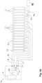
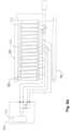
- a first embodiment of a medical air mattress in accordance with the present inventioncomprises a lower bedspread 10, a mattress body 30, an upper bedspread 50 and a guardrail unit (60), with two guardrail sleeves 52 mounted on each longitudinal side of the upper bedspread 50.
- each guardrail sleeve 52comprises two sleeve bodies 521 fixedly stitched with two lines or a double line to the upper bedspread 50.
- Fig. 1Bshows the medical air mattress in perspective view
- Fig. 1Cshows a schematic picture of a medical air mattress with inclination to the right side of the patient 801 lying on the bearing surface 803 of the medical air mattress.
- Each sleeve body 521 of the guardrail according to Fig. 1B and 1Chas a flat base 800 which is fixed to the top cover of the - preferably alternating - air mattress in order to firmly hold the sleeves on the upper bedspread.
- the mounting of the sleeve 52 or the sleeve bodies 521 especially by stitching them to the bedspread 50is such, that causing air leakage in the guardrail air cells 61 and/or the body air cells 31, 32 is avoided, also in case of mechanically stressing or straining the guardrail unit (60), e. g. by the patient 801.
- the safety of the patient 801 and the handling of the mattresswill so be optimized.
- the mattress body 30is mounted on the lower bedspread 10 comprising of multiple body air cells 31 and multiple head air cells 32.
- the mattress body 30comprises three head air cells 32.
- Each body air cell 31 and each head air cell 32are tubular and respectively uniform in diameter.
- the head air cells 32have the same diameter with the body air cells 31.
- the body air cells 31 and the head air cells 32are parallel to each other and are arranged in a row forming an air cell row.
- the head air cells 32are arranged at a head end in the air cell row, i.e. the head air cells 32 arranged at first to third in the air cell row.
- the body air cells 31are arranged at fourth to seventeenth in the air cell row.
- the upper bedspread 50covers the mattress body 30 and is connected securely to the lower bedspread 10.
- a heat unit 51is installed preferably under the upper bedspread 50 and above mattress body 30 for heating.
- the heat unit 51may be a carbon fiber electro thermal sheet.
- the upper bedspread 50has guardrail sleeves 52.
- the guardrail sleeves 52are formed parallel on both longitudinal sides of the upper bedspread 50 and are respectively formed adjacent to the edges of both (longitudinal) sides of the upper bedspread 50.
- the guardrail sleeves 52are stitched on the upper bedspread 50.
- Each guardrail sleeve 52has at least one sleeve body 521.
- each guardrail sleeve 52has two sleeve bodies 521 formed separately and aligning with and coaxial to each other.
- the guardrail air unit 60is mounted in the guardrail sleeves 52 and comprises multiple guardrail air cells 61.
- the guardrail air cells 61are mounted respectively in the sleeve bodies 521 of the guardrail sleeve 52.
- the medical air mattressfurther comprises a massage unit 40 mounted on or in the mattress body 30 (see also Fig. 2A ).
- the massage unit 40according to Fig. 2B comprises multiple vibrator units 806 or micro vibrators 41 respectively in order to massage the patients 801 lying on the bearing surface 803 of the medical air mattress as described. Those micro vibrators 806, 41 distribute massage separately and respectively to patient's neck, back, waist, thighs and so on.
- the massage unit 40may further comprise a first layer 804 and a second layer 805. Each layer 804, 805 can be made of a material, which is waterproof or nearly waterproof. Below the first layer 804 and/or the second layer 805 the second layer 805 multiple vibrator units 806 are positioned.
- Each vibrator unit 806can be placed in a vibrator unit holding bag 807.
- a heating element 51can be placed between both layers 804, 805.
- the heating element 51can comprise a carbon material.
- the heat unit 51can be positioned on or in the mattress body 30 separately, that is to say e. g. without a massage unit 40.
- the medical air mattress as describedcomprises a pumping assembly 70.
- the pumping assembly 70is connected to and selectively inflates the body air cells 31, the head air cells 32 and independent air cells 23.
- the independent air cellscan be conically shaped, so that each independent air cell gradually- tapers in diameter from one end to the other end, so that each body air cell and each independent air cell has a wide end and a narrow end.
- the pumping assembly 70comprises a pump 71, an odd body pipeline 73, an even body pipeline 74, an odd independent pipeline 54, an even independent pipeline 55 and a rapidly releasing valve 78, as shown in Fig. 3A .
- the odd body pipeline 73connects the pump 71 with the odd body air cells 31 and the head air cells 32 at odd rows of the air cell rows.
- An even (odd) rowmeans a row at an even (odd) position of the air cell row.
- the even body pipeline 74connects the pump 71 with the even body air cells 31 and the head air cells 32 at even rows of the air cell rows.
- the odd independent pipeline 54connects the pump 71 with the independent air cells 23 at odd rows of the air cell rows.
- the even independent pipeline 55connects the pump 71 with the independent air cells 23 at even rows of the air cell rows.
- the rapidly releasing valve 78is connected to the odd body pipeline 73 and the even body pipeline 74 for rapidly releasing the air in the mattress body 30 for emergency use.
- C.P.R.cardiopulmonary resuscitation
- the medical air mattress as describedneeds not be removed or the patient needs not be moved since the mattress body 30 is rapidly deflated to rescue the patient immediately. This contributes to the improvement of the handling of the medical air mattress.
- the pump 71is connected to a body alternating-valve 702.
- the body alternating-valve 702is connected between the pump 71 and the body pipelines 73, 74 and the independent pipelines 54, 55.
- the independent air cells 23are connected to an independent deflating unit to be deflated independently.
- the independent deflating unitcomprises an odd solenoid valve 541 and an even solenoid valve 551.
- the odd and even solenoid valves 541, 551are three-way valves and respectively have deflating opening to the exterior so that the independent air cells 23 are selectively deflated independently via the odd and even solenoid- valves 541, 551.
- the odd independent pipeline 54is connected to the pump 71 via the odd body pipeline 73.
- the even independent pipeline 55is connected to the pump 71 via the even body pipeline 74.
- the odd independent pipeline 54is connected to the odd body pipeline 73 via the odd independent solenoid valve 541
- the even independent pipeline 55is connected to the even body pipeline 74 via the even independent solenoid valve 551.
- the odd body pipeline 73is connected to the head air cells 32 via a first check valve 731.
- the even body pipeline 74is connected to the head air cells 32 via a second check valve 741.
- the independent deflating unit for the independent air cells 23may be a manual alternating device 80.
- the usercontrols the manual alternating device 80 to stop inflating the independent air cells 23.
- the manual alternating device 80has an air inlet, an inflating opening, a deflating opening, a linking rod, two airflow washers, an air restricting washer and a resilient element.
- the air inletis connected to the body alternating-valve 702.
- the inflating openingis connected to the independent air cells 23 through the independent pipelines 54, 55.
- the deflating openingcommunicates with the exterior. When inflating, the deflating opening is closed and the inflating opening is opened to inflate the independent air cells 23.
- the resilient element, the linking rod and the air restricting washerare manually moved to close the inflating opening and to open the deflating opening. Then the independent air cells 23 are deflated independently.
- sanitation aspects of the medical air mattressbecome improved, so that the air mattress can be better handled. It is no longer necessary to remove the top cover of the mattress in order to get access to a removable part of the mattress, e. g. like it can be seen in the state of the art according to Fig. 11A .
- the medical air mattress as describedcomprises a pumping assembly 70.
- the pumping assembly 70is connected to and selectively inflates the inclination providing air cells 20, the body air cells 31, the head air cells 32 and the guardrail air cells 61.
- the pumping assembly 70comprises a pump 71, an inclination providing pipeline 72, an odd body pipeline 73, an even body pipeline 74, a guardrail pipeline 77 and a rapidly releasing valve 78.
- the inclination providing pipeline 72connects the pump 71 with the inclination pro- viding air cells 20.
- the odd body pipeline 73connects the pump 71 with the body air cells 31 and the head air cells 32 at odd positions of the air cell rows.
- the even body pipeline 74connects the pump 71 with the body air cells 31 and the head air cells 32 at even positions of the air cell rows.
- the guardrail pipeline 77connects the pump 71 with the guardrail air cells 61.
- the rapidly releasing valve 78is connected to the odd body pipeline 73 and the even body pipeline 74 for rapidly releasing the air in the mattress body 30 for emergency uses. For example, when the patient needs C.P.R., the medical air mattress and the guard rail assembly as described needs not be removed or the patient needs not be moved since the mattress body 30 and the guardrail assembly is rapidly deflated to rescue the patient immediately.
- the pump 71is connected to an inclination providing alternating-valve 701 and a body alternating-valve 702.
- An inclination providing solenoid valve 703is also connected between the inclination providing alternating-valve 701 and the pump 71.
- the inclination providing alternating-valve 701is connected between the inclination providing solenoid valve 703 and the inclination providing pipeline 72.
- the body alternating-valve 702is connected between the pump 71 with the body pipelines 73, 74 and the guardrail pipeline 77.
- the guardrail pipeline 77is connected to the body alternating-valve 702 via a guardrail solenoid valve 772.
- the odd body pipeline 73is connected to the head air cells 32 via a check valve 731.
- the even body pipeline 74is connected to the head air cells 32 via a check valve 741.
- the body alternating-valve 702is connected to the guardrail solenoid valve 772 via a check valve 771.
- the deflating unit for the guardrail air cells 61may be a manual alternating device 772A.
- the usercontrols the manual alternating device 772A to stop inflating the guardrail air cells 61.
- the manual alternating device 772Ahas an air inlet, an inflating opening, a deflating opening, a linking rod, one or more airflow washers, an air restricting washer and a resilient element.
- the air inletis connected to the body alternating-valve 702.
- the inflating openingis connected to the guardrail air cells 61 through the guardrail pipeline 77.
- the deflating openingcommunicates with the exterior. When inflating, the deflating opening is closed and the inflating opening is opened to inflate the guardrail air cells 61.
- the resilient element, the linking rod and the air-resisting washerare manually moved to close the inflating opening and to open the deflating opening. Then the guardrail air cells 61 are deflated independently.
- the pump 71, the alternating-valves 702 and the solenoid valves 541, 551are actuated to inflate the air cells and to alternatively adjust the inflating.
- the inflating and the deflating operationsare described detailed below.
- Alternating inflating modeWith reference to Figs. 3A and 38, the pump 71 is operated and inflates the body air cells 31 and the independent air cells 23 at odd or even rows of the air cell rows alternatively.
- the body alternating-valve 702accomplishes the alternating inflating.
- the pump 71supplies air into the body alternating-valve 702.
- the body alternating-valve 702alternatively supplies air into the odd or even body pipelines 73, 74.
- the odd body pipeline 73is inflated, the body air cells 31 and the independent air cells 23 at odd rows of the air cell rows are in-flated and the body air cells 31 and the independent air cells 23 at even rows of the air cell rows are deflated as shown in Fig. 5 .
- the body air cells 31 and the independent air cells 23 at even positions of the air cell rowsare inflated and the body air cells 31 and the independent air cells 23 at odd positions of the air cell rows are deflated as shown in Fig. 6 .
- the check valves 731, 741are connected between the head air cells 32, the odd and even body pipelines 73, 74, the head air cells 32 are kept inflated without deflating by the body alternating-valve 702 to support the patient's head stably.
- the usermay stop inflating the independent air cells 23 independently.
- the odd solenoid valve 541 and the even solenoid valve 551are used to stop inflating the independent air cells 23.
- Each solenoid valve 541, 551has an air inlet, an inflat- ing opening and a deflating opening.
- the air inletis connected to the body alternat- ing-valve 702.
- the inflating openingis connected to the independent air cells 23 through the independent pipelines 54, 55.
- the deflating openingis connected to the exterior. When the independent air cells 23 are inflated, the deflating opening is closed and the inflating opening is opened.
- the inflating openingis closed and the deflating opening is opened.
- the central part of the upper bedspread 50 corresponding to the inde- pendent air cells 23is not supported when the independent air cells 23 are deflated. If required the central part of the upper bedspread 50 can be recessed to form space or place for receiving the bedpan. Therefore, the patient 801 lying on the bearing surface 803 of the medical air mattress as described does not have to move and can use the bedpan while lying on the medical air mattress as described.
- the pump 71, the alternating-valves and the solenoid valvesare actuated to inflate the air cells and to adjust the inflating.
- the inflating and the deflating operationsare described detailed below.
- guardrail air cells 61when the pump 71 is operated, the guardrail air cells 61 are inflated to expand the guardrail sleeves 52 to provide side protections on the upper bedspread 50.
- the guardrail sleeves 52 on both sidesare drawn by each other since the guardrail sleeves 52 are formed on both sides of the upper bedspread 50.
- the drawing forcekeeps the guardrail sleeves 52 maintaining their shapes even being pressed. Therefore, the guardrail sleeves 52 are kept in position to protect the patients lying on the medical air mattress as described.
- the check valve 771keeps the air from back flowing when the body alternating-valve 702 is operated.
- the pump 71is operated and inflates the body air cells 31 at odd or even rows of the air cell rows alternately.
- the body alternating-valve 702accomplishes the alternating inflating.
- the pump 71supplies air into the body alternating-valve 702.
- the body alternating-valve 702alternately supplies air into odd or even body pipelines 73, 74.
- the odd body pipeline 73is inflated, the body air cells 31 at odd positions of the air cell rows are inflated and the body air cells 31 at even positions of the air cell rows are deflated as shown in Fig. 5 .
- the body air cells 31 at even rows of the air cell rowsare inflated and the body air cells 31 at odd rows of the air cell rows are deflated as shown in Fig. 6 .
- the check valves 731, 741are connected between the head air cells 32 with the odd and even body pipelines 73, 74, the head air cells 32 are kept inflated without deflating by the body alternating-valve 702 to support the patient's head stably.
- the pump 71is operated to inflate one of the inclination providing air cells 20 to tilt one side of the medical air mattress as described so that the patient is to be turned over easily.
- the inclination providing alternating-valve 701is operated to inflate the inclination providing air cells 20 alternately.
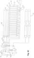
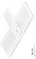
- the body air cells 31A of the body mattress 30A according to Fig. 8are conical.
- An end view of the air mattress with conical mattress bodiesis shown in Fig. 7A and 78.
- Each body air cell 31Agradually tapers in diameter from one end to the other end so that each body air cell 31A has a wide end and a narrow end.
- the body air cells 31Aare arranged with wide ends adjacent to the narrow ends. For example, the wide ends of the body air cells 31A at odd positions of the air cell rows align with the narrow ends of the body air cells 31A at even positions of the air cell rows.
- the medical air mattress as describedfurther comprises two offset air cells 34A mounted longitudinally and mounted respectively on two sides of the mattress body 30A to enlarge the area of the medical air mattress and to support the upper bedspread 50A.
- the offset air cells 34Aare connected to the pipeline connecting to the head air cells 32A and are also protected by the check valves 731, 741 to maintain inflating.
- the pump 71A, the alternating-valves and the solenoid valvesare also actuated to inflate the air cells and to alternatively adjust the inflating. Since most operations are discussed above, only different operations are described below for the embodiment of the medical air mattress according to Fig. 8 .
- the pump 71Awhen the pump 71A is operated, user may select different modes.
- the pump 71Ais operated to inflate all the body air cells 31A and the head air cells 32A.
- the pump 71Ais operated and inflates the body air cells 31A at odd or even rows of the air cell rows alternatively.
- the body air cells 31A at odd rows of the air cell rowsare inflated, the body air cells 31A at even rows of the air cell rows are deflated as shown in Fig. 10A . Since the body air cells 31A at odd positions of the air cell rows have wide left ends and narrow right ends, the mattress body 30A is higher at left side and lower at right side to tilt the patient rightward.
- the body air cells 31A at even rows of the air cell rowsare inflated, the body air cells 31A at odd rows of the air cell rows are deflated as shown in Fig. 1OB . Since the body air cells 31A at even positions of the air cell rows have wide right ends and narrow left ends, the mattress body 30A is higher at right side and lower at left side to tilt the patient leftward. Therefore, the alternating inflating of the body air cells 31A not only provides the alternative wave of the mattress body 30A, but also tilts the patient at certain inclination angle. In this embodiment, the body air cells 31A provides inclination angle at, said 10 degrees or nearly 10 degrees. "Nearly" in this connection means, that the inclination angle may be a few degrees smaller or larger than the given angle.
- the alternating inflating of the body air cells 31A associated with the inclination providing air cells 20Aprovides more different inclination angles.
- the inclination providing air cell 20A at right sideis also simultaneously inflated to provide a totally added inclination angle at, said 30 degrees or nearly 30 degrees.
- the inclination providing air cell 20A at left sideis also inflated to provide an inclination angle at, said 30 degrees or nearly 30 degrees.
- FIG. 1OFAn overview about the inclination conditions of the aforementioned medical air mattress and the possibility of inclining or rotating the patient with multiple angles is shown in Fig. 1OF .
- the figure parts of Fig. 1OFare related to a method to inflate/deflate a medical air mattress as described above.
- the air cellsare inflated and/or deflated selectively.
- the even and/or odd air cellsare inflated and/or deflated separately, such that either all even or all odd air cells are inflated or deflated, or such that all even and odd air cells are inflated.
- At least three inclination anglesare achievable by selectively inflating and/or deflating inclination providing air cells and/or even body cells and/or odd body cells and/or even and odd body cells.
- either the even or the odd body air cells 32are inflated.
- the inclination providing air cells 20are both deflated. In this condition the surface is inclined in a first small angle, e. g. 10 degree or nearly 10 degree.
- the inclination providing air cells (20, 20A)are inflated either on the right or on the left side of the mattress body (30, 30A). Both, the even and the odd body air cells (31, 31A, 32, 32A, 23, 23A) are also inflated, so that the inclination angle according to figure part (c) and (d) is larger than it is the case in figure parts (a) and (b), e. g. nearly 20 degrees.
- the even or the odd body air cells (31, 31A, 32, 32A, 23, 23A)are inflated and one of the inclination providing air cell (20, 20A) is also inflated simultaneously. So the total inclination angle becomes even larger, e. g. nearly 30 degrees.
- All of the conditions of the medical air mattresscan be controlled by a control device shown in Fig. 12 and 12B .
- the control deviceis connected to the pumping assembly and to all valves of the medical air mattress, e. g. shown in Fig. 3A to 30, 9A and 9B.
- Most of the conditionscan be handled with a one touch-operation of the control device.
- the inflation/deflation of the guardrail, of the cells which are engaged when inclining the mattress, or of independent air cells in order to provide a center portion of the mattress with a space to receive a container like a bedpancan be controlled with one-hand- or one touch-operation of the control device. All these functions and conditions can be operated by pressing only one button of the control device.
- the medical air mattress in accordance with the present inventionhas numerous advantages. With the guardrail sleeves 52 formed on the top of the upper bedspread 50, the mutual drawing-force between the guardrail sleeves 52 from two opposite sides of the upper bedspread 50 holds the guardrail sleeves 52 in position to protect the patient 801 lying on the medical air mattress. Furthermore, the body air cells 31A in conical shape associated with the inclination providing air cells 20A provide multiple inclination angles. Therefore, different patients may choose a proper inclination angle they need or as instructed by the doctor.
- a heat unit 51is attached in the mattress body. Preferably it is positioned under the upper bedspread 50 for heating the upper bedspread.
- the heat unit 51may be a carbon fiber electro thermal sheet.
- the heat unit 51can be a component or in integral part of a heat-and-massage unit show in Fig. 2B .
- FIG. 11BA medical air mattress with independent air cells 23 is shown in Fig. 11B .
- Fig. 11Ba side view of the air mattress is shown.
- the body air cells 31 and the head air cells 32are inflated.
- the independent air cells 23are deflated, so that in the center region of the mattress body 30 a position for receiving a container like a toilet or a bedpan is generated.
- the position for receiving the containercan have a nearly conical shape.
- Inflation or deflation of the independent air cells 23can be controlled with the controller according to Fig. 12A /B.
- By generating a concave position for receiving the bedpanit is no longer necessary to e. g. remove a part of the mattress body according to the state of the art (see Fig. 11A ).
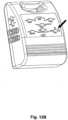
- the controller of the medical air mattressis constructed in a way that several functions of the air mattress can be controlled by touching only one button.
- the inflation/deflation of the guardrail unitcan be controlled with a one-touch-button for the guardrail-function ( Fig. 12A , see arrow).
- One-touch-buttonmeans that touching the button once enables or disables the related function of the mattress.
- the inflation/deflation of the independent air cells 23can be controlled with a one-touch-button of the toilet function.
- the inclination of the mattress surface at different anglescan be controlled with a one touch-button for the inclination function (pitch, see arrow Fig. 128).
- Touching the "pitch"-buttonincreases or decreases the angle of the mattress surface according to the method described above.
- the alternating of the inflation of the (body and/or head) air cellscan be controlled with a one-touch-button for the static/alternation function.
- the heating of the mattresscan be controlled with a one-touch-button for the heater-function.
- the massage unit of the mattresscan be controlled with a one-touch-button of the massage function.
- the controller according to Figs. 12A / 8can be positioned near the mattress body so that it can be operated by the medical staff or the patient himself.
Landscapes
- Health & Medical Sciences (AREA)
- Nursing (AREA)
- Life Sciences & Earth Sciences (AREA)
- Animal Behavior & Ethology (AREA)
- General Health & Medical Sciences (AREA)
- Public Health (AREA)
- Veterinary Medicine (AREA)
- Invalid Beds And Related Equipment (AREA)
- Mattresses And Other Support Structures For Chairs And Beds (AREA)
Description
- The present invention is related to a medical air mattress according to the claims, especially to a medical air mattress for anti- decubitus purposes. Thus the medical air mattress comprises a lower bedspread and a mattress body mounted on the lower bedspread. The mattress body comprises multiple body air cells substantially parallel to each other arranged in a row forming an air cell row. The mattress can additionally comprise head air cells, wherein the head air cells are arranged at a head end in the air cell row. The mattress further comprises an upper bedspread covering the mattress body and connected securely to the lower bedspread. It further comprises a pumping assembly with a pump and at least a pipeline connecting the pump with the air cells.
- The invention is further related to a method for inflating and/or deflating a generic medical air mattress, to a method to incline the surface of a medical air mattress and to a method to generate in medical air mattress a position for receiving a container according to the claims.
- Patients who have physical difficulties with mobility or bedfast mostly lie on a mattress over a long period of time and are thus susceptible to develop decubitus ulcers on multiple areas of body due to continuous pressure. In order to minimize or eliminate the development of decubitus ulcers caretakers must turn patients' body over or move patient to alternate the areas of pressure on the body. The conventional medical air mattress was developed to assist in the manual movement of and alternating pressure areas on the patient to generate wave motion for changing the contact areas of the patient's body. The conventional medical air mattress has the following inadequacies.
- To assist patients in turning over, two inclination providing cells are mounted under the body air cells. When the patients need to turn over, one of the inclination providing cells inflates to tilt the conventional air mattress. This design offers only one inclination angle. Patients with varying disabilities will require different inclination positions, which are decided by physicians or the patient's discomfort. In the event that the patient requires a different angle than that offered by the conventional air mattress caretakers may use non-recommended accessories or the therapy cannot be provided. Either of these options put the patient at risk of injury.
- Because the patients lying on the conventional air mattress have difficulty with mobility or bedfast, the protective apparatus around the conventional air mattress is important to keep the patient from falling off of the mattress. Hospital beds, which a medical mattress is used on, are equipped with guardrails, which at times can prohibit medical staff from taking care of the patients lying on the hospital beds and cannot always be in optimal position for patient protection. Many patients require the continued therapy of a medical air mattress in their homes. The medical air mat -tress is also required to assist caretakers moving the patient with minimal manual labor. In many cases the home is not equipped with guardrails on the bed that the medical air mattress is being used. The conventional medical air mattress can have air filled guardrails to protect patients and to assist caretakers, who can easily press down the air guardrails.
US 5611096 (D1) is the closest prior art and describes an air bed with inflatable parts. There is no teaching or suggestion in this document of the feature of the invention to form a guardrail sleeve which is fixed to the bedspread cover. If the patient accidentally compresses either air guardrail, such air guardrails will slant outward and cannot protect the patient anymore, causing the opportunity for the patient to fall from mattress. Such air guardrails have no connection with the upper bedspreads, only being connected to the lower bedspreads restrict the ability to have mutual-drawing power to each other from two- side on the upper bedspreads. - Further difficulties with handling a conventional air mattress occur when the patients lying on the mattress need to use a bedpan. The conventional air mattress has several detachable air cells, which correspond to the position of the patient's hip. A mattress according to the state of the art is presented in
Fig. 11 A , which is described more detailed later. When the detachable air cells are removed to form a recess, the bedpan will be able to be put into the recess for use. However, to prevent secondary infection and to be cleaned with ease, the conventional air mattress has an upper bedspread to cover on the air cells. Therefore, the upper bedspread needs to be removed before the detachable air cells are removed. Removing the upper bedspread still requires the need to move the patient lying on the conventional air mattress. The design of detachable air cells is inconvenient to caretakers since the patient still needs to leave the conventional air mattress. Furthermore moving the patient and removing the upper bedspread requires two or more individuals. This is an inefficient use of time and human resources, and the detachable air cells do not function as what the original design expected. - It is an object of the present invention to provide a medical air mattress with improved handling, improved possibilities to assist movement of the patient and to mitigate or obviate the aforementioned inadequacies.
- This problem is solved by a medical air mattress according to the claims. Thus the pipeline connected to the pump and/or to the air cells is adapted to control inflating and/or deflating of the air cells selectively. With respect to this selectively means, that a chosen air cell or a group of chosen air cells can be inflated and/or deflated independently without inflating and/or deflating the rest of the air cells, that is to say without inflating and/or deflating one or more not chosen air cells.
- . Preferred embodiments of the invention are presented in the sub claims.
- In order to generate movement in the bearing surface of the medical air mattress and in order to incline the surface of the mattress it is suggested to provide the medical air mattress with an odd body pipeline connecting the pump with the air cells at odd positions of the air cell row and with an even body pipeline connecting the pump with the air cells at even positions of the air cell row.
- In order to improve the handling of a medical air mattress it is suggested to deflate some or all components of the medical air mattress according the invention in a very quick way - e. g. in case of an medical emergency - by a rapidly releasing valve. It can be connected to the pipeline, preferably to the odd body pipeline and the even body pipeline.
- In order to provide a multiple inclination mode of the medical air mattress according to the invention additional inclination providing air cells are provided. The inclination providing air cells are mounted longitudinally on the lower bedspread, preferably such that the mattress body is mounted across the inclination providing air cells, near two longitudinal sides of the lower bedspread, and substantially parallel to each other. Thus the inclination of the surface of the mattress in order to move the patient can (additionally) be modified by inflating/deflating the inclination providing air cells independently, that is to say without inflating and/or deflating other air cells of the mattress.
- According to a further aspect of the invention each air cell is gradually tapered in diameter from a wide end to a narrow end. The air cells are arranged with wide ends adjacent to the narrow ends. This on the one hand improves the anti decubitus performance of the medical air mattress so that it can be handled in a more simple way. On the other hand by inflating and/or deflating the gradually tapered body air cells selectively the surface of the mattress can be inclined.
- According to a further aspect of the invention a guardrail with guardrail air cells and a guardrail pipeline are provided. The guardrail pipeline connects the pump with the guardrail air cells. By providing a medical air mattress with an inflatable/deflatable guardrail assembly injuries of the patient can be avoided. Moreover the handling of the guardrail is simplified by the medical air mattress according to the invention, because it can be removed by deflating the guardrail air cells independently. Bringing the guardrail in its guarding position can be done by inflating the guardrail air cells.
- In order to further improve the handling of the medical air mattress it is suggested to provide mutual-drawing guardrail sleeves to keep the guardrail sleeves from tilting when being pressed. The medical air mattress can additionally have guardrail unit. The upper bedspread covering the mattress body has at least a guardrail sleeve fixed on at least one side of the upper bedspread. The guardrail unit can have multiple guardrail air cells mounted respectively in guardrail sleeves. The guardrail sleeves are formed on the upper bedspread, the upper bedspread and the guardrail sleeves will draw each other on two-side to ensure the guardrail sleeves remain in position when pressed. Therefore, the guardrail sleeves will not fall down when pressed and continue to provide optimal protection for the patient as its intended purpose.
- Further improvement of the anti decubitus performance of the mattress is achieved by providing a massage unit mounted on the mattress body, preferably having multiple micro vibrators. Alternatively or additionally the medical air mattress according to the invention can be equipped with a heat unit in form of an electro thermal sheet.
- In order to further simplify the handling of the mattress and specially to generate a position for receiving a bedpan or any other kind of container without significantly moving the patient independent air cells can be arranged at a central part in the air cell row. The independent air cells can be connected to the pumping assembly. According to this aspect of the invention the mattress body is formed by multiple air cells including independent air cells parallel arranged as an air cell row. The independent air cells can be connected to the independent deflating unit to be deflated independently. When the patient needs to use the bedpan, the independent air cells are deflated to form a recess for receiving the bedpan so that the bedspread and the patient have no need to be moved.
- Other objectives, advantages and novel features of the invention will become more apparent from the following detailed description, when reviewed in conjunction with the accompanying drawing.
- The invention is defined by the claims. Embodiments partly not falling under the scope of the claims, partly describing the claimed subject-matter are listed in the following.
- Additional details, characteristics and advantages of the invention result from the sub claims and appear in the description and the associated drawings in which, for the sake of example, several embodiments and examples according to the invention as claimed and further more not falling under the scope of the claims for highlighting specific aspects of the subject-matter of the disclosure are illustrated. Shown in the drawing are:
- Fig. 1A
- a perspective view of a medical air mattress in accordance with the present invention;
- Fig. 18
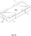
- a perspective view of a medical air mattress with guardrail sleeves comprising a flat base connected to the upper bedspread;
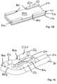
- Fig. 1C
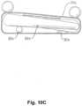
- a perspective view of a medical air mattress, the surface of the mattress being inclined on one longitudinal side of the mattress body;
- Fig. 2A
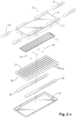
- an exploded perspective view of the medical air mattress according to
Fig. 1 ; - Fig. 28
- an exploded perspective view of a massage and heater unit of the medical air mattress according to
Fig. 2A ; - Fig. 3A-D
- pipeline diagrams of different embodiments of the medical air mattress;
- Fig. 4
- an operational side view in partial section of the medical air mattress in
Fig. 1 , showing the body air cells all inflated; - Fig. 5
- an operational side view in partial section of a medical air mattress, showing the odd body air cells inflated;
- Fig. 6
- an operational side view in partial section of a medical air mattress, showing the even body air cells inflated;
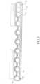
- Fig. 7A/B
- an operational end view in partial section of a different embodiment of the medical air mattress, showing a body air cell being gradually tapered in diameter from a wide end to a narrow end;
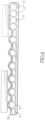
- Fig. 7C
- an operational end view in partial section of a different embodiment of the medical air mattress with two inclination providing air cells, one of them being inflated;
- Fig. 8
- an exploded perspective view of another embodiment of a medical air mattress;
- Fig. 9A/B
- a pipeline diagram of different embodiments of the medical air mattress;
- Fig. 1OA-E
- an operational end view in partial section of the medical air mattress, showing different air cells inflated;
- Fig. 1OF
- a scheme of 6 operational end views in partial section of an embodiment of the air mattress, showing different inclination angles ((a) - (f));
- Fig. 11A
- a perspective view a medical air mattress with a removable center portion according to the state of the art;
- Fig. 11B an
- operational side view in partial section of the medical air mattress according to the invention, showing deflated independent air cells in a center region of the mattress body; and
- Fig. 12A/B
- perspective views of a control device of the medical air mattress according to the invention.
- With reference to
Figs. 1A , a first embodiment of a medical air mattress in accordance with the present invention comprises alower bedspread 10, amattress body 30, anupper bedspread 50 and a guardrail unit (60), with twoguardrail sleeves 52 mounted on each longitudinal side of theupper bedspread 50. According toFig. 1B and 1C eachguardrail sleeve 52 comprises twosleeve bodies 521 fixedly stitched with two lines or a double line to theupper bedspread 50.Fig. 1B shows the medical air mattress in perspective view andFig. 1C shows a schematic picture of a medical air mattress with inclination to the right side of thepatient 801 lying on thebearing surface 803 of the medical air mattress. - Each
sleeve body 521 of the guardrail according toFig. 1B and 1C has aflat base 800 which is fixed to the top cover of the - preferably alternating - air mattress in order to firmly hold the sleeves on the upper bedspread. The mounting of thesleeve 52 or thesleeve bodies 521 especially by stitching them to thebedspread 50 is such, that causing air leakage in theguardrail air cells 61 and/or thebody air cells patient 801. The safety of thepatient 801 and the handling of the mattress will so be optimized. - According to
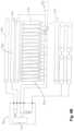
Fig. 2A themattress body 30 is mounted on thelower bedspread 10 comprising of multiplebody air cells 31 and multiplehead air cells 32. In a preferred embodiment, themattress body 30 comprises threehead air cells 32. Eachbody air cell 31 and eachhead air cell 32 are tubular and respectively uniform in diameter. Thehead air cells 32 have the same diameter with thebody air cells 31. Thebody air cells 31 and thehead air cells 32 are parallel to each other and are arranged in a row forming an air cell row. Thehead air cells 32 are arranged at a head end in the air cell row, i.e. thehead air cells 32 arranged at first to third in the air cell row. Thebody air cells 31 are arranged at fourth to seventeenth in the air cell row. - The
upper bedspread 50 covers themattress body 30 and is connected securely to thelower bedspread 10. Aheat unit 51 is installed preferably under theupper bedspread 50 and abovemattress body 30 for heating. Theheat unit 51 may be a carbon fiber electro thermal sheet. Theupper bedspread 50 hasguardrail sleeves 52. Theguardrail sleeves 52 are formed parallel on both longitudinal sides of theupper bedspread 50 and are respectively formed adjacent to the edges of both (longitudinal) sides of theupper bedspread 50. In a preferred embodiment, theguardrail sleeves 52 are stitched on theupper bedspread 50. Eachguardrail sleeve 52 has at least onesleeve body 521. In a preferred embodiment, eachguardrail sleeve 52 has twosleeve bodies 521 formed separately and aligning with and coaxial to each other. - Further referring to
Fig. 2A theguardrail air unit 60 is mounted in theguardrail sleeves 52 and comprises multipleguardrail air cells 61. Theguardrail air cells 61 are mounted respectively in thesleeve bodies 521 of theguardrail sleeve 52. - According to
Fig. 2B the medical air mattress further comprises amassage unit 40 mounted on or in the mattress body 30 (see alsoFig. 2A ). Themassage unit 40 according toFig. 2B comprisesmultiple vibrator units 806 ormicro vibrators 41 respectively in order to massage thepatients 801 lying on thebearing surface 803 of the medical air mattress as described. Thosemicro vibrators massage unit 40 may further comprise afirst layer 804 and asecond layer 805. Eachlayer first layer 804 and/or thesecond layer 805 thesecond layer 805multiple vibrator units 806 are positioned. Eachvibrator unit 806 can be placed in a vibratorunit holding bag 807. In or above the massage unit aheating element 51 can be placed between bothlayers heating element 51 can comprise a carbon material. Alternatively theheat unit 51 can be positioned on or in themattress body 30 separately, that is to say e.
g. without amassage unit 40. - With reference to
Fig. 3A , the medical air mattress as described comprises a pumpingassembly 70. The pumpingassembly 70 is connected to and selectively inflates thebody air cells 31, thehead air cells 32 andindependent air cells 23. With reference toFig. 9A the independent air cells can be conically shaped, so that each independent air cell gradually- tapers in diameter from one end to the other end, so that each body air cell and each independent air cell has a wide end and a narrow end. - Preferably the pumping
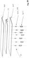
assembly 70 comprises apump 71, anodd body pipeline 73, aneven body pipeline 74, an oddindependent pipeline 54, an evenindependent pipeline 55 and a rapidly releasingvalve 78, as shown inFig. 3A . Theodd body pipeline 73 connects thepump 71 with the oddbody air cells 31 and thehead air cells 32 at odd rows of the air cell rows. An even (odd) row means a row at an even (odd) position of the air cell row. Theeven body pipeline 74 connects thepump 71 with the evenbody air cells 31 and thehead air cells 32 at even rows of the air cell rows. The oddindependent pipeline 54 connects thepump 71 with theindependent air cells 23 at odd rows of the air cell rows. The evenindependent pipeline 55 connects thepump 71 with theindependent air cells 23 at even rows of the air cell rows. The rapidly releasingvalve 78 is connected to theodd body pipeline 73 and theeven body pipeline 74 for rapidly releasing the air in themattress body 30 for emergency use. For example, when the patient needs cardiopulmonary resuscitation (C.P.R.), the medical air mattress as described needs not be removed or the patient needs not be moved since themattress body 30 is rapidly deflated to rescue the patient immediately. This contributes to the improvement of the handling of the medical air mattress. - According to
Fig. 3A thepump 71 is connected to a body alternating-valve 702. The body alternating-valve 702 is connected between thepump 71 and thebody pipelines independent pipelines independent air cells 23 are connected to an independent deflating unit to be deflated independently. The independent deflating unit comprises anodd solenoid valve 541 and aneven solenoid valve 551. The odd and even solenoidvalves independent air cells 23 are selectively deflated independently via the odd and even solenoid-valves independent pipeline 54 is connected to thepump 71 via theodd body pipeline 73. The evenindependent pipeline 55 is connected to thepump 71 via theeven body pipeline 74. In a preferred embodiment, the oddindependent pipeline 54 is connected to theodd body pipeline 73 via the oddindependent solenoid valve 541, and the evenindependent pipeline 55 is connected to theeven body pipeline 74 via the evenindependent solenoid valve 551. Theodd body pipeline 73 is connected to thehead air cells 32 via afirst check valve 731. Theeven body pipeline 74 is connected to thehead air cells 32 via asecond check valve 741. - With reference to Fig. 38, the independent deflating unit for the
independent air cells 23 may be a manual alternatingdevice 80. The user controls the manual alternatingdevice 80 to stop inflating theindependent air cells 23. The manual alternatingdevice 80 has an air inlet, an inflating opening, a deflating opening, a linking rod, two airflow washers, an air restricting washer and a resilient element. The air inlet is connected to the body alternating-valve 702. The inflating opening is connected to theindependent air cells 23 through theindependent pipelines independent air cells 23. When deflating, the resilient element, the linking rod and the air restricting washer are manually moved to close the inflating opening and to open the deflating opening. Then theindependent air cells 23 are deflated independently. - Thus according to the invention sanitation aspects of the medical air mattress become improved, so that the air mattress can be better handled. It is no longer necessary to remove the top cover of the mattress in order to get access to a removable part of the mattress, e. g. like it can be seen in the state of the art according to
Fig. 11A . - With reference to
Fig. 3C , the medical air mattress as described comprises a pumpingassembly 70. The pumpingassembly 70 is connected to and selectively inflates the inclination providingair cells 20, thebody air cells 31, thehead air cells 32 and theguardrail air cells 61. The pumpingassembly 70 comprises apump 71, aninclination providing pipeline 72, anodd body pipeline 73, aneven body pipeline 74, aguardrail pipeline 77 and a rapidly releasingvalve 78. Theinclination providing pipeline 72 connects thepump 71 with the inclination pro- vidingair cells 20. Theodd body pipeline 73 connects thepump 71 with thebody air cells 31 and thehead air cells 32 at odd positions of the air cell rows. Theeven body pipeline 74 connects thepump 71 with thebody air cells 31 and thehead air cells 32 at even positions of the air cell rows. Theguardrail pipeline 77 connects thepump 71 with theguardrail air cells 61. The rapidly releasingvalve 78 is connected to theodd body pipeline 73 and theeven body pipeline 74 for rapidly releasing the air in themattress body 30 for emergency uses. For example, when the patient needs C.P.R., the medical air mattress and the guard rail assembly as described needs not be removed or the patient needs not be moved since themattress body 30 and the guardrail assembly is rapidly deflated to rescue the patient immediately. - According to
Fig. 3C thepump 71 is connected to an inclination providing alternating-valve 701 and a body alternating-valve 702. An inclination providingsolenoid valve 703 is also connected between the inclination providing alternating-valve 701 and thepump 71. The inclination providing alternating-valve 701 is connected between the inclination providingsolenoid valve 703 and theinclination providing pipeline 72. The body alternating-valve 702 is connected between thepump 71 with thebody pipelines guardrail pipeline 77. Theguardrail pipeline 77 is connected to the body alternating-valve 702 via aguardrail solenoid valve 772. Theodd body pipeline 73 is connected to thehead air cells 32 via acheck valve 731. Theeven body pipeline 74 is connected to thehead air cells 32 via acheck valve 741. The body alternating-valve 702 is connected to theguardrail solenoid valve 772 via acheck valve 771. - With reference to
Fig. 3D , the deflating unit for theguardrail air cells 61 may be a manual alternatingdevice 772A. The user controls the manual alternatingdevice 772A to stop inflating theguardrail air cells 61. The manual alternatingdevice 772A has an air inlet, an inflating opening, a deflating opening, a linking rod, one or more airflow washers, an air restricting washer and a resilient element. The air inlet is connected to the body alternating-valve 702. The inflating opening is connected to theguardrail air cells 61 through theguardrail pipeline 77. The deflating opening communicates with the exterior. When inflating, the deflating opening is closed and the inflating opening is opened to inflate theguardrail air cells 61. When deflating, the resilient element, the linking rod and the air-resisting washer are manually moved to close the inflating opening and to open the deflating opening. Then theguardrail air cells 61 are deflated independently. - When the medical air mattress as described in
Fig. 3A and 38 is operated, thepump 71, the alternating-valves 702 and thesolenoid valves - For the mattress body according to
Fig. 3A and 38, when thepump 71 is operated, user may select different modes. - Full inflating mode: With reference to
Figs. 3A and 38, thepump 71 is operated to inflate thebody air cells 31, thehead air cells 32 and theindependent air cells 23. - Alternating inflating mode: With reference to
Figs. 3A and 38, thepump 71 is operated and inflates thebody air cells 31 and theindependent air cells 23 at odd or even rows of the air cell rows alternatively. The body alternating-valve 702 accomplishes the alternating inflating. Thepump 71 supplies air into the body alternating-valve 702. The body alternating-valve 702 alternatively supplies air into the odd or evenbody pipelines odd body pipeline 73 is inflated, thebody air cells 31 and theindependent air cells 23 at odd rows of the air cell rows are in-flated and thebody air cells 31 and theindependent air cells 23 at even rows of the air cell rows are deflated as shown inFig. 5 . When theeven body pipeline 74 is in-flated, thebody air cells 31 and theindependent air cells 23 at even positions of the air cell rows are inflated and thebody air cells 31 and theindependent air cells 23 at odd positions of the air cell rows are deflated as shown inFig. 6 . Moreover, since thecheck valves head air cells 32, the odd and evenbody pipelines head air cells 32 are kept inflated without deflating by the body alternating-valve 702 to support the patient's head stably. - For the
independent air cells 23 as shown inFigs. 3A and 38, the user may stop inflating theindependent air cells 23 independently. Theodd solenoid valve 541 and theeven solenoid valve 551 are used to stop inflating theindependent air cells 23. Eachsolenoid valve valve 702. The inflating opening is connected to theindependent air cells 23 through theindependent pipelines independent air cells 23 are inflated, the deflating opening is closed and the inflating opening is opened. When theindependent air cells 23 are deflated independently, the inflating opening is closed and the deflating opening is opened. The central part of theupper bedspread 50 corresponding to the inde-pendent air cells 23 is not supported when theindependent air cells 23 are deflated. If required the central part of theupper bedspread 50 can be recessed to form space or place for receiving the bedpan. Therefore, thepatient 801 lying on thebearing surface 803 of the medical air mattress as described does not have to move and can use the bedpan while lying on the medical air mattress as described. - When the medical air mattress as described in
Fig. 3C and 30 is operated, thepump 71, the alternating-valves and the solenoid valves are actuated to inflate the air cells and to adjust the inflating. The inflating and the deflating operations are described detailed below. - For
guardrail air cells 61, when thepump 71 is operated, theguardrail air cells 61 are inflated to expand theguardrail sleeves 52 to provide side protections on theupper bedspread 50. When thepatients 801 lying on theupper bedspread 50 accidentally press on theguardrail sleeves 52, theguardrail sleeves 52 on both sides are drawn by each other since theguardrail sleeves 52 are formed on both sides of theupper bedspread 50. The drawing force keeps theguardrail sleeves 52 maintaining their shapes even being pressed. Therefore, theguardrail sleeves 52 are kept in position to protect the patients lying on the medical air mattress as described. Further, thecheck valve 771 keeps the air from back flowing when the body alternating-valve 702 is operated. - For the mattress body according to the embodiment shown in
Fig. 3C and3D , when thepump 71 is operated, user may select different modes. - Full inflating mode: With reference to
Figs. 3C and3D , thepump 71 is operated to inflate thebody air cells 31 and thehead air cells 32. The condition where all air cells of the mattress body are inflated is shown inFig. 4 . - Alternating inflating mode: With reference to
Figs. 3C and3D , thepump 71 is operated and inflates thebody air cells 31 at odd or even rows of the air cell rows alternately. In a preferred embodiment, the body alternating-valve 702 accomplishes the alternating inflating. Thepump 71 supplies air into the body alternating-valve 702. The body alternating-valve 702 alternately supplies air into odd or evenbody pipelines odd body pipeline 73 is inflated, thebody air cells 31 at odd positions of the air cell rows are inflated and thebody air cells 31 at even positions of the air cell rows are deflated as shown inFig. 5 . When theeven body pipeline 74 is inflated, thebody air cells 31 at even rows of the air cell rows are inflated and thebody air cells 31 at odd rows of the air cell rows are deflated as shown inFig. 6 . Moreover, since thecheck valves head air cells 32 with the odd and evenbody pipelines head air cells 32 are kept inflated without deflating by the body alternating-valve 702 to support the patient's head stably. - For the inclination providing
air cells 20 as shown inFigs. 3C and7C , thepump 71 is operated to inflate one of the inclination providingair cells 20 to tilt one side of the medical air mattress as described so that the patient is to be turned over easily. In a preferred embodiment, the inclination providing alternating-valve 701 is operated to inflate the inclination providingair cells 20 alternately. - With reference to
Figs. 8 ,9A and 98, a second embodiment of a medical air mattress in accordance with the present invention is described. Thebody air cells 31A of thebody mattress 30A according toFig. 8 are conical. An end view of the air mattress with conical mattress bodies is shown inFig. 7A and 78. Eachbody air cell 31A gradually tapers in diameter from one end to the other end so that eachbody air cell 31A has a wide end and a narrow end. Thebody air cells 31A are arranged with wide ends adjacent to the narrow ends. For example, the wide ends of thebody air cells 31A at odd positions of the air cell rows align with the narrow ends of thebody air cells 31A at even positions of the air cell rows. The medical air mattress as described further comprises two offsetair cells 34A mounted longitudinally and mounted respectively on two sides of themattress body 30A to enlarge the area of the medical air mattress and to support theupper bedspread 50A. The offsetair cells 34A are connected to the pipeline connecting to thehead air cells 32A and are also protected by thecheck valves - When the medical air mattress as described in
Fig. 8 is operated, thepump 71A, the alternating-valves and the solenoid valves are also actuated to inflate the air cells and to alternatively adjust the inflating. Since most operations are discussed above, only different operations are described below for the embodiment of the medical air mattress according toFig. 8 . Formattress body 30A, when thepump 71A is operated, user may select different modes. - Full inflating mode: The
pump 71A is operated to inflate all thebody air cells 31A and thehead air cells 32A. - Alternating inflating mode: With reference to
Figs. 9A , 98 and 1QA to1OF , thepump 71A is operated and inflates thebody air cells 31A at odd or even rows of the air cell rows alternatively. When thebody air cells 31A at odd rows of the air cell rows are inflated, thebody air cells 31A at even rows of the air cell rows are deflated as shown inFig. 10A . Since thebody air cells 31A at odd positions of the air cell rows have wide left ends and narrow right ends, themattress body 30A is higher at left side and lower at right side to tilt the patient rightward. When thebody air cells 31A at even rows of the air cell rows are inflated, thebody air cells 31A at odd rows of the air cell rows are deflated as shown inFig. 1OB . Since thebody air cells 31A at even positions of the air cell rows have wide right ends and narrow left ends, themattress body 30A is higher at right side and lower at left side to tilt the patient leftward. Therefore, the alternating inflating of thebody air cells 31A not only provides the alternative wave of themattress body 30A, but also tilts the patient at certain inclination angle. In this embodiment, thebody air cells 31A provides inclination angle at, said 10 degrees or nearly 10 degrees. "Nearly" in this connection means, that the inclination angle may be a few degrees smaller or larger than the given angle. - With reference to
Figs. 9A , 98 and1OC to 1OE , the alternating inflating of thebody air cells 31A associated with the inclination providingair cells 20A provides more different inclination angles. - When all of the
body air cells 31A are inflated and one of the inclination providingair cells 20A is inflated as shown inFig. 12 , the top surface of theupper bedspread 50A is tilted to one side to provide an inclination angle at, said 20 degrees or nearly 20 degrees. - When the
body air cells 31A at even positions of the air cell rows are inflated and thebody air cells 31A at odd positions of the air cell rows are deflated, the inclination providingair cell 20A at right side is also simultaneously inflated to provide a totally added inclination angle at, said 30 degrees or nearly 30 degrees. - When the
body air cells 31A at odd rows of the air cell rows are inflated and thebody air cells 31A at even positions of the air cell rows are deflated, the inclination providingair cell 20A at left side is also inflated to provide an inclination angle at, said 30 degrees or nearly 30 degrees. - An overview about the inclination conditions of the aforementioned medical air mattress and the possibility of inclining or rotating the patient with multiple angles is shown in
Fig. 1OF . The figure parts ofFig. 1OF are related to a method to inflate/deflate a medical air mattress as described above. The air cells are inflated and/or deflated selectively. The even and/or odd air cells are inflated and/or deflated separately, such that either all even or all odd air cells are inflated or deflated, or such that all even and odd air cells are inflated. At least three inclination angles are achievable by selectively inflating and/or deflating inclination providing air cells and/or even body cells and/or odd body cells and/or even and odd body cells. - According to figure parts (a) and (b) either the even or the odd
body air cells 32 are inflated. The inclination providingair cells 20 are both deflated. In this condition the surface isinclined in a first small angle, e. g. 10 degree or nearly 10 degree. - According to figure parts (c) and (d) the inclination providing air cells (20, 20A) are inflated either on the right or on the left side of the mattress body (30, 30A). Both, the even and the odd body air cells (31, 31A, 32, 32A, 23, 23A) are also inflated, so that the inclination angle according to figure part (c) and (d) is larger than it is the case in figure parts (a) and (b), e. g. nearly 20 degrees.
- According to figure parts (e) and (f) the even or the odd body air cells (31, 31A, 32, 32A, 23, 23A) are inflated and one of the inclination providing air cell (20, 20A) is also inflated simultaneously. So the total inclination angle becomes even larger, e. g. nearly 30 degrees.
- All of the conditions of the medical air mattress can be controlled by a control device shown in
Fig. 12 and12B . The control device is connected to the pumping assembly and to all valves of the medical air mattress, e. g. shown inFig. 3A to 30, 9A and 9B. Most of the conditions can be handled with a one touch-operation of the control device. Especially the inflation/deflation of the guardrail, of the cells which are engaged when inclining the mattress, or of independent air cells in order to provide a center portion of the mattress with a space to receive a container like a bedpan can be controlled with one-hand- or one touch-operation of the control device. All these functions and conditions can be operated by pressing only one button of the control device. - The medical air mattress in accordance with the present invention has numerous advantages. With the
guardrail sleeves 52 formed on the top of theupper bedspread 50, the mutual drawing-force between theguardrail sleeves 52 from two opposite sides of theupper bedspread 50 holds theguardrail sleeves 52 in position to protect thepatient 801 lying on the medical air mattress. Furthermore, thebody air cells 31A in conical shape associated with the inclination providingair cells 20A provide multiple inclination angles. Therefore, different patients may choose a proper inclination angle they need or as instructed by the doctor. - Referring to
Fig. 2A ,2B and8 aheat unit 51 is attached in the mattress body. Preferably it is positioned under theupper bedspread 50 for heating the upper bedspread. Theheat unit 51 may be a carbon fiber electro thermal sheet. Theheat unit 51 can be a component or in integral part of a heat-and-massage unit show inFig. 2B . - A medical air mattress with
independent air cells 23 is shown inFig. 11B . According toFig. 11B a side view of the air mattress is shown. Thebody air cells 31 and thehead air cells 32 are inflated. Theindependent air cells 23 are deflated, so that in the center region of the mattress body 30 a position for receiving a container like a toilet or a bedpan is generated. The position for receiving the container can have a nearly conical shape. Inflation or deflation of theindependent air cells 23 can be controlled with the controller according toFig. 12A /B. By generating a concave position for receiving the bedpan it is no longer necessary to e. g. remove a part of the mattress body according to the state of the art (seeFig. 11A ). - According to
Figures 12A /B the controller of the medical air mattress is constructed in a way that several functions of the air mattress can be controlled by touching only one button. The inflation/deflation of the guardrail unit can be controlled with a one-touch-button for the guardrail-function (Fig. 12A , see arrow). One-touch-button means that touching the button once enables or disables the related function of the mattress. The inflation/deflation of theindependent air cells 23 can be controlled with a one-touch-button of the toilet function. The inclination of the mattress surface at different angles can be controlled with a one touch-button for the inclination function (pitch, see arrow Fig. 128). Touching the "pitch"-button increases or decreases the angle of the mattress surface according to the method described above. The alternating of the inflation of the (body and/or head) air cells can be controlled with a one-touch-button for the static/alternation function. The heating of the mattress can be controlled with a one-touch-button for the heater-function. The massage unit of the mattress can be controlled with a one-touch-button of the massage function. The controller according toFigs. 12A /8 can be positioned near the mattress body so that it can be operated by the medical staff or the patient himself.REFERENCE NUMBERS 10 lower bedspread 702 body alternating valve 20 inclination providing air cell 703 inclination providing solenoid valve 23 independent air cell 30, 30A mattress body 731 first check valve 31, 31A body air cell 741 second check valve 32, 32A head air cell 771 third check valve 34A offset air cell 772 guardrail solenoid valve 40 massage unit 772A manual alternating device 41 micro vibrator 800 base 50, 50A upper bedspread 801 patient 51 heat unit 803 bearing surface 52 guardrail sleeve 804 first layer 54 odd independent pipeline 805 second layer 55 even independent pipeline 806 vibration unit 60 guardrail unit 807 holding bag 61 guardrail air cell 70 pumping assembly 71,71A pump 72 inclination providing pipeline 73 odd body pipeline 74 even body pipeline 77 guardrail pipeline 78 rapidly releasing valve 80 manual alternating device 521 sleeve body 541 odd solenoid valve 551 even solenoid valve 701 inclination providing alternating valve
Claims (23)
- A medical air mattress comprising:A lower bedspread (10);a mattress body (30) mounted on the lower bedspread (10) comprising multiple body air cells (31), substantially parallel to each other and arranged in a row forming an air cell row;an upper bedspread (50) configured to cover an upper surface of the mattress body (30); connected securely to the lower bedspread (10) a pumping assembly (70) comprising:a pump (71); andat least a pipeline connecting the pump (71) with the body air cells (31),and a guardrail,characterized in that the guardrail includes a guardrail unit (60) and at least one guardrail sleeve (52) formed adjacent to longitudinal edges of the upper bedspread, the guardrail unit (60) including at least one guardrail air cell (61);the pump assembly (70) further including a guardrail pipeline (77) connected between the pump (71) and the guardrail air cell (61); said guardrail pipeline configured to enable fluid to flow between said pump and said at least one of said guardrail air cells, the at least one guardrail sleeve (52) positioned on at least one side of the upper bedspread (50), the at least one guardrail sleeve (52) having at least one sleeve body (521), wherein the at least one guardrail air cell is positioned in the sleeve body (521) of the guardrail sleeve (52).
- A medical air mattress according to claim 1,characterized in that the guardrail further comprises at least two guardrail sleeves (52) and each guardrail sleeve (52) has two sleeve bodies (521) formed separately from one another and aligning with and coaxial to each other, and each of the two sleeve (521) bodies includes a top portion of at least at least one guardrail air cell (61) positioned in each of the two sleeve bodies (521).
- The medical air mattress according to claim 2, wherein one of said guardrail sleeves (521) is positioned on and positioned adjacent to an upper edge of the upper bedspread (50) when the upper bedspread (50) is positioned on the mattress body (30), and wherein another guardrail sleeve (521) is positioned on and positioned adjacent to a different upper edge of the upper bedspread (50) when the upper bedspread (50) is positioned on mattress body (30).
- The medical air mattress according to any one of claims 1 to 3, wherein the pumping assembly is configured to independently control inflation, deflation, or a combination thereof of the at least one guardrail air cell (61) and multiple body air cells (31).
- The medical air mattress according to any of the claims 1 to 4,characterized in that two inclination providing air cells (20) are positioned under the mattress body (30) and are positioned along a longitudinal axis of the mattress body (30) and are substantially parallel to each other.
- The medical air mattress according to any of the claims 1 to 5, wherein a plurality of the body air cells (31) are tapered and extend uninterrupted a full width of the mattress body, and the body air cells (31) gradually taper in diameter from a wide end to a narrow end, and the body air cells (31) are arranged with the wide ends adjacent to the narrow ends.
- The medical air mattress according to any one of claims 1 to 6,characterized in each guardrail sleeve body (521) is generally elongate and/or of uniform rectangular cross-section.
- The medical air mattress according to any of the claims 1 to 7, including a massage unit (40) and/or a heat unit (51).
- The medical air mattress according to any of the claims 1 to 8,characterized in the pumping assembly (70) further comprising:an odd body pipeline (73) connected between the pump (71) and the air cells (31) at odd positions of the air cell row; said odd body pipeline configured to enable fluid to flow between said pump and said plurality of said mattress air cells at odd rows of said air cell rows and an even body pipeline (74) connected between the pump (71) with the air cells (31) at even positions of the air cell row; said even body pipeline configured to enable fluid to flow between said pump and said plurality of said mattress air cells at even rows of said air cell rows; anda body alternating-valve (702) connected between the pump (71) and at least one of the odd body pipeline or the even body pipeline.
- The medical air mattress according to claim 9,characterized in the pumping assembly (70) further comprising:a guardrail valve (772) connected between the body alternating-valve (702) and the guardrail pipeline (77); anda check valve (771) connected between the body alternating-valve (702) and the guardrail valve (772); and/oran inclination providing valve (703) connected between the pump (71) and at least one of the odd inclination providing pipeline or the even inclination providing pipeline; andan inclination providing alternating-valve (701) connected between the inclination providing valve (703) and the inclination providing pipeline (72).
- The medical air mattress according to any of the claims 1 to 10,characterized in the pumping assembly (70) further comprising:an odd body pipeline (73) connected between the pump (71) and the air cells (31) at odd positions of the air cell row; said odd body pipeline configured to enable fluid to flow between said pump and said plurality of said mattress air cells at odd rows of said air cell rows; and an even body pipeline (74) connected between the pump (71) and the air cells (31) at even positions of the air cell row; said even body pipeline configured to enable fluid to flow between said pump and said plurality of said mattress air cells at even rows of said air cell rows, anda body alternating-valve (702) connected between the pump (71) with the body pipelines and the guardrail pipeline (77);a manual alternating device connected between the body alternating-valve (702) and the guardrail pipeline (77); anda check valve (771) connected between the body alternating-valve (702) and the manual alternating device.
- The medical air mattress according to any one of claims 1 to 11,characterized in independent air cells (23) are arranged at a central part in the air cell rows and are connected to the pumping assembly, and wherein the pumping assembly comprises an independent deflating unit to enable the independent air cells (23) to be independently deflated from the body air cells (31).
- The medical air mattress according to claim 1 or 12,characterized in that each body air cell (31) or each independent air cell (23) is respectively uniform in diameter.
- The medical air mattress according to claim 12,characterized in that each body air cell (31) and/or each independent air cell (23) gradually tapers in diameter from a wide end to a narrow end, wherein the body air cell (31) and/or the independent air cells (23) are arranged with wide ends adjacent to the narrow ends.
- The medical air mattress according to any of the claims 12 to 14,characterized in that the pumping assembly (70) further comprises:an odd independent pipeline (54) connected between the pump (71) and the independent air cells (23) at odd positions of the air cell row; and the said odd independent pipeline configured to enable fluid to flow between said pump and said at least one of said old independent air cells;an even independent pipeline (55) connected between the pump (71) with the independent air cells (23) at even positions of the air cell row, and the said even independent pipeline configured to enable fluid to flow between said pump and said at least one of said even independent air cells; andin that the independent deflating unit comprises an odd independent valve (541) and an even independent valve (551) and has a deflating opening to the exterior, so that the independent air cells (23) are selectively deflated independently via the odd and even independent valves (541, 551);the odd independent pipeline (54) is connected to the odd body pipeline (73) via the odd independent valve (541); andthe even independent pipeline (55) is connected to the even body pipeline (74) via the even independent valve (551); andthe pumping assembly (70) comprises a body alternating-valve (501) connected between the pump (71) with the body pipelines (73, 74) and the independent pipelines (54, 55).
- The medical air mattress according to any of the claims 12 to 15,characterized in that the independent deflating unit comprises one or more manual alternating device (80) connected between the body pipelines (73, 74) and the independent pipelines (54, 55), and
in that the pumping assembly (50) further comprises:
a body alternating-valve (702) connected between the pump (71) with the body pipelines (73, 74) and the independent pipelines (54, 55). - The medical air mattress according to any of the claims 1 to 16,characterized in at least one offset air cells (34A) is positioned longitudinally on one side of the mattress body (30) and enlarging the bearing surface (803) of the medical air mattress and/or supporting the upper bedspread (50).
- The medical air mattress according to any one of claims 2 to 17, wherein the two guardrail sleeves (521) are positioned parallel to one another.
- The medical air mattress according to any one of claim 1-18, further including a lower bedspread (10), and wherein said upper bedspread (50) is connected to the lower bedspread (10).
- Method to inflate/deflate a medical air mattress, according to any of the claims 1 to 19,characterized in that one or more guardrail air cells (61) are inflated and/or deflated selectively from one or more body air cells (31)
- Method according to claim 20, additionally to incline the bearing surface (803) of a medical air mattress according to any of the claims 9 to 19, wherein even air cells (31) are on even positions of the air cell row and odd air cells (31) on odd positions of the air cell row, and the air cells are gradually tapered in diameter from a wide end to a narrow end, the air cells being arranged with wide ends adjacent to the narrow ends,
characterized in that the even and/or odd air cells are inflated and/or deflated separately, such that either all even or all odd air cells are inflated or deflated. - Method according to claim 20 or 21,characterized in that at least three inclination angles are achievable by 1) selectively inflating and/or deflating inclination providing air cells and/or even body cells (31), 2) selectively inflating and/or deflating inclination providing air cells and/or odd body cells (31), or 3) selectively inflating and/or deflating inclination providing air cells and/or even and odd body cells (31).
- Method according to claim 20, to generate in medical air mattress a position for receiving a container, such as a toilet bedpan, the mattress being arranged according to any of the claims 1 to 19,characterized in that the independent air cells (23) are inflated and/or deflated independently from one or more body air cells (31), such that independent air cells (23) arranged at a central part in the air cell row being independently connected to the pumping assembly are deflated to create a depression in the central part of the mattress body (30) configured to receive a toilet bedpan.
Priority Applications (2)
| Application Number | Priority Date | Filing Date | Title |
|---|---|---|---|
| EP12799891.2AEP2726047B1 (en) | 2011-06-16 | 2012-06-18 | Medical air mattress, method to inflate/deflate a medical air mattress and method to incline the bearing surface of a medical air mattress |
| EP17205768.9AEP3329892B1 (en) | 2011-06-16 | 2012-06-18 | Medical air matress |
Applications Claiming Priority (4)
| Application Number | Priority Date | Filing Date | Title |
|---|---|---|---|
| EP11170166.0AEP2535029B8 (en) | 2011-06-16 | 2011-06-16 | Medical air mattress |
| EP11170191.8AEP2535030B1 (en) | 2011-06-14 | 2011-06-16 | Medical air mattress |
| PCT/IB2012/001202WO2012172421A1 (en) | 2011-06-16 | 2012-06-18 | Medical air mattress, method to inflate/deflate a medical air mattress and method to incline the bearing surface of a medical air mattress |
| EP12799891.2AEP2726047B1 (en) | 2011-06-16 | 2012-06-18 | Medical air mattress, method to inflate/deflate a medical air mattress and method to incline the bearing surface of a medical air mattress |
Related Child Applications (2)
| Application Number | Title | Priority Date | Filing Date |
|---|---|---|---|
| EP17205768.9ADivision-IntoEP3329892B1 (en) | 2011-06-16 | 2012-06-18 | Medical air matress |
| EP17205768.9ADivisionEP3329892B1 (en) | 2011-06-16 | 2012-06-18 | Medical air matress |
Publications (3)
| Publication Number | Publication Date |
|---|---|
| EP2726047A1 EP2726047A1 (en) | 2014-05-07 |
| EP2726047A4 EP2726047A4 (en) | 2015-08-12 |
| EP2726047B1true EP2726047B1 (en) | 2023-06-07 |
Family
ID=47356601
Family Applications (2)
| Application Number | Title | Priority Date | Filing Date |
|---|---|---|---|
| EP12799891.2AActiveEP2726047B1 (en) | 2011-06-16 | 2012-06-18 | Medical air mattress, method to inflate/deflate a medical air mattress and method to incline the bearing surface of a medical air mattress |
| EP17205768.9AActiveEP3329892B1 (en) | 2011-06-16 | 2012-06-18 | Medical air matress |
Family Applications After (1)
| Application Number | Title | Priority Date | Filing Date |
|---|---|---|---|
| EP17205768.9AActiveEP3329892B1 (en) | 2011-06-16 | 2012-06-18 | Medical air matress |
Country Status (7)
| Country | Link |
|---|---|
| US (1) | US9566202B2 (en) |
| EP (2) | EP2726047B1 (en) |
| JP (1) | JP6050338B2 (en) |
| CN (4) | CN107456339B (en) |
| ES (2) | ES2955084T3 (en) |
| RU (1) | RU2612920C2 (en) |
| WO (1) | WO2012172421A1 (en) |
Families Citing this family (27)
| Publication number | Priority date | Publication date | Assignee | Title |
|---|---|---|---|---|
| US9101224B2 (en) | 2011-06-10 | 2015-08-11 | Picard Healthcare Technolgy (Dongguan) Co. Ltd. | Medical air mattress |
| US10143609B2 (en) | 2011-06-14 | 2018-12-04 | Picard Healthcare Technology (Dongguan) Co. Ltd. | Medical air mattress |
| US9015885B2 (en)* | 2013-02-13 | 2015-04-28 | William Lawrence Chapin | Traveling wave air mattresses and method and apparatus for generating traveling waves thereon |
| CA2939545C (en)* | 2014-02-13 | 2018-11-27 | William Lawrence Chapin | Soliton traveling wave air mattresses |
| GB201402974D0 (en)* | 2014-02-20 | 2014-04-09 | Huntleigh Technology Ltd | Improvements in and relating to cell inflation of a mattress |
| GB2535342B (en)* | 2014-02-27 | 2017-02-01 | Rober Ltd | Alternating pressure mattress, system and connector |
| CN204218422U (en)* | 2014-09-26 | 2015-03-25 | 石狮市天域光电技术有限公司 | Health care air-flow cold and warm mattress |
| US9308393B1 (en) | 2015-01-15 | 2016-04-12 | Dri-Em, Inc. | Bed drying device, UV lights for bedsores |
| US10413464B2 (en) | 2015-05-05 | 2019-09-17 | Hill-Rom Services, Inc. | Multi-mode sacral unloading pressure relief in a patient support surface |
| CN104887431B (en)* | 2015-06-12 | 2017-03-22 | 上海旭旦实业有限公司 | Anti-bedsore mattress |
| US11284725B2 (en) | 2016-10-25 | 2022-03-29 | Daniel Moss | Inflatable mattress bumper system |
| US10828216B2 (en)* | 2017-03-03 | 2020-11-10 | Medline Industries, Inc. | Inflatable patient repositioning sheet |
| NL1042622B1 (en)* | 2017-11-02 | 2019-05-13 | Smart Mattress Company B V | Smart mattress with adjustable patient support. |
| CN108577350B (en)* | 2018-04-26 | 2021-11-09 | 长春财经学院 | Artificial intelligence bed based on thing networking |
| US12150905B2 (en) | 2018-11-27 | 2024-11-26 | Stryker Corporation | Patient support apparatus with notification system |
| CN109998840A (en)* | 2019-04-19 | 2019-07-12 | 安阳市第六人民医院(安阳市口腔医院) | A kind of neck of femur operation C-arm x-ray fluoroscopy and take the photograph piece operating table |
| RU2696102C1 (en)* | 2019-05-10 | 2019-07-31 | Общество с ограниченной ответственностью "Реабилитик" | Anti-decubitus mattress |
| RU2696104C1 (en)* | 2019-05-10 | 2019-07-31 | Общество с ограниченной ответственностью "Реабилитик" | Anti-decubitus mattress |
| CN211433830U (en)* | 2019-06-26 | 2020-09-08 | 博瑟姆·尼采·乌泰 | Bedsore-resistant mattress |
| CA3085438A1 (en) | 2019-08-13 | 2021-02-13 | Stryker Corporation | Support apparatus for bariatric person |
| CN111329692A (en)* | 2020-04-03 | 2020-06-26 | 四川省西部放射治疗协会 | A prone position rehabilitation mattress |
| CN112690973A (en)* | 2020-12-28 | 2021-04-23 | 西南医科大学 | Wearing formula prevents bedsore and aerifys clothes |
| CN112618208A (en)* | 2021-01-05 | 2021-04-09 | 上海应用技术大学 | Novel functional air cushion nursing bed |
| CN112869983B (en)* | 2021-03-01 | 2022-02-15 | 金华市人民医院 | Automatic turning air cushion bed and inflating method thereof |
| US11376179B1 (en)* | 2021-07-08 | 2022-07-05 | Foshan Hongfeng Medical Technology Co., Ltd | Multifunctional nursing mattress |
| CN113966933A (en)* | 2021-09-17 | 2022-01-25 | 珠海格力电器股份有限公司 | Control method and device, electronic equipment, intelligent bed and storage medium |
| TWI891574B (en) | 2024-11-22 | 2025-07-21 | 聖州企業股份有限公司 | Inflatable mattress structure with separable air column |
Family Cites Families (82)
| Publication number | Priority date | Publication date | Assignee | Title |
|---|---|---|---|---|
| US2998817A (en)* | 1959-08-07 | 1961-09-05 | Gary Armstrong Stebbins | Inflatable massaging and cooling mattress |
| GB1286197A (en)* | 1970-03-13 | 1972-08-23 | Ronald James Peter Evans | Improvements in or relating to alternating pressure pads for bed patients |
| US3653083A (en)* | 1970-05-11 | 1972-04-04 | Roy Lapidus | Bed pad |
| GB1595417A (en)* | 1977-03-29 | 1981-08-12 | Welch H G | Beds and mattresses |
| US4215446A (en)* | 1978-08-28 | 1980-08-05 | Patsie Mahoney | Padded hospital bed siderail cover |
| US4617690A (en)* | 1985-01-07 | 1986-10-21 | Whittaker Corporation | Inflatable bed patient mattress |
| US5005240A (en)* | 1987-11-20 | 1991-04-09 | Kinetics Concepts, Inc. | Patient support apparatus |
| US4953247A (en)* | 1988-05-09 | 1990-09-04 | Hasty Charles E | Air-operated body support device |
| JPH057239U (en)* | 1991-05-03 | 1993-02-02 | カツトラー スタンレイ | Pine surge device |
| US5269030A (en)* | 1991-11-13 | 1993-12-14 | Ssi Medical Services, Inc. | Apparatus and method for managing waste from patient care, maintenance, and treatment |
| JPH05228180A (en)* | 1992-05-11 | 1993-09-07 | Ebara Shinwa:Kk | Air cell used for mat for preventing bedsore |
| JPH0627139Y2 (en)* | 1992-06-30 | 1994-07-27 | ファミリー株式会社 | Air mattress equipment |
| US5267364A (en)* | 1992-08-11 | 1993-12-07 | Kinetic Concepts, Inc. | Therapeutic wave mattress |
| US5394577A (en)* | 1993-03-29 | 1995-03-07 | James; Ingrid B. | Therapeutic anti-decubitus, lateral rotation mattress |
| JPH07116199A (en)* | 1993-10-26 | 1995-05-09 | Molten Corp | Air mattress |
| US6892405B1 (en)* | 1994-05-09 | 2005-05-17 | Kci Licensing, Inc. | Therapeutic bed and related apparatus and methods |
| US5611096A (en)* | 1994-05-09 | 1997-03-18 | Kinetic Concepts, Inc. | Positional feedback system for medical mattress systems |
| US5564142A (en)* | 1995-05-11 | 1996-10-15 | Liu; Tsung-Hsi | Air mattress collaboratively cushioned with pulsative and static symbiotic sacs |
| CN2249023Y (en)* | 1995-07-18 | 1997-03-12 | 陈志强 | Multi-function health-care bed mattress |
| US5701622A (en)* | 1996-01-16 | 1997-12-30 | Sentech Medical Systems, Inc. | Pulsating operating table cushion |
| US5685036A (en)* | 1996-02-15 | 1997-11-11 | Geomarine Systems, Inc. | Alternating pressure mattress system and method |
| US5647079A (en)* | 1996-03-20 | 1997-07-15 | Hill-Rom, Inc. | Inflatable patient support surface system |
| FR2760967B1 (en)* | 1997-03-19 | 1999-08-06 | Support Systems International | METHOD AND APPARATUS FOR RAPID DEFLECTION AND SUBSTANTIALLY TOTAL EMPTYING OF AN INFLATABLE CHAMBER, IN PARTICULAR A CHAMBER OF A SUPPORT DEVICE SUCH AS A MATTRESS |
| JP3168324B2 (en)* | 1997-04-14 | 2001-05-21 | 澄宏 長谷川 | Chain lock to attach to cone |
| US5774917A (en)* | 1997-06-20 | 1998-07-07 | Liu; Antony Ching-Fong | Turn mattress inherently formed with side guards |
| US6085372A (en)* | 1997-10-31 | 2000-07-11 | James; Ingrid B. | Anti-decubitus pneumatic mattress |
| US5956787A (en)* | 1997-10-31 | 1999-09-28 | James; Ingrid B. | Anti-decubitus pneumatic mattress |
| JP3634170B2 (en)* | 1998-10-19 | 2005-03-30 | フランスベッド株式会社 | Air mattress device |
| US6370716B1 (en)* | 1999-04-20 | 2002-04-16 | John W. Wilkinson | Inflatable cushioning device with tilting apparatus |
| US6269505B1 (en)* | 1999-04-20 | 2001-08-07 | M.P.L. Ltd. | Inflatable cushioning device with manifold system |
| CN2381305Y (en)* | 1999-06-17 | 2000-06-07 | 毛相国 | Aerated mattress for hospital bed |
| GB0008399D0 (en)* | 2000-04-05 | 2000-05-24 | Huntleigh Technology Plc | Inflatable support |
| GB0020832D0 (en)* | 2000-08-24 | 2000-10-11 | Park House Ltd | Inflatable mattress system |
| JP2002136560A (en)* | 2000-10-31 | 2002-05-14 | Fuji Iryoki:Kk | Air mat apparatus |
| DK2140847T3 (en)* | 2000-11-07 | 2012-08-27 | Tempur World Llc | Therapeutic mattress device |
| US6725485B2 (en)* | 2001-01-08 | 2004-04-27 | John H. Hayes | Mattress and bedpan cushion system |
| AU2002244012A1 (en)* | 2001-02-15 | 2002-09-04 | Hill-Rom Services, Inc. | Self-inflating mattress |
| TW574918U (en)* | 2001-03-07 | 2004-02-01 | Shan Lin Heat Treat Co Ltd | Air bed with massage device |
| US6564411B2 (en)* | 2001-03-19 | 2003-05-20 | Shahzad Pirzada | Active fluid channeling system for a bed |
| US6739001B2 (en)* | 2001-04-27 | 2004-05-25 | Gaymar Industries, Inc. | Cushioning device including a restraint structure |
| US6855158B2 (en)* | 2001-09-11 | 2005-02-15 | Hill-Rom Services, Inc. | Thermo-regulating patient support structure |
| US6523198B1 (en)* | 2001-11-23 | 2003-02-25 | Barbara E. Temple | Modular medical-bed mattress with underlying bed pan |
| US6695789B2 (en)* | 2002-02-21 | 2004-02-24 | Medwave, Inc. | Disposable non-invasive blood pressure sensor |
| ATE415840T1 (en)* | 2002-02-28 | 2008-12-15 | Gaymar Ind Inc | SELF-ADJUSTING UPHOLSTERY DEVICE |
| CN1442613A (en)* | 2002-03-06 | 2003-09-17 | 桂在兴 | Adjustable and Induction Air Mattress Inflator |
| CN2552522Y (en)* | 2002-03-21 | 2003-05-28 | 郑建都 | Multifunctional medical bed-sore-preventing temp.-regulating inflatable mattress |
| US6604252B1 (en)* | 2002-05-22 | 2003-08-12 | Terry Tu | Air mattress with alternate lifting function and sideguards |
| US20040107503A1 (en)* | 2002-12-09 | 2004-06-10 | Eezcare Medical Corp. | Inflation body structure for an air mattress |
| US7322947B2 (en)* | 2003-03-26 | 2008-01-29 | Gaymar Industries, Inc. | Vibrational and pulsating cushioning device |
| US20060117488A1 (en)* | 2004-12-03 | 2006-06-08 | Hsuen-Haw Hung | Automatic massage air cushion |
| DK1850703T3 (en)* | 2005-02-14 | 2009-07-20 | Pegasus Ltd | Alternating pressure mattresses |
| US7444704B2 (en)* | 2005-02-16 | 2008-11-04 | Kci Licensing, Inc. | System and method for maintaining air inflatable mattress configuration |
| JP5166238B2 (en)* | 2005-03-28 | 2013-03-21 | ビー.ジー.インダストリーズ,インク. | Improved mattress |
| US7681269B2 (en)* | 2005-06-01 | 2010-03-23 | Anodyne Medical Device, Inc. | Support surface with integral patient turning mechanism |
| US7266852B2 (en)* | 2005-10-31 | 2007-09-11 | Woodlark Circle, Inc. | Inflatable transfer mattress |
| JP2007159981A (en)* | 2005-12-16 | 2007-06-28 | Yuko Shimada | Mat device |
| US8261387B2 (en)* | 2006-02-10 | 2012-09-11 | Joerns Llc | Self inflating air mattress |
| JP4849991B2 (en)* | 2006-08-03 | 2012-01-11 | 有限会社 健康百二十才 | Bed for bedsore prevention |
| CN200942162Y (en)* | 2006-08-18 | 2007-09-05 | 吴昌永 | Automatic urethral catheterization anti-bedsore mattress |
| CN201026282Y (en)* | 2006-10-20 | 2008-02-27 | 张继道 | Bedsore-proof air chamber bed cushion |
| CN201032957Y (en)* | 2006-11-13 | 2008-03-12 | 张荣楠 | Combined inflated mattress |
| US20080178392A1 (en)* | 2007-01-29 | 2008-07-31 | Guo Feng Chu | Air Cushion with Alternatively Inflated Chambers |
| FR2912884B1 (en)* | 2007-02-27 | 2012-09-28 | Hill Rom Ind Sa | "MATTRESS-TYPE SUPPORT DEVICE COMPRISING AT LEAST ONE SOLENOID VALVE FOR CONTROLLING THE SUPPLY / EXHAUST OF FLUID IN SUBSTRATES OF THE MATTRESS" |
| CN201019949Y (en)* | 2007-04-27 | 2008-02-13 | 贾广田 | Sideways air cushion |
| US7954186B2 (en)* | 2007-05-04 | 2011-06-07 | Gaymar Industries, Inc. | Inflatable mattress with uniform restraint |
| FR2917278A1 (en)* | 2007-06-18 | 2008-12-19 | Hill Rom Ind S A Sa | MATTRESS-TYPE SUPPORT DEVICE HAVING A HETEROGENEUS INFLATABLE STRUCTURE |
| FR2922439B1 (en)* | 2007-10-18 | 2010-12-10 | Hill Rom Ind Sa | METHOD FOR ALTERNATE INFLATION OF AN INFLATABLE CELL SUPPORT DEVICE AND DEVICE FOR IMPLEMENTING IT |
| CN101564576A (en)* | 2008-04-22 | 2009-10-28 | 韩颖 | Far-infrared medicament physical therapy mattress |
| CN101803983B (en)* | 2009-02-13 | 2012-04-11 | 上海电机学院 | Intelligent turn-over bedsore-proof air cushion |
| GB0906672D0 (en)* | 2009-04-17 | 2009-06-03 | Outram Francis W | A sleeping aid |
| US20110041246A1 (en)* | 2009-08-20 | 2011-02-24 | Hong Kong Applied Science And Technology Research Institute Co., Ltd. | Systems and methods providing temperature regulated cushion structure |
| CN201519252U (en)* | 2009-10-26 | 2010-07-07 | 祁洪霞 | Multifunctional massage pad capable of preventing local bedsore |
| CN101716113B (en)* | 2009-12-14 | 2011-08-17 | 浙江大学 | Intelligent nursing air cushion system |
| JP5558130B2 (en)* | 2010-02-05 | 2014-07-23 | パラマウントベッド株式会社 | Air mattress with built-in pump |
| JP5562060B2 (en)* | 2010-02-05 | 2014-07-30 | パラマウントベッド株式会社 | Air mattress |
| KR20110132025A (en)* | 2010-05-31 | 2011-12-07 | 주식회사 시몬스침대 | Mattress with cooling and heating function |
| CN201768107U (en)* | 2010-07-13 | 2011-03-23 | 重庆英凯美医疗器械有限公司 | Medical multifunctional anti-bedsore air cushion |
| US9101224B2 (en)* | 2011-06-10 | 2015-08-11 | Picard Healthcare Technolgy (Dongguan) Co. Ltd. | Medical air mattress |
| CN103340724B (en)* | 2011-06-16 | 2015-08-26 | 东莞沛佳医疗保健科技有限公司 | A kind of Medical air-inflated mattress |
| CN102525768B (en)* | 2011-06-16 | 2016-07-06 | 东莞沛佳医疗保健科技有限公司 | A kind of medicinal inflatable mattress |
| CN202446403U (en)* | 2011-06-16 | 2012-09-26 | 东莞沛佳医疗保健科技有限公司 | A kind of medical inflatable mattress |
| CN202478036U (en)* | 2011-06-16 | 2012-10-10 | 东莞沛佳医疗保健科技有限公司 | Air mattress for medical use |
- 2012
- 2012-06-18WOPCT/IB2012/001202patent/WO2012172421A1/enactiveApplication Filing
- 2012-06-18USUS14/125,336patent/US9566202B2/enactiveActive
- 2012-06-18RURU2014101149Apatent/RU2612920C2/enactive
- 2012-06-18CNCN201710644571.2Apatent/CN107456339B/enactiveActive
- 2012-06-18CNCN201810317895.XApatent/CN108714081B/enactiveActive
- 2012-06-18EPEP12799891.2Apatent/EP2726047B1/enactiveActive
- 2012-06-18CNCN201280029594.8Apatent/CN103717190B/enactiveActive
- 2012-06-18JPJP2014515303Apatent/JP6050338B2/enactiveActive
- 2012-06-18EPEP17205768.9Apatent/EP3329892B1/enactiveActive
- 2012-06-18ESES12799891Tpatent/ES2955084T3/enactiveActive
- 2012-06-18CNCN201810218352.2Apatent/CN108309629A/enactivePending
- 2012-06-18ESES17205768Tpatent/ES2992033T3/enactiveActive
Also Published As
| Publication number | Publication date |
|---|---|
| JP2014516737A (en) | 2014-07-17 |
| CN108309629A (en) | 2018-07-24 |
| CN107456339B (en) | 2018-09-28 |
| CN103717190B (en) | 2018-04-27 |
| RU2014101149A (en) | 2015-07-27 |
| US9566202B2 (en) | 2017-02-14 |
| ES2992033T3 (en) | 2024-12-05 |
| WO2012172421A1 (en) | 2012-12-20 |
| EP3329892B1 (en) | 2024-07-17 |
| CN108714081A (en) | 2018-10-30 |
| JP6050338B2 (en) | 2016-12-21 |
| EP2726047A1 (en) | 2014-05-07 |
| CN103717190A (en) | 2014-04-09 |
| CN108714081B (en) | 2020-07-03 |
| WO2012172421A8 (en) | 2017-04-20 |
| RU2612920C2 (en) | 2017-03-13 |
| US20140173825A1 (en) | 2014-06-26 |
| ES2955084T3 (en) | 2023-11-28 |
| EP3329892A1 (en) | 2018-06-06 |
| EP2726047A4 (en) | 2015-08-12 |
| CN107456339A (en) | 2017-12-12 |
Similar Documents
| Publication | Publication Date | Title |
|---|---|---|
| EP2726047B1 (en) | Medical air mattress, method to inflate/deflate a medical air mattress and method to incline the bearing surface of a medical air mattress | |
| USRE47680E1 (en) | Medical air mattress | |
| EP2535029B1 (en) | Medical air mattress | |
| US10172754B2 (en) | Medical air mattress | |
| US12042455B2 (en) | Patient transport apparatus | |
| US9526349B2 (en) | Patient support cover |
Legal Events
| Date | Code | Title | Description |
|---|---|---|---|
| PUAI | Public reference made under article 153(3) epc to a published international application that has entered the european phase | Free format text:ORIGINAL CODE: 0009012 | |
| 17P | Request for examination filed | Effective date:20140116 | |
| AK | Designated contracting states | Kind code of ref document:A1 Designated state(s):AL AT BE BG CH CY CZ DE DK EE ES FI FR GB GR HR HU IE IS IT LI LT LU LV MC MK MT NL NO PL PT RO RS SE SI SK SM TR | |
| RA4 | Supplementary search report drawn up and despatched (corrected) | Effective date:20150715 | |
| RIC1 | Information provided on ipc code assigned before grant | Ipc:A61G 7/057 20060101AFI20150709BHEP Ipc:A61G 7/00 20060101ALI20150709BHEP Ipc:A47C 27/08 20060101ALN20150709BHEP Ipc:A47C 27/10 20060101ALN20150709BHEP Ipc:A61G 7/05 20060101ALN20150709BHEP | |
| RIC1 | Information provided on ipc code assigned before grant | Ipc:A61G 7/05 20060101ALN20170421BHEP Ipc:A61G 7/057 20060101AFI20170421BHEP Ipc:A61G 7/00 20060101ALI20170421BHEP Ipc:A47C 27/10 20060101ALN20170421BHEP Ipc:A47C 27/08 20060101ALN20170421BHEP Ipc:A47C 21/08 20060101ALN20170421BHEP | |
| STAA | Information on the status of an ep patent application or granted ep patent | Free format text:STATUS: EXAMINATION IS IN PROGRESS | |
| 17Q | First examination report despatched | Effective date:20170714 | |
| RIC1 | Information provided on ipc code assigned before grant | Ipc:A47C 21/08 20060101ALN20221116BHEP Ipc:A47C 27/10 20060101ALN20221116BHEP Ipc:A47C 27/08 20060101ALN20221116BHEP Ipc:A61G 7/05 20060101ALN20221116BHEP Ipc:A61G 7/00 20060101ALI20221116BHEP Ipc:A61G 7/057 20060101AFI20221116BHEP | |
| RIC1 | Information provided on ipc code assigned before grant | Ipc:A47C 21/08 20060101ALN20221220BHEP Ipc:A47C 27/10 20060101ALN20221220BHEP Ipc:A47C 27/08 20060101ALN20221220BHEP Ipc:A61G 7/05 20060101ALN20221220BHEP Ipc:A61G 7/00 20060101ALI20221220BHEP Ipc:A61G 7/057 20060101AFI20221220BHEP | |
| GRAP | Despatch of communication of intention to grant a patent | Free format text:ORIGINAL CODE: EPIDOSNIGR1 | |
| STAA | Information on the status of an ep patent application or granted ep patent | Free format text:STATUS: GRANT OF PATENT IS INTENDED | |
| INTG | Intention to grant announced | Effective date:20230201 | |
| GRAS | Grant fee paid | Free format text:ORIGINAL CODE: EPIDOSNIGR3 | |
| GRAA | (expected) grant | Free format text:ORIGINAL CODE: 0009210 | |
| STAA | Information on the status of an ep patent application or granted ep patent | Free format text:STATUS: THE PATENT HAS BEEN GRANTED | |
| AK | Designated contracting states | Kind code of ref document:B1 Designated state(s):AL AT BE BG CH CY CZ DE DK EE ES FI FR GB GR HR HU IE IS IT LI LT LU LV MC MK MT NL NO PL PT RO RS SE SI SK SM TR | |
| REG | Reference to a national code | Ref country code:GB Ref legal event code:FG4D | |
| REG | Reference to a national code | Ref country code:CH Ref legal event code:EP Ref country code:AT Ref legal event code:REF Ref document number:1572670 Country of ref document:AT Kind code of ref document:T Effective date:20230615 | |
| P01 | Opt-out of the competence of the unified patent court (upc) registered | Effective date:20230515 | |
| REG | Reference to a national code | Ref country code:DE Ref legal event code:R096 Ref document number:602012079665 Country of ref document:DE | |
| REG | Reference to a national code | Ref country code:SE Ref legal event code:TRGR | |
| REG | Reference to a national code | Ref country code:LT Ref legal event code:MG9D | |
| REG | Reference to a national code | Ref country code:NL Ref legal event code:MP Effective date:20230607 | |
| PG25 | Lapsed in a contracting state [announced via postgrant information from national office to epo] | Ref country code:NO Free format text:LAPSE BECAUSE OF FAILURE TO SUBMIT A TRANSLATION OF THE DESCRIPTION OR TO PAY THE FEE WITHIN THE PRESCRIBED TIME-LIMIT Effective date:20230907 | |
| REG | Reference to a national code | Ref country code:AT Ref legal event code:MK05 Ref document number:1572670 Country of ref document:AT Kind code of ref document:T Effective date:20230607 | |
| REG | Reference to a national code | Ref country code:ES Ref legal event code:FG2A Ref document number:2955084 Country of ref document:ES Kind code of ref document:T3 Effective date:20231128 | |
| PG25 | Lapsed in a contracting state [announced via postgrant information from national office to epo] | Ref country code:RS Free format text:LAPSE BECAUSE OF FAILURE TO SUBMIT A TRANSLATION OF THE DESCRIPTION OR TO PAY THE FEE WITHIN THE PRESCRIBED TIME-LIMIT Effective date:20230607 Ref country code:NL Free format text:LAPSE BECAUSE OF FAILURE TO SUBMIT A TRANSLATION OF THE DESCRIPTION OR TO PAY THE FEE WITHIN THE PRESCRIBED TIME-LIMIT Effective date:20230607 Ref country code:LV Free format text:LAPSE BECAUSE OF FAILURE TO SUBMIT A TRANSLATION OF THE DESCRIPTION OR TO PAY THE FEE WITHIN THE PRESCRIBED TIME-LIMIT Effective date:20230607 Ref country code:LT Free format text:LAPSE BECAUSE OF FAILURE TO SUBMIT A TRANSLATION OF THE DESCRIPTION OR TO PAY THE FEE WITHIN THE PRESCRIBED TIME-LIMIT Effective date:20230607 Ref country code:HR Free format text:LAPSE BECAUSE OF FAILURE TO SUBMIT A TRANSLATION OF THE DESCRIPTION OR TO PAY THE FEE WITHIN THE PRESCRIBED TIME-LIMIT Effective date:20230607 Ref country code:GR Free format text:LAPSE BECAUSE OF FAILURE TO SUBMIT A TRANSLATION OF THE DESCRIPTION OR TO PAY THE FEE WITHIN THE PRESCRIBED TIME-LIMIT Effective date:20230908 | |
| PG25 | Lapsed in a contracting state [announced via postgrant information from national office to epo] | Ref country code:FI Free format text:LAPSE BECAUSE OF FAILURE TO SUBMIT A TRANSLATION OF THE DESCRIPTION OR TO PAY THE FEE WITHIN THE PRESCRIBED TIME-LIMIT Effective date:20230607 | |
| PG25 | Lapsed in a contracting state [announced via postgrant information from national office to epo] | Ref country code:SK Free format text:LAPSE BECAUSE OF FAILURE TO SUBMIT A TRANSLATION OF THE DESCRIPTION OR TO PAY THE FEE WITHIN THE PRESCRIBED TIME-LIMIT Effective date:20230607 | |
| PG25 | Lapsed in a contracting state [announced via postgrant information from national office to epo] | Ref country code:IS Free format text:LAPSE BECAUSE OF FAILURE TO SUBMIT A TRANSLATION OF THE DESCRIPTION OR TO PAY THE FEE WITHIN THE PRESCRIBED TIME-LIMIT Effective date:20231007 | |
| PG25 | Lapsed in a contracting state [announced via postgrant information from national office to epo] | Ref country code:SM Free format text:LAPSE BECAUSE OF FAILURE TO SUBMIT A TRANSLATION OF THE DESCRIPTION OR TO PAY THE FEE WITHIN THE PRESCRIBED TIME-LIMIT Effective date:20230607 Ref country code:SK Free format text:LAPSE BECAUSE OF FAILURE TO SUBMIT A TRANSLATION OF THE DESCRIPTION OR TO PAY THE FEE WITHIN THE PRESCRIBED TIME-LIMIT Effective date:20230607 Ref country code:RO Free format text:LAPSE BECAUSE OF FAILURE TO SUBMIT A TRANSLATION OF THE DESCRIPTION OR TO PAY THE FEE WITHIN THE PRESCRIBED TIME-LIMIT Effective date:20230607 Ref country code:PT Free format text:LAPSE BECAUSE OF FAILURE TO SUBMIT A TRANSLATION OF THE DESCRIPTION OR TO PAY THE FEE WITHIN THE PRESCRIBED TIME-LIMIT Effective date:20231009 Ref country code:IS Free format text:LAPSE BECAUSE OF FAILURE TO SUBMIT A TRANSLATION OF THE DESCRIPTION OR TO PAY THE FEE WITHIN THE PRESCRIBED TIME-LIMIT Effective date:20231007 Ref country code:EE Free format text:LAPSE BECAUSE OF FAILURE TO SUBMIT A TRANSLATION OF THE DESCRIPTION OR TO PAY THE FEE WITHIN THE PRESCRIBED TIME-LIMIT Effective date:20230607 Ref country code:CZ Free format text:LAPSE BECAUSE OF FAILURE TO SUBMIT A TRANSLATION OF THE DESCRIPTION OR TO PAY THE FEE WITHIN THE PRESCRIBED TIME-LIMIT Effective date:20230607 Ref country code:AT Free format text:LAPSE BECAUSE OF FAILURE TO SUBMIT A TRANSLATION OF THE DESCRIPTION OR TO PAY THE FEE WITHIN THE PRESCRIBED TIME-LIMIT Effective date:20230607 | |
| REG | Reference to a national code | Ref country code:CH Ref legal event code:PL | |
| REG | Reference to a national code | Ref country code:BE Ref legal event code:MM Effective date:20230630 | |
| PG25 | Lapsed in a contracting state [announced via postgrant information from national office to epo] | Ref country code:PL Free format text:LAPSE BECAUSE OF FAILURE TO SUBMIT A TRANSLATION OF THE DESCRIPTION OR TO PAY THE FEE WITHIN THE PRESCRIBED TIME-LIMIT Effective date:20230607 | |
| PG25 | Lapsed in a contracting state [announced via postgrant information from national office to epo] | Ref country code:LU Free format text:LAPSE BECAUSE OF NON-PAYMENT OF DUE FEES Effective date:20230618 | |
| REG | Reference to a national code | Ref country code:DE Ref legal event code:R097 Ref document number:602012079665 Country of ref document:DE | |
| PG25 | Lapsed in a contracting state [announced via postgrant information from national office to epo] | Ref country code:MC Free format text:LAPSE BECAUSE OF FAILURE TO SUBMIT A TRANSLATION OF THE DESCRIPTION OR TO PAY THE FEE WITHIN THE PRESCRIBED TIME-LIMIT Effective date:20230607 | |
| REG | Reference to a national code | Ref country code:IE Ref legal event code:MM4A | |
| PG25 | Lapsed in a contracting state [announced via postgrant information from national office to epo] | Ref country code:LU Free format text:LAPSE BECAUSE OF NON-PAYMENT OF DUE FEES Effective date:20230618 Ref country code:MC Free format text:LAPSE BECAUSE OF FAILURE TO SUBMIT A TRANSLATION OF THE DESCRIPTION OR TO PAY THE FEE WITHIN THE PRESCRIBED TIME-LIMIT Effective date:20230607 | |
| PLBE | No opposition filed within time limit | Free format text:ORIGINAL CODE: 0009261 | |
| STAA | Information on the status of an ep patent application or granted ep patent | Free format text:STATUS: NO OPPOSITION FILED WITHIN TIME LIMIT | |
| PG25 | Lapsed in a contracting state [announced via postgrant information from national office to epo] | Ref country code:IE Free format text:LAPSE BECAUSE OF NON-PAYMENT OF DUE FEES Effective date:20230618 | |
| PG25 | Lapsed in a contracting state [announced via postgrant information from national office to epo] | Ref country code:IE Free format text:LAPSE BECAUSE OF NON-PAYMENT OF DUE FEES Effective date:20230618 Ref country code:DK Free format text:LAPSE BECAUSE OF FAILURE TO SUBMIT A TRANSLATION OF THE DESCRIPTION OR TO PAY THE FEE WITHIN THE PRESCRIBED TIME-LIMIT Effective date:20230607 Ref country code:CH Free format text:LAPSE BECAUSE OF NON-PAYMENT OF DUE FEES Effective date:20230630 | |
| PG25 | Lapsed in a contracting state [announced via postgrant information from national office to epo] | Ref country code:SI Free format text:LAPSE BECAUSE OF FAILURE TO SUBMIT A TRANSLATION OF THE DESCRIPTION OR TO PAY THE FEE WITHIN THE PRESCRIBED TIME-LIMIT Effective date:20230607 | |
| 26N | No opposition filed | Effective date:20240308 | |
| PG25 | Lapsed in a contracting state [announced via postgrant information from national office to epo] | Ref country code:SI Free format text:LAPSE BECAUSE OF FAILURE TO SUBMIT A TRANSLATION OF THE DESCRIPTION OR TO PAY THE FEE WITHIN THE PRESCRIBED TIME-LIMIT Effective date:20230607 Ref country code:BE Free format text:LAPSE BECAUSE OF NON-PAYMENT OF DUE FEES Effective date:20230630 | |
| PGFP | Annual fee paid to national office [announced via postgrant information from national office to epo] | Ref country code:GB Payment date:20240612 Year of fee payment:13 | |
| PGFP | Annual fee paid to national office [announced via postgrant information from national office to epo] | Ref country code:DE Payment date:20240617 Year of fee payment:13 | |
| PGFP | Annual fee paid to national office [announced via postgrant information from national office to epo] | Ref country code:FR Payment date:20240612 Year of fee payment:13 | |
| PGFP | Annual fee paid to national office [announced via postgrant information from national office to epo] | Ref country code:SE Payment date:20240618 Year of fee payment:13 | |
| PGFP | Annual fee paid to national office [announced via postgrant information from national office to epo] | Ref country code:IT Payment date:20240612 Year of fee payment:13 | |
| PGFP | Annual fee paid to national office [announced via postgrant information from national office to epo] | Ref country code:ES Payment date:20240715 Year of fee payment:13 | |
| PG25 | Lapsed in a contracting state [announced via postgrant information from national office to epo] | Ref country code:BG Free format text:LAPSE BECAUSE OF FAILURE TO SUBMIT A TRANSLATION OF THE DESCRIPTION OR TO PAY THE FEE WITHIN THE PRESCRIBED TIME-LIMIT Effective date:20230607 | |
| PG25 | Lapsed in a contracting state [announced via postgrant information from national office to epo] | Ref country code:BG Free format text:LAPSE BECAUSE OF FAILURE TO SUBMIT A TRANSLATION OF THE DESCRIPTION OR TO PAY THE FEE WITHIN THE PRESCRIBED TIME-LIMIT Effective date:20230607 | |
| PG25 | Lapsed in a contracting state [announced via postgrant information from national office to epo] | Ref country code:CY Free format text:LAPSE BECAUSE OF FAILURE TO SUBMIT A TRANSLATION OF THE DESCRIPTION OR TO PAY THE FEE WITHIN THE PRESCRIBED TIME-LIMIT; INVALID AB INITIO Effective date:20120618 | |
| PG25 | Lapsed in a contracting state [announced via postgrant information from national office to epo] | Ref country code:HU Free format text:LAPSE BECAUSE OF FAILURE TO SUBMIT A TRANSLATION OF THE DESCRIPTION OR TO PAY THE FEE WITHIN THE PRESCRIBED TIME-LIMIT; INVALID AB INITIO Effective date:20120618 |