EP2724106B1 - Heat exchanger tube set - Google Patents
Heat exchanger tube setDownload PDFInfo
- Publication number
- EP2724106B1 EP2724106B1EP12737914.7AEP12737914AEP2724106B1EP 2724106 B1EP2724106 B1EP 2724106B1EP 12737914 AEP12737914 AEP 12737914AEP 2724106 B1EP2724106 B1EP 2724106B1
- Authority
- EP
- European Patent Office
- Prior art keywords
- zone
- tubes
- heat exchanger
- finned
- plates
- Prior art date
- Legal status (The legal status is an assumption and is not a legal conclusion. Google has not performed a legal analysis and makes no representation as to the accuracy of the status listed.)
- Active
Links
Images


Classifications
- F—MECHANICAL ENGINEERING; LIGHTING; HEATING; WEAPONS; BLASTING
- F28—HEAT EXCHANGE IN GENERAL
- F28D—HEAT-EXCHANGE APPARATUS, NOT PROVIDED FOR IN ANOTHER SUBCLASS, IN WHICH THE HEAT-EXCHANGE MEDIA DO NOT COME INTO DIRECT CONTACT
- F28D7/00—Heat-exchange apparatus having stationary tubular conduit assemblies for both heat-exchange media, the media being in contact with different sides of a conduit wall
- F28D7/16—Heat-exchange apparatus having stationary tubular conduit assemblies for both heat-exchange media, the media being in contact with different sides of a conduit wall the conduits being arranged in parallel spaced relation
- F28D7/1615—Heat-exchange apparatus having stationary tubular conduit assemblies for both heat-exchange media, the media being in contact with different sides of a conduit wall the conduits being arranged in parallel spaced relation the conduits being inside a casing and extending at an angle to the longitudinal axis of the casing; the conduits crossing the conduit for the other heat exchange medium
- F—MECHANICAL ENGINEERING; LIGHTING; HEATING; WEAPONS; BLASTING
- F24—HEATING; RANGES; VENTILATING
- F24H—FLUID HEATERS, e.g. WATER OR AIR HEATERS, HAVING HEAT-GENERATING MEANS, e.g. HEAT PUMPS, IN GENERAL
- F24H1/00—Water heaters, e.g. boilers, continuous-flow heaters or water-storage heaters
- F24H1/22—Water heaters other than continuous-flow or water-storage heaters, e.g. water heaters for central heating
- F24H1/34—Water heaters other than continuous-flow or water-storage heaters, e.g. water heaters for central heating with water chamber arranged adjacent to the combustion chamber or chambers, e.g. above or at side
- F—MECHANICAL ENGINEERING; LIGHTING; HEATING; WEAPONS; BLASTING
- F24—HEATING; RANGES; VENTILATING
- F24H—FLUID HEATERS, e.g. WATER OR AIR HEATERS, HAVING HEAT-GENERATING MEANS, e.g. HEAT PUMPS, IN GENERAL
- F24H1/00—Water heaters, e.g. boilers, continuous-flow heaters or water-storage heaters
- F24H1/22—Water heaters other than continuous-flow or water-storage heaters, e.g. water heaters for central heating
- F24H1/40—Water heaters other than continuous-flow or water-storage heaters, e.g. water heaters for central heating with water tube or tubes
- F24H1/403—Water heaters other than continuous-flow or water-storage heaters, e.g. water heaters for central heating with water tube or tubes the water tubes being arranged in one or more circles around the burner
- F—MECHANICAL ENGINEERING; LIGHTING; HEATING; WEAPONS; BLASTING
- F24—HEATING; RANGES; VENTILATING
- F24H—FLUID HEATERS, e.g. WATER OR AIR HEATERS, HAVING HEAT-GENERATING MEANS, e.g. HEAT PUMPS, IN GENERAL
- F24H8/00—Fluid heaters characterised by means for extracting latent heat from flue gases by means of condensation
- F—MECHANICAL ENGINEERING; LIGHTING; HEATING; WEAPONS; BLASTING
- F28—HEAT EXCHANGE IN GENERAL
- F28F—DETAILS OF HEAT-EXCHANGE AND HEAT-TRANSFER APPARATUS, OF GENERAL APPLICATION
- F28F1/00—Tubular elements; Assemblies of tubular elements
- F28F1/02—Tubular elements of cross-section which is non-circular
- F—MECHANICAL ENGINEERING; LIGHTING; HEATING; WEAPONS; BLASTING
- F28—HEAT EXCHANGE IN GENERAL
- F28F—DETAILS OF HEAT-EXCHANGE AND HEAT-TRANSFER APPARATUS, OF GENERAL APPLICATION
- F28F1/00—Tubular elements; Assemblies of tubular elements
- F28F1/10—Tubular elements and assemblies thereof with means for increasing heat-transfer area, e.g. with fins, with projections, with recesses
- F28F1/12—Tubular elements and assemblies thereof with means for increasing heat-transfer area, e.g. with fins, with projections, with recesses the means being only outside the tubular element
- F28F1/126—Tubular elements and assemblies thereof with means for increasing heat-transfer area, e.g. with fins, with projections, with recesses the means being only outside the tubular element consisting of zig-zag shaped fins
- F—MECHANICAL ENGINEERING; LIGHTING; HEATING; WEAPONS; BLASTING
- F24—HEATING; RANGES; VENTILATING
- F24H—FLUID HEATERS, e.g. WATER OR AIR HEATERS, HAVING HEAT-GENERATING MEANS, e.g. HEAT PUMPS, IN GENERAL
- F24H9/00—Details
- F24H9/0005—Details for water heaters
- F24H9/001—Guiding means
- F24H9/0015—Guiding means in water channels
- F24H9/0021—Sleeves surrounding heating elements or heating pipes, e.g. pipes filled with heat transfer fluid, for guiding heated liquid
- F—MECHANICAL ENGINEERING; LIGHTING; HEATING; WEAPONS; BLASTING
- F28—HEAT EXCHANGE IN GENERAL
- F28F—DETAILS OF HEAT-EXCHANGE AND HEAT-TRANSFER APPARATUS, OF GENERAL APPLICATION
- F28F2210/00—Heat exchange conduits
- F28F2210/08—Assemblies of conduits having different features
- F—MECHANICAL ENGINEERING; LIGHTING; HEATING; WEAPONS; BLASTING
- F28—HEAT EXCHANGE IN GENERAL
- F28F—DETAILS OF HEAT-EXCHANGE AND HEAT-TRANSFER APPARATUS, OF GENERAL APPLICATION
- F28F2215/00—Fins
- F28F2215/04—Assemblies of fins having different features, e.g. with different fin densities
- Y—GENERAL TAGGING OF NEW TECHNOLOGICAL DEVELOPMENTS; GENERAL TAGGING OF CROSS-SECTIONAL TECHNOLOGIES SPANNING OVER SEVERAL SECTIONS OF THE IPC; TECHNICAL SUBJECTS COVERED BY FORMER USPC CROSS-REFERENCE ART COLLECTIONS [XRACs] AND DIGESTS
- Y02—TECHNOLOGIES OR APPLICATIONS FOR MITIGATION OR ADAPTATION AGAINST CLIMATE CHANGE
- Y02B—CLIMATE CHANGE MITIGATION TECHNOLOGIES RELATED TO BUILDINGS, e.g. HOUSING, HOUSE APPLIANCES OR RELATED END-USER APPLICATIONS
- Y02B30/00—Energy efficient heating, ventilation or air conditioning [HVAC]
Definitions
- the inventionconcerns a heat exchanger tube set, designed for a fuel heat exchanger.
- heat exchangerscomposed of tubes fixed to sieve bottoms and fins arranged in between the tubes to increase the heat exchange surface area.
- Known from patent application WO 2011/055515 A1is an element constituting heat exchange fins, fitted in between the tubes.
- Document GB 1 114 746 Adiscloses improvements in or relating to hot water producing appliances which using gaseous fuels, and has particular, but not exclusive application in appliances used for feeding central heating systems which may be combined with domestic hot water supply systems, water heaters and bath heaters.
- Document EP 0 545 954 A1discolses a gas-fired water heater with a heat exchanger, designed as a lamina block with water pipes routed through it which terminate in water chambers which are each formed between a base part fixed on the water pipes.
- Document EP 0 985 895 A2discloses a heat exchanger unit to be used in a gas-fired water heater in which heater a heat exchanger unit contains tubes with fins.
- the heat exchanger unitcontains flat oval tubes having a fin at least on one flat part.
- the flat oval tubes as well as the finsare made of copper, copper-based alloy, aluminium or aluminium-based alloy.
- Document FR 2 485 173 A1discloses a heat generator provided with gas burners, working as a condensing boiler.
- Document EP 459 785 Adiscloses a hot water boiler intended to form one module of a multi-module boiler assembly which is arranged so that some of its water tubes operate in a condensing mode during normal operation.
- the condensing tubesare arranged in a single row beneath a ring of the non-condensing tubes.
- the combustion gases of a gas burner located centrally within the ring of non-condensing tubesare directed by internal shroud, baffle and housing to pass the condensing tubes in cross-flow mode and as two opposed gas flows.
- the purpose of this inventionis to improve heat exchange parameters and increase the power of the heat exchanger while simultaneously economising on the material.
- the purposewas achieved by designing a tube set consisting of heat exchange zones.
- the heat exchanger tube set according to the inventiondesigned for a fuel heat exchanger, containing two heat exchange zones created of heat exchange elements in the form of tubes fixed to sieve bottoms, and finned elements filling in the spaces in between the tubes, and immediately after zone one is formed exclusively of smooth tubes, preferably circular in cross section, there is zone two formed of flat or oval tubes with finned elements made of a band with profiled plates fitted in between the tubes, and in the zone one is formed a combustion chamber, wherein the combustion chamber and the tubes in said both zones are positioned horizontally, and said zone two is positioned under said zone one.
- zone oneThe purpose of zone one is to cool down the fumes initially so as to avoid over-heating and damaging the finned elements of zone two with high temperature, where the purpose of the finned elements is to increase the heat exchange surface area and agitate the agent flowing through them.
- two or more such bandsmay run the full height of zone two, in between the respective neighbouring tubes, and the plates may interchangeably inclined in the opposite directions.
- the structure of the set composed of two zones according to the inventionenables achieving high power of the heat exchanger while simultaneously economising on the material and increasing the exchanger's durability.
- zone two behind zone onewhich separates zone two from the combustion chamber causes that the cooled fumes in zone one do not over-heat or destroy the plates of the finned elements of zone two, where the purpose of the latter is to increase the heat exchange surface area and agitate the agent flowing through them. Moreover, cooled in zone one, the fumes do not cause overheating of the working agent or bring it to the boiling point.
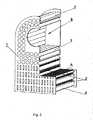
- the heat exchanger tube sethas two heat exchange zones.
- Zone one 1is formed exclusively of smooth tubes 3 circular in cross-section, positioned parallel to one another.
- the combustion chamber 8is positioned inside zone one 1, which is shown on Fig. 1 , Fig. 6 .
- Zone one 1is immediately followed by zone two 2 formed of tubes 4 flat or oval in cross-section, again running parallel to one another, in between which finned elements 5 are fitted formed of a band with profiled plates 6, which is presented on Fig. 3 .
- finned elements 5are fitted formed of a band with profiled plates 6, which is presented on Fig. 3 .
- the plates 6 of the finned element 5are profiled perpendicular to the tubes 4, which is presented on Fig. 8 to Fig. 10 , and in another embodiment at the angle of ⁇ 90°, which is shown on Figures 11 - 15 .
- the plates 6are all inclined in the same direction, which is shown on Fig. 13 and Fig. 15 , or interchangeably inclined in the opposite directions, which is presented on Fig.
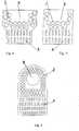
- the tubes 3 of zone one and the tubes 4 of zone twoarc fixed to their respective common sieve bottoms 7, which is shown on Figures 4 to 6 , or - in another embodiment they are fixed to separate sieve bottoms 7. Exemplary shapes of the set are shown on Figures 4 to 6 .
- the fumes formed in the combustion chamber 8first flow around the tubes 3 of zone one 1, where they are cooled, and then penetrate into zone two 2, where they flow around the tubes 4 and finned elements 5, get agitated, and give up their heat.
- the agent circulating in the tubes 3 of zone one 1 and in the tubes 4 of zone two 2takes over the heat.
Landscapes
- Engineering & Computer Science (AREA)
- Physics & Mathematics (AREA)
- Thermal Sciences (AREA)
- Mechanical Engineering (AREA)
- General Engineering & Computer Science (AREA)
- Chemical & Material Sciences (AREA)
- Combustion & Propulsion (AREA)
- Geometry (AREA)
- Heat-Exchange Devices With Radiators And Conduit Assemblies (AREA)
Description
- The invention concerns a heat exchanger tube set, designed for a fuel heat exchanger.
- Known are heat exchangers composed of tubes fixed to sieve bottoms, around which hot fumes flow.
- Also known are heat exchangers composed of tubes fixed to sieve bottoms and fins arranged in between the tubes to increase the heat exchange surface area. Known from patent application
WO 2011/055515 A1 is an element constituting heat exchange fins, fitted in between the tubes. - Also known from
patent application EP 0 860 674 A1 is a heat exchanger composed of a plurality of parallel tubes positioned at a distance from one another, and a plurality of ring fins around the tubes, touching on the tubes. - From
patent application EP 0 618 410 A2 known is heat exchanger for a condensing boiler, in which the pipes from the return to the flow form only one flow path, i.e. are not divided and are arranged either horizontally or upwardly oriented, so that good deaeration can take place, and wherein the actual pipes of the exchanger are arranged close to one another and the row of pipes lying opposite the burner is inclined by 60° to the horizontal, while the burner flame is oriented approximately horizontally. Document GB 1 114 746 A Document EP 0 545 954 A1 discolses a gas-fired water heater with a heat exchanger, designed as a lamina block with water pipes routed through it which terminate in water chambers which are each formed between a base part fixed on the water pipes.Document EP 0 985 895 A2 discloses a heat exchanger unit to be used in a gas-fired water heater in which heater a heat exchanger unit contains tubes with fins. The heat exchanger unit contains flat oval tubes having a fin at least on one flat part. The flat oval tubes as well as the fins are made of copper, copper-based alloy, aluminium or aluminium-based alloy.- Document
FR 2 485 173 A1 - Document
EP 459 785 A - The purpose of this invention is to improve heat exchange parameters and increase the power of the heat exchanger while simultaneously economising on the material.
- The purpose was achieved by designing a tube set consisting of heat exchange zones.
- The heat exchanger tube set according to the invention, designed for a fuel heat exchanger, containing two heat exchange zones created of heat exchange elements in the form of tubes fixed to sieve bottoms, and finned elements filling in the spaces in between the tubes, and immediately after zone one is formed exclusively of smooth tubes, preferably circular in cross section, there is zone two formed of flat or oval tubes with finned elements made of a band with profiled plates fitted in between the tubes, and in the zone one is formed a combustion chamber, wherein the combustion chamber and the tubes in said both zones are positioned horizontally, and said zone two is positioned under said zone one.
- The purpose of zone one is to cool down the fumes initially so as to avoid over-heating and damaging the finned elements of zone two with high temperature, where the purpose of the finned elements is to increase the heat exchange surface area and agitate the agent flowing through them.
- In embodiment of the invention, two or more such bands may run the full height of zone two, in between the respective neighbouring tubes, and the plates may interchangeably inclined in the opposite directions.
- The structure of the set composed of two zones according to the invention enables achieving high power of the heat exchanger while simultaneously economising on the material and increasing the exchanger's durability.
- The positioning of zone two behind zone one which separates zone two from the combustion chamber causes that the cooled fumes in zone one do not over-heat or destroy the plates of the finned elements of zone two, where the purpose of the latter is to increase the heat exchange surface area and agitate the agent flowing through them. Moreover, cooled in zone one, the fumes do not cause overheating of the working agent or bring it to the boiling point.
- The invention is illustrated on the exemplary drawings, where:
Fig. 1 shows the heat exchanger tube set according to the invention in the axonometric projection,Fig. 2 shows the inside of the set,Fig. 3 shows a fragment of zone two,Figures 4 to 6 show the set with different zone configurations in an orthographic projection,Fig. 7 shows the zones of the set,Fig. 8 shows one finned element along the full height of zone two with plates profiled at the right angle to the tubes of zone two,Fig. 9 shows two finned elements with the plates profiled at the right angle to the tubes of zone two,Fig. 10 shows four finned elements with plates profiled at the right angle to the tubes of zone two,Fig. 11 shows one finned element along the full height of zone two with plates profiled at the angle of ≠ 90° to the tubes of zone two,Fig. 12 shows two finned elements with plates profiled at the angle of ≠ 90° to the tube axis, inclined in different directions,Fig. 13 shows two finned elements with plates profiled at the angle of ≠ 90° to the tube axis, all inclined in the same direction,Fig. 14 shows tour finned elements with plates profiled at the angle of ≠ 90° to the tube axis, interchangeably inclined in the opposite directions,Fig. 15 shows four finned elements with plates profiled at the angle of ≠ 90° to the tube axis, all inclined in the same direction.- In accordance with the examples of the invention, the heat exchanger tube set has two heat exchange zones. Zone one 1 is formed exclusively of
smooth tubes 3 circular in cross-section, positioned parallel to one another. Thecombustion chamber 8 is positioned inside zone one 1, which is shown onFig. 1 ,Fig. 6 . Zone one 1 is immediately followed by zone two 2 formed oftubes 4 flat or oval in cross-section, again running parallel to one another, in between which finned elements 5 are fitted formed of a band with profiledplates 6, which is presented onFig. 3 . There is one finned element running along the full height of zone two in between the respective neighbouring tubes, as shown onFig. 8 andFig. 11 . In another embodiment there are two finned elements 5 fitted, which is presented onFig. 9 ,Fig. 12 , andFig. 13 , and in yet another embodiment there is only one finned element 5 fitted in between twotubes 4, which is shown onFig. 10 ,Fig. 14 , andFig. 15 . In one embodiment of the invention theplates 6 of the finned element 5 are profiled perpendicular to thetubes 4, which is presented onFig. 8 to Fig. 10 , and in another embodiment at the angle of ≠ 90°, which is shown onFigures 11 - 15 . In the case of two or several finned elements fitted at the height of zone two 2, theplates 6 are all inclined in the same direction,
which is shown onFig. 13 andFig. 15 , or interchangeably inclined in the opposite directions, which is presented onFig. 12 andFig. 14 . Thetubes 3 of zone one and thetubes 4 of zone two arc fixed to their respective common sieve bottoms 7, which is shown onFigures 4 to 6 , or - in another embodiment they are fixed to separate sieve bottoms 7. Exemplary shapes of the set are shown onFigures 4 to 6 . - The fumes formed in the
combustion chamber 8 first flow around thetubes 3 of zone one 1, where they are cooled, and then penetrate into zone two 2, where they flow around thetubes 4 and finned elements 5, get agitated, and give up their heat. The agent circulating in thetubes 3 of zone one 1 and in thetubes 4 of zone two 2 takes over the heat.
Claims (2)
- A heat exchanger tube set, designed for a fuel heat exchanger, comprising two heat exchange zones, the zone one (1) and the zone two (2), created of heat exchange elements in the form of tubes fixed to sieve bottoms and finned elements filling in the spaces in between the tubes, wherein immediately after the zone one (1) formed exclusively of smooth tubes (3), preferably circular in cross section, there is the zone two (2) formed of flat or oval tubes (4) with finned elements (5) made of a band with profiled plates (6) fitted in between the tubes, wherein in the zone one (1) is formed a combustion chamber, and wherein the combustion chamber and the tubes in said both zones (1, 2) are positioned horizontally, and said zone two (2) is positioned under said zone one (1).
- The set according to Claim 1,characterised in that the plates (6) of the finned element (5) are profiled at an angle different of 90° to the tubes (4) of zone two (2), and they are interchangeably inclined in the opposite directions.
Priority Applications (1)
| Application Number | Priority Date | Filing Date | Title |
|---|---|---|---|
| PL12737914TPL2724106T3 (en) | 2011-06-24 | 2012-06-18 | Heat exchanger tube set |
Applications Claiming Priority (2)
| Application Number | Priority Date | Filing Date | Title |
|---|---|---|---|
| PL395424APL221028B1 (en) | 2011-06-24 | 2011-06-24 | Pipeline package of the heat exchanger |
| PCT/PL2012/000045WO2012177154A1 (en) | 2011-06-24 | 2012-06-18 | Heat exchanger tube set |
Publications (2)
| Publication Number | Publication Date |
|---|---|
| EP2724106A1 EP2724106A1 (en) | 2014-04-30 |
| EP2724106B1true EP2724106B1 (en) | 2019-08-07 |
Family
ID=46548790
Family Applications (1)
| Application Number | Title | Priority Date | Filing Date |
|---|---|---|---|
| EP12737914.7AActiveEP2724106B1 (en) | 2011-06-24 | 2012-06-18 | Heat exchanger tube set |
Country Status (4)
| Country | Link |
|---|---|
| EP (1) | EP2724106B1 (en) |
| ES (1) | ES2746928T3 (en) |
| PL (2) | PL221028B1 (en) |
| WO (1) | WO2012177154A1 (en) |
Families Citing this family (6)
| Publication number | Priority date | Publication date | Assignee | Title |
|---|---|---|---|---|
| JP6449190B2 (en)* | 2016-03-24 | 2019-01-09 | 株式会社ユタカ技研 | Gas water heater |
| US20180372413A1 (en) | 2017-06-22 | 2018-12-27 | Rheem Manufacturing Company | Heat Exchanger Tubes And Tube Assembly Configurations |
| MX2020013259A (en)* | 2018-06-05 | 2021-02-22 | Kyungdong Navien Co Ltd | Heat-exchange pipe, heat-exchanger unit using same, and condensing boiler using same. |
| KR102536797B1 (en)* | 2018-06-05 | 2023-05-26 | 주식회사 경동나비엔 | Heat exchanger unit including heat exchange pipe and condensing boiler using the same |
| MX2020013260A (en) | 2018-06-05 | 2021-02-22 | Kyungdong Navien Co Ltd | Heat exchanger unit and condensing boiler using same. |
| KR102546285B1 (en) | 2019-12-30 | 2023-06-23 | 주식회사 경동나비엔 | Heat exchanger unit |
Citations (5)
| Publication number | Priority date | Publication date | Assignee | Title |
|---|---|---|---|---|
| FR2485173A1 (en)* | 1980-06-18 | 1981-12-24 | Leconte Robert | Central heating unit gas burner - has gas fed to pairs of jets at mains pressure, enclosed by combustion air |
| JPS5932791A (en)* | 1982-08-13 | 1984-02-22 | Hitachi Ltd | Corrugated type heat exchanger |
| EP0459785A1 (en)* | 1990-05-30 | 1991-12-04 | Caradon Heating Limited | Hot water boilers |
| EP0545954A1 (en)* | 1990-09-05 | 1993-06-16 | Bosch Gmbh Robert | Gas-fired water heater. |
| EP0985895A2 (en)* | 1998-09-09 | 2000-03-15 | Outokumpu Oyj | Heat exchanger unit and use |
Family Cites Families (16)
| Publication number | Priority date | Publication date | Assignee | Title |
|---|---|---|---|---|
| BE457244A (en)* | ||||
| FR1411794A (en)* | 1964-08-05 | 1965-09-24 | Improvements to heat exchangers, in particular devices using gaseous fuels for the production of hot water | |
| US3789805A (en)* | 1972-05-17 | 1974-02-05 | Massachusetts Inst Technology | Burner and heat exchanger |
| EP0618410A3 (en)* | 1993-03-02 | 1994-11-23 | Interdomo Gmbh & Co | Heat exchanger for a condensing boiler. |
| WO1995017637A1 (en)* | 1993-12-22 | 1995-06-29 | Teledyne Industries, Inc. | Heat exchanger systems |
| ES2165111T3 (en) | 1994-07-22 | 2002-03-01 | Mitsubishi Electric Corp | HEAT EXCHANGER. |
| JP3600367B2 (en)* | 1996-04-17 | 2004-12-15 | 荏原冷熱システム株式会社 | Absorption chiller hot water regenerator |
| ITPR20010024A1 (en)* | 2001-03-23 | 2002-09-23 | Immergas Spa | HEAT EXCHANGER IN CONDENSING BOILER. |
| US7647897B2 (en)* | 2004-03-25 | 2010-01-19 | Noritz Corporation | Heating apparatus |
| ES2273549B1 (en)* | 2005-01-10 | 2008-04-16 | Jose Maria Vergara Uranga | "A BODY OF CALDEO FOR BOILER OF CONDENSATION". |
| ITBO20050155A1 (en)* | 2005-03-15 | 2006-09-16 | Tec Lab So Co | MONOTHERMAL AND BITERMIC MODULE FOR MURAL CONDENSING BOILERS |
| ITBO20060758A1 (en)* | 2006-11-08 | 2008-05-09 | Gas Point S R L | BOILER WITH COMBUSTION HEAD COOLING SYSTEM |
| JP5151373B2 (en)* | 2006-11-30 | 2013-02-27 | 三浦工業株式会社 | boiler |
| WO2008078211A1 (en)* | 2006-12-20 | 2008-07-03 | Turk Demir Dokum Fabrikalari Anonim Sirketi | A heat exchanger |
| WO2011048574A2 (en)* | 2009-10-21 | 2011-04-28 | Valmex S.P.A. | Improvements to a heat-exchanger for a boiler |
| JP5495720B2 (en) | 2009-11-05 | 2014-05-21 | 臼井国際産業株式会社 | Fin member for heat exchanger |
- 2011
- 2011-06-24PLPL395424Apatent/PL221028B1/enunknown
- 2012
- 2012-06-18ESES12737914Tpatent/ES2746928T3/enactiveActive
- 2012-06-18PLPL12737914Tpatent/PL2724106T3/enunknown
- 2012-06-18EPEP12737914.7Apatent/EP2724106B1/enactiveActive
- 2012-06-18WOPCT/PL2012/000045patent/WO2012177154A1/enactiveApplication Filing
Patent Citations (5)
| Publication number | Priority date | Publication date | Assignee | Title |
|---|---|---|---|---|
| FR2485173A1 (en)* | 1980-06-18 | 1981-12-24 | Leconte Robert | Central heating unit gas burner - has gas fed to pairs of jets at mains pressure, enclosed by combustion air |
| JPS5932791A (en)* | 1982-08-13 | 1984-02-22 | Hitachi Ltd | Corrugated type heat exchanger |
| EP0459785A1 (en)* | 1990-05-30 | 1991-12-04 | Caradon Heating Limited | Hot water boilers |
| EP0545954A1 (en)* | 1990-09-05 | 1993-06-16 | Bosch Gmbh Robert | Gas-fired water heater. |
| EP0985895A2 (en)* | 1998-09-09 | 2000-03-15 | Outokumpu Oyj | Heat exchanger unit and use |
Also Published As
| Publication number | Publication date |
|---|---|
| WO2012177154A1 (en) | 2012-12-27 |
| EP2724106A1 (en) | 2014-04-30 |
| PL2724106T3 (en) | 2020-01-31 |
| ES2746928T3 (en) | 2020-03-09 |
| PL221028B1 (en) | 2016-02-29 |
| PL395424A1 (en) | 2013-01-07 |
Similar Documents
| Publication | Publication Date | Title |
|---|---|---|
| EP2724106B1 (en) | Heat exchanger tube set | |
| JP6763951B2 (en) | Condensin type combustion equipment | |
| US8783334B2 (en) | Heat exchanger particularly for thermal generators | |
| RU2651018C1 (en) | Heat exchanger with u-shaped pipe | |
| KR101717097B1 (en) | Heat exchanger | |
| RU2602947C1 (en) | Condensation heat exchanger with false tubes | |
| EP3021055B1 (en) | Exchanger for heating boilers | |
| KR20110083195A (en) | Condensing boiler | |
| KR20140051522A (en) | Heat exchanger having water housing | |
| US20110067650A1 (en) | Water heater module having detachable heat exchanger | |
| KR20110064718A (en) | Heat exchanger equipped with a combustion chamber and combustion apparatus comprising the same | |
| JP6666124B2 (en) | Combustion device and water heater | |
| JP7336271B2 (en) | Combustion device | |
| KR101717094B1 (en) | Heat exchanger | |
| EP2884201A1 (en) | High-efficiency heat exchanger for boilers and hot air generators | |
| CN107850342A (en) | Heat exchanger | |
| KR20170025475A (en) | Heat exchanger | |
| CN104534667A (en) | Condensing gas heating water heating furnace heat exchanger | |
| JP6630132B2 (en) | Heat exchangers and water heaters | |
| JP4041102B2 (en) | 1 can type combined heat source machine | |
| EP3426986B1 (en) | Sectional heat exchanger for use in a heat cell | |
| KR200284723Y1 (en) | Heat Exchanger of Gas Boiler for Home use | |
| KR20150134177A (en) | The cooling system of the heat exchanger | |
| RU141982U1 (en) | WATER BOILER | |
| CN118347032A (en) | Pot rack and kitchen range |
Legal Events
| Date | Code | Title | Description |
|---|---|---|---|
| PUAI | Public reference made under article 153(3) epc to a published international application that has entered the european phase | Free format text:ORIGINAL CODE: 0009012 | |
| 17P | Request for examination filed | Effective date:20140108 | |
| AK | Designated contracting states | Kind code of ref document:A1 Designated state(s):AL AT BE BG CH CY CZ DE DK EE ES FI FR GB GR HR HU IE IS IT LI LT LU LV MC MK MT NL NO PL PT RO RS SE SI SK SM TR | |
| DAX | Request for extension of the european patent (deleted) | ||
| STAA | Information on the status of an ep patent application or granted ep patent | Free format text:STATUS: EXAMINATION IS IN PROGRESS | |
| 17Q | First examination report despatched | Effective date:20180321 | |
| GRAP | Despatch of communication of intention to grant a patent | Free format text:ORIGINAL CODE: EPIDOSNIGR1 | |
| STAA | Information on the status of an ep patent application or granted ep patent | Free format text:STATUS: GRANT OF PATENT IS INTENDED | |
| RIC1 | Information provided on ipc code assigned before grant | Ipc:F24H 1/34 20060101ALI20190222BHEP Ipc:F28D 7/16 20060101AFI20190222BHEP Ipc:F24H 8/00 20060101ALI20190222BHEP Ipc:F28F 1/02 20060101ALI20190222BHEP Ipc:F28F 1/12 20060101ALI20190222BHEP Ipc:F24H 1/40 20060101ALI20190222BHEP | |
| INTG | Intention to grant announced | Effective date:20190312 | |
| GRAS | Grant fee paid | Free format text:ORIGINAL CODE: EPIDOSNIGR3 | |
| GRAA | (expected) grant | Free format text:ORIGINAL CODE: 0009210 | |
| STAA | Information on the status of an ep patent application or granted ep patent | Free format text:STATUS: THE PATENT HAS BEEN GRANTED | |
| AK | Designated contracting states | Kind code of ref document:B1 Designated state(s):AL AT BE BG CH CY CZ DE DK EE ES FI FR GB GR HR HU IE IS IT LI LT LU LV MC MK MT NL NO PL PT RO RS SE SI SK SM TR | |
| REG | Reference to a national code | Ref country code:GB Ref legal event code:FG4D | |
| REG | Reference to a national code | Ref country code:CH Ref legal event code:EP Ref country code:AT Ref legal event code:REF Ref document number:1164529 Country of ref document:AT Kind code of ref document:T Effective date:20190815 | |
| REG | Reference to a national code | Ref country code:DE Ref legal event code:R096 Ref document number:602012062683 Country of ref document:DE | |
| REG | Reference to a national code | Ref country code:IE Ref legal event code:FG4D | |
| REG | Reference to a national code | Ref country code:NL Ref legal event code:FP | |
| REG | Reference to a national code | Ref country code:CH Ref legal event code:NV Representative=s name:MICHELI AND CIE SA, CH | |
| REG | Reference to a national code | Ref country code:LT Ref legal event code:MG4D | |
| PG25 | Lapsed in a contracting state [announced via postgrant information from national office to epo] | Ref country code:FI Free format text:LAPSE BECAUSE OF FAILURE TO SUBMIT A TRANSLATION OF THE DESCRIPTION OR TO PAY THE FEE WITHIN THE PRESCRIBED TIME-LIMIT Effective date:20190807 Ref country code:BG Free format text:LAPSE BECAUSE OF FAILURE TO SUBMIT A TRANSLATION OF THE DESCRIPTION OR TO PAY THE FEE WITHIN THE PRESCRIBED TIME-LIMIT Effective date:20191107 Ref country code:SE Free format text:LAPSE BECAUSE OF FAILURE TO SUBMIT A TRANSLATION OF THE DESCRIPTION OR TO PAY THE FEE WITHIN THE PRESCRIBED TIME-LIMIT Effective date:20190807 Ref country code:NO Free format text:LAPSE BECAUSE OF FAILURE TO SUBMIT A TRANSLATION OF THE DESCRIPTION OR TO PAY THE FEE WITHIN THE PRESCRIBED TIME-LIMIT Effective date:20191107 Ref country code:PT Free format text:LAPSE BECAUSE OF FAILURE TO SUBMIT A TRANSLATION OF THE DESCRIPTION OR TO PAY THE FEE WITHIN THE PRESCRIBED TIME-LIMIT Effective date:20191209 Ref country code:HR Free format text:LAPSE BECAUSE OF FAILURE TO SUBMIT A TRANSLATION OF THE DESCRIPTION OR TO PAY THE FEE WITHIN THE PRESCRIBED TIME-LIMIT Effective date:20190807 Ref country code:LT Free format text:LAPSE BECAUSE OF FAILURE TO SUBMIT A TRANSLATION OF THE DESCRIPTION OR TO PAY THE FEE WITHIN THE PRESCRIBED TIME-LIMIT Effective date:20190807 | |
| PG25 | Lapsed in a contracting state [announced via postgrant information from national office to epo] | Ref country code:AL Free format text:LAPSE BECAUSE OF FAILURE TO SUBMIT A TRANSLATION OF THE DESCRIPTION OR TO PAY THE FEE WITHIN THE PRESCRIBED TIME-LIMIT Effective date:20190807 Ref country code:GR Free format text:LAPSE BECAUSE OF FAILURE TO SUBMIT A TRANSLATION OF THE DESCRIPTION OR TO PAY THE FEE WITHIN THE PRESCRIBED TIME-LIMIT Effective date:20191108 Ref country code:LV Free format text:LAPSE BECAUSE OF FAILURE TO SUBMIT A TRANSLATION OF THE DESCRIPTION OR TO PAY THE FEE WITHIN THE PRESCRIBED TIME-LIMIT Effective date:20190807 Ref country code:RS Free format text:LAPSE BECAUSE OF FAILURE TO SUBMIT A TRANSLATION OF THE DESCRIPTION OR TO PAY THE FEE WITHIN THE PRESCRIBED TIME-LIMIT Effective date:20190807 Ref country code:IS Free format text:LAPSE BECAUSE OF FAILURE TO SUBMIT A TRANSLATION OF THE DESCRIPTION OR TO PAY THE FEE WITHIN THE PRESCRIBED TIME-LIMIT Effective date:20191207 | |
| REG | Reference to a national code | Ref country code:ES Ref legal event code:FG2A Ref document number:2746928 Country of ref document:ES Kind code of ref document:T3 Effective date:20200309 | |
| PG25 | Lapsed in a contracting state [announced via postgrant information from national office to epo] | Ref country code:RO Free format text:LAPSE BECAUSE OF FAILURE TO SUBMIT A TRANSLATION OF THE DESCRIPTION OR TO PAY THE FEE WITHIN THE PRESCRIBED TIME-LIMIT Effective date:20190807 Ref country code:DK Free format text:LAPSE BECAUSE OF FAILURE TO SUBMIT A TRANSLATION OF THE DESCRIPTION OR TO PAY THE FEE WITHIN THE PRESCRIBED TIME-LIMIT Effective date:20190807 Ref country code:EE Free format text:LAPSE BECAUSE OF FAILURE TO SUBMIT A TRANSLATION OF THE DESCRIPTION OR TO PAY THE FEE WITHIN THE PRESCRIBED TIME-LIMIT Effective date:20190807 | |
| PG25 | Lapsed in a contracting state [announced via postgrant information from national office to epo] | Ref country code:SK Free format text:LAPSE BECAUSE OF FAILURE TO SUBMIT A TRANSLATION OF THE DESCRIPTION OR TO PAY THE FEE WITHIN THE PRESCRIBED TIME-LIMIT Effective date:20190807 Ref country code:CZ Free format text:LAPSE BECAUSE OF FAILURE TO SUBMIT A TRANSLATION OF THE DESCRIPTION OR TO PAY THE FEE WITHIN THE PRESCRIBED TIME-LIMIT Effective date:20190807 Ref country code:IS Free format text:LAPSE BECAUSE OF FAILURE TO SUBMIT A TRANSLATION OF THE DESCRIPTION OR TO PAY THE FEE WITHIN THE PRESCRIBED TIME-LIMIT Effective date:20200224 Ref country code:SM Free format text:LAPSE BECAUSE OF FAILURE TO SUBMIT A TRANSLATION OF THE DESCRIPTION OR TO PAY THE FEE WITHIN THE PRESCRIBED TIME-LIMIT Effective date:20190807 | |
| REG | Reference to a national code | Ref country code:DE Ref legal event code:R097 Ref document number:602012062683 Country of ref document:DE | |
| PLBE | No opposition filed within time limit | Free format text:ORIGINAL CODE: 0009261 | |
| STAA | Information on the status of an ep patent application or granted ep patent | Free format text:STATUS: NO OPPOSITION FILED WITHIN TIME LIMIT | |
| PG2D | Information on lapse in contracting state deleted | Ref country code:IS | |
| 26N | No opposition filed | Effective date:20200603 | |
| PG25 | Lapsed in a contracting state [announced via postgrant information from national office to epo] | Ref country code:SI Free format text:LAPSE BECAUSE OF FAILURE TO SUBMIT A TRANSLATION OF THE DESCRIPTION OR TO PAY THE FEE WITHIN THE PRESCRIBED TIME-LIMIT Effective date:20190807 | |
| PG25 | Lapsed in a contracting state [announced via postgrant information from national office to epo] | Ref country code:MC Free format text:LAPSE BECAUSE OF FAILURE TO SUBMIT A TRANSLATION OF THE DESCRIPTION OR TO PAY THE FEE WITHIN THE PRESCRIBED TIME-LIMIT Effective date:20190807 | |
| PGFP | Annual fee paid to national office [announced via postgrant information from national office to epo] | Ref country code:IE Payment date:20201014 Year of fee payment:9 | |
| REG | Reference to a national code | Ref country code:AT Ref legal event code:UEP Ref document number:1164529 Country of ref document:AT Kind code of ref document:T Effective date:20190807 | |
| PG25 | Lapsed in a contracting state [announced via postgrant information from national office to epo] | Ref country code:LU Free format text:LAPSE BECAUSE OF NON-PAYMENT OF DUE FEES Effective date:20200618 | |
| PG25 | Lapsed in a contracting state [announced via postgrant information from national office to epo] | Ref country code:IE Free format text:LAPSE BECAUSE OF NON-PAYMENT OF DUE FEES Effective date:20210618 | |
| PG25 | Lapsed in a contracting state [announced via postgrant information from national office to epo] | Ref country code:MT Free format text:LAPSE BECAUSE OF FAILURE TO SUBMIT A TRANSLATION OF THE DESCRIPTION OR TO PAY THE FEE WITHIN THE PRESCRIBED TIME-LIMIT Effective date:20190807 Ref country code:CY Free format text:LAPSE BECAUSE OF FAILURE TO SUBMIT A TRANSLATION OF THE DESCRIPTION OR TO PAY THE FEE WITHIN THE PRESCRIBED TIME-LIMIT Effective date:20190807 | |
| PG25 | Lapsed in a contracting state [announced via postgrant information from national office to epo] | Ref country code:MK Free format text:LAPSE BECAUSE OF FAILURE TO SUBMIT A TRANSLATION OF THE DESCRIPTION OR TO PAY THE FEE WITHIN THE PRESCRIBED TIME-LIMIT Effective date:20190807 | |
| PGFP | Annual fee paid to national office [announced via postgrant information from national office to epo] | Ref country code:NL Payment date:20240628 Year of fee payment:13 | |
| PGFP | Annual fee paid to national office [announced via postgrant information from national office to epo] | Ref country code:AT Payment date:20240628 Year of fee payment:13 | |
| PGFP | Annual fee paid to national office [announced via postgrant information from national office to epo] | Ref country code:FR Payment date:20240628 Year of fee payment:13 | |
| PGFP | Annual fee paid to national office [announced via postgrant information from national office to epo] | Ref country code:TR Payment date:20240620 Year of fee payment:13 | |
| PGFP | Annual fee paid to national office [announced via postgrant information from national office to epo] | Ref country code:IT Payment date:20240628 Year of fee payment:13 | |
| PGFP | Annual fee paid to national office [announced via postgrant information from national office to epo] | Ref country code:DE Payment date:20240703 Year of fee payment:13 | |
| PGFP | Annual fee paid to national office [announced via postgrant information from national office to epo] | Ref country code:GB Payment date:20240719 Year of fee payment:13 | |
| PGFP | Annual fee paid to national office [announced via postgrant information from national office to epo] | Ref country code:CH Payment date:20240718 Year of fee payment:13 Ref country code:ES Payment date:20240718 Year of fee payment:13 | |
| PGFP | Annual fee paid to national office [announced via postgrant information from national office to epo] | Ref country code:PL Payment date:20250609 Year of fee payment:14 | |
| PGFP | Annual fee paid to national office [announced via postgrant information from national office to epo] | Ref country code:BE Payment date:20250626 Year of fee payment:14 |