EP2721784B1 - Method of operation of a network equipment and network equipment - Google Patents
Method of operation of a network equipment and network equipmentDownload PDFInfo
- Publication number
- EP2721784B1 EP2721784B1EP12759068.5AEP12759068AEP2721784B1EP 2721784 B1EP2721784 B1EP 2721784B1EP 12759068 AEP12759068 AEP 12759068AEP 2721784 B1EP2721784 B1EP 2721784B1
- Authority
- EP
- European Patent Office
- Prior art keywords
- network
- vlan
- switch
- port
- switch device
- Prior art date
- Legal status (The legal status is an assumption and is not a legal conclusion. Google has not performed a legal analysis and makes no representation as to the accuracy of the status listed.)
- Active
Links
- 238000000034methodMethods0.000titleclaimsdescription34
- 238000004891communicationMethods0.000claimsdescription23
- 230000008878couplingEffects0.000claimsdescription8
- 238000010168coupling processMethods0.000claimsdescription8
- 238000005859coupling reactionMethods0.000claimsdescription8
- 238000004590computer programMethods0.000claimsdescription7
- 238000013500data storageMethods0.000claims1
- 238000006798ring closing metathesis reactionMethods0.000description9
- 230000005540biological transmissionEffects0.000description5
- 230000002093peripheral effectEffects0.000description2
- 238000000926separation methodMethods0.000description2
- 238000007792additionMethods0.000description1
- 230000002457bidirectional effectEffects0.000description1
- 230000015556catabolic processEffects0.000description1
- 230000009849deactivationEffects0.000description1
- 230000001419dependent effectEffects0.000description1
- 238000005259measurementMethods0.000description1
- 238000012986modificationMethods0.000description1
- 230000004048modificationEffects0.000description1
- 230000008569processEffects0.000description1
- 230000004044responseEffects0.000description1
Images


Classifications
- H—ELECTRICITY
- H04—ELECTRIC COMMUNICATION TECHNIQUE
- H04L—TRANSMISSION OF DIGITAL INFORMATION, e.g. TELEGRAPHIC COMMUNICATION
- H04L12/00—Data switching networks
- H04L12/28—Data switching networks characterised by path configuration, e.g. LAN [Local Area Networks] or WAN [Wide Area Networks]
- H04L12/42—Loop networks
- H04L12/437—Ring fault isolation or reconfiguration
- H—ELECTRICITY
- H04—ELECTRIC COMMUNICATION TECHNIQUE
- H04L—TRANSMISSION OF DIGITAL INFORMATION, e.g. TELEGRAPHIC COMMUNICATION
- H04L12/00—Data switching networks
- H04L12/28—Data switching networks characterised by path configuration, e.g. LAN [Local Area Networks] or WAN [Wide Area Networks]
- H04L12/46—Interconnection of networks
- H04L12/4641—Virtual LANs, VLANs, e.g. virtual private networks [VPN]
- H—ELECTRICITY
- H04—ELECTRIC COMMUNICATION TECHNIQUE
- H04L—TRANSMISSION OF DIGITAL INFORMATION, e.g. TELEGRAPHIC COMMUNICATION
- H04L41/00—Arrangements for maintenance, administration or management of data switching networks, e.g. of packet switching networks
- H04L41/12—Discovery or management of network topologies
- H04L41/122—Discovery or management of network topologies of virtualised topologies, e.g. software-defined networks [SDN] or network function virtualisation [NFV]
- H—ELECTRICITY
- H04—ELECTRIC COMMUNICATION TECHNIQUE
- H04L—TRANSMISSION OF DIGITAL INFORMATION, e.g. TELEGRAPHIC COMMUNICATION
- H04L49/00—Packet switching elements
- H04L49/30—Peripheral units, e.g. input or output ports
Definitions
- the present inventionrelates to a method for operating a network arrangement, as well as a network arrangement, which works with the proposed method.
- the method of operationcan be used in particular in an Ethernet environment.
- Communication networksare finding ever wider application for measuring, controlling and controlling complex technical systems. For example, networks are increasingly being used in motor vehicles to form vehicle control systems. In corresponding complex and safety-relevant technical systems, high demands are placed on the availability of the control elements provided as network devices. In the event of failure of individual components, such as sensors or control devices, this must not lead to the failure of the entire system. Particularly safety-relevant are drive-by-wire systems in which the steering wheel position is converted into wheel positions by an electric motor via a network coupling of sensor, control and actuator devices.
- datais to be frequently exchanged over a packet-based communication network in such a way that, in the case of a simple error in the communication network, the data arrives without loss of information.
- datacan be sent multiple times from a source to a destination node so that the data can be reliably obtained even in the event of a network interruption.
- HASRHigh Availability Seamless Redundancy
- PRPParallel Redundancy Protocol
- ring structurescan be implemented only with great effort.
- US 2010/0020809 A1there is provided a method in which a VLAN in an Ethernet network is organized as a ring structure. Each node is assigned a switch that interrupts the ring at a suitable location and operating situation.
- the US 2009/122695 A1discloses a method for redundant ring communication with multiple communication modules.
- Each communication modulehas a pair of ring-channel ports for a ring-configured channel in a network, a peripheral device port for peripheral device data, and dual-ring ports for an inter-ring channel for a respective pair of modules.
- the first and second of a set of communication modulessend duplicated data packets on their respective first and second rings.
- each of the next modulestransmits its data packet received via the respective ring channel via a downstream ring channel port.
- the US 2008/095047 A1discloses a method for looping back traffic in QIQ Ethernet rings and 1: 1 protected PBT trunks.
- a robust virtual Ethernet ringhas nodes interconnected by work and protection paths. If an area fails, the direct two adjacent nodes of the failure are immediately connected to close the ring.
- Workpath trafficis connected to the protection path at the first of the two nodes and then reconnected to the workpath at the second node of the two nodes so that traffic enters and exits the ring at any time via the work path.
- An originating node of the trafficis arranged to switch the transmission of data packets from a first path to a second path as soon as it is detected that transmitted packets are looped back due to an error on the first path.
- the "one VLAN”is understood as meaning a first VLAN and, under the "other VLAN", a second VLAN implemented independently of the first VLAN.
- the VLANsare implemented in the same network infrastructure.
- a VLANseparates physical networks into logical subnets, which act essentially independently of each other.
- the network devicescan also be referred to as network nodes, subscribers in a network or as control components.
- VLANsSimultaneously deploying multiple VLANs allows data to be sent and received redundantly and simultaneously across the network infrastructure. This achieves improved error protection.
- Deactivating certain portsprevents data packets in the ring structure from being constantly forwarded and can lead to unwanted ring closure of the network.
- the annular communication pathis interrupted by a sending network device.
- Data received twicefor example data arriving via the various VLANs, can be sorted out at the destination node or the destination network device via known methods.
- process aspects of the PRP or HASR protocolare suitable.
- a redundant opening of the respective VLAN ringis achieved. For example, in the case of an error in forward tables of a respective switch, the situation may arise that an unintentional ring closure occurs in the VLAN, as a result of which the network may collapse. By the additional Disabling a further (adjacent) port in the communication path of the ring structure this is practically prevented.
- itfurther comprises: sending the data packet from the controller of the selected network device via the other port of the switch device to the other of the two VLANs;
- the packetis sent simultaneously to the two VLANs.
- thiscan be done in particular using a unicast address, a multicast address or a broadcast address.
- all ports of the switch devices in the network arrangementare activated for a respective VLAN, with the exception of that port of a switching device of a sending network device from which the data packet is not sent.
- the other non-sending portinterrupts the ring of the VLAN into which the data is sent.
- a network arrangement with a network device coupled together in a ring structure according to claim 10is also proposed.
- the network devicesare preferably set up in such a way to carry out a method as described above.
- At least one network devicecomprises a first and a second switch device, wherein the first switch device is assigned to the first control device and the second switch device is assigned to a second control device.
- the switch deviceseach comprise at least two ports and are communicatively coupled with each other.
- control devicessuch as a CPU, a microprocessor or other programmable circuits, can perform particularly safety-related tasks.
- the redundant versionalso makes it possible to send consistent data across several VLANs and to provide it in the network.
- FIG. 1For example, a first and a second ring structure is formed, wherein the ring structures are coupled by means of one or more coupling switch devices.
- the ring structuresmay be coupled by the coupling switch devices such that ports of the coupling switch devices are each activated for only one of the VLANs.
- a separation or separation of the used VLANis done by the coupling switch device.
- the two ring structurescan have two separate physical lines.
- the network arrangementmay in particular be part of a vehicle. Conceivable, however, are other applications such as automation networks.
- the network devicesare each implemented as a single FPGA, ASIC, IC chip, or hard-wired microcircuit.
- a computer program productsuch as a computer program means can be provided or supplied, for example, as a storage medium, such as a memory card, USB stick, CD-ROM, DVD or in the form of a downloadable file from a server in a network. This can be done, for example, in a wireless communication network by the transmission of a corresponding file with the computer program product or the computer program means.
- a program-controlled deviceis a network device as described above.
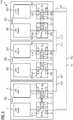
- the Fig. 1shows a schematic representation of a first embodiment of a network arrangement.
- the network arrangementmay for example be embedded in an Ethernet structure and comprise a plurality of network devices, which may also be referred to as network nodes, network users or as control components. Names such as network elements or network components are also common.
- a respective network device 1which is labeled as "node 1", “node 2" and “node 3”, each comprises a control device 2, 202, 302, which may be configured, for example, as a microprocessor or CPU.
- the controller 2, 202, 302can perform certain functions in the network. Functions as an actuator or sensor measurements are conceivable.
- the respective CPU 2, 202, 302is assigned a switch device 4, 204, 304.
- the switch device 4, 204, 304comprises a first port 7, 207, 307, which is communicatively connected to the respective CPU 2, 202, 302.
- each switch device 4, 204, 304which is designed, for example, as an internal Ethernet switch, has two further ports 8, 9, 208, 209, 308, 309 for coupling to a communication network 6, which contains the data lines and thus communication paths for data packets exchanged between the network devices 1, 201, 301.
- the network arrangement 101is operated by providing two VLAN networks VL1, VL2.
- the network devices 1, 201, 301are arranged in a ring structure. That is, between the network device 1 and 201 is a communicative connection, for example, in the manner of a cable or another network link. Further, the network device 201 is communicatively coupled to the network device 301, and the network device 301 is coupled to the network device 1. This allows a ring structure for the VLANs VL1, VL2.
- VLAN ring VL1is realized by potential data paths between the port 9 of the first switch device 4, the ports 208, 209 of the second switch device 204, the ports 308, 309 of the third switch device 304 and (but deactivated) the Port 8 of the first switch device 4.
- the network device 1is a sending network device, thus supplying data to the other existing network nodes 201, 301.
- the second VLAN VL2is in the manner of a ring through a communication path between the port 8 of the first switch device 4, the port 309 of third switch device 304, the port 308 of the third switch device 304 and the port 209 of the second switch device 204 and between the port 208 of the second switch device 204 and the (switched off for the VLAN VL2) port 9 of the first switch Device 4.
- the sending network device 1that is, when the CPU 2 transfers data via the port 7 to the switch device 4, the data is transmitted on the one hand via the VLAN VL1 and on the other hand via the VLAN VL2.
- the first port 8is activated for the VLAN VL2, whereas the other port 9 for the VLAN VL2 is deactivated.
- port 9is enabled for VLAN VL1 and the other port 8 is disabled for VLAN VL1.
- the respective disabled portinterrupts an unwanted ring closure in the VLAN.
- all portsare activated in a VLAN, except the non-sending port of the source node, which is in the Fig. 1 the network device 1 is.
- Broadcast or multicast destination addressesmay be used for transmission so that in the ring network all other nodes or network devices 201, 301 receive the data. Also conceivable are unicast addresses to reach individual control devices.
- FIG. 2shows essentially the same elements as in the Fig. 1 and shows two provided VLAN rings VL1 and VL2.
- the network devices 1, 201, 301are configured with their switch devices 4, 204, 304 such that adjacent ports of different network devices 1, 201, 301 also forward data packets in a respective VLAN that could cause the ring to close.
- the port 8 not used for transmissionis deactivated for the VLAN VL1 from the transmitting network device 1 or the node 1.
- both the port 8 of the transmitting network device 1 and the port 309 of the network device 301 receiving from the other VLAN VL2are deactivated.
- port 9 and 208 for VLAN VL2are disabled or disabled.
- the Fig. 3shows a further embodiment of a network arrangement 110.
- the network devices 100, 200, 300 usedare redundant, each with two CPUs 2, 3, 202, 203, 302, 303 and associated switch devices 4, 5, 204, 205, 304, 305 fitted.
- the switch devices of a network nodeare each communicatively coupled with each other.
- the switch device 4is coupled to the switch device 5 internally via ports 11, 12.
- the switch device 204, 205 of the second node 200are also internally coupled to each other via ports 211, 212.
- the switch devices 304, 305 of the third node 300are coupled together via the ports 311, 312.
- the data of the redundant CPUswhich are referred to as "channel a" and “channel b", are linked together via a coding.
- datamay be generated by the CPU 2 that corresponds to a bit inversion of the data from CPU 3.
- the respective data from channels A and Bcan then be compared, and errors in data transmission can be inferred, or failures of network devices can be determined.
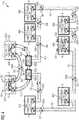
- the Fig. 4 and 5show a fourth embodiment of a network arrangement 101.
- the network arrangement 111may be part of a motor vehicle, are configured in the control components and various actuators, so adjusting elements as network devices.
- two ring structuresare formed, which are coupled to one another via central Ethernet switches 501, 502.
- two control components or network devices 100, 200are coupled to one another with the two Ethernet switches 501, 502 in a ring.
- Another second ringis formed by network devices 400, labeled "Actuator 1" through “Actuator 6".
- the actuator devices 400each have an Ethernet switch 4 and are substantially the same as those in FIG Fig. 1 illustrated network device 1 constructed. No CPUs are shown in the actuator devices 400.
- the network arrangement 111is based on an Ethernet protocol. This means that bidirectional or duplex connections are possible. This means that data communication can take place in two directions.
- a first virtual LAN VL1for sending data from the control component 100 to the actuator component 400, which is labeled "actuator 3".
- the respective communication directionis indicated by the arrows between the network components 100, 200, 400, 500 indicated.
- the data packets DGcorrespond to those which run via the left branch, that is to say from the control component 100 via the switch device 501 and the actuator devices 400, which are designated "Actuator 1" and "Actuator 2".
- the data packets DGAare returning data packets.
- a right branch with data packets DB or DBAruns from the control component 100 to the control component 200 via the switch device 502 and the network devices 400 designated “Actuator 4" to "Actuator 6".
- FIG. 5the operating situation of the network with the second VLAN VL2 is shown.
- the network pathsare shaded underlined indicated.
- the first Ethernet switch device 501 or its ports 507, 508, 509is deactivated. That is, there can be no network overload caused by circulating data packets.
- the in the FIGS. 4 to 7 Ported with individual reference numbersare combinations of transmit and receive ports. Based on the arrows indicating a data direction, and the symbols "s" and "r” results respectively, which port is addressed or disabled. For example, in FIG. 4 the send port "s" of the port combination 509 of the switch device 508 for the VLAN VL1 is deactivated.
- VL1As stated in the Fig. 4 is indicated, and VL2, as in the Fig. 5 is indicated, are operated simultaneously, so that data simultaneously from the control component 1, 100 to be controlled actuator component actuator 3, 400. Even if data packets which are transmitted via a first VLAN VL1 are disturbed, the Actuator component 3, 400 nevertheless reliable data on the second VLAN VL2.
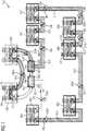
- FIG. 6 and 7show a network arrangement 112, which essentially the same components as the network arrangement 111 of the Fig. 4 and 5 having.
- a VLAN VL1is likewise provided (cf. Fig. 6 ) and a VLAN VL2 (cf. Fig. 7 ).
- the VLAN VL1is indicated by dots and the VLAN VL2 is hatched diagonally.
- the Ethernet switch 502 or its ports 507, 508, 509is deactivated. There is no forwarding of data packets that correspond to the VL1.
- the ports 207 of the adjacent control component 2, 200are deactivated and the ports 407 of the actuator component 6, 400 likewise adjacent to the second ring. In this respect, the delimitation or termination of the VLAN ring VL1 is additionally improved. Even with errors in forwarding tables, for example in the Ethernet switch 502, the ports 407 and 207 of the actuator component 6, 400 and the control component 2, 200 stop the corresponding data packets.
- the Ethernet switch 501 or its ports 507, 508, 509are blocked for the VLAN VL2.
- the adjacent ports 207, 407 of the control component 1, 100 of the upper ring structure and the actuator device 400 of the lower ring structureare deactivated. In this respect, even in the event of errors in forwarding tables of the Ethernet switch 501, it can be reliably prevented that data packets of the VLAN VL2 run in a circle and thus burden the network infrastructure unnecessarily.
- VLAN cross-connectcan be made between source and destination nodes (VLAN-XC) or methods such as provider backbound bridging - traffic engineering (PBB-TE) can be used.
- PBB-TEprovider backbound bridging - traffic engineering
- PRPcan be used for the ring-shaped VLANs used, since several VLANs are provided simultaneously.
- VL1, VL2are indicated in the examples, it is also possible to provide further VLANs by extending the port deactivation. Implementing more than two VLANs will further improve communication security.
Landscapes
- Engineering & Computer Science (AREA)
- Computer Networks & Wireless Communication (AREA)
- Signal Processing (AREA)
- Computer Security & Cryptography (AREA)
- Small-Scale Networks (AREA)
Description
Translated fromGermanDie vorliegende Erfindung betrifft ein Verfahren zum Betreiben einer Netzwerkanordnung, sowie eine Netzwerkanordnung, welche mit dem vorgeschlagenen Verfahren arbeitet. Das Verfahren zum Betreiben kann insbesondere in einer Ethernet-Umgebung zum Einsatz kommen.The present invention relates to a method for operating a network arrangement, as well as a network arrangement, which works with the proposed method. The method of operation can be used in particular in an Ethernet environment.
Kommunikationsnetzwerke finden immer breitere Anwendung zum Messen, Steuern und Regeln komplexer technischer Systeme. Beispielsweise werden zunehmend Netzwerke in Kraftfahrzeugen eingesetzt, um Fahrzeugsteuerungssysteme auszubilden. In entsprechenden komplexen und sicherheitsrelevanten technischen Systemen werden hohe Anforderungen an die Verfügbarkeit der als Netzwerkeinrichtungen vorgesehenen Steuerungselemente gestellt. Beim Ausfall von einzelnen Komponenten, wie beispielsweise Sensoren oder Steuereinrichtungen, darf dies nicht zum Ausfall des Gesamtsystems führen. Besonders sicherheitsrelevant sind Drive-by-Wire-Systeme, bei denen elektromotorisch über eine Netzwerkkopplung von Sensor-, Steuer- und Aktoreinrichtungen die Lenkradstellung in Radpositionen umgesetzt wird.Communication networks are finding ever wider application for measuring, controlling and controlling complex technical systems. For example, networks are increasingly being used in motor vehicles to form vehicle control systems. In corresponding complex and safety-relevant technical systems, high demands are placed on the availability of the control elements provided as network devices. In the event of failure of individual components, such as sensors or control devices, this must not lead to the failure of the entire system. Particularly safety-relevant are drive-by-wire systems in which the steering wheel position is converted into wheel positions by an electric motor via a network coupling of sensor, control and actuator devices.
Dabei sollen häufig über ein paketbasiertes Kommunikationsnetzwerk Daten derart ausgetauscht werden, dass im Falle eines einfachen Fehlers im Kommunikationsnetz die Daten ohne Informationsverlust ankommen. Beispielsweise können Daten mehrfach von einem Quell- zu einem Zielknoten geschickt werden, damit auch bei einer Netzwerkstörung zuverlässig die Daten erhalten werden können. Für Ethernet-Anwendungen ist beispielsweise das HASR-Protokoll (High Availability Seamless Redundancy) bekannt. HASR erfordert aber eine Ringstruktur des Netzwerkes, was grundsätzlich für Ethernet-Netze problematisch ist. Das ebenfalls bekannte Protokoll PRP (Parallel Redundancy Protocol) erfordert zwei parallele Netzwerke.In this case, data is to be frequently exchanged over a packet-based communication network in such a way that, in the case of a simple error in the communication network, the data arrives without loss of information. For example, data can be sent multiple times from a source to a destination node so that the data can be reliably obtained even in the event of a network interruption. For Ethernet applications, for example, the HASR protocol (High Availability Seamless Redundancy) is known. However, HASR requires a ring structure of the network, which is fundamentally problematic for Ethernet networks. The likewise known protocol PRP (Parallel Redundancy Protocol) requires two parallel networks.
Insbesondere bei Netzwerken, die auf dem Ethernet-Standard basieren, sind Ringstrukturen nur mit hohem Aufwand implementierbar. In der
Die
Die
Es ist wünschenswert, insbesondere auf einer Ethernet-Struktur aufbauende Datenkommunikation zu betreiben, die einen erhöhten Fehlerschutz hat. Dies erfordert in der Regel, dass zwei disjunkte Kommunikationspfade von einer Datenquelle zu einem Zielknoten realisiert sind.It is desirable, in particular, to operate data communication based on an Ethernet structure, which has increased error protection. This typically requires that two disjoint communication paths be realized from a data source to a destination node.
Es ist daher eine Aufgabe der vorliegenden Erfindung, ein verbessertes Verfahren und/oder eine Netzwerkanordnung bereitzustellen.It is therefore an object of the present invention to provide an improved method and / or network arrangement.
Demgemäß wird ein Verfahren zum Betreiben einer Netzwerkanordnung mit mehreren in einer Ringstruktur aneinander gekoppelten Netzwerkeinrichtungen gemäß Anspruch 1 vorgeschlagen.Accordingly, a method for operating a network arrangement with a plurality of network devices coupled together in a ring structure according to
Dabei wird unter dem "einen VLAN" ein erstes VLAN verstanden und unter dem "anderen VLAN" ein zweites unabhängig von dem ersten VLAN implementiertes VLAN. Die VLANs sind in derselben Netzwerkinfrastruktur implementiert. Ein VLAN trennt physische Netze in logische Teilnetze auf, die im Wesentlichen unabhängig voneinander agieren.In this case, the "one VLAN" is understood as meaning a first VLAN and, under the "other VLAN", a second VLAN implemented independently of the first VLAN. The VLANs are implemented in the same network infrastructure. A VLAN separates physical networks into logical subnets, which act essentially independently of each other.
Die Netzwerkeinrichtungen können auch als Netzwerkknoten, Teilnehmer in einem Netzwerk oder auch als Steuerungskomponenten bezeichnet werden.The network devices can also be referred to as network nodes, subscribers in a network or as control components.
Durch das gleichzeitige Bereitstellen von mehreren VLANs können Daten redundant und gleichzeitig über die Netzwerk-Infrastruktur versendet und empfangen werden. Dadurch wird ein verbesserter Fehlerschutz erreicht. Viele Netzwerk-Protokolle wie das Ethernet verbieten die Ausführung von Ringstrukturen, da konventioneller Weise der Ringschluss ein Zusammenbruch des Netzwerkes nach sich ziehen kann, weil Datenpakete unendlich oft im Kreis verlaufen können. Deshalb ist vorgesehen, dass bestimmte Ports der Switch-Einrichtungen für das eine oder andere VLAN deaktiviert sind. Insofern erhält man, beispielsweise zwei ineinander greifende Ringstrukturen, welche von einer sendenden Netzwerkeinrichtung bzw. ein Port der zugehörigen Switch-Einrichtung terminiert wird.Simultaneously deploying multiple VLANs allows data to be sent and received redundantly and simultaneously across the network infrastructure. This achieves improved error protection. Many network protocols, such as Ethernet, prohibit the performance of ring structures, as conventionally, ring closure can cause the network to collapse because data packets can travel endlessly in an infinite number of ways. Therefore, it is envisaged that certain ports of the switch devices for one or the other VLAN are disabled. In this respect, one obtains, for example, two interlocking ring structures, which is terminated by a transmitting network device or a port of the associated switch device.
Durch das Deaktivieren bestimmter Ports wird verhindert, dass Datenpakete in der Ringstruktur ständig weitergeleitet werden und zu einem ungewollten Ringschluss des Netzes führen können. Insofern wird der ringförmige Kommunikationspfad durch eine sendende Netzwerkeinrichtung unterbrochen. Durch das Bereitstellen von zwei VLANs ist auch im Einfach-Fehlerfall immer eines der VLANs unbeschädigt, so dass zuverlässig Daten übermittelt werden können.Deactivating certain ports prevents data packets in the ring structure from being constantly forwarded and can lead to unwanted ring closure of the network. In this respect, the annular communication path is interrupted by a sending network device. By providing two VLANs, even in the case of a single fault, one of the VLANs is always undamaged so that reliable data can be transmitted.
Doppelt empfangene Daten, beispielsweise über die verschiedenen VLANs eintreffende Daten, können am Zielknoten oder der Ziel-Netzwerkeinrichtung über bekannte Verfahren aussortiert werden. Beispielsweise eignen sich Verfahrensaspekte des PRP oder HASR Protokolls dafür.Data received twice, for example data arriving via the various VLANs, can be sorted out at the destination node or the destination network device via known methods. For example, process aspects of the PRP or HASR protocol are suitable.
Weiterhin wird eine redundante Öffnung des jeweiligen VLAN-Rings erzielt. Beispielsweise kann bei einem Fehler in Forward-Tabellen eines jeweiligen Switches die Situation eintreten, dass ein unbeabsichtigter Ringschluss im VLAN entsteht, wodurch das Netz zusammenbrechen kann. Durch die zusätzliche Deaktivierung eines weiteren (benachbarten) Ports in dem Kommunikationspfad der Ringstruktur wird dies praktisch verhindert.Furthermore, a redundant opening of the respective VLAN ring is achieved. For example, in the case of an error in forward tables of a respective switch, the situation may arise that an unintentional ring closure occurs in the VLAN, as a result of which the network may collapse. By the additional Disabling a further (adjacent) port in the communication path of the ring structure this is practically prevented.
Bei einer Variante des Verfahrens umfasst dasselbe ferner: Versenden des Datenpakets von der Steuereinrichtung der ausgewählten Netzwerkeinrichtung über den anderen Port der Switch-Einrichtung in das andere der zwei VLANs; undIn a variant of the method, it further comprises: sending the data packet from the controller of the selected network device via the other port of the switch device to the other of the two VLANs; and
Deaktivieren des einen Ports der Switch-Einrichtung der ausgewählten Netzwerkeinrichtung für das andere VLAN, insbesondere zum Empfangen oder Senden. Das Paket wird gleichzeitig in die zwei VLANs gesendet. Beim Versenden des Datenpakets kann dies insbesondere mit Hilfe einer Unicast-Adresse, einer Multicast-Adresse oder einer Broadcast-Adresse erfolgen.Deactivating one port of the switch device of the selected network device for the other VLAN, in particular for receiving or transmitting. The packet is sent simultaneously to the two VLANs. When sending the data packet, this can be done in particular using a unicast address, a multicast address or a broadcast address.
In Ausführungsformen des Verfahrens umfasst dasselbe ferner:
- Vergleichen der Datenpakete, welche über das erste VLAN empfangen wurden, mit den Datenpaketen, welche über das zweite empfangen wurden. Insofern kann an jedem Netzwerkknoten oder Netzwerkeinrichtung eine Konsistenzprüfung der über die verschiedenen VLANs empfangenen Datenpakete durchgeführt werden.
- Comparing the data packets received via the first VLAN with the data packets received via the second. In this respect, a consistency check of the data packets received via the various VLANs can be carried out at each network node or network device.
Bei dem Verfahren sind vorzugsweise für ein jeweiliges VLAN alle Ports der Switch-Einrichtungen in der Netzwerkanordnung aktiviert mit Ausnahme desjenigen Ports einer Switch-Einrichtung einer sendenden Netzwerkeinrichtung von dem das Datenpaket nicht gesendet wird. Bei jeweils zwei Ports pro Switch-Einrichtung, die an die Kommunikationspfade koppeln, unterbricht insofern der jeweils andere nicht sendende Port den Ring des VLANs, in den die Daten abgesetzt werden.In the method, preferably all ports of the switch devices in the network arrangement are activated for a respective VLAN, with the exception of that port of a switching device of a sending network device from which the data packet is not sent. With two ports per switch device that connect to the communication paths, the other non-sending port interrupts the ring of the VLAN into which the data is sent.
Es wird ferner eine Netzwerkanordnung mit in einer Ringstruktur aneinander gekoppelte Netzwerkeinrichtung gemäß Anspruch 10 vorgeschlagen.A network arrangement with a network device coupled together in a ring structure according to
Dabei sind vorzugsweise die Netzwerkeinrichtungen derart eingerichtet, ein Verfahren, wie es zuvor beschrieben ist, durchzuführen.In this case, the network devices are preferably set up in such a way to carry out a method as described above.
Bei einer Ausführungsform der Netzwerkanordnung umfasst mindestens eine Netzwerkeinrichtung eine erste und zweite Switch-Einrichtung, wobei die erste Switch-Einrichtung der ersten Steuereinrichtung zugeordnet ist und die zweite Switch-Einrichtung einer zweiten Steuereinrichtung. Die Switch-Einrichtungen umfassen dabei jeweils mindestens zwei Ports und sind kommunikativ miteinander gekoppelt.In one embodiment of the network arrangement, at least one network device comprises a first and a second switch device, wherein the first switch device is assigned to the first control device and the second switch device is assigned to a second control device. The switch devices each comprise at least two ports and are communicatively coupled with each other.
Dadurch lässt sich eine weitere Redundanz erzielen, so dass Steuereinrichtungen, wie beispielsweise eine CPU, ein Mikroprozessor oder andere programmierbare Schaltkreise, besonders sicherheitsrelevante Aufgaben erfüllen können. Die redundante Ausführung ermöglicht darüber hinaus, über mehrere VLANs konsistente Daten zu verschicken und im Netzwerk bereitzustellen.As a result, further redundancy can be achieved so that control devices, such as a CPU, a microprocessor or other programmable circuits, can perform particularly safety-related tasks. The redundant version also makes it possible to send consistent data across several VLANs and to provide it in the network.
Weitere Ausführungsformen der Netzwerkanordnung sehen vor, dass mindestens eine erste und eine zweite Ringstruktur ausgebildet ist, wobei die Ringstrukturen mit Hilfe einer oder mehrerer Kopplungs-Switch-Einrichtungen gekoppelt sind. Beispielsweise können die Ringstrukturen derart durch die Kopplungs-Switch-Einrichtungen gekoppelt sein, dass Ports der Kopplungs-Switch-Einrichtungen jeweils ausschließlich für eines der VLANs aktiviert sind. Insofern erfolgt auch eine Trennung oder Auftrennung des benutzten VLANs durch die Kopplungs-Switch-Einrichtung. Dabei können die beiden Ringstrukturen zwei separate physikalische Leitungen haben.Further embodiments of the network arrangement provide that at least a first and a second ring structure is formed, wherein the ring structures are coupled by means of one or more coupling switch devices. For example, the ring structures may be coupled by the coupling switch devices such that ports of the coupling switch devices are each activated for only one of the VLANs. In this respect, a separation or separation of the used VLAN is done by the coupling switch device. The two ring structures can have two separate physical lines.
Die Netzwerkanordnung kann insbesondere Teil eines Fahrzeugs sein. Denkbar sind aber auch andere Einsatzgebiete wie Automatisierungsnetze.The network arrangement may in particular be part of a vehicle. Conceivable, however, are other applications such as automation networks.
Die Netzwerkeinrichtungen sind zum Beispiel jeweils als einzelner FPGA, ASIC, IC Chip, oder fest verdrahteter Mikroschaltkreis ausgeführt.For example, the network devices are each implemented as a single FPGA, ASIC, IC chip, or hard-wired microcircuit.
Weiterhin wird ein Computerprogrammprodukt gemäß Anspruch 8 und ein Datenträger gemäß Anspruch 9 vorgeschlagen. Die abhängigen Ansprüche definieren entsprechende Ausführungsbeispiele.Furthermore, a computer program product according to
Ein Computerprogramm-Produkt wie ein Computerprogramm-Mittel kann beispielsweise als Speichermedium, wie Speicherkarte, USB-Stick, CD-ROM, DVD oder auch in Form einer herunterladbaren Datei von einem Server in einem Netzwerk bereitgestellt oder geliefert werden. Dies kann zum Beispiel in einem drahtlosen Kommunikationsnetzwerk durch die Übertragung einer entsprechenden Datei mit dem Computerprogramm-Produkt oder dem Computerprogramm-Mittel erfolgen. Als programmgesteuerte Einrichtung kommt insbesondere eine wie vorbeschriebene Netzwerkeinrichtung in frage.A computer program product such as a computer program means can be provided or supplied, for example, as a storage medium, such as a memory card, USB stick, CD-ROM, DVD or in the form of a downloadable file from a server in a network. This can be done, for example, in a wireless communication network by the transmission of a corresponding file with the computer program product or the computer program means. In particular, a program-controlled device is a network device as described above.
Weitere mögliche Implementierungen der Erfindung umfassen auch nicht explizit genannte Kombinationen von zuvor oder im Folgenden bezüglich der Ausführungsbeispiele beschriebenen Verfahrensschritte, Merkmale oder Ausführungsformen des Verfahrens, der Netzwerkanordndung, der Netzwerkeinrichtung oder eines Netzwerkknotens. Dabei wird der Fachmann auch Einzelaspekte als Verbesserungen oder Ergänzungen zu der jeweiligen Grundform der Erfindung hinzufügen oder abändern.Further possible implementations of the invention also include not explicitly mentioned combinations of method steps, features or embodiments of the method, the network arrangement, the network device or a network node described above or below with regard to the exemplary embodiments. The skilled person will also add or modify individual aspects as improvements or additions to the respective basic form of the invention.
Die oben beschriebenen Eigenschaften, Merkmale und Vorteile dieser Erfindung sowie die Art und Weise, wie diese erreicht werden, werden klarer und deutlicher verständlich im Zusammenhang mit der folgenden Beschreibung der Ausführungsbeispiele, die im Zusammenhang mit den Zeichnungen näher erläutert werden.The above-described characteristics, features, and advantages of this invention, as well as the manner in which they will be achieved, will become clearer and more clearly understood in connection with the following description of the embodiments, which will be described in detail in conjunction with the drawings.
Dabei zeigen:
- Fig. 1
- eine schematische Darstellung einer ersten Ausführungsform einer Netzwerkanordnung;
- Fig. 2
- eine schematische Darstellung einer zweiten Ausführungsform einer Netzwerkanordnung;
- Fig. 3
- eine schematische Darstellung einer dritten Ausführungsform einer Netzwerkanordnung;
- Fig. 4,5
- schematische Darstellungen einer vierten Ausführungsform der Netzwerkanordnung mit zwei Ringstrukturen und Kommunikationsabläufen zur Erläuterung von Verfahrensaspekten zum betreiben des Netzwerks; und
- Fig. 6,7
- schematische Darstellungen einer fünften Ausführungsform der Netzwerkanordnung mit zwei Ringstrukturen und Kommunikationsabläufen zur Erläuterung von Verfahrensaspekten zum betreiben des Netzwerks.
- Fig. 1
- a schematic representation of a first embodiment of a network arrangement;
- Fig. 2
- a schematic representation of a second embodiment of a network arrangement;
- Fig. 3
- a schematic representation of a third embodiment of a network arrangement;
- Fig. 4.5
- schematic representations of a fourth embodiment of the network arrangement with two ring structures and communication sequences for explaining method aspects for operating the network; and
- Fig. 6.7
- schematic representations of a fifth embodiment of the network arrangement with two ring structures and communication sequences for explaining method aspects for operating the network.
In den Figuren sind gleiche oder funktionsgleiche Elemente mit denselben Bezugszeichen versehen worden, sofern nichts anderes angegeben ist.In the figures, the same or functionally identical elements have been given the same reference numerals, unless stated otherwise.
Die
In der
Der jeweiligen CPU 2, 202, 302 ist eine Switch-Einrichtung 4, 204, 304 zugeordnet. Die Switch-Einrichtung 4, 204, 304 umfasst einen ersten Port 7, 207, 307, der kommunikativ mit der jeweiligen CPU 2, 202, 302 verbunden ist. Darüber hinaus hat jede Switch-Einrichtung 4, 204, 304, die beispielsweise als interner Ethernet-Switch ausgeführt ist, zwei weitere Ports 8, 9, 208, 209, 308, 309 zum Ankoppeln an ein Kommunikationsnetzwerk 6, welches die Datenleitungen und damit Kommunikationspfade für zwischen den Netzwerkeinrichtungen 1, 201, 301 ausgetauschten Datenpaketen bereitstellt.The
Die Netzwerkanordnung 101 wird betrieben, indem zwei VLAN-Netze VL1, VL2 bereitgestellt werden. Die Netzwerkeinrichtungen 1, 201, 301 sind in einer Ringstruktur angeordnet. Das heißt, zwischen der Netzwerkeinrichtung 1 und 201 ist eine kommunikative Verbindung, beispielsweise in der Art eines Kabels oder eines anderen Netzwerk-Links vorgesehen. Ferner ist die Netzwerkeinrichtung 201 mit der Netzwerkeinrichtung 301 kommunikativ gekoppelt, und die Netzwerkeinrichtung 301 ist mit der Netzwerkeinrichtung 1 gekoppelt. Dies ermöglicht eine Ringstruktur für die VLANs VL1, VL2.The
Damit insbesondere bei der Ausgestaltung als Ethernet keine Belastung des Netzwerkes durch im Kreis laufender Datenpakete auftritt, werden bestimmte Ports der Switch-Einrichtungen 4, 204, 304 für die einzelnen VLANs VL1, VL2 blockiert oder deaktiviert. Der VLAN-Ring VL1 wird realisiert durch potenzielle Datenpfade zwischen dem Port 9 der ersten Switch-Einrichtung 4, den Ports 208, 209 der zweiten Switch-Einrichtung 204, den Ports 308, 309 der dritten Switch-Einrichtung 304 und (jedoch deaktiviert) dem Port 8 der ersten Switch-Einrichtung 4.So that, in particular in the configuration as Ethernet, no loading of the network occurs due to data packets running in a circle, certain ports of the
Alternativ ist es auch möglich anstelle einer PortDeaktivierung lediglich die Weiterleitung der entsprechenden Datenpakete zu unterbinden. Zum Beispiel ist es möglich, am Port 9 vorliegende Datenpakete des VLANS VL2 zwar der CPU 2 bereitzustellen, nicht jedoch am Port 8 bereitzuhalten. Ähnlich können die Switch-/Steuereinrichtungskombinationen 202, 204 und 302, 304 eingerichtet werden. Man kann auch davon sprechen, dass die Datenpakete des einen VLANs VL2 gefiltert werden.Alternatively, it is also possible instead of a PortDeaktivierung only to prevent the forwarding of the corresponding data packets. For example, although it is possible to provide data packets of VLAN VL2 present at
In der Darstellung der
Man erkennt, dass bei der sendenden Netzwerkeinrichtung 1, also wenn die CPU 2 Daten über den Port 7 an die Switch-Einrichtung 4 übergibt, die Daten einerseits über das VLAN VL1 und andererseits über das VLAN VL2 übertragen werden. Dabei ist der erste Port 8 für das VLAN VL2 aktiviert, wohingegen der jeweils andere Port 9 für das VLAN VL2 deaktiviert ist. Umgekehrt ist der Port 9 für das VLAN VL1 aktiviert und der andere Port 8 für das VLAN VL1 deaktiviert. Somit unterbricht der jeweils deaktivierte Port einen ungewollten Ringschluss im VLAN. Insofern sind bei einem VLAN alle Ports aktiviert, außer dem nicht sendenden Port des Quellknotens, welcher in der
Zum Senden können Broadcast- oder Multicast-Zieladressen verwendet werden, so dass in dem Ringnetzwerk alle übrigen Knoten oder Netzwerkeinrichtungen 201, 301 die Daten empfangen. Denkbar sind auch Unicast-Adressen, um einzelne Steuereinrichtungen zu erreichen.Broadcast or multicast destination addresses may be used for transmission so that in the ring network all other nodes or
In der
Um den Schutz vor einem ungewollten Ringschluss im jeweiligen VLAN weiter zu verbessern, sind die Netzwerkeinrichtungen 1, 201, 301 mit ihren Switch-Einrichtungen 4, 204, 304 derart konfiguriert, dass auch benachbarte Ports unterschiedlicher Netzwerkeinrichtungen 1, 201, 301 eine Weiterleitung von Datenpaketen in einem jeweiligen VLAN, die zu einem Schließen des Rings führen könnten, unterbunden sind.In order to further improve the protection against an unwanted ring closure in the respective VLAN, the
Man erkennt beispielsweise hinsichtlich des bereitgestellten VLANs VL1, dass von der sendenden Netzwerkeinrichtung 1 bzw. dem Knoten 1 aus, der nicht zum Senden verwendete Port 8 für das VLAN VL1 deaktiviert ist. Dies entspricht der Situation, wie sie in der
Die
Durch das redundante Vorliegen der CPUs 2, 3, 202, 203, 302, 303 ist es möglich, die Funktionalität der Netzwerkeinrichtungen 100, 200, 300 redundant vorzuhalten, so dass beim Ausfall einer der CPUs noch immer zuverlässige Daten erzeugt werden können. Außerdem wird durch das redundante und getrennte Realisieren der Switch-Einrichtungen 4, 5, 204, 205, 304, 305 eine weitere Sicherheit erzielt. Die Realisierung der VLANs VL1, VL2 erfolgt, wie hinsichtlich der
Üblicherweise werden die Daten der redundanten CPUs, die mit "Kanal a" und "Kanal b" bezeichnet sind, über eine Kodierung miteinander verknüpft. Beispielsweise können von der CPU 2 Daten erzeugt werden, die durch eine Bit-Inversion der Daten von CPU 3 entsprechen, erzeugt werden. An anderer Stelle im Netzwerk können dann die jeweiligen Daten aus den Kanälen A und B verglichen werden, und es kann auf Fehler bei der Datenübertragung geschlossen werden, oder Ausfälle von Netzwerkeinrichtungen können bestimmt werden.Usually, the data of the redundant CPUs, which are referred to as "channel a" and "channel b", are linked together via a coding. For example, data may be generated by the
Die
In den
Ein weiterer zweiter Ring wird durch Netzwerkeinrichtungen 400 gebildet, die mit "Aktor 1" bis "Aktor 6" bezeichnet sind. Die Aktoreinrichtungen 400 haben jeweils einen Ethernet-Switch 4 und sind im Wesentlichen wie die in der
Gepunktet unterlegt ist die Bereitstellung eines ersten virtuellen LANs VL1 zum Senden von Daten von der Steuerungskomponente 100 an die Aktorkomponente 400, die mit "Aktor 3" bezeichnet ist. Die jeweilige Kommunikationsrichtung ist durch die Pfeile zwischen den Netzwerkkomponenten 100, 200, 400, 500 angedeutet. Dabei entsprechen die Datenpakete DG denjenigen, die über den linken Zweig, also von der Steuerungskomponente 100 über die Switch-Einrichtung 501 und die Aktoreinrichtungen 400, welche mit "Aktor 1" und "Aktor 2" bezeichnet sind, laufen. Die Datenpakete DGA sind rücklaufende Datenpakete.Dotted is the provision of a first virtual LAN VL1 for sending data from the
Ein rechter Zweig mit Datenpakete DB bzw. DBA verläuft von der Steuerungskomponente 100 zur Steuerungskomponente 200 über die Switch-Einrichtung 502 und die mit "Aktor 4" bis "Aktor 6" bezeichneten Netzwerkeinrichtungen 400.A right branch with data packets DB or DBA runs from the
Beim Versand der Daten von der Steuerungskomponente 1, 100 über das VLAN VL1, wird ein unerwünschter Ringschluss für das VLAN VL1 durch eine Deaktivierung der Ports 509, 507 und 508 der Switch-Einrichtung 502 für Daten des VL1 erzielt.When the data is sent from the
In der
Die beiden VLANs VL1, wie es in der
Um das Risiko eines ungewollten Ringschlusses eines der beiden VLANs weiter zu minimieren, können zusätzliche Ports an Steuerungskomponenten oder Netzwerkkomponenten in der Netzwerkanordnung blockiert oder deaktiviert werden. Dies ist in den
Für den Betrieb des VLANs VL1 ist der Ethernet-Switch 502 bzw. dessen Ports 507, 508, 509 deaktiviert. Es erfolgt keine Weiterleitung von Datenpaketen, die dem VL1 entsprechen. Zusätzlich sind die Ports 207 der benachbarten Steuerungskomponente 2, 200 deaktiviert sowie die Ports 407, der ebenfalls in dem zweiten Ring benachbarten Aktorkomponente 6, 400. Insofern ist die Abgrenzung oder Terminierung des VLAN-Rings VL1 zusätzlich verbessert. Auch bei Fehlern in Forwarding-Tabellen, beispielsweise im Ethernet-Switch 502, stoppen die Ports 407 und 207 der Aktorkomponente 6, 400 sowie der Steuerungskomponente 2, 200, die entsprechenden Datenpakete.For the operation of the VLAN VL1, the
Es ist ferner eine ähnliche Sicherungsmaßnahme für das zweite VLAN VL2 vorgesehen. Dies ist in der
Zusätzlich zu den angedeuteten Verfahren und Maßnahmen zum redundanten und zuverlässigen Versenden von Daten über VLANs können Abwandlungen eingesetzt werden. Beispielsweise kann zwischen Quell- und Zielknoten ein VLAN-Cross-Connect erfolgen (VLAN-XC) oder auch Verfahren wie Provider Backbound Bridging - Traffic Engineering (PBB-TE) eingesetzt werden. Bei den eingesetzten ringförmigen VLANs kann darüber hinaus PRP eingesetzt werden, da mehrere VLANs gleichzeitig bereitgestellt sind.In addition to the suggested methods and measures for redundantly and reliably sending data over VLANs, modifications may be employed. For example, a VLAN cross-connect can be made between source and destination nodes (VLAN-XC) or methods such as provider backbound bridging - traffic engineering (PBB-TE) can be used. In addition, PRP can be used for the ring-shaped VLANs used, since several VLANs are provided simultaneously.
Obgleich in den Beispielen zwei voneinander getrennte VLANs VL1, VL2 angedeutet sind, ist es auch möglich, durch Ausweitung der Portdeaktivierung weitere VLANs vorzusehen. Durch die Implementierung von mehr als zwei VLANs wird eine weitere Verbesserung in der Kommunikationssicherheit erzielt.Although two separate VLANs VL1, VL2 are indicated in the examples, it is also possible to provide further VLANs by extending the port deactivation. Implementing more than two VLANs will further improve communication security.
Neben den angedeuteten zwei Ringstrukturen sind auch Ausführungsformen denkbar, die drei oder mehr Ringstrukturen aneinander gekoppelte Ringe haben.In addition to the indicated two ring structures, embodiments are also conceivable which have three or more ring structures coupled to each other rings.
Obwohl die Erfindung im Detail durch das bevorzugte Ausführungsbeispiel näher illustriert und beschrieben wurde, so ist die Erfindung nicht durch die offenbarten Beispiele eingeschränkt und andere Variationen können vom Fachmann hieraus abgeleitet werden, ohne den Schutzumfang der Erfindung zu verlassen.Although the invention has been further illustrated and described in detail by the preferred embodiment, the invention is not limited by the disclosed examples, and other variations can be derived therefrom by those skilled in the art without departing from the scope of the invention.
Claims (15)
- Method for operating a network arrangement (101) that comprises a plurality of network devices (1, 201, 301) coupled to one another in a ring topology, wherein each network device (1) has a control device (2) and a switch device (4) comprising two ports (8, 9) for coupling to a communications path, said method comprising:simultaneously providing two VLANs (VL1, VL2) in the ring topology;sending a data packet from the control device (2) of a network device (1) via a port (9) of the switch device (4) into one of the two VLANs (VL1), wherein the method ischaracterized in that it comprises the following steps:the data packet is sent into the two VLANs (VL1, VL2) simultaneously;disabling for the one VLAN (VL1) the other port (8) of the switch device (4) of the network device (1); anddisabling for the one VLAN (VL1) that port (309) that belongs to a switch device (304) of a network device (301) receiving the data packet via the one VLAN (VL1) and that is coupled via the other of the two VLANs (VL2) to the other port (8) of the switch device (4) of the network device (1).
- Method according to Claim 1, further comprising:sending the data packet from the control device (2) of the network device (1) via the other port (8) of the switch device (4) into the other of the two VLANs (VL2); anddisabling the one port (9) of the switch device (4) of the network device (1) for the other VLAN (VL2).
- Method according to Claim 1 or 2,
characterized in that
the data packet is sent by means of a multicast address. - Method according to Claim 1 or 2,
characterized in that
the data packet is sent by means of a broadcast address. - Method according to any of Claims 1 to 4, further comprising:comparing the data packets that were received via the first VLAN (VL1) with the data packets that were received via the second VLAN (VL2).
- Method according to any of Claims 1 to 5,
characterized in that
the network devices (1, 201, 301) are configured to work in accordance with an Ethernet protocol. - Method according to any of Claims 1 to 6,
characterized in that
all the ports (9, 208, 209, 308, 309) of the switch devices (2, 202, 302) are enabled for a particular VLAN (VL1) except for the port (8) which belongs to a switch device (4) of a network device (1) and from which the data packet is not sent. - Computer program product that brings about the implementation of a method according to any of Claims 1 to 7 on a program-controlled device (1, 201, 301).
- Data storage medium containing a stored computer program comprising commands that bring about the implementation of a method according to any of Claims 1 to 7 on a program-controlled device (1, 201, 301).
- Network arrangement (101) that comprises network devices (1, 201, 301) coupled to one another in a ring topology,
wherein each network device (1) has a control device and a switch device (4) comprising two ports (8, 9) for coupling to a communications path;
wherein the network devices (1, 201, 301) are configured to provide simultaneously two VLANs (VL1, VL2) in the ring topology; and
wherein the network arrangement ischaracterized in that:the network devices (1, 201, 301) are configured such that when a data packet is sent from the control device (2) of the network device (1) via a port (9) of the switch device (4) into one of the two VLANs (VL1), the other port (8) of the switch device (4) is disabled for the one VLAN (VL1), wherein the data packet is sent into the two VLANs (VL1, VL2) simultaneously, and that for the one VLAN (VL1) that port (309) that belongs to a switch device (304) of a network device (301) receiving the data packet via the one VLAN (VL1) and that is coupled to the other part (8) of the switch device (4) of the network device (1) via the other of the two VLANs (VL2) is disabled. - Network arrangement (101) according to Claim 10,characterized in that
the network devices (1, 201, 301) are configured to carry out a method according to any of Claims 1 to 10. - Network arrangement (101) according to Claim 10 or 11,characterized in that
at least one network device (100) comprises a first switch device and a second switch device (4, 5), wherein the first switch device (4) is assigned to the first control device (2), and the second switch device (5) is assigned to a second control device (3), and wherein the switch devices (4, 5) each comprise two ports (7-12), and the switch devices (4, 5) are communicatively coupled to one another. - Network arrangement (111) according to any of Claims 10 to 12,
characterized in that
the network devices (100, 200, 400) form a first ring topology and a second ring topology, wherein the ring topologies are coupled by means of one or more coupling-switch devices (500). - Network arrangement (111) according to Claim 13,characterized in that
the coupling-switch devices (500) are configured such that ports (507, 508, 509) of the coupling-switch device (500) are enabled solely for one of the VLANs (VL1, VL2). - Network arrangement (1, 111) according to any of Claims 10 to 14,
characterized in that
the network arrangement (1, 111) is part of a vehicle.
Applications Claiming Priority (2)
| Application Number | Priority Date | Filing Date | Title |
|---|---|---|---|
| DE102011082965ADE102011082965A1 (en) | 2011-09-19 | 2011-09-19 | Method for operating a network arrangement and network arrangement |
| PCT/EP2012/067121WO2013041355A1 (en) | 2011-09-19 | 2012-09-03 | Method for operating a network arrangement, and network arrangement |
Publications (2)
| Publication Number | Publication Date |
|---|---|
| EP2721784A1 EP2721784A1 (en) | 2014-04-23 |
| EP2721784B1true EP2721784B1 (en) | 2018-01-17 |
Family
ID=46851439
Family Applications (1)
| Application Number | Title | Priority Date | Filing Date |
|---|---|---|---|
| EP12759068.5AActiveEP2721784B1 (en) | 2011-09-19 | 2012-09-03 | Method of operation of a network equipment and network equipment |
Country Status (7)
| Country | Link |
|---|---|
| US (1) | US9426094B2 (en) |
| EP (1) | EP2721784B1 (en) |
| JP (1) | JP5847314B2 (en) |
| KR (1) | KR101741651B1 (en) |
| CN (1) | CN103828306B (en) |
| DE (1) | DE102011082965A1 (en) |
| WO (1) | WO2013041355A1 (en) |
Families Citing this family (19)
| Publication number | Priority date | Publication date | Assignee | Title |
|---|---|---|---|---|
| CN104702475A (en)* | 2013-12-05 | 2015-06-10 | 上海博泰悦臻电子设备制造有限公司 | Vehicle-mounted information system and networking method thereof |
| US9647961B2 (en) | 2014-02-14 | 2017-05-09 | Bedrock Automation Platforms Inc. | Communication network hopping architecture |
| DE102014109060B3 (en) | 2014-06-27 | 2015-09-24 | Beckhoff Automation Gmbh | Network, head-subscriber and data transfer method |
| DE102014226994A1 (en)* | 2014-12-29 | 2016-06-30 | Robert Bosch Gmbh | Communication system for operating a data network |
| AT517779B1 (en)* | 2015-10-01 | 2021-10-15 | B & R Ind Automation Gmbh | Method for cross-traffic between two slaves in a ring-shaped data network |
| EP3211838B1 (en) | 2016-02-29 | 2018-08-29 | Siemens Aktiengesellschaft | Redundant industrial communication system, method of operating same and radio transceiver station |
| EP3211962B1 (en) | 2016-02-29 | 2018-09-12 | Siemens Aktiengesellschaft | Radio communication system for an industrial automation system, method of operating the same and radio transceiver station |
| KR20180007342A (en)* | 2016-07-12 | 2018-01-22 | 한국전기연구원 | Communication apparatus for redundancy network and data processing method thereof |
| US10516625B2 (en)* | 2016-10-24 | 2019-12-24 | Hewlett Packard Enterprise Development Lp | Network entities on ring networks |
| US10404066B2 (en)* | 2016-11-16 | 2019-09-03 | En Technologies Inc. | Congestion management system and power-system management system for relieving overload of transmission line |
| JP6922375B2 (en)* | 2017-04-20 | 2021-08-18 | 住友電気工業株式会社 | In-vehicle communication system, in-vehicle device, communication control method and communication control program |
| EP3422641A1 (en)* | 2017-06-30 | 2019-01-02 | Siemens Aktiengesellschaft | Method for message delivery in a redundant operable industrial communication network and communication device for carrying out said method |
| EP3575899B1 (en) | 2018-06-01 | 2021-03-17 | Selectron Systems AG | Automation system, operating method for automation system and computer program product |
| JP7211051B2 (en)* | 2018-12-05 | 2023-01-24 | 株式会社デンソー | Network switches and line monitoring devices |
| ES2980428T3 (en)* | 2019-01-30 | 2024-10-01 | Schneider Electric Ind Sas | Device and method for controlling a redundant connection in a flat network |
| EP3694156A1 (en)* | 2019-02-07 | 2020-08-12 | Siemens Aktiengesellschaft | Method for failsafe data transmission, network node, computer program and computer readable medium |
| JP7252097B2 (en)* | 2019-08-30 | 2023-04-04 | トヨタ自動車株式会社 | In-vehicle network system |
| FR3104345B1 (en) | 2019-12-09 | 2021-12-03 | Safran Aircraft Engines | Shared architecture for controlling electromechanical actuators |
| LU501035B1 (en)* | 2021-12-17 | 2023-06-20 | Phoenix Contact Gmbh & Co | Method and system for securing the exchange of data in a network system for industrial controls |
Family Cites Families (12)
| Publication number | Priority date | Publication date | Assignee | Title |
|---|---|---|---|---|
| CN100550715C (en)* | 2001-09-04 | 2009-10-14 | 朗米·谢尔雅·冈达 | Method for supporting SDH/SONET automatic protection switching over Ethernet |
| JP3904987B2 (en) | 2002-06-26 | 2007-04-11 | 株式会社東芝 | Data transmission method |
| US8085676B2 (en) | 2006-06-29 | 2011-12-27 | Nortel Networks Limited | Method and system for looping back traffic in QIQ ethernet rings and 1:1 protected PBT trunks |
| EP2127241B1 (en)* | 2007-03-02 | 2012-06-06 | Siemens Aktiengesellschaft | Destination port search in networks consisting of coupled subnetworks |
| CN100534048C (en) | 2007-04-27 | 2009-08-26 | 中控科技集团有限公司 | Distributed Ethernet System and Fault Detection Method Based on the System |
| US8200850B2 (en)* | 2007-11-11 | 2012-06-12 | Weed Instrument, Inc. | Method, apparatus and computer program product for ring network communication |
| CN101188564B (en) | 2007-11-21 | 2010-06-02 | 中兴通讯股份有限公司 | A method for realizing multi-span tree protocol |
| JP2009212668A (en) | 2008-03-03 | 2009-09-17 | Kddi Corp | Light transmission system |
| US20100020809A1 (en) | 2008-07-25 | 2010-01-28 | Micrel, Inc. | True Ring Networks Using Tag VLAN Filtering |
| JP2010153944A (en) | 2008-12-23 | 2010-07-08 | Fujitsu Ltd | Communication system, receiver, transmitter and communication method |
| JP2009159636A (en) | 2009-04-13 | 2009-07-16 | Toshiba Corp | Data transmission method |
| WO2011027361A2 (en)* | 2009-09-07 | 2011-03-10 | Tejas Networks Limited | A method and system for ring protection switching |
- 2011
- 2011-09-19DEDE102011082965Apatent/DE102011082965A1/ennot_activeWithdrawn
- 2012
- 2012-09-03CNCN201280045517.1Apatent/CN103828306B/enactiveActive
- 2012-09-03JPJP2014531161Apatent/JP5847314B2/enactiveActive
- 2012-09-03WOPCT/EP2012/067121patent/WO2013041355A1/enactiveApplication Filing
- 2012-09-03EPEP12759068.5Apatent/EP2721784B1/enactiveActive
- 2012-09-03USUS14/345,105patent/US9426094B2/enactiveActive
- 2012-09-03KRKR1020147010489Apatent/KR101741651B1/enactiveActive
Also Published As
| Publication number | Publication date |
|---|---|
| KR101741651B1 (en) | 2017-06-15 |
| DE102011082965A1 (en) | 2013-01-24 |
| JP5847314B2 (en) | 2016-01-20 |
| CN103828306A (en) | 2014-05-28 |
| JP2014526848A (en) | 2014-10-06 |
| US9426094B2 (en) | 2016-08-23 |
| WO2013041355A1 (en) | 2013-03-28 |
| US20140341224A1 (en) | 2014-11-20 |
| CN103828306B (en) | 2017-06-27 |
| KR20140065453A (en) | 2014-05-29 |
| EP2721784A1 (en) | 2014-04-23 |
Similar Documents
| Publication | Publication Date | Title |
|---|---|---|
| EP2721784B1 (en) | Method of operation of a network equipment and network equipment | |
| EP2343857B1 (en) | Network node for a communication network | |
| EP2838220B1 (en) | Method for the redundant transmission of messages in an industrial communication network and communication device | |
| EP2693700B1 (en) | Method for message transmission in a redundant industrial communication network and communication device for a redundant industrial communication network | |
| EP2670087B1 (en) | Network device, network assembly and method for operating a network assembly | |
| DE102007015539B4 (en) | Method for reconfiguring a communication network | |
| EP2783487B1 (en) | Method for operating a communications network and network arrangement | |
| EP1869837A1 (en) | Breakdown and decoupling tolerant communications network, a data path switching device and a corresponding method | |
| WO2006108527A9 (en) | User master unit communication system and method for operation thereof | |
| EP3228036B1 (en) | Method and control device for transmitting safety-relevant data in a motor vehicle by means of an ethernet standard | |
| WO2013186154A1 (en) | Ring network for a vehicle | |
| EP2688249A1 (en) | Method for message transmission in a redundant industrial communication network and communication device for a redundant industrial communication network | |
| EP2880823B1 (en) | Communication network and method for operating a communications network | |
| EP2652917B1 (en) | Intermediate network in a ring topology, and method for setting up a network connection between two network domains | |
| EP2704370B1 (en) | Method for message transmission in a redundant industrial communication network and communication device for a redundant industrial communication network | |
| WO2003073703A2 (en) | Local network, particularly ethernet network having redundancy properties, and coupling device for such a network | |
| EP2817923B1 (en) | Computer network with a ring bus connection | |
| DE102016113322A1 (en) | Slave control for Ethernet network | |
| EP2182680B1 (en) | Method for operating a communication network and communication components | |
| WO2008015035A1 (en) | Method for packet-switched data transmission in a communication network | |
| WO2012175202A2 (en) | Method for reactionless, redundant coupling of communication networks by means of the rapid spanning tree protocol | |
| EP2143241A1 (en) | Packet-switched communication network and method for reconfiguring the communication network | |
| EP2750340A1 (en) | Method for message communication in a redundant operated industrial communication network and network infrastructure device | |
| DE102016113324A1 (en) | Ethernet network |
Legal Events
| Date | Code | Title | Description |
|---|---|---|---|
| PUAI | Public reference made under article 153(3) epc to a published international application that has entered the european phase | Free format text:ORIGINAL CODE: 0009012 | |
| 17P | Request for examination filed | Effective date:20140114 | |
| AK | Designated contracting states | Kind code of ref document:A1 Designated state(s):AL AT BE BG CH CY CZ DE DK EE ES FI FR GB GR HR HU IE IS IT LI LT LU LV MC MK MT NL NO PL PT RO RS SE SI SK SM TR | |
| DAX | Request for extension of the european patent (deleted) | ||
| 17Q | First examination report despatched | Effective date:20160819 | |
| GRAP | Despatch of communication of intention to grant a patent | Free format text:ORIGINAL CODE: EPIDOSNIGR1 | |
| RAP1 | Party data changed (applicant data changed or rights of an application transferred) | Owner name:SIEMENS AKTIENGESELLSCHAFT | |
| RIC1 | Information provided on ipc code assigned before grant | Ipc:H04L 12/46 20060101ALI20170803BHEP Ipc:H04L 12/437 20060101ALI20170803BHEP Ipc:H04L 12/935 20130101ALI20170803BHEP Ipc:H04L 12/42 20060101AFI20170803BHEP Ipc:H04L 12/24 20060101ALI20170803BHEP | |
| INTG | Intention to grant announced | Effective date:20170818 | |
| GRAS | Grant fee paid | Free format text:ORIGINAL CODE: EPIDOSNIGR3 | |
| GRAA | (expected) grant | Free format text:ORIGINAL CODE: 0009210 | |
| AK | Designated contracting states | Kind code of ref document:B1 Designated state(s):AL AT BE BG CH CY CZ DE DK EE ES FI FR GB GR HR HU IE IS IT LI LT LU LV MC MK MT NL NO PL PT RO RS SE SI SK SM TR | |
| REG | Reference to a national code | Ref country code:GB Ref legal event code:FG4D Free format text:NOT ENGLISH | |
| REG | Reference to a national code | Ref country code:CH Ref legal event code:EP | |
| REG | Reference to a national code | Ref country code:IE Ref legal event code:FG4D Free format text:LANGUAGE OF EP DOCUMENT: GERMAN | |
| REG | Reference to a national code | Ref country code:AT Ref legal event code:REF Ref document number:965098 Country of ref document:AT Kind code of ref document:T Effective date:20180215 | |
| REG | Reference to a national code | Ref country code:DE Ref legal event code:R096 Ref document number:502012012037 Country of ref document:DE | |
| REG | Reference to a national code | Ref country code:SE Ref legal event code:TRGR | |
| REG | Reference to a national code | Ref country code:NL Ref legal event code:MP Effective date:20180117 | |
| REG | Reference to a national code | Ref country code:LT Ref legal event code:MG4D | |
| PG25 | Lapsed in a contracting state [announced via postgrant information from national office to epo] | Ref country code:NL Free format text:LAPSE BECAUSE OF FAILURE TO SUBMIT A TRANSLATION OF THE DESCRIPTION OR TO PAY THE FEE WITHIN THE PRESCRIBED TIME-LIMIT Effective date:20180117 | |
| PG25 | Lapsed in a contracting state [announced via postgrant information from national office to epo] | Ref country code:FI Free format text:LAPSE BECAUSE OF FAILURE TO SUBMIT A TRANSLATION OF THE DESCRIPTION OR TO PAY THE FEE WITHIN THE PRESCRIBED TIME-LIMIT Effective date:20180117 Ref country code:CY Free format text:LAPSE BECAUSE OF FAILURE TO SUBMIT A TRANSLATION OF THE DESCRIPTION OR TO PAY THE FEE WITHIN THE PRESCRIBED TIME-LIMIT Effective date:20180117 Ref country code:ES Free format text:LAPSE BECAUSE OF FAILURE TO SUBMIT A TRANSLATION OF THE DESCRIPTION OR TO PAY THE FEE WITHIN THE PRESCRIBED TIME-LIMIT Effective date:20180117 Ref country code:LT Free format text:LAPSE BECAUSE OF FAILURE TO SUBMIT A TRANSLATION OF THE DESCRIPTION OR TO PAY THE FEE WITHIN THE PRESCRIBED TIME-LIMIT Effective date:20180117 Ref country code:HR Free format text:LAPSE BECAUSE OF FAILURE TO SUBMIT A TRANSLATION OF THE DESCRIPTION OR TO PAY THE FEE WITHIN THE PRESCRIBED TIME-LIMIT Effective date:20180117 Ref country code:NO Free format text:LAPSE BECAUSE OF FAILURE TO SUBMIT A TRANSLATION OF THE DESCRIPTION OR TO PAY THE FEE WITHIN THE PRESCRIBED TIME-LIMIT Effective date:20180417 | |
| PG25 | Lapsed in a contracting state [announced via postgrant information from national office to epo] | Ref country code:GR Free format text:LAPSE BECAUSE OF FAILURE TO SUBMIT A TRANSLATION OF THE DESCRIPTION OR TO PAY THE FEE WITHIN THE PRESCRIBED TIME-LIMIT Effective date:20180418 Ref country code:BG Free format text:LAPSE BECAUSE OF FAILURE TO SUBMIT A TRANSLATION OF THE DESCRIPTION OR TO PAY THE FEE WITHIN THE PRESCRIBED TIME-LIMIT Effective date:20180417 Ref country code:RS Free format text:LAPSE BECAUSE OF FAILURE TO SUBMIT A TRANSLATION OF THE DESCRIPTION OR TO PAY THE FEE WITHIN THE PRESCRIBED TIME-LIMIT Effective date:20180117 Ref country code:PL Free format text:LAPSE BECAUSE OF FAILURE TO SUBMIT A TRANSLATION OF THE DESCRIPTION OR TO PAY THE FEE WITHIN THE PRESCRIBED TIME-LIMIT Effective date:20180117 Ref country code:IS Free format text:LAPSE BECAUSE OF FAILURE TO SUBMIT A TRANSLATION OF THE DESCRIPTION OR TO PAY THE FEE WITHIN THE PRESCRIBED TIME-LIMIT Effective date:20180517 Ref country code:LV Free format text:LAPSE BECAUSE OF FAILURE TO SUBMIT A TRANSLATION OF THE DESCRIPTION OR TO PAY THE FEE WITHIN THE PRESCRIBED TIME-LIMIT Effective date:20180117 | |
| REG | Reference to a national code | Ref country code:FR Ref legal event code:PLFP Year of fee payment:7 | |
| PG25 | Lapsed in a contracting state [announced via postgrant information from national office to epo] | Ref country code:MT Free format text:LAPSE BECAUSE OF FAILURE TO SUBMIT A TRANSLATION OF THE DESCRIPTION OR TO PAY THE FEE WITHIN THE PRESCRIBED TIME-LIMIT Effective date:20180117 | |
| REG | Reference to a national code | Ref country code:DE Ref legal event code:R097 Ref document number:502012012037 Country of ref document:DE | |
| PG25 | Lapsed in a contracting state [announced via postgrant information from national office to epo] | Ref country code:EE Free format text:LAPSE BECAUSE OF FAILURE TO SUBMIT A TRANSLATION OF THE DESCRIPTION OR TO PAY THE FEE WITHIN THE PRESCRIBED TIME-LIMIT Effective date:20180117 Ref country code:AL Free format text:LAPSE BECAUSE OF FAILURE TO SUBMIT A TRANSLATION OF THE DESCRIPTION OR TO PAY THE FEE WITHIN THE PRESCRIBED TIME-LIMIT Effective date:20180117 Ref country code:RO Free format text:LAPSE BECAUSE OF FAILURE TO SUBMIT A TRANSLATION OF THE DESCRIPTION OR TO PAY THE FEE WITHIN THE PRESCRIBED TIME-LIMIT Effective date:20180117 Ref country code:IT Free format text:LAPSE BECAUSE OF FAILURE TO SUBMIT A TRANSLATION OF THE DESCRIPTION OR TO PAY THE FEE WITHIN THE PRESCRIBED TIME-LIMIT Effective date:20180117 | |
| PLBE | No opposition filed within time limit | Free format text:ORIGINAL CODE: 0009261 | |
| STAA | Information on the status of an ep patent application or granted ep patent | Free format text:STATUS: NO OPPOSITION FILED WITHIN TIME LIMIT | |
| PG25 | Lapsed in a contracting state [announced via postgrant information from national office to epo] | Ref country code:DK Free format text:LAPSE BECAUSE OF FAILURE TO SUBMIT A TRANSLATION OF THE DESCRIPTION OR TO PAY THE FEE WITHIN THE PRESCRIBED TIME-LIMIT Effective date:20180117 Ref country code:SM Free format text:LAPSE BECAUSE OF FAILURE TO SUBMIT A TRANSLATION OF THE DESCRIPTION OR TO PAY THE FEE WITHIN THE PRESCRIBED TIME-LIMIT Effective date:20180117 Ref country code:SK Free format text:LAPSE BECAUSE OF FAILURE TO SUBMIT A TRANSLATION OF THE DESCRIPTION OR TO PAY THE FEE WITHIN THE PRESCRIBED TIME-LIMIT Effective date:20180117 | |
| 26N | No opposition filed | Effective date:20181018 | |
| PG25 | Lapsed in a contracting state [announced via postgrant information from national office to epo] | Ref country code:SI Free format text:LAPSE BECAUSE OF FAILURE TO SUBMIT A TRANSLATION OF THE DESCRIPTION OR TO PAY THE FEE WITHIN THE PRESCRIBED TIME-LIMIT Effective date:20180117 | |
| PG25 | Lapsed in a contracting state [announced via postgrant information from national office to epo] | Ref country code:MC Free format text:LAPSE BECAUSE OF FAILURE TO SUBMIT A TRANSLATION OF THE DESCRIPTION OR TO PAY THE FEE WITHIN THE PRESCRIBED TIME-LIMIT Effective date:20180117 | |
| REG | Reference to a national code | Ref country code:CH Ref legal event code:PL | |
| REG | Reference to a national code | Ref country code:BE Ref legal event code:MM Effective date:20180930 | |
| REG | Reference to a national code | Ref country code:IE Ref legal event code:MM4A | |
| PG25 | Lapsed in a contracting state [announced via postgrant information from national office to epo] | Ref country code:LU Free format text:LAPSE BECAUSE OF NON-PAYMENT OF DUE FEES Effective date:20180903 | |
| PG25 | Lapsed in a contracting state [announced via postgrant information from national office to epo] | Ref country code:IE Free format text:LAPSE BECAUSE OF NON-PAYMENT OF DUE FEES Effective date:20180903 | |
| PG25 | Lapsed in a contracting state [announced via postgrant information from national office to epo] | Ref country code:CH Free format text:LAPSE BECAUSE OF NON-PAYMENT OF DUE FEES Effective date:20180930 Ref country code:LI Free format text:LAPSE BECAUSE OF NON-PAYMENT OF DUE FEES Effective date:20180930 Ref country code:BE Free format text:LAPSE BECAUSE OF NON-PAYMENT OF DUE FEES Effective date:20180930 | |
| REG | Reference to a national code | Ref country code:AT Ref legal event code:MM01 Ref document number:965098 Country of ref document:AT Kind code of ref document:T Effective date:20180903 | |
| PG25 | Lapsed in a contracting state [announced via postgrant information from national office to epo] | Ref country code:AT Free format text:LAPSE BECAUSE OF NON-PAYMENT OF DUE FEES Effective date:20180903 | |
| PG25 | Lapsed in a contracting state [announced via postgrant information from national office to epo] | Ref country code:TR Free format text:LAPSE BECAUSE OF FAILURE TO SUBMIT A TRANSLATION OF THE DESCRIPTION OR TO PAY THE FEE WITHIN THE PRESCRIBED TIME-LIMIT Effective date:20180117 | |
| PG25 | Lapsed in a contracting state [announced via postgrant information from national office to epo] | Ref country code:PT Free format text:LAPSE BECAUSE OF FAILURE TO SUBMIT A TRANSLATION OF THE DESCRIPTION OR TO PAY THE FEE WITHIN THE PRESCRIBED TIME-LIMIT Effective date:20180117 Ref country code:HU Free format text:LAPSE BECAUSE OF FAILURE TO SUBMIT A TRANSLATION OF THE DESCRIPTION OR TO PAY THE FEE WITHIN THE PRESCRIBED TIME-LIMIT; INVALID AB INITIO Effective date:20120903 | |
| PG25 | Lapsed in a contracting state [announced via postgrant information from national office to epo] | Ref country code:MK Free format text:LAPSE BECAUSE OF NON-PAYMENT OF DUE FEES Effective date:20180117 | |
| P01 | Opt-out of the competence of the unified patent court (upc) registered | Effective date:20230510 | |
| PGFP | Annual fee paid to national office [announced via postgrant information from national office to epo] | Ref country code:FR Payment date:20240916 Year of fee payment:13 | |
| PGFP | Annual fee paid to national office [announced via postgrant information from national office to epo] | Ref country code:CZ Payment date:20240826 Year of fee payment:13 | |
| PGFP | Annual fee paid to national office [announced via postgrant information from national office to epo] | Ref country code:SE Payment date:20240905 Year of fee payment:13 | |
| PGFP | Annual fee paid to national office [announced via postgrant information from national office to epo] | Ref country code:DE Payment date:20241118 Year of fee payment:13 | |
| PGFP | Annual fee paid to national office [announced via postgrant information from national office to epo] | Ref country code:GB Payment date:20241007 Year of fee payment:13 |