EP2720464B1 - Generating image information - Google Patents
Generating image informationDownload PDFInfo
- Publication number
- EP2720464B1 EP2720464B1EP12007049.5AEP12007049AEP2720464B1EP 2720464 B1EP2720464 B1EP 2720464B1EP 12007049 AEP12007049 AEP 12007049AEP 2720464 B1EP2720464 B1EP 2720464B1
- Authority
- EP
- European Patent Office
- Prior art keywords
- information
- light field
- environment
- user
- gaze
- Prior art date
- Legal status (The legal status is an assumption and is not a legal conclusion. Google has not performed a legal analysis and makes no representation as to the accuracy of the status listed.)
- Not-in-force
Links
Images
Classifications
- H—ELECTRICITY
- H04—ELECTRIC COMMUNICATION TECHNIQUE
- H04N—PICTORIAL COMMUNICATION, e.g. TELEVISION
- H04N13/00—Stereoscopic video systems; Multi-view video systems; Details thereof
- H04N13/30—Image reproducers
- H04N13/366—Image reproducers using viewer tracking
- H04N13/383—Image reproducers using viewer tracking for tracking with gaze detection, i.e. detecting the lines of sight of the viewer's eyes
- G—PHYSICS
- G06—COMPUTING OR CALCULATING; COUNTING
- G06F—ELECTRIC DIGITAL DATA PROCESSING
- G06F3/00—Input arrangements for transferring data to be processed into a form capable of being handled by the computer; Output arrangements for transferring data from processing unit to output unit, e.g. interface arrangements
- G06F3/01—Input arrangements or combined input and output arrangements for interaction between user and computer
- G06F3/011—Arrangements for interaction with the human body, e.g. for user immersion in virtual reality
- G06F3/013—Eye tracking input arrangements
- H—ELECTRICITY
- H04—ELECTRIC COMMUNICATION TECHNIQUE
- H04N—PICTORIAL COMMUNICATION, e.g. TELEVISION
- H04N13/00—Stereoscopic video systems; Multi-view video systems; Details thereof
- H04N13/20—Image signal generators
- H04N13/204—Image signal generators using stereoscopic image cameras
- H04N13/207—Image signal generators using stereoscopic image cameras using a single 2D image sensor
- H04N13/232—Image signal generators using stereoscopic image cameras using a single 2D image sensor using fly-eye lenses, e.g. arrangements of circular lenses
- H—ELECTRICITY
- H04—ELECTRIC COMMUNICATION TECHNIQUE
- H04N—PICTORIAL COMMUNICATION, e.g. TELEVISION
- H04N7/00—Television systems
- H04N7/14—Systems for two-way working
- H04N7/141—Systems for two-way working between two video terminals, e.g. videophone
- H04N7/147—Communication arrangements, e.g. identifying the communication as a video-communication, intermediate storage of the signals
Definitions
- the present inventionrelates to a method for generating an image information, especially to a generation of an image information based on a light field information captured for example by a so-called light field camera or plenoptic camera.
- the present inventionrelates furthermore to a device implementing the method for generating an image information and to a light field camera.
- an image of an environment or scene to be capturedis reproduced on an image sensor, for example a CCD sensor or a CMOS sensor, via a lens.
- Data from the image sensorcomprises for example a plurality of pixel data each representing a color and brightness of the image reproduced on the image sensor.
- the image data captured by the image sensorcan be directly reproduced by a display to a user.
- light field camerawhich is one type of a so-called computational camera.
- the imageis not directly reproduced on the image sensor, such that essentially the output of the image sensor directly shows the captured scene, but light rays from the scene or environment are guided in light field cameras to an image sensor arrangement in an unconventional manner.
- light rays originating from a single object in the scene to be capturedmay be guided to different locations remote from each other on the image sensor arrangement, which corresponds to viewing the object from different directions.
- a conical mirrormay be arranged in front of a lens.
- an optic used for guiding light from a scene to be recorded to the image sensor arrangementmay be variable, for example by varying geometric or radiometric properties.
- light field camerasmay comprise an array of sub-cameras capturing the scene from different perspectives.
- EP2 410 733 A2discloses a camera system and a method of displaying photos.
- Photos captured using a light-field cameramay be displayed on a display.
- the focus of the photois adjusted to place an object at which the user is looking into focus. For example, depending on eye gaze of the user, the focus of the displayed photo will be adjusted to correspond to an object present at the location in the photo at which the user is looking.
- US 2011/0273466 A1relates to a view-dependent rendering system.
- An area of interest to a viewermay be determined, for example, by identifying an area of an image as rendered on the display at which the viewer is gazing. For example, the viewer's eye movement may be tracked to determine a line of view from the viewer's eye to a region of the display.
- the imaging property of the area of interestis adjusted, for example by focus, sharpness, white balance, dynamic range, resolution, brightness and tone mapping.
- US 2012/0127203 A1relates to an image processing device which includes capture optics for capturing light-field information for a scene, and a display unit for providing a display of the scene to a viewer.
- a tracking unittracks relative positions of a viewer's head and the display and the viewer's gaze to adjust the display based on the relative positions and to determine a region of interest on the display.
- US 2009/0256904 A1relates to a system for 3-dimensional display of image data, which may be applied for example to a virtual 3D conference room.
- multiple cameras and microphonesare arrayed on walls to gain inputs from different vantages as data for computing 3D perspective for each participant from their location in the room.
- the user's pupils and their focusare tracked, and the system responds with detail imagery in the eyes' focus area and with less detail in the peripheral zone outside the eyes' focus area. This allows the optimum 3D perspective and focus for the user.
- US 2010/0321482 A1relates to remotely controlling a setting of a video camera.
- Video from the video camerais displayed to a user using a video display.
- At least one eye of the useris imaged as the user is observing the video display.
- a change in an image of at least one eye of the useris measured over time, and an eye/head activity variable is calculated from the measured change in the image using an eye-tracker.
- the eye/head activity variableis translated into a camera control setting, and an actuator connected to the video camera is instructed to apply the camera control setting to the video camera using a processor.
- WO 2012/083989 A1relates to a method of controlling audio recording using an electronic device.
- the electronic devicecomprises a microphone arrangement having a directivity pattern.
- a target direction relative to the electronic deviceis automatically determined in response to sensor data representing at least a portion of an area surrounding the electronic device.
- the microphone arrangementis automatically controlled in response to the determined target direction to adjust an angular orientation of the directivity pattern relative to the electronic device.
- the captured sensor datamay have various forms depending on the specific implementation of the sensor.
- the sensormay include an image sensor for recording a user's eye for determining an eye gaze direction.
- US 7,460,150 B1discloses a system which may provide images from a location under surveillance to a video output device and/or recorder provided as part of a monitoring station.
- a gaze detection camera or unitmay monitor the gazes of persons at the location.
- an imaging cameracan be controlled to output imaged data that includes that particular area.
- an audio inputmay comprise a directional microphone.
- Information regarding the location of an area of interest within the scene determined using the direction of the gazes of persons at the locationcan be used to select a microphone within or near the area of interest, or to orient a directional microphone towards the area of interest.
- a method for generating image informationis provided.
- a light field information of an environment or a sceneis captured and a gaze information is detected, which indicates a position on a display at which a user is gazing.
- this certain positionis detected as the gaze information.
- an image informationis generated.
- Using the gaze information for generating the image information from the light field informationallows for example setting a focus on a specific object in the environment, zooming in or out in the image, or optimizing so-called high dynamic range information like a contrast or a color range for a certain object or area in the image.
- an audio information of the environmentis captured with an array microphone or an array of microphones, and an audio output based on the audio information and the position in the environment is generated.
- the array microphonecaptures comparable to the light field camera an acoustic field information of the environment.
- audio information originating from a certain position in the environmentcan be generated as the audio output wherein noise from other positions in the environment can be reduced.
- the usermay gaze at a certain talking person.
- the gaze informationindicates the position on the display unit where the person is displayed, and a corresponding position in the environment is determined.
- the head of the personmay be focused.
- the audio output generated based on the audio information from the array microphone and the position in the environmentincludes therefore essentially audio information originating from the person, with noise from the talking other persons being reduced.
- a perceivability of the speech of the personcan be increased.
- a two-dimensional or a three-dimensional imageis rendered.
- a two-or three-dimensional imagemay be generated and displayed.
- Light field informationallows to reconstruct an image information from different perspectives and therefore two-dimensional as well as three-dimensional or stereoscopic images can be reconstructed.
- the light field informationis captured as a four-dimensional light field information with a light field camera.
- Devices for capturing four-dimensional light field informationmay include a plurality of cameras arranged for example in an arc or in an array, or an optical system in which an array of microlenses is inserted in the optical path.
- the generated image informationis displayed on the display unit to the user.
- a new gaze informationcan be generated and used for generating a correspondingly changed image information based on the light field information.
- the light field informationmay be updated continuously such that the generated image information is a live video of the environment captured.
- the light field informationmay be captured at a certain point in time, for example on a user demand, and the image information may be generated based on the light field information captured at this certain point in time.
- different image informationcan be generated from the same light field information having different properties, for example a different focus plane or a different high dynamic range information.
- the image informationis generated by determining a position in the environment which corresponds to the position on the display unit the user is gazing at.
- a focus plane for generating the image informationcan be set according to a distance between the position in the environment and the light field camera.
- a scaled up or scaled down image information containing at least the position in the environmentcan be generated.
- high dynamic range information like a color information, a contrast information or a brightness information of the image informationcan be adapted based on a color information, contrast information and brightness information, respectively, of the light field information at the position in the environment.
- the display unitmay have a lower color depth than the color depth provided in the light field information.
- an area around this certain positionmay have color information which comprises only a part of the color depth provided by the light field information.
- the color information of this area where the user is looking atmay be generated in the image information using the full available color depth provided for the image information thus providing a more detailed color representation of this area to the user.
- a more detailed contrast and brightness informationmay be provided in the image information and displayed to the user.
- a further gaze informationis detected which indicates a further position on a further display unit at which a further user is gazing. Based on the light field information and the further gaze information a further image information is generated.
- the light field informationcomprises information from which different image information can be generated having for example a different focus plane.
- the light field information captured for example by a single light field cameracan be provided to different display units of different users and for each user a specific image information can be generated depending on the gaze information of the respective user. For example, a first user may look at a first position on the display unit and the image information generated for the first user may be focused on an object at a corresponding first position in the environment.
- a second usermay look at a second different position and a second image information may be generated focusing on an object at the position the second user is looking at.
- the same light field informationcan be provided to a plurality of users and for each user a specific image information can be generated taking into account the position the user is looking at.
- a plurality of gaze informationcan be detected over a period of time.
- Each gaze informationindicates a respective position on the display unit the user is gazing at.
- the gaze informationis determined depending on the plurality of gaze information. For example, changing the focus in the generated image information may only be performed, when the user is looking at a certain position for a predetermined amount of time.
- a zooming into the imagei.e. a generation of a scaled up image information
- a scaled down image informationi.e. a zoomed out image, may be generated, when the user is varying the position where he is looking at more frequently.
- the generation of the image informationcan be controlled intuitively by just looking at the generated image on the display unit.
- a systemcomprising a light field camera for capturing a light field information of an environment, a microphone array for capturing an acoustic field information of the environment which is aligned with the light field information, a device located remote from the light field camera, and a data communication coupling the light field camera and the device.
- the devicefor example a mobile phone, a personal digital assistant, a mobile music player, a tablet computer, a laptop computer, a notebook computer or a navigation system, comprises an input for receiving a light field information of the environment via the data communication, and a display unit for displaying image information to a user.
- the devicecomprises furthermore a detecting unit for detecting a gaze information indicating a position on the display unit the user is gazing at.
- the device or the light filed cameracomprises a processing unit which is configured to generate the image information based on the light field information and the gaze information, to determine a position in the environment which corresponds to the position on the display unit the user is gazing at, and to generate an audio output based on the acoustic field information and the position in the environment to include audio information originating from the position in the environment which corresponds to the position on the display unit at which the user is gazing.
- the systemmay be adapted to perform the above-described method and comprises therefore the above-described advantages.
- the detecting unitcomprises an infrared camera.
- a tracking of the pupils of the usermay be tracked by a camera.
- Pupilsprovide a much better reflection of infrared light than of visible light. Therefore, a tracking of the pupils can be reliably performed using infrared light.
- the devicemay comprise additionally an infrared illumination source or a plurality of infrared illumination sources for illuminating the face and the eyes of the user.
- the most widely used current designsare video-based eye trackers. A camera focuses on one or both eyes and records their movement as the viewer looks at some kind of stimulus.
- Eye-trackersuse the centre of the pupil and infrared / near-infrared non-collimated light to create corneal reflections.
- the vector between the pupil centre and the corneal reflectionscan be used to compute the point of regard on surface or the gaze direction.
- a simple calibration procedure of the individualis usually needed before using the eye tracker.
- Two general types of eye tracking techniquesare used: Bright Pupil and Dark Pupil. Their difference is based on the location of the illumination source with respect to the optics. If the illumination is coaxial with the optical path, then the eye acts as a retroreflector as the light reflects off the retina creating a bright pupil effect similar to red eye.
- the pupilappears dark because the retroreflection from the retina is directed away from the camera.
- Bright Pupil trackingcreates greater iris/pupil contrast allowing for more robust eye tracking with all iris pigmentation and greatly reduces interference caused by eyelashes and other obscuring features. It also allows for tracking in lighting conditions ranging from total darkness to very bright. But bright pupil techniques are not effective for tracking outdoors as extraneous infrared sources interfere with monitoring.
- the detecting unitmay comprise a light field camera.
- a light field information of the user and an environment around the usermay be provided to other users facilitating for example video conferencing.
- the light field cameramay be configured to detect light in or near the infrared spectrum.
- one or more sub cameras of the light field cameramay be sensitive to light in or near the infrared spectrum, whereas other sub cameras of the light field camera may be sensitive to light in the visible spectrum.
- one or more infrared illumination sourcesmay be provided for illuminating the environment to be captured by the light field camera, e.g. an environment where the user is located. Therefore, the light field camera may be used for detecting where the user is looking or gazing at.
- the processing for generating the image information based on the light field information and the gaze informationmay be performed in either the device or the light field camera.
- the processingmay be performed in either the device or the light field camera depending on the available processing power or the communication bandwidth between the device and the light field camera.
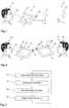
- Fig. 1shows a system comprising a device 10, for example a mobile device like a tablet PC or a mobile phone, and a light field camera 11 which may also be called plenoptic camera.
- the light field camera 11is located remote from the device 10.
- the light field camera 11is coupled to the device 10 via a connection 12 which may comprise any kind of suitable data communication, for example an Ethernet connection or a wireless connection like Bluetooth or WLAN.
- the light field camera 11may comprise an array camera for detecting a light field information of an environment 13.
- the environment 13comprises in this exemplary embodiment a circular object 14 and a star-shaped object 15.
- the objects 14, 15are located in a different distance to the light field camera 11, for example, the star 15 may be located in closer vicinity to the light field camera 11 than the circle 14.
- the device 10comprises a detecting unit 16, for example an infrared camera, a display unit 17 and an infrared illumination unit 18.
- a detecting unit 16for example an infrared camera
- a display unit 17On the display unit 17 the circle 14 and the star 15 are displayed based on the information received from the light field camera 11.
- a user 19is looking at the display unit 17 of the device 10.
- the user 19, especially the eyes of the user 19,are illuminated by the infrared illumination unit 18.
- the camera 16tracks the pupils of the user 19 to determine the direction 20 in which the user 19 is looking, thus determining a position on the display unit 17 at which the user is gazing. In the example shown in Fig. 1 , the user 19 is looking at the position where the circle 14 is displayed on the display unit 17.
- This gazing informationis used to generate a new image to be displayed on the display unit 17 based on the light field information provided by the light field camera 11.
- a focus planemay be set such that the circle 14 is in the focus.
- a color information, a contrast information or a brightness information of the circle 14may be adapted such that more details concerning color, contrast and brightness of the circle 14 are displayed on the display unit 17.
- a zooming into the imagemay be performed thus increasing the displayed size of the circle 14.
- the processing for generating the image information based on the light field information and the gaze informationmay be performed in either the light field camera 11 or the device 10.
- the gaze informationmay be sent from the device 10 to the light field camera 11.
- the light field camera 11detects the distance to the object gazed at from the information in the image grabbed by the light field camera 11. An image having a focus plane around that distance is generated and a two-dimensional image is created and sent to the device 10 and displayed on the display unit 17.
- the complete light field information captured by the light field camera 11may be sent from the light field camera 11 to the device 10, and the device 10 is responsible for detecting the distance at the gaze point, focusing around the distance, creating the image information and the displaying the image information.
- zoom in or out the image or to optimize high dynamic range informationfor example color, contrast and brightness.
- a zooming outmay be performed for example, when the user varies the position at which he is gazing rapidly.
- the focus planemay be set accordingly.
- Fig. 2shows two persons controlling the presentation of each other's light field camera images using gaze information.
- the image information displayed on the display unit 17 to the user 19is generated based on light field information captured by light field camera 11 capturing information of the environment 13 comprising the user 29.
- the gazing information of user 19is detected by camera 16.
- the image information displayed on the display unit 17is thus generated based on the light field information from light field camera 11 and the gaze information of user 19.
- gaze information of user 29is detected by camera 26 and the image information which is displayed on display unit 27 of device 20 is generated based on light field information captured by light field camera 21 capturing an environment of user 19, and based on the gaze information 30 of user 29.
- device 20comprises an illumination device 28 for illuminating the user 29 with infrared light to facilitate detecting the gaze information 30 with the camera 26.
- the camera 16 and the light field camera 21may be realized as separate cameras as shown in Fig. 2 . However, the camera 16 and the light field camera 21 may be combined in just one light field camera or array camera. In the latter case, at least some of the sub-cameras of the array camera have to be sensitive for infrared light in order to be used for the gaze tracking. This allows furthermore to capture light field information in low light conditions.
- Fig. 2The embodiment shown in Fig. 2 is not restricted to two persons, but can be generalized to a multiparty communication with more than two persons.
- Fig. 3shows exemplary method steps for generating an image information based on light field information.
- step 31light field information of an environment is captured.
- step 32a gaze information is detected.
- the gaze informationindicates a position where a user is gazing at while the user is looking on a display unit.
- step 33an image information is generated based on the light field information and the gaze information.
- step 34the image information is output on the display unit to the user.
- the gaze trackingmay be performed by any other devices, for example a camera tracking the pupils in the visible light range or a camera which is not arranged at the device 10 but which is arranged for example in glasses the user is wearing.
Landscapes
- Engineering & Computer Science (AREA)
- Multimedia (AREA)
- Signal Processing (AREA)
- General Engineering & Computer Science (AREA)
- Theoretical Computer Science (AREA)
- Human Computer Interaction (AREA)
- Physics & Mathematics (AREA)
- General Physics & Mathematics (AREA)
- User Interface Of Digital Computer (AREA)
- Position Input By Displaying (AREA)
- Studio Devices (AREA)
Description
- The present invention relates to a method for generating an image information, especially to a generation of an image information based on a light field information captured for example by a so-called light field camera or plenoptic camera. The present invention relates furthermore to a device implementing the method for generating an image information and to a light field camera.
- In conventional cameras, so-called digital cameras, an image of an environment or scene to be captured is reproduced on an image sensor, for example a CCD sensor or a CMOS sensor, via a lens. Data from the image sensor comprises for example a plurality of pixel data each representing a color and brightness of the image reproduced on the image sensor. The image data captured by the image sensor can be directly reproduced by a display to a user.
- A new type of camera which has been developed and researched in recent years is the so-called light field camera or plenoptic camera, which is one type of a so-called computational camera. In light field cameras, the image is not directly reproduced on the image sensor, such that essentially the output of the image sensor directly shows the captured scene, but light rays from the scene or environment are guided in light field cameras to an image sensor arrangement in an unconventional manner. For example, light rays originating from a single object in the scene to be captured may be guided to different locations remote from each other on the image sensor arrangement, which corresponds to viewing the object from different directions. To this end, for example a conical mirror may be arranged in front of a lens. In other implementations, an optic used for guiding light from a scene to be recorded to the image sensor arrangement may be variable, for example by varying geometric or radiometric properties. Furthermore, light field cameras may comprise an array of sub-cameras capturing the scene from different perspectives.
- Unlike conventional cameras, in light field cameras a more sophisticated processing of the data captured by the image sensors or the sub-cameras is necessary to provide the final image. On the other hand, in many cases there is a higher flexibility in setting parameters like focus plane of the final image. For example, by combining the images from the sub-cameras it is possible to achieve a number of attractive features, for example refocusing the image after capturing.
- In this context,
EP2 410 733 A2 discloses a camera system and a method of displaying photos. Photos captured using a light-field camera may be displayed on a display. The focus of the photo is adjusted to place an object at which the user is looking into focus. For example, depending on eye gaze of the user, the focus of the displayed photo will be adjusted to correspond to an object present at the location in the photo at which the user is looking. US 2011/0273466 A1 relates to a view-dependent rendering system. An area of interest to a viewer may be determined, for example, by identifying an area of an image as rendered on the display at which the viewer is gazing. For example, the viewer's eye movement may be tracked to determine a line of view from the viewer's eye to a region of the display. Upon determination of the area of interest the imaging property of the area of interest is adjusted, for example by focus, sharpness, white balance, dynamic range, resolution, brightness and tone mapping.US 2012/0127203 A1 relates to an image processing device which includes capture optics for capturing light-field information for a scene, and a display unit for providing a display of the scene to a viewer. A tracking unit tracks relative positions of a viewer's head and the display and the viewer's gaze to adjust the display based on the relative positions and to determine a region of interest on the display.US 2009/0256904 A1 relates to a system for 3-dimensional display of image data, which may be applied for example to a virtual 3D conference room. To support the use of goggles/earphones, multiple cameras and microphones are arrayed on walls to gain inputs from different vantages as data for computing 3D perspective for each participant from their location in the room. The user's pupils and their focus are tracked, and the system responds with detail imagery in the eyes' focus area and with less detail in the peripheral zone outside the eyes' focus area. This allows the optimum 3D perspective and focus for the user.US 2010/0321482 A1 relates to remotely controlling a setting of a video camera. Video from the video camera is displayed to a user using a video display. At least one eye of the user is imaged as the user is observing the video display. A change in an image of at least one eye of the user is measured over time, and an eye/head activity variable is calculated from the measured change in the image using an eye-tracker. The eye/head activity variable is translated into a camera control setting, and an actuator connected to the video camera is instructed to apply the camera control setting to the video camera using a processor.WO 2012/083989 A1 relates to a method of controlling audio recording using an electronic device. The electronic device comprises a microphone arrangement having a directivity pattern. A target direction relative to the electronic device is automatically determined in response to sensor data representing at least a portion of an area surrounding the electronic device. The microphone arrangement is automatically controlled in response to the determined target direction to adjust an angular orientation of the directivity pattern relative to the electronic device. The captured sensor data may have various forms depending on the specific implementation of the sensor. For example, the sensor may include an image sensor for recording a user's eye for determining an eye gaze direction.US 7,460,150 B1 discloses a system which may provide images from a location under surveillance to a video output device and/or recorder provided as part of a monitoring station. For instance, when the location comprises a public space, such as a train station, a gaze detection camera or unit may monitor the gazes of persons at the location. In response to determining that a majority of the persons at the location are looking at a particular area within that location, an imaging camera can be controlled to output imaged data that includes that particular area. Furthermore, an audio input may comprise a directional microphone. Information regarding the location of an area of interest within the scene determined using the direction of the gazes of persons at the location can be used to select a microphone within or near the area of interest, or to orient a directional microphone towards the area of interest.- However, controlling of the new flexibility and features of light field cameras requires intuitive control means to increase acceptance and user benefit of light field cameras. Therefore, there is a need for aiding a user to control new features of light field cameras.
- According to the present invention, this object is achieved by a method for generating an image information as defined in claim 1 and a system as defined in
claim 12. The dependent claims define preferred and advantageous embodiments of the invention. - According to an aspect of the present invention, a method for generating image information is provided. According to the method, a light field information of an environment or a scene is captured and a gaze information is detected, which indicates a position on a display at which a user is gazing. In other words, when the user is looking at a certain position on the display unit, this certain position is detected as the gaze information. Based on the light field information and the gaze information an image information is generated. Using the gaze information for generating the image information from the light field information allows for example setting a focus on a specific object in the environment, zooming in or out in the image, or optimizing so-called high dynamic range information like a contrast or a color range for a certain object or area in the image.
- Furthermore, an audio information of the environment is captured with an array microphone or an array of microphones, and an audio output based on the audio information and the position in the environment is generated. The array microphone captures comparable to the light field camera an acoustic field information of the environment. Thus, audio information originating from a certain position in the environment can be generated as the audio output wherein noise from other positions in the environment can be reduced. For example, when a crowd of people talking to each other is located in the environment, the user may gaze at a certain talking person. The gaze information indicates the position on the display unit where the person is displayed, and a corresponding position in the environment is determined. In the generated image information the head of the person may be focused. The audio output generated based on the audio information from the array microphone and the position in the environment includes therefore essentially audio information originating from the person, with noise from the talking other persons being reduced. Thus, a perceivability of the speech of the person can be increased.
- According to an embodiment, based on the light field information and the gaze information a two-dimensional or a three-dimensional image is rendered. Depending on the display which is used for displaying the image information to the user, a two-or three-dimensional image may be generated and displayed. Light field information allows to reconstruct an image information from different perspectives and therefore two-dimensional as well as three-dimensional or stereoscopic images can be reconstructed.
- According to a further embodiment, the light field information is captured as a four-dimensional light field information with a light field camera. Devices for capturing four-dimensional light field information may include a plurality of cameras arranged for example in an arc or in an array, or an optical system in which an array of microlenses is inserted in the optical path.
- According to another embodiment, the generated image information is displayed on the display unit to the user. By changing the position the user is looking at, a new gaze information can be generated and used for generating a correspondingly changed image information based on the light field information. The light field information may be updated continuously such that the generated image information is a live video of the environment captured. The light field information may be captured at a certain point in time, for example on a user demand, and the image information may be generated based on the light field information captured at this certain point in time. Thus, by changing the position on the display unit the user is looking at, different image information can be generated from the same light field information having different properties, for example a different focus plane or a different high dynamic range information.
- According to some embodiments, the image information is generated by determining a position in the environment which corresponds to the position on the display unit the user is gazing at. For example, a focus plane for generating the image information can be set according to a distance between the position in the environment and the light field camera. Furthermore, a scaled up or scaled down image information containing at least the position in the environment can be generated. Moreover, high dynamic range information like a color information, a contrast information or a brightness information of the image information can be adapted based on a color information, contrast information and brightness information, respectively, of the light field information at the position in the environment. For example, the display unit may have a lower color depth than the color depth provided in the light field information. When the user is looking at a certain position, an area around this certain position may have color information which comprises only a part of the color depth provided by the light field information. The color information of this area where the user is looking at may be generated in the image information using the full available color depth provided for the image information thus providing a more detailed color representation of this area to the user. Similarly, a more detailed contrast and brightness information may be provided in the image information and displayed to the user.
- According to an embodiment, a further gaze information is detected which indicates a further position on a further display unit at which a further user is gazing. Based on the light field information and the further gaze information a further image information is generated. The light field information comprises information from which different image information can be generated having for example a different focus plane. Thus, the light field information captured for example by a single light field camera can be provided to different display units of different users and for each user a specific image information can be generated depending on the gaze information of the respective user. For example, a first user may look at a first position on the display unit and the image information generated for the first user may be focused on an object at a corresponding first position in the environment. Based on the same light field information a second user may look at a second different position and a second image information may be generated focusing on an object at the position the second user is looking at. In other words, the same light field information can be provided to a plurality of users and for each user a specific image information can be generated taking into account the position the user is looking at.
- According to a further embodiment, a plurality of gaze information can be detected over a period of time. Each gaze information indicates a respective position on the display unit the user is gazing at. The gaze information is determined depending on the plurality of gaze information. For example, changing the focus in the generated image information may only be performed, when the user is looking at a certain position for a predetermined amount of time. Furthermore, a zooming into the image, i.e. a generation of a scaled up image information, may be performed, when the user looks continuously at the certain position for an even longer time. Moreover, a scaled down image information, i.e. a zoomed out image, may be generated, when the user is varying the position where he is looking at more frequently. Thus, the generation of the image information can be controlled intuitively by just looking at the generated image on the display unit.
- According to a further aspect of the present invention, a system comprising a light field camera for capturing a light field information of an environment, a microphone array for capturing an acoustic field information of the environment which is aligned with the light field information, a device located remote from the light field camera, and a data communication coupling the light field camera and the device is provided. The device, for example a mobile phone, a personal digital assistant, a mobile music player, a tablet computer, a laptop computer, a notebook computer or a navigation system, comprises an input for receiving a light field information of the environment via the data communication, and a display unit for displaying image information to a user. The device comprises furthermore a detecting unit for detecting a gaze information indicating a position on the display unit the user is gazing at. The device or the light filed camera comprises a processing unit which is configured to generate the image information based on the light field information and the gaze information, to determine a position in the environment which corresponds to the position on the display unit the user is gazing at, and to generate an audio output based on the acoustic field information and the position in the environment to include audio information originating from the position in the environment which corresponds to the position on the display unit at which the user is gazing. The system may be adapted to perform the above-described method and comprises therefore the above-described advantages.
- According to an embodiment, the detecting unit comprises an infrared camera. For detecting, where a user is looking or gazing at, a tracking of the pupils of the user may be tracked by a camera. Pupils provide a much better reflection of infrared light than of visible light. Therefore, a tracking of the pupils can be reliably performed using infrared light. The device may comprise additionally an infrared illumination source or a plurality of infrared illumination sources for illuminating the face and the eyes of the user. The most widely used current designs are video-based eye trackers. A camera focuses on one or both eyes and records their movement as the viewer looks at some kind of stimulus. Most modern eye-trackers use the centre of the pupil and infrared / near-infrared non-collimated light to create corneal reflections. The vector between the pupil centre and the corneal reflections can be used to compute the point of regard on surface or the gaze direction. A simple calibration procedure of the individual is usually needed before using the eye tracker. Two general types of eye tracking techniques are used: Bright Pupil and Dark Pupil. Their difference is based on the location of the illumination source with respect to the optics. If the illumination is coaxial with the optical path, then the eye acts as a retroreflector as the light reflects off the retina creating a bright pupil effect similar to red eye. If the illumination source is offset from the optical path, then the pupil appears dark because the retroreflection from the retina is directed away from the camera. Bright Pupil tracking creates greater iris/pupil contrast allowing for more robust eye tracking with all iris pigmentation and greatly reduces interference caused by eyelashes and other obscuring features. It also allows for tracking in lighting conditions ranging from total darkness to very bright. But bright pupil techniques are not effective for tracking outdoors as extraneous infrared sources interfere with monitoring.
- In some embodiments the detecting unit may comprise a light field camera. Thus, a light field information of the user and an environment around the user may be provided to other users facilitating for example video conferencing. The light field camera may be configured to detect light in or near the infrared spectrum. For example, one or more sub cameras of the light field camera may be sensitive to light in or near the infrared spectrum, whereas other sub cameras of the light field camera may be sensitive to light in the visible spectrum. Furthermore, one or more infrared illumination sources may be provided for illuminating the environment to be captured by the light field camera, e.g. an environment where the user is located. Therefore, the light field camera may be used for detecting where the user is looking or gazing at.
- As can be seen from the above-described device and light field camera, the processing for generating the image information based on the light field information and the gaze information may be performed in either the device or the light field camera. The processing may be performed in either the device or the light field camera depending on the available processing power or the communication bandwidth between the device and the light field camera.
- Although specific features described in the above summary and the following detailed description are described in connection with specific embodiments and aspects, it is to be understood that the features of the embodiments and aspects may be combined with each other unless specifically noted otherwise.
- The invention will now be described in more detail with reference to the accompanying drawings.
Fig. 1 shows a device and a light field camera according to embodiments of the present invention.Fig. 2 shows a device comprising a light field camera according to an embodiment of the present invention.Fig. 3 shows method steps according to an embodiment of the present invention.- In the following, exemplary embodiments of the invention will be described in more detail. It has to be understood that the features of the various exemplary embodiments described herein may be combined with each other unless specifically noted otherwise. Same reference signs in the various drawings and the following description refer to similar or identical components.
Fig. 1 shows a system comprising adevice 10, for example a mobile device like a tablet PC or a mobile phone, and alight field camera 11 which may also be called plenoptic camera. Thelight field camera 11 is located remote from thedevice 10. Thelight field camera 11 is coupled to thedevice 10 via aconnection 12 which may comprise any kind of suitable data communication, for example an Ethernet connection or a wireless connection like Bluetooth or WLAN. Thelight field camera 11 may comprise an array camera for detecting a light field information of anenvironment 13. Theenvironment 13 comprises in this exemplary embodiment acircular object 14 and a star-shapedobject 15. Theobjects light field camera 11, for example, thestar 15 may be located in closer vicinity to thelight field camera 11 than thecircle 14.- The
device 10 comprises a detectingunit 16, for example an infrared camera, adisplay unit 17 and aninfrared illumination unit 18. On thedisplay unit 17 thecircle 14 and thestar 15 are displayed based on the information received from thelight field camera 11. Auser 19 is looking at thedisplay unit 17 of thedevice 10. Theuser 19, especially the eyes of theuser 19, are illuminated by theinfrared illumination unit 18. Thecamera 16 tracks the pupils of theuser 19 to determine thedirection 20 in which theuser 19 is looking, thus determining a position on thedisplay unit 17 at which the user is gazing. In the example shown inFig. 1 , theuser 19 is looking at the position where thecircle 14 is displayed on thedisplay unit 17. This gazing information is used to generate a new image to be displayed on thedisplay unit 17 based on the light field information provided by thelight field camera 11. In the newly created image, a focus plane may be set such that thecircle 14 is in the focus. Furthermore, a color information, a contrast information or a brightness information of thecircle 14 may be adapted such that more details concerning color, contrast and brightness of thecircle 14 are displayed on thedisplay unit 17. Furthermore, for example when theuser 19 is gazing for at least a certain amount of time at thecircle 14, a zooming into the image may be performed thus increasing the displayed size of thecircle 14. - The processing for generating the image information based on the light field information and the gaze information may be performed in either the
light field camera 11 or thedevice 10. For example, the gaze information may be sent from thedevice 10 to thelight field camera 11. Thelight field camera 11 detects the distance to the object gazed at from the information in the image grabbed by thelight field camera 11. An image having a focus plane around that distance is generated and a two-dimensional image is created and sent to thedevice 10 and displayed on thedisplay unit 17. As an alternative, the complete light field information captured by thelight field camera 11 may be sent from thelight field camera 11 to thedevice 10, and thedevice 10 is responsible for detecting the distance at the gaze point, focusing around the distance, creating the image information and the displaying the image information. In addition to using the gaze to control the focus, it is possible to zoom in or out the image or to optimize high dynamic range information, for example color, contrast and brightness. A zooming out may be performed for example, when the user varies the position at which he is gazing rapidly. When changing the gaze to the star, the focus plane may be set accordingly. Naturally, it is also possible to generate the image information not only on the position the user is gazing at, but also based on an area or areas the user is gazing at for example also with varying gaze intensity over a period of time, which is then used when displaying the image on thedisplay unit 17. - Furthermore, it is also possible to control several remote light field cameras in the same way. It is also possible for multiple persons to control the same light field camera. Additionally, it is possible to control the direction of an array microphone using the gaze information in the same way. This may require some more information, concerning for example a placement and characteristics of the light field camera and the array microphone in order to align them. Again, it is possible to control the same remote array microphone by multiple users.
Fig. 2 shows two persons controlling the presentation of each other's light field camera images using gaze information. The image information displayed on thedisplay unit 17 to theuser 19 is generated based on light field information captured bylight field camera 11 capturing information of theenvironment 13 comprising theuser 29. The gazing information ofuser 19 is detected bycamera 16. The image information displayed on thedisplay unit 17 is thus generated based on the light field information fromlight field camera 11 and the gaze information ofuser 19. In the same way, gaze information ofuser 29 is detected bycamera 26 and the image information which is displayed ondisplay unit 27 ofdevice 20 is generated based on light field information captured bylight field camera 21 capturing an environment ofuser 19, and based on thegaze information 30 ofuser 29. Additionally,device 20 comprises anillumination device 28 for illuminating theuser 29 with infrared light to facilitate detecting thegaze information 30 with thecamera 26.- The
camera 16 and thelight field camera 21 may be realized as separate cameras as shown inFig. 2 . However, thecamera 16 and thelight field camera 21 may be combined in just one light field camera or array camera. In the latter case, at least some of the sub-cameras of the array camera have to be sensitive for infrared light in order to be used for the gaze tracking. This allows furthermore to capture light field information in low light conditions. - The embodiment shown in
Fig. 2 is not restricted to two persons, but can be generalized to a multiparty communication with more than two persons. Fig. 3 shows exemplary method steps for generating an image information based on light field information. Instep 31 light field information of an environment is captured. In step 32 a gaze information is detected. The gaze information indicates a position where a user is gazing at while the user is looking on a display unit. Instep 33 an image information is generated based on the light field information and the gaze information. Instep 34 the image information is output on the display unit to the user.- While exemplary embodiments have been described above, various modifications may be implemented in other embodiments. For example, instead of a light field camera any other kind of computational camera may be used. Furthermore, the gaze tracking may be performed by any other devices, for example a camera tracking the pupils in the visible light range or a camera which is not arranged at the
device 10 but which is arranged for example in glasses the user is wearing.
Claims (12)
- A method for generating an image information, the method comprising:- capturing (31) a light field information of an environment (13) with a light field camera (11),- detecting (32) a gaze information indicating a position on a display unit (17) a user (19) is gazing at, wherein a device (10) comprising the display unit (17) is located remote from the light field camera (11),- communicating at least one of the light field information and the gaze information via a data communication between the light field camera (11) and the device (10),- generating (33) an image information based on the light field information and the gaze information, wherein generating (33) the image information comprises determining a position in the environment (13) which corresponds to the position on the display unit (17) the user (19) is gazing at,- capturing an audio information of the environment (13) with a microphone array, the microphone array capturing an acoustic field information of the environment which is aligned with the light field information, and- generating an audio output based on the acoustic field information and the position in the environment (13) to include audio information originating from the position in the environment which corresponds to the position on the display unit (17) at which the user is gazing.
- The method according to claim 1, wherein generating (33) the image information comprises rendering a two-dimensional or a three-dimensional image based on the light field information and the gaze information.
- The method according to claim 1 or 2, wherein capturing (31) the light field information comprises capturing a four-dimensional light field information with the light field camera (11).
- The method according to any one of the preceding claims, further comprising:- displaying (34) the generated image information on the display unit (17) to the user (19).
- The method according to any one of the preceding claims, wherein generating (33) the image information comprises at least one method step of a group comprising:- setting a focus plane for generating the image information according to a distance of the position in the environment (13),- generating a scaled up or scaled down image information containing at least the position in the environment (13),- adapting a color information of the image information based on a color information of the light field information at the position in the environment (13),- adapting a contrast information of the image information based on a contrast information of the light field information at the position in the environment (13), and- adapting a brightness information of the image information based on a brightness information of the light field information at the position in the environment (13).
- The method according to any one of the preceding claims, further comprising:- detecting a further gaze information indicating a further position on a further display unit a further user is gazing at,- generating a further image information based on the light field information and the further gaze information.
- The method according to any one of the preceding claims, wherein detecting (32) the gaze information comprises:- detecting a plurality of gaze information over a period of time, each gaze information of the plurality of gaze information indicating a respective position on the display unit (17) the user (19) is gazing at,- determining the gaze information depending on the plurality of gaze information.
- A system comprising:- a light field camera (11) for capturing (31) a light field information of an environment (13),- a microphone array for capturing an acoustic field information of the environment (13) which is aligned with the light field information,- a device (10) located remote from the light field camera (11), and- a data communication coupling the light field camera (11) and the device (10), the device (10) comprising:- an input for receiving the light field information of the environment (13) via the data communication,- a display unit (17) for displaying image information to a user (19), and- a detecting unit (16) for detecting a gaze information indicating a position on the display unit (17) the user (19) is gazing at, and- a processing unit comprised in the light field camera (11) or the device (10) and configuredto generate an image information based on the light field information and the gaze information,to determine a position in the environment (13) which corresponds to the position on the display unit (17) the user (19) is gazing at, andto generate an audio output based on the acoustic field information and the position in the environment (13) to include audio information originating from the position in the environment which corresponds to the position on the display unit (17) at which the user is gazing.
- The system according to claim 8, wherein the detecting unit (16) comprises an infrared camera.
- The system according to claim 8 or 9, wherein the detecting unit comprises a light field camera.
- The system according to any one of claims 8-10, wherein the processing unit is configured to perform the method according to any one of the claims 1-7.
- The system according to any one of claims 8-11, wherein the device (10) comprises at least one device of a group consisting of a mobile phone, a personal digital assistant, a mobile music player, a tablet computer, a laptop computer, a notebook computer, and a navigation system.
Priority Applications (2)
| Application Number | Priority Date | Filing Date | Title |
|---|---|---|---|
| EP12007049.5AEP2720464B1 (en) | 2012-10-11 | 2012-10-11 | Generating image information |
| US14/052,150US20140104392A1 (en) | 2012-10-11 | 2013-10-11 | Generating image information |
Applications Claiming Priority (1)
| Application Number | Priority Date | Filing Date | Title |
|---|---|---|---|
| EP12007049.5AEP2720464B1 (en) | 2012-10-11 | 2012-10-11 | Generating image information |
Publications (2)
| Publication Number | Publication Date |
|---|---|
| EP2720464A1 EP2720464A1 (en) | 2014-04-16 |
| EP2720464B1true EP2720464B1 (en) | 2018-01-10 |
Family
ID=47080158
Family Applications (1)
| Application Number | Title | Priority Date | Filing Date |
|---|---|---|---|
| EP12007049.5ANot-in-forceEP2720464B1 (en) | 2012-10-11 | 2012-10-11 | Generating image information |
Country Status (2)
| Country | Link |
|---|---|
| US (1) | US20140104392A1 (en) |
| EP (1) | EP2720464B1 (en) |
Families Citing this family (15)
| Publication number | Priority date | Publication date | Assignee | Title |
|---|---|---|---|---|
| US10921885B2 (en)* | 2003-03-03 | 2021-02-16 | Arjuna Indraeswaran Rajasingham | Occupant supports and virtual visualization and navigation |
| US10356364B2 (en)* | 2013-09-10 | 2019-07-16 | Minerva Project, Inc. | Registering and displaying visual attention metadata in a web video conferencing and seminar system |
| US9521170B2 (en) | 2014-04-22 | 2016-12-13 | Minerva Project, Inc. | Participation queue system and method for online video conferencing |
| EP3289401B1 (en)* | 2015-04-30 | 2023-07-26 | Google LLC | Virtual eyeglass set for viewing actual scene that corrects for different location of lenses than eyes |
| EP3112922A1 (en)* | 2015-06-30 | 2017-01-04 | Thomson Licensing | A gaze tracking device and a head mounted device embedding said gaze tracking device |
| KR102415502B1 (en)* | 2015-08-07 | 2022-07-01 | 삼성전자주식회사 | Method and apparatus of light filed rendering for plurality of user |
| EP3151535A1 (en) | 2015-09-29 | 2017-04-05 | Thomson Licensing | Plenoptic camera having an array of sensors for generating digital images and method of capturing an image using a plenoptic camera |
| EP3151534A1 (en) | 2015-09-29 | 2017-04-05 | Thomson Licensing | Method of refocusing images captured by a plenoptic camera and audio based refocusing image system |
| EP3235478A1 (en) | 2016-04-18 | 2017-10-25 | Universität Wien | Protective eyewear |
| US9832372B1 (en)* | 2017-03-18 | 2017-11-28 | Jerry L. Conway, Sr. | Dynamic vediotelphony systems and methods of using the same |
| CN106954013B (en)* | 2017-04-19 | 2023-06-20 | 中国科学技术大学 | A compact high-resolution light-field camera with dual optical path imaging |
| US11221669B2 (en)* | 2017-12-20 | 2022-01-11 | Microsoft Technology Licensing, Llc | Non-verbal engagement of a virtual assistant |
| JP7588958B2 (en)* | 2020-02-19 | 2024-11-25 | キヤノン株式会社 | Electronics |
| US11620000B1 (en)* | 2022-03-31 | 2023-04-04 | Microsoft Technology Licensing, Llc | Controlled invocation of a precision input mode |
| US12368837B2 (en) | 2022-04-26 | 2025-07-22 | Boe Technology Group Co., Ltd. | Method and system for transmitting light field data and light field communication apparatus |
Citations (2)
| Publication number | Priority date | Publication date | Assignee | Title |
|---|---|---|---|---|
| US7460150B1 (en)* | 2005-03-14 | 2008-12-02 | Avaya Inc. | Using gaze detection to determine an area of interest within a scene |
| WO2012083989A1 (en)* | 2010-12-22 | 2012-06-28 | Sony Ericsson Mobile Communications Ab | Method of controlling audio recording and electronic device |
Family Cites Families (9)
| Publication number | Priority date | Publication date | Assignee | Title |
|---|---|---|---|---|
| US8130260B2 (en)* | 2005-11-09 | 2012-03-06 | Johns Hopkins University | System and method for 3-dimensional display of image data |
| US8274402B1 (en)* | 2008-01-24 | 2012-09-25 | LDARtools, Inc. | Data collection process for optical leak detection |
| US8253778B2 (en)* | 2008-03-21 | 2012-08-28 | Takahashi Atsushi | Three-dimensional digital magnifier operation supporting system |
| US8155479B2 (en)* | 2008-03-28 | 2012-04-10 | Intuitive Surgical Operations Inc. | Automated panning and digital zooming for robotic surgical systems |
| US20100321482A1 (en)* | 2009-06-17 | 2010-12-23 | Lc Technologies Inc. | Eye/head controls for camera pointing |
| US20110273466A1 (en)* | 2010-05-10 | 2011-11-10 | Canon Kabushiki Kaisha | View-dependent rendering system with intuitive mixed reality |
| US20120019703A1 (en)* | 2010-07-22 | 2012-01-26 | Thorn Karl Ola | Camera system and method of displaying photos |
| US20120127203A1 (en)* | 2010-11-18 | 2012-05-24 | Canon Kabushiki Kaisha | Mixed reality display |
| EP2817955B1 (en)* | 2012-02-21 | 2018-04-11 | FotoNation Cayman Limited | Systems and methods for the manipulation of captured light field image data |
- 2012
- 2012-10-11EPEP12007049.5Apatent/EP2720464B1/ennot_activeNot-in-force
- 2013
- 2013-10-11USUS14/052,150patent/US20140104392A1/ennot_activeAbandoned
Patent Citations (2)
| Publication number | Priority date | Publication date | Assignee | Title |
|---|---|---|---|---|
| US7460150B1 (en)* | 2005-03-14 | 2008-12-02 | Avaya Inc. | Using gaze detection to determine an area of interest within a scene |
| WO2012083989A1 (en)* | 2010-12-22 | 2012-06-28 | Sony Ericsson Mobile Communications Ab | Method of controlling audio recording and electronic device |
Also Published As
| Publication number | Publication date |
|---|---|
| US20140104392A1 (en) | 2014-04-17 |
| EP2720464A1 (en) | 2014-04-16 |
Similar Documents
| Publication | Publication Date | Title |
|---|---|---|
| EP2720464B1 (en) | Generating image information | |
| US11388388B2 (en) | System and method for processing three dimensional images | |
| US9344612B2 (en) | Non-interference field-of-view support apparatus for a panoramic facial sensor | |
| US20230141039A1 (en) | Immersive displays | |
| CN103869468B (en) | Information processing apparatus | |
| US20220109822A1 (en) | Multi-sensor camera systems, devices, and methods for providing image pan, tilt, and zoom functionality | |
| CN109952759A (en) | Improved method and system for the video conference with HMD | |
| US12028419B1 (en) | Systems and methods for predictively downloading volumetric data | |
| US20250315974A1 (en) | Self-tracked controller | |
| JP2015023512A (en) | Imaging apparatus, imaging method and imaging program for imaging apparatus | |
| EP3945401B1 (en) | Gaze tracking system and method | |
| GB2597917A (en) | Gaze tracking method and apparatus | |
| US20210382316A1 (en) | Gaze tracking apparatus and systems | |
| US20240073564A1 (en) | Region of interest sampling and retrieval for artificial reality systems | |
| JP2021068296A (en) | Information processing device, head-mounted display, and user operation processing method | |
| US20230308753A1 (en) | Camera system for focusing on and tracking objects | |
| GB2598953A (en) | Head mounted display |
Legal Events
| Date | Code | Title | Description |
|---|---|---|---|
| PUAI | Public reference made under article 153(3) epc to a published international application that has entered the european phase | Free format text:ORIGINAL CODE: 0009012 | |
| AK | Designated contracting states | Kind code of ref document:A1 Designated state(s):AL AT BE BG CH CY CZ DE DK EE ES FI FR GB GR HR HU IE IS IT LI LT LU LV MC MK MT NL NO PL PT RO RS SE SI SK SM TR | |
| AX | Request for extension of the european patent | Extension state:BA ME | |
| RBV | Designated contracting states (corrected) | Designated state(s):AL AT BE BG CH CY CZ DE DK EE ES FI FR GB GR HR HU IE IS IT LI LT LU LV MC MK MT NL NO PL PT RO RS SE SI SK SM TR | |
| 17P | Request for examination filed | Effective date:20140828 | |
| 17Q | First examination report despatched | Effective date:20160523 | |
| GRAP | Despatch of communication of intention to grant a patent | Free format text:ORIGINAL CODE: EPIDOSNIGR1 | |
| INTG | Intention to grant announced | Effective date:20170731 | |
| GRAS | Grant fee paid | Free format text:ORIGINAL CODE: EPIDOSNIGR3 | |
| GRAA | (expected) grant | Free format text:ORIGINAL CODE: 0009210 | |
| AK | Designated contracting states | Kind code of ref document:B1 Designated state(s):AL AT BE BG CH CY CZ DE DK EE ES FI FR GB GR HR HU IE IS IT LI LT LU LV MC MK MT NL NO PL PT RO RS SE SI SK SM TR | |
| RAP1 | Party data changed (applicant data changed or rights of an application transferred) | Owner name:SONY MOBILE COMMUNICATIONS INC. | |
| REG | Reference to a national code | Ref country code:CH Ref legal event code:EP Ref country code:AT Ref legal event code:REF Ref document number:963649 Country of ref document:AT Kind code of ref document:T Effective date:20180115 | |
| REG | Reference to a national code | Ref country code:IE Ref legal event code:FG4D | |
| REG | Reference to a national code | Ref country code:DE Ref legal event code:R096 Ref document number:602012041742 Country of ref document:DE | |
| REG | Reference to a national code | Ref country code:NL Ref legal event code:FP | |
| REG | Reference to a national code | Ref country code:AT Ref legal event code:MK05 Ref document number:963649 Country of ref document:AT Kind code of ref document:T Effective date:20180110 | |
| PG25 | Lapsed in a contracting state [announced via postgrant information from national office to epo] | Ref country code:HR Free format text:LAPSE BECAUSE OF FAILURE TO SUBMIT A TRANSLATION OF THE DESCRIPTION OR TO PAY THE FEE WITHIN THE PRESCRIBED TIME-LIMIT Effective date:20180110 Ref country code:NO Free format text:LAPSE BECAUSE OF FAILURE TO SUBMIT A TRANSLATION OF THE DESCRIPTION OR TO PAY THE FEE WITHIN THE PRESCRIBED TIME-LIMIT Effective date:20180410 Ref country code:CY Free format text:LAPSE BECAUSE OF FAILURE TO SUBMIT A TRANSLATION OF THE DESCRIPTION OR TO PAY THE FEE WITHIN THE PRESCRIBED TIME-LIMIT Effective date:20180110 Ref country code:FI Free format text:LAPSE BECAUSE OF FAILURE TO SUBMIT A TRANSLATION OF THE DESCRIPTION OR TO PAY THE FEE WITHIN THE PRESCRIBED TIME-LIMIT Effective date:20180110 Ref country code:ES Free format text:LAPSE BECAUSE OF FAILURE TO SUBMIT A TRANSLATION OF THE DESCRIPTION OR TO PAY THE FEE WITHIN THE PRESCRIBED TIME-LIMIT Effective date:20180110 Ref country code:LT Free format text:LAPSE BECAUSE OF FAILURE TO SUBMIT A TRANSLATION OF THE DESCRIPTION OR TO PAY THE FEE WITHIN THE PRESCRIBED TIME-LIMIT Effective date:20180110 | |
| PG25 | Lapsed in a contracting state [announced via postgrant information from national office to epo] | Ref country code:PL Free format text:LAPSE BECAUSE OF FAILURE TO SUBMIT A TRANSLATION OF THE DESCRIPTION OR TO PAY THE FEE WITHIN THE PRESCRIBED TIME-LIMIT Effective date:20180110 Ref country code:RS Free format text:LAPSE BECAUSE OF FAILURE TO SUBMIT A TRANSLATION OF THE DESCRIPTION OR TO PAY THE FEE WITHIN THE PRESCRIBED TIME-LIMIT Effective date:20180110 Ref country code:AT Free format text:LAPSE BECAUSE OF FAILURE TO SUBMIT A TRANSLATION OF THE DESCRIPTION OR TO PAY THE FEE WITHIN THE PRESCRIBED TIME-LIMIT Effective date:20180110 Ref country code:SE Free format text:LAPSE BECAUSE OF FAILURE TO SUBMIT A TRANSLATION OF THE DESCRIPTION OR TO PAY THE FEE WITHIN THE PRESCRIBED TIME-LIMIT Effective date:20180110 Ref country code:LV Free format text:LAPSE BECAUSE OF FAILURE TO SUBMIT A TRANSLATION OF THE DESCRIPTION OR TO PAY THE FEE WITHIN THE PRESCRIBED TIME-LIMIT Effective date:20180110 Ref country code:GR Free format text:LAPSE BECAUSE OF FAILURE TO SUBMIT A TRANSLATION OF THE DESCRIPTION OR TO PAY THE FEE WITHIN THE PRESCRIBED TIME-LIMIT Effective date:20180411 Ref country code:BG Free format text:LAPSE BECAUSE OF FAILURE TO SUBMIT A TRANSLATION OF THE DESCRIPTION OR TO PAY THE FEE WITHIN THE PRESCRIBED TIME-LIMIT Effective date:20180410 Ref country code:IS Free format text:LAPSE BECAUSE OF FAILURE TO SUBMIT A TRANSLATION OF THE DESCRIPTION OR TO PAY THE FEE WITHIN THE PRESCRIBED TIME-LIMIT Effective date:20180510 | |
| REG | Reference to a national code | Ref country code:DE Ref legal event code:R097 Ref document number:602012041742 Country of ref document:DE | |
| PG25 | Lapsed in a contracting state [announced via postgrant information from national office to epo] | Ref country code:AL Free format text:LAPSE BECAUSE OF FAILURE TO SUBMIT A TRANSLATION OF THE DESCRIPTION OR TO PAY THE FEE WITHIN THE PRESCRIBED TIME-LIMIT Effective date:20180110 Ref country code:EE Free format text:LAPSE BECAUSE OF FAILURE TO SUBMIT A TRANSLATION OF THE DESCRIPTION OR TO PAY THE FEE WITHIN THE PRESCRIBED TIME-LIMIT Effective date:20180110 Ref country code:IT Free format text:LAPSE BECAUSE OF FAILURE TO SUBMIT A TRANSLATION OF THE DESCRIPTION OR TO PAY THE FEE WITHIN THE PRESCRIBED TIME-LIMIT Effective date:20180110 Ref country code:RO Free format text:LAPSE BECAUSE OF FAILURE TO SUBMIT A TRANSLATION OF THE DESCRIPTION OR TO PAY THE FEE WITHIN THE PRESCRIBED TIME-LIMIT Effective date:20180110 | |
| PLBE | No opposition filed within time limit | Free format text:ORIGINAL CODE: 0009261 | |
| STAA | Information on the status of an ep patent application or granted ep patent | Free format text:STATUS: NO OPPOSITION FILED WITHIN TIME LIMIT | |
| PG25 | Lapsed in a contracting state [announced via postgrant information from national office to epo] | Ref country code:CZ Free format text:LAPSE BECAUSE OF FAILURE TO SUBMIT A TRANSLATION OF THE DESCRIPTION OR TO PAY THE FEE WITHIN THE PRESCRIBED TIME-LIMIT Effective date:20180110 Ref country code:SK Free format text:LAPSE BECAUSE OF FAILURE TO SUBMIT A TRANSLATION OF THE DESCRIPTION OR TO PAY THE FEE WITHIN THE PRESCRIBED TIME-LIMIT Effective date:20180110 Ref country code:DK Free format text:LAPSE BECAUSE OF FAILURE TO SUBMIT A TRANSLATION OF THE DESCRIPTION OR TO PAY THE FEE WITHIN THE PRESCRIBED TIME-LIMIT Effective date:20180110 Ref country code:SM Free format text:LAPSE BECAUSE OF FAILURE TO SUBMIT A TRANSLATION OF THE DESCRIPTION OR TO PAY THE FEE WITHIN THE PRESCRIBED TIME-LIMIT Effective date:20180110 | |
| 26N | No opposition filed | Effective date:20181011 | |
| RIC2 | Information provided on ipc code assigned after grant | Ipc:H04N 5/232 20060101ALI20130412BHEP Ipc:H04N 13/04 20181130ALI20130412BHEP Ipc:H04N 5/225 20060101ALI20130412BHEP Ipc:H04N 13/02 20181130AFI20130412BHEP Ipc:G06F 3/01 20060101ALI20130412BHEP | |
| REG | Reference to a national code | Ref country code:CH Ref legal event code:PK Free format text:BERICHTIGUNGEN | |
| REG | Reference to a national code | Ref country code:CH Ref legal event code:PK Free format text:BERICHTIGUNGEN | |
| RIC2 | Information provided on ipc code assigned after grant | Ipc:H04N 13/04 20060101ALI20130412BHEP Ipc:H04N 13/02 20060101AFI20130412BHEP Ipc:H04N 5/225 20060101ALI20130412BHEP Ipc:G06F 3/01 20060101ALI20130412BHEP Ipc:H04N 5/232 20060101ALI20130412BHEP | |
| PG25 | Lapsed in a contracting state [announced via postgrant information from national office to epo] | Ref country code:SI Free format text:LAPSE BECAUSE OF FAILURE TO SUBMIT A TRANSLATION OF THE DESCRIPTION OR TO PAY THE FEE WITHIN THE PRESCRIBED TIME-LIMIT Effective date:20180110 | |
| REG | Reference to a national code | Ref country code:CH Ref legal event code:PL | |
| GBPC | Gb: european patent ceased through non-payment of renewal fee | Effective date:20181011 | |
| REG | Reference to a national code | Ref country code:BE Ref legal event code:MM Effective date:20181031 | |
| PG25 | Lapsed in a contracting state [announced via postgrant information from national office to epo] | Ref country code:MC Free format text:LAPSE BECAUSE OF FAILURE TO SUBMIT A TRANSLATION OF THE DESCRIPTION OR TO PAY THE FEE WITHIN THE PRESCRIBED TIME-LIMIT Effective date:20180110 Ref country code:LU Free format text:LAPSE BECAUSE OF NON-PAYMENT OF DUE FEES Effective date:20181011 | |
| REG | Reference to a national code | Ref country code:IE Ref legal event code:MM4A | |
| PG25 | Lapsed in a contracting state [announced via postgrant information from national office to epo] | Ref country code:FR Free format text:LAPSE BECAUSE OF NON-PAYMENT OF DUE FEES Effective date:20181031 Ref country code:BE Free format text:LAPSE BECAUSE OF NON-PAYMENT OF DUE FEES Effective date:20181031 Ref country code:CH Free format text:LAPSE BECAUSE OF NON-PAYMENT OF DUE FEES Effective date:20181031 Ref country code:LI Free format text:LAPSE BECAUSE OF NON-PAYMENT OF DUE FEES Effective date:20181031 | |
| PG25 | Lapsed in a contracting state [announced via postgrant information from national office to epo] | Ref country code:IE Free format text:LAPSE BECAUSE OF NON-PAYMENT OF DUE FEES Effective date:20181011 Ref country code:GB Free format text:LAPSE BECAUSE OF NON-PAYMENT OF DUE FEES Effective date:20181011 | |
| PG25 | Lapsed in a contracting state [announced via postgrant information from national office to epo] | Ref country code:MT Free format text:LAPSE BECAUSE OF NON-PAYMENT OF DUE FEES Effective date:20181011 | |
| PG25 | Lapsed in a contracting state [announced via postgrant information from national office to epo] | Ref country code:TR Free format text:LAPSE BECAUSE OF FAILURE TO SUBMIT A TRANSLATION OF THE DESCRIPTION OR TO PAY THE FEE WITHIN THE PRESCRIBED TIME-LIMIT Effective date:20180110 | |
| PG25 | Lapsed in a contracting state [announced via postgrant information from national office to epo] | Ref country code:PT Free format text:LAPSE BECAUSE OF FAILURE TO SUBMIT A TRANSLATION OF THE DESCRIPTION OR TO PAY THE FEE WITHIN THE PRESCRIBED TIME-LIMIT Effective date:20180110 | |
| PG25 | Lapsed in a contracting state [announced via postgrant information from national office to epo] | Ref country code:HU Free format text:LAPSE BECAUSE OF FAILURE TO SUBMIT A TRANSLATION OF THE DESCRIPTION OR TO PAY THE FEE WITHIN THE PRESCRIBED TIME-LIMIT; INVALID AB INITIO Effective date:20121011 Ref country code:MK Free format text:LAPSE BECAUSE OF NON-PAYMENT OF DUE FEES Effective date:20180110 | |
| PGFP | Annual fee paid to national office [announced via postgrant information from national office to epo] | Ref country code:NL Payment date:20201015 Year of fee payment:9 | |
| PGFP | Annual fee paid to national office [announced via postgrant information from national office to epo] | Ref country code:DE Payment date:20200929 Year of fee payment:9 | |
| REG | Reference to a national code | Ref country code:DE Ref legal event code:R119 Ref document number:602012041742 Country of ref document:DE | |
| REG | Reference to a national code | Ref country code:NL Ref legal event code:MM Effective date:20211101 | |
| PG25 | Lapsed in a contracting state [announced via postgrant information from national office to epo] | Ref country code:NL Free format text:LAPSE BECAUSE OF NON-PAYMENT OF DUE FEES Effective date:20211101 Ref country code:DE Free format text:LAPSE BECAUSE OF NON-PAYMENT OF DUE FEES Effective date:20220503 |