EP2719484B1 - Component for turbomachine - Google Patents
Component for turbomachineDownload PDFInfo
- Publication number
- EP2719484B1 EP2719484B1EP12188332.6AEP12188332AEP2719484B1EP 2719484 B1EP2719484 B1EP 2719484B1EP 12188332 AEP12188332 AEP 12188332AEP 2719484 B1EP2719484 B1EP 2719484B1
- Authority
- EP
- European Patent Office
- Prior art keywords
- component
- base body
- main part
- component section
- section
- Prior art date
- Legal status (The legal status is an assumption and is not a legal conclusion. Google has not performed a legal analysis and makes no representation as to the accuracy of the status listed.)
- Active
Links
- 239000000463materialSubstances0.000claimsdescription72
- 238000005245sinteringMethods0.000claimsdescription10
- 239000006185dispersionSubstances0.000claimsdescription8
- 239000000843powderSubstances0.000claimsdescription8
- 238000002844meltingMethods0.000claimsdescription5
- 230000008018meltingEffects0.000claimsdescription5
- 239000012783reinforcing fiberSubstances0.000claimsdescription5
- 239000000919ceramicSubstances0.000description28
- 238000004519manufacturing processMethods0.000description26
- 239000010410layerSubstances0.000description25
- 238000000034methodMethods0.000description16
- 238000001816coolingMethods0.000description8
- 239000002131composite materialSubstances0.000description6
- 238000005096rolling processMethods0.000description5
- 239000000126substanceSubstances0.000description5
- 239000000835fiberSubstances0.000description4
- 229910001092metal group alloyInorganic materials0.000description4
- 239000011858nanopowderSubstances0.000description4
- 238000000576coating methodMethods0.000description3
- 230000006378damageEffects0.000description3
- 239000002184metalSubstances0.000description3
- 239000007769metal materialSubstances0.000description3
- 230000007704transitionEffects0.000description3
- 239000000654additiveSubstances0.000description2
- 230000000996additive effectEffects0.000description2
- 239000011230binding agentSubstances0.000description2
- 239000011248coating agentSubstances0.000description2
- 238000007906compressionMethods0.000description2
- 238000010276constructionMethods0.000description2
- 230000007797corrosionEffects0.000description2
- 238000005260corrosionMethods0.000description2
- 230000000694effectsEffects0.000description2
- 230000003628erosive effectEffects0.000description2
- 230000002349favourable effectEffects0.000description2
- 230000003647oxidationEffects0.000description2
- 238000007254oxidation reactionMethods0.000description2
- 239000011241protective layerSubstances0.000description2
- 230000035882stressEffects0.000description2
- 229920000049Carbon (fiber)Polymers0.000description1
- 239000000443aerosolSubstances0.000description1
- 238000004873anchoringMethods0.000description1
- 239000004760aramidSubstances0.000description1
- 229920006231aramid fiberPolymers0.000description1
- 238000009412basement excavationMethods0.000description1
- 230000015572biosynthetic processEffects0.000description1
- 210000000746body regionAnatomy0.000description1
- 239000004917carbon fiberSubstances0.000description1
- 229910010293ceramic materialInorganic materials0.000description1
- 238000005056compactionMethods0.000description1
- 230000000052comparative effectEffects0.000description1
- 238000013016dampingMethods0.000description1
- 230000001419dependent effectEffects0.000description1
- 230000008021depositionEffects0.000description1
- 238000005137deposition processMethods0.000description1
- 238000009826distributionMethods0.000description1
- 239000012530fluidSubstances0.000description1
- 239000003365glass fiberSubstances0.000description1
- 239000007788liquidSubstances0.000description1
- 230000002787reinforcementEffects0.000description1
- 238000007789sealingMethods0.000description1
- 230000011218segmentationEffects0.000description1
- 230000035939shockEffects0.000description1
- 239000007921spraySubstances0.000description1
- 238000003860storageMethods0.000description1
- 230000008646thermal stressEffects0.000description1
Images


Classifications
- B—PERFORMING OPERATIONS; TRANSPORTING
- B22—CASTING; POWDER METALLURGY
- B22F—WORKING METALLIC POWDER; MANUFACTURE OF ARTICLES FROM METALLIC POWDER; MAKING METALLIC POWDER; APPARATUS OR DEVICES SPECIALLY ADAPTED FOR METALLIC POWDER
- B22F5/00—Manufacture of workpieces or articles from metallic powder characterised by the special shape of the product
- B22F5/009—Manufacture of workpieces or articles from metallic powder characterised by the special shape of the product of turbine components other than turbine blades
- B—PERFORMING OPERATIONS; TRANSPORTING
- B22—CASTING; POWDER METALLURGY
- B22F—WORKING METALLIC POWDER; MANUFACTURE OF ARTICLES FROM METALLIC POWDER; MAKING METALLIC POWDER; APPARATUS OR DEVICES SPECIALLY ADAPTED FOR METALLIC POWDER
- B22F10/00—Additive manufacturing of workpieces or articles from metallic powder
- B22F10/20—Direct sintering or melting
- B—PERFORMING OPERATIONS; TRANSPORTING
- B22—CASTING; POWDER METALLURGY
- B22F—WORKING METALLIC POWDER; MANUFACTURE OF ARTICLES FROM METALLIC POWDER; MAKING METALLIC POWDER; APPARATUS OR DEVICES SPECIALLY ADAPTED FOR METALLIC POWDER
- B22F5/00—Manufacture of workpieces or articles from metallic powder characterised by the special shape of the product
- B22F5/04—Manufacture of workpieces or articles from metallic powder characterised by the special shape of the product of turbine blades
- B—PERFORMING OPERATIONS; TRANSPORTING
- B22—CASTING; POWDER METALLURGY
- B22F—WORKING METALLIC POWDER; MANUFACTURE OF ARTICLES FROM METALLIC POWDER; MAKING METALLIC POWDER; APPARATUS OR DEVICES SPECIALLY ADAPTED FOR METALLIC POWDER
- B22F5/00—Manufacture of workpieces or articles from metallic powder characterised by the special shape of the product
- B22F5/08—Manufacture of workpieces or articles from metallic powder characterised by the special shape of the product of toothed articles, e.g. gear wheels; of cam discs
- B—PERFORMING OPERATIONS; TRANSPORTING
- B22—CASTING; POWDER METALLURGY
- B22F—WORKING METALLIC POWDER; MANUFACTURE OF ARTICLES FROM METALLIC POWDER; MAKING METALLIC POWDER; APPARATUS OR DEVICES SPECIALLY ADAPTED FOR METALLIC POWDER
- B22F7/00—Manufacture of composite layers, workpieces, or articles, comprising metallic powder, by sintering the powder, with or without compacting wherein at least one part is obtained by sintering or compression
- B22F7/06—Manufacture of composite layers, workpieces, or articles, comprising metallic powder, by sintering the powder, with or without compacting wherein at least one part is obtained by sintering or compression of composite workpieces or articles from parts, e.g. to form tipped tools
- B22F7/062—Manufacture of composite layers, workpieces, or articles, comprising metallic powder, by sintering the powder, with or without compacting wherein at least one part is obtained by sintering or compression of composite workpieces or articles from parts, e.g. to form tipped tools involving the connection or repairing of preformed parts
- F—MECHANICAL ENGINEERING; LIGHTING; HEATING; WEAPONS; BLASTING
- F01—MACHINES OR ENGINES IN GENERAL; ENGINE PLANTS IN GENERAL; STEAM ENGINES
- F01D—NON-POSITIVE DISPLACEMENT MACHINES OR ENGINES, e.g. STEAM TURBINES
- F01D5/00—Blades; Blade-carrying members; Heating, heat-insulating, cooling or antivibration means on the blades or the members
- F01D5/12—Blades
- F01D5/14—Form or construction
- F01D5/147—Construction, i.e. structural features, e.g. of weight-saving hollow blades
- F—MECHANICAL ENGINEERING; LIGHTING; HEATING; WEAPONS; BLASTING
- F16—ENGINEERING ELEMENTS AND UNITS; GENERAL MEASURES FOR PRODUCING AND MAINTAINING EFFECTIVE FUNCTIONING OF MACHINES OR INSTALLATIONS; THERMAL INSULATION IN GENERAL
- F16C—SHAFTS; FLEXIBLE SHAFTS; ELEMENTS OR CRANKSHAFT MECHANISMS; ROTARY BODIES OTHER THAN GEARING ELEMENTS; BEARINGS
- F16C33/00—Parts of bearings; Special methods for making bearings or parts thereof
- F16C33/30—Parts of ball or roller bearings
- F16C33/58—Raceways; Race rings
- F16C33/62—Selection of substances
- F—MECHANICAL ENGINEERING; LIGHTING; HEATING; WEAPONS; BLASTING
- F16—ENGINEERING ELEMENTS AND UNITS; GENERAL MEASURES FOR PRODUCING AND MAINTAINING EFFECTIVE FUNCTIONING OF MACHINES OR INSTALLATIONS; THERMAL INSULATION IN GENERAL
- F16C—SHAFTS; FLEXIBLE SHAFTS; ELEMENTS OR CRANKSHAFT MECHANISMS; ROTARY BODIES OTHER THAN GEARING ELEMENTS; BEARINGS
- F16C33/00—Parts of bearings; Special methods for making bearings or parts thereof
- F16C33/30—Parts of ball or roller bearings
- F16C33/58—Raceways; Race rings
- F16C33/64—Special methods of manufacture
- B—PERFORMING OPERATIONS; TRANSPORTING
- B22—CASTING; POWDER METALLURGY
- B22F—WORKING METALLIC POWDER; MANUFACTURE OF ARTICLES FROM METALLIC POWDER; MAKING METALLIC POWDER; APPARATUS OR DEVICES SPECIALLY ADAPTED FOR METALLIC POWDER
- B22F2999/00—Aspects linked to processes or compositions used in powder metallurgy
- B—PERFORMING OPERATIONS; TRANSPORTING
- B22—CASTING; POWDER METALLURGY
- B22F—WORKING METALLIC POWDER; MANUFACTURE OF ARTICLES FROM METALLIC POWDER; MAKING METALLIC POWDER; APPARATUS OR DEVICES SPECIALLY ADAPTED FOR METALLIC POWDER
- B22F3/00—Manufacture of workpieces or articles from metallic powder characterised by the manner of compacting or sintering; Apparatus specially adapted therefor ; Presses and furnaces
- B22F3/12—Both compacting and sintering
- B22F3/14—Both compacting and sintering simultaneously
- B22F3/15—Hot isostatic pressing
- F—MECHANICAL ENGINEERING; LIGHTING; HEATING; WEAPONS; BLASTING
- F05—INDEXING SCHEMES RELATING TO ENGINES OR PUMPS IN VARIOUS SUBCLASSES OF CLASSES F01-F04
- F05D—INDEXING SCHEME FOR ASPECTS RELATING TO NON-POSITIVE-DISPLACEMENT MACHINES OR ENGINES, GAS-TURBINES OR JET-PROPULSION PLANTS
- F05D2260/00—Function
- F05D2260/30—Retaining components in desired mutual position
- F05D2260/36—Retaining components in desired mutual position by a form fit connection, e.g. by interlocking
- F—MECHANICAL ENGINEERING; LIGHTING; HEATING; WEAPONS; BLASTING
- F16—ENGINEERING ELEMENTS AND UNITS; GENERAL MEASURES FOR PRODUCING AND MAINTAINING EFFECTIVE FUNCTIONING OF MACHINES OR INSTALLATIONS; THERMAL INSULATION IN GENERAL
- F16C—SHAFTS; FLEXIBLE SHAFTS; ELEMENTS OR CRANKSHAFT MECHANISMS; ROTARY BODIES OTHER THAN GEARING ELEMENTS; BEARINGS
- F16C2360/00—Engines or pumps
- Y—GENERAL TAGGING OF NEW TECHNOLOGICAL DEVELOPMENTS; GENERAL TAGGING OF CROSS-SECTIONAL TECHNOLOGIES SPANNING OVER SEVERAL SECTIONS OF THE IPC; TECHNICAL SUBJECTS COVERED BY FORMER USPC CROSS-REFERENCE ART COLLECTIONS [XRACs] AND DIGESTS
- Y02—TECHNOLOGIES OR APPLICATIONS FOR MITIGATION OR ADAPTATION AGAINST CLIMATE CHANGE
- Y02P—CLIMATE CHANGE MITIGATION TECHNOLOGIES IN THE PRODUCTION OR PROCESSING OF GOODS
- Y02P10/00—Technologies related to metal processing
- Y02P10/25—Process efficiency
- Y—GENERAL TAGGING OF NEW TECHNOLOGICAL DEVELOPMENTS; GENERAL TAGGING OF CROSS-SECTIONAL TECHNOLOGIES SPANNING OVER SEVERAL SECTIONS OF THE IPC; TECHNICAL SUBJECTS COVERED BY FORMER USPC CROSS-REFERENCE ART COLLECTIONS [XRACs] AND DIGESTS
- Y02—TECHNOLOGIES OR APPLICATIONS FOR MITIGATION OR ADAPTATION AGAINST CLIMATE CHANGE
- Y02T—CLIMATE CHANGE MITIGATION TECHNOLOGIES RELATED TO TRANSPORTATION
- Y02T50/00—Aeronautics or air transport
- Y02T50/60—Efficient propulsion technologies, e.g. for aircraft
Definitions
- the inventionrelates to a component according to the preamble of patent claim 1.
- roller bearingsfor example ball bearings or cylinder bearings. Due to loads occurring during operation, for example due to centrifugal forces of the roller bodies or rolling elements, rolling movements of the roller bodies or due to shear forces, the outer bearing shells are exposed to high loads. As a result of these loads, wear and tear such as "fretting" and "pitting" occur regularly.
- the bearing shellsconsist of materials or materials with corresponding material properties with regard to their rigidity, toughness and strength.
- the bearing shellspreferably consist of a metal alloy.
- their storage areasare provided with coatings made of a material with a high wear resistance such as ceramic. See, for example, the WO 2007/085328 A1 and the EP 2037135A2 , From the US 5,593,234 A it is known to form a multilayer coating from different materials including ceramics, in which the thickness of the individual layers is in each case in the nano range.
- a comparative multilayer coatingis also from the US 2005/007930 A1 known. It is also from the DE 11 2007 000436 T5 known to provide a rolling bearing with a ceramic layer, which is produced in an aerosol deposition process. Furthermore, it is known to design roller bearings as so-called hybrid bearings, in which, for example, the roller bodies are made of ceramic in order to reduce the centrifugal force load on the outer bearing shell due to the reduced mass of each individual roller body.
- turbomachineryOther highly stressed components in turbomachinery are, for example, guide and rotor blades.
- the guide and rotor bladesare regularly provided with layers of temperature, oxidation and corrosion protection, which are conventionally applied using a thermal pointed process.
- the guide and rotor bladesare usually provided with erosion protection layers, which are also applied by a thermal spray process.
- all-ceramic bladesare known which, owing to the ceramic material, have a higher temperature resistance and thus a lower cooling requirement than the guide and rotor blades based on a metallic material.
- EP 2 319 641 A1Another state of the art is in EP 2 319 641 A1 , the US 2012/0034101 A1 , the EP 2 903 762 A2 and the EP2428309A2 shown.
- the object of the inventionis to create a highly resilient component which has a high resistance to mechanical, thermal and / or chemical loads and also shows an optimized failure behavior.
- a component according to the invention for a fluid-flow machinewith a generatively produced base body made of a first material and with at least one component section built up on the base body made of a different type of second material, is produced in that the at least one component section is either built generatively on the base body or by applying the second one Material is built up in dry powder form or as a dispersion on the base body and subsequent sintering below the melting temperature of the base body material.
- Such a componentis a hybrid component with at least two areas made of different materials. It is characterized by a high mechanical, chemical and thermal resilience as well as an optimized failure behavior.
- the at least one component sectionis preferably provided in the component regions in which the component is exposed to a chemical load such as oxidation, corrosion, erosion, a high thermal load and / or a high mechanical load such as wear.
- a chemical loadsuch as oxidation, corrosion, erosion, a high thermal load and / or a high mechanical load such as wear.
- the at least one component sectioncan also have damping properties and, for example, in addition to a different type of material than the base body, can have a different structure than this.
- Exemplary componentsin particular of flow machines, are position shells, aerodynamic profiles or leading edges and trailing edges of a moving blade or guide blade, hooks of guide blades, flanges, moving blade feet, sealing strips for segment seals, for example on guide blades, structural ribs in machine housings, inner cover strips and / or outer cover strips.
- the at least one component sectionis interlocked with the base body. This creates a global toothing of several millimeters, which creates a particularly resilient connection of the at least one component section to the base body.
- the toothinghas different toothing geometries.
- the toothingcan have different toothing directions.
- the toothingcan be specifically adjusted to mechanical load directions by the different toothing geometries as well as by the different toothing directions.
- the at least one component sectionis segmented.
- the at least one component sectionis thus subdivided into individual segments, which are separated from one another by narrow basic body regions are spaced so that, for example, stress cracks in the at least one component section are prevented.
- the at least one component sectioncan have at least one expansion joint.
- no base body materialis arranged in the expansion joints, so that component section edges, which each form an expansion joint, lie freely opposite one another.
- reinforcement fiberscan be introduced in the at least one component section in addition to avoiding stretching and vibration problems.
- the reinforcing fibersare, for example, high-temperature-resistant fibers such as carbon fibers, glass fibers or aramid fibers. In order to be able to absorb the strains and vibrations in a targeted manner, they are preferably integrated in the at least one component section in the direction of loading. They are preferably oriented in the directions of expected tensile stresses.
- the reinforcing fiberscan be introduced as woven, laid, knitted and the like. In addition, only several individual fibers are possible.
- the at least one component section and the base bodypreferably form overlaps at outer joints.
- thiscreates a smooth transition from the component sections to the base body, which has a favorable effect on the introduction of load from the component sections into the base body.
- the overlapscreate large-area contact areas between the base body and the component sections, which promotes attachment for the at least one component section on the base body.
- At least the at least one component sectionis provided with a sintered cover layer.
- the cover layeris connected to the at least one component section at least by means of a micro-toothing, so that the micro-toothing shows a high adhesion and thus, for example, a very low risk of chipping.
- a component shapeis first defined. Then the base body is produced generatively. At the same time as the additive manufacturing of the base body, the at least one component section is built up generatively on the base body, a positive toothing being formed between the base body and the at least one component section.
- the positive toothingis a so-called global toothing that can extend several millimeters into the base body. It virtually forms an anchor of the component section in the base body, as a result of which it is connected to the base body in a particularly load-bearing manner.
- the positive toothinghas the effect that if a component section area is damaged, an undamaged component section area remains intact, so that total failure of the component is effectively prevented.
- hybrid componentsare formed which have at least two component regions made of different materials which are firmly connected to one another.
- the at least one component sectioncan be specifically set.
- the base bodycan be metallic and the at least one component section is based on a ceramic.
- Such a hybrid constructionprevents, for example, the catastrophic damage process of an all-ceramic blade.
- the component section materialcan also be metallic in the case of a metallic base body, but then made of a different type of metal or a different type of metal alloy.
- the additive manufacturing of the componentcan be done in a powder bed or powder bed-free similar to fused deposition modeling.
- the materialsare preferably provided as nanopowders, which, in addition to high compaction, allows the component section to be formed as a thin layer.
- the one Basic body made of a first material and at least one component section made of a different type of second materiala component shape is first defined. Then the base body is produced generatively. The at least one component section is then built up on the base body, the second material or the component section material being applied to the base body in dry powder form or as a dispersion. The component section material is then sintered below a melting temperature of the first material or the base body material.
- Sinteringenables at least one micro toothing to be achieved between the base body and the at least one component section.
- the micro-toothingbrings about a high level of adhesion between the base body and the at least one component section, so that if, for example, the component section is a thin layer in the form of a wear layer or a protective layer, it is particularly firmly connected to the base body and there is a risk of chipping due to mechanical, chemical and / or thermal loads is significantly reduced.
- the base body materialis metallic and the component section material is ceramic.
- the component section material in a metallic base bodycan also be metallic, but then made of a different type of metal or a different type of metal alloy. The process can be carried out in a powder bed or without a powder bed.
- the component section materialis preferably provided as nanopowder in dry or liquid form (dispersion).
- the methodalso makes it possible to apply the component section in several layers. In this way, a thickness of the component section can be increased in layers, the layers being individually connected to one another by means of micro-toothing, so that such a thick-walled component section can be subjected to high loads.
- the at least one component section to be built upis to have a layer thickness in the region of thick layers with a few millimeters
- in the step "generative manufacture of the base body in the base body”there is at least one recess for forming a positive toothing between the base body and the at least one introduced a component section and in the step "building up the at least one component section on the base body” the at least one recess is filled with the second material or the component section material.
- a global toothingis formed by the fluid toothing, which creates a heavy-duty anchoring of the at least one component section on the base body.
- a cover layercan be applied to the at least one component section by sintering.
- the cover layeris preferably a thin layer which can be applied in several layers to increase its thickness.
- Figure 1shows a section through a first component 1.
- the component 1is, for example, an outer bearing shell of a turbomachine such as an aircraft engine or a stationary gas turbine and has a base body 2 made of a first material and a component section 4 made of a second material different from the first material.
- the base body materialis a metal or a metal alloy and the second material or the component section material is a ceramic.
- Component 1is thus a metal-ceramic composite in this example.
- the component section 4is arranged in a depression 6 of the base body 2 and forms a flat surface 8 with it.
- the component section 4is a mechanically highly loaded thin-layer ceramic running or wear surface for rolling bodies which are guided through the outer bearing shell 1.
- the component 1In a method for producing the component 1, its component shape is first defined. Then the base body 2 is produced generatively. The component section 4 is then applied as a nanopowder in dry form or as a dispersion to the base body 2 or arranged in the depression 6. A metallic binder is preferably contained in the dispersion. Subsequently, the component section material is sintered below a melting temperature of the base body material 2 in a vacuum under pressure and preferably post-compressed. Post-compression is carried out, for example, by means of hot isostatic post-compression (rocking). As a result of the manufacturing process, the outer bearing shell 1 has a ceramic thin-film-like tread 4 that is micro-toothed with the base body 2. A graduated construction of the component section 4 or the ceramic tread in several very thin layers is also possible.
- a second component 1is shown.
- Thisis also designed as an outer bearing shell 1 of a roller bearing and consists of a base body 2 made of a first material and a component section 4 made of a second material different from the first material.
- the base body materialis a metallic material and the component section material is a ceramic.
- the component 1is thus also a metal-ceramic composite in this example, the base body 2 being metallic and the component section 4 consisting of a ceramic.
- the component section 4forms a ceramic tread for rolling bodies and is arranged in a depression 6 of the base body 2, which is also a concave Excavation forms.
- the component section 4is interlocked with the base body 2.
- the base body 2has a plurality of cutouts 10a, 10b which are filled with the component section material 4, so that a positive or global toothing 12 is formed between the component section 4 and the base body 2.
- the toothing 12extends several millimeters into the base body 2 and has a large number of different toothing geometries 14a, 14b.
- the toothing geometry 14ais L-shaped and has an angled base section
- the other toothing geometry 14bis pin-like.
- the toothing geometries 14a, 14bpreferably extend in the support direction and thus radially away from the tread 4.
- the layer thickness of the tread 4 per sehas not changed in comparison to the first exemplary embodiment, so that this component section 4, despite its toothing 12, is also a thin layer.
- a component shapeis first defined.
- the base body 2 with the cutouts 10is then generatively produced to form a form-fit connection between the base body 2 and the component section 4.
- the component section 4is then built up on the base body 2, the component section material being filled into the recesses 10 as nanopowder in dry form or as a dispersion.
- a metallic binderis preferably contained in the dispersion.
- the component materialis then sintered under pressure below a melting temperature of the base body material and then preferably compacted again.
- This methodcorresponds to the first method for producing the exemplary embodiment Figure 1 with the difference that recesses 10a, 10b are made in the base body 2 to form the toothing 12, which are then filled with the component section material.
- a component shapeis also defined first. Then the base body 2 is produced generatively. Simultaneously with the generative production of the base body 2, the component section 4 is generative on the Base body 2 constructed, wherein the positive toothing 12 is formed between the base body 2 and the component section 4.
- the base body material and the component section materialare supplied from two different sources, depending on which component area (base body 2 or component section 4) is currently being manufactured.
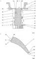
- FIG 3a section along the main axis through a component 1 is shown.
- Thisis a guide blade of a turbomachine, which has an airfoil 16, blade feet 18, an inner shroud 20, an outer shroud 22 and an inlet lining 24.
- the airfoil 16has a leading edge 26 which extends between the inner cover band 20 and the outer cover band 22 and a trailing edge 28 which extends between the inner cover band 20 and the outer cover band 22.
- the component or the guide vane 1consists of a base body 2 made of a first material and of two component sections 4a, 4b made of a different type of second material.
- the two component sections 4a, 4bare formed by the aerodynamically and thermally highly stressed leading edge 26 or the trailing edge 28 and by opposing hot gas surfaces 30, 32 of the cover strips 20, 22.
- the component sections 4a, 4bare positively toothed with the base body 2 (toothings 12a, 12b), each having a multiplicity of different toothing geometries 14a, 14b.
- the base body 2preferably consists of a metallic material and the component sections 26, 20, 30, 32 of a ceramic.
- the guide vane 1is thus a metal-ceramic composite in this embodiment.
- each component section 4a, 4bcan have a varying thickness.
- itcan have both relatively thin-walled areas 34 and thick-walled areas 36, which are many times thicker than the thin-walled areas 34.
- the thickness of the component sections 4a, 4bdepends on the respective loads acting on the component 1 in this area.
- the shape of the expansion joints 38, 38 'and their coursecan vary with each other. In general, their shape, their course and their positioning depend on the respective expansion and vibration behavior of the component 1.
- expansion joints 38, 38 'on the component section 4aare also conceivable.
- the production of the guide vane 1is preferably carried out by the second method Figure 2 (Simultaneous generative manufacture of the base body 2 and the component sections 4a, 4b).
- the guide vane 1can, however, also be produced by the first method according to FIG. 2 (generative production of the base body 2 and sintering with preferred rocking of the component section material filled in recesses 10a, 10b on the base body side).
- FIG 4a section transverse to the main axis through a further component 1 is shown.
- Thisis, for example, an airfoil of a guide or moving blade, wherein a leading edge 26 and a trailing edge 28 of the airfoil 1 are each made as a component section 4a, 4b from a material different from the basic body material.
- the airfoil 1is a metal-ceramic composite, wherein the base body 2 is metallic and the component sections 4a, 4b consist of a ceramic.
- the component sections 4a, 4bare globally toothed with the base body 2 by means of a multiplicity of different toothing geometries 14a, 14b.
- overlaps 40a, 40b of the base body 2 and the component sections 4a 4bare formed at outer joints between the base body 2 and the component sections 4a, 4b.
- thisresults in a smooth transition from the component sections 4a, 4b created on the base body 2, which has a favorable effect on the introduction of load from the component sections 4a, 4b into the base body 2.
- the overlaps 40a, 40bcreate large-area contact areas between the base body 2 and the component sections 4a, 4b, which has an attachment-promoting effect on the component sections 4a, 4b on the base body 2.
- the production of the guide vane 1is preferably carried out by the second method Figure 2 (Simultaneous generative manufacture of the base body 2 and the component sections 4a, 4b).
- the guide vane 1can, however, also be produced by the first method according to FIG. 2 (generative production of the base body 2 and sintering with preferred rocking of the component section material filled in recesses 10a, 10b on the base body side).
- Component 1here is an airfoil of a guide or moving blade, which is formed as a hollow profile with a cooling air duct 42.
- the cooling air duct 42is delimited on the circumference by a base body 2 made of a first material.
- a component section 4a, 4bmade of a different type of second material is provided.
- the airfoil 1is a metal-ceramic composite, wherein the base body 2 is metallic and the component sections 4a, 4b consist of a ceramic.
- the component sections 4a, 4bencompass the base body 2 in the area of the leading edge 26 and trailing edge 28 in a cap-like manner and are each interlocked with it globally by means of a large number of different toothing geometries 14a, 14b.
- a multiplicity of cooling air bores 44extend through the base body 2 and the front component section 4a.
- the production of the guide vane 1is preferably carried out by the second method Figure 2 (Simultaneous generative manufacture of the base body 2 and the component sections 4a, 4b).
- the guide vane 1can, however, also be produced by the first method according to FIG. 2 (generative production of the base body 2 and sintering with preferred rocking of the component section material filled in recesses 10a, 10b on the base body side).
- FIG 6a schematic representation of a component 1 according to the invention is shown.
- a component 1is a metal-ceramic composite, wherein the base body 2 is metallic and the component sections 4a, 4b consist of a ceramic.
- the component sections 4a, 4bare arranged in the region of a leading edge 26 and a trailing edge 28 of the airfoil 16.
- the component sections 4a, 4bare subdivided into a plurality of short segments 46, 46 'to avoid stretching and vibration problems due to the different materials, which are each spaced apart from one another by a web-like base body section 48.
- the segments 46, 46 'are positively toothed with the base body 2 (not shown) and can have a uniform length and a uniform thickness.
- the lengthcorresponds to a height or an extension from the bottom up and thus in the vertical.
- the thicknesscorresponds to an extension from right to left (component section 4a) or from left to right (component section 4b) and thus horizontally.
- their length and thicknesscan also vary.
- the production of the guide vane 1is preferably carried out by the second method Figure 2 (simultaneous generative production of the base body 2 and the component sections 4a, 4b).
- the guide vane 1can, however, also be produced by the first method according to FIG. 2 (generative production of the base body 2 and sintering with preferred rocking of the component section material filled in recesses 10a, 10b on the base body side).
- high-temperature-resistant reinforcing fiberscan be introduced into the component sections 4, 4a, 4b.
- the reinforcing fiberscan be introduced as woven, laid, knitted and the like. In addition, only several individual fibers are possible.
Landscapes
- Engineering & Computer Science (AREA)
- Manufacturing & Machinery (AREA)
- Mechanical Engineering (AREA)
- General Engineering & Computer Science (AREA)
- Chemical & Material Sciences (AREA)
- Materials Engineering (AREA)
- Composite Materials (AREA)
- Architecture (AREA)
- Turbine Rotor Nozzle Sealing (AREA)
Description
Translated fromGermanDie Erfindung betrifft ein Bauteil nach dem Oberbegriff des Patentanspruchs 1.The invention relates to a component according to the preamble of
In Strömungsmaschinen wie Fluggasturbinen oder stationären Gasturbinen sind die meisten Bauteile aufgrund der hohen mechanischen, chemischen und/oder thermischen Beanspruchung hochbelastet. Beispiele für insbesondere mechanisch hochbelaste Bauteile einer Strömungsmaschine sind Rollenlager, z.B. Kugellager oder Zylinderlager. Aufgrund von im Betrieb auftretenden Belastungen, beispielsweise durch Fliehkräfte der Rollenkörper bzw. Wälzkörper, Abrollbewegungen der Rollenkörper oder durch Schubkräfte, sind die äußeren Lagerschalen hohen Belastungen ausgesetzt. Als Folge dieser Belastungen kommt es regelmäßig zum Verschleiß wie "Fretting" und "Pitting". Um zum einen den hohen Belastungen standhalten zu können, und um zum anderen eine möglichst günstige Verteilung der sogenannten Hertzschen Pressung gewährleisten zu können, bestehen die Lagerschalen aus Werkstoffen bzw. Materialien mit entsprechenden Materialeigenschaften hinsichtlich ihrer Steifigkeit, Zähigkeit und Festigkeit. Bevorzugterweise bestehen die Lagerschalen aus einer Metalllegierung. Zudem werden ihre Lagerflächen mit Beschichtungen aus einem Material mit einer hohen Verschleißbeständigkeit wie Keramik versehen. Siehe hierzu beispielsweise die
Weitere hochbelastete Bauteile in Strömungsmaschinen sind beispielsweise Leit- und Laufschaufeln. Im Turbinenbereich werden die Leit- und Laufschaufeln regelmäßig mit Temperatur-, Oxidations- und Korrosionsschutzschichten versehen, die herkömmlicherweise durch ein thermisches Spitzverfahren aufgebracht werden. Im Verdichterbereich werden die Leit- und Laufschaufeln meistens mit Erosionsschutzschichten versehen, die ebenfalls durch ein thermisches Spritzverfahren aufgebracht werden. Zudem sind Vollkeramikschaufeln bekannt, die aufgrund des keramischen Werkstoffes eine höhere Temperaturbeständigkeit und damit einen geringeren Kühlbedarf als die auf einem metallischen Werkstoff basierenden Leit- und Laufschaufeln haben.Other highly stressed components in turbomachinery are, for example, guide and rotor blades. In the turbine area, the guide and rotor blades are regularly provided with layers of temperature, oxidation and corrosion protection, which are conventionally applied using a thermal pointed process. In the compressor area, the guide and rotor blades are usually provided with erosion protection layers, which are also applied by a thermal spray process. In addition, all-ceramic blades are known which, owing to the ceramic material, have a higher temperature resistance and thus a lower cooling requirement than the guide and rotor blades based on a metallic material.
Nachteilig an den vorgenannten Verschleiß und Schutzschichten ist jedoch, dass sie nur in dünnen Schichten aufgebracht werden, da sie sonst abplatzen. Vollkeramikschaufeln sind insofern problematisch, als das die Keramik eine hohe Sprödbruchneigung, eine geringe Temperaturschockbeständigkeit und eine geringe Duktilität aufweist, wodurch bereits eine kleine Beschädigung zu einer vollständigen Zerstörung der Vollkeramikschaufeln führen kann.A disadvantage of the abovementioned wear and protective layers, however, is that they are only applied in thin layers, since they would otherwise flake off. All-ceramic blades are problematic in that the ceramic has a high tendency to brittle fracture, a low temperature shock resistance and a low ductility, which means that even small damage can lead to complete destruction of the all-ceramic blades.
Weiterer Stand der Technik ist in der
Aufgabe der Erfindung ist es ein hochbelastbares Bauteil zu schaffen, das eine hohe Beständigkeit gegen mechanische, thermische und/oder chemische Belastungen aufweist und zudem ein optimiertes Versagensverhalten zeigt.The object of the invention is to create a highly resilient component which has a high resistance to mechanical, thermal and / or chemical loads and also shows an optimized failure behavior.
Diese Aufgabe wird gelöst durch ein Bauteil mit den Merkmalen des Patenanspruchs 1.This object is achieved by a component with the features of
Ein erfindungsgemäßes Bauteil für eine Strömungsmaschine, mit einem generativ hergestellten Grundkörper aus einem ersten Material und mit zumindest einem an dem Grundkörper aufgebauten Bauteilabschnitt aus einem andersartigen zweiten Material, ist hergestellt, indem der zumindest eine Bauteilabschnitt am Grundkörper entweder generativ aufgebaut ist oder durch Aufbringen des zweiten Materials in trockener Pulverform oder als Dispersion auf den Grundkörper und anschließendem Sintern unterhalb der Schmelztemperatur des Grundkörpermaterials aufgebaut ist.A component according to the invention for a fluid-flow machine, with a generatively produced base body made of a first material and with at least one component section built up on the base body made of a different type of second material, is produced in that the at least one component section is either built generatively on the base body or by applying the second one Material is built up in dry powder form or as a dispersion on the base body and subsequent sintering below the melting temperature of the base body material.
Ein derartiges Bauteil ist ein Hybridbauteil mit zumindest zwei Bereichen aus unterschiedlichen Materialien. Es zeichnet sich durch eine hohe mechanische, chemische und thermische Belastbarkeit sowie durch ein optimiertes Versagensverhalten aus.Such a component is a hybrid component with at least two areas made of different materials. It is characterized by a high mechanical, chemical and thermal resilience as well as an optimized failure behavior.
Bevorzugterweise ist der zumindest eine Bauteilabschnitt in den Bauteilbereichen vorgesehen, in denen das Bauteil einer chemischen Belastung wie Oxidation, Korrosion, Erosion, einer hohen thermischen Belastung und und/oder einer hohen mechanischen Belastung wie einem Verschleiß ausgesetzt ist. Alternativ kann der zumindest eine Bauteilabschnitt jedoch auch dämpfende Eigenschaften aufweisen und beispielsweise neben einem andersartigen Material als der Grundkörper eine andere Struktur als dieser aufweisen.The at least one component section is preferably provided in the component regions in which the component is exposed to a chemical load such as oxidation, corrosion, erosion, a high thermal load and / or a high mechanical load such as wear. Alternatively, however, the at least one component section can also have damping properties and, for example, in addition to a different type of material than the base body, can have a different structure than this.
Beispielhafte Bauteile, insbesondere von Strömungsmaschinen, sind Lageschalen, aerodynamische Profile oder Vorderkanten und Hinterkanten einer Laufschaufel oder Leitschaufel, Haken von Leitschaufeln, Flansche, Laufschaufelfüße, Dichtstreifen bei Segmentdichtungen zum Beispiel an Leitschaufeln, Strukturrippen in Maschinengehäusen, Innendeckbänder und/oder Außendeckbänder.Exemplary components, in particular of flow machines, are position shells, aerodynamic profiles or leading edges and trailing edges of a moving blade or guide blade, hooks of guide blades, flanges, moving blade feet, sealing strips for segment seals, for example on guide blades, structural ribs in machine housings, inner cover strips and / or outer cover strips.
Der zumindest eine Bauteilabschnitt ist mit dem Grundkörper formschlüssig verzahnt. Hierdurch wird eine globale Verzahnung von mehreren Millimetern geschaffen, die eine besonders belastbare Verbindung des zumindest einen Bauteilabschnittes an den Grundkörper schafft.The at least one component section is interlocked with the base body. This creates a global toothing of several millimeters, which creates a particularly resilient connection of the at least one component section to the base body.
Zur Stabilisierung der Verzahnung weist diese verschiedene Verzahnungsgeometrieen auf. Zudem kann die Verzahnung verschiedene Verzahnungsrichtungen aufweisen. Sowohl durch die verschiedenen Verzahnungsgeometrieen als auch durch die verschiedenen Verzahnungsrichtungen kann die Verzahnung gezielt auf mechanische Belastungsrichtungen eingestellt werden.To stabilize the toothing, it has different toothing geometries. In addition, the toothing can have different toothing directions. The toothing can be specifically adjusted to mechanical load directions by the different toothing geometries as well as by the different toothing directions.
Zur Vermeidung von Dehnungs- und Schwingungsproblemen in Folge der unterschiedlichen Materialien ist der zumindest eine Bauteilabschnitt segmentiert. Der zumindest eine Bauteilabschnitt ist somit in einzelne Segmente unterteilt, die über schmale Grundkörperbereiche voneinander beabstandet sind, so dass beispielsweise Spannungsrisse in dem zumindest einen Bauteilabschnitt verhindert werden.To avoid stretching and vibration problems due to the different materials, the at least one component section is segmented. The at least one component section is thus subdivided into individual segments, which are separated from one another by narrow basic body regions are spaced so that, for example, stress cracks in the at least one component section are prevented.
Der zumindest eine Bauteilabschnitt kann zumindest eine Dehnungsfuge aufweisen. Im Unterschied zur Segmentierung ist in den Dehnungsfugen kein Grundkörpermaterial angeordnet, so dass sich Bauteilabschnittskanten, die jeweils eine Dehnungsfugen bilden, frei gegenüber liegen.The at least one component section can have at least one expansion joint. In contrast to the segmentation, no base body material is arranged in the expansion joints, so that component section edges, which each form an expansion joint, lie freely opposite one another.
Des Weiteren können zusätzlich zur Vermeidung von Dehnungs- und Schwingungsproblemen in dem zumindest einen Bauteilabschnitt Verstärkungsfasern eingebracht sein. Die Verstärkungsfasern sind beispielsweise hochtemperaturfeste Fasern wie Kohlenstofffasern, Glasfasern oder Aramidfasern. Um die Dehnungen und Schwingungen gezielt aufnehmen zu können, sind sie bevorzugterweise in Belastungsrichtung in den zumindest einen Bauteilabschnitt integriert. So sind sie bevorzugterweise in Richtungen von zu erwartenden Zugspannungen orientiert. Die Verstärkungsfasern können als Gewebe, Gelege, Gewirk und dergleichen eingebracht sein. Zudem sind lediglich mehrere Einzelfasern möglich.In addition, reinforcement fibers can be introduced in the at least one component section in addition to avoiding stretching and vibration problems. The reinforcing fibers are, for example, high-temperature-resistant fibers such as carbon fibers, glass fibers or aramid fibers. In order to be able to absorb the strains and vibrations in a targeted manner, they are preferably integrated in the at least one component section in the direction of loading. They are preferably oriented in the directions of expected tensile stresses. The reinforcing fibers can be introduced as woven, laid, knitted and the like. In addition, only several individual fibers are possible.
Bevorzugterweise bilden der zumindest eine Baueilabschnitt und der Grundkörper an äußeren Stoßstellen Überlappungen. Hierdurch wird zum einen ein sanfter Übergang von den Bauteilabschnitten auf den Grundkörper geschaffen, was sich günstig auf die Belastungseinleitung von den Bauteilabschnitten in den Grundkörper auswirkt. Zum anderen werden durch die Überlappungen großflächige Kontaktbereiche zwischen dem Grundkörper und den Bauteilabschnitten geschaffen, was befestigungsfördernd für den zumindest einen Bauteilabschnitt an dem Grundkörper ist.The at least one component section and the base body preferably form overlaps at outer joints. On the one hand, this creates a smooth transition from the component sections to the base body, which has a favorable effect on the introduction of load from the component sections into the base body. On the other hand, the overlaps create large-area contact areas between the base body and the component sections, which promotes attachment for the at least one component section on the base body.
Bei einem Ausführungsbeispiel ist zumindest der zumindest eine Bauteilabschnitt mit einer gesinterten Deckschicht versehen. Durch das Sintern ist die Deckschicht zumindest mittels einer Mikroverzahnung mit dem zumindest einen Bauteilabschnitt verbunden, so dass diese durch die Mikroverzahnung eine hohe Adhäsion und somit beispielsweise ein sehr geringes Abplatzrisiko zeigt.In one exemplary embodiment, at least the at least one component section is provided with a sintered cover layer. As a result of the sintering, the cover layer is connected to the at least one component section at least by means of a micro-toothing, so that the micro-toothing shows a high adhesion and thus, for example, a very low risk of chipping.
Sonstige vorteilhafte Ausführungsbeispiele der Erfindung sind Gegenstand weiterer Unteransprüche.Other advantageous embodiments of the invention are the subject of further dependent claims.
Bei einem bevorzugten Verfahren zur Herstellung eines erfindungsgemäßen Bauteils, das einen Grundkörper aus einem ersten Material und zumindest einen Bauteilabschnitt aus einem andersartigen zweiten Material hat, wird zuerst eine Bauteilform definiert. Dann wird der Grundkörper generativ hergestellt. Gleichzeitig beim generativen Herstellen des Grundkörpers wird der zumindest eine Bauteilabschnitt generativ an dem Grundkörper aufgebaut, wobei zwischen dem Grundkörper und dem zumindest einen Bauteilabschnitt eine formflüssige Verzahnung gebildet wird.In a preferred method for producing a component according to the invention, which has a base body made of a first material and at least one component section made of a different type of second material, a component shape is first defined. Then the base body is produced generatively. At the same time as the additive manufacturing of the base body, the at least one component section is built up generatively on the base body, a positive toothing being formed between the base body and the at least one component section.
Die formschlüssige Verzahnung ist eine sogenannte globale Verzahnung, die sich mehrere Millimeter in den Grundkörper hinein erstrecken kann. Sie bildet quasi einen Anker des Bauteilabschnitts in dem Grundkörper, wodurch dieser besonders belastbar mit dem Grundkörper verbunden ist. Zudem bewirkt die formschlüssige Verzahnung, dass bei einer Beschädigung eines Bauteilabschnittsbereiches ein unbeschädigter Bauteilabschnittsbereich unversehrt bleibt, so dass ein Totalversagen des Bauteils wirkungsvoll verhindert wird.The positive toothing is a so-called global toothing that can extend several millimeters into the base body. It virtually forms an anchor of the component section in the base body, as a result of which it is connected to the base body in a particularly load-bearing manner. In addition, the positive toothing has the effect that if a component section area is damaged, an undamaged component section area remains intact, so that total failure of the component is effectively prevented.
Mittels des Verfahrens werden Hybridbauteile gebildet, die zumindest zwei fest miteinander verbundende Bauteilbereiche aus unterschiedlichen Material aufweisen. In Abhängigkeit vom gewählten Material kann der zumindest eine Bauteilabschnitt gezielt eingestellt werden. Beispielsweise kann der Grundkörper metallisch sein und der zumindest eine Bauteilabschnitt auf einer Keramik basieren. Durch eine solche Hybridbauweise wird beispielsweise der katastrophale Schadensverlauf einer Vollkeramikschaufel verhindert. Selbstverständlich kann das Bauteilabschnittsmaterial bei einem metallischen Grundkörper auch metallisch sein, jedoch dann aus einem andersartigen Metall bzw. einer andersartigen Metalllegierung. Die generative Herstellung des Bauteils kann in einem Pulverbett oder pulverbettfrei ähnlich dem Fused Deposition Modeling erfolgen. Bevorzugterweise werden die Materialien als Nanopulver bereitgestellt, was neben einer hohen Verdichtung die Ausbildung des Bauteilabschnitts als Dünnschicht erlaubt.By means of the method, hybrid components are formed which have at least two component regions made of different materials which are firmly connected to one another. Depending on the material selected, the at least one component section can be specifically set. For example, the base body can be metallic and the at least one component section is based on a ceramic. Such a hybrid construction prevents, for example, the catastrophic damage process of an all-ceramic blade. Of course, the component section material can also be metallic in the case of a metallic base body, but then made of a different type of metal or a different type of metal alloy. The additive manufacturing of the component can be done in a powder bed or powder bed-free similar to fused deposition modeling. The materials are preferably provided as nanopowders, which, in addition to high compaction, allows the component section to be formed as a thin layer.
Bei einem alternativen Verfahren zur Herstellung eines erfindungsgemäßen Bauteils, das einen Grundkörper aus einem ersten Material und zumindest einem Bauteilabschnitt aus einem andersartigen zweiten Material hat, wird zuerst eine Bauteilform definiert. Dann wird der Grundkörper generativ hergestellt. Anschließend wird der zumindest eine Bauteilabschnitt an dem Grundkörper aufgebaut, wobei das zweite Material bzw. das Bauteilabschnittmaterial in trockener Pulverform oder als Dispersion auf den Grundkörper aufgebracht wird. Danach wird das Bauteilabschnittmaterial unterhalb einer Schmelztemperatur des ersten Materials bzw. des Grundkörpermaterials gesintert.In an alternative method for producing a component according to the invention, the one Basic body made of a first material and at least one component section made of a different type of second material, a component shape is first defined. Then the base body is produced generatively. The at least one component section is then built up on the base body, the second material or the component section material being applied to the base body in dry powder form or as a dispersion. The component section material is then sintered below a melting temperature of the first material or the base body material.
Durch das Sintern lässt sich zumindest eine Mikroverzahnung zwischen dem Grundkörper und dem zumindest einen Bauteilabschnitt erzielen. Die Mikroverzahnung bewirkt eine hohe Adhäsion zwischen dem Grundkörper und dem zumindest einen Bauteilabschnitt, so dass, wenn beispielsweise der Bauteilabschnitt eine Dünnschicht in Form einer Verschleißschicht oder einer Schutzschicht ist, diese besonders fest mit dem Grundkörper verbunden ist und ein Abplatzrisiko aufgrund von mechanischen, chemischen und/oder thermischen Belastungen signifikant gesenkt wird. Beispielsweise ist das Grundkörpermaterial metallisch und das Bauteilabschnittsmaterial eine Keramik. Selbstverständlich kann das Bauteilabschnittsmaterial bei einem metallischen Grundkörper auch metallisch sein, jedoch dann aus einem andersartigen Metall bzw. einer andersartigen Metalllegierung. Die Durchführung des Verfahrens kann in einem Pulverbett oder pulverbettfrei erfolgen. Bevorzugterweise wird das Bauteilabschnittsmaterial als Nanopulver in trockener oder flüssiger Form (Dispersion) bereitgestellt.Sintering enables at least one micro toothing to be achieved between the base body and the at least one component section. The micro-toothing brings about a high level of adhesion between the base body and the at least one component section, so that if, for example, the component section is a thin layer in the form of a wear layer or a protective layer, it is particularly firmly connected to the base body and there is a risk of chipping due to mechanical, chemical and / or thermal loads is significantly reduced. For example, the base body material is metallic and the component section material is ceramic. Of course, the component section material in a metallic base body can also be metallic, but then made of a different type of metal or a different type of metal alloy. The process can be carried out in a powder bed or without a powder bed. The component section material is preferably provided as nanopowder in dry or liquid form (dispersion).
Das Verfahren ermöglicht es auch, den Bauteilabschnitt in mehreren Lagen aufzubringen. Hierdurch kann eine Dicke des Bauteilabschnittes lagenweise gesteigert werden, wobei die Lagen einzeln mittels Mikroverzahnung miteinander verbunden werden, so dass ein derartiger dickwandiger Bauteilabschnitt hochbelastbar ist.The method also makes it possible to apply the component section in several layers. In this way, a thickness of the component section can be increased in layers, the layers being individually connected to one another by means of micro-toothing, so that such a thick-walled component section can be subjected to high loads.
Bei einem Ausführungsbeispiel, bei dem der zumindest eine aufzubauende Bauteilabschnitt eine Schichtdicke im Bereich von Dickschichten mit einigen Millimetern liegen soll, wird beim Schritt "generatives Herstellen des Grundkörpers in dem Grundkörper" zumindest eine Aussparung zur Bildung einer formschlüssigen Verzahnung zwischen den Grundkörper und den zumindest einem Bauteilabschnitt eingebracht und beim Schritt "Aufbauen des zumindest einen Bauteilabschnitts am Grundkörper" die zumindest eine Aussparung mit dem zweiten Material bzw. dem Bauteilabschnittsmaterial aufgefüllt. Durch die formflüssige Verzahnung wird eine globale Verzahnung gebildet, die eine hochbelastbare Verankerung des zumindest einen Bauteilabschnitts an dem Grundkörper schafft.In one exemplary embodiment, in which the at least one component section to be built up is to have a layer thickness in the region of thick layers with a few millimeters, in the step "generative manufacture of the base body in the base body" there is at least one recess for forming a positive toothing between the base body and the at least one introduced a component section and in the step "building up the at least one component section on the base body" the at least one recess is filled with the second material or the component section material. A global toothing is formed by the fluid toothing, which creates a heavy-duty anchoring of the at least one component section on the base body.
Zudem kann zumindest auf den zumindest einen Bauteilabschnitt durch Sintern eine Deckschicht aufgebracht werden. Die Deckschicht ist bevorzugterweise eine Dünnschicht, die zur Vergrößerung ihrer Dicke in mehreren Lagen aufgetragen werden kann.In addition, a cover layer can be applied to the at least one component section by sintering. The cover layer is preferably a thin layer which can be applied in several layers to increase its thickness.
Die Erfindung wird anhand schematischer Darstellungen näher erläutert, wobei
Figur 1- einen Schnitt durch eine erste äußere Lagerschale,
Figur 2- einen Schnitt durch eine zweite äußere Lagerschale,
- Figur 3
- einen Schnitt durch eine Leitschaufel,
- Figur 4
- einen Schnitt durch ein erstes Schaufelblatt,
- Figur 5
- einen Schnitt durch ein zweites Schaufelblatt, und
Figur 6- einen Schnitt durch ein erfindungsgemäßes Bauteil.
- Figure 1
- a section through a first outer bearing shell,
- Figure 2
- a section through a second outer bearing shell,
- Figure 3
- a section through a guide vane,
- Figure 4
- a section through a first airfoil,
- Figure 5
- a section through a second airfoil, and
- Figure 6
- a section through an inventive component.
Im Folgenden haben gleiche konstruktive Elemente gleich Bezugszeichen, wobei bei mehreren gleichen konstruktiven Elementen in einer Figur lediglich einige der gleichen konstruktiven Elemente mit einem Bezugszeichen versehen sind.In the following, identical design elements have the same reference numerals, with only a few of the same design elements being provided with a reference number in the case of several identical design elements in a figure.
Der Bauteilabschnitt 4 ist in einer Senke 6 des Grundkörpers 2 angeordnet und bildet mit diesem eine ebene Oberfläche 8. Beispielsweise ist der Bauteilabschnitt 4 eine mechanisch hochbelastete dünnschichtartige keramische Lauf- bzw. Verschleißfläche für Wälzkörper, die durch die äußere Lagerschale 1 geführt werden.The component section 4 is arranged in a
Bei einem Verfahren zur Herstellung des Bauteils 1 wird zuerst dessen Bauteilform definiert. Dann wird der Grundkörper 2 generativ hergestellt. Danach wird der Bauteilabschnitt 4 als Nanopulver in trockener Form oder als Dispersion auf den Grundkörper 2 aufgebracht bzw. in der Senke 6 angeordnet. Bevorzugterweise ist in der Dispersion ein metallisches Bindemittel enthalten. Anschließend wird das Bauteilabschnittmaterial unterhalb einer Schmelztemperatur des Grundkörpermaterials 2 im Vakuum unter Druck gesintert und bevorzugterweise nachverdichtet. Das Nachverdichten erfolgt beispielsweise mittels einer heißisostatischen Nachverpressung (Hippen). Als Ergebnis des Herstellungsverfahrens hat die äußere Lagerschale 1 eine mit dem Grundkörper 2 mikroverzahnte keramische dünnschichtartige Lauffläche 4. Dabei ist auch ein graduierter Aufbau des Bauteilabschnittes 4 bzw. der keramischen Lauffläche in mehreren sehr dünnen Lagen möglich.In a method for producing the
In
Im Wesentlichen Unterschied zum ersten Beispiel ist der Bauteilabschnitt 4 mit dem Grundkörper 2 formschlüssig verzahnt. Hierzu weist der Grundkörper 2 eine Vielzahl von Aussparungen 10a, 10b auf, die mit dem Bauteilabschnittsmaterial 4 aufgefüllt sind, sodass zwischen den Bauteilabschnitt 4 und dem Grundkörper 2 eine formschlüssige beziehungsweise globale Verzahnung 12 gebildet ist. Die Verzahnung 12 erstreckt sich mehrere Millimeter in den Grundkörper 2 hinein und weist eine Vielzahl von unterschiedlichen Verzahnungsgeometrieen 14a, 14b auf. Während beispielsweise die Verzahnungsgeometrie 14a L-förmig ist und einen abgewinkelten Grundabschnitt hat, ist die andere Verzahnungsgeometrie 14b stiftartig. Vorzugsweise erstrecken sich die Verzahnungsgeometrieen 14a, 14b in Stützrichtung und somit radial von der Lauffläche 4 weg. Die Schichtdicke der Lauffläche 4 an sich hat sich im Vergleich zum ersten Ausführungsbeispiel nicht verändert, so dass auch dieser Bauteilabschnitt 4 trotz seiner Verzahnung 12 eine Dünnschicht ist.Essentially different from the first example, the component section 4 is interlocked with the
Bei einem ersten Verfahren zur Herstellung des Bauteils 1 nach
Bei einem zweiten Verfahren zur Herstellung des Bauteils 1 nach
In
Das Bauteil bzw. die Leitschaufel 1 besteht aus einem Grundkörper 2 aus einem ersten Material und aus zwei Bauteilabschnitten 4a, 4b aus einem andersartigen zweiten Material. In dem hier gezeigten Beispiel werden die beiden Bauteilabschnitte 4a, 4b von der aerodynamisch und thermisch hochbelasteten Anströmkante 26 bzw. der Abströmkante 28 sowie von gegenüberliegenden Heißgasflächen 30, 32 der Deckbänder 20, 22 gebildet. Die Bauteilabschnitte 4a, 4b sind mit dem Grundkörper 2 formschlüssige verzahnt (Verzahnungen 12a, 12b), wobei jeweils eine Vielzahl von unterschiedlichen Verzahnungsgeometrieen 14a, 14b aufweist. Vorzugsweise besteht der Grundkörper 2 aus einem metallischen Werkstoff und die Bauteilabschnitte 26, 20, 30, 32 aus einer Keramik. Die Leitschaufel 1 ist somit in diesem Ausführungsbeispiel ein Metall-Keramik-Verbund.The component or the
Zudem kann jeder Bauteilabschnitte 4a, 4b eine variierende Dicke haben. So kann er sowohl verhältnismäßig dünnwandige Bereiche 34, als auch dickwandige Bereiche 36 aufweisen, die um ein Vielfaches dicker als die dünnwandigen Bereiche 34 ausgeführt sind. Im Allgemeinen richtet sich die Dicke der Bauteilabschnitte 4a, 4b nach den jeweiligen auf das Bauteil 1 in diesem Bereich wirkenden Belastungen.In addition, each
Zum Ausgleich von unterschiedlichen Dehnungs- und Schwingungsverhalten des Grundkörpermaterials zum Bauteilabschnittsmaterial sind in dem hier gezeigten Ausführungsbeispiel im in Strömungsrichtung einer Heißgasströmung betrachtet hinteren Bauteilabschnitten 4a, 4b zwei Dehnungsfugen 38, 38' eingebracht. Die Dehnungsfugen 38, 38' befinden sich im jeweiligen Übergangsbereich der Abströmkante 28 zu den Heißgasflächen 30, 32. Sie erstrecken sich vollständig durch den hinteren Bauteilabschnitt 4b und unterteilen diesen in drei einzelne Bereiche (Abströmkante 28, Heißgasflächen 30, Heißgasfläche 32) auf, die somit körperlich voneinander getrennt sind. Wie in
Die Herstellung der Leitschaufel 1 erfolgt bevorzugterweise nach dem zweiten Verfahren nach
In
Wie in
Die Herstellung der Leitschaufel 1 erfolgt bevorzugterweise nach dem zweiten Verfahren nach
In
Die Bauteilabschnitte 4a, 4b umgreifen den Grundkörper 2 im Bereich der Anströmkante 26 und Abströmkante 28 kappenartig und sind mit diesem jeweils global mittels einer Vielzahl von unterschiedlichen Verzahnungsgeometrieen 14a, 14b verzahnt. Zum Ausblasen von Kühlluft aus dem Kühlluftkanal 42 auf die aerodynamisch und thermisch hochbelastete Anströmkante 26 erstreckt sich durch den Grundkörper 2 und den vorderen Bauteilabschnitt 4a eine Vielzahl von Kühlluftbohrungen 44.The
Wie zudem in
Die Herstellung der Leitschaufel 1 erfolgt bevorzugterweise nach dem zweiten Verfahren nach
In
Die Bauteilabschnitte 4a, 4b sind im Bereich einer Anströmkante 26 und einer Abströmkante 28 des Schaufelblattes 16 angeordnet. Die Bauteilabschnitte 4a, 4b sind zur Vermeidung von Dehnungs- und Schwingungsproblemen aufgrund der unterschiedlichen Materialien in eine Vielzahl von kurzen Segmenten 46, 46' unterteilt, die jeweils über einen stegartigen Grundkörperabschnitt 48 voneinander beabstandet sind. Die Segmente 46, 46' sind mit dem Grundkörper 2 formschlüssig verzahnt (nicht gezeigt) und können eine einheitliche Länge und eine einheitliche Dicke aufweisen. In der gezeigten Perspektive entspricht die Länge einer Höhe bzw. einer Erstreckung von unten nach oben und somit in der Vertikalen. Die Dicke entspricht in der gezeigten Perspektive einer Erstreckung von rechts nach links (Bauteilabschnitt 4a) bzw. von links nach rechts (Bauteilabschnitt 4b) und somit in der Horizontalen. Selbstverständlich kann ihre Länge und Dicke jedoch auch variieren.The
Die Herstellung der Leitschaufel 1 erfolgt bevorzugterweise nach dem zweiten Verfahren nach
Bei sämtlichen Beispielen und insbesondere bei den Bauteilen 1 mit den dickwandigen Bauteilabschnittsbereichen 36 (s.
Ferner können sämtliche Beispiele nach ihrer Herstellung zum Einstellen einer Sollform mechanisch nachbearbeitet werden.Furthermore, all examples can be mechanically reworked after their production to set a desired shape.
Zudem können sämtliche Beispiele nach ihrer Herstellung abschnittsweise oder vollumfänglich mit einer dünnwandigen Deckschicht versehen werden, die gemäß dem ersten Verfahren nach
- 11
- Bauteilcomponent
- 22
- Grundkörperbody
- 4, 4a, 4b4, 4a, 4b
- Bauteilabschnittcomponent section
- 66
- Senkedepression
- 88th
- Oberflächesurface
- 66
- Senkedepression
- 1010
- Aussparungrecess
- 12, 12a, 12b12, 12a, 12b
- Verzahnunggearing
- 14, 14a, 14b14, 14a, 14b
- Verzahnungsgeometrietooth geometry
- 1616
- Schaufelblattairfoil
- 1818
- Schaufelfußblade
- 2020
- InnendeckbandInner shroud
- 2222
- AußendeckbandOuter shroud
- 2424
- Einlaufbelaginlet lining
- 2626
- Anströmkanteleading edge
- 2828
- Abströmkantetrailing edge
- 3030
- HeißgasflächeHot gas area
- 3232
- HeißgasflächeHot gas area
- 3434
- dünnwandiger Bereichthin-walled area
- 3636
- dickwandiger Bereichthick-walled area
- 38, 38'38, 38 '
- Dehnungsfugeexpansion
- 40a, b40a, b
- Überlappungoverlap
- 4242
- KühlluftkanalCooling air duct
- 4444
- KühlluftbohrungCooling air hole
- 46, 46'46, 46 '
- Segmentsegment
- 4848
- GrundkörperabschnittBody part
Claims (5)
- Component for a turbomachine, comprising an additively manufactured main part (2) made of a first material, and at least one component portion (4, 4a, 4b) constructed on the main part (2), which portion is made of a different second material, the main part (2) and the at least one component portion (4, 4a, 4b) being interlocked in a toothed manner such that the interlocking toothing more or less forms an anchor of the component portion in the main part, the interlocking toothing (12) between the main part (2) and the at least one component portion (4, 4a, 4b) having different toothing geometries (14a, 14b), and the at least one component portion (4, 4a, 4b) on the main part (2) either being constructed additively or by means of applying the second material in dry powder form or as a dispersion to the main part, and then sintering below the melting temperature of the material of the main part,characterized in that the at least one component portion (4, 4a, 4b) is segmented in such a way that it is divided into individual segments which are spaced apart from one another by narrow regions of the main part.
- Component according to claim 1, wherein the at least one component portion (4, 4a, 4b) has at least one expansion joint (38, 38').
- Component according to either claim 1 or claim 2, wherein reinforcing fibers are introduced into the at least one component portion (4, 4a, 4b).
- Component according to any of the preceding claims, wherein the at least one component portion (4, 4a, 4b) and the main part (2) form overlapping regions (40a, 40b) at outer joints.
- Component according to any of the preceding claims, wherein at least the at least one component portion (4, 4a, 4b) is provided with a sintered cover layer.
Priority Applications (2)
| Application Number | Priority Date | Filing Date | Title |
|---|---|---|---|
| EP12188332.6AEP2719484B1 (en) | 2012-10-12 | 2012-10-12 | Component for turbomachine |
| ES12188332TES2777927T3 (en) | 2012-10-12 | 2012-10-12 | Component for a turbine |
Applications Claiming Priority (1)
| Application Number | Priority Date | Filing Date | Title |
|---|---|---|---|
| EP12188332.6AEP2719484B1 (en) | 2012-10-12 | 2012-10-12 | Component for turbomachine |
Publications (2)
| Publication Number | Publication Date |
|---|---|
| EP2719484A1 EP2719484A1 (en) | 2014-04-16 |
| EP2719484B1true EP2719484B1 (en) | 2020-02-26 |
Family
ID=47191512
Family Applications (1)
| Application Number | Title | Priority Date | Filing Date |
|---|---|---|---|
| EP12188332.6AActiveEP2719484B1 (en) | 2012-10-12 | 2012-10-12 | Component for turbomachine |
Country Status (2)
| Country | Link |
|---|---|
| EP (1) | EP2719484B1 (en) |
| ES (1) | ES2777927T3 (en) |
Families Citing this family (21)
| Publication number | Priority date | Publication date | Assignee | Title |
|---|---|---|---|---|
| GB2521600A (en)* | 2013-12-18 | 2015-07-01 | Skf Ab | A building block for a mechanical construction |
| DE102014010930A1 (en)* | 2014-07-28 | 2016-01-28 | Cl Schutzrechtsverwaltungs Gmbh | Device and method for producing three-dimensional objects |
| KR102240108B1 (en) | 2014-11-24 | 2021-04-14 | 피피지 인더스트리즈 오하이오 인코포레이티드 | Methods for reactive three-dimensional printing by extrusion |
| DE102015101686A1 (en)* | 2015-02-05 | 2016-08-11 | Berkenhoff Gmbh | Metal parts with a profiled surface, in particular wear plate for scrap presses |
| DE102015115406A1 (en)* | 2015-09-11 | 2017-03-16 | Jakob Lach Gmbh & Co. Kg | Method for producing a component |
| US9914172B2 (en)* | 2015-10-20 | 2018-03-13 | General Electric Company | Interlocking material transition zone with integrated film cooling |
| US10370975B2 (en) | 2015-10-20 | 2019-08-06 | General Electric Company | Additively manufactured rotor blades and components |
| US10180072B2 (en) | 2015-10-20 | 2019-01-15 | General Electric Company | Additively manufactured bladed disk |
| US9884393B2 (en) | 2015-10-20 | 2018-02-06 | General Electric Company | Repair methods utilizing additively manufacturing for rotor blades and components |
| US10184344B2 (en) | 2015-10-20 | 2019-01-22 | General Electric Company | Additively manufactured connection for a turbine nozzle |
| DE102016208196B4 (en)* | 2016-05-12 | 2019-08-29 | Fraunhofer-Gesellschaft zur Förderung der angewandten Forschung e.V. | Method for the generative production of three-dimensional composite components |
| CA3039851A1 (en)* | 2016-10-21 | 2018-04-26 | Mosaic Manufacturing Ltd. | Joiners, methods of joining, and related systems for additive manufacturing |
| DE102017201035A1 (en) | 2017-01-23 | 2018-07-26 | Bruker Eas Gmbh | Method for producing an at least two-part structure, in particular a semifinished product for a superconducting wire |
| DE102017106722A1 (en)* | 2017-03-29 | 2018-10-04 | Universität Stuttgart | Process for jet-based melting or sintering |
| US10434704B2 (en) | 2017-08-18 | 2019-10-08 | Ppg Industries Ohio, Inc. | Additive manufacturing using polyurea materials |
| US12384097B2 (en) | 2017-08-18 | 2025-08-12 | Ppg Industries Ohio, Inc. | Additive manufacturing using reactive compositions |
| US20200001368A1 (en)* | 2018-06-29 | 2020-01-02 | United Technologies Corporation | Fabricating composite metallic components |
| DE102018212343A1 (en)* | 2018-07-25 | 2020-01-30 | MTU Aero Engines AG | Process for building up a component in layers |
| CN109079141B (en)* | 2018-08-31 | 2020-11-20 | 航天材料及工艺研究所 | An outer casing and method for eliminating dimensional deviation of rib structure in powder metallurgy components |
| AU2020221466B2 (en) | 2019-02-11 | 2022-12-15 | Ppg Industries Ohio, Inc. | Methods of making chemically resistant sealing components |
| CA3129262C (en) | 2019-02-11 | 2024-01-09 | Ppg Industries Ohio, Inc. | Multilayer systems and methods of making multilayer systems |
Citations (3)
| Publication number | Priority date | Publication date | Assignee | Title |
|---|---|---|---|---|
| US20090183850A1 (en)* | 2008-01-23 | 2009-07-23 | Siemens Power Generation, Inc. | Method of Making a Combustion Turbine Component from Metallic Combustion Turbine Subcomponent Greenbodies |
| EP2428309A2 (en)* | 2010-09-14 | 2012-03-14 | MTU Aero Engines AG | Joining element and method for producing such a joining element and integrated bladed rotor (Blisk) |
| EP2903762A2 (en)* | 2012-10-08 | 2015-08-12 | Siemens Aktiengesellschaft | Additive manufacture of turbine component with multiple materials |
Family Cites Families (5)
| Publication number | Priority date | Publication date | Assignee | Title |
|---|---|---|---|---|
| US5837960A (en)* | 1995-08-14 | 1998-11-17 | The Regents Of The University Of California | Laser production of articles from powders |
| DE19935274C1 (en)* | 1999-07-27 | 2001-01-25 | Fraunhofer Ges Forschung | Apparatus for producing components made of a material combination has a suction and blowing device for removing material from the processing surface, and a feed device for a further material |
| US7429165B2 (en)* | 2006-06-14 | 2008-09-30 | General Electric Company | Hybrid blade for a steam turbine |
| EP2319641B1 (en)* | 2009-10-30 | 2017-07-19 | Ansaldo Energia IP UK Limited | Method to apply multiple materials with selective laser melting on a 3D article |
| US20120034101A1 (en)* | 2010-08-09 | 2012-02-09 | James Allister W | Turbine blade squealer tip |
- 2012
- 2012-10-12ESES12188332Tpatent/ES2777927T3/enactiveActive
- 2012-10-12EPEP12188332.6Apatent/EP2719484B1/enactiveActive
Patent Citations (3)
| Publication number | Priority date | Publication date | Assignee | Title |
|---|---|---|---|---|
| US20090183850A1 (en)* | 2008-01-23 | 2009-07-23 | Siemens Power Generation, Inc. | Method of Making a Combustion Turbine Component from Metallic Combustion Turbine Subcomponent Greenbodies |
| EP2428309A2 (en)* | 2010-09-14 | 2012-03-14 | MTU Aero Engines AG | Joining element and method for producing such a joining element and integrated bladed rotor (Blisk) |
| EP2903762A2 (en)* | 2012-10-08 | 2015-08-12 | Siemens Aktiengesellschaft | Additive manufacture of turbine component with multiple materials |
Also Published As
| Publication number | Publication date |
|---|---|
| EP2719484A1 (en) | 2014-04-16 |
| ES2777927T3 (en) | 2020-08-06 |
Similar Documents
| Publication | Publication Date | Title |
|---|---|---|
| EP2719484B1 (en) | Component for turbomachine | |
| EP3191244B1 (en) | Method for manufacturing a rotor blade and blade obtained thereby | |
| DE4319727C2 (en) | Method for producing a blade ring for a rotor constructed like a drum, in particular a compressor rotor of a turbomachine | |
| DE102014208040B4 (en) | Bearing cage and bearing device with such a bearing cage and method for forming, repairing and / or replacing such a bearing cage | |
| EP1895102B1 (en) | Coated turbine blade | |
| EP2663414B1 (en) | Method for the generative production of a component with an integrated damping element for a turbomachine, and a component produced in a generative manner with an integrated damping element for a turbomachine | |
| EP2017433B1 (en) | Gas turbine blade with modular structure | |
| EP3054106B1 (en) | Gas turbine component | |
| EP2826959B1 (en) | Insulating element for a casing of an aircraft engine | |
| EP2942131A1 (en) | Seal, method for producing a gasket and flow engine | |
| EP3368237B1 (en) | Method of manufacturing a component for a turbomachine | |
| EP2647795A1 (en) | Seal system for a turbo engine | |
| EP2584146A1 (en) | Method for producing a rotor blade for a fluid flow engine and corresponding rotor blade | |
| EP3093372A2 (en) | Coating method for producing a combination of armor plating for a blade tip and erosion resistant coating | |
| DE102009033618A1 (en) | Method for frequency detuning of rotor body of rotor of gas turbine, involves providing rotor raw body that is made of base material | |
| WO2005008032A1 (en) | Lightweight blade for gas turbine and method for making same | |
| EP3704386A1 (en) | Additively manufactured intermediate channel for arranging between a low-pressure compressor and a high-pressure compressor, and corresponding manufacturing method | |
| EP2860352A1 (en) | Rotor, corresponding manufacturing method and blade | |
| WO2020157190A1 (en) | Gas turbine hot-gas component and method for producing such a gas turbne hot-gas component | |
| EP4031310A1 (en) | Method for the layer-by-layer additive manufacturing of a composite material | |
| DE102006022683A1 (en) | Compressor or turbine for an air-craft engine assembly, comprises a component directly contacted with a contact area of titanium or titanium alloy component for increasing resistance to wear and/or temperature- and/or corrosion resistance | |
| DE102019214667A1 (en) | Component with an area to be cooled and means for the additive manufacture of the same | |
| EP3508690A1 (en) | Turbine blade and method for its manufacture | |
| WO2018024759A1 (en) | Method for producing a channel structure and component | |
| DE102013212488A1 (en) | Verstellleitschaufelanordnung and pin - Bushings - connection for this |
Legal Events
| Date | Code | Title | Description |
|---|---|---|---|
| PUAI | Public reference made under article 153(3) epc to a published international application that has entered the european phase | Free format text:ORIGINAL CODE: 0009012 | |
| AK | Designated contracting states | Kind code of ref document:A1 Designated state(s):AL AT BE BG CH CY CZ DE DK EE ES FI FR GB GR HR HU IE IS IT LI LT LU LV MC MK MT NL NO PL PT RO RS SE SI SK SM TR | |
| AX | Request for extension of the european patent | Extension state:BA ME | |
| 17P | Request for examination filed | Effective date:20140908 | |
| RAP1 | Party data changed (applicant data changed or rights of an application transferred) | Owner name:MTU AERO ENGINES GMBH | |
| RBV | Designated contracting states (corrected) | Designated state(s):AL AT BE BG CH CY CZ DE DK EE ES FI FR GB GR HR HU IE IS IT LI LT LU LV MC MK MT NL NO PL PT RO RS SE SI SK SM TR | |
| RAP1 | Party data changed (applicant data changed or rights of an application transferred) | Owner name:MTU AERO ENGINES AG | |
| STAA | Information on the status of an ep patent application or granted ep patent | Free format text:STATUS: EXAMINATION IS IN PROGRESS | |
| 17Q | First examination report despatched | Effective date:20170929 | |
| GRAP | Despatch of communication of intention to grant a patent | Free format text:ORIGINAL CODE: EPIDOSNIGR1 | |
| STAA | Information on the status of an ep patent application or granted ep patent | Free format text:STATUS: GRANT OF PATENT IS INTENDED | |
| RIC1 | Information provided on ipc code assigned before grant | Ipc:B22F 5/08 20060101ALI20190813BHEP Ipc:B22F 5/00 20060101ALI20190813BHEP Ipc:B22F 7/06 20060101ALI20190813BHEP Ipc:B22F 5/04 20060101ALI20190813BHEP Ipc:F16C 33/64 20060101ALI20190813BHEP Ipc:F16C 33/62 20060101ALI20190813BHEP Ipc:B23P 15/04 20060101ALI20190813BHEP Ipc:B22F 3/105 20060101AFI20190813BHEP Ipc:F01D 5/14 20060101ALI20190813BHEP Ipc:B22F 3/15 20060101ALI20190813BHEP Ipc:B23P 6/00 20060101ALI20190813BHEP | |
| INTG | Intention to grant announced | Effective date:20190913 | |
| GRAS | Grant fee paid | Free format text:ORIGINAL CODE: EPIDOSNIGR3 | |
| GRAA | (expected) grant | Free format text:ORIGINAL CODE: 0009210 | |
| STAA | Information on the status of an ep patent application or granted ep patent | Free format text:STATUS: THE PATENT HAS BEEN GRANTED | |
| AK | Designated contracting states | Kind code of ref document:B1 Designated state(s):AL AT BE BG CH CY CZ DE DK EE ES FI FR GB GR HR HU IE IS IT LI LT LU LV MC MK MT NL NO PL PT RO RS SE SI SK SM TR | |
| REG | Reference to a national code | Ref country code:GB Ref legal event code:FG4D Free format text:NOT ENGLISH | |
| REG | Reference to a national code | Ref country code:CH Ref legal event code:EP | |
| REG | Reference to a national code | Ref country code:AT Ref legal event code:REF Ref document number:1237022 Country of ref document:AT Kind code of ref document:T Effective date:20200315 | |
| REG | Reference to a national code | Ref country code:IE Ref legal event code:FG4D Free format text:LANGUAGE OF EP DOCUMENT: GERMAN | |
| REG | Reference to a national code | Ref country code:DE Ref legal event code:R096 Ref document number:502012015799 Country of ref document:DE | |
| PG25 | Lapsed in a contracting state [announced via postgrant information from national office to epo] | Ref country code:RS Free format text:LAPSE BECAUSE OF FAILURE TO SUBMIT A TRANSLATION OF THE DESCRIPTION OR TO PAY THE FEE WITHIN THE PRESCRIBED TIME-LIMIT Effective date:20200226 Ref country code:FI Free format text:LAPSE BECAUSE OF FAILURE TO SUBMIT A TRANSLATION OF THE DESCRIPTION OR TO PAY THE FEE WITHIN THE PRESCRIBED TIME-LIMIT Effective date:20200226 Ref country code:NO Free format text:LAPSE BECAUSE OF FAILURE TO SUBMIT A TRANSLATION OF THE DESCRIPTION OR TO PAY THE FEE WITHIN THE PRESCRIBED TIME-LIMIT Effective date:20200526 | |
| REG | Reference to a national code | Ref country code:NL Ref legal event code:MP Effective date:20200226 | |
| REG | Reference to a national code | Ref country code:ES Ref legal event code:FG2A Ref document number:2777927 Country of ref document:ES Kind code of ref document:T3 Effective date:20200806 | |
| REG | Reference to a national code | Ref country code:LT Ref legal event code:MG4D | |
| PG25 | Lapsed in a contracting state [announced via postgrant information from national office to epo] | Ref country code:HR Free format text:LAPSE BECAUSE OF FAILURE TO SUBMIT A TRANSLATION OF THE DESCRIPTION OR TO PAY THE FEE WITHIN THE PRESCRIBED TIME-LIMIT Effective date:20200226 Ref country code:BG Free format text:LAPSE BECAUSE OF FAILURE TO SUBMIT A TRANSLATION OF THE DESCRIPTION OR TO PAY THE FEE WITHIN THE PRESCRIBED TIME-LIMIT Effective date:20200526 Ref country code:GR Free format text:LAPSE BECAUSE OF FAILURE TO SUBMIT A TRANSLATION OF THE DESCRIPTION OR TO PAY THE FEE WITHIN THE PRESCRIBED TIME-LIMIT Effective date:20200527 Ref country code:LV Free format text:LAPSE BECAUSE OF FAILURE TO SUBMIT A TRANSLATION OF THE DESCRIPTION OR TO PAY THE FEE WITHIN THE PRESCRIBED TIME-LIMIT Effective date:20200226 Ref country code:SE Free format text:LAPSE BECAUSE OF FAILURE TO SUBMIT A TRANSLATION OF THE DESCRIPTION OR TO PAY THE FEE WITHIN THE PRESCRIBED TIME-LIMIT Effective date:20200226 Ref country code:IS Free format text:LAPSE BECAUSE OF FAILURE TO SUBMIT A TRANSLATION OF THE DESCRIPTION OR TO PAY THE FEE WITHIN THE PRESCRIBED TIME-LIMIT Effective date:20200626 | |
| PG25 | Lapsed in a contracting state [announced via postgrant information from national office to epo] | Ref country code:NL Free format text:LAPSE BECAUSE OF FAILURE TO SUBMIT A TRANSLATION OF THE DESCRIPTION OR TO PAY THE FEE WITHIN THE PRESCRIBED TIME-LIMIT Effective date:20200226 | |
| PG25 | Lapsed in a contracting state [announced via postgrant information from national office to epo] | Ref country code:RO Free format text:LAPSE BECAUSE OF FAILURE TO SUBMIT A TRANSLATION OF THE DESCRIPTION OR TO PAY THE FEE WITHIN THE PRESCRIBED TIME-LIMIT Effective date:20200226 Ref country code:SK Free format text:LAPSE BECAUSE OF FAILURE TO SUBMIT A TRANSLATION OF THE DESCRIPTION OR TO PAY THE FEE WITHIN THE PRESCRIBED TIME-LIMIT Effective date:20200226 Ref country code:CZ Free format text:LAPSE BECAUSE OF FAILURE TO SUBMIT A TRANSLATION OF THE DESCRIPTION OR TO PAY THE FEE WITHIN THE PRESCRIBED TIME-LIMIT Effective date:20200226 Ref country code:EE Free format text:LAPSE BECAUSE OF FAILURE TO SUBMIT A TRANSLATION OF THE DESCRIPTION OR TO PAY THE FEE WITHIN THE PRESCRIBED TIME-LIMIT Effective date:20200226 Ref country code:SM Free format text:LAPSE BECAUSE OF FAILURE TO SUBMIT A TRANSLATION OF THE DESCRIPTION OR TO PAY THE FEE WITHIN THE PRESCRIBED TIME-LIMIT Effective date:20200226 Ref country code:DK Free format text:LAPSE BECAUSE OF FAILURE TO SUBMIT A TRANSLATION OF THE DESCRIPTION OR TO PAY THE FEE WITHIN THE PRESCRIBED TIME-LIMIT Effective date:20200226 Ref country code:PT Free format text:LAPSE BECAUSE OF FAILURE TO SUBMIT A TRANSLATION OF THE DESCRIPTION OR TO PAY THE FEE WITHIN THE PRESCRIBED TIME-LIMIT Effective date:20200719 Ref country code:LT Free format text:LAPSE BECAUSE OF FAILURE TO SUBMIT A TRANSLATION OF THE DESCRIPTION OR TO PAY THE FEE WITHIN THE PRESCRIBED TIME-LIMIT Effective date:20200226 | |
| REG | Reference to a national code | Ref country code:DE Ref legal event code:R097 Ref document number:502012015799 Country of ref document:DE | |
| PLBE | No opposition filed within time limit | Free format text:ORIGINAL CODE: 0009261 | |
| STAA | Information on the status of an ep patent application or granted ep patent | Free format text:STATUS: NO OPPOSITION FILED WITHIN TIME LIMIT | |
| PG25 | Lapsed in a contracting state [announced via postgrant information from national office to epo] | Ref country code:IT Free format text:LAPSE BECAUSE OF FAILURE TO SUBMIT A TRANSLATION OF THE DESCRIPTION OR TO PAY THE FEE WITHIN THE PRESCRIBED TIME-LIMIT Effective date:20200226 | |
| 26N | No opposition filed | Effective date:20201127 | |
| PG25 | Lapsed in a contracting state [announced via postgrant information from national office to epo] | Ref country code:PL Free format text:LAPSE BECAUSE OF FAILURE TO SUBMIT A TRANSLATION OF THE DESCRIPTION OR TO PAY THE FEE WITHIN THE PRESCRIBED TIME-LIMIT Effective date:20200226 Ref country code:SI Free format text:LAPSE BECAUSE OF FAILURE TO SUBMIT A TRANSLATION OF THE DESCRIPTION OR TO PAY THE FEE WITHIN THE PRESCRIBED TIME-LIMIT Effective date:20200226 | |
| REG | Reference to a national code | Ref country code:DE Ref legal event code:R119 Ref document number:502012015799 Country of ref document:DE | |
| REG | Reference to a national code | Ref country code:CH Ref legal event code:PL | |
| GBPC | Gb: european patent ceased through non-payment of renewal fee | Effective date:20201012 | |
| PG25 | Lapsed in a contracting state [announced via postgrant information from national office to epo] | Ref country code:LU Free format text:LAPSE BECAUSE OF NON-PAYMENT OF DUE FEES Effective date:20201012 Ref country code:MC Free format text:LAPSE BECAUSE OF FAILURE TO SUBMIT A TRANSLATION OF THE DESCRIPTION OR TO PAY THE FEE WITHIN THE PRESCRIBED TIME-LIMIT Effective date:20200226 | |
| REG | Reference to a national code | Ref country code:BE Ref legal event code:MM Effective date:20201031 | |
| PG25 | Lapsed in a contracting state [announced via postgrant information from national office to epo] | Ref country code:DE Free format text:LAPSE BECAUSE OF NON-PAYMENT OF DUE FEES Effective date:20210501 Ref country code:FR Free format text:LAPSE BECAUSE OF NON-PAYMENT OF DUE FEES Effective date:20201031 | |
| PG25 | Lapsed in a contracting state [announced via postgrant information from national office to epo] | Ref country code:CH Free format text:LAPSE BECAUSE OF NON-PAYMENT OF DUE FEES Effective date:20201031 Ref country code:BE Free format text:LAPSE BECAUSE OF NON-PAYMENT OF DUE FEES Effective date:20201031 Ref country code:LI Free format text:LAPSE BECAUSE OF NON-PAYMENT OF DUE FEES Effective date:20201031 Ref country code:GB Free format text:LAPSE BECAUSE OF NON-PAYMENT OF DUE FEES Effective date:20201012 | |
| PG25 | Lapsed in a contracting state [announced via postgrant information from national office to epo] | Ref country code:IE Free format text:LAPSE BECAUSE OF NON-PAYMENT OF DUE FEES Effective date:20201012 | |
| REG | Reference to a national code | Ref country code:AT Ref legal event code:MM01 Ref document number:1237022 Country of ref document:AT Kind code of ref document:T Effective date:20201012 | |
| REG | Reference to a national code | Ref country code:ES Ref legal event code:FD2A Effective date:20220121 | |
| PG25 | Lapsed in a contracting state [announced via postgrant information from national office to epo] | Ref country code:AT Free format text:LAPSE BECAUSE OF NON-PAYMENT OF DUE FEES Effective date:20201012 | |
| PG25 | Lapsed in a contracting state [announced via postgrant information from national office to epo] | Ref country code:TR Free format text:LAPSE BECAUSE OF FAILURE TO SUBMIT A TRANSLATION OF THE DESCRIPTION OR TO PAY THE FEE WITHIN THE PRESCRIBED TIME-LIMIT Effective date:20200226 Ref country code:MT Free format text:LAPSE BECAUSE OF FAILURE TO SUBMIT A TRANSLATION OF THE DESCRIPTION OR TO PAY THE FEE WITHIN THE PRESCRIBED TIME-LIMIT Effective date:20200226 Ref country code:ES Free format text:LAPSE BECAUSE OF NON-PAYMENT OF DUE FEES Effective date:20201013 Ref country code:CY Free format text:LAPSE BECAUSE OF FAILURE TO SUBMIT A TRANSLATION OF THE DESCRIPTION OR TO PAY THE FEE WITHIN THE PRESCRIBED TIME-LIMIT Effective date:20200226 | |
| PG25 | Lapsed in a contracting state [announced via postgrant information from national office to epo] | Ref country code:MK Free format text:LAPSE BECAUSE OF FAILURE TO SUBMIT A TRANSLATION OF THE DESCRIPTION OR TO PAY THE FEE WITHIN THE PRESCRIBED TIME-LIMIT Effective date:20200226 Ref country code:AL Free format text:LAPSE BECAUSE OF FAILURE TO SUBMIT A TRANSLATION OF THE DESCRIPTION OR TO PAY THE FEE WITHIN THE PRESCRIBED TIME-LIMIT Effective date:20200226 |