EP2717772B1 - Three-dimensional needle localization with a two-dimensional imaging probe - Google Patents
Three-dimensional needle localization with a two-dimensional imaging probeDownload PDFInfo
- Publication number
- EP2717772B1 EP2717772B1EP12729236.5AEP12729236AEP2717772B1EP 2717772 B1EP2717772 B1EP 2717772B1EP 12729236 AEP12729236 AEP 12729236AEP 2717772 B1EP2717772 B1EP 2717772B1
- Authority
- EP
- European Patent Office
- Prior art keywords
- transducers
- array
- medical device
- workstation
- imaging
- Prior art date
- Legal status (The legal status is an assumption and is not a legal conclusion. Google has not performed a legal analysis and makes no representation as to the accuracy of the status listed.)
- Active
Links
Images


Classifications
- A—HUMAN NECESSITIES
- A61—MEDICAL OR VETERINARY SCIENCE; HYGIENE
- A61B—DIAGNOSIS; SURGERY; IDENTIFICATION
- A61B8/00—Diagnosis using ultrasonic, sonic or infrasonic waves
- A61B8/08—Clinical applications
- A61B8/0833—Clinical applications involving detecting or locating foreign bodies or organic structures
- A61B8/0841—Clinical applications involving detecting or locating foreign bodies or organic structures for locating instruments
- A—HUMAN NECESSITIES
- A61—MEDICAL OR VETERINARY SCIENCE; HYGIENE
- A61B—DIAGNOSIS; SURGERY; IDENTIFICATION
- A61B34/00—Computer-aided surgery; Manipulators or robots specially adapted for use in surgery
- A61B34/20—Surgical navigation systems; Devices for tracking or guiding surgical instruments, e.g. for frameless stereotaxis
- A—HUMAN NECESSITIES
- A61—MEDICAL OR VETERINARY SCIENCE; HYGIENE
- A61B—DIAGNOSIS; SURGERY; IDENTIFICATION
- A61B8/00—Diagnosis using ultrasonic, sonic or infrasonic waves
- A61B8/44—Constructional features of the ultrasonic, sonic or infrasonic diagnostic device
- A61B8/4483—Constructional features of the ultrasonic, sonic or infrasonic diagnostic device characterised by features of the ultrasound transducer
- A—HUMAN NECESSITIES
- A61—MEDICAL OR VETERINARY SCIENCE; HYGIENE
- A61B—DIAGNOSIS; SURGERY; IDENTIFICATION
- A61B8/00—Diagnosis using ultrasonic, sonic or infrasonic waves
- A61B8/46—Ultrasonic, sonic or infrasonic diagnostic devices with special arrangements for interfacing with the operator or the patient
- A61B8/467—Ultrasonic, sonic or infrasonic diagnostic devices with special arrangements for interfacing with the operator or the patient characterised by special input means
- A—HUMAN NECESSITIES
- A61—MEDICAL OR VETERINARY SCIENCE; HYGIENE
- A61B—DIAGNOSIS; SURGERY; IDENTIFICATION
- A61B8/00—Diagnosis using ultrasonic, sonic or infrasonic waves
- A61B8/48—Diagnostic techniques
- A61B8/481—Diagnostic techniques involving the use of contrast agents, e.g. microbubbles introduced into the bloodstream
- A—HUMAN NECESSITIES
- A61—MEDICAL OR VETERINARY SCIENCE; HYGIENE
- A61B—DIAGNOSIS; SURGERY; IDENTIFICATION
- A61B8/00—Diagnosis using ultrasonic, sonic or infrasonic waves
- A61B8/52—Devices using data or image processing specially adapted for diagnosis using ultrasonic, sonic or infrasonic waves
- A—HUMAN NECESSITIES
- A61—MEDICAL OR VETERINARY SCIENCE; HYGIENE
- A61B—DIAGNOSIS; SURGERY; IDENTIFICATION
- A61B34/00—Computer-aided surgery; Manipulators or robots specially adapted for use in surgery
- A61B34/20—Surgical navigation systems; Devices for tracking or guiding surgical instruments, e.g. for frameless stereotaxis
- A61B2034/2046—Tracking techniques
- A61B2034/2051—Electromagnetic tracking systems
- A—HUMAN NECESSITIES
- A61—MEDICAL OR VETERINARY SCIENCE; HYGIENE
- A61B—DIAGNOSIS; SURGERY; IDENTIFICATION
- A61B34/00—Computer-aided surgery; Manipulators or robots specially adapted for use in surgery
- A61B34/20—Surgical navigation systems; Devices for tracking or guiding surgical instruments, e.g. for frameless stereotaxis
- A61B2034/2046—Tracking techniques
- A61B2034/2063—Acoustic tracking systems, e.g. using ultrasound
- A—HUMAN NECESSITIES
- A61—MEDICAL OR VETERINARY SCIENCE; HYGIENE
- A61B—DIAGNOSIS; SURGERY; IDENTIFICATION
- A61B90/00—Instruments, implements or accessories specially adapted for surgery or diagnosis and not covered by any of the groups A61B1/00 - A61B50/00, e.g. for luxation treatment or for protecting wound edges
- A61B90/39—Markers, e.g. radio-opaque or breast lesions markers
- A61B2090/3925—Markers, e.g. radio-opaque or breast lesions markers ultrasonic
- A61B2090/3929—Active markers
- A—HUMAN NECESSITIES
- A61—MEDICAL OR VETERINARY SCIENCE; HYGIENE
- A61B—DIAGNOSIS; SURGERY; IDENTIFICATION
- A61B8/00—Diagnosis using ultrasonic, sonic or infrasonic waves
- A61B8/44—Constructional features of the ultrasonic, sonic or infrasonic diagnostic device
- A61B8/4483—Constructional features of the ultrasonic, sonic or infrasonic diagnostic device characterised by features of the ultrasound transducer
- A61B8/4494—Constructional features of the ultrasonic, sonic or infrasonic diagnostic device characterised by features of the ultrasound transducer characterised by the arrangement of the transducer elements
- A—HUMAN NECESSITIES
- A61—MEDICAL OR VETERINARY SCIENCE; HYGIENE
- A61B—DIAGNOSIS; SURGERY; IDENTIFICATION
- A61B8/00—Diagnosis using ultrasonic, sonic or infrasonic waves
- A61B8/46—Ultrasonic, sonic or infrasonic diagnostic devices with special arrangements for interfacing with the operator or the patient
- A61B8/461—Displaying means of special interest
- A61B8/466—Displaying means of special interest adapted to display 3D data
- A—HUMAN NECESSITIES
- A61—MEDICAL OR VETERINARY SCIENCE; HYGIENE
- A61B—DIAGNOSIS; SURGERY; IDENTIFICATION
- A61B8/00—Diagnosis using ultrasonic, sonic or infrasonic waves
- A61B8/52—Devices using data or image processing specially adapted for diagnosis using ultrasonic, sonic or infrasonic waves
- A61B8/5215—Devices using data or image processing specially adapted for diagnosis using ultrasonic, sonic or infrasonic waves involving processing of medical diagnostic data
- A61B8/5238—Devices using data or image processing specially adapted for diagnosis using ultrasonic, sonic or infrasonic waves involving processing of medical diagnostic data for combining image data of patient, e.g. merging several images from different acquisition modes into one image
- A61B8/5261—Devices using data or image processing specially adapted for diagnosis using ultrasonic, sonic or infrasonic waves involving processing of medical diagnostic data for combining image data of patient, e.g. merging several images from different acquisition modes into one image combining images from different diagnostic modalities, e.g. ultrasound and X-ray
Definitions
- This disclosurerelates to medical devices and procedures, and more particularly to systems and methods for medical device localization in three dimensions using one or two-dimensional imaging probes.
- Needle insertion under ultrasound guidanceis commonly performed, e.g., for biopsies, fluid drainage, nerve blocks, vascular access, etc.
- Needle visualization techniqueshave been successfully implemented based on steering imaging beams approximately perpendicular to the needle shaft (using, e.g., needle visualization enhancement software).
- the needledeviates from the imaging plane due to tissue heterogeneities and bevel asymmetry.
- An out-of-plane needledisappears no matter how smart needle visualization enhancement software is, because the needle receives no ultrasound energy at all.
- a clinicianthen has to move the imaging transducer to find the needle and usually loses an original target plane. Furthermore, the clinician does not know where the needle is in relation to the imaging plane and therefore has no indication of how to move the transducer to find the needle.
- European Patent Application EP 1 245 191entitled “Method of and imaging ultrasound system for determining the position of a catheter" to Torsten Solf et al. relates to an ultrasound transducer and an image processing unit for the acquisition of a three-dimensional ultrasound image of the body of a patient.
- a document " Time of Flight and FMCW Catheter Localization,” by Jay Mung et al., Ultrasonics Symposium (IUS), 2009 IEEE International, IEEE, Piscataway, NJ, USA, 20 September 2009, pp 590 - 593relates to using ultrasound signals to track the 3D location of a catheter.
- an imaging system and methodinclude a medical device having a tracking element mounted thereon.
- An array of transducershas the transducers spaced apart from one another for exchanging energy in a subject between the tracking element and the array of transducers.
- a trilateration moduleis configured to interpret signals sensed between tracking element and the array of transducers to compute times of flight of signals associated with the transducers in the array such that a position of tracking element is determined in at least two dimensions to locate a position of the medical device in a visual image.
- a target plane, a relative position and trajectory of a medical deviceneed to be imaged at the same time to avoid issues related to losing an out-of-plane needle image during a procedure.
- One-dimensional (1D) ultrasound probesare used for two-dimensional (2D) visualization of needles with respect to the anatomy in a wide range of clinical interventions.
- the position of the needle or toolcannot be assessed when the needle or tool lies outside of the imaging plane.
- the present systems and methodsare provided for tracking and visualizing out-of-plane needles without losing the target anatomy image.
- thisis achieved using a simple one-dimensional (1D) probe (for 2D imaging) or using a two-dimensional (2D) probe for 3D imaging.
- Methods for assessing the 3D position of a needle with respect to the imaging plane using a 1D arrayare also provided.
- An ultrasound element(passive or active) is embedded in a tracked tool, e.g., at a tip of the tool.
- Ultrasound signal times-of-flight between the tracked element and multiple elements of the imaging probeare used in a three-dimensional (3D) triangulation or trilateration routine to yield the position of the tracked element.
- 3Dthree-dimensional
- the present inventionwill be described in terms of medical instruments; however, the teachings of the present invention are much broader and are applicable to any instruments employed in tracking or analyzing complex biological or mechanical systems.
- the present principlesare applicable to internal tracking procedures of biological systems, procedures in all areas of the body such as the lungs, gastrointestinal tract, excretory organs, blood vessels, etc.
- the elements depicted in the FIGS.may be implemented in various combinations of hardware and software and provide functions which may be combined in a single element or multiple elements.
- processoror “controller” should not be construed to refer exclusively to hardware capable of executing software, and can implicitly include, without limitation, digital signal processor ("DSP") hardware, read-only memory (“ROM”) for storing software, random access memory (“RAM”), non-volatile storage, etc.
- DSPdigital signal processor
- ROMread-only memory
- RAMrandom access memory
- non-volatile storageetc.
- aspects of the disclosurecan take the form of a computer program product accessible from a computer-usable or computer-readable storage medium providing program code for use by or in connection with a computer or any instruction execution system.
- a computer-usable or computer readable storage mediumcan be any apparatus that may include, store, communicate, propagate, or transport the program for use by or in connection with the instruction execution system, apparatus, or device.
- the mediumcan be an electronic, magnetic, optical, electromagnetic, infrared, or semiconductor system (or apparatus or device) or a propagation medium.
- Examples of a computer-readable mediuminclude a semiconductor or solid state memory, magnetic tape, a removable computer diskette, a random access memory (RAM), a read-only memory (ROM), a rigid magnetic disk and an optical disk. Current examples of optical disks include compact disk - read only memory (CD-ROM), compact disk - read/write (CD-R/W) and DVD.
- System 100may include a workstation or console 112 from which a procedure is supervised and managed. Procedures may include any procedure including but not limited to biopsies, ablations, injection of medications etc. Workstation 112 preferably includes one or more processors 114 and memory 116 for storing programs and applications. It should be understood that the function and components of system 100 may be integrated into one or more workstations or systems.
- Memory 116may store a device sensing module 115 configured to interpret electromagnetic, optical and/or acoustic feedback signals from a medical device 102.
- the sensing module 115is configured to use the signal feedback (and any other feedback) to provide a location or to depict the medical device 102 in medical images.
- the medical device 102may include, e.g., a needle, a catheter, a guide wire, an endoscope, a probe, a robot, an electrode, a filter device, a balloon device or other medical component, etc.
- Workstation 112may include a display 118 for viewing internal images of a subject using an imaging system 110.
- the imaging system 110may include imaging modalities such as ultrasound, fluoroscopy, photoacoustics, etc.
- the imaging system 110may also include, e.g., a magnetic resonance imaging (MRI) system, a fluoroscopy system, a computed tomography (CT) system, an ultrasound system or other system.
- Display 118may also permit a user to interact with the workstation 112 and its components and functions. This is further facilitated by an interface 120 which may include a keyboard, mouse, a joystick or any other peripheral or control to permit user interaction with the workstation 112.
- One or more sensors/transducers 106may be incorporated into the device(s) 102, so tracking information from an energy source 125 can be detected at the device(s) 102.
- the present illustrative examplewill be described in terms of a tracked element 106 (on the device 102) being a receiver while tracking elements or transducers 107 (of an imaging array 109) are transmitters, the opposite configuration may also be provided.
- the same times-of-flightmay be measured by using the tracked element 106 (on the device 102) as a transmitter, and the tracking elements/transducers 107 (of the array 109) may act as receivers.
- the energy source 125need not be provided from a source external to a body/subject 148, and may be from an internal source or from another imaging device 110.
- the energy sourceis an ultrasonic source.
- the sensors/elements 106may be employed to detect electromagnetic energy or acoustic energy (or transmit the energy). This permits the exchange of energy which will be used to interpret a position and/or orientation of the device 102.
- the signalswill be employed as feedback to make adjustments or otherwise perform the medical procedure.
- the transducers 107may include an ultrasonic sensor or sensors (disposed in a probe) or other sensor or transmission devices.
- Imaging system 110may be provided to collect real-time intra-operative imaging data.
- the imaging datamay be displayed on display 118.
- Sensing module 115may determine positions of the sensors/elements 106 and therefore the device 102 within the real-time images based upon energy measured by the sensors/elements 106. This may include employing a trilateration or triangulation method/module 104 as will be described herein.
- a digital rendering of the medical device 102(using feedback signals) can be displayed to realize the position of the device 102 against the real-time images (tracking).
- the digital renderingmay be generated by an image processing module 117.
- an imaging array of transducersis the same as the tracking array of transducers. It is possible to use the imaging beams to track and vice versa (use the tracking beams to image). However, the tracking beams as described herein may not be suitable for ultrasound imaging. In such cases, imaging frames and tracking frames may be interleaved (alternated). If the tracked element is a transmitter, then either its bandwidth needs to be separate from that of the imaging pulses, or scanning may be interrupted during reception of the signals from the tracked element. Other techniques may also be employed to ensure both operations (e.g., tracking and imaging) are performed in real-time.
- the imaging system 110includes an ultrasonic system, and the emissions are acoustic in nature.
- the sensor(s) 106include ultrasonic sensors which detect acoustic signals generated by ultrasonic transducers 107 arranged in an array 109 on an ultrasonic probe 111. In this way, both anatomical images and device images can concurrently be displayed.
- an interventional applicationincludes the use of two or more medical devices inside of a subject 148.
- one device 102may include a guide catheter, which is placed at one point, and another device 102 may include a needle for performing an ablation or biopsy at fixed/different points along the length of the catheter.
- Other combinations of devicesare also contemplated.
- one or several ultrasound sensors 106are mounted on a tracked tool or device 102.
- the tool 102is tracked using the sensor 106 for tracking the position of the device 102.
- a 1D imaging array 109is provided for imaging the tool 102 in accordance with the sensors 106.
- the array 109may include a line of transducers (receivers or transmitters) 107 to form the 1D dimensional array 109.
- the one dimensional arraymay include a straight arrangement (line) of transducers 107 or may include transducers 107 disposed on a curved path (arc).
- a physically planar arraymay be employed using beamforming techniques to spatially shift an origin of a time-of-flight sphere emanating from the physical array elements 107.
- the focus locationbecomes a virtual element.
- the sensing module 115includes a three-dimensional (3D) trilateration routine that tracks the ultrasound elements 106 aboard the tool 102.
- the display 118provides a 3D rendering of the tracked tool 102 superimposed on a 2D ultrasound image. The position of the tool 102 will be determined as illustratively described with reference to FIGS. 2A-2B .
- FIGS. 2A and 2Bdiagrams show a tracked tool 206 (e.g., a needle) having an element 208 (e.g., an ultrasonic element for transmitting or receiving) at its tip depicted in the vicinity of a curved array (2D probe or a 1D array) ultrasonic probe 220 having a plurality of ultrasound (US) transducers or elements 222 (for transmitting or receiving).
- a 3D position of the tool 206 with respect to an imaging planeis assessed using the 1D array of transducers 222 in the probe 220.
- the ultrasound element 208(passive or active) is embedded in the tracked tool 206, for example, at its tip.
- Ultrasound signal times-of-flight between the tracked element 208 and the multiple transducers 222 of the imaging probe 220are used in a 3D triangulation or trilateration routine (104 in FIG. 1 ) to yield the position of the tracked element 208. It should be understood that a plurality of elements 208 may be employed on the tool 206. Each sensor's position may be tracked using the present principles to describe its position during a procedure.
- Time-of-flight trilateration of ultrasound signals between the tracked element 208 and several transducers 222 of the imaging arraycan yield 3D positioning as long as the imaging array transducers 222 used are not collinear relative to the element 208.
- the position of the tracked element 208is at an intersection of at least three spheres 226, 228, 230 centered on the tracking transducers 222 (of the array) and with radii determined by a measured time of flight between the tracked element 208 and the tracking transducers 222.
- intersection of three spheres 226, 228, 230results in two points (e.g., true intersection 231 and a symmetric intersection 232) as long as the three spheres' centers are not collinear with respect to the tracked element 208 (the intersection of two spheres are a circle, the intersection of the last sphere with the circle yields two points).
- Trilaterationis employed to determine the position of the tracked element 208 and therefore the needle or tool 206. Trilateration is the process of determining absolute or relative locations of points by measurement of distances, using the geometry of spheres or triangles. In contrast to triangulation, it does not involve the measurement of angles although triangulation techniques may also be employed.
- a solutionis found by formulating equations for the three sphere surfaces 226, 228 and 230 and then solving the three equations for the three unknowns, x, y, and z.
- zis expressed as the positive or negative square root, it is possible for there to be zero, one or two solutions to the problem. This can be visualized as taking a circle 234 found from intersecting a first 226 and second sphere 230 and intersecting that with a third sphere 228. If that circle 234 falls entirely outside or inside of the sphere 228, z is equal to the square root of a negative number: no real solution exists. If that circle 234 touches the sphere 228 on exactly one point, z is equal to zero. If that circle 234 touches the surface of the sphere at two points, then z is equal to plus or minus the square root of a positive number (as depicted in FIG. 3 ).
- the trilaterationyields two positions (symmetric with respect to the imaged plane). This uncertainty can be broken using a priori knowledge, or by gently rocking the ultrasound probe 220 and observing the relative movement of the tracked element 208 (getting closer or farther relative to the target plane). Also, a single additional imaging sensor, transducer or element 236 (or transmitter) may also be employed on a side of the imaging array 222 to break the uncertainty (tie-breaker).
- the present techniquecan detect the tracked elements 208 if the elements 208 are within a plane thickness 238, that is, near an imaging plane.
- Customized probe design(with little elevation focusing to generate a compromise between image quality and tracking field-of-view) may be employed to extend the functionality of the system for specific applications.
- a one-dimensional (1D) ultrasound (US) probeis employed for 2D visualization of needles or other tools
- the position of the toolcannot be assessed for imaging when the tool lies outside of an US imaging plane 239.
- Two-dimensional (2D) ultrasound probes (1D curved arrays)may be employed for 2D visualization of needles with respect to a patient's anatomy in a wide range of clinical interventions.
- cliniciansspend a considerable amount of time orienting the needle fully inside the plane to visualize the needle. From oblique/orthogonal injections, the needle is very difficult to visualize.
- the needle or toolcan be located and imaged in three dimensions while also displaying the target area.
- the needleis easy to find and its position accurately tracked for any type of procedure, such as, ultrasound-guided needle interventions, e.g., nerve blocks, biopsies, vascular access, abcess drainage, ablation, etc.
- US-guided needle interventionsare greatly facilitated, without the need for expensive additional equipment (matrix arrays). US-guided interventions become (i) more accurate; (ii) faster and (iii) inexpensive (by using 2D probes).
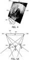
- an illustrative two -dimensional ultrasonic image 242is depicted showing a three-dimensional rendering of a needle 246 in accordance with one aspect of the disclosure.
- the needle 246is shown within image boundaries 244, but can be tracked outside of these boundaries 244.
- the rendering of needle 246is generated using trilateration as described above.
- the needle movementis tracked and displayed along with surrounding tissues in real-time.
- the present principlespermit fast and accurate imaging with a relatively inexpensive setup.
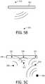
- FIGS. 5A-5Cwill describe beamforming techniques. Beamforming can spatially shift the origin of spheres (for times of flight) from physical array elements to virtual array elements. By focusing several physical elements into one location in space (using appropriate time delays), the focus location becomes a virtual element.
- a transducer array 302includes physical elements 304, which transmit focused energy. Illustratively, beams intersect at focus locations 305, 306 and 307. These focus locations 305, 306 and 307 may be employed as sphere centers for performing time-of-flight trilateration computations.
- the focus locations 305, 306 and 307advantageously provide non-collinear virtual elements which can enable the use of a planar one-dimensional transducer array configuration 302.
- a tracking sensor 310 on a medical deviceacts as a receiver to receive the energy from the virtual elements (305, 306 and 307) to perform position estimation as described.
- virtual elementsmay also be projected from behind a physical array 302.
- beamformingmay be employed to project a virtual element 312 which is on an opposite side of the array 302 from that of the sensor 310 attached to the medical device.
- a device element 320functions as a transmitter and virtual elements 322, 323 and 324 function as receivers.
- the virtual elements 322, 323 and 324correspond with physical elements 326 in a physical array 328.
- the physical elements 326receive signals transmitted from the device element 320.
- the signal delays measured at the physical elements 326are transformed to enable measurements from the perspective of the virtual elements 322, 323 and 324. In so doing, beamforming is employed to eliminate collinearity between physical elements 326.
- a block/flow diagramshows a method for imaging a medical device in accordance with one illustrative aspect of the disclosure.
- a medical deviceis introduced into a subject.
- the medical deviceincludes at least one element for exchanging signals.
- the medical devicemay include at least one of a needle, a catheter, a probe, a robot, a filter device, an electrode, etc.
- signalsare generated by an energy source and exchanged between the at least one element on the medical device and a plurality of transducers arranged in an array.
- the arraymay be a one-dimensional array (with linear elements) or a curved or staggered array (two-dimensional).
- times of flight of the signals between the transducers and the at least one elementare determined. This may include measuring the time that a pulse or signal from the transducers is received at the at least one element (or vice versa).
- a true intersection pointis determined for spheres having radii defined by the times of flight.
- the true intersection pointis imaged over time along with the subject to track a position of the medical device.
- the trilaterationis employed to determine the true intersection point in block 412.
- the array of transducersmay be disposed in a one dimensional array along a line or curved surface.
- the imagingmay include imaging the medical devices in three-dimensions using trilateration of the at least one element relative to at least three transducers.
- an additional element/transducermay be configured to distinguish between the true intersection point and a symmetric intersection point. This may include adding the transducer at a location where the true and symmetric intersections can be distinguished. Other techniques for distinguishing the intersection points may also be employed.
- the time-of-flight spherespreferably have centers that are non-collinear relative to the at least one sensor.
- beamformingmay be employed for transmitted signals from one or more transmitters to provide a new origin for the transmitted signal and eliminate the collinearity.
Landscapes
- Health & Medical Sciences (AREA)
- Life Sciences & Earth Sciences (AREA)
- Engineering & Computer Science (AREA)
- Surgery (AREA)
- Animal Behavior & Ethology (AREA)
- Veterinary Medicine (AREA)
- Biomedical Technology (AREA)
- Heart & Thoracic Surgery (AREA)
- Medical Informatics (AREA)
- Molecular Biology (AREA)
- Nuclear Medicine, Radiotherapy & Molecular Imaging (AREA)
- General Health & Medical Sciences (AREA)
- Public Health (AREA)
- Physics & Mathematics (AREA)
- Biophysics (AREA)
- Pathology (AREA)
- Radiology & Medical Imaging (AREA)
- Gynecology & Obstetrics (AREA)
- Robotics (AREA)
- Computer Vision & Pattern Recognition (AREA)
- Hematology (AREA)
- Ultra Sonic Daignosis Equipment (AREA)
Description
- This disclosure relates to medical devices and procedures, and more particularly to systems and methods for medical device localization in three dimensions using one or two-dimensional imaging probes.
- Needle insertion under ultrasound guidance is commonly performed,e.g., for biopsies, fluid drainage, nerve blocks, vascular access, etc. Needle visualization techniques have been successfully implemented based on steering imaging beams approximately perpendicular to the needle shaft (using, e.g., needle visualization enhancement software).
- In a significant number of cases, the needle deviates from the imaging plane due to tissue heterogeneities and bevel asymmetry. An out-of-plane needle disappears no matter how smart needle visualization enhancement software is, because the needle receives no ultrasound energy at all. A clinician then has to move the imaging transducer to find the needle and usually loses an original target plane. Furthermore, the clinician does not know where the needle is in relation to the imaging plane and therefore has no indication of how to move the transducer to find the needle.
- European Patent Application
EP 1 245 191 , entitled "Method of and imaging ultrasound system for determining the position of a catheter" to Torsten Solf et al. relates to an ultrasound transducer and an image processing unit for the acquisition of a three-dimensional ultrasound image of the body of a patient. - A document "Time of Flight and FMCW Catheter Localization," by Jay Mung et al., Ultrasonics Symposium (IUS), 2009 IEEE International, IEEE, Piscataway, NJ, USA, 20 September 2009, pp 590 - 593 relates to using ultrasound signals to track the 3D location of a catheter.
- The invention is defined by the claims.
- In accordance with the present principles, an imaging system and method include a medical device having a tracking element mounted thereon. An array of transducers has the transducers spaced apart from one another for exchanging energy in a subject between the tracking element and the array of transducers. A trilateration module is configured to interpret signals sensed between tracking element and the array of transducers to compute times of flight of signals associated with the transducers in the array such that a position of tracking element is determined in at least two dimensions to locate a position of the medical device in a visual image.
- These and other objects, features and advantages of the present disclosure will become apparent from the following detailed description, which is to be read in connection with the accompanying drawings.
- In the following figures:
FIG. 1 is a block/flow diagram showing a system/method for imaging a medical device in accordance with one illustrative aspect of the disclosure;FIG. 2A is a diagram showing a side-view of time-of-flight spheres emanating from transducer array elements of a probe in accordance with one illustrative aspect of the disclosure;FIG. 2B is a diagram showing a front-view of the time-of-flight spheres emanating from array elements of the probe and showing true and symmetric intersection points in accordance with one illustrative aspect of the disclosure;FIG. 3 is a perspective view showing three spheres intersecting to demonstrate trilateration in accordance with the present principles;FIG. 4 is a two-dimensional ultrasound image having a three-dimensional rendering of a needle in accordance with the present principles;FIG. 5A is a schematic diagram showing elements of a physical array focused/beamformed to form virtual transmitter elements in accordance with one aspect of the disclosure;FIG. 5B is a schematic diagram showing a virtual element formed behind a physical array in accordance with another aspect of the disclosure;FIG. 5C is a schematic diagram showing elements of a physical array beamformed to form virtual receiver elements based on signal delays in accordance with another aspect of the disclosure; andFIG. 6 is a block/flow diagram showing a system/method for imaging a medical device in accordance with another illustrative aspect of the disclosure.- In accordance with the present principles, a target plane, a relative position and trajectory of a medical device (e.g., with respect to a target anatomy of the target plane) need to be imaged at the same time to avoid issues related to losing an out-of-plane needle image during a procedure. One-dimensional (1D) ultrasound probes are used for two-dimensional (2D) visualization of needles with respect to the anatomy in a wide range of clinical interventions. However the position of the needle or tool cannot be assessed when the needle or tool lies outside of the imaging plane. The present systems and methods are provided for tracking and visualizing out-of-plane needles without losing the target anatomy image. In one aspect of the disclosure, this is achieved using a simple one-dimensional (1D) probe (for 2D imaging) or using a two-dimensional (2D) probe for 3D imaging. Methods for assessing the 3D position of a needle with respect to the imaging plane using a 1D array are also provided.
- An ultrasound element (passive or active) is embedded in a tracked tool, e.g., at a tip of the tool. Ultrasound signal times-of-flight between the tracked element and multiple elements of the imaging probe are used in a three-dimensional (3D) triangulation or trilateration routine to yield the position of the tracked element. As a result, ultrasound-guided needle interventions are greatly facilitated, without the need for expensive additional equipment (e.g., matrix arrays).
- It also should be understood that the present invention will be described in terms of medical instruments; however, the teachings of the present invention are much broader and are applicable to any instruments employed in tracking or analyzing complex biological or mechanical systems. In particular, the present principles are applicable to internal tracking procedures of biological systems, procedures in all areas of the body such as the lungs, gastrointestinal tract, excretory organs, blood vessels, etc. The elements depicted in the FIGS. may be implemented in various combinations of hardware and software and provide functions which may be combined in a single element or multiple elements.
- The functions of the various elements shown in the FIGS. can be provided through the use of dedicated hardware as well as hardware capable of executing software in association with appropriate software. When provided by a processor, the functions can be provided by a single dedicated processor, by a single shared processor, or by a plurality of individual processors, some of which can be shared. Moreover, explicit use of the term "processor" or "controller" should not be construed to refer exclusively to hardware capable of executing software, and can implicitly include, without limitation, digital signal processor ("DSP") hardware, read-only memory ("ROM") for storing software, random access memory ("RAM"), non-volatile storage, etc.
- Furthermore, aspects of the disclosure can take the form of a computer program product accessible from a computer-usable or computer-readable storage medium providing program code for use by or in connection with a computer or any instruction execution system. For the purposes of this description, a computer-usable or computer readable storage medium can be any apparatus that may include, store, communicate, propagate, or transport the program for use by or in connection with the instruction execution system, apparatus, or device. The medium can be an electronic, magnetic, optical, electromagnetic, infrared, or semiconductor system (or apparatus or device) or a propagation medium. Examples of a computer-readable medium include a semiconductor or solid state memory, magnetic tape, a removable computer diskette, a random access memory (RAM), a read-only memory (ROM), a rigid magnetic disk and an optical disk. Current examples of optical disks include compact disk - read only memory (CD-ROM), compact disk - read/write (CD-R/W) and DVD.
- Referring now to the drawings in which like numerals represent the same or similar elements and initially to
FIG. 1 , asystem 100 for performing a medical procedure is illustratively depicted.System 100 may include a workstation orconsole 112 from which a procedure is supervised and managed. Procedures may include any procedure including but not limited to biopsies, ablations, injection of medications etc.Workstation 112 preferably includes one ormore processors 114 andmemory 116 for storing programs and applications. It should be understood that the function and components ofsystem 100 may be integrated into one or more workstations or systems. Memory 116 may store adevice sensing module 115 configured to interpret electromagnetic, optical and/or acoustic feedback signals from amedical device 102. Thesensing module 115 is configured to use the signal feedback (and any other feedback) to provide a location or to depict themedical device 102 in medical images. Themedical device 102 may include, e.g., a needle, a catheter, a guide wire, an endoscope, a probe, a robot, an electrode, a filter device, a balloon device or other medical component, etc.Workstation 112 may include adisplay 118 for viewing internal images of a subject using animaging system 110. Theimaging system 110 may include imaging modalities such as ultrasound, fluoroscopy, photoacoustics, etc. Theimaging system 110 may also include, e.g., a magnetic resonance imaging (MRI) system, a fluoroscopy system, a computed tomography (CT) system, an ultrasound system or other system.Display 118 may also permit a user to interact with theworkstation 112 and its components and functions. This is further facilitated by aninterface 120 which may include a keyboard, mouse, a joystick or any other peripheral or control to permit user interaction with theworkstation 112.- One or more sensors/
transducers 106 may be incorporated into the device(s) 102, so tracking information from anenergy source 125 can be detected at the device(s) 102. - It should be understood that while the present illustrative example will be described in terms of a tracked element 106 (on the device 102) being a receiver while tracking elements or transducers 107 (of an imaging array 109) are transmitters, the opposite configuration may also be provided. For example, the same times-of-flight may be measured by using the tracked element 106 (on the device 102) as a transmitter, and the tracking elements/transducers 107 (of the array 109) may act as receivers.
- The
energy source 125 need not be provided from a source external to a body/subject 148, and may be from an internal source or from anotherimaging device 110. In oneaspect of the disclosure, the energy source is an ultrasonic source. The sensors/elements 106 may be employed to detect electromagnetic energy or acoustic energy (or transmit the energy). This permits the exchange of energy which will be used to interpret a position and/or orientation of thedevice 102. The signals will be employed as feedback to make adjustments or otherwise perform the medical procedure. Thetransducers 107 may include an ultrasonic sensor or sensors (disposed in a probe) or other sensor or transmission devices. Imaging system 110 may be provided to collect real-time intra-operative imaging data. The imaging data may be displayed ondisplay 118.Sensing module 115 may determine positions of the sensors/elements 106 and therefore thedevice 102 within the real-time images based upon energy measured by the sensors/elements 106. This may include employing a trilateration or triangulation method/module 104 as will be described herein. A digital rendering of the medical device 102 (using feedback signals) can be displayed to realize the position of thedevice 102 against the real-time images (tracking). The digital rendering may be generated by an image processing module 117.- It should be understood that tracking and imaging using an ultrasonic system may occur concurrently or sequentially. In preferred aspects of the disclosure, an imaging array of transducers is the same as the tracking array of transducers. It is possible to use the imaging beams to track and vice versa (use the tracking beams to image). However, the tracking beams as described herein may not be suitable for ultrasound imaging. In such cases, imaging frames and tracking frames may be interleaved (alternated). If the tracked element is a transmitter, then either its bandwidth needs to be separate from that of the imaging pulses, or scanning may be interrupted during reception of the signals from the tracked element. Other techniques may also be employed to ensure both operations (e.g., tracking and imaging) are performed in real-time.
- In one aspect of the disclosure, the
imaging system 110 includes an ultrasonic system, and the emissions are acoustic in nature. In this case, the sensor(s) 106 include ultrasonic sensors which detect acoustic signals generated byultrasonic transducers 107 arranged in anarray 109 on anultrasonic probe 111. In this way, both anatomical images and device images can concurrently be displayed. - In another useful aspect of the disclosure, an interventional application includes the use of two or more medical devices inside of a subject 148. For example, one
device 102 may include a guide catheter, which is placed at one point, and anotherdevice 102 may include a needle for performing an ablation or biopsy at fixed/different points along the length of the catheter. Other combinations of devices are also contemplated. - In accordance with one particularly useful aspect of the disclosure, one or
several ultrasound sensors 106 are mounted on a tracked tool ordevice 102. Thetool 102 is tracked using thesensor 106 for tracking the position of thedevice 102. A1D imaging array 109 is provided for imaging thetool 102 in accordance with thesensors 106. Thearray 109 may include a line of transducers (receivers or transmitters) 107 to form the 1Ddimensional array 109. The one dimensional array may include a straight arrangement (line) oftransducers 107 or may includetransducers 107 disposed on a curved path (arc). - In one aspect of the disclosure, a physically planar array may be employed using beamforming techniques to spatially shift an origin of a time-of-flight sphere emanating from the
physical array elements 107. By focusing several physical elements into one location in space (using appropriate time delays) the focus location becomes a virtual element. - The
sensing module 115 includes a three-dimensional (3D) trilateration routine that tracks theultrasound elements 106 aboard thetool 102. In one aspect of the disclosure, thedisplay 118 provides a 3D rendering of the trackedtool 102 superimposed on a 2D ultrasound image. The position of thetool 102 will be determined as illustratively described with reference toFIGS. 2A-2B . - Referring to
FIGS. 2A and 2B , diagrams show a tracked tool 206 (e.g., a needle) having an element 208 (e.g., an ultrasonic element for transmitting or receiving) at its tip depicted in the vicinity of a curved array (2D probe or a 1D array)ultrasonic probe 220 having a plurality of ultrasound (US) transducers or elements 222 (for transmitting or receiving). In accordance with the present principles, a 3D position of thetool 206 with respect to an imaging plane is assessed using the 1D array oftransducers 222 in theprobe 220. The ultrasound element 208 (passive or active) is embedded in the trackedtool 206, for example, at its tip. Ultrasound signal times-of-flight between the trackedelement 208 and themultiple transducers 222 of theimaging probe 220 are used in a 3D triangulation or trilateration routine (104 inFIG. 1 ) to yield the position of the trackedelement 208. It should be understood that a plurality ofelements 208 may be employed on thetool 206. Each sensor's position may be tracked using the present principles to describe its position during a procedure. - Time-of-flight trilateration of ultrasound signals between the tracked
element 208 andseveral transducers 222 of the imaging array can yield 3D positioning as long as theimaging array transducers 222 used are not collinear relative to theelement 208. The position of the trackedelement 208 is at an intersection of at least threespheres element 208 and thetracking transducers 222. The intersection of threespheres true intersection 231 and a symmetric intersection 232) as long as the three spheres' centers are not collinear with respect to the tracked element 208 (the intersection of two spheres are a circle, the intersection of the last sphere with the circle yields two points). - Trilateration is employed to determine the position of the tracked
element 208 and therefore the needle ortool 206. Trilateration is the process of determining absolute or relative locations of points by measurement of distances, using the geometry of spheres or triangles. In contrast to triangulation, it does not involve the measurement of angles although triangulation techniques may also be employed. - In two-dimensional space, using two reference points is normally sufficient to leave only two possibilities for the location determined, and the tie is broken by including a third reference point or other information. In three-dimensional space, using three reference points similarly leaves only two possibilities, and the tie is broken by including a fourth reference point or other information.
- Referring to
FIG. 3 , a solution is found by formulating equations for the threesphere surfaces 


- First, we subtract the second equation from the first and solve for x:


- Now we have the solution forx,y andz. Becausez is expressed as the positive or negative square root, it is possible for there to be zero, one or two solutions to the problem. This can be visualized as taking a
circle 234 found from intersecting a first 226 andsecond sphere 230 and intersecting that with athird sphere 228. If thatcircle 234 falls entirely outside or inside of thesphere 228, z is equal to the square root of a negative number: no real solution exists. If thatcircle 234 touches thesphere 228 on exactly one point, z is equal to zero. If thatcircle 234 touches the surface of the sphere at two points, then z is equal to plus or minus the square root of a positive number (as depicted inFIG. 3 ). - Referring again to
FIGS. 2A and 2B , it is now possible to map the 3D position of the trackedelement 208 with a 1D curvilinear imaging array (222). With a linear array where elements are collinear, transmit or receive focusing can generate virtual transducers in the array that would no longer be aligned, so that the technique is also applicable to linear arrays with some beamforming. Beamforming in effect moves an origin of a sphere by moving the origin of a transmitted signal to a new location. - There may be uncertainty since the trilateration yields two positions (symmetric with respect to the imaged plane). This uncertainty can be broken using a priori knowledge, or by gently rocking the
ultrasound probe 220 and observing the relative movement of the tracked element 208 (getting closer or farther relative to the target plane). Also, a single additional imaging sensor, transducer or element 236 (or transmitter) may also be employed on a side of theimaging array 222 to break the uncertainty (tie-breaker). - The present technique can detect the tracked
elements 208 if theelements 208 are within aplane thickness 238, that is, near an imaging plane. Customized probe design (with little elevation focusing to generate a compromise between image quality and tracking field-of-view) may be employed to extend the functionality of the system for specific applications. - In conventional systems, if a one-dimensional (1D) ultrasound (US) probe is employed for 2D visualization of needles or other tools, the position of the tool cannot be assessed for imaging when the tool lies outside of an US imaging plane 239. Two-dimensional (2D) ultrasound probes (1D curved arrays) may be employed for 2D visualization of needles with respect to a patient's anatomy in a wide range of clinical interventions. In conventional systems, clinicians spend a considerable amount of time orienting the needle fully inside the plane to visualize the needle. From oblique/orthogonal injections, the needle is very difficult to visualize. However, in accordance with the present principles, the needle or tool can be located and imaged in three dimensions while also displaying the target area. In this way, the needle is easy to find and its position accurately tracked for any type of procedure, such as, ultrasound-guided needle interventions, e.g., nerve blocks, biopsies, vascular access, abcess drainage, ablation, etc. US-guided needle interventions are greatly facilitated, without the need for expensive additional equipment (matrix arrays). US-guided interventions become (i) more accurate; (ii) faster and (iii) inexpensive (by using 2D probes).
- Referring to
FIG. 4 , an illustrative two -dimensionalultrasonic image 242 is depicted showing a three-dimensional rendering of aneedle 246 in accordance with one aspect of the disclosure. Theneedle 246 is shown withinimage boundaries 244, but can be tracked outside of theseboundaries 244. The rendering ofneedle 246 is generated using trilateration as described above. The needle movement is tracked and displayed along with surrounding tissues in real-time. The present principles permit fast and accurate imaging with a relatively inexpensive setup. FIGS. 5A-5C will describe beamforming techniques. Beamforming can spatially shift the origin of spheres (for times of flight) from physical array elements to virtual array elements. By focusing several physical elements into one location in space (using appropriate time delays), the focus location becomes a virtual element.- Referring to
FIG. 5A , atransducer array 302 includesphysical elements 304, which transmit focused energy. Illustratively, beams intersect atfocus locations locations focus locations transducer array configuration 302. In this configuration, atracking sensor 310 on a medical device acts as a receiver to receive the energy from the virtual elements (305, 306 and 307) to perform position estimation as described. - Referring to
FIG. 5B , virtual elements may also be projected from behind aphysical array 302. For example, beamforming may be employed to project avirtual element 312 which is on an opposite side of thearray 302 from that of thesensor 310 attached to the medical device. - Referring to
FIG. 5C , in this aspect of the disclosure, a device element 320 functions as a transmitter andvirtual elements virtual elements physical elements 326 in aphysical array 328. Thephysical elements 326 receive signals transmitted from the device element 320. The signal delays measured at thephysical elements 326 are transformed to enable measurements from the perspective of thevirtual elements physical elements 326. - Referring to
FIG. 6 , a block/flow diagram shows a method for imaging a medical device in accordance with one illustrative aspect of the disclosure. Inblock 402, a medical device is introduced into a subject. The medical device includes at least one element for exchanging signals. The medical device may include at least one of a needle, a catheter, a probe, a robot, a filter device, an electrode, etc. - In
block 404, signals are generated by an energy source and exchanged between the at least one element on the medical device and a plurality of transducers arranged in an array. The array may be a one-dimensional array (with linear elements) or a curved or staggered array (two-dimensional). Inblock 406, times of flight of the signals between the transducers and the at least one element are determined. This may include measuring the time that a pulse or signal from the transducers is received at the at least one element (or vice versa). - In
block 408, a true intersection point is determined for spheres having radii defined by the times of flight. Inblock 410, the true intersection point is imaged over time along with the subject to track a position of the medical device. The trilateration is employed to determine the true intersection point inblock 412. Inblock 414, the array of transducers may be disposed in a one dimensional array along a line or curved surface. The imaging may include imaging the medical devices in three-dimensions using trilateration of the at least one element relative to at least three transducers. - In
block 416, an additional element/transducer may be configured to distinguish between the true intersection point and a symmetric intersection point. This may include adding the transducer at a location where the true and symmetric intersections can be distinguished. Other techniques for distinguishing the intersection points may also be employed. - In
block 418, the time-of-flight spheres preferably have centers that are non-collinear relative to the at least one sensor. However, in the event that the spheres are collinear, beamforming may be employed for transmitted signals from one or more transmitters to provide a new origin for the transmitted signal and eliminate the collinearity.


Claims (9)
- A workstation, comprising:an imaging probe (111) having an array (109) of transducers spaced apart from one another for exchanging energy with a tracked medical device (102) in a subject;a processor (114); andmemory (116) coupled to the processor,characterized by the memory including a trilateration module (104) configured to receive signals and, in conjunction with the processor, compute times of flight of signals for the transducers in the array relative to at least one tracking element on the tracked medical device such that a position of the at least one tracking element is determined in at least two dimensions such that an image of the medical device and the subject are concurrently provided in a visual image;wherein for a linear array of transducers, the signals from the transducers are beamformed to generate virtual transducers which are non-collinear relative to the at least one tracking element.
- The workstation as recited in claim 1, wherein the array (109) of transducers are disposed in a one dimensional array along a line or an arc.
- The workstation as recited in claim 1, wherein the array (109) of transducers includes ultrasonic transducers and the at least one tracking element (106) includes an ultrasonic transducer element.
- The workstation as recited in claim 1, wherein the trilateration module (104) determines the position of the at least one tracking element by finding a true intersection point between spheres (226, 228, 230) having radii defined by times of flight from the transducers.
- The workstation as recited in claim 4, wherein the spheres (226, 228, 230) have centers that are non-collinear relative to the at least one tracking element.
- The workstation as recited in claim 1, further comprising an additional transducer (236) configured to provide information to distinguish between a true intersection point and a symmetric intersection point.
- The workstation as recited in claim 1, wherein the at least two dimensions include three dimensions such that a three-dimensional image of the medical device is tracked in a two-dimensional image.
- An imaging system, comprising:a medical device (102) having at least one tracking element (106) mounted thereon anda workstation as claimed in claim 1 to track the medical device in a visual image.
- The system as recited in claim 8, wherein the medical device (102) includes at least one of a needle, a catheter, a probe and an electrode.
Applications Claiming Priority (2)
| Application Number | Priority Date | Filing Date | Title |
|---|---|---|---|
| US201161496077P | 2011-06-13 | 2011-06-13 | |
| PCT/IB2012/052830WO2012172458A1 (en) | 2011-06-13 | 2012-06-06 | Three-dimensional needle localization with a two-dimensional imaging probe |
Publications (2)
| Publication Number | Publication Date |
|---|---|
| EP2717772A1 EP2717772A1 (en) | 2014-04-16 |
| EP2717772B1true EP2717772B1 (en) | 2021-05-26 |
Family
ID=46331655
Family Applications (1)
| Application Number | Title | Priority Date | Filing Date |
|---|---|---|---|
| EP12729236.5AActiveEP2717772B1 (en) | 2011-06-13 | 2012-06-06 | Three-dimensional needle localization with a two-dimensional imaging probe |
Country Status (5)
| Country | Link |
|---|---|
| US (1) | US11147532B2 (en) |
| EP (1) | EP2717772B1 (en) |
| JP (1) | JP6053766B2 (en) |
| CN (1) | CN103747729B (en) |
| WO (1) | WO2012172458A1 (en) |
Families Citing this family (35)
| Publication number | Priority date | Publication date | Assignee | Title |
|---|---|---|---|---|
| EP2770344B1 (en)* | 2013-02-21 | 2015-09-09 | Sercel | Method and device for estimating a relative position between towed acoustic linear antennas |
| WO2014138216A1 (en)* | 2013-03-05 | 2014-09-12 | Kafiluddi Ronny | Compound needle |
| WO2014139005A1 (en)* | 2013-03-15 | 2014-09-18 | Colibri Technologies Inc. | Active localization and visualization of minimally invasive devices using ultrasound |
| GB201307551D0 (en) | 2013-04-26 | 2013-06-12 | Ucl Business Plc | A method and apparatus for determining the location of a medical instrument with respect to ultrasound imaging and a medical instrument |
| EP3019088B1 (en)* | 2013-07-08 | 2020-12-02 | Koninklijke Philips N.V. | Imaging apparatus for biopsy or brachytherapy |
| EP3024548B1 (en)* | 2013-07-23 | 2020-10-21 | Koninklijke Philips N.V. | System for localizing body structures |
| CN105578984B (en)* | 2013-09-24 | 2021-02-26 | 皇家飞利浦有限公司 | Acoustic 3D tracking of interventional tools |
| RU2689176C2 (en)* | 2014-01-02 | 2019-05-24 | Конинклейке Филипс Н.В. | Orientation and tracking of tool position relative to ultrasound image plane |
| WO2015155632A1 (en)* | 2014-04-11 | 2015-10-15 | Koninklijke Philips N.V. | Needle with multiple sensors |
| JP6014643B2 (en)* | 2014-10-15 | 2016-10-25 | 株式会社日立製作所 | Ultrasonic diagnostic equipment |
| US10905396B2 (en)* | 2014-11-18 | 2021-02-02 | C. R. Bard, Inc. | Ultrasound imaging system having automatic image presentation |
| WO2016081321A2 (en)* | 2014-11-18 | 2016-05-26 | C.R. Bard, Inc. | Ultrasound imaging system having automatic image presentation |
| CN106999149B (en)* | 2014-11-25 | 2020-09-29 | 皇家飞利浦有限公司 | Multi-sensor ultrasound probe and related methods |
| EP3236859B1 (en)* | 2014-12-24 | 2021-03-31 | Koninklijke Philips N.V. | Needle trajectory prediction for target biopsy |
| CN108474837A (en) | 2015-12-22 | 2018-08-31 | 皇家飞利浦有限公司 | Tracking based on ultrasound |
| JP6668817B2 (en)* | 2016-02-26 | 2020-03-18 | コニカミノルタ株式会社 | Ultrasound diagnostic apparatus and control program |
| CN109073751B (en)* | 2016-04-19 | 2023-10-13 | 皇家飞利浦有限公司 | Probes, systems and methods for acoustic registration |
| US11369340B2 (en)* | 2016-09-30 | 2022-06-28 | Koninklijke Philips N.V. | Tracking a feature of an interventional device |
| WO2018087111A1 (en)* | 2016-11-08 | 2018-05-17 | Koninklijke Philips N.V. | System and method for tracking an interventional instrument with feedback concerning tracking reliability |
| EP3592240B1 (en) | 2017-03-10 | 2021-05-12 | Koninklijke Philips N.V. | Location system for locating an acoustic sensor |
| EP3642646B1 (en) | 2017-06-19 | 2025-02-19 | Koninklijke Philips N.V. | Interleaved imaging and tracking sequences for ultrasound-based instrument tracking |
| JP7229240B2 (en) | 2017-11-14 | 2023-02-27 | コーニンクレッカ フィリップス エヌ ヴェ | Ultrasound vascular navigation device, system and method |
| CN111757704B (en)* | 2018-02-22 | 2025-01-17 | 皇家飞利浦有限公司 | Interventional medical device tracking |
| EP3787520B1 (en) | 2018-05-04 | 2024-09-25 | Hologic, Inc. | Biopsy needle visualization |
| US12121304B2 (en) | 2018-05-04 | 2024-10-22 | Hologic, Inc. | Introducer and localization wire visualization |
| CN112312840A (en)* | 2018-06-22 | 2021-02-02 | 皇家飞利浦有限公司 | Intravascular ultrasound location identification |
| WO2020002620A1 (en)* | 2018-06-29 | 2020-01-02 | Koninklijke Philips N.V. | Biopsy prediction and guidance with ultrasound imaging and associated devices, systems, and methods |
| DE102018215470A1 (en)* | 2018-09-12 | 2020-03-12 | B. Braun Melsungen Ag | Method for determining the position of a medical invasive component and medical system for executing such a method |
| WO2020135945A1 (en)* | 2018-11-14 | 2020-07-02 | Robeaute | System and method for real-time localization |
| JP7168474B2 (en)* | 2019-01-31 | 2022-11-09 | 富士フイルムヘルスケア株式会社 | ULTRASOUND IMAGING DEVICE, TREATMENT ASSISTANCE SYSTEM, AND IMAGE PROCESSING METHOD |
| EP3771435A1 (en)* | 2019-07-31 | 2021-02-03 | Koninklijke Philips N.V. | Passive-ultrasound-sensor-based initialization for image-based device segmentation |
| US11998285B2 (en) | 2019-12-04 | 2024-06-04 | Gyrus Acmi, Inc. | Surgical guiding probe |
| US11228469B1 (en)* | 2020-07-16 | 2022-01-18 | Deeyook Location Technologies Ltd. | Apparatus, system and method for providing locationing multipath mitigation |
| EP4258999B8 (en)* | 2020-12-11 | 2025-05-28 | Robeaute | Micro-device tracking and vizualisation system |
| US20240358384A1 (en)* | 2023-04-26 | 2024-10-31 | Applaud Medical, Inc. | Medical Device With Acoustic Sensor(s) and Method for Localizing Medical Device and Acoustic Source |
Family Cites Families (31)
| Publication number | Priority date | Publication date | Assignee | Title |
|---|---|---|---|---|
| US6246898B1 (en)* | 1995-03-28 | 2001-06-12 | Sonometrics Corporation | Method for carrying out a medical procedure using a three-dimensional tracking and imaging system |
| US6216540B1 (en)* | 1995-06-06 | 2001-04-17 | Robert S. Nelson | High resolution device and method for imaging concealed objects within an obscuring medium |
| US5830145A (en) | 1996-09-20 | 1998-11-03 | Cardiovascular Imaging Systems, Inc. | Enhanced accuracy of three-dimensional intraluminal ultrasound (ILUS) image reconstruction |
| JPH10277040A (en)* | 1997-04-09 | 1998-10-20 | Hitachi Medical Corp | Ultrasonic diagnostic device |
| GB2329709B (en) | 1997-09-26 | 2001-12-19 | Roke Manor Research | Catheter localisation system |
| GB2331365B (en)* | 1997-11-15 | 2002-03-13 | Roke Manor Research | Catheter tracking system |
| US6120453A (en)* | 1997-11-17 | 2000-09-19 | Sharp; William A. | Three-dimensional ultrasound system based on the coordination of multiple ultrasonic transducers |
| DE10115341A1 (en)* | 2001-03-28 | 2002-10-02 | Philips Corp Intellectual Pty | Method and imaging ultrasound system for determining the position of a catheter |
| US6592520B1 (en)* | 2001-07-31 | 2003-07-15 | Koninklijke Philips Electronics N.V. | Intravascular ultrasound imaging apparatus and method |
| JP2003101861A (en)* | 2001-09-21 | 2003-04-04 | Sanyo Electric Co Ltd | Digital camera |
| US6896657B2 (en) | 2003-05-23 | 2005-05-24 | Scimed Life Systems, Inc. | Method and system for registering ultrasound image in three-dimensional coordinate system |
| US7207942B2 (en)* | 2003-07-25 | 2007-04-24 | Siemens Medical Solutions Usa, Inc. | Adaptive grating lobe suppression in ultrasound imaging |
| US20050062469A1 (en)* | 2003-09-23 | 2005-03-24 | Anderson Peter Traneus | System and method for hemisphere disambiguation in electromagnetic tracking systems |
| US7713210B2 (en)* | 2004-11-23 | 2010-05-11 | St. Jude Medical, Atrial Fibrillation Division, Inc. | Method and apparatus for localizing an ultrasound catheter |
| US20070213616A1 (en)* | 2005-10-20 | 2007-09-13 | Thomas Anderson | Systems and methods for arteriotomy localization |
| US20070167823A1 (en) | 2005-12-20 | 2007-07-19 | General Electric Company | Imaging catheter and method for volumetric ultrasound |
| US20070161905A1 (en) | 2006-01-12 | 2007-07-12 | Gynesonics, Inc. | Intrauterine ultrasound and method for use |
| US8317712B2 (en) | 2006-05-12 | 2012-11-27 | Koninklijke Philips Electronics N.V. Eindhoven | Retrospective dynamic transmit focusing for spatial compounding |
| US7621169B2 (en)* | 2006-10-26 | 2009-11-24 | General Electric Company | Systems and methods for integrating a navigation field replaceable unit into a fluoroscopy system |
| WO2009032421A2 (en) | 2007-07-27 | 2009-03-12 | Meridian Cardiovascular Systems, Inc. | Image guided intracardiac catheters |
| US20110112403A1 (en)* | 2008-07-11 | 2011-05-12 | Barnev Ltd. | Method and a system for monitoring, contractions and/or a birth process and/or the progress and/or position of a fetus |
| US20100210943A1 (en)* | 2009-02-18 | 2010-08-19 | West Virginia University Research Corporation | Systems and Methods for Echoperiodontal Imaging |
| JP4776707B2 (en)* | 2009-03-30 | 2011-09-21 | 株式会社東芝 | Ultrasonic imaging device |
| JP5665040B2 (en)* | 2009-09-10 | 2015-02-04 | 学校法人上智学院 | Displacement measuring method and apparatus, and ultrasonic diagnostic apparatus |
| US9282946B2 (en)* | 2010-05-03 | 2016-03-15 | Koninklijke Philips N.V. | Ultrasonic tracking of ultrasound transducer(s) aboard an interventional tool |
| WO2012024201A1 (en)* | 2010-08-19 | 2012-02-23 | Mayo Foundation For Medical Education And Research | Steerable catheter navigation with the use of interference ultrasonography |
| WO2012066430A1 (en)* | 2010-11-18 | 2012-05-24 | Koninklijke Philips Electronics N.V. | Medical device with ultrasound transducers embedded in flexible foil |
| US10617374B2 (en)* | 2011-01-28 | 2020-04-14 | Medtronic Navigation, Inc. | Method and apparatus for image-based navigation |
| WO2013116809A1 (en)* | 2012-02-03 | 2013-08-08 | Los Alamos National Security, Llc | Ultrasound waveform tomography with tv regularization |
| CN104936517B (en)* | 2013-03-09 | 2020-06-05 | 科纳医药股份有限公司 | Transducers, systems, and fabrication techniques for focused ultrasound therapy |
| WO2014139005A1 (en)* | 2013-03-15 | 2014-09-18 | Colibri Technologies Inc. | Active localization and visualization of minimally invasive devices using ultrasound |
- 2012
- 2012-06-06WOPCT/IB2012/052830patent/WO2012172458A1/enactiveApplication Filing
- 2012-06-06USUS14/118,244patent/US11147532B2/enactiveActive
- 2012-06-06CNCN201280039408.9Apatent/CN103747729B/enactiveActive
- 2012-06-06EPEP12729236.5Apatent/EP2717772B1/enactiveActive
- 2012-06-06JPJP2014515313Apatent/JP6053766B2/ennot_activeExpired - Fee Related
Non-Patent Citations (1)
| Title |
|---|
| None* |
Also Published As
| Publication number | Publication date |
|---|---|
| EP2717772A1 (en) | 2014-04-16 |
| WO2012172458A1 (en) | 2012-12-20 |
| US11147532B2 (en) | 2021-10-19 |
| CN103747729B (en) | 2016-07-13 |
| JP6053766B2 (en) | 2016-12-27 |
| US20140094695A1 (en) | 2014-04-03 |
| JP2014516738A (en) | 2014-07-17 |
| CN103747729A (en) | 2014-04-23 |
Similar Documents
| Publication | Publication Date | Title |
|---|---|---|
| EP2717772B1 (en) | Three-dimensional needle localization with a two-dimensional imaging probe | |
| US20220273258A1 (en) | Path tracking in ultrasound system for device tracking | |
| US11786318B2 (en) | Intelligent real-time tool and anatomy visualization in 3D imaging workflows for interventional procedures | |
| US11633171B2 (en) | Ultrasound based tracking system using triangulation and spatial positioning with detachable reference frame and ultrasound emitters | |
| US11604249B2 (en) | Interventional device recognition | |
| US20190298457A1 (en) | System and method for tracking an interventional instrument with feedback concerning tracking reliability | |
| EP3049013B1 (en) | Acoustic 3d tracking of interventional tool | |
| EP4013310B1 (en) | Ultrasound-based device localization | |
| Najafi et al. | A closed-form differential formulation for ultrasound spatial calibration | |
| Stoll et al. | Passive Markers for |
Legal Events
| Date | Code | Title | Description |
|---|---|---|---|
| PUAI | Public reference made under article 153(3) epc to a published international application that has entered the european phase | Free format text:ORIGINAL CODE: 0009012 | |
| 17P | Request for examination filed | Effective date:20140113 | |
| AK | Designated contracting states | Kind code of ref document:A1 Designated state(s):AL AT BE BG CH CY CZ DE DK EE ES FI FR GB GR HR HU IE IS IT LI LT LU LV MC MK MT NL NO PL PT RO RS SE SI SK SM TR | |
| DAX | Request for extension of the european patent (deleted) | ||
| STAA | Information on the status of an ep patent application or granted ep patent | Free format text:STATUS: EXAMINATION IS IN PROGRESS | |
| 17Q | First examination report despatched | Effective date:20190415 | |
| RAP1 | Party data changed (applicant data changed or rights of an application transferred) | Owner name:KONINKLIJKE PHILIPS N.V. | |
| GRAP | Despatch of communication of intention to grant a patent | Free format text:ORIGINAL CODE: EPIDOSNIGR1 | |
| STAA | Information on the status of an ep patent application or granted ep patent | Free format text:STATUS: GRANT OF PATENT IS INTENDED | |
| INTG | Intention to grant announced | Effective date:20201214 | |
| RIN1 | Information on inventor provided before grant (corrected) | Inventor name:VIGNON, FRANCOIS GUY GERARD MARIE Inventor name:JAIN, AMEET KUMAR | |
| GRAS | Grant fee paid | Free format text:ORIGINAL CODE: EPIDOSNIGR3 | |
| GRAA | (expected) grant | Free format text:ORIGINAL CODE: 0009210 | |
| STAA | Information on the status of an ep patent application or granted ep patent | Free format text:STATUS: THE PATENT HAS BEEN GRANTED | |
| AK | Designated contracting states | Kind code of ref document:B1 Designated state(s):AL AT BE BG CH CY CZ DE DK EE ES FI FR GB GR HR HU IE IS IT LI LT LU LV MC MK MT NL NO PL PT RO RS SE SI SK SM TR | |
| REG | Reference to a national code | Ref country code:GB Ref legal event code:FG4D | |
| REG | Reference to a national code | Ref country code:CH Ref legal event code:EP | |
| REG | Reference to a national code | Ref country code:DE Ref legal event code:R096 Ref document number:602012075675 Country of ref document:DE | |
| REG | Reference to a national code | Ref country code:AT Ref legal event code:REF Ref document number:1395388 Country of ref document:AT Kind code of ref document:T Effective date:20210615 | |
| REG | Reference to a national code | Ref country code:IE Ref legal event code:FG4D | |
| REG | Reference to a national code | Ref country code:LT Ref legal event code:MG9D | |
| REG | Reference to a national code | Ref country code:AT Ref legal event code:MK05 Ref document number:1395388 Country of ref document:AT Kind code of ref document:T Effective date:20210526 | |
| PG25 | Lapsed in a contracting state [announced via postgrant information from national office to epo] | Ref country code:HR Free format text:LAPSE BECAUSE OF FAILURE TO SUBMIT A TRANSLATION OF THE DESCRIPTION OR TO PAY THE FEE WITHIN THE PRESCRIBED TIME-LIMIT Effective date:20210526 Ref country code:BG Free format text:LAPSE BECAUSE OF FAILURE TO SUBMIT A TRANSLATION OF THE DESCRIPTION OR TO PAY THE FEE WITHIN THE PRESCRIBED TIME-LIMIT Effective date:20210826 Ref country code:AT Free format text:LAPSE BECAUSE OF FAILURE TO SUBMIT A TRANSLATION OF THE DESCRIPTION OR TO PAY THE FEE WITHIN THE PRESCRIBED TIME-LIMIT Effective date:20210526 Ref country code:FI Free format text:LAPSE BECAUSE OF FAILURE TO SUBMIT A TRANSLATION OF THE DESCRIPTION OR TO PAY THE FEE WITHIN THE PRESCRIBED TIME-LIMIT Effective date:20210526 Ref country code:LT Free format text:LAPSE BECAUSE OF FAILURE TO SUBMIT A TRANSLATION OF THE DESCRIPTION OR TO PAY THE FEE WITHIN THE PRESCRIBED TIME-LIMIT Effective date:20210526 | |
| REG | Reference to a national code | Ref country code:NL Ref legal event code:MP Effective date:20210526 | |
| PG25 | Lapsed in a contracting state [announced via postgrant information from national office to epo] | Ref country code:GR Free format text:LAPSE BECAUSE OF FAILURE TO SUBMIT A TRANSLATION OF THE DESCRIPTION OR TO PAY THE FEE WITHIN THE PRESCRIBED TIME-LIMIT Effective date:20210827 Ref country code:IS Free format text:LAPSE BECAUSE OF FAILURE TO SUBMIT A TRANSLATION OF THE DESCRIPTION OR TO PAY THE FEE WITHIN THE PRESCRIBED TIME-LIMIT Effective date:20210926 Ref country code:LV Free format text:LAPSE BECAUSE OF FAILURE TO SUBMIT A TRANSLATION OF THE DESCRIPTION OR TO PAY THE FEE WITHIN THE PRESCRIBED TIME-LIMIT Effective date:20210526 Ref country code:RS Free format text:LAPSE BECAUSE OF FAILURE TO SUBMIT A TRANSLATION OF THE DESCRIPTION OR TO PAY THE FEE WITHIN THE PRESCRIBED TIME-LIMIT Effective date:20210526 Ref country code:SE Free format text:LAPSE BECAUSE OF FAILURE TO SUBMIT A TRANSLATION OF THE DESCRIPTION OR TO PAY THE FEE WITHIN THE PRESCRIBED TIME-LIMIT Effective date:20210526 Ref country code:NO Free format text:LAPSE BECAUSE OF FAILURE TO SUBMIT A TRANSLATION OF THE DESCRIPTION OR TO PAY THE FEE WITHIN THE PRESCRIBED TIME-LIMIT Effective date:20210826 Ref country code:PL Free format text:LAPSE BECAUSE OF FAILURE TO SUBMIT A TRANSLATION OF THE DESCRIPTION OR TO PAY THE FEE WITHIN THE PRESCRIBED TIME-LIMIT Effective date:20210526 Ref country code:PT Free format text:LAPSE BECAUSE OF FAILURE TO SUBMIT A TRANSLATION OF THE DESCRIPTION OR TO PAY THE FEE WITHIN THE PRESCRIBED TIME-LIMIT Effective date:20210927 | |
| PG25 | Lapsed in a contracting state [announced via postgrant information from national office to epo] | Ref country code:NL Free format text:LAPSE BECAUSE OF FAILURE TO SUBMIT A TRANSLATION OF THE DESCRIPTION OR TO PAY THE FEE WITHIN THE PRESCRIBED TIME-LIMIT Effective date:20210526 | |
| PG25 | Lapsed in a contracting state [announced via postgrant information from national office to epo] | Ref country code:SM Free format text:LAPSE BECAUSE OF FAILURE TO SUBMIT A TRANSLATION OF THE DESCRIPTION OR TO PAY THE FEE WITHIN THE PRESCRIBED TIME-LIMIT Effective date:20210526 Ref country code:SK Free format text:LAPSE BECAUSE OF FAILURE TO SUBMIT A TRANSLATION OF THE DESCRIPTION OR TO PAY THE FEE WITHIN THE PRESCRIBED TIME-LIMIT Effective date:20210526 Ref country code:DK Free format text:LAPSE BECAUSE OF FAILURE TO SUBMIT A TRANSLATION OF THE DESCRIPTION OR TO PAY THE FEE WITHIN THE PRESCRIBED TIME-LIMIT Effective date:20210526 Ref country code:CZ Free format text:LAPSE BECAUSE OF FAILURE TO SUBMIT A TRANSLATION OF THE DESCRIPTION OR TO PAY THE FEE WITHIN THE PRESCRIBED TIME-LIMIT Effective date:20210526 Ref country code:EE Free format text:LAPSE BECAUSE OF FAILURE TO SUBMIT A TRANSLATION OF THE DESCRIPTION OR TO PAY THE FEE WITHIN THE PRESCRIBED TIME-LIMIT Effective date:20210526 Ref country code:ES Free format text:LAPSE BECAUSE OF FAILURE TO SUBMIT A TRANSLATION OF THE DESCRIPTION OR TO PAY THE FEE WITHIN THE PRESCRIBED TIME-LIMIT Effective date:20210526 Ref country code:RO Free format text:LAPSE BECAUSE OF FAILURE TO SUBMIT A TRANSLATION OF THE DESCRIPTION OR TO PAY THE FEE WITHIN THE PRESCRIBED TIME-LIMIT Effective date:20210526 | |
| REG | Reference to a national code | Ref country code:CH Ref legal event code:PL | |
| REG | Reference to a national code | Ref country code:DE Ref legal event code:R097 Ref document number:602012075675 Country of ref document:DE | |
| REG | Reference to a national code | Ref country code:BE Ref legal event code:MM Effective date:20210630 | |
| PLBE | No opposition filed within time limit | Free format text:ORIGINAL CODE: 0009261 | |
| STAA | Information on the status of an ep patent application or granted ep patent | Free format text:STATUS: NO OPPOSITION FILED WITHIN TIME LIMIT | |
| PG25 | Lapsed in a contracting state [announced via postgrant information from national office to epo] | Ref country code:MC Free format text:LAPSE BECAUSE OF FAILURE TO SUBMIT A TRANSLATION OF THE DESCRIPTION OR TO PAY THE FEE WITHIN THE PRESCRIBED TIME-LIMIT Effective date:20210526 Ref country code:LU Free format text:LAPSE BECAUSE OF NON-PAYMENT OF DUE FEES Effective date:20210606 | |
| PG25 | Lapsed in a contracting state [announced via postgrant information from national office to epo] | Ref country code:LI Free format text:LAPSE BECAUSE OF NON-PAYMENT OF DUE FEES Effective date:20210630 Ref country code:IE Free format text:LAPSE BECAUSE OF NON-PAYMENT OF DUE FEES Effective date:20210606 Ref country code:CH Free format text:LAPSE BECAUSE OF NON-PAYMENT OF DUE FEES Effective date:20210630 | |
| 26N | No opposition filed | Effective date:20220301 | |
| PG25 | Lapsed in a contracting state [announced via postgrant information from national office to epo] | Ref country code:IS Free format text:LAPSE BECAUSE OF FAILURE TO SUBMIT A TRANSLATION OF THE DESCRIPTION OR TO PAY THE FEE WITHIN THE PRESCRIBED TIME-LIMIT Effective date:20210926 Ref country code:FR Free format text:LAPSE BECAUSE OF NON-PAYMENT OF DUE FEES Effective date:20210726 Ref country code:AL Free format text:LAPSE BECAUSE OF FAILURE TO SUBMIT A TRANSLATION OF THE DESCRIPTION OR TO PAY THE FEE WITHIN THE PRESCRIBED TIME-LIMIT Effective date:20210526 | |
| PG25 | Lapsed in a contracting state [announced via postgrant information from national office to epo] | Ref country code:IT Free format text:LAPSE BECAUSE OF FAILURE TO SUBMIT A TRANSLATION OF THE DESCRIPTION OR TO PAY THE FEE WITHIN THE PRESCRIBED TIME-LIMIT Effective date:20210526 Ref country code:BE Free format text:LAPSE BECAUSE OF NON-PAYMENT OF DUE FEES Effective date:20210630 | |
| PG25 | Lapsed in a contracting state [announced via postgrant information from national office to epo] | Ref country code:HU Free format text:LAPSE BECAUSE OF FAILURE TO SUBMIT A TRANSLATION OF THE DESCRIPTION OR TO PAY THE FEE WITHIN THE PRESCRIBED TIME-LIMIT; INVALID AB INITIO Effective date:20120606 Ref country code:CY Free format text:LAPSE BECAUSE OF FAILURE TO SUBMIT A TRANSLATION OF THE DESCRIPTION OR TO PAY THE FEE WITHIN THE PRESCRIBED TIME-LIMIT Effective date:20210526 | |
| PG25 | Lapsed in a contracting state [announced via postgrant information from national office to epo] | Ref country code:MK Free format text:LAPSE BECAUSE OF FAILURE TO SUBMIT A TRANSLATION OF THE DESCRIPTION OR TO PAY THE FEE WITHIN THE PRESCRIBED TIME-LIMIT Effective date:20210526 | |
| PG25 | Lapsed in a contracting state [announced via postgrant information from national office to epo] | Ref country code:MT Free format text:LAPSE BECAUSE OF FAILURE TO SUBMIT A TRANSLATION OF THE DESCRIPTION OR TO PAY THE FEE WITHIN THE PRESCRIBED TIME-LIMIT Effective date:20210526 | |
| PGFP | Annual fee paid to national office [announced via postgrant information from national office to epo] | Ref country code:DE Payment date:20250626 Year of fee payment:14 | |
| PGFP | Annual fee paid to national office [announced via postgrant information from national office to epo] | Ref country code:GB Payment date:20250617 Year of fee payment:14 |