EP2716242B1 - Pericardiocentesis needle component - Google Patents
Pericardiocentesis needle componentDownload PDFInfo
- Publication number
- EP2716242B1 EP2716242B1EP12791952.0AEP12791952AEP2716242B1EP 2716242 B1EP2716242 B1EP 2716242B1EP 12791952 AEP12791952 AEP 12791952AEP 2716242 B1EP2716242 B1EP 2716242B1
- Authority
- EP
- European Patent Office
- Prior art keywords
- puncture needle
- curved
- sharp tip
- guide wire
- proximal end
- Prior art date
- Legal status (The legal status is an assumption and is not a legal conclusion. Google has not performed a legal analysis and makes no representation as to the accuracy of the status listed.)
- Active
Links
Images


Classifications
- A—HUMAN NECESSITIES
- A61—MEDICAL OR VETERINARY SCIENCE; HYGIENE
- A61B—DIAGNOSIS; SURGERY; IDENTIFICATION
- A61B17/00—Surgical instruments, devices or methods
- A61B17/34—Trocars; Puncturing needles
- A61B17/3417—Details of tips or shafts, e.g. grooves, expandable, bendable; Multiple coaxial sliding cannulas, e.g. for dilating
- A61B17/3421—Cannulas
- A—HUMAN NECESSITIES
- A61—MEDICAL OR VETERINARY SCIENCE; HYGIENE
- A61B—DIAGNOSIS; SURGERY; IDENTIFICATION
- A61B17/00—Surgical instruments, devices or methods
- A61B17/34—Trocars; Puncturing needles
- A61B17/3478—Endoscopic needles, e.g. for infusion
- A—HUMAN NECESSITIES
- A61—MEDICAL OR VETERINARY SCIENCE; HYGIENE
- A61B—DIAGNOSIS; SURGERY; IDENTIFICATION
- A61B17/00—Surgical instruments, devices or methods
- A61B17/00234—Surgical instruments, devices or methods for minimally invasive surgery
- A—HUMAN NECESSITIES
- A61—MEDICAL OR VETERINARY SCIENCE; HYGIENE
- A61B—DIAGNOSIS; SURGERY; IDENTIFICATION
- A61B17/00—Surgical instruments, devices or methods
- A61B17/34—Trocars; Puncturing needles
- A61B17/3403—Needle locating or guiding means
- A—HUMAN NECESSITIES
- A61—MEDICAL OR VETERINARY SCIENCE; HYGIENE
- A61M—DEVICES FOR INTRODUCING MEDIA INTO, OR ONTO, THE BODY; DEVICES FOR TRANSDUCING BODY MEDIA OR FOR TAKING MEDIA FROM THE BODY; DEVICES FOR PRODUCING OR ENDING SLEEP OR STUPOR
- A61M1/00—Suction or pumping devices for medical purposes; Devices for carrying-off, for treatment of, or for carrying-over, body-liquids; Drainage systems
- A61M1/84—Drainage tubes; Aspiration tips
- A—HUMAN NECESSITIES
- A61—MEDICAL OR VETERINARY SCIENCE; HYGIENE
- A61M—DEVICES FOR INTRODUCING MEDIA INTO, OR ONTO, THE BODY; DEVICES FOR TRANSDUCING BODY MEDIA OR FOR TAKING MEDIA FROM THE BODY; DEVICES FOR PRODUCING OR ENDING SLEEP OR STUPOR
- A61M25/00—Catheters; Hollow probes
- A61M25/01—Introducing, guiding, advancing, emplacing or holding catheters
- A61M25/09—Guide wires
- A—HUMAN NECESSITIES
- A61—MEDICAL OR VETERINARY SCIENCE; HYGIENE
- A61M—DEVICES FOR INTRODUCING MEDIA INTO, OR ONTO, THE BODY; DEVICES FOR TRANSDUCING BODY MEDIA OR FOR TAKING MEDIA FROM THE BODY; DEVICES FOR PRODUCING OR ENDING SLEEP OR STUPOR
- A61M5/00—Devices for bringing media into the body in a subcutaneous, intra-vascular or intramuscular way; Accessories therefor, e.g. filling or cleaning devices, arm-rests
- A61M5/178—Syringes
- A61M5/31—Details
- A61M5/32—Needles; Details of needles pertaining to their connection with syringe or hub; Accessories for bringing the needle into, or holding the needle on, the body; Devices for protection of needles
- A61M5/3286—Needle tip design, e.g. for improved penetration
- A—HUMAN NECESSITIES
- A61—MEDICAL OR VETERINARY SCIENCE; HYGIENE
- A61B—DIAGNOSIS; SURGERY; IDENTIFICATION
- A61B17/00—Surgical instruments, devices or methods
- A61B17/00234—Surgical instruments, devices or methods for minimally invasive surgery
- A61B2017/00238—Type of minimally invasive operation
- A61B2017/00243—Type of minimally invasive operation cardiac
- A61B2017/00247—Making holes in the wall of the heart, e.g. laser Myocardial revascularization
- A—HUMAN NECESSITIES
- A61—MEDICAL OR VETERINARY SCIENCE; HYGIENE
- A61B—DIAGNOSIS; SURGERY; IDENTIFICATION
- A61B17/00—Surgical instruments, devices or methods
- A61B17/00234—Surgical instruments, devices or methods for minimally invasive surgery
- A61B2017/00292—Surgical instruments, devices or methods for minimally invasive surgery mounted on or guided by flexible, e.g. catheter-like, means
- A61B2017/003—Steerable
- A61B2017/00318—Steering mechanisms
- A61B2017/00331—Steering mechanisms with preformed bends
- A—HUMAN NECESSITIES
- A61—MEDICAL OR VETERINARY SCIENCE; HYGIENE
- A61B—DIAGNOSIS; SURGERY; IDENTIFICATION
- A61B17/00—Surgical instruments, devices or methods
- A61B2017/00831—Material properties
- A61B2017/00867—Material properties shape memory effect
- A—HUMAN NECESSITIES
- A61—MEDICAL OR VETERINARY SCIENCE; HYGIENE
- A61B—DIAGNOSIS; SURGERY; IDENTIFICATION
- A61B17/00—Surgical instruments, devices or methods
- A61B17/22—Implements for squeezing-off ulcers or the like on inner organs of the body; Implements for scraping-out cavities of body organs, e.g. bones; for invasive removal or destruction of calculus using mechanical vibrations; for removing obstructions in blood vessels, not otherwise provided for
- A61B2017/22038—Implements for squeezing-off ulcers or the like on inner organs of the body; Implements for scraping-out cavities of body organs, e.g. bones; for invasive removal or destruction of calculus using mechanical vibrations; for removing obstructions in blood vessels, not otherwise provided for with a guide wire
- A61B2017/22042—Details of the tip of the guide wire
- A61B2017/22044—Details of the tip of the guide wire with a pointed tip
- A—HUMAN NECESSITIES
- A61—MEDICAL OR VETERINARY SCIENCE; HYGIENE
- A61B—DIAGNOSIS; SURGERY; IDENTIFICATION
- A61B17/00—Surgical instruments, devices or methods
- A61B17/34—Trocars; Puncturing needles
- A61B17/3403—Needle locating or guiding means
- A61B2017/3405—Needle locating or guiding means using mechanical guide means
- A—HUMAN NECESSITIES
- A61—MEDICAL OR VETERINARY SCIENCE; HYGIENE
- A61B—DIAGNOSIS; SURGERY; IDENTIFICATION
- A61B17/00—Surgical instruments, devices or methods
- A61B17/34—Trocars; Puncturing needles
- A61B17/3417—Details of tips or shafts, e.g. grooves, expandable, bendable; Multiple coaxial sliding cannulas, e.g. for dilating
- A61B2017/3454—Details of tips
- A—HUMAN NECESSITIES
- A61—MEDICAL OR VETERINARY SCIENCE; HYGIENE
- A61M—DEVICES FOR INTRODUCING MEDIA INTO, OR ONTO, THE BODY; DEVICES FOR TRANSDUCING BODY MEDIA OR FOR TAKING MEDIA FROM THE BODY; DEVICES FOR PRODUCING OR ENDING SLEEP OR STUPOR
- A61M25/00—Catheters; Hollow probes
- A61M25/01—Introducing, guiding, advancing, emplacing or holding catheters
- A61M25/09—Guide wires
- A61M2025/09175—Guide wires having specific characteristics at the distal tip
- A—HUMAN NECESSITIES
- A61—MEDICAL OR VETERINARY SCIENCE; HYGIENE
- A61M—DEVICES FOR INTRODUCING MEDIA INTO, OR ONTO, THE BODY; DEVICES FOR TRANSDUCING BODY MEDIA OR FOR TAKING MEDIA FROM THE BODY; DEVICES FOR PRODUCING OR ENDING SLEEP OR STUPOR
- A61M2210/00—Anatomical parts of the body
- A61M2210/12—Blood circulatory system
- A61M2210/122—Pericardium
Definitions
- the present inventionrelates to a puncture needle assembly, and more particularly, it relates to a pericardium puncture needle assembly.
- Pericardiumis a layer of connective tissue membrane that tightly wraps around the heart. In epicardial ablation, it is necessary to manually open a path through the pericardium tightly around the heart, in order to let the ablation catheter to access the space between the pericardium and the outwall of heart to conduct ablation.
- WO 2009/112062 A1refers to device for a medical procedure within the vasculature of a patient, comprising puncturing means provided at a distal end of the device for puncturing tissue in a supported state, and an elongate member having a proximal end, a distal end provided with a puncturing means and a flexible length there between, wherein the elongate member is arranged to be advanced through the vasculature in an unsupported state of the puncturing means without damaging the walls of the vasculature.
- CN 201 404 278 Yrefers to to a sleeve type puncture needle.
- the sleeve type puncture needlecomprises a puncture needle, a sleeve and a suction pipe as well as a discharge pipe and a syringe which are connected with the suction pipe, wherein, the puncture needle is arranged in the sleeve, the suction pipe is communicated with an inner cavity of the sleeve, the discharge pipe is communicated with a liquid storage bag, the sleeve comprises a front hose and a rear buffer chamber, the front hose is communicated with the rear buffer chamber, the front hose is a memory curled hose, a plurality of suction holes are formed on the outer surface of the front section of the front hose, a sealing component is arranged at the tail part of the rear buffer chamber, a connector of the suction pipe is arranged on the side surface of the front end of the rear buffer chamber, the suction pipe is communicated with the inner cavity
- US 4991578 Arefers to method and system for positioning a defibrillation electrode within the pericardial space of a mammal is disclosed which includes means for distending the pericardium from the heart by injecting a small volume of fluid into the pericardium.
- a needle having a lumen therethroughis inserted from a sub-xiphoid or other percutaneous position into the body tissue until a tip thereof punctures the distended pericardium at a selected location.
- a guide wireis inserted into the pericardium through the lumen of the needle, and while the guide wire remains in the pericardial space, the needle is removed.
- a sheathis introduced over the guide wire, with the aid of a dilator, and inserted into the tissue until one end thereof is positioned within the pericardium.
- the defibrillation leadwith its electrode in a retracted position, is inserted through the sheath until the electrode is likewise positioned within the pericardium, whereupon the electrode is deployed in order to make contact with a large area of tissue within the pericardium. Additional leads and electrodes may be introduced and deployed in a like manner.
- US 2009/105654 A1refers to a transseptal guidewire and methods for perforating the intra-atrial septum of the heart are disclosed.
- the transseptal guidewirehas an elongated body, an end section biased in a curved configuration to define a proximal curve, and a distal section biased in a curved configuration to define a distal curve, the distal curve being oriented in a direction generally opposite that of the proximal curve.
- WO 2007/006055 A2refers to an intravenous catheter insertion device and method of use are described.
- the insertion devicecoordinates movement of an access needle, a coaxial intravenous catheter and a flexible safety guidewire.
- a veinis punctured with the access needle, then an actuation member on the insertion device is used to advance the safety guidewire into the vein.
- the safety guidewireallows the access needle and the intravenous catheter to be safely advanced into the vein.
- the actuation memberis activated to simultaneously withdraw the access needle and the safety guidewire, leaving only the intravenous catheter in the vein.
- the intravenous catheteris then disconnected from the insertion device and connected to a source of intravenous fluid, medication.
- Chinese patent CN00257117.Xdisclosed a type of noninvasive pericardium puncture needle, which comprises an outer sheath, an inner needle, and an end cap.
- the outer sheathis a flexible hollow tube that accommodates the inner needle.
- the inner needleis a solid puncture needle, which is fixed to the distal end of the outer sheath by the end cap. Once the pericardium is pierced by the needle, the needle is then withdrawn. The outer sheath continues advancing into the pericardium, so that the pericardial effusion can be extracted or drugs can be injected.
- the present inventionprovides a pericardium puncture needle assembly, comprising a guide wire and a puncture needle, wherein the guide wire extends within the puncture needle, the puncture needle extending along a longitudinal axis, the guide wire has a curved distal section and a straight proximal section, the curved distal section is formed by bending the guide wire, the tip end of the curved distal section is a sharp tip structure, the guide wire is made from highly elastic material and is configured to adopt a straightened state within the puncture needle and regain its preset curved shape when it passes out of the puncture needle, characterized in that, the sharp tip is used for piercing pericardium, and bends at least 90 degrees within a length range of no more than 3mm starting from the sharp tip of the curved distal section of the guide wire in the preset curved shape, and the longitudinal axis of the puncture needle, the preset curved shape of the curved distal section, and
- the sharp tipbends at least 90 degrees within a length range of 1-2mm starting from the sharp tip of the curved distal section of the guide wire.
- the sharp tip structurecomprises a curved section, which has a curvature radius of less than 2mm.
- a curved shape, starting from the proximal end of the sharp tip structure, of the curved distal sectionis involute curve, helix curve, or irregular curve.
- the curved shape, starting from the proximal end of the sharp tip structure, of the curved distal sectionis involute curve or helix curve with a curvature radius increasing gradually or stepwise.
- the curved shape, starting from the proximal end of the sharp tip structure, of the curved distal sectionis irregular curved shape including at least one curved section.
- the curved shape, starting from the proximal end of the sharp tip structure, of the curved distal sectionincludes a first curved section and a second curved section.
- the curvature radius of the first curved sectionis not greater than 1.5mm, and the curvature radius of the second curved section is not greater than 2mm.
- a part of the curved distal end extending from the proximal end of the sharp tip structure to the proximal end of the guide wireis in cylindrical shape, which has a diameter of 0.2-1mm.
- a part of the curved distal section extending from the proximal end of the sharp tip structure to the proximal end of the guide wireis in flat sheet shape, which has a width of 0.2-1mm.
- the puncture needleis formed by connecting two tubes, one is the distal end tube and the other is the proximal end tube, the distal end tube has a length of 40-100mm, and the proximal end tube has a length of 60-120mm.
- the diameter of distal end of the puncture needleis smaller than the diameter of its proximal end.
- the inner diameter of the proximal end of the puncture needleis 0.5-2.5mm, and the inner diameter of its distal end is 0.2-1.5mm.
- an outer sheathis nested around the puncture needle, and the distal end of the outer sheath is in a spherical structure.
- FIG. 1is a perspective view of the pericardium puncture needle assembly 10 according to one exemplary embodiment of the present invention, which comprises a needle 12 and a guide wire 13 extending within the needle 12.
- the guide wire 13has an elongated, bendable flexible construction, which comprises a curved distal section and a straight proximal section.
- the curved distal section of guide wire 13is formed by bending the guide wire, and its tip end is a sharp tip structure.
- the guide wire 13is made from highly elastic material.
- the curved distal sectionis adapted to regain its preset curved shape from straightened state.
- the sharp tipwithin a length range of no more than 3mm starting from the sharp tip of the curved distal section of the guide wire, bends at least 90 degrees.
- the sharp tip structure of this inventionmeans such a part of the guide wire that is within a length range of no more than 3mm starting from the sharp tip and in which the sharp tip bends through 90 degrees.
- the curvature radius of the surface of the sharp tipis not greater than 0.1mm.
- the sharp tip structurecomprises a distal end and a proximal end.
- the sharp tip mentioned abovemeans the distal end of the sharp tip structure, and the sharp tip is extremely sharp and may be a spherical structure at the micro level.
- a connector 11is fixed at the proximal end of the puncture needle 12.
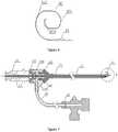
- FIG. 2is a schematic plan view of the pericardium puncture needle assembly 10 according to one exemplary embodiment of the present invention
- FIG. 3is the sectional view of the pericardium puncture needle assembly 10 according to one exemplary embodiment of the present invention, which illustrates the connecting relationships of the connector 11, the puncture needle 12, and the guide wire 13
- FIG. 4is the cross sectional view taken along line B-B indicated in FIG. 2 .
- the puncture needle 12has a tubular construction with a distal end and a proximal end, and may be made from any suitable biocompatible materials, such as stainless steel or nickel titanium alloy.
- the distal end of needle 12may has a structure without or with a needlepoint.
- the puncture needle 12may be formed by a single tube, or can be joined by two sections of tubes. While the puncture needle 12 is joined by two sections of tubes, it may include a distal end tube 21 and a proximal end tube 22, as shown in FIG.3 .
- One means for connecting the distal end tube 21 and proximal end tube 22is to insert one end of the distal end tube 21 into the proximal end tube 22, and fix them by bonding or welding.
- the distal end tube 21 and proximal end tube 22may be made from the same materials, or different materials.
- the distal end tube 21is made from nickel titanium alloy
- the proximal end tube 22is made from stainless steel, a matter which insures that the puncture needle 12 has a certain degree of curvature while in human body.
- the diameter of puncture needle 12may be set according to actual need of applications by those skilled in the art.
- the puncture needle 12may has a tubular structure with a constant diameter, or with different diameters at the distal end and the proximal end. While the puncture needle 12 has a constant diameter, the diameter may be 0.5-1.0mm. While the puncture needle 12 has different diameters at the distal end and proximal end, preferably, the diameter of the distal end is smaller than the diameter of proximal end, because the puncture needle 12 needs to provide some supporting force at the proximal end, while the distal end of the puncture needle 12 needs to be flexible in order to bend. In one exemplary embodiment of the present invention, the inner diameter of the proximal end of the puncture needle 12 is 0.5-2.5mm, and the inner diameter of the distal end is 0.2-1.5mm.
- the length of the puncture needle 12may be set according to actual need of applications by those skilled in the art.
- the length of the distal end tube 21may be 40-100mm
- the length of the proximal end tube 22may be 60-120mm.
- the length of the connecting partmay be set according to actual need of applications by those skilled in the art.
- FIG. 5shows an enlarged view of part C of FIG. 1 , illustrating the structure of the curved distal section of the guide wire 13 of the pericardium puncture needle assembly according to one exemplary embodiment of the present invention
- FIG. 6shows the structure of the curved distal section of the guide wire 13 of the pericardium puncture needle assembly according to another exemplary embodiment of the present invention.
- the guide wire 13has an elongated and bendable flexible construction, which may be made from any suitable highly elastic materials, such as nickel titanium alloys.
- the guide wire 13comprises a curved distal section 32 and a straight proximal section, and the curved distal section 32 is formed by bending the guide wire.
- the curved distal section 32has such a structure that is adapted to regain its preset curved shape from straightened state. Because the guide wire is made from highly elastic material, the curved distal section 32 is in a straightened state when it is placed within the puncture needle 12, and regains its preset curved shape when it passes through the puncture needle 12.
- the curved distal section 32 and the guide wire 13may be formed integrately, or formed separately.
- the guide wire 13may be a solid structure without cavity inside, or may be any other suitable structures.
- the tip end of the curved distal section 32has a sharp tip structure, which is used for piercing pericardium without inducing any hurt.
- the sharp tipbends at least 90 degrees within a length range of no more than 3mm starting from the sharp tip of the curved distal section of the guide wire.
- the sharp tipbends at least 90 degrees within a length range of no more than 1-2mm starting from the sharp tip of the curved distal section of the guide wire.
- the sharp tip structurecomprises a curved section 323 which has a curvature radius of no more than 2mm.
- the curved shape of the curved distal section 32 starting from the proximal end of the sharp tip structuremay be helix curve, involute curve, or other suitable irregular curves, such as combination of arcs and straight line, combination of involute curve and straight line, or any other appropriate curved shapes.
- the curved shape, starting from the proximal end of the sharp tip structure, of the curved distal section 32is helix curve or involute curve, its curvature radius may increase gradually or stepwise.
- the curvature radiusmay change irregularly, e.g. increasing gradually or stepwise, but decreasing along with the further bending of the guide wire, and then increasing again gradually or stepwise.
- the sharp tipmay be encircled by the curved shape of the curved distal section, and is less likely to hurt the pericardium during piercing. Even if the sharp tip is not encircled by the curved shape of the curved distal section, the force of the guide wire is not able to be delivered to the sharp tip because the guide wire is very long and flexible. Therefore, it is not likely to hurt the heart.
- the curved shape of the curved distal section 32 starting from the proximal end of the sharp tip structureis a combination of involute curve and straight line.
- the curved shape of the curved distal section 32 starting from the proximal end of the sharp tip structureis a combination of helix curve and straight line.
- the curved distal section 32comprises at least one curved section, which may be one curved section, two curved sections, three curved sections or more curved sections. As shown in FIG. 5 and FIG.
- the curved shape, starting from the proximal end of the sharp tip structure, of the curved distal section 32includes a first curved section 321 and a second curved section 322.
- the part of guide wire between the first curved section 321 and the second curved section 322, and the part of guide wire between the second curved section 322 and the curved section 323 of the sharp tip structureextend along a direction parallel to the puncture needle 12.
- the part of guide wire between the first curved section 321 and the second curved section 322, and the part of guide wire between the second curved section 322 and the curved section 323 of the sharp tip structuremay be in the form of straight line.
- the curvature radius of the first curved section 321 and the second curved section 322may be set according to actual need of applications by those skilled in the art.
- the curvature radius of the first curved section 321is not greater than 1.5mm
- the curvature radius of the second curved section 323is not greater than 2mm.
- the part of the curved distal section 32 extending from the proximal end of the sharp tip structure to the proximal end of the guide wiremay be cylindrical, the diameter of which may be set according to actual need of applications by those skilled in the art. For example, the diameter is 0.2-1mm in one preferred embodiment of the present invention.
- the part of the curved distal section 32 extending from the proximal end of the sharp tip structure to the proximal end of the guide wiremay also be a flat sheet shape, which has a width of 0.2-1mm as shown in FIG. 5 .
- the width of the flat sheet shape structuremeans the width indicated by symbol 324 in FIG. 5 .
- a sheathmay be disposed within the puncture needle 12 as shown in FIG. 1, FIG.
- the sheathextends within the puncture needle 12.
- the proximal end of the sheathis fixed to the connector 11.
- the distal end of the sheathmay be a free end, or may also be fixed to the distal end of the puncture needle 12.
- the distal end of the guide wire 13enters the puncture needle 12 through the sheath, and extends within the puncture needle 12 along its axial direction.
- the proximal end of guide wire 13may be fixed to the connector 11 depending on actual needs, or may be a free end without being fixed. It is possible that there is no sheath within the puncture needle 12.
- the guide wire 13is pushed through the puncture needle 12 by a guide wire pusher when the puncture needle is used.
- the guide wire pusheralso works as a sheath.
- the connector 11which is fixed to the proximal end of the puncture needle 12, may be a luer connector. Once completing piercing and drawing out the guide wire 13, the connector may be used for injecting drugs or other liquids, or extracting effusion from the body.
- the curved distal section 32is in straightened state while it is wholly within the puncture needle 12.
- the sharp tip of the curved distal section 32pierces the pericardium, and the guide wire 13 gradually enters the pericardium.
- the curved distal section 32gradually becomes curved until regaining its preset shape.
- the puncture needle 12enters into the pericardium, and the piercing procedure is finished.
- the guide wire 13is drawn out of human body. During the drawing out of the guide wire 13, it gradually regains straightened state from curved state, and is withdrawn into the puncture needle 12. After the guide wire 13 is drawn out of the body, it is possible to inject drugs or contrast agents, or extract pericardial effusion through the connector 11.
- FIG. 7is a perspective structural view of the pericardium puncture needle assembly 10 according to another exemplary embodiment of the present invention.
- FIG. 8is the enlarged view of the part indicated by symbol D of FIG. 7 .
- the pericardium puncture needle assembly 10comprises puncture needle 12, and the guide wire 13 extends within the needle 12.
- the guide wire 13is a bendable, elongated flexible construction including a distal end and a proximal end.
- the guide wire 13includes a curved distal section 32 and a straight proximal section.
- the curved distal sectioncomprises a sharp tip structure at its distal end.
- a negative pressure deviceis fixed to the proximal end of the puncture needle 12.
- the distal end of the puncture needlecomprises a lateral abutment area in order to form certain suction area between the distal end of the puncture needle and the pericardial tissue, thus producing negative pressure.
- the guide wire 13is made from highly elastic material.
- the curved distal section 32is formed by bending the guide wire, and has such a structure that is adapted to regain its preset curved shape from straightened state.
- the sharp tipbends at least 90 degrees within a length range of no more than 3mm starting from the sharp tip of the curved distal section of the guide wire.
- the curved distal section 32may be in any other suitable curved shape.
- the sharp tip structurecomprises a curved section with a curvature radius of not greater than 2mm.
- the curved distal section 32starting from the proximal end of the sharp tip structure, may be involute curve, e.g. square involute, triangle involute, or any other involutes, the curvature radius of which increases continuously or stepwise, as shown in FIG. 7 and FIG. 8 .
- the negative pressure devicecomprises a junction valve 14 and a negative pressure tee valve 15.
- the junction valve 14 and negative pressure tee valve 15are connected by a negative pressure tube 16.
- the junction valve 14may be formed integrately, or formed in separate parts.
- the junction valve 14comprises a valve body 141.
- the valve body 141includes a distal end, a proximal end and a central cavity.
- a lower end cap 142is disposed at the distal end of the valve body 141, and an upper end cover 143 is disposed at the proximal end of the valve body 141.
- the proximal end of the puncture needle 12is fixed inside the lower end cap 142, and a protective sheath may be disposed at the proximal end.
- a gasket 144is disposed within the upper end cap 143 for sealing purpose.
- One end of the negative pressure connecting tube 16is fixed to the junction valve 14, and the other end is fixed to the negative pressure tee valve 15.
- a sheath 17is disposed within the puncture needle 12.
- the sheath 17extends within the puncture needle 12, and the proximal end of sheath 17 extends out of the junction valve 14.
- the guide wire 13extends through the sheath 17 into the puncture needle 12, and extends within the puncture needle 12.
- a connector 11is disposed at the proximal end of the junction valve 14, which may be a luer connector. After finishing piercing and drawing out the guide wire 13, the connector may be used for injecting drugs or other liquids into the body, or extracting pericardial effusion from the body.
- the other structures of the guide wire 13 and puncture needle 12are identical to those in the embodiments illustrated in FIG 1 to FIG. 5 .
- FIG. 9is a structural perspective view of the curved distal section 32 according to another embodiment of the present invention.
- the guide wire 13is an elongated and bendable flexible structure, which includes a curved distal section 32 and a straight proximal section.
- the guide wireis made from highly elastic material.
- the curved distal section 32is formed by bending the guide wire 13, and comprises a sharp tip structure at its distal end.
- the curved distal section 32has such a structure that is adapted to regain its preset curved shape from straightened state.
- the sharp tipbends at least 90 degrees within a length range of no more than 3mm starting from the sharp tip of the curved distal section of the guide wire.
- the sharp tip structurecomprises a curved section, which has a curvature radius of not greater than 2mm.
- the curved shape of the curved distal section of the guide wire starting from the proximal end of the sharp tip structuremay be helix curve, which has a curvature radius increasing continuously, as shown in FIG. 9 .
- the curved distal section 32may be in form of other suitable curved shape.
- FIG. 10is a structural perspective view of the curved distal section 32 according to another embodiment of the present invention.
- the guide wire13is an elongated and bendable flexible structure, which includes a curved distal section 32 and a straight proximal section.
- the guide wireis made from highly elastic material.
- the curved distal section 32is formed by bending the guide wire 13, and includes a sharp tip structure at its distal end.
- the curved distal section 32is such a structure that it is adapted to regain its preset shape from straightened state.
- the sharp tipbends at least 90 degrees within a length range of no more than 3mm starting from the sharp tip of the distal end of the guide wire.
- the sharp tip structurecomprises a curved section, which has a curvature radius of not greater than 2mm.
- the curved distal section 32starting from the proximal end of the sharp tip structure, may be irregular curve, which has a curvature radius changing irregularly, as shown in FIG. 10 .
- the curvature radiusmay increase gradually or stepwise, but decrease along with the further bending of the guide wire, and then increase again gradually or stepwise, or it may repeatedly change as above.
- the curved distal section 32may be in form of other suitable curved shape.
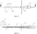
- FIG. 11is a structural perspective view of the pericardium puncture needle assembly 10 according to another preferable embodiment of the present invention.
- FIG. 12is the cross sectional view taken as indicated by arrows E-E of FIG. 11 .
- the pericardium puncture needle assembly 10comprises a puncture needle 12, and a guide wire 13 extends within the puncture needle 12.
- the guide wire13is an elongated and bendable flexible structure, which includes a curved distal section 32 and a straight proximal section.
- the guide wireis made from highly elastic material.
- the curved distal section 32is formed by bending the guide wire 13, which includes a sharp tip structure at its distal end.
- the curved distal section 32is adapted to regain its preset curved shape from straightened state.
- the sharp tipbends at least 90 degrees within a length range of no more than 3mm starting from the sharp tip of the distal end of the guide wire.
- the sharp tip structurecomprises a curved section, which has a curvature radius of not greater than 2mm.
- a connector 11is fixed to the proximal end of the puncture needle 12.
- the curved distal section 32may be helix curve, which has a curvature radius increasing continuously, as shown in FIG. 11 and FIG. 12 .
- the curved distal section 32may be in form of other suitable curved shape.
- the distal end of the outer sheath 18is a spherical structure 81, or may be other suitable shape.
- the spherical structure 81 and the outer sheath 18may be formed separately or integrately.
- the outer sheath 18may be made from any suitable biocompatible materials, e.g. stainless steel. When the spherical structure 81 is formed separately to the outer sheath 18, they may be made from the same material, or from different materials.
- the proximal end of the outer sheath 18is fixed to a connector 19 by bonding or other suitable methods.
- the connector 19may be any suitable configuration, e.g. luer connector.
- the connector 11may slide freely at the proximal end of the connector 19, or be fixed through self-locking. After entering into thoracic cavity, the distal end of the puncture needle 12 may be withdrawn into the outer sheath 18 by controlling the connector 11. Therefore, while the outer sheath 18 is pushed forward, it is less likely to hurt the tissue.
- the distal end of the puncture needle 12may be used to abut on the pericardium, or alternatively, the puncture needle 12 may be withdrawn and the spherical structure 81 of the distal end of the outer sheath may be directly used to abut on the pericardium,, so as to complete the puncture procedure.
Landscapes
- Health & Medical Sciences (AREA)
- Life Sciences & Earth Sciences (AREA)
- Surgery (AREA)
- Heart & Thoracic Surgery (AREA)
- General Health & Medical Sciences (AREA)
- Engineering & Computer Science (AREA)
- Veterinary Medicine (AREA)
- Biomedical Technology (AREA)
- Public Health (AREA)
- Animal Behavior & Ethology (AREA)
- Medical Informatics (AREA)
- Nuclear Medicine, Radiotherapy & Molecular Imaging (AREA)
- Molecular Biology (AREA)
- Pathology (AREA)
- Hematology (AREA)
- Anesthesiology (AREA)
- Vascular Medicine (AREA)
- Biophysics (AREA)
- Pulmonology (AREA)
- Surgical Instruments (AREA)
- Prostheses (AREA)
- Infusion, Injection, And Reservoir Apparatuses (AREA)
Description
- This application claims the priority of Chinese application
CN201110139534.9 filed on May 27, 2011 - The present invention relates to a puncture needle assembly, and more particularly, it relates to a pericardium puncture needle assembly.
- Pericardium is a layer of connective tissue membrane that tightly wraps around the heart. In epicardial ablation, it is necessary to manually open a path through the pericardium tightly around the heart, in order to let the ablation catheter to access the space between the pericardium and the outwall of heart to conduct ablation.
WO 2009/112062 A1 refers to device for a medical procedure within the vasculature of a patient, comprising puncturing means provided at a distal end of the device for puncturing tissue in a supported state, and an elongate member having a proximal end, a distal end provided with a puncturing means and a flexible length there between, wherein the elongate member is arranged to be advanced through the vasculature in an unsupported state of the puncturing means without damaging the walls of the vasculature.CN 201 404 278 Y refers to to a sleeve type puncture needle. The sleeve type puncture needle comprises a puncture needle, a sleeve and a suction pipe as well as a discharge pipe and a syringe which are connected with the suction pipe, wherein, the puncture needle is arranged in the sleeve, the suction pipe is communicated with an inner cavity of the sleeve, the discharge pipe is communicated with a liquid storage bag, the sleeve comprises a front hose and a rear buffer chamber, the front hose is communicated with the rear buffer chamber, the front hose is a memory curled hose, a plurality of suction holes are formed on the outer surface of the front section of the front hose, a sealing component is arranged at the tail part of the rear buffer chamber, a connector of the suction pipe is arranged on the side surface of the front end of the rear buffer chamber, the suction pipe is communicated with the inner cavity of the rear buffer chamber through the connector of the suction pipe, a three-way valve is connected at the back end of the suction pipe, the connector of the syringe is communicated with the other interface of the three-way valve, and the third interface of the three-way valve is communicated with the discharge pipe.US 4991578 A refers to method and system for positioning a defibrillation electrode within the pericardial space of a mammal is disclosed which includes means for distending the pericardium from the heart by injecting a small volume of fluid into the pericardium. A needle having a lumen therethrough is inserted from a sub-xiphoid or other percutaneous position into the body tissue until a tip thereof punctures the distended pericardium at a selected location. A guide wire is inserted into the pericardium through the lumen of the needle, and while the guide wire remains in the pericardial space, the needle is removed. A sheath is introduced over the guide wire, with the aid of a dilator, and inserted into the tissue until one end thereof is positioned within the pericardium. The defibrillation lead, with its electrode in a retracted position, is inserted through the sheath until the electrode is likewise positioned within the pericardium, whereupon the electrode is deployed in order to make contact with a large area of tissue within the pericardium. Additional leads and electrodes may be introduced and deployed in a like manner.US 2009/105654 A1 refers to a transseptal guidewire and methods for perforating the intra-atrial septum of the heart are disclosed. The transseptal guidewire has an elongated body, an end section biased in a curved configuration to define a proximal curve, and a distal section biased in a curved configuration to define a distal curve, the distal curve being oriented in a direction generally opposite that of the proximal curve.WO 2007/006055 A2 refers to an intravenous catheter insertion device and method of use are described. The insertion device coordinates movement of an access needle, a coaxial intravenous catheter and a flexible safety guidewire. A vein is punctured with the access needle, then an actuation member on the insertion device is used to advance the safety guidewire into the vein. The safety guidewire allows the access needle and the intravenous catheter to be safely advanced into the vein. Then, the actuation member is activated to simultaneously withdraw the access needle and the safety guidewire, leaving only the intravenous catheter in the vein. The intravenous catheter is then disconnected from the insertion device and connected to a source of intravenous fluid, medication.- There are a great diversity of pericardium puncture equipments on market. For example, Chinese patent
CN00257117.X disclosed a type of noninvasive pericardium puncture needle, which comprises an outer sheath, an inner needle, and an end cap. The outer sheath is a flexible hollow tube that accommodates the inner needle. The inner needle is a solid puncture needle, which is fixed to the distal end of the outer sheath by the end cap. Once the pericardium is pierced by the needle, the needle is then withdrawn. The outer sheath continues advancing into the pericardium, so that the pericardial effusion can be extracted or drugs can be injected. - However, most of existing puncture needles are straight needle structure. In clinical operations, such a structure often pierces insufficiently and leads to puncture failure, or sometimes it tends to over-pierce and hurts the heart.
- Claim 1 defines the invention and the dependent claims disclose preferred embodiments. The present invention provides a pericardium puncture needle assembly, comprising a guide wire and a puncture needle, wherein the guide wire extends within the puncture needle, the puncture needle extending along a longitudinal axis, the guide wire has a curved distal section and a straight proximal section, the curved distal section is formed by bending the guide wire, the tip end of the curved distal section is a sharp tip structure, the guide wire is made from highly elastic material and is configured to adopt a straightened state within the puncture needle and regain its preset curved shape when it passes out of the puncture needle, characterized in that, the sharp tip is used for piercing pericardium, and bends at least 90 degrees within a length range of no more than 3mm starting from the sharp tip of the curved distal section of the guide wire in the preset curved shape, and the longitudinal axis of the puncture needle, the preset curved shape of the curved distal section, and the sharp tip all are within the same plane.
- Preferably, the sharp tip bends at least 90 degrees within a length range of 1-2mm starting from the sharp tip of the curved distal section of the guide wire.
- Preferably, within a length range of no more than 3mm starting from the sharp tip, the sharp tip structure comprises a curved section, which has a curvature radius of less than 2mm.
- After the sharp tip bends 90 degrees, a curved shape, starting from the proximal end of the sharp tip structure, of the curved distal section is involute curve, helix curve, or irregular curve.
- In one exemplary embodiment, after the sharp tip bends 90 degrees, the curved shape, starting from the proximal end of the sharp tip structure, of the curved distal section is involute curve or helix curve with a curvature radius increasing gradually or stepwise.
- In one exemplary embodiment, after the sharp tip bends 90 degrees, the curved shape, starting from the proximal end of the sharp tip structure, of the curved distal section is irregular curved shape including at least one curved section.
- Preferably, the curved shape, starting from the proximal end of the sharp tip structure, of the curved distal section includes a first curved section and a second curved section.
- The curvature radius of the first curved section is not greater than 1.5mm, and the curvature radius of the second curved section is not greater than 2mm.
- In one preferable embodiment, a part of the curved distal end extending from the proximal end of the sharp tip structure to the proximal end of the guide wire is in cylindrical shape, which has a diameter of 0.2-1mm.
- In another preferable embodiment, a part of the curved distal section extending from the proximal end of the sharp tip structure to the proximal end of the guide wire is in flat sheet shape, which has a width of 0.2-1mm.
- In one preferable embodiment, the puncture needle is formed by connecting two tubes, one is the distal end tube and the other is the proximal end tube, the distal end tube has a length of 40-100mm, and the proximal end tube has a length of 60-120mm.
- The diameter of distal end of the puncture needle is smaller than the diameter of its proximal end.
- The inner diameter of the proximal end of the puncture needle is 0.5-2.5mm, and the inner diameter of its distal end is 0.2-1.5mm.
- Preferably, an outer sheath is nested around the puncture needle, and the distal end of the outer sheath is in a spherical structure.
- It is not likely to hurt the heart during pericardium puncture with the pericardium puncture needle assembly in preferable embodiments of the invention.
FIG. 1 is a structural perspective view of the pericardium puncture needle assembly according to one exemplary embodiment of the present invention;FIG. 2 is a plan view of the pericardium puncture needle assembly according to one exemplary embodiment of the present invention;FIG. 3 is a sectional view taken along line B-B as shown inFIG. 2 , which illustrates the inner structure of the pericardium puncture needle assembly according to one exemplary embodiment of the present invention;FIG. 4 is a sectional view taken along line A-A shown inFIG. 2 , which illustrates the sectional structure of the pericardium puncture needle assembly according to one exemplary embodiment of the present invention;FIG. 5 is the enlarged view of part C ofFIG. 1 , which illustrates the structure of the curved distal section according to one exemplary embodiment of the present invention;FIG. 6 illustrates the structure of the curved distal section of theguide wire 13 according to another exemplary embodiment of the present invention;FIG. 7 is a structural perspective view of the pericardiumpuncture needle assembly 10 according to another exemplary embodiment of the present invention;FIG. 8 is the enlarged view of the part D ofFIG. 7 ;FIG. 9 is a structural perspective view of the curveddistal section 32 according to another exemplary embodiment of the present invention;FIG. 10 is a structural perspective view of the curveddistal section 32 according to another exemplary embodiment of the present invention;FIG. 11 is a structural perspective view of the pericardiumpuncture needle assembly 10 according to another exemplary embodiment of the present invention;FIG. 12 is a sectional view taken along line E-E ofFIG. 11 .- This invention will now be described and explained in detail through embodiments and in combination with the drawings. However, this invention is not limited to the following embodiments.
FIG. 1 is a perspective view of the pericardiumpuncture needle assembly 10 according to one exemplary embodiment of the present invention, which comprises aneedle 12 and aguide wire 13 extending within theneedle 12. Theguide wire 13 has an elongated, bendable flexible construction, which comprises a curved distal section and a straight proximal section. The curved distal section ofguide wire 13 is formed by bending the guide wire, and its tip end is a sharp tip structure. Theguide wire 13 is made from highly elastic material. The curved distal section is adapted to regain its preset curved shape from straightened state. The sharp tip, within a length range of no more than 3mm starting from the sharp tip of the curved distal section of the guide wire, bends at least 90 degrees. Once the pericardium is pierced by the sharp tip of the guide wire, the angle between the pointing direction of the sharp tip and the advancing direction of guide wire is bigger than 90 degrees. Therefore, it is less likely to hurt the pericardium. The sharp tip structure of this invention means such a part of the guide wire that is within a length range of no more than 3mm starting from the sharp tip and in which the sharp tip bends through 90 degrees. The curvature radius of the surface of the sharp tip is not greater than 0.1mm. The sharp tip structure comprises a distal end and a proximal end. The sharp tip mentioned above means the distal end of the sharp tip structure, and the sharp tip is extremely sharp and may be a spherical structure at the micro level. Aconnector 11 is fixed at the proximal end of thepuncture needle 12.FIG. 2 is a schematic plan view of the pericardiumpuncture needle assembly 10 according to one exemplary embodiment of the present invention;FIG. 3 is the sectional view of the pericardiumpuncture needle assembly 10 according to one exemplary embodiment of the present invention, which illustrates the connecting relationships of theconnector 11, thepuncture needle 12, and theguide wire 13; andFIG. 4 is the cross sectional view taken along line B-B indicated inFIG. 2 . Thepuncture needle 12 has a tubular construction with a distal end and a proximal end, and may be made from any suitable biocompatible materials, such as stainless steel or nickel titanium alloy. The distal end ofneedle 12 may has a structure without or with a needlepoint.- The
puncture needle 12 may be formed by a single tube, or can be joined by two sections of tubes. While thepuncture needle 12 is joined by two sections of tubes, it may include adistal end tube 21 and aproximal end tube 22, as shown inFIG.3 . One means for connecting thedistal end tube 21 andproximal end tube 22 is to insert one end of thedistal end tube 21 into theproximal end tube 22, and fix them by bonding or welding. Thedistal end tube 21 andproximal end tube 22 may be made from the same materials, or different materials. For example, thedistal end tube 21 is made from nickel titanium alloy, while theproximal end tube 22 is made from stainless steel, a matter which insures that thepuncture needle 12 has a certain degree of curvature while in human body. - The diameter of
puncture needle 12 may be set according to actual need of applications by those skilled in the art. Thepuncture needle 12 may has a tubular structure with a constant diameter, or with different diameters at the distal end and the proximal end. While thepuncture needle 12 has a constant diameter, the diameter may be 0.5-1.0mm. While thepuncture needle 12 has different diameters at the distal end and proximal end, preferably, the diameter of the distal end is smaller than the diameter of proximal end, because thepuncture needle 12 needs to provide some supporting force at the proximal end, while the distal end of thepuncture needle 12 needs to be flexible in order to bend. In one exemplary embodiment of the present invention, the inner diameter of the proximal end of thepuncture needle 12 is 0.5-2.5mm, and the inner diameter of the distal end is 0.2-1.5mm. - The length of the
puncture needle 12 may be set according to actual need of applications by those skilled in the art. In one exemplary embodiment of the present invention, when thepuncture needle 12 is made by connecting thedistal end tube 21 andproximal end tube 22, the length of thedistal end tube 21 may be 40-100mm, and the length of theproximal end tube 22 may be 60-120mm. The length of the connecting part may be set according to actual need of applications by those skilled in the art. FIG. 5 shows an enlarged view of part C ofFIG. 1 , illustrating the structure of the curved distal section of theguide wire 13 of the pericardium puncture needle assembly according to one exemplary embodiment of the present invention, andFIG. 6 shows the structure of the curved distal section of theguide wire 13 of the pericardium puncture needle assembly according to another exemplary embodiment of the present invention. As shown inFIG. 3, FIG. 5 , andFIG. 6 , theguide wire 13 has an elongated and bendable flexible construction, which may be made from any suitable highly elastic materials, such as nickel titanium alloys. Theguide wire 13 comprises a curveddistal section 32 and a straight proximal section, and the curveddistal section 32 is formed by bending the guide wire. The curveddistal section 32 has such a structure that is adapted to regain its preset curved shape from straightened state. Because the guide wire is made from highly elastic material, the curveddistal section 32 is in a straightened state when it is placed within thepuncture needle 12, and regains its preset curved shape when it passes through thepuncture needle 12. The curveddistal section 32 and theguide wire 13 may be formed integrately, or formed separately. Theguide wire 13 may be a solid structure without cavity inside, or may be any other suitable structures.- As shown in
FIG. 3, FIG. 5 , andFIG. 6 , the tip end of the curveddistal section 32 has a sharp tip structure, which is used for piercing pericardium without inducing any hurt. The sharp tip bends at least 90 degrees within a length range of no more than 3mm starting from the sharp tip of the curved distal section of the guide wire. Preferably, the sharp tip bends at least 90 degrees within a length range of no more than 1-2mm starting from the sharp tip of the curved distal section of the guide wire. Within a length range of no more than 3mm starting from the sharp tip of the curved distal section of the guide wire, the sharp tip structure comprises acurved section 323 which has a curvature radius of no more than 2mm. - As shown in
FIG. 3, FIG. 5 , andFIG. 6 , after the sharp tip bends 90 degrees, the curved shape of the curveddistal section 32 starting from the proximal end of the sharp tip structure may be helix curve, involute curve, or other suitable irregular curves, such as combination of arcs and straight line, combination of involute curve and straight line, or any other appropriate curved shapes. When the curved shape, starting from the proximal end of the sharp tip structure, of the curveddistal section 32 is helix curve or involute curve, its curvature radius may increase gradually or stepwise. When the curved shape, starting from the proximal end of the sharp tip structure, of the curveddistal section 32 is irregular curve, such as combination of arcs and straight line, combination of involute curve and straight line, or any other appropriate curved shapes, its curvature radius may change irregularly, e.g. increasing gradually or stepwise, but decreasing along with the further bending of the guide wire, and then increasing again gradually or stepwise. After the pericardium is pierced by the sharp tip of the curveddistal section 32, the angle between the advancing direction of the guide wire and the pointing direction of the sharp tip is bigger than 90 degrees, thus avoiding piercing the heart. Even if the angle between the advancing direction of the guide wire and the pointing direction of the sharp tip is less than 90 degrees when the curveddistal section 32 enters the pericardium gradually, it is not likely to hurt the heart, because the guide wire is very long and flexible, and thus the force of the guide wire is not able to be delivered to the sharp tip. Besides, the sharp tip may be encircled by the curved shape of the curved distal section, and is less likely to hurt the pericardium during piercing. Even if the sharp tip is not encircled by the curved shape of the curved distal section, the force of the guide wire is not able to be delivered to the sharp tip because the guide wire is very long and flexible. Therefore, it is not likely to hurt the heart. - As shown in
Fig 5 , in this embodiment, after the sharp tip bends 90 degrees, the curved shape of the curveddistal section 32 starting from the proximal end of the sharp tip structure is a combination of involute curve and straight line. As shown inFIG. 6 , in this embodiment, after the sharp tip bends 90 degrees, the curved shape of the curveddistal section 32 starting from the proximal end of the sharp tip structure is a combination of helix curve and straight line. The curveddistal section 32 comprises at least one curved section, which may be one curved section, two curved sections, three curved sections or more curved sections. As shown inFIG. 5 andFIG. 6 , the curved shape, starting from the proximal end of the sharp tip structure, of the curveddistal section 32 includes a firstcurved section 321 and a secondcurved section 322. Preferably, the part of guide wire between the firstcurved section 321 and the secondcurved section 322, and the part of guide wire between the secondcurved section 322 and thecurved section 323 of the sharp tip structure extend along a direction parallel to thepuncture needle 12. The part of guide wire between the firstcurved section 321 and the secondcurved section 322, and the part of guide wire between the secondcurved section 322 and thecurved section 323 of the sharp tip structure may be in the form of straight line. - The curvature radius of the first
curved section 321 and the secondcurved section 322 may be set according to actual need of applications by those skilled in the art. For example, in one exemplary embodiment of the present invention, the curvature radius of the firstcurved section 321 is not greater than 1.5mm, and the curvature radius of the secondcurved section 323 is not greater than 2mm. - The part of the curved
distal section 32 extending from the proximal end of the sharp tip structure to the proximal end of the guide wire may be cylindrical, the diameter of which may be set according to actual need of applications by those skilled in the art. For example, the diameter is 0.2-1mm in one preferred embodiment of the present invention. The part of the curveddistal section 32 extending from the proximal end of the sharp tip structure to the proximal end of the guide wire may also be a flat sheet shape, which has a width of 0.2-1mm as shown inFIG. 5 . The width of the flat sheet shape structure means the width indicated bysymbol 324 inFIG. 5 . A sheath, not shown in figures, may be disposed within thepuncture needle 12 as shown inFIG. 1, FIG. 2 , andFIG. 3 . The sheath extends within thepuncture needle 12. The proximal end of the sheath is fixed to theconnector 11. The distal end of the sheath may be a free end, or may also be fixed to the distal end of thepuncture needle 12. The distal end of theguide wire 13 enters thepuncture needle 12 through the sheath, and extends within thepuncture needle 12 along its axial direction. The proximal end ofguide wire 13 may be fixed to theconnector 11 depending on actual needs, or may be a free end without being fixed. It is possible that there is no sheath within thepuncture needle 12. Theguide wire 13 is pushed through thepuncture needle 12 by a guide wire pusher when the puncture needle is used. The guide wire pusher also works as a sheath. - The
connector 11, which is fixed to the proximal end of thepuncture needle 12, may be a luer connector. Once completing piercing and drawing out theguide wire 13, the connector may be used for injecting drugs or other liquids, or extracting effusion from the body. - According to one preferable embodiment of the present invention, during the use of pericardium puncture needle assembly, the curved
distal section 32 is in straightened state while it is wholly within thepuncture needle 12. When pushing forward theguide wire 13, the sharp tip of the curveddistal section 32 pierces the pericardium, and theguide wire 13 gradually enters the pericardium. The curveddistal section 32 gradually becomes curved until regaining its preset shape. Thepuncture needle 12 enters into the pericardium, and the piercing procedure is finished. Then theguide wire 13 is drawn out of human body. During the drawing out of theguide wire 13, it gradually regains straightened state from curved state, and is withdrawn into thepuncture needle 12. After theguide wire 13 is drawn out of the body, it is possible to inject drugs or contrast agents, or extract pericardial effusion through theconnector 11. FIG. 7 is a perspective structural view of the pericardiumpuncture needle assembly 10 according to another exemplary embodiment of the present invention.FIG. 8 is the enlarged view of the part indicated by symbol D ofFIG. 7 . As shown inFIG. 7 andFIG. 8 , the pericardiumpuncture needle assembly 10 comprisespuncture needle 12, and theguide wire 13 extends within theneedle 12. Theguide wire 13 is a bendable, elongated flexible construction including a distal end and a proximal end. Theguide wire 13 includes a curveddistal section 32 and a straight proximal section. The curved distal section comprises a sharp tip structure at its distal end. A negative pressure device is fixed to the proximal end of thepuncture needle 12. The distal end of the puncture needle comprises a lateral abutment area in order to form certain suction area between the distal end of the puncture needle and the pericardial tissue, thus producing negative pressure.- The
guide wire 13 is made from highly elastic material. The curveddistal section 32 is formed by bending the guide wire, and has such a structure that is adapted to regain its preset curved shape from straightened state. The sharp tip bends at least 90 degrees within a length range of no more than 3mm starting from the sharp tip of the curved distal section of the guide wire. The curveddistal section 32 may be in any other suitable curved shape. Within a length range of no more than 3mm starting from the sharp tip, the sharp tip structure comprises a curved section with a curvature radius of not greater than 2mm. When the sharp tip bends 90 degrees, the curveddistal section 32, starting from the proximal end of the sharp tip structure, may be involute curve, e.g. square involute, triangle involute, or any other involutes, the curvature radius of which increases continuously or stepwise, as shown inFIG. 7 andFIG. 8 . - The negative pressure device comprises a
junction valve 14 and a negativepressure tee valve 15. Thejunction valve 14 and negativepressure tee valve 15 are connected by anegative pressure tube 16. Thejunction valve 14 may be formed integrately, or formed in separate parts. As shown inFIG.7 , thejunction valve 14 comprises avalve body 141. Thevalve body 141 includes a distal end, a proximal end and a central cavity. Alower end cap 142 is disposed at the distal end of thevalve body 141, and anupper end cover 143 is disposed at the proximal end of thevalve body 141. The proximal end of thepuncture needle 12 is fixed inside thelower end cap 142, and a protective sheath may be disposed at the proximal end. Agasket 144 is disposed within theupper end cap 143 for sealing purpose. One end of the negativepressure connecting tube 16 is fixed to thejunction valve 14, and the other end is fixed to the negativepressure tee valve 15. - Preferably, a
sheath 17 is disposed within thepuncture needle 12. Thesheath 17 extends within thepuncture needle 12, and the proximal end ofsheath 17 extends out of thejunction valve 14. Theguide wire 13 extends through thesheath 17 into thepuncture needle 12, and extends within thepuncture needle 12. - A
connector 11 is disposed at the proximal end of thejunction valve 14, which may be a luer connector. After finishing piercing and drawing out theguide wire 13, the connector may be used for injecting drugs or other liquids into the body, or extracting pericardial effusion from the body. In the embodiment shown inFIG. 7 andFIG. 8 , the other structures of theguide wire 13 and punctureneedle 12 are identical to those in the embodiments illustrated inFIG 1 to FIG. 5 . FIG. 9 is a structural perspective view of the curveddistal section 32 according to another embodiment of the present invention. As shown inFIG. 9 , theguide wire 13 is an elongated and bendable flexible structure, which includes a curveddistal section 32 and a straight proximal section. The guide wire is made from highly elastic material. The curveddistal section 32 is formed by bending theguide wire 13, and comprises a sharp tip structure at its distal end. The curveddistal section 32 has such a structure that is adapted to regain its preset curved shape from straightened state.- The sharp tip bends at least 90 degrees within a length range of no more than 3mm starting from the sharp tip of the curved distal section of the guide wire. Within a length range of no more than 3mm starting from the sharp tip, the sharp tip structure comprises a curved section, which has a curvature radius of not greater than 2mm. After the sharp tip bends 90 degrees, the curved shape of the curved distal section of the guide wire starting from the proximal end of the sharp tip structure may be helix curve, which has a curvature radius increasing continuously, as shown in
FIG. 9 . The curveddistal section 32 may be in form of other suitable curved shape. FIG. 10 is a structural perspective view of the curveddistal section 32 according to another embodiment of the present invention. As shown inFIG. 10 , the guide wire13 is an elongated and bendable flexible structure, which includes a curveddistal section 32 and a straight proximal section. The guide wire is made from highly elastic material. The curveddistal section 32 is formed by bending theguide wire 13, and includes a sharp tip structure at its distal end. The curveddistal section 32 is such a structure that it is adapted to regain its preset shape from straightened state.- The sharp tip bends at least 90 degrees within a length range of no more than 3mm starting from the sharp tip of the distal end of the guide wire. Within a length range of no more than 3mm starting from the sharp tip, the sharp tip structure comprises a curved section, which has a curvature radius of not greater than 2mm. After the sharp tip bends 90 degrees, the curved
distal section 32, starting from the proximal end of the sharp tip structure, may be irregular curve, which has a curvature radius changing irregularly, as shown inFIG. 10 . For example, the curvature radius may increase gradually or stepwise, but decrease along with the further bending of the guide wire, and then increase again gradually or stepwise, or it may repeatedly change as above. The curveddistal section 32 may be in form of other suitable curved shape. FIG. 11 is a structural perspective view of the pericardiumpuncture needle assembly 10 according to another preferable embodiment of the present invention.FIG. 12 is the cross sectional view taken as indicated by arrows E-E ofFIG. 11 . As shown inFIG. 11 and FIG. 12 , the pericardiumpuncture needle assembly 10 comprises apuncture needle 12, and aguide wire 13 extends within thepuncture needle 12. The guide wire13 is an elongated and bendable flexible structure, which includes a curveddistal section 32 and a straight proximal section. The guide wire is made from highly elastic material. The curveddistal section 32 is formed by bending theguide wire 13, which includes a sharp tip structure at its distal end. The curveddistal section 32 is adapted to regain its preset curved shape from straightened state. The sharp tip bends at least 90 degrees within a length range of no more than 3mm starting from the sharp tip of the distal end of the guide wire. Within a length range of no more than 3mm starting from the sharp tip, the sharp tip structure comprises a curved section, which has a curvature radius of not greater than 2mm. Aconnector 11 is fixed to the proximal end of thepuncture needle 12.- After the sharp tip bends 90 degrees, the curved
distal section 32, starting from the proximal end of the sharp tip structure, may be helix curve, which has a curvature radius increasing continuously, as shown inFIG. 11 and FIG. 12 . The curveddistal section 32 may be in form of other suitable curved shape. - An
outer sheath 18, which comprises a distal end and a proximal end, is nested outside thepuncture needle 12. The distal end of theouter sheath 18 is aspherical structure 81, or may be other suitable shape. Thespherical structure 81 and theouter sheath 18 may be formed separately or integrately. Theouter sheath 18 may be made from any suitable biocompatible materials, e.g. stainless steel. When thespherical structure 81 is formed separately to theouter sheath 18, they may be made from the same material, or from different materials. The proximal end of theouter sheath 18 is fixed to aconnector 19 by bonding or other suitable methods. Theconnector 19 may be any suitable configuration, e.g. luer connector. Theconnector 11 may slide freely at the proximal end of theconnector 19, or be fixed through self-locking. After entering into thoracic cavity, the distal end of thepuncture needle 12 may be withdrawn into theouter sheath 18 by controlling theconnector 11. Therefore, while theouter sheath 18 is pushed forward, it is less likely to hurt the tissue. During the pericardium puncture procedure, the distal end of thepuncture needle 12 may be used to abut on the pericardium, or alternatively, thepuncture needle 12 may be withdrawn and thespherical structure 81 of the distal end of the outer sheath may be directly used to abut on the pericardium,, so as to complete the puncture procedure. - The embodiments of present invention are not limited to those embodiments described above. The scope of the invention is solely defined by the claims.
Claims (13)
- A pericardium puncture needle assembly (10), comprising a guide wire (13) and a puncture needle (12), wherein the guide wire (13) extends within the puncture needle (12), the puncture needle extending along a longitudinal axis, the guide wire (13) has a curved distal section (32) and a straight proximal section, the curved distal section (32) is formed by bending the guide wire (13), the tip end of the curved distal section (32) is a sharp tip structure, the guide wire (13) is made from highly elastic material and is configured to adopt a straightened state within the puncture needle and regain its preset curved shape when it passes out of the puncture needle, the sharp tip is used for piercing pericardium, and bends at least 90 degrees within a length range of no more than 3mm starting from the sharp tip of the curved distal section (32) of the guide wire (13) in the preset curved shape, and the longitudinal axis of the puncture needle, the preset curved shape of the curved distal section, and the sharp tip all are within the same plane.
- The pericardium puncture needle assembly (10) of Claim 1,characterized in that the sharp tip bends at least 90 degrees within a length range of 1-2mm starting from the sharp tip of the curved distal section (32) of the guide wire (13).
- The pericardium puncture needle assembly (10) of Claim 1 or 2,characterized in that within a length range of no more than 3mm starting from the sharp tip, the sharp tip structure comprises a curved section, which has a curvature radius of less than 2mm.
- The pericardium puncture needle assembly (10) of Claim 1, 2, or 3,characterized in that after the sharp tip bends 90 degrees, a curved shape, starting from the proximal end of the sharp tip structure, of the curved distal section (32) is involute curve, helix curve, or irregular curve.
- The pericardium puncture needle assembly (10) of Claim 4,characterized in that after the sharp tip bends 90 degrees, the curved shape, starting from the proximal end of the sharp tip structure, of the curved distal section (32) is involute curve or helix curve with a curvature radius increasing gradually or stepwise.
- The pericardium puncture needle assembly (10) of Claim 4,characterized in that after the sharp tip bends 90 degrees, the curved shape, starting from the proximal end of the sharp tip structure, of the curved distal section (32) is irregular curved shape including at least one curved section.
- The pericardium puncture needle assembly (10) of Claim 6,characterized in that the curved shape, starting from the proximal end of the sharp tip structure, of the curved distal section (32) includes a first curved section and a second curved section; preferably, the curvature radius of the first curved section is not greater than 1.5mm, and the curvature radius of the second curved section is not greater than 2mm.
- The pericardium puncture needle assembly (10) of any of the above claims,characterized in that a part of the curved distal section (32) extending from the proximal end of the sharp tip structure to the proximal end of the guide wire (13) is in cylindrical shape, which has a diameter of 0.2-1mm.
- The pericardium puncture needle assembly (10) of any of the above claims,characterized in that a part of the curved distal section (32) extending from the proximal end of the sharp tip structure to the proximal end of the guide wire (13) is in flat sheet shape, which has a width of 0.2-1mm.
- The pericardium puncture needle assembly (10) of any of the above claims,characterized in that the puncture needle (12) is formed by connecting two tubes, one is the distal end tube and the other is the proximal end tube, the distal end tube has a length of 40-100mm, and the proximal end tube has a length of 60-120mm.
- The pericardium puncture needle assembly (10) of Claim 10,characterized in that the diameter of the distal end of the puncture needle (12) is smaller than the diameter of its proximal end; preferably, the inner diameter of the proximal end of the puncture needle (12) is 0.5-2.5mm, and the inner diameter of its distal end is 0.2-1.5mm.
- The pericardium puncture needle assembly (10) of any of the above claims,characterized in that a negative pressure device is fixed at the proximal end of the puncture needle (12).
- The pericardium puncture needle assembly (10) of any of the above claims,characterized in that an outer sheath (18) is nested outside the puncture needle (12), and the distal end of the outer sheath (18) is in a spherical structure.
Applications Claiming Priority (2)
| Application Number | Priority Date | Filing Date | Title |
|---|---|---|---|
| CN2011101395349ACN102793577A (en) | 2011-05-27 | 2011-05-27 | Pericardium puncture needle assembly |
| PCT/CN2012/000728WO2012163083A1 (en) | 2011-05-27 | 2012-05-25 | Pericardiocentesis needle component |
Publications (3)
| Publication Number | Publication Date |
|---|---|
| EP2716242A1 EP2716242A1 (en) | 2014-04-09 |
| EP2716242A4 EP2716242A4 (en) | 2014-10-22 |
| EP2716242B1true EP2716242B1 (en) | 2021-03-31 |
Family
ID=47193054
Family Applications (1)
| Application Number | Title | Priority Date | Filing Date |
|---|---|---|---|
| EP12791952.0AActiveEP2716242B1 (en) | 2011-05-27 | 2012-05-25 | Pericardiocentesis needle component |
Country Status (4)
| Country | Link |
|---|---|
| US (2) | US9717523B2 (en) |
| EP (1) | EP2716242B1 (en) |
| CN (2) | CN102793577A (en) |
| WO (1) | WO2012163083A1 (en) |
Families Citing this family (45)
| Publication number | Priority date | Publication date | Assignee | Title |
|---|---|---|---|---|
| EP1907042B1 (en) | 2005-07-06 | 2009-03-11 | Vascular Pathways Inc. | Intravenous catheter insertion device and method of use |
| EP2150304B1 (en) | 2007-05-07 | 2010-12-01 | Vascular Pathways Inc. | Intravenous catheter insertion and blood sample devices and method of use |
| US9872971B2 (en) | 2010-05-14 | 2018-01-23 | C. R. Bard, Inc. | Guidewire extension system for a catheter placement device |
| US8932258B2 (en) | 2010-05-14 | 2015-01-13 | C. R. Bard, Inc. | Catheter placement device and method |
| US9950139B2 (en) | 2010-05-14 | 2018-04-24 | C. R. Bard, Inc. | Catheter placement device including guidewire and catheter control elements |
| US11925779B2 (en) | 2010-05-14 | 2024-03-12 | C. R. Bard, Inc. | Catheter insertion device including top-mounted advancement components |
| US10384039B2 (en) | 2010-05-14 | 2019-08-20 | C. R. Bard, Inc. | Catheter insertion device including top-mounted advancement components |
| US8690833B2 (en) | 2011-01-31 | 2014-04-08 | Vascular Pathways, Inc. | Intravenous catheter and insertion device with reduced blood spatter |
| ES2835652T3 (en) | 2011-02-25 | 2021-06-22 | Bard Inc C R | Medical component insertion device including a retractable needle |
| USD903101S1 (en) | 2011-05-13 | 2020-11-24 | C. R. Bard, Inc. | Catheter |
| CN103892891B (en)* | 2012-12-28 | 2019-02-26 | 心诺普医疗技术(北京)有限公司 | A kind of paracentesis pericardii needle assemblies |
| CN109009355B (en)* | 2012-12-28 | 2021-07-20 | 心诺普医疗技术(北京)有限公司 | Pericardium puncture needle assembly |
| WO2014120741A1 (en) | 2013-01-30 | 2014-08-07 | Vascular Pathways, Inc. | Systems and methods for venipuncture and catheter placement |
| CN104546074A (en)* | 2013-10-24 | 2015-04-29 | 心诺普医疗技术(北京)有限公司 | Pericardium puncture needle component |
| US10149618B1 (en) | 2014-03-12 | 2018-12-11 | The Board Of Regents Of The University Of Texas System | Subdural electrode localization and visualization using parcellated, manipulable cerebral mesh models |
| CN105342671B (en)* | 2014-08-20 | 2018-01-05 | 祝金明 | Puncture needle component |
| WO2016037127A1 (en) | 2014-09-05 | 2016-03-10 | C.R. Bard, Inc. | Catheter insertion device including retractable needle |
| CN104490480A (en)* | 2015-01-14 | 2015-04-08 | 浙江伽奈维医疗科技有限公司 | Diamond positioning guide wire and positioning pin |
| CN104586502B (en)* | 2015-01-29 | 2017-06-16 | 广州医科大学附属第一医院 | A kind of thecal puncture guide pin |
| USD903100S1 (en) | 2015-05-01 | 2020-11-24 | C. R. Bard, Inc. | Catheter placement device |
| CN113350614A (en) | 2015-05-15 | 2021-09-07 | C·R·巴德股份有限公司 | Catheter placement device including extendable needle safety feature |
| US10493262B2 (en) | 2016-09-12 | 2019-12-03 | C. R. Bard, Inc. | Blood control for a catheter insertion device |
| EP3585471B1 (en) | 2017-03-01 | 2025-01-01 | C. R. Bard, Inc. | Catheter insertion device |
| CN107049442B (en)* | 2017-06-03 | 2023-05-26 | 成都五义医疗科技有限公司 | Puncture needle comprising diameter adaption device and application method thereof |
| CN107049380B (en)* | 2017-06-03 | 2023-05-26 | 成都五义医疗科技有限公司 | Standardized puncture outfit series products and use method thereof |
| EP3579909B1 (en) | 2017-12-05 | 2020-09-09 | Pedersen, Wesley Robert | Transseptal guide wire puncture system |
| ES2980192T3 (en) | 2018-03-07 | 2024-09-30 | Bard Access Systems Inc | Guidewire advancement and blood reflux systems for a medical device insertion system |
| DE102018208555A1 (en) | 2018-05-30 | 2019-12-05 | Kardion Gmbh | Apparatus for anchoring a cardiac assist system in a blood vessel, method of operation, and method of making a device and cardiac assist system |
| USD921884S1 (en) | 2018-07-27 | 2021-06-08 | Bard Access Systems, Inc. | Catheter insertion device |
| CN109730754B (en)* | 2019-01-11 | 2023-10-27 | 黄飞雄 | Pericardium puncture outfit |
| KR20220021468A (en) | 2019-04-29 | 2022-02-22 | 베이리스 메디컬 컴퍼니 아이엔씨. | Transseptal system, device and method |
| CA3151126A1 (en) | 2019-08-19 | 2021-02-25 | Becton, Dickinson And Company | Midline catheter placement device |
| EP4017384A1 (en) | 2019-08-22 | 2022-06-29 | Edwards Lifesciences Corporation | Puncture needles |
| JP7528198B2 (en)* | 2019-09-19 | 2024-08-05 | エドワーズ ライフサイエンシーズ コーポレイション | Transcatheter Needle System |
| CR20220218A (en) | 2019-11-14 | 2022-08-22 | Edwards Lifesciences Corp | Transcatheter medical implant delivery |
| CN111067599B (en)* | 2019-12-23 | 2021-10-22 | 云南省第二人民医院 | Percutaneous interatrial puncture suit |
| SE2050580A1 (en)* | 2020-05-19 | 2021-11-20 | Smartwise Sweden Ab | Endoluminal delivery cannula and assembly |
| DE102020207365A1 (en)* | 2020-06-15 | 2021-12-16 | Siemens Healthcare Gmbh | Threading support device for threading an object into a guide device |
| CN112914821B (en)* | 2021-03-26 | 2024-11-05 | 上海市同济医院 | A flexible and retractable flute needle for aspiration of subretinal fluid through a hole |
| WO2023003937A1 (en)* | 2021-07-21 | 2023-01-26 | Kardion Gmbh | Guidewire |
| CN113877041B (en)* | 2021-10-15 | 2023-04-18 | 佛山市其右医疗科技有限公司 | High-shape-retention neurovascular intervention guide wire |
| CN115040761B (en)* | 2022-05-30 | 2023-11-21 | 上海介入医疗器械有限公司 | Delivery guidewire and method of manufacturing a delivery guidewire |
| JP2025531198A (en)* | 2022-09-15 | 2025-09-19 | ボストン サイエンティフィック メディカル デバイス リミテッド | Device for tissue puncture during pericardiocentesis - Patent application |
| CN119344835B (en)* | 2024-12-27 | 2025-04-22 | 中国医学科学院阜外医院 | Pericardium puncture guide wire suite |
| CN120616731A (en)* | 2025-08-18 | 2025-09-12 | 慧扬医疗科技(苏州)有限公司 | A wet and dry pericardial puncture device |
Citations (2)
| Publication number | Priority date | Publication date | Assignee | Title |
|---|---|---|---|---|
| WO2007006055A2 (en)* | 2005-07-06 | 2007-01-11 | Vascular Pathways Inc. | Intravenous catheter insertion device and method of use |
| US20090105654A1 (en)* | 2007-10-19 | 2009-04-23 | Paul Kurth | Transseptal guidewire |
Family Cites Families (17)
| Publication number | Priority date | Publication date | Assignee | Title |
|---|---|---|---|---|
| US4991578A (en)* | 1989-04-04 | 1991-02-12 | Siemens-Pacesetter, Inc. | Method and system for implanting self-anchoring epicardial defibrillation electrodes |
| CN2574609Y (en) | 2002-10-11 | 2003-09-24 | 凯思比科技创业(深圳)有限公司 | Tattooing pen |
| CN2621615Y (en)* | 2003-05-17 | 2004-06-30 | 徐同龙 | Pericardium puncture needle assembly |
| US7056314B1 (en)* | 2003-05-30 | 2006-06-06 | Pacesetter, Inc. | Steerable obturator |
| US7666203B2 (en)* | 2003-11-06 | 2010-02-23 | Nmt Medical, Inc. | Transseptal puncture apparatus |
| US8292910B2 (en)* | 2003-11-06 | 2012-10-23 | Pressure Products Medical Supplies, Inc. | Transseptal puncture apparatus |
| US20050245876A1 (en)* | 2003-12-24 | 2005-11-03 | Accessclosure, Inc. | Apparatus and methods for facilitating access through a puncture including sealing compound therein |
| JP2007000463A (en)* | 2005-06-24 | 2007-01-11 | Terumo Corp | Catheter assembly |
| US20070021767A1 (en)* | 2005-07-25 | 2007-01-25 | Breznock Eugene M | Steerable endoluminal punch |
| US20070255303A1 (en)* | 2006-05-01 | 2007-11-01 | Ethicon Endo-Surgery, Inc. | Integrated Guidewire Needle Knife Device |
| CN101442946A (en) | 2006-05-17 | 2009-05-27 | 圣朱德医疗有限公司房颤分公司 | Transseptal needle assemblies and methods |
| US20070270741A1 (en)* | 2006-05-17 | 2007-11-22 | Hassett James A | Transseptal needle assembly and methods |
| US20110087261A1 (en)* | 2008-03-11 | 2011-04-14 | Umc Utrecht Holding B.V. | Device and Method for Transseptal Puncturing |
| CN201179264Y (en)* | 2008-04-29 | 2009-01-14 | 张益� | Puncture therapeutic equipment |
| CN201404278Y (en)* | 2009-05-09 | 2010-02-17 | 魏云海 | Sleeve type puncture needle |
| CN201692480U (en)* | 2010-06-12 | 2011-01-05 | 赵亮 | Pericardiopuncture device |
| CN202386749U (en)* | 2011-05-27 | 2012-08-22 | 心诺普医疗技术(北京)有限公司 | Pericardial puncture needle assembly |
- 2011
- 2011-05-27CNCN2011101395349Apatent/CN102793577A/enactivePending
- 2012
- 2012-05-25EPEP12791952.0Apatent/EP2716242B1/enactiveActive
- 2012-05-25CNCN201280037018.8Apatent/CN103764051B/enactiveActive
- 2012-05-25USUS14/123,014patent/US9717523B2/enactiveActive
- 2012-05-25WOPCT/CN2012/000728patent/WO2012163083A1/enactiveApplication Filing
- 2017
- 2017-06-26USUS15/632,423patent/US20170303959A1/ennot_activeAbandoned
Patent Citations (2)
| Publication number | Priority date | Publication date | Assignee | Title |
|---|---|---|---|---|
| WO2007006055A2 (en)* | 2005-07-06 | 2007-01-11 | Vascular Pathways Inc. | Intravenous catheter insertion device and method of use |
| US20090105654A1 (en)* | 2007-10-19 | 2009-04-23 | Paul Kurth | Transseptal guidewire |
Also Published As
| Publication number | Publication date |
|---|---|
| US9717523B2 (en) | 2017-08-01 |
| WO2012163083A1 (en) | 2012-12-06 |
| US20170303959A1 (en) | 2017-10-26 |
| CN102793577A (en) | 2012-11-28 |
| CN103764051A (en) | 2014-04-30 |
| EP2716242A1 (en) | 2014-04-09 |
| CN103764051B (en) | 2017-07-07 |
| EP2716242A4 (en) | 2014-10-22 |
| US20140094836A1 (en) | 2014-04-03 |
Similar Documents
| Publication | Publication Date | Title |
|---|---|---|
| EP2716242B1 (en) | Pericardiocentesis needle component | |
| US12268409B2 (en) | Systems and methods for endoluminal valve creation | |
| JP6721735B2 (en) | Catheter assembly | |
| EP3636182B1 (en) | Pericardium puncture needle assembly | |
| JP7607956B2 (en) | Vascular Access Catheters | |
| KR20220131971A (en) | Plunger-based delivery device for introducing a guide wire into a catheter | |
| CN101827620B (en) | Flexible cannula or medical device conduit | |
| CN115736916A (en) | Syringe-based delivery device for vascular access devices | |
| EP3661433A1 (en) | Needle and catheter insertion device | |
| WO2013067965A1 (en) | Balloon dilation catheter | |
| WO2018174256A1 (en) | Catheter assembly | |
| JP6886775B2 (en) | Catheter assembly | |
| JP2025123562A (en) | Needle and Catheter Assembly | |
| JP2022087288A (en) | Medical device with reduced occlusion | |
| JP2021151301A (en) | Catheter assembly | |
| US10279124B2 (en) | Expanding needle device and method of expansion for the transfer of fluids | |
| US20190223904A1 (en) | Pericardium puncture needle assembly | |
| CN114159646A (en) | a myocardial filling system | |
| CN217853229U (en) | Puncture needle with sliding guide soft wire | |
| CN113181474B (en) | Safe type nondestructive puncture needle for infusion port | |
| CN219517486U (en) | Microcatheter | |
| WO2023125938A1 (en) | Guide assembly and device and system having same |
Legal Events
| Date | Code | Title | Description |
|---|---|---|---|
| PUAI | Public reference made under article 153(3) epc to a published international application that has entered the european phase | Free format text:ORIGINAL CODE: 0009012 | |
| 17P | Request for examination filed | Effective date:20131210 | |
| AK | Designated contracting states | Kind code of ref document:A1 Designated state(s):AL AT BE BG CH CY CZ DE DK EE ES FI FR GB GR HR HU IE IS IT LI LT LU LV MC MK MT NL NO PL PT RO RS SE SI SK SM TR | |
| A4 | Supplementary search report drawn up and despatched | Effective date:20140919 | |
| RIC1 | Information provided on ipc code assigned before grant | Ipc:A61B 17/34 20060101AFI20140915BHEP | |
| STAA | Information on the status of an ep patent application or granted ep patent | Free format text:STATUS: EXAMINATION IS IN PROGRESS | |
| 17Q | First examination report despatched | Effective date:20190702 | |
| GRAP | Despatch of communication of intention to grant a patent | Free format text:ORIGINAL CODE: EPIDOSNIGR1 | |
| STAA | Information on the status of an ep patent application or granted ep patent | Free format text:STATUS: GRANT OF PATENT IS INTENDED | |
| INTG | Intention to grant announced | Effective date:20201021 | |
| GRAS | Grant fee paid | Free format text:ORIGINAL CODE: EPIDOSNIGR3 | |
| GRAA | (expected) grant | Free format text:ORIGINAL CODE: 0009210 | |
| STAA | Information on the status of an ep patent application or granted ep patent | Free format text:STATUS: THE PATENT HAS BEEN GRANTED | |
| AK | Designated contracting states | Kind code of ref document:B1 Designated state(s):AL AT BE BG CH CY CZ DE DK EE ES FI FR GB GR HR HU IE IS IT LI LT LU LV MC MK MT NL NO PL PT RO RS SE SI SK SM TR | |
| REG | Reference to a national code | Ref country code:GB Ref legal event code:FG4D Ref country code:CH Ref legal event code:EP | |
| REG | Reference to a national code | Ref country code:AT Ref legal event code:REF Ref document number:1376060 Country of ref document:AT Kind code of ref document:T Effective date:20210415 | |
| REG | Reference to a national code | Ref country code:DE Ref legal event code:R096 Ref document number:602012075016 Country of ref document:DE | |
| REG | Reference to a national code | Ref country code:IE Ref legal event code:FG4D | |
| REG | Reference to a national code | Ref country code:CH Ref legal event code:NV Representative=s name:NOVAGRAAF INTERNATIONAL SA, CH | |
| REG | Reference to a national code | Ref country code:LT Ref legal event code:MG9D | |
| PG25 | Lapsed in a contracting state [announced via postgrant information from national office to epo] | Ref country code:NO Free format text:LAPSE BECAUSE OF FAILURE TO SUBMIT A TRANSLATION OF THE DESCRIPTION OR TO PAY THE FEE WITHIN THE PRESCRIBED TIME-LIMIT Effective date:20210630 Ref country code:BG Free format text:LAPSE BECAUSE OF FAILURE TO SUBMIT A TRANSLATION OF THE DESCRIPTION OR TO PAY THE FEE WITHIN THE PRESCRIBED TIME-LIMIT Effective date:20210630 Ref country code:HR Free format text:LAPSE BECAUSE OF FAILURE TO SUBMIT A TRANSLATION OF THE DESCRIPTION OR TO PAY THE FEE WITHIN THE PRESCRIBED TIME-LIMIT Effective date:20210331 Ref country code:FI Free format text:LAPSE BECAUSE OF FAILURE TO SUBMIT A TRANSLATION OF THE DESCRIPTION OR TO PAY THE FEE WITHIN THE PRESCRIBED TIME-LIMIT Effective date:20210331 | |
| PG25 | Lapsed in a contracting state [announced via postgrant information from national office to epo] | Ref country code:SE Free format text:LAPSE BECAUSE OF FAILURE TO SUBMIT A TRANSLATION OF THE DESCRIPTION OR TO PAY THE FEE WITHIN THE PRESCRIBED TIME-LIMIT Effective date:20210331 Ref country code:RS Free format text:LAPSE BECAUSE OF FAILURE TO SUBMIT A TRANSLATION OF THE DESCRIPTION OR TO PAY THE FEE WITHIN THE PRESCRIBED TIME-LIMIT Effective date:20210331 Ref country code:LV Free format text:LAPSE BECAUSE OF FAILURE TO SUBMIT A TRANSLATION OF THE DESCRIPTION OR TO PAY THE FEE WITHIN THE PRESCRIBED TIME-LIMIT Effective date:20210331 | |
| REG | Reference to a national code | Ref country code:NL Ref legal event code:MP Effective date:20210331 | |
| REG | Reference to a national code | Ref country code:AT Ref legal event code:MK05 Ref document number:1376060 Country of ref document:AT Kind code of ref document:T Effective date:20210331 | |
| PG25 | Lapsed in a contracting state [announced via postgrant information from national office to epo] | Ref country code:LT Free format text:LAPSE BECAUSE OF FAILURE TO SUBMIT A TRANSLATION OF THE DESCRIPTION OR TO PAY THE FEE WITHIN THE PRESCRIBED TIME-LIMIT Effective date:20210331 Ref country code:NL Free format text:LAPSE BECAUSE OF FAILURE TO SUBMIT A TRANSLATION OF THE DESCRIPTION OR TO PAY THE FEE WITHIN THE PRESCRIBED TIME-LIMIT Effective date:20210331 Ref country code:EE Free format text:LAPSE BECAUSE OF FAILURE TO SUBMIT A TRANSLATION OF THE DESCRIPTION OR TO PAY THE FEE WITHIN THE PRESCRIBED TIME-LIMIT Effective date:20210331 Ref country code:CZ Free format text:LAPSE BECAUSE OF FAILURE TO SUBMIT A TRANSLATION OF THE DESCRIPTION OR TO PAY THE FEE WITHIN THE PRESCRIBED TIME-LIMIT Effective date:20210331 Ref country code:AT Free format text:LAPSE BECAUSE OF FAILURE TO SUBMIT A TRANSLATION OF THE DESCRIPTION OR TO PAY THE FEE WITHIN THE PRESCRIBED TIME-LIMIT Effective date:20210331 Ref country code:SM Free format text:LAPSE BECAUSE OF FAILURE TO SUBMIT A TRANSLATION OF THE DESCRIPTION OR TO PAY THE FEE WITHIN THE PRESCRIBED TIME-LIMIT Effective date:20210331 | |
| PG25 | Lapsed in a contracting state [announced via postgrant information from national office to epo] | Ref country code:IS Free format text:LAPSE BECAUSE OF FAILURE TO SUBMIT A TRANSLATION OF THE DESCRIPTION OR TO PAY THE FEE WITHIN THE PRESCRIBED TIME-LIMIT Effective date:20210731 Ref country code:RO Free format text:LAPSE BECAUSE OF FAILURE TO SUBMIT A TRANSLATION OF THE DESCRIPTION OR TO PAY THE FEE WITHIN THE PRESCRIBED TIME-LIMIT Effective date:20210331 Ref country code:PL Free format text:LAPSE BECAUSE OF FAILURE TO SUBMIT A TRANSLATION OF THE DESCRIPTION OR TO PAY THE FEE WITHIN THE PRESCRIBED TIME-LIMIT Effective date:20210331 Ref country code:PT Free format text:LAPSE BECAUSE OF FAILURE TO SUBMIT A TRANSLATION OF THE DESCRIPTION OR TO PAY THE FEE WITHIN THE PRESCRIBED TIME-LIMIT Effective date:20210802 Ref country code:ES Free format text:LAPSE BECAUSE OF FAILURE TO SUBMIT A TRANSLATION OF THE DESCRIPTION OR TO PAY THE FEE WITHIN THE PRESCRIBED TIME-LIMIT Effective date:20210331 Ref country code:SK Free format text:LAPSE BECAUSE OF FAILURE TO SUBMIT A TRANSLATION OF THE DESCRIPTION OR TO PAY THE FEE WITHIN THE PRESCRIBED TIME-LIMIT Effective date:20210331 | |
| REG | Reference to a national code | Ref country code:DE Ref legal event code:R097 Ref document number:602012075016 Country of ref document:DE | |
| PG25 | Lapsed in a contracting state [announced via postgrant information from national office to epo] | Ref country code:AL Free format text:LAPSE BECAUSE OF FAILURE TO SUBMIT A TRANSLATION OF THE DESCRIPTION OR TO PAY THE FEE WITHIN THE PRESCRIBED TIME-LIMIT Effective date:20210331 Ref country code:MC Free format text:LAPSE BECAUSE OF FAILURE TO SUBMIT A TRANSLATION OF THE DESCRIPTION OR TO PAY THE FEE WITHIN THE PRESCRIBED TIME-LIMIT Effective date:20210331 Ref country code:LU Free format text:LAPSE BECAUSE OF NON-PAYMENT OF DUE FEES Effective date:20210525 Ref country code:DK Free format text:LAPSE BECAUSE OF FAILURE TO SUBMIT A TRANSLATION OF THE DESCRIPTION OR TO PAY THE FEE WITHIN THE PRESCRIBED TIME-LIMIT Effective date:20210331 | |
| PLBE | No opposition filed within time limit | Free format text:ORIGINAL CODE: 0009261 | |
| STAA | Information on the status of an ep patent application or granted ep patent | Free format text:STATUS: NO OPPOSITION FILED WITHIN TIME LIMIT | |
| REG | Reference to a national code | Ref country code:BE Ref legal event code:MM Effective date:20210531 | |
| 26N | No opposition filed | Effective date:20220104 | |
| PG25 | Lapsed in a contracting state [announced via postgrant information from national office to epo] | Ref country code:IE Free format text:LAPSE BECAUSE OF NON-PAYMENT OF DUE FEES Effective date:20210525 | |
| PG25 | Lapsed in a contracting state [announced via postgrant information from national office to epo] | Ref country code:IS Free format text:LAPSE BECAUSE OF FAILURE TO SUBMIT A TRANSLATION OF THE DESCRIPTION OR TO PAY THE FEE WITHIN THE PRESCRIBED TIME-LIMIT Effective date:20210731 | |
| PG25 | Lapsed in a contracting state [announced via postgrant information from national office to epo] | Ref country code:BE Free format text:LAPSE BECAUSE OF NON-PAYMENT OF DUE FEES Effective date:20210531 | |
| PG25 | Lapsed in a contracting state [announced via postgrant information from national office to epo] | Ref country code:HU Free format text:LAPSE BECAUSE OF FAILURE TO SUBMIT A TRANSLATION OF THE DESCRIPTION OR TO PAY THE FEE WITHIN THE PRESCRIBED TIME-LIMIT; INVALID AB INITIO Effective date:20120525 Ref country code:CY Free format text:LAPSE BECAUSE OF FAILURE TO SUBMIT A TRANSLATION OF THE DESCRIPTION OR TO PAY THE FEE WITHIN THE PRESCRIBED TIME-LIMIT Effective date:20210331 | |
| P01 | Opt-out of the competence of the unified patent court (upc) registered | Effective date:20230507 | |
| PG25 | Lapsed in a contracting state [announced via postgrant information from national office to epo] | Ref country code:GR Free format text:LAPSE BECAUSE OF FAILURE TO SUBMIT A TRANSLATION OF THE DESCRIPTION OR TO PAY THE FEE WITHIN THE PRESCRIBED TIME-LIMIT Effective date:20210331 | |
| PG25 | Lapsed in a contracting state [announced via postgrant information from national office to epo] | Ref country code:MK Free format text:LAPSE BECAUSE OF FAILURE TO SUBMIT A TRANSLATION OF THE DESCRIPTION OR TO PAY THE FEE WITHIN THE PRESCRIBED TIME-LIMIT Effective date:20210331 | |
| PG25 | Lapsed in a contracting state [announced via postgrant information from national office to epo] | Ref country code:MT Free format text:LAPSE BECAUSE OF FAILURE TO SUBMIT A TRANSLATION OF THE DESCRIPTION OR TO PAY THE FEE WITHIN THE PRESCRIBED TIME-LIMIT Effective date:20210331 | |
| PGFP | Annual fee paid to national office [announced via postgrant information from national office to epo] | Ref country code:DE Payment date:20250519 Year of fee payment:14 | |
| PGFP | Annual fee paid to national office [announced via postgrant information from national office to epo] | Ref country code:GB Payment date:20250527 Year of fee payment:14 | |
| PGFP | Annual fee paid to national office [announced via postgrant information from national office to epo] | Ref country code:IT Payment date:20250530 Year of fee payment:14 | |
| PGFP | Annual fee paid to national office [announced via postgrant information from national office to epo] | Ref country code:FR Payment date:20250526 Year of fee payment:14 | |
| PGFP | Annual fee paid to national office [announced via postgrant information from national office to epo] | Ref country code:CH Payment date:20250601 Year of fee payment:14 | |
| PGFP | Annual fee paid to national office [announced via postgrant information from national office to epo] | Ref country code:TR Payment date:20250516 Year of fee payment:14 |