EP2715406B1 - Large resistive vee dipole antenna combined with vee dipole array - Google Patents
Large resistive vee dipole antenna combined with vee dipole arrayDownload PDFInfo
- Publication number
- EP2715406B1 EP2715406B1EP12725590.9AEP12725590AEP2715406B1EP 2715406 B1EP2715406 B1EP 2715406B1EP 12725590 AEP12725590 AEP 12725590AEP 2715406 B1EP2715406 B1EP 2715406B1
- Authority
- EP
- European Patent Office
- Prior art keywords
- frequency
- low
- array
- vee dipole
- resistive vee
- Prior art date
- Legal status (The legal status is an assumption and is not a legal conclusion. Google has not performed a legal analysis and makes no representation as to the accuracy of the status listed.)
- Not-in-force
Links
- 230000005670electromagnetic radiationEffects0.000claimsdescription6
- 230000003993interactionEffects0.000claimsdescription5
- 238000000034methodMethods0.000claimsdescription5
- 239000000758substrateSubstances0.000claimsdescription3
- 230000005540biological transmissionEffects0.000description9
- 238000001514detection methodMethods0.000description8
- 230000000712assemblyEffects0.000description7
- 238000000429assemblyMethods0.000description7
- 238000003491arrayMethods0.000description6
- 230000008878couplingEffects0.000description6
- 238000010168coupling processMethods0.000description6
- 238000005859coupling reactionMethods0.000description6
- 239000002184metalSubstances0.000description3
- 230000000149penetrating effectEffects0.000description3
- 230000003068static effectEffects0.000description2
- 239000011358absorbing materialSubstances0.000description1
- 239000002360explosiveSubstances0.000description1
- 238000001914filtrationMethods0.000description1
- 239000006260foamSubstances0.000description1
- 239000000463materialSubstances0.000description1
- 238000012986modificationMethods0.000description1
- 230000004048modificationEffects0.000description1
- 230000003595spectral effectEffects0.000description1
Images


Classifications
- G—PHYSICS
- G01—MEASURING; TESTING
- G01S—RADIO DIRECTION-FINDING; RADIO NAVIGATION; DETERMINING DISTANCE OR VELOCITY BY USE OF RADIO WAVES; LOCATING OR PRESENCE-DETECTING BY USE OF THE REFLECTION OR RERADIATION OF RADIO WAVES; ANALOGOUS ARRANGEMENTS USING OTHER WAVES
- G01S13/00—Systems using the reflection or reradiation of radio waves, e.g. radar systems; Analogous systems using reflection or reradiation of waves whose nature or wavelength is irrelevant or unspecified
- G01S13/88—Radar or analogous systems specially adapted for specific applications
- G01S13/885—Radar or analogous systems specially adapted for specific applications for ground probing
- G—PHYSICS
- G01—MEASURING; TESTING
- G01S—RADIO DIRECTION-FINDING; RADIO NAVIGATION; DETERMINING DISTANCE OR VELOCITY BY USE OF RADIO WAVES; LOCATING OR PRESENCE-DETECTING BY USE OF THE REFLECTION OR RERADIATION OF RADIO WAVES; ANALOGOUS ARRANGEMENTS USING OTHER WAVES
- G01S7/00—Details of systems according to groups G01S13/00, G01S15/00, G01S17/00
- G01S7/02—Details of systems according to groups G01S13/00, G01S15/00, G01S17/00 of systems according to group G01S13/00
- G01S7/03—Details of HF subsystems specially adapted therefor, e.g. common to transmitter and receiver
- G—PHYSICS
- G01—MEASURING; TESTING
- G01V—GEOPHYSICS; GRAVITATIONAL MEASUREMENTS; DETECTING MASSES OR OBJECTS; TAGS
- G01V3/00—Electric or magnetic prospecting or detecting; Measuring magnetic field characteristics of the earth, e.g. declination, deviation
- G01V3/12—Electric or magnetic prospecting or detecting; Measuring magnetic field characteristics of the earth, e.g. declination, deviation operating with electromagnetic waves
- G—PHYSICS
- G01—MEASURING; TESTING
- G01V—GEOPHYSICS; GRAVITATIONAL MEASUREMENTS; DETECTING MASSES OR OBJECTS; TAGS
- G01V3/00—Electric or magnetic prospecting or detecting; Measuring magnetic field characteristics of the earth, e.g. declination, deviation
- G01V3/15—Electric or magnetic prospecting or detecting; Measuring magnetic field characteristics of the earth, e.g. declination, deviation specially adapted for use during transport, e.g. by a person, vehicle or boat
- G01V3/17—Electric or magnetic prospecting or detecting; Measuring magnetic field characteristics of the earth, e.g. declination, deviation specially adapted for use during transport, e.g. by a person, vehicle or boat operating with electromagnetic waves
- H—ELECTRICITY
- H01—ELECTRIC ELEMENTS
- H01Q—ANTENNAS, i.e. RADIO AERIALS
- H01Q21/00—Antenna arrays or systems
- H—ELECTRICITY
- H01—ELECTRIC ELEMENTS
- H01Q—ANTENNAS, i.e. RADIO AERIALS
- H01Q21/00—Antenna arrays or systems
- H01Q21/28—Combinations of substantially independent non-interacting antenna units or systems
- H—ELECTRICITY
- H01—ELECTRIC ELEMENTS
- H01Q—ANTENNAS, i.e. RADIO AERIALS
- H01Q9/00—Electrically-short antennas having dimensions not more than twice the operating wavelength and consisting of conductive active radiating elements
- H01Q9/04—Resonant antennas
- H01Q9/44—Resonant antennas with a plurality of divergent straight elements, e.g. V-dipole, X-antenna; with a plurality of elements having mutually inclined substantially straight portions
Definitions
- the present disclosurerelates to radar arrays and methods for detecting objects.
- Ultra-wide bandwidth (UWB) antennascan be used in ground penetrating radar (GPR) arrays for detection of buried objects and threats such as mines and improvised explosive devices (IEDs).
- GPRground penetrating radar
- IEDsimprovised explosive devices
- An exemplary UWB GPR systemcan be found in Wichmann ( U.S. Patent No. 7,042, 385 ).
- US2010277397discloses detection of surface and buried objects. Mark P Kolba et al: A Framework for Information-Based Sensor Management for the Detection of Static Targets, IEEE Transaction on Systems, Man and Cybernetics. Part A: Systems and Humans, IEEE Service Center, Piscataway, NJ, US, vol. 41, no.
- US 2010/0066585discloses a ground penetrating radar system that is able to create both low frequency, wide pulses, and high frequency, narrow pulses, to enable both deep and shallow operation of the ground penetrating radar on demand, including simultaneous operation.
- embodimentsprovide a radar array, comprising a panel, the panel comprising a top side and a bottom side; a plurality of high-frequency antennas coupled into a high-frequency array coupled to the panel; at least one low-frequency resistive vee dipole transmitting antenna; and at least one low-frequency resistive vee dipole receiving antenna, wherein the at least one low-frequency resistive vee dipole transmitting antenna and the at least one low-frequency resistive vee dipole receiving antenna are coupled into a low-frequency array, the low-frequency array being disposed on the panel; wherein at least one of the plurality of high-frequency antennas is a high-frequency transmitting antenna operable to transmit a first signal having a first center frequency; wherein the at least one low-frequency resistive vee dipole transmitting antenna is operable to transmit a second signal having a lower center frequency than the first center frequency; and wherein the low-frequency array can be oriented in a range of directions to direct the transmitted signal into the ground at a
- embodimentsprovide a method for detecting objects buried beneath a surface of a medium, comprising drawing a high-frequency array and a low frequency array across the surface; transmitting a plurality of high-frequency pulses of electromagnetic radiation with the high-frequency array; transmitting a plurality of low-frequency pulses of electromagnetic radiation with the low-frequency array; receiving the plurality of high-frequency pulses with the high-frequency array after interaction with the medium; receiving the plurality of low-frequency pulses with the low-frequency array after interaction with the medium; processing the plurality of high-frequency pulses; and processing the plurality of low-frequency pulses; wherein the high frequency-array comprises a plurality of high frequency antennas and the low-frequency array comprises at least one-low frequency resistive vee dipole transmittal antenna and at least one low-frequency resistive vee dipole receiving antenna; wherein at least one of the plurality of high-frequency antennas is a high-frequency transmitting antenna operable to transmit a first signal having a first center frequency; wherein the
- UWB antennascan be used in GPR arrays for detection of buried objects and threats such as mines and IEDs.
- the center frequencycan be tuned to find large, deep objects, or small, shallow objects.
- the arrangement described hereincan be used to find small, shallow objects as well as large, deep objects.
- Embodiments consistent with this disclosurecan combine a lower center frequency UWB GPR array with a higher center frequency UWB GPR array to yield a wider overall bandwidth. This combination can provide for the detection of large, deeply buried objects with the low center frequency array and the detection of small, shallow objects with the high center frequency array.
- the lower center frequency UWB GPR arraycan be integrated into presently existing high frequency arrays without changing the current panel design.
- FIG. 1depicts a UWB GPR system for detecting shallow objects.
- a resistive vee antenna 1can be used to transmit and/or receive pulses of electromagnetic radiation.
- the antenna 1can be a highly resistive, low metal content antenna.
- the legs of the antenna 1can be tapered, increasing along each leg of the vee antenna 1 toward the proximal end, so as to create a resistively tapered vee (RTV) antenna. This taper can be linear in order to vary impedance gradually and thereby reduce reflection across a broad spectral band.
- the antenna 1can be connected to a coupling feedbox 2, which in turn can be connected to a transmission line 3, which in turn can be connected to a multiplexer and subsequent processor module 4.
- the transmission line 3can be made long and straight, and can be rigidly attached to a flat surface. This can maintain transmission line elements for multiple antennas 1 in parallel while allowing the antennas 1 to be placed far from the vehicle 100, thereby reducing signal interference from the vehicle.
- the antenna 1is depicted as a vee in FIG. 1 , having a focus and field of view that can be oriented primarily towards the ground. This can reduce signals reflected by the framework holding the antenna 1.
- other antenna configurationssuch as a resistive dipole 5, rod 6, or spiral 7 can be used in alternate embodiments.
- FIG. 2depicts a panel 10 which can be used in a UWB GPR system for detecting shallow objects.
- an antenna 1can be connected to a coupling feedbox 2, which in turn can be connected to a transmission line 3, which in turn can be connected to a multiplexer and subsequent processor module 4.
- the antenna 1, feedbox 2, and transmission line 3can be disposed on low radar cross section (LRC) sheets of plastic 45.
- LRClow radar cross section
- Multiple sheets 45, each containing an antenna 1, feedbox 2, and transmission line 3,can constitute an antenna array with the multiple transmission lines 3 being fed into the multiplexer and subsequent processor module 4.
- the processor module 4can provide input signals to transmitting antennas 1 for emission into the ground.
- the processor module 4can also receive reflected signals from receiving antennas 1, perform signal processing on them (which can include removal of known self-signature noise), and output data to a processor or display for a user (not pictured).
- Sheets of LRC foam 46separate the LRC sheets of plastic 45.
- the LRC elements 45 and 46can protrude into a metal or high-strength plastic frame 48 and can be fastened to angled metal or high-strength plastic members 47. When fastened to one another, the LRC elements 45 and 46 and the frame 48 can form the panel 10.
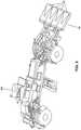
- FIG. 3depicts an embodiment mounted on a vehicle 100.
- Panel 10 containing a UWB GPR system for detecting shallow objectscan be mounted on the front of the vehicle 100.
- FIG. 3shows the panel 10 mounted to the front of the vehicle 100, in other embodiments consistent with this disclosure, the panel 10 can be mounted elsewhere on the vehicle 100.
- Multiple resistive vee dipole antenna assemblies 20can be disposed on the top of the panel 10.
- Antenna assembliescan also be disposed on the bottom of panel 10.
- the antennas of assemblies 20can be larger than the antennas 1 located inside the panel 10. The larger antennas can be employed for operation with lower center frequency signals than the signals transmitted and received by the smaller antennas 1.
- the lower frequency pulses transmitted and received by the large antennasmay provide GPR images of larger, more deeply buried objects, while the higher frequency pulses transmitted and received by small antennas 1 may image smaller and shallower objects. Aside from the difference in frequency, the larger antennas can be used in a similar fashion as described above with respect to the smaller antennas 1.
- a processor modulecan provide input signals to transmitting antennas for emission into the ground. The processor module can also receive reflected signals from receiving antennas, perform signal processing on them, and output data to a processor or display for a user.
- an antenna assembly 20When an antenna assembly 20 is oriented as shown in FIG. 3 , its focus and field of view may be into the ground. Panel 10 may be fixed in place, or its orientation with respect to the ground may be adjustable.
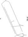
- Figures 4A-4Cprovide detailed views from multiple angles of the large antenna assembly 20 and its orientation with respect to the smaller antennas 1, according to an embodiment consistent with this disclosure.
- An antenna assembly 20can comprise antennas 21, coupling feedbox 23, and transmission line 22.
- the shape, size, and materials of the antennas 21can be selected to provide a large aperture suitable for low-frequency operations and a low radar cross-section.
- the embodiments of Figures 4A-4Ccan use resistive vee dipole antennas because they have these characteristics.
- a low radar cross-sectionmay reduce coupling between the large antennas 21 and the smaller antennas 1. Therefore, it can be possible to search for large, deep objects and small, shallow objects simultaneously.
- the views of Figures 4A-4Cdepict two large antenna assemblies 20 per view.
- a transmitting antennacan be located on one side of the panel 10 and a receiving antenna can be located on the other side of the panel 10.
- a transmitting antenna 21can be on the top and a receiving antenna 21 can be on the bottom, or a receiving antenna 21 can be on the top and a transmitting antenna 21 can be on the bottom. It will be understood by one skilled in the relevant art that other antenna arrangements can be possible. For example, both transmitting and receiving antennas 21 can be located on the same side (either the top or the bottom) of the panel 10.
- FIG. 5depicts an embodiment mounted on a vehicle 100.
- Panel 10, containing an existing UWB GPR system for detecting shallow objectscan be mounted on the front of the vehicle 100.
- a secondary panel 11can extend from the bottom of panel 10.
- this secondary panel 11can be a wedge-shaped enclosure which can contain or provide a mounting surface for the antennas of assemblies 20.
- the secondary panel 11can be a flat panel extending from the panel 10 and oriented in a vertical direction, or the angle between the panel 10 and the secondary panel 11 can be different in other embodiments of the invention.
- Multiple resistive vee dipole antenna assemblies 20can be disposed on a flat side of a wedge-shaped secondary panel 11, within a wedge-shaped secondary panel 11, or on either side of a flat secondary panel 11. As in the embodiment of FIG. 3 , the antennas of assemblies 20 can be much larger than the antennas 1 located inside the panel 10. The larger antennas can be suited for operation with lower center frequency signals than the signals transmitted and received by the smaller antennas 1. The low frequency pulses transmitted and received by the large antennas can provide GPR images of large, deeply buried objects, while the higher frequency pulses transmitted and received by small antennas 1 can image smaller and shallower objects. When an antenna assembly 20 is oriented as shown in FIG. 5 , its focus and field of view can be into the ground.
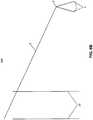
- Figures 6A-6Bprovide detailed views from multiple angles of the large antenna assembly 20 and their orientation with respect to the smaller antennas 1, according to an embodiment consistent with this disclosure.
- An antenna assembly 20can consist of antennas 21, coupling feedboxes 23, and transmission lines 22.
- resistive vee dipole antennascan be used in the embodiments of Figures 6A-6B in order to reduce coupling between the large antennas 21 and the small antennas 1 and allow for simultaneous detection of large, deep objects and small, shallow objects.
- the views of Figures 6A-6Bdepict two large antennas 21 per view.
- a secondary panel 11can be present, and a transmitting antenna can be located on one side of the secondary panel 11 and a receiving antenna can be located on the other side of the secondary panel 11.
- a transmitting antenna 21can be on a front side of the secondary panel 11 and a receiving antenna 21 can be on a rear side of the secondary panel 11, or a receiving antenna 21 can be on the front side and a transmitting antenna 21 can be on the rear side.
- Antenna assembly 20can be oriented with one antenna 21 directly across from another antenna 21 on opposite sides of the panel 10 or secondary panel 11, as shown, or the antennas 21 can be arranged so as not to be directly aligned.
- An angle between the poles of the antenna 21can be narrow to provide a highly directional GPR signal, or the angle can be wide to provide a less directional GPR signal with a wider field of view.
- antennas 21can be oriented in a wide range of directions in the embodiment of Figures 4A-4C .
- the GPR signalcan be directed into the ground by the transmitting antenna 21 at a nearly perpendicular angle to the surface of the ground at one extreme or a more nearly parallel angle to the surface of the ground at the other extreme.
- non-equal numbers of transmitting antennas 21 and receiving antennas 21can be provided. Some embodiments can direct high frequency GPR signals and low frequency GPR signals to the same ground surface location at the same time, whereas other embodiments can direct the different signals to different locations. In these latter embodiments, the return images can be collocated for presentation to a user, or they can be kept separate.
- the antenna assembly 20can comprise an antenna 21 formed on a rigid or flexible substrate, or antennas 21 can be constructed without a substrate or other backing and installed directly on the panel 10 or secondary panel 11.
- the angle between poles of the antenna 21can be variable.
- Signal noisemay be compensated for in some embodiments through the interposition of radar-absorbing materials between the antennas 21 and the vehicle 100, through the use of algorithmic filtering during processing of received signals, or by other techniques.
- Some embodiments consistent with the disclosurecan optionally be employed as modifications to existing GPR arrays, and other embodiments can be new GPR arrays.
Landscapes
- Physics & Mathematics (AREA)
- Engineering & Computer Science (AREA)
- Remote Sensing (AREA)
- Life Sciences & Earth Sciences (AREA)
- Electromagnetism (AREA)
- General Physics & Mathematics (AREA)
- Radar, Positioning & Navigation (AREA)
- Environmental & Geological Engineering (AREA)
- Geology (AREA)
- General Life Sciences & Earth Sciences (AREA)
- Geophysics (AREA)
- Computer Networks & Wireless Communication (AREA)
- Variable-Direction Aerials And Aerial Arrays (AREA)
- Radar Systems Or Details Thereof (AREA)
- Details Of Aerials (AREA)
- Geophysics And Detection Of Objects (AREA)
Description
- The present disclosure relates to radar arrays and methods for detecting objects.
- Ultra-wide bandwidth (UWB) antennas can be used in ground penetrating radar (GPR) arrays for detection of buried objects and threats such as mines and improvised explosive devices (IEDs). An exemplary UWB GPR system can be found in Wichmann (
U.S. Patent No. 7,042, 385 ).US2010277397 discloses detection of surface and buried objects.Mark P Kolba et al: A Framework for Information-Based Sensor Management for the Detection of Static Targets, IEEE Transaction on Systems, Man and Cybernetics. Part A: Systems and Humans, IEEE Service Center, Piscataway, NJ, US, vol. 41, no. 1, 1 January 2011 (2011-01-01), pages 105- 120, XP011317614, ISSN: 1083-4427 discloses detection of static targets.US 2010/0066585 discloses a ground penetrating radar system that is able to create both low frequency, wide pulses, and high frequency, narrow pulses, to enable both deep and shallow operation of the ground penetrating radar on demand, including simultaneous operation. - In one aspect, embodiments provide a radar array, comprising a panel, the panel comprising a top side and a bottom side; a plurality of high-frequency antennas coupled into a high-frequency array coupled to the panel; at least one low-frequency resistive vee dipole transmitting antenna; and at least one low-frequency resistive vee dipole receiving antenna, wherein the at least one low-frequency resistive vee dipole transmitting antenna and the at least one low-frequency resistive vee dipole receiving antenna are coupled into a low-frequency array, the low-frequency array being disposed on the panel; wherein at least one of the plurality of high-frequency antennas is a high-frequency transmitting antenna operable to transmit a first signal having a first center frequency; wherein the at least one low-frequency resistive vee dipole transmitting antenna is operable to transmit a second signal having a lower center frequency than the first center frequency; and wherein the low-frequency array can be oriented in a range of directions to direct the transmitted signal into the ground at a nearly perpendicular angle to the surface of the ground at one extreme, or a more nearly parallel angle to the surface of the ground at the other extreme
- In another aspect, embodiments provide a method for detecting objects buried beneath a surface of a medium, comprising drawing a high-frequency array and a low frequency array across the surface; transmitting a plurality of high-frequency pulses of electromagnetic radiation with the high-frequency array; transmitting a plurality of low-frequency pulses of electromagnetic radiation with the low-frequency array; receiving the plurality of high-frequency pulses with the high-frequency array after interaction with the medium; receiving the plurality of low-frequency pulses with the low-frequency array after interaction with the medium; processing the plurality of high-frequency pulses; and processing the plurality of low-frequency pulses; wherein the high frequency-array comprises a plurality of high frequency antennas and the low-frequency array comprises at least one-low frequency resistive vee dipole transmittal antenna and at least one low-frequency resistive vee dipole receiving antenna; wherein at least one of the plurality of high-frequency antennas is a high-frequency transmitting antenna operable to transmit a first signal having a first center frequency; wherein the at least one low-frequency resistive vee dipole transmitting antenna is operable to transmit a second signal having a lower center frequency than the first center frequency; and wherein the low-frequency array can be oriented in a range of directions to direct the transmitted signal into the ground at a nearly perpendicular angle to the surface of the ground at one extreme, or a more nearly parallel angle to the surface of the ground at the other extreme; optionally further comprising generating data from the processing of the plurality of high-frequency pulses and the processing of low-frequency pulses; and displaying the data to a user..
FIG. 1 depicts an element of a vee dipole array and a vee dipole array deployed on a motorized vehicle;FIG. 2 depicts several views of a vee dipole array;FIG. 3 depicts a large resistive vee dipole antenna combined with a vee dipole array deployed on a motorized vehicle;FIG. 4A depicts a schematic perspective view of a large resistive vee dipole antenna combined with a vee dipole array;FIG. 4B depicts an alternate schematic perspective view of a large resistive vee dipole antenna combined with a vee dipole array;FIG. 4C depicts a schematic side elevation view of a large resistive vee dipole antenna combined with a vee dipole array;FIG. 5 depicts a large resistive vee dipole antenna combined with a vee dipole array deployed on a motorized vehicle;FIG. 6A depicts a schematic perspective view of a large resistive vee dipole antenna combined with a vee dipole array; andFIG. 6B depicts a schematic side elevation view of a large resistive vee dipole antenna combined with a vee dipole array.- As mentioned above, UWB antennas can be used in GPR arrays for detection of buried objects and threats such as mines and IEDs. Depending upon the antenna geometry and the frequency content of the driving pulses used in a GPR system, the center frequency can be tuned to find large, deep objects, or small, shallow objects. The arrangement described herein can be used to find small, shallow objects as well as large, deep objects. Embodiments consistent with this disclosure can combine a lower center frequency UWB GPR array with a higher center frequency UWB GPR array to yield a wider overall bandwidth. This combination can provide for the detection of large, deeply buried objects with the low center frequency array and the detection of small, shallow objects with the high center frequency array. In embodiments consistent with this disclosure, the lower center frequency UWB GPR array can be integrated into presently existing high frequency arrays without changing the current panel design.
FIG. 1 depicts a UWB GPR system for detecting shallow objects. Aresistive vee antenna 1 can be used to transmit and/or receive pulses of electromagnetic radiation. Theantenna 1 can be a highly resistive, low metal content antenna. The legs of theantenna 1 can be tapered, increasing along each leg of thevee antenna 1 toward the proximal end, so as to create a resistively tapered vee (RTV) antenna. This taper can be linear in order to vary impedance gradually and thereby reduce reflection across a broad spectral band. Theantenna 1 can be connected to acoupling feedbox 2, which in turn can be connected to atransmission line 3, which in turn can be connected to a multiplexer and subsequent processor module 4. These elements can be contained in apanel 10 which may be mounted to avehicle 100. Thetransmission line 3 can be made long and straight, and can be rigidly attached to a flat surface. This can maintain transmission line elements formultiple antennas 1 in parallel while allowing theantennas 1 to be placed far from thevehicle 100, thereby reducing signal interference from the vehicle. Theantenna 1 is depicted as a vee inFIG. 1 , having a focus and field of view that can be oriented primarily towards the ground. This can reduce signals reflected by the framework holding theantenna 1. However, other antenna configurations, such as a resistive dipole 5, rod 6, or spiral 7 can be used in alternate embodiments.FIG. 2 depicts apanel 10 which can be used in a UWB GPR system for detecting shallow objects. As inFIG. 1 , anantenna 1 can be connected to acoupling feedbox 2, which in turn can be connected to atransmission line 3, which in turn can be connected to a multiplexer and subsequent processor module 4. Theantenna 1,feedbox 2, andtransmission line 3 can be disposed on low radar cross section (LRC) sheets ofplastic 45.Multiple sheets 45, each containing anantenna 1,feedbox 2, andtransmission line 3, can constitute an antenna array with themultiple transmission lines 3 being fed into the multiplexer and subsequent processor module 4. The processor module 4 can provide input signals to transmittingantennas 1 for emission into the ground. The processor module 4 can also receive reflected signals from receivingantennas 1, perform signal processing on them (which can include removal of known self-signature noise), and output data to a processor or display for a user (not pictured). Sheets ofLRC foam 46 separate the LRC sheets ofplastic 45. TheLRC elements plastic frame 48 and can be fastened to angled metal or high-strengthplastic members 47. When fastened to one another, theLRC elements frame 48 can form thepanel 10.FIG. 3 depicts an embodiment mounted on avehicle 100.Panel 10 containing a UWB GPR system for detecting shallow objects can be mounted on the front of thevehicle 100. ThoughFIG. 3 shows thepanel 10 mounted to the front of thevehicle 100, in other embodiments consistent with this disclosure, thepanel 10 can be mounted elsewhere on thevehicle 100. Multiple resistive veedipole antenna assemblies 20 can be disposed on the top of thepanel 10. Antenna assemblies can also be disposed on the bottom ofpanel 10. The antennas ofassemblies 20 can be larger than theantennas 1 located inside thepanel 10. The larger antennas can be employed for operation with lower center frequency signals than the signals transmitted and received by thesmaller antennas 1. The lower frequency pulses transmitted and received by the large antennas may provide GPR images of larger, more deeply buried objects, while the higher frequency pulses transmitted and received bysmall antennas 1 may image smaller and shallower objects. Aside from the difference in frequency, the larger antennas can be used in a similar fashion as described above with respect to thesmaller antennas 1. A processor module can provide input signals to transmitting antennas for emission into the ground. The processor module can also receive reflected signals from receiving antennas, perform signal processing on them, and output data to a processor or display for a user. When anantenna assembly 20 is oriented as shown inFIG. 3 , its focus and field of view may be into the ground.Panel 10 may be fixed in place, or its orientation with respect to the ground may be adjustable.Figures 4A-4C provide detailed views from multiple angles of thelarge antenna assembly 20 and its orientation with respect to thesmaller antennas 1, according to an embodiment consistent with this disclosure. Anantenna assembly 20 can compriseantennas 21,coupling feedbox 23, andtransmission line 22. The shape, size, and materials of theantennas 21 can be selected to provide a large aperture suitable for low-frequency operations and a low radar cross-section. The embodiments ofFigures 4A-4C can use resistive vee dipole antennas because they have these characteristics. A low radar cross-section may reduce coupling between thelarge antennas 21 and thesmaller antennas 1. Therefore, it can be possible to search for large, deep objects and small, shallow objects simultaneously. The views ofFigures 4A-4C depict twolarge antenna assemblies 20 per view. This represents an embodiment of the invention wherein a transmitting antenna can be located on one side of thepanel 10 and a receiving antenna can be located on the other side of thepanel 10. A transmittingantenna 21 can be on the top and a receivingantenna 21 can be on the bottom, or a receivingantenna 21 can be on the top and a transmittingantenna 21 can be on the bottom. It will be understood by one skilled in the relevant art that other antenna arrangements can be possible. For example, both transmitting and receivingantennas 21 can be located on the same side (either the top or the bottom) of thepanel 10.FIG. 5 depicts an embodiment mounted on avehicle 100.Panel 10, containing an existing UWB GPR system for detecting shallow objects can be mounted on the front of thevehicle 100. Asecondary panel 11 can extend from the bottom ofpanel 10. In the example ofFIG. 5 , thissecondary panel 11 can be a wedge-shaped enclosure which can contain or provide a mounting surface for the antennas ofassemblies 20. In other embodiments, thesecondary panel 11 can be a flat panel extending from thepanel 10 and oriented in a vertical direction, or the angle between thepanel 10 and thesecondary panel 11 can be different in other embodiments of the invention. Multiple resistive veedipole antenna assemblies 20 can be disposed on a flat side of a wedge-shapedsecondary panel 11, within a wedge-shapedsecondary panel 11, or on either side of a flatsecondary panel 11. As in the embodiment ofFIG. 3 , the antennas ofassemblies 20 can be much larger than theantennas 1 located inside thepanel 10. The larger antennas can be suited for operation with lower center frequency signals than the signals transmitted and received by thesmaller antennas 1. The low frequency pulses transmitted and received by the large antennas can provide GPR images of large, deeply buried objects, while the higher frequency pulses transmitted and received bysmall antennas 1 can image smaller and shallower objects. When anantenna assembly 20 is oriented as shown inFIG. 5 , its focus and field of view can be into the ground.Figures 6A-6B provide detailed views from multiple angles of thelarge antenna assembly 20 and their orientation with respect to thesmaller antennas 1, according to an embodiment consistent with this disclosure. Anantenna assembly 20 can consist ofantennas 21,coupling feedboxes 23, andtransmission lines 22. Similarly to the embodiments ofFigures 4A-4C , resistive vee dipole antennas can be used in the embodiments ofFigures 6A-6B in order to reduce coupling between thelarge antennas 21 and thesmall antennas 1 and allow for simultaneous detection of large, deep objects and small, shallow objects. The views ofFigures 6A-6B depict twolarge antennas 21 per view. This represents an embodiment consistent with this disclosure wherein asecondary panel 11 can be present, and a transmitting antenna can be located on one side of thesecondary panel 11 and a receiving antenna can be located on the other side of thesecondary panel 11. A transmittingantenna 21 can be on a front side of thesecondary panel 11 and a receivingantenna 21 can be on a rear side of thesecondary panel 11, or a receivingantenna 21 can be on the front side and a transmittingantenna 21 can be on the rear side.- Several embodiments are possible with variations on the embodiments of
Figures 4A-4C andFigures 6A-6B .Antenna assembly 20 can be oriented with oneantenna 21 directly across from anotherantenna 21 on opposite sides of thepanel 10 orsecondary panel 11, as shown, or theantennas 21 can be arranged so as not to be directly aligned. An angle between the poles of theantenna 21 can be narrow to provide a highly directional GPR signal, or the angle can be wide to provide a less directional GPR signal with a wider field of view. Additionally,antennas 21 can be oriented in a wide range of directions in the embodiment ofFigures 4A-4C . For example, the GPR signal can be directed into the ground by the transmittingantenna 21 at a nearly perpendicular angle to the surface of the ground at one extreme or a more nearly parallel angle to the surface of the ground at the other extreme. In some embodiments, non-equal numbers of transmittingantennas 21 and receivingantennas 21 can be provided. Some embodiments can direct high frequency GPR signals and low frequency GPR signals to the same ground surface location at the same time, whereas other embodiments can direct the different signals to different locations. In these latter embodiments, the return images can be collocated for presentation to a user, or they can be kept separate. Theantenna assembly 20 can comprise anantenna 21 formed on a rigid or flexible substrate, orantennas 21 can be constructed without a substrate or other backing and installed directly on thepanel 10 orsecondary panel 11. In these embodiments, the angle between poles of theantenna 21 can be variable. Signal noise may be compensated for in some embodiments through the interposition of radar-absorbing materials between theantennas 21 and thevehicle 100, through the use of algorithmic filtering during processing of received signals, or by other techniques. Some embodiments consistent with the disclosure can optionally be employed as modifications to existing GPR arrays, and other embodiments can be new GPR arrays.
Claims (13)
- A radar array comprising:a panel (10), the panel comprising a top side and a bottom side;at least one resistive vee dipole transmitting antenna; andat least one resistive vee dipole receiving antenna,wherein the at least one resistive vee dipole transmitting antenna and the at least one resistive vee dipole receiving antenna are coupled into an array, the array being disposed on the panel;characterized in thatthe array comprises a plurality of high-frequency antennas (1) coupled into a high-frequency array coupled to the panel (10);wherein the at least one resistive vee dipole transmitting antenna and the at least one resistive vee dipole receiving antenna are low-frequency antennas (21) coupled into a low-frequency array (20) disposed on the panel;wherein at least one of the plurality of high-frequency antennas (1) is a high-frequency transmitting antenna operable to transmit a first signal having a first center frequency;wherein the at least one low-frequency resistive vee dipole transmitting antenna (21) is operable to transmit a second signal having a lower center frequency than the first center frequency; andwherein the low-frequency array (20) can be oriented in a range of directions to direct the transmitted signal into the ground at a nearly perpendicular angle to the surface of the ground at one extreme, or a more nearly parallel angle to the surface of the ground at the other extreme.
- The radar array of claim 1,
wherein the at least one low-frequency resistive vee dipole transmitting antenna (21) is disposed on the top side; and
wherein the at least one low-frequency resistive vee dipole receiving antenna (21) is disposed on the bottom side. - The radar array of claim 1,
wherein the at least one low-frequency resistive vee dipole receiving antenna (21) is disposed on the top side; and
wherein the at least one low-frequency resistive vee dipole transmitting antenna (21) is disposed on the bottom side. - The radar array of claim 1,
wherein the at least one low-frequency resistive vee dipole receiving antenna (21) is disposed on the top side; and
wherein the at least one low-frequency resistive vee dipole transmitting antenna (21) is disposed on the top side. - The radar array of claim 1,
wherein the at least one low-frequency resistive vee dipole receiving antenna (21) is disposed on the bottom side; and
wherein the at least one low-frequency resistive vee dipole transmitting antenna (21) is disposed on the bottom side. - The radar array of claim 1, further comprising:
a secondary panel (11) extending downward from the bottom side. - The radar array of claim 6,
wherein the secondary panel (11) comprises at least one flat side;
wherein the at least one low-frequency resistive vee dipole transmitting antenna (21) is disposed on the at least one flat side; and
wherein the at least one low-frequency resistive vee dipole receiving antenna (21) is disposed on the at least one flat side; or .
wherein the at least one low-frequency resistive vee dipole transmitting antenna (21) is disposed inside the secondary panel; and
wherein the at least one low-frequency resistive vee dipole receiving antenna (21) is disposed inside the secondary panel; or
wherein the secondary panel (11) comprises a front side and a rear side. - The radar array of claim 7,
wherein the at least one low-frequency resistive vee dipole transmitting antenna (21) is disposed on the front side; and
wherein the at least one low-frequency resistive vee dipole receiving antenna (21) is disposed on the rear side; or
wherein the at least one low-frequency resistive vee dipole receiving antenna (21) is disposed on the front side; and
wherein the at least one low-frequency resistive vee dipole transmitting antenna (21) is disposed on the rear side; or
wherein the at least one low-frequency resistive vee dipole receiving antenna (21) is disposed on the front side; and
wherein the at least one low-frequency resistive vee dipole transmitting antenna (21) is disposed on the front side; or
wherein the at least one low-frequency resistive vee dipole receiving antenna (21) is disposed on the rear side; and
wherein the at least one low-frequency resistive vee dipole transmitting antenna (21) is disposed on the rear side. - The radar array of claim 1, wherein the plurality of high-frequency antennas (1) are high-frequency resistive vee dipole antennas.
- The radar array of claim 1, wherein the panel is mounted to a vehicle (100), optionally wherein the panel (10) has an adjustable orientation.
- The radar array of claim 1, wherein the at least one low-frequency resistive vee dipole transmitting antenna (21) and the at least one low-frequency resistive vee dipole receiving antenna (21) are formed on at least one substrate.
- The radar array of claim 1,
wherein the at least one low-frequency resistive vee dipole transmitting antenna (21) comprises at least one pair of transmitting antenna poles, and
wherein the at least one low-frequency resistive vee dipole receiving antenna (21) comprises at least one pair of receiving antenna poles, optionally wherein each of the transmitting antenna poles and receiving antenna poles is tapered; or
wherein an at least one first angle between each pair of transmitting antenna poles is adjustable, and
wherein an at least one second angle between each pair of receiving antenna poles is adjustable. - A method for detecting objects buried beneath a surface of a medium comprising:drawing an array across the surface;transmitting a plurality of pulses of electromagnetic radiation with the array;receiving the plurality of pulses with the array after interaction with the medium;processing the plurality of pulses;characterized in thatthe array comprises a high-frequency array and a low-frequency array;the method comprising:transmitting a plurality of high-frequency pulses of electromagnetic radiation with the high-frequency array;transmitting a plurality of low-frequency pulses of electromagnetic radiation with the low-frequency array;receiving the plurality of high-frequency pulses with the high-frequency array after interaction with the medium;receiving the plurality of low-frequency pulses with the low-frequency array after interaction with the medium;processing the plurality of high-frequency pulses; andprocessing the plurality of low-frequency pulses;wherein the high frequency-array comprises a plurality of high frequency antennas and the low-frequency array comprises at least one-low frequency resistive vee dipole transmittal antenna and at least one low-frequency resistive vee dipole receiving antenna;wherein at least one of the plurality of high-frequency antennas is a high-frequency transmitting antenna operable to transmit a first signal having a first center frequency;wherein the at least one low-frequency resistive vee dipole transmitting antenna is operable to transmit a second signal having a lower center frequency than the first center frequency; andwherein the low-frequency array can be oriented in a range of directions to direct the transmitted signal into the ground at a nearly perpendicular angle to the surface of the ground at one extreme, or a more nearly parallel angle to the surface of the ground at the other extreme;optionally further comprising generating data from the processing of the plurality of high-frequency pulses and the processing of low-frequency pulses; and displaying the data to a user.
Applications Claiming Priority (2)
| Application Number | Priority Date | Filing Date | Title |
|---|---|---|---|
| US201161490910P | 2011-05-27 | 2011-05-27 | |
| PCT/US2012/039627WO2012166616A1 (en) | 2011-05-27 | 2012-05-25 | Large resistive vee dipole antenna combined with vee dipole array |
Publications (2)
| Publication Number | Publication Date |
|---|---|
| EP2715406A1 EP2715406A1 (en) | 2014-04-09 |
| EP2715406B1true EP2715406B1 (en) | 2018-06-27 |
Family
ID=46208183
Family Applications (1)
| Application Number | Title | Priority Date | Filing Date |
|---|---|---|---|
| EP12725590.9ANot-in-forceEP2715406B1 (en) | 2011-05-27 | 2012-05-25 | Large resistive vee dipole antenna combined with vee dipole array |
Country Status (10)
| Country | Link |
|---|---|
| US (2) | US9671494B2 (en) |
| EP (1) | EP2715406B1 (en) |
| JP (1) | JP6169565B2 (en) |
| KR (1) | KR101990016B1 (en) |
| AU (3) | AU2012262519A1 (en) |
| DK (1) | DK2715406T3 (en) |
| ES (1) | ES2688344T3 (en) |
| IL (1) | IL229186A0 (en) |
| PT (1) | PT2715406T (en) |
| WO (1) | WO2012166616A1 (en) |
Families Citing this family (3)
| Publication number | Priority date | Publication date | Assignee | Title |
|---|---|---|---|---|
| US9207307B2 (en)* | 2011-11-21 | 2015-12-08 | Stolar, Inc. | Large area ground monitoring |
| WO2014055732A2 (en) | 2012-10-04 | 2014-04-10 | Whaley Brian A | Shieldings for metal detector heads and manufacturing methods thereof |
| CN110031902A (en)* | 2019-03-25 | 2019-07-19 | 迁西县贺辰物探科技有限公司 | A kind of high-efficiency multi-function physical prospecting instrument |
Citations (1)
| Publication number | Priority date | Publication date | Assignee | Title |
|---|---|---|---|---|
| US20100066585A1 (en)* | 2007-09-19 | 2010-03-18 | Niitek , Inc | Adjustable pulse width ground penetrating radar |
Family Cites Families (8)
| Publication number | Priority date | Publication date | Assignee | Title |
|---|---|---|---|---|
| JPH0470588A (en)* | 1990-07-11 | 1992-03-05 | Komatsu Ltd | Underground inspection device |
| US5720354A (en)* | 1996-01-11 | 1998-02-24 | Vermeer Manufacturing Company | Trenchless underground boring system with boring tool location |
| US7545865B2 (en)* | 2002-12-03 | 2009-06-09 | M/A-Com, Inc. | Apparatus, methods and articles of manufacture for wideband signal processing |
| US7042385B1 (en)* | 2003-09-16 | 2006-05-09 | Niitek, Inc. | Non-intrusive inspection impulse radar antenna |
| TWI373925B (en)* | 2004-02-10 | 2012-10-01 | Tridev Res L L C | Tunable resonant circuit, tunable voltage controlled oscillator circuit, tunable low noise amplifier circuit and method of tuning a resonant circuit |
| US7659847B2 (en)* | 2006-06-29 | 2010-02-09 | Stolar, Inc. | Radar mining guidance control system |
| WO2010101631A1 (en)* | 2009-03-03 | 2010-09-10 | Waymond Scott | Detection of surface and buried objects |
| US8933841B2 (en)* | 2010-12-13 | 2015-01-13 | The Governing Council Of The University Of Toronto | System and method for localization |
- 2012
- 2012-05-25WOPCT/US2012/039627patent/WO2012166616A1/enunknown
- 2012-05-25EPEP12725590.9Apatent/EP2715406B1/ennot_activeNot-in-force
- 2012-05-25KRKR1020137034042Apatent/KR101990016B1/ennot_activeExpired - Fee Related
- 2012-05-25ESES12725590.9Tpatent/ES2688344T3/enactiveActive
- 2012-05-25PTPT12725590Tpatent/PT2715406T/enunknown
- 2012-05-25USUS13/481,040patent/US9671494B2/ennot_activeExpired - Fee Related
- 2012-05-25AUAU2012262519Apatent/AU2012262519A1/ennot_activeAbandoned
- 2012-05-25DKDK12725590.9Tpatent/DK2715406T3/enactive
- 2012-05-25JPJP2014512149Apatent/JP6169565B2/ennot_activeExpired - Fee Related
- 2013
- 2013-10-31ILIL229186Apatent/IL229186A0/enunknown
- 2016
- 2016-01-27AUAU2016200444Apatent/AU2016200444B2/ennot_activeCeased
- 2017
- 2017-05-02USUS15/584,366patent/US10473779B2/ennot_activeExpired - Fee Related
- 2017-09-05AUAU2017225004Apatent/AU2017225004B2/ennot_activeCeased
Patent Citations (1)
| Publication number | Priority date | Publication date | Assignee | Title |
|---|---|---|---|---|
| US20100066585A1 (en)* | 2007-09-19 | 2010-03-18 | Niitek , Inc | Adjustable pulse width ground penetrating radar |
Also Published As
| Publication number | Publication date |
|---|---|
| WO2012166616A1 (en) | 2012-12-06 |
| KR101990016B1 (en) | 2019-06-17 |
| US9671494B2 (en) | 2017-06-06 |
| KR20140035951A (en) | 2014-03-24 |
| EP2715406A1 (en) | 2014-04-09 |
| JP2014519746A (en) | 2014-08-14 |
| US20180329051A1 (en) | 2018-11-15 |
| AU2012262519A1 (en) | 2013-11-21 |
| US20130069814A1 (en) | 2013-03-21 |
| AU2017225004B2 (en) | 2019-01-31 |
| AU2016200444B2 (en) | 2017-09-14 |
| PT2715406T (en) | 2018-10-24 |
| AU2017225004A1 (en) | 2017-09-28 |
| JP6169565B2 (en) | 2017-07-26 |
| AU2016200444A1 (en) | 2016-02-18 |
| US10473779B2 (en) | 2019-11-12 |
| IL229186A0 (en) | 2013-12-31 |
| DK2715406T3 (en) | 2018-10-08 |
| ES2688344T3 (en) | 2018-11-02 |
Similar Documents
| Publication | Publication Date | Title |
|---|---|---|
| EP1934628B1 (en) | Through-wall imaging device | |
| US20140159949A1 (en) | Aircraft comprising an onboard weather radar antenna provided with inclined panels | |
| AU2014317791B2 (en) | Screening system and method | |
| US7986260B2 (en) | Circularly polarized antennas for active holographic imaging through barriers | |
| AU2017225004B2 (en) | Large resistive vee dipole antenna combined with vee dipole array | |
| US20180341005A1 (en) | Radar module, and vehicle radar device comprising same | |
| US9459345B2 (en) | Passive detection of unauthorized electronic devices using wafer scale beam forming | |
| CN105068069A (en) | Millimeter wave three-dimensional holographic imaging device and imaging method | |
| EP1232403B1 (en) | Ground penetrating radar system and method for detecting an object on or below a ground surface | |
| AU2014278240B2 (en) | Multi-elevational antenna systems and methods of use | |
| EP1710860A3 (en) | Multiple-element beam steering antenna | |
| WO2013112223A2 (en) | Detection of an asymmetric object | |
| JP5271784B2 (en) | Search radar antenna | |
| Longstaff et al. | MIMO radar developments at Teledyne Australia | |
| JP6542242B2 (en) | Underground radar antenna system | |
| JPH066566Y2 (en) | Antenna device for underground radar | |
| KR102660646B1 (en) | Landmine detection system and the method thereof | |
| JP2007285899A (en) | Orientation radar equipment | |
| KR101387438B1 (en) | Apparatus for detecting landmine | |
| US20120268346A1 (en) | Biologically inspired beam forming small antenna arrays | |
| Ratcliffe et al. | Cost effective surface penetrating radar device for humanitarian demining | |
| Chougale et al. | Design and development of UHF Moxon antenna | |
| CN113640894A (en) | Double-view-angle millimeter wave transceiving array | |
| Kim et al. | Wideband Antenna for Portable Ground Penetrating Radar System | |
| Kameno | AGN Science with VSOP and Prospects for VSOP-2 |
Legal Events
| Date | Code | Title | Description |
|---|---|---|---|
| PUAI | Public reference made under article 153(3) epc to a published international application that has entered the european phase | Free format text:ORIGINAL CODE: 0009012 | |
| 17P | Request for examination filed | Effective date:20131202 | |
| AK | Designated contracting states | Kind code of ref document:A1 Designated state(s):AL AT BE BG CH CY CZ DE DK EE ES FI FR GB GR HR HU IE IS IT LI LT LU LV MC MK MT NL NO PL PT RO RS SE SI SK SM TR | |
| DAX | Request for extension of the european patent (deleted) | ||
| 17Q | First examination report despatched | Effective date:20160726 | |
| STAA | Information on the status of an ep patent application or granted ep patent | Free format text:STATUS: EXAMINATION IS IN PROGRESS | |
| GRAP | Despatch of communication of intention to grant a patent | Free format text:ORIGINAL CODE: EPIDOSNIGR1 | |
| STAA | Information on the status of an ep patent application or granted ep patent | Free format text:STATUS: GRANT OF PATENT IS INTENDED | |
| RIC1 | Information provided on ipc code assigned before grant | Ipc:G01S 13/88 20060101ALI20171215BHEP Ipc:G01V 3/17 20060101AFI20171215BHEP Ipc:H01Q 9/44 20060101ALI20171215BHEP Ipc:H01Q 21/28 20060101ALI20171215BHEP Ipc:G01S 7/03 20060101ALI20171215BHEP Ipc:G01V 3/12 20060101ALI20171215BHEP | |
| INTG | Intention to grant announced | Effective date:20180109 | |
| GRAS | Grant fee paid | Free format text:ORIGINAL CODE: EPIDOSNIGR3 | |
| GRAA | (expected) grant | Free format text:ORIGINAL CODE: 0009210 | |
| STAA | Information on the status of an ep patent application or granted ep patent | Free format text:STATUS: THE PATENT HAS BEEN GRANTED | |
| AK | Designated contracting states | Kind code of ref document:B1 Designated state(s):AL AT BE BG CH CY CZ DE DK EE ES FI FR GB GR HR HU IE IS IT LI LT LU LV MC MK MT NL NO PL PT RO RS SE SI SK SM TR | |
| REG | Reference to a national code | Ref country code:GB Ref legal event code:FG4D | |
| REG | Reference to a national code | Ref country code:AT Ref legal event code:REF Ref document number:1012809 Country of ref document:AT Kind code of ref document:T Effective date:20180715 | |
| REG | Reference to a national code | Ref country code:IE Ref legal event code:FG4D | |
| REG | Reference to a national code | Ref country code:DE Ref legal event code:R096 Ref document number:602012047819 Country of ref document:DE | |
| REG | Reference to a national code | Ref country code:DK Ref legal event code:T3 Effective date:20181001 | |
| REG | Reference to a national code | Ref country code:NL Ref legal event code:FP | |
| REG | Reference to a national code | Ref country code:SE Ref legal event code:TRGR | |
| REG | Reference to a national code | Ref country code:PT Ref legal event code:SC4A Ref document number:2715406 Country of ref document:PT Date of ref document:20181024 Kind code of ref document:T Free format text:AVAILABILITY OF NATIONAL TRANSLATION Effective date:20180924 | |
| PG25 | Lapsed in a contracting state [announced via postgrant information from national office to epo] | Ref country code:LT Free format text:LAPSE BECAUSE OF FAILURE TO SUBMIT A TRANSLATION OF THE DESCRIPTION OR TO PAY THE FEE WITHIN THE PRESCRIBED TIME-LIMIT Effective date:20180627 Ref country code:FI Free format text:LAPSE BECAUSE OF FAILURE TO SUBMIT A TRANSLATION OF THE DESCRIPTION OR TO PAY THE FEE WITHIN THE PRESCRIBED TIME-LIMIT Effective date:20180627 Ref country code:BG Free format text:LAPSE BECAUSE OF FAILURE TO SUBMIT A TRANSLATION OF THE DESCRIPTION OR TO PAY THE FEE WITHIN THE PRESCRIBED TIME-LIMIT Effective date:20180927 | |
| REG | Reference to a national code | Ref country code:ES Ref legal event code:FG2A Ref document number:2688344 Country of ref document:ES Kind code of ref document:T3 Effective date:20181102 | |
| REG | Reference to a national code | Ref country code:LT Ref legal event code:MG4D Ref country code:NO Ref legal event code:T2 Effective date:20180627 | |
| PG25 | Lapsed in a contracting state [announced via postgrant information from national office to epo] | Ref country code:RS Free format text:LAPSE BECAUSE OF FAILURE TO SUBMIT A TRANSLATION OF THE DESCRIPTION OR TO PAY THE FEE WITHIN THE PRESCRIBED TIME-LIMIT Effective date:20180627 Ref country code:LV Free format text:LAPSE BECAUSE OF FAILURE TO SUBMIT A TRANSLATION OF THE DESCRIPTION OR TO PAY THE FEE WITHIN THE PRESCRIBED TIME-LIMIT Effective date:20180627 Ref country code:GR Free format text:LAPSE BECAUSE OF FAILURE TO SUBMIT A TRANSLATION OF THE DESCRIPTION OR TO PAY THE FEE WITHIN THE PRESCRIBED TIME-LIMIT Effective date:20180928 Ref country code:HR Free format text:LAPSE BECAUSE OF FAILURE TO SUBMIT A TRANSLATION OF THE DESCRIPTION OR TO PAY THE FEE WITHIN THE PRESCRIBED TIME-LIMIT Effective date:20180627 | |
| REG | Reference to a national code | Ref country code:AT Ref legal event code:MK05 Ref document number:1012809 Country of ref document:AT Kind code of ref document:T Effective date:20180627 | |
| PG25 | Lapsed in a contracting state [announced via postgrant information from national office to epo] | Ref country code:SK Free format text:LAPSE BECAUSE OF FAILURE TO SUBMIT A TRANSLATION OF THE DESCRIPTION OR TO PAY THE FEE WITHIN THE PRESCRIBED TIME-LIMIT Effective date:20180627 Ref country code:RO Free format text:LAPSE BECAUSE OF FAILURE TO SUBMIT A TRANSLATION OF THE DESCRIPTION OR TO PAY THE FEE WITHIN THE PRESCRIBED TIME-LIMIT Effective date:20180627 Ref country code:EE Free format text:LAPSE BECAUSE OF FAILURE TO SUBMIT A TRANSLATION OF THE DESCRIPTION OR TO PAY THE FEE WITHIN THE PRESCRIBED TIME-LIMIT Effective date:20180627 Ref country code:IS Free format text:LAPSE BECAUSE OF FAILURE TO SUBMIT A TRANSLATION OF THE DESCRIPTION OR TO PAY THE FEE WITHIN THE PRESCRIBED TIME-LIMIT Effective date:20181027 Ref country code:AT Free format text:LAPSE BECAUSE OF FAILURE TO SUBMIT A TRANSLATION OF THE DESCRIPTION OR TO PAY THE FEE WITHIN THE PRESCRIBED TIME-LIMIT Effective date:20180627 Ref country code:PL Free format text:LAPSE BECAUSE OF FAILURE TO SUBMIT A TRANSLATION OF THE DESCRIPTION OR TO PAY THE FEE WITHIN THE PRESCRIBED TIME-LIMIT Effective date:20180627 Ref country code:CZ Free format text:LAPSE BECAUSE OF FAILURE TO SUBMIT A TRANSLATION OF THE DESCRIPTION OR TO PAY THE FEE WITHIN THE PRESCRIBED TIME-LIMIT Effective date:20180627 | |
| PG25 | Lapsed in a contracting state [announced via postgrant information from national office to epo] | Ref country code:SM Free format text:LAPSE BECAUSE OF FAILURE TO SUBMIT A TRANSLATION OF THE DESCRIPTION OR TO PAY THE FEE WITHIN THE PRESCRIBED TIME-LIMIT Effective date:20180627 | |
| REG | Reference to a national code | Ref country code:DE Ref legal event code:R097 Ref document number:602012047819 Country of ref document:DE | |
| PLBE | No opposition filed within time limit | Free format text:ORIGINAL CODE: 0009261 | |
| STAA | Information on the status of an ep patent application or granted ep patent | Free format text:STATUS: NO OPPOSITION FILED WITHIN TIME LIMIT | |
| 26N | No opposition filed | Effective date:20190328 | |
| PG25 | Lapsed in a contracting state [announced via postgrant information from national office to epo] | Ref country code:SI Free format text:LAPSE BECAUSE OF FAILURE TO SUBMIT A TRANSLATION OF THE DESCRIPTION OR TO PAY THE FEE WITHIN THE PRESCRIBED TIME-LIMIT Effective date:20180627 | |
| PG25 | Lapsed in a contracting state [announced via postgrant information from national office to epo] | Ref country code:AL Free format text:LAPSE BECAUSE OF FAILURE TO SUBMIT A TRANSLATION OF THE DESCRIPTION OR TO PAY THE FEE WITHIN THE PRESCRIBED TIME-LIMIT Effective date:20180627 | |
| REG | Reference to a national code | Ref country code:DE Ref legal event code:R119 Ref document number:602012047819 Country of ref document:DE | |
| REG | Reference to a national code | Ref country code:NO Ref legal event code:MMEP | |
| REG | Reference to a national code | Ref country code:CH Ref legal event code:PL | |
| REG | Reference to a national code | Ref country code:DK Ref legal event code:EBP Effective date:20190531 | |
| REG | Reference to a national code | Ref country code:NL Ref legal event code:MM Effective date:20190601 | |
| GBPC | Gb: european patent ceased through non-payment of renewal fee | Effective date:20190525 | |
| PG25 | Lapsed in a contracting state [announced via postgrant information from national office to epo] | Ref country code:CH Free format text:LAPSE BECAUSE OF NON-PAYMENT OF DUE FEES Effective date:20190531 Ref country code:SE Free format text:LAPSE BECAUSE OF NON-PAYMENT OF DUE FEES Effective date:20190526 Ref country code:MC Free format text:LAPSE BECAUSE OF FAILURE TO SUBMIT A TRANSLATION OF THE DESCRIPTION OR TO PAY THE FEE WITHIN THE PRESCRIBED TIME-LIMIT Effective date:20180627 Ref country code:LI Free format text:LAPSE BECAUSE OF NON-PAYMENT OF DUE FEES Effective date:20190531 Ref country code:NO Free format text:LAPSE BECAUSE OF NON-PAYMENT OF DUE FEES Effective date:20190531 | |
| REG | Reference to a national code | Ref country code:BE Ref legal event code:MM Effective date:20190531 | |
| PG25 | Lapsed in a contracting state [announced via postgrant information from national office to epo] | Ref country code:LU Free format text:LAPSE BECAUSE OF NON-PAYMENT OF DUE FEES Effective date:20190525 | |
| PG25 | Lapsed in a contracting state [announced via postgrant information from national office to epo] | Ref country code:NL Free format text:LAPSE BECAUSE OF NON-PAYMENT OF DUE FEES Effective date:20190601 Ref country code:PT Free format text:LAPSE BECAUSE OF NON-PAYMENT OF DUE FEES Effective date:20200226 Ref country code:GB Free format text:LAPSE BECAUSE OF NON-PAYMENT OF DUE FEES Effective date:20190525 Ref country code:DK Free format text:LAPSE BECAUSE OF NON-PAYMENT OF DUE FEES Effective date:20190531 Ref country code:IE Free format text:LAPSE BECAUSE OF NON-PAYMENT OF DUE FEES Effective date:20190525 Ref country code:DE Free format text:LAPSE BECAUSE OF NON-PAYMENT OF DUE FEES Effective date:20191203 Ref country code:IT Free format text:LAPSE BECAUSE OF NON-PAYMENT OF DUE FEES Effective date:20190525 | |
| REG | Reference to a national code | Ref country code:SE Ref legal event code:EUG | |
| PG25 | Lapsed in a contracting state [announced via postgrant information from national office to epo] | Ref country code:BE Free format text:LAPSE BECAUSE OF NON-PAYMENT OF DUE FEES Effective date:20190531 | |
| PG25 | Lapsed in a contracting state [announced via postgrant information from national office to epo] | Ref country code:FR Free format text:LAPSE BECAUSE OF NON-PAYMENT OF DUE FEES Effective date:20190531 | |
| REG | Reference to a national code | Ref country code:ES Ref legal event code:FD2A Effective date:20200930 | |
| PG25 | Lapsed in a contracting state [announced via postgrant information from national office to epo] | Ref country code:ES Free format text:LAPSE BECAUSE OF NON-PAYMENT OF DUE FEES Effective date:20190526 | |
| PG25 | Lapsed in a contracting state [announced via postgrant information from national office to epo] | Ref country code:CY Free format text:LAPSE BECAUSE OF FAILURE TO SUBMIT A TRANSLATION OF THE DESCRIPTION OR TO PAY THE FEE WITHIN THE PRESCRIBED TIME-LIMIT Effective date:20180627 | |
| PG25 | Lapsed in a contracting state [announced via postgrant information from national office to epo] | Ref country code:HU Free format text:LAPSE BECAUSE OF FAILURE TO SUBMIT A TRANSLATION OF THE DESCRIPTION OR TO PAY THE FEE WITHIN THE PRESCRIBED TIME-LIMIT; INVALID AB INITIO Effective date:20120525 Ref country code:MT Free format text:LAPSE BECAUSE OF FAILURE TO SUBMIT A TRANSLATION OF THE DESCRIPTION OR TO PAY THE FEE WITHIN THE PRESCRIBED TIME-LIMIT Effective date:20180627 | |
| PGFP | Annual fee paid to national office [announced via postgrant information from national office to epo] | Ref country code:TR Payment date:20210518 Year of fee payment:10 | |
| PG25 | Lapsed in a contracting state [announced via postgrant information from national office to epo] | Ref country code:MK Free format text:LAPSE BECAUSE OF FAILURE TO SUBMIT A TRANSLATION OF THE DESCRIPTION OR TO PAY THE FEE WITHIN THE PRESCRIBED TIME-LIMIT Effective date:20180627 | |
| PG25 | Lapsed in a contracting state [announced via postgrant information from national office to epo] | Ref country code:TR Free format text:LAPSE BECAUSE OF NON-PAYMENT OF DUE FEES Effective date:20220525 |