EP2715039B1 - Wellbore junction completion with fluid loss control - Google Patents
Wellbore junction completion with fluid loss controlDownload PDFInfo
- Publication number
- EP2715039B1 EP2715039B1EP12792540.2AEP12792540AEP2715039B1EP 2715039 B1EP2715039 B1EP 2715039B1EP 12792540 AEP12792540 AEP 12792540AEP 2715039 B1EP2715039 B1EP 2715039B1
- Authority
- EP
- European Patent Office
- Prior art keywords
- tubular string
- control device
- flow control
- deflector
- wellbore
- Prior art date
- Legal status (The legal status is an assumption and is not a legal conclusion. Google has not performed a legal analysis and makes no representation as to the accuracy of the status listed.)
- Active
Links
Images


Classifications
- E—FIXED CONSTRUCTIONS
- E21—EARTH OR ROCK DRILLING; MINING
- E21B—EARTH OR ROCK DRILLING; OBTAINING OIL, GAS, WATER, SOLUBLE OR MELTABLE MATERIALS OR A SLURRY OF MINERALS FROM WELLS
- E21B7/00—Special methods or apparatus for drilling
- E21B7/04—Directional drilling
- E21B7/06—Deflecting the direction of boreholes
- E21B7/061—Deflecting the direction of boreholes the tool shaft advancing relative to a guide, e.g. a curved tube or a whipstock
- E—FIXED CONSTRUCTIONS
- E21—EARTH OR ROCK DRILLING; MINING
- E21B—EARTH OR ROCK DRILLING; OBTAINING OIL, GAS, WATER, SOLUBLE OR MELTABLE MATERIALS OR A SLURRY OF MINERALS FROM WELLS
- E21B23/00—Apparatus for displacing, setting, locking, releasing or removing tools, packers or the like in boreholes or wells
- E21B23/08—Introducing or running tools by fluid pressure, e.g. through-the-flow-line tool systems
- E21B23/12—Tool diverters
- E—FIXED CONSTRUCTIONS
- E21—EARTH OR ROCK DRILLING; MINING
- E21B—EARTH OR ROCK DRILLING; OBTAINING OIL, GAS, WATER, SOLUBLE OR MELTABLE MATERIALS OR A SLURRY OF MINERALS FROM WELLS
- E21B41/00—Equipment or details not covered by groups E21B15/00 - E21B40/00
- E21B41/0035—Apparatus or methods for multilateral well technology, e.g. for the completion of or workover on wells with one or more lateral branches
- E21B41/0042—Apparatus or methods for multilateral well technology, e.g. for the completion of or workover on wells with one or more lateral branches characterised by sealing the junction between a lateral and a main bore
Definitions
- This disclosurerelates generally to equipment utilized and operations performed in conjunction with a subterranean well and, in an example described below, more particularly provides a wellbore junction completion with fluid loss control.
- a wellbore junctionprovides for connectivity in a branched or multilateral wellbore.
- Such connectivitycan include sealed fluid communication and/or access between certain wellbore sections.
- US 5,411,082 and US 5,845,707disclose methods of installing a wellbore junction assembly in a well, wherein the junction assembly comprises a tubular string and wherein the methods comprise the steps of inserting a tubular string into a deflector and of providing a seal therebetween.
- the resulting well systemsare also disclosed therein.
- a wellbore junction assemblyincludes a tubular string which is received in a deflector, and opens a flow control device.
- the flow control deviceisolates sections of a wellbore from each other, until the tubular string is installed.
- the inventionprovides a method of installing a wellbore junction assembly in a well as recited in claim 1.
- the inventionprovides a well system as recited in claim 11.
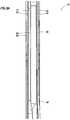
- FIG. 1Representatively illustrated in FIG. 1 is a well system 10 and associated method which can embody principles of this disclosure.
- a wellbore junction 12is formed at an intersection of three wellbore sections 14, 16, 18.
- the wellbore sections 14, 16are part of a "parent" or main wellbore, and the wellbore section 18 is part of a "lateral" or branch wellbore extending outwardly from the main wellbore.
- the wellbore sections 14, 18could form a main wellbore, and the wellbore section 16 could be a branch wellbore.
- more than three wellbore sectionscould intersect at the wellbore junction 12, the wellbore sections 16, 18 could both be branches of the wellbore section 14, etc.
- a wellbore junction assembly 20is installed in the wellbore sections 14, 16, 18 to provide controlled fluid communication and access between the wellbore sections.
- the assembly 20includes a tubular string connector 22, tubular strings 24, 26 attached to an end 28 of the connector, and a tubular string 30 attached to an opposite end 32 of the connector.
- the connector 22provides sealed fluid communication between the tubular string 30 and each of the tubular strings 24, 26.
- physical accessis provided through the connector 22 between the tubular string 30 and at least one of the tubular strings 24, 26.
- a valve or other flow control device 36controls flow longitudinally through a tubular string 40 in the wellbore section 16.
- the wellbore sections 14, 16are lined with casing 42 and cement 44, but the wellbore section 18 is uncased or open hole.
- a window 46is formed through the casing 42 and cement 44, with the wellbore section 18 extending outwardly from the window.
- the wellbore section 18could be lined, with a liner therein being sealingly connected to the window 46 or other portion of the casing 42, etc.
- the scope of this disclosureis not limited to any of the features of the well system 10 or the associated method described herein or depicted in the drawings.
- a deflector 48is secured in the casing 42 at the junction 12 by a packer, latch or other anchor 50.
- the tubular string 40is sealingly secured to the anchor 50 and deflector 48, so that a passage 52 in the tubular string 40 is in communication with a passage 54 in the deflector 48 when the flow control device 36 is open.
- the flow control device 36may be closed, for example, after setting the packer 50 in the wellbore portion 16.
- the tubular string 24is thereafter engaged with seals 56 in the deflector 48, so that the tubular string 24 is in sealed communication with the tubular string 40 in the wellbore section 16.
- a bull nose 58 on a lower end of the tubular string 26is too large to fit into the passage 54 in the deflector 48 and so, when the junction assembly 20 is lowered into the well, the bull nose 58 is deflected laterally into the wellbore section 18.
- the tubular string 24, however,is able to fit into the passage 54 and, when the junction assembly 20 is appropriately positioned as depicted in FIG. 1 , and the flow control device 36 is opened, the tubular string 24 will be in sealed communication with the tubular string 40 via the passage 52.
- fluidssuch as hydrocarbon fluids, oil, gas, water, steam, etc.
- the fluidscan flow via the connector 22 into the tubular string 30 for eventual production to the surface.
- fluidsuch as steam, liquid water, gas, etc.
- another fluidsuch as oil and/or gas, etc.
- fluidscould be injected into both of the wellbore sections 16, 18, etc.
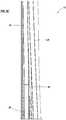
- a partially cross-sectional view of the wellbore junction assembly 20is representatively illustrated, apart from the remainder of the system 10.
- a fluid 60is produced from the wellbore section 16 via the tubular string 24 to the connector 22, and another fluid 62 is produced from the wellbore section 18 via the tubular string 26 to the connector.
- the fluids 60, 62may be the same type of fluid (e.g., oil, gas, steam, water, etc.), or they may be different types of fluids.
- the fluid 62flows via the connector 22 into another tubular string 64 positioned within the tubular string 30.
- the fluid 60flows via the connector 22 into a space 65 formed radially between the tubular strings 30, 64.
- Chokes or other types of flow control devices 66, 68can be used to variably regulate the flows of the fluids 60, 62 into the tubular string 30 above the tubular string 64.
- the devices 66, 68may be remotely controllable by direct, wired or wireless means (e.g., by acoustic, pressure pulse or electromagnetic telemetry, by optical waveguide, electrical conductor or control lines, mechanically, hydraulically, etc.), allowing for an intelligent completion in which production from the various wellbore sections can be independently controlled.
- the fluids 60, 62are depicted in FIG. 2 as being commingled in the tubular string 30 above the tubular string 64, it will be appreciated that the fluids could remain segregated in other examples.
- the device 68is illustrated as possibly obstructing a passage 70 through the tubular string 64, in other examples the device 68 could be positioned so that it effectively regulates flow of the fluid 62 without obstructing the passage.
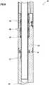
- FIGS. 3A-Edetailed cross-sectional views of the junction assembly 20 as installed in the wellbore sections 14, 16, 18 of the well system 10 are representatively illustrated. For clarity, the remainder of the well system 10 is not illustrated in FIGS. 3A-E .
- FIGS. 3A-Eit may be clearly seen how the features of the junction assembly 20 cooperate to provide for a convenient and effective installation in the wellbore sections 14, 16, 18.
- the tubular string 26has been deflected by the deflector 48 into the wellbore section 18, the tubular string 24 is sealingly received in the seals 56, and the flow control device 36 has been opened in response to inserting the tubular string 24 into the passages 52, 54. Fluid communication is now established between the connector 22 (and the tubular string 30 thereabove) and each of the tubular strings 24, 26.
- the tubular string 24is sealingly engaged with the seals 56 prior to the flow control device 36 being opened.
- sealed fluid communicationis established between the tubular string 24 and the passage 54 prior to opening the flow control device 36, thereby enhancing continued control over pressure and flow communicated to the passage 52 (and formations penetrated below the wellbore section 16) when the flow control device is opened.
- the flow control device 36may be opened using a variety of different techniques, some of which are described below. However, the scope of this disclosure is not limited to the particular techniques for opening the various examples of the flow control device 36 described below, since any method of opening the flow control device may be used in keeping with the scope of this disclosure.
- the flow control device 36opens in response to the tubular string 24 being inserted into the passages 52, 54.
- the flow control device 36is also preferably opened after the tubular string 24 is sealingly engaged with the seals 56.
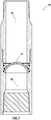
- FIG. 4an enlarged scale cross-sectional view of a section of the junction assembly 20 is representatively illustrated apart from the remainder of the well system 10.
- the flow control device 36is positioned just below the seals 56, so that, when the tubular string 24 is inserted into the passage 54, the tubular string will engage the seals 56 just prior to engaging the flow control device.
- the flow control device 36is similar in some respects to a Glass Disc Sub (Model DP-SDS) marketed by Halliburton Energy Services, Inc. of Houston, Texas USA.
- the flow control device 36includes a frangible barrier 72 (such as glass or ceramic, etc.) which initially prevents fluid communication between the passages 52, 54. When the barrier 72 is broken, fluid communication is permitted between the passages 52, 54.
- the tubular string 24can break the barrier 72 when the tubular string is inserted into the passage 54 (as depicted in FIG. 5 ), or increased pressure in the passage 52 below the flow control device 36 can displace an annular piston 74 to impact the barrier from below.
- Increased pressure in the passage 52 below the flow control device 36could be due to stinging the deflector 48 into the anchor 50. In that case, the barrier 72 could be broken due to the increased pressure, prior to inserting the tubular string 24 into the passage 54.
- the device 36could be operated by applying pressure to a control line or port in communication with a chamber (not shown) exposed to a piston (see FIG. 4 ) of the device. The piston would then displace when pressure in the chamber is increased sufficiently to break shear pins/screws, or another type of releasing device, in order to break the barrier 72.
- the device 36could be turned upside-down, so that the piston of the device is exposed to pressure in the passage 54 above the barrier 72. In this example, increased pressure applied to the passage 54 will cause the piston to displace, in order to break the barrier 72.
- pressure applied to the tubular string 24can be used to apply pressure to the passage 54 (or to another passage, such as a passage extending through a sidewall of the deflector 48, etc.), in order to displace the piston of the device 36 and break the barrier 72.
- junction assembly 20is representatively illustrated.
- the barrier 72is pierced by the tubular string 24 when it is inserted into the passage 52.
- the barrier 72 in this exampleis preferably a severable metal disc, similar to that used in an ANVIL(TM) plugging system marketed by Halliburton Energy Services, Inc.
- the barrier 72is preferably cut by a lower end of the tubular string 24, and folded out of the way, so that the tubular string can extend through it into the passage 52.
- the barrier 72is generally hemispherical in shape, and is preferably made of a ceramic material, so that the barrier is frangible.
- the curved shape of the barrier 72enables it to withstand a substantial pressure differential from the passage 54 to the passage 52.
- the barrier 72can be readily broken by the tubular string 24 when it is inserted into the passages 52, 54.
- FIG. 8a portion of another configuration of the flow control device 36 is representatively illustrated.
- two oppositely facing barriers 72are used, so that the barriers can withstand substantial pressure differentials from both longitudinal directions (e.g., from the passage 52 to the passage 54, and from the passage 54 to the passage 52).
- the barriers 72 in the FIGS. 7 & 8 configurationsmay be similar to the MAGNUMDISK(TM) marketed by Magnum Oil Tools of Corpus Christi, Texas USA.
- a pressure equalizing device 76may be used to prevent trapping atmospheric pressure between the barriers 72. The device 76 equalizes pressure in the space between the barriers 72 with the passage 52 or 54 having the greatest pressure at any given time.
- the flow control device 36comprises a ball valve, with the barrier 72 being a rotatable ball which selectively permits and prevents fluid communication between the passages 52, 54.
- An actuation sleeve 78 of the flow control device 36has a latch profile 80 formed therein. Collets or keys (not shown) on the lower end of the tubular string 24 can engage the profile 80 and shift the sleeve 78 downward to open the barrier 72 and permit fluid communication between the passages 52, 54.
- the barrier 72can be closed by shifting the sleeve 78 upward, for example, by withdrawing the tubular string 24 (or another tool, such as a shifting tool, etc.) from the passage 54.
- the flow control device 36 of FIG. 9may be similar to a Model IB isolation valve marketed by Halliburton Energy Services, Inc.
- Other types of flow control deviceswhich may be used include (but are not limited to) flapper valves, dissolvable plugs (such as the MIRAGE(TM) plug marketed by Halliburton Energy Services, Inc.), swellable materials, etc. Any type of flow control device may be used, in keeping with the scope of this disclosure.
- FIG. 10another configuration of the flow control device 36 is representatively illustrated. This configuration is similar in some respects to the configuration of FIGS. 4 & 5 .
- the FIG. 10 flow control device 36can be actuated to open the barrier 72 by application of increased pressure to the passage 54 above the barrier.
- the piston 74will displace to pierce the barrier 72 and cause it to disperse, dissolve, disintegrate or otherwise degrade.
- the barrier 72can also be pierced by the tubular string 24.
- the flow control device 36is not necessarily positioned just below the seals 56, but could be positioned elsewhere, if desired.
- the flow control device 36could be positioned above the seals 56, in a latch mechanism of the deflector 48, etc.
- the tubular string 24could include a latch or other device to engage and operate the flow control device 36.
- the latch or other devicecould be separately conveyed through the tubular string 24 to the flow control device 36 to open the flow control device.
- the tubular string 24can be inserted through the deflector 48 to open the flow control device 36 and thereby provide fluid communication between the passage 52 below the flow control device and the interior of the wellbore junction assembly 20.
- the above disclosuredescribes a method of installing a wellbore junction assembly 20 in a well.
- the methodcan include inserting a first tubular string 24 through a deflector 48, and opening a flow control device 36 in response to the inserting.
- the methodmay also include sealingly engaging the first tubular string 24 after inserting the first tubular string 24 into the deflector 48 and prior to opening the flow control device 36.
- Opening the flow control device 36may include breaking a frangible barrier 72, cutting through a barrier 72, and/or rotating a barrier 72.
- the methodcan include deflecting a second tubular string 26 laterally off of the deflector 48.
- One end 28 of a tubular string connector 22may be connected to the first and second tubular strings 24, 26.
- the well system 10can include a deflector 48 positioned at an intersection between first, second and third wellbore sections 14, 16, 18, and a tubular string connector 22 having first and second tubular strings 24, 26 connected to an end 28 thereof.
- the first tubular string 24is received in the deflector 48 and engaged with a flow control device 36 positioned in the first wellbore section 16, and the second tubular string 26 being received in the second wellbore section 18.
- the first tubular string 24may extend through the flow control device 36.
- the flow control device 36may open in response to insertion of the first tubular string 24 therein.
- the well system 10can also include at least one seal 56 which sealingly engages the first tubular string 24.
- the flow control device 36may comprise a frangible barrier 72.
- the flow control device 36may comprise a barrier 72 which opens in response to insertion of the first tubular string 24 through the deflector 48.
- the flow control device 36may operate in response to pressure in the first tubular string 24.
- a method of installing a wellbore junction assembly 20 in a wellis also described above.
- the methodcan include inserting a first tubular string 24 into a deflector 48 positioned at a wellbore intersection, then sealingly engaging the first tubular string 24, and then opening a flow control device 36 in response to the inserting.
- the sealingly engaging stepmay include providing sealed fluid communication between the tubular string 24 and a flow passage 54 extending through the deflector 48.
Landscapes
- Geology (AREA)
- Life Sciences & Earth Sciences (AREA)
- Engineering & Computer Science (AREA)
- Mining & Mineral Resources (AREA)
- Environmental & Geological Engineering (AREA)
- Fluid Mechanics (AREA)
- Physics & Mathematics (AREA)
- General Life Sciences & Earth Sciences (AREA)
- Geochemistry & Mineralogy (AREA)
- Pipe Accessories (AREA)
- Filling Or Discharging Of Gas Storage Vessels (AREA)
- Earth Drilling (AREA)
- Safety Valves (AREA)
- Drilling And Exploitation, And Mining Machines And Methods (AREA)
- Consolidation Of Soil By Introduction Of Solidifying Substances Into Soil (AREA)
Description
- This disclosure relates generally to equipment utilized and operations performed in conjunction with a subterranean well and, in an example described below, more particularly provides a wellbore junction completion with fluid loss control.
- A wellbore junction provides for connectivity in a branched or multilateral wellbore. Such connectivity can include sealed fluid communication and/or access between certain wellbore sections.
- Unfortunately, a typical wellbore junction completion does not provide for fluid loss control. Therefore, it will be appreciated that improvements would be beneficial in the art of configuring wellbore junction completions.
US 5,411,082 andUS 5,845,707 disclose methods of installing a wellbore junction assembly in a well, wherein the junction assembly comprises a tubular string and wherein the methods comprise the steps of inserting a tubular string into a deflector and of providing a seal therebetween. The resulting well systems are also disclosed therein.- In the disclosure below, apparatus and methods are provided which bring improvements to the art of configuring wellbore junction assemblies. One example is described below in which a wellbore junction assembly includes a tubular string which is received in a deflector, and opens a flow control device. Another example is described below in which the flow control device isolates sections of a wellbore from each other, until the tubular string is installed.
- In one aspect, the invention provides a method of installing a wellbore junction assembly in a well as recited in claim 1.
- In another aspect, the invention provides a well system as recited in claim 11.
- The advantages and benefits of each aspect will become apparent to one of ordinary skill in the art upon careful consideration of the detailed description of representative examples below and the accompanying drawings, in which similar elements are indicated in the various figures using the same reference numbers.
FIG. 1 is a representative partially cross-sectional view of a well system and associated method which can embody principles of this disclosure.FIG. 2 is a representative partially cross-sectional view of a wellbore junction assembly which may be used in the system and method ofFIG. 1 .FIG. 3A-E are representative cross-sectional detailed views of the wellbore junction assembly installed in a branched wellbore.FIG. 4 is a representative cross-sectional view of a portion of the junction assembly including a flow control device.FIG. 5 is a representative cross-sectional view of the junction assembly, with the flow control device being opened by insertion of a tubular string therein.FIG. 6 is a representative cross-sectional view of the junction assembly with another flow control device being opened therein.FIGS. 7-10 are representative cross-sectional views of additional configurations of the flow control device.- Representatively illustrated in
FIG. 1 is awell system 10 and associated method which can embody principles of this disclosure. In thewell system 10, awellbore junction 12 is formed at an intersection of threewellbore sections - In this example, the
wellbore sections wellbore section 18 is part of a "lateral" or branch wellbore extending outwardly from the main wellbore. In other examples, thewellbore sections wellbore section 16 could be a branch wellbore. In further examples, more than three wellbore sections could intersect at thewellbore junction 12, thewellbore sections wellbore section 14, etc. Thus, it should be understood that the principles of this disclosure are not limited at all to the particular configuration of thewell system 10 andwellbore junction 12 depicted inFIG. 1 and described herein. - In one feature of the
well system 10, awellbore junction assembly 20 is installed in thewellbore sections assembly 20 includes atubular string connector 22,tubular strings end 28 of the connector, and atubular string 30 attached to anopposite end 32 of the connector. - In this example, the
connector 22 provides sealed fluid communication between thetubular string 30 and each of thetubular strings connector 22 between thetubular string 30 and at least one of thetubular strings - A valve or other
flow control device 36 controls flow longitudinally through atubular string 40 in thewellbore section 16. In this example, it is desired to maintain theflow control device 36 closed until thejunction assembly 20 is installed at thewellbore junction 12, in order to prevent loss of fluid into an earth formation penetrated by the wellbore, to prevent fluid from flowing to the surface from the formation below the valve (e.g., to prevent a "kick" or fluid influx) and/or to prevent pressure above the valve from being applied to the formation below the valve, etc. - In the example depicted in
FIG. 1 , thewellbore sections casing 42 andcement 44, but thewellbore section 18 is uncased or open hole. Awindow 46 is formed through thecasing 42 andcement 44, with thewellbore section 18 extending outwardly from the window. - However, other completion methods and configurations may be used, if desired. For example, the
wellbore section 18 could be lined, with a liner therein being sealingly connected to thewindow 46 or other portion of thecasing 42, etc. Thus, it will be appreciated that the scope of this disclosure is not limited to any of the features of thewell system 10 or the associated method described herein or depicted in the drawings. - A
deflector 48 is secured in thecasing 42 at thejunction 12 by a packer, latch orother anchor 50. Thetubular string 40 is sealingly secured to theanchor 50 anddeflector 48, so that apassage 52 in thetubular string 40 is in communication with apassage 54 in thedeflector 48 when theflow control device 36 is open. Theflow control device 36 may be closed, for example, after setting thepacker 50 in thewellbore portion 16. Thetubular string 24 is thereafter engaged withseals 56 in thedeflector 48, so that thetubular string 24 is in sealed communication with thetubular string 40 in thewellbore section 16. - A
bull nose 58 on a lower end of thetubular string 26 is too large to fit into thepassage 54 in thedeflector 48 and so, when thejunction assembly 20 is lowered into the well, thebull nose 58 is deflected laterally into thewellbore section 18. Thetubular string 24, however, is able to fit into thepassage 54 and, when thejunction assembly 20 is appropriately positioned as depicted inFIG. 1 , and theflow control device 36 is opened, thetubular string 24 will be in sealed communication with thetubular string 40 via thepassage 52. - In the example of
FIG. 1 , fluids (such as hydrocarbon fluids, oil, gas, water, steam, etc.) can be produced from thewellbore sections tubular strings connector 22 into thetubular string 30 for eventual production to the surface. - However, such production is not necessary in keeping with the scope of this disclosure. In other examples, fluid (such as steam, liquid water, gas, etc.) could be injected into one of the
wellbore sections wellbore sections - Referring additionally now to
FIG. 2 , a partially cross-sectional view of thewellbore junction assembly 20 is representatively illustrated, apart from the remainder of thesystem 10. In this example, afluid 60 is produced from thewellbore section 16 via thetubular string 24 to theconnector 22, and anotherfluid 62 is produced from thewellbore section 18 via thetubular string 26 to the connector. Thefluids - The
fluid 62 flows via theconnector 22 into anothertubular string 64 positioned within thetubular string 30. Thefluid 60 flows via theconnector 22 into aspace 65 formed radially between thetubular strings - Chokes or other types of
flow control devices fluids tubular string 30 above thetubular string 64. Thedevices - Although the
fluids FIG. 2 as being commingled in thetubular string 30 above thetubular string 64, it will be appreciated that the fluids could remain segregated in other examples. In addition, although thedevice 68 is illustrated as possibly obstructing apassage 70 through thetubular string 64, in other examples thedevice 68 could be positioned so that it effectively regulates flow of thefluid 62 without obstructing the passage. - Referring additionally now to
FIGS. 3A-E , detailed cross-sectional views of thejunction assembly 20 as installed in thewellbore sections well system 10 are representatively illustrated. For clarity, the remainder of thewell system 10 is not illustrated inFIGS. 3A-E . - In
FIGS. 3A-E , it may be clearly seen how the features of thejunction assembly 20 cooperate to provide for a convenient and effective installation in thewellbore sections tubular string 26 has been deflected by thedeflector 48 into thewellbore section 18, thetubular string 24 is sealingly received in theseals 56, and theflow control device 36 has been opened in response to inserting thetubular string 24 into thepassages tubular string 30 thereabove) and each of thetubular strings - Preferably, the
tubular string 24 is sealingly engaged with theseals 56 prior to theflow control device 36 being opened. In this manner, sealed fluid communication is established between thetubular string 24 and thepassage 54 prior to opening theflow control device 36, thereby enhancing continued control over pressure and flow communicated to the passage 52 (and formations penetrated below the wellbore section 16) when the flow control device is opened. - The
flow control device 36 may be opened using a variety of different techniques, some of which are described below. However, the scope of this disclosure is not limited to the particular techniques for opening the various examples of theflow control device 36 described below, since any method of opening the flow control device may be used in keeping with the scope of this disclosure. - Preferably, the
flow control device 36 opens in response to thetubular string 24 being inserted into thepassages flow control device 36 is also preferably opened after thetubular string 24 is sealingly engaged with theseals 56. - Referring additionally now to
FIG. 4 , an enlarged scale cross-sectional view of a section of thejunction assembly 20 is representatively illustrated apart from the remainder of thewell system 10. In this example, theflow control device 36 is positioned just below theseals 56, so that, when thetubular string 24 is inserted into thepassage 54, the tubular string will engage theseals 56 just prior to engaging the flow control device. - The
flow control device 36 is similar in some respects to a Glass Disc Sub (Model DP-SDS) marketed by Halliburton Energy Services, Inc. of Houston, Texas USA. Theflow control device 36 includes a frangible barrier 72 (such as glass or ceramic, etc.) which initially prevents fluid communication between thepassages barrier 72 is broken, fluid communication is permitted between thepassages - At least two ways of breaking the
barrier 72 are provided. Thetubular string 24 can break thebarrier 72 when the tubular string is inserted into the passage 54 (as depicted inFIG. 5 ), or increased pressure in thepassage 52 below theflow control device 36 can displace anannular piston 74 to impact the barrier from below. - Increased pressure in the
passage 52 below theflow control device 36 could be due to stinging thedeflector 48 into theanchor 50. In that case, thebarrier 72 could be broken due to the increased pressure, prior to inserting thetubular string 24 into thepassage 54. - In another example, the
device 36 could be operated by applying pressure to a control line or port in communication with a chamber (not shown) exposed to a piston (seeFIG. 4 ) of the device. The piston would then displace when pressure in the chamber is increased sufficiently to break shear pins/screws, or another type of releasing device, in order to break thebarrier 72. - In yet another example, the
device 36 could be turned upside-down, so that the piston of the device is exposed to pressure in thepassage 54 above thebarrier 72. In this example, increased pressure applied to thepassage 54 will cause the piston to displace, in order to break thebarrier 72. - In a further example, pressure applied to the
tubular string 24 can be used to apply pressure to the passage 54 (or to another passage, such as a passage extending through a sidewall of thedeflector 48, etc.), in order to displace the piston of thedevice 36 and break thebarrier 72. - Referring additionally now to
FIG. 6 , another configuration of thejunction assembly 20 is representatively illustrated. In this configuration, thebarrier 72 is pierced by thetubular string 24 when it is inserted into thepassage 52. - The
barrier 72 in this example is preferably a severable metal disc, similar to that used in an ANVIL(TM) plugging system marketed by Halliburton Energy Services, Inc. Thebarrier 72 is preferably cut by a lower end of thetubular string 24, and folded out of the way, so that the tubular string can extend through it into thepassage 52. - Referring additionally now to
FIG. 7 , another example of theflow control device 36 is representatively illustrated, apart from the remainder of thejunction assembly 20. In this example, thebarrier 72 is generally hemispherical in shape, and is preferably made of a ceramic material, so that the barrier is frangible. - The curved shape of the
barrier 72 enables it to withstand a substantial pressure differential from thepassage 54 to thepassage 52. In addition, thebarrier 72 can be readily broken by thetubular string 24 when it is inserted into thepassages - Referring additionally now to
FIG. 8 , a portion of another configuration of theflow control device 36 is representatively illustrated. In this configuration, two oppositely facingbarriers 72 are used, so that the barriers can withstand substantial pressure differentials from both longitudinal directions (e.g., from thepassage 52 to thepassage 54, and from thepassage 54 to the passage 52). - The
barriers 72 in theFIGS. 7 &8 configurations may be similar to the MAGNUMDISK(TM) marketed by Magnum Oil Tools of Corpus Christi, Texas USA. In theFIG. 8 configuration, apressure equalizing device 76 may be used to prevent trapping atmospheric pressure between thebarriers 72. Thedevice 76 equalizes pressure in the space between thebarriers 72 with thepassage - Referring additionally now to
FIG. 9 , another example of theflow control device 36 is representatively illustrated. In this example, theflow control device 36 comprises a ball valve, with thebarrier 72 being a rotatable ball which selectively permits and prevents fluid communication between thepassages - An
actuation sleeve 78 of theflow control device 36 has alatch profile 80 formed therein. Collets or keys (not shown) on the lower end of thetubular string 24 can engage theprofile 80 and shift thesleeve 78 downward to open thebarrier 72 and permit fluid communication between thepassages barrier 72 can be closed by shifting thesleeve 78 upward, for example, by withdrawing the tubular string 24 (or another tool, such as a shifting tool, etc.) from thepassage 54. - The
flow control device 36 ofFIG. 9 may be similar to a Model IB isolation valve marketed by Halliburton Energy Services, Inc. Other types of flow control devices which may be used include (but are not limited to) flapper valves, dissolvable plugs (such as the MIRAGE(TM) plug marketed by Halliburton Energy Services, Inc.), swellable materials, etc. Any type of flow control device may be used, in keeping with the scope of this disclosure. - Referring additionally now to
FIG. 10 , another configuration of theflow control device 36 is representatively illustrated. This configuration is similar in some respects to the configuration ofFIGS. 4 &5 . - The
FIG. 10 flow control device 36 can be actuated to open thebarrier 72 by application of increased pressure to thepassage 54 above the barrier. When the pressure in thepassage 54 has been increased to a predetermined level, thepiston 74 will displace to pierce thebarrier 72 and cause it to disperse, dissolve, disintegrate or otherwise degrade. Thebarrier 72 can also be pierced by thetubular string 24. - Note that, in the various examples described above, the
flow control device 36 is not necessarily positioned just below theseals 56, but could be positioned elsewhere, if desired. For example, theflow control device 36 could be positioned above theseals 56, in a latch mechanism of thedeflector 48, etc. - The
tubular string 24 could include a latch or other device to engage and operate theflow control device 36. Alternatively, the latch or other device could be separately conveyed through thetubular string 24 to theflow control device 36 to open the flow control device. - It may now be fully appreciated that this disclosure provides significant improvements to the art of constructing wellbore junctions. The
tubular string 24 can be inserted through thedeflector 48 to open theflow control device 36 and thereby provide fluid communication between thepassage 52 below the flow control device and the interior of thewellbore junction assembly 20. - The above disclosure describes a method of installing a
wellbore junction assembly 20 in a well. In one example, the method can include inserting a firsttubular string 24 through adeflector 48, and opening aflow control device 36 in response to the inserting. - The method may also include sealingly engaging the first
tubular string 24 after inserting the firsttubular string 24 into thedeflector 48 and prior to opening theflow control device 36. - Opening the
flow control device 36 may include breaking afrangible barrier 72, cutting through abarrier 72, and/or rotating abarrier 72. - The method can include deflecting a second
tubular string 26 laterally off of thedeflector 48. Oneend 28 of atubular string connector 22 may be connected to the first and secondtubular strings - A
well system 10 is also described above. In one example, thewell system 10 can include adeflector 48 positioned at an intersection between first, second andthird wellbore sections tubular string connector 22 having first and secondtubular strings end 28 thereof. The firsttubular string 24 is received in thedeflector 48 and engaged with aflow control device 36 positioned in thefirst wellbore section 16, and the secondtubular string 26 being received in thesecond wellbore section 18. - The first
tubular string 24 may extend through theflow control device 36. Theflow control device 36 may open in response to insertion of the firsttubular string 24 therein. - The
well system 10 can also include at least oneseal 56 which sealingly engages the firsttubular string 24. - The
flow control device 36 may comprise afrangible barrier 72. Theflow control device 36 may comprise abarrier 72 which opens in response to insertion of the firsttubular string 24 through thedeflector 48. - The
flow control device 36 may operate in response to pressure in the firsttubular string 24. - A method of installing a
wellbore junction assembly 20 in a well is also described above. In one example, the method can include inserting a firsttubular string 24 into adeflector 48 positioned at a wellbore intersection, then sealingly engaging the firsttubular string 24, and then opening aflow control device 36 in response to the inserting. - The sealingly engaging step may include providing sealed fluid communication between the
tubular string 24 and aflow passage 54 extending through thedeflector 48. - It is to be understood that the various examples described above may be utilized in various orientations, such as inclined, inverted, horizontal, vertical, etc., and in various configurations, without departing from the principles of this disclosure. The embodiments illustrated in the drawings are depicted and described merely as examples of useful applications of the principles of the disclosure, which are not limited to any specific details of these embodiments.
- In the above description of the representative examples, directional terms (such as "above," "top," "below," "bottom," "upper," "lower," etc.) are used for convenience in referring to the accompanying drawings. In general, "above," "upper," "upward" and similar terms refer to a direction toward the earth's surface along a wellbore, and "below," "lower," "downward" and similar terms refer to a direction away from the earth's surface along the wellbore, whether the wellbore is horizontal, vertical, inclined, deviated, etc. However, it should be clearly understood that the scope of this disclosure is not limited to any particular directions described herein.
- Of course, a person skilled in the art would, upon a careful consideration of the above description of representative embodiments, readily appreciate that many modifications, additions, substitutions, deletions, and other changes may be made to these specific embodiments, and such changes are within the scope of the principles of this disclosure. Accordingly, the foregoing detailed description is to be clearly understood as being given by way of illustration and example only, the scope of the invention being limited solely by the appended claims.
Claims (16)
- A method of installing a wellbore junction assembly in a well, the wellbore junction assembly including a first tubular string (24), the method comprising:inserting the first tubular string (24) into a deflector (48) in a well;sealingly engaging the first tubular string (24) within the deflector (48); andopening a flow control device (36) positioned below the deflector in response to the inserting.
- The method of claim 1, wherein:the deflector (48) is positioned at an intersection between first (14), second (16) and third (18) wellbore sections;the flow control device (36) is positioned in the first wellbore section;the first tubular string (24) is operatively engaged with the flow control device (36);a tubular string connector (22) having the first tubular string (24) and a second tubular string (26) connected to an end thereof is arranged in the well; andthe second tubular string is received in the second wellbore section.
- The method of claim 1, wherein the sealingly engaging of the first tubular string (24) within the deflector (48) is after inserting the first tubular string into the deflector and prior to opening the flow control device (36).
- The method of claim 3, wherein the deflector is positioned at a wellbore intersection.
- The method of claim 4, wherein sealingly engaging further comprises providing sealed fluid communication between the tubular string and a flow passage extending through the deflector.
- The method of claim 1, wherein opening the flow control device further comprises breaking a frangible barrier (72).
- The method of claim 1, wherein opening the flow control device further comprises cutting through a barrier (72).
- The method of claim 1, wherein opening the flow control device further comprises rotating a barrier (72).
- The method of claim 1, further comprising deflecting a second tubular string (26) laterally off of the deflector.
- The method of claim 9, wherein one end of a tubular string connector is connected to the first and second tubular strings.
- A well system, comprising:a deflector (48) positioned at an intersection between first, second and third wellbore sections; a tubular string connector (22) having first (24) and second (26) tubular strings connected to an end thereof; anda flow control device (36) positioned below the deflector; wherein the first tubular string is received in and is sealingly engaged within the deflector, andwherein the flow control device is arranged to open in response to insertion of the first tubular string into the deflector.
- The well system of claim 11, wherein:the flow control device is positioned in the first wellbore section;the first tubular string is operatively engaged with the flow control device;the second tubular string is received in the second wellbore section.
- The well system of claim 12, wherein the first tubular string extends through the flow control device (36).
- The well system of claim 12, wherein the flow control device comprises a frangible barrier.
- The well system of claim 12, wherein the flow control device comprises a barrier (72) which opens in response to insertion of the first tubular string through the deflector.
- The well system of claim 12, wherein the flow control device is arranged to operate in response to pressure in the first tubular string.
Applications Claiming Priority (3)
| Application Number | Priority Date | Filing Date | Title |
|---|---|---|---|
| US13/152,759US8967277B2 (en) | 2011-06-03 | 2011-06-03 | Variably configurable wellbore junction assembly |
| US13/275,450US9200482B2 (en) | 2011-06-03 | 2011-10-18 | Wellbore junction completion with fluid loss control |
| PCT/US2012/038671WO2012166400A2 (en) | 2011-06-03 | 2012-05-18 | Wellbore junction completion with fluid loss control |
Publications (3)
| Publication Number | Publication Date |
|---|---|
| EP2715039A2 EP2715039A2 (en) | 2014-04-09 |
| EP2715039A4 EP2715039A4 (en) | 2015-11-04 |
| EP2715039B1true EP2715039B1 (en) | 2018-11-07 |
Family
ID=47260179
Family Applications (1)
| Application Number | Title | Priority Date | Filing Date |
|---|---|---|---|
| EP12792540.2AActiveEP2715039B1 (en) | 2011-06-03 | 2012-05-18 | Wellbore junction completion with fluid loss control |
Country Status (8)
| Country | Link |
|---|---|
| US (1) | US9200482B2 (en) |
| EP (1) | EP2715039B1 (en) |
| CN (1) | CN103597164B (en) |
| AU (1) | AU2012262779B2 (en) |
| BR (1) | BR112013030900B1 (en) |
| CA (1) | CA2836924C (en) |
| RU (1) | RU2576413C2 (en) |
| WO (1) | WO2012166400A2 (en) |
Families Citing this family (16)
| Publication number | Priority date | Publication date | Assignee | Title |
|---|---|---|---|---|
| US7806189B2 (en)* | 2007-12-03 | 2010-10-05 | W. Lynn Frazier | Downhole valve assembly |
| US9260934B2 (en) | 2010-11-20 | 2016-02-16 | Halliburton Energy Services, Inc. | Remote operation of a rotating control device bearing clamp |
| US8967277B2 (en)* | 2011-06-03 | 2015-03-03 | Halliburton Energy Services, Inc. | Variably configurable wellbore junction assembly |
| US9200482B2 (en) | 2011-06-03 | 2015-12-01 | Halliburton Energy Services, Inc. | Wellbore junction completion with fluid loss control |
| CA2819681C (en) | 2013-02-05 | 2019-08-13 | Ncs Oilfield Services Canada Inc. | Casing float tool |
| BR112016008075B1 (en)* | 2013-12-20 | 2021-11-16 | Halliburton Energy Services, Inc | WELL SYSTEM, METHOD TO BE USED IN A WELL SYSTEM AND MULTILATERAL WELL SYSTEM |
| WO2015108512A1 (en)* | 2014-01-15 | 2015-07-23 | Halliburton Energy Services, Inc. | Well diverter assembly with substantially pressure balanced annular seal device |
| GB2586758B (en) | 2014-12-29 | 2021-05-26 | Halliburton Energy Services Inc | Multilateral junction with wellbore isolation using degradable isolation components |
| US10196880B2 (en) | 2014-12-29 | 2019-02-05 | Halliburton Energy Services, Inc. | Multilateral junction with wellbore isolation |
| NO20151496A1 (en)* | 2015-11-05 | 2016-06-07 | Interwell Technology As | Well tool device with frangible disc sealed to seat by a rubber material |
| CA3029797C (en)* | 2016-09-15 | 2021-01-12 | Halliburton Energy Services, Inc. | Hookless hanger for a multilateral wellbore |
| CA3070953C (en) | 2017-09-19 | 2022-06-21 | Halliburton Energy Services, Inc. | Energy transfer mechanism for a junction assembly to communicate with a lateral completion assembly |
| US10968711B2 (en)* | 2018-01-11 | 2021-04-06 | Baker Hughes, Age Company, Llc | Shifting tool having puncture device, system, and method |
| US12037853B2 (en) | 2020-11-27 | 2024-07-16 | Halliburton Energy Services, Inc. | Travel joint for tubular well components |
| AU2021388162A1 (en) | 2020-11-27 | 2023-03-09 | Halliburton Energy Services, Inc. | Electrical transmission in a well using wire mesh |
| US20240117694A1 (en)* | 2022-10-07 | 2024-04-11 | Halliburton Energy Services, Inc. | Downhole tool including a locking dog |
Citations (1)
| Publication number | Priority date | Publication date | Assignee | Title |
|---|---|---|---|---|
| US5318121A (en)* | 1992-08-07 | 1994-06-07 | Baker Hughes Incorporated | Method and apparatus for locating and re-entering one or more horizontal wells using whipstock with sealable bores |
Family Cites Families (54)
| Publication number | Priority date | Publication date | Assignee | Title |
|---|---|---|---|---|
| US3080922A (en)* | 1956-01-30 | 1963-03-12 | Baker Oil Tools Inc | Multiple zone well production apparatus |
| US3083768A (en)* | 1956-02-20 | 1963-04-02 | Baker Oil Tools Inc | Apparatus for multiple zone well production |
| US3062291A (en)* | 1959-05-11 | 1962-11-06 | Brown Oil Tools | Permanent-type well packer |
| US3871450A (en) | 1974-04-17 | 1975-03-18 | Dresser Ind | Dual string circulating valve |
| SU711274A2 (en) | 1977-07-06 | 1980-01-25 | Татарский Государственный Научно- Исследовательский И Проектный Институт Нефтяной Промышленности | Mine face cut-off device |
| US4913228A (en) | 1985-11-27 | 1990-04-03 | Otis Engineering Corporation | Dual string tension-set, tension-release well packer |
| US5474131A (en)* | 1992-08-07 | 1995-12-12 | Baker Hughes Incorporated | Method for completing multi-lateral wells and maintaining selective re-entry into laterals |
| US5330007A (en) | 1992-08-28 | 1994-07-19 | Marathon Oil Company | Template and process for drilling and completing multiple wells |
| US5427177A (en) | 1993-06-10 | 1995-06-27 | Baker Hughes Incorporated | Multi-lateral selective re-entry tool |
| US5388648A (en)* | 1993-10-08 | 1995-02-14 | Baker Hughes Incorporated | Method and apparatus for sealing the juncture between a vertical well and one or more horizontal wells using deformable sealing means |
| US5411082A (en) | 1994-01-26 | 1995-05-02 | Baker Hughes Incorporated | Scoophead running tool |
| US5560435A (en) | 1995-04-11 | 1996-10-01 | Abb Vecto Gray Inc. | Method and apparatus for drilling multiple offshore wells from within a single conductor string |
| US5531270A (en)* | 1995-05-04 | 1996-07-02 | Atlantic Richfield Company | Downhole flow control in multiple wells |
| US6732801B2 (en) | 1996-03-11 | 2004-05-11 | Schlumberger Technology Corporation | Apparatus and method for completing a junction of plural wellbores |
| US6142235A (en) | 1996-12-05 | 2000-11-07 | Abb Vetco Gray Inc. | Bottom-supported guidance device for alignment of multiple wellbores in a single conductor |
| US5806614A (en) | 1997-01-08 | 1998-09-15 | Nelson; Jack R. | Apparatus and method for drilling lateral wells |
| US5845707A (en) | 1997-02-13 | 1998-12-08 | Halliburton Energy Services, Inc. | Method of completing a subterranean well |
| US6125937A (en)* | 1997-02-13 | 2000-10-03 | Halliburton Energy Services, Inc. | Methods of completing a subterranean well and associated apparatus |
| US5816326A (en) | 1997-02-24 | 1998-10-06 | Oxy Usa, Inc. | Uphole disposal tool for water producing gas wells |
| US5881894A (en) | 1997-05-27 | 1999-03-16 | Gargano; Cathy | Combination bottle cap and pre-measured medicine dispenser |
| US5881814A (en)* | 1997-07-08 | 1999-03-16 | Kudu Industries, Inc. | Apparatus and method for dual-zone well production |
| US6079494A (en) | 1997-09-03 | 2000-06-27 | Halliburton Energy Services, Inc. | Methods of completing and producing a subterranean well and associated apparatus |
| US5979560A (en) | 1997-09-09 | 1999-11-09 | Nobileau; Philippe | Lateral branch junction for well casing |
| US6253852B1 (en) | 1997-09-09 | 2001-07-03 | Philippe Nobileau | Lateral branch junction for well casing |
| AU733469B2 (en) | 1997-09-09 | 2001-05-17 | Philippe Nobileau | Apparatus and method for installing a branch junction from main well |
| US5960873A (en) | 1997-09-16 | 1999-10-05 | Mobil Oil Corporation | Producing fluids from subterranean formations through lateral wells |
| CA2218278C (en)* | 1997-10-10 | 2001-10-09 | Baroid Technology,Inc | Apparatus and method for lateral wellbore completion |
| US6073697A (en) | 1998-03-24 | 2000-06-13 | Halliburton Energy Services, Inc. | Lateral wellbore junction having displaceable casing blocking member |
| CA2244451C (en) | 1998-07-31 | 2002-01-15 | Dresser Industries, Inc. | Multiple string completion apparatus and method |
| US6209648B1 (en)* | 1998-11-19 | 2001-04-03 | Schlumberger Technology Corporation | Method and apparatus for connecting a lateral branch liner to a main well bore |
| US6863129B2 (en) | 1998-11-19 | 2005-03-08 | Schlumberger Technology Corporation | Method and apparatus for providing plural flow paths at a lateral junction |
| US6390137B1 (en) | 2000-06-20 | 2002-05-21 | Ti Group Automotive Systems, Llc | Co-tube assembly for heating and air conditioning system |
| US6431283B1 (en) | 2000-08-28 | 2002-08-13 | Halliburton Energy Services, Inc. | Method of casing multilateral wells and associated apparatus |
| US6561277B2 (en) | 2000-10-13 | 2003-05-13 | Schlumberger Technology Corporation | Flow control in multilateral wells |
| US6729410B2 (en) | 2002-02-26 | 2004-05-04 | Halliburton Energy Services, Inc. | Multiple tube structure |
| US6712148B2 (en) | 2002-06-04 | 2004-03-30 | Halliburton Energy Services, Inc. | Junction isolation apparatus and methods for use in multilateral well treatment operations |
| US6789628B2 (en) | 2002-06-04 | 2004-09-14 | Halliburton Energy Services, Inc. | Systems and methods for controlling flow and access in multilateral completions |
| US6907930B2 (en) | 2003-01-31 | 2005-06-21 | Halliburton Energy Services, Inc. | Multilateral well construction and sand control completion |
| CN2611596Y (en)* | 2003-03-19 | 2004-04-14 | 中国石油天然气股份有限公司 | Steering device of tubing string guider |
| US7299878B2 (en) | 2003-09-24 | 2007-11-27 | Halliburton Energy Services, Inc. | High pressure multiple branch wellbore junction |
| US20050121190A1 (en) | 2003-12-08 | 2005-06-09 | Oberkircher James P. | Segregated deployment of downhole valves for monitoring and control of multilateral wells |
| US7275598B2 (en) | 2004-04-30 | 2007-10-02 | Halliburton Energy Services, Inc. | Uncollapsed expandable wellbore junction |
| GB0427400D0 (en) | 2004-12-15 | 2005-01-19 | Enovate Systems Ltd | Axially energisable ball valve |
| US7497264B2 (en) | 2005-01-26 | 2009-03-03 | Baker Hughes Incorporated | Multilateral production apparatus and method |
| US7320366B2 (en) | 2005-02-15 | 2008-01-22 | Halliburton Energy Services, Inc. | Assembly of downhole equipment in a wellbore |
| US7513311B2 (en)* | 2006-04-28 | 2009-04-07 | Weatherford/Lamb, Inc. | Temporary well zone isolation |
| US7909094B2 (en)* | 2007-07-06 | 2011-03-22 | Halliburton Energy Services, Inc. | Oscillating fluid flow in a wellbore |
| US8286708B2 (en)* | 2009-05-20 | 2012-10-16 | Schlumberger Technology Corporation | Methods and apparatuses for installing lateral wells |
| US8590623B2 (en) | 2009-06-19 | 2013-11-26 | Smith International, Inc. | Downhole tools and methods of setting in a wellbore |
| RU2396657C1 (en) | 2009-07-02 | 2010-08-10 | Общество с ограниченной ответственностью "НТЦ "Автокабель" | T-piece |
| US8376066B2 (en)* | 2010-11-04 | 2013-02-19 | Halliburton Energy Services, Inc. | Combination whipstock and completion deflector |
| US9200482B2 (en) | 2011-06-03 | 2015-12-01 | Halliburton Energy Services, Inc. | Wellbore junction completion with fluid loss control |
| US8967277B2 (en) | 2011-06-03 | 2015-03-03 | Halliburton Energy Services, Inc. | Variably configurable wellbore junction assembly |
| US8701775B2 (en) | 2011-06-03 | 2014-04-22 | Halliburton Energy Services, Inc. | Completion of lateral bore with high pressure multibore junction assembly |
- 2011
- 2011-10-18USUS13/275,450patent/US9200482B2/enactiveActive
- 2012
- 2012-05-18AUAU2012262779Apatent/AU2012262779B2/enactiveActive
- 2012-05-18EPEP12792540.2Apatent/EP2715039B1/enactiveActive
- 2012-05-18RURU2013158398/03Apatent/RU2576413C2/enactive
- 2012-05-18CACA2836924Apatent/CA2836924C/enactiveActive
- 2012-05-18CNCN201280025947.7Apatent/CN103597164B/ennot_activeExpired - Fee Related
- 2012-05-18WOPCT/US2012/038671patent/WO2012166400A2/enunknown
- 2012-05-18BRBR112013030900-8Apatent/BR112013030900B1/enactiveIP Right Grant
Patent Citations (1)
| Publication number | Priority date | Publication date | Assignee | Title |
|---|---|---|---|---|
| US5318121A (en)* | 1992-08-07 | 1994-06-07 | Baker Hughes Incorporated | Method and apparatus for locating and re-entering one or more horizontal wells using whipstock with sealable bores |
Also Published As
| Publication number | Publication date |
|---|---|
| BR112013030900A2 (en) | 2017-02-21 |
| AU2012262779A1 (en) | 2013-11-21 |
| US20120305267A1 (en) | 2012-12-06 |
| BR112013030900B1 (en) | 2021-03-23 |
| WO2012166400A3 (en) | 2013-04-04 |
| RU2013158398A (en) | 2015-07-20 |
| CN103597164B (en) | 2016-09-28 |
| RU2576413C2 (en) | 2016-03-10 |
| WO2012166400A2 (en) | 2012-12-06 |
| CA2836924C (en) | 2015-12-08 |
| CA2836924A1 (en) | 2012-12-06 |
| AU2012262779B2 (en) | 2015-11-26 |
| EP2715039A4 (en) | 2015-11-04 |
| EP2715039A2 (en) | 2014-04-09 |
| US9200482B2 (en) | 2015-12-01 |
| CN103597164A (en) | 2014-02-19 |
Similar Documents
| Publication | Publication Date | Title |
|---|---|---|
| EP2715039B1 (en) | Wellbore junction completion with fluid loss control | |
| AU2017268527B2 (en) | Variably configurable wellbore junction assembly | |
| EP2459845B1 (en) | Methods and apparatus for multilateral multistage stimulation of a well | |
| AU745928B2 (en) | Methods of completing and producing a subterranean well and associated apparatus | |
| US9945203B2 (en) | Single trip completion system and method | |
| US20040055750A1 (en) | Multilateral injection/production/storage completion system | |
| RU2655517C2 (en) | Multilateral well formation | |
| AU2013200438B2 (en) | A method and system of development of a multilateral well | |
| US10954762B2 (en) | Completion assembly | |
| GB2392180A (en) | Multilateral well completion | |
| RU2652042C2 (en) | Acidization of the multi-lateral well | |
| AU2019271863B2 (en) | Multilateral acid stimulation process | |
| US20040129433A1 (en) | Subsurface annular safety barrier | |
| DK201470817A1 (en) | Wellbore completion method | |
| RU2772318C1 (en) | Acid treatment process for intensifying the inflow in a multilateral borehole | |
| GB2440233A (en) | Multilateral completion system utilizing an alternative passage |
Legal Events
| Date | Code | Title | Description |
|---|---|---|---|
| PUAI | Public reference made under article 153(3) epc to a published international application that has entered the european phase | Free format text:ORIGINAL CODE: 0009012 | |
| 17P | Request for examination filed | Effective date:20131206 | |
| AK | Designated contracting states | Kind code of ref document:A2 Designated state(s):AL AT BE BG CH CY CZ DE DK EE ES FI FR GB GR HR HU IE IS IT LI LT LU LV MC MK MT NL NO PL PT RO RS SE SI SK SM TR | |
| DAX | Request for extension of the european patent (deleted) | ||
| A4 | Supplementary search report drawn up and despatched | Effective date:20151005 | |
| RIC1 | Information provided on ipc code assigned before grant | Ipc:E21B 21/08 20060101ALI20150929BHEP Ipc:E21B 19/16 20060101AFI20150929BHEP Ipc:E21B 41/00 20060101ALI20150929BHEP Ipc:E21B 7/08 20060101ALI20150929BHEP Ipc:E21B 23/12 20060101ALI20150929BHEP | |
| STAA | Information on the status of an ep patent application or granted ep patent | Free format text:STATUS: EXAMINATION IS IN PROGRESS | |
| 17Q | First examination report despatched | Effective date:20171114 | |
| GRAP | Despatch of communication of intention to grant a patent | Free format text:ORIGINAL CODE: EPIDOSNIGR1 | |
| STAA | Information on the status of an ep patent application or granted ep patent | Free format text:STATUS: GRANT OF PATENT IS INTENDED | |
| INTG | Intention to grant announced | Effective date:20180516 | |
| GRAS | Grant fee paid | Free format text:ORIGINAL CODE: EPIDOSNIGR3 | |
| GRAA | (expected) grant | Free format text:ORIGINAL CODE: 0009210 | |
| STAA | Information on the status of an ep patent application or granted ep patent | Free format text:STATUS: THE PATENT HAS BEEN GRANTED | |
| AK | Designated contracting states | Kind code of ref document:B1 Designated state(s):AL AT BE BG CH CY CZ DE DK EE ES FI FR GB GR HR HU IE IS IT LI LT LU LV MC MK MT NL NO PL PT RO RS SE SI SK SM TR | |
| REG | Reference to a national code | Ref country code:GB Ref legal event code:FG4D | |
| REG | Reference to a national code | Ref country code:CH Ref legal event code:EP Ref country code:AT Ref legal event code:REF Ref document number:1062267 Country of ref document:AT Kind code of ref document:T Effective date:20181115 | |
| REG | Reference to a national code | Ref country code:IE Ref legal event code:FG4D | |
| REG | Reference to a national code | Ref country code:DE Ref legal event code:R096 Ref document number:602012053233 Country of ref document:DE | |
| REG | Reference to a national code | Ref country code:NO Ref legal event code:T2 Effective date:20181107 | |
| REG | Reference to a national code | Ref country code:NL Ref legal event code:MP Effective date:20181107 | |
| REG | Reference to a national code | Ref country code:LT Ref legal event code:MG4D | |
| REG | Reference to a national code | Ref country code:AT Ref legal event code:MK05 Ref document number:1062267 Country of ref document:AT Kind code of ref document:T Effective date:20181107 | |
| PG25 | Lapsed in a contracting state [announced via postgrant information from national office to epo] | Ref country code:LT Free format text:LAPSE BECAUSE OF FAILURE TO SUBMIT A TRANSLATION OF THE DESCRIPTION OR TO PAY THE FEE WITHIN THE PRESCRIBED TIME-LIMIT Effective date:20181107 Ref country code:HR Free format text:LAPSE BECAUSE OF FAILURE TO SUBMIT A TRANSLATION OF THE DESCRIPTION OR TO PAY THE FEE WITHIN THE PRESCRIBED TIME-LIMIT Effective date:20181107 Ref country code:LV Free format text:LAPSE BECAUSE OF FAILURE TO SUBMIT A TRANSLATION OF THE DESCRIPTION OR TO PAY THE FEE WITHIN THE PRESCRIBED TIME-LIMIT Effective date:20181107 Ref country code:IS Free format text:LAPSE BECAUSE OF FAILURE TO SUBMIT A TRANSLATION OF THE DESCRIPTION OR TO PAY THE FEE WITHIN THE PRESCRIBED TIME-LIMIT Effective date:20190307 Ref country code:ES Free format text:LAPSE BECAUSE OF FAILURE TO SUBMIT A TRANSLATION OF THE DESCRIPTION OR TO PAY THE FEE WITHIN THE PRESCRIBED TIME-LIMIT Effective date:20181107 Ref country code:BG Free format text:LAPSE BECAUSE OF FAILURE TO SUBMIT A TRANSLATION OF THE DESCRIPTION OR TO PAY THE FEE WITHIN THE PRESCRIBED TIME-LIMIT Effective date:20190207 Ref country code:AT Free format text:LAPSE BECAUSE OF FAILURE TO SUBMIT A TRANSLATION OF THE DESCRIPTION OR TO PAY THE FEE WITHIN THE PRESCRIBED TIME-LIMIT Effective date:20181107 Ref country code:FI Free format text:LAPSE BECAUSE OF FAILURE TO SUBMIT A TRANSLATION OF THE DESCRIPTION OR TO PAY THE FEE WITHIN THE PRESCRIBED TIME-LIMIT Effective date:20181107 | |
| PG25 | Lapsed in a contracting state [announced via postgrant information from national office to epo] | Ref country code:GR Free format text:LAPSE BECAUSE OF FAILURE TO SUBMIT A TRANSLATION OF THE DESCRIPTION OR TO PAY THE FEE WITHIN THE PRESCRIBED TIME-LIMIT Effective date:20190208 Ref country code:RS Free format text:LAPSE BECAUSE OF FAILURE TO SUBMIT A TRANSLATION OF THE DESCRIPTION OR TO PAY THE FEE WITHIN THE PRESCRIBED TIME-LIMIT Effective date:20181107 Ref country code:SE Free format text:LAPSE BECAUSE OF FAILURE TO SUBMIT A TRANSLATION OF THE DESCRIPTION OR TO PAY THE FEE WITHIN THE PRESCRIBED TIME-LIMIT Effective date:20181107 Ref country code:NL Free format text:LAPSE BECAUSE OF FAILURE TO SUBMIT A TRANSLATION OF THE DESCRIPTION OR TO PAY THE FEE WITHIN THE PRESCRIBED TIME-LIMIT Effective date:20181107 Ref country code:AL Free format text:LAPSE BECAUSE OF FAILURE TO SUBMIT A TRANSLATION OF THE DESCRIPTION OR TO PAY THE FEE WITHIN THE PRESCRIBED TIME-LIMIT Effective date:20181107 Ref country code:PT Free format text:LAPSE BECAUSE OF FAILURE TO SUBMIT A TRANSLATION OF THE DESCRIPTION OR TO PAY THE FEE WITHIN THE PRESCRIBED TIME-LIMIT Effective date:20190307 | |
| PG25 | Lapsed in a contracting state [announced via postgrant information from national office to epo] | Ref country code:PL Free format text:LAPSE BECAUSE OF FAILURE TO SUBMIT A TRANSLATION OF THE DESCRIPTION OR TO PAY THE FEE WITHIN THE PRESCRIBED TIME-LIMIT Effective date:20181107 Ref country code:IT Free format text:LAPSE BECAUSE OF FAILURE TO SUBMIT A TRANSLATION OF THE DESCRIPTION OR TO PAY THE FEE WITHIN THE PRESCRIBED TIME-LIMIT Effective date:20181107 Ref country code:DK Free format text:LAPSE BECAUSE OF FAILURE TO SUBMIT A TRANSLATION OF THE DESCRIPTION OR TO PAY THE FEE WITHIN THE PRESCRIBED TIME-LIMIT Effective date:20181107 Ref country code:CZ Free format text:LAPSE BECAUSE OF FAILURE TO SUBMIT A TRANSLATION OF THE DESCRIPTION OR TO PAY THE FEE WITHIN THE PRESCRIBED TIME-LIMIT Effective date:20181107 | |
| REG | Reference to a national code | Ref country code:DE Ref legal event code:R097 Ref document number:602012053233 Country of ref document:DE | |
| PG25 | Lapsed in a contracting state [announced via postgrant information from national office to epo] | Ref country code:SM Free format text:LAPSE BECAUSE OF FAILURE TO SUBMIT A TRANSLATION OF THE DESCRIPTION OR TO PAY THE FEE WITHIN THE PRESCRIBED TIME-LIMIT Effective date:20181107 Ref country code:SK Free format text:LAPSE BECAUSE OF FAILURE TO SUBMIT A TRANSLATION OF THE DESCRIPTION OR TO PAY THE FEE WITHIN THE PRESCRIBED TIME-LIMIT Effective date:20181107 Ref country code:RO Free format text:LAPSE BECAUSE OF FAILURE TO SUBMIT A TRANSLATION OF THE DESCRIPTION OR TO PAY THE FEE WITHIN THE PRESCRIBED TIME-LIMIT Effective date:20181107 Ref country code:EE Free format text:LAPSE BECAUSE OF FAILURE TO SUBMIT A TRANSLATION OF THE DESCRIPTION OR TO PAY THE FEE WITHIN THE PRESCRIBED TIME-LIMIT Effective date:20181107 | |
| PLBE | No opposition filed within time limit | Free format text:ORIGINAL CODE: 0009261 | |
| STAA | Information on the status of an ep patent application or granted ep patent | Free format text:STATUS: NO OPPOSITION FILED WITHIN TIME LIMIT | |
| 26N | No opposition filed | Effective date:20190808 | |
| PG25 | Lapsed in a contracting state [announced via postgrant information from national office to epo] | Ref country code:SI Free format text:LAPSE BECAUSE OF FAILURE TO SUBMIT A TRANSLATION OF THE DESCRIPTION OR TO PAY THE FEE WITHIN THE PRESCRIBED TIME-LIMIT Effective date:20181107 | |
| REG | Reference to a national code | Ref country code:DE Ref legal event code:R119 Ref document number:602012053233 Country of ref document:DE | |
| REG | Reference to a national code | Ref country code:CH Ref legal event code:PL | |
| PG25 | Lapsed in a contracting state [announced via postgrant information from national office to epo] | Ref country code:MC Free format text:LAPSE BECAUSE OF FAILURE TO SUBMIT A TRANSLATION OF THE DESCRIPTION OR TO PAY THE FEE WITHIN THE PRESCRIBED TIME-LIMIT Effective date:20181107 Ref country code:LI Free format text:LAPSE BECAUSE OF NON-PAYMENT OF DUE FEES Effective date:20190531 Ref country code:CH Free format text:LAPSE BECAUSE OF NON-PAYMENT OF DUE FEES Effective date:20190531 | |
| REG | Reference to a national code | Ref country code:BE Ref legal event code:MM Effective date:20190531 | |
| PG25 | Lapsed in a contracting state [announced via postgrant information from national office to epo] | Ref country code:LU Free format text:LAPSE BECAUSE OF NON-PAYMENT OF DUE FEES Effective date:20190518 | |
| PG25 | Lapsed in a contracting state [announced via postgrant information from national office to epo] | Ref country code:TR Free format text:LAPSE BECAUSE OF FAILURE TO SUBMIT A TRANSLATION OF THE DESCRIPTION OR TO PAY THE FEE WITHIN THE PRESCRIBED TIME-LIMIT Effective date:20181107 | |
| PG25 | Lapsed in a contracting state [announced via postgrant information from national office to epo] | Ref country code:IE Free format text:LAPSE BECAUSE OF NON-PAYMENT OF DUE FEES Effective date:20190518 Ref country code:DE Free format text:LAPSE BECAUSE OF NON-PAYMENT OF DUE FEES Effective date:20191203 | |
| PG25 | Lapsed in a contracting state [announced via postgrant information from national office to epo] | Ref country code:BE Free format text:LAPSE BECAUSE OF NON-PAYMENT OF DUE FEES Effective date:20190531 | |
| PG25 | Lapsed in a contracting state [announced via postgrant information from national office to epo] | Ref country code:FR Free format text:LAPSE BECAUSE OF NON-PAYMENT OF DUE FEES Effective date:20190531 | |
| PG25 | Lapsed in a contracting state [announced via postgrant information from national office to epo] | Ref country code:CY Free format text:LAPSE BECAUSE OF FAILURE TO SUBMIT A TRANSLATION OF THE DESCRIPTION OR TO PAY THE FEE WITHIN THE PRESCRIBED TIME-LIMIT Effective date:20181107 | |
| PG25 | Lapsed in a contracting state [announced via postgrant information from national office to epo] | Ref country code:HU Free format text:LAPSE BECAUSE OF FAILURE TO SUBMIT A TRANSLATION OF THE DESCRIPTION OR TO PAY THE FEE WITHIN THE PRESCRIBED TIME-LIMIT; INVALID AB INITIO Effective date:20120518 Ref country code:MT Free format text:LAPSE BECAUSE OF FAILURE TO SUBMIT A TRANSLATION OF THE DESCRIPTION OR TO PAY THE FEE WITHIN THE PRESCRIBED TIME-LIMIT Effective date:20181107 | |
| PG25 | Lapsed in a contracting state [announced via postgrant information from national office to epo] | Ref country code:MK Free format text:LAPSE BECAUSE OF FAILURE TO SUBMIT A TRANSLATION OF THE DESCRIPTION OR TO PAY THE FEE WITHIN THE PRESCRIBED TIME-LIMIT Effective date:20181107 | |
| PGFP | Annual fee paid to national office [announced via postgrant information from national office to epo] | Ref country code:GB Payment date:20250303 Year of fee payment:14 | |
| PGFP | Annual fee paid to national office [announced via postgrant information from national office to epo] | Ref country code:NO Payment date:20250424 Year of fee payment:14 |